arium® comfort i, comfort ii · arium® comfort i, comfort ii operating manual 3 ... − when...
TRANSCRIPT
1000025327
Operating Manual
arium® comfort I, comfort II Water Purification System

3arium® comfort I, comfort II Operating Manual
Contents
ContentsUser Information . . . . . . . . . . . . . . . . . . . . . . . . . . . . . . . . . . . . . . . . . . . 4Safety Information . . . . . . . . . . . . . . . . . . . . . . . . . . . . . . . . . . . . . . . . . 5
1 Product Description . . . . . . . . . . . . . . . . . . . . . . . . . . . . . . . . . . . . . . . 71 .1 arium® comfort I Flow Diagram . . . . . . . . . . . . . . . . . . . . . . 91 .2 arium® comfort II Flow Diagram . . . . . . . . . . . . . . . . . . . . . . 91 .3 arium® comfort Electrical Connections . . . . . . . . . . . . . .101 .4 arium® comfort Tubing Connectors . . . . . . . . . . . . . . . . . .10
2 Unpacking and Installation . . . . . . . . . . . . . . . . . . . . . . . . . . . . .112 .1 Unpacking . . . . . . . . . . . . . . . . . . . . . . . . . . . . . . . . . . . . . . . . . . .112 .2 Bench Mounting . . . . . . . . . . . . . . . . . . . . . . . . . . . . . . . . . . . . .122 .3 Wall Mounting . . . . . . . . . . . . . . . . . . . . . . . . . . . . . . . . . . . . . . .132 .4 Below-Bench Mounting . . . . . . . . . . . . . . . . . . . . . . . . . . . . .152 .5 arium® bagtank . . . . . . . . . . . . . . . . . . . . . . . . . . . . . . . . . . . . . .16
3 Operating Concept . . . . . . . . . . . . . . . . . . . . . . . . . . . . . . . . . . . . . .173 .1 Display . . . . . . . . . . . . . . . . . . . . . . . . . . . . . . . . . . . . . . . . . . . . . . .173 .2 Operation in the Operating Mode . . . . . . . . . . . . . . . . . . .183 .3 Navigation in the Menus . . . . . . . . . . . . . . . . . . . . . . . . . . . .20
4 Initial Startup . . . . . . . . . . . . . . . . . . . . . . . . . . . . . . . . . . . . . . . . . . . .224 .1 System Startup . . . . . . . . . . . . . . . . . . . . . . . . . . . . . . . . . . . . . .224 .2 Setting the Language . . . . . . . . . . . . . . . . . . . . . . . . . . . . . . . .234 .3 Setting the Date and Time . . . . . . . . . . . . . . . . . . . . . . . . . . .234 .4 Setting the Measurement Unit . . . . . . . . . . . . . . . . . . . . . .234 .5 iJust . . . . . . . . . . . . . . . . . . . . . . . . . . . . . . . . . . . . . . . . . . . . . . . . . .24
4 .5 .1 CO2 . . . . . . . . . . . . . . . . . . . . . . . . . . . . . . . . . . . . . . . . . . .244 .5 .2 Water Hardness . . . . . . . . . . . . . . . . . . . . . . . . . . . . . .24
4 .6 Setting up a Bagtank . . . . . . . . . . . . . . . . . . . . . . . . . . . . . . . .244 .7 Purification Component Installation . . . . . . . . . . . . . . . .254 .8 System Rinsing . . . . . . . . . . . . . . . . . . . . . . . . . . . . . . . . . . . . . .294 .9 Start Tank Filling . . . . . . . . . . . . . . . . . . . . . . . . . . . . . . . . . . . .304 .10 Conclude startup . . . . . . . . . . . . . . . . . . . . . . . . . . . . . . . . . . . .314 .11 Insert Final Filter . . . . . . . . . . . . . . . . . . . . . . . . . . . . . . . . . . . . .324 .12 Rinsing the Final Filter . . . . . . . . . . . . . . . . . . . . . . . . . . . . . . .33
5 Operation . . . . . . . . . . . . . . . . . . . . . . . . . . . . . . . . . . . . . . . . . . . . . . . . .345 .1 Operating Mode . . . . . . . . . . . . . . . . . . . . . . . . . . . . . . . . . . . . .345 .2 Dispensing Ultrapure Water . . . . . . . . . . . . . . . . . . . . . . . . .35
5 .2 .1 Manual Dispensing . . . . . . . . . . . . . . . . . . . . . . . . . . .365 .2 .2 Volume-Controlled Dispensing . . . . . . . . . . . . . .375 .2 .3 Time-Controlled Dispensing . . . . . . . . . . . . . . . . .385 .2 .4 Favorite Screen . . . . . . . . . . . . . . . . . . . . . . . . . . . . . .395 .2 .5 Ultrapure Water Dispensing through the
Sampling Tubing . . . . . . . . . . . . . . . . . . . . . . . . . . . . .40
6 System Menu . . . . . . . . . . . . . . . . . . . . . . . . . . . . . . . . . . . . . . . . . . . . .416 .1 Menu Tree . . . . . . . . . . . . . . . . . . . . . . . . . . . . . . . . . . . . . . . . . . .416 .2 Save Data . . . . . . . . . . . . . . . . . . . . . . . . . . . . . . . . . . . . . . . . . . . .42
6 .2 .1 Parameter Selection . . . . . . . . . . . . . . . . . . . . . . . . .426 .2 .2 Single-item Save . . . . . . . . . . . . . . . . . . . . . . . . . . . . .436 .2 .3 Save Interval . . . . . . . . . . . . . . . . . . . . . . . . . . . . . . . . .436 .2 .4 Save when Dispensing . . . . . . . . . . . . . . . . . . . . . . .43
6 .3 Settings . . . . . . . . . . . . . . . . . . . . . . . . . . . . . . . . . . . . . . . . . . . . . .436 .3 .1 Displayed Values . . . . . . . . . . . . . . . . . . . . . . . . . . . . .436 .3 .2 Limit Values . . . . . . . . . . . . . . . . . . . . . . . . . . . . . . . . . .44
6 .3 .3 iJust . . . . . . . . . . . . . . . . . . . . . . . . . . . . . . . . . . . . . . . . . .456 .3 .4 ECO Mode . . . . . . . . . . . . . . . . . . . . . . . . . . . . . . . . . . . .466 .3 .5 Flow Rate Sensor . . . . . . . . . . . . . . . . . . . . . . . . . . . . .466 .3 .6 Accessories . . . . . . . . . . . . . . . . . . . . . . . . . . . . . . . . . . .476 .3 .7 TOC . . . . . . . . . . . . . . . . . . . . . . . . . . . . . . . . . . . . . . . . . . .476 .3 .8 Dispense Gun . . . . . . . . . . . . . . . . . . . . . . . . . . . . . . . . .486 .3 .9 Foot Switch . . . . . . . . . . . . . . . . . . . . . . . . . . . . . . . . . .496 .3 .10 Tank Volume . . . . . . . . . . . . . . . . . . . . . . . . . . . . . . . . .496 .3 .11 Date | Time . . . . . . . . . . . . . . . . . . . . . . . . . . . . . . . . . . .496 .3 .12 Language . . . . . . . . . . . . . . . . . . . . . . . . . . . . . . . . . . . . .506 .3 .13 Acoustic Signals . . . . . . . . . . . . . . . . . . . . . . . . . . . . . .506 .3 .14 Display . . . . . . . . . . . . . . . . . . . . . . . . . . . . . . . . . . . . . . .506 .3 .15 Pin . . . . . . . . . . . . . . . . . . . . . . . . . . . . . . . . . . . . . . . . . . . .506 .3 .16 Resetting to Default . . . . . . . . . . . . . . . . . . . . . . . . .51
6 .4 System Status . . . . . . . . . . . . . . . . . . . . . . . . . . . . . . . . . . . . . . . .516 .4 .1 Device . . . . . . . . . . . . . . . . . . . . . . . . . . . . . . . . . . . . . . . .516 .4 .2 Measured Values . . . . . . . . . . . . . . . . . . . . . . . . . . . . .516 .4 .3 Timer . . . . . . . . . . . . . . . . . . . . . . . . . . . . . . . . . . . . . . . . .526 .4 .4 Service . . . . . . . . . . . . . . . . . . . . . . . . . . . . . . . . . . . . . . .526 .4 .5 Warnings . . . . . . . . . . . . . . . . . . . . . . . . . . . . . . . . . . . . .526 .4 .6 Errors . . . . . . . . . . . . . . . . . . . . . . . . . . . . . . . . . . . . . . . . .53
7 Care and Maintenance . . . . . . . . . . . . . . . . . . . . . . . . . . . . . . . . . .547 .1 System Cleaning . . . . . . . . . . . . . . . . . . . . . . . . . . . . . . . . . . . . .557 .2 Start Bag Replacement . . . . . . . . . . . . . . . . . . . . . . . . . . . . . .607 .3 Replace Prefilter . . . . . . . . . . . . . . . . . . . . . . . . . . . . . . . . . . . . .617 .4 Replace RO Modules . . . . . . . . . . . . . . . . . . . . . . . . . . . . . . . . .647 .5 Replace Softener (on comfort II version only) . . . . . .667 .6 Tank Rinsing . . . . . . . . . . . . . . . . . . . . . . . . . . . . . . . . . . . . . . . . .697 .7 Backflushing . . . . . . . . . . . . . . . . . . . . . . . . . . . . . . . . . . . . . . . . .707 .8 Replace UV Lamp (only systems with UV lamp) . . . . .717 .9 Replace Cartridge . . . . . . . . . . . . . . . . . . . . . . . . . . . . . . . . . . . .737 .10 Sterile Final Filter . . . . . . . . . . . . . . . . . . . . . . . . . . . . . . . . . . . .767 .11 TOC rinse (for system with UV lamp & TOC) . . . . . . . . .777 .12 Depressurization . . . . . . . . . . . . . . . . . . . . . . . . . . . . . . . . . . . . .787 .13 Replacing Electrical Fuses . . . . . . . . . . . . . . . . . . . . . . . . . . .79
8 Malfunctions . . . . . . . . . . . . . . . . . . . . . . . . . . . . . . . . . . . . . . . . . . . . .808 .1 Warning Messages . . . . . . . . . . . . . . . . . . . . . . . . . . . . . . . . . . .808 .2 Error Messages . . . . . . . . . . . . . . . . . . . . . . . . . . . . . . . . . . . . . . .82
9 Disposal . . . . . . . . . . . . . . . . . . . . . . . . . . . . . . . . . . . . . . . . . . . . . . . . . . .849 .1 Shipping Instructions . . . . . . . . . . . . . . . . . . . . . . . . . . . . . . . .849 .2 Instructions for Disposal . . . . . . . . . . . . . . . . . . . . . . . . . . . . .84
10 Technical Specifications . . . . . . . . . . . . . . . . . . . . . . . . . . . . . . . . .8610 .1 arium® comfort I (H2O-I- . . .) . . . . . . . . . . . . . . . . . . . . . . . . .8610 .2 arium® comfort II (H2O-II- . . .) . . . . . . . . . . . . . . . . . . . . . . . .88
11 Accessories and Replacement Parts . . . . . . . . . . . . . . . . . . . .9011 .1 arium® comfort I . . . . . . . . . . . . . . . . . . . . . . . . . . . . . . . . . . . . .9011 .2 arium® comfort II . . . . . . . . . . . . . . . . . . . . . . . . . . . . . . . . . . . .91
12 EC Declaration of Conformity . . . . . . . . . . . . . . . . . . . . . . . . . .92
4 arium® comfort I, comfort II Operating Manual
User Information
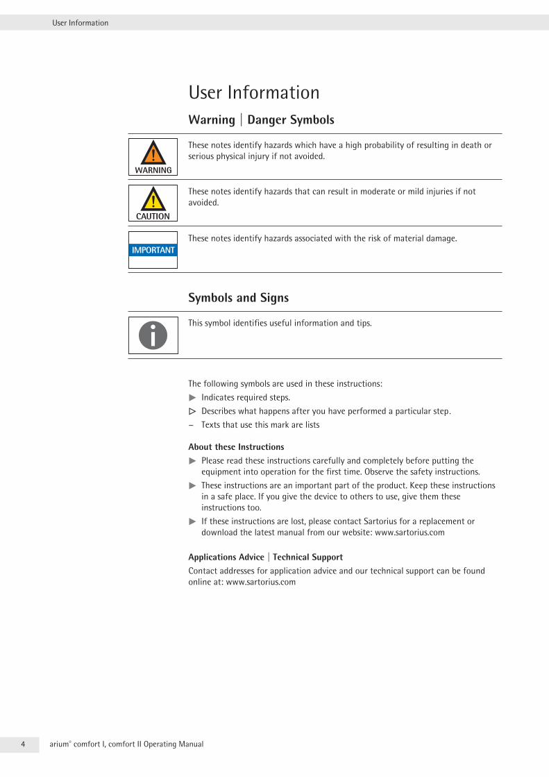
User InformationWarning | Danger Symbols
These notes identify hazards which have a high probability of resulting in death or serious physical injury if not avoided .
These notes identify hazards that can result in moderate or mild injuries if not avoided .
These notes identify hazards associated with the risk of material damage .
Symbols and Signs
This symbol identifies useful information and tips .
The following symbols are used in these instructions:
tt Indicates required steps .
y Describes what happens after you have performed a particular step. − Texts that use this mark are lists
About these Instructionstt Please read these instructions carefully and completely before putting the equipment into operation for the first time . Observe the safety instructions .
tt These instructions are an important part of the product . Keep these instructions in a safe place . If you give the device to others to use, give them these instructions too .
tt If these instructions are lost, please contact Sartorius for a replacement or download the latest manual from our website: www .sartorius .com
Applications Advice | Technical SupportContact addresses for application advice and our technical support can be found online at: www .sartorius .com
5arium® comfort I, comfort II Operating Manual
Safety Information
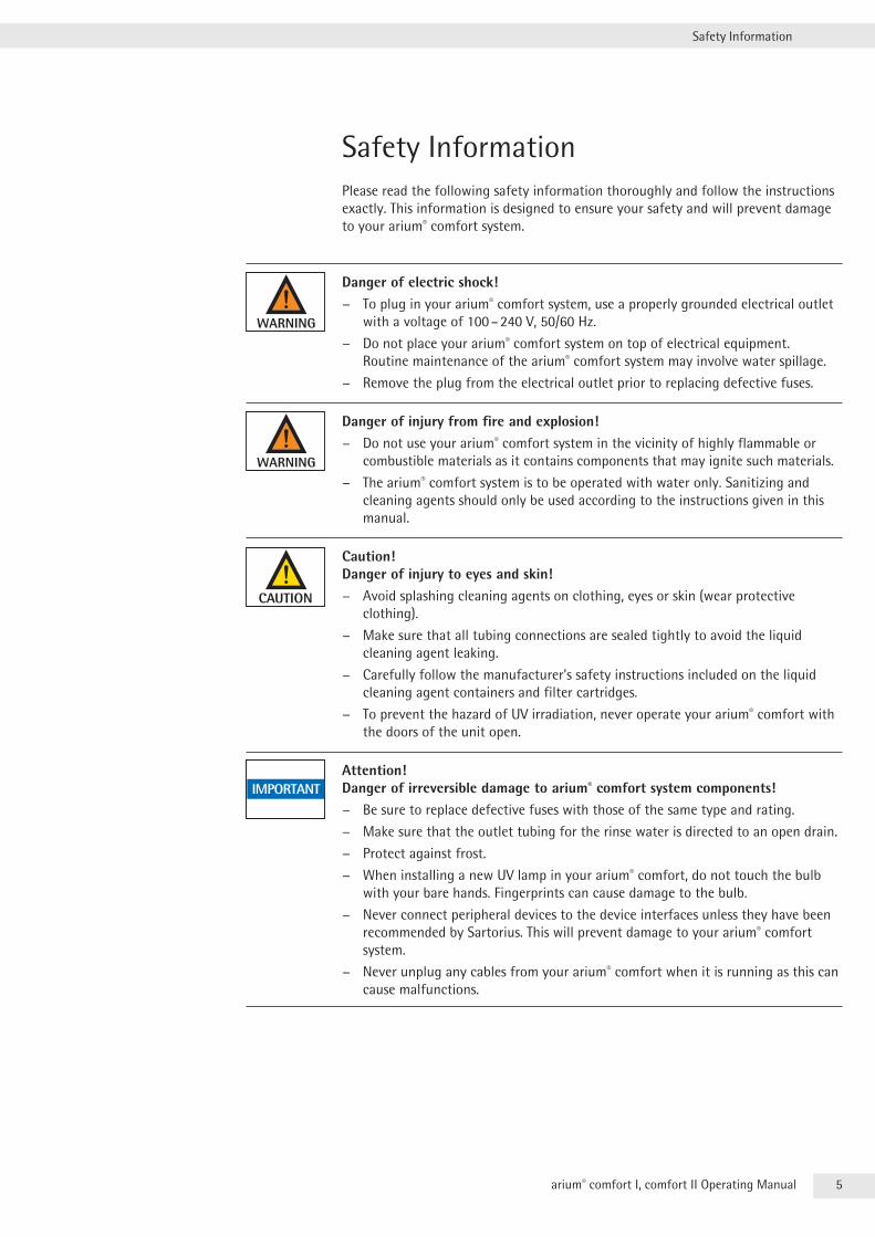
Safety InformationPlease read the following safety information thoroughly and follow the instructions exactly . This information is designed to ensure your safety and will prevent damage to your arium® comfort system .
Danger of electric shock! − To plug in your arium® comfort system, use a properly grounded electrical outlet
with a voltage of 100 – 240 V, 50/60 Hz .
− Do not place your arium® comfort system on top of electrical equipment . Routine maintenance of the arium® comfort system may involve water spillage .
− Remove the plug from the electrical outlet prior to replacing defective fuses .
Danger of injury from fire and explosion! − Do not use your arium® comfort system in the vicinity of highly flammable or
combustible materials as it contains components that may ignite such materials .
− The arium® comfort system is to be operated with water only . Sanitizing and cleaning agents should only be used according to the instructions given in this manual .
Caution! Danger of injury to eyes and skin!
− Avoid splashing cleaning agents on clothing, eyes or skin (wear protective clothing) .
− Make sure that all tubing connections are sealed tightly to avoid the liquid cleaning agent leaking .
− Carefully follow the manufacturer’s safety instructions included on the liquid cleaning agent containers and filter cartridges .
− To prevent the hazard of UV irradiation, never operate your arium® comfort with the doors of the unit open .
Attention! Danger of irreversible damage to arium® comfort system components!
− Be sure to replace defective fuses with those of the same type and rating .
− Make sure that the outlet tubing for the rinse water is directed to an open drain .
− Protect against frost .
− When installing a new UV lamp in your arium® comfort, do not touch the bulb with your bare hands . Fingerprints can cause damage to the bulb .
− Never connect peripheral devices to the device interfaces unless they have been recommended by Sartorius . This will prevent damage to your arium® comfort system .
− Never unplug any cables from your arium® comfort when it is running as this can cause malfunctions .
6 arium® comfort I, comfort II Operating Manual
Safety Information
Intended UseThe arium® comfort system was designed for the sole purpose of creating pure and ultrapure water for laboratory use . In order to ensure proper device operation, you should only use the filer media and | or accessories listed in this manual . Using the device for purposes other than that listed here is considered improper use .
− The arium® comfort system may only be operated by trained personnel .
− Only operate your arium® comfort system with original accessories or replacement parts . If you modify this water purification system independently, the performance and operating safety of the system are no longer guaranteed . This can also endanger the safety of the operator .
− If you encounter any problems with your system, please contact your local Sartorius Service Center .
− Please take all pertinent precautions to prevent accidents and observe the generally valid technical and occupational safety rules and regulations .
− Only use materials recommended by Sartorius (e .g . connections, seals, tools, spare parts, cleaning agents, pre-filter cartridges, softeners and RO modules) .
7arium® comfort I, comfort II Operating Manual
Product Description
1 Product Description
3
2
1
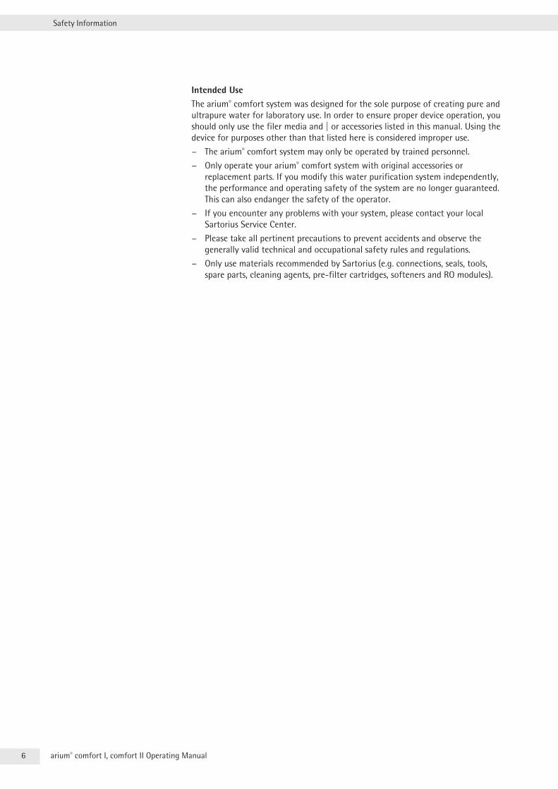
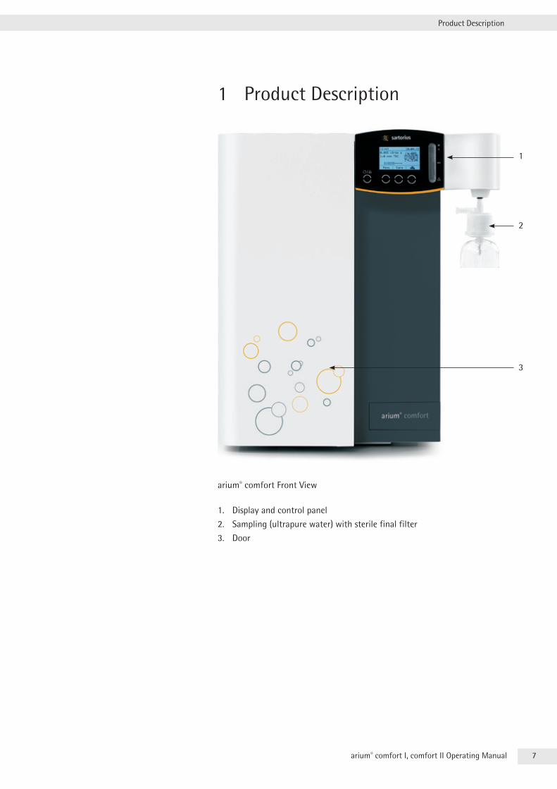
arium® comfort Front View
1 . Display and control panel
2 . Sampling (ultrapure water) with sterile final filter
3 . Door
8 arium® comfort I, comfort II Operating Manual
Product Description
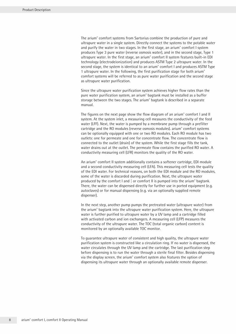
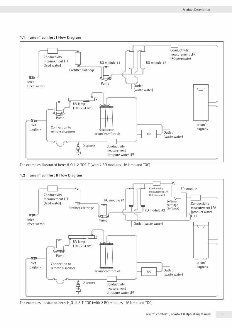
The arium® comfort systems from Sartorius combine the production of pure and ultrapure water in a single system . Directly connect the systems to the potable water and purify the water in two stages . In the first stage, an arium® comfort I system produces Type 3 pure water (reverse osmosis water), and in the second stage, Type 1 ultrapure water . In the first stage, an arium® comfort II system features built-in EDI technology (electrodeionization) and produces ASTM Type 2 ultrapure water . In the second stage, the system is identical to an arium® comfort I and produces ASTM Type 1 ultrapure water . In the following, the first purification stage for both arium® comfort systems will be referred to as pure water purification and the second stage as ultrapure water purification .
Since the ultrapure water purification system achieves higher flow rates than the pure water purification system, an arium® bagtank must be installed as a buffer storage between the two stages . The arium® bagtank is described in a separate manual .
The figures on the next page show the flow diagram of an arium® comfort I and II system . At the system inlet, a measuring cell measures the conductivity of the feed water (LFF) . Next, the water is pumped by a membrane pump through a prefilter cartridge and the RO modules (reverse osmosis modules) . arium® comfort systems can be optionally equipped with one or two RO modules . Each RO module has two outlets: one for permeate and one for concentrate flow . The concentrate flow is connected to the outlet (drain) of the system . While the first stage fills the tank, water drains out at the outlet . The permeate flow contains the purified RO water . A conductivity measuring cell (LFR) monitors the quality of the RO water .
An arium® comfort II system additionally contains a softener cartridge, EDI module and a second conductivity measuring cell (LFA) . This measuring cell tests the quality of the EDI water . For technical reasons, on both the EDI module and the RO modules, some of the water is discarded during purification . Next, the ultrapure water produced by the comfort I and | or comfort II is pumped into the arium® bagtank . There, the water can be dispensed directly for further use in ported equipment (e .g . autoclaves) or for manual dispensing (e .g . via an optionally supplied remote dispenser) .
In the next step, another pump pumps the pretreated water (ultrapure water) from the arium® bagtank into the ultrapure water purification system . Here, the ultrapure water is further purified to ultrapure water by a UV lamp and a cartridge filled with activated carbon and ion exchangers . A measuring cell (LFP) measures the conductivity of the ultrapure water . The TOC (total organic carbon) content is monitored by an optionally available TOC monitor .
To guarantee ultrapure water of consistent and high quality, the ultrapure water purification system is constructed like a circulation ring . If no water is dispensed, the water circulates through the UV lamp and the cartridge . The last purification step before dispensing is to run the water through a sterile final filter . Besides dispensing via the display screen, the arium® comfort system also features the option of dispensing its ultrapure water through an optionally available remote dispenser .
9arium® comfort I, comfort II Operating Manual
Product Description
1.1 arium® comfort I Flow Diagram
The examples illustrated here: H2O-I-2-TOC-T (with 2 RO modules, UV lamp and TOC)
1.2 arium® comfort II Flow Diagram
The examples illustrated here: H2O-II-2-T-TOC (with 2 RO modules, UV lamp and TOC)
Conductivity measurement LFF (feed water)
Inlet (feed water)
Prefilter cartridge
RO module #1
Pump
arium® bagtank
Outlet (waste water)
Conductivity measurement LFR (RO permeate)
RO module #2
Inlet bagtank
Pump
UV lamp (185|254 nm)
arium® comfort kit
Conductivity measurement ultrapure water LFP
Outlet (waste water)
Conductivity measurement LFF (feed water)
Inlet (feed water)
RO module #1
Pump
arium® bagtank
Outlet (waste water)
RO module #2
Inlet bagtank
Pump
UV lamp (185|254 nm)
arium® comfort kit
Conductivity measurement ultrapure water LFP
Outlet (waste water)
Conductivity measurement LFA (product water EDI)
Softener cartridge (Softener)
Conductivity measurement LFR (RO permeate)
EDI module
Prefilter cartridge
Connection to remote dispenser
Dispense
Connection to remote dispenser
Dispense
10 arium® comfort I, comfort II Operating Manual
Product Description
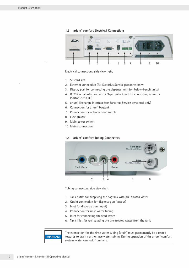
1.3 arium® comfort Electrical Connections
21 53 4 6 7 8 9 10
Electrical connections, side view right
1 . SD card slot
2 . Ethernet connection (for Sartorius Service personnel only)
3 . Display port for connecting the dispenser unit (on below-bench units)
4 . RS232 serial interface with a 9-pin sub-D port for connecting a printer (Sartorius YDP30)
5 . arium® Exchange interface (for Sartorius Service personnel only)
6 . Connection for arium® bagtank
7 . Connection for optional foot switch
8 . Fuse drawer
9 . Main power switch
10 . Mains connection
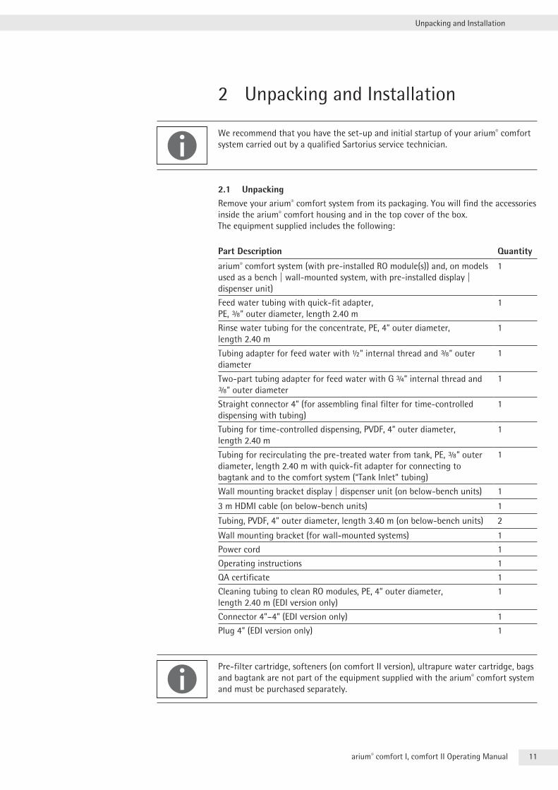
1.4 arium® comfort Tubing Connectors
Tubing connectors, side view right
1 . Tank outlet for supplying the bagtank with pre-treated water
2 . Outlet connection for dispense gun (output)
3 . Inlet for dispense gun (input)
4 . Connection for rinse water tubing
5 . Inlet for connecting the feed water
6 . Tank inlet for recirculating the pre-treated water from the tank
The connection for the rinse water tubing (drain) must permanently be directed towards to drain via the rinse water tubing . During operation of the arium® comfort system, water can leak from here .
1 43 62 5
11arium® comfort I, comfort II Operating Manual
Unpacking and Installation
2 Unpacking and Installation
We recommend that you have the set-up and initial startup of your arium® comfort system carried out by a qualified Sartorius service technician .
2.1 UnpackingRemove your arium® comfort system from its packaging . You will find the accessories inside the arium® comfort housing and in the top cover of the box . The equipment supplied includes the following:
Part Description Quantity
arium® comfort system (with pre-installed RO module(s)) and, on models used as a bench | wall-mounted system, with pre-installed display | dispenser unit)
1
Feed water tubing with quick-fit adapter,PE, a” outer diameter, length 2 .40 m
1
Rinse water tubing for the concentrate, PE, 4” outer diameter,length 2 .40 m
1
Tubing adapter for feed water with 1” internal thread and a” outer diameter
1
Two-part tubing adapter for feed water with G 3” internal thread and a” outer diameter
1
Straight connector 4” (for assembling final filter for time-controlled dispensing with tubing)
1
Tubing for time-controlled dispensing, PVDF, 4” outer diameter, length 2 .40 m
1
Tubing for recirculating the pre-treated water from tank, PE, a” outer diameter, length 2 .40 m with quick-fit adapter for connecting to bagtank and to the comfort system (“Tank Inlet” tubing)
1
Wall mounting bracket display | dispenser unit (on below-bench units) 1
3 m HDMI cable (on below-bench units) 1
Tubing, PVDF, 4” outer diameter, length 3 .40 m (on below-bench units) 2
Wall mounting bracket (for wall-mounted systems) 1
Power cord 1
Operating instructions 1
QA certificate 1
Cleaning tubing to clean RO modules, PE, 4” outer diameter, length 2 .40 m (EDI version only)
1
Connector 4”–4” (EDI version only) 1
Plug 4” (EDI version only) 1
Pre-filter cartridge, softeners (on comfort II version), ultrapure water cartridge, bags and bagtank are not part of the equipment supplied with the arium® comfort system and must be purchased separately .
12 arium® comfort I, comfort II Operating Manual
Unpacking and Installation
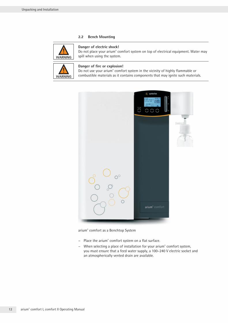
2.2 Bench Mounting
Danger of electric shock! Do not place your arium® comfort system on top of electrical equipment . Water may spill when using the system .
Danger of fire or explosion! Do not use your arium® comfort system in the vicinity of highly flammable or combustible materials as it contains components that may ignite such materials .
arium® comfort as a Benchtop System
− Place the arium® comfort system on a flat surface .
− When selecting a place of installation for your arium® comfort system, you must ensure that a feed water supply, a 100–240 V electric socket and an atmospherically vented drain are available .
13arium® comfort I, comfort II Operating Manual
Unpacking and Installation
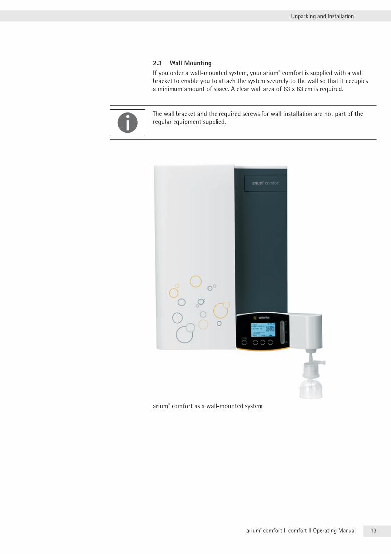
2.3 Wall MountingIf you order a wall-mounted system, your arium® comfort is supplied with a wall bracket to enable you to attach the system securely to the wall so that it occupies a minimum amount of space . A clear wall area of 63 x 63 cm is required .
The wall bracket and the required screws for wall installation are not part of the regular equipment supplied .
arium® comfort as a wall-mounted system
14 arium® comfort I, comfort II Operating Manual
Unpacking and Installation
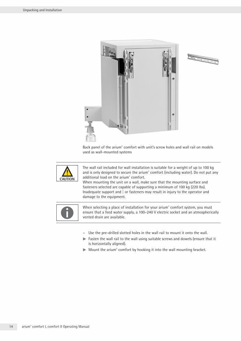
Back panel of the arium® comfort with unit’s screw holes and wall rail on models used as wall-mounted systems
The wall rail included for wall installation is suitable for a weight of up to 100 kg and is only designed to secure the arium® comfort (including water) . Do not put any additional load on the arium® comfort . When mounting the unit on a wall, make sure that the mounting surface and fasteners selected are capable of supporting a minimum of 100 kg (220 lbs) . Inadequate support and | or fasteners may result in injury to the operator and damage to the equipment .
When selecting a place of installation for your arium® comfort system, you must ensure that a feed water supply, a 100–240 V electric socket and an atmospherically vented drain are available .
− Use the pre-drilled slotted holes in the wall rail to mount it onto the wall .
tt Fasten the wall rail to the wall using suitable screws and dowels (ensure that it is horizontally aligned) .
tt Mount the arium® comfort by hooking it into the wall mounting bracket .
15arium® comfort I, comfort II Operating Manual
Unpacking and Installation
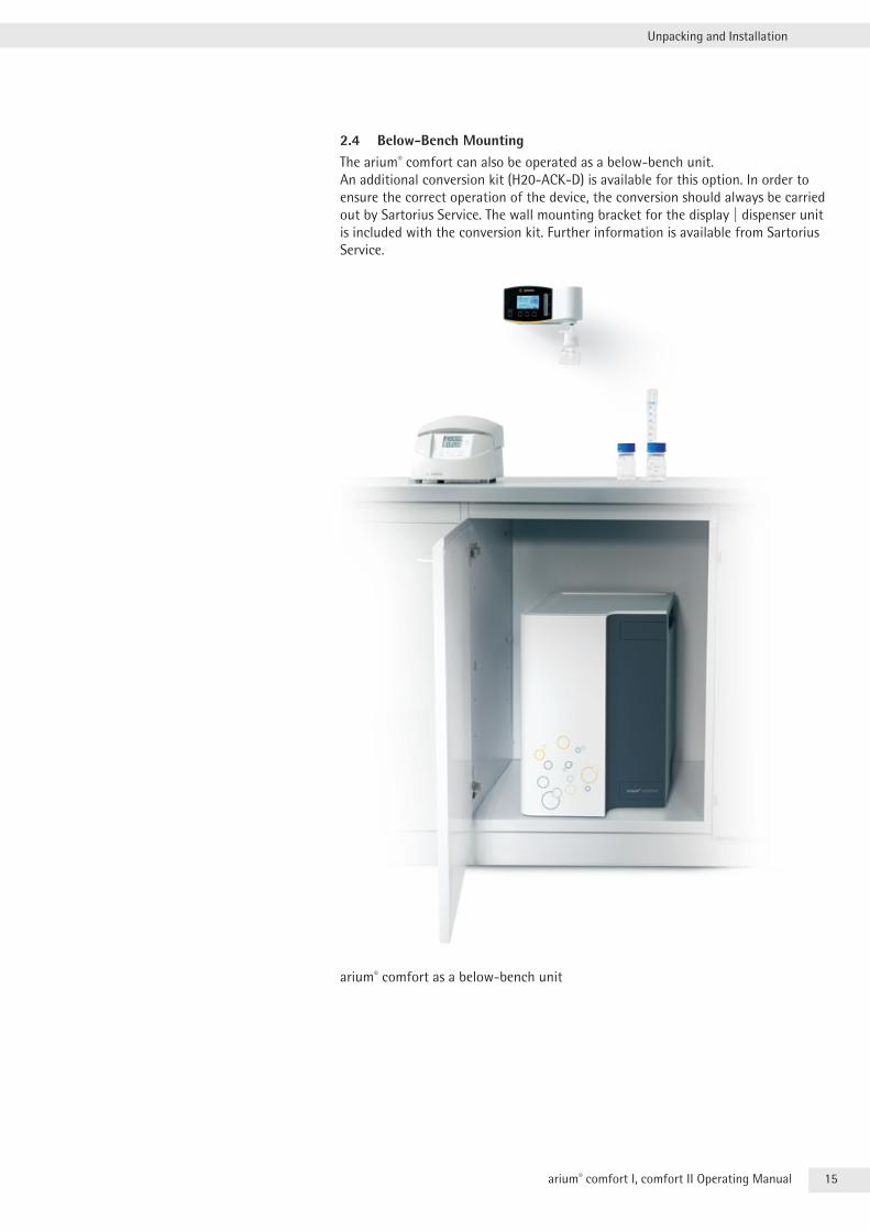
2.4 Below-Bench MountingThe arium® comfort can also be operated as a below-bench unit . An additional conversion kit (H20-ACK-D) is available for this option . In order to ensure the correct operation of the device, the conversion should always be carried out by Sartorius Service . The wall mounting bracket for the display | dispenser unit is included with the conversion kit . Further information is available from Sartorius Service .
arium® comfort as a below-bench unit
16 arium® comfort I, comfort II Operating Manual
Unpacking and Installation
2.5 arium® bagtank
An arium® comfort system can only be operated in combination with an arium® bagtank!
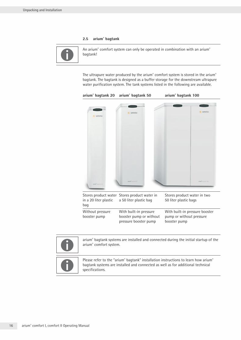
The ultrapure water produced by the arium® comfort system is stored in the arium® bagtank . The bagtank is designed as a buffer storage for the downstream ultrapure water purification system . The tank systems listed in the following are available .
arium® bagtank 20 arium® bagtank 50 arium® bagtank 100
Stores product water in a 20 liter plastic bag
Stores product water in a 50 liter plastic bag
Stores product water in two 50 liter plastic bags
Without pressure booster pump
With built-in pressure booster pump or without pressure booster pump
With built-in pressure booster pump or without pressure booster pump
arium® bagtank systems are installed and connected during the initial startup of the arium® comfort system .
Please refer to the “arium® bagtank” installation instructions to learn how arium® bagtank systems are installed and connected as well as for additional technical specifications .
17arium® comfort I, comfort II Operating Manual
Operating Concept
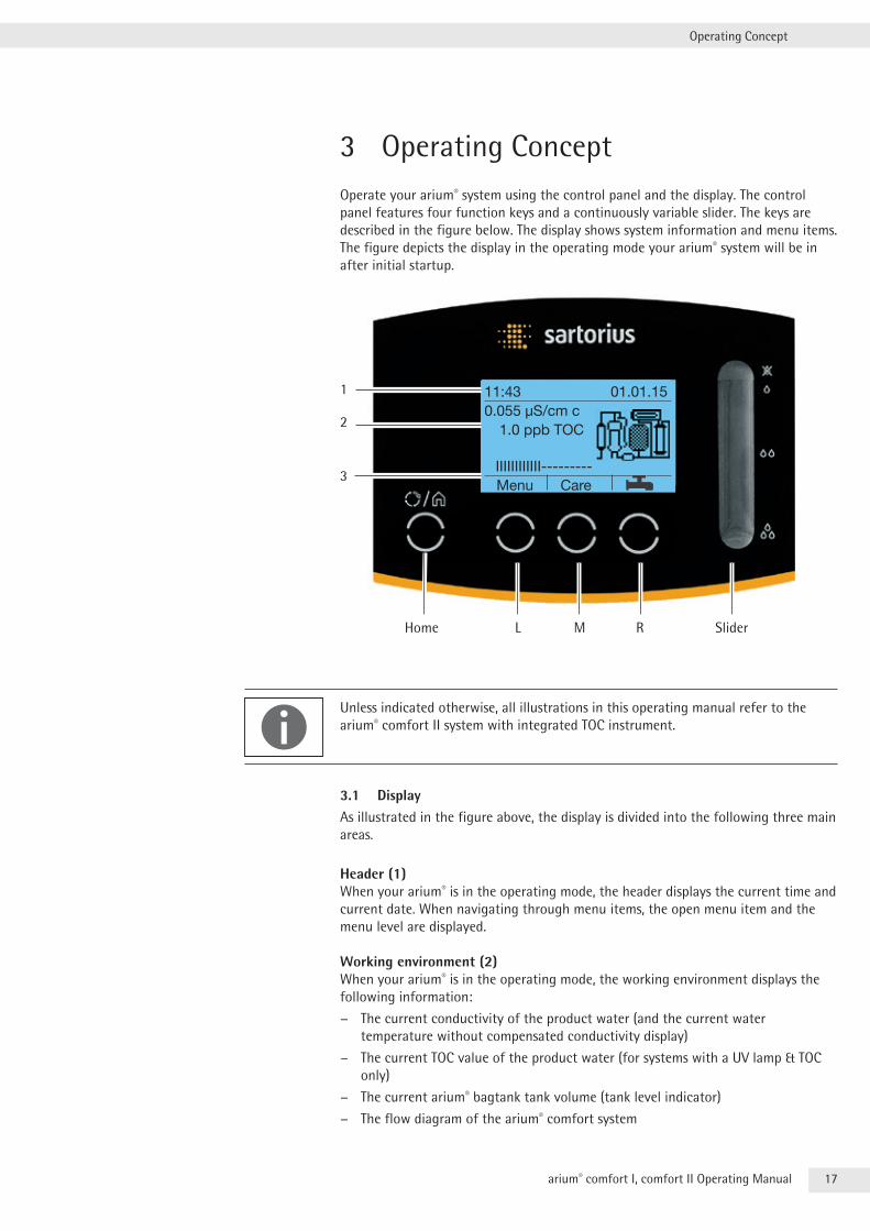
3 Operating ConceptOperate your arium® system using the control panel and the display . The control panel features four function keys and a continuously variable slider . The keys are described in the figure below . The display shows system information and menu items . The figure depicts the display in the operating mode your arium® system will be in after initial startup .
11:43 01.01.150.055 µS/cm c 1.0 ppb TOC
IIIIIIIIIIII--------- Menu Care
1
2
3
Home RML Slider
Unless indicated otherwise, all illustrations in this operating manual refer to the arium® comfort II system with integrated TOC instrument .
3.1 DisplayAs illustrated in the figure above, the display is divided into the following three main areas .
Header (1)When your arium® is in the operating mode, the header displays the current time and current date . When navigating through menu items, the open menu item and the menu level are displayed .
Working environment (2)When your arium® is in the operating mode, the working environment displays the following information:
− The current conductivity of the product water (and the current water temperature without compensated conductivity display)
− The current TOC value of the product water (for systems with a UV lamp & TOC only)
− The current arium® bagtank tank volume (tank level indicator)
− The flow diagram of the arium® comfort system
18 arium® comfort I, comfort II Operating Manual
Operating Concept
The flow chart shows the system purification components (pre-treatment cartridge, RO modules, softener (on comfort II version only), the storage tank, arium® bagtank, the UV lamp (system with a UV lamp only) and the ultrapure water cartridge . As soon as a component change is due, the corresponding element starts blinking and a warning message appears .
If your arium® comfort system is not in the operating mode, the working environment of the display shows the current menu item .
Footer (3)The footer displays the current key function assignment for the keys L, M and R .
3.2 Operation in the Operating ModeThe keys L, M, R and ECO/Home and the slider are available for operation in the operating mode .
“Menu” Key (L)You can use this key to switch to the system menu . Information on the system menu can be found in Chapter “6 . Menu” .
“Care” Key (M)You can use this key to switch to the care section . Information on the care menu can be found in Chapter “7 . Care” .
“Dispense” Key (R)You can use this key to switch directly to controlled water dispensing . Here you have the option to select between timed dispense or volume-controlled dispensing . Further information can be found in Chapter “5 .2 Dispensing Ultrapure Water” .
SliderUse the slider to start manual product water dispensing . Further information can be found in Chapter “5 .2 Dispensing Ultrapure Water” .
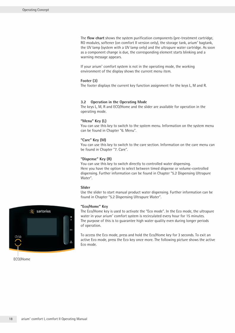
“Eco/Home” KeyThe Eco/Home key is used to activate the “Eco mode” . In the Eco mode, the ultrapure water in your arium® comfort system is recirculated every hour for 15 minutes . The purpose of this is to guarantee high water quality even during longer periods of operation .
To access the Eco mode, press and hold the Eco/Home key for 3 seconds . To exit an active Eco mode, press the Eco key once more . The following picture shows the active Eco mode .
ECO/Home
19arium® comfort I, comfort II Operating Manual
Operating Concept
Your arium® comfort system also features an automatic ECO mode . This automatic ECO mode is activated by default and returns the system to the Eco mode after the Eco time has elapsed . The Eco time starts after the last entry into the system . It can be configured in the System menu (see Chapter “6 .3 .4 ECO Mode”, page 46) .
Key Locking FunctionThe arium® comfort system has a key locking function . When the key locking function is active, it is not possible to dispense water, not even with a foot switch . All other functions (measurement, expiry of ECO time, print interval, memory interval, and error and warning messages) continue to run in the background . When the automatic ECO time has elapsed, the device enters ECO mode and automatically removes the key lock so that the device is once again ready for operation upon leaving ECO mode . If a warning or an error appears while the key lock is activated, the device will likewise automatically cancel the key lock and display the corresponding message .
To activate the key lock, simultaneously press the Eco/Home key and the “Dispense” Key (R) . Use the same key combination to deactivate the key locking function .
20 arium® comfort I, comfort II Operating Manual
Operating Concept
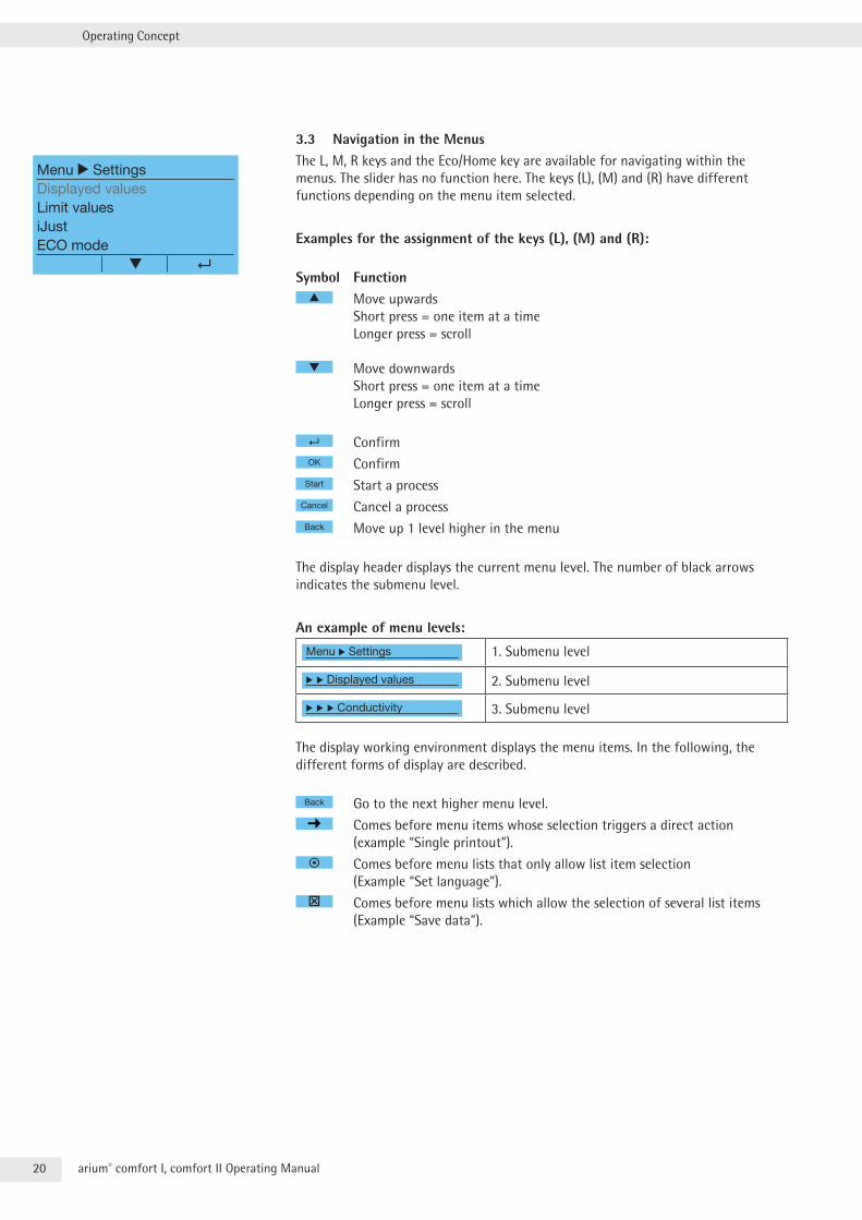
3.3 Navigation in the MenusThe L, M, R keys and the Eco/Home key are available for navigating within the menus . The slider has no function here . The keys (L), (M) and (R) have different functions depending on the menu item selected .
Examples for the assignment of the keys (L), (M) and (R):
Symbol Function▲ Move upwards
Short press = one item at a time Longer press = scroll
Move downwards Short press = one item at a time Longer press = scroll
ConfirmOK Confirm
Start Start a processCancel Cancel a processBack Move up 1 level higher in the menu
The display header displays the current menu level . The number of black arrows indicates the submenu level .
An example of menu levels:
Menu r Settings 1 . Submenu level
r r Displayed values 2 . Submenu level
r r r Conductivity 3 . Submenu level
The display working environment displays the menu items . In the following, the different forms of display are described .
Back Go to the next higher menu level .
Comes before menu items whose selection triggers a direct action (example “Single printout”) .
Comes before menu lists that only allow list item selection (Example “Set language”) .
Comes before menu lists which allow the selection of several list items (Example “Save data”) .
Menu r SettingsDisplayed valuesLimit valuesiJustECO mode
21arium® comfort I, comfort II Operating Manual
Operating Concept
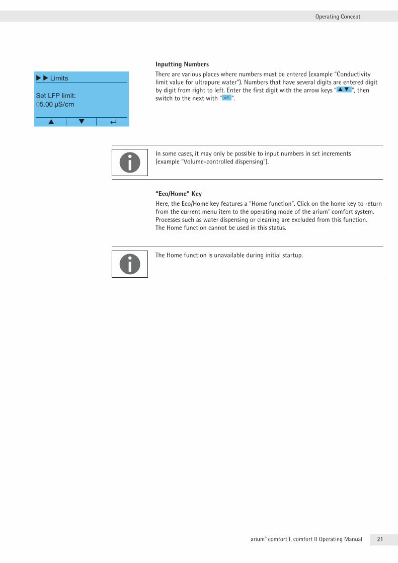
Inputting NumbersThere are various places where numbers must be entered (example “Conductivity limit value for ultrapure water”) . Numbers that have several digits are entered digit by digit from right to left . Enter the first digit with the arrow keys “ ▲ ▼ ”, then switch to the next with “ ” .
In some cases, it may only be possible to input numbers in set increments (example “Volume-controlled dispensing”) .
“Eco/Home” KeyHere, the Eco/Home key features a “Home function” . Click on the home key to return from the current menu item to the operating mode of the arium® comfort system . Processes such as water dispensing or cleaning are excluded from this function . The Home function cannot be used in this status .
The Home function is unavailable during initial startup .
r r Limits
Set LFP limit:05.00 µS/cm
▲
22 arium® comfort I, comfort II Operating Manual
Initial Startup
4 Initial StartupOnce the arium® comfort and arium® bagtank have been set up and connected, you can put your system into operation .
According to device specifications (arium® comfort and arium® bagtank), this requires a supply voltage of 230 - 240 V, 50 Hz or 115 V, 60 Hz, depending on the country standard . You may not connect the system to the power supply if the connection conditions at the setup location do not correspond to the information on the manufacturer’s ID labels for the arium® comfort and arium® bagtank .
It takes between 210 and 330 minutes to set up the arium® comfort (depending on the version of the device) .
For initial startup, carry out steps 4 .1 to 4 .12 . This operating manual will guide you step-by-step through the sequence of the displays .
4.1 System Startup
All system settings (e .g . date, time, displayed values, etc .) configured during initial startup can be subsequently changed in the system menu .
tt Connect the power plug on the power supply of your arium® comfort systems to the mains voltage . Next, switch on your arium® comfort system via the power switch .
The arium® comfort system will then perform a system check and display the start screen shown on the right .
23arium® comfort I, comfort II Operating Manual
Initial Startup
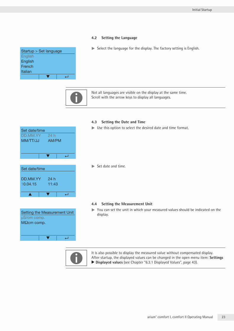
4.2 Setting the Language
tt Select the language for the display . The factory setting is English .
Not all languages are visible on the display at the same time . Scroll with the arrow keys to display all languages .
4.3 Setting the Date and Timett Use this option to select the desired date and time format .
tt Set date and time .
4.4 Setting the Measurement Unittt You can set the unit in which your measured values should be indicated on the display .
It is also possible to display the measured value without compensated display . After startup, the displayed values can be changed in the open menu item: Settings r Displayed values (see Chapter “6 .3 .1 Displayed Values”, page 43) .
Startup > Set languageEnglishEnglishFrenchItalian
Set date/timeDD.MM.YY 24 hMM/TT/JJ AM/PM
Set date/time
DD.MM.YY 24 h10.04.15 11:43
▲
Setting the Measurement UnitµS/cm comp.MΩcm comp.
24 arium® comfort I, comfort II Operating Manual
Initial Startup
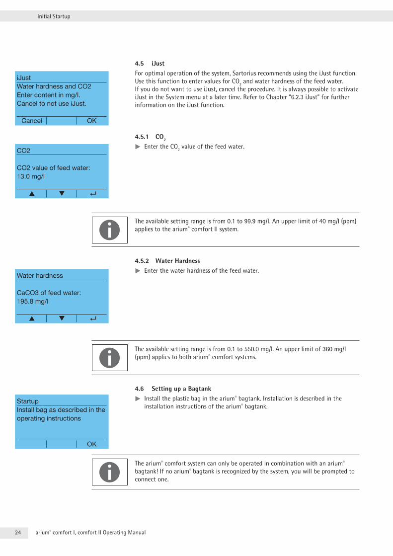
4.5 iJustFor optimal operation of the system, Sartorius recommends using the iJust function . Use this function to enter values for CO2 and water hardness of the feed water . If you do not want to use iJust, cancel the procedure . It is always possible to activate iJust in the System menu at a later time . Refer to Chapter “6 .2 .3 iJust” for further information on the iJust function .
4.5.1 CO2
tt Enter the CO2 value of the feed water .
The available setting range is from 0 .1 to 99 .9 mg/l . An upper limit of 40 mg/l (ppm) applies to the arium® comfort II system .
4.5.2 Water Hardnesstt Enter the water hardness of the feed water .
The available setting range is from 0 .1 to 550 .0 mg/l . An upper limit of 360 mg/l (ppm) applies to both arium® comfort systems .
4.6 Setting up a Bagtanktt Install the plastic bag in the arium® bagtank . Installation is described in the installation instructions of the arium® bagtank .
The arium® comfort system can only be operated in combination with an arium® bagtank! If no arium® bagtank is recognized by the system, you will be prompted to connect one .
iJustWater hardness and CO2Enter content in mg/l.Cancel to not use iJust.
Cancel OK
CO2
CO2 value of feed water:13.0 mg/l
▲
Water hardness
CaCO3 of feed water:195.8 mg/l
▲
StartupInstall bag as described in the operating instructions
OK
25arium® comfort I, comfort II Operating Manual
Initial Startup
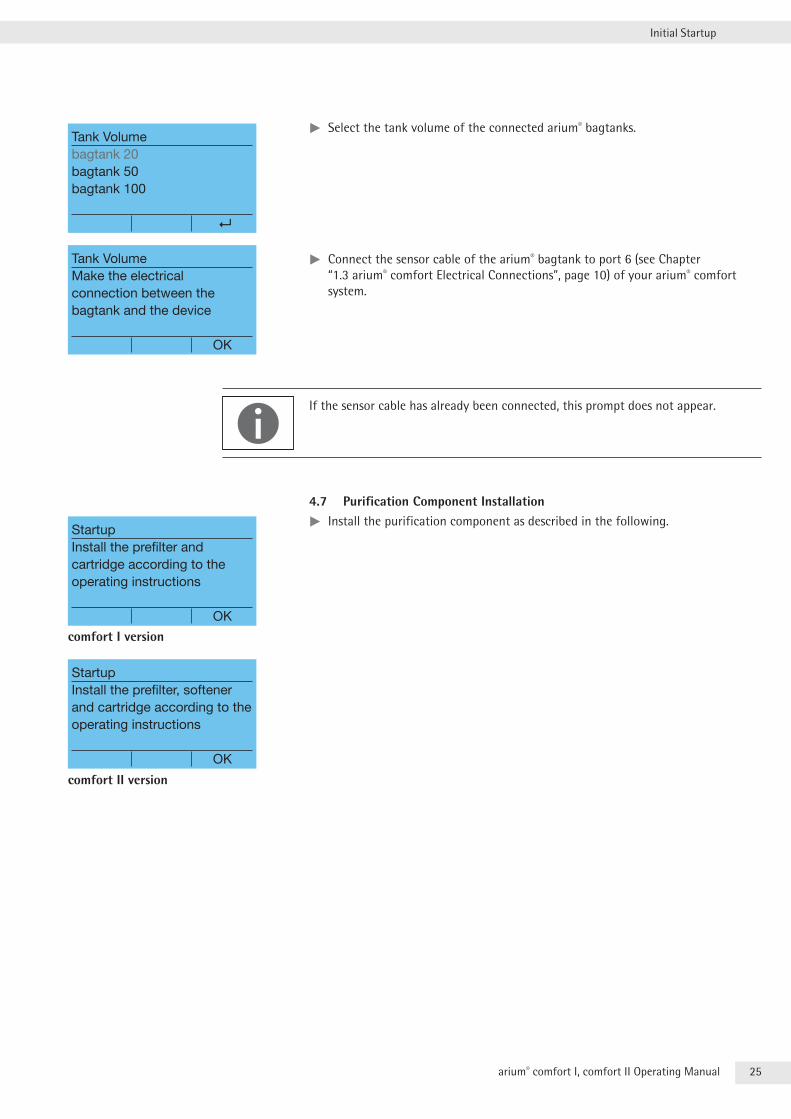
tt Select the tank volume of the connected arium® bagtanks .
tt Connect the sensor cable of the arium® bagtank to port 6 (see Chapter “1 .3 arium® comfort Electrical Connections”, page 10) of your arium® comfort system .
If the sensor cable has already been connected, this prompt does not appear .
4.7 Purification Component Installationtt Install the purification component as described in the following .
Tank Volumebagtank 20bagtank 50bagtank 100
Tank VolumeMake the electrical connection between the bagtank and the device
OK
StartupInstall the prefilter and cartridge according to the operating instructions
OK
comfort I version
StartupInstall the prefilter, softener and cartridge according to the operating instructions
OK
comfort II version
26 arium® comfort I, comfort II Operating Manual
Initial Startup
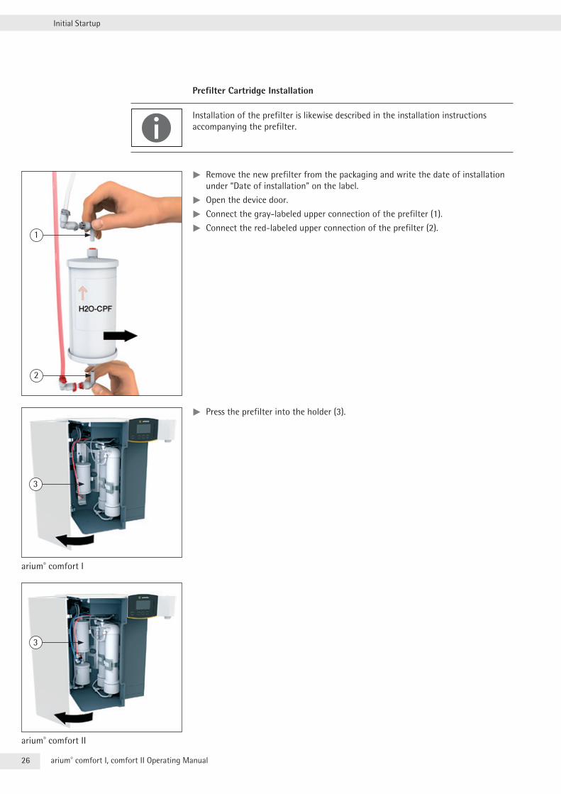
Prefilter Cartridge Installation
Installation of the prefilter is likewise described in the installation instructions accompanying the prefilter .
tt Remove the new prefilter from the packaging and write the date of installation under “Date of installation” on the label .
tt Open the device door .
tt Connect the gray-labeled upper connection of the prefilter (1) .
tt Connect the red-labeled upper connection of the prefilter (2) .
tt Press the prefilter into the holder (3) .
1
2
3
arium® comfort I
3
arium® comfort II
27arium® comfort I, comfort II Operating Manual
Initial Startup
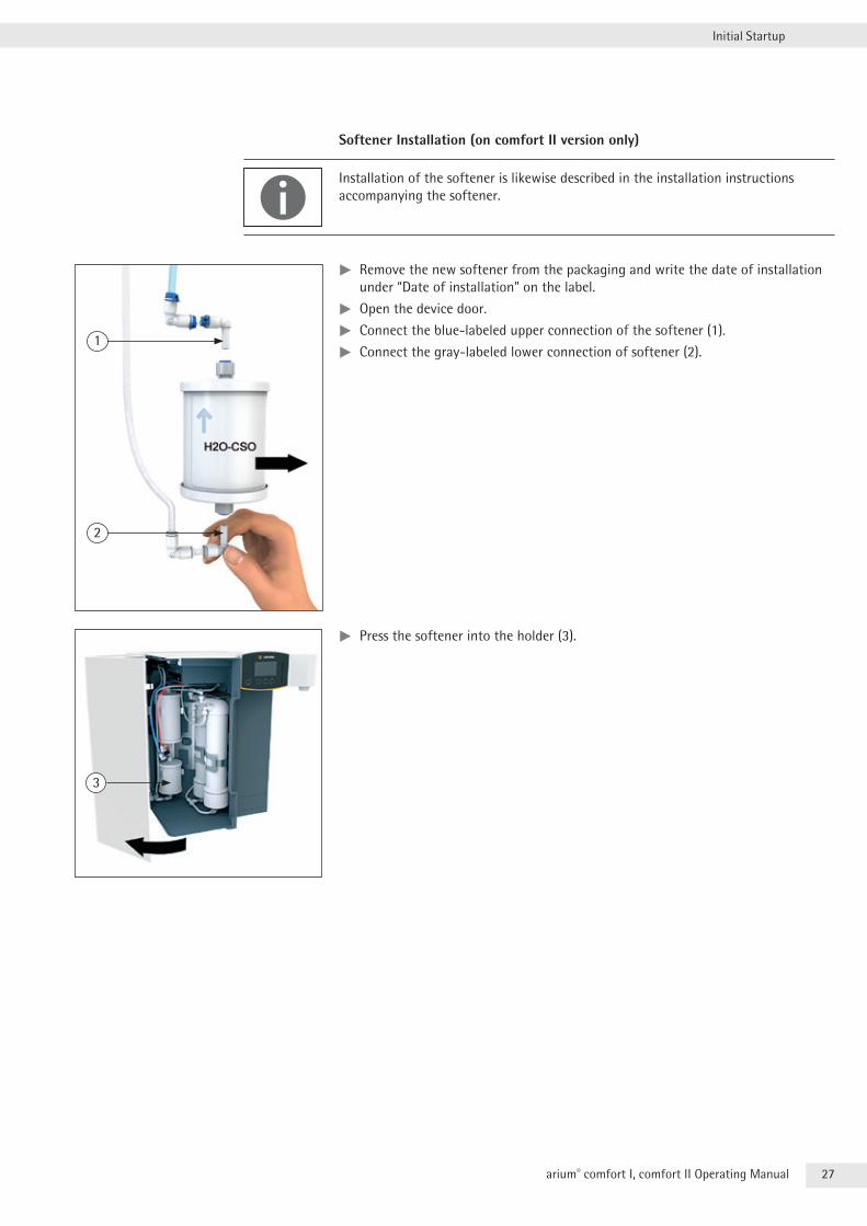
Softener Installation (on comfort II version only)
Installation of the softener is likewise described in the installation instructions accompanying the softener .
tt Remove the new softener from the packaging and write the date of installation under “Date of installation” on the label .
tt Open the device door .
tt Connect the blue-labeled upper connection of the softener (1) .
tt Connect the gray-labeled lower connection of softener (2) .
tt Press the softener into the holder (3) .
1
2
3
28 arium® comfort I, comfort II Operating Manual
Initial Startup
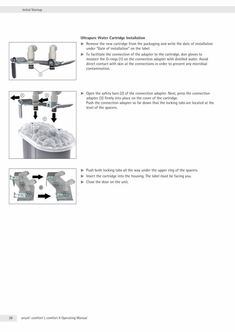
Ultrapure Water Cartridge Installationtt Remove the new cartridge from the packaging and write the date of installation under “Date of installation” on the label .
tt To facilitate the connection of the adapter to the cartridge, don gloves to moisten the O-rings (1) on the connection adapter with distilled water . Avoid direct contact with skin at the connections in order to prevent any microbial contamination .
tt Open the safety bars (2) of the connection adapter . Next, press the connection adapter (3) firmly into place on the cover of the cartridge . Push the connection adapter so far down that the locking tabs are located at the level of the spacers .
tt Push both locking tabs all the way under the upper ring of the spacers .
tt Insert the cartridge into the housing . The label must be facing you .
tt Close the door on the unit .
29arium® comfort I, comfort II Operating Manual
Initial Startup
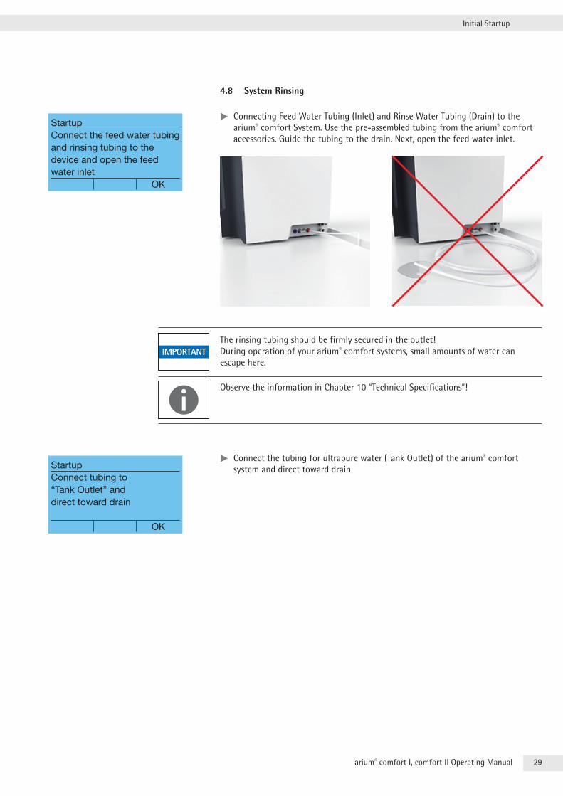
4.8 System Rinsing
tt Connecting Feed Water Tubing (Inlet) and Rinse Water Tubing (Drain) to the arium® comfort System . Use the pre-assembled tubing from the arium® comfort accessories . Guide the tubing to the drain . Next, open the feed water inlet .
The rinsing tubing should be firmly secured in the outlet! During operation of your arium® comfort systems, small amounts of water can escape here .
Observe the information in Chapter 10 “Technical Specifications”!
tt Connect the tubing for ultrapure water (Tank Outlet) of the arium® comfort system and direct toward drain .
StartupConnect the feed water tubing and rinsing tubing to the device and open the feed water inlet OK
StartupConnect tubing to “Tank Outlet” and direct toward drain
OK
30 arium® comfort I, comfort II Operating Manual
Initial Startup
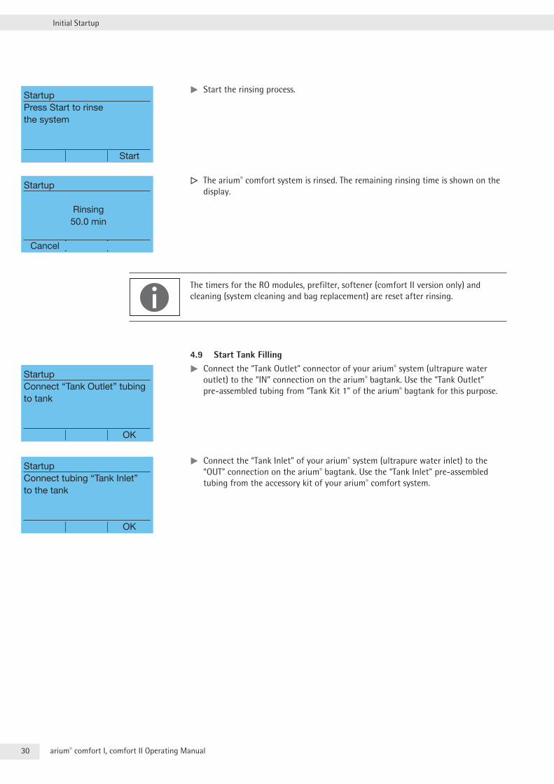
tt Start the rinsing process .
y The arium® comfort system is rinsed . The remaining rinsing time is shown on the display .
The timers for the RO modules, prefilter, softener (comfort II version only) and cleaning (system cleaning and bag replacement) are reset after rinsing .
4.9 Start Tank Fillingtt Connect the “Tank Outlet” connector of your arium® system (ultrapure water outlet) to the “IN” connection on the arium® bagtank . Use the “Tank Outlet” pre-assembled tubing from “Tank Kit 1” of the arium® bagtank for this purpose .
tt Connect the “Tank Inlet” of your arium® system (ultrapure water inlet) to the “OUT” connection on the arium® bagtank . Use the “Tank Inlet” pre-assembled tubing from the accessory kit of your arium® comfort system .
StartupPress Start to rinse the system
Start
Startup
Rinsing 50.0 min
Cancel
StartupConnect “Tank Outlet” tubing to tank
OK
StartupConnect tubing “Tank Inlet” to the tank
OK
31arium® comfort I, comfort II Operating Manual
Initial Startup
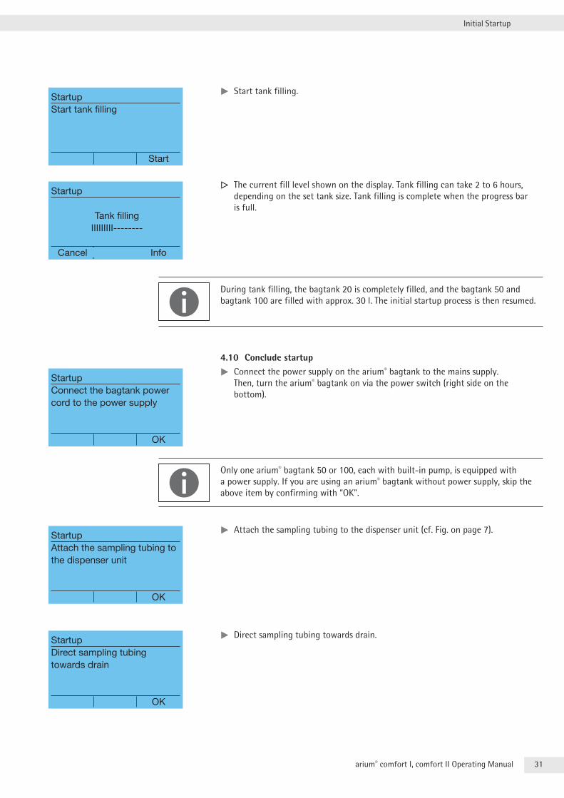
tt Start tank filling .
y The current fill level shown on the display . Tank filling can take 2 to 6 hours, depending on the set tank size . Tank filling is complete when the progress bar is full .
During tank filling, the bagtank 20 is completely filled, and the bagtank 50 and bagtank 100 are filled with approx . 30 l . The initial startup process is then resumed .
4.10 Conclude startuptt Connect the power supply on the arium® bagtank to the mains supply . Then, turn the arium® bagtank on via the power switch (right side on the bottom) .
Only one arium® bagtank 50 or 100, each with built-in pump, is equipped with a power supply . If you are using an arium® bagtank without power supply, skip the above item by confirming with “OK” .
tt Attach the sampling tubing to the dispenser unit (cf . Fig . on page 7) .
tt Direct sampling tubing towards drain .
StartupStart tank filling
Start
Startup
Tank filling IIIIIIIII--------
Cancel Info
StartupConnect the bagtank power cord to the power supply
OK
StartupAttach the sampling tubing to the dispenser unit
OK
StartupDirect sampling tubingtowards drain
OK
32 arium® comfort I, comfort II Operating Manual
Initial Startup
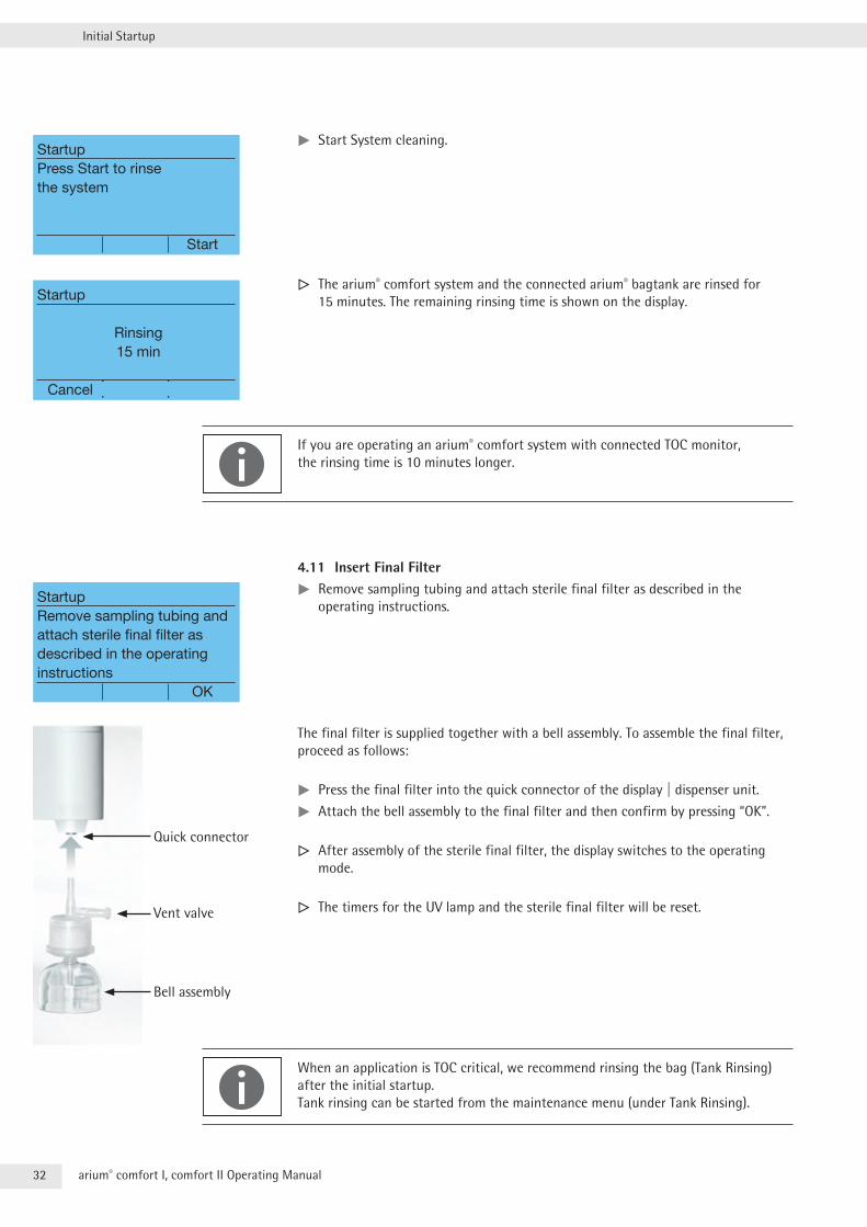
tt Start System cleaning .
y The arium® comfort system and the connected arium® bagtank are rinsed for 15 minutes . The remaining rinsing time is shown on the display .
If you are operating an arium® comfort system with connected TOC monitor, the rinsing time is 10 minutes longer .
4.11 Insert Final Filtertt Remove sampling tubing and attach sterile final filter as described in the operating instructions .
The final filter is supplied together with a bell assembly . To assemble the final filter, proceed as follows:
tt Press the final filter into the quick connector of the display | dispenser unit .
tt Attach the bell assembly to the final filter and then confirm by pressing “OK” .
y After assembly of the sterile final filter, the display switches to the operating mode .
y The timers for the UV lamp and the sterile final filter will be reset .
When an application is TOC critical, we recommend rinsing the bag (Tank Rinsing) after the initial startup . Tank rinsing can be started from the maintenance menu (under Tank Rinsing) .
StartupPress Start to rinse the system
Start
Startup
Rinsing 15 min
Cancel
StartupRemove sampling tubing and attach sterile final filter as described in the operating instructions OK
Quick connector
Vent valve
Bell assembly
33arium® comfort I, comfort II Operating Manual
Initial Startup
4.12 Rinsing the Final Filtertt Place a collection vessel (min . 6 liter capacity) with calibration marks under the final filter . Then, open the water dispensing and rinse the final filter with 6 liters of water . During rinsing, open the vent valve of the final filter so that enclosed air can escape .
tt Afterwards, attach the protective cap to the bell assembly .
Initial startup is complete .
34 arium® comfort I, comfort II Operating Manual
Operation
5 OperationOnce initial startup is complete, your arium® comfort system will be in the operating mode . The pre-stage continuously fills the arium® bagtank until it is completely filled . At the same time, you can dispense ultrapure water .
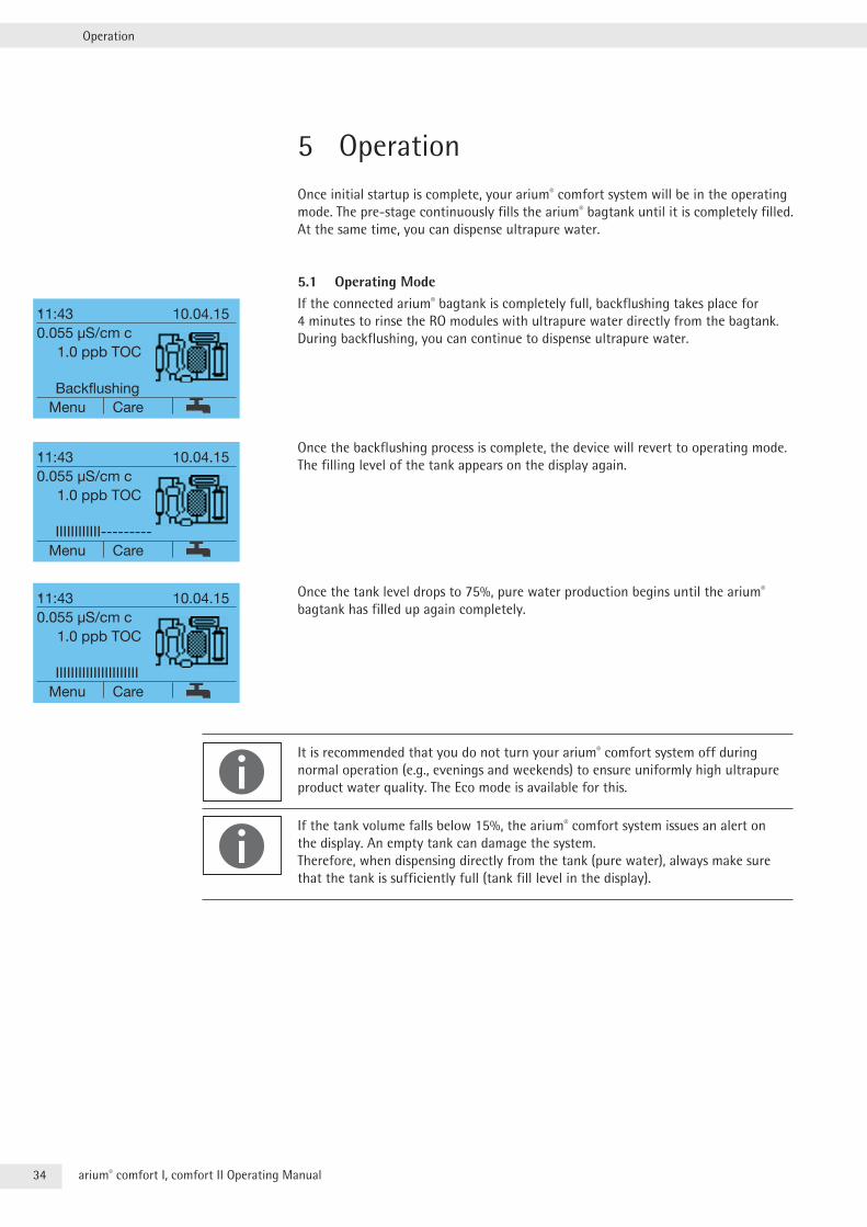
5.1 Operating ModeIf the connected arium® bagtank is completely full, backflushing takes place for 4 minutes to rinse the RO modules with ultrapure water directly from the bagtank . During backflushing, you can continue to dispense ultrapure water .
Once the backflushing process is complete, the device will revert to operating mode . The filling level of the tank appears on the display again .
Once the tank level drops to 75%, pure water production begins until the arium® bagtank has filled up again completely .
It is recommended that you do not turn your arium® comfort system off during normal operation (e .g ., evenings and weekends) to ensure uniformly high ultrapure product water quality . The Eco mode is available for this .
If the tank volume falls below 15%, the arium® comfort system issues an alert on the display . An empty tank can damage the system . Therefore, when dispensing directly from the tank (pure water), always make sure that the tank is sufficiently full (tank fill level in the display) .
11:43 10.04.150.055 µS/cm c 1.0 ppb TOC
Backflushing Menu Care
11:43 10.04.150.055 µS/cm c 1.0 ppb TOC
IIIIIIIIIIII--------- Menu Care
11:43 10.04.150.055 µS/cm c 1.0 ppb TOC
IIIIIIIIIIIIIIIIIIIIII Menu Care
35arium® comfort I, comfort II Operating Manual
Operation
5.2 Dispensing Ultrapure WaterWater can be dispensed manually, volume-controlled or time-controlled .
When dispensing product water, pay attention to the following aspects:
tt Prior to dispensing the water, remove the protective cap on the bell assembly of the final filter .
tt After dispensing the water, replace the protective cap back on the bell assembly .
For applications that require a very low content of organic material before dispensing any water, remove 50 to 100 ml of water from the system (this corresponds to the volume of the supply to the final filter and the final filter capsule) .
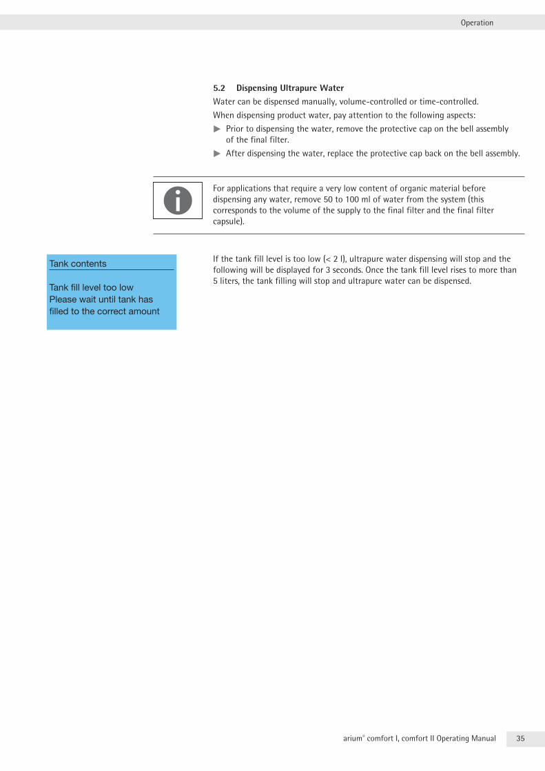
If the tank fill level is too low (< 2 l), ultrapure water dispensing will stop and the following will be displayed for 3 seconds . Once the tank fill level rises to more than 5 liters, the tank filling will stop and ultrapure water can be dispensed .
Tank contents
Tank fill level too lowPlease wait until tank has filled to the correct amount
36 arium® comfort I, comfort II Operating Manual
Operation
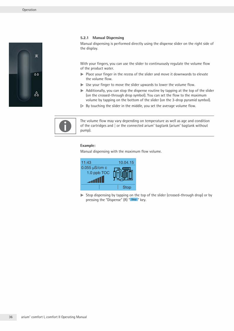
5.2.1 Manual DispensingManual dispensing is performed directly using the dispense slider on the right side of the display .
With your fingers, you can use the slider to continuously regulate the volume flow of the product water .
tt Place your finger in the recess of the slider and move it downwards to elevate the volume flow .
tt Use your finger to move the slider upwards to lower the volume flow .
tt Additionally, you can stop the dispense routine by tapping at the top of the slider (on the crossed-through drop symbol) . You can set the flow to the maximum volume by tapping on the bottom of the slider (on the 3-drop pyramid symbol) .
y By touching the slider in the middle, you set the average volume flow .
The volume flow may vary depending on temperature as well as age and condition of the cartridges and | or the connected arium® bagtank (arium® bagtank without pump) .
Example:Manual dispensing with the maximum flow volume .
11:43 10.04.150.055 µS/cm c 1.0 ppb TOC
Stop
tt Stop dispensing by tapping on the top of the slider (crossed-through drop) or by pressing the “Dispense” (R) “ Stop ” key .
37arium® comfort I, comfort II Operating Manual
Operation
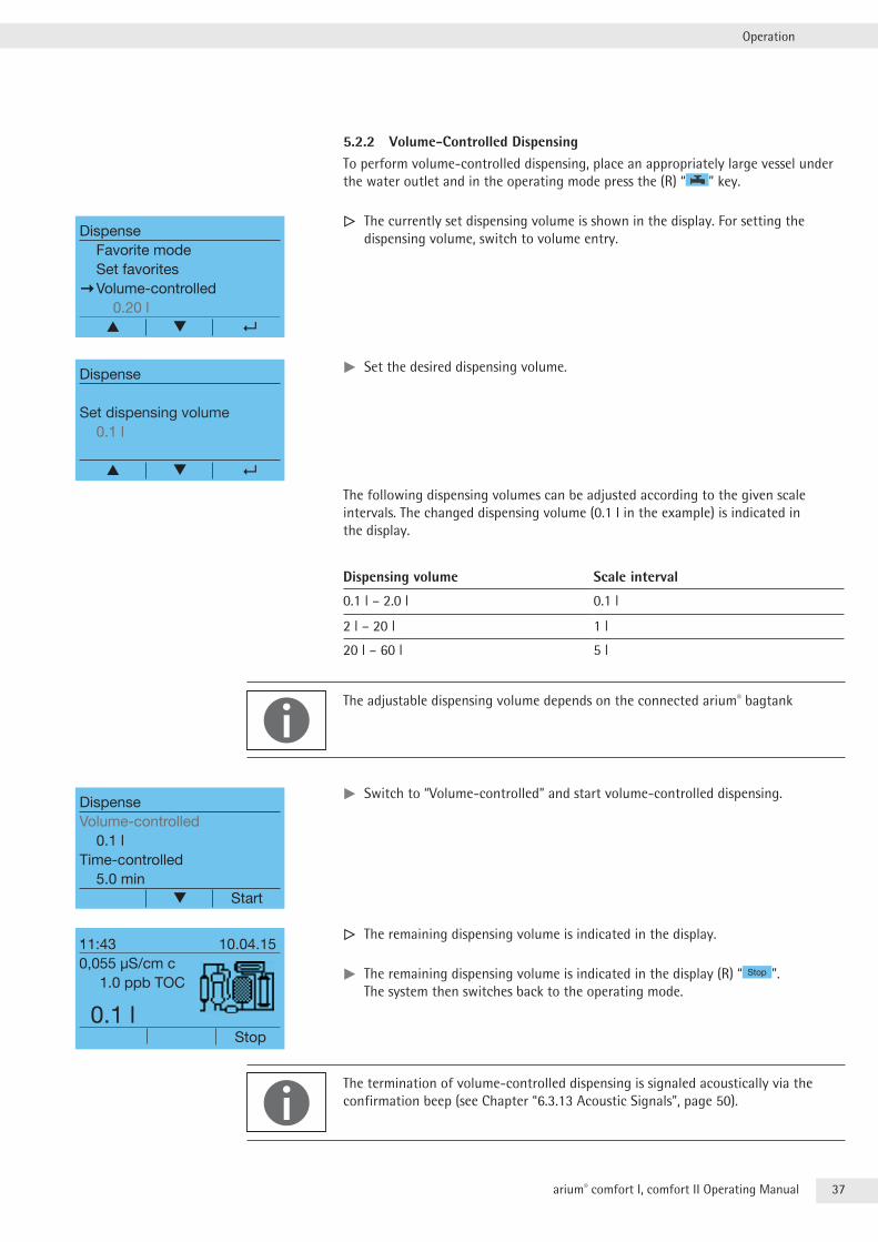
5.2.2 Volume-Controlled DispensingTo perform volume-controlled dispensing, place an appropriately large vessel under the water outlet and in the operating mode press the (R) “ ” key .
y The currently set dispensing volume is shown in the display . For setting the dispensing volume, switch to volume entry .
tt Set the desired dispensing volume .
The following dispensing volumes can be adjusted according to the given scale intervals . The changed dispensing volume (0 .1 l in the example) is indicated in the display .
Dispensing volume Scale interval
0 .1 l – 2 .0 l 0 .1 l
2 l – 20 l 1 l
20 l – 60 l 5 l
The adjustable dispensing volume depends on the connected arium® bagtank
tt Switch to “Volume-controlled” and start volume-controlled dispensing .
y The remaining dispensing volume is indicated in the display .
tt The remaining dispensing volume is indicated in the display (R) “ Stop ” . The system then switches back to the operating mode .
The termination of volume-controlled dispensing is signaled acoustically via the confirmation beep (see Chapter “6 .3 .13 Acoustic Signals”, page 50) .
DispenseFavorite modeSet favorites
Volume-controlled 0.20 l
▲
Dispense
Set dispensing volume0.1 l
▲
DispenseVolume-controlled
0.1 lTime-controlled
5.0 min Start
11:43 10.04.150,055 µS/cm c 1.0 ppb TOC
0.1 l Stop
38 arium® comfort I, comfort II Operating Manual
Operation
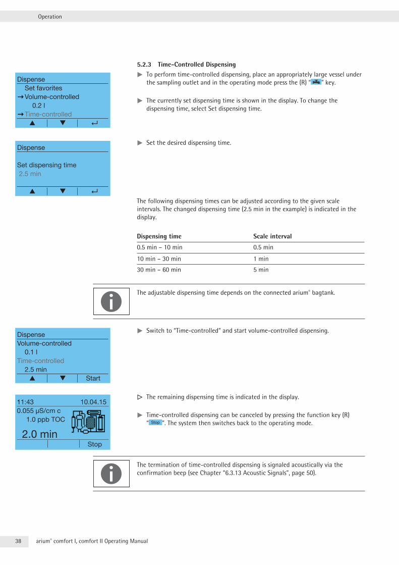
5.2.3 Time-Controlled Dispensingtt To perform time-controlled dispensing, place an appropriately large vessel under the sampling outlet and in the operating mode press the (R) “ ” key .
tt The currently set dispensing time is shown in the display . To change the dispensing time, select Set dispensing time .
tt Set the desired dispensing time .
The following dispensing times can be adjusted according to the given scale intervals . The changed dispensing time (2 .5 min in the example) is indicated in the display .
Dispensing time Scale interval
0 .5 min – 10 min 0 .5 min
10 min – 30 min 1 min
30 min – 60 min 5 min
The adjustable dispensing time depends on the connected arium® bagtank .
tt Switch to “Time-controlled” and start volume-controlled dispensing .
y The remaining dispensing time is indicated in the display .
tt Time-controlled dispensing can be canceled by pressing the function key (R) “ Stop ” . The system then switches back to the operating mode .
The termination of time-controlled dispensing is signaled acoustically via the confirmation beep (see Chapter “6 .3 .13 Acoustic Signals”, page 50) .
Dispense Set favorites Volume-controlled 0.2 l Time-controlled ▲
Dispense
Set dispensing time2.5 min
▲
DispenseVolume-controlled
0.1 lTime-controlled
2.5 min ▲ Start
11:43 10.04.150.055 µS/cm c 1.0 ppb TOC
2.0 min Stop
39arium® comfort I, comfort II Operating Manual
Operation
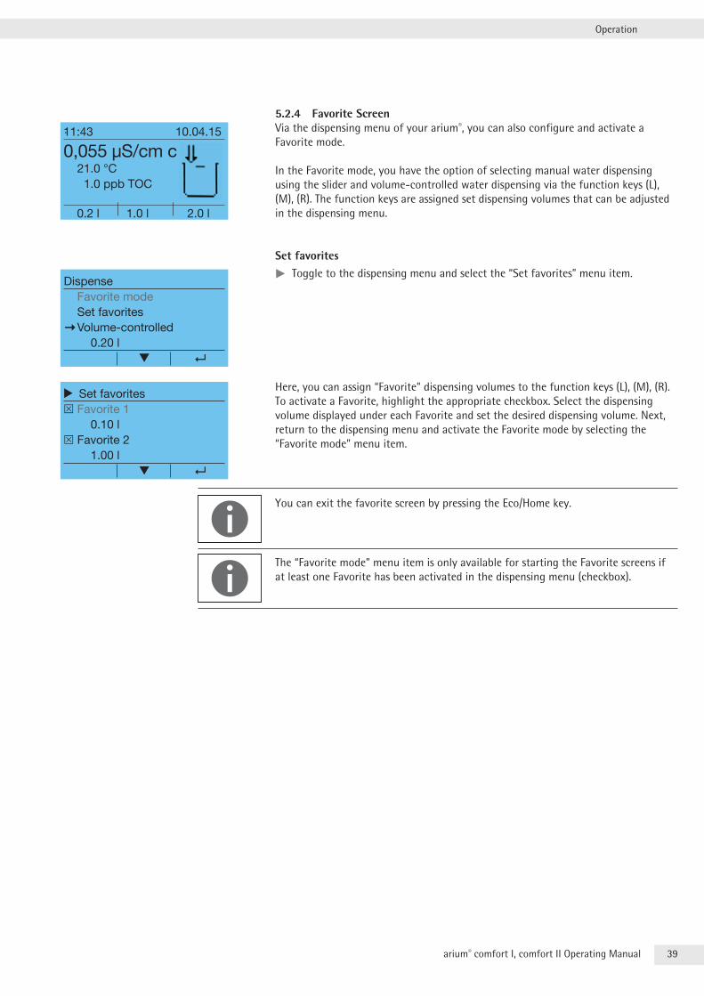
5.2.4 Favorite ScreenVia the dispensing menu of your arium®, you can also configure and activate a Favorite mode .
In the Favorite mode, you have the option of selecting manual water dispensing using the slider and volume-controlled water dispensing via the function keys (L), (M), (R) . The function keys are assigned set dispensing volumes that can be adjusted in the dispensing menu .
Set favoritestt Toggle to the dispensing menu and select the “Set favorites” menu item .
Here, you can assign “Favorite” dispensing volumes to the function keys (L), (M), (R) . To activate a Favorite, highlight the appropriate checkbox . Select the dispensing volume displayed under each Favorite and set the desired dispensing volume . Next, return to the dispensing menu and activate the Favorite mode by selecting the “Favorite mode” menu item .
You can exit the favorite screen by pressing the Eco/Home key .
The “Favorite mode” menu item is only available for starting the Favorite screens if at least one Favorite has been activated in the dispensing menu (checkbox) .
11:43 10.04.15
0,055 µS/cm c 21.0 °C 1.0 ppb TOC
0.2 l 1.0 l 2.0 l
DispenseFavorite modeSet favorites
Volume-controlled 0.20 l
r Set favorites Favorite 1 0.10 l Favorite 2 1.00 l ▼
40 arium® comfort I, comfort II Operating Manual
Operation
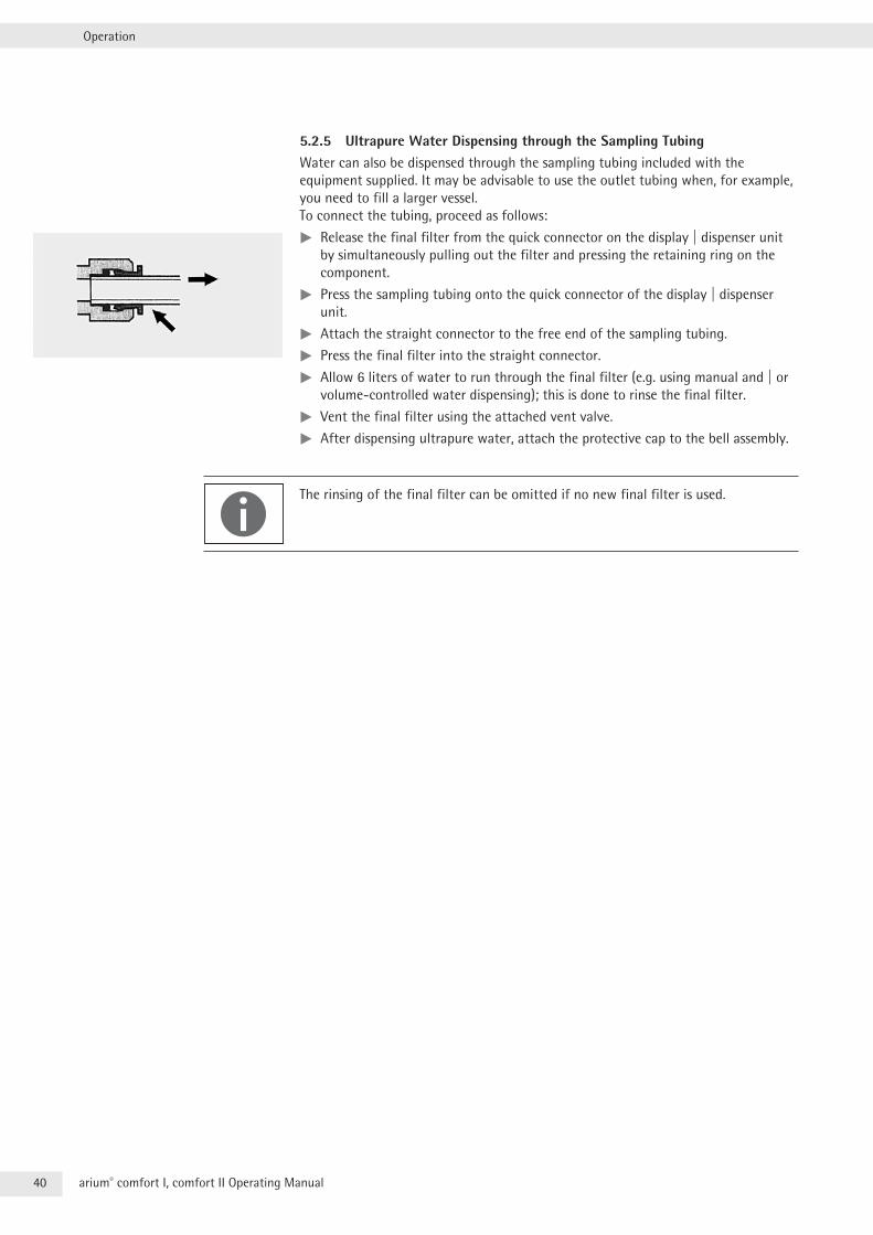
5.2.5 Ultrapure Water Dispensing through the Sampling TubingWater can also be dispensed through the sampling tubing included with the equipment supplied . It may be advisable to use the outlet tubing when, for example, you need to fill a larger vessel . To connect the tubing, proceed as follows:
tt Release the final filter from the quick connector on the display | dispenser unit by simultaneously pulling out the filter and pressing the retaining ring on the component .
tt Press the sampling tubing onto the quick connector of the display | dispenser unit .
tt Attach the straight connector to the free end of the sampling tubing .
tt Press the final filter into the straight connector .
tt Allow 6 liters of water to run through the final filter (e .g . using manual and | or volume-controlled water dispensing); this is done to rinse the final filter .
tt Vent the final filter using the attached vent valve .
tt After dispensing ultrapure water, attach the protective cap to the bell assembly .
The rinsing of the final filter can be omitted if no new final filter is used .
41arium® comfort I, comfort II Operating Manual
System Menu
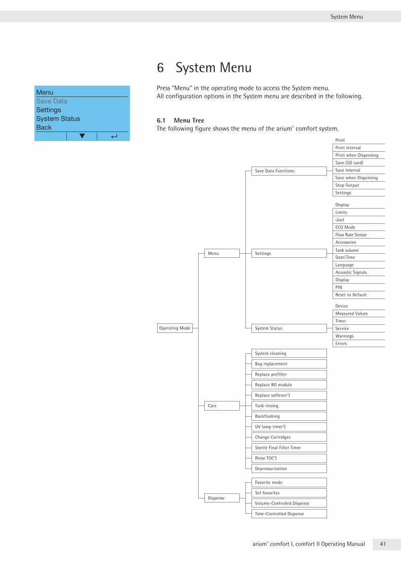
6 System MenuPress “Menu” in the operating mode to access the System menu . All configuration options in the System menu are described in the following .
6.1 Menu TreeThe following figure shows the menu of the arium® comfort system .
PIN
Print Interval
Print when Dispensing
Save (SD card)
Save Interval
Save when Dispensing
Stop Output
Settings
Operating Mode
Menu
Save Data Functions
Settings
System Status
Care
Display
Limits
iJust
ECO Mode
Flow Rate Sensor
Accessories
Tank volume
Date|Time
Language
Acoustic Signals
Display
Reset to Default
Device
Measured Values
Timer
Service
Warnings
Errors
System cleaning
Bag replacement
Replace prefilter
Replace RO module
Replace softener1)
Tank rinsing
Backflushing
UV lamp timer2)
Change Cartridges
Sterile Final Filter Timer
Rinse TOC3)
Depressurization
Dispense
Favorite mode
Set favorites
Volume-Controlled Dispense
Time-Controlled Dispense
MenuSave DataSettingsSystem StatusBack
42 arium® comfort I, comfort II Operating Manual
System Menu
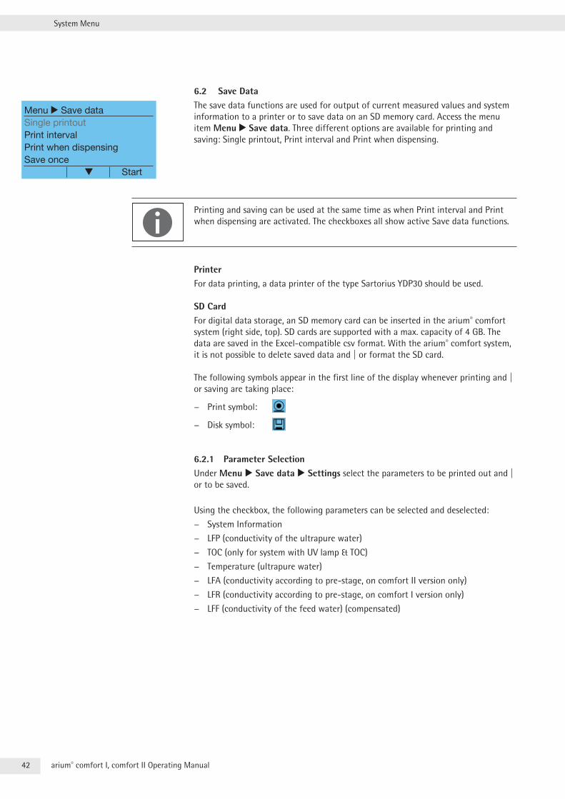
6.2 Save DataThe save data functions are used for output of current measured values and system information to a printer or to save data on an SD memory card . Access the menu item Menu r Save data . Three different options are available for printing and saving: Single printout, Print interval and Print when dispensing .
Printing and saving can be used at the same time as when Print interval and Print when dispensing are activated . The checkboxes all show active Save data functions .
PrinterFor data printing, a data printer of the type Sartorius YDP30 should be used .
SD CardFor digital data storage, an SD memory card can be inserted in the arium® comfort system (right side, top) . SD cards are supported with a max . capacity of 4 GB . The data are saved in the Excel-compatible csv format . With the arium® comfort system, it is not possible to delete saved data and | or format the SD card .
The following symbols appear in the first line of the display whenever printing and | or saving are taking place:
− Print symbol:
− Disk symbol:
6.2.1 Parameter SelectionUnder Menu r Save data r Settings select the parameters to be printed out and | or to be saved .
Using the checkbox, the following parameters can be selected and deselected:
− System Information
− LFP (conductivity of the ultrapure water)
− TOC (only for system with UV lamp & TOC)
− Temperature (ultrapure water)
− LFA (conductivity according to pre-stage, on comfort II version only)
− LFR (conductivity according to pre-stage, on comfort I version only)
− LFF (conductivity of the feed water) (compensated)
Menu r Save dataSingle printoutPrint intervalPrint when dispensingSave once Start
43arium® comfort I, comfort II Operating Manual
System Menu
6.2.2 Single-item SaveTo start a Single printout and | or Save once procedure, select under Menu r Save data the item Single printout and | or Save once . The selected parameters are output . Afterwards, the system switches to the operating mode .
6.2.3 Save IntervalTo access the Print interval and | or Save interval functions, highlight the appropriate checkbox under Menu r Save data . In the Menu r Save data r Settings, the interval can be adjusted within a range of 1 to 60 minutes . This applies to data printing and to digital storage on the SD card .
6.2.4 Save when DispensingTo access the Print when dispensing and | or Save when dispensing functions, highlight the appropriate checkbox under Menu r Save data . As soon as the arium® comfort system dispenses ultrapure water, the data are saved on the selected medium .
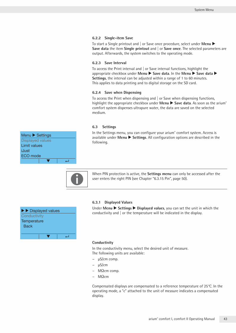
6.3 SettingsIn the Settings menu, you can configure your arium® comfort system . Access is available under Menu r Settings . All configuration options are described in the following .
When PIN protection is active, the Settings menu can only be accessed after the user enters the right PIN (see Chapter “6 .3 .15 Pin”, page 50) .
6.3.1 Displayed ValuesUnder Menu r Settings r Displayed values, you can set the unit in which the conductivity and | or the temperature will be indicated in the display .
ConductivityIn the conductivity menu, select the desired unit of measure . The following units are available:
− µS/cm comp .
− µS/cm
− MOcm comp .
− MOcm
Compensated displays are compensated to a reference temperature of 25°C . In the operating mode, a “c” attached to the unit of measure indicates a compensated display .
Menu r SettingsDisplayed valuesLimit valuesiJustECO mode
r r Displayed valuesConductivityTemperature Back
44 arium® comfort I, comfort II Operating Manual
System Menu
If no valid conductivity value exists, the unit of measure will flash . This can take place, for example, after exiting the ECO mode . The flashing display indicates that a conductivity measurement is being performed . The measurement takes a minute at the most .
In the vernacular of the arium® comfort system, the term “conductivity” (unit: µS/cm) is synonymous with “specific resistivity” (unit: MOcm) .
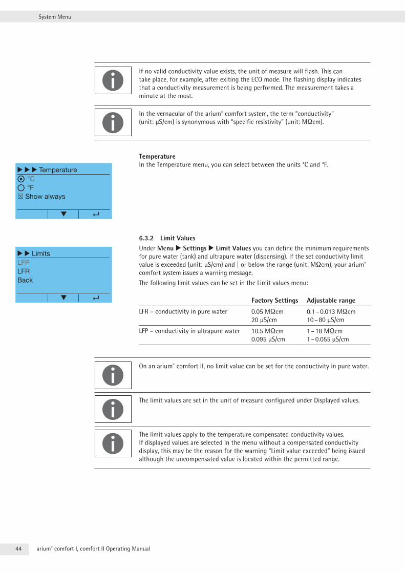
TemperatureIn the Temperature menu, you can select between the units °C and °F .
6.3.2 Limit ValuesUnder Menu r Settings r Limit Values you can define the minimum requirements for pure water (tank) and ultrapure water (dispensing) . If the set conductivity limit value is exceeded (unit: µS/cm) and | or below the range (unit: MOcm), your arium® comfort system issues a warning message .
The following limit values can be set in the Limit values menu:
Factory Settings Adjustable range
LFR – conductivity in pure water 0 .05 MOcm 20 µS/cm
0 .1 – 0 .013 MOcm 10 – 80 µS/cm
LFP – conductivity in ultrapure water 10 .5 MOcm 0 .095 µS/cm
1 – 18 MOcm 1 – 0 .055 µS/cm
On an arium® comfort II, no limit value can be set for the conductivity in pure water .
The limit values are set in the unit of measure configured under Displayed values .
The limit values apply to the temperature compensated conductivity values . If displayed values are selected in the menu without a compensated conductivity display, this may be the reason for the warning “Limit value exceeded” being issued although the uncompensated value is located within the permitted range .
r r r Temperature
°C
°F Show always
r r LimitsLFPLFRBack
45arium® comfort I, comfort II Operating Manual
System Menu
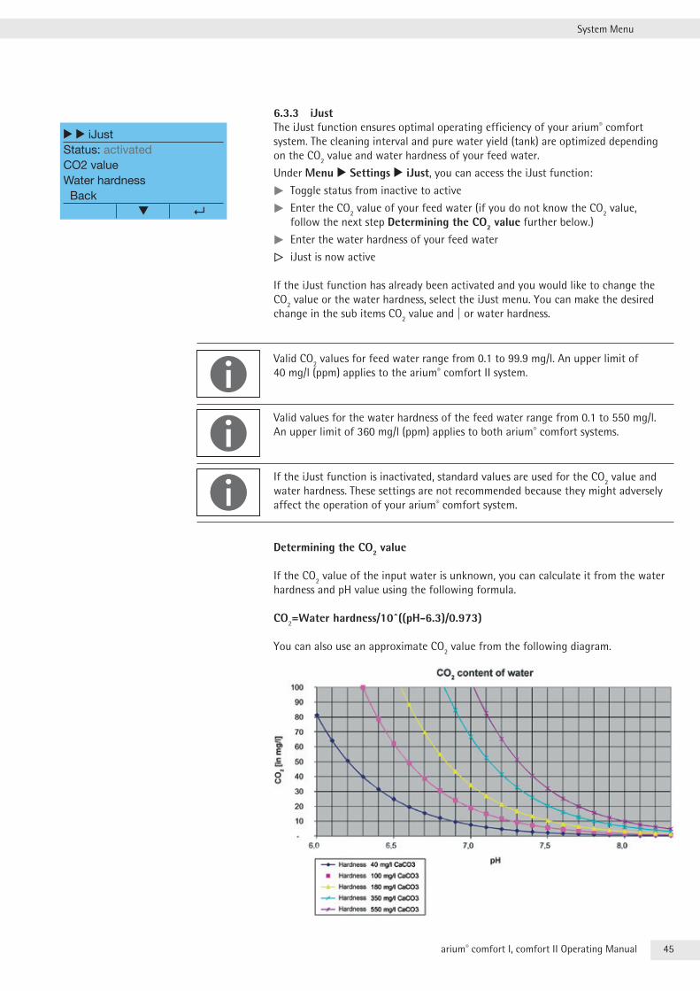
6.3.3 iJustThe iJust function ensures optimal operating efficiency of your arium® comfort system . The cleaning interval and pure water yield (tank) are optimized depending on the CO2 value and water hardness of your feed water .
Under Menu r Settings r iJust, you can access the iJust function:
tt Toggle status from inactive to active
tt Enter the CO2 value of your feed water (if you do not know the CO2 value, follow the next step Determining the CO2 value further below .)
tt Enter the water hardness of your feed water
y iJust is now active
If the iJust function has already been activated and you would like to change the CO2 value or the water hardness, select the iJust menu . You can make the desired change in the sub items CO2 value and | or water hardness .
Valid CO2 values for feed water range from 0 .1 to 99 .9 mg/l . An upper limit of 40 mg/l (ppm) applies to the arium® comfort II system .
Valid values for the water hardness of the feed water range from 0 .1 to 550 mg/l . An upper limit of 360 mg/l (ppm) applies to both arium® comfort systems .
If the iJust function is inactivated, standard values are used for the CO2 value and water hardness . These settings are not recommended because they might adversely affect the operation of your arium® comfort system .
Determining the CO2 value
If the CO2 value of the input water is unknown, you can calculate it from the water hardness and pH value using the following formula .
CO2=Water hardness/10^((pH-6.3)/0.973)
You can also use an approximate CO2 value from the following diagram .
r r iJustStatus: activatedCO2 valueWater hardness Back
46 arium® comfort I, comfort II Operating Manual
System Menu
Sartorius recommends using test sticks to determine the water hardness . A suitable pH meter should be used to measure the pH value . You can also determine the CO2 content using a CO2 quick test .
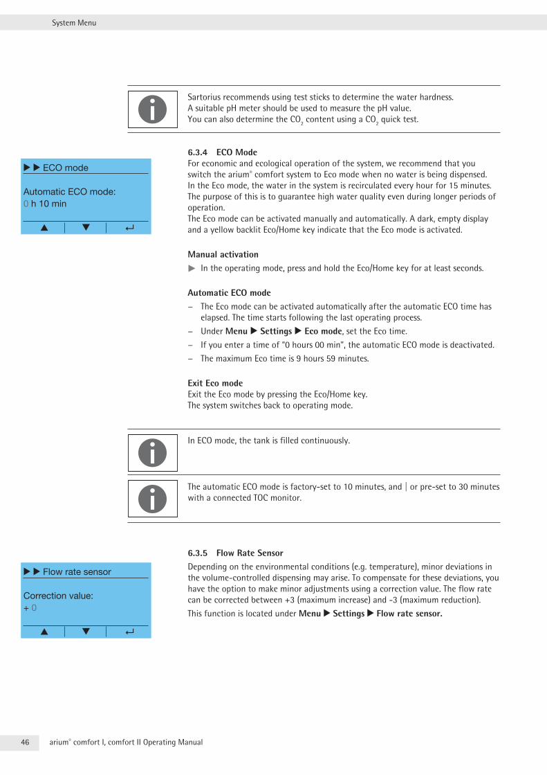
6.3.4 ECO ModeFor economic and ecological operation of the system, we recommend that you switch the arium® comfort system to Eco mode when no water is being dispensed . In the Eco mode, the water in the system is recirculated every hour for 15 minutes . The purpose of this is to guarantee high water quality even during longer periods of operation . The Eco mode can be activated manually and automatically . A dark, empty display and a yellow backlit Eco/Home key indicate that the Eco mode is activated .
Manual activationtt In the operating mode, press and hold the Eco/Home key for at least seconds .
Automatic ECO mode − The Eco mode can be activated automatically after the automatic ECO time has
elapsed . The time starts following the last operating process .
− Under Menu r Settings r Eco mode, set the Eco time .
− If you enter a time of “0 hours 00 min”, the automatic ECO mode is deactivated .
− The maximum Eco time is 9 hours 59 minutes .
Exit Eco mode Exit the Eco mode by pressing the Eco/Home key . The system switches back to operating mode .
In ECO mode, the tank is filled continuously .
The automatic ECO mode is factory-set to 10 minutes, and | or pre-set to 30 minutes with a connected TOC monitor .
6.3.5 Flow Rate SensorDepending on the environmental conditions (e .g . temperature), minor deviations in the volume-controlled dispensing may arise . To compensate for these deviations, you have the option to make minor adjustments using a correction value . The flow rate can be corrected between +3 (maximum increase) and -3 (maximum reduction) .
This function is located under Menu r Settings r Flow rate sensor.
r r ECO mode
Automatic ECO mode:0 h 10 min
▲
r r Flow rate sensor
Correction value:+ 0
▲
47arium® comfort I, comfort II Operating Manual
System Menu
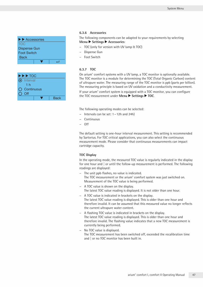
6.3.6 AccessoriesThe following components can be adapted to your requirements by selecting Menu r Settings r Accessories:
− TOC (only for version with UV lamp & TOC)
− Dispense Gun
− Foot Switch
6.3.7 TOCOn arium® comfort systems with a UV lamp, a TOC monitor is optionally available . The TOC monitor is a module for determining the TOC (Total Organic Carbon) content of ultrapure water . The measuring range of the TOC monitor is ppb (parts per billion) . The measuring principle is based on UV oxidation and a conductivity measurement .
If your arium® comfort system is equipped with a TOC monitor, you can configure the TOC measurement under Menu r Settings r TOC .
The following operating modes can be selected:
− Intervals can be set: 1 – 12h and 24h)
− Continuous
− Off
The default setting is one-hour interval measurement . This setting is recommended by Sartorius . For TOC critical applications, you can also select the continuous measurement mode . Please consider that continuous measurements can impact cartridge capacity .
TOC DisplayIn the operating mode, the measured TOC value is regularly indicated in the display for one hour and | or until the follow-up measurement is performed . The following readings are displayed:
− The unit ppb flashes, no value is indicated . The TOC measurement or the arium® comfort system was just switched on . Measurement of the TOC value is being performed .
− A TOC value is shown on the display . The latest TOC value reading is displayed . It is not older than one hour .
− A TOC value is indicated in brackets on the display . The latest TOC value reading is displayed . This is older than one hour and therefore invalid . It can be assumed that this measured value no longer reflects the current ultrapure water content .
− A flashing TOC value is indicated in brackets on the display . The latest TOC value reading is displayed . This is older than one hour and therefore invalid . The flashing value indicates that a new TOC measurement is currently being performed .
− No TOC value is displayed . The TOC measurement has been switched off, exceeded the recalibration time and | or no TOC monitor has been built in .
r r AccessoriesTOCDispense GunFoot SwitchBack
r r r TOC
Interval 1 h
Continuous
Off Back
48 arium® comfort I, comfort II Operating Manual
System Menu
Recalibrating the TOC MonitorThe TOC monitor is equipped with a UV radiator . This UV radiator is subject to ageing and must be replaced at regular intervals . To ensure accurate TOC measurements after replacing the UV radiator, the TOC monitor must be recalibrated by Sartorius Service .
The normal service interval for recalibration is one year . If your TOC measurements are more frequent, the UV radiator ages faster . This is the case when continuous measurements are performed and the arium® comfort system is in frequent use . In such cases, earlier recalibration may be required .
Your arium® comfort system issues warning message at the intervals 6, 4, 2 weeks as soon as recalibration is required . For recalibration, please contact Sartorius Service .
If the service interval for the TOC monitor has expired (at least after a year), the TOC monitor on your arium® comfort system will be deactivated . You cannot measure TOC again until after recalibration . Ultrapure water can continue to be dispensed .
The arium® comfort system alerts the recalibration of the TOC monitor at the intervals 6, 4, 2 weeks . Please inform your service technician after the first message .
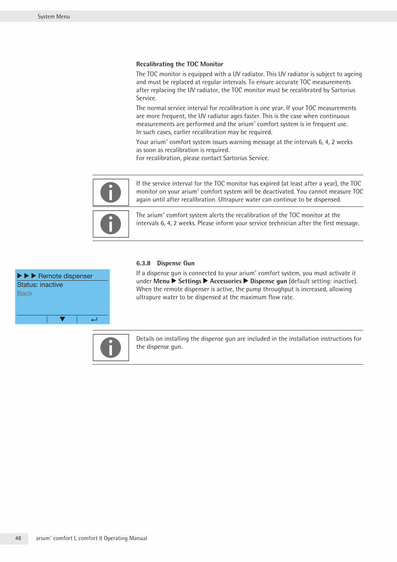
6.3.8 Dispense GunIf a dispense gun is connected to your arium® comfort system, you must activate it under Menu r Settings r Accessories r Dispense gun (default setting: inactive) . When the remote dispenser is active, the pump throughput is increased, allowing ultrapure water to be dispensed at the maximum flow rate .
Details on installing the dispense gun are included in the installation instructions for the dispense gun .
r r r Remote dispenserStatus: inactiveBack
49arium® comfort I, comfort II Operating Manual
System Menu
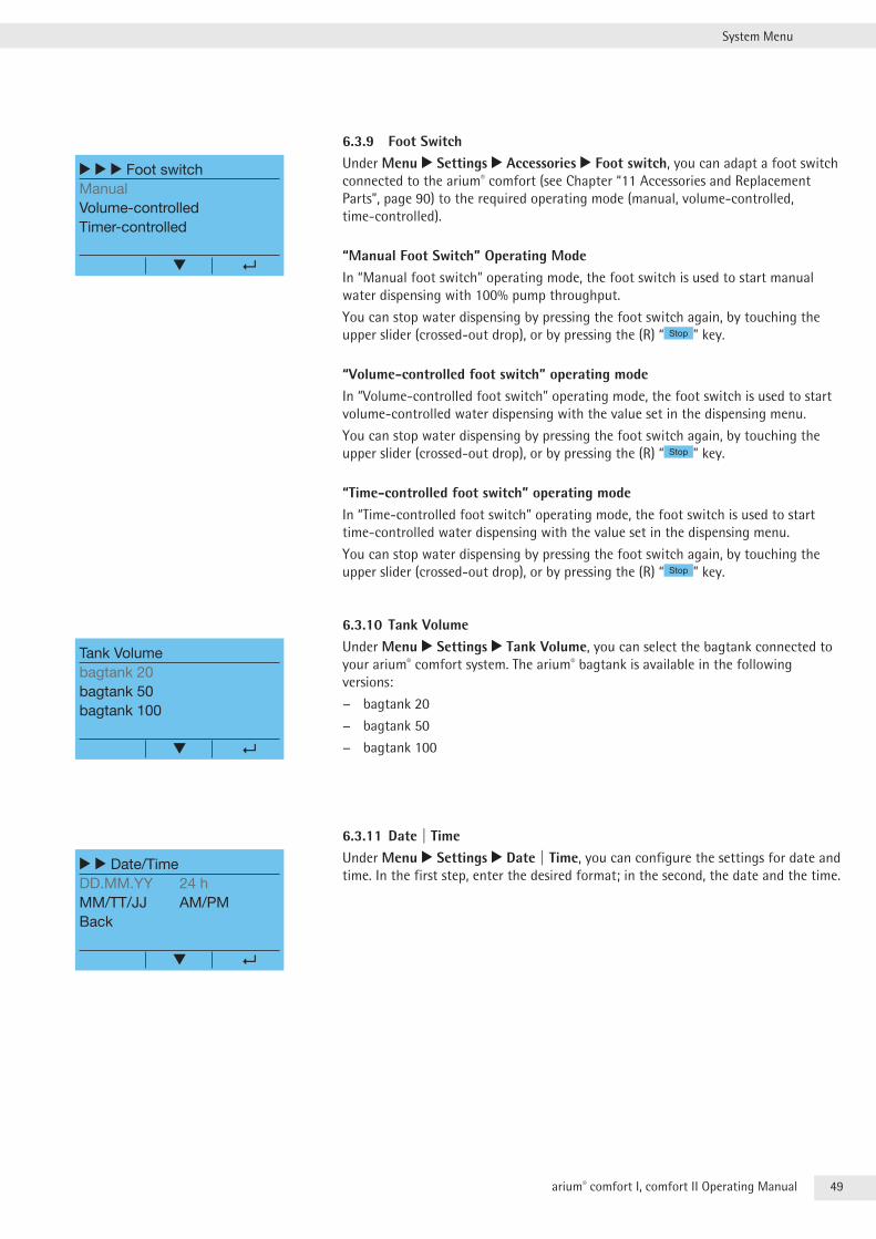
6.3.9 Foot SwitchUnder Menu r Settings r Accessories r Foot switch, you can adapt a foot switch connected to the arium® comfort (see Chapter “11 Accessories and Replacement Parts”, page 90) to the required operating mode (manual, volume-controlled, time-controlled) .
“Manual Foot Switch” Operating ModeIn “Manual foot switch” operating mode, the foot switch is used to start manual water dispensing with 100% pump throughput .
You can stop water dispensing by pressing the foot switch again, by touching the upper slider (crossed-out drop), or by pressing the (R) “ Stop ” key .
“Volume-controlled foot switch” operating modeIn “Volume-controlled foot switch” operating mode, the foot switch is used to start volume-controlled water dispensing with the value set in the dispensing menu .
You can stop water dispensing by pressing the foot switch again, by touching the upper slider (crossed-out drop), or by pressing the (R) “ Stop ” key .
“Time-controlled foot switch” operating modeIn “Time-controlled foot switch” operating mode, the foot switch is used to start time-controlled water dispensing with the value set in the dispensing menu .
You can stop water dispensing by pressing the foot switch again, by touching the upper slider (crossed-out drop), or by pressing the (R) “ Stop ” key .
6.3.10 Tank VolumeUnder Menu r Settings r Tank Volume, you can select the bagtank connected to your arium® comfort system . The arium® bagtank is available in the following versions:
− bagtank 20
− bagtank 50
− bagtank 100
6.3.11 Date | TimeUnder Menu r Settings r Date | Time, you can configure the settings for date and time . In the first step, enter the desired format; in the second, the date and the time .
r r r Foot switchManualVolume-controlledTimer-controlled
Tank Volumebagtank 20bagtank 50bagtank 100
r r Date/TimeDD.MM.YY 24 hMM/TT/JJ AM/PMBack
50 arium® comfort I, comfort II Operating Manual
System Menu
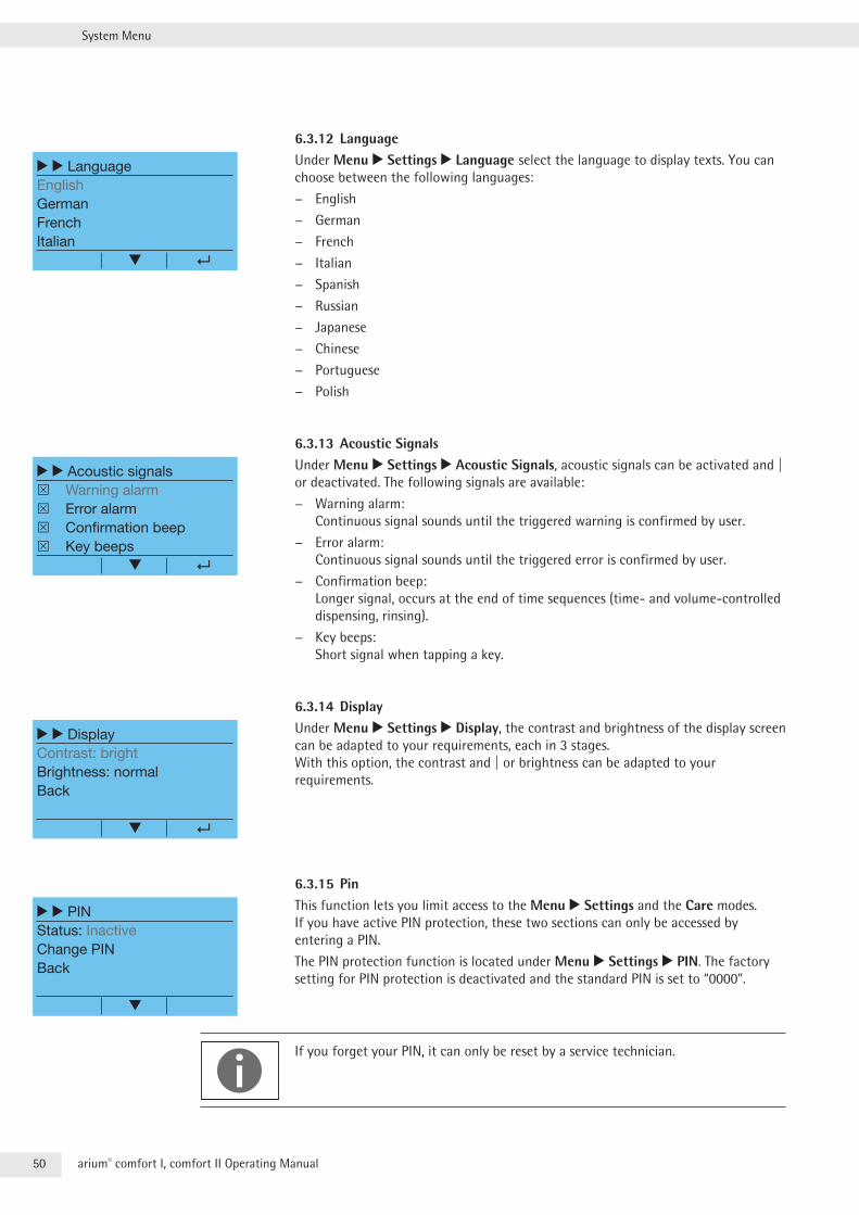
6.3.12 LanguageUnder Menu r Settings r Language select the language to display texts . You can choose between the following languages:
− English
− German
− French
− Italian
− Spanish
− Russian
− Japanese
− Chinese
− Portuguese
− Polish
6.3.13 Acoustic SignalsUnder Menu r Settings r Acoustic Signals, acoustic signals can be activated and | or deactivated . The following signals are available:
− Warning alarm: Continuous signal sounds until the triggered warning is confirmed by user .
− Error alarm: Continuous signal sounds until the triggered error is confirmed by user .
− Confirmation beep: Longer signal, occurs at the end of time sequences (time- and volume-controlled dispensing, rinsing) .
− Key beeps: Short signal when tapping a key .
6.3.14 DisplayUnder Menu r Settings r Display, the contrast and brightness of the display screen can be adapted to your requirements, each in 3 stages . With this option, the contrast and | or brightness can be adapted to your requirements .
6.3.15 PinThis function lets you limit access to the Menu r Settings and the Care modes . If you have active PIN protection, these two sections can only be accessed by entering a PIN .
The PIN protection function is located under Menu r Settings r PIN . The factory setting for PIN protection is deactivated and the standard PIN is set to “0000” .
If you forget your PIN, it can only be reset by a service technician .
r r LanguageEnglishGermanFrenchItalian
r r Acoustic signals Warning alarm Error alarm Confirmation beep Key beeps
r r DisplayContrast: brightBrightness: normalBack
r r PINStatus: InactiveChange PINBack
51arium® comfort I, comfort II Operating Manual
System Menu
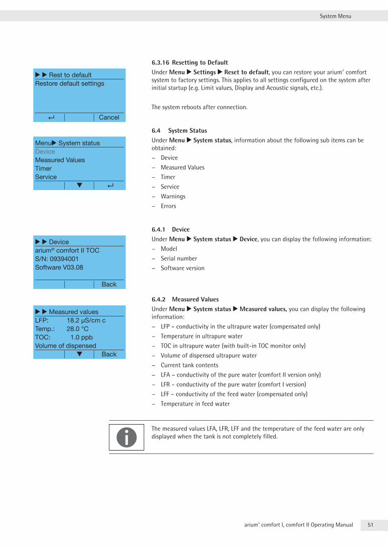
6.3.16 Resetting to DefaultUnder Menu r Settings r Reset to default, you can restore your arium® comfort system to factory settings . This applies to all settings configured on the system after initial startup (e .g . Limit values, Display and Acoustic signals, etc .) .
The system reboots after connection .
6.4 System StatusUnder Menu r System status, information about the following sub items can be obtained:
− Device
− Measured Values
− Timer
− Service
− Warnings
− Errors
6.4.1 DeviceUnder Menu r System status r Device, you can display the following information:
− Model
− Serial number
− Software version
6.4.2 Measured ValuesUnder Menu r System status r Measured values, you can display the following information:
− LFP – conductivity in the ultrapure water (compensated only)
− Temperature in ultrapure water
− TOC in ultrapure water (with built-in TOC monitor only)
− Volume of dispensed ultrapure water
− Current tank contents
− LFA – conductivity of the pure water (comfort II version only)
− LFR – conductivity of the pure water (comfort I version)
− LFF – conductivity of the feed water (compensated only)
− Temperature in feed water
The measured values LFA, LFR, LFF and the temperature of the feed water are only displayed when the tank is not completely filled .
r r Rest to defaultRestore default settings
Cancel
Menur System statusDeviceMeasured ValuesTimerService
r r Devicearium® comfort II TOCS/N: 09394001Software V03.08
Back
r r Measured valuesLFP: 18.2 µS/cm cTemp.: 28.0 °CTOC: 1.0 ppbVolume of dispensed Back
52 arium® comfort I, comfort II Operating Manual
System Menu
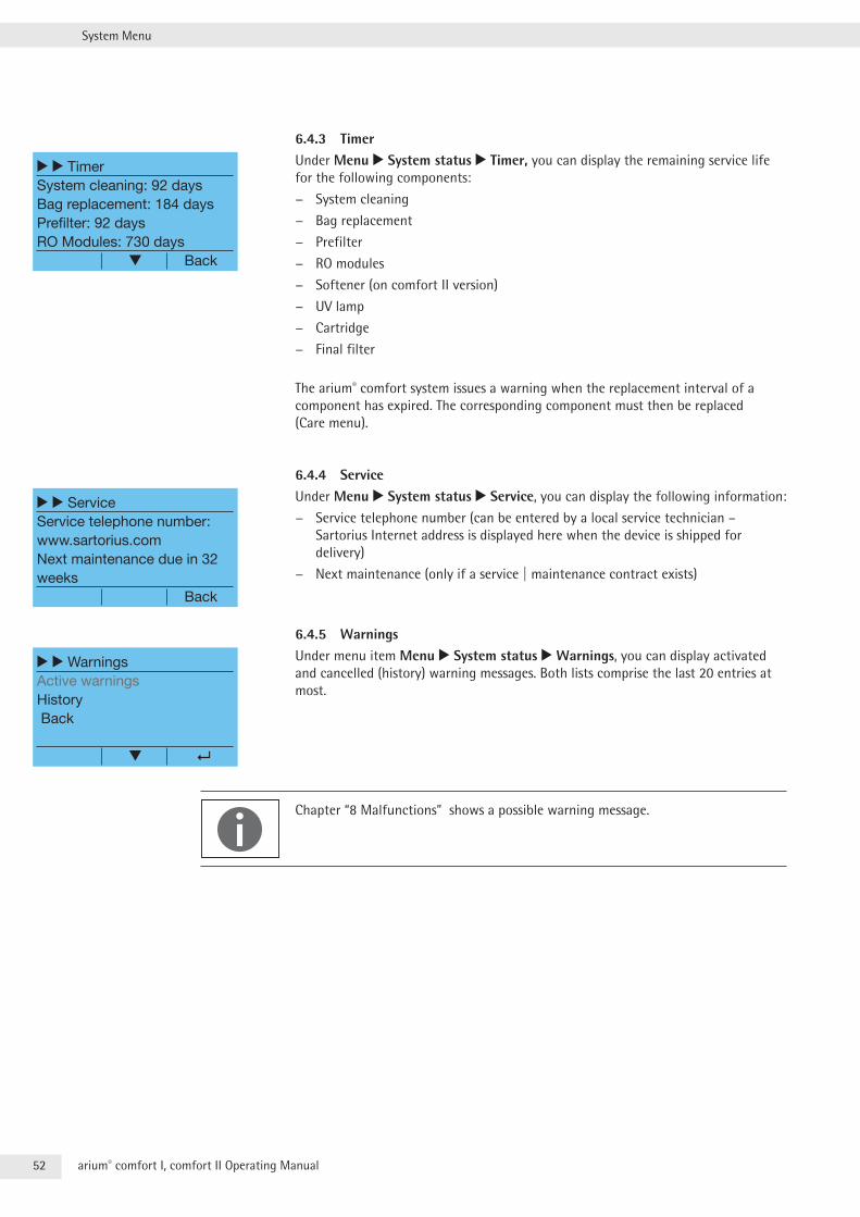
6.4.3 TimerUnder Menu r System status r Timer, you can display the remaining service life for the following components:
− System cleaning
− Bag replacement
− Prefilter
− RO modules
− Softener (on comfort II version)
− UV lamp
− Cartridge
− Final filter
The arium® comfort system issues a warning when the replacement interval of a component has expired . The corresponding component must then be replaced (Care menu) .
6.4.4 ServiceUnder Menu r System status r Service, you can display the following information:
− Service telephone number (can be entered by a local service technician – Sartorius Internet address is displayed here when the device is shipped for delivery)
− Next maintenance (only if a service | maintenance contract exists)
6.4.5 WarningsUnder menu item Menu r System status r Warnings, you can display activated and cancelled (history) warning messages . Both lists comprise the last 20 entries at most .
Chapter “8 Malfunctions” shows a possible warning message .
r r TimerSystem cleaning: 92 daysBag replacement: 184 daysPrefilter: 92 daysRO Modules: 730 days Back
r r ServiceService telephone number:www.sartorius.comNext maintenance due in 32 weeks Back
r r WarningsActive warningsHistory Back
53arium® comfort I, comfort II Operating Manual
System Menu
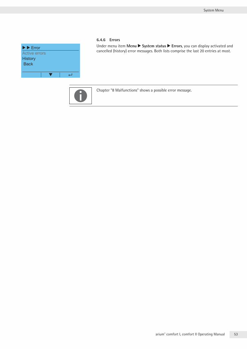
6.4.6 ErrorsUnder menu item Menu r System status r Errors, you can display activated and cancelled (history) error messages . Both lists comprise the last 20 entries at most .
Chapter “8 Malfunctions” shows a possible error message .
r r ErrorActive errorsHistory Back
54 arium® comfort I, comfort II Operating Manual
Care and Maintenance
7 Care and MaintenanceThe main menu Care contains the maintenance section for your system .
You have access to the following options:
− Start system cleaning
− Start bag replacement
− Replace prefilter
− Replace RO module(s)
− Replace softener (on comfort II version)
− Tank rinsing
− Backflushing
− UV lamp timer (for system with UV lamp)
− Changing cartridge
− Sterile final filter timer
− TOC rinse (for system with UV lamp & TOC)
− Depressurization
When PIN protection is active, the Care menu can only be accessed after the user enters the right PIN .
The Care function is primarily designed to help you keep your arium® comfort system free of contamination and guarantee consistent water quality . For example, bacterial growth and the biofilm that can build up within the modules and lines are prevented .
The frequency of care procedures necessary for the system depends on:
− The quality of the feed water (tap water)
− Pure water quality requirements (tank)
− Ultrapure water consumption
The arium® comfort system issues a warning when the care interval of a component has expired . The color of the display then turns yellow (active warning) . Once the appropriate care has been performed, the interval is reset and the warning deactivated .
CareStart system cleaningStart bag replacementReplace prefilterReplace RO module(s)
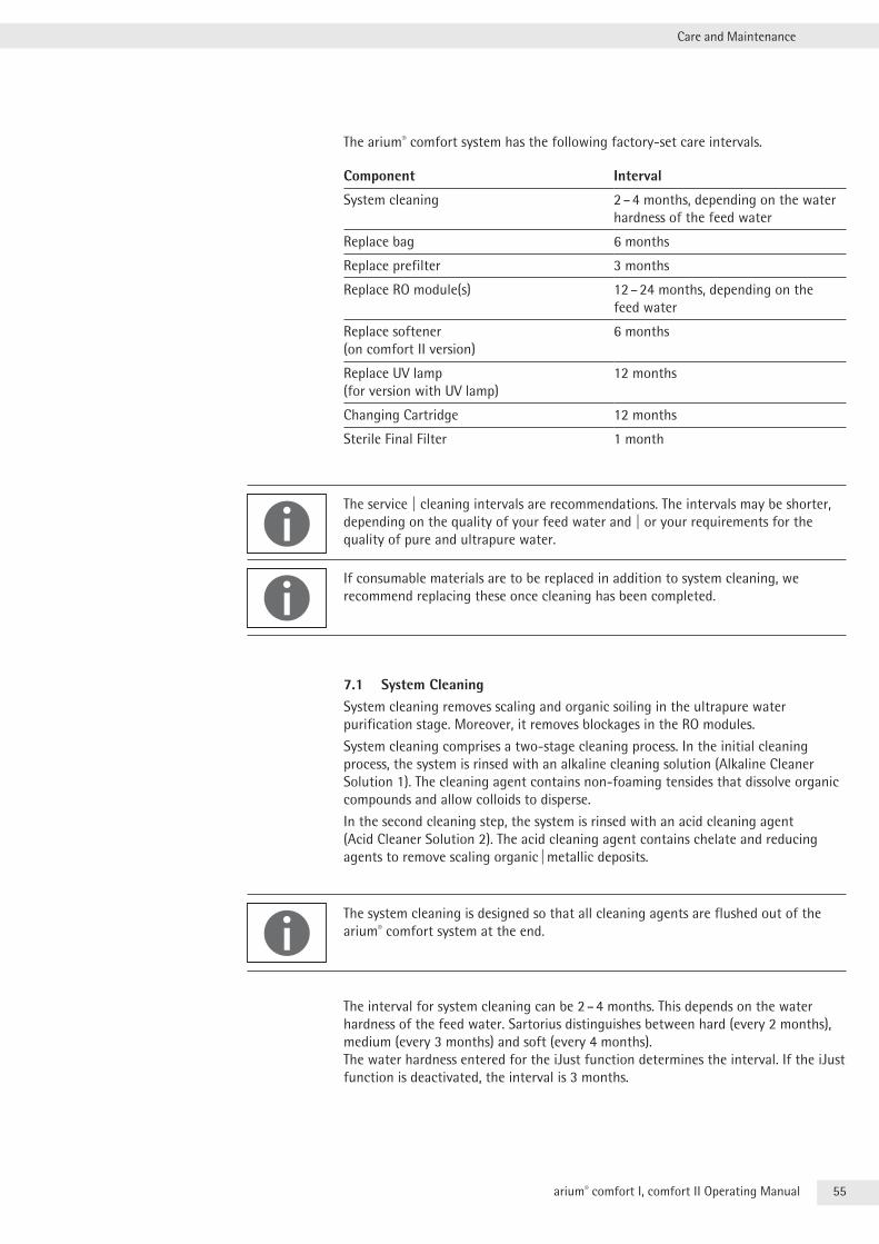
55arium® comfort I, comfort II Operating Manual
Care and Maintenance
The arium® comfort system has the following factory-set care intervals .
Component Interval
System cleaning 2 – 4 months, depending on the water hardness of the feed water
Replace bag 6 months
Replace prefilter 3 months
Replace RO module(s) 12 – 24 months, depending on the feed water
Replace softener (on comfort II version)
6 months
Replace UV lamp (for version with UV lamp)
12 months
Changing Cartridge 12 months
Sterile Final Filter 1 month
The service | cleaning intervals are recommendations . The intervals may be shorter, depending on the quality of your feed water and | or your requirements for the quality of pure and ultrapure water .
If consumable materials are to be replaced in addition to system cleaning, we recommend replacing these once cleaning has been completed .
7.1 System CleaningSystem cleaning removes scaling and organic soiling in the ultrapure water purification stage . Moreover, it removes blockages in the RO modules .
System cleaning comprises a two-stage cleaning process . In the initial cleaning process, the system is rinsed with an alkaline cleaning solution (Alkaline Cleaner Solution 1) . The cleaning agent contains non-foaming tensides that dissolve organic compounds and allow colloids to disperse .
In the second cleaning step, the system is rinsed with an acid cleaning agent (Acid Cleaner Solution 2) . The acid cleaning agent contains chelate and reducing agents to remove scaling organic | metallic deposits .
The system cleaning is designed so that all cleaning agents are flushed out of the arium® comfort system at the end .
The interval for system cleaning can be 2 – 4 months . This depends on the water hardness of the feed water . Sartorius distinguishes between hard (every 2 months), medium (every 3 months) and soft (every 4 months) . The water hardness entered for the iJust function determines the interval . If the iJust function is deactivated, the interval is 3 months .
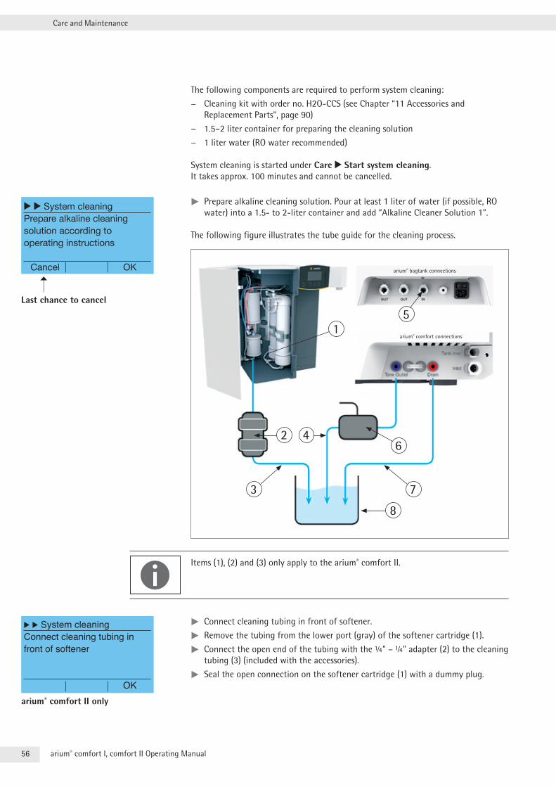
56 arium® comfort I, comfort II Operating Manual
Care and Maintenance
The following components are required to perform system cleaning:
− Cleaning kit with order no . H2O-CCS (see Chapter “11 Accessories and Replacement Parts”, page 90)
− 1 .5–2 liter container for preparing the cleaning solution
− 1 liter water (RO water recommended)
System cleaning is started under Care r Start system cleaning . It takes approx . 100 minutes and cannot be cancelled .
tt Prepare alkaline cleaning solution . Pour at least 1 liter of water (if possible, RO water) into a 1 .5- to 2-liter container and add “Alkaline Cleaner Solution 1” .
The following figure illustrates the tube guide for the cleaning process .
Items (1), (2) and (3) only apply to the arium® comfort II .
tt Connect cleaning tubing in front of softener .
tt Remove the tubing from the lower port (gray) of the softener cartridge (1) .
tt Connect the open end of the tubing with the ¼” – ¼” adapter (2) to the cleaning tubing (3) (included with the accessories) .
tt Seal the open connection on the softener cartridge (1) with a dummy plug .
r r System cleaningPrepare alkaline cleaning solution according to operating instructions
Cancel OK
Last chance to cancel
15
2 46
7
8
3
arium® comfort connections
arium® bagtank connections
r r System cleaningConnect cleaning tubing in front of softener
OKarium® comfort II only
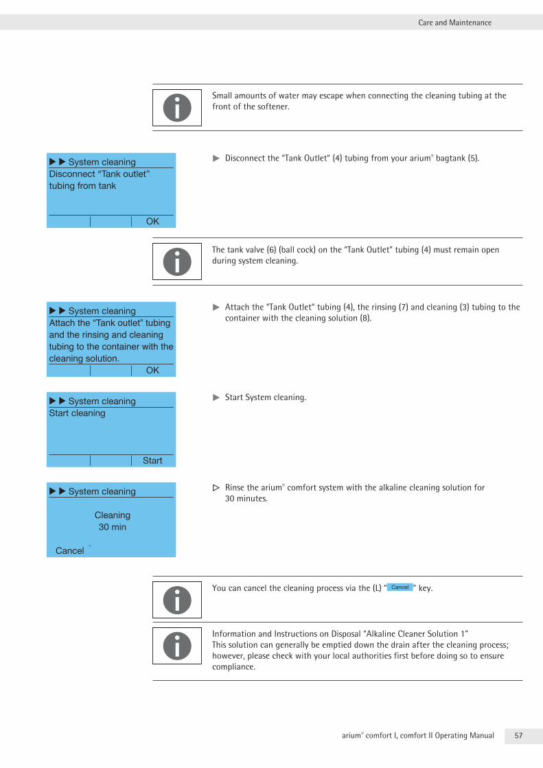
57arium® comfort I, comfort II Operating Manual
Care and Maintenance
Small amounts of water may escape when connecting the cleaning tubing at the front of the softener .
tt Disconnect the “Tank Outlet“ (4) tubing from your arium® bagtank (5) .
The tank valve (6) (ball cock) on the “Tank Outlet” tubing (4) must remain open during system cleaning .
tt Attach the “Tank Outlet“ tubing (4), the rinsing (7) and cleaning (3) tubing to the container with the cleaning solution (8) .
tt Start System cleaning .
y Rinse the arium® comfort system with the alkaline cleaning solution for 30 minutes .
You can cancel the cleaning process via the (L) “ Cancel ” key .
Information and Instructions on Disposal “Alkaline Cleaner Solution 1” This solution can generally be emptied down the drain after the cleaning process; however, please check with your local authorities first before doing so to ensure compliance .
r r System cleaningDisconnect “Tank outlet” tubing from tank
OK
r r System cleaningAttach the “Tank outlet” tubing and the rinsing and cleaning tubing to the container with the cleaning solution. OK
r r System cleaningStart cleaning
Start
r r System cleaning
Cleaning30 min
Cancel
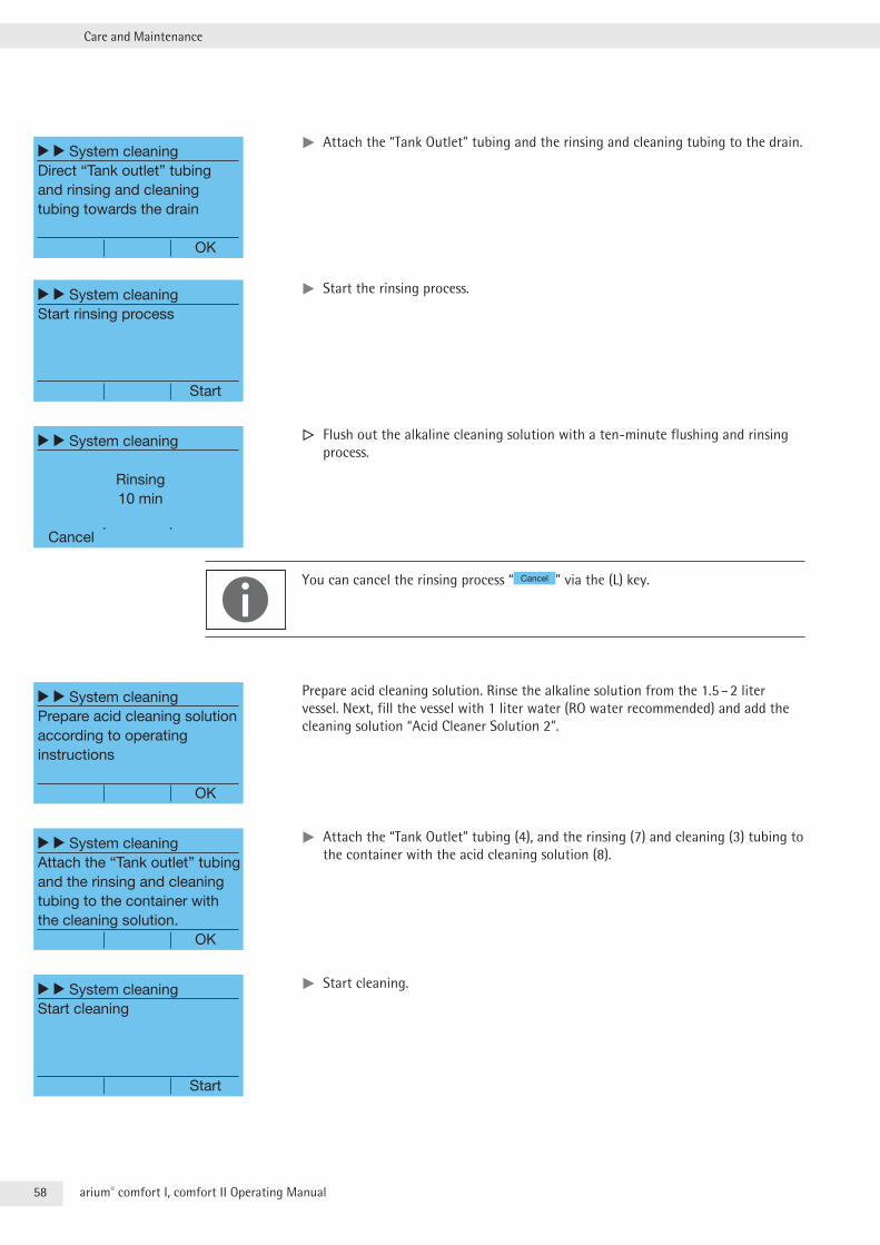
58 arium® comfort I, comfort II Operating Manual
Care and Maintenance
tt Attach the “Tank Outlet” tubing and the rinsing and cleaning tubing to the drain .
tt Start the rinsing process .
y Flush out the alkaline cleaning solution with a ten-minute flushing and rinsing process .
You can cancel the rinsing process “ Cancel ” via the (L) key .
Prepare acid cleaning solution . Rinse the alkaline solution from the 1 .5 – 2 liter vessel . Next, fill the vessel with 1 liter water (RO water recommended) and add the cleaning solution “Acid Cleaner Solution 2” .
tt Attach the “Tank Outlet” tubing (4), and the rinsing (7) and cleaning (3) tubing to the container with the acid cleaning solution (8) .
tt Start cleaning .
r r System cleaningDirect “Tank outlet” tubing and rinsing and cleaning tubing towards the drain
OK
r r System cleaningStart rinsing process
Start
r r System cleaning
Rinsing10 min
Cancel
r r System cleaningPrepare acid cleaning solution according to operatinginstructions
OK
r r System cleaningAttach the “Tank outlet” tubing and the rinsing and cleaning tubing to the container with the cleaning solution. OK
r r System cleaningStart cleaning
Start
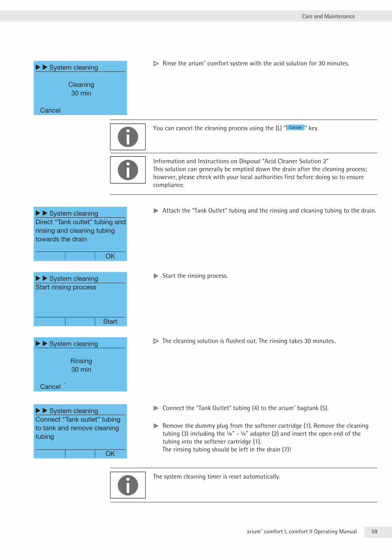
59arium® comfort I, comfort II Operating Manual
Care and Maintenance
y Rinse the arium® comfort system with the acid solution for 30 minutes .
You can cancel the cleaning process using the (L) “ Cancel ” key .
Information and Instructions on Disposal “Acid Cleaner Solution 2” This solution can generally be emptied down the drain after the cleaning process; however, please check with your local authorities first before doing so to ensure compliance .
tt Attach the “Tank Outlet” tubing and the rinsing and cleaning tubing to the drain .
tt Start the rinsing process .
y The cleaning solution is flushed out . The rinsing takes 30 minutes . .
tt Connect the “Tank Outlet“ tubing (4) to the arium® bagtank (5) .
tt Remove the dummy plug from the softener cartridge (1) . Remove the cleaning tubing (3) including the ¼” - ¼” adapter (2) and insert the open end of the tubing into the softener cartridge (1) . The rinsing tubing should be left in the drain (7)!
The system cleaning timer is reset automatically .
r r System cleaning
Cleaning30 min
Cancel
r r System cleaningDirect “Tank outlet” tubing and rinsing and cleaning tubing towards the drain
OK
r r System cleaningStart rinsing process
Start
r r System cleaning
Rinsing30 min
Cancel
r r System cleaningConnect “Tank outlet” tubing to tank and remove cleaning tubing
OK
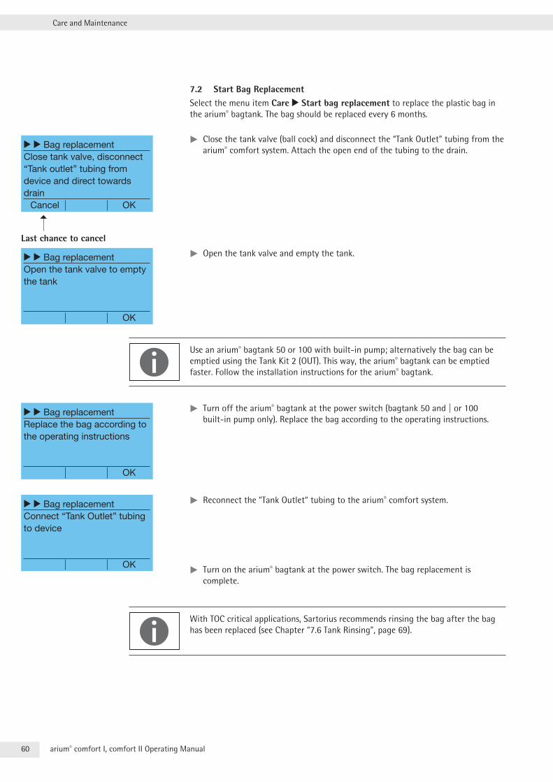
60 arium® comfort I, comfort II Operating Manual
Care and Maintenance
7.2 Start Bag ReplacementSelect the menu item Care r Start bag replacement to replace the plastic bag in the arium® bagtank . The bag should be replaced every 6 months .
tt Close the tank valve (ball cock) and disconnect the “Tank Outlet” tubing from the arium® comfort system . Attach the open end of the tubing to the drain .
tt Open the tank valve and empty the tank .
Use an arium® bagtank 50 or 100 with built-in pump; alternatively the bag can be emptied using the Tank Kit 2 (OUT) . This way, the arium® bagtank can be emptied faster . Follow the installation instructions for the arium® bagtank .
tt Turn off the arium® bagtank at the power switch (bagtank 50 and | or 100 built-in pump only) . Replace the bag according to the operating instructions .
tt Reconnect the “Tank Outlet“ tubing to the arium® comfort system .
tt Turn on the arium® bagtank at the power switch . The bag replacement is complete .
With TOC critical applications, Sartorius recommends rinsing the bag after the bag has been replaced (see Chapter “7 .6 Tank Rinsing”, page 69) .
r r Bag replacementClose tank valve, disconnect “Tank outlet” tubing from device and direct towards drain Cancel OK
Last chance to cancel
r r Bag replacementOpen the tank valve to empty the tank
OK
r r Bag replacementReplace the bag according to the operating instructions
OK
r r Bag replacementConnect “Tank Outlet” tubing to device
OK
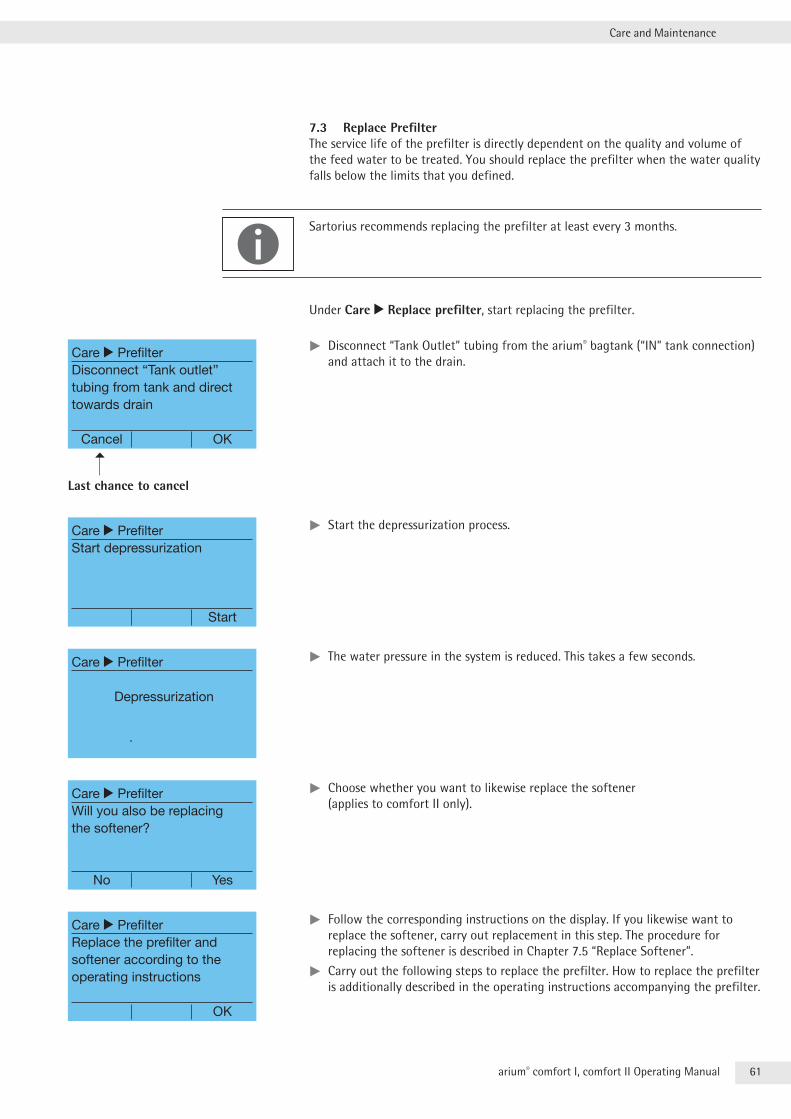
61arium® comfort I, comfort II Operating Manual
Care and Maintenance
7.3 Replace PrefilterThe service life of the prefilter is directly dependent on the quality and volume of the feed water to be treated . You should replace the prefilter when the water quality falls below the limits that you defined .
Sartorius recommends replacing the prefilter at least every 3 months .
Under Care r Replace prefilter, start replacing the prefilter .
tt Disconnect “Tank Outlet” tubing from the arium® bagtank (“IN” tank connection) and attach it to the drain .
tt Start the depressurization process .
tt The water pressure in the system is reduced . This takes a few seconds .
tt Choose whether you want to likewise replace the softener (applies to comfort II only) .
tt Follow the corresponding instructions on the display . If you likewise want to replace the softener, carry out replacement in this step . The procedure for replacing the softener is described in Chapter 7 .5 “Replace Softener” .
tt Carry out the following steps to replace the prefilter . How to replace the prefilter is additionally described in the operating instructions accompanying the prefilter .
Care r PrefilterDisconnect “Tank outlet” tubing from tank and direct towards drain
Cancel OK
Last chance to cancel
Care r PrefilterStart depressurization
Start
Care r Prefilter
Depressurization
Care r PrefilterWill you also be replacing the softener?
No Yes
Care r PrefilterReplace the prefilter and softener according to the operating instructions
OK
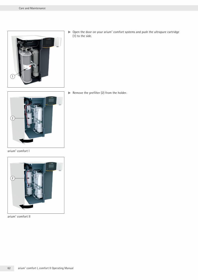
62 arium® comfort I, comfort II Operating Manual
Care and Maintenance
tt Open the door on your arium® comfort systems and push the ultrapure cartridge (1) to the side .
tt Remove the prefilter (2) from the holder .
1
2
arium® comfort I
2
arium® comfort II

63arium® comfort I, comfort II Operating Manual
Care and Maintenance
tt Remove the old prefilter by unscrewing the upper gray (3) and lower red (4) tubing connections .
tt Remove the new prefilter from the packaging and write the date of installation under “Date of installation” on the label .
tt Connect the new prefilter . Connect the upper gray (3) and the lower red (4) tubing connectors .
tt Press the new prefilter into the holder (2) .
tt Insert the ultrapure water cartridge (1) back in the device and close the device door .
tt Start the rinsing process .
y The new prefilter and | or the softener are rinsed for 30 minutes .
tt Connect the “Tank Outlet” tubing to the arium® bagtank .
Replacing the prefilter and | or the softener is complete . The system switches back to operating mode .
The prefilter timer is reset automatically .
4
3
Care PrefilterStart rinsing process
Start
Care r Prefilter
Rinsing30 min
Cancel
Care PrefilterConnect “Tank outlet” tubing to tank
OK
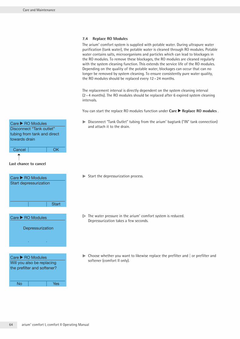
64 arium® comfort I, comfort II Operating Manual
Care and Maintenance
7.4 Replace RO ModulesThe arium® comfort system is supplied with potable water . During ultrapure water purification (tank water), the potable water is cleaned through RO modules . Potable water contains salts, microorganisms and particles which can lead to blockages in the RO modules . To remove these blockages, the RO modules are cleaned regularly with the system cleaning function . This extends the service life of the RO modules . Depending on the quality of the potable water, blockages can occur that can no longer be removed by system cleaning . To ensure consistently pure water quality, the RO modules should be replaced every 12 – 24 months .
The replacement interval is directly dependent on the system cleaning interval (2 – 4 months) . The RO modules should be replaced after 6 expired system cleaning intervals .
You can start the replace RO modules function under Care r Replace RO modules .
tt Disconnect “Tank Outlet” tubing from the arium® bagtank (“IN” tank connection) and attach it to the drain .
tt Start the depressurization process .
y The water pressure in the arium® comfort system is reduced . Depressurization takes a few seconds .
tt Choose whether you want to likewise replace the prefilter and | or prefilter and softener (comfort II only) .
Care r RO ModulesDisconnect “Tank outlet” tubing from tank and direct towards drain
Cancel OK
Last chance to cancel
Care r RO ModulesStart depressurization
Start
Care r RO Modules
Depressurization
Care r RO ModulesWill you also be replacing the prefilter and softener?
No Yes
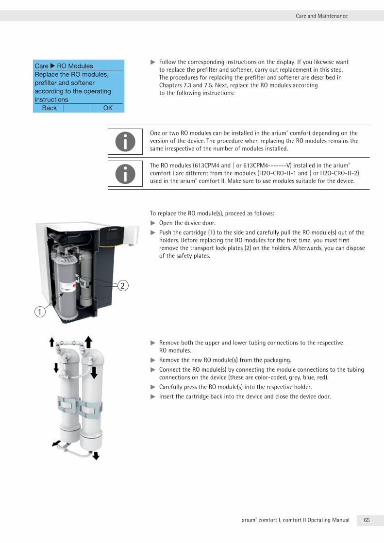
65arium® comfort I, comfort II Operating Manual
Care and Maintenance
tt Follow the corresponding instructions on the display . If you likewise want to replace the prefilter and softener, carry out replacement in this step . The procedures for replacing the prefilter and softener are described in Chapters 7 .3 and 7 .5 . Next, replace the RO modules according to the following instructions:
One or two RO modules can be installed in the arium® comfort depending on the version of the device . The procedure when replacing the RO modules remains the same irrespective of the number of modules installed .
The RO modules (613CPM4 and | or 613CPM4-------V) installed in the arium® comfort I are different from the modules (H2O-CRO-H-1 and | or H2O-CRO-H-2) used in the arium® comfort II . Make sure to use modules suitable for the device .
To replace the RO module(s), proceed as follows:
tt Open the device door .
tt Push the cartridge (1) to the side and carefully pull the RO module(s) out of the holders . Before replacing the RO modules for the first time, you must first remove the transport lock plates (2) on the holders . Afterwards, you can dispose of the safety plates .
tt Remove both the upper and lower tubing connections to the respective RO modules .
tt Remove the new RO module(s) from the packaging .
tt Connect the RO module(s) by connecting the module connections to the tubing connections on the device (these are color-coded, grey, blue, red) .
tt Carefully press the RO module(s) into the respective holder .
tt Insert the cartridge back into the device and close the device door .
Care r RO ModulesReplace the RO modules, prefilter and softener according to the operating instructions Back OK
1
2
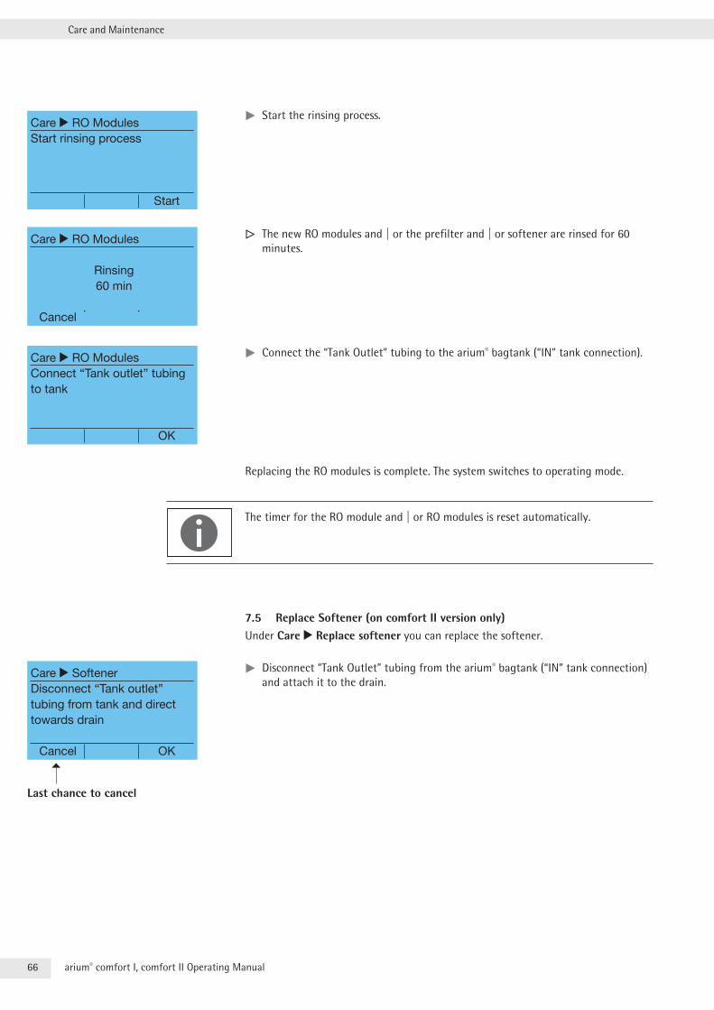
66 arium® comfort I, comfort II Operating Manual
Care and Maintenance
tt Start the rinsing process .
y The new RO modules and | or the prefilter and | or softener are rinsed for 60 minutes .
tt Connect the “Tank Outlet” tubing to the arium® bagtank (“IN” tank connection) .
Replacing the RO modules is complete . The system switches to operating mode .
The timer for the RO module and | or RO modules is reset automatically .
7.5 Replace Softener (on comfort II version only)Under Care r Replace softener you can replace the softener .
tt Disconnect “Tank Outlet” tubing from the arium® bagtank (“IN” tank connection) and attach it to the drain .
Care r RO ModulesStart rinsing process
Start
Care r RO Modules
Rinsing60 min
Cancel
Care r RO ModulesConnect “Tank outlet” tubing to tank
OK
Care r SoftenerDisconnect “Tank outlet” tubing from tank and direct towards drain
Cancel OK
Last chance to cancel
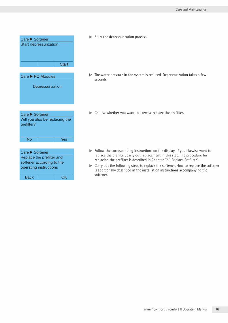
67arium® comfort I, comfort II Operating Manual
Care and Maintenance
tt Start the depressurization process .
y The water pressure in the system is reduced . Depressurization takes a few seconds .
tt Choose whether you want to likewise replace the prefilter .
tt Follow the corresponding instructions on the display . If you likewise want to replace the prefilter, carry out replacement in this step . The procedure for replacing the prefilter is described in Chapter “7 .3 Replace Prefilter” .
tt Carry out the following steps to replace the softener . How to replace the softener is additionally described in the installation instructions accompanying the softener .
Care r SoftenerStart depressurization
Start
Care r RO Modules
Depressurization
Care r SoftenerWill you also be replacing the prefilter?
No Yes
Care r SoftenerReplace the prefilter and softener according to the operating instructions
Back OK
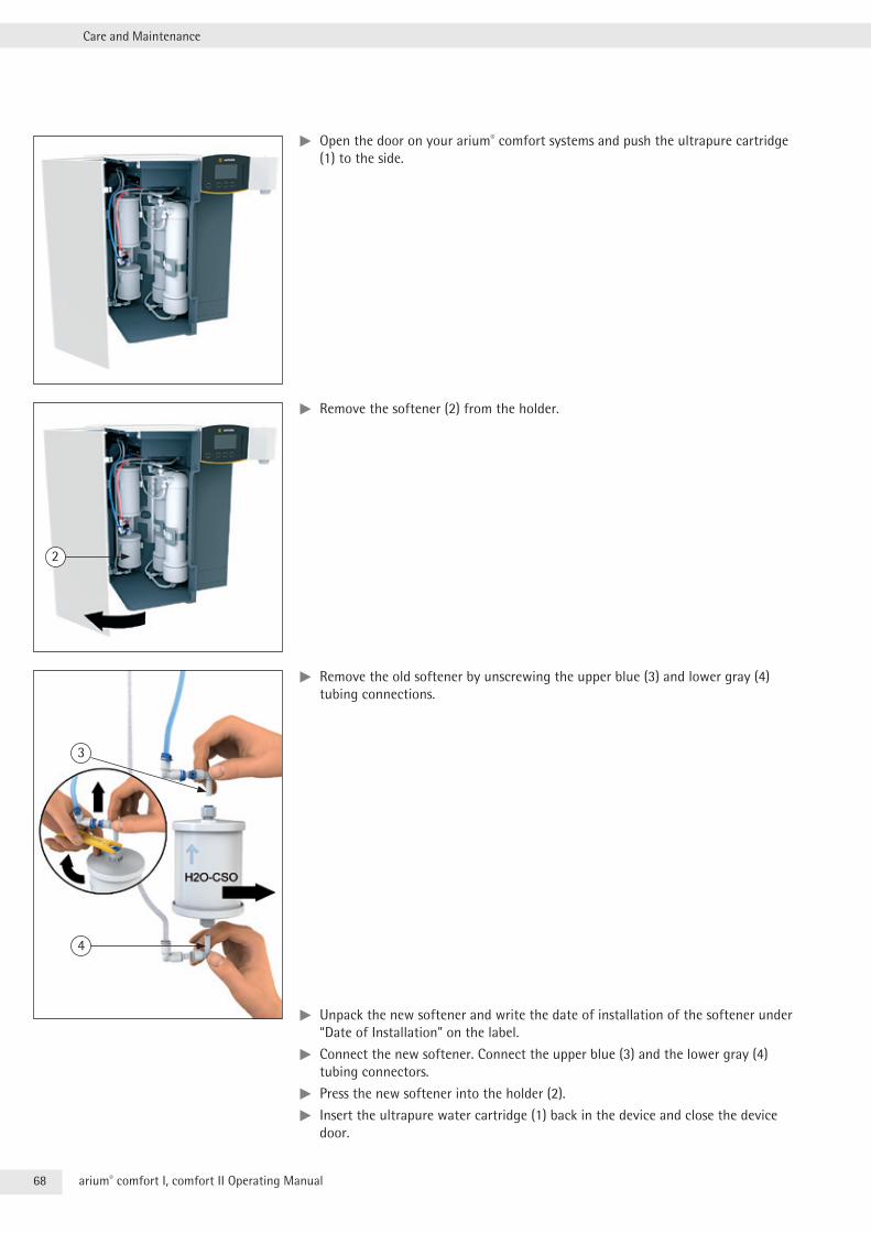
68 arium® comfort I, comfort II Operating Manual
Care and Maintenance
tt Open the door on your arium® comfort systems and push the ultrapure cartridge (1) to the side .
tt Remove the softener (2) from the holder .
tt Remove the old softener by unscrewing the upper blue (3) and lower gray (4) tubing connections .
tt Unpack the new softener and write the date of installation of the softener under “Date of Installation” on the label .
tt Connect the new softener . Connect the upper blue (3) and the lower gray (4) tubing connectors .
tt Press the new softener into the holder (2) .
tt Insert the ultrapure water cartridge (1) back in the device and close the device door .
2
3
4
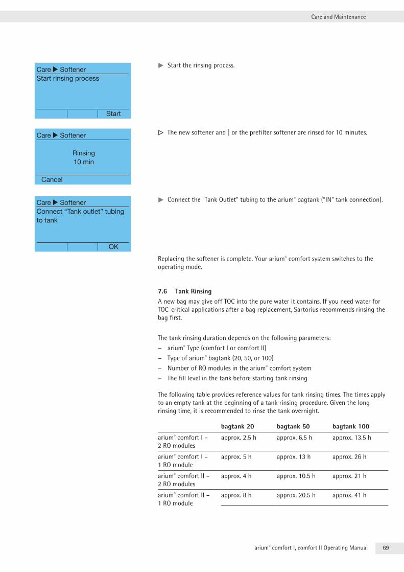
69arium® comfort I, comfort II Operating Manual
Care and Maintenance
tt Start the rinsing process .
y The new softener and | or the prefilter softener are rinsed for 10 minutes .
tt Connect the “Tank Outlet” tubing to the arium® bagtank (“IN” tank connection) .
Replacing the softener is complete . Your arium® comfort system switches to the operating mode .
7.6 Tank RinsingA new bag may give off TOC into the pure water it contains . If you need water for TOC-critical applications after a bag replacement, Sartorius recommends rinsing the bag first .
The tank rinsing duration depends on the following parameters:
− arium® Type (comfort I or comfort II)
− Type of arium® bagtank (20, 50, or 100)
− Number of RO modules in the arium® comfort system
− The fill level in the tank before starting tank rinsing
The following table provides reference values for tank rinsing times . The times apply to an empty tank at the beginning of a tank rinsing procedure . Given the long rinsing time, it is recommended to rinse the tank overnight .
bagtank 20 bagtank 50 bagtank 100
arium® comfort I – 2 RO modules
approx . 2 .5 h approx . 6 .5 h approx . 13 .5 h
arium® comfort I – 1 RO module
approx . 5 h approx . 13 h approx . 26 h
arium® comfort II – 2 RO modules
approx . 4 h approx . 10 .5 h approx . 21 h
arium® comfort II – 1 RO module
approx . 8 h approx . 20 .5 h approx . 41 h
Care r SoftenerStart rinsing process
Start
Care r Softener
Rinsing10 min
Cancel
Care r SoftenerConnect “Tank outlet” tubing to tank
OK
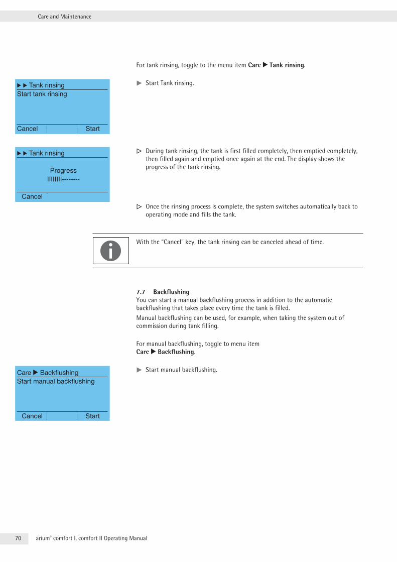
70 arium® comfort I, comfort II Operating Manual
Care and Maintenance
For tank rinsing, toggle to the menu item Care r Tank rinsing .
tt Start Tank rinsing .
y During tank rinsing, the tank is first filled completely, then emptied completely, then filled again and emptied once again at the end . The display shows the progress of the tank rinsing .
y Once the rinsing process is complete, the system switches automatically back to operating mode and fills the tank .
With the “Cancel” key, the tank rinsing can be canceled ahead of time .
7.7 BackflushingYou can start a manual backflushing process in addition to the automatic backflushing that takes place every time the tank is filled .
Manual backflushing can be used, for example, when taking the system out of commission during tank filling .
For manual backflushing, toggle to menu item Care r Backflushing .
tt Start manual backflushing .
r r Tank rinsingStart tank rinsing
Cancel Start
r r Tank rinsing
ProgressIIIIIIII--------
Cancel
Care r BackflushingStart manual backflushing
Cancel Start
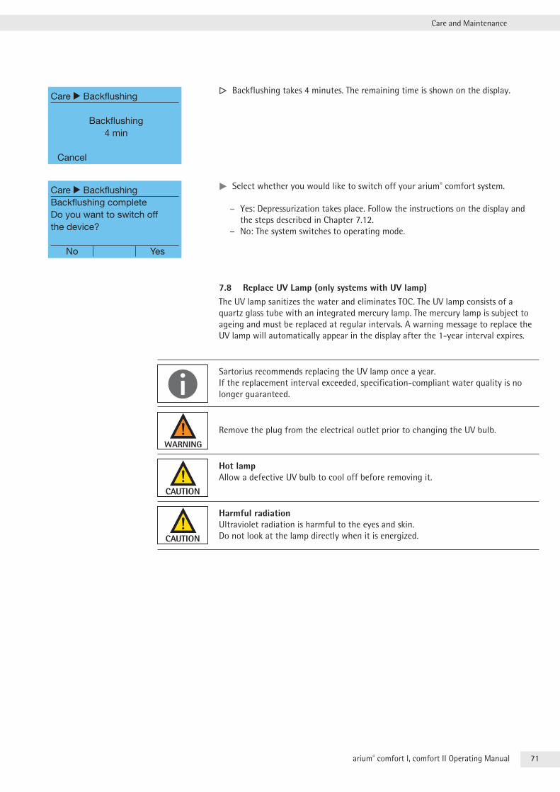
71arium® comfort I, comfort II Operating Manual
Care and Maintenance
y Backflushing takes 4 minutes . The remaining time is shown on the display .
tt Select whether you would like to switch off your arium® comfort system .
− Yes: Depressurization takes place . Follow the instructions on the display and the steps described in Chapter 7 .12 .
− No: The system switches to operating mode .
7.8 Replace UV Lamp (only systems with UV lamp)The UV lamp sanitizes the water and eliminates TOC . The UV lamp consists of a quartz glass tube with an integrated mercury lamp . The mercury lamp is subject to ageing and must be replaced at regular intervals . A warning message to replace the UV lamp will automatically appear in the display after the 1-year interval expires .
Sartorius recommends replacing the UV lamp once a year . If the replacement interval exceeded, specification-compliant water quality is no longer guaranteed .
Remove the plug from the electrical outlet prior to changing the UV bulb .
Hot lamp Allow a defective UV bulb to cool off before removing it .
Harmful radiation Ultraviolet radiation is harmful to the eyes and skin . Do not look at the lamp directly when it is energized .
Care r Backflushing
Backflushing4 min
Cancel
Care r BackflushingBackflushing completeDo you want to switch off the device?
No Yes
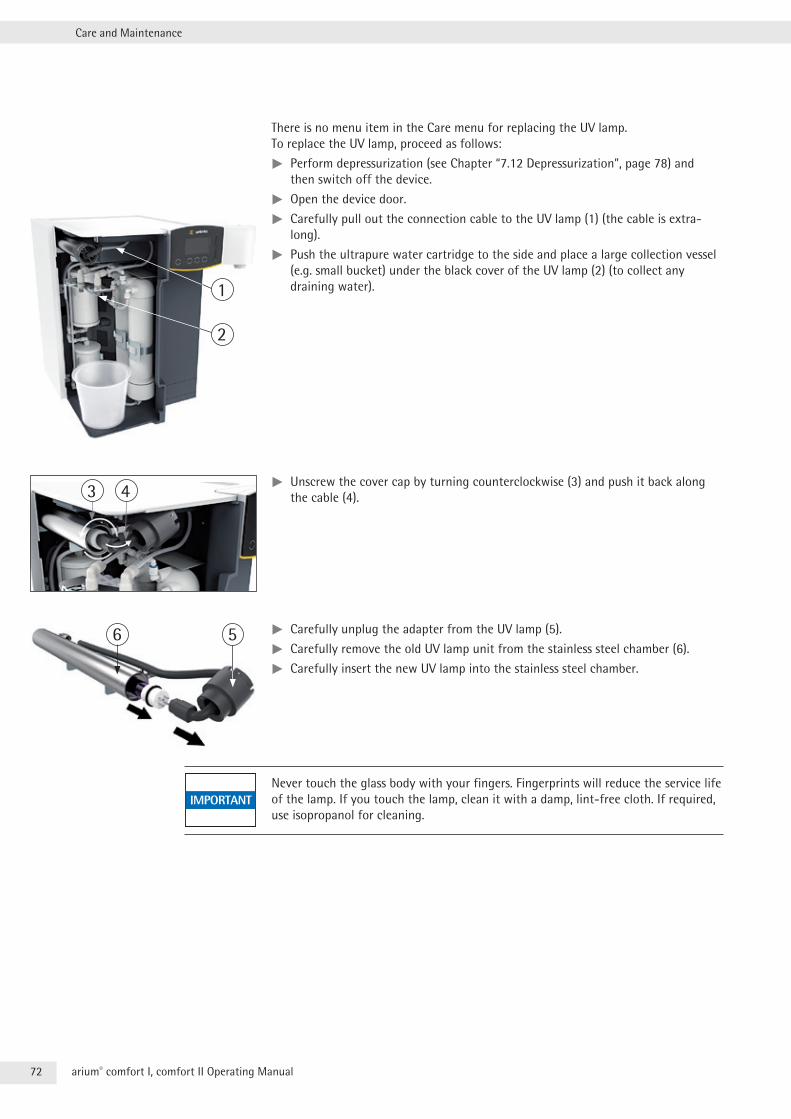
72 arium® comfort I, comfort II Operating Manual
Care and Maintenance
There is no menu item in the Care menu for replacing the UV lamp . To replace the UV lamp, proceed as follows:
tt Perform depressurization (see Chapter “7 .12 Depressurization”, page 78) and then switch off the device .
tt Open the device door .
tt Carefully pull out the connection cable to the UV lamp (1) (the cable is extra-long) .
tt Push the ultrapure water cartridge to the side and place a large collection vessel (e .g . small bucket) under the black cover of the UV lamp (2) (to collect any draining water) .
tt Unscrew the cover cap by turning counterclockwise (3) and push it back along the cable (4) .
tt Carefully unplug the adapter from the UV lamp (5) .
tt Carefully remove the old UV lamp unit from the stainless steel chamber (6) .
tt Carefully insert the new UV lamp into the stainless steel chamber .
Never touch the glass body with your fingers . Fingerprints will reduce the service life of the lamp . If you touch the lamp, clean it with a damp, lint-free cloth . If required, use isopropanol for cleaning .
1
2
3 4
56
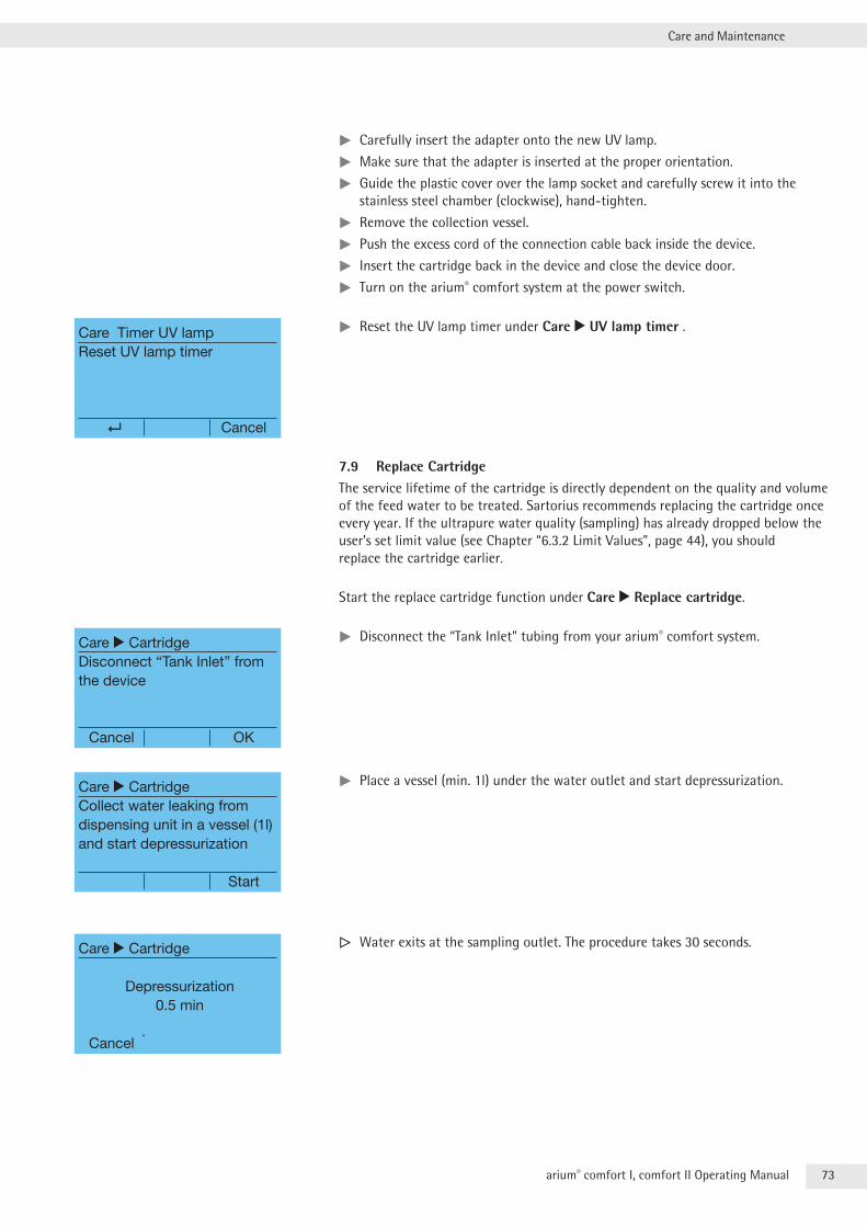
73arium® comfort I, comfort II Operating Manual
Care and Maintenance
tt Carefully insert the adapter onto the new UV lamp .
tt Make sure that the adapter is inserted at the proper orientation .
tt Guide the plastic cover over the lamp socket and carefully screw it into the stainless steel chamber (clockwise), hand-tighten .
tt Remove the collection vessel .
tt Push the excess cord of the connection cable back inside the device .
tt Insert the cartridge back in the device and close the device door .
tt Turn on the arium® comfort system at the power switch .
tt Reset the UV lamp timer under Care r UV lamp timer .
7.9 Replace CartridgeThe service lifetime of the cartridge is directly dependent on the quality and volume of the feed water to be treated . Sartorius recommends replacing the cartridge once every year . If the ultrapure water quality (sampling) has already dropped below the user’s set limit value (see Chapter “6 .3 .2 Limit Values”, page 44), you should replace the cartridge earlier .
Start the replace cartridge function under Care r Replace cartridge .
tt Disconnect the “Tank Inlet” tubing from your arium® comfort system .
tt Place a vessel (min . 1l) under the water outlet and start depressurization .
y Water exits at the sampling outlet . The procedure takes 30 seconds .
Care Timer UV lampReset UV lamp timer
Cancel
Care r CartridgeDisconnect “Tank Inlet” from the device
Cancel OK
Care r CartridgeCollect water leaking from dispensing unit in a vessel (1l) and start depressurization
Start
Care r Cartridge
Depressurization0.5 min
Cancel
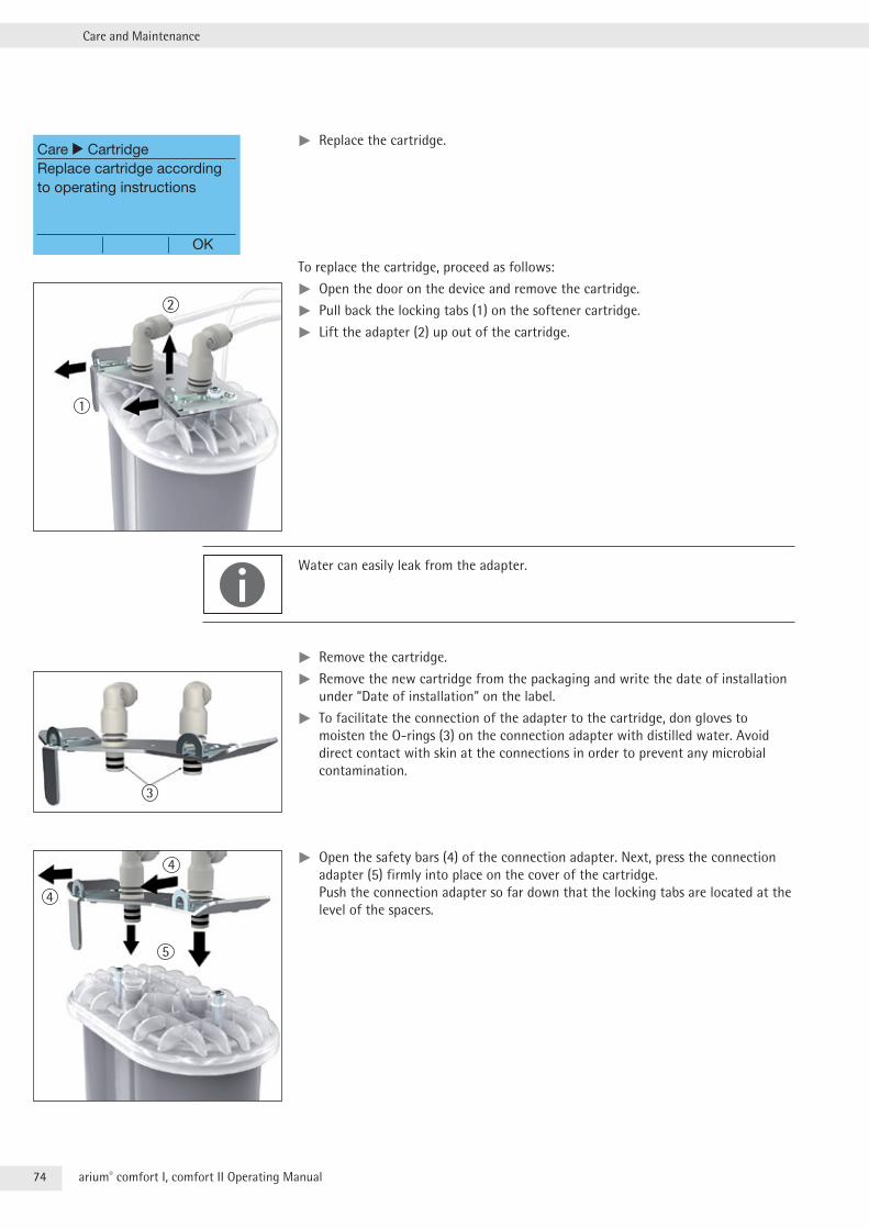
74 arium® comfort I, comfort II Operating Manual
Care and Maintenance
tt Replace the cartridge .
To replace the cartridge, proceed as follows:
tt Open the door on the device and remove the cartridge .
tt Pull back the locking tabs (1) on the softener cartridge .
tt Lift the adapter (2) up out of the cartridge .
Water can easily leak from the adapter .
tt Remove the cartridge .
tt Remove the new cartridge from the packaging and write the date of installation under “Date of installation” on the label .
tt To facilitate the connection of the adapter to the cartridge, don gloves to moisten the O-rings (3) on the connection adapter with distilled water . Avoid direct contact with skin at the connections in order to prevent any microbial contamination .
tt Open the safety bars (4) of the connection adapter . Next, press the connection adapter (5) firmly into place on the cover of the cartridge . Push the connection adapter so far down that the locking tabs are located at the level of the spacers .
Care r CartridgeReplace cartridge according to operating instructions
OK
2
1
3
4
5
4
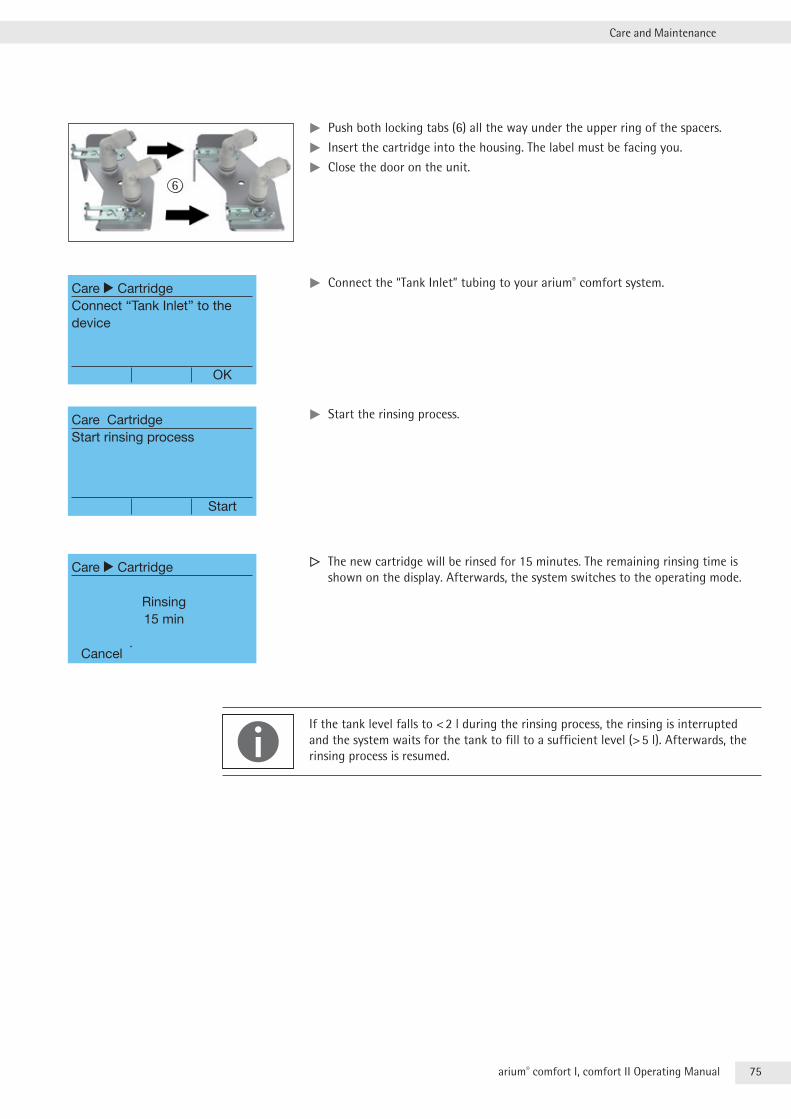
75arium® comfort I, comfort II Operating Manual
Care and Maintenance
tt Push both locking tabs (6) all the way under the upper ring of the spacers .
tt Insert the cartridge into the housing . The label must be facing you .
tt Close the door on the unit .
tt Connect the “Tank Inlet” tubing to your arium® comfort system .
tt Start the rinsing process .
y The new cartridge will be rinsed for 15 minutes . The remaining rinsing time is shown on the display . Afterwards, the system switches to the operating mode .
If the tank level falls to < 2 l during the rinsing process, the rinsing is interrupted and the system waits for the tank to fill to a sufficient level (> 5 l) . Afterwards, the rinsing process is resumed .
6
Care r CartridgeConnect “Tank Inlet” to the device
OK
Care CartridgeStart rinsing process
Start
Care r Cartridge
Rinsing15 min
Cancel
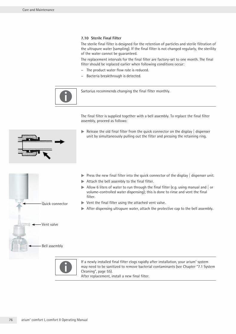
76 arium® comfort I, comfort II Operating Manual
Care and Maintenance
7.10 Sterile Final FilterThe sterile final filter is designed for the retention of particles and sterile filtration of the ultrapure water (sampling) . If the final filter is not changed regularly, the sterility of the water cannot be guaranteed .
The replacement intervals for the final filter are factory-set to one month . The final filter should be replaced earlier when following conditions occur:
− The product water flow rate is reduced .
− Bacteria breakthrough is detected .
Sartorius recommends changing the final filter monthly .
The final filter is supplied together with a bell assembly . To replace the final filter assembly, proceed as follows:
tt Release the old final filter from the quick connector on the display | dispenser unit by simultaneously pulling out the filter and pressing the retaining ring .
tt Press the new final filter into the quick connector of the display | dispenser unit .
tt Attach the bell assembly to the final filter .
tt Allow 6 liters of water to run through the final filter (e .g . using manual and | or volume-controlled water dispensing); this is done to rinse and vent the final filter .
tt Vent the final filter using the attached vent valve .
tt After dispensing ultrapure water, attach the protective cap to the bell assembly .
If a newly installed final filter clogs rapidly after installation, your arium® system may need to be sanitized to remove bacterial contaminants (see Chapter “7 .1 System Cleaning”, page 55) . After replacement, install a new final filter .
Quick connector
Vent valve
Bell assembly
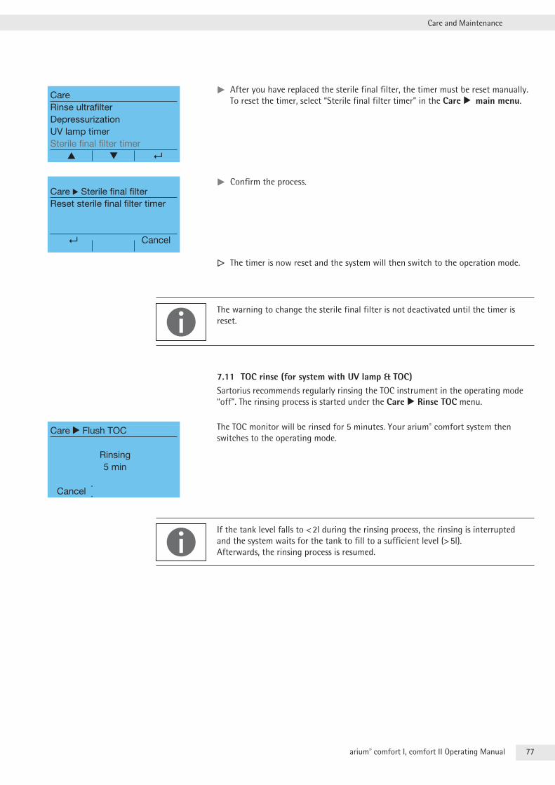
77arium® comfort I, comfort II Operating Manual
Care and Maintenance
tt After you have replaced the sterile final filter, the timer must be reset manually . To reset the timer, select “Sterile final filter timer” in the Care r main menu .
tt Confirm the process .
y The timer is now reset and the system will then switch to the operation mode .
The warning to change the sterile final filter is not deactivated until the timer is reset .
7.11 TOC rinse (for system with UV lamp & TOC)Sartorius recommends regularly rinsing the TOC instrument in the operating mode “off” . The rinsing process is started under the Care r Rinse TOC menu .
The TOC monitor will be rinsed for 5 minutes . Your arium® comfort system then switches to the operating mode .
If the tank level falls to < 2l during the rinsing process, the rinsing is interrupted and the system waits for the tank to fill to a sufficient level (> 5l) . Afterwards, the rinsing process is resumed .
CareRinse ultrafilterDepressurizationUV lamp timerSterile final filter timer ▲ ▼
Care r Sterile final filterReset sterile final filter timer
Cancel
Care r Flush TOC
Rinsing5 min
Cancel
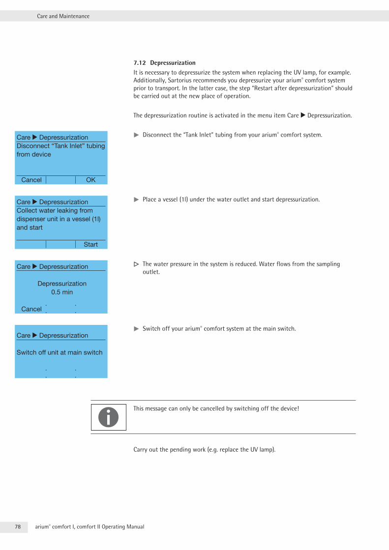
78 arium® comfort I, comfort II Operating Manual
Care and Maintenance
7.12 DepressurizationIt is necessary to depressurize the system when replacing the UV lamp, for example . Additionally, Sartorius recommends you depressurize your arium® comfort system prior to transport . In the latter case, the step “Restart after depressurization” should be carried out at the new place of operation .
The depressurization routine is activated in the menu item Care r Depressurization .
tt Disconnect the “Tank Inlet” tubing from your arium® comfort system .
tt Place a vessel (1l) under the water outlet and start depressurization .
y The water pressure in the system is reduced . Water flows from the sampling outlet .
tt Switch off your arium® comfort system at the main switch .
This message can only be cancelled by switching off the device!
Carry out the pending work (e .g . replace the UV lamp) .
Care r DepressurizationDisconnect “Tank Inlet” tubing from device
Cancel OK
Care r DepressurizationCollect water leaking from dispenser unit in a vessel (1l) and start
Start
Care r Depressurization
Depressurization0.5 min
Cancel
Care r Depressurization
Switch off unit at main switch
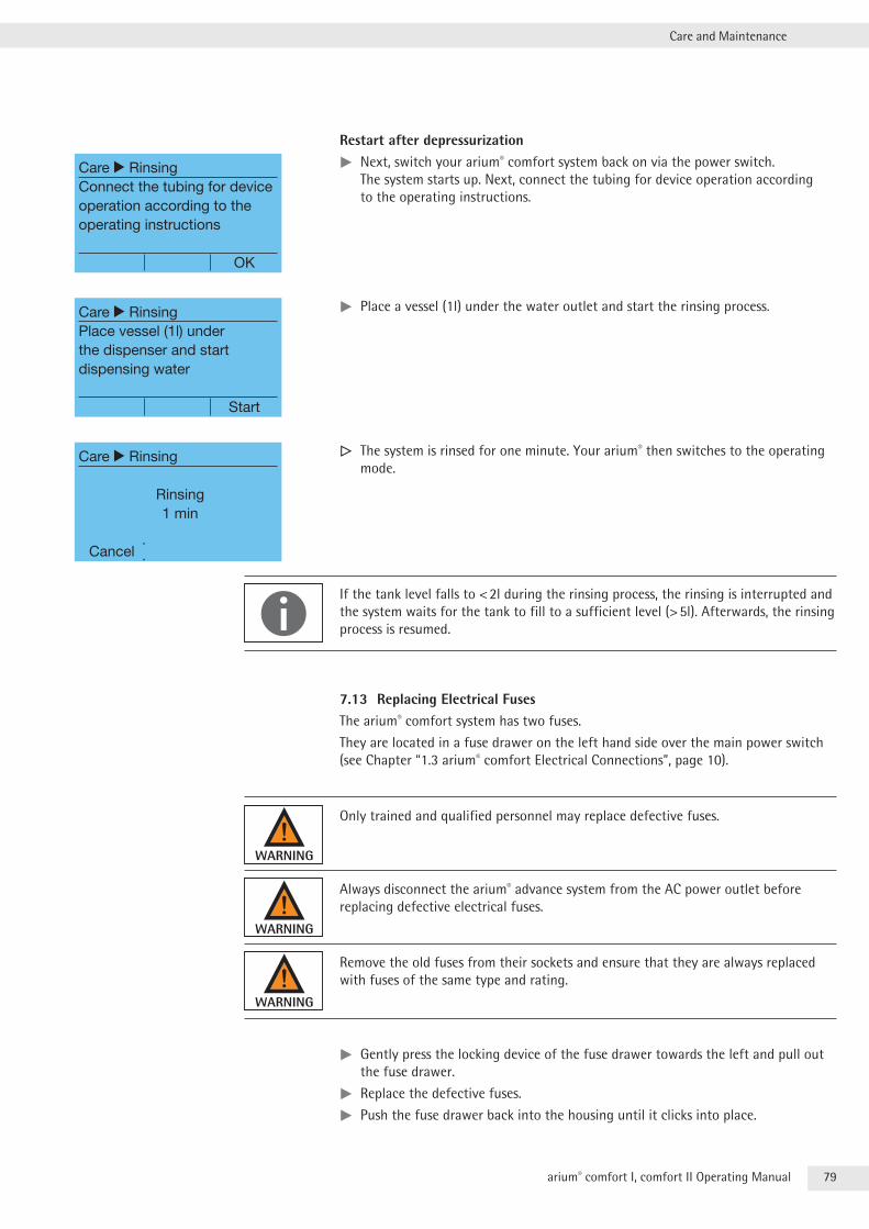
79arium® comfort I, comfort II Operating Manual
Care and Maintenance
Restart after depressurizationtt Next, switch your arium® comfort system back on via the power switch . The system starts up . Next, connect the tubing for device operation according to the operating instructions .
tt Place a vessel (1l) under the water outlet and start the rinsing process .
y The system is rinsed for one minute . Your arium® then switches to the operating mode .
If the tank level falls to < 2l during the rinsing process, the rinsing is interrupted and the system waits for the tank to fill to a sufficient level (> 5l) . Afterwards, the rinsing process is resumed .
7.13 Replacing Electrical FusesThe arium® comfort system has two fuses .
They are located in a fuse drawer on the left hand side over the main power switch (see Chapter “1 .3 arium® comfort Electrical Connections”, page 10) .
Only trained and qualified personnel may replace defective fuses .
Always disconnect the arium® advance system from the AC power outlet before replacing defective electrical fuses .
Remove the old fuses from their sockets and ensure that they are always replaced with fuses of the same type and rating .
tt Gently press the locking device of the fuse drawer towards the left and pull out the fuse drawer .
tt Replace the defective fuses .
tt Push the fuse drawer back into the housing until it clicks into place .
Care r RinsingConnect the tubing for device operation according to the operating instructions
OK
Care r RinsingPlace vessel (1l) under the dispenser and start dispensing water
Start
Care r Rinsing
Rinsing1 min
Cancel
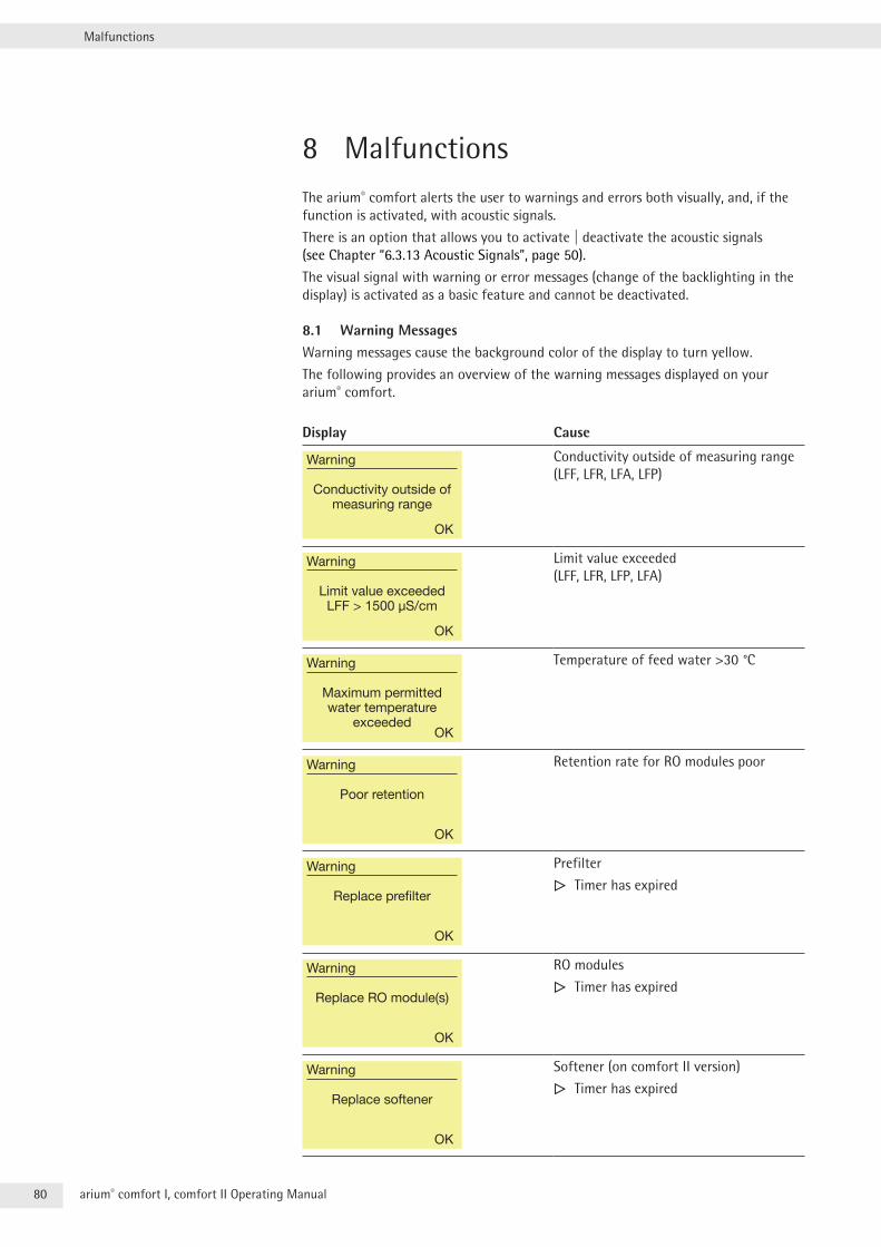
80 arium® comfort I, comfort II Operating Manual
Malfunctions
8 MalfunctionsThe arium® comfort alerts the user to warnings and errors both visually, and, if the function is activated, with acoustic signals .
There is an option that allows you to activate | deactivate the acoustic signals (see Chapter “6 .3 .13 Acoustic Signals”, page 50) .
The visual signal with warning or error messages (change of the backlighting in the display) is activated as a basic feature and cannot be deactivated .
8.1 Warning MessagesWarning messages cause the background color of the display to turn yellow .
The following provides an overview of the warning messages displayed on your arium® comfort .
Display Cause
Warning
Conductivity outside of measuring range
OK
Conductivity outside of measuring range (LFF, LFR, LFA, LFP)
Warning
Limit value exceededLFF > 1500 µS/cm
OK
Limit value exceeded (LFF, LFR, LFP, LFA)
Warning
Maximum permitted water temperature
exceededOK
Temperature of feed water >30 °C
Warning
Poor retention
OK
Retention rate for RO modules poor
Warning
Replace prefilter
OK
Prefilter
y Timer has expired
Warning
Replace RO module(s)
OK
RO modules
y Timer has expired
Warning
Replace softener
OK
Softener (on comfort II version)
y Timer has expired
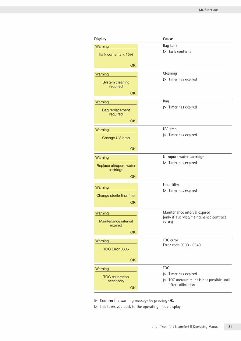
81arium® comfort I, comfort II Operating Manual
Malfunctions
Display Cause
Warning
Tank contents < 15%
OK
Bag tank
y Tank contents
Warning
System cleaning required
OK
Cleaning
y Timer has expired
Warning
Bag replacement required
OK
Bag
y Timer has expired
Warning
Change UV lamp
OK
UV lamp
y Timer has expired
Warning
Replace ultrapure water cartridge
OK
Ultrapure water cartridge
y Timer has expired
Warning
Change sterile final filter
OK
Final filter
y Timer has expired
Warning
Maintenance interval expired
OK
Maintenance interval expired(only if a service/maintenance contract exists)
Warning
TOC Error 0305
OK
TOC errorError code 0300 - 0340
Warning
TOC calibration necessary
OK
TOC
y Timer has expired
y TOC measurement is not possible until after calibration
tt Confirm the warning message by pressing OK .
y This takes you back to the operating mode display .
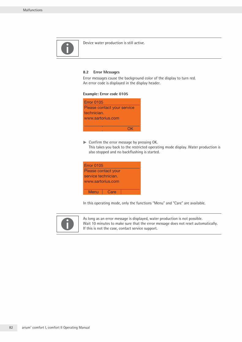
82 arium® comfort I, comfort II Operating Manual
Malfunctions
Device water production is still active .
8.2 Error MessagesError messages cause the background color of the display to turn red . An error code is displayed in the display header .
Example: Error code 0105
Error 0105Please contact your service technician.www.sartorius.com
OK
tt Confirm the error message by pressing OK . This takes you back to the restricted operating mode display . Water production is also stopped and no backflushing is started .
Error 0105Please contact your service technician.www.sartorius.com
Menu Care
In this operating mode, only the functions “Menu” and “Care” are available .
As long as an error message is displayed, water production is not possible . Wait 10 minutes to make sure that the error message does not reset automatically . If this is not the case, contact service support .
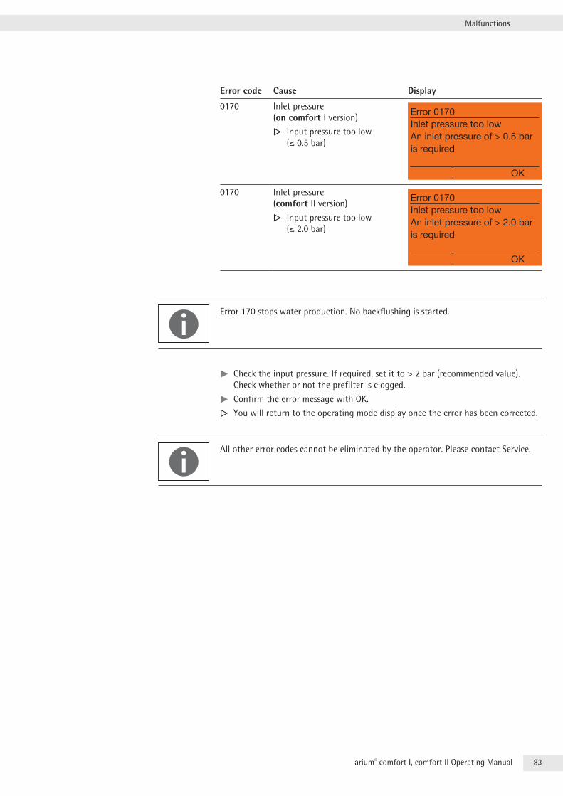
83arium® comfort I, comfort II Operating Manual
Malfunctions
Error code Cause Display
0170 Inlet pressure (on comfort I version)
y Input pressure too low (≤ 0 .5 bar)
Error 0170Inlet pressure too low An inlet pressure of > 0.5 bar is required
OK
0170 Inlet pressure (comfort II version)
y Input pressure too low (≤ 2 .0 bar)
Error 0170Inlet pressure too low An inlet pressure of > 2.0 bar is required
OK
Error 170 stops water production . No backflushing is started .
tt Check the input pressure . If required, set it to > 2 bar (recommended value) . Check whether or not the prefilter is clogged .
tt Confirm the error message with OK .
y You will return to the operating mode display once the error has been corrected .
All other error codes cannot be eliminated by the operator . Please contact Service .
84 arium® comfort I, comfort II Operating Manual
Disposal
9 Disposal9.1 Shipping InstructionsIf you return the arium® comfort system to Sartorius, you must use the original packaging .
We will be pleased to provide this on request .
9.2 Instructions for DisposalAttention must be paid to the applicable laws, rules and regulations when disposing of contaminated components .
If the packaging is no longer needed, it can be disposed of by local waste disposal authorities . The packaging is made of environmentally friendly materials that can be used as secondary raw materials .
The arium® comfort – including accessories – should not be disposed of as regular household waste . EU legislation requires its Member States to collect electrical and electronic equipment and dispose of it separately from other unsorted municipal waste so that it may be recycled .
In Germany and several other countries, Sartorius itself assumes responsibility for the return and conformant disposal of its electronic and electrical products . Such equipment may not be thrown out with household waste or brought to collection centers run by local public disposal operations – not even by small commercial operators .
For disposal in Germany and in the other member nations of the European Economic Area (EEA), please contact our local service technicians or our Service Center in Goettingen, Germany:
Sartorius Lab Instruments GmbH & Co . KG Service Center Weender Landstrasse 94 –108 37075 Goettingen
WEEE reg . no . DE 89907997
In countries that are not members of the European Economic Area (EEA) or where no Sartorius subsidiaries or dealerships are located, please contact your local authorities or a commercial disposal operator .
Prior to disposal and | or scrapping of the components, any batteries – if present – should be removed and disposed of in local collection boxes .
85arium® comfort I, comfort II Operating Manual
Disposal
Instructions for Disposal of UV LampsIn Germany, country-wide, environmentally-friendly disposal of end-of-life lamps is organized using the collection network Lightcycle . To find a collection site in your area, go to the HYPERLINK “http://www .lightcycle .de/index .php” Lightcycle .de Home
European UnionDisposal of waste electrical equipment and end-of-life lamps as domestic waste is prohibited . Our products are business-to-business products (B2B) in the sense of the WEEE Directive (Waste Electrical Electronic Equipment) .
Sartorius Weighing Technology GmbH has labeled all devices subject to the WEEE Directive with a crossed-out waste bin with a white bar underneath . This symbol indicates that disposal of the product as domestic waste is prohibited . Different European member countries have complied with the WEEE Directive by implement-ing their own national laws, which makes it impossible for Sartorius Weighing Technology GmbH to offer consistent disposal solutions throughout Europe .
The local distributor (importer) from each country is responsible for complying with these national laws . For proper disposal of waste equipment and end-of-life lamps in accordance with the respective national regulations in the European Union countries mentioned (except Germany), please contact your local dealer or our Service Center .
All Other CountriesFor disposal of waste equipment and end-of-life lamps in accordance with the respective national regulations in countries other than those mentioned above, please contact your local dealer our Service Center or the local authorities .
86 arium® comfort I, comfort II Operating Manual
Technical Specifications
10 Technical Specifications10.1 arium® comfort I (H2O-I-...)
Dimensions W + H + D: Without display unit With display unit350 mm + 492 mm + 451 mm 435 mm + 501 mm + 476 mm
Empty weight: approx . 23 kg
Operating weight: approx . 31 kg
Clearance requirements Sides Left: Right:
min . 150-230 mm min . 80 mm
Front 100 mm minimum for opening the doors
Power supply: 100 – 240 V AC (±10%), 50/60 Hz, 130 VA (max .) power input 2 fuses 5 + 20 mm, time lag, 250 V, 4 A/T
Connections: Serial interface RS232C
Character-coded
Plug connection 9-pin D-sub port
Transmission rate 9600 baud
Data bits 8
Parity odd (space for Sartorius data printer)
Stop bits 1
SD card Standard SD card, max . 4 GB, FAT formatted
Display port Alternative port for connecting the dispenser unit (on below-bench units)
Ethernet For servicing
Terminal block Connection for arium® bagtank and foot switch
Ambient operating conditions: Temperature 2 °C – 35 °C, at max . 80% relative humidity
Ambient storage conditions: Temperature 5 °C – 45 °C, at max . 80% relative humidity
Feed Water Requirements
Exclusively potable tap water (feed water must meet drinking water standards of the USA, European Union and Japan) . Conductivity: < 1500 µS/cm at 25 °C . Max . total hardness (max . CaCO3): 360 ppm
TOC: < 2000 ppb
Colloid index or SDI: < 5
Free chlorine: < 4 ppm
Turbidity: < 1 NTU
Iron (evaluated as total FE content): < 0 .1 ppm
Feed water pH: 4 – 10
Temperature range: 2 °C – 30 °C
Pressure: min . 0 .5 bar, max . 6 .9 bar (A feed water input pressure of > 2 bar is recommended for optimal system operation . If the input pressure is < 2 bar, this will lower the flow performance in l/h of the system) .
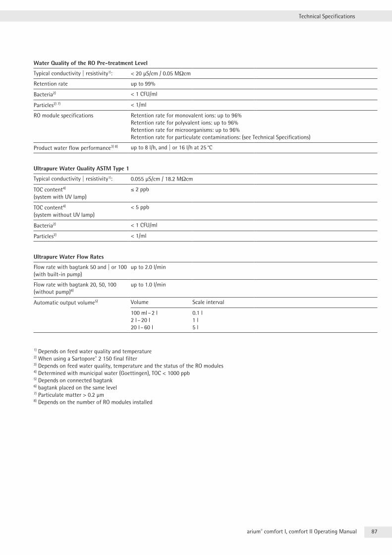
87arium® comfort I, comfort II Operating Manual
Technical Specifications
Water Quality of the RO Pre-treatment Level
Typical conductivity | resistivity1): < 20 µS/cm / 0 .05 MΩcm
Retention rate up to 99%
Bacteria2) < 1 CFU/ml
Particles2) 7) < 1/ml
RO module specifications Retention rate for monovalent ions: up to 96%Retention rate for polyvalent ions: up to 96%Retention rate for microorganisms: up to 96%Retention rate for particulate contaminations: (see Technical Specifications)
Product water flow performance3) 8) up to 8 l/h, and | or 16 l/h at 25 °C
Ultrapure Water Quality ASTM Type 1
Typical conductivity | resistivity1): 0 .055 µS/cm / 18 .2 MΩcm
TOC content4) (system with UV lamp)
< 2 ppb
TOC content4) (system without UV lamp)
< 5 ppb
Bacteria2) < 1 CFU/ml
Particles2) < 1/ml
Ultrapure Water Flow Rates
Flow rate with bagtank 50 and | or 100 (with built-in pump)
up to 2 .0 l/min
Flow rate with bagtank 20, 50, 100 (without pump)6)
up to 1 .0 l/min
Automatic output volume5) Volume Scale interval
100 ml – 2 l2 l – 20 l20 l – 60 l
0 .1 l1 l5 l
1) Depends on feed water quality and temperature2) When using a Sartopore® 2 150 final filter3) Depends on feed water quality, temperature and the status of the RO modules4) Determined with municipal water (Goettingen), TOC < 1000 ppb5) Depends on connected bagtank6) bagtank placed on the same level7) Particulate matter > 0 .2 µm8) Depends on the number of RO modules installed
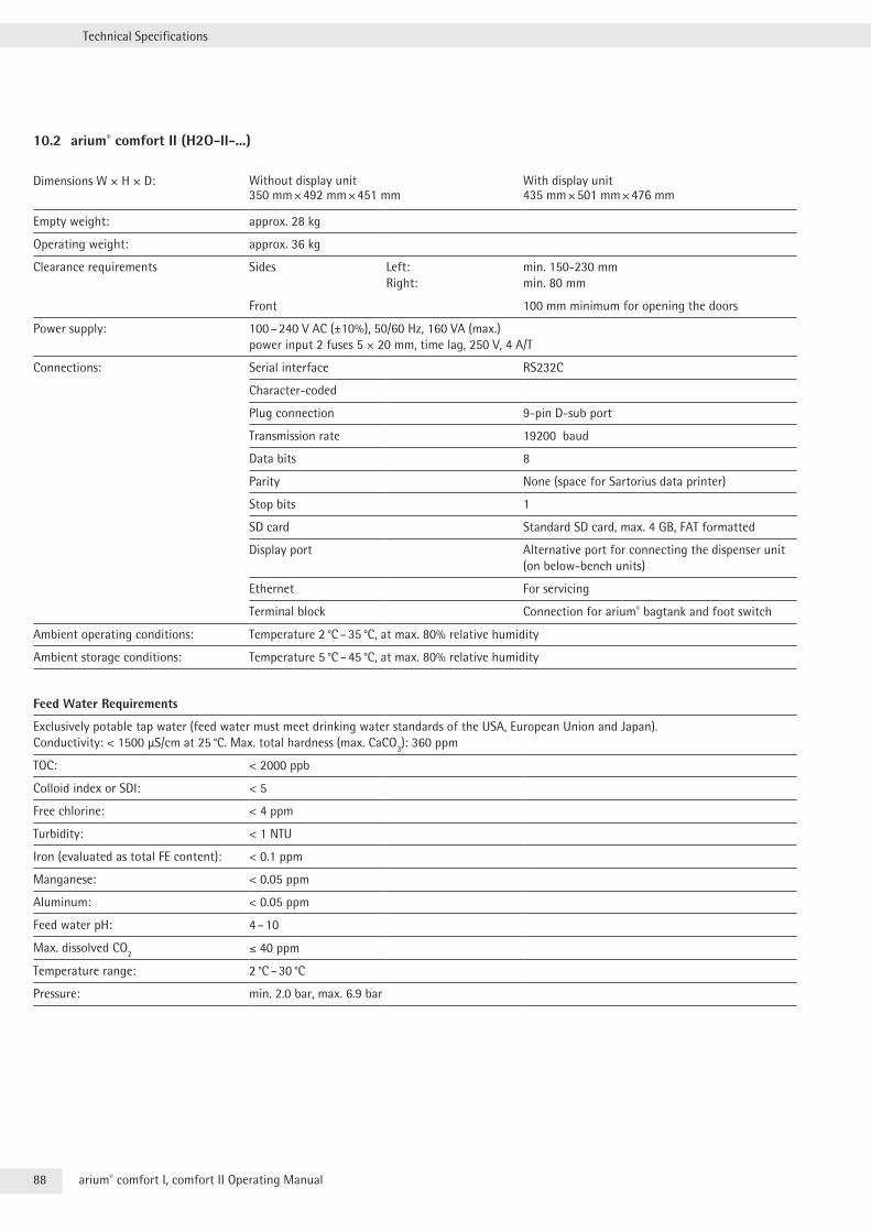
88 arium® comfort I, comfort II Operating Manual
Technical Specifications
10.2 arium® comfort II (H2O-II-...)
Dimensions W + H + D: Without display unit With display unit350 mm + 492 mm + 451 mm 435 mm + 501 mm + 476 mm
Empty weight: approx . 28 kg
Operating weight: approx . 36 kg
Clearance requirements Sides Left: Right:
min . 150-230 mm min . 80 mm
Front 100 mm minimum for opening the doors
Power supply: 100 – 240 V AC (±10%), 50/60 Hz, 160 VA (max .) power input 2 fuses 5 + 20 mm, time lag, 250 V, 4 A/T
Connections: Serial interface RS232C
Character-coded
Plug connection 9-pin D-sub port
Transmission rate 19200 baud
Data bits 8
Parity None (space for Sartorius data printer)
Stop bits 1
SD card Standard SD card, max . 4 GB, FAT formatted
Display port Alternative port for connecting the dispenser unit (on below-bench units)
Ethernet For servicing
Terminal block Connection for arium® bagtank and foot switch
Ambient operating conditions: Temperature 2 °C – 35 °C, at max . 80% relative humidity
Ambient storage conditions: Temperature 5 °C – 45 °C, at max . 80% relative humidity
Feed Water Requirements
Exclusively potable tap water (feed water must meet drinking water standards of the USA, European Union and Japan) . Conductivity: < 1500 µS/cm at 25 °C . Max . total hardness (max . CaCO3): 360 ppm
TOC: < 2000 ppb
Colloid index or SDI: < 5
Free chlorine: < 4 ppm
Turbidity: < 1 NTU
Iron (evaluated as total FE content): < 0 .1 ppm
Manganese: < 0 .05 ppm
Aluminum: < 0 .05 ppm
Feed water pH: 4 – 10
Max . dissolved CO2 < 40 ppm
Temperature range: 2 °C – 30 °C
Pressure: min . 2 .0 bar, max . 6 .9 bar
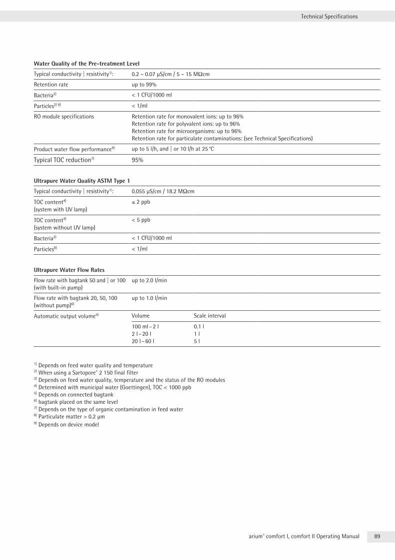
89arium® comfort I, comfort II Operating Manual
Technical Specifications
Water Quality of the Pre-treatment Level
Typical conductivity | resistivity1): 0 .2 – 0 .07 µS/cm / 5 – 15 MΩcm
Retention rate up to 99%
Bacteria2) < 1 CFU/1000 ml
Particles2) 8) < 1/ml
RO module specifications Retention rate for monovalent ions: up to 96%Retention rate for polyvalent ions: up to 96%Retention rate for microorganisms: up to 96%Retention rate for particulate contaminations: (see Technical Specifications)
Product water flow performance9) up to 5 l/h, and | or 10 l/h at 25 °C
Typical TOC reduction7) 95%
Ultrapure Water Quality ASTM Type 1
Typical conductivity | resistivity1): 0 .055 µS/cm / 18 .2 MΩcm
TOC content4) (system with UV lamp)
< 2 ppb
TOC content4) (system without UV lamp)
< 5 ppb
Bacteria2) < 1 CFU/1000 ml
Particles8) < 1/ml
Ultrapure Water Flow Rates
Flow rate with bagtank 50 and | or 100 (with built-in pump)
up to 2 .0 l/min
Flow rate with bagtank 20, 50, 100 (without pump)6)
up to 1 .0 l/min
Automatic output volume5) Volume Scale interval
100 ml – 2 l2 l – 20 l20 l – 60 l
0 .1 l1 l5 l
1) Depends on feed water quality and temperature2) When using a Sartopore® 2 150 final filter3) Depends on feed water quality, temperature and the status of the RO modules4) Determined with municipal water (Goettingen), TOC < 1000 ppb5) Depends on connected bagtank6) bagtank placed on the same level7) Depends on the type of organic contamination in feed water8) Particulate matter > 0 .2 µm9) Depends on device model
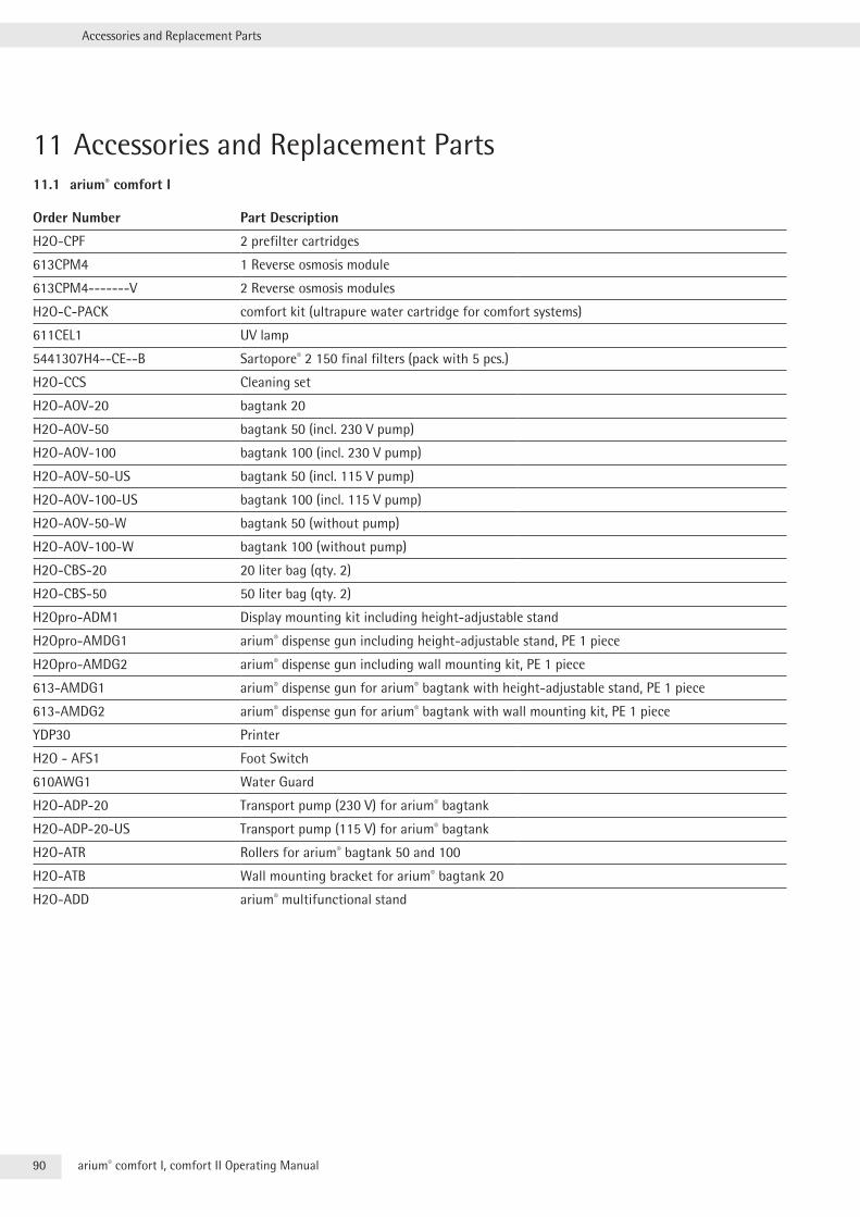
90 arium® comfort I, comfort II Operating Manual
Accessories and Replacement Parts
11 Accessories and Replacement Parts11.1 arium® comfort I
Order Number Part Description
H2O-CPF 2 prefilter cartridges
613CPM4 1 Reverse osmosis module
613CPM4-------V 2 Reverse osmosis modules
H2O-C-PACK comfort kit (ultrapure water cartridge for comfort systems)
611CEL1 UV lamp
5441307H4--CE--B Sartopore® 2 150 final filters (pack with 5 pcs .)
H2O-CCS Cleaning set
H2O-AOV-20 bagtank 20
H2O-AOV-50 bagtank 50 (incl . 230 V pump)
H2O-AOV-100 bagtank 100 (incl . 230 V pump)
H2O-AOV-50-US bagtank 50 (incl . 115 V pump)
H2O-AOV-100-US bagtank 100 (incl . 115 V pump)
H2O-AOV-50-W bagtank 50 (without pump)
H2O-AOV-100-W bagtank 100 (without pump)
H2O-CBS-20 20 liter bag (qty . 2)
H2O-CBS-50 50 liter bag (qty . 2)
H2Opro-ADM1 Display mounting kit including height-adjustable stand
H2Opro-AMDG1 arium® dispense gun including height-adjustable stand, PE 1 piece
H2Opro-AMDG2 arium® dispense gun including wall mounting kit, PE 1 piece
613-AMDG1 arium® dispense gun for arium® bagtank with height-adjustable stand, PE 1 piece
613-AMDG2 arium® dispense gun for arium® bagtank with wall mounting kit, PE 1 piece
YDP30 Printer
H2O - AFS1 Foot Switch
610AWG1 Water Guard
H2O-ADP-20 Transport pump (230 V) for arium® bagtank
H2O-ADP-20-US Transport pump (115 V) for arium® bagtank
H2O-ATR Rollers for arium® bagtank 50 and 100
H2O-ATB Wall mounting bracket for arium® bagtank 20
H2O-ADD arium® multifunctional stand
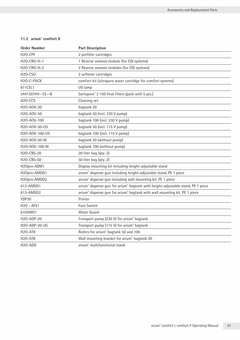
91arium® comfort I, comfort II Operating Manual
Accessories and Replacement Parts
11.2 arium® comfort II
Order Number Part Description
H2O-CPF 2 prefilter cartridges
H2O-CRO-H-1 1 Reverse osmosis module (for EDI systems)
H2O-CRO-H-2 2 Reverse osmosis modules (for EDI systems)
H2O-CSO 2 softener cartridges
H2O-C-PACK comfort kit (ultrapure water cartridge for comfort systems)
611CEL1 UV lamp
5441307H4--CE--B Sartopore® 2 150 final filters (pack with 5 pcs .)
H2O-CCS Cleaning set
H2O-AOV-20 bagtank 20
H2O-AOV-50 bagtank 50 (incl . 230 V pump)
H2O-AOV-100 bagtank 100 (incl . 230 V pump)
H2O-AOV-50-US bagtank 50 (incl . 115 V pump)
H2O-AOV-100-US bagtank 100 (incl . 115 V pump)
H2O-AOV-50-W bagtank 50 (without pump)
H2O-AOV-100-W bagtank 100 (without pump)
H2O-CBS-20 20 liter bag (qty . 2)
H2O-CBS-50 50 liter bag (qty . 2)
H2Opro-ADM1 Display mounting kit including height-adjustable stand
H2Opro-AMDG1 arium® dispense gun including height-adjustable stand, PE 1 piece
H2Opro-AMDG2 arium® dispense gun including wall mounting kit, PE 1 piece
613-AMDG1 arium® dispense gun for arium® bagtank with height-adjustable stand, PE 1 piece
613-AMDG2 arium® dispense gun for arium® bagtank with wall mounting kit, PE 1 piece
YDP30 Printer
H2O - AFS1 Foot Switch
610AWG1 Water Guard
H2O-ADP-20 Transport pump (230 V) for arium® bagtank
H2O-ADP-20-US Transport pump (115 V) for arium® bagtank
H2O-ATR Rollers for arium® bagtank 50 and 100
H2O-ATB Wall mounting bracket for arium® bagtank 20
H2O-ADD arium® multifunctional stand
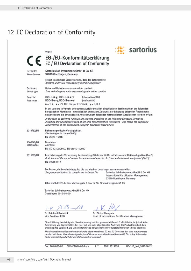
92 arium® comfort I, comfort II Operating Manual
EC Declaration of Conformity
12 EC Declaration of Conformity
04 | 2016
Printed in the EU on paper bleached without chlorine . | W Publication No .: WH26002-e160408
Last updated:
The information and figures contained in these instructions correspond to the version date specified below.Sartorius reserves the right to make changes to the technology, features, specifications and design of the equipment without notice.Masculine or feminine forms are used to facilitate legibility in these instructions and always simultaneously denote the other gender as well.
Copyright notice:This instruction manual, including all of its components, is protected by copyright.Any use beyond the limits of the copyright law is not permitted without our approval.This applies in particular to reprinting, translation and editing irrespective of the type of media used.
© Sartorius Germany
Sartorius Lab Instruments GmbH & Co. KGOtto-Brenner-Strasse 2037079 Goettingen, Germany
Phone: +49.551.308.0Fax: +49.551.308.3289www.sartorius.com