arinc 629 avionics databus
TRANSCRIPT

ARINC 629 Designed and Developed by Boeing Company
First deployed on Boeing 777 Jet-liner
Boeing worked with ARINC to create and release Specification
Specification was first adopted by AEEC in 1989
Supports a Multi-transmitter and Bi-directional approach to digital Data communications
Employs a protocol referred to as DATAC (Digital Autonomous Terminal Access Control)
ARINC 629 PROTOCOL

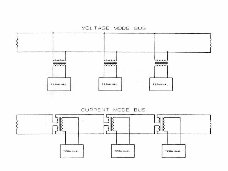
ARINC 629 DATA BUS
Time Division Multiplex
Linear Bus
Multiple Transmitter Access
2 Mbps Data Rate
Current Mode Coupling (Present implementation)
Fiber Optic Mode (Defined, Prototype implemented)

INTERFACING COUPLER WITH SYSTEM
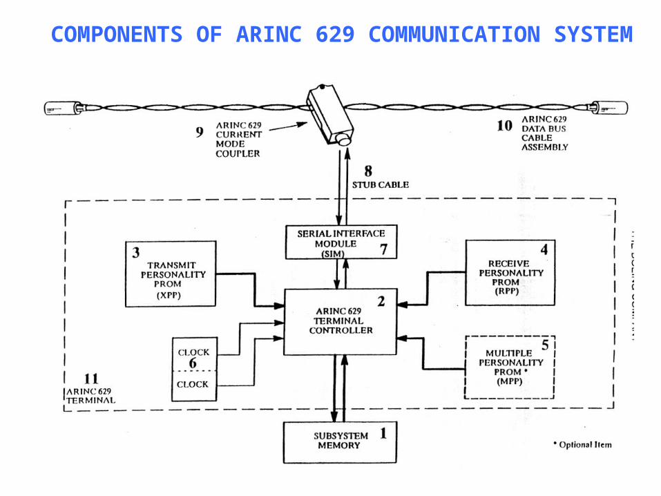
COMPONENTS OF ARINC 629 COMMUNICATION SYSTEM
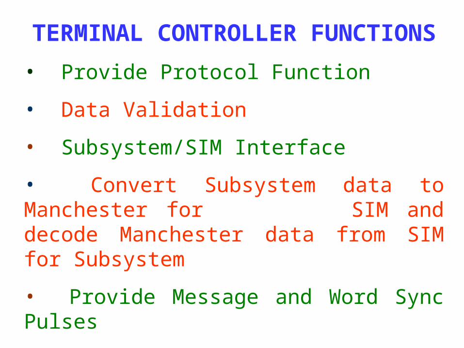
TERMINAL CONTROLLER FUNCTIONS
• Provide Protocol Function
• Data Validation
• Subsystem/SIM Interface
• Convert Subsystem data to Manchester for SIM and decode Manchester data from SIM for Subsystem
• Provide Message and Word Sync Pulses
• Provide Inter-Word string Gaps
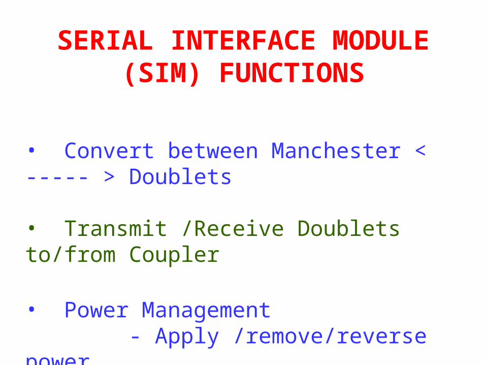
SERIAL INTERFACE MODULE (SIM) FUNCTIONS
• Convert between Manchester < ----- > Doublets
• Transmit /Receive Doublets to/from Coupler
• Power Management - Apply /remove/reverse power - Over current detection and shutdown
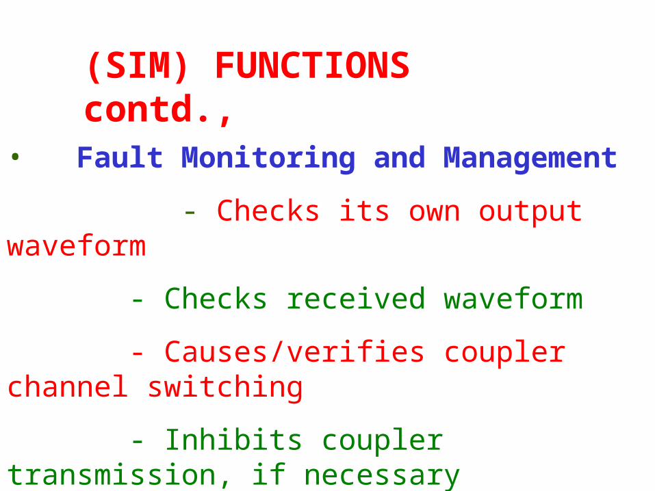
• Fault Monitoring and Management
- Checks its own output waveform
- Checks received waveform
- Causes/verifies coupler channel switching
- Inhibits coupler transmission, if necessary
- Outputs fault information to Terminal
Controller
(SIM) FUNCTIONS contd.,

CURRENT MODE COUPLER FUNCTIONS
• Provides Non-intrusive connection to the Bus
• Transmits/Receives Doublets onto/from the Bus
• Provides Low Impedance to Bus under all conditions
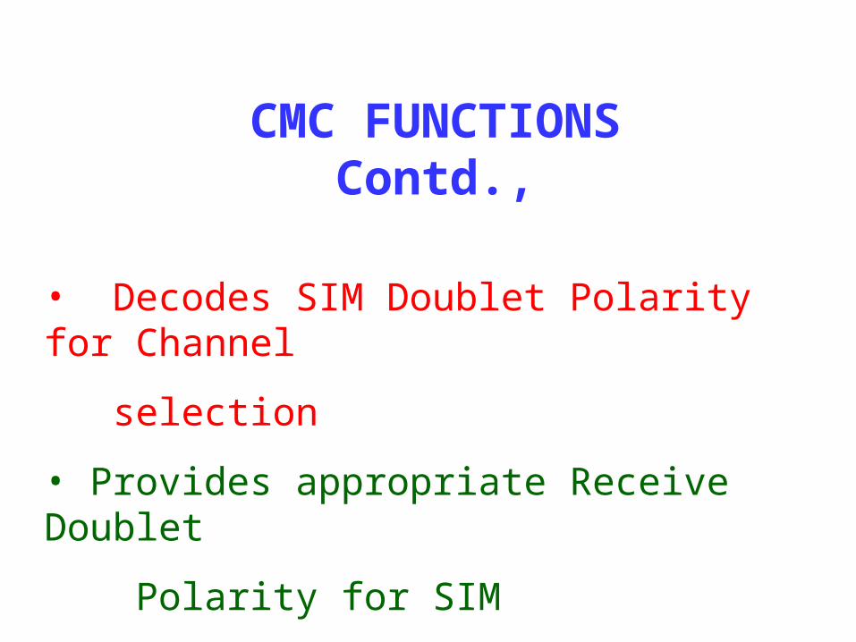
• Decodes SIM Doublet Polarity for Channel
selection
• Provides appropriate Receive Doublet
Polarity for SIM
• Shuts Down Transmitters on Power Reversal
CMC FUNCTIONS Contd.,
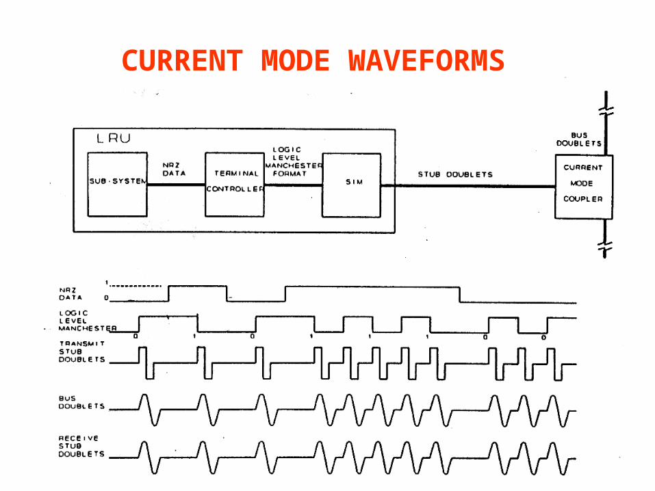
CURRENT MODE WAVEFORMS
ARINC 629 PROTOCOL
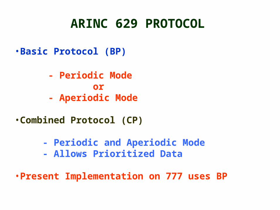
•Basic Protocol (BP)
- Periodic Mode or - Aperiodic Mode
•Combined Protocol (CP)
- Periodic and Aperiodic Mode - Allows Prioritized Data
•Present Implementation on 777 uses BP

Basic ProtocolProvides an equal priority access
for each terminal to transmit either Periodic or Aperiodic data
If no bus overload exists and transmission lengths are constant,terminals transmit at a constant interval (Periodic Mode)
If the bus is overloaded, it will automatically switch to an Aperiodic mode with no loss of data
Overload Characteristics provide continuous operation at 100% bus utilization with no throughput collapse

Combined Mode Protocol
Provides Priority Access for Periodic data transmission (Priority 1) and two levels of lower priority access for Aperiodic data transmission (lLevels 2 & 3)
At each level all terminals are given equal opportunity to access the bus
Allows substantial levels of Aperiodic data to be transmitted without risk of affecting the frequency of periodic transmission
BUS PROTOCOL CONCEPTS(BP)
• Presence of a carrier (transmission from a terminal) is used to inhibit all other transmitters
• Absence of a carrier – Signal for another terminal may begin to transmit

Because more than one terminal may begin to transmit when the Bus is free, a method of avoiding clashes must be used
Method used by ARINC 629 is called CSMA/CA
CSMA/CA is achieved by use of three timers - Transmit Interval (TI) - Terminal Gap (TG) - Synchronization Gap (SG)
Transmit Interval (TI)
- Global Bus Parameter - Selected as the inverse of the maximum update rate required for any data item - To conserve Bus Capacity, Data items with lesser update rate should be scheduled to be transmitted at update intervals that are multiples of the global TI. - For a particular terminal, TI begins the moment the terminal starts transmitting
- Once it has transmitted, it must wait the length of time specified by the TI before it can transmit again (0.5 to 64 ms)
Terminal Gap - Unique Timer assigned to each terminal on the Bus
- TG begins only after the SG has elapsed and only if no carrier is present - TG is reset by the presence of a carrier -
- TG range : 4 to 128 μs
-TG and SG cannot overlap in time, they must run consecutively
Synchronization Gap
- Global Access Parameter - SG is the second longest timer and is set to the same value in all terminals
- SG is chosen so that it is longer than the maximum length Terminal Gap on the Bus
- SG starts the moment the bus is quiet,it is reset if a carrier appears on the bus before it has elapsed - Once SG has elapsed, it cannot be reset by the presence of a carrier
- It can only be reset, when that terminal begins transmitting
Minimum Frame Time (MFT)
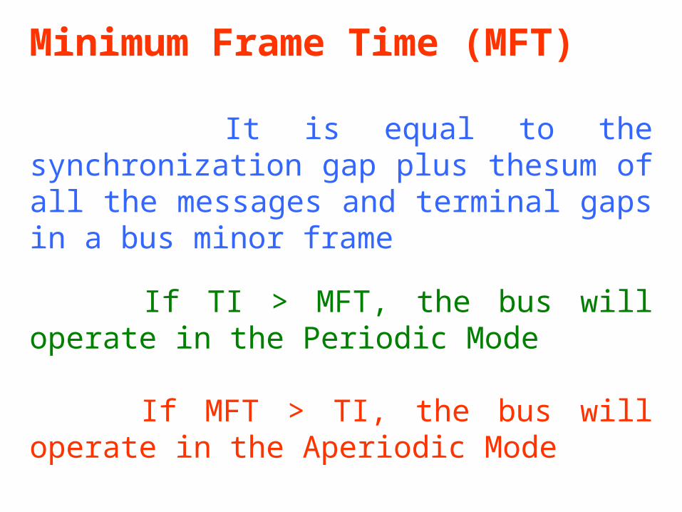
It is equal to the synchronization gap plus thesum of all the messages and terminal gaps in a bus minor frame
If TI > MFT, the bus will operate in the Periodic Mode
If MFT > TI, the bus will operate in the Aperiodic Mode
Periodic Mode Terminals will transmit in the order they powered up
Aperiodic Mode Terminals will always transmit in the order of shortest to longest TG
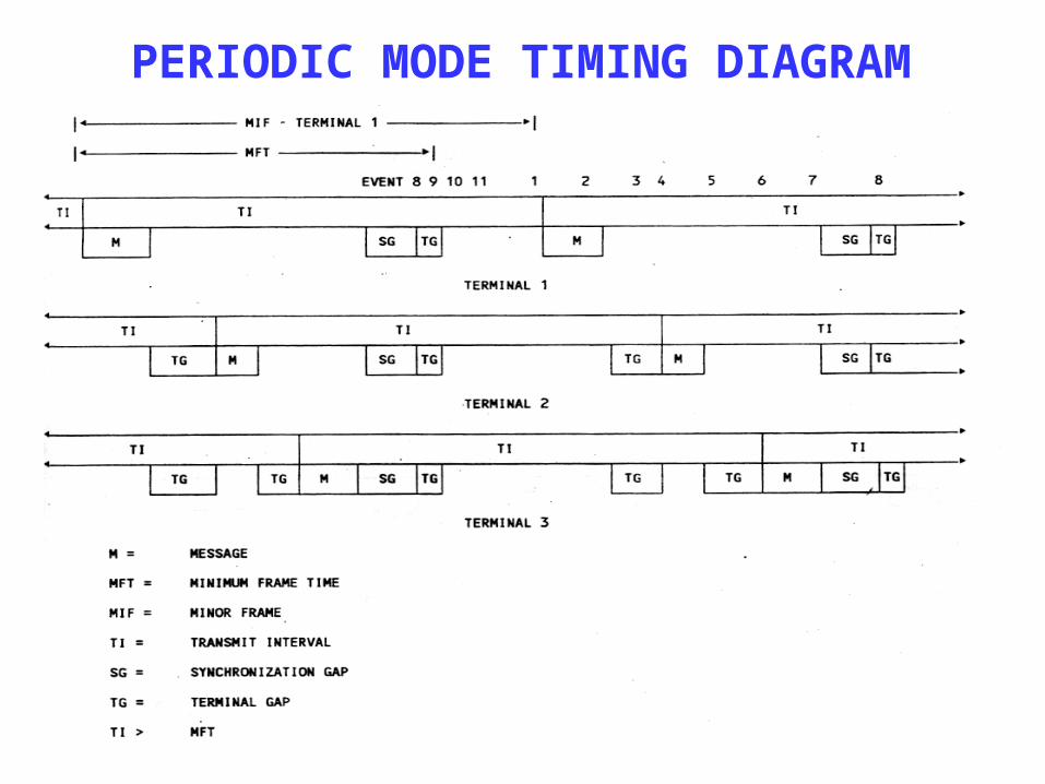
PERIODIC MODE TIMING DIAGRAM
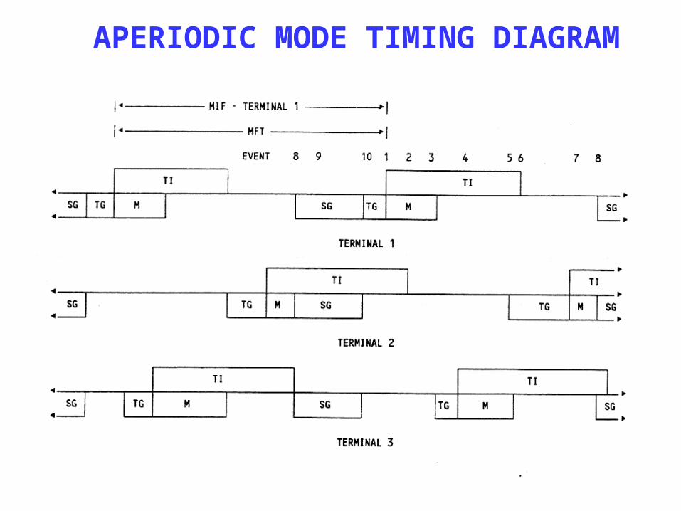
APERIODIC MODE TIMING DIAGRAM

TERMINAL ACCESS FLOWCHART

Message Scheduling
Two Message Scheduling Techniques
- Block Mode Scheduling - Independent Mode Scheduling
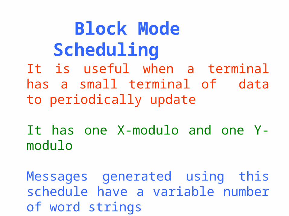
Block Mode Scheduling
It is useful when a terminal has a small terminal of data to periodically update
It has one X-modulo and one Y-modulo
Messages generated using this schedule have a variable number of word strings

A B C D
E
F G
0
1
2
0 1 2 3
X
Y
Messages:
A, B, C, DEF, G
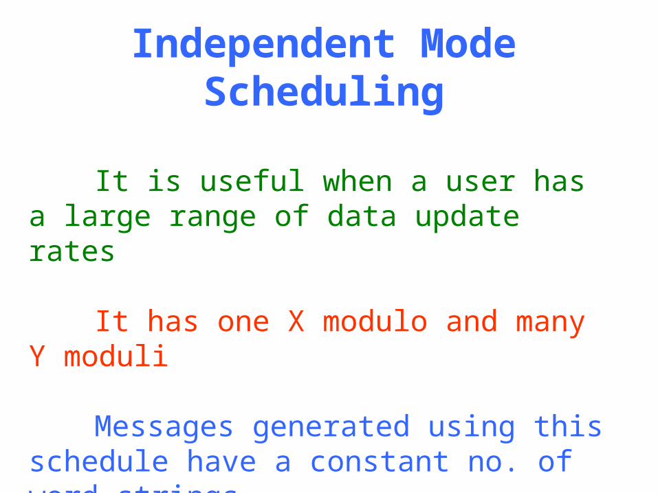
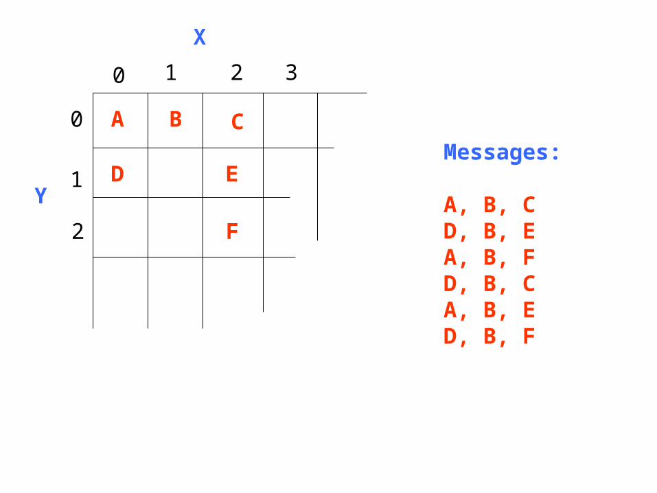
Independent Mode Scheduling
It is useful when a user has a large range of data update rates
It has one X modulo and many Y moduli
Messages generated using this schedule have a constant no. of word strings
A B C
D
F
0
1
2
0 1 2 3
YE
X
Messages:
A, B, CD, B, EA, B, FD, B, CA, B, ED, B, F
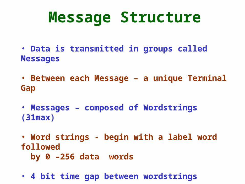
Message Structure
• Data is transmitted in groups called Messages
• Between each Message – a unique Terminal Gap
• Messages – composed of Wordstrings (31max)
• Word strings - begin with a label word followed by 0 –256 data words
• 4 bit time gap between wordstrings
• Min (1 label and no data word), Max (31 labels with 256 data words)

EXAMPLE OF A MESSAGE
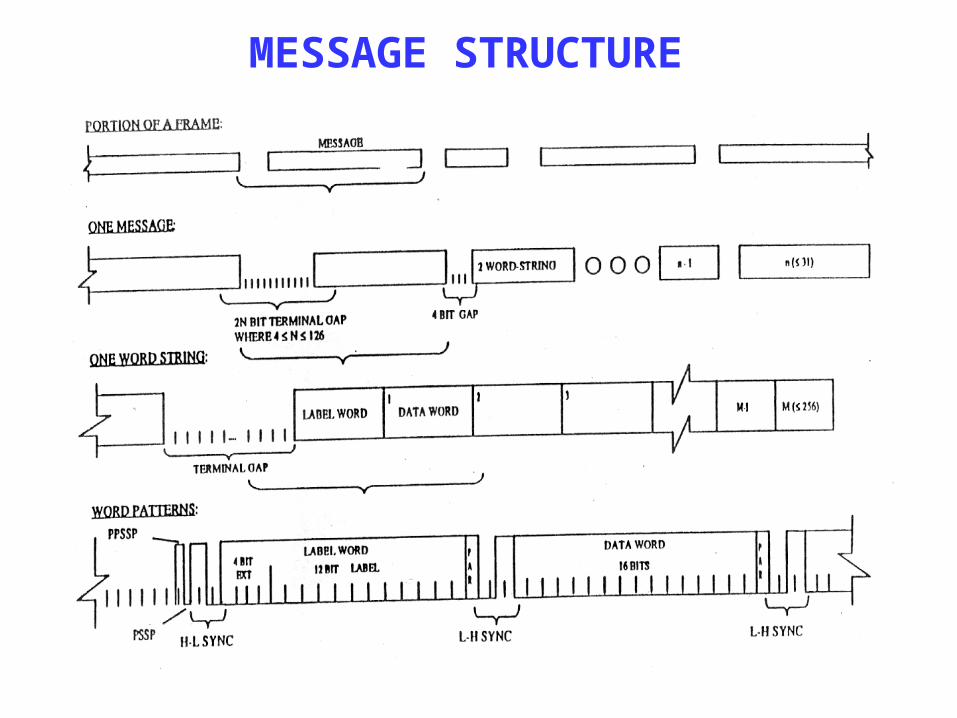
MESSAGE STRUCTURE
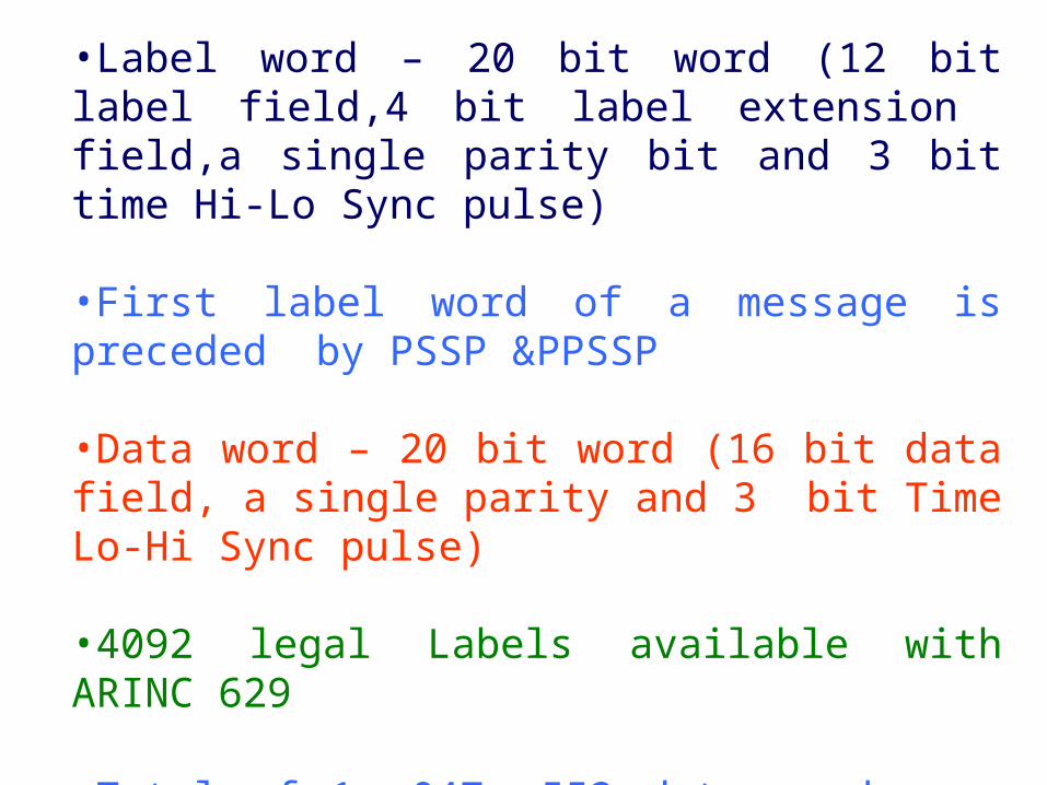
•Label word – 20 bit word (12 bit label field,4 bit label extension field,a single parity bit and 3 bit time Hi-Lo Sync pulse)
•First label word of a message is preceded by PSSP &PPSSP
•Data word – 20 bit word (16 bit data field, a single parity and 3 bit Time Lo-Hi Sync pulse)
•4092 legal Labels available with ARINC 629
•Total of 1, 047, 552 data words may be individually identified, because each label can have up to 256 data words after it

THANK YOU