argo argo g - montaza.lv pdfi/argo man en.pdf · argo argo g d811627a00100_03 28-01-11 istruzioni...
TRANSCRIPT

AR
GO
AR
GO
GD
8116
27A
0010
0_03
28-
01-1
1
ISTR
UZ
ION
I DI I
NST
ALL
AZ
ION
EIN
STA
LLA
TIO
N M
AN
UA
LIN
STR
UC
TIO
NS
D’IN
STA
LLA
TIO
NM
ON
TAG
EAN
LEIT
UN
GIN
STR
UC
CIO
NES
DE
INST
ALA
CIO
NIN
STA
LLA
TIEV
OO
RSC
HR
IFTE
N
AUTOMAZIONI PER PORTE SEZIONALI INDUSTRIALIOPERATORS FOR INDUSTRIAL SECTIONAL DOORSAUTOMATISMES POUR PORTES MULTI-LAMES INDUSTRIELLESAUTOMATISCHE ANTRIEBE FÜR INDUSTRIE-SEKTIONALTOREAUTOMATISMOS PARA PUERTAS SECCIONALES INDUSTRIALESAUTOMATISERINGEN VOOR INDUSTRIËLE OPDRACHTGERICHTE DEUREN
AR
GO
AR
GO
G
Attenzione! Leggere attentamente le “Avvertenze” all’interno! Caution! Read “Warnings” inside carefully! Attention! Veuillez lire attentivement les Avertissements qui se trouvent à l’intérieur! Achtung! Bitte lesen Sie aufmerksam die „Hinweise“ im Inneren! ¡Atención¡ Leer atentamente las “Advertencias” en el interior! Let op! Lees de “Waarschuwingen” aan de binnenkant zorgvuldig!
8 027908 3 5 5 7 4 4
5
6
7
8
4
3
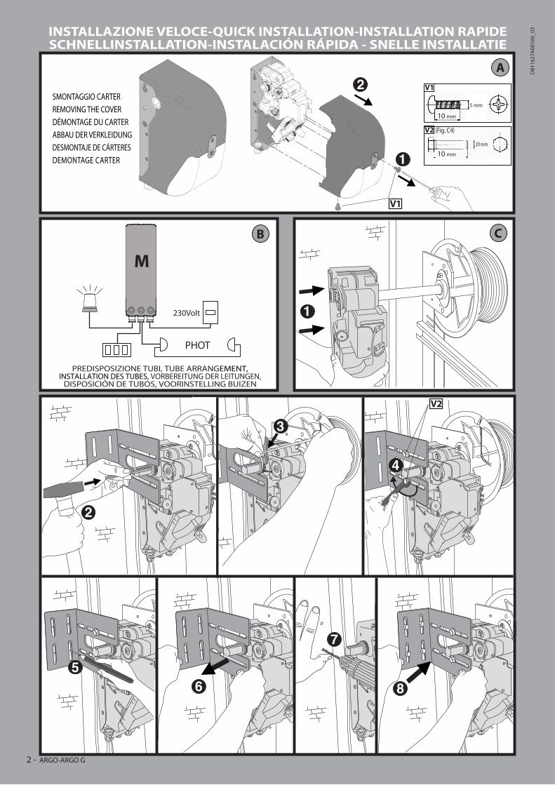
PREDISPOSIZIONE TUBI, TUBE ARRANGEMENT,INSTALLATION DES TUBES, VORBEREITUNG DER LEITUNGEN,
DISPOSICIÓN DE TUBOS, VOORINSTELLING BUIZEN
A
C
PHOT
230Volt
2
M
B
1
5 mm
10 mm
10 mm
1
2SMONTAGGIO CARTER
REMOVING THE COVER
DÉMONTAGE DU CARTER
ABBAU DER VERKLEIDUNG
DESMONTAJE DE CÁRTERES
DEMONTAGE CARTER
V1
20 mm
V2
V1
V2
(Fig. C4)
INSTALLAZIONE VELOCE-QUICK INSTALLATION-INSTALLATION RAPIDESCHNELLINSTALLATION-INSTALACIÓN RÁPIDA - SNELLE INSTALLATIE
2 - ARGO-ARGO G
D81
1627
A00
100_
03
ITALIA
NO
EN
GLIS
HFR
AN
ÇA
ISE
SPA
ÑO
LN
EDERLA
ND
SD
EU
TS
CH
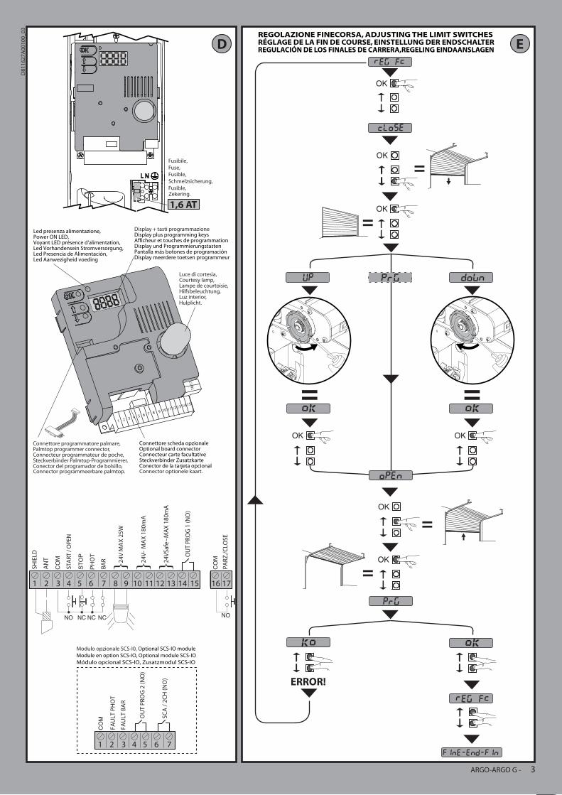
Connettore programmatore palmare,Palmtop programmer connector,Connecteur programmateur de poche,Steckverbinder Palmtop-Programmierer,Conector del programador de bolsillo,
Luce di cortesia,Courtesy lamp,Lampe de courtoisie,Hilfsbeleuchtung,Luz interior,
16
1 2 3 4 5 6 7 8 9 10 11 12 13 14 15
17
Display + tasti programmazioneDisplay plus programming keysAfficheur et touches de programmationDisplay und ProgrammierungstastenPantalla más botones de programaciónDisplay meerdere toetsen programmeur
Modulo opzionale SCS-I0, Optional SCS-IO module
Module en option SCS-IO, Optional module SCS-IO
Módulo opcional SCS-IO, Zusatzmodul SCS-IO
Led presenza alimentazione, Power ON LED,Voyant LED présence d'alimentation,Led Vorhandensein Stromversorgung,Led Presencia de Alimentación,Led Aanwezigheid voeding
Connettore scheda opzionaleOptional board connectorConnecteur carte facultativeSteckverbinder ZusatzkarteConector de la tarjeta opcional
D
1 2 3 4 5 6 7
OU
T P
RO
G 2
(N
O)
SC
A /
2C
H (
NO
)
FA
UL
T P
HO
T
FA
UL
T B
AR
1 2 3 4 5 6 7 8 9 10 11 12 13 14 15 16 17
24
VS
afe
M
AX
18
0m
A
OU
T P
RO
G 1
(NO
)
PA
RZ
./C
LOSE
24
V
MA
X 1
80
mA
24
V M
AX
25
W
AN
T
SH
IEL
D
STA
RT
/ O
PEN
BA
R
EREGOLAZIONE FINECORSA, ADJUSTING THE LIMIT SWITCHESRÉGLAGE DE LA FIN DE COURSE, EINSTELLUNG DER ENDSCHALTERREGULACIÓN DE LOS FINALES DE CARRERA,REGELING EINDAANSLAGEN
Fusibile,
Fuse,
Fusible,
Schmelzsicherung,
Fusible,
1,6 ATZekering.
Hulplicht.
Connector programmeerbare palmtop. Connector optionele kaart.
ARGO-ARGO G - 3
D81
1627
A00
100_
03
F
A
B
OK x 2
OK
x 2
+
OK
OK
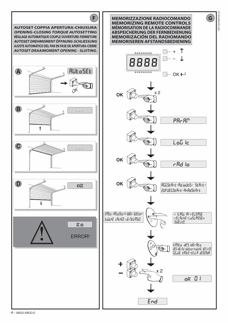
AUTOSET COPPIA APERTURA-CHIUSURA
OPENING-CLOSING TORQUE AUTOSETTINGRÉGLAGE AUTOMATIQUE COUPLE OUVERTURE-FERMETURE
AUTOSET DREHMOMENT ÖFFNUNG-SCHLIESSUNGAJUSTE AUTOMATICO DEL PAR EN FASE DE APERTURA-CIERRE
AUTOSET DRAAIMOMENT OPENING - SLUITING.
G
C
D
MEMORIZZAZIONE RADIOCOMANDOMEMORIZING REMOTE CONTROLSMÉMORISATION DE LA RADIOCOMMANDEABSPEICHERUNG DER FERNBEDIENUNGMEMORIZACIÓN DEL RADIOMANDOMEMORISEREN AFSTANDSBEDIENING
4 - ARGO-ARGO G
D81
1627
A00
100_
03
0
50
100
150
200
250
300
350
400
1 1,5 2 2,5 3 3,5 4 4,5 5 5,5 6
I
J
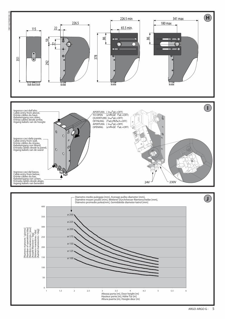
H
Diametro medio puleggia [mm], Average pulley diameter [mm],Diamètre moyen poulie [mm], Mittlerer Durchmesser Riemenscheibe [mm],Diámetro promedio polea[mm], Gemiddelde diameter katrol [mm]
[Nu
mer
o m
ano
vre
/ g
iorn
o]
[Nu
mb
er o
f op
erat
ion
s/d
ay]
[No
mb
re m
anœ
uvr
es /
jou
r][A
nza
hl M
anö
ver
/ Tag
][N
úm
ero
man
iob
ras
/ d
ía]
[Aan
tal m
ano
euvr
es /
dag
]
Altezza porta [m], Door height [m]Hauteur porte [m], Höhe Tür [m]Altura puerta [m], Hoogte deur [m]
ø 250
ø 225
ø 200
ø 175
ø 150
ø 125
ø 100
Ingresso cavi dall'alto,Cable entry from above,Entrée câbles du haut,Kabeleingang von oben,Entraa cables desde arriba,Ingang kabels van de hoogte
Ingresso cavi dalla parete,Cable entry from wall,Entrée câbles du réseau,Kabeleingang von Wand,Entrada cables desde la pared,Ingang kabels van de wand
Ingresso cavi dal basso,Cable entry from below,Entrée câbles du bas,Kabeleingang von unten,Entrada cables desde abajo,Ingang kabels van beneden 230V24V
APERTURA ( =OFF)TO OPEN ( =OFF)OUVERTURE ( =OFF)ÖFFNUNG ( =OFF)APERTURA ( =OFF)OPENING ( =OFF)
115
351
226.5
5929
2
77
22
86
378
65.5 min.
226.5 min
86
180 max341 max
ARGO-ARGO G - 5
D81
1627
A00
100_
03
M
L
K
Reeds gememoriseerde afstandsbediening Reeds gememoriseerde afstandsbediening Te memoriseren afstandsbediening Te memoriseren afstandsbediening
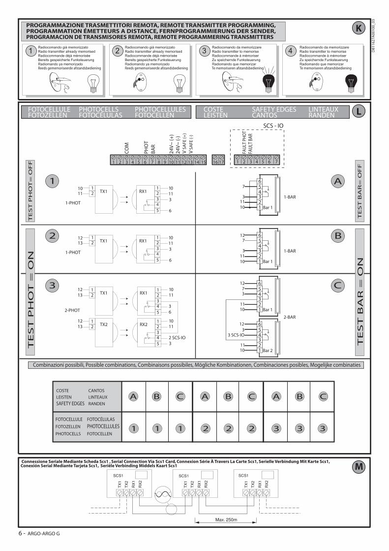
PROGRAMMAZIONE TRASMETTITORI REMOTA, REMOTE TRANSMITTER PROGRAMMING,PROGRAMMATION ÉMETTEURS A DISTANCE, FERNPROGRAMMIERUNG DER SENDER,PROGRAMACION DE TRANSMISORES REMOTA, REMOTE PROGRAMMERING TRANSMITTERS
Connessione Seriale Mediante Scheda Scs1 , Serial Connection Via Scs1 Card, Connexion Série À Travers La Carte Scs1, Serielle Verbindung Mit Karte Scs1, Conexión Serial Mediante Tarjeta Scs1, Seriële Verbinding Middels Kaart Scs1
1 2 3 4 5 6 7 8 9 10 11 12 13 14 15 16 17 1 2 3 4 5 6 7
CO
M
PH
OT
BA
R
FAU
LT B
AR
24
V~
(+
)
24
V~
(-)
FAU
LT P
HO
T
SCS - IO
VS
AF
E (
+)
VS
AF
E (
-)
FOTOCELLULEFOTOZELLEN
PHOTOCELLSFOTOCÉLULAS
PHOTOCELLULESFOTOCELLEN
COSTELEISTEN
SAFETY EDGESCANTOS
LINTEAUXRANDEN
12
1234
5
1011
10113
6
TX1 RX1
1-PHOT
12
1234
5
1213
10113
6
TX1 RX1
1-PHOT
1-BAR
Bar 1123456
1011
7
1011
3
127
3
Bar 112
456
2-BAR
12
12345
1213
1011
36
TX1 RX1
2-PHOT
12
12345
1213
1011
2 SCS-IO3
TX2 RX2
Bar 1123456
1011
37
12
Bar 2123456
1011
3 SCS-IO3
12
Combinazioni possibili, Possible combinations, Combinaisons possibiles, Mögliche Kombinationen, Combinaciones posibles, Mogelijke combinaties
TE
ST
PH
OT
= O
NT
ES
T P
HO
T=
OF
F
TE
ST
BA
R=
OF
FT
ES
T B
AR
= O
N
1
A B C A B C A B C
11 1 22 2 33 3
2
3
A
B
C
FOTOCELLULE
FOTOZELLEN
PHOTOCELLS
FOTOCÉLULAS
PHOTOCELLULESFOTOCELLEN
COSTE
LEISTEN
SAFETY EDGES
CANTOS
LINTEAUX
RANDEN
3 1-BAR
6 - ARGO-ARGO G
D81
1627
A00
100_
03
OK
OK
OK
OK
OK
- +
- +
- +
- +
OK OK OK
+/-
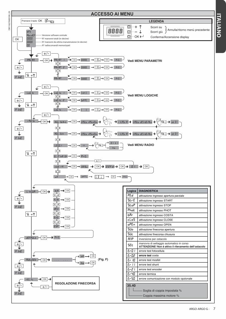
Vedi MENU PARAMETRI
Vedi MENU LOGICHE
Vedi MENU RADIO
ACCESSO AI MENU
Annulla/ritorno menù precedente
Conferma/Accensione display
Scorri su
Scorri giù
DIAGNOSTICA
attivazione ingresso apertura parziale
attivazione ingresso START
attivazione ingresso STOP
attivazione ingresso PHOT
attivazione ingresso COSTA
attivazione ingresso CLOSE
attivazione ingresso OPEN
attivazione finecorsa apertura
attivazione finecorsa chiusura
errore test fotocellula
errore test
inversione per ostacolo
manovra di settaggio automatico in corsoATTENZIONE! Non è attivo il rilevamento dell’ostacolo
Logica
35.40
Soglia di coppia impostata %
Coppia massima motore %
Versione software centrale
N° manovre totali (in decine)
N° manovre da ultima manutenzione (in decine)
N° radiocomandi memorizzati
errore test costa
errore test mosfet
errore test shunt
errore test encoder
errore termica
errore comunicazione con modulo opzionale
REGOLAZIONE FINECORSA
(Fig. F)
ITALIA
NO
ARGO-ARGO G - 7
D81
1627
A00
100_
03
OK
OK
OK
OK
OK
- +
- +
- +
- +
OK OK OK
+/-
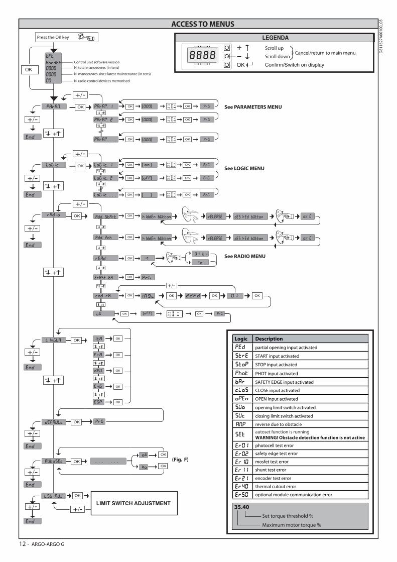
See PARAMETERS MENU
See LOGIC MENU
See RADIO MENU
ACCESS TO MENUS
Cancel/return to main menuScroll up
Scroll down
Description
partial opening input activated
START input activated
STOP input activated
PHOT input activated
SAFETY EDGE input activated
CLOSE input activated
OPEN input activated
opening limit switch activated
closing limit switch activated
photocell test error
safety edge test error
reverse due to obstacle
autoset function is running
WARNING! Obstacle detection function is not active
Logic
35.40
Set torque threshold %
Maximum motor torque %
mosfet test error
shunt test error
encoder test error
thermal cutout error
optional module communication error
(Fig. F)
LIMIT SWITCH ADJUSTMENT
Control unit software version
N. total manoeuvres (in tens)
N. manoeuvres since latest maintenance (in tens)
N. radio control devices memorised
Press the OK key
Confirm/Switch on display
12 - ARGO-ARGO G
D81
1627
A00
100_
03
EN
GLIS
HINSTALLER WARNINGS
Anything that is not explicitly provided for in the installation ma-nual is not allowed. The operator’s proper operation can only be guaranteed if the information given is complied with. The Firm shall not be answerable for damage caused by failure to comply with the instructions featured herein.While we will not alter the product’s essential features, the Firm re-serves the right, at any time, to make those changes deemed oppor-tune to improve the product from a technical, design or commercial point of view, and will not be required to update this publication accordingly.
WARNING! Important safety instructions. Carefully read and comply with all the warnings and instructions that come with the product as incorrect installation can cause injury to people and animals and damage to proper-ty. The warnings and instructions give important information regarding safety, installation, use and maintenance. Keep hold of instructions so that you can attach them to the technical "le and keep them handy for future reference.
GENERAL SAFETYThis product has been designed and built solely for the purpose indicated herein. Uses other than those indicated herein might cause damage to the product and create a hazard.- The units making up the machine and its installation must meet the requirements of the following European Directives, where applicable: 2004/108/EC, 2006/95/EC, 2006/42/EC, 89/106/EC, 99/05/EC and later amendments. For all countries outside the EEC, it is advisable to comply with the standards mentioned, in addition to any national standards in force, to achieve a good level of safety.
- The Manufacturer of this product (hereinafter referred to as the “Firm”) disclaims all responsibility resulting from improper use or any use other than that for which the product has been designed, as indicated herein, as well as for failure to apply Good Practice in the construction of entry systems (doors, gates, etc.) and for deformation that could occur during use.
- Installation must be carried out by quali�ed personnel (professional installer, according to EN 12635), in compliance with Good Practice and current code.
- Before commencing installation, check the product for damage.- Before installing the product, make all structural changes required to produce safety gaps and to provide protection from or isolate all crushing, shearing and dragging hazard areas and danger zones in general. Check that the existing structure meets the necessary strength and stability requirements.
- The Firm is not responsible for failure to apply Good Practice in the construction and maintenance of the doors, gates, etc. to be motorized, or for deformation that might occur during use.
- Make sure the stated temperature range is compatible with the site in which the automated system is due to be installed.
- Do not install this product in an explosive atmosphere: the presence of �ammable fumes or gas constitutes a serious safety hazard.
- Disconnect the electricity supply before performing any work on the system. Also disconnect bu�er batteries, if any are connected.
- Before connecting the power supply, make sure the product’s ratings match the mains ratings and that a suitable residual current circuit breaker and overcurrent protection device have been installed upline from the electrical system. Have the automated system’s mains power supply �tted with a switch or omnipolar thermal-magnetic circuit breaker with a contact separation of at least 3.0mm and any other equipment required by code.
- Make sure that upline from the mains power supply there is a residual current circuit breaker that trips at no more than 0.03A as well as any other equipment required by code.
- Make sure the earth system has been installed correctly: earth all the metal parts belonging to the entry system (doors, gates, etc.) and all parts of the system featuring an earth terminal.
- Installation must be carried out using safety devices and controls that meet standards EN 12978 and EN 12453.
- Impact forces can be reduced by using deformable edges.- In the event impact forces exceed the values laid down by the relevant standards, apply electro-sensitive or pressure-sensitive devices.
- Apply all safety devices (photocells, safety edges, etc.) required to keep the area free of impact, crushing, dragging and shearing hazards. Bear in mind the standards and directives in force, Good Practice criteria, intended use, the in-stallation environment, the operating logic of the system and forces generated by the automated system.
- Apply all signs required by current code to identify hazardous areas (residual risks). All installations must be visibly identi�ed in compliance with the provisions of standard EN 13241-1.
- This product cannot be installed on leaves incorporating doors (unless the motor can be activated only when the door is closed).
- If the automated system is installed at a height of less than 2.5 m or is accessible, the electrical and mechanical parts must be suitably protected.
- Install any �xed controls in a position where they will not cause a hazard, away from moving parts. More speci�cally, hold-to-run controls must be positioned within direct sight of the part being controlled and, unless they are key operated, must be installed at a height of at least 1.5 m and in a place where they cannot be reached by the public.
- Apply at least one warning light (�ashing light) in a visible position, and also attach a Warning sign to the structure.
- Attach a label near the operating device, in a permanent fashion, with information on how to operate the automated system’s manual release.
- Make sure that, during operation, mechanical risks are avoided or relevant protec-tive measures taken and, more speci�cally, that nothing can be banged, crushed, caught or cut between the part being operated and surrounding parts.
- Once installation is complete, make sure the motor automation settings are correct and that the safety and release systems are working properly.
- Only use original spare parts for any maintenance or repair work. The Firm di-sclaims all responsibility for the correct operation and safety of the automated system if parts from other manufacturers are used.
- Do not make any modi�cations to the automated system’s components unless explicitly authorized by the Firm.
- Instruct the system’s user on what residual risks may be encountered, on the control systems that have been applied and on how to open the system manually in an emergency. give the user guide to the end user.
- Dispose of packaging materials (plastic, cardboard, polystyrene, etc.) in accor-dance with the provisions of the laws in force. Keep nylon bags and polystyrene out of reach of children.
WIRINGWARNING! For connection to the mains power supply, use a multicore cable with a cross-sectional area of at least 4x1.5mm2 of the kind provided for by the regulations mentioned above (by way of example, type H05 VV-F cable can be used with a cross-sectional area of 4x1.5mm2). To connect auxiliary equipment, use wires with a cross-sectional area of at least 0.5 mm2.- Only use pushbuttons with a capacity of 10A-250V or more.- Wires must be secured with additional fastening near the terminals (for example,
using cable clamps) in order to keep live parts well separated from safety extra low voltage parts.
- During installation, the power cable must be stripped to allow the earth wire to be connected to the relevant terminal, while leaving the live wires as short as possible. The earth wire must be the last to be pulled taut in the event the cable’s fastening device comes loose.
WARNING! safety extra low voltage wires must be kept physically separate from low voltage wires.Only quali�ed personnel (professional installer) should be allowed to access live parts.
CHECKING THE AUTOMATED SYSTEM AND MAINTENANCEBefore the automated system is �nally put into operation, and during maintenance work, perform the following checks meticulously:- Make sure all components are fastened securely.- Check starting and stopping operations in the case of manual control.- Check the logic for normal or personalized operation.- For sliding gates only: check that the rack and pinion mesh correctly with 2 mm of play; keep the track the gate slides on clean and free of debris at all times.
- Check that all safety devices (photocells, safety edges, etc.) are working properly and that the anti-crush safety device is set correctly, making sure that the force of impact measured at the points provided for by standard EN 12445 is lower than the value laid down by standard EN 12453.
- Make sure that the emergency operation works, where this feature is provi-ded.
- Check opening and closing operations with the control devices applied.- Check that electrical connections and cabling are intact, making extra sure that insulating sheaths and cable glands are undamaged.
- While performing maintenance, clean the photocells’ optics.- When the automated system is out of service for any length of time, activate the emergency release (see “EMERGENCY OPERATION” section) so that the operated part is made idle, thus allowing the gate to be opened and closed manually.
SCRAPPINGMaterials must be disposed of in accordance with the regulations in force. There are no particular hazards or risks involved in scrapping the automated system. For the purpose of recycling, it is best to separate dismantled parts into like materials (electrical parts - copper - aluminium - plastic - etc.).
DISMANTLINGIf the automated system is being dismantled in order to be reassembled at another site, you are required to:- Cut o� the power and disconnect the whole electrical system.- Remove the actuator from the base it is mounted on.- Remove all the installation’s components.- See to the replacement of any components that cannot be removed or happen to be damaged.
AVVERTENZE PER L’INSTALLATORE D811766_02 ARGO-ARGO G - 13
D81
1627
A00
100_
03
INSTALLATION MANUAL
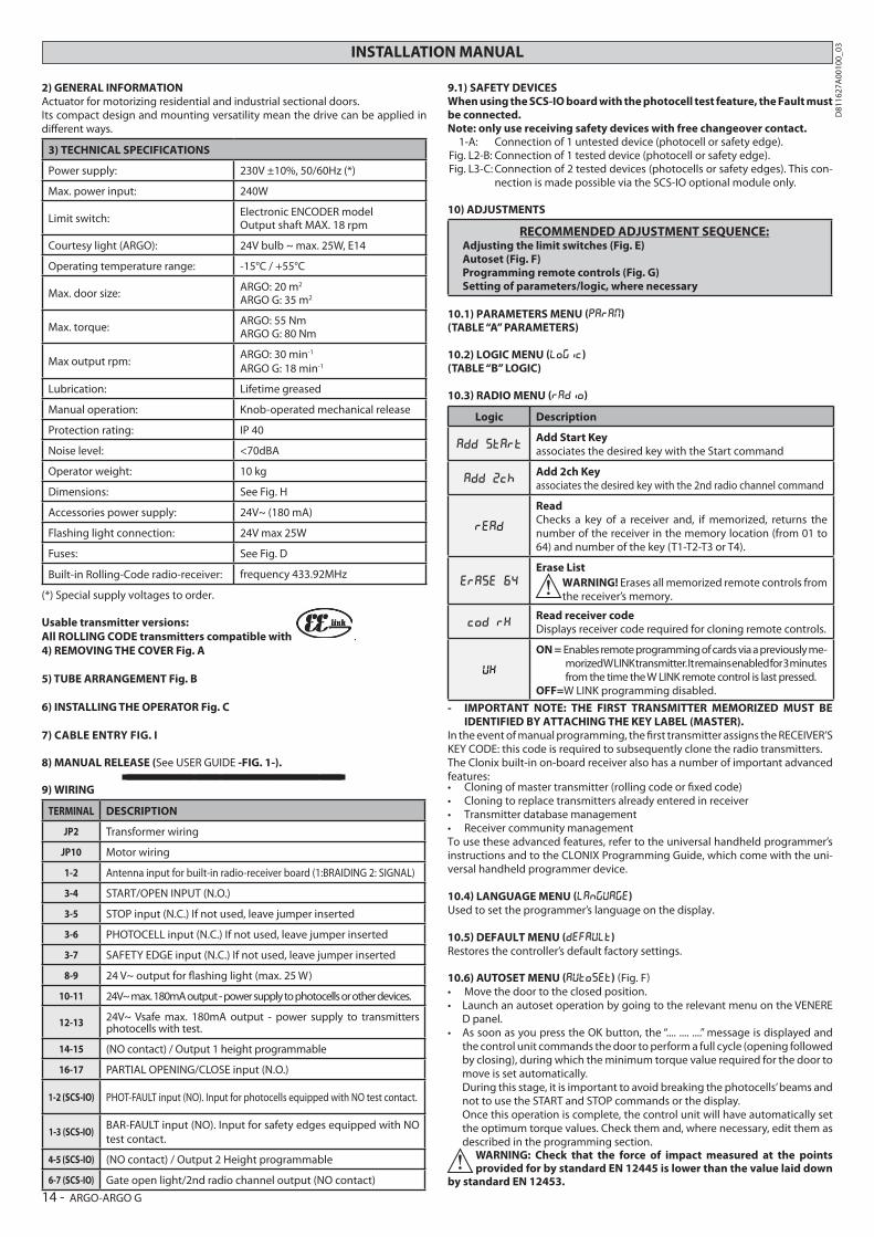
2) GENERAL INFORMATIONActuator for motorizing residential and industrial sectional doors.Its compact design and mounting versatility mean the drive can be applied in di!erent ways.
3) TECHNICAL SPECIFICATIONS
Power supply: 230V ±10%, 50/60Hz (*)
Max. power input: 240W
Limit switch:Electronic ENCODER modelOutput shaft MAX. 18 rpm
Courtesy light (ARGO): 24V bulb ~ max. 25W, E14
Operating temperature range: -15°C / +55°C
Max. door size:ARGO: 20 m2
ARGO G: 35 m2
Max. torque:ARGO: 55 NmARGO G: 80 Nm
Max output rpm:ARGO: 30 min-1
ARGO G: 18 min-1
Lubrication: Lifetime greased
Manual operation: Knob-operated mechanical release
Protection rating: IP 40
Noise level: <70dBA
Operator weight: 10 kg
Dimensions: See Fig. H
Accessories power supply: 24V~ (180 mA)
Flashing light connection: 24V max 25W
Fuses: See Fig. D
Built-in Rolling-Code radio-receiver: frequency 433.92MHz
(*) Special supply voltages to order.
Usable transmitter versions:All ROLLING CODE transmitters compatible with .4) REMOVING THE COVER Fig. A
5) TUBE ARRANGEMENT Fig. B
6) INSTALLING THE OPERATOR Fig. C 7) CABLE ENTRY FIG. I
8) MANUAL RELEASE (See USER GUIDE -FIG. 1-).----------------------------------------------------------
9) WIRING
TERMINAL DESCRIPTION
JP2 Transformer wiring
JP10 Motor wiring
1-2 Antenna input for built-in radio-receiver board (1:BRAIDING 2: SIGNAL)
3-4 START/OPEN INPUT (N.O.)
3-5 STOP input (N.C.) If not used, leave jumper inserted
3-6 PHOTOCELL input (N.C.) If not used, leave jumper inserted
3-7 SAFETY EDGE input (N.C.) If not used, leave jumper inserted
8-9 24 V~ output for $ashing light (max. 25 W)
10-11 24V~ max. 180mA output - power supply to photocells or other devices.
12-13 24V~ Vsafe max. 180mA output - power supply to transmitters photocells with test.
14-15 (NO contact) / Output 1 height programmable
16-17 PARTIAL OPENING/CLOSE input (N.O.)
1-2 (SCS-IO) PHOT-FAULT input (NO). Input for photocells equipped with NO test contact.
1-3 (SCS-IO)BAR-FAULT input (NO). Input for safety edges equipped with NO test contact.
4-5 (SCS-IO) (NO contact) / Output 2 Height programmable
6-7 (SCS-IO) Gate open light/2nd radio channel output (NO contact)
9.1) SAFETY DEVICESWhen using the SCS-IO board with the photocell test feature, the Fault must be connected. Note: only use receiving safety devices with free changeover contact. 1-A: Connection of 1 untested device (photocell or safety edge).Fig. L2-B: Connection of 1 tested device (photocell or safety edge).Fig. L3-C: Connection of 2 tested devices (photocells or safety edges). This con-
nection is made possible via the SCS-IO optional module only.
10) ADJUSTMENTS
RECOMMENDED ADJUSTMENT SEQUENCE:Adjusting the limit switches (Fig. E)Autoset (Fig. F)Programming remote controls (Fig. G)Setting of parameters/logic, where necessary
10.1) PARAMETERS MENU (param)(TABLE “A” PARAMETERS)
10.2) LOGIC MENU (logic)(TABLE “B” LOGIC)
10.3) RADIO MENU (RADIO)
Logic Description
add startAdd Start Keyassociates the desired key with the Start command
add 2chAdd 2ch Keyassociates the desired key with the 2nd radio channel command
read
ReadChecks a key of a receiver and, if memorized, returns the number of the receiver in the memory location (from 01 to 64) and number of the key (T1-T2-T3 or T4).
erase 64
Erase ListWARNING! Erases all memorized remote controls from the receiver’s memory.
cod RXRead receiver codeDisplays receiver code required for cloning remote controls.
uk
ON = Enables remote programming of cards via a previously me-morized W LINK transmitter. It remains enabled for 3 minutes from the time the W LINK remote control is last pressed.
OFF=W LINK programming disabled.
- IMPORTANT NOTE: THE FIRST TRANSMITTER MEMORIZED MUST BE IDENTIFIED BY ATTACHING THE KEY LABEL (MASTER).
In the event of manual programming, the &rst transmitter assigns the RECEIVER’S KEY CODE: this code is required to subsequently clone the radio transmitters.The Clonix built-in on-board receiver also has a number of important advanced features:
To use these advanced features, refer to the universal handheld programmer’s instructions and to the CLONIX Programming Guide, which come with the uni-versal handheld programmer device.
10.4) LANGUAGE MENU (language)Used to set the programmer’s language on the display. 10.5) DEFAULT MENU (default)Restores the controller’s default factory settings.
10.6) AUTOSET MENU (Autoset) (Fig. F)
D panel.
the control unit commands the door to perform a full cycle (opening followed by closing), during which the minimum torque value required for the door to move is set automatically.
During this stage, it is important to avoid breaking the photocells’ beams and not to use the START and STOP commands or the display.
Once this operation is complete, the control unit will have automatically set the optimum torque values. Check them and, where necessary, edit them as described in the programming section.
WARNING: Check that the force of impact measured at the points provided for by standard EN 12445 is lower than the value laid down
by standard EN 12453.
14 - ARGO-ARGO G
D81
1627
A00
100_
03
INSTALLATION MANUAL
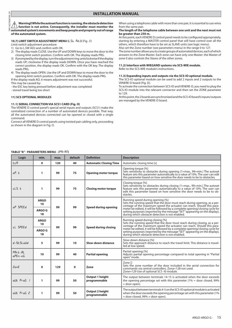
Warning!! While the autoset function is running, the obstacle detection function is not active. Consequently, the installer must monitor the
automated system’s movements and keep people and property out of range of the automated system.
10.7) LIMIT SWITCH ADJUSTMENT MENU (L.SW ADJ) (Fig . E)Limit switch adjustment procedure:1) Go to L.SW ADJ and con&rm with OK.2) The display reads CLOSE. Use the UP and DOWN keys to move the door to the
closing limit switch position. Con&rm with OK. The display reads PRG.3) If prompted by the display, turn the adjustment ring: anticlockwise if the display
reads UP; clockwise if the display reads DOWN. Once you have reached the correct position, the display reads OK. Con&rm with the OK key. The display reads PRG.
4) The display reads OPEN. Use the UP and DOWN keys to move the door to the opening limit switch position. Con&rm with OK. The display reads PRG.
If the display reads KO, it means adjustment was not successful.This may be caused by:- the ESC key being pressed before adjustment was completed- stored travel being too short
11) SCS OPTIONAL MODULES
11.1) SERIAL CONNECTION VIA SCS1 CARD (Fig. O) The VENERE D control panel’s special serial inputs and outputs (SCS1) make the centralized connection of a number of automated devices possible. That way, all the automated devices connected can be opened or closed with a single command. Connect all VENERE D control panels using twisted pair cabling only, proceeding as shown in the diagram in Fig. O.
When using a telephone cable with more than one pair, it is essential to use wires from the same pair. The length of the telephone cable between one unit and the next must not be greater than 250 m. At this point, each VENERE D control panel needs to be con&gured appropriately, starting by entering a MASTER control panel that will have control over all the others, which therefore have to be set as SLAVE units (see logic menu). Also set the Zone number (see parameters menu) in the range 0 to 127. The zone number allows you to create groups of automated devices, each of which answers to the Zone Master. Each zone can have only one Master: the Master of zone 0 also controls the Slaves of the other zones.
11.2) Interface with WIEGAND systems via SCS-WIE module.Refer to the SCS-WIE module’s instructions.
11.3) Expanding inputs and outputs via the SCS-IO optional module.The SCS-IO optional module can be used to add 2 inputs and 2 outputs to the VENERE-D board (Fig. D).To activate the connection between SCS-IO and VENERE-D, you need to plug the SCS-IO module into the relevant connector and then set the ZONE parameter to 129.At this point, the 2 boards are synchronized and the SCS-IO board’s inputs/outputs are managed by the VENERE-D board.
TABLE “A” - PARAMETERS MENU - (PARAM)
Logic min. max. default De%nition Description
tca 0 120 40 Automatic Closing Time Automatic closing time [s]
op. t 1 99 75 Opening motor torque
Opening torque [%]Sets sensitivity to obstacles during opening (1=max., 99=min.) The autoset feature sets this parameter automatically to a value of 10%. The user can edit this parameter based on how sensitive the door needs to be to obstacles.
cls. t 1 99 75 Closing motor torque
Closing torque [%]Sets sensitivity to obstacles during closing (1=max., 99=min.) The autoset feature sets this parameter automatically to a value of 10%. The user can edit this parameter based on how sensitive the door needs to be to ob-stacles.
op speed
ARGO10
99 99 Speed during opening
Running speed during opening [%]Sets the running speed that the door must reach during opening, as a per-centage of the maximum speed the actuator can reach. Should this para-meter be edited, it will be followed by a complete opening/closing cycle for setting purposes (reported by the message “SET” appearing on the display), during which obstacle detection is not enabled.
ARGO G18
cl speed
ARGO10
99 99 Speed during closing
Running speed during closing [%]Sets the running speed that the door must reach during closing, as a per-centage of the maximum speed the actuator can reach. Should this para-meter be edited, it will be followed by a complete opening/closing cycle for setting purposes (reported by the message “SET” appearing on the display), during which obstacle detection is not enabled.
ARGO G18
dist.sloud 5 99 10 Slow-down distanceSlow-down distance [%]Sets the approach distance to reach the travel limit. This distance is travel-led at low speed.
partial
opening10 99 40 Partial opening
Partial opening [%]Adjusts partial opening percentage compared to total opening in “Partial open” mode.
zone 0 129 0 Zone
Zone []Sets the zone number of the door included in the serial connection for commands via central controllers. Zona=128 not used.Zone=129 Use of optional SCS -I0 module.
out prog 1 1 99 50Output 1 heightprogrammable
The output between terminals 14-15 is activated when the door exceeds the opening percentage set with this parameter (1% = door closed, 99% = door open).
out prog 2 1 99 50Output 2 heightprogrammable
The output between terminals 4-5 on the SCS-IO optional module is activated when the door exceeds the opening percentage set with this parameter (1% = door closed, 99% = door open).
ARGO-ARGO G - 15
D81
1627
A00
100_
03
INSTALLATION MANUAL
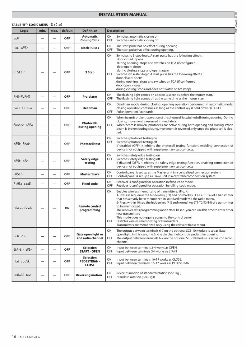
TABLE “B” - LOGIC MENU - (logic)
Logic min. max. default De%nition Description
tca --- --- OFFAutomatic
Closing TimeON Switches automatic closing onOFF Switches automatic closing o!
ibl. open --- --- OFF Block PulsesON The start pulse has no e!ect during opening.OFF The start pulse has e!ect during opening.
3 step --- --- OFF 3 Step
ON Switches to 3-step logic. A start pulse has the following e!ects: door closed: opens during opening: stops and switches on TCA (if con&gured). door open: closes during closing: stops and opens againOFF Switches to 4-step logic. A start pulse has the following e!ects: door closed: opens during opening: stops and switches on TCA (if con&gured) door open: closes during closing: stops and does not switch on tca (stop)
pre-alar --- --- OFF Pre-alarmON The $ashing light comes on approx. 3 seconds before the motors start.OFF The $ashing light comes on at the same time as the motors start
hold-to-run --- --- OFF DeadmanON Deadman mode during closing: opening operation performed in automatic mode;
closing operation continues as long as the control key is held down. (CLOSE).OFF Pulse operation (standard)
photoc. open --- --- OFFPhotocells
during opening
ON: When beam is broken, operation of the photocell is switched o! during opening. During closing, movement is reversed immediately.
OFF: When beam is broken, photocells are active during both opening and closing. When beam is broken during closing, movement is reversed only once the photocell is clea-red.
test phot --- --- OFF Photocell test
ON Switches photocell testing onOFF Switches photocell testing o! If disabled (OFF), it inhibits the photocell testing function, enabling connection of
devices not equipped with supplementary test contacts.
test bar --- --- OFFSafety edge
testing
ON Switches safety edge testing onOFF Switches safety edge testing o! If disabled (OFF), it inhibits the safety edge testing function, enabling connection of
devices not equipped with supplementary test contacts
aster --- --- OFF Master/SlaveON Control panel is set up as the Master unit in a centralized connection system. OFF Control panel is set up as a Slave unit in a centralized connection system.
fixed code --- --- OFF Fixed codeON Receiver is con&gured for operation in &xed-code mode.OFF Receiver is con&gured for operation in rolling-code mode.
radio prog --- --- ONRemote control programming
ON Enables wireless memorizing of transmitters: (Fig. K) 1- Press in sequence the hidden key (P1) and normal key (T1-T2-T3-T4) of a transmitter
that has already been memorized in standard mode via the radio menu. 2- Press within 10 sec. the hidden key (P1) and normal key (T1-T2-T3-T4) of a transmitter
to be memorized. The receiver exits programming mode after 10 sec.: you can use this time to enter other
new transmitters. This mode does not require access to the control panel.OFF Disables wireless memorizing of transmitters. Transmitters are memorized only using the relevant Radio menu.
sca-2ch --- --- OFFGate open light or 2nd radio channel
ON The output between terminals 6-7 on the optional SCS-10 module is set as Gate open light: in this case, the 2nd radio channel controls pedestrian opening.
OFF The output between terminals 6-7 on the optional SCS-10 module is set as 2nd radio channel
start - open --- --- OFFSelection
START - OPENON Input between terminals 3-4 works as OPEN.OFF Input between terminals 3-4 works as START
ped-close --- --- OFFSelection
PEDESTRIAN - CLOSE
ON Input between terminals 16-17 works as CLOSE.OFF Input between terminals 16-17 works as PEDESTRIAN
change ot. --- --- OFF Reversing motionON Reverses motion of standard rotation (See Fig.I). OFF Standard rotation (See Fig.I).
16 - ARGO-ARGO G
D81
1627
A00
100_
03
CA B
Rosso-Red-Rouge-Rot-Rojo-Rood
Verde - Green-Vert-Grün-Verde-Groen
ARGO G
ARGO
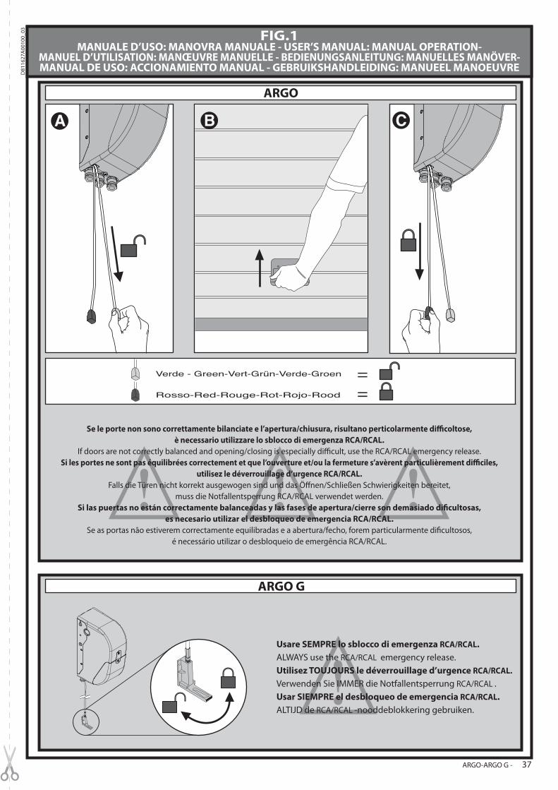
FIG.1MANUALE D’USO: MANOVRA MANUALE - USER’S MANUAL: MANUAL OPERATION-
MANUEL D’UTILISATION: MANŒUVRE MANUELLE - BEDIENUNGSANLEITUNG: MANUELLES MANÖVER-MANUAL DE USO: ACCIONAMIENTO MANUAL - GEBRUIKSHANDLEIDING: MANUEEL MANOEUVRE
Se le porte non sono correttamente bilanciate e l’apertura/chiusura, risultano perticolarmente di*coltose,è necessario utilizzare lo sblocco di emergenza RCA/RCAL.
If doors are not correctly balanced and opening/closing is especially di@cult, use the RCA/RCAL emergency release. Si les portes ne sont pas équilibrées correctement et que l’ouverture et/ou la fermeture s’avèrent particulièrement di*ciles,
utilisez le déverrouillage d’urgence RCA/RCAL. Falls die Türen nicht korrekt ausgewogen sind und das Ö!nen/Schließen Schwierigkeiten bereitet,
muss die Notfallentsperrung RCA/RCAL verwendet werden. Si las puertas no están correctamente balanceadas y las fases de apertura/cierre son demasiado di%cultosas,
es necesario utilizar el desbloqueo de emergencia RCA/RCAL.Se as portas não estiverem correctamente equilibradas e a abertura/fecho, forem particularmente di&cultosos,
é necessário utilizar o desbloqueio de emergência RCA/RCAL.
Usare SEMPRE lo sblocco di emergenza RCA/RCAL.
ALWAYS use the RCA/RCAL emergency release.
Utilisez TOUJOURS le déverrouillage d’urgence RCA/RCAL.
Verwenden Sie IMMER die Notfallentsperrung RCA/RCAL .
Usar SIEMPRE el desbloqueo de emergencia RCA/RCAL.
ALTIJD de RCA/RCAL -nooddeblokkering gebruiken.
ARGO-ARGO G - 37
D81
1627
A00
100_
03
AVVERTENZE PER L’UTILIZZATORE ( I )ATTENZIONE! Importanti istruzioni di sicurezza. Leggere e seguire attentamente le Avvertenze e le Istruzioni che accompagnano il prodotto poiché un uso improprio può causare danni a persone, animali o cose. Conservare le istruzioni per consultazioni future e trasmetterle ad eventuali subentranti nell’uso dell’impianto.Questo prodotto dovrà essere destinato solo all’uso per il quale è stato espressamente installato. Ogni altro uso è da considerarsi improprio e quindi pericoloso. Il costruttore non può essere considerato responsabile per eventuali danni causati da usi impropri, erronei e irragionevoli.
SICUREZZA GENERALENel ringraziarVi per la preferenza accordata a questo prodotto, la Ditta è certa che da esso otterrete le prestazioni necessarie al Vostro uso.Questo prodotto risponde alle norme riconosciute della tecnica e della disposizioni relative alla sicurezza se correttamente installato da personale quali&cato ed esperto (installatore professionale).L’automazione, se installata ed utilizzata correttamente, soddisfa gli standard di sicurezza nell’uso. Tuttavia è opportuno osservare alcune regole di comportamento per evitare inconvenienti accidentali:- Tenere bambini, persone e cose fuori dal raggio d’azione dell’automazione, in particolare durante il movimento.
- Non permettere a bambini di giocare o sostare nel raggio di azione dell’automazione.- Questa automazione non è destinata all’uso da parte di bambini o da parte di persone con ridotte
capacità mentali, &siche e sensoriali, o persone che mancano di conoscenze adeguate.- Evitare di operare in prossimità delle cerniere o organi meccanici in movimento.- Non contrastare il movimento dell’anta e non tentare di aprire manualmente la porta se non è stato sbloccato l’attuatore con l’apposita manopola di sblocco.
- Non entrare nel raggio di azione della porta o cancello motorizzati durante il loro movimen-to.
- Non lasciare radiocomandi o altri dispositivi di comando alla portata dei bambini onde evitare azionamenti involontari.
- L’attivazione dello sblocco manuale potrebbe causare movimenti incontrollati della porta se in presenza di guasti meccanici o di condizioni di squilibrio.
- In caso di apritapparelle: sorvegliare la tapparella in movimento e tenere lontano le persone &nché non è completamente chiusa. Porre cura quando si aziona lo sblocco se presente, poiché una tapparella aperta potrebbe cadere rapidamente in presenza di usura o rottu-re.
- La rottura o l’usura di organi meccanici della porta (parte guidata), quali ad esempio cavi, molle, supporti, cardini, guide.. potrebbe generare pericoli. Far controllare periodicamente l’impianto da personale quali&cato ed esperto (installatore professionale) secondo quanto indicato dall’installatore o dal costruttore della porta.
- Per ogni operazione di pulizia esterna, togliere l’alimentazione di rete.- Tenere pulite le ottiche delle fotocellule ed i dispositivi di segnalazione luminosa. Controllare che rami ed arbusti non disturbino i dispositivi di sicurezza.
- Non utilizzare l’automatismo se necessita di interventi di riparazione. In caso di guasto o di malfunzionamento dell’automazione, togliere l’alimentazione di rete sull’automazione, astenersi da qualsiasi tentativo di riparazione o intervento diretto e rivolgersi solo a per-sonale quali&cato ed esperto (installatore professionale) per la necessaria riparazione o manutenzione. Per consentire l’accesso, attivare lo sblocco di emergenza (se presente).
- Per qualsiasi intervento diretto sull’automazione o sull’impianto non previsto dal presente manuale, avvalersi di personale quali&cato ed esperto (installatore professionale).
- Con frequenza almeno annuale far veri&care l’integrità e il corretto funzionamento dell’automazione da personale quali&cato ed esperto (installatore professionale), in parti-colare di tutti i dispositivi di sicurezza.
- Gli interventi d’installazione, manutenzione e riparazione devono essere documentati e la relativa documentazione tenuta a disposizione dell’utilizzatore.
- Il mancato rispetto di quanto sopra può creare situazioni di pericolo.Tutto quello che non è espressamente previsto nel manuale d’uso, non è permesso. ll buon funzionamento dell’operatore è garantito solo se vengono rispettate le prescrizioni riportate in questo manuale. La Ditta non risponde dei danni causati dall’inosservanza delle indicazioni riportate in questo manuale.Lasciando inalterate le caratteristiche essenziali del prodotto, la Ditta si riserva di appor-tare in qualunque momento le modi%che che essa ritiene convenienti per migliorare tecnicamente, costruttivamente e commercialmente il prodotto, senza impegnarsi ad aggiornare la presente pubblicazione.
USER WARNINGS (GB)WARNING! Important safety instructions. Carefully read and comply with the Warnings and Instructions that come with the product as improper use can cause injury to people and animals and damage to property. Keep the instructions for future reference and hand them on to any new users.This product is meant to be used only for the purpose for which it was explicitly ins-talled. Any other use constitutes improper use and, consequently, is hazardous. The manufacturer cannot be held liable for any damage as a result of improper, incorrect or unreasonable use.
GENERAL SAFETYThank you for choosing this product. The Firm is con&dent that its performance will meet your operating needs.This product meets recognized technical standards and complies with safety provisions when installed correctly by quali&ed, expert personnel (professional installer).If installed and used correctly, the automated system will meet operating safety standards. Nonetheless, it is advisable to observe certain rules of behaviour so that accidental problems can be avoided:- Keep adults, children and property out of range of the automated system, especially while it is moving.
- Do not allow children to play or stand within range of the automated system.- This automated system is not meant for use by children or by people with impaired mental, physical or sensory capacities, or people who do not have suitable knowledge.
- Do not work near hinges or moving mechanical parts.- Do not hinder the leaf’s movement and do not attempt to open the door manually unless the actuator has been released with the relevant release knob.
- Keep out of range of the motorized door or gate while they are moving.- Keep remote controls or other control devices out of reach of children in order to avoid the automated system being operated inadvertently.
- The manual release’s activation could result in uncontrolled door movements if there are mechanical faults or loss of balance.
- When using roller shutter openers: keep an eye on the roller shutter while it is moving and keep people away until it has closed completely. Exercise care when activating the release, if such a device is &tted, as an open shutter could drop quickly in the event of wear or breakage.
- The breakage or wear of any mechanical parts of the door (operated part), such as cables,
quali&ed, expert personnel (professional installer) at regular intervals according to the instructions issued by the installer or manufacturer of the door.
- When cleaning the outside, always cut o! mains power.- Keep the photocells’ optics and illuminating indicator devices clean. Check that no branches or shrubs interfere with the safety devices.
- Do not use the automated system if it is in need of repair. In the event the automated system
breaks down or malfunctions, cut o! mains power to the system; do not attempt to repair or perform any other work to rectify the fault yourself and instead call in quali&ed, expert personnel (professional installer) to perform the necessary repairs or maintenance. To allow access, activate the emergency release (where &tted).
- If any part of the automated system requires direct work of any kind that is not contemplated herein, employ the services of quali&ed, expert personnel (professional installer).
- At least once a year, have the automated system, and especially all safety devices, checked by quali&ed, expert personnel (professional installer) to make sure that it is undamaged and working properly.
- A record must be made of any installation, maintenance and repair work and the relevant documentation kept and made available to the user on request.
- Failure to comply with the above may result in hazardous situations.
Anything that is not explicitly provided for in the user guide is not allowed. The operator’s proper operation can only be guaranteed if the instructions given herein are complied with. The Firm shall not be answerable for damage caused by failure to comply with the instructions featured herein.While we will not alter the product’s essential features, the Firm reserves the right, at any time, to make those changes deemed opportune to improve the product from a technical, design or commercial point of view, and will not be required to update this publication accordingly.
AVERTISSEMENTS POUR L’UTILISATEUR (F)ATTENTION ! Instructions de sécurité importantes. Veuillez lire et suivre attentivement tous les avertissements et toutes les instructions fournis avec le produit sachant qu’un usage incorrect peut provoquer des préjudices aux personnes, aux animaux ou aux biens. Veuillez conserver les instructions pour d’ultérieures consultations et pour les transmettre aux propriétaires futurs éventuels. Cet appareil ne peut être destiné qu’à l’usage pour lequel il a été expressément installé. Tout autre usage sera considéré comme impropre et donc dangereux. Le fabricant ne sera en aucun cas considéré comme responsable des préjudices dus à un usage impropre, erroné ou déraisonné.
SECURITE GÉNÉRALENous vous remercions d’avoir choisi ce produit qui, nous n’en doutons pas, saura vous garantir les performances attendues.Ce produit, correctement installé par du personnel quali&é et expérimenté (monteur professionnel) est conforme aux normes reconnues de la technique et des prescriptions de sécurité.Si l’automatisation est montée et utilisée correctement, elle garantit la sécurité d’utilisation prescrite. Il est cependant nécessaire de respecter certaines règles de comportement pour éviter tout inconvénient accidentel.- Tenir les enfants, les personnes et les objets à l’écart du rayon d’action de l’automatisation, en particulier pendant son fonctionnement.
- Empêcher les enfants de jouer ou de stationner dans le rayon d’action de l’automatisation.
- Cette automatisation n’est pas conçue pour être utilisée par des enfants, des personnes ayant un handicap mental, physique ou sensoriel ou des personnes dépourvues des connaissances nécessaires.
- Eviter d’opérer à proximité des charnières ou des organes mécaniques en mouvement.- Ne pas s’opposer volontairement au mouvement du vantail et ne pas tenter d’ouvrir la porte à la main si le déclencheur n’est pas déverrouillé avec le levier de déverrouillage prévu à cet e!et.
- Ne pas entrer dans le rayon d’action du portail/de la porte motorisé/e pendant son mouve-ment.
- Ranger les radiocommandes ou les autres dispositifs de commande hors de portée des enfants a&n d’éviter tout actionnement involontaire.
- L’activation du déverrouillage manuel risque de provoquer des mouvements incontrôlés de la porte en présence de pannes mécaniques ou de conditions de déséquilibre.
- Avec les ouvre-stores: surveiller le store en mouvement et veiller à ce que les personnes restent à l’écart tant qu’il n’est pas complètement fermé. Actionner l’éventuel déverrouillage avec prudence car si un store reste ouvert il peut tomber brutalement s’il est usé ou cassé.
- La rupture ou l’usure des organes mécaniques de la porte (partie guidée), tels que les câbles, les ressorts, les supports et les gonds peuvent générer des risques. Faire contrôler périodi-quement l’installation par du personnel quali&é et expérimenté (monteur professionnel), conformément aux indications du monteur ou du fabricant de la porte.
- Mettre hors tension avant d’accomplir les opérations de nettoyage extérieur.- Veiller à la propreté des lentilles des photocellules et des lampes de signalisation. Veiller à ce que les dispositifs de sécurité ne soient pas gênés par des branches ou des arbustes.
- Ne pas utiliser l’automatisation si elle a besoin d’être réparée. En cas de panne ou de mauvais fonctionnement de l’automatisation, mettre l’automatisation hors tension, éviter toute tentative de réparation ou d’intervention directe et s’adresser uniquement à du personnel quali&é et expérimenté (monteur professionnel) pour la réparation ou les opérations d’entretien nécessaires. Pour permettre l’accès, activer le déverrouillage d’urgence (s’il y en a un).
- Pour toutes les interventions directes sur l’automatisation ou sur l’installation non prévues dans le présent manuel, s’adresser uniquement à du personnel quali&é et expérimenté (monteur professionnel).
- Une fois par an au moins, faire véri&er le bon état et le bon fonctionnement de l’automatisation par du personnel quali&é et expérimenté (monteur professionnel) et en particulier tous les dispositifs de sécurité.
- Les interventions de montage, d’entretien et de réparation doivent être documentées et cette documentation doit être tenue à la disposition de l’utilisateur.
- Le non respect des prescriptions ci-dessus peut être à l’origine de dangers.
Tout ce qui n’est pas expressément prévu dans le manuel de montage est interdit. Le bon fonctionnement de l’appareil n’est garanti que si les données indiquées sont respectées. Le Fabricant ne répond pas des dommages provoqués par l’inobservation des indications données dans ce manuel.En laissant inaltérées les caractéristiques essentielles de l’appareil, l’entreprise se réserve le droit d’apporter à tout moment les modi%cations qu’elle jugera opportunes pour améliorer le produit du point de vue technique, commercial et de sa construction, sans s’engager à mettre à jour la présente publication.
HINWEISE FÜR DEN BENUTZER (D)ACHTUNG! Wichtige Hinweise zur Sicherheit. Bitte lesen und befolgen Sie aufmerksam die Hinweise sowie die Bedienungsanleitung, die das Produkt begleiten, denn eine falsche Benutzung des Produkts kann zu Verletzungen von Menschen und Tieren sowie zu Sachschäden führen. Bitte bewahren Sie die Anweisungen für die zukünftige Konsultation sowie für eventuelle zukünftige Benutzer der Anlage auf.Dieses Produkt ist ausschließlich für den Einsatz bestimmt, für den es ausdrücklich installiert worden ist. Alle sonstigen Einsatzweisen gelten als Zweckentfremdung und somit als gefährlich. Der Hersteller kann nicht für eventuelle Schäden haftbar gemacht werden, die auf Zweckentfremdung oder unsachgemäße Verwendung zurückzuführen sind.
ALLGEMEINE SICHERHEITWir danken Ihnen dafür, dass Sie diesem Produkt den Vorzug gegeben haben, und sind sicher,
38 - ARGO-ARGO G
D81
1627
A00
100_
03