areca mgmt
DESCRIPTION
ManualTRANSCRIPT
ARC-1110/1120/1130/1160/1170
( 4/8/12/16/24-port PCI-X SATA RAID Controllers )
ARC-1110ML/1120ML/1130ML/1160ML
( 4/8/12/16-port PCI-X SATA RAID Controllers )
ARC-1210/1220/1230/1260
( 4/8/12/16-port PCI-Express SATA RAID Controllers )
SATA RAID Cards
Copyright StatementAreca Technology Corporation© COPYRIGHT 2005
ALL RIGHTS RESERVED. First Edition. All trademarks are the properties of their respective owners. No por-tion of this document may be reproduced, altered, adapted or trans-lated without the prior written approval.
USER ManualVersion: 2.10Issue Date: May, 2005
Microsoft WHQL Windows Hardware Compatibility Test
ARECA is committed to submit to Microsoft Windows Hardware Quality Labs (WHQL) for participation in the Windows Logo Program. Successful passage of the WHQL tests results in both the “Designed for Windows” logo for qualifying ARECA PCI-X or PCI-Express SATA RAID controllers and a listing on the Microsoft Hardware Compatibility List (HCL).
WARRANTY
The information in this document is subject to change without notice. We make no warranty of any kind regarding this material, including, but not limited to, the implied warranties or merchantability and fitness for a particular purpose. Furthermore, we shall not be liable for errors con-tained herein or for incidental or consequential damage in connection with the furnishing, performance, or use of this material.
FCC STATEMENT
This equipment has been tested and found to comply with the limits for a Class B digital device, pursuant to part 15 of the FCC Rules. These limits are designed to provide reasonable protection against interfer-ence in a residential installation. This equipment generates, uses, and can radiate radio frequency energy and, if not installed and used in ac-cordance with the instructions, may cause harmful interference to radio communications. However, there is no guarantee that interference will not occur in a particular installation.
Contents1. Introduction ................................................................ 8
1.1 Overview .........................................................................81.2 Features ........................................................................ 101.3 RAID Concept ................................................................. 12
1.3.1 RAID Set ................................................................... 121.3.2 Volume Set ................................................................ 121.3.3 Easy of Use Features ................................................. 13
1.3.3.1 Instant Availability/Background Initialization ............ 131.3.3.2 Array Roaming ..................................................... 131.3.3.3 Online Capacity Expansion ..................................... 14
1.3.4 Online RAID Level and Stripe Size Migration .................. 151.4 High availability .............................................................. 15
1.4.1 Creating Hot Spares ................................................... 151.4.2 Hot-Swap Disk Drive Support ....................................... 161.4.3 Hot-Swap Disk Rebuild ................................................ 16
1.5 Understanding RAID ........................................................ 161.5.1 RAID 0 ...................................................................... 171.5.2 RAID 1 ...................................................................... 171.5.3 RAID 10 .................................................................... 181.5.4 RAID 3 ...................................................................... 181.5.5 RAID 5 ...................................................................... 191.5.6 RAID 6 ...................................................................... 19
2. Hardware Installation ............................................... 222.1 Before Your begin Installation ........................................... 222.2 Board Layout .................................................................. 232.3 Installation ..................................................................... 27
3. McBIOS RAID Manager .............................................. 383.1 Starting the McBIOS RAID Manager ................................... 383.2 McBIOS Configuration manager ......................................... 393.3 Configuring Raid Sets and Volume Sets .............................. 403.4 Designating Drives as Hot Spares ...................................... 403.5 Using Quick Volume /Raid Setup Configuration .................... 413.6 Using Raid Set/Volume Set Function Method ....................... 423.7 Main Menu .................................................................... 44
3.7.1 Quick Volume/RAID Setup ........................................... 453.7.2 Raid Set Function ....................................................... 47
3.7.2.1 Create Raid Set .................................................... 48

3.7.2.2 Delete Raid Set ..................................................... 493.7.2.3 Expand Raid Set .................................................... 49• Migrating ...................................................................... 503.7.2.4 Activate Incomplete Raid Set ................................... 513.7.2.5 Create Hot Spare ................................................... 523.7.2.6 Delete Hot Spare ................................................... 523.7.2.7 Raid Set Information .............................................. 53
3.7.3 Volume Set Function ................................................... 533.7.3.1 Create Volume Set ................................................. 54• Volume Name ................................................................ 56• Raid Level ..................................................................... 56• Capacity ....................................................................... 57• Strip Size ...................................................................... 57• SCSI Channel ................................................................ 58• SCSI ID ........................................................................ 58• SCSI LUN ...................................................................... 59• Cache Mode .................................................................. 59• Tag Queuing .................................................................. 593.7.3.2 Delete Volume Set ................................................. 603.7.3.3 Modify Volume Set ................................................. 61• Volume Growth .............................................................. 62• Volume Set Migration ...................................................... 623.7.3.4 Check Volume Set .................................................. 633.7.3.5 Stop Volume Set Check .......................................... 633.7.3.6 Display Volume Set Info. ........................................ 64
3.7.4 Physical Drives ........................................................... 653.7.4.1 View Drive Information .......................................... 653.7.4.2 Create Pass-Through Disk ....................................... 663.7.4.3 Modify Pass-Through Disk ....................................... 663.7.4.4 Delete Pass-Through Disk ....................................... 673.7.4.5 Identify Selected Drive ........................................... 67
3.7.5 Raid System Function ................................................. 683.7.5.1 Mute The Alert Beeper ........................................... 683.7.5.2 Alert Beeper Setting ............................................... 693.7.5.3 Change Password .................................................. 693.7.5.4 JBOD/RAID Function .............................................. 703.7.5.5 Background Task Priority ........................................ 713.7.5.6 Maximum SATA Mode ............................................. 713.7.5.7 Disk Write Cache Mode ........................................... 723.7.5.8 Capacity Truncation ............................................... 723.7.5.9 Controller Fan Detection ......................................... 733.7.5.10 HDD SMART Status Polling .................................... 74
3.7.6 Ethernet Configuration (12/16/24 ports) ........................ 743.7.6.1 DHCP Function ...................................................... 753.7.6.2 Local IP address .................................................... 753.7.6.3 Ethernet Address ................................................... 76
3.7.7 View System Events ................................................... 773.7.8 Clear Events Buffer ..................................................... 773.7.9 Hardware Monitor ....................................................... 773.7.10 System Information .................................................. 78
4. Driver Installation ..................................................... 794.1 Creating the Driver Diskettes ............................................ 794.2 Driver Installation for Windows ......................................... 80
4.2.1 New Storage Device Drivers in Windows Server 2003 ...... 804.2.2 Install Windows 2000/XP/2003 on a SATA RAID Volume .. 81
4.2.2.1 Installation procedures ........................................... 814.2.2.2 Making Volume Sets Available to Windows System ..... 82
4.2.3 Install controller into an existing Windows 2000/XP/2003 834.2.3.1 Making Volume Sets Available to Windows System ..... 84
4.2.4 Uninstall controller from Windows 2000/XP/2003 ............ 854.3 Driver Installation for Linux .............................................. 864.4 Driver Installation for FreeBSD .......................................... 86
5. Installation ArcHttp Proxy Server .............................. 885.1 For Windows .................................................................. 885.2 For Linux ....................................................................... 89
6. Web Browser-based Configuration ........................... 916.1 Start-up McRAID Manager for Local Administration .............. 91
6.1.1 For Windows .............................................................. 926.1.2 For Linux ................................................................... 94
6.2 Start-up McRAID Manager for Remote Administration ........... 946.2.1 Microsoft Windows System .......................................... 946.2.2 Linux System ............................................................. 95
6.3 SATA RAID controller McRAID storage manager ................... 956.4 Main Menu .................................................................... 966.5 Quick Function ................................................................ 976.6 RaidSet Functions ........................................................... 98
6.6.1 Create Raid Set ......................................................... 986.6.2 Delete Raid Set .......................................................... 986.6.3 Expand Raid Set ......................................................... 996.6.4 Activate Incomplete Raid Set ....................................... 996.6.5 Create Hot Spare ..................................................... 1006.6.6 Delete Hot Spare ...................................................... 1016.6.7 Rescue Raid Set ....................................................... 101
6.7 Volume Set Functions .................................................... 1016.7.1 Create Volume Set ................................................... 102
• Volume Name .............................................................. 102• Capacity ..................................................................... 102• Raid Level .................................................................. 102• Strip Size .................................................................... 103• Cache Mode ................................................................ 103• SCSI Channel/SCSI ID/SCSI Lun .................................... 103• Tag Queuing ................................................................ 103
6.7.2 Delete Volume Set .................................................... 1036.7.3 Modify Volume Set .................................................... 104
6.7.3.1 Volume Set Migration ........................................... 1056.7.4 Check Volume Set .................................................... 1056.7.5 Stop VolumeSet Check .............................................. 106
6.8 Physical Drive .............................................................. 1066.8.1 Create Pass-Through Disk .......................................... 1066.8.2 Modify Pass-Through Disk .......................................... 1076.8.3 Delete Pass-Through Disk .......................................... 1086.8.4 Identify Selected Drive .............................................. 108
6.9 System Controls ........................................................... 1096.9.1 System Config ......................................................... 109
• System Beeper Setting ................................................. 109• Background Task Priority ............................................... 109• JBOD/RAID Configuration .............................................. 109
6.9.2 Ethernet Configuration (12/16/24 ports) ...................... 1106.9.3 Alert by Mail Configuration (12/16/24 ports) ............... 1116.9.4 SNMP Configuration .................................................. 1126.9.5 View Events/Mute Beeper .......................................... 1136.9.6 Generate Test Event ................................................. 1136.9.7 Clear Events Buffer ................................................... 1136.9.8 Modify Password ...................................................... 1146.9.9 Update Firmware ..................................................... 115
6.10 Information ................................................................ 1156.10.1 RaidSet Hierarchy ................................................... 1156.10.2 System Information ................................................ 1156.10.3 Hardware Monitor ................................................... 116
Appendix A ................................................................. 117Upgrading Firmware Through McRAID Storage Manager ........... 117
Appendix B .................................................................. 119Battery Backup Module (BBM) .............................................. 119
BBM Components ........................................................... 119
BBM Specifications .......................................................... 119Installation .................................................................... 120Battery Backup Capacity .................................................. 120Operation ...................................................................... 120Changing the Battery Backup Module ................................ 121
Appendix C .................................................................. 122SNMP Operation & Definition ................................................ 122
Appendix D .................................................................. 125General Troubleshooting Tips ............................................... 125
Appendix E .................................................................. 129Technical Support ............................................................... 129
Glossary ...................................................................... 1302TB .............................................................................. 130Array ............................................................................ 130ATA .............................................................................. 130Auto Reassign Sector ..................................................... 130Battery Backup Module .................................................... 131BIOS ............................................................................ 131Cache ........................................................................... 131Consistency Check .......................................................... 131Driver ........................................................................... 131Hot Spare ...................................................................... 132Hardware RAID versus Software RAID .............................. 132Hot Swap ...................................................................... 132NVRAM .......................................................................... 132Parity ............................................................................ 132PCI Express .................................................................. 132PCI-X ........................................................................... 133RAID ............................................................................ 133Rebuild ......................................................................... 133SATA (Serial ATA) ........................................................... 133SMART .......................................................................... 134SNMP ............................................................................ 134Volume Set .................................................................... 134Write-back ..................................................................... 134Write-through ................................................................ 134XOR-Engine ................................................................... 135
INTRODUCTION
8
1. Introduction
This section briefly describes general overview of SATA RAID Series controller card, ARC-1110/1120/1130/1160/1170 (4/8/12/16/24-port PCI-X SATA RAID Controller) and ARC-1210/1220/1230/1260/1270 (4/8/12/16/24-port PCI-Express SATA RAID Controller).
1.1 Overview
ARC-11xx/12xx Series high-performance PCI bus Card Serial ATA RAID controller supported 4, 8, 12, 16, 24 SATA-II peripheral de-vice on a single controller. With properly configured, SATA controller can provided non-stop services with a high degree of fault tolerance through the use of RAID technology and advanced array manage-ment features. The 4/8 port SATA RAID controller is a low-profile PCI cards-Ideal for 1U or 2U rack-mount system. It has the same RAID kernel of its field-proven external RAID controller. Lets bring quickly to stable and reliable RAID controller to the market.
Unparalleled Performance
The array controllers provide reliable data protection for desktops, workstations and servers. They raise the standard higher perfor-mance levels with several enhancements including Intel high-perfor-mance I/O Processor, a new DDR memory architecture (DDR333) and high performance PCI bus interconnection. SATA RAID 8/12/16/24-port controller with Areca RAID 6 engine buid-in can offer extreme performance RAID 6 function. It can concurrently compute two par-ity blocks and performance very similar to RAID 5. The controllers default support 128MB ECC DDR333 SDRAM memory. The 12/16/24 ports controllers support one SODIMM socket for upgrading up to 1GB. The controllers use the Marvell 4/8 channels SATA PCI-X con-troller chip, which can simultaneously communicate with the host system, and read or write data on several drives.
Unsurpassed Data Availability
As storage capacities continue to rapidly increase, user needs greater level of disk drive fault tolerance, which can be implemented without
INTRODUCTION
9
doubling the investment in disk drives. RAID 1 can provide greater fault tolerance, but needs double disk drives and is too costly for most users to implement on large volume sets. User wants protec-tion of RAID 1 or better with an implementation cost comparable to RAID 5. The RAID 6 can offer fault tolerance greater that RAID 1 or RAID 5 but only consumes capacity of 2 disk drives for distributed parity data. The 8/12/16/24-port RAID controllers provide the high-est RAID 6 feature to meet above requirements.
The 4/8/12/16/24-port controllers also provide RAID levels 0, 1, (10), 3, 5, and JBOD RAID configurations. Its high data availability and protection derives from the following capabilities: Online RAID Capacity Expansion, Array Roaming, Online RAID Level / Stripe Size Migration, Dynamic Volume Set Expansion, Global Online Spare, Au-tomatic Drive Failure Detection, Automatic Failed Drive Rebuilding, Disk Hot-Swap, Online Background Rebuilding and Instant Availabil-ity/Background Initialization.
During the controller firmware upgrade flash process, it is possible for a problem to occur resulting in corruption of the controller firm-ware. With our Redundant Flash image feature the controller will revert back to the last known version of firmware and continue oper-ating. This reduces the risk of system failure due to firmware crash.
Easy RAID Management
SATA RAID controller build-in firmware with an embedded terminal emulation that can access via hot key at BIOS boot-up screen. This pre-boot manager utility can use to simplify the setup and manage-ment of RAID controller. The controller firmware also contains HTTP browser-based program that can access through the drive ArcHttp Proxy Server function in Windows, Linux and FreeBSD environment. The Web browser-based RAID management allows local and remote to create and modify RAID set, volume set, and monitor RAID status from standard web browser.
INTRODUCTION
10
1.2 Features
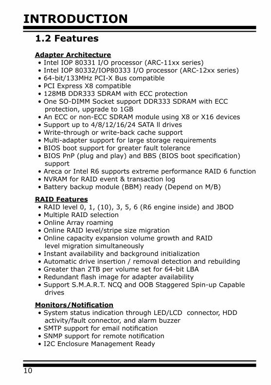
Adapter Architecture• Intel IOP 80331 I/O processor (ARC-11xx series)• Intel IOP 80332/IOP80333 I/O processor (ARC-12xx series)• 64-bit/133MHz PCI-X Bus compatible• PCI Express X8 compatible• 128MB DDR333 SDRAM with ECC protection• One SO-DIMM Socket support DDR333 SDRAM with ECC protection, upgrade to 1GB • An ECC or non-ECC SDRAM module using X8 or X16 devices• Support up to 4/8/12/16/24 SATA ll drives• Write-through or write-back cache support• Multi-adapter support for large storage requirements• BIOS boot support for greater fault tolerance• BIOS PnP (plug and play) and BBS (BIOS boot specification) support• Areca or Intel R6 supports extreme performance RAID 6 function• NVRAM for RAID event & transaction log• Battery backup module (BBM) ready (Depend on M/B)
RAID Features• RAID level 0, 1, (10), 3, 5, 6 (R6 engine inside) and JBOD• Multiple RAID selection• Online Array roaming• Online RAID level/stripe size migration• Online capacity expansion volume growth and RAID level migration simultaneously• Instant availability and background initialization• Automatic drive insertion / removal detection and rebuilding• Greater than 2TB per volume set for 64-bit LBA• Redundant flash image for adapter availability• Support S.M.A.R.T. NCQ and OOB Staggered Spin-up Capable drives
Monitors/Notification• System status indication through LED/LCD connector, HDD activity/fault connector, and alarm buzzer• SMTP support for email notification• SNMP support for remote notification• I2C Enclosure Management Ready
INTRODUCTION
11
RAID Management• Field-upgradeable firmware in flash ROM• Ethernet port support on 12/16/24-port
In-Band Manager• Hot key boot-up McBIOS RAID manager via BIOS• Support controller’s API library for customer to write its own AP• Support Command Line Interface (CLI)• Browser-based management utility via ArcHttp Proxy Server• Single Admin Portal (SAP) monitor utility• Disk Stress Test (DST) utility for production in Windows
Out-of-Band Manager• Firmware-embedded Browser-based RAID manager, SMTP manager, SNMP agent, and Telnet function via Ethernet port (for 12/16/24 port Adapter)• Support controller’s API library for customer to write its own AP(for 12/16/24 port Adapter)• Push Button and LCD display panel
Operating System• Windows 2000/XP/Server 2003• Red Hat Linux • SuSE Linux • FreeBSD
(For latest supported OS listing visit http://www.areca.com.tw)
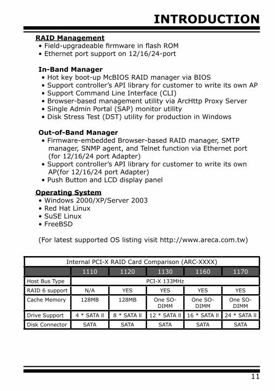
Internal PCI-X RAID Card Comparison (ARC-XXXX)
1110 1120 1130 1160 1170
Host Bus Type PCI-X 133MHz
RAID 6 support N/A YES YES YES YES
Cache Memory 128MB 128MB One SO-DIMM
One SO-DIMM
One SO-DIMM
Drive Support 4 * SATA ll 8 * SATA ll 12 * SATA ll 16 * SATA ll 24 * SATA ll
Disk Connector SATA SATA SATA SATA SATA
INTRODUCTION
12
1.3 RAID Concept
1.3.1 RAID Set
A Raid Set is a group of disk containing one or more volume sets. It has the following features in the SATA RAID controller. A volume Set must be created either on an existing raid set or on a group of available individual disks (disks that are not yet a part of an raid set). If there are pre-existing raid sets with available capacity and enough disks for specified RAID level desired, then the volume set will be created in the existing raid set of the user’s choice. If physical disk of different capacity are grouped together in a raid set, then the capacity of the smallest disk will become the effective capacity of all the disks in the raid set.
1.3.2 Volume Set
A Volume Set is seen by the host system as a single logical device. It is organized in a RAID level with one or more physical disks. RAID level refers to the level of data performance and protection of a Volume Set. A Volume Set capacity can consume all or a portion
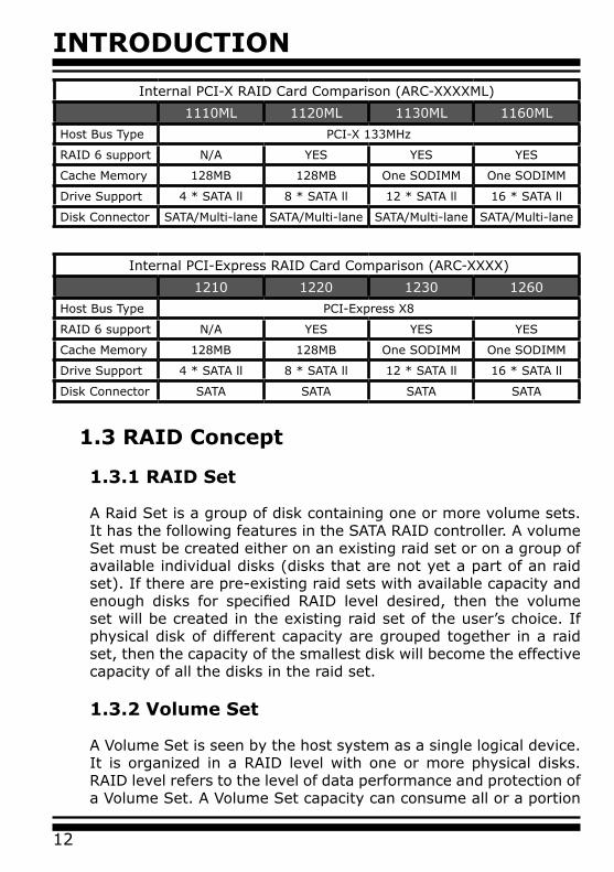
Internal PCI-Express RAID Card Comparison (ARC-XXXX)
1210 1220 1230 1260
Host Bus Type PCI-Express X8
RAID 6 support N/A YES YES YES
Cache Memory 128MB 128MB One SODIMM One SODIMM
Drive Support 4 * SATA ll 8 * SATA ll 12 * SATA ll 16 * SATA ll
Disk Connector SATA SATA SATA SATA
Internal PCI-X RAID Card Comparison (ARC-XXXXML)
1110ML 1120ML 1130ML 1160ML
Host Bus Type PCI-X 133MHz
RAID 6 support N/A YES YES YES
Cache Memory 128MB 128MB One SODIMM One SODIMM
Drive Support 4 * SATA ll 8 * SATA ll 12 * SATA ll 16 * SATA ll
Disk Connector SATA/Multi-lane SATA/Multi-lane SATA/Multi-lane SATA/Multi-lane
INTRODUCTION
13
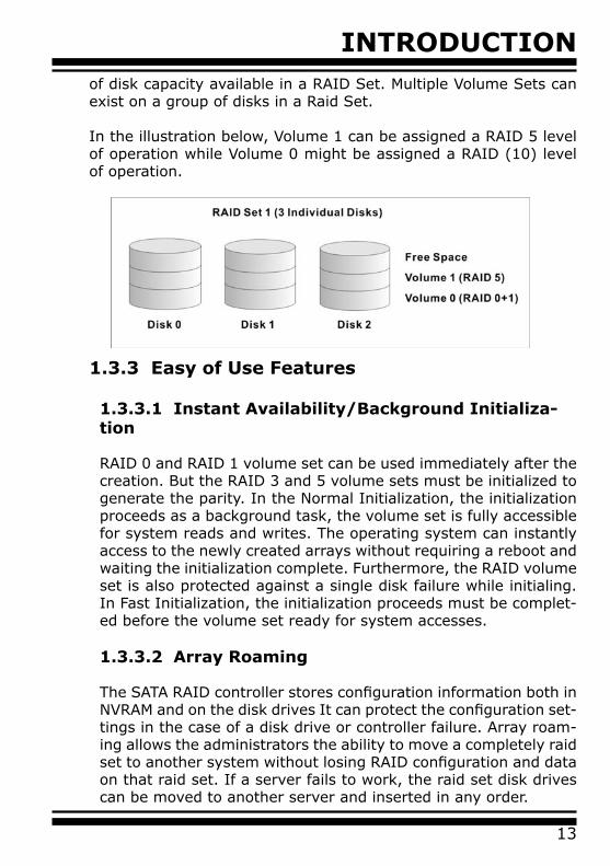
of disk capacity available in a RAID Set. Multiple Volume Sets can exist on a group of disks in a Raid Set.
In the illustration below, Volume 1 can be assigned a RAID 5 level of operation while Volume 0 might be assigned a RAID (10) level of operation.
1.3.3 Easy of Use Features
1.3.3.1 Instant Availability/Background Initializa-tion
RAID 0 and RAID 1 volume set can be used immediately after the creation. But the RAID 3 and 5 volume sets must be initialized to generate the parity. In the Normal Initialization, the initialization proceeds as a background task, the volume set is fully accessible for system reads and writes. The operating system can instantly access to the newly created arrays without requiring a reboot and waiting the initialization complete. Furthermore, the RAID volume set is also protected against a single disk failure while initialing. In Fast Initialization, the initialization proceeds must be complet-ed before the volume set ready for system accesses.
1.3.3.2 Array Roaming
The SATA RAID controller stores configuration information both in NVRAM and on the disk drives It can protect the configuration set-tings in the case of a disk drive or controller failure. Array roam-ing allows the administrators the ability to move a completely raid set to another system without losing RAID configuration and data on that raid set. If a server fails to work, the raid set disk drives can be moved to another server and inserted in any order.
INTRODUCTION
14
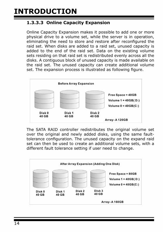
1.3.3.3 Online Capacity Expansion
Online Capacity Expansion makes it possible to add one or more physical drive to a volume set, while the server is in operation, eliminating the need to store and restore after reconfigured the raid set. When disks are added to a raid set, unused capacity is added to the end of the raid set. Data on the existing volume sets residing on that raid set is redistributed evenly across all the disks. A contiguous block of unused capacity is made available on the raid set. The unused capacity can create additional volume set. The expansion process is illustrated as following figure.
The SATA RAID controller redistributes the original volume set over the original and newly added disks, using the same fault-tolerance configuration. The unused capacity on the expand raid set can then be used to create an additional volume sets, with a different fault tolerance setting if user need to change.
INTRODUCTION
15
1.3.4 Online RAID Level and Stripe Size Migra-tion
User can migrate both the RAID level and stripe size of an existing volume set, while the server is online and the volume set is in use. Online RAID level/stripe size migration can prove helpful during performance tuning activities as well as in the event that additional physical disks are added to the SATA RAID controller. For example, in a system using two drives in RAID level 1, you could add capac-ity and retain fault tolerance by adding one drive. With the addi-tion of third disk, you have the option of adding this disk to your existing RAID logical drive and migrating from RAID level 1 to 5. The result would be parity fault tolerance and double the available capacity without taking the system off.
1.4 High availability
1.4.1 Creating Hot Spares
A hot spare drive is an unused online available drive, which is ready for replacing the failure disk drive. In a RAID level 1, (10), 3, or 5 raid set, any unused online available drive installed but not belong-ing to a raid set can define as a hot spare drive. Hot spares permit you to replace failed drives without powering down the system. When SATA RAID controller detects a SATA drive failure, the system will automatic and transparent rebuilds using hot spare drives. The raid set will be reconfigured and rebuilt in the background, while the SATA RAID controller continues to handle system request. Dur-ing the automatic rebuild process, system activity will continue as normal, however, the system performance and fault tolerance will be affected.
Important:
The hot spare must have at least the same capacity as the drive it replaces.

INTRODUCTION
16
1.4.2 Hot-Swap Disk Drive Support
The SATA RAID controller has built the protection circuit to sup-port the replacement of SATA hard disk drives without having to shut down or reboot the system. The removable hard drive tray can deliver “hot swappable,” fault-tolerant RAID solutions at prices much less than the cost of conventional SCSI hard disk SATA RAID controllers. We provide this feature for controllers to provide the advanced fault tolerant RAID protection and “online” drive replace-ment.
1.4.3 Hot-Swap Disk Rebuild
A Hot-Swap function can be used to rebuild disk drives in arrays with data redundancy such as RAID level 1, (10), 3, and 5. If a hot spare is not available, the failed disk drive must be replaced with a new disk drive so that the data on the failed drive can be rebuilt. If a hot spare is available, the rebuild starts automatically when a drive fails. The SATA RAID controller automatically and transpar-ently rebuilds failed drives in the background with user-definable rebuild rates. The SATA RAID controller will automatically restart the system and the rebuild if the system is shut down or powered off abnormally during a reconstruction procedure condition. When a disk is Hot Swap, although the system is functionally operational, the system may no longer be fault tolerant. Fault tolerance will be lost until the removed drive is replaced and the rebuild operation is completed.
1.5 Understanding RAID
RAID is an acronym for Redundant Array of Independent Disks. It is an array of multiple independent hard disk drives that provide high performance and fault tolerance. The SATA RAID controller imple-ments several levels of the Berkeley RAID technology. An appropri-ate RAID level is selected when the volume sets are defined or cre-ated. This decision is based on disk capacity, data availability (fault tolerance or redundancy), and disk performance. The following is the RAID level, which support in the SATA RAID controller.The SATA RAID controller makes the RAID implementation and the disks’ physical configuration transparent to the host operating sys-tem. This means that the host operating system drivers and software
INTRODUCTION
17
utilities are not affected, regardless of the RAID level selected. Cor-rect installation of the disk array and the controller requires a proper understanding of RAID technology and the concepts.
1.5.1 RAID 0
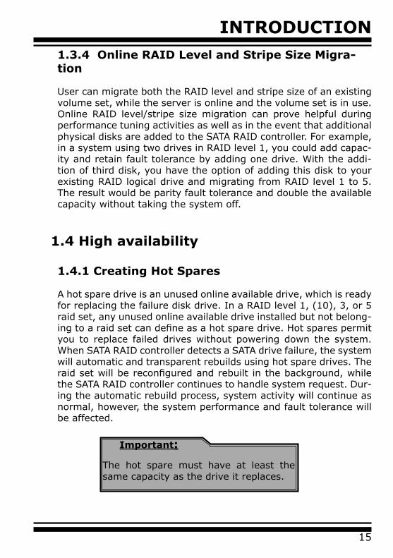
RAID 0, also referred to as striping, writes stripping of data across multiple disk drives instead of just one disk drive. RAID 0 does not provide any data redundancy, but does offer the best high-speed data throughput. RAID 0 breaks up data into smaller blocks and then writes a block to each drive in the array. Disk striping en-hances performance because multiple drives are accessed simul-taneously; but the reliability of RAID Level 0 is less than any of its member disk drives due to its lack of redundancy.
1.5.2 RAID 1
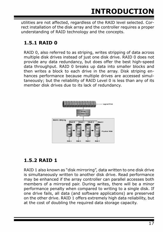
RAID 1 also known as “disk mirroring”, data written to one disk drive is simultaneously written to another disk drive. Read performance may be enhanced if the array controller can parallel accesses both members of a mirrored pair. During writes, there will be a minor performance penalty when compared to writing to a single disk. If one drive fails, all data (and software applications) are preserved on the other drive. RAID 1 offers extremely high data reliability, but at the cost of doubling the required data storage capacity.
INTRODUCTION
18
1.5.3 RAID 10
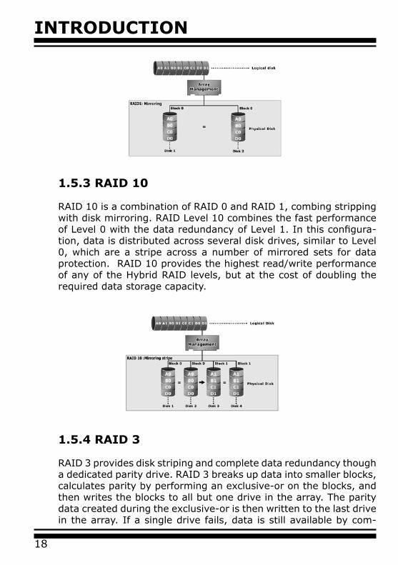
RAID 10 is a combination of RAID 0 and RAID 1, combing stripping with disk mirroring. RAID Level 10 combines the fast performance of Level 0 with the data redundancy of Level 1. In this configura-tion, data is distributed across several disk drives, similar to Level 0, which are a stripe across a number of mirrored sets for data protection. RAID 10 provides the highest read/write performance of any of the Hybrid RAID levels, but at the cost of doubling the required data storage capacity.
1.5.4 RAID 3
RAID 3 provides disk striping and complete data redundancy though a dedicated parity drive. RAID 3 breaks up data into smaller blocks, calculates parity by performing an exclusive-or on the blocks, and then writes the blocks to all but one drive in the array. The parity data created during the exclusive-or is then written to the last drive in the array. If a single drive fails, data is still available by com-
INTRODUCTION
19
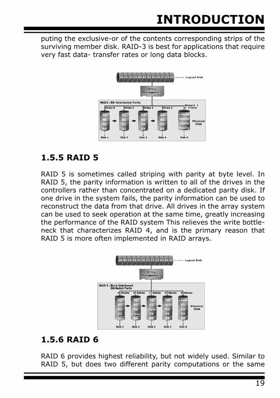
puting the exclusive-or of the contents corresponding strips of the surviving member disk. RAID-3 is best for applications that require very fast data- transfer rates or long data blocks.
1.5.5 RAID 5
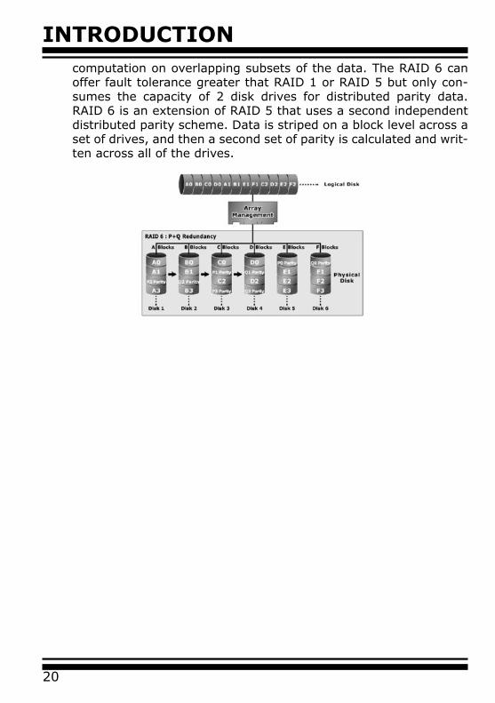
RAID 5 is sometimes called striping with parity at byte level. In RAID 5, the parity information is written to all of the drives in the controllers rather than concentrated on a dedicated parity disk. If one drive in the system fails, the parity information can be used to reconstruct the data from that drive. All drives in the array system can be used to seek operation at the same time, greatly increasing the performance of the RAID system This relieves the write bottle-neck that characterizes RAID 4, and is the primary reason that RAID 5 is more often implemented in RAID arrays.
1.5.6 RAID 6
RAID 6 provides highest reliability, but not widely used. Similar to RAID 5, but does two different parity computations or the same
INTRODUCTION
20
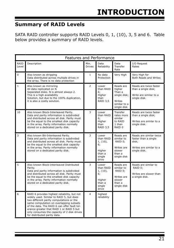
computation on overlapping subsets of the data. The RAID 6 can offer fault tolerance greater that RAID 1 or RAID 5 but only con-sumes the capacity of 2 disk drives for distributed parity data. RAID 6 is an extension of RAID 5 that uses a second independent distributed parity scheme. Data is striped on a block level across a set of drives, and then a second set of parity is calculated and writ-ten across all of the drives.
INTRODUCTION
21
Summary of RAID Levels
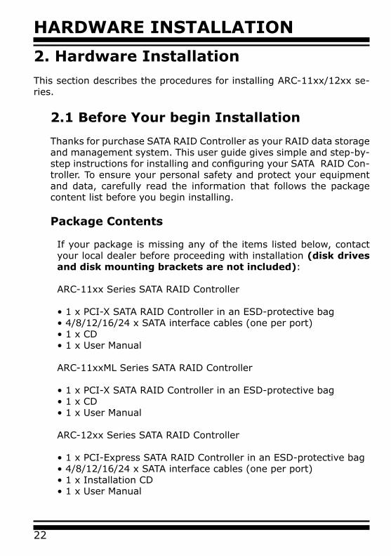
SATA RAID controller supports RAID Levels 0, 1, (10), 3, 5 and 6. Table below provides a summary of RAID levels.
Features and PerformanceRAIDLevel
Description Min. Drives
Data Reliability
Data Transfer Rate
I/O RequestRates
0 Also known as strippingData distributed across multiple drives in the array. There is no data protection
1 No dataProtection
Very High Very High forBoth Reads and Writes
1 Also known as mirroringAll data replicated on NSeparated disks. N is almost always 2.This is a high availabilitySolution, but due to the 100% duplication, it is also a costly solution.
2 Lower than RAID 6;Higher thanRAID 3,5
Reads are higherThan a single disk;
Writes similar to a single disk
Reads are twice faster than a single disk;
Write are similar to a single disk.
10 Also known Block-Interleaved Parity.Data and parity information is subdivided and distributed across all disk. Parity must be the equal to the smallest disk capacity in the array. Parity information normally stored on a dedicated parity disk.
3 Lower than RAID 6;Higher thanRAID 3,5
Transfer rates more similar to RAID 1 than RAID 0
Reads are twice faster than a single disk;
Writes are similar to a single disk.
3 Also known Bit-Interleaved Parity.Data and parity information is subdivided and distributed across all disk. Parity must be the equal to the smallest disk capacity in the array. Parity information normally stored on a dedicated parity disk.
3 Lower than RAID 1, (10), 6;
Higher than a single drive
Reads are similar to RAID 0;
Writes are slower than a single disk
Reads are similar twice faster than a single disk;
Writes are similar to a single disk.
5 Also known Block-Interleaved Distributed Parity.Data and parity information is subdivided and distributed across all disk. Parity must be the equal to the smallest disk capacity in the array. Parity information normally stored on a dedicated parity disk.
3 Lower than RAID 1, (10), 6;
Higher than a single drive
Reads are similar to RAID 0;
Writes are slower than a single disk
Reads are similar to RAID 0;
Writes are slower than a single disk.
6 RAID 6 provides highest reliability, but not widely used. Similar to RAID 5, but does two different parity computations or the same computation on overlapping subsets of the data. The RAID 6 can offer fault tol-erance greater that RAID 1 or RAID 5 but only consumes the capacity of 2 disk drives for distributed parity data.
4 highest reliability
HARDWARE INSTALLATION
22
2. Hardware InstallationThis section describes the procedures for installing ARC-11xx/12xx se-ries.
2.1 Before Your begin Installation
Thanks for purchase SATA RAID Controller as your RAID data storage and management system. This user guide gives simple and step-by-step instructions for installing and configuring your SATA RAID Con-troller. To ensure your personal safety and protect your equipment and data, carefully read the information that follows the package content list before you begin installing.
Package Contents
If your package is missing any of the items listed below, contact your local dealer before proceeding with installation (disk drives and disk mounting brackets are not included):
ARC-11xx Series SATA RAID Controller
• 1 x PCI-X SATA RAID Controller in an ESD-protective bag• 4/8/12/16/24 x SATA interface cables (one per port)• 1 x CD• 1 x User Manual
ARC-11xxML Series SATA RAID Controller
• 1 x PCI-X SATA RAID Controller in an ESD-protective bag• 1 x CD• 1 x User Manual
ARC-12xx Series SATA RAID Controller
• 1 x PCI-Express SATA RAID Controller in an ESD-protective bag• 4/8/12/16/24 x SATA interface cables (one per port)• 1 x Installation CD• 1 x User Manual
HARDWARE INSTALLATION
23
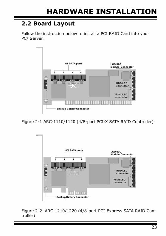
2.2 Board Layout
Follow the instruction below to install a PCI RAID Card into your PC/ Server.
Figure 2-1 ARC-1110/1120 (4/8-port PCI-X SATA RAID Controller)
Figure 2-2 ARC-1210/1220 (4/8-port PCI-Express SATA RAID Con-troller)
HARDWARE INSTALLATION
24
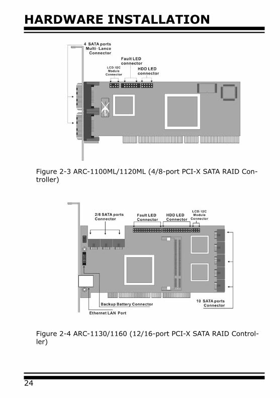
Figure 2-3 ARC-1100ML/1120ML (4/8-port PCI-X SATA RAID Con-troller)
Figure 2-4 ARC-1130/1160 (12/16-port PCI-X SATA RAID Control-ler)
HARDWARE INSTALLATION
25
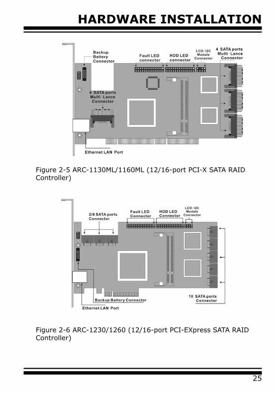
Figure 2-5 ARC-1130ML/1160ML (12/16-port PCI-X SATA RAID Controller)
Figure 2-6 ARC-1230/1260 (12/16-port PCI-EXpress SATA RAID Controller)
HARDWARE INSTALLATION
26
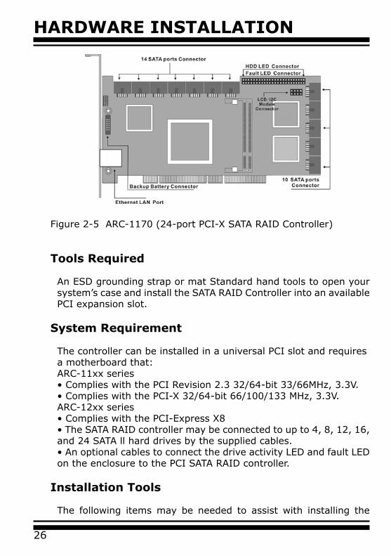
Figure 2-5 ARC-1170 (24-port PCI-X SATA RAID Controller)
Tools Required
An ESD grounding strap or mat Standard hand tools to open your system’s case and install the SATA RAID Controller into an available PCI expansion slot.
System Requirement
The controller can be installed in a universal PCI slot and requires a motherboard that:ARC-11xx series• Complies with the PCI Revision 2.3 32/64-bit 33/66MHz, 3.3V.• Complies with the PCI-X 32/64-bit 66/100/133 MHz, 3.3V.ARC-12xx series• Complies with the PCI-Express X8• The SATA RAID controller may be connected to up to 4, 8, 12, 16, and 24 SATA ll hard drives by the supplied cables.• An optional cables to connect the drive activity LED and fault LED on the enclosure to the PCI SATA RAID controller.
Installation Tools
The following items may be needed to assist with installing the
HARDWARE INSTALLATION
27
SATA RAID adapter into an available PCI expansion slot.• Small screwdriver• Host system hardware manuals and manuals for disk or enclo-sure being installed.
Personal Safety Information
To ensure you personal safety, as well as the safety of your equip-ment:• Always wear a grounded strap or work on an ESD-protective mat.• Before opening the system cabinet, turn off power switches and unplug the power cords. Do no reconnect the power cords until you have replaced the covers.
Warning:
High voltages may be found inside computer equipment. Before install-ing any of the hardware in this package or removing the protective cov-ers of any computer equipment, turn off power switches and disconnect power cords. Do not reconnect the power cords until you have replaced the covers.
Electrostatic Discharge
Static electricity can be a serious danger to the electronic com-ponents on this SATA RAID adapter. To avoid damage caused by electrostatic discharge, observe the following precautions:• Don’t remove the SATA RAID controller from its anti-static pack-aging until you are ready to install it into a computer case.• Handle the SATA RAID Controller by its edges or by the mounting metal bracket at its two ends.• Before you handle the SATA RAID controller in any way, touch a grounded, anti-static surface, such as an unpainted portion of the system chassis, for a few seconds to discharge any built-up static electricity.
2.3 Installation
Follow the instruction below to install a PCI RAID Card into your PC/ Server.

HARDWARE INSTALLATION
28
Step 1. Unpack
Unpack and remove the PCI RAID card from the package. Inspect it carefully, if anything is missing or damaged, contact your local dealer.
Step 2. Power PC/Server Off
Turn off computer and remove the AC power cord. Remove the system’s cover. See the computer system documentation for in-struction.Step 3. Install the PCI RAID Cards
To install the SATA RAID adapter, remove the mounting screw and existing bracket from the rear panel behind the selected PCI slot. Align the gold-fingered edge on the card with the selected PCI ex-pansion slot . Press down gently but firmly to ensure that the card is properly seated in the slot, as shown in Figure 2-4. Then screw the bracket into the computer chassis. The card can fit in both PCI and PCI-X slots. It can get the best performance while the SATA RAID controller runs in the 64-bit/133MHz PCI-X slot.
Figure 2-7 Insert PCI RAID Card into a PCI slot
HARDWARE INSTALLATION
29
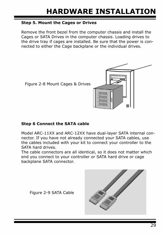
Step 6 Connect the SATA cable
Model ARC-11XX and ARC-12XX have dual-layer SATA internal con-nector. If you have not already connected your SATA cables, use the cables included with your kit to connect your controller to the SATA hard drives.The cable connectors are all identical, so it does not matter which end you connect to your controller or SATA hard drive or cage backplane SATA connector.
Figure 2-9 SATA Cable
Figure 2-8 Mount Cages & Drives
Step 5. Mount the Cages or Drives
Remove the front bezel from the computer chassis and install the Cages or SATA Drives in the computer chassis. Loading drives to the drive tray if cages are installed. Be sure that the power is con-nected to either the Cage backplane or the individual drives.
HARDWARE INSTALLATION
30
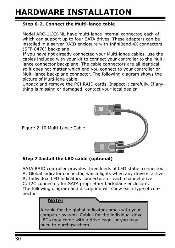
Step 7 Install the LED cable (optional)
SATA RAID controller provides three kinds of LED status connector.A: Global indicator connector, which lights when any drive is active.B: Individual LED indicators connector, for each channel drive.C: I2C connector, for SATA proprietary backplane enclosure.The following diagram and discription will show each type of con-nector.
Note:
A cable for the global indicator comes with your computer system. Cables for the individual drive LEDs may come with a drive cage, or you may need to purchase them.
Figure 2-10 Multi-Lance Cable
Step 6-2. Connect the Multi-lance cable
Model ARC-11XX-ML have multi-lance internal connector, each of which can support up to four SATA drives. These adapters can be installed in a server RAID enclosure with InfiniBand 4X connectors (SFF-8470) backplane.If you have not already connected your Multi-lance cables, use the cables included with your kit to connect your controller to the Multi-lance connector backplane. The cable connectors are all identical, so it does not matter which end you connect to your controller or Multi-lance backplane connector. The following diagram shows the picture of Multi-lane cable.Unpack and remove the PCI RAID cards. Inspect it carefully. If any-thing is missing or damaged, contact your local dealer.
HARDWARE INSTALLATION
31
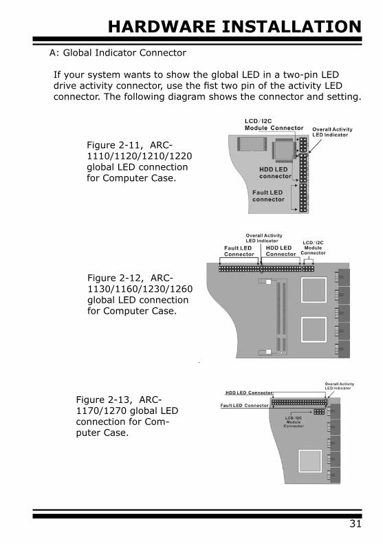
Figure 2-13, ARC-1170/1270 global LED connection for Com-puter Case.
A: Global Indicator Connector
If your system wants to show the global LED in a two-pin LED drive activity connector, use the fist two pin of the activity LED connector. The following diagram shows the connector and setting.
Figure 2-11, ARC-1110/1120/1210/1220 global LED connection for Computer Case.
Figure 2-12, ARC-1130/1160/1230/1260 global LED connection for Computer Case.
HARDWARE INSTALLATION
32
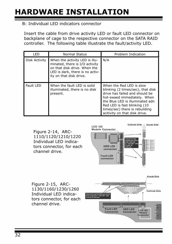
LED Normal Status Problem Indication
Disk Activity When the activity LED is illu-minated, there is I/O activity on that disk drive. When the LED is dark, there is no activ-ity on that disk drive.
N/A
Fault LED When the fault LED is solid illuminated, there is no disk present.
When the Red LED is slow blinking (2 times/sec), that disk drive has failed and should be hot-swaed immediately. When the Blue LED is illuminated adn Red LED is fast blinking (10 times/sec) there is rebuilding acitivity on that disk drive.
Figure 2-14, ARC-1110/1120/1210/1220 Individual LED indica-tors connector, for each channel drive.
B: Individual LED indicators connector
Insert the cable from drive activity LED or fault LED connector on backplane of cage to the respective connector on the SATA RAID controller. The following table illustrate the fault/activity LED.
Figure 2-15, ARC-1130/1160/1230/1260 Individual LED indica-tors connector, for each channel drive.
HARDWARE INSTALLATION
33
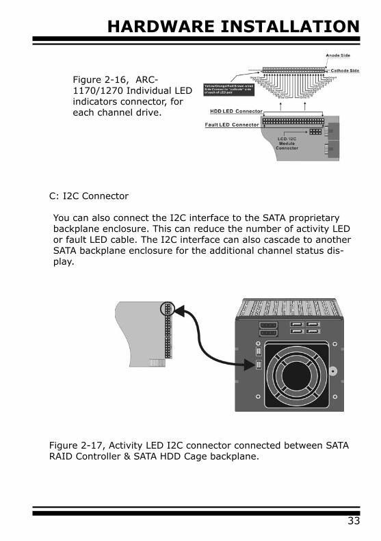
Figure 2-17, Activity LED I2C connector connected between SATA RAID Controller & SATA HDD Cage backplane.
C: I2C Connector
You can also connect the I2C interface to the SATA proprietary backplane enclosure. This can reduce the number of activity LED or fault LED cable. The I2C interface can also cascade to another SATA backplane enclosure for the additional channel status dis-play.
Figure 2-16, ARC-1170/1270 Individual LED indicators connector, for each channel drive.
HARDWARE INSTALLATION
34
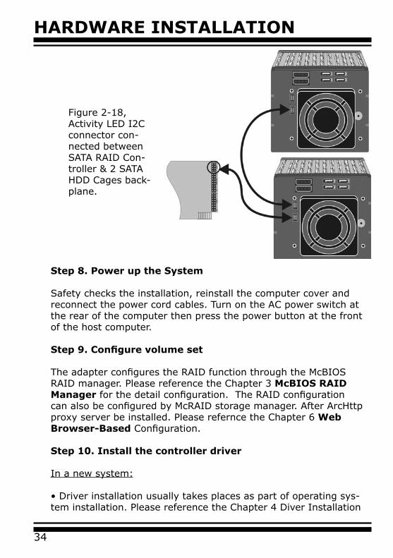
Figure 2-18, Activity LED I2C connector con-nected between SATA RAID Con-troller & 2 SATA HDD Cages back-plane.
Step 8. Power up the System
Safety checks the installation, reinstall the computer cover and reconnect the power cord cables. Turn on the AC power switch at the rear of the computer then press the power button at the front of the host computer.
Step 9. Configure volume set
The adapter configures the RAID function through the McBIOS RAID manager. Please reference the Chapter 3 McBIOS RAID Manager for the detail configuration. The RAID configuration can also be configured by McRAID storage manager. After ArcHttp proxy server be installed. Please refernce the Chapter 6 Web Browser-Based Configuration.
Step 10. Install the controller driver
In a new system:
• Driver installation usually takes places as part of operating sys-tem installation. Please reference the Chapter 4 Diver Installation

HARDWARE INSTALLATION
35
Step 11. Install ArcHttp proxy Server
The SATA RAID controller firmware has embedded the web-browser RAID manager and SNMP agent function. ArcHttp Proxy driver will enable it. The Browser-based RAID manager provides all of the creation, management, and monitor SATA RAID controller status. Please reference the Chapter 5 for the detail ArcHtt proxy server installation. The SNM agent function please reference appendix C.
Step 12. Determining the Boot sequences
SATA RAID is a bootable controller. If your system already con-tains a bootable device with an installed operating system, you can set up your system to boot a second operating system from the new controller. To add a second bootable controller, you may need to enter Setup and change the device boot sequence so that the SATA RAID controller heads the list. If system BIOS Setup does not allow this change, your system may not be configurable to allow the SATA RAID controller to act as a second boot device.Summary Of the installation
The flow chart below describes the installation procedures for SATA RAID controller. These procedures included hardware installa-tion, the creation and configuration of a RAID volume through the McBIOS, OS installation and installation of SATA RAID controller software.
Note:
Look for further release version driver of Linux and Free-BSD:
• See the Driver Library at http://www.areca.com.tw
for the detail installation procedure.
In an existing system:
• Install the controller driver to the existing operating system. Please reference the Chapter 4 Driver Installation for the detail installation procedure.
HARDWARE INSTALLATION
36
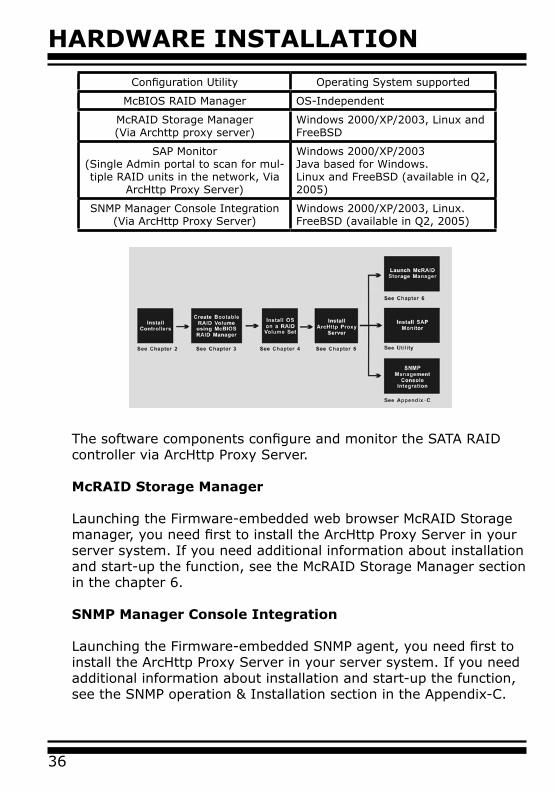
Configuration Utility Operating System supported
McBIOS RAID Manager OS-Independent
McRAID Storage Manager(Via Archttp proxy server)
Windows 2000/XP/2003, Linux and FreeBSD
SAP Monitor(Single Admin portal to scan for mul-tiple RAID units in the network, Via
ArcHttp Proxy Server)
Windows 2000/XP/2003Java based for Windows.Linux and FreeBSD (available in Q2, 2005)
SNMP Manager Console Integration(Via ArcHttp Proxy Server)
Windows 2000/XP/2003, Linux. FreeBSD (available in Q2, 2005)
The software components configure and monitor the SATA RAID controller via ArcHttp Proxy Server.
McRAID Storage Manager
Launching the Firmware-embedded web browser McRAID Storage manager, you need first to install the ArcHttp Proxy Server in your server system. If you need additional information about installation and start-up the function, see the McRAID Storage Manager section in the chapter 6.
SNMP Manager Console Integration
Launching the Firmware-embedded SNMP agent, you need first to install the ArcHttp Proxy Server in your server system. If you need additional information about installation and start-up the function, see the SNMP operation & Installation section in the Appendix-C.
HARDWARE INSTALLATION
37
Single Admin Portal (SAP) Monitor
Scan for multiple RAID units in the network and monitor the con-troller set status. It also includes disks stress test utility to kick out disks meeting marginal spec before the RAID unit is actually put on-line for real business.
For additional information, see the Utility manual in the package CD-ROM or download from the web site http://www.areca.com.tw.
BIOS CONFIGURATION
38
3. McBIOS RAID ManagerThe mainboard BIOS automatically configures the SATA RAID controller parameter at power-up;
• I/O Port Address• Interrupt channel(IRQ) • Adapter ROM Base Address
Use McBIOS to further configure the SATA RAID adapter to suit your operating system.
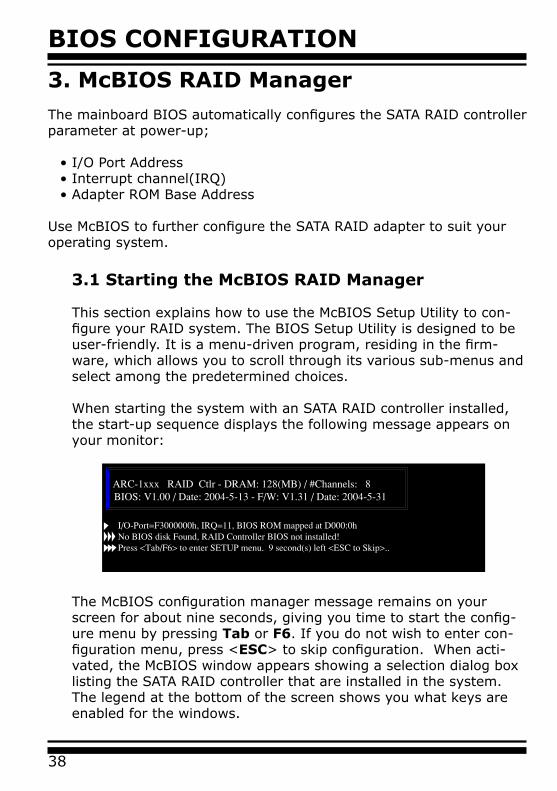
3.1 Starting the McBIOS RAID Manager
This section explains how to use the McBIOS Setup Utility to con-figure your RAID system. The BIOS Setup Utility is designed to be user-friendly. It is a menu-driven program, residing in the firm-ware, which allows you to scroll through its various sub-menus and select among the predetermined choices.
When starting the system with an SATA RAID controller installed, the start-up sequence displays the following message appears on your monitor:
The McBIOS configuration manager message remains on your screen for about nine seconds, giving you time to start the config-ure menu by pressing Tab or F6. If you do not wish to enter con-figuration menu, press <ESC> to skip configuration. When acti-vated, the McBIOS window appears showing a selection dialog box listing the SATA RAID controller that are installed in the system.The legend at the bottom of the screen shows you what keys are enabled for the windows.
BIOS CONFIGURATION
39
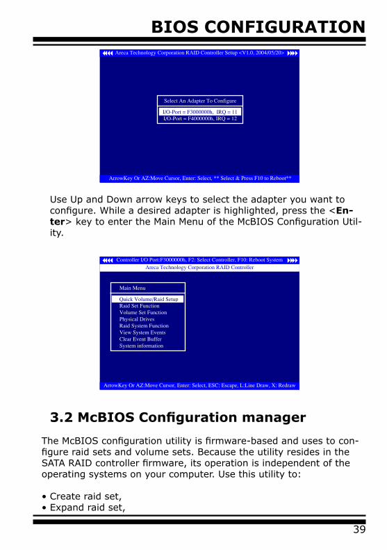
Use Up and Down arrow keys to select the adapter you want to configure. While a desired adapter is highlighted, press the <En-ter> key to enter the Main Menu of the McBIOS Configuration Util-ity.
3.2 McBIOS Configuration manager
The McBIOS configuration utility is firmware-based and uses to con-figure raid sets and volume sets. Because the utility resides in the SATA RAID controller firmware, its operation is independent of the operating systems on your computer. Use this utility to:
• Create raid set,• Expand raid set,
BIOS CONFIGURATION
40
3.4 Designating Drives as Hot Spares
All unused disk drive that is not part of a raid set can be created as a Hot Spare. The Quick Volume/Raid Setup configuration will automatically add the spare disk drive with the raid level for user to select. For the Raid Set Function configuration, user can use the Create Hot Spare option to define the hot spare disk drive.A Hot Spare disk drive can be created when you choose the Cre-ate Hot Spare option in the Raid Set Function, all unused physical devices connected to the current controller appear: Select the target disk by clicking on the appropriate check box.Press the Enter key to select a disk drive, and press Yes in the Create Hot Spare to designate it as a hot spare.
• Define volume set,• Add physical drive, • Modify volume set,• Modify RAID level/stripe size,• Define pass-through disk drives,• Modify system function, and• Designate drives as hot spares.
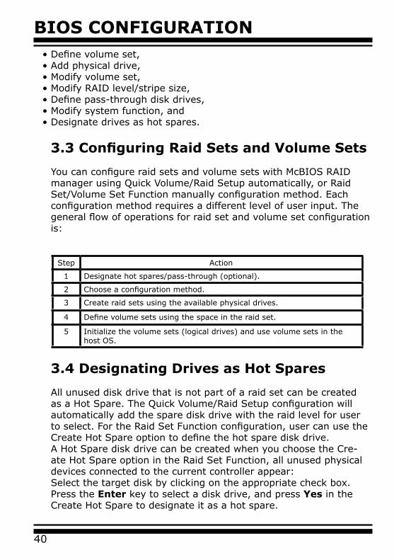
3.3 Configuring Raid Sets and Volume Sets
You can configure raid sets and volume sets with McBIOS RAID manager using Quick Volume/Raid Setup automatically, or Raid Set/Volume Set Function manually configuration method. Each configuration method requires a different level of user input. The general flow of operations for raid set and volume set configuration is:
Step Action
1 Designate hot spares/pass-through (optional).
2 Choose a configuration method.
3 Create raid sets using the available physical drives.
4 Define volume sets using the space in the raid set.
5 Initialize the volume sets (logical drives) and use volume sets in the host OS.
BIOS CONFIGURATION
41
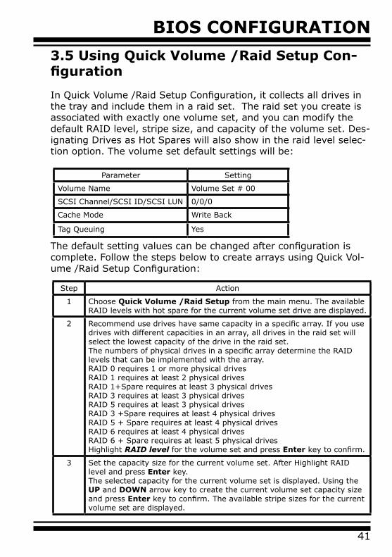
3.5 Using Quick Volume /Raid Setup Con-figuration
In Quick Volume /Raid Setup Configuration, it collects all drives in the tray and include them in a raid set. The raid set you create is associated with exactly one volume set, and you can modify the default RAID level, stripe size, and capacity of the volume set. Des-ignating Drives as Hot Spares will also show in the raid level selec-tion option. The volume set default settings will be:
Parameter Setting
Volume Name Volume Set # 00
SCSI Channel/SCSI ID/SCSI LUN 0/0/0
Cache Mode Write Back
Tag Queuing Yes
The default setting values can be changed after configuration is complete. Follow the steps below to create arrays using Quick Vol-ume /Raid Setup Configuration:
Step Action
1 Choose Quick Volume /Raid Setup from the main menu. The available RAID levels with hot spare for the current volume set drive are displayed.
2 Recommend use drives have same capacity in a specific array. If you use drives with different capacities in an array, all drives in the raid set will select the lowest capacity of the drive in the raid set.The numbers of physical drives in a specific array determine the RAID levels that can be implemented with the array.RAID 0 requires 1 or more physical drivesRAID 1 requires at least 2 physical drivesRAID 1+Spare requires at least 3 physical drivesRAID 3 requires at least 3 physical drives RAID 5 requires at least 3 physical drivesRAID 3 +Spare requires at least 4 physical drivesRAID 5 + Spare requires at least 4 physical drivesRAID 6 requires at least 4 physical drivesRAID 6 + Spare requires at least 5 physical drivesHighlight RAID level for the volume set and press Enter key to confirm.
3 Set the capacity size for the current volume set. After Highlight RAID level and press Enter key.The selected capacity for the current volume set is displayed. Using the UP and DOWN arrow key to create the current volume set capacity size and press Enter key to confirm. The available stripe sizes for the current volume set are displayed.
BIOS CONFIGURATION
42
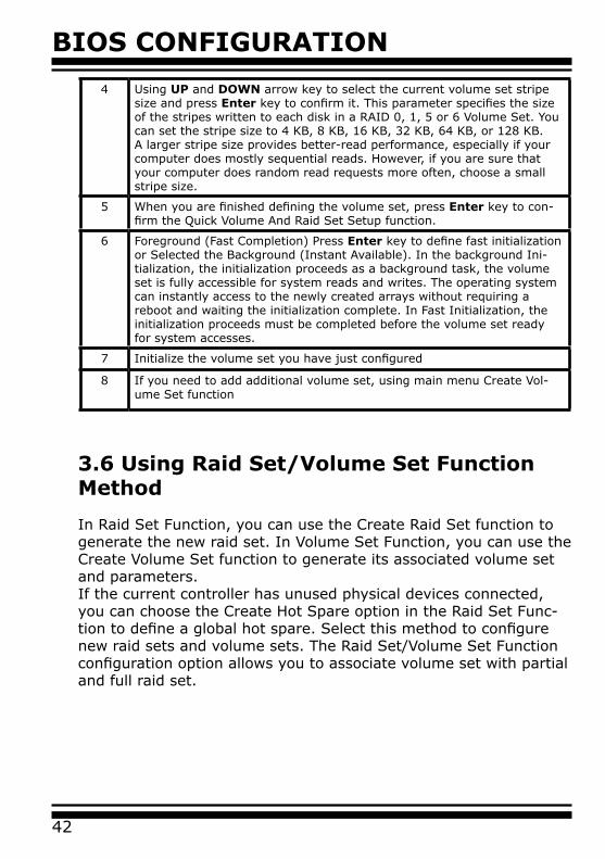
3.6 Using Raid Set/Volume Set Function Method
In Raid Set Function, you can use the Create Raid Set function to generate the new raid set. In Volume Set Function, you can use the Create Volume Set function to generate its associated volume set and parameters. If the current controller has unused physical devices connected, you can choose the Create Hot Spare option in the Raid Set Func-tion to define a global hot spare. Select this method to configure new raid sets and volume sets. The Raid Set/Volume Set Function configuration option allows you to associate volume set with partial and full raid set.
4 Using UP and DOWN arrow key to select the current volume set stripe size and press Enter key to confirm it. This parameter specifies the size of the stripes written to each disk in a RAID 0, 1, 5 or 6 Volume Set. You can set the stripe size to 4 KB, 8 KB, 16 KB, 32 KB, 64 KB, or 128 KB. A larger stripe size provides better-read performance, especially if your computer does mostly sequential reads. However, if you are sure that your computer does random read requests more often, choose a small stripe size.
5 When you are finished defining the volume set, press Enter key to con-firm the Quick Volume And Raid Set Setup function.
6 Foreground (Fast Completion) Press Enter key to define fast initialization or Selected the Background (Instant Available). In the background Ini-tialization, the initialization proceeds as a background task, the volume set is fully accessible for system reads and writes. The operating system can instantly access to the newly created arrays without requiring a reboot and waiting the initialization complete. In Fast Initialization, the initialization proceeds must be completed before the volume set ready for system accesses.
7 Initialize the volume set you have just configured
8 If you need to add additional volume set, using main menu Create Vol-ume Set function
BIOS CONFIGURATION
43
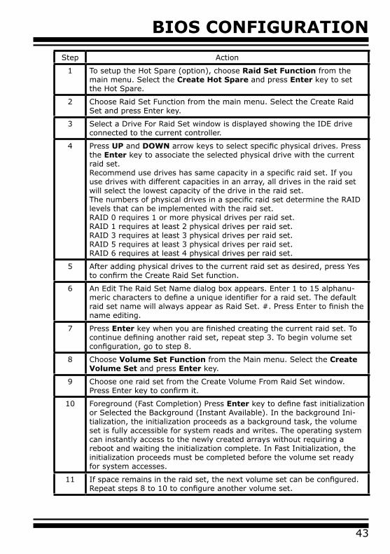
Step Action
1 To setup the Hot Spare (option), choose Raid Set Function from the main menu. Select the Create Hot Spare and press Enter key to set the Hot Spare.
2 Choose Raid Set Function from the main menu. Select the Create Raid Set and press Enter key.
3 Select a Drive For Raid Set window is displayed showing the IDE drive connected to the current controller.
4 Press UP and DOWN arrow keys to select specific physical drives. Press the Enter key to associate the selected physical drive with the current raid set.Recommend use drives has same capacity in a specific raid set. If you use drives with different capacities in an array, all drives in the raid set will select the lowest capacity of the drive in the raid set.The numbers of physical drives in a specific raid set determine the RAID levels that can be implemented with the raid set.RAID 0 requires 1 or more physical drives per raid set.RAID 1 requires at least 2 physical drives per raid set.RAID 3 requires at least 3 physical drives per raid set.RAID 5 requires at least 3 physical drives per raid set.RAID 6 requires at least 4 physical drives per raid set.
5 After adding physical drives to the current raid set as desired, press Yes to confirm the Create Raid Set function.
6 An Edit The Raid Set Name dialog box appears. Enter 1 to 15 alphanu-meric characters to define a unique identifier for a raid set. The default raid set name will always appear as Raid Set. #. Press Enter to finish the name editing.
7 Press Enter key when you are finished creating the current raid set. To continue defining another raid set, repeat step 3. To begin volume set configuration, go to step 8.
8 Choose Volume Set Function from the Main menu. Select the Create Volume Set and press Enter key.
9 Choose one raid set from the Create Volume From Raid Set window. Press Enter key to confirm it.
10 Foreground (Fast Completion) Press Enter key to define fast initialization or Selected the Background (Instant Available). In the background Ini-tialization, the initialization proceeds as a background task, the volume set is fully accessible for system reads and writes. The operating system can instantly access to the newly created arrays without requiring a reboot and waiting the initialization complete. In Fast Initialization, the initialization proceeds must be completed before the volume set ready for system accesses.
11 If space remains in the raid set, the next volume set can be configured. Repeat steps 8 to 10 to configure another volume set.
BIOS CONFIGURATION
44
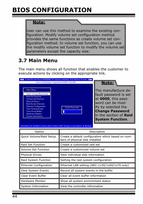
3.7 Main Menu
The main menu shows all function that enables the customer to execute actions by clicking on the appropriate link.
Note:
User can use this method to examine the existing con-figuration. Modify volume set configuration method provides the same functions as create volume set con-figuration method. In volume set function, you can use the modify volume set function to modify the volume set parameters except the capacity size:
Note:
The manufacture de-fault password is set at 0000, this pass-word can be mod-ify by selected the Change Password in the section of Raid System Function.
Option Description
Quick Volume/Raid Setup Create a default configuration which based on num-bers of physical disk installed
Raid Set Function Create a customized raid set
Volume Set Function Create a customized volume set
Physical Drives View individual disk information
Raid System Function Setting the raid system configuration
Ethernet Configuration Ethernet LAN setting (ARC-1x30/1x60/1x70 only)
View System Events Record all system events in the buffer
Clear Event Buffer Clear all event buffer information
Hardware Monitor Show all system environment status
System Information View the controller information
BIOS CONFIGURATION
45
This password option allows user to set or clear the raid controller’s password protection feature. Once the password has been set, the user can only monitor and configure the raid controller by providing the correct password. The password is used to protect the internal RAID controller from unauthorized entry. The controller will check the password only when entering the Main menu from the initial screen. The RAID controller will automatically go back to the initial screen when it does not receive any command in twenty seconds.
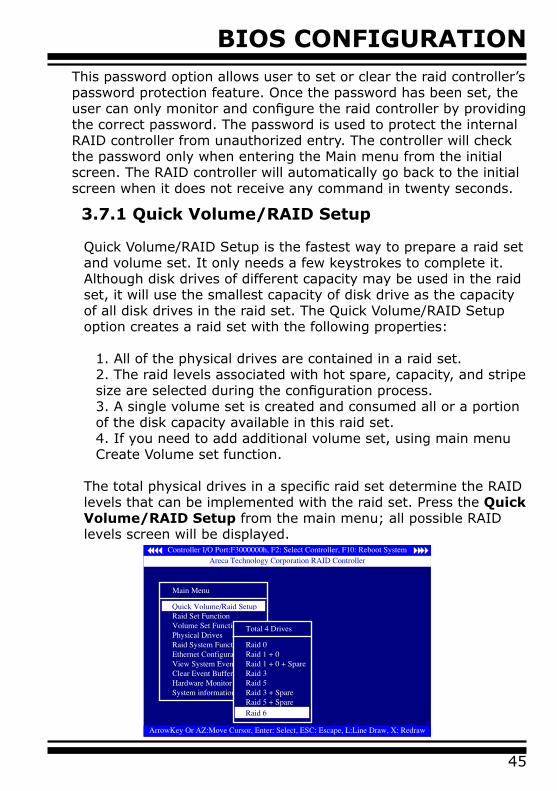
3.7.1 Quick Volume/RAID Setup
Quick Volume/RAID Setup is the fastest way to prepare a raid set and volume set. It only needs a few keystrokes to complete it. Although disk drives of different capacity may be used in the raid set, it will use the smallest capacity of disk drive as the capacity of all disk drives in the raid set. The Quick Volume/RAID Setup option creates a raid set with the following properties:
1. All of the physical drives are contained in a raid set.2. The raid levels associated with hot spare, capacity, and stripe size are selected during the configuration process.3. A single volume set is created and consumed all or a portion of the disk capacity available in this raid set.4. If you need to add additional volume set, using main menu Create Volume set function.
The total physical drives in a specific raid set determine the RAID levels that can be implemented with the raid set. Press the Quick Volume/RAID Setup from the main menu; all possible RAID levels screen will be displayed.
BIOS CONFIGURATION
46
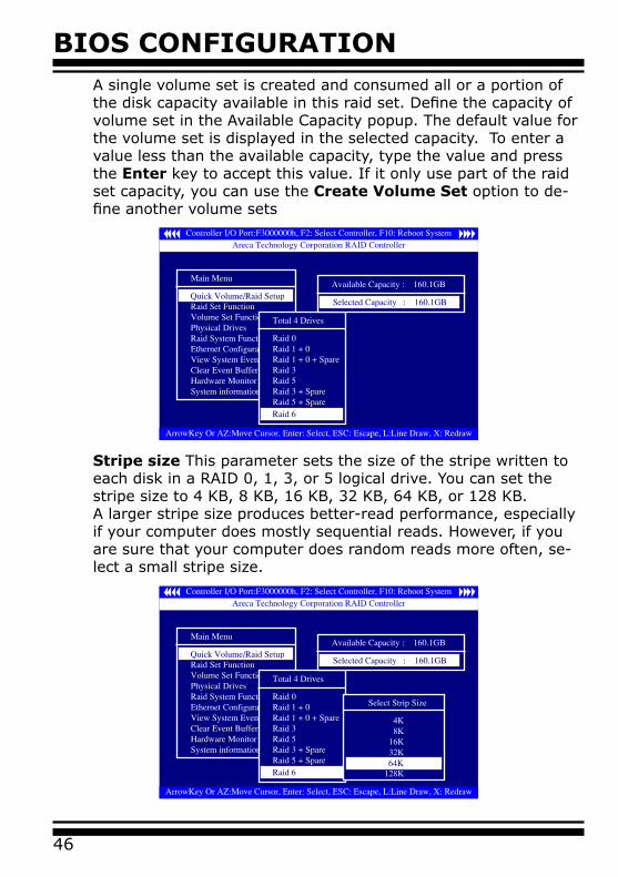
A single volume set is created and consumed all or a portion of the disk capacity available in this raid set. Define the capacity of volume set in the Available Capacity popup. The default value for the volume set is displayed in the selected capacity. To enter a value less than the available capacity, type the value and press the Enter key to accept this value. If it only use part of the raid set capacity, you can use the Create Volume Set option to de-fine another volume sets
Stripe size This parameter sets the size of the stripe written to each disk in a RAID 0, 1, 3, or 5 logical drive. You can set the stripe size to 4 KB, 8 KB, 16 KB, 32 KB, 64 KB, or 128 KB.A larger stripe size produces better-read performance, especially if your computer does mostly sequential reads. However, if you are sure that your computer does random reads more often, se-lect a small stripe size.
BIOS CONFIGURATION
47
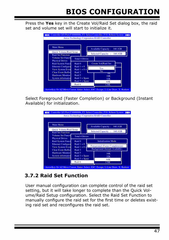
Select Foreground (Faster Completion) or Background (Instant Available) for initialization.
Press the Yes key in the Create Vol/Raid Set dialog box, the raid set and volume set will start to initialize it.
3.7.2 Raid Set Function
User manual configuration can complete control of the raid set setting, but it will take longer to complete than the Quick Vol-ume/Raid Setup configuration. Select the Raid Set Function to manually configure the raid set for the first time or deletes exist-ing raid set and reconfigures the raid set.
BIOS CONFIGURATION
48
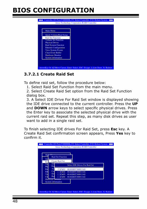
3.7.2.1 Create Raid Set
To define raid set, follow the procedure below:1. Select Raid Set Function from the main menu.2. Select Create Raid Set option from the Raid Set Function dialog box.3. A Select IDE Drive For Raid Set window is displayed showing the IDE drive connected to the current controller. Press the UP and DOWN arrow keys to select specific physical drives. Press the Enter key to associate the selected physical drive with the current raid set. Repeat this step, as many disk drives as user want to add in a single raid set.
To finish selecting IDE drives For Raid Set, press Esc key. A Create Raid Set confirmation screen appears, Press Yes key to confirm it.
BIOS CONFIGURATION
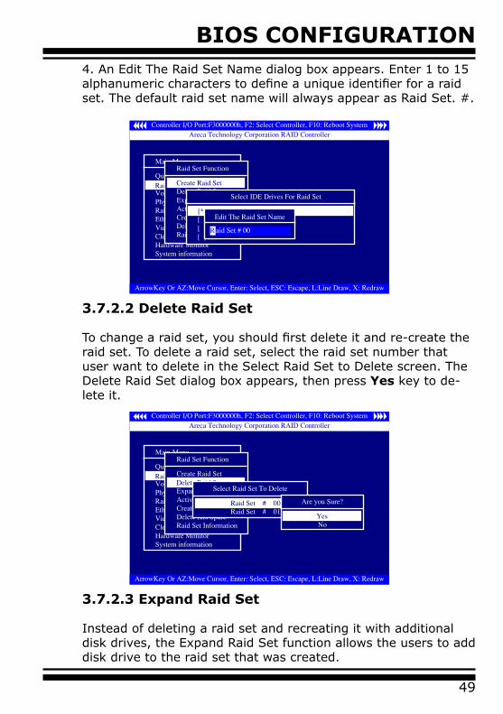
49
4. An Edit The Raid Set Name dialog box appears. Enter 1 to 15 alphanumeric characters to define a unique identifier for a raid set. The default raid set name will always appear as Raid Set. #.
3.7.2.2 Delete Raid Set
To change a raid set, you should first delete it and re-create the raid set. To delete a raid set, select the raid set number that user want to delete in the Select Raid Set to Delete screen. The Delete Raid Set dialog box appears, then press Yes key to de-lete it.
3.7.2.3 Expand Raid Set
Instead of deleting a raid set and recreating it with additional disk drives, the Expand Raid Set function allows the users to add disk drive to the raid set that was created.
BIOS CONFIGURATION
50
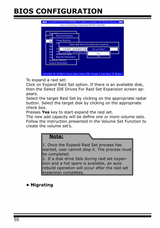
To expand a raid set:Click on Expand Raid Set option. If there is an available disk, then the Select IDE Drives For Raid Set Expansion screen ap-pears.Select the target Raid Set by clicking on the appropriate radial button. Select the target disk by clicking on the appropriate check box.Presses Yes key to start expand the raid set.The new add capacity will be define one or more volume sets. Follow the instruction presented in the Volume Set Function to create the volume set’s.
Note:
1. Once the Expand Raid Set process has started, user cannot stop it. The process must be completed.2. If a disk drive fails during raid set expan-sion and a hot spare is available, an auto rebuild operation will occur after the raid set expansion completes.
• Migrating
BIOS CONFIGURATION
51
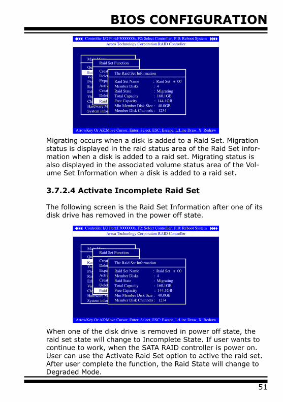
Migrating occurs when a disk is added to a Raid Set. Migration status is displayed in the raid status area of the Raid Set infor-mation when a disk is added to a raid set. Migrating status is also displayed in the associated volume status area of the Vol-ume Set Information when a disk is added to a raid set.
3.7.2.4 Activate Incomplete Raid Set
The following screen is the Raid Set Information after one of its disk drive has removed in the power off state.
When one of the disk drive is removed in power off state, the raid set state will change to Incomplete State. If user wants to continue to work, when the SATA RAID controller is power on. User can use the Activate Raid Set option to active the raid set. After user complete the function, the Raid State will change to Degraded Mode.
BIOS CONFIGURATION
52
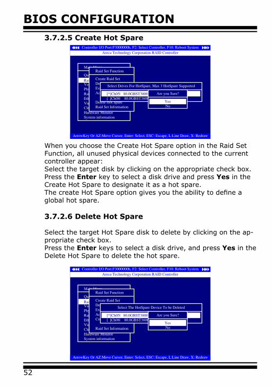
3.7.2.5 Create Hot Spare
When you choose the Create Hot Spare option in the Raid Set Function, all unused physical devices connected to the current controller appear: Select the target disk by clicking on the appropriate check box.Press the Enter key to select a disk drive and press Yes in the Create Hot Spare to designate it as a hot spare.The create Hot Spare option gives you the ability to define a global hot spare.
3.7.2.6 Delete Hot Spare
Select the target Hot Spare disk to delete by clicking on the ap-propriate check box.Press the Enter keys to select a disk drive, and press Yes in the Delete Hot Spare to delete the hot spare.
BIOS CONFIGURATION
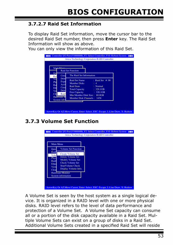
53
3.7.2.7 Raid Set Information
To display Raid Set information, move the cursor bar to the desired Raid Set number, then press Enter key. The Raid Set Information will show as above. You can only view the information of this Raid Set.
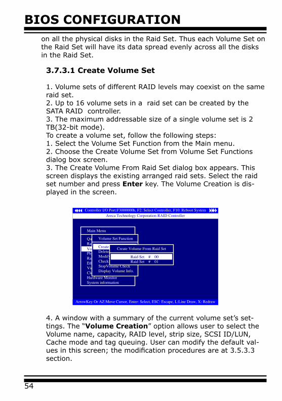
3.7.3 Volume Set Function
A Volume Set is seen by the host system as a single logical de-vice. It is organized in a RAID level with one or more physical disks. RAID level refers to the level of data performance and protection of a Volume Set. A Volume Set capacity can consume all or a portion of the disk capacity available in a Raid Set. Mul-tiple Volume Sets can exist on a group of disks in a Raid Set. Additional Volume Sets created in a specified Raid Set will reside
BIOS CONFIGURATION
54
on all the physical disks in the Raid Set. Thus each Volume Set on the Raid Set will have its data spread evenly across all the disks in the Raid Set.
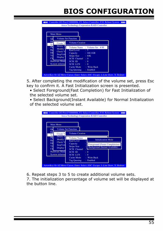
3.7.3.1 Create Volume Set
1. Volume sets of different RAID levels may coexist on the same raid set.2. Up to 16 volume sets in a raid set can be created by the SATA RAID controller.3. The maximum addressable size of a single volume set is 2 TB(32-bit mode).To create a volume set, follow the following steps:1. Select the Volume Set Function from the Main menu.2. Choose the Create Volume Set from Volume Set Functions dialog box screen.3. The Create Volume From Raid Set dialog box appears. This screen displays the existing arranged raid sets. Select the raid set number and press Enter key. The Volume Creation is dis-played in the screen.
4. A window with a summary of the current volume set’s set-tings. The “Volume Creation” option allows user to select the Volume name, capacity, RAID level, strip size, SCSI ID/LUN, Cache mode and tag queuing. User can modify the default val-ues in this screen; the modification procedures are at 3.5.3.3 section.
BIOS CONFIGURATION
55
5. After completing the modification of the volume set, press Esc key to confirm it. A Fast Initialization screen is presented.
• Select Foreground(Fast Completion) for Fast Initialization of the selected volume set.• Select Background(Instant Available) for Normal Initialization of the selected volume set.
6. Repeat steps 3 to 5 to create additional volume sets.7. The initialization percentage of volume set will be displayed at the button line.
BIOS CONFIGURATION
56
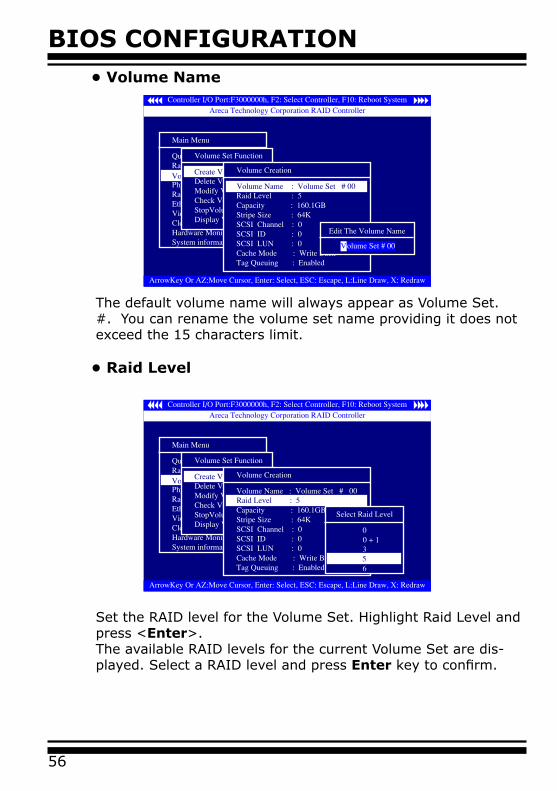
The default volume name will always appear as Volume Set. #. You can rename the volume set name providing it does not exceed the 15 characters limit.
• Raid Level
• Volume Name
Set the RAID level for the Volume Set. Highlight Raid Level and press <Enter>.The available RAID levels for the current Volume Set are dis-played. Select a RAID level and press Enter key to confirm.
BIOS CONFIGURATION
57
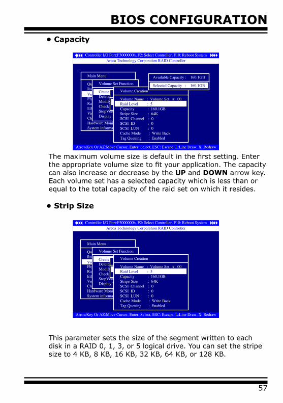
The maximum volume size is default in the first setting. Enter the appropriate volume size to fit your application. The capacity can also increase or decrease by the UP and DOWN arrow key. Each volume set has a selected capacity which is less than or equal to the total capacity of the raid set on which it resides.
• Strip Size
This parameter sets the size of the segment written to each disk in a RAID 0, 1, 3, or 5 logical drive. You can set the stripe size to 4 KB, 8 KB, 16 KB, 32 KB, 64 KB, or 128 KB.
• Capacity
BIOS CONFIGURATION
58
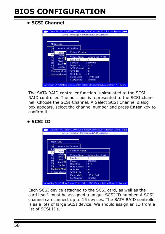
• SCSI Channel
The SATA RAID controller function is simulated to the SCSI RAID controller. The host bus is represented to the SCSI chan-nel. Choose the SCSI Channel. A Select SCSI Channel dialog box appears, select the channel number and press Enter key to confirm it.
• SCSI ID
Each SCSI device attached to the SCSI card, as well as the card itself, must be assigned a unique SCSI ID number. A SCSI channel can connect up to 15 devices. The SATA RAID controller is as a lots of large SCSI device. We should assign an ID from a list of SCSI IDs.
BIOS CONFIGURATION
59
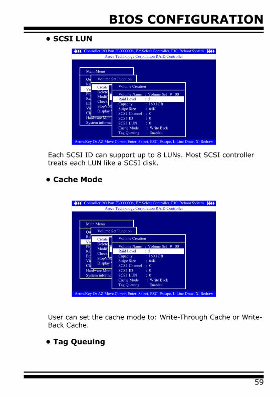
• SCSI LUN
Each SCSI ID can support up to 8 LUNs. Most SCSI controller treats each LUN like a SCSI disk.
• Cache Mode
User can set the cache mode to: Write-Through Cache or Write-Back Cache.
• Tag Queuing
BIOS CONFIGURATION
60
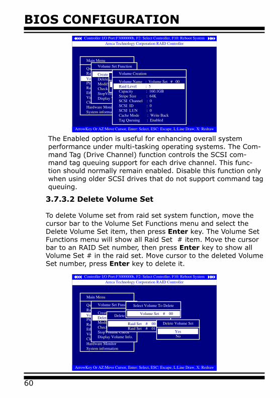
The Enabled option is useful for enhancing overall system performance under multi-tasking operating systems. The Com-mand Tag (Drive Channel) function controls the SCSI com-mand tag queuing support for each drive channel. This func-tion should normally remain enabled. Disable this function only when using older SCSI drives that do not support command tag queuing.
3.7.3.2 Delete Volume Set
To delete Volume set from raid set system function, move the cursor bar to the Volume Set Functions menu and select the Delete Volume Set item, then press Enter key. The Volume Set Functions menu will show all Raid Set # item. Move the cursor bar to an RAID Set number, then press Enter key to show all Volume Set # in the raid set. Move cursor to the deleted Volume Set number, press Enter key to delete it.
BIOS CONFIGURATION
61
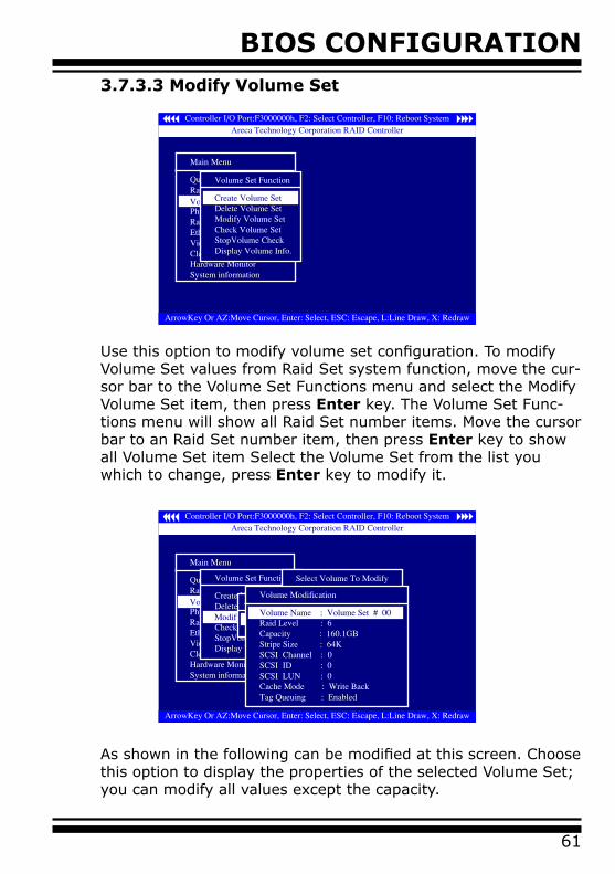
3.7.3.3 Modify Volume Set
Use this option to modify volume set configuration. To modify Volume Set values from Raid Set system function, move the cur-sor bar to the Volume Set Functions menu and select the Modify Volume Set item, then press Enter key. The Volume Set Func-tions menu will show all Raid Set number items. Move the cursor bar to an Raid Set number item, then press Enter key to show all Volume Set item Select the Volume Set from the list you which to change, press Enter key to modify it.
As shown in the following can be modified at this screen. Choose this option to display the properties of the selected Volume Set; you can modify all values except the capacity.
BIOS CONFIGURATION
62
• Volume Growth
Use this raid set expands to expand a raid set, when a disk is added to your system. The expand capacity can use to enlarge the volume set size or create another volume set. The modify volume set function can support the volume set expansion function. To expand volume set capacity value from raid set system function, move the cursor bar to the volume set volume capacity item and entry the capacity size. Tick on the Confirm The Operation and click on the Submit button to complete the action. The volume set start to expand.
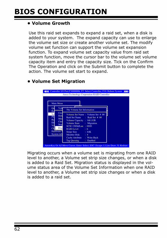
• Volume Set Migration
Migrating occurs when a volume set is migrating from one RAID level to another, a Volume set strip size changes, or when a disk is added to a Raid Set. Migration status is displayed in the vol-ume status area of the Volume Set Information when one RAID level to another, a Volume set strip size changes or when a disk is added to a raid set.
BIOS CONFIGURATION
63
Use this option to verify the correctness of the redundant data in a volume set. For example, in a system with dedicated parity, volume set check means computing the parity of the data disk drives and comparing the results to the contents of the dedicat-ed parity disk drive. To check Volume Set from Raid Set system function, move the cursor bar to the Volume Set Functions menu and select the Check Volume Set item, then press Enter key. The Volume Set Functions menu will show all Raid Set number items. Move the cursor bar to an Raid Set number item, then press Enter key to show all Volume Set item Select the Volume Set from the list you which to check, press Enter key to select it. After completing the selection, the confirmation screen ap-pears, presses Yes to start check.
3.7.3.5 Stop Volume Set Check
Use this option to stop all the Check Volume Set function.
3.7.3.4 Check Volume Set
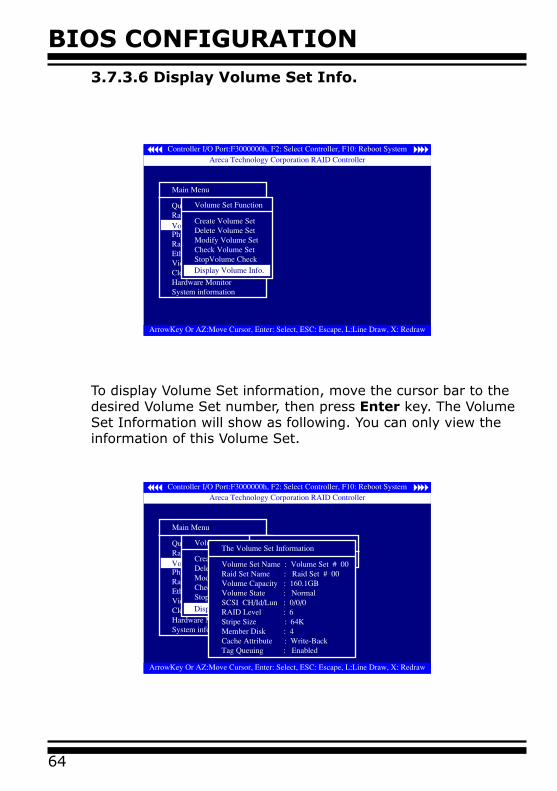
BIOS CONFIGURATION
64
3.7.3.6 Display Volume Set Info.
To display Volume Set information, move the cursor bar to the desired Volume Set number, then press Enter key. The Volume Set Information will show as following. You can only view the information of this Volume Set.
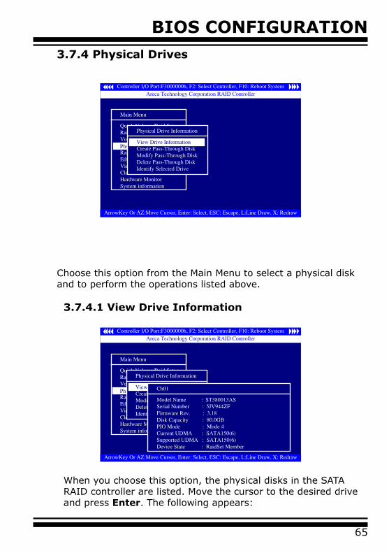
BIOS CONFIGURATION
65
3.7.4 Physical Drives
Choose this option from the Main Menu to select a physical disk and to perform the operations listed above.
3.7.4.1 View Drive Information
When you choose this option, the physical disks in the SATA RAID controller are listed. Move the cursor to the desired drive and press Enter. The following appears:
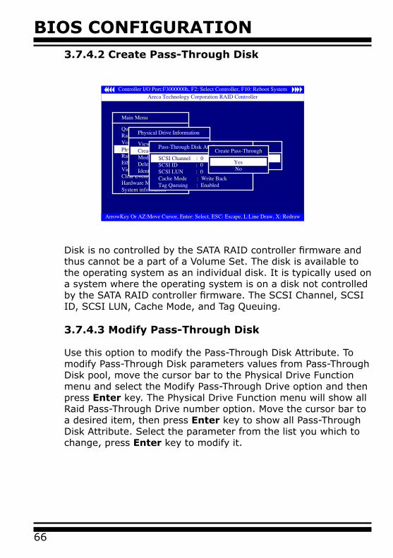
BIOS CONFIGURATION
66
3.7.4.2 Create Pass-Through Disk
Disk is no controlled by the SATA RAID controller firmware and thus cannot be a part of a Volume Set. The disk is available to the operating system as an individual disk. It is typically used on a system where the operating system is on a disk not controlled by the SATA RAID controller firmware. The SCSI Channel, SCSI ID, SCSI LUN, Cache Mode, and Tag Queuing.
3.7.4.3 Modify Pass-Through Disk
Use this option to modify the Pass-Through Disk Attribute. To modify Pass-Through Disk parameters values from Pass-Through Disk pool, move the cursor bar to the Physical Drive Function menu and select the Modify Pass-Through Drive option and then press Enter key. The Physical Drive Function menu will show all Raid Pass-Through Drive number option. Move the cursor bar to a desired item, then press Enter key to show all Pass-Through Disk Attribute. Select the parameter from the list you which to change, press Enter key to modify it.
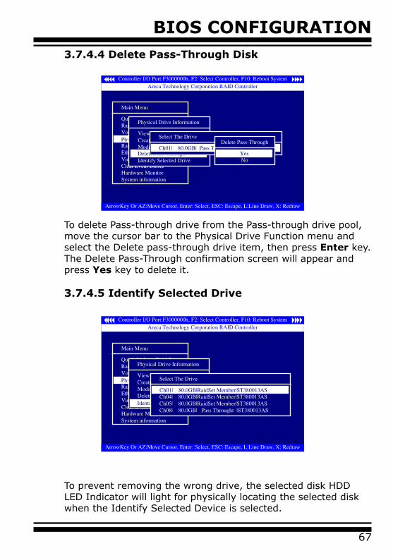
BIOS CONFIGURATION
67
3.7.4.4 Delete Pass-Through Disk
To delete Pass-through drive from the Pass-through drive pool, move the cursor bar to the Physical Drive Function menu and select the Delete pass-through drive item, then press Enter key. The Delete Pass-Through confirmation screen will appear and press Yes key to delete it.
3.7.4.5 Identify Selected Drive
To prevent removing the wrong drive, the selected disk HDD LED Indicator will light for physically locating the selected disk when the Identify Selected Device is selected.
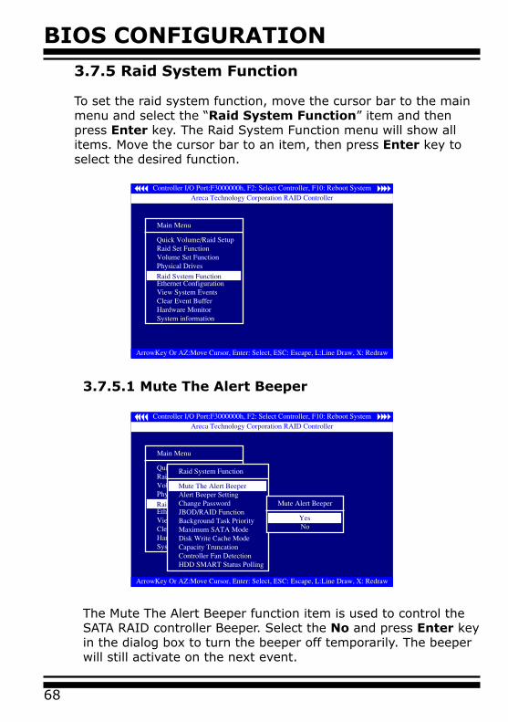
BIOS CONFIGURATION
68
3.7.5 Raid System Function
To set the raid system function, move the cursor bar to the main menu and select the “Raid System Function” item and then press Enter key. The Raid System Function menu will show all items. Move the cursor bar to an item, then press Enter key to select the desired function.
3.7.5.1 Mute The Alert Beeper
The Mute The Alert Beeper function item is used to control the SATA RAID controller Beeper. Select the No and press Enter key in the dialog box to turn the beeper off temporarily. The beeper will still activate on the next event.
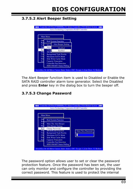
BIOS CONFIGURATION
69
3.7.5.2 Alert Beeper Setting
The Alert Beeper function item is used to Disabled or Enable the SATA RAID controller alarm tone generator. Select the Disabled and press Enter key in the dialog box to turn the beeper off.
3.7.5.3 Change Password
The password option allows user to set or clear the password protection feature. Once the password has been set, the user can only monitor and configure the controller by providing the correct password. This feature is used to protect the internal
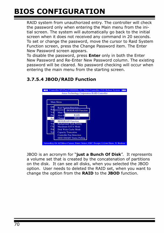
BIOS CONFIGURATION
70
RAID system from unauthorized entry. The controller will check the password only when entering the Main menu from the ini-tial screen. The system will automatically go back to the initial screen when it does not received any command in 20 seconds.To set or change the password, move the cursor to Raid System Function screen, press the Change Password item. The Enter New Password screen appears.To disable the password, press Enter only in both the Enter New Password and Re-Enter New Password column. The existing password will be cleared. No password checking will occur when entering the main menu from the starting screen.
3.7.5.4 JBOD/RAID Function
JBOD is an acronym for “just a Bunch Of Disk”. It represents a volume set that is created by the concatenation of partitions on the disk. It can see all disks, when you selected the JBOD option. User needs to deleted the RAID set, when you want to change the option from the RAID to the JBOD function.
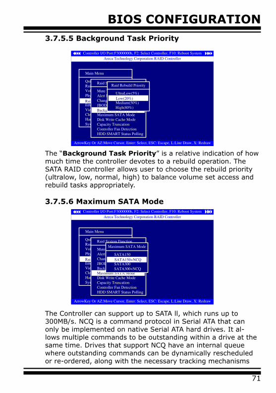
BIOS CONFIGURATION
71
3.7.5.5 Background Task Priority
The “Background Task Priority” is a relative indication of how much time the controller devotes to a rebuild operation. The SATA RAID controller allows user to choose the rebuild priority (ultralow, low, normal, high) to balance volume set access and rebuild tasks appropriately.
3.7.5.6 Maximum SATA Mode
The Controller can support up to SATA ll, which runs up to 300MB/s. NCQ is a command protocol in Serial ATA that can only be implemented on native Serial ATA hard drives. It al-lows multiple commands to be outstanding within a drive at the same time. Drives that support NCQ have an internal queue where outstanding commands can be dynamically rescheduled or re-ordered, along with the necessary tracking mechanisms
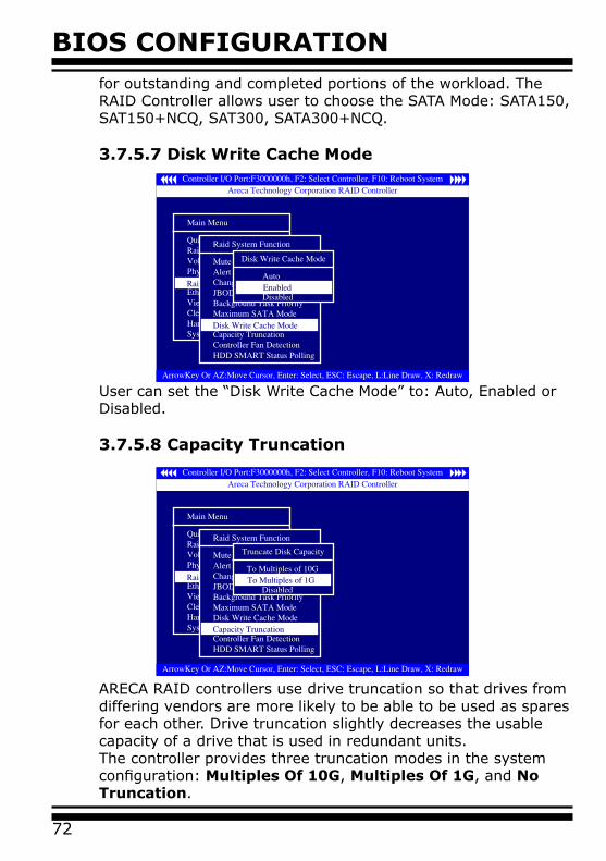
BIOS CONFIGURATION
72
for outstanding and completed portions of the workload. The RAID Controller allows user to choose the SATA Mode: SATA150, SAT150+NCQ, SAT300, SATA300+NCQ.
3.7.5.7 Disk Write Cache Mode
User can set the “Disk Write Cache Mode” to: Auto, Enabled or Disabled.
3.7.5.8 Capacity Truncation
ARECA RAID controllers use drive truncation so that drives from differing vendors are more likely to be able to be used as spares for each other. Drive truncation slightly decreases the usable capacity of a drive that is used in redundant units. The controller provides three truncation modes in the system configuration: Multiples Of 10G, Multiples Of 1G, and No Truncation.
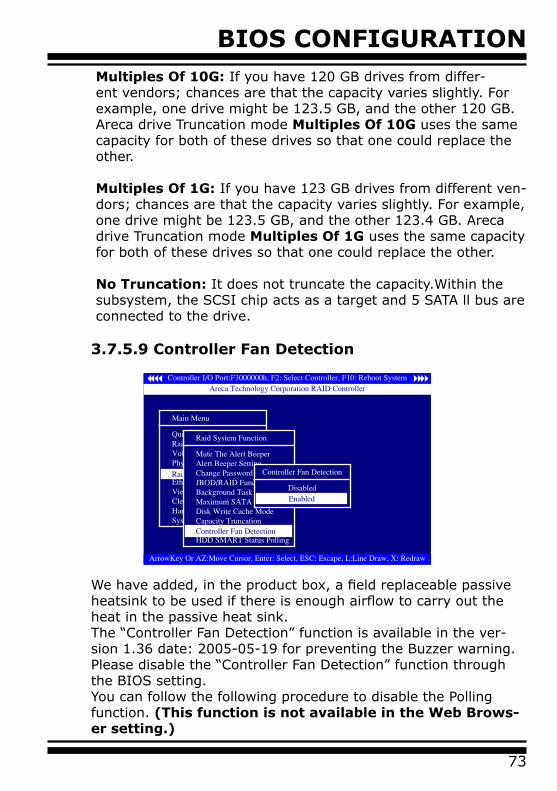
BIOS CONFIGURATION
73
Multiples Of 10G: If you have 120 GB drives from differ-ent vendors; chances are that the capacity varies slightly. For example, one drive might be 123.5 GB, and the other 120 GB. Areca drive Truncation mode Multiples Of 10G uses the same capacity for both of these drives so that one could replace the other.
Multiples Of 1G: If you have 123 GB drives from different ven-dors; chances are that the capacity varies slightly. For example, one drive might be 123.5 GB, and the other 123.4 GB. Areca drive Truncation mode Multiples Of 1G uses the same capacity for both of these drives so that one could replace the other.
No Truncation: It does not truncate the capacity.Within the subsystem, the SCSI chip acts as a target and 5 SATA ll bus are connected to the drive.
3.7.5.9 Controller Fan Detection
We have added, in the product box, a field replaceable passive heatsink to be used if there is enough airflow to carry out the heat in the passive heat sink. The “Controller Fan Detection” function is available in the ver-sion 1.36 date: 2005-05-19 for preventing the Buzzer warning.Please disable the “Controller Fan Detection” function through the BIOS setting.You can follow the following procedure to disable the Polling function. (This function is not available in the Web Brows-er setting.)
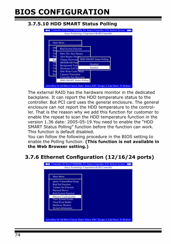
BIOS CONFIGURATION
74
3.7.5.10 HDD SMART Status Polling
The external RAID has the hardware monitor in the dedicated backplane. It can report the HDD temperature status to the controller. But PCI card uses the general enclosure. The general enclosure can not report the HDD temperature to the control-ler. That is the reason why we add this function for customer to enable the repeat to scan the HDD temperature function in the version 1.36 date: 2005-05-19.You need to enable the “HDD SMART Status Polling” function before the function can work. This function is default disabled.You can follow the following procedure in the BIOS setting to enable the Polling function. (This function is not available in the Web Browser setting.)
3.7.6 Ethernet Configuration (12/16/24 ports)
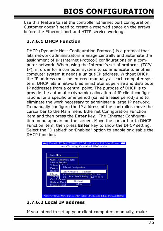
BIOS CONFIGURATION
75
3.7.6.2 Local IP address
If you intend to set up your client computers manually, make
Use this feature to set the controller Ethernet port configuration. Customer doesn’t need to create a reserved space on the arrays before the Ethernet port and HTTP service working.
3.7.6.1 DHCP Function
DHCP (Dynamic Host Configuration Protocol) is a protocol that lets network administrators manage centrally and automate the assignment of IP (Internet Protocol) configurations on a com-puter network. When using the Internet’s set of protocols (TCP/IP), in order for a computer system to communicate to another computer system it needs a unique IP address. Without DHCP, the IP address must be entered manually at each computer sys-tem. DHCP lets a network administrator supervise and distribute IP addresses from a central point. The purpose of DHCP is to provide the automatic (dynamic) allocation of IP client configu-rations for a specific time period (called a lease period) and to eliminate the work necessary to administer a large IP network.To manually configure the IP address of the controller, move the cursor bar to the Main menu Ethernet Configuration Function item and then press the Enter key. The Ethernet Configura-tion menu appears on the screen. Move the cursor bar to DHCP Function item, then press Enter key to show the DHCP setting. Select the “Disabled’ or ‘Enabled” option to enable or disable the DHCP function.
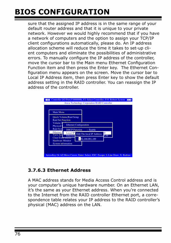
BIOS CONFIGURATION
76
sure that the assigned IP address is in the same range of your default router address and that it is unique to your private network. However we would highly recommend that if you have a network of computers and the option to assign your TCP/IP client configurations automatically, please do. An IP address allocation scheme will reduce the time it takes to set-up cli-ent computers and eliminate the possibilities of administrative errors. To manually configure the IP address of the controller, move the cursor bar to the Main menu Ethernet Configuration Function item and then press the Enter key. The Ethernet Con-figuration menu appears on the screen. Move the cursor bar to Local IP Address item, then press Enter key to show the default address setting in the RAID controller. You can reassign the IP address of the controller.
3.7.6.3 Ethernet Address
A MAC address stands for Media Access Control address and is your computer’s unique hardware number. On an Ethernet LAN, it’s the same as your Ethernet address. When you’re connected to the Internet from the RAID controller Ethernet port, a corre-spondence table relates your IP address to the RAID controller’s physical (MAC) address on the LAN.
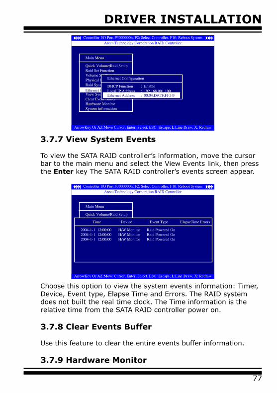
DRIVER INSTALLATION
77
3.7.7 View System Events
To view the SATA RAID controller’s information, move the cursor bar to the main menu and select the View Events link, then press the Enter key The SATA RAID controller’s events screen appear.
Choose this option to view the system events information: Timer, Device, Event type, Elapse Time and Errors. The RAID system does not built the real time clock. The Time information is the relative time from the SATA RAID controller power on.
3.7.8 Clear Events Buffer
Use this feature to clear the entire events buffer information.
3.7.9 Hardware Monitor
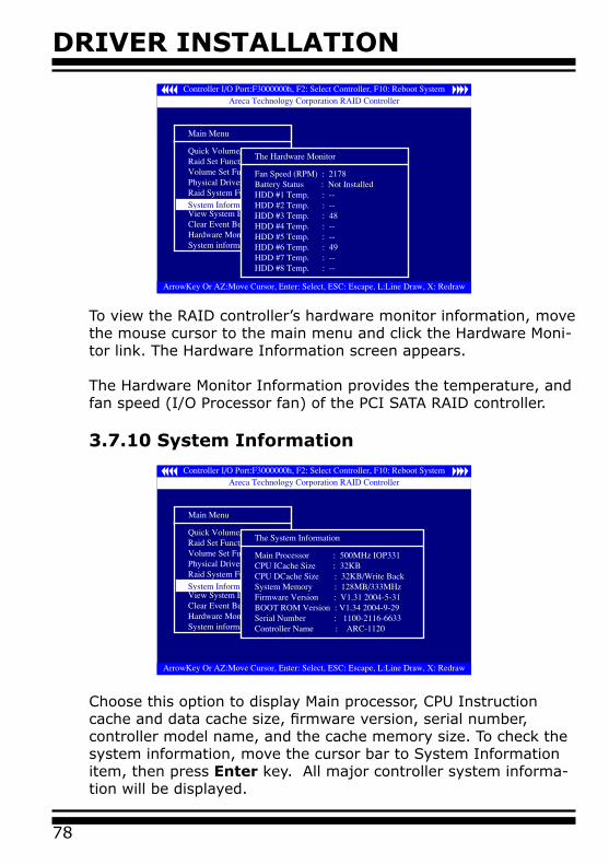
DRIVER INSTALLATION
78
To view the RAID controller’s hardware monitor information, move the mouse cursor to the main menu and click the Hardware Moni-tor link. The Hardware Information screen appears.
The Hardware Monitor Information provides the temperature, and fan speed (I/O Processor fan) of the PCI SATA RAID controller.
3.7.10 System Information
Choose this option to display Main processor, CPU Instruction cache and data cache size, firmware version, serial number, controller model name, and the cache memory size. To check the system information, move the cursor bar to System Information item, then press Enter key. All major controller system informa-tion will be displayed.
DRIVER INSTALLATION
79
4. Driver InstallationThis chapter describes how to install the SATA RAID controller drive to your operating system. The installation procedures depend on the fol-lowing terminology:
Installing operating system on the SATA Volume
If you have a new drive configuration without an operating system and want to install operating system on a disk drive managed by the SATA RAID Controller. The driver installation is a part of the operat-ing system installation.
Installing SATA RAID controller into an existing operating system
The computer has an existing operating system installed and the SATA RAID controller is being installed as a secondary controller.
Have all required system hardware and software component on hand before proceeding with the setup and installationMaterials required:
• Microsoft Windows 2000/XP/2003, or Linux, and or FreeBSD instal-lation CD-ROM• SATA RAID Controller Diver CD-ROM• SATA RAID controller
4.1 Creating the Driver Diskettes
The SATA RAID controller shipped with CD-ROM disc is a self-boot-ing CD. In order to created driver diskettes for Windows, Linux, and FreeBSD installation drivers. Your system required to supports bootable from CD-ROM.
If you do not have the CD-ROM disc with the package, contact your local dealer or you can also download the latest version drivers for Windows 2000/XP/2003, Linux, and freeBSD from the ARECA web site at http://www.areca.com.tw .
The following steps is creating the Driver diskettes:
DRIVER INSTALLATION
80
1. The computer system BIOS must set to boot-up from CD-ROM.
2. Insert the SATA Controller Driver CD disc into the CD-ROM drive.
3. System will boot-up from CD-ROM Drive, to create the driver diskettes selected the “SATA RAID controller Driver Diskette Make Utility”, and provides several screens with choices.
4. Move the highlight bar to the “Create Driver Disk” entry and press Enter.
5. The screen queries the SATA RAID controller support driver da-tabase and a list of supported driver is displayed. Move the high-light bar to the driver entry and press Enter for moving forward.
6. The next screen will show “Please insert a formatted dis-kette into drive A:!! Press any key to continue”. Insert the formatted diskette in drive “A” and press any key to continue.
7. The window will displays the driver building message: ”Now is writing to Cylinder…” and copy the image file from the CD-ROM to Driver Diskette.
8. The “Write Complete !!” message will show at the screen when the driver is build ready.
The driver diskette is now made. Proceed to the following instruc-tion for installation procedures.
4.2 Driver Installation for Windows
SATA RAID controller can be used with Microsoft Windows 2000, Windows XP, and Windows Server 2003. Windows 2003 64-bit for AMD Opteron is also supported. SATA RAID controllers supports SCSI Miniport and StorPort Drivers for Windows Server 2003.
4.2.1 New Storage Device Drivers in Windows Server 2003
The Storport driver is new to Windows Server 2003. Storport im-plements a new architecture designed for better performance for
DRIVER INSTALLATION
81
RAID systems and in Storage Area Network (SAN) environments. Storport delivers higher I/O throughput, enhanced manageability, and an improved miniport interface. Storport better utilizes faster adapters through the use of reduced Delay Procedure Call (DPC) and improved queue management.
4.2.2 Install Windows 2000/XP/2003 on a SATA RAID Volume
The following instructions explain how to install the SATA RAID controller Driver. For completed details on installing Windows, see the Windows User’s Manual.
4.2.2.1 Installation procedures
The following is the procedures for installing the SATA RAID con-troller driver while installing Windows 2000/XP/2003. Boot-up Microsoft Windows 2000/XP/2003 from CD-ROM and follow the required procedure below to install SATA RAID con-troller:
1. Make sure you follow the instructions in Chapter 2 “Hard-ware Installation” to install the controller and connect the disk drives or enclosure.
2. Start the system and then press Tab/F6 to enable the McBIOS RAID manager. Use the McBIOS manager to create the RAID set and volume set to which you will install Windows system. For details, see Chapter 3 “McBIOS RAID manager”. Once a volume set is created and configured, continue with next step to install the operating system.
3. Insert Windows setup CD and restart the system to begin the Windows installation.
Note:
The computer system BIOS must support bootable from CD-ROM.
DRIVER INSTALLATION
82
4. Press F6 when the screen shows ”Setup is inspecting your Computer’s hardware Configuration”. This must be done or else the new driver installed from the SATA RAID driver diskette will not be recognized.
5. The next screen will show: “Setup could not determine the type of one or more mass storage device installed in your system.” Selected specify additional SCSI adapter by pressing S.
6. Window will prompt for the “Manufacturer-supplied hard-ware support disk” into floppy drive A: Insert the SATA RAID series driver diskette in drive “A:” and press Enter.
7. Window will check the floppy and select the correct drive and CPU type in the listing that you want to install and press Enter to install it.
8. After Windows scans the hardware and finds the controller, it will display:“Setup will load support for the following Mass Storage devices:”“Windows 2K, XP,2K3 (ARC1XX0) SATA PCI-X (or PCI-Ex-press) RAID Controller”. Press Enter to continue and copy the driver files.At this point, simply follow the Microsoft Windows installation procedure.Follow the on-screen instructions, responding as needed to com-plete the installation.
9. After the installation is completed, reboot the system to load the new drivers.
10. See Chapter 5 in this manual to customize your RAID vol-ume sets using Storage manager.
4.2.2.2 Making Volume Sets Available to Windows System
When you reboot the system, log in as system administrator. Continue with the following steps to make any new volume sets
DRIVER INSTALLATION
83
or pass-through disks accessible to Windows. This procedure assumes that the SATA RAID controller hardware, driver, and Windows are installed and operational in your system.
1. Partition and format the new volume set or disks using Disk Administrator:
a. Choose Administrative Tools from the Start menu.b. Choose Computer Management from the Administrative Tools menu.c. Select Storage.d. Select Disk Management.
2. Follow the on-screen prompts to write a signature to the drive.
3. Right click on the disk drive and select Create Volume from the menu.
4. Follow the on-screen prompts to create a volume set and to give a disk drive letter.
4.2.3 Install controller into an existing Windows 2000/XP/2003
In this scenario, you are installing the controller in a new Win-dows system. To install the driver:
1. Follow the instructions in Chapter 2 Hardware Installation Chapter to install the controller and connect the disk drives or enclosure.
2. Start the system and then press Tab/F6 to enter the McBIOS-based configuration utility. Use the configuration utility to create the raid set and volume set. For details, see Chapter 3 McBIOS RAID Manager. Once a volume set is created and configured, continue with install the driver.
3. Re-Boot Windows and OS will recognizes the SATA RAID Controller and launches the “Found New Hardware Wizard”, which guides you in installing the SATA RAID driver.
DRIVER INSTALLATION
84
4. The “Upgrade Device Driver Wizard” popup and provides a choice for the wizard to select. Choose “Display a list of known drivers for this device, so that you can choose a specific driver.” and click on Next.
5. When the next screen queries the user about utilizing the cur-rently installed driver, click on Have Disk button.
6. When the “Install From Disk” dialog appears, insert the SATA RAID controller driver diskette or the ship CD-ROM and type the correct path name in the “Copy manufacturer’s files from:”
7. The previous dialog box appears with the selected driver dis-played as of the driver to install. Then click on Next. 8. The “Digital Signature Not Found” screen appears. Click on Yes to continue the installation.
9. Windows automatically copies the appropriate driver files and rebuilds its driver database.
10. The “Found New Hardware Wizard” summary screen ap-pears Click on the Finish button.
11. The “System Settings Change” dialog box appears. Re-move the diskette from the drive and click on Yes to restart the computer to load the new drivers.
12. See Chapter 5 in this manual to customize your RAID vol-umes using Storage manager.
4.2.3.1 Making Volume Sets Available to Windows System
When you reboot the system, log in as system administrator. Continue with the following steps to make any new disk arrays or independent disks accessible to Windows 2000/XP/2003. This procedure assumes that the SATA RAID controller hardware, driver, and Windows are installed and operational in your sys-tem.
DRIVER INSTALLATION
85
1. Partition and format the new arrays or disks using Disk Ad-ministrator:
a. Choose Administrative Tools from the Start menu.b. Choose Computer Management from the Administrative Tools menu.c. Select Storage.d. Select Disk Management.
2. Follow the on-screen prompts to write a signature to the drive.
3. Right click on the drive and select Create Volume from the menu.
4. Follow the on-screen prompts to create a volume set and to give a disk drive letter.
4.2.4 Uninstall controller from Windows 2000/XP/2003
To remove the SATA RAID controller driver from the Windows sys-tem follow the instructions below.
1. Ensure that you have closed all applications and are logged in with administrative rights.
2. Open Control Panel and start the Add/Remove Program icon.
3. Select the SATA RAID controller driver and click on OK.
4. Click on Yes to confirm removing the SATA RAID driver. The Uninstall shield program will start removing files and display a progress bar. After the programs have been completely re-moved from your system, the uninstall shield program will show a summary of files removed and updates completed while re-moving files from the system. It will also recommend that the user restart the system.
DRIVER INSTALLATION
86
4.3 Driver Installation for Linux
This chapter describes how to install the SATA RAID controller drive to your Red Hat Linux, and SuSE Linux. Before installing the SATA RAID driver to the Linux, you must have done the following action:
1. Install and configure the controller and hard disk drives accord-ing to the instructions in Chapter 2 Hardware Installation.
2. Start the system and then press Tab/F6 to enter the McBIOS RAID manager configuration utility. Use the BIOS configuration utility to create the raid set and volume set. For details, see Chap-ter 3 McBIOS RAID Manager.If you are using a Linux distribution for which there is not a com-piled driver available from ARECA, you can copy the source from the SATA software CD or download the source from the ARECA website and compile a new driver. Compiled and tested drivers for Red Hat and SuSE Linux are includ-ed on the ship CD. You can download the updated version compiled and tested driver for Red Hat or SuSE Linux from the ARECA web site at http://www.areca.com.tw. Included in these downloads is the Linux driver source, which you can use to compile the updated version driver for RedHat, SuSE, and other versions of Linux. Please refer to the “readme.txt” file on the ARECA ship CD-ROM or website to make driver diskette and to install driver to the sys-tem.
4.4 Driver Installation for FreeBSD
This chapter describes how to install the SATA RAID controller drive to your FreeBSD.Before installing the SATA RAID driver to the FreeBSD, you must do the following action:
1. Install and configure the controller and hard disk drives accord-ing to the instructions in Chapter 2 Hardware Installation
2. Start the system and then press Tab/F6 to enter the McBIOS RAID Manager configuration utility. Use the BIOS configuration utility to create the raid set and volume set. For details, see Chap-
DRIVER INSTALLATION
87
ter 3 McBIOS RAID Manager.The ship CD-ROM that came with the SATA RAID controller includes compiled and tested drivers for FreeBSD 4.x (4.2 and onwards) and 5.x (5.2 and onwards). To check if a more updated version driver is available, please see the ARECA web site http://www.areca.com.tw.
Please refer to the “readme.txt” file on the SATA RAID controller software CD-ROM or website to make driver diskette and to install driver to the system.
INSTALLATION ARCHTTP PROXY SERVER
88
5. Installation ArcHttp Proxy ServerOverview
After the hardware installation, the SATA disk drives connected to the SATA RAID controller must be configured and the volume set units ini-tialized before they are ready to use. Those user interfaces can access the built-in configuration and admin-istration utility that resides in the controller’s firmware. They provide complete control and management of the controller and disk arrays, eliminating the need for additional hardware or software.The software utility refers to SATA RAID controller software on the CD-ROM delivered with your system. This CD-ROM contains the software utility that is required for the monitor, test, and support of SATA RAID controller. The software utility and McRAID storage manager can con-figure and monitor the SATA RAID controller via ArcHttp Proxy Server. The following table outlines their functions:
5.1 For Windows
You must have administrative level permission to install SATA RAID software. This procedure assumes that the SATA RAID hardware and windows are installed and operational in your system.Screen in this section are taken from a Windows/XP installation. If you are running other Windows, your installing screen may look different, but the ArcHttp proxy server installation is essentially the same.
1. Insert the RAID subsystem CD in the CD-ROM drive.2. Run the setup.exe file that resides at: <CD-ROM>\windows\http\setup.exe on the CD-ROM.
Configuration Utility Operating System supported
McBIOS RAID Manager OS-Independent
McRAID Storage Manager(Via Archttp proxy server)
Windows 2000/XP/2003, Linux and FreeBSD
SAP Monitor(Single Admin portal to scan for mul-tiple RAID units in the network, Via
ArcHttp Proxy Server)
Windows 2000/XP/2003Java based for Windows.Linux and FreeBSD (available in Q2, 2005)
SNMP Manager Console Integration(Via ArcHttp Proxy Server)
Windows 2000/XP/2003, Linux. FreeBSD (available in Q2, 2005)
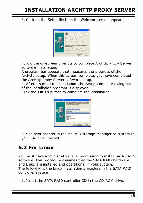
89
INSTALLATION ARCHTTP PROXY SERVER
3. Click on the Setup file then the Welcome screen appears.
Follow the on-screen prompts to complete ArcHttp Proxy Server software installation.A program bar appears that measures the progress of the ArcHttp setup. When this screen complete, you have completed the ArcHttp Proxy Server software setup.4. After a successful installation, the Setup Complete dialog box of the installation program is displayed.Click the Finish button to complete the installation.
5. See next chapter in the McRAID storage manager to customize your RAID volume set.
5.2 For Linux
You must have administrative level permission to install SATA RAID software. This procedure assumes that the SATA RAID hardware and Linux are installed and operational in your system.The following is the Linux installation procedure in the SATA RAID controller system.
1. Insert the SATA RAID controller CD in the CD-ROM drive.
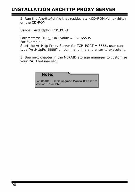
INSTALLATION ARCHTTP PROXY SERVER
90
2. Run the ArcHttpPci file that resides at: <CD-ROM>\linux\http\ on the CD-ROM.
Usage: ArcHttpPci TCP_PORT Parameters: TCP_PORT value = 1 ~ 65535For Example:Start the ArcHttp Proxy Server for TCP_PORT = 6666, user can type “ArcHttpPci 6666” on command line and enter to execute it.
3. See next chapter in the McRAID storage manager to customize your RAID volume set.
Note:
For RedHat Users: upgrade Mozilla Browser to Version 1.6 or later.
91
WEB BROWSER-BASED CONFIGURATION
6. Web Browser-based Configuration
Before using the McRAID firmware-based browser utility, do the initial setup and installation of this product. If you need to boot up the op-erating system from a RAID volume set, you must first create a RAID volume by using McBIOS RAID Manager. Please refer to section 3.3 Using Quick Volume /Raid Setup Configuration for information on creating this initial volume set.
The McRAID manager is firmware-based utility, which utilizes the browser installed on your operating system. The McRAID Manager program is an HTML-based application, which utilizes the browser (IE, Netscape and Mozilla etc) installed on your monitor station. It allows user through web browser to create and modify RAID set, volume set, and monitor SATA RAID Controller status. Use this utility to:
• Create raid set• Expand raid set• Define volume set• Add physical drive • Modify volume set• Modify RAID level/stripe size• Define pass-through disk drives• Modify system function• Update firmware• Designate drives as hot spares
6.1 Start-up McRAID Manager for Local Ad-ministration
With McRAID Storage Manager, you can Local manage a system containing a SATA RAID controller that has Windows or Linux and a supported browser.A locally managed system requires all of the following compo-nents:
• A supported Web browser, which should already be installed on the system.• Installing an ArcHttp proxy server on the SATA RAID system.
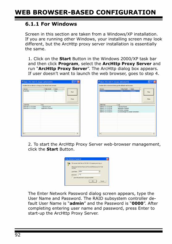
WEB BROWSER-BASED CONFIGURATION
92
6.1.1 For Windows
Screen in this section are taken from a Windows/XP installation. If you are running other Windows, your installing screen may look different, but the ArcHttp proxy server installation is essentially the same.
1. Click on the Start Button in the Windows 2000/XP task bar and then click Program, select the ArcHttp Proxy Server and run “ArcHttp Proxy Server”. The ArcHttp dialog box appears. If user doesn’t want to launch the web browser, goes to step 4.
2. To start the ArcHttp Proxy Server web-browser management, click the Start Button.
The Enter Network Password dialog screen appears, type the User Name and Password. The RAID subsystem controller de-fault User Name is “admin” and the Password is “0000”. After completing entering user name and password, press Enter to start-up the ArcHttp Proxy Server.
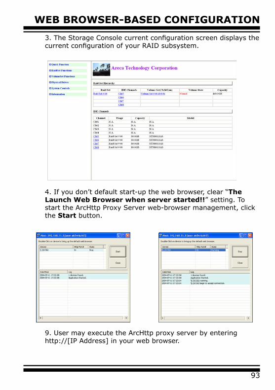
93
WEB BROWSER-BASED CONFIGURATION
3. The Storage Console current configuration screen displays the current configuration of your RAID subsystem.
4. If you don’t default start-up the web browser, clear “The Launch Web Browser when server started!!” setting. To start the ArcHttp Proxy Server web-browser management, click the Start button.
9. User may execute the ArcHttp proxy server by entering http://[IP Address] in your web browser.
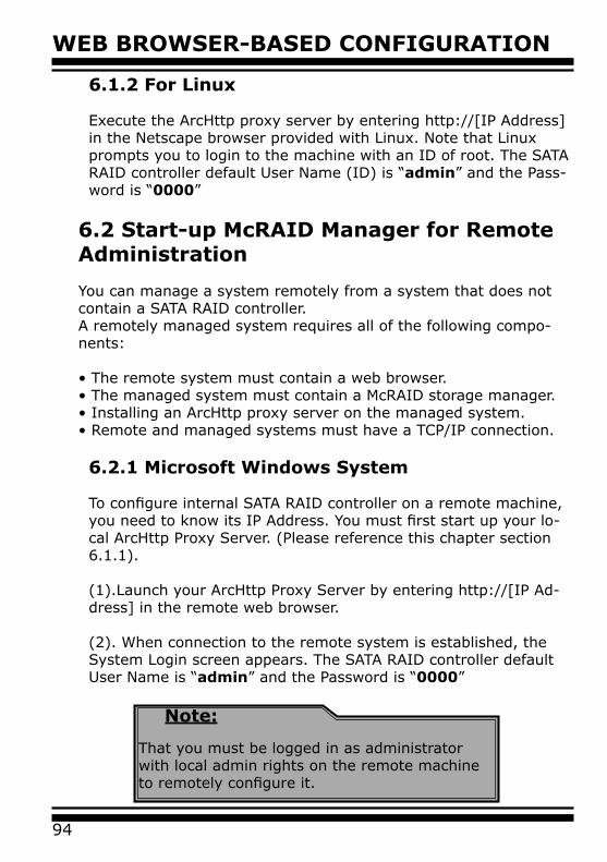
WEB BROWSER-BASED CONFIGURATION
94
6.1.2 For Linux
Execute the ArcHttp proxy server by entering http://[IP Address] in the Netscape browser provided with Linux. Note that Linux prompts you to login to the machine with an ID of root. The SATA RAID controller default User Name (ID) is “admin” and the Pass-word is “0000”
6.2 Start-up McRAID Manager for Remote Administration
You can manage a system remotely from a system that does not contain a SATA RAID controller.A remotely managed system requires all of the following compo-nents:
• The remote system must contain a web browser.• The managed system must contain a McRAID storage manager.• Installing an ArcHttp proxy server on the managed system.• Remote and managed systems must have a TCP/IP connection.
6.2.1 Microsoft Windows System
To configure internal SATA RAID controller on a remote machine, you need to know its IP Address. You must first start up your lo-cal ArcHttp Proxy Server. (Please reference this chapter section 6.1.1).
(1).Launch your ArcHttp Proxy Server by entering http://[IP Ad-dress] in the remote web browser.
(2). When connection to the remote system is established, the System Login screen appears. The SATA RAID controller default User Name is “admin” and the Password is “0000”
Note:
That you must be logged in as administrator with local admin rights on the remote machine to remotely configure it.
95
WEB BROWSER-BASED CONFIGURATION
6.2.2 Linux System
To configure SATA RAID controller on a remote machine, you need to know its IP Address. You must first start up your local ArcHttp proxy server. (Please reference this chapter section 6.1.1).
(1).Launch your ArcHttp proxy server by entering http://[IP Ad-dress] in the remote web browser.
(2). When connection to the remote system is established, the System Login screen appears. The SATA RAID controller default User Name is “admin” and the Password is “0000”
6.3 SATA RAID controller McRAID storage manager
The McRAID storage manager current configuration screen displays the current configuration of your SATA RAID controller. It displays the Raid Set List, Volume Set List and Physical Disk List. The raid set information, volume set information and drive information can also be viewed by clicking on the RaidSet Hierarchy screen. The current configuration can also be viewed by clicking on RaidSet Hierarchy in the menu.
Note:
That you must be logged in as administrator with local admin rights on the remote machine to remotely configure it.
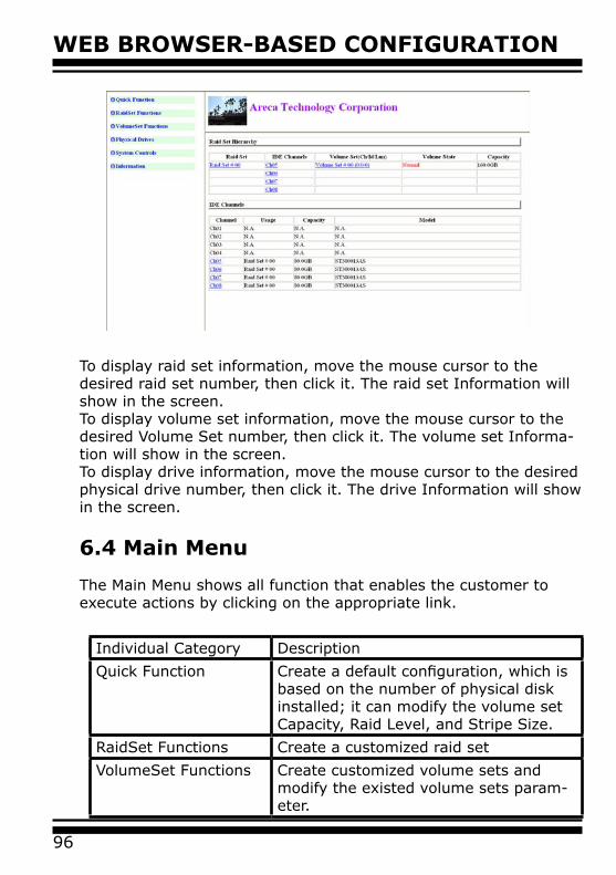
WEB BROWSER-BASED CONFIGURATION
96
To display raid set information, move the mouse cursor to the desired raid set number, then click it. The raid set Information will show in the screen. To display volume set information, move the mouse cursor to the desired Volume Set number, then click it. The volume set Informa-tion will show in the screen. To display drive information, move the mouse cursor to the desired physical drive number, then click it. The drive Information will show in the screen.
6.4 Main Menu
The Main Menu shows all function that enables the customer to execute actions by clicking on the appropriate link.
Individual Category Description
Quick Function Create a default configuration, which is based on the number of physical disk installed; it can modify the volume set Capacity, Raid Level, and Stripe Size.
RaidSet Functions Create a customized raid set
VolumeSet Functions Create customized volume sets and modify the existed volume sets param-eter.
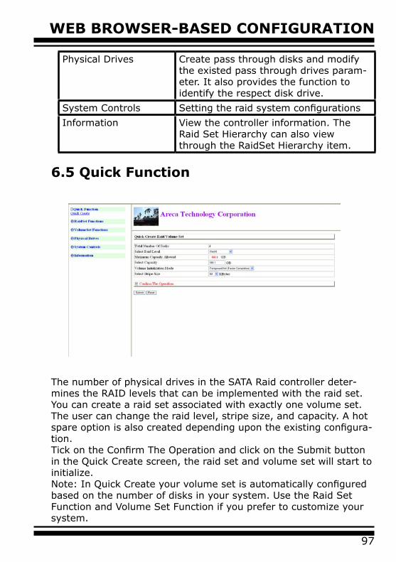
97
WEB BROWSER-BASED CONFIGURATION
6.5 Quick Function
The number of physical drives in the SATA Raid controller deter-mines the RAID levels that can be implemented with the raid set. You can create a raid set associated with exactly one volume set. The user can change the raid level, stripe size, and capacity. A hot spare option is also created depending upon the existing configura-tion.Tick on the Confirm The Operation and click on the Submit button in the Quick Create screen, the raid set and volume set will start to initialize.Note: In Quick Create your volume set is automatically configured based on the number of disks in your system. Use the Raid Set Function and Volume Set Function if you prefer to customize your system.
Physical Drives Create pass through disks and modify the existed pass through drives param-eter. It also provides the function to identify the respect disk drive.
System Controls Setting the raid system configurations
Information View the controller information. The Raid Set Hierarchy can also view through the RaidSet Hierarchy item.
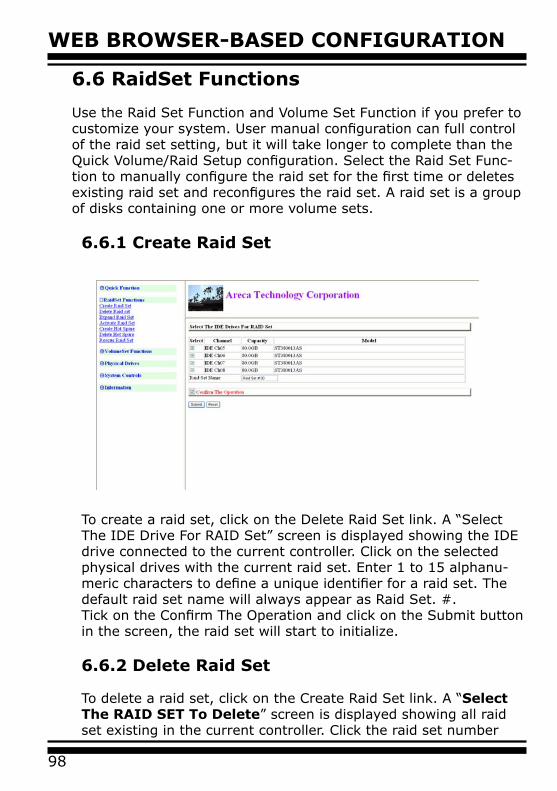
WEB BROWSER-BASED CONFIGURATION
98
6.6 RaidSet Functions
Use the Raid Set Function and Volume Set Function if you prefer to customize your system. User manual configuration can full control of the raid set setting, but it will take longer to complete than the Quick Volume/Raid Setup configuration. Select the Raid Set Func-tion to manually configure the raid set for the first time or deletes existing raid set and reconfigures the raid set. A raid set is a group of disks containing one or more volume sets.
6.6.1 Create Raid Set
To create a raid set, click on the Delete Raid Set link. A “Select The IDE Drive For RAID Set” screen is displayed showing the IDE drive connected to the current controller. Click on the selected physical drives with the current raid set. Enter 1 to 15 alphanu-meric characters to define a unique identifier for a raid set. The default raid set name will always appear as Raid Set. #.Tick on the Confirm The Operation and click on the Submit button in the screen, the raid set will start to initialize.
6.6.2 Delete Raid Set
To delete a raid set, click on the Create Raid Set link. A “Select The RAID SET To Delete” screen is displayed showing all raid set existing in the current controller. Click the raid set number
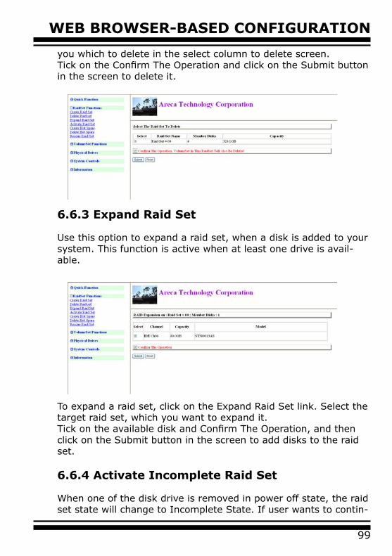
99
WEB BROWSER-BASED CONFIGURATION
you which to delete in the select column to delete screen. Tick on the Confirm The Operation and click on the Submit button in the screen to delete it.
6.6.3 Expand Raid Set
Use this option to expand a raid set, when a disk is added to your system. This function is active when at least one drive is avail-able.
To expand a raid set, click on the Expand Raid Set link. Select the target raid set, which you want to expand it.Tick on the available disk and Confirm The Operation, and then click on the Submit button in the screen to add disks to the raid set.
6.6.4 Activate Incomplete Raid Set
When one of the disk drive is removed in power off state, the raid set state will change to Incomplete State. If user wants to contin-
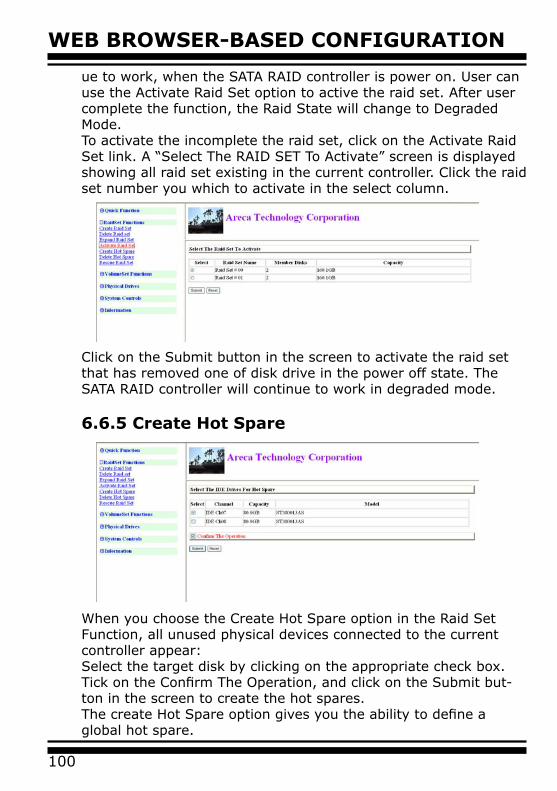
WEB BROWSER-BASED CONFIGURATION
100
ue to work, when the SATA RAID controller is power on. User can use the Activate Raid Set option to active the raid set. After user complete the function, the Raid State will change to Degraded Mode.To activate the incomplete the raid set, click on the Activate Raid Set link. A “Select The RAID SET To Activate” screen is displayed showing all raid set existing in the current controller. Click the raid set number you which to activate in the select column.
Click on the Submit button in the screen to activate the raid set that has removed one of disk drive in the power off state. The SATA RAID controller will continue to work in degraded mode.
6.6.5 Create Hot Spare
When you choose the Create Hot Spare option in the Raid Set Function, all unused physical devices connected to the current controller appear: Select the target disk by clicking on the appropriate check box. Tick on the Confirm The Operation, and click on the Submit but-ton in the screen to create the hot spares.The create Hot Spare option gives you the ability to define a global hot spare.
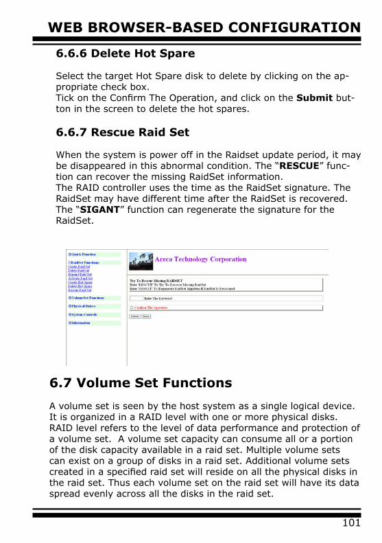
101
WEB BROWSER-BASED CONFIGURATION
6.7 Volume Set Functions
A volume set is seen by the host system as a single logical device. It is organized in a RAID level with one or more physical disks. RAID level refers to the level of data performance and protection of a volume set. A volume set capacity can consume all or a portion of the disk capacity available in a raid set. Multiple volume sets can exist on a group of disks in a raid set. Additional volume sets created in a specified raid set will reside on all the physical disks in the raid set. Thus each volume set on the raid set will have its data spread evenly across all the disks in the raid set.
6.6.6 Delete Hot Spare
Select the target Hot Spare disk to delete by clicking on the ap-propriate check box.Tick on the Confirm The Operation, and click on the Submit but-ton in the screen to delete the hot spares.
6.6.7 Rescue Raid Set
When the system is power off in the Raidset update period, it may be disappeared in this abnormal condition. The “RESCUE” func-tion can recover the missing RaidSet information.The RAID controller uses the time as the RaidSet signature. The RaidSet may have different time after the RaidSet is recovered. The “SIGANT” function can regenerate the signature for the RaidSet.
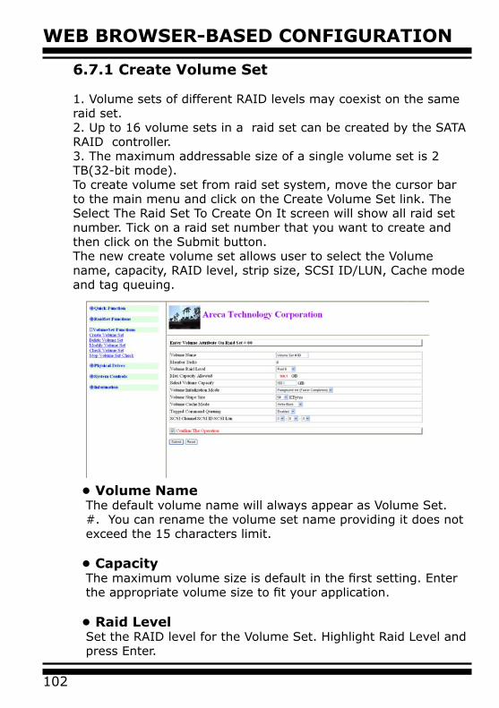
WEB BROWSER-BASED CONFIGURATION
102
6.7.1 Create Volume Set
1. Volume sets of different RAID levels may coexist on the same raid set.2. Up to 16 volume sets in a raid set can be created by the SATA RAID controller.3. The maximum addressable size of a single volume set is 2 TB(32-bit mode).To create volume set from raid set system, move the cursor bar to the main menu and click on the Create Volume Set link. The Select The Raid Set To Create On It screen will show all raid set number. Tick on a raid set number that you want to create and then click on the Submit button.The new create volume set allows user to select the Volume name, capacity, RAID level, strip size, SCSI ID/LUN, Cache mode and tag queuing.
• Volume NameThe default volume name will always appear as Volume Set. #. You can rename the volume set name providing it does not exceed the 15 characters limit.
• CapacityThe maximum volume size is default in the first setting. Enter the appropriate volume size to fit your application.
• Raid Level Set the RAID level for the Volume Set. Highlight Raid Level and press Enter.
103
WEB BROWSER-BASED CONFIGURATION
The available RAID levels for the current Volume Set are dis-played. Select a RAID level and press Enter to confirm.
• Strip SizeThis parameter sets the size of the stripe written to each disk in a RAID 0, 1, (10), 5 or 6 logical drive. You can set the stripe size to 4 KB, 8 KB, 16 KB, 32 KB, 64 KB, or 128 KB.A larger stripe size produces better-read performance, espe-cially if your computer does mostly sequential reads. However, if you are sure that your computer does random reads more often, select a small stripe sizeNote: RAID level 3 can’t modify strip size.
• Cache ModeThe SATA RAID controller supports Write-Through Cache and Write-Back Cache.
• SCSI Channel/SCSI ID/SCSI LunSCSI Channel: The SATA RAID controller function is simulated to the SCSI RAID controller. The host bus is represented to the SCSI channel. Choose the SCSI Channel. SCSI ID: Each SCSI device attached to the SCSI card, as well as the card itself, must be assigned a unique SCSI ID number. A SCSI channel can connect up to 15 devices. The SATA RAID controller is as a lots of large SCSI device. We should assign an ID from a list of SCSI IDs. SCSI LUN: Each SCSI ID can support up to 8 LUNs. Most SCSI controller treats each LUN like a SCSI disk.
• Tag QueuingThe Enabled option is useful for enhancing overall system performance under multi-tasking operating systems. The Com-mand Tag (Drive Channel) function controls the SCSI com-mand tag queuing support for each drive channel. This func-tion should normally remain enabled. Disable this function only when using older SCSI drives that do not support command tag queuing
6.7.2 Delete Volume Set
To delete Volume from raid set system function, move the cursor
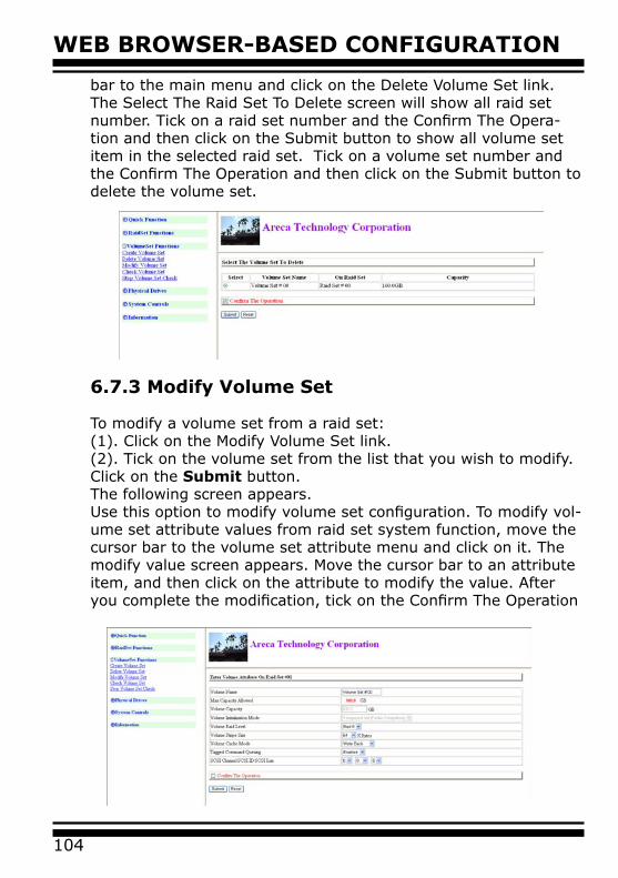
WEB BROWSER-BASED CONFIGURATION
104
bar to the main menu and click on the Delete Volume Set link. The Select The Raid Set To Delete screen will show all raid set number. Tick on a raid set number and the Confirm The Opera-tion and then click on the Submit button to show all volume set item in the selected raid set. Tick on a volume set number and the Confirm The Operation and then click on the Submit button to delete the volume set.
6.7.3 Modify Volume Set
To modify a volume set from a raid set:(1). Click on the Modify Volume Set link.(2). Tick on the volume set from the list that you wish to modify. Click on the Submit button.The following screen appears.Use this option to modify volume set configuration. To modify vol-ume set attribute values from raid set system function, move the cursor bar to the volume set attribute menu and click on it. The modify value screen appears. Move the cursor bar to an attribute item, and then click on the attribute to modify the value. After you complete the modification, tick on the Confirm The Operation
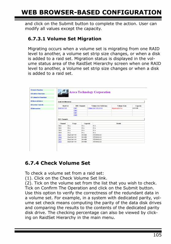
105
WEB BROWSER-BASED CONFIGURATION
and click on the Submit button to complete the action. User can modify all values except the capacity.
6.7.3.1 Volume Set Migration
Migrating occurs when a volume set is migrating from one RAID level to another, a volume set strip size changes, or when a disk is added to a raid set. Migration status is displayed in the vol-ume status area of the RaidSet Hierarchy screen when one RAID level to another, a Volume set strip size changes or when a disk is added to a raid set.
6.7.4 Check Volume Set
To check a volume set from a raid set:(1). Click on the Check Volume Set link.(2). Tick on the volume set from the list that you wish to check. Tick on Confirm The Operation and click on the Submit button.Use this option to verify the correctness of the redundant data in a volume set. For example, in a system with dedicated parity, vol-ume set check means computing the parity of the data disk drives and comparing the results to the contents of the dedicated parity disk drive. The checking percentage can also be viewed by click-ing on RaidSet Hierarchy in the main menu.
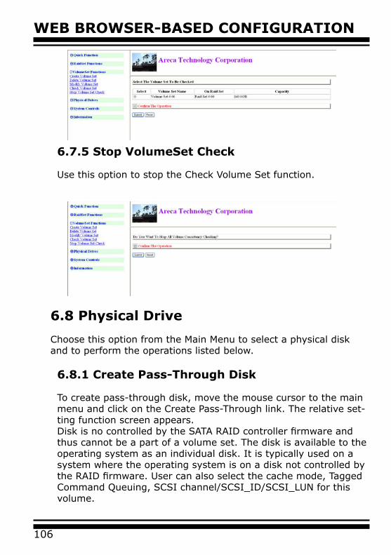
WEB BROWSER-BASED CONFIGURATION
106
6.8 Physical Drive
Choose this option from the Main Menu to select a physical disk and to perform the operations listed below.
6.8.1 Create Pass-Through Disk
To create pass-through disk, move the mouse cursor to the main menu and click on the Create Pass-Through link. The relative set-ting function screen appears.Disk is no controlled by the SATA RAID controller firmware and thus cannot be a part of a volume set. The disk is available to the operating system as an individual disk. It is typically used on a system where the operating system is on a disk not controlled by the RAID firmware. User can also select the cache mode, Tagged Command Queuing, SCSI channel/SCSI_ID/SCSI_LUN for this volume.
6.7.5 Stop VolumeSet Check
Use this option to stop the Check Volume Set function.
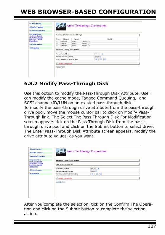
107
WEB BROWSER-BASED CONFIGURATION
6.8.2 Modify Pass-Through Disk
Use this option to modify the Pass-Through Disk Attribute. User can modify the cache mode, Tagged Command Queuing, and SCSI channel/ID/LUN on an existed pass through disk.To modify the pass-through drive attribute from the pass-through drive pool, move the mouse cursor bar to click on Modify Pass-Through link. The Select The Pass Through Disk For Modification screen appears tick on the Pass-Through Disk from the pass-through drive pool and click on the Submit button to select drive.The Enter Pass-Through Disk Attribute screen appears, modify the drive attribute values, as you want.
After you complete the selection, tick on the Confirm The Opera-tion and click on the Submit button to complete the selection action.
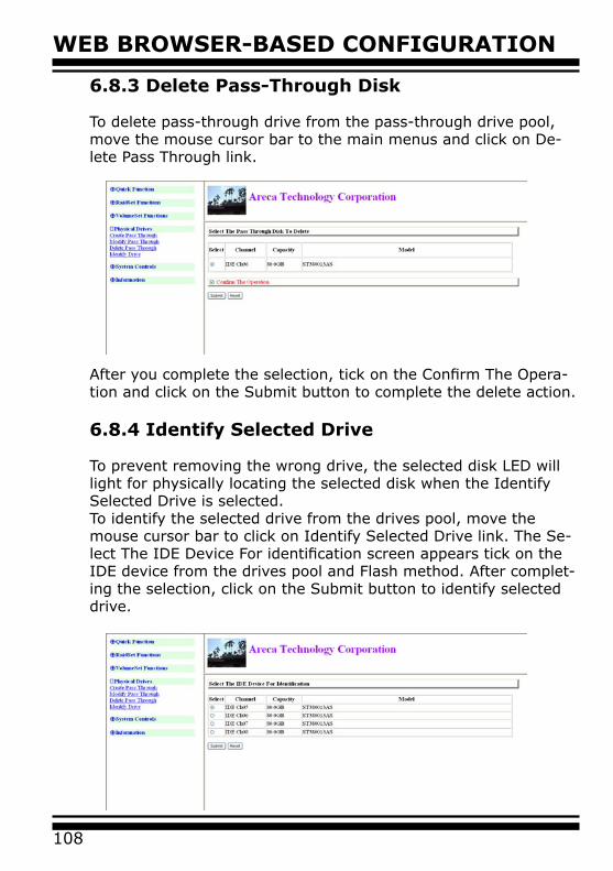
WEB BROWSER-BASED CONFIGURATION
108
6.8.3 Delete Pass-Through Disk
To delete pass-through drive from the pass-through drive pool, move the mouse cursor bar to the main menus and click on De-lete Pass Through link.
After you complete the selection, tick on the Confirm The Opera-tion and click on the Submit button to complete the delete action.
6.8.4 Identify Selected Drive
To prevent removing the wrong drive, the selected disk LED will light for physically locating the selected disk when the Identify Selected Drive is selected. To identify the selected drive from the drives pool, move the mouse cursor bar to click on Identify Selected Drive link. The Se-lect The IDE Device For identification screen appears tick on the IDE device from the drives pool and Flash method. After complet-ing the selection, click on the Submit button to identify selected drive.
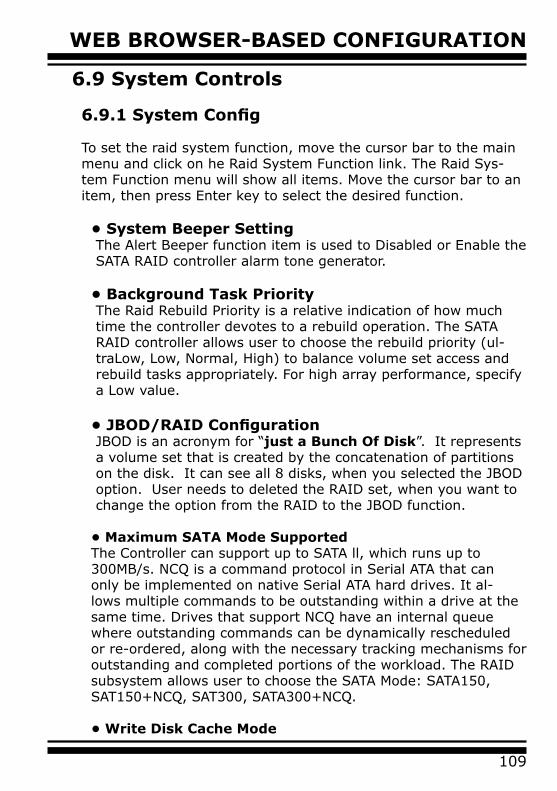
109
WEB BROWSER-BASED CONFIGURATION
6.9 System Controls
6.9.1 System Config
To set the raid system function, move the cursor bar to the main menu and click on he Raid System Function link. The Raid Sys-tem Function menu will show all items. Move the cursor bar to an item, then press Enter key to select the desired function.
• System Beeper SettingThe Alert Beeper function item is used to Disabled or Enable the SATA RAID controller alarm tone generator.
• Background Task PriorityThe Raid Rebuild Priority is a relative indication of how much time the controller devotes to a rebuild operation. The SATA RAID controller allows user to choose the rebuild priority (ul-traLow, Low, Normal, High) to balance volume set access and rebuild tasks appropriately. For high array performance, specify a Low value.
• JBOD/RAID ConfigurationJBOD is an acronym for “just a Bunch Of Disk”. It represents a volume set that is created by the concatenation of partitions on the disk. It can see all 8 disks, when you selected the JBOD option. User needs to deleted the RAID set, when you want to change the option from the RAID to the JBOD function.
• Maximum SATA Mode SupportedThe Controller can support up to SATA ll, which runs up to 300MB/s. NCQ is a command protocol in Serial ATA that can only be implemented on native Serial ATA hard drives. It al-lows multiple commands to be outstanding within a drive at the same time. Drives that support NCQ have an internal queue where outstanding commands can be dynamically rescheduled or re-ordered, along with the necessary tracking mechanisms for outstanding and completed portions of the workload. The RAID subsystem allows user to choose the SATA Mode: SATA150, SAT150+NCQ, SAT300, SATA300+NCQ.
• Write Disk Cache Mode
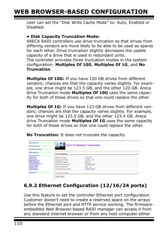
WEB BROWSER-BASED CONFIGURATION
110
6.9.2 Ethernet Configuration (12/16/24 ports)
Use this feature to set the controller Ethernet port configuration. Customer doesn’t need to create a reserved space on the arrays before the Ethernet port and HTTP service working. The firmware-embedded Web Browser-based RAID manager can access it from any standard internet browser or from any host computer either
User can set the “Disk Write Cache Mode” to: Auto, Enabled or Disabled.
• Disk Capacity Truncation Mode:ARECA RAID controllers use drive truncation so that drives from differing vendors are more likely to be able to be used as spares for each other. Drive truncation slightly decreases the usable capacity of a drive that is used in redundant units.The controller provides three truncation modes in the system configuration: Multiples Of 10G, Multiples Of 1G, and No Truncation.
Multiples Of 10G: If you have 120 GB drives from different vendors; chances are that the capacity varies slightly. For exam-ple, one drive might be 123.5 GB, and the other 120 GB. Areca drive Truncation mode Multiples Of 10G uses the same capac-ity for both of these drives so that one could replace the other.
Multiples Of 1G: If you have 123 GB drives from different ven-dors; chances are that the capacity varies slightly. For example, one drive might be 123.5 GB, and the other 123.4 GB. Areca drive Truncation mode Multiples Of 1G uses the same capacity for both of these drives so that one could replace the other.
No Truncation: It does not truncate the capacity.
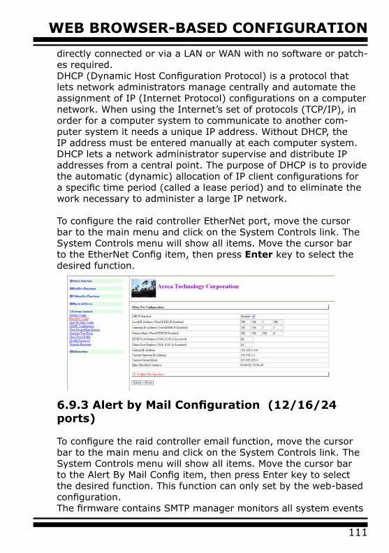
111
WEB BROWSER-BASED CONFIGURATION
directly connected or via a LAN or WAN with no software or patch-es required.DHCP (Dynamic Host Configuration Protocol) is a protocol that lets network administrators manage centrally and automate the assignment of IP (Internet Protocol) configurations on a computer network. When using the Internet’s set of protocols (TCP/IP), in order for a computer system to communicate to another com-puter system it needs a unique IP address. Without DHCP, the IP address must be entered manually at each computer system. DHCP lets a network administrator supervise and distribute IP addresses from a central point. The purpose of DHCP is to provide the automatic (dynamic) allocation of IP client configurations for a specific time period (called a lease period) and to eliminate the work necessary to administer a large IP network.
To configure the raid controller EtherNet port, move the cursor bar to the main menu and click on the System Controls link. The System Controls menu will show all items. Move the cursor bar to the EtherNet Config item, then press Enter key to select the desired function.
6.9.3 Alert by Mail Configuration (12/16/24 ports)
To configure the raid controller email function, move the cursor bar to the main menu and click on the System Controls link. The System Controls menu will show all items. Move the cursor bar to the Alert By Mail Config item, then press Enter key to select the desired function. This function can only set by the web-based configuration.The firmware contains SMTP manager monitors all system events
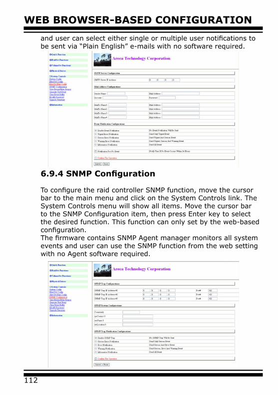
WEB BROWSER-BASED CONFIGURATION
112
and user can select either single or multiple user notifications to be sent via “Plain English” e-mails with no software required.
6.9.4 SNMP Configuration
To configure the raid controller SNMP function, move the cursor bar to the main menu and click on the System Controls link. The System Controls menu will show all items. Move the cursor bar to the SNMP Configuration item, then press Enter key to select the desired function. This function can only set by the web-based configuration.The firmware contains SNMP Agent manager monitors all system events and user can use the SNMP function from the web setting with no Agent software required.
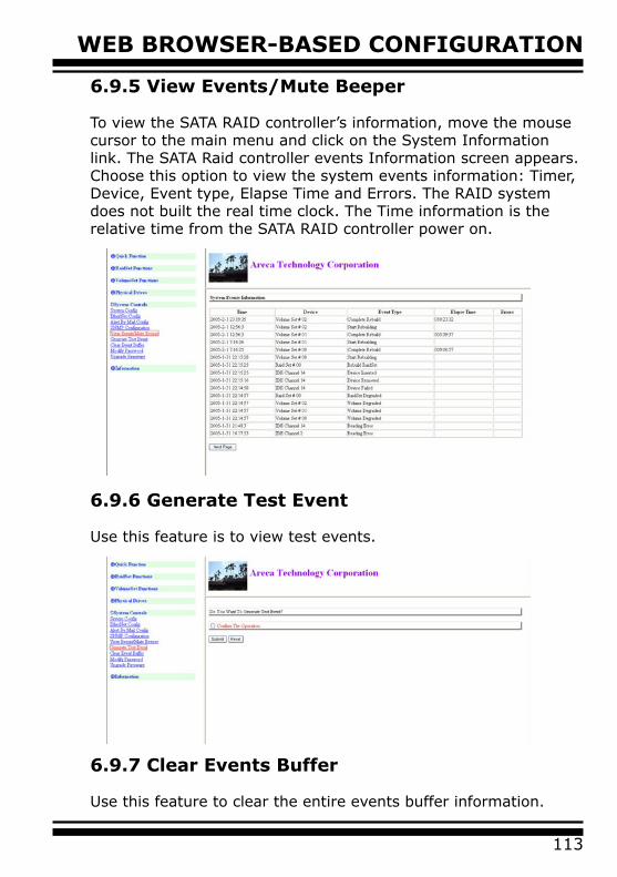
113
WEB BROWSER-BASED CONFIGURATION
6.9.5 View Events/Mute Beeper
To view the SATA RAID controller’s information, move the mouse cursor to the main menu and click on the System Information link. The SATA Raid controller events Information screen appears.Choose this option to view the system events information: Timer, Device, Event type, Elapse Time and Errors. The RAID system does not built the real time clock. The Time information is the relative time from the SATA RAID controller power on.
6.9.6 Generate Test Event
Use this feature is to view test events.
6.9.7 Clear Events Buffer
Use this feature to clear the entire events buffer information.
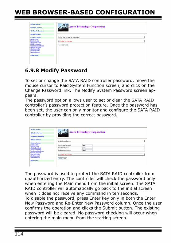
WEB BROWSER-BASED CONFIGURATION
114
6.9.8 Modify Password
To set or change the SATA RAID controller password, move the mouse cursor to Raid System Function screen, and click on the Change Password link. The Modify System Password screen ap-pears.The password option allows user to set or clear the SATA RAID controller’s password protection feature. Once the password has been set, the user can only monitor and configure the SATA RAID controller by providing the correct password.
The password is used to protect the SATA RAID controller from unauthorized entry. The controller will check the password only when entering the Main menu from the initial screen. The SATA RAID controller will automatically go back to the initial screen when it does not receive any command in ten seconds.To disable the password, press Enter key only in both the Enter New Password and Re-Enter New Password column. Once the user confirms the operation and clicks the Submit button. The existing password will be cleared. No password checking will occur when entering the main menu from the starting screen.
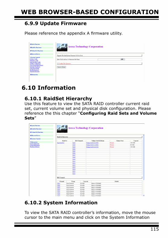
115
WEB BROWSER-BASED CONFIGURATION
6.9.9 Update Firmware
Please reference the appendix A firmware utility.
6.10 Information
6.10.1 RaidSet HierarchyUse this feature to view the SATA RAID controller current raid set, current volume set and physical disk configuration. Please reference the this chapter “Configuring Raid Sets and Volume Sets”
6.10.2 System Information
To view the SATA RAID controller’s information, move the mouse cursor to the main menu and click on the System Information
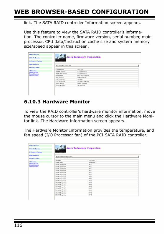
WEB BROWSER-BASED CONFIGURATION
116
link. The SATA RAID controller Information screen appears.
Use this feature to view the SATA RAID controller’s informa-tion. The controller name, firmware version, serial number, main processor, CPU data/Instruction cache size and system memory size/speed appear in this screen.
6.10.3 Hardware Monitor
To view the RAID controller’s hardware monitor information, move the mouse cursor to the main menu and click the Hardware Moni-tor link. The Hardware Information screen appears.
The Hardware Monitor Information provides the temperature, and fan speed (I/O Processor fan) of the PCI SATA RAID controller.
117
APPENDIX
Appendix A Since the SATA RAID controller features flash firmware, it is not necessary to change the hardware flash chip in order to upgrade the RAID firmware. The user can simply re-program the old firm-ware and BIOS through the McRAID storage manager. New releas-es of the Firmware and BIOS are available in the form of a DOS file at web site. The file available at the web site is usually a self-ex-tracting file that contains the following:
1XXXFIRMVVV.BIN Firmware Binary (where “1XXX” refers to the model name and “VVV” refers to the firmware version)1XXXBIOSVVV.BIN BIOS Binary (where “1XXX” refers to the model name and “VVV” refers to the firmware version)README.TXT It contains the history information of the firmware change. Read this file first before upgrading the firmware.These files must be extracted from the compressed file and copied to one directory in drive A: or C:.
Upgrading Firmware Through McRAID Storage Manager
Get the new version firmware for your SATA RAID controller. For Example, download the bin file from your OEM’s web site onto the C:
1. To upgrade the SATA RAID controller firmware, move the mouse cursor to “Upgrade Firmware” link. The “Upgrade The Raid System Firmware” screen appears.
2. Click Browse. Look in the location where the Firmware upgrade software is located. Select the File name click “Open”.
3. Click the “Confirm The Operation” and press the “Submit” button.
4. The Web Browser begins to download the firmware binary to the controller and start to update the flash ROM.
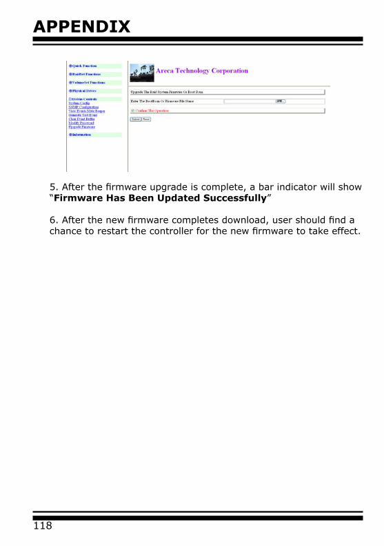
APPENDIX
118
5. After the firmware upgrade is complete, a bar indicator will show “Firmware Has Been Updated Successfully”
6. After the new firmware completes download, user should find a chance to restart the controller for the new firmware to take effect.
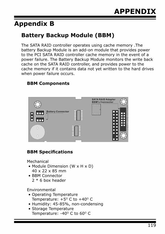
119
APPENDIX
Appendix B
Battery Backup Module (BBM)
The SATA RAID controller operates using cache memory .The battery Backup Module is an add-on module that provides power to the PCI SATA RAID controller cache memory in the event of a power failure. The Battery Backup Module monitors the write back cache on the SATA RAID controller, and provides power to the cache memory if it contains data not yet written to the hard drives when power failure occurs.
BBM Components
BBM Specifications
Mechanical• Module Dimension (W x H x D)
40 x 22 x 85 mm• BBM Connector
2 * 6 box header
Environmental • Operating Temperature
Temperature: +5O C to +40O C• Humidity: 45-85%, non-condensing• Storage Temperature
Temperature: -40O C to 60O C
APPENDIX
120
• Humidity: 45-85%, non-condensingElectrical• Input Voltage
+3.6VDC• On Board Battery Capacity
1000mAH (1*1000mAH)
Installation
1. Make sure all power to the system is disconnected.2. Connector J2 is available for the optional battery backup module. Connect the BBM cable to the 12-pin battery connector on the controller3. Integrators may provide pre-drilled holes in their cabinet for securing the BBM using its three mounting positions.
Battery Backup Capacity
Battery backup capacity is defined as the maximum duration of a power failure for which data in the cache memory can be maintained by the battery. The BBM’s backup capacity varied with the memory chips that installed on the SATA RAID control-ler.
Capacity Memory Type Battery Backup duration (Hours)
128MB DDR Low Power (18mA) 56
Operation
1. Battery conditioning is automatic. There are no manual pro-cedures for battery conditioning or preconditioning to be per-formed by the user.2. Battery bad a tendency to “remember” its capacity. In order to make sure of all the capacity of your battery cells, allow the battery cell to be fully charged when installed for the first time. The first time charge of battery cells takes about 24 hours to complete.
121
APPENDIXChanging the Battery Backup Module
The LI-ION battery will no longer accept a charge properly. LI-ION battery life expectancy is approximately 1 to 5 years.
1. Shutdown the operating system properly. Make sure that cache memory has been flushed.2. Disconnect the battery backup module cable from J2 on the SATA RAID card.3. Disconnect the battery pack cable from JP2 on the Battery Backup Module.4. Install a new battery pack and connect the new battery pack to JP2.5. Connect the Battery Backup Module to J2 on the SATA card.6. Disable the write-back function from the BIOS or Utility.
Note:
The BBM can not work in the mainboard which turn off the PCI-x/pci-exprss clock in the begin-ing stage of power failure.
APPENDIX
122
Appendix C
SNMP Operation & Definition
Overview
The McRAID manager includes a firmware-embedded Simple Net-work Management Protocol (SNMP) agent for the connect SATA RAID controller. An SNMP-based management application (also known as an SNMP manager) can monitor the SATA RAID control-ler. An example of a SNMP management application is Hewlett-Packard’s Open View. The firmware-embedded SNMP agent can be used to augment the SATA RAID controller if you are already run-ning SNMP management application at your site.
SNMP Definition
SNMP, an IP-based protocol, has a set of commands for getting the status of target devices. The SNMP management platform is called the SNMP manager, and the managed devices have the SNMP agent loaded. Management data is organized in a hierarchical data structure called the management Information Base (MIB). These MIBs are defined and sanctioned by various industry associa-tions. The objective is for all vendors to create products in compli-ance with these MIBs so that inter-vendor interoperability can be achieved. If a vendor wishes to include additional device informa-tion that is not specified in a standard MIB, then that is usually done through MIB extensions.
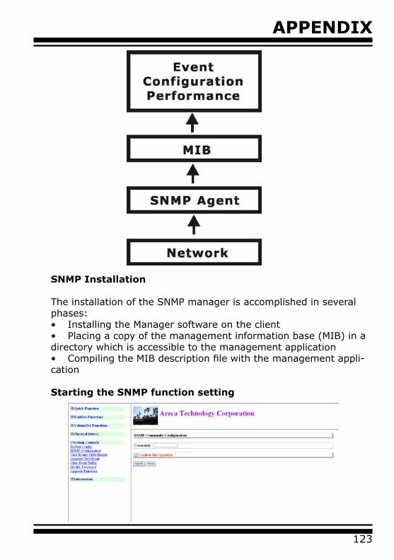
123
APPENDIX
SNMP Installation
The installation of the SNMP manager is accomplished in several phases:• Installing the Manager software on the client• Placing a copy of the management information base (MIB) in a directory which is accessible to the management application• Compiling the MIB description file with the management appli-cation
Starting the SNMP function setting
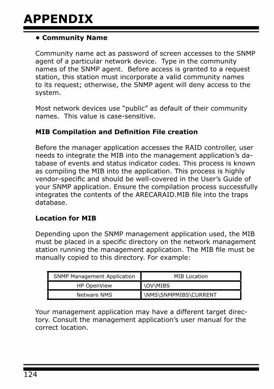
APPENDIX
124
Your management application may have a different target direc-tory. Consult the management application’s user manual for the correct location.
SNMP Management Application MIB Location
HP OpenView \OV\MIBS
Netware NMS \NMS\SNMPMIBS\CURRENT
• Community Name
Community name act as password of screen accesses to the SNMP agent of a particular network device. Type in the community names of the SNMP agent. Before access is granted to a request station, this station must incorporate a valid community names to its request; otherwise, the SNMP agent will deny access to the system.
Most network devices use “public” as default of their community names. This value is case-sensitive.
MIB Compilation and Definition File creation
Before the manager application accesses the RAID controller, user needs to integrate the MIB into the management application’s da-tabase of events and status indicator codes. This process is known as compiling the MIB into the application. This process is highly vendor-specific and should be well-covered in the User’s Guide of your SNMP application. Ensure the compilation process successfully integrates the contents of the ARECARAID.MIB file into the traps database.
Location for MIB
Depending upon the SNMP management application used, the MIB must be placed in a specific directory on the network management station running the management application. The MIB file must be manually copied to this directory. For example:
125
APPENDIX
Appendix D
General Troubleshooting Tips
Most of controller errors are traceable to external factors, such as conflicts with other installed cards, bad or incorrectly configured drives, loose cables, improper controller installation, or other in-stallation errors.
To troubleshoot SATA RAID controller problems, try simplifying your hardware configuration by removing some other devices from the system and then adding them back one at a time.
Look for the latest information on SATA RAID Controllers as well as the newest drivers on the ARECA web site at http://www.areca.com.tw. The following general guidelines are for some specific er-ror conditions:
Question 1: The BIOS Message of the SATA RAID controller never ap-pears on the screen:
Answer:(1). Ensure the controller is inserted correctly into the PCI slot.(2). Ensure 3.3 volts are being supplied to the PCI slot.(3). Check the cabling between the SATA drives or enclosure the SATA RAID controller.
Question 2: How many SATA RAID controllers can be installed into a computer system?
Answer: Up to 4 RAID controllers in a system are supported.
Question 3: The boot device cannot found
Answer: Enter the system BIOS setup utility Per manufacture directions and configure it so that the volume set is once again selected as the
APPENDIX
126
primary boot device (or first in the boot device list)
Question 4: What PCI slots are supported by the SATA RAID controllers?
Answer: For all PCI-X SATA RAID controllers, install card in a 64-bit/133MHz PCI-X for the best performance. It can also be used in 64-bit / 66 MHz slots, 32-bit/66MHz PCI slots as well as 32-bit/33MHz slots.All PCI-X SATA RAID controllers can not work with 5V PCI slot.
Question 5: What is the difference between RAID 6 and RAID 5?
Answer: RAID 6 allows two drives to fail simultaneously without downtime or data loss. However, RAID 5 only allows one drive to fail. RAID 6 thus provides a much higher level of fault tolerance than RAID 5. It is a perfect solution when data is mission-critical.Due to this higher level of protection, users can set up larger RAID volumes, spanning up to 56 physical drives. With ARECA RAID 6 engine. RAID 6 and RAID 5 have similar performance in the SATA RAID controller
Question 6: What products support RAID 6?
Answer: RAID 6 is available with controller model with RAID 6 engine in-stalled
Question 7: What operating systems are supported?
Answer: The SATA RAID controllers support Microsoft® Windows® Server 2003, Windows XP, Windows 2000, Red Hat Linux, SuSE Linux, and FreeBSD. For specific OS versions, see www.areca.com.tw for more information.
127
APPENDIXQuestion 8: Will ARECA submit the Linux code to kernel.org?
Answer: Yes. Shortly after we ship products, we will submit our code.
Question 9: What is the warranty period?
Answer: Like all ARECA External RAID controllers, the PCI-X or PCI-Express SATA RAID controller is backed by a 3-year warranty.
Question 10: Which O/S (Operating System) will support X86 64-bit pro-cessors?
Answer: The following O/S vendors have announced product support for AMD64 and Intel EM64T. Contact each vendor for more details. The following is our currently supported OS and version for 64-bit pro-cessor. We will support others shortly after other versions release.
Microsoft:Production support will be available in:• Windows XP Professional x64 Edition• Windows Server 2003 64-Bit Edition
Red Hat:Production support will be available in:• Red Hat Enterprise Linux 3 update 2
SuSE:Production support will be available in: • SLES9
FreeBSD:Production support will be available in: • FreeBSD 5.3
APPENDIX
128
Question 11: Is it possible to write software that will run on Intel’s pro-cessors with Intel® EM64T, and AMD’s 64-bit capable pro-cessors?
Answer: Yes, in most cases. Even though the hardware microarchitecture for each company’s processor is different, the operating system and software ported to one processor will likely run on the other processor due to the close similarity of the instruction set architec-tures. However, Intel processors support additional features, like the SSE3 instructions and Hyper-Threading Technology, which are not supported on non-Intel platforms. As such, we believe devel-opers will achieve maximum performance and stability by design-ing specifically for Intel architectures and by taking advantage of Intel’s breadth of software tools and enabling services.
Question 12: How will Intel® EM64T work and what software is there to take advantage of 64-bit extensions?
Answer: Platforms with Intel® EM64T/AMD64 can be run in three basic ways (note: a 64-bit capable BIOS is required for all three scenari-os):
1. 32-bit O/S and 32-bit applications (Legacy Mode): No software changes are required, however the user gets no benefit from Intel® EM64T or AMD64;
2. 64-bit O/S and 32-bit applications (Compatibility Mode): This usage requires all 64-bit device drivers. In this mode, the O/S will see the 64-bit extensions, but the 32-bit application will not. Existing 32-bit applications do not need to be recompiled, and may or may not benefit from the 64-bit extensions. The application will likely need to be recertified by the vendor to run on the new 64-bit extended O/S.
3. 64-bit O/S and 64-bit applications (64-bit Mode): This usage requires 64-bit device drivers. It also requires applications to be modified for 64-bit operation and then recompiled and vali dated.
129
APPENDIX
Appendix E
Technical Support
Areca Technical Support provides several options for Areca users to access information and updates. We encourage you to use one of our electric services, which provide product information updates for the most efficient service and support. If you decide to contact us, please have the information such as Product model and serial num-ber, BIOS and driver version, and a description of the problem.
GLOSSARY
130
Glossary
2TB
The 32-bit versions operating systems have a maximum limitation of 2 TB per volume set. 64-bit versions remove this limitation, so if you are building large warehouses, you should consider 64-bit versions.
Array
An array is a logical disk comprised of multiple physical hard disks. The number of hard disks in an array is dictated by the type of the array and the number of spares that may be assigned to it. (Arrays are also sometimes referred to as containers). Furthermore, whether an array can be built using part of the space on a disk (as opposed to being forced to use the whole disk) depends upon the implementation. Arrays are typically used to provide data redundancy and/or enhanced I/O performance.
ATA
Acronym for “AT Bus Attachment” - a standard interface to IDE hard disks. Western Digital’s IDE disk interface was standardized by ANSI to form the ATA specification using a 16-bit ISA bus.
Auto Reassign Sector
SATA drives perform automatic defect re-assignment for both read and write errors. Writes are always completed - if a location to be writ-ten is found to be defective, the drive will automatically relocate that write command to a new location and map out the defective location. If there is a recoverable read error, the correct data will be transferred to the host and that location will be tested by the drive to be certain the location is not defective - if it is found to have a defect, it will be automatically relocated to a new location and the defective location mapped out. In the event of an unrecoverable read error, the er-ror will be reported to the host and the location flagged as potentially defective. A subsequent write to that location will initiate a sector test and relocation should that location have a defect.
131
GLOSSARYBattery Backup Module
Many modern RAID controllers are armed with a battery backup Mod-ule (BBM). While an UPS protects most servers from power fluctua-tions or failures, a BBM provides an additional level of protection. In the event of a power failure, a BBM supplies power to retain data in the RAID controller’s cache, thereby permitting any potentially dirty data in the cache to be flushed out to secondary storage when power is restored.
BIOS
(Basic Input/Output System) software is stored on a chip and provides an interface between the operating system and the hardware. Usually the BIOS is built into a ROM chip installed on the motherboard so that the BIOS will always available and not affected by disk failure.
Cache
Controller memory used to speed up data transfer to and from a disk.
Consistency Check
In RAID, check consistency verifies the correctness of redundant data in an array. For example, in a system with dedicated parity, checking consistency means computing the parity of the data drives and com-paring the results to the contents of the dedicated parity drive.
Driver
It is a piece of software – that is often executed in kernel mode – that controls a hardware device. Typically drivers provide an interface by which applications can use the device in a uniform and hardware-inde-pendent manner.Hot SpareAn extra physical disk drive in a RAID configuration that controller can use to automatically rebuild a system drive when another drive fails. The hot spare drive must have at least as mush capacity as the largest disk drive in the array or the rebuild may not start.
GLOSSARY
132
Hot Spare
An extra physical disk drive in a RAID configuration that controller can use to automatically rebuild a system drive when another drive fails. The hot spare drive must have at least as mush capacity as the largest disk drive in the array or the rebuild may not start.
Hardware RAID versus Software RAID
Beyond the different types of RAID, there are two implementation forms: hardware-based and software-based. Hardware-based RAID is obviously implemented at a physical level, whereas software-based RAID is done after you start using the operating system. It is always optimal to have RAID done at a physical level.
Hot Swap
To pull out a component from a system and plug in a new one while the power is still on and the unit is still operating.
NVRAM
(Non-Volatile Random Access Memory) A memory unit is equipped with a battery so that the data remain even after the main power had been switched off. Actually an EEPROM used to store configuration informa-tion.
Parity
A technique used to protect a system from data loss due to faults. When parity is implemented (RAID3 and RAID5), data written is logi-cally XOR’d together to calculate parity, which is stored on the drives along with the data. In a system with three drives, the data is written to two drives and the calculated parity is stored on a third drive. If one drive fails, data on the failed drive is reconstructed from other data and parity.
PCI Express
An advanced version of the PCI bus introduced in 2002. Rather than the shared, parallel bus structure of PCI, PCI Express provides a high-
133
GLOSSARYspeed, switched architecture. Each PCI Express link is a serial commu-nications channel made up of two differential wire pairs that provide 2.5 Gbits/sec in each direction. Up to 32 channels may be combined, creating a parallel interface of independently controlled serial links.
PCI-X
(PCI eXtended) an enhanced PCI bus technology is backward com-patible with existing PCI cards. PCI and PCI-X slots are physically the same. PCI cards run in PCI-X slots, and PCI-X cards run in PCI slots at the slower PCI rates. First introduced in 1999, PCI-X offered increased speed over PCI and has steadily increased to more than 30 times that of the original PCI bus. For a comparison of all PCI technologies.
RAID
(Redundant Array of Independent Disks) a disk subsystem that is used to increase performance or provide fault tolerance. RAID can also be set up to provide both functions at the same time. RAID is a set of two or more ordinary hard disks and a specialized disk controller that contains the RAID functionality. RAID has been developed initially for servers and stand-alone disk storage systems. RAID is important espe-cially when rebuilding data after a disk failure.
Rebuild
When a RAID array enters into a degraded mode, it is advisable to rebuild the array and return it to its original configuration (in terms of the number and state of working disks) to ensure against operation in degraded mode.
SATA (Serial ATA)
The evolution of the ATA (IDE) interface that changes the physical architecture from parallel to serial and from master-slave to point-to-point. Unlike parallel ATA interfaces that connect two drives; one configured as master, the other as slave, each Serial ATA drive is con-nected to its own interface. At initial introduction, Serial ATA (SATA) increases the transfer rate to 150 MB/sec (1.5Gb/s).
GLOSSARY
134
SMARTThis technology provides users with advanced warning of Disk Drive failures thus enabling the Operating System to warn Users of potential failure. S.M.A.R.T. was included in EIDE drives with the ATA-3 specifi-cation.
SNMP
Since it was developed in 1988, the Simple Network Management Protocol has become the de facto standard for inter-network manage-ment. Because it is a simple solution, requiring little code to imple-ment, vendors can easily build SNMP agents to their products. SNMP is extensible, allowing vendors to easily add network management func-tions to their existing products. SNMP also separates the management architecture from the architecture of the hardware devices, which broadens the base of multi-vendor support.
Volume Set
A volume set is a concatenation of storage elements that may be RAID arrays, JBODs, or simply areas of disks that are not part of RAID ar-rays.
Write-back
When a cache is operating in write-back mode, data written into the cache is not immediately written out to its destination in second-ary storage unless the heuristics governing the flushing of dirty data demands otherwise. This methodology can improve the efficiency of write operations under favorable circumstances. However, its use can potentially lead to incoherencies in a system that is not protected from power fluctuations or failures.
Write-through
When a cache is operating in write-through mode, data written into the cache is also written to the destination secondary storage devices. Essentially write completion does not occur until the data is written to secondary storage. Thus the contents of the cache and the secondary storage are always consistent. The advantage is that the possibility of data corruption is greatly reduced. The disadvantage is that write-
135
GLOSSARYthrough operations are more time consuming.
XOR-Engine
All RAID arrays (with the exception of RAID 0, RAID 1 and RAID 10) require parity to be calculated and written to the array in conjunction with data. Typically the parity is a simple XOR on the bytes compris-ing a stripe. This is a computationally intensive operation that many modern RAID controllers perform using a dedicated ASIC (instead of calculating them in firmware on the main embedded processor’s core). This dedicated ASIC is often referred to as a XOR-engine.