architecting a vmware nsx solution for vmware … a vmware nsx solution for vmware cloud providers 6...
TRANSCRIPT

VMware vCloud® Architecture Toolkit™ for Service Providers
Architecting a VMware NSX® Solution for VMware Cloud Providers™
Version 2.9
January 2018
Michael Haines and Jeffrey Moore

Architecting a VMware NSX Solution for VMware Cloud Providers
2 | VMware vCloud® Architecture Toolkit™ for Service Providers
© 2018 VMware, Inc. All rights reserved. This product is protected by U.S. and international copyright and intellectual property laws. This product is covered by one or more patents listed at http://www.vmware.com/download/patents.html.
VMware is a registered trademark or trademark of VMware, Inc. in the United States and/or other jurisdictions. All other marks and names mentioned herein may be trademarks of their respective companies.
VMware, Inc. 3401 Hillview Ave Palo Alto, CA 94304 www.vmware.com

Architecting a VMware NSX Solution for VMware Cloud Providers
3 | VMware vCloud® Architecture Toolkit™ for Service Providers

Architecting a VMware NSX Solution for VMware Cloud Providers
4 | VMware vCloud® Architecture Toolkit™ for Service Providers
Contents
Introduction ............................................................................................. 8
1.1 Document Purpose ............................................................................................................. 8
Technology Mapping ............................................................................... 9
2.1 Glossary of Terms ............................................................................................................... 9
2.2 NSX for vSphere Overview ............................................................................................... 10
Deployment Model Considerations ....................................................... 12
3.1 Deployment Sizing Considerations ................................................................................... 12
3.2 Cloud Service Offerings .................................................................................................... 14
Design Considerations .......................................................................... 16
4.1 Architecture Overview ....................................................................................................... 16
4.2 Network Requirements and Topologies ............................................................................ 17
4.3 vCenter Server Design ...................................................................................................... 19
4.4 vSphere Cluster Design .................................................................................................... 19
4.5 NSX Manager .................................................................................................................... 20
4.6 NSX Controller Cluster ...................................................................................................... 21
4.7 VXLAN Design Considerations ......................................................................................... 22
4.8 Transport Zone Design ..................................................................................................... 23
4.9 VMware NSX Distributed Firewall ..................................................................................... 24
4.10 Service Composer........................................................................................................ 25
4.11 NSX Edge Services Gateways .................................................................................... 26
4.12 VMware NSX Distributed Logical Router ..................................................................... 28
4.13 NSX Logical Switches .................................................................................................. 28
Key Use Cases ..................................................................................... 30
5.1 Customer On-Premises-to-Hosted Cloud Connectivity .................................................... 30
5.2 Securing Applications and Networks in the VMware Cloud Provider Program ................ 33
5.3 Micro-Segmentation .......................................................................................................... 34
5.4 On-Demand Creation of Logical Networks ....................................................................... 35
5.5 VMware NSX Dynamic Routing Scenario (Provider/Tenant) with MPLS ......................... 36
5.6 Independent Networking and Security Functions ............................................................. 37
5.7 NSX Provider Edge Independent of vCloud Director ........................................................ 38
Availability ............................................................................................. 39
6.1 NSX Manager .................................................................................................................... 39
6.2 NSX Controller Cluster ...................................................................................................... 39

Architecting a VMware NSX Solution for VMware Cloud Providers
5 | VMware vCloud® Architecture Toolkit™ for Service Providers
6.3 NSX Edge Services Gateway ........................................................................................... 40
6.4 NSX Distributed Logical Router Control VMs ................................................................... 44
Manageability ........................................................................................ 45
7.1 Cloud Consumption Models .............................................................................................. 45
7.2 NSX for vSphere Logging Considerations ........................................................................ 45
7.3 Management Interfaces .................................................................................................... 47
Performance and Scalability ................................................................. 48
8.1 Performance of Networking and Security in a Virtualized Environment ........................... 48
8.2 Scalability of Virtualized Cloud Environments .................................................................. 49
Recoverability ....................................................................................... 50
9.1 NSX Manager Recoverability ............................................................................................ 51
9.2 NSX Controller Recoverability .......................................................................................... 51
9.3 NSX Edge Services Gateway Recoverability ................................................................... 51
9.4 Distributed Firewall Recoverability .................................................................................... 52
9.5 VMware vSphere Distributed Switch Recoverability ......................................................... 52
9.6 VMware vCenter Server Recoverability ............................................................................ 52
Security ................................................................................................. 53
10.1 NSX for vSphere Component Security ........................................................................ 53
10.2 Integration with vCenter Single Sign-On ...................................................................... 53
10.3 Role-Based Access Control ......................................................................................... 53
10.4 NSX for vSphere Hardening ........................................................................................ 54
Operational Considerations ................................................................... 56
11.1 NSX Manager Operational Considerations .................................................................. 56
11.2 NSX Controller Operational Considerations ................................................................ 60
11.3 NSX Distributed Firewall Operational Considerations ................................................. 62
Appendix A: NSX for vSphere Port and Protocol Requirements ........... 64
Appendix B: Reference Documents ...................................................... 65

Architecting a VMware NSX Solution for VMware Cloud Providers
6 | VMware vCloud® Architecture Toolkit™ for Service Providers
List of Figures
Figure 1. VMware NSX Network and Security Functions ........................................................................... 10
Figure 2. Networking and Security Virtualization Functional Components ................................................. 11
Figure 3. Single vSphere or vCenter Managing All NSX Components ....................................................... 13
Figure 4. Dedicated vSphere or vCenter Server Managing All NSX Components ..................................... 13
Figure 5. Architecture Overview .................................................................................................................. 16
Figure 6. 3-Tier Topology ............................................................................................................................ 17
Figure 7. Leaf-Spine Fabric Design ............................................................................................................ 18
Figure 8. VMware NSX L2VPN Using a VLAN/VXLAN-Based Solution ..................................................... 31
Figure 9. VMware NSX L2VPN Using VXLAN-to-VXLAN-Based Solution ................................................. 32
Figure 10. Securing Applications with NSX Edge Firewall and NAT .......................................................... 33
Figure 11. Securing Applications with Micro-Segmentation ....................................................................... 35
Figure 12. VMware NSX Dynamic Routing Scenario with eBGP (External BGP) and OSPF .................... 36
Figure 13. Edge Gateway Deployment by vCloud Director for Service Providers (VLAN-to-VXLAN) ....... 37
Figure 14. Provider Edge Configuration Independent of vCloud Director Platform .................................... 38
Figure 15. Number of Nodes Required to Maintain HA in a VMware NSX Cluster .................................... 39
Figure 16. Stateful Active/Standby HA Deployment for NSX Edge Services Gateway .............................. 41
Figure 17. Standalone Deployment for NSX Edge Services Gateway ....................................................... 42
Figure 18. ECMP High Availability Deployment for NSX Edge Services Gateway .................................... 43
Figure 19. NSX for vSphere Logging Environment ..................................................................................... 46
Figure 20. QoS Layer 3 and DSCP Layer 2 ................................................................................................ 48
Figure 21. Scalability Deployment Example with NSX Edge Services Gateway ........................................ 49
Figure 22. VMware NSX Management Plane ............................................................................................. 56

Architecting a VMware NSX Solution for VMware Cloud Providers
7 | VMware vCloud® Architecture Toolkit™ for Service Providers
List of Tables
Table 1. Glossary of Terms ........................................................................................................................... 9
Table 2. NSX Manager Specification .......................................................................................................... 20
Table 3. NSX Controller Cluster VM Specification ...................................................................................... 21
Table 4. NSX Edge Services Properties Limits Based on Deployment Size .............................................. 26
Table 5. NSX for vSphere Roles and Permissions ..................................................................................... 53
Table 6. NSX for vSphere Permissions Scopes ......................................................................................... 54
Table 7. NSX Manager Minimum Requirements ........................................................................................ 57
Table 8. NSX Manager Required Open Ports ............................................................................................. 57
Table 9. NSX Controller Status ................................................................................................................... 60
Table 10. NSX Controller Node Role Status ............................................................................................... 60
Table 11. NSX for vSphere Ports and Protocols ........................................................................................ 64

Architecting a VMware NSX Solution for VMware Cloud Providers
8 | VMware vCloud® Architecture Toolkit™ for Service Providers
Introduction As new and existing VMware Cloud Providers™ continue to offer new compute and storage options to their tenants, they can also consider expanding their portfolio to offer software-defined networking, security, and compliance functions within the cloud infrastructures.
Using the VMware NSX® platform to create a software-defined networking and security solution addresses many of the challenges of deploying a virtualized infrastructure in the cloud, and can help service providers realize the vision of the software-defined data center (SDDC) architecture from VMware. Software-defined networking and security provides a way for cloud consumers to build a myriad of logical networking services, such as firewalls and advanced networking, that are independent of the underlying physical network infrastructure.
1.1 Document Purpose
The purpose of this document is to help the VMware Cloud Providers understand the key design considerations when implementing a VMware NSX based software-defined networking and security solution.
Architecting a VMware NSX Solution for VMware Cloud Providers
9 | VMware vCloud® Architecture Toolkit™ for Service Providers
Technology Mapping
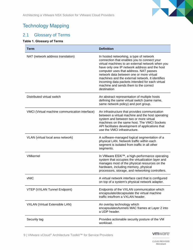
2.1 Glossary of Terms
Table 1. Glossary of Terms
Term Definition
NAT (network address translation) In hosted networking, a type of network connection that enables you to connect your virtual machines to an external network when you have only one IP network address and the host computer uses that address. NAT passes network data between one or more virtual machines and the external network. It identifies incoming data packets intended for each virtual machine and sends them to the correct destination
Distributed virtual switch An abstract representation of multiple hosts defining the same virtual switch (same name, same network policy) and port group.
VMCI (Virtual machine communication interface) An infrastructure that provides communication between a virtual machine and the host operating system and between two or more virtual machines on the same host. The VMCI Sockets API facilitates development of applications that use the VMCI infrastructure.
VLAN (virtual local area network) A software-managed logical segmentation of a physical LAN. Network traffic within each segment is isolated from traffic in all other segments.
VMkernel In VMware ESXi™, a high-performance operating system that occupies the virtualization layer and manages most of the physical resources on the hardware, including memory, physical processors, storage, and networking controllers.
vNIC A virtual network interface card that is configured on top of a system's physical network adapter.
VTEP (VXLAN Tunnel Endpoint) Endpoints of the VXLAN communication which encapsulate/decapsulate the virtual machine traffic into/from a VXLAN header.
VXLAN (Virtual Extensible LAN) An overlay technology which encapsulates/tunnels MAC frames at Layer 2 into a UDP header.
Security tag Provides actionable security posture of the VM workload.

Architecting a VMware NSX Solution for VMware Cloud Providers
10 | VMware vCloud® Architecture Toolkit™ for Service Providers
2.2 NSX for vSphere Overview
The overall goal of network and security virtualization is to at a minimum achieve the same functionality of physical network and security components and provide that functionality in a virtualized logical component. This ability is enabled by providing a centralized management platform to organize the multiple virtualized networking and security functions within a single interface. The networking and security functions supported by the VMware NSX platform are shown in the following figure.
Figure 1. VMware NSX Network and Security Functions
VMware NSX supports the following functions:
• Switching – Extension of L2 segment IP subnets anywhere in the fabric, regardless of the physical network design.
• Routing – Layer 3 logical routing between IP subnets without traffic going out to the physical router. This routing, performed in the hypervisor kernel with minimal CPU or memory overhead, provides an optimal data path for routing traffic within the virtual infrastructure (East-West communication). Similarly, VMware NSX Edge™ services gateway provides an ideal centralized point for seamless integration with the physical network infrastructure, handling communication with the external network (North-South communication).
• Distributed firewall (DFW) – Security enforcement implemented as a kernel module and providing a virtual NIC level firewall. This enables firewall rule enforcement in a highly scalable manner, without creating bottlenecks on physical appliances. The firewall is distributed in the kernel, and therefore, has minimal CPU overhead so it can perform at line-rate speed.
• Logical load balancing – Support for L4–L7 load balancing with the ability to provide SSL termination.
• VPN – SSL VPN services to enable L2 and L3 VPN services.
• IPsec VPN – Service provider configures two NSX Edge nodes and creates a site-to-site tunnel between the two edges. The networks behind the two edges are reachable with the site-to-site solution, providing the ability to interconnect two different networks.
• L2 VPN – Service provider can extend a network across boundaries such that the VMs being extended are unaware of or require any change in their routing or MAC addresses.

Architecting a VMware NSX Solution for VMware Cloud Providers
11 | VMware vCloud® Architecture Toolkit™ for Service Providers
• SSL VPN-Plus – Service provider offers this user-based solution, where an NSX Edge is provisioned with SSL VPN and the private network behind the NSX Edge is reachable through the end user’s machine after connected through the SSL VPN client.
• Connectivity to physical networks – L2 and L3 gateway functions are supported within VMware NSX for vSphere® to provide communication between workloads deployed in logical and physical spaces.
Individual VMware NSX components provide the following functionality:
• NSX Edge services gateway – Multi-functional networking and security virtualized component that provides support of both control plane and data plane functions, such as network address translation (NAT), dynamic routing protocols (OSPF, iBGP, eBGP), static routing, firewall, Identity-Based Firewall, load balancing, DHCP/DNS support, and VPN functionality with a primary focus on North-South traffic.
• Distributed logical router – Networking virtualized platform that provides support of both control plane and data plane functions of routing protocols (OSPF, BGP) with a primary focus on East-West traffic.
• Distributed firewall – Distributed firewall services integrated with the vSphere kernel for optimized performance and functionality.
• VMware NSX Controller™ cluster – Virtual appliance that provides the control plane function for the L3 routing and L2 switching components.
• VMware NSX Manager™ – Virtual appliance that centralizes the provisioning of logical networking components and manages the connection of virtual machines and storage objects to the networking functions.
• VMware NSX API™ – Restful API for interfacing with external programs, such as cloud management portals or orchestration engines.
Various VMware NSX components, as shown in the following figure, support the networking and security virtualization functions to provide an overall end-to-end network and security virtualization solution.
Figure 2. Networking and Security Virtualization Functional Components

Architecting a VMware NSX Solution for VMware Cloud Providers
12 | VMware vCloud® Architecture Toolkit™ for Service Providers
Deployment Model Considerations VMware NSX can be deployed in a number of different configurations depending on your requirements for scalability and manageability. This section highlights some of the most common deployment models for VMware NSX.
3.1 Deployment Sizing Considerations
The configuration of the VMware NSX for your cloud and hosting offering can be categorized into two main scenarios—deployment in small/medium data centers and deployment in large-scale data centers. The following considerations are valid when deploying VMware NSX in both scenarios:
• VMware vCenter Server® and NSX Manager 6.1.x have a one-to-one mapping relationship. That is, there is one NSX Manager (NSX domain) per vSphere or vCenter Server instance. (This implies the scale limit of vCenter Server governs the scale of the overall VMware NSX deployment.)
• As part of the installation process, NSX Controller instances must be deployed on the same vCenter Server that NSX Manager is connected to.
• The main difference in small/medium data center compared with large-scale data center designs is usually the number of vCenter Server instances deployed and how they map to NSX Manager.
Note VMware NSX version 6.2 can support multiple vCenter Server instances. This is out of scope for this version of the document.
3.1.1 Small/Medium Data Center Deployment
When deploying a VMware NSX solution within your cloud and hosting service offering, consider the following:
• A single vCenter server is typically deployed to manage all the VMware NSX components.
• VMware recommends deploying separate edge and management clusters to accommodate future growth.
The following figure shows a typical deployment configuration of the vCenter Server and the VMware NSX components.

Architecting a VMware NSX Solution for VMware Cloud Providers
13 | VMware vCloud® Architecture Toolkit™ for Service Providers
Figure 3. Single vSphere or vCenter Managing All NSX Components
3.1.2 Large Data Center Deployment
Large-scale cloud environments primarily use a dedicated vSphere or vCenter Server for the management cluster. vSphere or vCenter Server is typically already deployed before VMware NSX is introduced in the architecture. When that happens, one or more dedicated vCenter Server instances are added to the management cluster to manage the resources of the VMware NSX domain (edge and compute clusters) as shown in the following figure.
Figure 4. Dedicated vSphere or vCenter Server Managing All NSX Components
This design approach has the following advantages:
• Avoids circular dependencies, because the management cluster is outside of the domain it manages
• Provides mobility of management cluster for remote data center operation
• Supports integration with existing vSphere and VMware vCenter® offerings
• Provides ability to deploy more than one VMware NSX domain

Architecting a VMware NSX Solution for VMware Cloud Providers
14 | VMware vCloud® Architecture Toolkit™ for Service Providers
• Upgrade of the main vCenter Server does not affect the VMware NSX domains
• Supports use of site recovery and other explicit-state management systems
3.2 Cloud Service Offerings
This document focuses on three main service models to enable VMware Cloud Providers to deliver a unified hybrid cloud experience to their customers:
3.2.1 Hosting (Managed or Unmanaged)
VMware Cloud Provider Program Powered Hosting Services offer all the benefits of a dedicated software-defined data center and are engineered on vSphere, so they are 100 percent compatible with end customers on-premises vSphere environments. This offers a unified hybrid cloud experience with the same advantages of improved availability, recoverability, performance, and scalability to run your business-critical applications with confidence. The hosting solution can either be managed by the provider or self-managed.
3.2.1.1 VMware vSphere Client Consumption
The NSX Manager component integrates with the VMware vSphere Web Client and provides a Networking and Security plug-in that allows consumption directly from the NSX Manager for sufficiently privileged users.
This model is typically used when the consumer of the hosting services has full access to the platform and appropriate knowledge to operate the software-defined networking solution effectively.
3.2.2 Private Cloud (Managed or Unmanaged)
VMware Cloud Provider Program Powered Private Cloud Services are engineered on the VMware vRealize® Suite, and is 100 percent compatible with end customers on-premises vSphere environments. This provides a unified hybrid cloud experience with dedicated software-defined data centers, which can offer the required self-service consumption, availability, performance, and scalability to run your business-critical applications in the cloud. The private cloud solution can either be managed by the provider or self-managed.
3.2.2.1 VMware vRealize Automation Consumption
Users of VMware vRealize Automation™ can take advantage of the VMWare NSX software-defined networking and security capabilities by configuring multi-machine blueprints that create networks on-demand, or consume existing networks that are connected upstream within the data centers. Users can also isolate their deployments using firewall policies, load balancers, and NAT services within their blueprints.
Advanced users of vRealize Automation can also create additional value-add services to consume advanced features of VMware NSX through the VMware vRealize Orchestrator™ plug-in or REST API.
3.2.3 Public Cloud
VMware Cloud Provider Program Public Cloud Services are engineered on the VMware vCloud Suite® with vSphere and vCloud Director at its core. This unique combination provides complete multi-level security and a multi-tenant architecture that reduces complexity and makes policy implementation consistent with your internal data center and the VMware Cloud Provider Program, offering a unified hybrid cloud experience to the consumers.
3.2.3.1 VMware vCloud Director for Service Providers Consumption
Within VMware vCloud Director for Service Providers, the software-defined networking and security services are presented to the end users through the vCloud Director UI and API. End users have the

Architecting a VMware NSX Solution for VMware Cloud Providers
15 | VMware vCloud® Architecture Toolkit™ for Service Providers
ability to configure edge networking services, such as NAT, firewall, DHCP, VPN, and load balancer services. They also have the ability to create routed or isolated networks directly through the UI. This is all contained within the tenancy boundaries of each vCloud Director Organization.
Note Software-defined networking and security capabilities can be added to all three of the cloud service models to enhance the cloud service and functionality.
3.2.3.2 VMware vCloud Director and VMware NSX
VMware NSX is a direct replacement for the VMware vCloud® Networking and Security™ product, and provides an in-place upgrade path from vCloud Networking and Security which retains all existing configurations and provides backwards compatibility with vCloud Networking and Security APIs, and where the NSX Controller based VXLAN can be consumed immediately. NSX 6.1.x is fully supported with vCloud Director.

Architecting a VMware NSX Solution for VMware Cloud Providers
16 | VMware vCloud® Architecture Toolkit™ for Service Providers
Design Considerations
4.1 Architecture Overview
The following figure highlights an example architecture overview where a customer has deployed a VMware NSX based solution across their data center. The example uses a leaf-and-spine network topology and dedicated edge and management racks.
Figure 5. Architecture Overview

Architecting a VMware NSX Solution for VMware Cloud Providers
17 | VMware vCloud® Architecture Toolkit™ for Service Providers
4.2 Network Requirements and Topologies
VMware NSX can be implemented on top of any existing or new network topology. VMware Cloud Providers typically have a number of different network topologies, depending on what services they typically offer to their customers.
This section highlights some of the common network topologies leveraged when deploying VMware NSX and is based on the VMware NSX (NSX-V) for vSphere Network Virtualization Design Guide.
4.2.1 Classic Core/Aggregation/Access Layer Topologies
The classic core, aggregation, and access (3-tier) topology has been commonplace in most enterprises and service providers for many years and provides a scalable modular architecture for networking services.
Figure 6. 3-Tier Topology
Applications which required a Layer 2 adjacency had to be connected within the same Pod, because each Pod was separated by a Layer 3 wide-area network (WAN) connection. This was one of the primary reasons for the introduction for a leaf-spine fabric design.

Architecting a VMware NSX Solution for VMware Cloud Providers
18 | VMware vCloud® Architecture Toolkit™ for Service Providers
4.2.2 Leaf-and-Spine Fabric Design
The evolution of the leaf-and-spine design evolved based on the following requirements:
• Addressing the increasing demand of traffic for East-West communication
• Ability to deploy applications independent of the Layer 2 fabric within each Pod
Figure 7. Leaf-Spine Fabric Design
The evolved leaf-and-spine design also collapsed the number of networking layers from three logical layers (core/aggregation/access) to two logical layers (leaf-spine).
Note A border leaf is a special leaf node that supports the external connection to the WAN or Internet.
As mentioned in the VMware NSX for vSphere (NSX-V) Network Virtualization Design Guide., the following topics must be considered when defining the end-to-end network requirements:
• Simplicity
• Scalability
• High-bandwidth
• Fault-tolerance
• Quality of Service (QoS)
This document provides further detail to these areas of focus.

Architecting a VMware NSX Solution for VMware Cloud Providers
19 | VMware vCloud® Architecture Toolkit™ for Service Providers
4.3 vCenter Server Design
vCenter Server is the management and control component for the vSphere platform. Service providers can deploy any number of vCenter Server nodes to support the required scale and management.
Typically, there are two types of vCenter Server instances that VMware Cloud Providers deploy:
• Management – vCenter Server is leveraged to host all management clusters and is not under the control of VMware NSX.
• Resource/payload – vCenter Server is used to host all the resource/payload clusters for the end user workloads and is under the control the VMware NSX.
4.3.1 Design Considerations
NSX Manager instances pair with the vCenter Server instances on a 1:1 basis, so the VMware NSX solution scales in a modular fashion with the vCenter Server and can be implemented on a Pod-based approach to scalability that includes network and security services.
Avoid pairing the management vCenter Server with an NSX Manager because this could lead to a circular dependency impacting the management components with the distributed firewall.
4.4 vSphere Cluster Design
vSphere clusters are physical groups of ESXi hosts that are grouped together to create a pool of resources. Service providers can design their cluster topology to meet their needs based on factors such as costs, security, and manageability.
Typically, there are three types of clusters that service providers deploy:
• Management – Leveraged to host all management components.
• Edge services – Used to host all networking services appliances.
• Resource/payload – Where the end customer virtual workloads are located.
4.4.1 Design Considerations
For increased availability, distribute cluster hosts across racks within the data center so that a rack failure has limited impact on your cluster operation.
For large deployments, consider deploying an NSX Edge cluster for all networking services appliances for North/South traffic. This enables the provider to be deterministic as to where network traffic exits the data center and limits the need to present service VLANs to all payload hosts.
If leaf-and-spine network topology is leveraged and management hosts are distributed across racks, verify that the management L2 networking is extended across the racks so that the management network is available in both racks.

Architecting a VMware NSX Solution for VMware Cloud Providers
20 | VMware vCloud® Architecture Toolkit™ for Service Providers
4.5 NSX Manager
NSX Manager is the management component for NSX for vSphere and is typically located in the management cluster. The key functions of the NSX Manager are:
• Deployment and management of the controller cluster
• Preparation of the vSphere ESXi hosts (installation of the VIBs)
• Deployment of the edge services gateways and associated services (firewall, NAT, routing, and so on)
• Acts as the target for NSX REST API calls
4.5.1 Design Considerations
• Deploy an NSX Manager per vCenter server as of version 6.1.x. NSX Manager has a direct 1:1 mapping with the vCenter Server.
• Deploy the NSX Manager appliance to the management cluster and protect with VMware vSphere High Availability to improve availability.
• The NSX Manager appliance must be configured for appropriate configuration backup through the NSX Manager user interface options. The configuration can be backed up to a remote location on-demand or scheduled in line with existing business RPOs.
• NTP and other supporting infrastructure services, such as DNS, must be configured according to the best practices highlighted in the design guides.
The NSX Manager is a virtual appliance, which is deployed with the following specifications.
Table 2. NSX Manager Specification
Attribute Specification
Memory 12 GB
vCPU 4
Storage 60 GB

Architecting a VMware NSX Solution for VMware Cloud Providers
21 | VMware vCloud® Architecture Toolkit™ for Service Providers
4.6 NSX Controller Cluster
VMware NSX Controller instances are typically deployed to the NSX Edge cluster and are responsible for the following functions:
• Responsible for the switching and routing modules in the hypervisors
• Remove the VXLAN dependency on multicast routing/PIM in the physical network
• Provide suppression of ARP broadcast traffic in VXLAN networks
• Provide the control plane to distribute network information to ESXi hosts
• Are clustered for scale-out and high availability
4.6.1 Design Considerations
The NSX Controller cluster must be deployed in an odd number of nodes. The current limitation with version 6.1.x is three nodes. This is to maintain majority in the event of a node failure.
Distribute the NSX Controller VMs across ESXi hosts within the NSX Edge cluster. Leverage VM:VM anti-affinity rules to achieve this.
The NSX Controller VMs are deployed as virtual appliances with the following resource specifications.
Table 3. NSX Controller Cluster VM Specification
Attribute Specification
Memory 4 GB
CPU Reservation 2048 Mhz
vCPU 4
Storage 20 GB
Note Modifying settings is unsupported and memory reservation is not required.

Architecting a VMware NSX Solution for VMware Cloud Providers
22 | VMware vCloud® Architecture Toolkit™ for Service Providers
4.7 VXLAN Design Considerations
VXLAN (Virtual Extensible LAN) is an overlay technology that is used by VMware NSX to decouple the networking services from the physical network. The physical network then becomes a backbone network used to transport overlay traffic as quickly as possible. The main functions that VXLAN enables are:
• Rapid deployment of virtual networks into the data center
• Mobility of workloads across Layer 3 boundaries
• Large-scale multi-tenancy, allowing a service provider to extend their network beyond the VLAN limit of 4,096 networks within their data center
4.7.1 Design Considerations
The ESXi hosts’ VTEP network interfaces must be configured for at least 1,600 MTU through the network switches. This is to allow for the extra header bits that are applied to the packet size by VXLAN.
The concept of VXLAN replication to address scalability using Unicast Tunnel EndPoints (UTEP) and/or Multicast Tunnel EndPoints (MTEP) is documented in the design guide. However, consider the following aspects for a design implementation:
• Layer 2 deployments (L2 topology has no boundary for selecting UTEP and MTEP, because all VTEPs are on the same subnet)
o Small deployment – Unicast mode is a recommended configuration.
o Large deployment – Hybrid mode is more suited because the UTEP function cannot identify a VTEP boundary (VTEP are on same subnet) to provide efficient BUM replication per logical switch and thus scales very well.
• Layer 3 deployments
o In most cases, unicast deployment works because Layer 3 topology provides a VTEP IP addressing boundary, and therefore, UTEP efficiently replicates frame pre LS. No need for PIM because traffic is all unicast.
o For very large deployments, hybrid mode is recommended providing MTEP-based BUM replication as well eliminating configuration of L3 multicast (PIM).
• Hybrid mode deployments:
o VMware recommends configuring the external physical switch with IGMP querier along with IGMP snooping (this is an industry standard best practice for most switches, including Cisco, Arista, Dell, and Brocade).
o If you accidentally forget to configure IGMP querier in the physical switch, as long as IGMP snooping is defined, the hypervisor will send a join to the configured multicast address.
o Hybrid mode is preferred when large L2 multicast traffic from VMs requires replication.
o Be aware of multicast reserved address space and avoid using multicast addresses that will result in broadcast: http://www.cisco.com/c/dam/en/us/support/docs/ip/ip-multicast/ipmlt_wp.pdf.

Architecting a VMware NSX Solution for VMware Cloud Providers
23 | VMware vCloud® Architecture Toolkit™ for Service Providers
4.8 Transport Zone Design
The VMware NSX transport zone defines the boundaries of which ESXi hosts the VMware NSX logical switches (VXLANs) can be extended across. The ESXi hosts participating within a transport zone need to communicate with each other over a VXLAN Tunnel Endpoint (VTEP) connection. VMware Cloud Providers can configure transport zones in different ways depending on their cloud service model. For example, a public cloud service might leverage a single transport zone across their data center for simplicity, whereas a hosting or private cloud model might leverage a transport zone per tenant to avoid replicating all networks across all hosts within the data center.
4.8.1 Design Considerations
• Span the transport zone across all the ESXi hosts or clusters that the end customers’ VMs must reside on so that all specified hosts can service the required network traffic.
• Verify that the transport zone is extended to the NSX Edge clusters so that East/West traffic can get to the NSX Edge cluster before traversing the North/South edge service gateways.
• Isolated transport zones can be used to improve security where required. These transport zones are only applied to the required clusters.
• VMware NSX provides flexibility for the VXLAN transport which does not require complex multicast configurations on the physical network to be in place. This flexibility is provided through different VXLAN replication modes you can choose depending on your network fabric. They are:
o Unicast – All replication occurs using unicast. This is applicable to small deployments.
o Multicast– The entire replication is offloaded to the physical network and requires IGMP querier as well as multicast routing for L3 (PIM). It is the host that provides the necessary querier function. However, an external querier is recommended for manageability.
o Hybrid – Local replication is offloaded to the physical network, while remote replication occurs through unicast. This is the most practical replication mode without the complexity of multicast mode and only requires IGMP snooping/querier and does not require L3 PIM.
o All VXLAN replication modes require an MTU of 1,600 bytes.

Architecting a VMware NSX Solution for VMware Cloud Providers
24 | VMware vCloud® Architecture Toolkit™ for Service Providers
4.9 VMware NSX Distributed Firewall
The VMware NSX distributed firewall provides L2-L4 stateful firewall services to any workload in the VMware NSX environment. The distributed firewall is embedded in the ESXi kernel, scales horizontally with the ESXi hosts, and performs at line rate. It is designed to provide protection, isolation, and segmentation of East/West traffic within the data center environment.
VMware Cloud Providers can leverage this functionality to offer zero-trust micro-segmentation to their customers’ hosted workloads, and controlled isolated access to shared management resources where required.
4.9.1 Design Considerations
• Distributed firewall enforcement is applied at the vNIC level of the VMs.
• If the management components are under control of VMware NSX, the components must be excluded from participation within the distributed firewall to avoid circular dependencies. For example, you could edit a rule that blocks access to the vCenter Server.
• Collapsing application tiers to common services with each application tier having its own logical switch:
o Better for managing domain (web and database) specific security requirements.
o Easier to develop segmented isolation between application tiers (web-to-database compared with web-to-application granularity).
o Requires explicit security between application tiers.
• Collapsing all application tiers into single logical switch:
o Better for managing group/application-owner specific expertise.
o Applications container model. Suits the application as tenant model.
o Simpler security group construct per application tier.
o Security policy between different applications container is required.
• DMZ model
o Zero-trust security.
o Multiple DMZ logical networks. Default deny_ALL within DMZ segments.
o External to internal protection by multiple groups.
A DFW policy can be applied to various objects in the Virtual Inventory such as: Security Tags, IP Sets, MAC Sets, VMs, Port Groups and Logical Switches, Folders, Clusters, as well as user group identity information from Active Directory.

Architecting a VMware NSX Solution for VMware Cloud Providers
25 | VMware vCloud® Architecture Toolkit™ for Service Providers
4.10 Service Composer
Service Composer provides policy object and policy enforcement points (PEPs) to help you provision and assign network and security services to applications in a virtual infrastructure. You map these services to a security group, and the services are applied to the virtual machines in the security group.
4.10.1 Security Groups
Security groups are logical groupings created to define what needs to be protected by the VMware NSX distributed firewall or similar devices. A typical strategy is to add vCenter Server inventory objects as security group members. The underlying firewall rules configured within the kernel are IP-based, despite being abstracted as objects at the configuration layer. This requires VMware Tools™ to be run in all virtual machines so that their addresses are reported in the vCenter Server.
Membership of a security group can be achieved in a number of ways ranging from vCenter Server objects, security tags, IPsets, MACsets or other security groups, directory groups, or regular expressions.
4.10.2 Security Policy
A VMware NSX security policy is a collection of networking and security services. The services that can be added include:
• Endpoint services – Data security, anti-virus, vulnerability management
• Distributed firewall rules
• Network introspection services
4.10.3 Design Considerations
Where security groups are leveraged, VMware Tools must be installed on the virtual machines to obtain full management functionality. VMware NSX distributed firewall requires up-to-date IP information from the VM to be reported in vCenter.
When you have many security groups to which you need to attach the same security policy, create an umbrella security group that includes all these child security groups, and apply the common security policy to the umbrella security group so that the VMware NSX distributed firewall uses ESXi host memory efficiently.

Architecting a VMware NSX Solution for VMware Cloud Providers
26 | VMware vCloud® Architecture Toolkit™ for Service Providers
4.11 NSX Edge Services Gateways
• NSX Edge services gateway is a multi-functional virtualized networking and security component that provides support of both control plane and data plane functions, such as network address translation (NAT), routing protocols (OSPF, iBGP, eBGP), firewall, load balancing, DHCP/DNS support, and VPN functionality with a primary focus on the North-South traffic.
• The NSX Edge services gateway must be deployed as an HA pair to address high availability requirements. This creates a VM:VM anti-affinity rule to support the HA function.
• For improved throughput for the routing capabilities, the provider can implement equal-cost multi-path (ECMP) high-availability. With this model we can deploy up to eight ECMP edge devices to improve throughput and availability.
• The NSX Edge services gateway must be deployed in the correct size profile as driven by network functional and performance requirements.
• NSX Edge services gateway appliance deployments are typically configured with the following resources:
o X-Large = 6 x vCPU, 8,192 MB vRAM (high-performance firewall + load balancer + routing)
o Quad-Large = 4 x vCPU, 1,024 MB vRAM (high-performance firewall)
o Large = 2 x vCPU, 1.024 MB vRAM
o Compact = 1 x vCPU, 512 MB
The following table lists other configuration property limits for different size deployments.
Table 4. NSX Edge Services Properties Limits Based on Deployment Size
Network Function Value (Compact / Large / X-Large / Quad-Large)
NSX Edge services gateways 2,000
Note HA does not change the scaling requirements for NSX Edge
Interfaces 10 (internal, uplink, or trunk)
Note With trunk, 200 sub-interfaces per NSX Edge
Router
NAT rules per NSX Edge services gateway 2,000 (all sizes)
Static routes per NSX Edge services gateway
2,048 (all sizes)
BGP routes per NSX Edge services gateway
20K / 50K / 250K / 250K
BGP neighbours per NSX Edge services gateway
10 / 20 / 50 / 50
BGP routes redistributed No limit

Architecting a VMware NSX Solution for VMware Cloud Providers
27 | VMware vCloud® Architecture Toolkit™ for Service Providers
Network Function Value (Compact / Large / X-Large / Quad-Large)
OSPF routes per NSX Edge services gateway
20K / 50K / 100K / 100K
OSPF adjacencies per NSX Edge services gateway
10 / 20 / 40 / 40
OSPF routes redistributed 2K / 5K / 20K / 20K
Total number of routes 20K / 50K / 250K / 250K
Firewall
Firewall rules per NSX Edge services gateway
2,000
Concurrent connections per host (compact/all other)
64 K / 1 M
Load balancing
Load balancer VIPs per ESXi 64
Load balancer pools per ESXi 64
Load balancer servers per pool 32
DHCP
DHCP pools per NSX Edge services gateway
20K
IPsec / VPN
IPsec sites per NSX Edge services gateway (only for pre-6.1, no limit for 6.1 or later)
64
IPsec tunnels per NSX Edge services gateway
512 / 1,600 / 4,096 / 6,000

Architecting a VMware NSX Solution for VMware Cloud Providers
28 | VMware vCloud® Architecture Toolkit™ for Service Providers
4.12 VMware NSX Distributed Logical Router
• The VMware NSX distributed logical router provides support of both control plane and data plane functions of routing protocols (OSPF, BGP) with a primary focus on the East-West traffic.
• VMware Cloud Providers can leverage distributed logical routing functionality to address the scale requirements for routed interfaces and optimize the East/West networking traffic within the data center. The provider can also run dynamic routing protocols between the distributed logical router and the NSX Edge router of external physical routing devices.
4.12.1 Design Considerations
• The VMware NSX distributed logical router can scale up to 1,000 logical interfaces, which gives the provider the ability to allow the end users within the cloud environment the ability to deploy up to 1,000 networks within this distributed logical router.
• For increased availability the distributed logical router control VM must be deployed in an HA pair. HA is provided in an active/standby configuration.
• The distributed logical router is heavily dependent on the NSX Controller cluster. Verify that the controller cluster is up and running before making any changes to the distributed logical router.
4.13 NSX Logical Switches
A logical switch is mapped to a unique VXLAN, which encapsulates the virtual machine traffic and carries it over the physical IP network. Logical switches are isolated by nature within the cloud platform. Each logical switch is its own L2 broadcast domain. A cloud consumer or provider can create logical switches that span their area of the infrastructure within the transport zone. As the logical switch is expanded across the transport zone, and inherently, the distributed virtual switch and clusters, this enables the virtual machine to be moved across the data center with VMware vMotion®.
The NSX Controller cluster controls logical switches and maintains information about virtual machines, ESXi hosts, logical switches, and VXLANs.
The control plane mode decouples NSX for vSphere from the physical network and handles the broadcast, unknown unicast, and multicast (BUM) traffic within the logical switches. All logical switches created within the transport zone inherit VMware NSX transport zone settings. (This behavior can be overwritten by the customer.) Other options to consider when designing the logical switch control plane are described in following sections.
4.13.1 Multicast Mode
In multicast mode, the control plane uses multicast IP addresses on the physical network. VMware recommends this configuration when upgrading from existing VXLAN deployments. This design requires the configuration of PIM/IGMP on the physical network.
4.13.1.1 Design Considerations
• Requires IGMP and IGMP snooping configurations throughout the physical network which adds complexity to the configuration and is not always available on the network.
• Multicast IP addresses must be reserved on the physical network.
• The use of multicast mode reduces the overhead incurred on the source host VTEPs.

Architecting a VMware NSX Solution for VMware Cloud Providers
29 | VMware vCloud® Architecture Toolkit™ for Service Providers
4.13.2 Unicast Mode
In unicast mode, the NSX Controller nodes handle the control plane. All replication is configured locally on the host. No multicast IP addresses or physical network configurations are required for this mode to operate.
4.13.2.1 Design Considerations
• No requirement for multicast configurations on the physical networks.
• The use of unicast mode increases the overhead on the source hosts VTEPs.
4.13.3 Hybrid Mode
Hybrid mode is an optimized version of unicast mode where local traffic replication for the subnet is offloaded to the physical network. Operation in this mode requires IGMP snooping on the first-hop switch and IGMP querier must be available, but the requirement for PIM is removed.
4.13.3.1 Design Considerations
• IGMP snooping configuration is required on the physical network.
• Multicast IP addresses must be reserved on the physical network.
Architecting a VMware NSX Solution for VMware Cloud Providers
30 | VMware vCloud® Architecture Toolkit™ for Service Providers
Key Use Cases This section highlights some of the key VMware Cloud Provider use cases for VMware NSX. Employment of the use cases might vary depending on the consumption model and service model that the provider offers. The provider might also choose to offer some of the use cases as managed services that their operations teams can execute on behalf of the end customers.
5.1 Customer On-Premises-to-Hosted Cloud Connectivity
One key VMware Cloud Provider use case is to provide services that enable the end customers to connect their on-premises vSphere implementations to the hosted cloud service.
With VMware NSX, there are several options available to create a common network between the customer and provider.
• IPsec VPN – The consumer can configure an IPsec VPN service from their hosted cloud NSX Edge gateway device that is configured to pair with a third-party VPN endpoint or standalone NSX Edge in the customer’s data center. The VPN connectivity is achieved over L3 connectivity.
• L2VPN – The consumer can create a L2 VPN service from their hosted cloud NSX Edge services gateway device that is configured to pair with a standalone NSX Edge device in the customer’s data center. The L2 VPN stretches the same Layer 2 network between sites.
VMware NSX supports L2VPN connectivity for both VLAN-backed and VXLAN-backed networks as described in the VMware NSX for vSphere Administration Guide – NSX 6.1 for vSphere, and this capability can be leveraged between private and public cloud environments (NSX version 6.1) as shown in the following figures.

Architecting a VMware NSX Solution for VMware Cloud Providers
31 | VMware vCloud® Architecture Toolkit™ for Service Providers
Figure 8. VMware NSX L2VPN Using a VLAN/VXLAN-Based Solution
As depicted in the figure, a VMware NSX Edge services gateway must be deployed in the private and public cloud environments. In the case of a VLAN-backed network in the private cloud, a standalone NSX Edge gateway must be used for the end-to-end deployment (edge services gateway is deployed without the entire site being VMware NSX enabled). This allows for the seamless migration of VLAN-based or VXLAN-based workloads between locations.

Architecting a VMware NSX Solution for VMware Cloud Providers
32 | VMware vCloud® Architecture Toolkit™ for Service Providers
Figure 9. VMware NSX L2VPN Using VXLAN-to-VXLAN-Based Solution
Note The data center connectivity options can either be self-serviced by the end users or provider managed, depending on the service model offered.

Architecting a VMware NSX Solution for VMware Cloud Providers
33 | VMware vCloud® Architecture Toolkit™ for Service Providers
5.2 Securing Applications and Networks in the VMware Cloud Provider Program
VMware Cloud Providers can enable their customers to configure security rules on the NSX Edge service gateways. This allows the end user to create associated application firewall rules and NAT rules so that their applications are appropriately secured within the cloud environment.
This use case is particularly useful for service providers who offer direct Internet connectivity and public IP addressing from within the customer’s NSX Edge services gateway.
Figure 10. Securing Applications with NSX Edge Firewall and NAT

Architecting a VMware NSX Solution for VMware Cloud Providers
34 | VMware vCloud® Architecture Toolkit™ for Service Providers
5.2.1 Consumption Models
• vCloud Director for Service Providers – Public cloud services built with vCloud Director for Service Providers can offer self-service consumption of NSX Edge services, which include NSX Edge firewall and NAT. The provider can also offer this as a managed service.
• vRealize Automation – Private cloud services built with vRealize Automation can consume NSX Edge services through definition of appropriate service blueprints. The service provider can also create offerings for API-driven configuration of the NSX Edge gateway services if required.
• vSphere Web Client – Hosting services providers can give their end customers full access to VMware NSX functionality, which includes the configuration of the edge gateway, firewall, and NAT services. The provider could also offer this as a managed service.
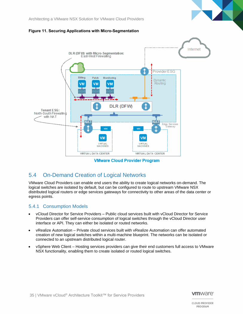
5.3 Micro-Segmentation
Micro-segmentation with VMware NSX can enable VMware Cloud Providers to implement zero-trust security and protection of sensitive virtual machine workloads in the cloud environment. By using VMware NSX distributed firewalls, VMware NSX micro-segmentation can provide cloud workloads that reside on the same Layer 2 segment a similar level of isolation and segmentation to workloads on separate Layer 2 segments. This allows for more granular and efficient security for cloud workloads.
VMware Cloud Providers can provide micro-segmentation in the vSphere Web Client for the Hosted Cloud Service model or through the consumption of multi-machine blueprints for the Private Hosted Cloud Service model. An example of using micro-segmentation with the distributed firewall platform might be in the case where the service provider wants to protect the back end infrastructure, which offers billing, patch, and monitoring services. This would allow for the protection of East/West traffic while the edge services gateway firewall provides the North/South protection.
Architecting a VMware NSX Solution for VMware Cloud Providers
35 | VMware vCloud® Architecture Toolkit™ for Service Providers
Figure 11. Securing Applications with Micro-Segmentation
5.4 On-Demand Creation of Logical Networks
VMware Cloud Providers can enable end users the ability to create logical networks on-demand. The logical switches are isolated by default, but can be configured to route to upstream VMware NSX distributed logical routers or edge services gateways for connectivity to other areas of the data center or egress points.
5.4.1 Consumption Models
• vCloud Director for Service Providers – Public cloud services built with vCloud Director for Service Providers can offer self-service consumption of logical switches through the vCloud Director user interface or API. They can either be isolated or routed networks.
• vRealize Automation – Private cloud services built with vRealize Automation can offer automated creation of new logical switches within a multi-machine blueprint. The networks can be isolated or connected to an upstream distributed logical router.
• vSphere Web Client – Hosting services providers can give their end customers full access to VMware NSX functionality, enabling them to create isolated or routed logical switches.

Architecting a VMware NSX Solution for VMware Cloud Providers
36 | VMware vCloud® Architecture Toolkit™ for Service Providers
5.5 VMware NSX Dynamic Routing Scenario (Provider/Tenant) with MPLS
As provider and tenant functional requirements begin to expand in the public cloud, there might be a need to enable VMware NSX dynamic routing protocols, such as OSPF, to multiple network and security elements for both provider and tenant environments. When connecting to a third-party MPLS backbone, you can use BGP (external BGP/eBGP) as a dynamic routing protocol to exchange network information with the local backbone provider. The following figure provides an example of a Dedicated Private Cloud scenario where the service provider offers an environment for a single tenant.
Figure 12. VMware NSX Dynamic Routing Scenario with eBGP (External BGP) and OSPF
The following are the design considerations of this use case:
• OSPF can be configured between the tenant distributed logical router (to redistribute connected routes) and the management NSX Edge services gateway (to redistribute connected and static routes). Provider Edge NSX Edge services gateway A defines a shared OSPF Area 0. This supports end-to-end connectivity from the tenant logical networks to the provider management networks.

Architecting a VMware NSX Solution for VMware Cloud Providers
37 | VMware vCloud® Architecture Toolkit™ for Service Providers
• Dynamic routing is disabled between the provider management NSX Edge services gateway and the physical management router. Static routes for the management networks are created on the provider management NSX Edge services gateway.
• BGP filters are created on the tenant provider NSX Edge services gateway to deny collection of routes from the WAN edge router. There is a large amount of network information from the WAN backbone provider that does not need to be collected in the local provider environment.
• Overlapping IP addresses are unsupported for the Internal Tenant Networks (logical switches).
5.6 Independent Networking and Security Functions
Certain networking and security virtualization features can currently be deployed independent of the VMware NSX functionality by using the Edge Gateway component, which is controlled and deployed by vCloud Director in legacy compatibility mode. As shown in the following figure, the Edge Gateway can support the interconnectivity of the virtual machines that are connected through the VXLAN-backed infrastructure. This infrastructure is the Org VDC Network – VXLAN500x connected to the physical northbound L3/L2 network through a VLAN-backed infrastructure (vCloud Director External Network VLAN 101).
Figure 13. Edge Gateway Deployment by vCloud Director for Service Providers (VLAN-to-VXLAN)

Architecting a VMware NSX Solution for VMware Cloud Providers
38 | VMware vCloud® Architecture Toolkit™ for Service Providers
5.7 NSX Provider Edge Independent of vCloud Director
VMware NSX components can be introduced into service provider cloud offerings independent of the cloud management platform to include provider-facing functionality as highlighted in the following figure.
Figure 14. Provider Edge Configuration Independent of vCloud Director Platform
An NSX Edge services gateway called the Provider Edge is introduced to leverage all of the VMware NSX functionality, such as L2VPN and L2 bridging. The Provider Edge provides the VLAN-to-VXLAN routing function (VLAN101 to vCloud Director external network VXLAN5001), as the Edge Gateway did in the previous use case. This allows for an additional level of separation of the networking and security functions between the provider (transit transport zone) and the tenant (provider VDC transport zone) environments.

Architecting a VMware NSX Solution for VMware Cloud Providers
39 | VMware vCloud® Architecture Toolkit™ for Service Providers
Availability
6.1 NSX Manager
Because the NSX Manager is a virtual machine, the recommendation is to approach the topic of resiliency and overall high availability in the same way as other vSphere components, by utilizing the vSphere HA functionality. That way, NSX Manager can be moved dynamically to other parts of the infrastructure in case of a failure. In such a situation, the NSX management plane is impacted, while the already deployed logical networks (data plane) continue to operate.
6.2 NSX Controller Cluster
When NSX Controller clusters are deployed, a “master” controller node is chosen through an election process where its role is to allocate resources to individual controller nodes and determine when a node has failed.
The election process of a master requires a majority vote of all active and inactive controller nodes and is the primary reason for the odd number of nodes within a deployed controller cluster as described in the NSX for vSphere design guide.
Figure 15. Number of Nodes Required to Maintain HA in a VMware NSX Cluster
Note The VMware NSX 6.1.x solution supports three-node clusters. The additional options are provided to illustrate the majority vote mechanism process.

Architecting a VMware NSX Solution for VMware Cloud Providers
40 | VMware vCloud® Architecture Toolkit™ for Service Providers
6.3 NSX Edge Services Gateway
The NSX Edge services gateway high availability (HA) feature provides that an NSX Edge services gateway appliance is always available by installing an active pair of NSX Edge services gateways in the virtualized infrastructure. There is the option to enable high availability either when installing the NSX Edge services gateway device or on an already deployed NSX Edge services gateway instance.
The primary NSX Edge services gateway appliance is in the active state and the secondary appliance is in the standby state. The NSX Edge services gateway replicates the configuration of the primary appliance for the standby appliance. VMware recommends that the primary and secondary appliance be created on separate resource pools and datastores. If you create the primary and secondary appliances on the same datastore, the datastore must be shared across all hosts in the cluster. In this way, the high availability appliance pair can be deployed on different ESXi hosts. If the datastore is a local storage, both virtual machines are deployed on the same host.
In the operation of the primary appliance, it maintains a heartbeat with the standby appliance and sends service updates through an internal interface. If a heartbeat is not received from the primary appliance in the specified time, which is configurable, the primary appliance is declared dead. The standby appliance moves to the active state and takes over the interface configuration of the primary appliance. The standby appliance also starts the NSX Edge gateway services that were running on the primary appliance.
6.3.1 Stateful Active/Standby HA Deployment for NSX Edge Services Gateway
This design follows the redundancy model where a pair of NSX Edge services gateways is deployed for each tenant. One NSX Edge gateway functions in active mode (that is, actively forwards traffic and provides the other logical network services), whereas the other unit is in standby state, waiting to take over should the active NSX Edge gateway fail.

Architecting a VMware NSX Solution for VMware Cloud Providers
41 | VMware vCloud® Architecture Toolkit™ for Service Providers
Figure 16. Stateful Active/Standby HA Deployment for NSX Edge Services Gateway

Architecting a VMware NSX Solution for VMware Cloud Providers
42 | VMware vCloud® Architecture Toolkit™ for Service Providers
6.3.2 Standalone Deployment for NSX Edge Services Gateway
A standalone HA model for NSX Edge services gateway HA inserts two independent NSX Edge appliances between the distributed logical router and the physical network as shown in the following figure. This configuration is supported when running NSX 6.x.
Note Starting with NSX 6.1, you can also choose to implement the ECMP model for high availability as described in the next section.
Figure 17. Standalone Deployment for NSX Edge Services Gateway

Architecting a VMware NSX Solution for VMware Cloud Providers
43 | VMware vCloud® Architecture Toolkit™ for Service Providers
6.3.3 Equal-Cost Multi-Path High Availability for NSX Edge Services Gateway
In the ECMP model, distributed logical routing and NSX Edge capabilities have been improved to support up to eight equal-cost paths in their forwarding table. This means that up to eight active NSX Edge instances can be deployed at the same time and all the available control and data planes are fully utilized, as shown in the following figure.
This HA model provides two main advantages:
• An increase in available bandwidth for North/South communication (up to 80 Gbps per tenant).
• Reduced traffic outages (in terms of percentage of affected flows) for NSX Edge failure scenarios.
Note As of the NSX for vSphere 6.1.2 release, there is an option to disable the edge services gateway firewall function when enabling the ECMP feature if required.
Figure 18. ECMP High Availability Deployment for NSX Edge Services Gateway

Architecting a VMware NSX Solution for VMware Cloud Providers
44 | VMware vCloud® Architecture Toolkit™ for Service Providers
6.4 NSX Distributed Logical Router Control VMs
Deploying a distributed logical router also deploys a controller VM that lives within the edge cluster. You can specify that the control VMs use high availability, which deploys an active/standby specification to improve availability.
The primary function of the distributed logical routing feature in the VMware NSX platform is to provide an optimized and scalable way of handling East/West traffic in a data center.
When routing between virtual networks, these Layer 3 networks are distributed in the ESXi hypervisor. Here the distributed logical router optimizes the routing and data path, and supports both single-tenant or multi-tenant deployments. For example, a network contains two VNIs that have the same IP addressing. With this scenario, two different distributed logical routers must be deployed with one distributed logical router connecting to tenant A and one to tenant B.
It is the job of the NSX Manager to configure and manage the routing service. During the configuration process, the NSX Manager deploys the logical router control virtual machine and then pushes the logical interface (LIF) configurations to each host through the control cluster. The logical router control virtual machine is the control plane component of the routing process and the logical router control virtual machine supports both the OSPF and BGP protocols.

Architecting a VMware NSX Solution for VMware Cloud Providers
45 | VMware vCloud® Architecture Toolkit™ for Service Providers
Manageability
7.1 Cloud Consumption Models
NSX for vSphere is designed to be consumed through a self-service portal or REST API, depending on the service model that the cloud provider wants to achieve, and dictates how the provider and the end users consume VMware NSX resources.
7.1.1 Hosting Solution
Through the vSphere Web Client, hosting services providers can give their end customers full access to the VMware NSX functionality to create and manage networking resources.
7.1.2 Private Cloud Solution
Private cloud services built with vRealize Automation offer automated creation of VMware NSX networking and security services within a multi-machine blueprint or through the API (using vRealize Orchestrator).
7.1.3 Public Cloud Solution
Public cloud services built with vCloud Director for Service Providers offers self-service consumption of NSX Edge networking and security services through the vCloud Director user interface or API.
7.2 NSX for vSphere Logging Considerations
All VMware NSX components, such as NSX Controller, VMware NSX Virtual Switch™, and NSX Edge, provide detailed network visibility and data. The VMware NSX platform offers centralized reporting and monitoring, distributed performance and scale, and is designed for automation. VMware NSX is built on a REST API provided by NSX Manager, and all operations can be performed programmatically through scripting or higher-level languages.

Architecting a VMware NSX Solution for VMware Cloud Providers
46 | VMware vCloud® Architecture Toolkit™ for Service Providers
Figure 19. NSX for vSphere Logging Environment
ESXi hosts run a syslog service (vmsyslogd) that provides a standard mechanism for logging messages
from VMkernel and other system components. ESXi can also be configured to send the logs across the network to a VMware vRealize Log Insight™ server. There are multiple levels of logging to consider.
Note Configuration of the vRealize Log Insight service on ESXi can be performed using host profiles, the vSphere command-line interface, or the advanced configuration options in the VMware vSphere Client™.
The following log files are related to NSX and must be sent to an appropriate log collection service such as vRealize Log Insight:
• Distributed firewall packet logs can be found at /var/log/dfwpktlogs.log.
• Distributed firewall userworld agent logs are located at /var/log/vsfwd.log.
• Netcpa (userworld agent) logs can be found at /var/log/netcpa.log. This log file contains
messages regarding controller-to-host communication details.
• Logical switch (VXLAN), distributed logical router and VMware Internetworking Service Insertion Platform (VSIP) kernel module logs are available at /var/log/vmkernel.log. The logical switch
related logs will be tagged with vxlan, the distributed logical router related logs will be tagged with vdrb, and the VSIP-related logs will be tagged with vsip.
• DVS logs are also available at /var/log/vmkernel.log

Architecting a VMware NSX Solution for VMware Cloud Providers
47 | VMware vCloud® Architecture Toolkit™ for Service Providers
7.3 Management Interfaces
The following section describes management interfaces for NSX for vSphere components that must be specifically enabled.
7.3.1 Distributed Logical Router Control Virtual Machine
When a distributed logical router is deployed, the logical router control virtual machine is also and it handles all control plane communications for the distributed logical router.
The distributed logical router provides a management interface configuration through the user interface, which supports management services, such as SSH, for remote connectivity. The logical router control VM communicates with the NSX Controller through a VMCI interface.
Note The logical router control VM does not have an actual IP address assigned although the management interface is connected to the same management virtual distributed switch port group as the NSX Controller.
7.3.2 VMware NSX Distributed Firewall Monitoring
The VMware NSX distributed firewall must have enough memory to avoid dropping traffic. The firewall administrator is notified of the lack of available memory by the following methods:
• An alert sent when a new rule cannot be configured due to the shortage.
• A syslog message that states the distributed firewall cannot create new connections due to the shortage. If the rule relating to the flow creation has logging turned on, a second message is generated to indicate that the packet was also dropped.
Freeing memory on a host, by moving a guest to another host, for example, resolves the issue.
If the distributed firewall virtual CPUs reach a maximum limit, packets might also be dropped. If logging is enabled for that flow, a log message is also generated for the dropped packets.
In an All Failure scenario, packets are discarded and the distributed firewall operates in a fail-closed mode until the failure is remedied.

Architecting a VMware NSX Solution for VMware Cloud Providers
48 | VMware vCloud® Architecture Toolkit™ for Service Providers
Performance and Scalability
8.1 Performance of Networking and Security in a Virtualized Environment
8.1.1 Quality of Service (QoS Layer 3) and Differentiated Services (DSCP Layer 2)
NSX for vSphere allows trust of the Differentiated Service Code Point (DSCP) marking originally applied by a virtual machine, or explicitly modifying and setting the DSCP value at the logical switch level. In both cases, the DSCP value is propagated to the outer IP header of VXLAN encapsulated frames. This enables the external physical network to prioritize the traffic based on the DSCP setting on the external header. Both quality of service (QoS) and DSCP are good examples of how physical and virtual networking can work together under a common set of rules. Using both QoS and DSCP which are networking standards, allows network switches to prioritize certain network traffic over others, which in turn helps your critical workloads get the network priority required to meet business demands.
You can verify that the application traffic flowing through the physical network infrastructure is prioritized by using the following:
• Class of Service (CoS): Layer 2 tag
• Differentiated Services Code Point (DSCP) marking: Layer 3 tag
Traffic can be classified in different ways. In a Layer 2 frame, the 802.1q header contains the information for the class of service (CoS). The first 16 bits are always 0x8100, which means that the header contains a VLAN tag. The class of service is in the next 3 bits followed by a flag that indicates whether to fragment.
Layer 3 has a different field called DSCP that has 6 bits. The first three values typically match the first three CoS bits. At the boundary between Layers 2 and 3, the switch can take the CoS and other factors like the source or destination address and match that to a Layer 3 DSCP value. Because DSCP has more potential values, it can be more specific about the service that it is going to provide.
Figure 20. QoS Layer 3 and DSCP Layer 2

Architecting a VMware NSX Solution for VMware Cloud Providers
49 | VMware vCloud® Architecture Toolkit™ for Service Providers
8.2 Scalability of Virtualized Cloud Environments
The service provider topology described in earlier sections can be scaled out as shown in the following figure. The figure shows nine tenants served by the NSX Edge services gateway on the left and the remaining nine by the NSX Edge services gateway on the right. Service providers can easily provision additional NSX Edge services gateways to serve additional tenants.
Figure 21. Scalability Deployment Example with NSX Edge Services Gateway
8.2.1 Scalability of NSX for vSphere Components
There is a one-to-one mapping between NSX Manager and vCenter Server in version 6.1.x. Should the inventory of a portion of the hybrid cloud exceed the limits supported by a single vCenter Server, a new NSX Manager must be deployed along with any new vCenter Server added. Transport zones can be extended and scaled larger by adding more vSphere compute and NSX Edge clusters until vCenter Server limits are reached. There is a limit of 1,000 distributed logical routers per ESXi host when using NSX for vSphere 6.1.2 and above. As a design consideration, if you want to exceed the 1,000 distributed logical router limit in a VMware NSX domain, you must create multiple transport zones with different clusters in each transport zone. There are many factors that determine the scalability limits in NSX for vSphere 6.1.x and 6.2, as well as other vCenter Server limits which will likely be exceeded before reaching the limit on the NSX for vSphere components.
Note For scaling the throughput of the Northbound connection to the Internet, refer to Section 6.3.3, Equal-Cost Multi-Path High Availability for NSX Edge Services Gateway.
NSX ESG X-Large(Route Aggregation Layer)
Transit VXLAN 5100
Tenant NSX ESGTenant NSX ESG
Tenant DLR Tenant DLR
External Networks
VXLAN VXLAN VXLAN VXLAN VXLAN VXLAN

Architecting a VMware NSX Solution for VMware Cloud Providers
50 | VMware vCloud® Architecture Toolkit™ for Service Providers
Recoverability The topic of recoverability for network and security virtualization within in a VMware Cloud Provider Program environment relates to the ability to back up and restore the following associated VMware NSX components:
• NSX Manager
• NSX Edge
• NSX firewall rules
• NSX Service Composer
• Virtual distributed switch
• vCenter Server
At a minimum, service providers must make regular backups of NSX Manager and vCenter Server to
restore the system state in the event of a catastrophic failure.
The overall backup frequency and schedule might vary based on business need and operational procedures set up by operational teams. However, VMware recommends having the same number of NSX backups as there are configuration changes. NSX Manager backups can be made on demand or on an automated hourly, daily, or weekly basis. To restore the system state after a failure, the recommended
timeframe to make backups is the following:
• Before an NSX or vCenter Server upgrade.
• After an NSX or vCenter Server upgrade.
• During or after Day Zero deployment and configuration of VMware NSX components (creation of controllers, logical switches, distributed logical router, NSX Edge components, security, and firewall
policies).
• Following infrastructure changes.
• After any major Day2 changes.
Synchronize VMware NSX component backups (NSX Manager and NSX Controller) with your backup schedule for other dependent components (vCenter Server, cloud management systems, operational tools, and so on). This will capture the entire system state at a given time, and give you a stable state in
time to which you can roll back.
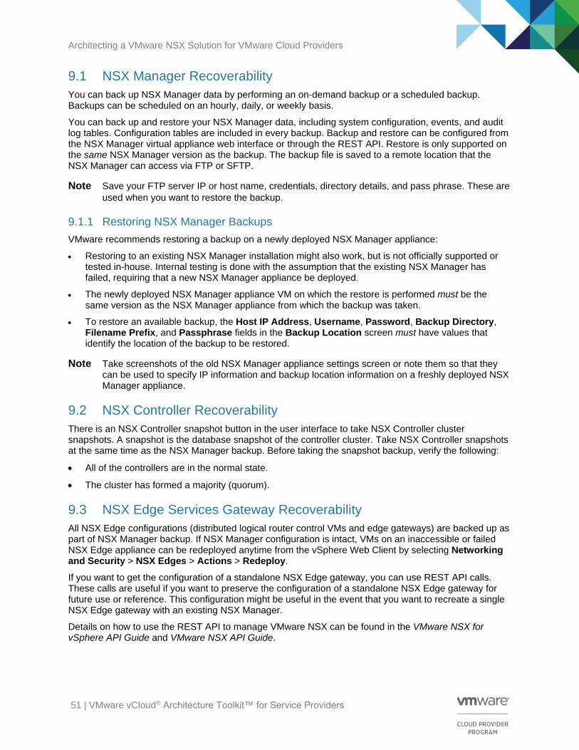
Architecting a VMware NSX Solution for VMware Cloud Providers
51 | VMware vCloud® Architecture Toolkit™ for Service Providers
9.1 NSX Manager Recoverability
You can back up NSX Manager data by performing an on-demand backup or a scheduled backup. Backups can be scheduled on an hourly, daily, or weekly basis.
You can back up and restore your NSX Manager data, including system configuration, events, and audit log tables. Configuration tables are included in every backup. Backup and restore can be configured from the NSX Manager virtual appliance web interface or through the REST API. Restore is only supported on the same NSX Manager version as the backup. The backup file is saved to a remote location that the NSX Manager can access via FTP or SFTP.
Note Save your FTP server IP or host name, credentials, directory details, and pass phrase. These are
used when you want to restore the backup.
9.1.1 Restoring NSX Manager Backups
VMware recommends restoring a backup on a newly deployed NSX Manager appliance:
• Restoring to an existing NSX Manager installation might also work, but is not officially supported or tested in-house. Internal testing is done with the assumption that the existing NSX Manager has failed, requiring that a new NSX Manager appliance be deployed.
• The newly deployed NSX Manager appliance VM on which the restore is performed must be the same version as the NSX Manager appliance from which the backup was taken.
• To restore an available backup, the Host IP Address, Username, Password, Backup Directory, Filename Prefix, and Passphrase fields in the Backup Location screen must have values that identify the location of the backup to be restored.
Note Take screenshots of the old NSX Manager appliance settings screen or note them so that they can be used to specify IP information and backup location information on a freshly deployed NSX Manager appliance.
9.2 NSX Controller Recoverability
There is an NSX Controller snapshot button in the user interface to take NSX Controller cluster snapshots. A snapshot is the database snapshot of the controller cluster. Take NSX Controller snapshots at the same time as the NSX Manager backup. Before taking the snapshot backup, verify the following:
• All of the controllers are in the normal state.
• The cluster has formed a majority (quorum).
9.3 NSX Edge Services Gateway Recoverability
All NSX Edge configurations (distributed logical router control VMs and edge gateways) are backed up as part of NSX Manager backup. If NSX Manager configuration is intact, VMs on an inaccessible or failed NSX Edge appliance can be redeployed anytime from the vSphere Web Client by selecting Networking and Security > NSX Edges > Actions > Redeploy.
If you want to get the configuration of a standalone NSX Edge gateway, you can use REST API calls. These calls are useful if you want to preserve the configuration of a standalone NSX Edge gateway for future use or reference. This configuration might be useful in the event that you want to recreate a single NSX Edge gateway with an existing NSX Manager.
Details on how to use the REST API to manage VMware NSX can be found in the VMware NSX for vSphere API Guide and VMware NSX API Guide.

Architecting a VMware NSX Solution for VMware Cloud Providers
52 | VMware vCloud® Architecture Toolkit™ for Service Providers
9.4 Distributed Firewall Recoverability
A user can export the firewall rules configuration and save them to a central location. All firewall rules including Service Composer rules are exported. The saved configuration can be used as a backup or imported for use in an NSX Manager environment.
Note When you load an imported firewall configuration, if your current configuration contains rules managed by Service Composer, these are overridden after the import.
If Service Composer rules in your configuration were overridden by the loaded configuration, click Actions > Synchronize Firewall Config in the Security Policies tab within Service Composer.
9.5 VMware vSphere Distributed Switch Recoverability
You can export VMware vSphere Distributed Switch™ and distributed port group configurations to a file. The file preserves valid network configurations, enabling distribution of these configurations to other deployments. This functionality is available only with vSphere Web Client 5.1 or later.
Note A best practice is to export the vSphere Distributed Switch configuration before preparing the cluster for VXLAN.
9.6 VMware vCenter Server Recoverability
See the VMware vCenter Server documentation for vCenter Server backup and restore procedures and best practices. For example, see the VMware vCenter Server 5.5 Availability Guide at http://www.vmware.com/files/pdf/techpaper/vmware-vcenter-server-availability-guide.pdf.
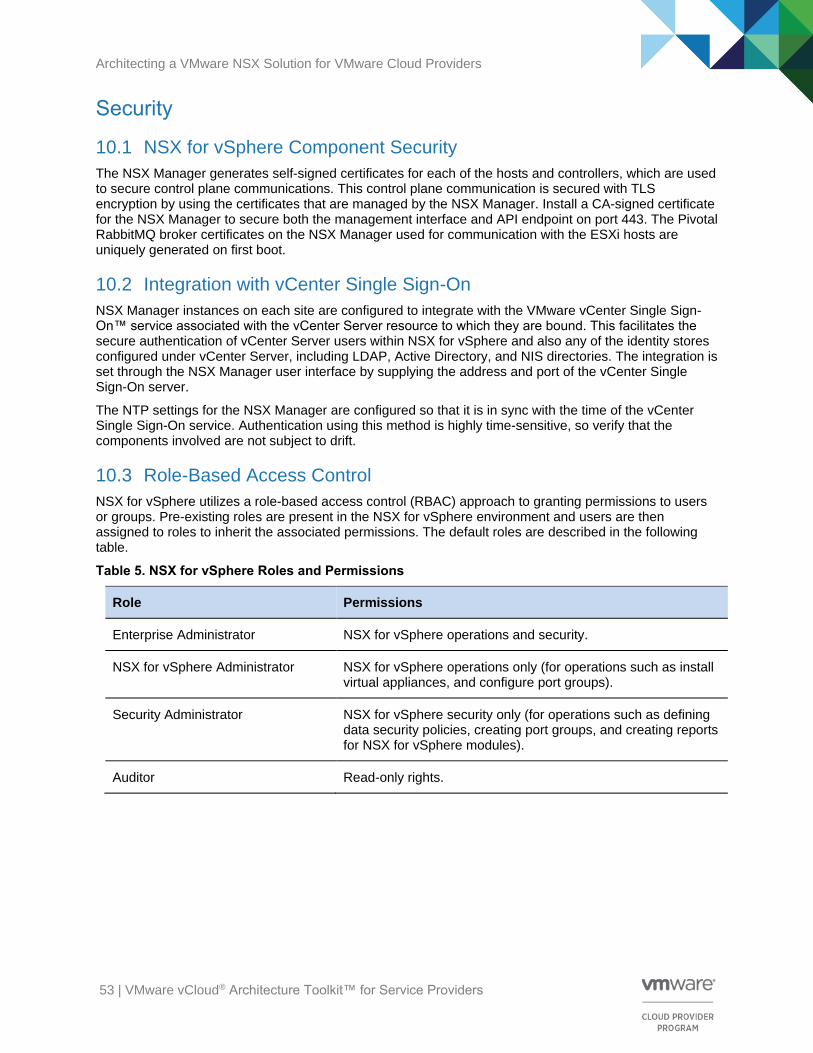
Architecting a VMware NSX Solution for VMware Cloud Providers
53 | VMware vCloud® Architecture Toolkit™ for Service Providers
Security
10.1 NSX for vSphere Component Security
The NSX Manager generates self-signed certificates for each of the hosts and controllers, which are used to secure control plane communications. This control plane communication is secured with TLS encryption by using the certificates that are managed by the NSX Manager. Install a CA-signed certificate for the NSX Manager to secure both the management interface and API endpoint on port 443. The Pivotal RabbitMQ broker certificates on the NSX Manager used for communication with the ESXi hosts are uniquely generated on first boot.
10.2 Integration with vCenter Single Sign-On
NSX Manager instances on each site are configured to integrate with the VMware vCenter Single Sign-On™ service associated with the vCenter Server resource to which they are bound. This facilitates the secure authentication of vCenter Server users within NSX for vSphere and also any of the identity stores configured under vCenter Server, including LDAP, Active Directory, and NIS directories. The integration is set through the NSX Manager user interface by supplying the address and port of the vCenter Single Sign-On server.
The NTP settings for the NSX Manager are configured so that it is in sync with the time of the vCenter Single Sign-On service. Authentication using this method is highly time-sensitive, so verify that the components involved are not subject to drift.
10.3 Role-Based Access Control
NSX for vSphere utilizes a role-based access control (RBAC) approach to granting permissions to users or groups. Pre-existing roles are present in the NSX for vSphere environment and users are then assigned to roles to inherit the associated permissions. The default roles are described in the following table.
Table 5. NSX for vSphere Roles and Permissions
Role Permissions
Enterprise Administrator NSX for vSphere operations and security.
NSX for vSphere Administrator NSX for vSphere operations only (for operations such as install virtual appliances, and configure port groups).
Security Administrator NSX for vSphere security only (for operations such as defining data security policies, creating port groups, and creating reports for NSX for vSphere modules).
Auditor Read-only rights.

Architecting a VMware NSX Solution for VMware Cloud Providers
54 | VMware vCloud® Architecture Toolkit™ for Service Providers
In addition to granting permissions using roles, it is also necessary to specify the scope of access that the user or group will have to the system. The scope levels are shown in the following table.
Table 6. NSX for vSphere Permissions Scopes
Scope Description
No restriction Full access to the NSX for vSphere system.
Limit access scope Access only to a specified NSX Edge device.
Both the Enterprise Administrator and VMware NSX Administrator roles can be assigned only to vCenter Server resources. Their scope is global, so it is not possible to apply restrictions.
10.4 NSX for vSphere Hardening
This section provides high-level recommendations for the most effective methods of evaluating and securing the NSX for vSphere platform, data center, and cloud infrastructure built using NSX for vSphere, specifically v6.1. The recommendations are grouped in to the following categories:
• Common
• Management plane
• Control plane
• Data plane
Information for each of these categories is provided in the VMware NSX for vSphere Hardening Guide available at https://communities.vmware.com/docs/DOC-28142. This guide is intended for users in various roles, including network and security architects, security officers, virtual infrastructure administrators, cloud infrastructure architects, cloud administrators, cloud customers, cloud providers, and auditors. Additionally, individuals and organizations that are seeking a starting point for the network and security controls to consider when adopting or building a network and security infrastructure will find the recommendations helpful.
VMware engages with various partners to perform security assessments of the NSX for vSphere platform and specific design and architecture deployments. These assessments also focus on newer features such as the integration of software-defined networking (SDN) and software-defined data center (SDDC). The assessment of the NSX for vSphere platform is primarily focused on networking and security attacks, configuration issues, secure defaults, and protocols in use. Using a combination of targeted source code review, active and fuzz testing, as well as other methods, these assessments locate and determine whether any significant vulnerabilities exist. Left unchecked, many of these issues (separately, or in concert) could result in a complete data center compromise. So, keep in mind as you design data center and cloud architecture and system solutions that you must take the required steps and make the appropriate architectural design decisions to avoid or mitigate issues that might arise in your own environment.
Despite the inherent risks, software-defined networking paired with network and security virtualization offers a myriad of benefits and allows for entirely software-defined data centers, a key part of the VMware vision for current and future products. You must also address the potential and inherent risks of this new platform as you work with the VMware NSX platform technology.
One of the true values of software-defined networking and security is it allows agile movement of virtual machines and networks and security services between physical hosts and the data center as compared to physical networking. The dynamic nature of this technology requires that underlying hosts be fully connected at the physical and IP layer. With these new options for connectivity, however, also come some risks. All software has flaws, and the re-implementation of core networking protocols, parsers, and

Architecting a VMware NSX Solution for VMware Cloud Providers
55 | VMware vCloud® Architecture Toolkit™ for Service Providers
switching methods will repeat and likely inherit historic vulnerabilities from older methods of physical networking and security.
As an example, denial-of-service (DoS) attacks have become a much greater issue now. In the physical networking world, dedicated hardware handles much of the parsing and routing of packets. In a software networking and security world, it is the software component that must parse, reparse, perform table lookups, and generally be aware of encapsulation, fragmentation and so on, spending much more CPU time deciding how to handle each packet. A potential software bug in any stage of this packet handling can lead to resource exhaustion, software crashes, and other scenarios that result in DoS and possibly a loss of networking and security services for hundreds of hosts, and also might affect the entire data center.
Software-defined networking and security also extends traditional network and security attacks to multiple data centers. Traditionally local attacks, such as ARP spoofing, can now be conducted across Layer 3 networks in geographically diverse locations. Additionally, if any vulnerability in the software network and security stack allows these attacks to leak onto the physical network, physical hosts in multiple data centers affecting multiple customers can also be compromised.
In a very real sense, software-defined networking and security as it is currently designed relies on virtual machine containment. If a virtual machine escape is ever performed or if an attacker discovers a technique for sending un-encapsulated packets on physical networks, expected security will be lost. As described previously, every physical host must be completely connected at the IP and physical layer, exposing an extremely broad attack surface. Once an attacker has a method of sending and receiving data on this physical network, the attacker can move laterally between hosts unabated by firewalls or routers, as these are no longer security relevant devices. Software-defined networking and security is a powerful technology that is necessary for organizations and companies to take advantage of, now and in the future. However, like all software, software-defined networking and data centers can be fragile and networking and security vulnerabilities have broad ramifications not traditionally realized in physical networking platforms.
As you look at recurring weaknesses, these are good candidates for systematic fixes as well as areas that require additional testing. These can also be considered in secure guidelines and threat modeling. Consider the following: insufficient control, management and data plane security requirements– Much of the NSX for vSphere platform can be protected with TLSv1/SSL (if properly configured), but consistent usage and strong defaults are still elusive. When protecting the NSX Manager, as well as the management REST APIs, use TLS v1.2, because the control plane uses TLS in all other communications.

Architecting a VMware NSX Solution for VMware Cloud Providers
56 | VMware vCloud® Architecture Toolkit™ for Service Providers
Operational Considerations
11.1 NSX Manager Operational Considerations
The NSX Manager is the management plane virtual appliance that helps configure logical switches and connect virtual machines to these logical switches. It also provides the management user interface an entry point for the NSX API, which helps automate deployment and management of the logical networks through a cloud management platform. In the NSX for vSphere architecture, NSX Manager is tightly connected to the vCenter Server managing the compute infrastructure. In fact, there is a 1:1 relationship between the NSX Manager and vCenter Server and, upon installation, the NSX Manager registers with vCenter Server and injects a plug-in into the vSphere Web Client for consumption within the web management platform.
Figure 22. VMware NSX Management Plane

Architecting a VMware NSX Solution for VMware Cloud Providers
57 | VMware vCloud® Architecture Toolkit™ for Service Providers
11.1.1 NSX Manager General Operational Considerations
Check the release notes for current releases to see if any problem you are having has been resolved in a bug fix. Also, verify that the minimum system requirements are met when installing VMware NSX Manager. For more information, refer to the VMware NSX Installation and Upgrade Guide available at http://pubs.vmware.com/NSX-61/topic/com.vmware.ICbase/PDF/nsx_61_install.pdf.
Table 7. NSX Manager Minimum Requirements
Component Minimum
Memory 12 GB
Disk Space 60 GB
vCPU 4 vCPU
Verify that all required ports are open in NSX Manager.
Table 8. NSX Manager Required Open Ports
Port Required for
443/TCP Downloading the OVA file on the ESXi host for deployment
Using REST APIs
Using the NSX Manager user interface
80/TCP Initiating connection to the vSphere SDK
1234/TCP Communication between ESXi host and NSX Controller clusters
5671 RabbitMQ (messaging bus technology)
22/TCP Console access (SSH) to CLI. By default, this port is closed
11.1.2 NSX Manager Installation Considerations
• If configuring the Lookup service or vCenter Server fails, verify that the NSX Manager and Lookup service appliances are in time sync. Use the same NTP server configurations on both NSX Manager and the Lookup service. Also verify that DNS is properly configured. For more information, see Registering NSX Manager to vCenter Server or configuring the SSO Lookup Service fails (2102041) at http://kb.vmware.com/kb/2102041.
• Verify that the OVA file is getting installed correctly. If a VMware NSX OVA file cannot be installed, an error window in the vSphere Client notes the line where the failure occurred. Also verify and validate the MD5 checksum of the downloaded OVA/OVF file.
• Verify that the time on the ESXi hosts is in sync with NSX Manager.
• VMware recommends that you schedule a backup of the NSX Manager data and configuration after installing NSX Manager. For more information, see the “Backing Up NSX Manager Data” section of the VMware NSX Administration Guide at http://pubs.vmware.com/NSX-61/topic/com.vmware.ICbase/PDF/nsx_61_admin.pdf.

Architecting a VMware NSX Solution for VMware Cloud Providers
58 | VMware vCloud® Architecture Toolkit™ for Service Providers
11.1.3 NSX Manager Upgrade Considerations
• Before upgrading, check the latest interoperability information in the Product Interoperability Matrixes page.
• VMware recommends that you take a snapshot of NSX Manager prior to performing an upgrade. Verify that the snapshot is committed after you are satisfied with the upgrade. VMware also recommends that you back up your current configuration and download technical support logs before upgrading. For more information, see the “Operations and Management “section of the VMware NSX Administration Guide at http://pubs.vmware.com/NSX-61/topic/com.vmware.ICbase/PDF/nsx_61_admin.pdf.
• A forced resync with the vCenter Server might be required after an NSX Manager upgrade. To do this, log in to the NSX Manager web interface and select Manage vCenter Registration > NSX Management Service > Edit, and re-enter the password for the vCenter Server user name.
11.1.4 NSX Manager Performance Considerations
• Check that the minimum requirement of four vCPUs is met for the NSX Manager.
• Verify that the / partition is not running out of space. You can verify this by logging into the NSX
Manager console and typing the command df -h.
• Use the top command to check which processes are taking up CPU and memory on the NSX
Manager.
• If the NSX Manager encounters any OutOfMemoryErrors on the logs, verify that
/common/dumps/java.hprof file exists. If the java.hprof file exists, create a copy of this file
and include this with the NSX Tech Support Log bundle.
• Verify that there are no storage latency issues in the environment. Attempt to migrate the NSX Manager to another ESXi host as part of the troubleshooting. It might be worthwhile to confirm that the NSX Manager virtual machine appliance is not running on snapshot.
11.1.5 NSX Manager Connectivity Issue Considerations
• If NSX Manager is having connectivity issues, either with the vCenter Server or the ESXi host, log in to the NSX Manager command-line interface console and run the debug connection <IP-of-
ESXi-or-VC> command and examine the output. For more information, see Network Port
Requirements for VMware NSX for vSphere 6.x (2079386) at http://kb.vmware.com/kb/2079386.
• Verify that the Virtual Center Web management services is started and the browser is not in an error state. For more information, see Clicking NSX Home in the vSphere Web Client reports the error: NSX Manager Internal Error. Review the NSX Manager log for details or contact your administrator - Unexpected Status Code 503 (2091369) at http://kb.vmware.com/kb/2091369.
• Verify which port group and uplink NIC is being used by the NSX Manager using the esxtop
command on the ESXi host. Attempt to migrate the NSX Manager to another ESXi host as part of the troubleshooting. You can also check the NSX Manager virtual machine appliance Tasks and Events tab from the vSphere Web Client under the Monitor tab.
• If the NSX Manager is having connectivity issues with the vCenter Server, migrate the NSX Manager to the same ESXi host where the vCenter Server virtual machine is running to eliminate possible underlying physical network.
Note This only works if both virtual machines are on the same VLAN or port group.

Architecting a VMware NSX Solution for VMware Cloud Providers
59 | VMware vCloud® Architecture Toolkit™ for Service Providers
11.1.6 NSX Manager Log Location
To collect diagnostic information for NSX for vSphere
1. Log in to the NSX Manager virtual appliance, through a web browser. For example: http://NSX_Manager_IP.
2. Under NSX Manager Virtual Appliance Management, click Download Tech Support Log.
3. Click Download.
4. Click Save to download the log to your machine.
Note The log is compressed and has a.gz file extension.
To collect NSX Controller logs
1. Log in to vCenter Sever using the vSphere Web Client, through a web browser.
2. Click the Networking and Security icon.
3. Click the Installation link on the left pane.
4. Under the Manage tab, select the NSX Controller you want to download logs from.
5. Click Download Tech support logs.
To collect NSX Edge and distributed logical router logs
1. Log in to vCenter Sever using the vSphere Web Client, through a web browser.
2. Click the Networking and Security icon.
3. Click the Edges link in the left pane.
4. In the right pane, select the NSX Edge gateway you want to download logs from.
5. Click the Actions button and select Download Tech support logs.

Architecting a VMware NSX Solution for VMware Cloud Providers
60 | VMware vCloud® Architecture Toolkit™ for Service Providers
11.2 NSX Controller Operational Considerations
The NSX Controller cluster in the NSX for vSphere 6.x platform is the control plane component that is responsible in managing the switching and routing modules in the hypervisors. The controller cluster consists of controller nodes that manage specific logical switches. The use of a controller cluster in managing VXLAN based logical switches eliminates the need for multicast support from the physical network infrastructure. Customers now do not have to provision multicast group IP addresses and also do not need to enable PIM routing or IGMP snooping features on physical switches or routers.
11.2.1 General Considerations
Verify that there are a minimum of three NSX Controller nodes deployed in a cluster. NSX for vSphere 6.1.x supports only clusters with three nodes. NSX Controller nodes are deployed as virtual appliances from the NSX Manager user interface. Each appliance is characterized by an IP address used for all control plane interactions with configuration of 4 vCPUs and 4 GB of RAM and currently cannot be modified.
VMware recommends spreading the deployment of the cluster nodes across separate ESXi hosts for increased reliability so that the failure of a single ESXi host does not cause the loss of majority number in the cluster. VMware NSX does not currently provide any embedded capability to enforce this, so the recommendation is to leverage the native vSphere anti-affinity rules to avoid deploying more than one controller node on the same ESXi host. For more information on how to create a VM-to-VM anti-affinity rule, see the “Create a VM-VM Affinity Rule in the vSphere Web Client” section of the VMware vSphere Resource Management Guide.
Verify that all NSX Controller nodes display a Connected status. If any of the Controller nodes displays a Disconnected status, run the show control-cluster status command on all NSX Controller nodes
to verify a consistent state.
Table 9. NSX Controller Status
Type Status
Join status Join complete
Majority status Connected to cluster majority
Cluster ID Same information on all Controller nodes
In addition, check that all roles are consistent on all NSX Controller nodes.
Table 10. NSX Controller Node Role Status
Role Configured Status Active Status
api_provider enabled activated
persistence_server enabled activated
switch_manager enabled activated
logical_manager enabled activated
directory_server enabled activated

Architecting a VMware NSX Solution for VMware Cloud Providers
61 | VMware vCloud® Architecture Toolkit™ for Service Providers
• Verify that vnet-controller process is running. Run the show process command on all Controller
nodes and check that the java-dir-server service is running.
• Verify the system status and resource utilization for each NSX Controller. Run the show status
command ensuring load is optimal for all nodes.
• Verify the cluster history and check that there is no sign of host connection flapping, VNI join failures, or abnormal cluster membership changes. Run the show control-cluster history command.
• Verify that VXLAN Network Identifier (VNI) is configured. For more information, see the “VXLAN Preparation Steps” section of the VMware VXLAN Deployment Guide at https://www.vmware.com/resources/techresources/10356.
• Verify that SSL is enabled on the NSX Controller cluster. Run the show log
cloudnet/cloudnet_java-vnet-controller*.log filtered-by sslEnabled command
on each of the NSX Controller nodes.
• Check for host connectivity errors. Run the show log cloudnet/cloudnet_java-vnet-
controller*.log filtered-by host_IP command on each of the NSX Controller nodes.
• Check for any abnormal error statistics. Run the following commands on each of the NSX Controller nodes:
o show control-cluster core stats: overall stats
o show control-cluster core stats-sample: latest stats samples
o show control-cluster core connection-stats <ip>: per connection stats
• Verify logical switch/router message statistics or high message rate. Run these commands on each of the NSX Controller nodes:
o show control-cluster logical-switches stats
o show control-cluster logical-routers stats
o show control-cluster logical-switches stats-sample
o show control-cluster logical-routers stats-sample
o show control-cluster logical-switches vni-stats <vni>
o show control-cluster logical-switches vni-stats-sample <vni>
o show control-cluster logical-switches connection-stats <ip>
o show control-cluster logical-routers connection-stats <ip>
For more information, see the VMware NSX Command Line Interface Reference Guide at http://pubs.vmware.com/NSX-6/topic/com.vmware.ICbase/PDF/nsx_60_cli.pdf.
• Verify that your environment is not experiencing any high storage latencies. Zookeeper logs these messages when storage latencies are greater than one second. (See the symptoms section when running the command show log cloudnet/cloudnet_java-zookeeper*.log filtered-by
fsync .) However, for the VMware NSX for vSphere 6.x control cluster, these are only a concern if
the latencies are greater than 10 seconds. VMware recommends dedicating a LUN specifically for the control-cluster and/or moving the storage array closer to the controller cluster in terms of latencies.

Architecting a VMware NSX Solution for VMware Cloud Providers
62 | VMware vCloud® Architecture Toolkit™ for Service Providers
11.2.2 NSX Distributed Firewall Log Location
To collect NSX Controller logs
1. Log in to vCenter Sever using the vSphere Web Client.
2. Click the Networking and Security icon.
3. Click the Installation link on the left pane.
4. Under the Manage tab, select the NSX Controller you want to download logs from.
5. Click Download Tech support logs.
11.3 NSX Distributed Firewall Operational Considerations
NSX distributed firewall is a hypervisor kernel-embedded firewall that provides visibility and control for virtualized workloads and networks. You can create access control policies based on vCenter Server objects such as data centers and clusters, virtual machine names and tags, network constructs such as IP/VLAN/VXLAN addresses, and user group identity from Active Directory. Consistent access control policy is now enforced when a virtual machine is moved using vSphere vMotion across physical hosts without the need to rewrite firewall rules. Because distributed firewall is hypervisor embedded, it delivers close to line rate throughput to enable higher workload consolidation on physical servers. The distributed nature of the firewall provides a scale-out architecture that automatically extends firewall capacity when additional hosts are added to a data center.
11.3.1 VMware NSX Distributed Firewall General Operational Considerations
Consider the following VMware NSX distributed firewall operational guidelines:
• Verify that the distributed firewall VIBs have been successfully installed on each of the ESXi hosts in the cluster. To do this, on each of the ESXi hosts that are on the cluster, run this command:
esxcli software vib list
• Verify the vShield-Stateful-Firewall service is in a running state. To do this, run this command:
/etc/init.d/vShield-Stateful-Firewall status
• Verify that the message bus is communicating properly with the NSX Manager.
Note The process is automatically launched by the watchdog script and restarts the process if it terminates for an unknown reason. Run this command on each of the ESXi hosts on the cluster:
ps |grep vsfwd
• Verify that port 5671 is opened for communication in the firewall configuration. You can validate that there is an active messaging bus connection by running this command on each of the ESXi hosts on the cluster:
esxcli network ip connection list |grep 5671
• Verify that the firewall rules have been deployed on a host and are being applied to virtual machines as follows:
a. Log in as root to the ESXi host through SSH.
b. Run the summarize-dvfilter command.
c. Run the vsipioctl getfwrules -f <name> command.
d. Run the vsipioctl getaddrsets -f <name> command.
Note

Architecting a VMware NSX Solution for VMware Cloud Providers
63 | VMware vCloud® Architecture Toolkit™ for Service Providers
• Verify that VMware Tools is running on the virtual machines if firewall rules do not use IP addresses. For more information, see Distributed Firewall Rules in VMware NSX for vSphere 6.0.x continues to apply with virtual machines even if VMware Tools is stopped or removed (2084048) at http://kb.vmware.com/kb/2084048.
• The distributed firewall is activated as soon as the host preparation process is completed. If a virtual machine needs no distributed firewall service at all, it can be added in the exclusion list functionality (by default, NSX Manager, NSX Controllers and NSX Edge services gateways are automatically excluded from the distributed firewall function). There is a possibility that the vCenter Server access will be blocked after creating a Deny All rule in the distributed firewall.
For more information, see vCenter Server access gets blocked after creating a Deny All rule in NSX Distributed Firewall (DFW) (2079620) at http://kb.vmware.com/kb/2079620.
11.3.2 VMware NSX Distributed Firewall Log Location
VMware NSX for vSphere 6.0.x:
• /var/log/vmkernel.log file on the ESXi host.
• /var/log/vsfwd.log file on the ESXi host.
VMware NSX for vSphere 6.1.x and later:
• /var/log/vmkernel.log file on the ESXi host.
• /var/log/dfwpktlogs.log file on the ESXi host
• /var/log/vsfwd.log file on the ESXi host
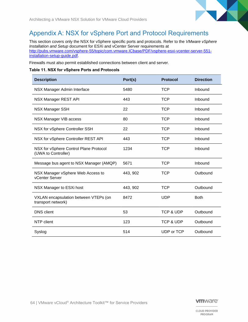
Architecting a VMware NSX Solution for VMware Cloud Providers
64 | VMware vCloud® Architecture Toolkit™ for Service Providers
Appendix A: NSX for vSphere Port and Protocol Requirements This section covers only the NSX for vSphere specific ports and protocols. Refer to the VMware vSphere Installation and Setup document for ESXi and vCenter Server requirements at http://pubs.vmware.com/vsphere-55/topic/com.vmware.ICbase/PDF/vsphere-esxi-vcenter-server-551-installation-setup-guide.pdf.
Firewalls must also permit established connections between client and server.
Table 11. NSX for vSphere Ports and Protocols
Description Port(s) Protocol Direction
NSX Manager Admin Interface 5480 TCP Inbound
NSX Manager REST API 443 TCP Inbound
NSX Manager SSH 22 TCP Inbound
NSX Manager VIB access 80 TCP Inbound
NSX for vSphere Controller SSH 22 TCP Inbound
NSX for vSphere Controller REST API 443 TCP Inbound
NSX for vSphere Control Plane Protocol (UWA to Controller)
1234 TCP Inbound
Message bus agent to NSX Manager (AMQP) 5671 TCP Inbound
NSX Manager vSphere Web Access to vCenter Server
443, 902 TCP Outbound
NSX Manager to ESXi host 443, 902 TCP Outbound
VXLAN encapsulation between VTEPs (on transport network)
8472 UDP Both
DNS client 53 TCP & UDP Outbound
NTP client 123 TCP & UDP Outbound
Syslog 514 UDP or TCP Outbound
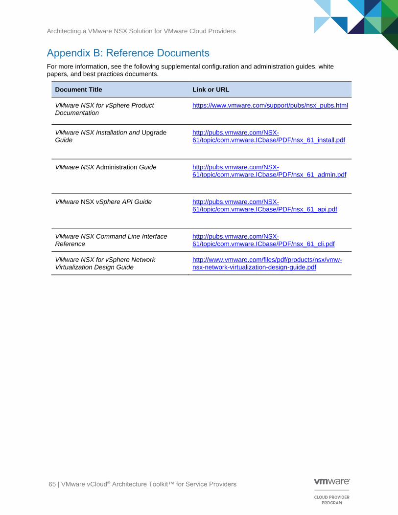
Architecting a VMware NSX Solution for VMware Cloud Providers
65 | VMware vCloud® Architecture Toolkit™ for Service Providers
Appendix B: Reference Documents For more information, see the following supplemental configuration and administration guides, white papers, and best practices documents.
Document Title Link or URL
VMware NSX for vSphere Product Documentation
https://www.vmware.com/support/pubs/nsx_pubs.html
VMware NSX Installation and Upgrade Guide
http://pubs.vmware.com/NSX-61/topic/com.vmware.ICbase/PDF/nsx_61_install.pdf
VMware NSX Administration Guide
http://pubs.vmware.com/NSX-61/topic/com.vmware.ICbase/PDF/nsx_61_admin.pdf
VMware NSX vSphere API Guide
http://pubs.vmware.com/NSX-61/topic/com.vmware.ICbase/PDF/nsx_61_api.pdf
VMware NSX Command Line Interface Reference
http://pubs.vmware.com/NSX-61/topic/com.vmware.ICbase/PDF/nsx_61_cli.pdf
VMware NSX for vSphere Network Virtualization Design Guide
http://www.vmware.com/files/pdf/products/nsx/vmw-nsx-network-virtualization-design-guide.pdf