architect tm - audiocontrol · architect model 1160/1161 16 channel power amplifier speaker...
TRANSCRIPT
Architect Model 1160/1161
16 channel Power Amplifier Speaker Optimizer ethernet interface
Professional installer’s consciousness Guide
22410 70th Avenue West Mountlake Terrace, WA 98043 USA 425-775-8461 • Fax 425-778-3166 www.audiocontrol.com
®For Those Who Consider Perfection Possible®
©2007. All rights reserved.
tm
®
important information
Dealer Name ________________________________________
Date installed _______________________________________
Serial Number _______________________________________
ethernet MAc Address _______________________________
iP Address Dynamic / Static ___________________________
ArchitectModel 1160/1161
installer’s Guide
™
cONteNtSArchitecttm Product Highlights. . . . . . . . . . . . . . . . . . . . . . . . . . . 2
Experienced Installer’s Quick Hook-Up Guide . . . . . . . . . . . . . . 3
A Guided Tour Of the Architect™. . . . . . . . . . . . . . . . . . . . . . . . 4
Hooking Up Your System . . . . . . . . . . . . . . . . . . . . . . . . . . . . . . 7
Installation: The Long Version. . . . . . . . . . . . . . . . . . . . . . . . . . . 8 Placement . . . . . . . . . . . . . . . . . . . . . . . . . . . . . . . . . . . . . . . 8 Power . . . . . . . . . . . . . . . . . . . . . . . . . . . . . . . . . . . . . . . . . . 9 Remote Power Control . . . . . . . . . . . . . . . . . . . . . . . . . . . . . 9 Audio Hook-Up . . . . . . . . . . . . . . . . . . . . . . . . . . . . . . . . . 10 Speaker Hook-Up . . . . . . . . . . . . . . . . . . . . . . . . . . . . . . . . 13
Equalizing the System . . . . . . . . . . . . . . . . . . . . . . . . . . . . . . . . 14
Equalization Controls. . . . . . . . . . . . . . . . . . . . . . . . . . . . . . . . . 15
A Short Introduction To Equalizers And Acoustics . . . . . . . . . . 16
Audio Analysis Using Pink Noise . . . . . . . . . . . . . . . . . . . . . . . 17
What’s Inside . . . . . . . . . . . . . . . . . . . . . . . . . . . . . . . . . . . . . . . 18 Patented Intelligent Power Supply . . . . . . . . . . . . . . . . . . . 18 Lightdrive Protection System. . . . . . . . . . . . . . . . . . . . . . . 18
Using the Ethernet Port . . . . . . . . . . . . . . . . . . . . . . . . . . . . . . . 19
Troubleshooting . . . . . . . . . . . . . . . . . . . . . . . . . . . . . . . . . . . . . 22
A Brazen Plug For Other AudioControl Products . . . . . . . . . . . 24
Appendices Appendix A Bridging The Architect . . . . . . . . . . . . . . . . . . . . . . . . . . 25 Appendix B Using the Ethernet-Based Automation Systems . . . . . . . 26
The Warranty . . . . . . . . . . . . . . . . . . . . . . . . . . . . . . . . . . . . . . . 29
Service Information . . . . . . . . . . . . . . . . . . . . . . . . . . . . . . . . . . 30
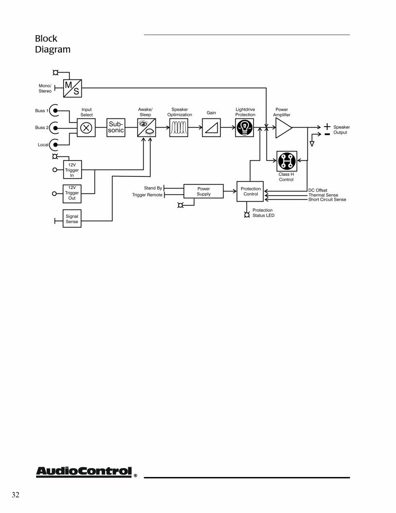
Block Diagram. . . . . . . . . . . . . . . . . . . . . . . . . . . . . . . . . . . . . . 31
Specifications . . . . . . . . . . . . . . . . . . . . . . . . . . . . . . . . . . . . . . . 32
®
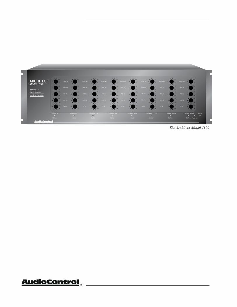
The Architect Model 1160
ArchitectModel 1160/1161
installer’s Guide
™
Product Highlights
1
Congratulations! You are now installing a component which will dramatically
improve the performance of any distributed audio system, espe-cially those utilizing in-wall speakers. The Architect™ Model 1100 Series are American-designed and built, “set and forget” components which will provide a lifetime of trouble-free service for your multi-room audio system.
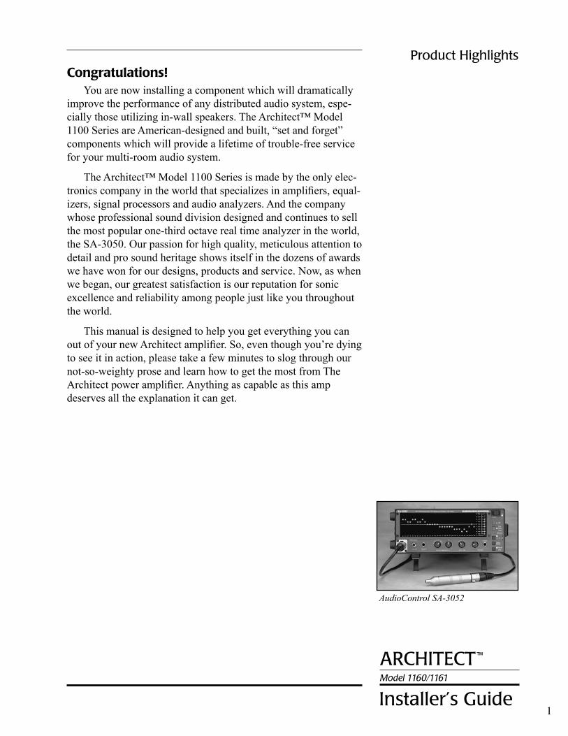
The Architect™ Model 1100 Series is made by the only elec-tronics company in the world that specializes in amplifiers, equal-izers, signal processors and audio analyzers. And the company whose professional sound division designed and continues to sell the most popular one-third octave real time analyzer in the world, the SA-3050. Our passion for high quality, meticulous attention to detail and pro sound heritage shows itself in the dozens of awards we have won for our designs, products and service. Now, as when we began, our greatest satisfaction is our reputation for sonic excellence and reliability among people just like you throughout the world.
This manual is designed to help you get everything you can out of your new Architect amplifier. So, even though you’re dying to see it in action, please take a few minutes to slog through our not-so-weighty prose and learn how to get the most from The Architect power amplifier. Anything as capable as this amp deserves all the explanation it can get.
AudioControl SA-3052
®
Product Highlights
2
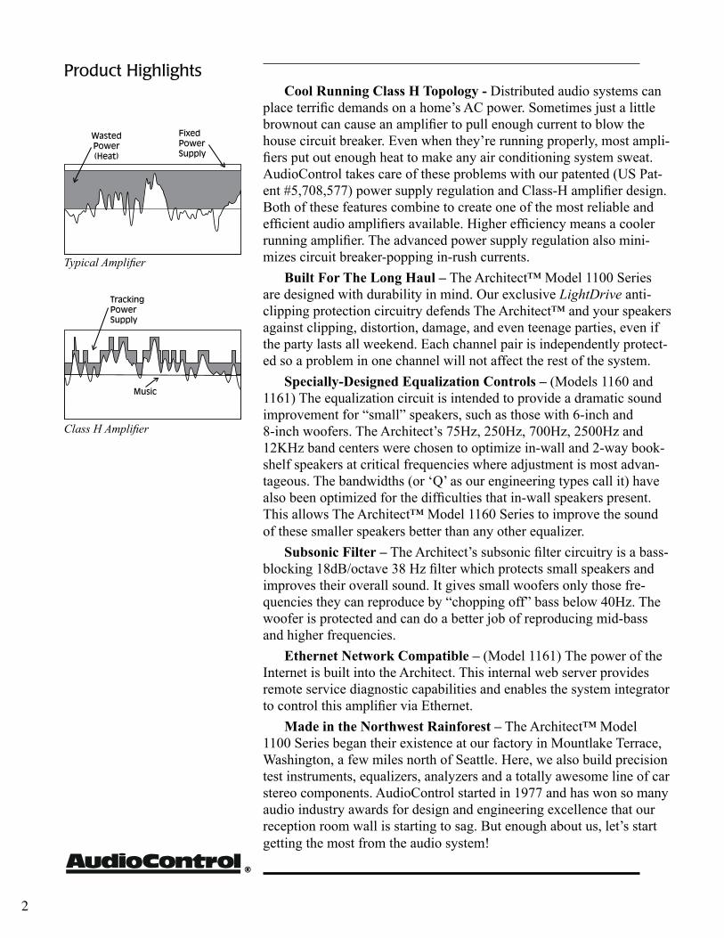
Cool Running Class H Topology - Distributed audio systems can place terrific demands on a home’s AC power. Sometimes just a little brownout can cause an amplifier to pull enough current to blow the house circuit breaker. Even when they’re running properly, most ampli-fiers put out enough heat to make any air conditioning system sweat. AudioControl takes care of these problems with our patented (US Pat-ent #5,708,577) power supply regulation and Class-H amplifier design. Both of these features combine to create one of the most reliable and efficient audio amplifiers available. Higher efficiency means a cooler running amplifier. The advanced power supply regulation also mini-mizes circuit breaker-popping in-rush currents.
Built For The Long Haul – The Architect™ Model 1100 Series are designed with durability in mind. Our exclusive LightDrive anti-clipping protection circuitry defends The Architect™ and your speakers against clipping, distortion, damage, and even teenage parties, even if the party lasts all weekend. Each channel pair is independently protect-ed so a problem in one channel will not affect the rest of the system.
Specially-Designed Equalization Controls – (Models 1160 and 1161) The equalization circuit is intended to provide a dramatic sound improvement for “small” speakers, such as those with 6-inch and 8-inch woofers. The Architect’s 75Hz, 250Hz, 700Hz, 2500Hz and 12KHz band centers were chosen to optimize in-wall and 2-way book-shelf speakers at critical frequencies where adjustment is most advan-tageous. The bandwidths (or ‘Q’ as our engineering types call it) have also been optimized for the difficulties that in-wall speakers present. This allows The Architect™ Model 1160 Series to improve the sound of these smaller speakers better than any other equalizer.
Subsonic Filter – The Architect’s subsonic filter circuitry is a bass-blocking 18dB/octave 38 Hz filter which protects small speakers and improves their overall sound. It gives small woofers only those fre-quencies they can reproduce by “chopping off” bass below 40Hz. The woofer is protected and can do a better job of reproducing mid-bass and higher frequencies.
Ethernet Network Compatible – (Model 1161) The power of the Internet is built into the Architect. This internal web server provides remote service diagnostic capabilities and enables the system integrator to control this amplifier via Ethernet.
Made in the Northwest Rainforest – The Architect™ Model 1100 Series began their existence at our factory in Mountlake Terrace, Washington, a few miles north of Seattle. Here, we also build precision test instruments, equalizers, analyzers and a totally awesome line of car stereo components. AudioControl started in 1977 and has won so many audio industry awards for design and engineering excellence that our reception room wall is starting to sag. But enough about us, let’s start getting the most from the audio system!
Typical Amplifier
Class H Amplifier
ArchitectModel 1160/1161
installer’s Guide
™
Quick Hook-Up Guide
3
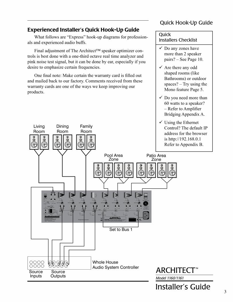
Experienced Installer’s Quick Hook-Up GuideWhat follows are “Express” hook-up diagrams for profession-
als and experienced audio buffs.
Final adjustment of The Architect™ speaker optimizer con-trols is best done with a one-third octave real time analyzer and pink noise test signal, but it can be done by ear, especially if you desire to emphasize certain frequencies.
One final note: Make certain the warranty card is filled out and mailed back to our factory. Comments received from these warranty cards are one of the ways we keep improving our products.
Quick installers checklist
Do any zones have more than 2 speaker pairs? – See Page 10.
Are there any odd shaped rooms (like Bathrooms) or outdoor spaces? – Try using the Mono feature Page 5.
Do you need more than 60 watts to a speaker? – Refer to Amplifier Bridging Appendix A.
Using the Ethernet Control? The default IP address for the browser is http://192.168.0.1 Refer to Appendix B.
®
Front Panel
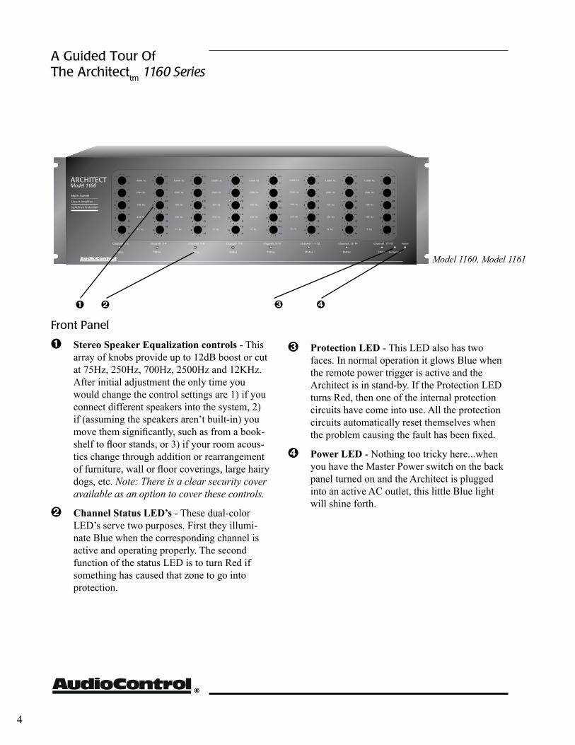
Ê Stereo Speaker Equalization controls - This array of knobs provide up to 12dB boost or cut at 75Hz, 250Hz, 700Hz, 2500Hz and 12KHz. After initial adjustment the only time you would change the control settings are 1) if you connect different speakers into the system, 2) if (assuming the speakers aren’t built-in) you move them significantly, such as from a book-shelf to floor stands, or 3) if your room acous-tics change through addition or rearrangement of furniture, wall or floor coverings, large hairy dogs, etc. Note: There is a clear security cover available as an option to cover these controls.
Ë Channel Status LED’s - These dual-color LED’s serve two purposes. First they illumi-nate Blue when the corresponding channel is active and operating properly. The second function of the status LED is to turn Red if something has caused that zone to go into protection.
4
Ì Protection LED - This LED also has two faces. In normal operation it glows Blue when the remote power trigger is active and the Architect is in stand-by. If the Protection LED turns Red, then one of the internal protection circuits have come into use. All the protection circuits automatically reset themselves when the problem causing the fault has been fixed.
Í Power LED - Nothing too tricky here...when you have the Master Power switch on the back panel turned on and the Architect is plugged into an active AC outlet, this little Blue light will shine forth.
ÌÍÊ Ë
Model 1160, Model 1161
A Guided tour Of the Architecttm 1160 Series
ArchitectModel 1160/1161
installer’s Guide
™
5
A Guided tour Of the Architecttm 1160 Series
more rear panel features on the next page
Ì Í Ð Ñ
Ê ËÏ Î
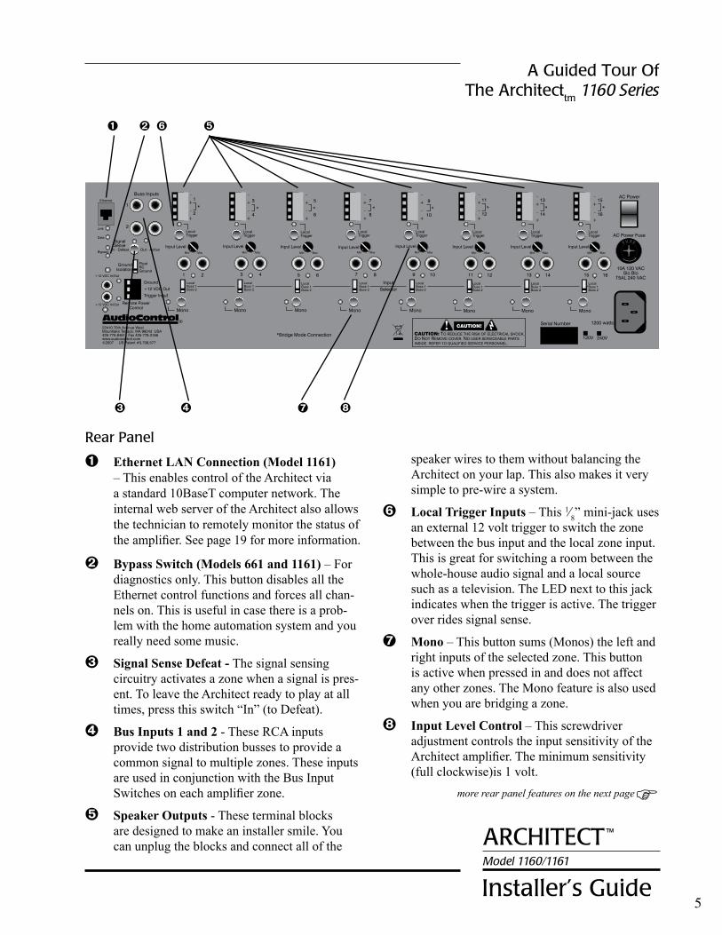
rear Panel
Ê Ethernet LAN Connection (Model 1161) – This enables control of the Architect via a standard 10BaseT computer network. The internal web server of the Architect also allows the technician to remotely monitor the status of the amplifier. See page 19 for more information.
Ë Bypass Switch (Models 661 and 1161) – For diagnostics only. This button disables all the Ethernet control functions and forces all chan-nels on. This is useful in case there is a prob-lem with the home automation system and you really need some music.
Ì Signal Sense Defeat - The signal sensing circuitry activates a zone when a signal is pres-ent. To leave the Architect ready to play at all times, press this switch “In” (to Defeat).
Í Bus Inputs 1 and 2 - These RCA inputs provide two distribution busses to provide a common signal to multiple zones. These inputs are used in conjunction with the Bus Input Switches on each amplifier zone.
Î Speaker Outputs - These terminal blocks are designed to make an installer smile. You can unplug the blocks and connect all of the
speaker wires to them without balancing the Architect on your lap. This also makes it very simple to pre-wire a system.
Ï Local Trigger Inputs – This 1⁄8” mini-jack uses an external 12 volt trigger to switch the zone between the bus input and the local zone input. This is great for switching a room between the whole-house audio signal and a local source such as a television. The LED next to this jack indicates when the trigger is active. The trigger over rides signal sense.
Ð Mono – This button sums (Monos) the left and right inputs of the selected zone. This button is active when pressed in and does not affect any other zones. The Mono feature is also used when you are bridging a zone.
Ñ Input Level Control – This screwdriver adjustment controls the input sensitivity of the Architect amplifier. The minimum sensitivity (full clockwise)is 1 volt.
®
6
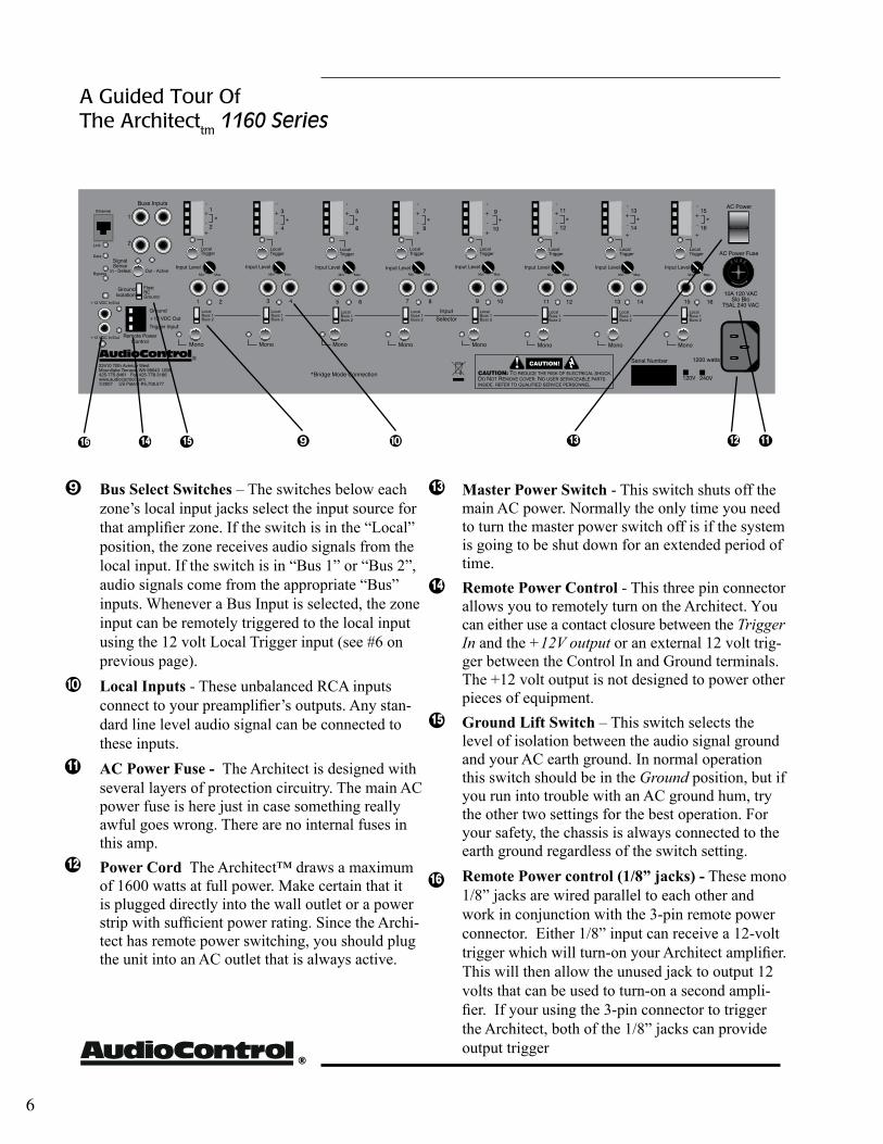
Ò BusSelectSwitches – The switches below each zone’s local input jacks select the input source for that amplifier zone. If the switch is in the “Local” position, the zone receives audio signals from the local input. If the switch is in “Bus 1” or “Bus 2”, audio signals come from the appropriate “Bus” inputs. Whenever a Bus Input is selected, the zone input can be remotely triggered to the local input using the 12 volt Local Trigger input (see #6 on previous page).
Ó LocalInputs - These unbalanced RCA inputs connect to your preamplifier’s outputs. Any stan-dard line level audio signal can be connected to these inputs.
ACPowerFuse- The Architect is designed with several layers of protection circuitry. The main AC power fuse is here just in case something really awful goes wrong. There are no internal fuses in this amp.
PowerCord The Architect™ draws a maximum of 1600 watts at full power. Make certain that it is plugged directly into the wall outlet or a power strip with sufficient power rating. Since the Archi-tect has remote power switching, you should plug the unit into an AC outlet that is always active.
MasterPowerSwitch - This switch shuts off the main AC power. Normally the only time you need to turn the master power switch off is if the system is going to be shut down for an extended period of time.
RemotePowerControl - This three pin connector allows you to remotely turn on the Architect. You can either use a contact closure between the Trigger In and the +12V output or an external 12 volt trig-ger between the Control In and Ground terminals. The +12 volt output is not designed to power other pieces of equipment.
GroundLiftSwitch – This switch selects the level of isolation between the audio signal ground and your AC earth ground. In normal operation this switch should be in the Ground position, but if you run into trouble with an AC ground hum, try the other two settings for the best operation. For your safety, the chassis is always connected to the earth ground regardless of the switch setting.
RemotePowercontrol(1/8”jacks)- These mono 1/8” jacks are wired parallel to each other and work in conjunction with the 3-pin remote power connector. Either 1/8” input can receive a 12-volt trigger which will turn-on your Architect amplifier. This will then allow the unused jack to output 12 volts that can be used to turn-on a second ampli-fier. If your using the 3-pin connector to trigger the Architect, both of the 1/8” jacks can provide output trigger
A Guided Tour Of The Architecttm 1160 Series
ÒÓ 111514 13 12
12
11
13
14
15
16
16
ArchiTecTModel 1160/1161
installer’s Guide
™
7
Hooking Up Your SystemWhat you’ll need:
1. The Architect™ Model 1100 Series Amplifier.
2. RCA audio hook-up cables.
3. Small blade screwdriver for terminal blocks
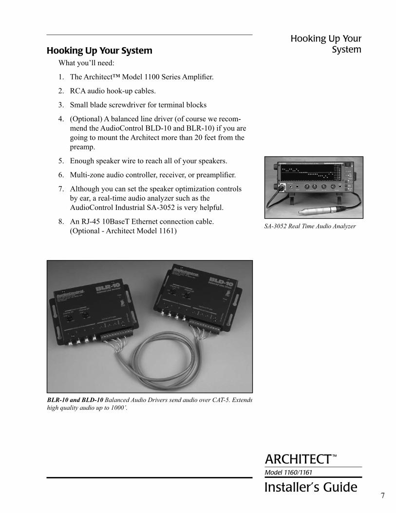
4. (Optional) A balanced line driver (of course we recom- mend the AudioControl BLD-10 and BLR-10) if you are going to mount the Architect more than 20 feet from the preamp.
5. Enough speaker wire to reach all of your speakers.
6. Multi-zone audio controller, receiver, or preamplifier.
7. Although you can set the speaker optimization controls by ear, a real-time audio analyzer such as the AudioControl Industrial SA-3052 is very helpful.
8. An RJ-45 10BaseT Ethernet connection cable. (Optional - Architect Model 1161)
Hooking Up Your System
BLR-10 and BLD-10 Balanced Audio Drivers send audio over CAT-5. Extends high quality audio up to 1000’.
SA-3052 Real Time Audio Analyzer
®
Installation: The Long Version
8
Installation: The Long VersionWhat follows is a step-by-step guide to integrating the Ar-
chitect into your multi-zone system. If it seems overly detailed, please forgive us. We would rather tell you too much than too little.
First, check your new Architect for any shipping damage. We pack ‘em pretty securely, but it’s a vicious world out there and anything can happen between us building them here in Mountlake Terrace, Washington and your installation.
PaPerwork
Yes, filling out the warranty registration card is about as excit-ing as cleaning out your sock drawer, but we’d definitely like the card back after you’ve hooked up the Architect and played with it a while. We DO read each and every incoming card and react to your suggestions. That’s how great products like this are created.
Next, record the serial number on the sales receipt and make certain the home owner puts it away in a safe place. Stashing the receipt away is very important in the unlikely event that your Architect ever needs servicing, or…well things do happen…you need to prove to an insurance adjuster that something as great as the Architect was installed in the system.
PLacemenT
The Architect Model 1100 Series is a very efficient amplifier, but it does need some breathing room to operate properly. Make certain that the air vents on the rear and sides of the Architect are not blocked and have at least ½” of air space. Also make certain that heat sensitive components such as CD or Tape players are not directly on top of the Architect. Just as a reminder, you should avoid putting any leaky pipes above the audio equipment stack.
A benefit of having remote power control on the Architect is that you can install it in another area of the house (such as a base-ment or utility room) away from the main component stack. Make certain that you use a good quality audio line driver to extend the RCA cables if you choose this type of installation.
Power
Under normal operating conditions, the Architect Model 1100 Series amplifiers can draw up to 1600 watts of AC power. Don’t plug it into a switched outlet on your system unless you are certain that it can handle the power rating. Also, please don’t cut off the ground pin on the power connector. It is an important
ArchiTecTModel 1160/1161
installer’s Guide
™
Installation: The Long Version
9
safety feature. If you need to plug it into a two prong outlet, use a ground adapter (and connect the ground on it). If you have a ground noise problem, try the ground lift switch on the rear panel.
remoTe Power conTroL
The Architect has several means of power control:
•MainACPowerswitch- This is the master control and must be turned ON for the Architect to function. When the main power switch is on, the blue Power LED on the front panel lights up. Normally the only time that you would need to turn the AC power switch off is when the system is going to be unused for an extended period.
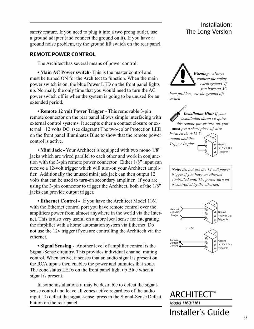
•Remote12voltPowerTrigger- This removable 3-pin remote connector on the rear panel allows simple interfacing with external control systems. It accepts either a contact closure or ex-ternal +12 volts DC. (see diagram) The two-color Protection LED on the front panel illuminates Blue to show that the remote power control is active.
•MiniJack- Your Architect is equipped with two mono 1/8” jacks which are wired parallel to each other and work in conjunc-tion with the 3-pin remote power connector. Either 1/8” input can receive a 12-volt trigger which will turn-on your Architect ampli-fier. Additionally the unused mini jack jack can then output 12 volts that can be used to turn-on secondary amplifier. If you are using the 3-pin connector to trigger the Architect, both of the 1/8” jacks can provide output trigger.
•EthernetControl- If you have the Architect Model 1161 with the Ethernet control port you have remote control over the amplifiers power from almost anywhere in the world via the Inter-net. This is also very useful on a more local sense for integrating the amplifier with a home automation system via Ethernet. Do not use the 12v trigger if you are controlling the Architech via the ethernet.
•SignalSensing- Another level of amplifier control is the Signal-Sense circuitry. This provides individual channel muting control. When active, it senses that an audio signal is present on the RCA inputs then enables the power and unmutes that zone. The zone status LEDs on the front panel light up Blue when a signal is present.
In some installations it may be desirable to defeat the signal-sense control and leave all zones active regardless of the audio input. To defeat the signal-sense, press in the Signal-Sense Defeat button on the rear panel
Installation Hint: If your installation doesn’t require
this remote power turn-on, you must put a short piece of wire
between the +12 V output and the Trigger In pins.
Warning - Always connect the safety
earth ground. If you have an AC
hum problem, use the ground lift switch
Note: Do not use the 12 volt power trigger if you have an ethernet controlled unit. The power turn on is controlled by the ethernet.
®
10
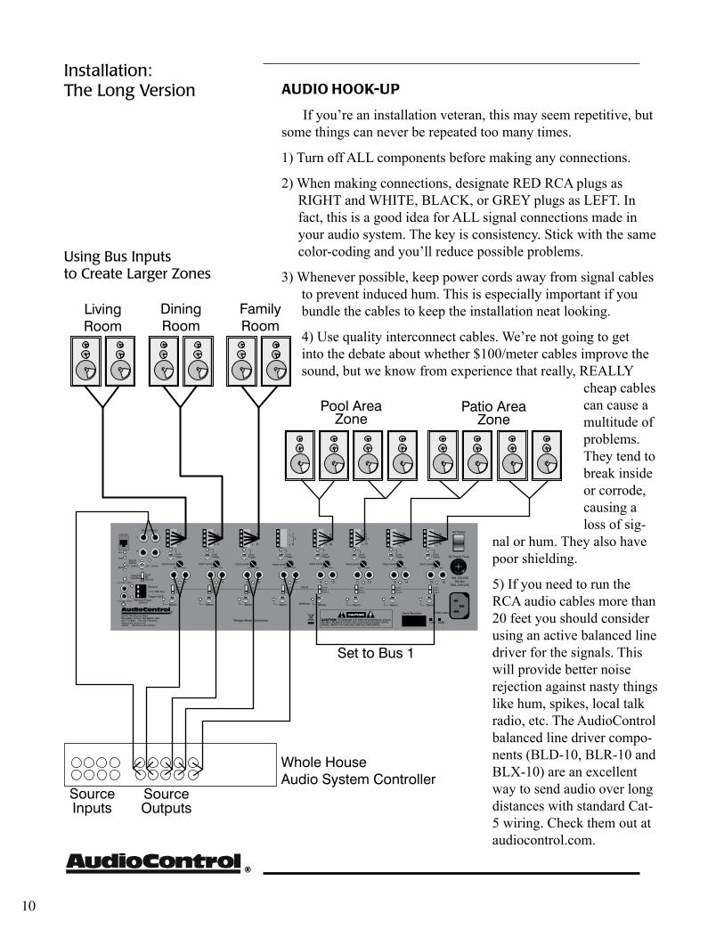
aUDIo Hook-UP
If you’re an installation veteran, this may seem repetitive, but some things can never be repeated too many times.
1) Turn off ALL components before making any connections.
2) When making connections, designate RED RCA plugs as RIGHT and WHITE, BLACK, or GREY plugs as LEFT. In fact, this is a good idea for ALL signal connections made in your audio system. The key is consistency. Stick with the same color-coding and you’ll reduce possible problems.
3) Whenever possible, keep power cords away from signal cables to prevent induced hum. This is especially important if you bundle the cables to keep the installation neat looking.
4) Use quality interconnect cables. We’re not going to get into the debate about whether $100/meter cables improve the sound, but we know from experience that really, REALLY
cheap cables can cause a multitude of problems. They tend to break inside or corrode, causing a loss of sig-
nal or hum. They also have poor shielding.
5) If you need to run the RCA audio cables more than 20 feet you should consider using an active balanced line driver for the signals. This will provide better noise rejection against nasty things like hum, spikes, local talk radio, etc. The AudioControl balanced line driver compo-nents (BLD-10, BLR-10 and BLX-10) are an excellent way to send audio over long distances with standard Cat-5 wiring. Check them out at audiocontrol.com.
Installation: The Long Version
Using Bus inputs to create Larger Zones

ArchiTecTModel 1160/1161
installer’s Guide
™
wHoLe HoUSe SYSTem wITH TUner onLY BackgroUnD mUSIc
11
Installation: The Long Version
®
12
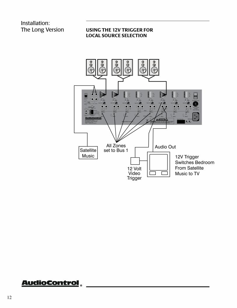
Installation: The Long Version USIng THe 12V TrIgger for
LocaL SoUrce SeLecTIon
ArchiTecTModel 1160/1161
installer’s Guide
™
SPeaker Hook-UP
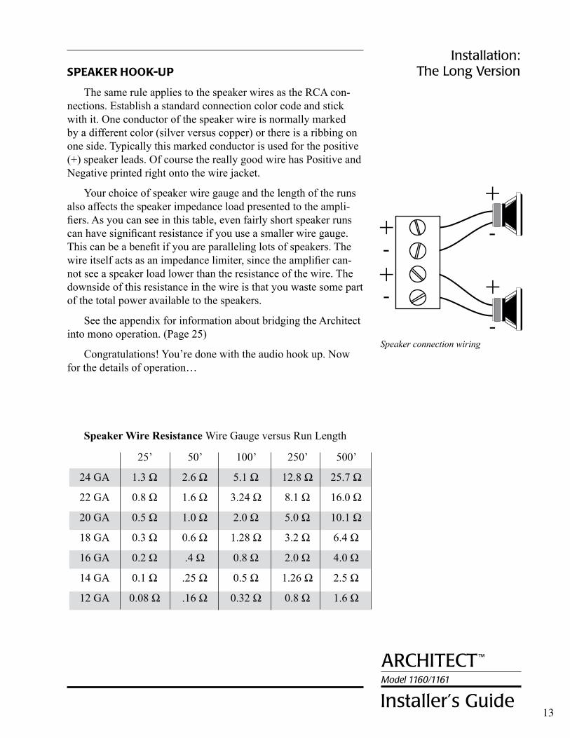
The same rule applies to the speaker wires as the RCA con-nections. Establish a standard connection color code and stick with it. One conductor of the speaker wire is normally marked by a different color (silver versus copper) or there is a ribbing on one side. Typically this marked conductor is used for the positive (+) speaker leads. Of course the really good wire has Positive and Negative printed right onto the wire jacket.
Your choice of speaker wire gauge and the length of the runs also affects the speaker impedance load presented to the ampli-fiers. As you can see in this table, even fairly short speaker runs can have significant resistance if you use a smaller wire gauge. This can be a benefit if you are paralleling lots of speakers. The wire itself acts as an impedance limiter, since the amplifier can-not see a speaker load lower than the resistance of the wire. The downside of this resistance in the wire is that you waste some part of the total power available to the speakers.
See the appendix for information about bridging the Architect into mono operation. (Page 25)
Congratulations! You’re done with the audio hook up. Now for the details of operation…
Speaker connection wiring
Installation: The Long Version
25’ 50’ 100’ 250’ 500’
24 GA 1.3 Ω 2.6 Ω 5.1 Ω 12.8 Ω 25.7 Ω
22 GA 0.8 Ω 1.6 Ω 3.24 Ω 8.1 Ω 16.0 Ω
20 GA 0.5 Ω 1.0 Ω 2.0 Ω 5.0 Ω 10.1 Ω
18 GA 0.3 Ω 0.6 Ω 1.28 Ω 3.2 Ω 6.4 Ω
16 GA 0.2 Ω .4 Ω 0.8 Ω 2.0 Ω 4.0 Ω
14 GA 0.1 Ω .25 Ω 0.5 Ω 1.26 Ω 2.5 Ω
12 GA 0.08 Ω .16 Ω 0.32 Ω 0.8 Ω 1.6 Ω
13
SpeakerWireResistanceWire Gauge versus Run Length
®
Equalizing the Systemequalizing the System
Before proceeding on to setting up the Speaker Optimization controls on the Architect, it’s a good idea to make sure that you have everything connected and working properly.
1. Double-check all connections. Make certain that all of the audio and speaker connections are firmly seated and tightened down.
2. Turn on your audio system. The Power LED on the Architect should be Blue, the Protection LED should be Blue (after a few seconds of Red on startup) and (unless you have defeated the Signal-Sense) the Channel Status LEDs should be off.
3. Start one of the audio sources playing and send that signal to the Architect (how you do this depends on your particular multi-room system). The zone status LED should illuminate Blue within one second after the music begins.
4. Check each speaker output zone to ensure that each one plays properly.
5. With all the speaker loads turned on, turn up the volume and make certain that the channel status LEDs on the Architect stay Blue. If they slowly toggle between Blue and Red, then there is either a short in the speaker wiring, or the combined speaker load is too low.
Congratulations! You’re ready to go on to setting the Speaker Optimization controls.
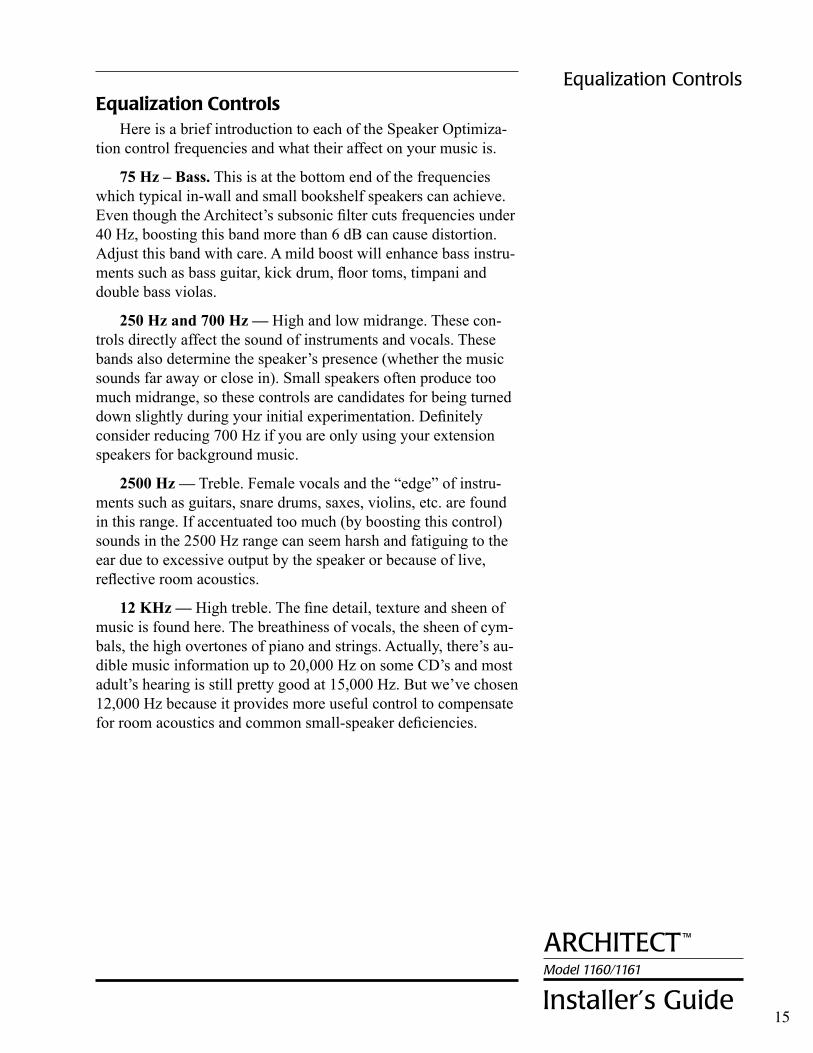
The following are examples of typical settings of the Architect™ Model 1160/1161 Series Speaker Optimizer controls. Naturally, the results of adjustments will vary depending on the individual acoustic environment, the type of speakers, and the personal preferences of the listener. These recommendations are not concrete, they are simply good starting points.
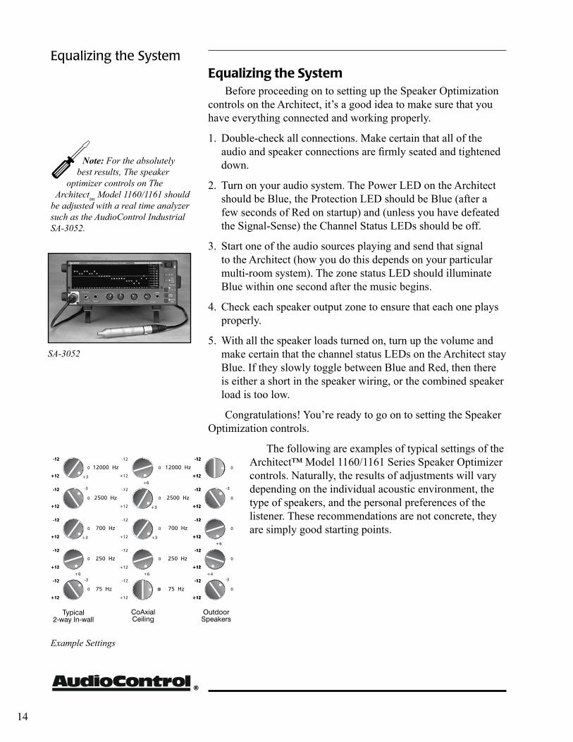
Note: For the absolutely best results, The speaker
optimizer controls on The Architecttm Model 1160/1161 should
be adjusted with a real time analyzer such as the AudioControl Industrial SA-3052.
14
Example Settings
SA-3052
ArchitectModel 1160/1161
installer’s Guide
™
Equalization ControlsHere is a brief introduction to each of the Speaker Optimiza-
tion control frequencies and what their affect on your music is.
75 Hz – Bass. This is at the bottom end of the frequencies which typical in-wall and small bookshelf speakers can achieve. Even though the Architect’s subsonic filter cuts frequencies under 40 Hz, boosting this band more than 6 dB can cause distortion. Adjust this band with care. A mild boost will enhance bass instru-ments such as bass guitar, kick drum, floor toms, timpani and double bass violas.
250 Hz and 700 Hz — High and low midrange. These con-trols directly affect the sound of instruments and vocals. These bands also determine the speaker’s presence (whether the music sounds far away or close in). Small speakers often produce too much midrange, so these controls are candidates for being turned down slightly during your initial experimentation. Definitely consider reducing 700 Hz if you are only using your extension speakers for background music.
2500 Hz — Treble. Female vocals and the “edge” of instru-ments such as guitars, snare drums, saxes, violins, etc. are found in this range. If accentuated too much (by boosting this control) sounds in the 2500 Hz range can seem harsh and fatiguing to the ear due to excessive output by the speaker or because of live, reflective room acoustics.
12 KHz — High treble. The fine detail, texture and sheen of music is found here. The breathiness of vocals, the sheen of cym-bals, the high overtones of piano and strings. Actually, there’s au-dible music information up to 20,000 Hz on some CD’s and most adult’s hearing is still pretty good at 15,000 Hz. But we’ve chosen 12,000 Hz because it provides more useful control to compensate for room acoustics and common small-speaker deficiencies.
Equalization Controls
15
®
A Short Introduction To Equalizers And AcousticsMagazine reviewers and audio system owners spend much
time critically appraising speakers and other stereo components. Unfortunately, a phenomenon that has a very large effect upon sound is not easily judged or changed. That effect is the ACOUS-TICS of the environment in which you are listening.
Room acoustics is a complicated subject about which entire textbooks have been written. We simply want you to be aware of a few basics that have a direct effect on real time audio analysis.
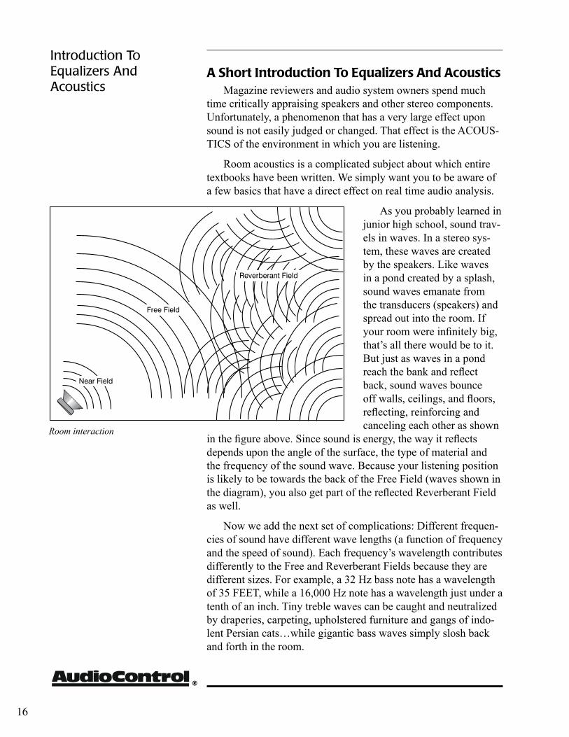
As you probably learned in junior high school, sound trav-els in waves. In a stereo sys-tem, these waves are created by the speakers. Like waves in a pond created by a splash, sound waves emanate from the transducers (speakers) and spread out into the room. If your room were infinitely big, that’s all there would be to it. But just as waves in a pond reach the bank and reflect back, sound waves bounce off walls, ceilings, and floors, reflecting, reinforcing and canceling each other as shown
in the figure above. Since sound is energy, the way it reflects depends upon the angle of the surface, the type of material and the frequency of the sound wave. Because your listening position is likely to be towards the back of the Free Field (waves shown in the diagram), you also get part of the reflected Reverberant Field as well.
Now we add the next set of complications: Different frequen-cies of sound have different wave lengths (a function of frequency and the speed of sound). Each frequency’s wavelength contributes differently to the Free and Reverberant Fields because they are different sizes. For example, a 32 Hz bass note has a wavelength of 35 FEET, while a 16,000 Hz note has a wavelength just under a tenth of an inch. Tiny treble waves can be caught and neutralized by draperies, carpeting, upholstered furniture and gangs of indo-lent Persian cats…while gigantic bass waves simply slosh back and forth in the room.
Introduction To Equalizers And Acoustics
16
Room interaction
ArchitectModel 1160/1161
installer’s Guide
™
Another set of variables is the shape and volume of your listening room. Large rooms require more bass energy to excite waves within them. Small rooms need less energy, but reflect it differently. And then there’s the fact that most rooms don’t have four walls anymore, but open into dining rooms, lofts, cathedral ceilings, etc. All of this means that predicting sound interaction patterns is very difficult due to the ir-regularities of the room shape.
As you can see, room acoustics is an important but complicated subject To learn more about room acoustics, get a copy of AudioCon-trol’s Technical Paper 107, “Small Room Acoustics De-Mythologized”. You can download this paper from www.audiocontrol.com or if you’re still into the printed page, call us and we’ll mail you a copy. The overall point that we’re trying to make is that the various rooms in your home function as gigantic mechanical equalizers, boosting or cutting certain frequencies depending on size, shape, volume, acoustic treatment and the position of the speakers.
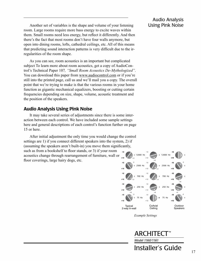
Audio Analysis Using Pink NoiseIt may take several series of adjustments since there is some inter-
action between each control. We have included some sample settings here and general descriptions of each control’s function further on page 15 or here.
After initial adjustment the only time you would change the control settings are 1) if you connect different speakers into the system, 2) if (assuming the speakers aren’t built-in) you move them significantly, such as from a bookshelf to floor stands, or 3) if your room acoustics change through rearrangement of furniture, wall or floor coverings, large hairy dogs, etc.
17
Audio Analysis Using Pink Noise
Example Settings
®
Amplifier without LightDrive
Amplifier with Lightdrive
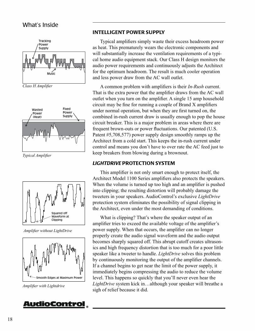
INTEllIgENT PowEr SUPPly
Typical amplifiers simply waste their excess headroom power as heat. This prematurely wears the electronic components and will substantially increase the ventilation requirements of a typi-cal home audio equipment stack. Our Class H design monitors the audio power requirements and continuously adjusts the Architect for the optimum headroom. The result is much cooler operation and less power draw from the AC wall outlet.
A common problem with amplifiers is their In-Rush current. That is the extra power that the amplifier draws from the AC wall outlet when you turn on the amplifier. A single 15 amp household circuit may be fine for running a couple of Brand X amplifiers under normal operation, but when they are first turned on, the combined in-rush current draw is usually enough to pop the house circuit breaker. This is a major problem in areas where there are frequent brown-outs or power fluctuations. Our patented (U.S. Patent #5,708,577) power supply design smoothly ramps up the Architect from a cold start. This keeps the in-rush current under control and means you don’t have to over rate the AC feed just to keep breakers from blowing during a brownout.
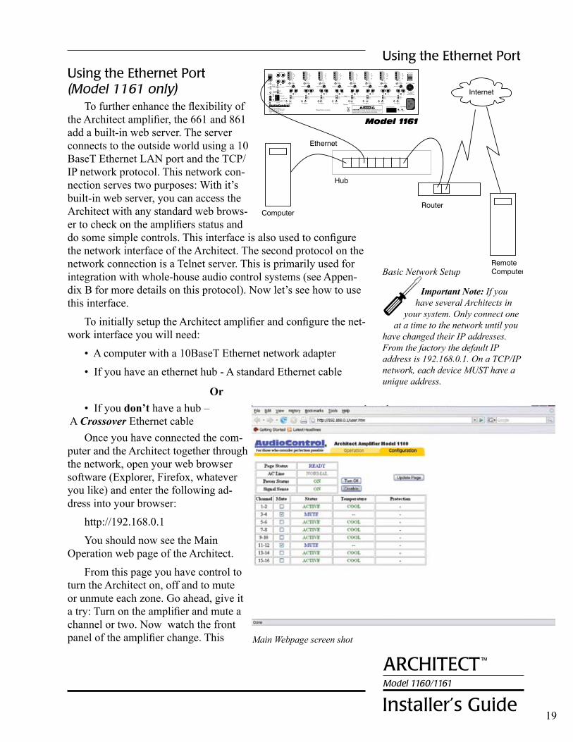
LightDrive ProTECTIoN SySTEm
This amplifier is not only smart enough to protect itself, the Architect Model 1100 Series amplifiers also protects the speakers. When the volume is turned up too high and an amplifier is pushed into clipping; the resulting distortion will probably damage the tweeters in your speakers. AudioControl’s exclusive LightDrive protection system eliminates the possibility of signal clipping in the Architect, even under the most demanding of conditions.
What is clipping? That’s where the speaker output of an amplifier tries to exceed the available voltage of the amplifier’s power supply. When that occurs, the amplifier can no longer properly create the audio signal waveform and the audio output becomes sharply squared off. This abrupt cutoff creates ultrason-ics and high frequency distortion that is too much for a poor little speaker like a tweeter to handle. LightDrive solves this problem by continuously monitoring the output of the amplifier channels. If a channel begins to get near the limit of the power supply, it immediately begins compressing the audio to reduce the volume level. This happens so quickly that you’ll never even hear the LightDrive system kick in…although your speaker will breathe a sigh of relief because it did.
What’s Inside
18
Typical Amplifier
Class H Amplifier
ArchitectModel 1160/1161
installer’s Guide
™
Using the Ethernet Port
19
Main Webpage screen shot
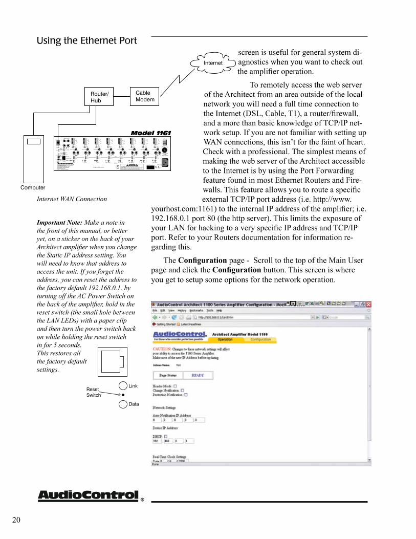
Basic Network Setup
Important Note: If you have several Architects in
your system. Only connect one at a time to the network until you
have changed their IP addresses. From the factory the default IP address is 192.168.0.1. On a TCP/IP network, each device MUST have a unique address.
Using the ethernet Port (Model 1161 only)
To further enhance the flexibility of the Architect amplifier, the 661 and 861 add a built-in web server. The server connects to the outside world using a 10 BaseT Ethernet LAN port and the TCP/IP network protocol. This network con-nection serves two purposes: With it’s built-in web server, you can access the Architect with any standard web brows-er to check on the amplifiers status and do some simple controls. This interface is also used to configure the network interface of the Architect. The second protocol on the network connection is a Telnet server. This is primarily used for integration with whole-house audio control systems (see Appen-dix B for more details on this protocol). Now let’s see how to use this interface.
To initially setup the Architect amplifier and configure the net-work interface you will need:
• A computer with a 10BaseT Ethernet network adapter
• If you have an ethernet hub - A standard Ethernet cable
Or• If you don’t have a hub –
A Crossover Ethernet cableOnce you have connected the com-
puter and the Architect together through the network, open your web browser software (Explorer, Firefox, whatever you like) and enter the following ad-dress into your browser:
http://192.168.0.1
You should now see the Main Operation web page of the Architect.
From this page you have control to turn the Architect on, off and to mute or unmute each zone. Go ahead, give it a try: Turn on the amplifier and mute a channel or two. Now watch the front panel of the amplifier change. This
®
screen is useful for general system di-agnostics when you want to check out the amplifier operation.
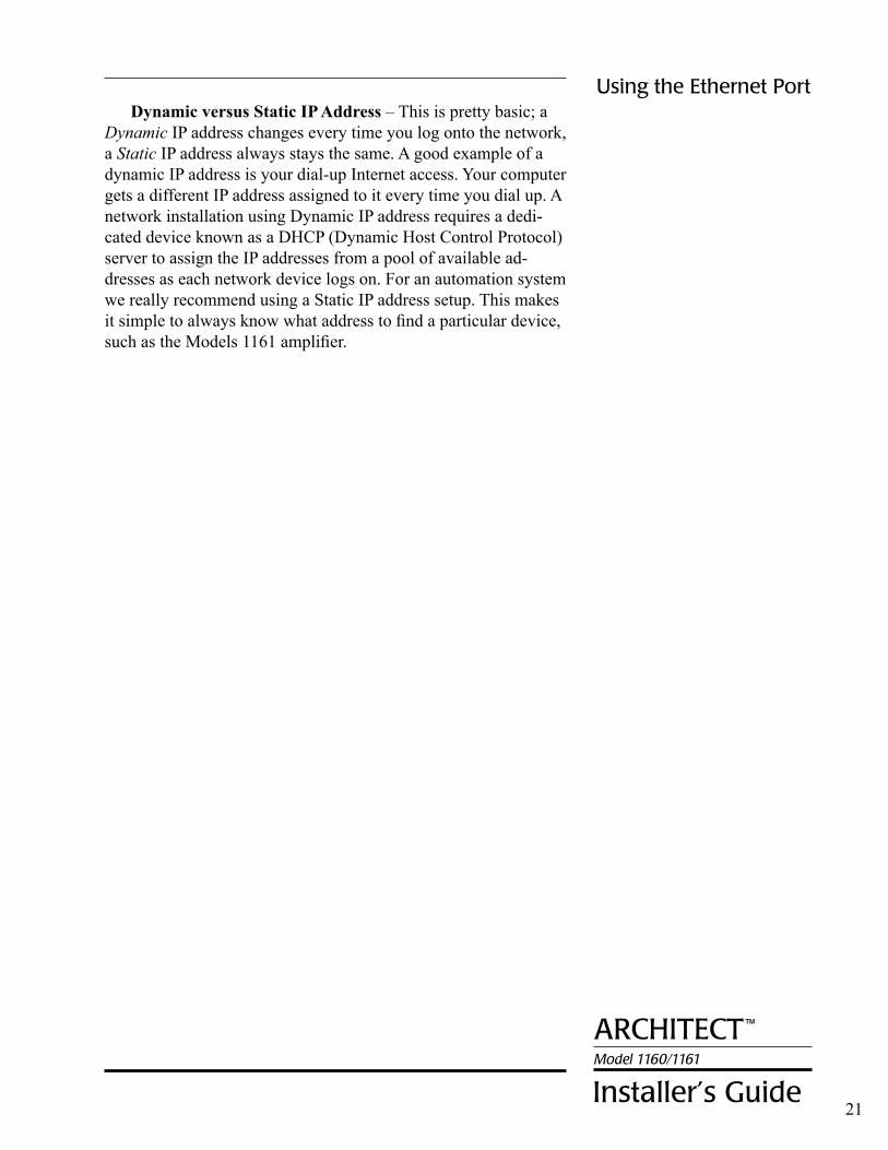
To remotely access the web server of the Architect from an area outside of the local network you will need a full time connection to the Internet (DSL, Cable, T1), a router/firewall, and a more than basic knowledge of TCP/IP net-work setup. If you are not familiar with setting up WAN connections, this isn’t for the faint of heart. Check with a professional. The simplest means of making the web server of the Architect accessible to the Internet is by using the Port Forwarding feature found in most Ethernet Routers and Fire-walls. This feature allows you to route a specific external TCP/IP port address (i.e. http://www.
yourhost.com:1161) to the internal IP address of the amplifier; i.e. 192.168.0.1 port 80 (the http server). This limits the exposure of your LAN for hacking to a very specific IP address and TCP/IP port. Refer to your Routers documentation for information re-garding this.
The Configuration page - Scroll to the top of the Main User page and click the Configuration button. This screen is where you get to setup some options for the network operation.
Using the Ethernet Port
20
Internet WAN Connection
Important Note: Make a note in the front of this manual, or better yet, on a sticker on the back of your Architect amplifier when you change the Static IP address setting. You will need to know that address to access the unit. If you forget the address, you can reset the address to the factory default 192.168.0.1. by turning off the AC Power Switch on the back of the amplifier, hold in the reset switch (the small hole between the LAN LEDs) with a paper clip and then turn the power switch back on while holding the reset switch in for 5 seconds. This restores all the factory default settings.
ArchitectModel 1160/1161
installer’s Guide
™
Dynamic versus Static IP Address – This is pretty basic; a Dynamic IP address changes every time you log onto the network, a Static IP address always stays the same. A good example of a dynamic IP address is your dial-up Internet access. Your computer gets a different IP address assigned to it every time you dial up. A network installation using Dynamic IP address requires a dedi-cated device known as a DHCP (Dynamic Host Control Protocol) server to assign the IP addresses from a pool of available ad-dresses as each network device logs on. For an automation system we really recommend using a Static IP address setup. This makes it simple to always know what address to find a particular device, such as the Models 1161 amplifier.
21
Using the Ethernet Port
®
FUSE
Troubleshooting the ArchitectAlmost all problems can be eliminated by re-checking the
wiring and settings of the Architect amplifier. If a problem cannot be solved using the guide below, please call the AudioControl fac-tory for further assistance.
1. No Sound:
a. Verify the Power LED is Blue.
b. Verify Protection LED is Blue.
c. Verify Channel Status LED is Blue.
d. Verify Source unit is operating.
e. Check the Speaker Connector plug on the rear panel
f. Check the AC Power Fuse on the rear panel.
2. Protection LED is Blue, but none of the Channel 2. Status LEDs are on:
a. Defeat the Signal-Sense circuit using the switch on the rear panel. All of the Channel Status LEDs should turn on. If they do not, call the AudioControl factory.
b. Verify Source unit is operating.
c. Adjust the preamp volume higher.
d. Adjust the Input Sensitivity control clockwise.
3. Channel Status LED is Red:
a. Check speaker leads for short. Swap speaker connec- tors on rear to see if the problem moves with the wires.
b. If the Architect is excessively hot (you cannot hold your hand on the top), turn down the volume and allow it to cool off. The Status LED should turn back to Blue after a short while. Verify that the ventila- tion holes on the rear and sides have not become blocked.
c. The speaker impedance may be too low. Use an ohmeter to measure the impedance on the speaker wires.
Troubleshooting
22
Install Tip - There are no internal fuses in the Architect
Series amplifiers. All protection
circuits are self-resetting.
ArchitectModel 1160/1161
installer’s Guide
™
4. Speaker channels are cutting in and out:
a. If using volume controls, check that they can handle the power output.
b. If bridging, the amplifier “sees” one-half the stated speaker impedance rating. Make sure the impedance is high enough. (See page 25.)
c. There maybe a short in the wires. Suspect a short if the problem happens only at the highest volumes.
5. Protection LED is Red:
a. Check main AC fuses.
b. Something rather serious has happened inside the Architect. Call the AudioControl factory.
6. Speaker Buzzing or Cracking at high volume:
• Reduce the equalizer boost at 75Hz.
7. There is no audio input signal, but the Channel Status LED is still Blue:
a. Check the Signal-Sense defeat switch on the rear panel. If it is pressed in, the Channel Status LEDs will stay on as long as the Remote Power Control is enabled.
b. The Channel Status LEDs stays on for 30-60 seconds (depending on music volume) after the audio signal has stopped to prevent prematurely turning off during quiet passages or disk changes.
8. The unit is on but you cannot trigger it off (Model 1161)
• With the ethernet control (Model 1161), the unit will stay on if either the 12v trigger is on (or jumpered) or the ethernet control is set to on.
Troubleshooting
23
®
A Brazen Plug For Other AudioControl Products
AudioControl started out making graphic equalizers in 1977. Our heritage and design experience grew from a background in professional audio, so we were never quite satisfied with what was available for the consumer audio market. Since that time, we have continued to expand our product offerings to become a key part of great home audio systems. We supply the audio compo-nents that can make a more substantial improvement in the sound of your system than almost any other addition or upgrade. More bass, better sound, less harshness and the ability to hear music the way you want it.
We make our equalizers easy to use by incorporating features such as pairing channel controls together. We help you make the system sound as good as possible with high quality subsonic filters and, in selected models, built-in test analyzers that let you make accurate adjustments to instantly compensate for main sys-tem speaker and room deficiencies. In fact, AudioControl was the world’s first manufacturer of a SEVEN CHANNEL equalizer for home theater surround sound use.
AudioControl also provides a full compliment of components for your home theater needs. The Maestro 7.1 is a THX Ultra 2 certified home theater surround processor with exceptional audio and video performance. The Diva 24 bit digital room correction system provides 8 channels of acoustical control to get the most
out of your home theater. The Savoy, Pantages and Avalon power amplifiers round out this the-ater system. Their audiophile sound quality, cool running Class H design and exclusive LightDrive protection systems say these amplifiers mean se-rious business. Together the AudioControl home theater system provides ultimate performance for your ultimate home theater.
Okay, enough commercials.
Once again, we thank you for choosing AudioControl components in your system and hope you enjoy a lifetime of performance and reliability.
24
Brazen Plug
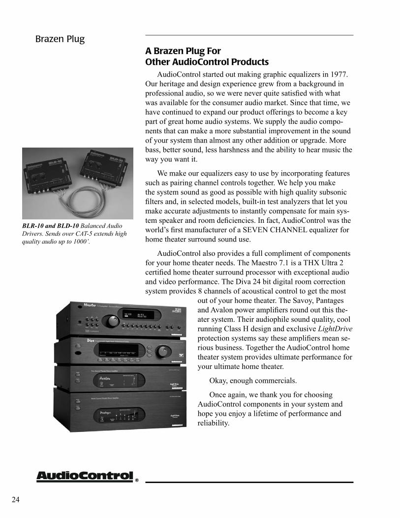
BLR-10 and BLD-10 Balanced Audio Drivers. Sends over CAT-5 extends high quality audio up to 1000’.
ArchitectModel 1160/1161
installer’s Guide
™
Appendix A Bridging The ArChiTeCT
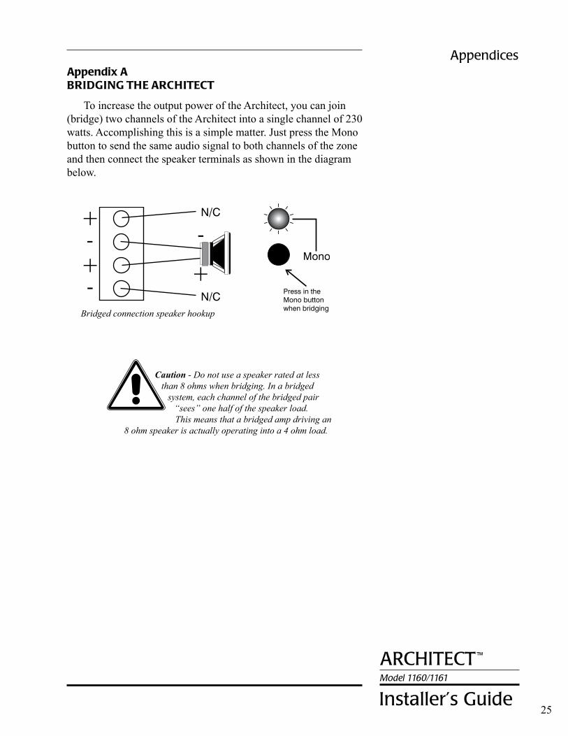
To increase the output power of the Architect, you can join (bridge) two channels of the Architect into a single channel of 230 watts. Accomplishing this is a simple matter. Just press the Mono button to send the same audio signal to both channels of the zone and then connect the speaker terminals as shown in the diagram below.
25
Appendices
Caution - Do not use a speaker rated at less than 8 ohms when bridging. In a bridged
system, each channel of the bridged pair “sees” one half of the speaker load. This means that a bridged amp driving an
8 ohm speaker is actually operating into a 4 ohm load.
Bridged connection speaker hookup
®
Appendix B Using wiTh eTherneT-BAsed AUTOmATiOn sysTems
The Ethernet LAN connection on the Model 1161 enables remote control of the amplifiers power and channel muting. While the internal web server of the Model 1161 provides an HTML web page based interface, this is not the best means of control-ling the unit from another computer system. The Architect Model 1161 utilizes a Telnet TCP/IP protocol for system programmers. The Telnet protocol uses simple ASCII text commands to control and monitor the Architect Model 1161 amplifier.
To log into the Architect Model 1161 via Telnet, you need a Telnet client program in your system. If you are using Windows, you have both Hyperterminal and Telnet. The factory default static IP address of the Model 1161 is 192.168.0.1 and telnet is active on port 23. The default user login ID and password are:
User ID: architect (note: all lower case) Password: 1100
An example of a typical telnet login session is:
/Telnet> login /Telnet> UserID?: architect /Telnet> Password?: 1100 /Telnet> User authenticated! /Telnet>
The serial ASCII control protocol over telnet allows simple integration with other automation computer systems. The basic command format is:
command<cr> <lf>
Where command is the ASCII text string of the command and <cr> is an ASCII carriage return and <lf> is a line feed. These commands are case sensitive and have a one second timeout if no valid command or delimiter is sent.
Appendices
26
ArchitectModel 1160/1161
installer’s Guide
™
P0 (zero not ‘O’) Main Power Off
P1 Main Power On
M1 Mute channel 1-2
M2 Mute channel 3-4
M3 Mute channel 5-6
M4 Mute channel 7-8
M5 Mute channel 9-10
M6 Mute channel 11-12
M7 Mute channel 13-14
M8 Mute channel 15-16
MA Mute all channels
U1 Unmute channel 1-2
U2 Unmute channel 3-4
U3 Unmute channel 5-6
U4 Unmute channel 7-8
U5 Unmute channel 9-10
U6 Unmute channel 11-12
U7 Unmute channel 13-14
U8 Unmute channel 15-16
UA Unmute all channels
B0 Defeats signal sense
B1 Signal sense Active
H0 No header and footer to inquiries
H1 Included header and footer
SIP Set IP address for notification messages. Address followed by colon and port number
AP0 Automatic protect notification off
AP1 Automatic protect notification on
AC0 Automatic change notification off
AC1 Automatic change notification on
CL Clear all logs
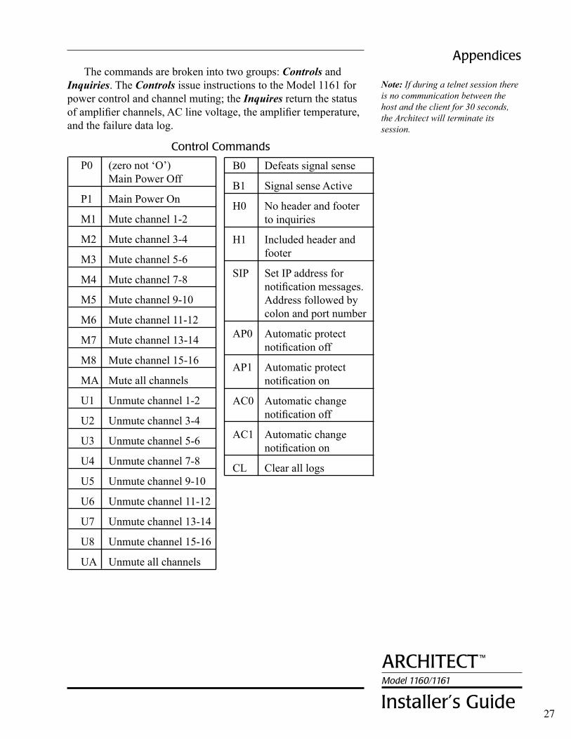
control commands
Appendices
27
The commands are broken into two groups: Controls and Inquiries. The Controls issue instructions to the Model 1161 for power control and channel muting; the Inquires return the status of amplifier channels, AC line voltage, the amplifier temperature, and the failure data log.
Note: If during a telnet session there is no communication between the host and the client for 30 seconds, the Architect will terminate its session.
®
D? Model ID three digit number
B? Signal sense 0=Defeated, 1=Active
H? Header/Footer Status 0=None, 1=Include See next page for header formats
IP? IP address and port set for notifications. Active telnet session not required for notifications.
AP? Automatic protect notification 0=off, 1=on
AC? Automatic change notification 0=off, 1=on
PB? Physical bypass 1= bypass switch engaged 0=not engaged
M? Binary string showing all zones mute status
0 = Mute 1 = Active (unmuted) (i.e. ‘001000’ – zone 3 is unmuted)
S? Protection status (zone 1-8 and Amp) 1=Normal/Active 0=Mute/Standby 2=Protect 3=Short circuit
T? Temperature (zone 1-8) 0=Cool, 1=Normal 2=Warm 3=Thermal protection 4=Channel muted
P? Main power status – 0=off, 1=on
V? AC Line voltage – 0 = Low (less than 105 VAC) 1 = Normal 2 = High (more than 125 VAC)
L? Protection data log (comma delimited text) See next page for log formats
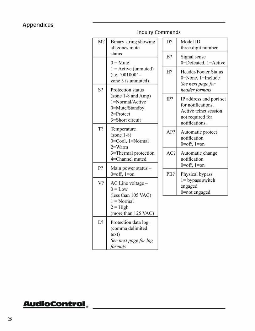
inquiry commands
28
Appendices
ArchitectModel 1160/1161
installer’s Guide
™
header Format
The response to inquiry commands may include both a header and footer for more precise identification if desired. The format of that header is as follows:
IFBXXXXXXXXAC
where I = the inquiry command, FB stands for feedback, X is the zone status, and AC is the footer identifying the response as from an AudioControl product.
For example, the response
MFB00100000AC
is the response to a zone mute inquiry (M?) and shows all zones muted (“0”) except zone 3 (“1” being active or unmuted).
Logging Format
In response to a logging inquiry (L?), the Architect will respond with the most recent twenty events. The format of the logged response is:
EECCYYYYMMDDHHMMSS
where E= event code, C=zone, Y= year, M= month, D= day, H= hour, M= minute and S=second. Event code include:
00= DC offset/global protection
01= short circuit
02= over temperate
For the zone code:
00 channel pair 1-2
01 channel pair 3-4
02 channel pair 5-6
03 channel pair 7-8
04 channel pair 9-10
05 channel pair 11-12
06 channel pair 13-14
07 channel pair 15-16
99 all zones, i.e. global protection
Appendices
29
®
30
The warrantyPeople are scared of warranties. Lots of fine print. Months
of waiting around. Well, fear no more. This warranty is designed to make you rave about AudioControl. It’s a warranty that looks out for you and your client, plus helps you resist the temptation to have your friend, who’s “good with electronics”, try to repair your AudioControl product. So go ahead, read this warranty, then send in the warranty card and comments.
“Conditional” doesn’t mean anything ominous. The Federal Trade Commission tells all manufacturers to use the term to in-dicate that certain conditions have to be met before they’ll honor the warranty. If you meet all of these conditions, we will warrant all materials and workmanship on The Architect™ for five (5) years from the date you bought it, and we will fix or replace it, at our option, during that time.
Here are the conditional conditions:1. You have to fill out the warranty card and send it to us within
15 days after installing the The Architect™.2. You must keep your sales receipt for proof of purchase show-
ing when and from whom the unit was purchased. We’re not the only ones who require this, so it’s a good habit to get into with any major purchase.
3. The Architect™ must have originally been purchased from an authorized AudioControl dealer. You do not have to be the original owner, but you do need a copy of the original sales slip.
4. You cannot let anybody who isn’t: (A) the AudioControl fac-tory; or (B) somebody authorized in writing by AudioControl to service the The Architect™. If anyone other than (A), or (B) messes with The Architect™, that voids your warranty.
5. The warranty is also void if the serial number is altered or removed, or if The Architect™ has been used improperly. Now that sounds like a big loophole, but here is all we mean by it:Unwarranted abuse is: (A) physical damage (don’t use The
Architecttm to level your projection TV); (B) improper connec-tions (120 volts into the RCA jacks can fry the poor thing); (C) sadistic things. This is the best product we know how to build, but if you strap it to the front bumper of your Range Rover, some-thing might break.
Assuming you conform to 1 through 5, and it really isn’t all that hard to do, we get the option of fixing your old unit or replacing it with a new one.
Warranty
Legalese sectionThis is the only warranty given
by AudioControl. This warranty gives you specific legal rights, and you may also have rights that vary from state to state. Prom-ises of how well The Architect™ will work are not implied by this warranty. Other than what we’ve said we’ll do in this warranty, we have no obligation, express or implied. We make no warranty of merchantability or fitness for any particular purpose. Also neither we nor anyone else who has been involved in the development or manufacture of the unit will have any liability of any incidental, consequential, special or punitive damages, including but not lim-ited to any lost profits or damage to other parts of your system by hooking up to the unit (whether the claim is one for breach of warranty, negligence of other tort, or any other kind of claim). Some states do not allow limitations of consequential damages.
Failure to send in a properly completed warranty card negates any service claims.
The warranty included with the unit shall supersede this plain-text version if there is any inconsis-tency between the two.

ArchitectModel 1160/1161
installer’s Guide
™
31
What to do if you need servicewhat to do if you need service
First, contact AudioControl, either by e-mail, phone or FAX. We’ll verify if there is anything wrong that you can fix yourself, or that it needs to be sent back to our factory for repair. Please include the following items with the returning unit:1) A copy of your proof of purchase (that sales receipt we’ve
been harping about). No originals please. We cannot guarantee returning them to you.
2) A brief explanation of the trouble you are having with The Architecttm
. (You’d be surprised how many people forget this.)
3) A return street address. (No PO Boxes, please)
4) A daytime phone number in case our technician has a question about the problem you are having.
You’re responsible for the freight charges to us, but we’ll pay the return freight back as long as the unit is under warranty. We match whatever shipping method you use to send it to us, so if you return the unit overnight freight, we send it back overnight. We recommend United Parcel Service (UPS) for most shipments.
Repair service is available at:
®
Attn: Service Department 22410 70th Avenue West Mountlake Terrace, WA 98043 USA Phone 425/775-8461 • FAX 425/778-3166 email: [email protected]
®
Block Diagram
32
ArchitectModel 1160/1161
installer’s Guide
™
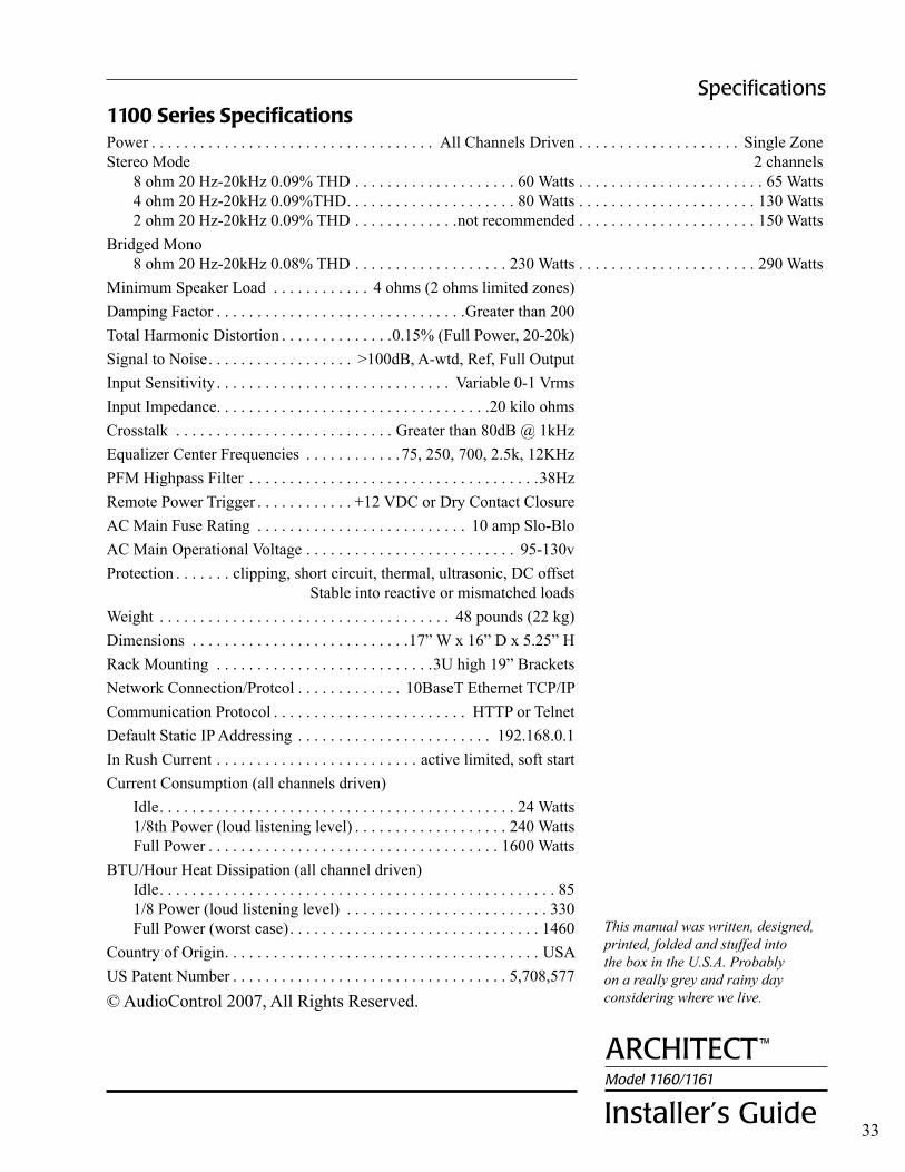
1100 series specificationsPower . . . . . . . . . . . . . . . . . . . . . . . . . . . . . . . . . . . All Channels Driven . . . . . . . . . . . . . . . . . . . . Single Zone Stereo Mode . . . . . . . . . . . . . . . . . . . . . . . . . . . . . . . . . . . . . . . . . . . . . . . . . . . . . . . . . . . . . . . . . . . . .2 channels 8 ohm 20 Hz-20kHz 0.09% THD . . . . . . . . . . . . . . . . . . . . 60 Watts . . . . . . . . . . . . . . . . . . . . . . . 65 Watts 4 ohm 20 Hz-20kHz 0.09%THD. . . . . . . . . . . . . . . . . . . . . 80 Watts . . . . . . . . . . . . . . . . . . . . . . 130 Watts 2 ohm 20 Hz-20kHz 0.09% THD . . . . . . . . . . . . .not recommended . . . . . . . . . . . . . . . . . . . . . . 150 WattsBridged Mono 8 ohm 20 Hz-20kHz 0.08% THD . . . . . . . . . . . . . . . . . . . 230 Watts . . . . . . . . . . . . . . . . . . . . . . 290 WattsMinimum Speaker Load . . . . . . . . . . . . 4 ohms (2 ohms limited zones)Damping Factor . . . . . . . . . . . . . . . . . . . . . . . . . . . . . . .Greater than 200Total Harmonic Distortion . . . . . . . . . . . . . .0.15% (Full Power, 20-20k)Signal to Noise . . . . . . . . . . . . . . . . . . >100dB, A-wtd, Ref, Full OutputInput Sensitivity . . . . . . . . . . . . . . . . . . . . . . . . . . . . . Variable 0-1 VrmsInput Impedance. . . . . . . . . . . . . . . . . . . . . . . . . . . . . . . . . .20 kilo ohmsCrosstalk . . . . . . . . . . . . . . . . . . . . . . . . . . . Greater than 80dB @ 1kHzEqualizer Center Frequencies . . . . . . . . . . . .75, 250, 700, 2.5k, 12KHzPFM Highpass Filter . . . . . . . . . . . . . . . . . . . . . . . . . . . . . . . . . . . .38Hz Remote Power Trigger . . . . . . . . . . . . +12 VDC or Dry Contact ClosureAC Main Fuse Rating . . . . . . . . . . . . . . . . . . . . . . . . . . 10 amp Slo-BloAC Main Operational Voltage . . . . . . . . . . . . . . . . . . . . . . . . . . 95-130vProtection . . . . . . . clipping, short circuit, thermal, ultrasonic, DC offset . . . . . . . . . . . . . . . . . . . . . .Stable into reactive or mismatched loadsWeight . . . . . . . . . . . . . . . . . . . . . . . . . . . . . . . . . . . . 48 pounds (22 kg)Dimensions . . . . . . . . . . . . . . . . . . . . . . . . . . .17” W x 16” D x 5.25” HRack Mounting . . . . . . . . . . . . . . . . . . . . . . . . . . .3U high 19” BracketsNetwork Connection/Protcol . . . . . . . . . . . . . 10BaseT Ethernet TCP/IPCommunication Protocol . . . . . . . . . . . . . . . . . . . . . . . . HTTP or TelnetDefault Static IP Addressing . . . . . . . . . . . . . . . . . . . . . . . . 192.168.0.1In Rush Current . . . . . . . . . . . . . . . . . . . . . . . . . active limited, soft startCurrent Consumption (all channels driven) Idle. . . . . . . . . . . . . . . . . . . . . . . . . . . . . . . . . . . . . . . . . . . . 24 Watts 1/8th Power (loud listening level) . . . . . . . . . . . . . . . . . . . 240 Watts Full Power . . . . . . . . . . . . . . . . . . . . . . . . . . . . . . . . . . . . 1600 WattsBTU/Hour Heat Dissipation (all channel driven) Idle. . . . . . . . . . . . . . . . . . . . . . . . . . . . . . . . . . . . . . . . . . . . . . . . . 85 1/8 Power (loud listening level) . . . . . . . . . . . . . . . . . . . . . . . . . 330 Full Power (worst case) . . . . . . . . . . . . . . . . . . . . . . . . . . . . . . . 1460Country of Origin. . . . . . . . . . . . . . . . . . . . . . . . . . . . . . . . . . . . . . . USAUS Patent Number . . . . . . . . . . . . . . . . . . . . . . . . . . . . . . . . . . 5,708,577© AudioControl 2007, All Rights Reserved.
Specifications
33
This manual was written, designed, printed, folded and stuffed into the box in the U.S.A. Probably on a really grey and rainy day considering where we live.

P/N 913 095
22410 70th Avenue West Mountlake Terrace, WA 98043 USA 425-775-8461 • Fax 425-778-3166 e-mail: [email protected]
Visit us on the web at www.audiocontrol.com
®For Those Who Consider Perfection Possible®