archicad ifc 2x3
TRANSCRIPT
IFC 2x3 Reference Guide for ArchiCAD 13
GRAPHISOFTVisit the GRAPHISOFT website at http://www.graphisoft.com for local distributor and product availability information.
IFC 2x3 Reference Guide for ArchiCAD 13Copyright © 2009 by GRAPHISOFT, all rights reserved. Reproduction, paraphrasing or translation without express prior written
permission is strictly prohibited.Trademarks
ArchiCAD and GRAPHISOFT MEP Modeler are registered trademarks, Virtual Building and GDL are trademarks of GRAPHISOFT. IFC and IAI are trademarks of the International Alliance for Interoperability.
All other trademarks are the property of their respective holders.
CONTENTSIntroduction . . . . . . . . . . . . . . . . . . . . . . . . . . . . . . . . . . . . . . . . . . . . . . . 5Installation of IFC 2x3 in ArchiCAD 13 . . . . . . . . . . . . . . . . . . . . . . . . 5Helpful Hints in Planning an IFC Project . . . . . . . . . . . . . . . . . . . . . . . 6IFC Interface in ArchiCAD. . . . . . . . . . . . . . . . . . . . . . . . . . . . . . . . . . . 6Basic IFC Terms and Definitions . . . . . . . . . . . . . . . . . . . . . . . . . . . . . . 8
Create New Property . . . . . . . . . . . . . . . . . . . . . . . . . . . . . . . . . . . . . . . 9Save and Apply IFC Parameters in ArchiCAD. . . . . . . . . . . . . . . . . . 10IFC Export/Import Settings . . . . . . . . . . . . . . . . . . . . . . . . . . . . . . . . . 11
Units Options . . . . . . . . . . . . . . . . . . . . . . . . . . . . . . . . . . . . . . . . . . . . 11Export Options . . . . . . . . . . . . . . . . . . . . . . . . . . . . . . . . . . . . . . . . . . . 11Custom Property Set Options . . . . . . . . . . . . . . . . . . . . . . . . . . . . . . . . 14Exterior Options . . . . . . . . . . . . . . . . . . . . . . . . . . . . . . . . . . . . . . . . . . 16Person and Organization Options . . . . . . . . . . . . . . . . . . . . . . . . . . . . 17Miscellaneous Options . . . . . . . . . . . . . . . . . . . . . . . . . . . . . . . . . . . . . 17
Merge IFC to ArchiCAD . . . . . . . . . . . . . . . . . . . . . . . . . . . . . . . . . . . . 19Merge to IFC Model. . . . . . . . . . . . . . . . . . . . . . . . . . . . . . . . . . . . . . . . 20IFC Manager. . . . . . . . . . . . . . . . . . . . . . . . . . . . . . . . . . . . . . . . . . . . . . 21Structural-Related IFC Features . . . . . . . . . . . . . . . . . . . . . . . . . . . . . 22
Layer Settings and Partial Structure Display. . . . . . . . . . . . . . . . . . . . 22Load-Bearing Property. . . . . . . . . . . . . . . . . . . . . . . . . . . . . . . . . . . . . 24Standard Steel and Custom Profiles . . . . . . . . . . . . . . . . . . . . . . . . . . . 25Materials. . . . . . . . . . . . . . . . . . . . . . . . . . . . . . . . . . . . . . . . . . . . . . . . 26
IFC Settings for Thermal Calculation . . . . . . . . . . . . . . . . . . . . . . . . . 28IFC Settings for Quantity Takeoff . . . . . . . . . . . . . . . . . . . . . . . . . . . . 30
IFC 2x3 Reference Guide for ArchiCAD 13 3
Contents
4 IFC 2x3 Reference Guide for ArchiCAD 13
ArchiCAD IFC 2x3 Guide
ARCHICAD IFC 2X3 GUIDE
IntroductionIFC – Industry Foundation Classes – is a neutral file format that makes it possible to exchange information between different CAD systems and other systems in the building and facility management sectors. The IFC format is ISO-certified and can be integrated into any existing quality assurance polices your office may have. IFC is developed in part by the IAI – the International Alliance for Interoperability. Today there are over 600 members with 13 chapters around the world. For more information, see: http://www.buildingsmart.com/.GRAPHISOFT has played an active role within the IAI organization and supports the latest IFC standard, IFC 2x3. The IFC standard enables ArchiCAD to communicate with other disciplines within the context of the building model, and to coordinate a building project entirely in 3D. The building model can also be exported back to literally hundreds of other systems that support IFC.BIM, or “Building Information Modeling,” is one of the biggest advances in the building industry’s working methods since the introduction of CAD software. The gap between CAD software and hardware has closed dramatically the last few years, making it economically viable to coordinate projects in 3D. BIM is NOT synonymous with 3D projects. Three-dimensional geometric representation is only one part of the digital deliverables. A project includes non-graphical information, such as calculations that are used in surveying, facility management and energy calculation.But the first and perhaps most important step toward a full BIM working method is to model and coordinate in 3D. Architects, engineers, HVAC contractors and clients all gain from using a BIM model. A BIM model can gradually encompass information used by facility managers, accountants, and environmental regulators.
Even in a later stage of the model's life cycle, BIM is useful for real estate agents, security companies, fire brigades and cleaning contractors.A prerequisite for a successful BIM project is that intelligent information can be exchanged between different software and even operating systems, throughout the stages of the building process. This interoperability demands a neutral file format with an open standard that supports different systems. IFC is such a system, enabling us to synchronize building models between the disciplines much more easily. With its user-friendly interface and high degree of customizability, the IFC add-on for ArchiCAD enables users to communicate in an efficient way, to focus on the needed elements and to locate any errors in design development.This Guide has been created to provide ArchiCAD users an insight into the IFC standard and how it works in ArchiCAD. The IFC version discussed in this Guide is 2x3 for GRAPHISOFT's ArchiCAD 13.
Installation of IFC 2x3 in ArchiCAD 13The IFC 2x3 add-on automatically installed with ArchiCAD 13 is located in the Add-Ons/Import-Export folder in the ArchiCAD program folder. For the latest beta and final releases of the IFC add-on, see GRAPHISOFT’s web site: http://www.graphisoft.com/ifc/Please note that IFC 2x3 is the default and the supported add-on for ArchiCAD 13.
IFC 2x3 Reference Guide for ArchiCAD 13 5
ArchiCAD IFC 2x3 Guide
Helpful Hints in Planning an IFC Project1) First, decide which IFC version (e.g. 2x3 versus 2x2) should
be used. Ensure that your partners, who will be using the IFC file, have compatible programs enabling them to read your file version.
2) Next, consider what type of information should be exported to the different disciplines. Different disciplines will require different parts of the total informational flow of an IFC-project. For example, structural engineers will want the load-bearing parts of the building (see Structural-Related IFC Features later in this document), while an HVAC consultant will need a richer model with more internal information. Once these issues are decided, the IFC 2X3 Add-On’s interface enables you to filter the building information model accordingly before exporting it.
3) It is good practice, in a newly started project, to start with a simple model for export, to verify that all of the required information is exported and imported correctly into and from each discipline’s respective program. Once this simple model has been exported and read correctly, then more information can be added to the model successively.
4) When exporting an IFC model, it is good practice to check the IFC model in an IFC viewer. There are many free IFC viewers on the market that can be readily downloaded:Solibri Model Viewer: http://www.solibri.comDDS-CAD Viewer: http://www.dds-cad.netNemetschek IFC Viewer: http://www.nemetschek.co.uk/ifcAdditional information can be found at the following Wiki address: http://www.ifcwiki.org/index.php/Free_Software
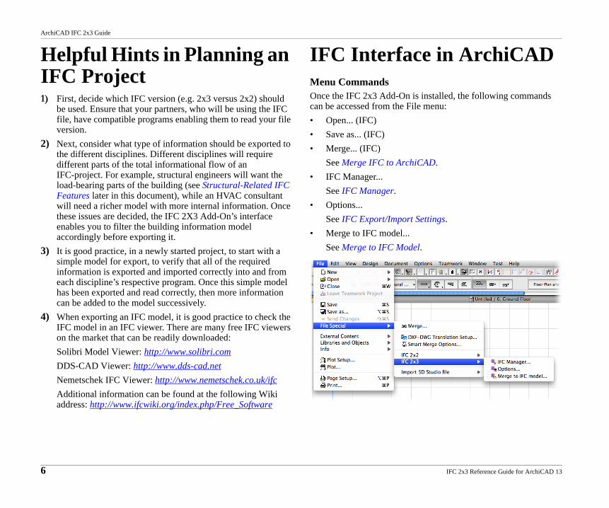
IFC Interface in ArchiCADMenu CommandsOnce the IFC 2x3 Add-On is installed, the following commands can be accessed from the File menu:• Open... (IFC)• Save as... (IFC)• Merge... (IFC)
See Merge IFC to ArchiCAD.• IFC Manager...
See IFC Manager.• Options...
See IFC Export/Import Settings.• Merge to IFC model...
See Merge to IFC Model.
6 IFC 2x3 Reference Guide for ArchiCAD 13
ArchiCAD IFC 2x3 Guide
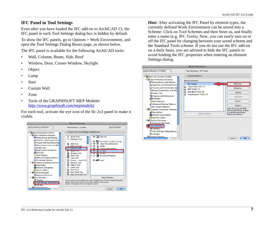
IFC Panel in Tool SettingsEven after you have loaded the IFC add-on to ArchiCAD 13, the IFC panel in each Tool Settings dialog box is hidden by default. To show the IFC panels, go to Options > Work Environment, and open the Tool Settings Dialog Boxes page, as shown below.The IFC panel is available for the following ArchiCAD tools:• Wall, Column, Beam, Slab, Roof• Window, Door, Corner-Window, Skylight• Object• Lamp• Stair• Curtain Wall• Zone• Tools of the GRAPHISOFT MEP Modeler
http://www.graphisoft.com/mepmodelerFor each tool, activate the eye icon of the Ifc 2x3 panel to make it visible.
Hint: After activating the IFC Panel by element types, the currently defined Work Environment can be stored into a Scheme. Click on Tool Schemes and then Store as, and finally enter a name (e.g. IFC Tools). Now, you can easily turn on or off the IFC panel by changing between your saved scheme and the Standard Tools scheme. If you do not use the IFC add-on on a daily basis, you are advised to hide the IFC panels to avoid loading the IFC properties when entering an element Settings dialog.
IFC 2x3 Reference Guide for ArchiCAD 13 7
ArchiCAD IFC 2x3 Guide
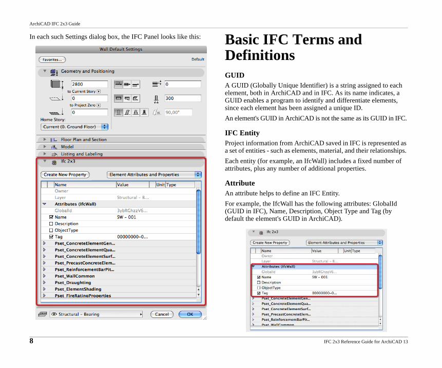
In each such Settings dialog box, the IFC Panel looks like this: Basic IFC Terms and DefinitionsGUIDA GUID (Globally Unique Identifier) is a string assigned to each element, both in ArchiCAD and in IFC. As its name indicates, a GUID enables a program to identify and differentiate elements, since each element has been assigned a unique ID.An element's GUID in ArchiCAD is not the same as its GUID in IFC.
IFC EntityProject information from ArchiCAD saved in IFC is represented as a set of entities - such as elements, material, and their relationships. Each entity (for example, an IfcWall) includes a fixed number of attributes, plus any number of additional properties.
AttributeAn attribute helps to define an IFC Entity.For example, the IfcWall has the following attributes: GlobalId (GUID in IFC), Name, Description, Object Type and Tag (by default the element's GUID in ArchiCAD).
8 IFC 2x3 Reference Guide for ArchiCAD 13
ArchiCAD IFC 2x3 Guide
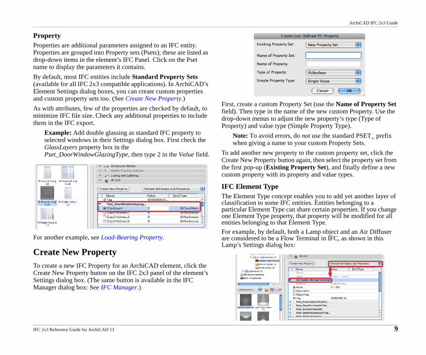
PropertyProperties are additional parameters assigned to an IFC entity. Properties are grouped into Property sets (Psets); these are listed as drop-down items in the element’s IFC Panel. Click on the Pset name to display the parameters it contains.By default, most IFC entities include Standard Property Sets (available for all IFC 2x3 compatible applications). In ArchiCAD’s Element Settings dialog boxes, you can create custom properties and custom property sets too. (See Create New Property.)As with attributes, few of the properties are checked by default, to minimize IFC file size. Check any additional properties to include them in the IFC export.
Example: Add double glassing as standard IFC property to selected windows in their Settings dialog box. First check the GlassLayers property box in the Pset_DoorWindowGlazingType, then type 2 in the Value field.
For another example, see Load-Bearing Property.
Create New PropertyTo create a new IFC Property for an ArchiCAD element, click the Create New Property button on the IFC 2x3 panel of the element’s Settings dialog box. (The same button is available in the IFC Manager dialog box: See IFC Manager.)
First, create a custom Property Set (use the Name of Property Set field). Then type in the name of the new custom Property. Use the drop-down menus to adjust the new property’s type (Type of Property) and value type (Simple Property Type).
Note: To avoid errors, do not use the standard PSET_ prefix when giving a name to your custom Property Sets.
To add another new property to the custom property set, click the Create New Property button again, then select the property set from the first pop-up (Existing Property Set), and finally define a new custom property with its property and value types.
IFC Element TypeThe Element Type concept enables you to add yet another layer of classification to some IFC entities. Entities belonging to a particular Element Type can share certain properties. If you change one Element Type property, that property will be modified for all entities belonging to that Element Type.For example, by default, both a Lamp object and an Air Diffuser are considered to be a Flow Terminal in IFC, as shown in this Lamp’s Settings dialog box:
IFC 2x3 Reference Guide for ArchiCAD 13 9
ArchiCAD IFC 2x3 Guide
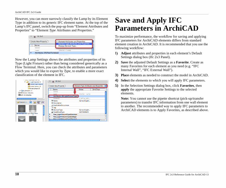
However, you can more narrowly classify the Lamp by its Element Type in addition to its generic IFC element name. At the top of the Lamp’s IFC panel, switch the pop-up from “Element Attributes and Properties” to “Element Type Attributes and Properties.”
Now the Lamp Settings shows the attributes and properties of its Type (Light Fixture) rather than being considered generically as a Flow Terminal. Here, you can check the attributes and parameters which you would like to export by Type, to enable a more exact classification of the element in IFC.
Save and Apply IFC Parameters in ArchiCADTo maximize performance, the workflow for saving and applying IFC parameters for ArchiCAD elements differs from standard element creation in ArchiCAD. It is recommended that you use the following workflow:1) Adjust attributes and properties in each element’s Default
Settings dialog box (Ifc 2x3 Panel).2) Save the adjusted Default Settings as a Favorite. Create as
many Favorites for each element as you need (e.g. “IFC Internal Wall”, “IFC External Wall”).
3) Place elements as needed to construct the model in ArchiCAD.4) Select the elements to which you will apply IFC parameters. 5) In the Selection Settings dialog box, click Favorites, then
apply the appropriate Favorite Settings to the selected elements.Note: You cannot use the pipette shortcut (pick-up/transfer parameters) to transfer IFC information from one wall element to another. The recommended way to apply IFC parameters to ArchiCAD elements is to Apply Favorites, as described above.
10 IFC 2x3 Reference Guide for ArchiCAD 13
ArchiCAD IFC 2x3 Guide
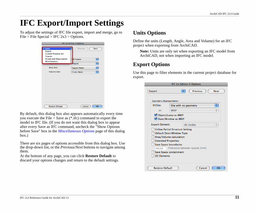
IFC Export/Import SettingsTo adjust the settings of IFC file export, import and merge, go to File > File Special > IFC 2x3 > Options.
By default, this dialog box also appears automatically every time you execute the File > Save as (*.ifc) command to export the model to IFC file. (If you do not want this dialog box to appear after every Save as IFC command, uncheck the "Show Options before Save" box in the Miscellaneous Options page of this dialog box.)
There are six pages of options accessible from this dialog box. Use the drop-down list, or the Previous/Next buttons to navigate among them.At the bottom of any page, you can click Restore Default to discard your options changes and return to the default settings.
Units OptionsDefine the units (Length, Angle, Area and Volume) for an IFC project when exporting from ArchiCAD.
Note: Units are only set when exporting an IFC model from ArchiCAD, not when importing an IFC model.
Export OptionsUse this page to filter elements in the current project database for export.
IFC 2x3 Reference Guide for ArchiCAD 13 11
ArchiCAD IFC 2x3 Guide
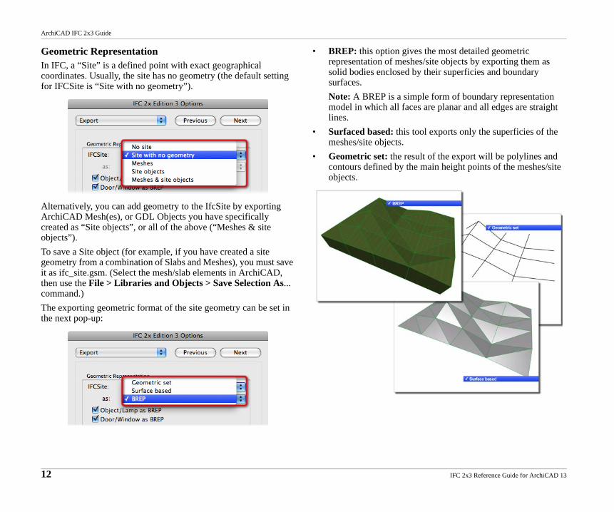
Geometric RepresentationIn IFC, a “Site” is a defined point with exact geographical coordinates. Usually, the site has no geometry (the default setting for IFCSite is “Site with no geometry”).
Alternatively, you can add geometry to the IfcSite by exporting ArchiCAD Mesh(es), or GDL Objects you have specifically created as “Site objects”, or all of the above (“Meshes & site objects”).To save a Site object (for example, if you have created a site geometry from a combination of Slabs and Meshes), you must save it as ifc_site.gsm. (Select the mesh/slab elements in ArchiCAD, then use the File > Libraries and Objects > Save Selection As... command.)The exporting geometric format of the site geometry can be set in the next pop-up:
• BREP: this option gives the most detailed geometric representation of meshes/site objects by exporting them as solid bodies enclosed by their superficies and boundary surfaces.Note: A BREP is a simple form of boundary representation model in which all faces are planar and all edges are straight lines.
• Surfaced based: this tool exports only the superficies of the meshes/site objects.
• Geometric set: the result of the export will be polylines and contours defined by the main height points of the meshes/site objects.
12 IFC 2x3 Reference Guide for ArchiCAD 13
ArchiCAD IFC 2x3 Guide
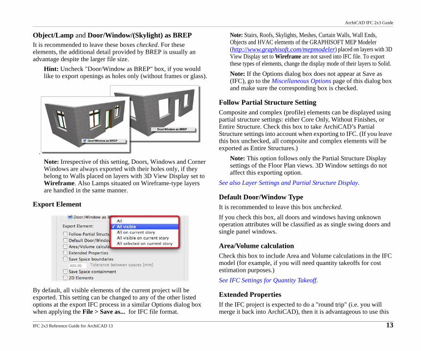
Object/Lamp and Door/Window/(Skylight) as BREPIt is recommended to leave these boxes checked. For these elements, the additional detail provided by BREP is usually an advantage despite the larger file size.
Hint: Uncheck "Door/Window as BREP" box, if you would like to export openings as holes only (without frames or glass).
.Note: Irrespective of this setting, Doors, Windows and Corner Windows are always exported with their holes only, if they belong to Walls placed on layers with 3D View Display set to Wireframe. Also Lamps situated on Wireframe-type layers are handled in the same manner.
Export Element
By default, all visible elements of the current project will be exported. This setting can be changed to any of the other listed options at the export IFC process in a similar Options dialog box when applying the File > Save as... for IFC file format.
Note: Stairs, Roofs, Skylights, Meshes, Curtain Walls, Wall Ends, Objects and HVAC elements of the GRAPHISOFT MEP Modeler (http://www.graphisoft.com/mepmodeler) placed on layers with 3D View Display set to Wireframe are not saved into IFC file. To export these types of elements, change the display mode of their layers to Solid.Note: If the Options dialog box does not appear at Save as (IFC), go to the Miscellaneous Options page of this dialog box and make sure the corresponding box is checked.
Follow Partial Structure SettingComposite and complex (profile) elements can be displayed using partial structure settings: either Core Only, Without Finishes, or Entire Structure. Check this box to take ArchiCAD’s Partial Structure settings into account when exporting to IFC. (If you leave this box unchecked, all composite and complex elements will be exported as Entire Structures.)
Note: This option follows only the Partial Structure Display settings of the Floor Plan views. 3D Window settings do not affect this exporting option.
See also Layer Settings and Partial Structure Display.
Default Door/Window TypeIt is recommended to leave this box unchecked.If you check this box, all doors and windows having unknown operation attributes will be classified as as single swing doors and single panel windows.
Area/Volume calculationCheck this box to include Area and Volume calculations in the IFC model (for example, if you will need quantity takeoffs for cost estimation purposes.)See IFC Settings for Quantity Takeoff.
Extended PropertiesIf the IFC project is expected to do a "round trip" (i.e. you will merge it back into ArchiCAD), then it is advantageous to use this
IFC 2x3 Reference Guide for ArchiCAD 13 13
ArchiCAD IFC 2x3 Guide
setting when exporting the model to IFC. This option will enable ArchiCAD to try to map the original object when you import the IFC model again.
Note: Choosing this option will significantly increase the IFC file size.
Save Space boundariesCheck this box only if you are using the IFC model in thermal calculation applications (e.g. with Energy Plus). Using this option increases processing time and file size dramatically.Space boundaries define the logical connection between Zones (IfcSpaces) and the building elements (e.g. Walls and Slabs) that enclose them.See IFC Settings for Thermal Calculation.
Save Space containment Check this box if you are using the IFC model in facility management applications.Space containment defines the relationship between IfcSpace (Zones in ArchiCAD) and Furnishing, Mechanical (HVAC) and other contained elements within the space.
2D ElementsThe IFC 2x3 add-on is able to export (and import) 2D elements like Text, Line, Arc/Circle, Polyline and Fills.
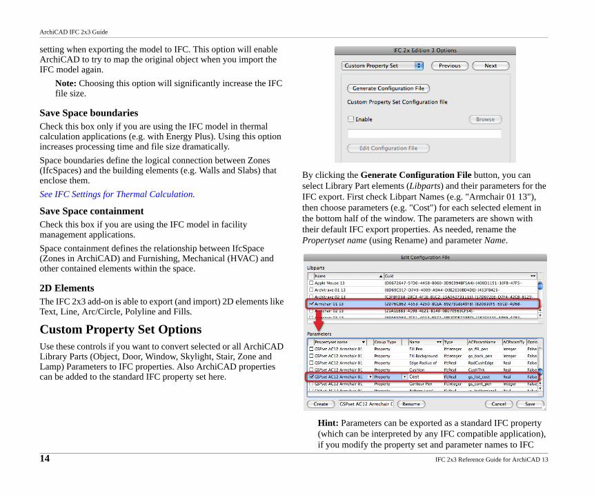
Custom Property Set OptionsUse these controls if you want to convert selected or all ArchiCAD Library Parts (Object, Door, Window, Skylight, Stair, Zone and Lamp) Parameters to IFC properties. Also ArchiCAD properties can be added to the standard IFC property set here.
By clicking the Generate Configuration File button, you can select Library Part elements (Libparts) and their parameters for the IFC export. First check Libpart Names (e.g. "Armchair 01 13"), then choose parameters (e.g. "Cost") for each selected element in the bottom half of the window. The parameters are shown with their default IFC export properties. As needed, rename the Propertyset name (using Rename) and parameter Name.
Hint: Parameters can be exported as a standard IFC property (which can be interpreted by any IFC compatible application), if you modify the property set and parameter names to IFC
14 IFC 2x3 Reference Guide for ArchiCAD 13
ArchiCAD IFC 2x3 Guide
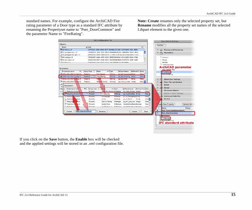
standard names. For example, configure the ArchiCAD Fire rating parameter of a Door type as a standard IFC attribute by renaming the Propertyset name to "Pset_DoorCommon" and the parameter Name to "FireRating".
Note: Create renames only the selected property set, but Rename modifies all the property set names of the selected Libpart element to the given one.
If you click on the Save button, the Enable box will be checked and the applied settings will be stored in an .xml configuration file.
IFC 2x3 Reference Guide for ArchiCAD 13 15
ArchiCAD IFC 2x3 Guide
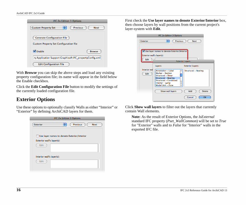
With Browse you can skip the above steps and load any existing property configuration file; its name will appear in the field below the Enable checkbox.Click the Edit Configuration File button to modify the settings of the currently loaded configuration file.
Exterior OptionsUse these options to optionally classify Walls as either “Interior” or “Exterior” by defining ArchiCAD layers for them.
First check the Use layer names to denote Exterior/Interior box, then choose layers by wall positions from the current project's layer-system with Edit.
Click Show wall layers to filter out the layers that currently contain Wall elements.
Note: As the result of Exterior Options, the IsExternal standard IFC property (Pset_WallCommon) will be set to True for "Exterior" walls and to False for "Interior" walls in the exported IFC file.
16 IFC 2x3 Reference Guide for ArchiCAD 13
ArchiCAD IFC 2x3 Guide
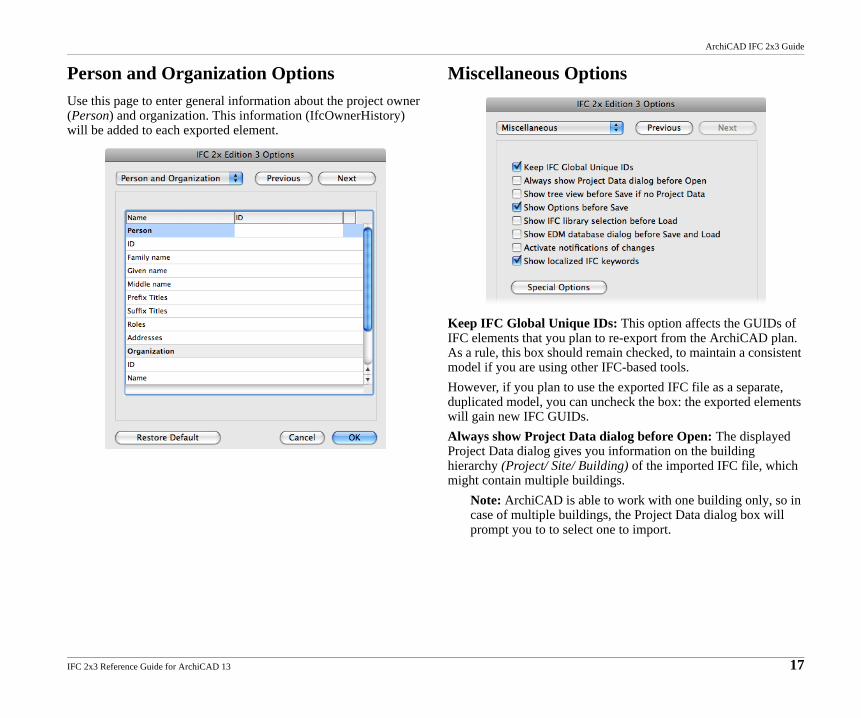
Person and Organization OptionsUse this page to enter general information about the project owner (Person) and organization. This information (IfcOwnerHistory) will be added to each exported element.
Miscellaneous Options
Keep IFC Global Unique IDs: This option affects the GUIDs of IFC elements that you plan to re-export from the ArchiCAD plan. As a rule, this box should remain checked, to maintain a consistent model if you are using other IFC-based tools. However, if you plan to use the exported IFC file as a separate, duplicated model, you can uncheck the box: the exported elements will gain new IFC GUIDs.Always show Project Data dialog before Open: The displayed Project Data dialog gives you information on the building hierarchy (Project/ Site/ Building) of the imported IFC file, which might contain multiple buildings.
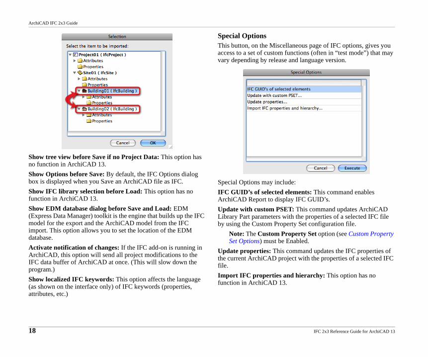
Note: ArchiCAD is able to work with one building only, so in case of multiple buildings, the Project Data dialog box will prompt you to to select one to import.
IFC 2x3 Reference Guide for ArchiCAD 13 17
ArchiCAD IFC 2x3 Guide
Show tree view before Save if no Project Data: This option has no function in ArchiCAD 13.Show Options before Save: By default, the IFC Options dialog box is displayed when you Save an ArchiCAD file as IFC.Show IFC library selection before Load: This option has no function in ArchiCAD 13.Show EDM database dialog before Save and Load: EDM (Express Data Manager) toolkit is the engine that builds up the IFC model for the export and the ArchiCAD model from the IFC import. This option allows you to set the location of the EDM database.Activate notification of changes: If the IFC add-on is running in ArchiCAD, this option will send all project modifications to the IFC data buffer of ArchiCAD at once. (This will slow down the program.) Show localized IFC keywords: This option affects the language (as shown on the interface only) of IFC keywords (properties, attributes, etc.)
Special OptionsThis button, on the Miscellaneous page of IFC options, gives you access to a set of custom functions (often in “test mode”) that may vary depending by release and language version.
Special Options may include:IFC GUID’s of selected elements: This command enables ArchiCAD Report to display IFC GUID’s.Update with custom PSET: This command updates ArchiCAD Library Part parameters with the properties of a selected IFC file by using the Custom Property Set configuration file.
Note: The Custom Property Set option (see Custom Property Set Options) must be Enabled.
Update properties: This command updates the IFC properties of the current ArchiCAD project with the properties of a selected IFC file.Import IFC properties and hierarchy: This option has no function in ArchiCAD 13.
18 IFC 2x3 Reference Guide for ArchiCAD 13
ArchiCAD IFC 2x3 Guide
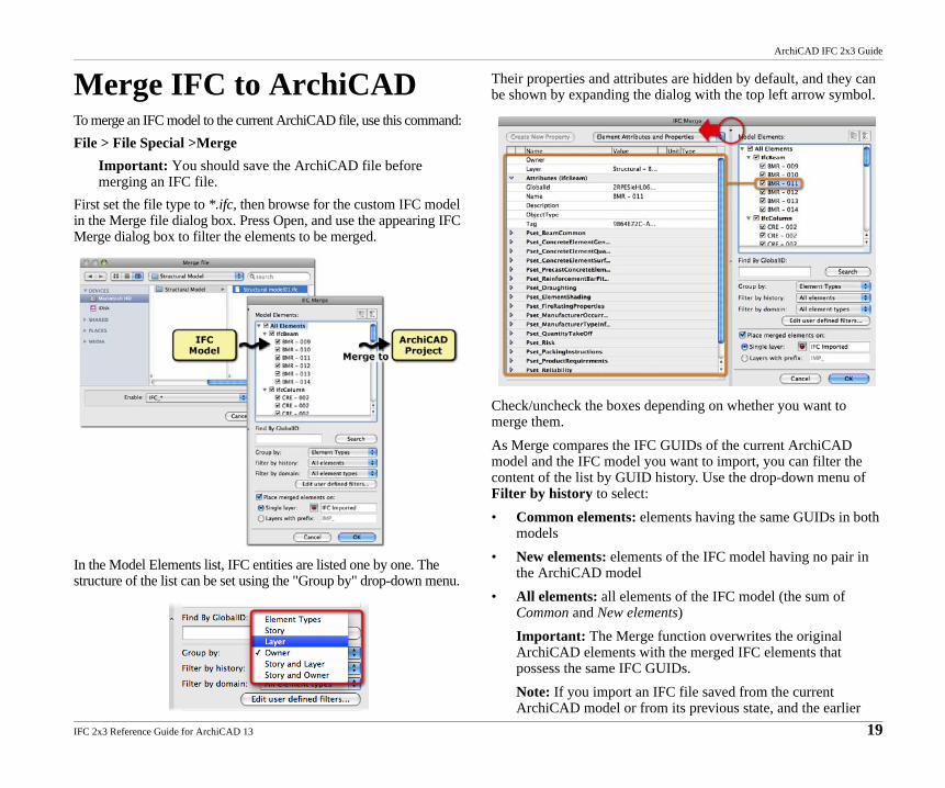
Merge IFC to ArchiCADTo merge an IFC model to the current ArchiCAD file, use this command:File > File Special >Merge
Important: You should save the ArchiCAD file before merging an IFC file.
First set the file type to *.ifc, then browse for the custom IFC model in the Merge file dialog box. Press Open, and use the appearing IFC Merge dialog box to filter the elements to be merged.
In the Model Elements list, IFC entities are listed one by one. The structure of the list can be set using the "Group by" drop-down menu.
Their properties and attributes are hidden by default, and they can be shown by expanding the dialog with the top left arrow symbol.
Check/uncheck the boxes depending on whether you want to merge them.As Merge compares the IFC GUIDs of the current ArchiCAD model and the IFC model you want to import, you can filter the content of the list by GUID history. Use the drop-down menu of Filter by history to select:• Common elements: elements having the same GUIDs in both
models• New elements: elements of the IFC model having no pair in
the ArchiCAD model• All elements: all elements of the IFC model (the sum of
Common and New elements)Important: The Merge function overwrites the original ArchiCAD elements with the merged IFC elements that possess the same IFC GUIDs.Note: If you import an IFC file saved from the current ArchiCAD model or from its previous state, and the earlier
IFC 2x3 Reference Guide for ArchiCAD 13 19
ArchiCAD IFC 2x3 Guide
export was done with unchecked Keep IFC Global Unique IDs option (see Miscellaneous Options), all IFC elements will be New elements.
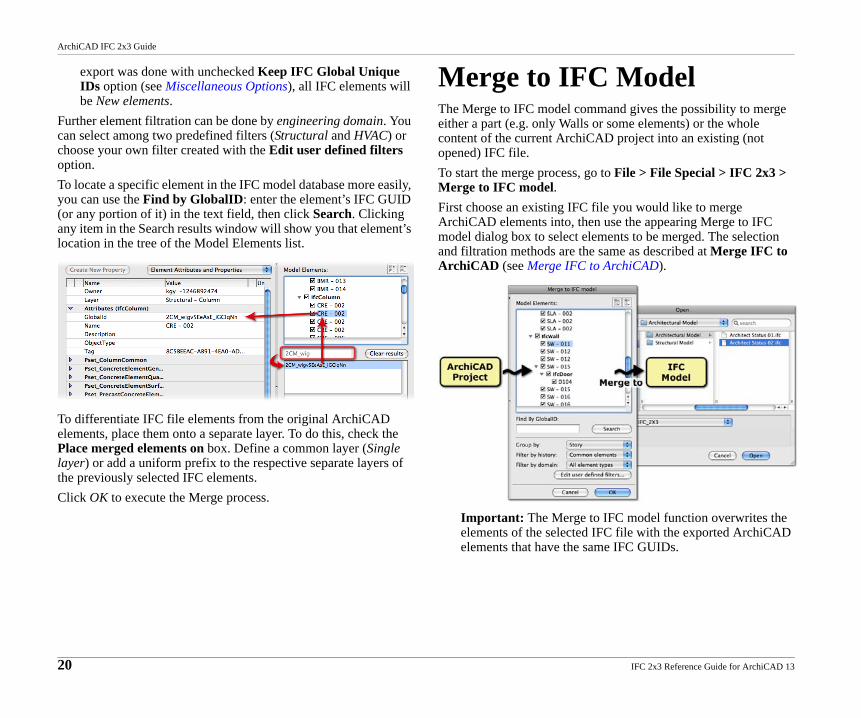
Further element filtration can be done by engineering domain. You can select among two predefined filters (Structural and HVAC) or choose your own filter created with the Edit user defined filters option.To locate a specific element in the IFC model database more easily, you can use the Find by GlobalID: enter the element’s IFC GUID (or any portion of it) in the text field, then click Search. Clicking any item in the Search results window will show you that element’s location in the tree of the Model Elements list.
To differentiate IFC file elements from the original ArchiCAD elements, place them onto a separate layer. To do this, check the Place merged elements on box. Define a common layer (Single layer) or add a uniform prefix to the respective separate layers of the previously selected IFC elements.Click OK to execute the Merge process.
Merge to IFC ModelThe Merge to IFC model command gives the possibility to merge either a part (e.g. only Walls or some elements) or the whole content of the current ArchiCAD project into an existing (not opened) IFC file.To start the merge process, go to File > File Special > IFC 2x3 > Merge to IFC model.First choose an existing IFC file you would like to merge ArchiCAD elements into, then use the appearing Merge to IFC model dialog box to select elements to be merged. The selection and filtration methods are the same as described at Merge IFC to ArchiCAD (see Merge IFC to ArchiCAD).
Important: The Merge to IFC model function overwrites the elements of the selected IFC file with the exported ArchiCAD elements that have the same IFC GUIDs.
20 IFC 2x3 Reference Guide for ArchiCAD 13
ArchiCAD IFC 2x3 Guide
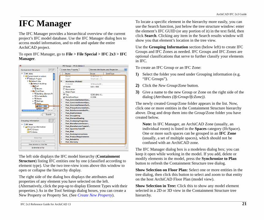
IFC ManagerThe IFC Manager provides a hierarchical overview of the current project’s IFC model database. Use the IFC Manager dialog box to access model information, and to edit and update the entire ArchiCAD project.To open IFC Manager, go to File > File Special > IFC 2x3 > IFC Manager.
The left side displays the IFC model hierarchy (Containment Structure) listing IFC entities one by one (classified according to element type). Use the two tree-view icons above this window to open or collapse the hierarchy display.The right side of the dialog box displays the attributes and properties of any element you have selected on the left. (Alternatively, click the pop-up to display Element Types with their properties.) As in the Tool Settings dialog boxes, you can create a New Property or Property Set. (See Create New Property).
To locate a specific element in the hierarchy more easily, you can use the Search function, just below the tree structure window: enter the element’s IFC GUID (or any portion of it) in the text field, then click Search. Clicking any item in the Search results window will show you that element’s location in the tree view.Use the Grouping Information section (below left) to create IFC Groups and IFC Zones as needed. IFC Groups and IFC Zones are optional classifications that serve to further classify your elements in IFC.To create an IFC Group or an IFC Zone:1) Select the folder you need under Grouping information (e.g.
“IFC Groups”). 2) Click the New Group/Zone button.3) Give a name to the new Group or Zone on the right side of the
dialog (Attributes (IfcGroup/IfcZone)).The newly created Group/Zone folder appears in the list. Now, click one or more entities in the Containment Structure hierarchy above. Drag and drop them into the Group/Zone folder you have created below.
Note: In IFC Manager, an ArchiCAD Zone (usually, an individual room) is listed in the Spaces category (IfcSpace). One or more such spaces can be grouped in an IFC Zone (usually, a set of multiple spaces), which should not be confused with an ArchiCAD zone.
The IFC Manager dialog box is a modeless dialog box; you can keep it open while working in the model. If you add, delete or modify elements in the model, press the Synchronize to Plan button to refresh the Containment Structure tree dialog.Show Selection on Floor Plan: Select one or more entities in the tree dialog, then click this button to select and zoom to that entity on the host ArchiCAD Floor Plan (model view).Show Selection in Tree: Click this to show any model element selected in a 2D or 3D view in the Containment Structure tree hierarchy.
IFC 2x3 Reference Guide for ArchiCAD 13 21
ArchiCAD IFC 2x3 Guide
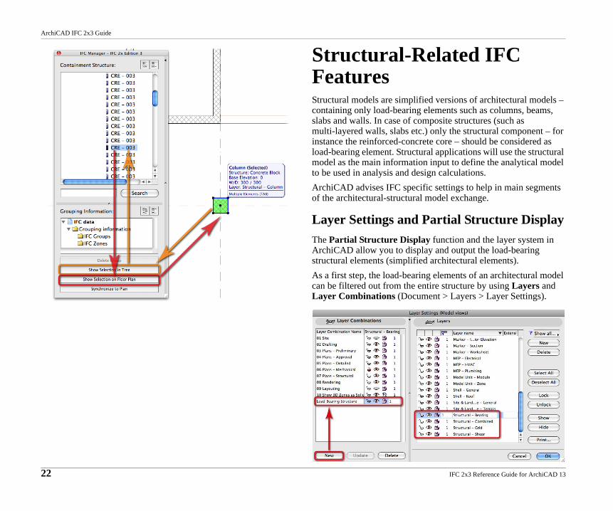
Structural-Related IFC FeaturesStructural models are simplified versions of architectural models – containing only load-bearing elements such as columns, beams, slabs and walls. In case of composite structures (such as multi-layered walls, slabs etc.) only the structural component – for instance the reinforced-concrete core – should be considered as load-bearing element. Structural applications will use the structural model as the main information input to define the analytical model to be used in analysis and design calculations.ArchiCAD advises IFC specific settings to help in main segments of the architectural-structural model exchange.
Layer Settings and Partial Structure DisplayThe Partial Structure Display function and the layer system in ArchiCAD allow you to display and output the load-bearing structural elements (simplified architectural elements).As a first step, the load-bearing elements of an architectural model can be filtered out from the entire structure by using Layers and Layer Combinations (Document > Layers > Layer Settings).
22 IFC 2x3 Reference Guide for ArchiCAD 13
ArchiCAD IFC 2x3 Guide
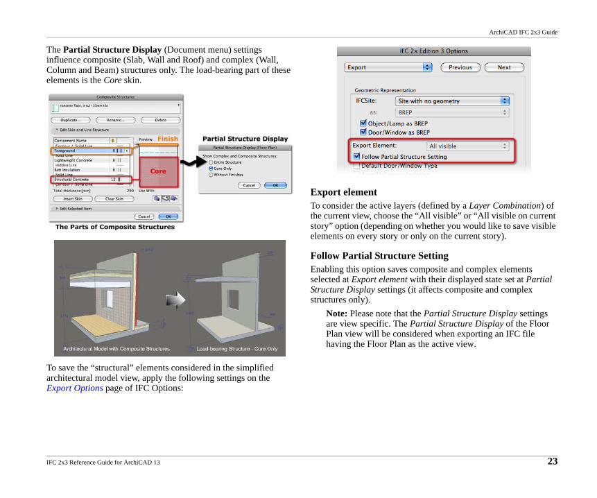
The Partial Structure Display (Document menu) settings influence composite (Slab, Wall and Roof) and complex (Wall, Column and Beam) structures only. The load-bearing part of these elements is the Core skin.
To save the “structural” elements considered in the simplified architectural model view, apply the following settings on the Export Options page of IFC Options:
Export elementTo consider the active layers (defined by a Layer Combination) of the current view, choose the “All visible” or “All visible on current story” option (depending on whether you would like to save visible elements on every story or only on the current story).
Follow Partial Structure SettingEnabling this option saves composite and complex elements selected at Export element with their displayed state set at Partial Structure Display settings (it affects composite and complex structures only).
Note: Please note that the Partial Structure Display settings are view specific. The Partial Structure Display of the Floor Plan view will be considered when exporting an IFC file having the Floor Plan as the active view.
IFC 2x3 Reference Guide for ArchiCAD 13 23
ArchiCAD IFC 2x3 Guide
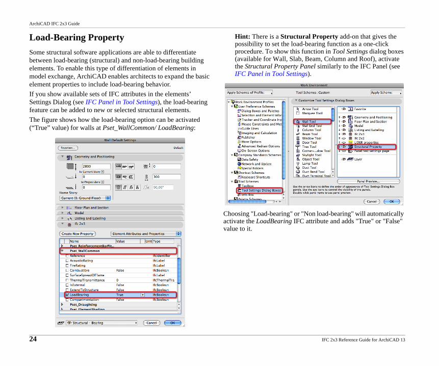
Load-Bearing PropertySome structural software applications are able to differentiate between load-bearing (structural) and non-load-bearing building elements. To enable this type of differentiation of elements in model exchange, ArchiCAD enables architects to expand the basic element properties to include load-bearing behavior.If you show available sets of IFC attributes in the elements’ Settings Dialog (see IFC Panel in Tool Settings), the load-bearing feature can be added to new or selected structural elements.The figure shows how the load-bearing option can be activated (“True” value) for walls at Pset_WallCommon/ LoadBearing:
Hint: There is a Structural Property add-on that gives the possibility to set the load-bearing function as a one-click procedure. To show this function in Tool Settings dialog boxes (available for Wall, Slab, Beam, Column and Roof), activate the Structural Property Panel similarly to the IFC Panel (see IFC Panel in Tool Settings).
Choosing "Load-bearing" or "Non load-bearing" will automatically activate the LoadBearing IFC attribute and adds "True" or "False" value to it.
24 IFC 2x3 Reference Guide for ArchiCAD 13
ArchiCAD IFC 2x3 Guide
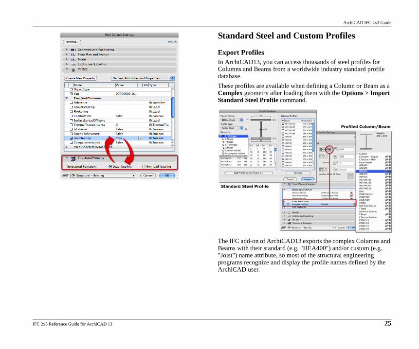
Standard Steel and Custom Profiles
Export ProfilesIn ArchiCAD13, you can access thousands of steel profiles for Columns and Beams from a worldwide industry standard profile database. These profiles are available when defining a Column or Beam as a Complex geometry after loading them with the Options > Import Standard Steel Profile command.
The IFC add-on of ArchiCAD13 exports the complex Columns and Beams with their standard (e.g. "HEA400") and/or custom (e.g. "Joist") name attribute, so most of the structural engineering programs recognize and display the profile names defined by the ArchiCAD user.
IFC 2x3 Reference Guide for ArchiCAD 13 25
ArchiCAD IFC 2x3 Guide
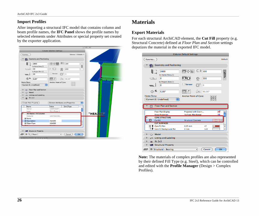
Import Profiles After importing a structural IFC model that contains column and beam profile names, the IFC Panel shows the profile names by selected elements under Attributes or special property set created by the exporter application.
Materials
Export MaterialsFor each structural ArchiCAD element, the Cut Fill property (e.g. Structural Concrete) defined at Floor Plan and Section settings deputizes the material in the exported IFC model.
Note: The materials of complex profiles are also represented by their defined Fill Type (e.g. Steel), which can be controlled and edited with the Profile Manager (Design > Complex Profiles).
26 IFC 2x3 Reference Guide for ArchiCAD 13
ArchiCAD IFC 2x3 Guide
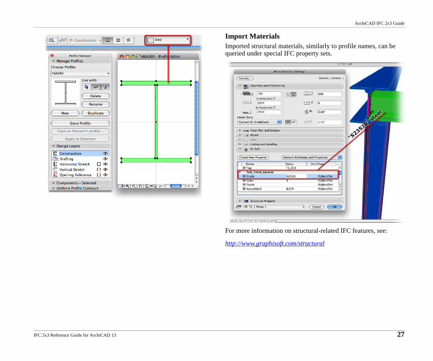
Import Materials Imported structural materials, similarly to profile names, can be queried under special IFC property sets.
For more information on structural-related IFC features, see:
http://www.graphisoft.com/structural
IFC 2x3 Reference Guide for ArchiCAD 13 27
ArchiCAD IFC 2x3 Guide
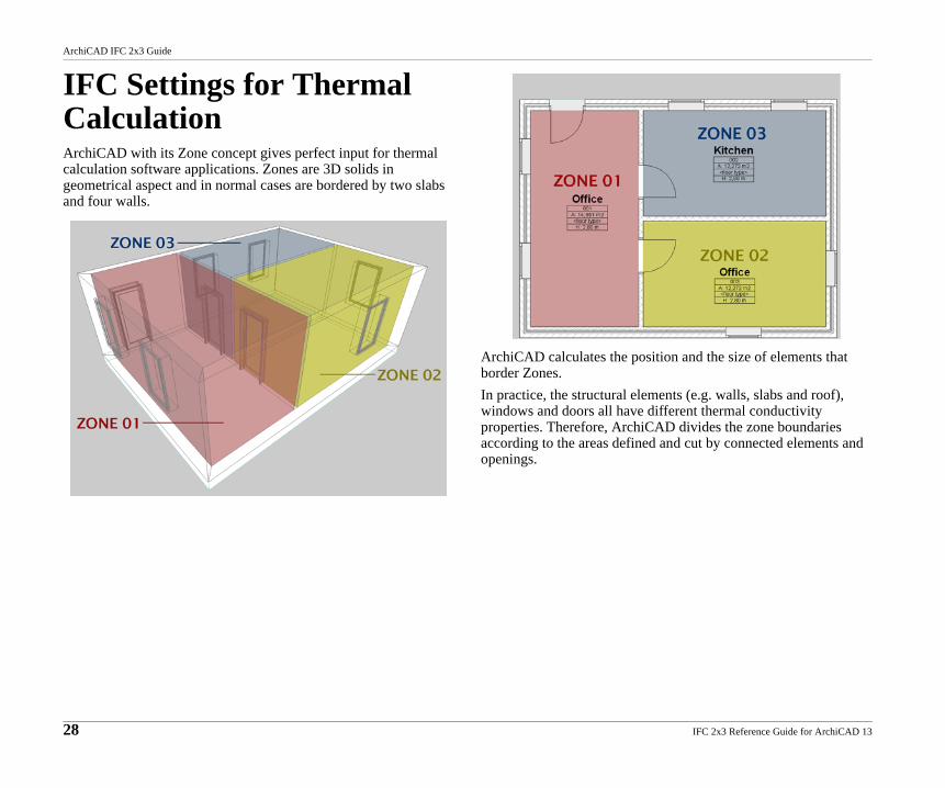
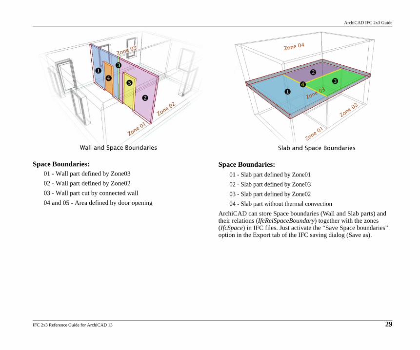
IFC Settings for Thermal CalculationArchiCAD with its Zone concept gives perfect input for thermal calculation software applications. Zones are 3D solids in geometrical aspect and in normal cases are bordered by two slabs and four walls.
ArchiCAD calculates the position and the size of elements that border Zones.In practice, the structural elements (e.g. walls, slabs and roof), windows and doors all have different thermal conductivity properties. Therefore, ArchiCAD divides the zone boundaries according to the areas defined and cut by connected elements and openings.
28 IFC 2x3 Reference Guide for ArchiCAD 13
ArchiCAD IFC 2x3 Guide
Space Boundaries:01 - Wall part defined by Zone0302 - Wall part defined by Zone0203 - Wall part cut by connected wall04 and 05 - Area defined by door opening
Space Boundaries:01 - Slab part defined by Zone0102 - Slab part defined by Zone0303 - Slab part defined by Zone0204 - Slab part without thermal convection
ArchiCAD can store Space boundaries (Wall and Slab parts) and their relations (IfcRelSpaceBoundary) together with the zones (IfcSpace) in IFC files. Just activate the “Save Space boundaries” option in the Export tab of the IFC saving dialog (Save as).
IFC 2x3 Reference Guide for ArchiCAD 13 29
ArchiCAD IFC 2x3 Guide
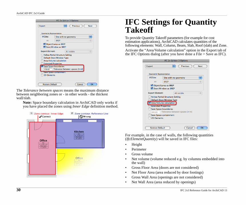
The Tolerance between spaces means the maximum distance between neighboring zones or - in other words - the thickest wall/slab.
Note: Space boundary calculation in ArchiCAD only works if you have placed the zones using Inner Edge definition method.
IFC Settings for Quantity TakeoffTo provide Quantity Takeoff parameters (for example for cost estimation applications), ArchiCAD calculates quantities of the following elements: Wall, Column, Beam, Slab, Roof (slab) and Zone.Activate the “Area/Volume calculation” option in the Export tab of the IFC Options dialog (after you have done a File > Save as IFC).
For example, in the case of walls, the following quantities (IfcElementQuantity) will be saved in IFC files:• Height• Perimeter• Gross volume• Net volume (volume reduced e.g. by columns embedded into
the wall)• Gross Floor Area (doors are not considered)• Net Floor Area (area reduced by door footings)• Gross Wall Area (openings are not considered)• Net Wall Area (area reduced by openings)
30 IFC 2x3 Reference Guide for ArchiCAD 13