aquatic center
DESCRIPTION
demoTRANSCRIPT
Images of Aquatic Center(Exterior):
Images of Aquatic Center(Interior):
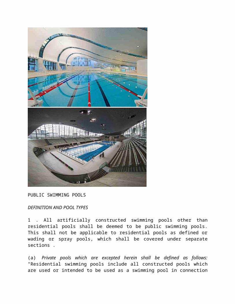
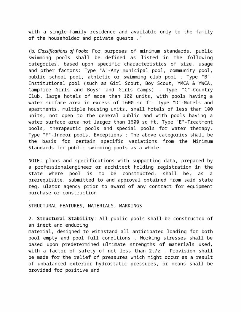
PUBLIC SWIMMING POOLS
DEFINITION AND POOL TYPES
1 . All artificially constructed swimming pools other than residential pools shall be deemed to be public swimming pools. This shall not be applicable to residential pools as defined or wading or spray pools, which shall be covered under separate sections .
(a) Private pools which are excepted herein shall be defined as follows: "Residential swimming pools include all constructed pools which are used or intended to be used as a swimming pool in connection with a single-family residence and available only to the family of the householder and private guests ."
(b) Classifications of Pools: For purposes of minimum standards, public swimming pools shall be defined as listed in the following categories, based upon specific characteristics of size, usage and other factors: Type "A"-Any municipal pool, community pool, public school pool, athletic or swimming club pool . Type "B"-Institutional pool (such as Girl Scout, Boy Scout, YMCA & YWCA, Campfire Girls and Boys' and Girls Camps) . Type "C"-Country Club, large hotels of more than 100 units, with pools having a water surface area in excess of 1600 sq ft. Type "D"-Motels and apartments, multiple housing units, small hotels of less than 100 units, not open to the general public and with pools having a water surface area not larger than 1600 sq ft. Type "E"-Treatment pools, therapeutic pools and special pools for water therapy. Type "F"-Indoor pools. Exceptions : The above categories shall be the basis for certain specific variations from the Minimum Standards for public swimming pools as a whole.
NOTE: plans and specifications with supporting data, prepared by a professionalengineer or architect holding registration in the state where pool is to be constructed, shall be, as a prerequisite, submitted to and approval obtained from said state reg. ulator agency prior to award of any contract for equipment purchase or construction.STRUCTURAL FEATURES, MATERIALS, MARKINGS
2. Structural Stability: All public pools shall be constructed of an inert and enduringmaterial, designed to withstand all anticipated loading for both pool empty and pool full conditions . Working stresses shall be based upon predetermined ultimate strengths of materials used, with a factor of safety of not less than 2t/z . Provision shall be made for the relief of pressures which might occur as a result of unbalanced exterior hydrostatic pressures, or means shall be provided for positive and
-continuous drainage from under the pool floor or around the pool walls, whetherground water is present, or might occur at some future time .Special provisions shall be made to protect the pool structures from both internal and external stresses which may develop due to freezing in cold climates .
3. Obstructions : There shall be no obstruction extending from the wall or thefloor, extending into the clear area of the diving portion of the pool . There shall bea completely unobstructed clear distance of 13 ft above the diving board.
4. Wall & Floor Finish : Wall and floor finish shall be of masonry, tile or other inert and impervious material and shall be reasonably enduring . Finish shall be moderately smooth and of a white or light color.
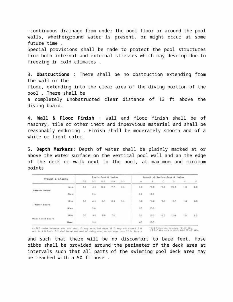
5. Depth Markers: Depth of water shall be plainly marked at or above the water surface on the vertical pool wall and an the edge of the deck or walk next to the pool, at maximum and minimum points
and such that there will be no discomfort to bare feet. Hose bibbs shall be provided around the perimeter of the deck area at intervals such that all parts of the swimming pool deck area may be reached with a 50 ft hose .
6 . Fence: A wall or other enclosure of 4 ft minimum height and with maximum 2 in . mesh, 2 in . wide vertical openings, or otherwise so constructed as to be difficult to climb, shall be provided completely enclosing the pool area, all of which shall be paved .Exceptions may be made for Types C & D In Types C & D where the fence is dispensed with, a hedge or other clear demarcation shall be provided, with instructions and posting clearly defining the pool area as for bathers only and from which spectators and others in street clothes ore rigidly excluded .
Access to the pool by bathers shall be provided only through the bathhouse or dressing
room facilities, and any other fence opening shall be for service operations only.
GUTTERS AND SKIMMERS
7 . Overflow Gutters: An overflow gutter shall be installed continuous around all public swimming pools, with the exception that it may be eliminated in Types B, C, D & E. The overflow gutter may be eliminated across the top tread where steps occur.Overflow gutter shape, wherein the outer edge of the lip is flush with the pool wall above and below and the gutter entirely recessed, shall not be permitted. The overflow gutter depth below the overflow lip shall be a minimum of 2 in . at the high points between drains. The drains shall be spaced at a maximum of 15 ft on centers and a slope provided in the bottom of not less than 21/z in . in 10 ft. In no sense is this intended to preclude the use of roll-out or deck level type pools where other conditions are met and satisfactory design is provided . In an installation where the overflow gutter is not carried to waste but is a part of the recirculation system, the provisions of spacing of drains and slope at bottom of gutter may be modified but shall conform to good hydraulic design .
The branch piping to each overflow gutter drain shall be not less than 2 in .:s of an irregular shape such as the leg of a T,LorZ .
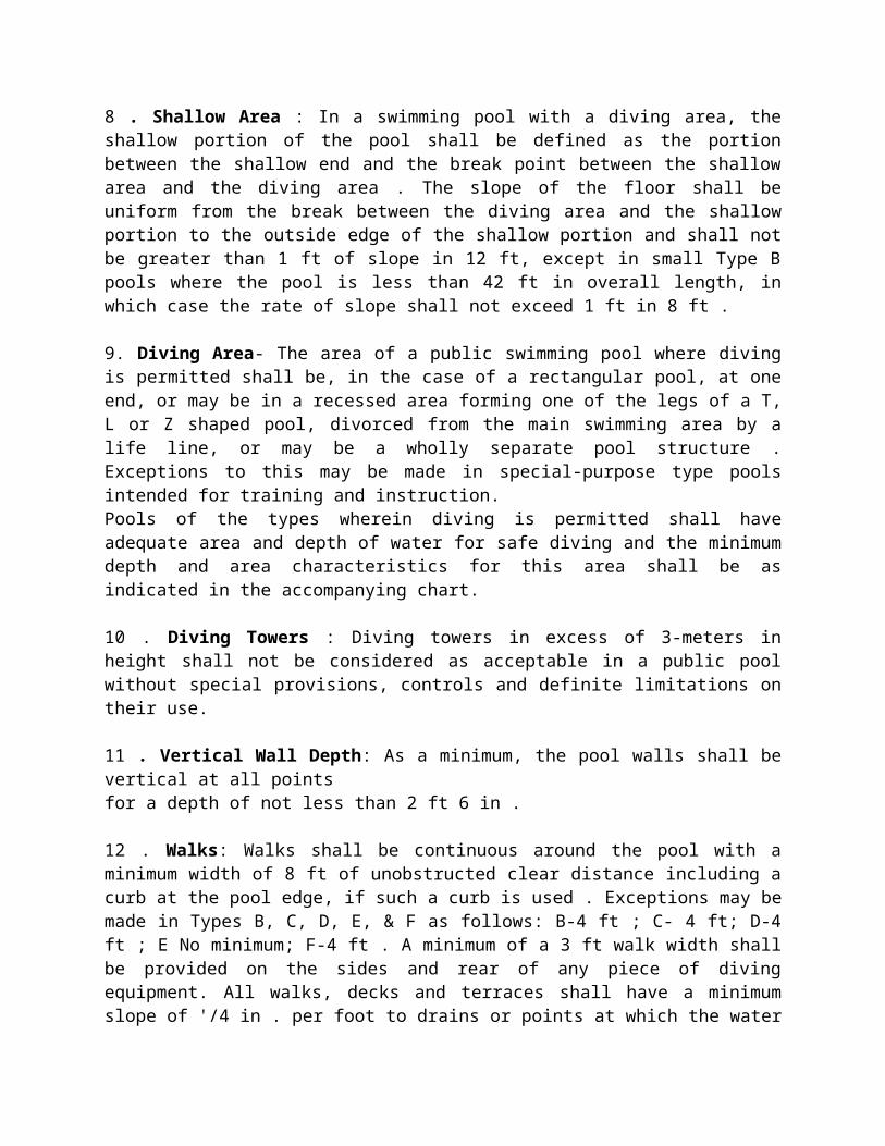
8 . Shallow Area : In a swimming pool with a diving area, the shallow portion of the pool shall be defined as the portion between the shallow end and the break point between the shallow area and the diving area . The slope of the floor shall be uniform from the break between the diving area and the shallow portion to the outside edge of the shallow portion and shall not be greater than 1 ft of slope in 12 ft, except in small Type B pools where the pool is less than 42 ft in overall length, in which case the rate of slope shall not exceed 1 ft in 8 ft .
9. Diving Area- The area of a public swimming pool where diving is permitted shall be, in the case of a rectangular pool, at one end, or may be in a recessed area forming one of the legs of a T, L or Z shaped pool, divorced from the main swimming area by a life line, or may be a wholly separate pool structure . Exceptions to this may be made in special-purpose type pools intended for training and instruction.Pools of the types wherein diving is permitted shall have adequate area and depth of water for safe diving and the minimum depth and area characteristics for this area shall be as indicated in the accompanying chart.
10 . Diving Towers : Diving towers in excess of 3-meters in height shall not be considered as acceptable in a public pool without special provisions, controls and definite limitations on their use.
11 . Vertical Wall Depth: As a minimum, the pool walls shall be vertical at all pointsfor a depth of not less than 2 ft 6 in .
12 . Walks: Walks shall be continuous around the pool with a minimum width of 8 ft of unobstructed clear distance including a curb at the pool edge, if such a curb is used . Exceptions may be made in Types B, C, D, E, & F as follows: B-4 ft ; C- 4 ft; D-4 ft ; E No minimum; F-4 ft . A minimum of a 3 ft walk width shall be provided on the sides and rear of any piece of diving equipment. All walks, decks and terraces shall have a minimum slope of '/4 in . per foot to drains or points at which the water will have a free unobstructed flow to points of disposal at all times. and at the points of break between the deep and shallow portions and at intermediate increments of depth, spaced at not more than 25 ft intervals. Depth markers shall be in numerals of 4 in . min . height and of a color contrasting with background . Markers shall be on both sides and ends ofthe pool .
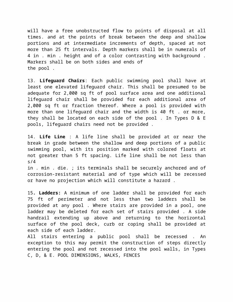
13. Lifeguard Chairs: Each public swimming pool shall have at least one elevated lifeguard chair. This shall be presumed to be adequate for 2,000 sq ft of pool surface area and one additional lifeguard chair shall be provided for each additional area of 2,000 sq ft or fraction thereof. Where a pool is provided with more than one lifeguard chair and the width is 40 ft . or more, they shall be located on each side of the pool . In Types D & E pools, lifeguard chairs need not be provided .
14. Life Line : A life line shall be provided at or near the break in grade between the shallow and deep portions of a public swimming pool, with its position marked with colored floats at not greater than 5 ft spacing. Life line shall be not less than s/4in . min . die. ; its terminals shall be securely anchored and of corrosion-resistant material and of type which will be recessed or have no projection which will constitute a hazard .
15. Ladders: A minimum of one ladder shall be provided for each 75 ft of perimeter and not less than two ladders shall be provided at any pool . Where stairs are provided in a pool, one ladder may be deleted for each set of stairs provided . A side handrail extending up above and returning to the horizontal surface of the pool deck, curb or coping shall be provided at each side of each ladder.All stairs entering a public pool shall be recessed . An exception to this may permit the construction of steps directly entering the pool and not recessed into the pool walls, in Types C, D, & E. POOL DIMENSIONS, WALKS, FENCES
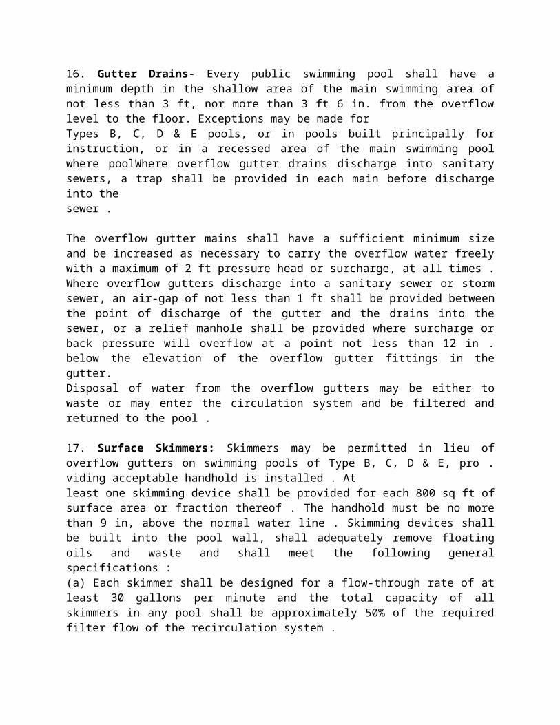
16. Gutter Drains- Every public swimming pool shall have a minimum depth in the shallow area of the main swimming area of not less than 3 ft, nor more than 3 ft 6 in. from the overflow level to the floor. Exceptions may be made forTypes B, C, D & E pools, or in pools built principally for instruction, or in a recessed area of the main swimming pool where poolWhere overflow gutter drains discharge into sanitary sewers, a trap shall be provided in each main before discharge into thesewer .
The overflow gutter mains shall have a sufficient minimum size and be increased as necessary to carry the overflow water freely with a maximum of 2 ft pressure head or surcharge, at all times . Where overflow gutters discharge into a sanitary sewer or storm sewer, an air-gap of not less than 1 ft shall be provided between the point of discharge of the gutter and the drains into the sewer, or a relief manhole shall be provided where surcharge or back pressure will overflow at a point not less than 12 in . below the elevation of the overflow gutter fittings in the gutter.Disposal of water from the overflow gutters may be either to waste or may enter the circulation system and be filtered and returned to the pool .
17. Surface Skimmers: Skimmers may be permitted in lieu of overflow gutters on swimming pools of Type B, C, D & E, pro . viding acceptable handhold is installed . Atleast one skimming device shall be provided for each 800 sq ft of surface area or fraction thereof . The handhold must be no more than 9 in, above the normal water line . Skimming devices shall be built into the pool wall, shall adequately remove floating oils and waste and shall meet the following general specifications :(a) Each skimmer shall be designed for a flow-through rate of at least 30 gallons per minute and the total capacity of all skimmers in any pool shall be approximately 50% of the required filter flow of the recirculation system .(b) They shall be automatically adjustable to variations in water level over a range of at least 3 in .(c) An easily removable and cleanable basket or screen through which all overflow water must pass shall be provided to trap large solids .(d) The skimmer shall be provided with a device to prevent airlock in the suction line . If an equalizer pipe is used, it shall provide an adequate amount of makeup water for pump suction, should the water of the pool drop below the weir level . This pipe shall be at least 2 in . i n diameter and shall be located at least 1 ft below the lowest overflow level of the skimmer .
Recreation and Entertainment
SWIMMING POOLS
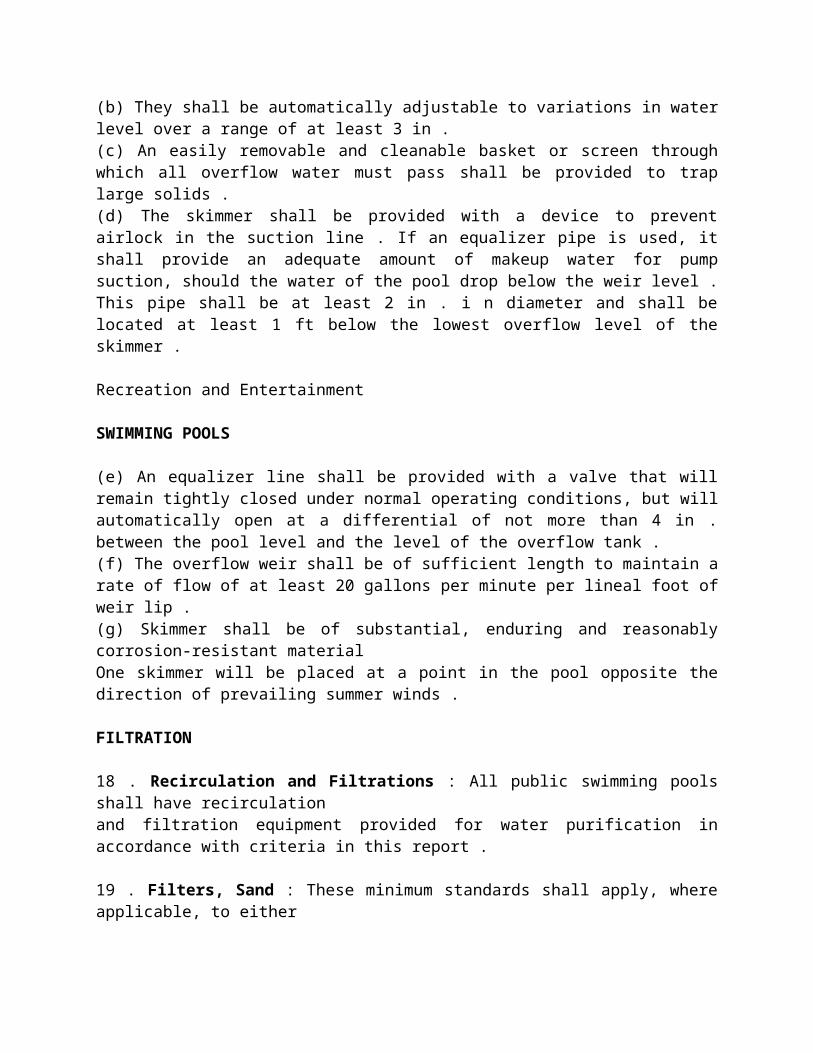
(e) An equalizer line shall be provided with a valve that will remain tightly closed under normal operating conditions, but will automatically open at a differential of not more than 4 in . between the pool level and the level of the overflow tank .(f) The overflow weir shall be of sufficient length to maintain a rate of flow of at least 20 gallons per minute per lineal foot of weir lip .(g) Skimmer shall be of substantial, enduring and reasonably corrosion-resistant materialOne skimmer will be placed at a point in the pool opposite the direction of prevailing summer winds .
FILTRATION
18 . Recirculation and Filtrations : All public swimming pools shall have recirculationand filtration equipment provided for water purification in accordance with criteria in this report .
19 . Filters, Sand : These minimum standards shall apply, where applicable, to eithergravity or pressure sand filters . Filter tanks shall be designed with a factor of safety of 4 in relation of working pressure to ultimate strength .The filter bed shall consist of suitable grades of filter sand and a supporting bed of graded gravel or other porous material which shall serve to support the filter bed and distribute both filtered and backwash water uniformly . The supporting bed consisting of graded gravel or other material shall support not less than 20 in . of filter media consisting of silica sand or other durable, inert material with an effective size between 0 .4 and 0 .55 mm, and a uniformity coefficient not exceeding 1 .75.
The minimum freeboard to the draw-off point shall be not less than 12 in . above the normal level of the top of the filter bed . The minimum backwash rate shall be not less than 12 gallons per square foot of filter bed per minute .Where anthracite coal or other filter media is employed, the freeboard shall be adequateto prevent the media being carried off to waste when the filter bed is backwashed at a rate adequate to carry off foreign material filtered from the water .The freeboard and the rate of backwash shall be the subject of individual design, based upon specific gravity of the media .Under-drain system shall be such that uniform distribution of backwash water shall be provided over the entire bed area .Ratio of total under-drain orifice area to total area of bed shall be not less than 0 .25 per cent .
Orifices in the under-drain system shall be spaced at approximately b in . on centersboth ways throughout the area of filter bed . The total orifice area may be provided by means of porosity of the material over the total under-drain area . Under-drain system shall be provided of material which is corrosion-resistant and enduring, wherein the orifices shall be so designed and of such material that they will maintain approximately constant area, Where the under-drain system is of manifold and lateral type, the total area of the manifold shall be equal to not less than the total area of the laterals . The total area of the laterals shall be not less than 1' .4 timesthe total area of the orifices .
Design rate for sand filters shall be 3 gallons per minute, per square foot of bed area, as a minimum standard . The filter plant shall be provided with influent and effluent pressure gauges, backwash sight glass and air-relief valves .The filter plant shall be provided with face piping and valving to permit the functions of filtering to pool or backwashing to waste with the battery as a whole or any unit operated singly .The filter plant shall be provided with means for draining all filter units and piping, so that all parts of the system may be completely drained to prevent damage from freezing.Each filter unit shall be provided with an access opening of not less than a standard 11 in . b y 15 in . manhole and cover . Pressure filter tanks shall be supported by jack legs or other supports to give a free movement of air under each tank and to permit access for painting .Filter turn-over cycle shall be of capacity to completely filter the entirentire pool body in not more than 8 hours .
20. Filters, Diatomite: Where diatomite filters are used, they may be of either pressure or vacuum type . The filter rate shall not exceed 2 .5 gpm per square foot of filtersurface area .The cycle of operation between cleaning of the diatomite filters shall be not less than a 24 hr period of continuous operation and this shall not be deemed to apply to initial operation of a pool, but only after operation for a period of 3 days or such period as is necessary to initially clear the pool .Provisions shall be made to introduce a pre-coat to completely cover the filter elements, upon placing the equipment in initial operation and/or after each cleaning .The equipment shall be so arranged that during pre-coating, the effluent will be refiltered or disposed to waste without passing into the pool until the effluent is clear ofsuspended matter . Equipment shall be provided for the continuousfeed of filter aid to the filter influent and the equipment shall have a capacity to feed not less than 0.1 Ib of this material per square foot of filter area over a 24 hour period .
Exceptions to the above may be made in Types B, C, D, E & F pools, in cases where this equipment need not be provided . The tank containing the diatomite filter elementsshall be constructed of intermediate carbon steel, plastic or other suitable material which will satisfactorily provide resistance to corrosion, with or without coating, and shall be of adequate strength to resist all stresses resulting from loading with a factor of safety of 4, in relation to the ultimate strength .The septum or elements which support the filter aid shall be of corrosion-resistant material and shall be provided with openings, the minimum dimension of which shall be not greater than 0.005 in .The septa shall be constructed to be adequately resistant against crushing or deformotion, with the maximum differential pressure between influent and effluent of not less than the maximum pressure which can be developed by the circulating pump and of adequate strength to resist the stress es developed by the cleaning operation, with the impact developed from an acceler. ated washing operation .In the complete filter installation, where dissimilar metals are used which may set up galvanic electric currents, the metals shall be insulated with a suitable dielectric which will satisfactorily prevent corrosion from electrolysis . The filters shall be designed and installed in such a manner that they can be readily disassembled and elements removed and they shall not be installed where inadequate working space above or around is available for such disassembling.The filter plant shall be provided with pres . sure differential gages and air-relief outlets where necessary.
21 . Filters, Other: In the absence of complete information on operating characteristics, durability, etc., of cartridge and other type filters, no minimum standards can be established at this time and their installation on public pools may only be made on a trial basis.
22 . Compound Gauge: The pump suction header shall be provided with a compoundgauge between the pump strainer and the pump, which will indicate both positive and negative head.
23 . Strainers: At all pressure type filter plants or where the circulating pump is used for vacuum cleaning the pool, a suitable strainer or screen shall be provided to remove solids, debris, hair, lint, etc. Where a wet well is provided, the strainer shall consist of a removable screen through which all water entering the pump shall pass . Where no wet well is provided or where the suction cleaner or any other suction line is piped directly from the pool to the pumps, a pot-type strainer with removable strainer basket shall be provided . The strainer basket shall be of rigid construction sufficiently strong
to prevent collapsing when clogged. One extra strainer basket shall be provided .Any type of screen or strainer basket shall be fabricated of a corrosion-resistant material or shall have a protective coating of such material .Screen of strainer basket shall have maximum openings no greater than 3/4 the sizeof the solids which will pass through the pump impeller without clogging and the total clear area of all openings shall be not less than 4 times the area of the largest sized pipe from the pool to the strainer influent.
24 . Rate-of-Flow Indicator: Every swimming pool provided with recirculation and refiltration system shall be provided with a rate-of-flow indicator on the pump dischargeline leading to the filters and shall be calibrated for measuring both water for filtration and backwash and the activating element creating the pressure differential for indication of flow shall be installed with adequate clear distance upstream and downstream to obtain a reasonable degree of accuracy .
The rate indicator shall be calibrated for and provided with a scale reading in gallons per minute and shall have a range of 10% below the established filtration rate and 10% above the backwash rate established.
Where diatomite filters are used, the activating element of the flow indicator shall be installed in the filter effluent line .
POOL POPULATION,SANITARY FACILITIES
25 . Capacity of Pool in Bathers: The maximum number of persons in bathing attire within the pool enclosure or the bathing area shall be limited to one person per 20 sq ft of pool and deck area combined . 26. Bathhouse: Adequate dressing and sanitary plumbing facilities shall be provided for every public swimming pool . An exception to this may be made in Types B, C, D, E & F pools where available facilities are provided in connection with the general development for other purposes, etc., of adequate capacity and number, in close proximity to the pool .Every bathhouse shall be provided with separate facilities for each sex with no interconnection between the provisions for male and female. The rooms shall be well . lighted, drained, ventilated and of good con. struction, with impervious materials employed in general, finished in light colors and so developed and planned that goodsanitation can be maintained throughout the building at all times.
(a) Minimum sanitary plumbing facilities shall be provided as follows:
Males: One water closet combination, one lavatory and one urinal shall be presumed to be adequate for the first 100 bothers.One water closet and one urinal shall be provided for each additional 150 bathers or major fraction thereof. One lavatory shall be provided for each 200 additional bathers.A minimum of three shower heads shall be provided which shall be presumed to be adequate for the first 150 males and one shower outlet shall be provided for each additional 50 male bathers.
Females: A minimum of two water closet combinations shall be provided in each bathhouse building and this shall be presumed to be adequate for the first 100 fe . males.One additional water closet combination shall be provided for each additional 75 females or fraction thereof. A minimum of two shower heads shall be provided, which shall be presumed to be adequate for the first 100 females and one shower shall be added for each 50 ad . ditional females.One lavatory shall be provided as a minimum, which shall be considered adequate for the first 75 females. One additional lavatory shall be provided for each additional 75 females in attendance, or major fraction thereof.These minimum criteria for bathhouse plumbing facilities shall be based upon the anticipated maximum attendance in bathers. Facilities for either sex shall be based upon a ratio of 60% of the total number of bathers being male and 40% being female.Shower and dressing booths shall be provided in female dressing space and dressing booths shall be provided with curtains or other means of seclusion. This condition may be subject to variation for schools and other institutional use where a pool may be open only to one sex at a time .
(b) Drinking Fountain : Not less than one drinking fountain shall be provided available to bathers both at the pool and in the bathhouse.
(c) Hose flibbs : Hose bibbs shall be provided for flushing down the dressing roomsand bathhouse interior . The floors of the bathhouse shall be concrete, free of joints or openings and shall be continuous throughout the area with a very slight texture to minimize slipping but which shall be relatively smooth to ensure complete cleaning . Floor drains shall be provided to ensure positive drainage of all parts of the building with a slope in the floor of not less than 1/4 in . per foot, toward drains.
Recreation and Entertainment
SWIMMING POOLS
(d) Hot Water: Heated water will be provided at all shower heads. Water heater and thermostatic mixing valve shall be inaccessible to bathers and

will be capable of providing 2 gpm of 90 F. water to each shower head, and no other water shall be supplied .
No differences in elevation, requiring steps, shall be provided in the interior of male and female dressing areas. No steps shall be permitted between the bathhouse and the pool deck areas adjoining and should it be necessary that the bathhouse floor be at a different elevation from the pool decks, ramps shall be provided at the access doors. Where romps are used between the bathhouse and pool decks, the slope shall not exceed 3 in . per ft and shall be positively non-slip .All partitions between portions of the dressing room areas, screen partitions, shower, toilet and dressing room booths shall be of durable material not subject to damage by water and shall be so designed that a water way is provided between the partitions and floor to permit thorough cleaning of the floor area with hoses and brooms .
(e) Soap dispensers : Soap dispensers for providing either liquid or powdered soap shall be provided at each lavatory and between each pair of shower heads and dispensers must be of all-metal or plastic type and no gloss permitted in these units.
(f) Mirrors: Mirrors shall be provided over each lavatory and toilet paper holders shall be provided at each water closet combination.(g) Water: All water provided for drinking fountains, lavatories and showers shall be potable and meet the requirements and conform with the standards of the U . S. Public Health Service.
27 . Food Service: Where provision is made for serving food and/or beverages at the pool, no containers of glass or other material which might be a hazard to bothers' feet, when broken, shall be used . The area shall be so arranged and posted to prohibit the consumption of food and beverages on the pool decks proper .
ELECTRICAL REQUIREMENTS
28 . Lighting and Wiring(a) Submarine Lighting : Where submarine lighting is used, not less than 0.5 watts shall be employed per square foot of pool area .(b) Area Lighting : Where submarine light. ing is employed, area lighting shall be provided for the deck areas and directed toward the deck areas and away from the pool surface insofar as practical in a total capacity of not less than 0.6 watts per square foot of deck area . Where submarine lighting is not employed and night swimming is permitted, area and pool lighting combined shall be provided in an amount of not less than 2 watts per square foot of total area .
(c) All wiring in connection with requirements for a swimming pool for lighting or power shall conform with the codes of the National Underwriters' Laboratories (National Electric Code).(d) In addition to any other grounding, each submarine light unit shall be individually grounded by means of a screwed or bolted connection to the metal junction box from which the branch circuit to the individual light proceeds .'e) Overhead Wiring : No electrical wiring for lighting or power shall be permitted to pass overhead within 20 ft of the pool enclosure.
DRAINAGE PIPING
29. Mechanical Pool Fittings : Where overflow gutters are installed, outlet spacing shall not be greater than 15 ft on centers.Overflow gutter branch lines from each drain fitting shall be not less than 2 in . I .P .S .Pool inlets and outlets shall be provided and arranged to produce a uniform circulation of water and the maintenance of uni. form chlorine residual throughout the pool ; there shall be at least four inlets for the smallest pool .Provisions shall be made to adjust the flow through all inlets. Maximum flow rates (in gpm) through various sized inlet branches shall be not more than as follows: Size & gpm; 1 in. = 10 ; 1!4 in . =20; 1Yzin.=30;2in.=50.In pools with surface area greater than 1500 sq ft or length in excess of 60 ft, inlets shall be placed around the entire perimeter. In any case, an adequate num. ber of inlets shall be provided, properly spaced and located to accomplish complete recirculation and the maintenance of a uniform and adequate sterilizing medium at all times.
30. Main Drain Spacing: When the outlets to pool pump suction are installed near the end of a pool, the spacing shall be not greater than 20 ft on centers. An outlet shall be provided not more than 15 ft from side wall .The outlet grate clear area shall be such that when the maximum flow of water is being pumped through the floor outlet, the velocity through the clear area of the grate shall not be greater than l'/i ft per second .Outlet grates shall be anchored and openings in grates shall be slotted and theminimum dimension of slots shall be not more than '/2 in . Where outlet fittings consist of parallel plates, of so-called anti-vortex type where the water enters the fittings from the sides rather than through a grating facing upward, entrance velocities may be increased to b ft per second. All pool fittings shall be of non-corrosive material .
31 . Piping : The determination of sizes of pipe, fittings and valves on the complete main pump suction line from the swimming pool shall be based upon a rate of friction losses for piping of not more than 6 ft per 100 ft of pipe, based upon Hazen-Williams formulas for 15-year old piping . All piping
on the discharge side of the pump for filtration and to the point for discharge of backwash water from the filter plant shall have pipe sizes determined on a basis of friction losses which shall be not more than 12 ft per 100 ft and the velocity in any pipe shall not exceed 10 ft per second and pipe selection shall be made based upon Hazen-Williams formulas for 15-year old pipe . In the determination of pipe sizes required, the criterion which would call for the largest pipe size shall govern .All pool piping shall be supported by piers or otherwise to preclude against possible settlement which will either provide dirt traps or air pockets and a condition which would rasult in rupture of the lines. All pressure and suction lines shall have a uniform slope in one direction of not less than 3 in . per 100 ft . Gravity waste lines around the pool 6 in . or smaller shall have a minimum slope of '/é in . per ft .Lines larger than 6 in . and all outfolf waste mains shall be designed with a size of pipeand slope to freely carry the maximum flows required with no surcharge or back pressure in the lines. All piping and equipment shall be provided with positive means of completely draining all water to prevent damage from freezing .
32. Direct Connections to Utilities: No direct mechanical connection between a source of domestic water supply shall be made to a swimming pool or to its piping, thereby eliminating a cross connection to what may become a source of contamination.
The water supply for filling the pool, when derived from a potable supply, shall be by means of an over-fall fillspout to the pool, or an over-fall supply to a surge tank, wherein the water will freely overflow at deck level or the top of the surge tank, before coming into contact with the water supply outlet .The disposition of sanitary sewage from the bathhouse shall be into a sanitary sewer, a septic tank or other waste line which meets with the approval of local health authorities.Whenever any waste from the swimming pool is connected to a sanitary sewer or a storm sewer, an air-gap or a relief manhole shall be provided which will positively preclude against surge or backflow introducing contaminated water into the swimming pool or the water treatment plant as covered elsewhere.
33 . Pump and Motor: Pump and motor unit shall be provided for recirculation of the pool water which has been selected for performance and will meet the conditions of quantity required for filtering and cleaning the filters with the total dynamic head developed by the complete system . The requirements for filtration shall be based upon the maximum head loss developed immediately prior to washing the filters . Themotor shall be non-overloading in continuous operation for filtration under all conditions but may be overloaded within the service factor for conditions of
backwash and for emptying the pool . Pump performance curve for the unit to be installed shall be provided and submitted to proper authorities .
34. Vacuum Cleaner: Where facilities are installed integrally in the pool piping system for the operation of a vacuum cleaner, the piping shall be required to produce not more than 15 ft total head loss at the pump, while moving four gallons per minute per lineal inch of cleaner head .
35. Sterilizing Agent: Some means of sterilizing the pool water shall be used which provides a residual of sterilizing agent in the pool water. Either chlorine or bromine may be used for this purpose. In either case, adequate feeding equipment and equipment for testing residuals must be employed . Inasmuch as chlorine is almost universally used, minimum standards for the use of chlorine are given below .In all public pools, chlorine shall be supplied by means of a gas chlorinator which controls and introduces the chlorine gas into water solution and introduces it into the pool water. Exceptions to this may be made in Types B, C, D, E & F swimming pools, where chlorine may be applied in the form of hypochlorites fed by a positive feed pump suitable for use with hypochlorite in solution .Equipment for supplying chlorine or compounds of chlorine shall be of capacity to feed 1 Ib of available chlorine per 3000 gallons of pool volume per 24-hour period .This may be reduced by 50% for Type E pools.
36 . Instructions: All valves shall be permanently tagged and valve operating scheduleshall be provided for every operation. Instructions shall be supplied in not less than two copies .
POOL WATER AND TREATMENT
37. Chlorine Compartment: Where gaseous chlorine equipment is provided below grade in a filter room or in any part of a building which provides housing, the mechanical proportioning device and cylinders of chlorine shall be housed in a reasonably gas-light corrosion-resistant and mechanically vented enclosure. Air-tight duct from the bottom of the enclosure to atmosphere in on unrestricted area and a motor-driven exhaust fan capable of producing at least one air change per minute shall be pro. vided . Automatic louvers of good design near the top of the enclosure for admitting fresh air are required . An opening at least 18 in . square, glazed with clear glass, and artificial illumination shall be provided in an amount such that the essential performance of the equipment may be observed, at all times, without opening the enclosure.Electrical switches for the control of artificial lighting and ventilation shall be on the outside of the enclosure adjacent to the door . The floor area of the
enclosure shall be of adequate size to house the chlorinater, fan, scales and one extra chlorine cylinder . Gas mask approved by the Bureau of Mines for protection against chlorine gas shall be provided, mounted outside the chlorine compartment.
33 . Coagulant Feeder : Coagulant feeder of cast-iron pot type with piping arranged to provide a restriction in the flow or other means of creating a pressure differential which will circulate a portion of the filter influent on a ratio proportionate to the rate of flow shall be provided . Pot shall be of good grade gray cast iron with quick-removable, tight-gasketed cover and will be piped with IPS brass pipe to circulate through the feeder with a tapping at the bottom of the feeder for entering water and a tapping at the top for supplying coagulant solution to the filter influent . Control valves, one of which shall be needlepoint type, and a drain cock for draining the equipment when the plant is out of operation shall be provided. The capacity of the pot shall be not less than 2 oz of lump or nut potassium alum per square foot of filter bed area .
39. Testing Equipment: A test set shall be provided for the determination of free chlorine residual and the pH hydrogen-ion content in the pool water of calorimetric type with test tubes and supply of phenol red solution and orthotoluidine agents . Color standards shall be as follows and the carrying case and test tubes shall be provided of plastic or other material which is permanent and unbreakable: Chlorine color standards-0.1, 0.3, 0.6, 0.8 ppm; pH color standards-6.8, 7 .2, 7.6, 8.0
40. Quality of Water: The equipment when operated in accordance with the manufacturer's instructions, shall provide water meeting the following standards: (l) Shall meet U.S . Public Health Service requirements for bacteriologically potablewater.(2) Shall have a degree of clarity such that a disc 2 in . in diameter which is divided into quadrants in alternate colors of red and black shall be clearly discernible through 15 ft of water and the different colors readily distinguishable . (3) Shall have a minimum free available chlorine residual at any point in the pool of not less than 0.25 porn and not more than 1 .0 ppm at any time . (4) The pH or measure of hydrogen-ioncontent at no time shall be below 7.0 and shall be maintained between this limit and 8 .0 on the hydrogen-ion scale.]
41. Pool Temperature: Temperature of indoor pools shall be maintained between 75 and 85 F., with exceptions made in Type E pools.
WADING POOLS
By definition, a wading pool shall normally be a small pool for non-swimming children, only, used only for wading and shall have a maximum depth at the
deepest point not greater than 24 in . Owing to the high degree of pollution likely to be present, a wading pool shall have a maximum turn-over cycle of 4 hours. The supply to the wading pool shall consist of filtered and chlorinated water from the large pool filtration and recirculation system. The circulating outlets from the wading pool may be wasted or may be returned to the circulation system of the large pool at the suction side of the pump for re-filtration . Also a waste outlet shall be provided at the deepest point of the wading pool, by means of which it shall be completely emptied to waste.In general, standards,of sanitation in circulation, surface skimming and all other details shall be equal or superior to those for swimming pools. It is considered to be very desirable to install a spray pool in lieu of a wading pool, wherein no water stands at any time but is drained away freely as it sprays over the area,
DIVING POOLS
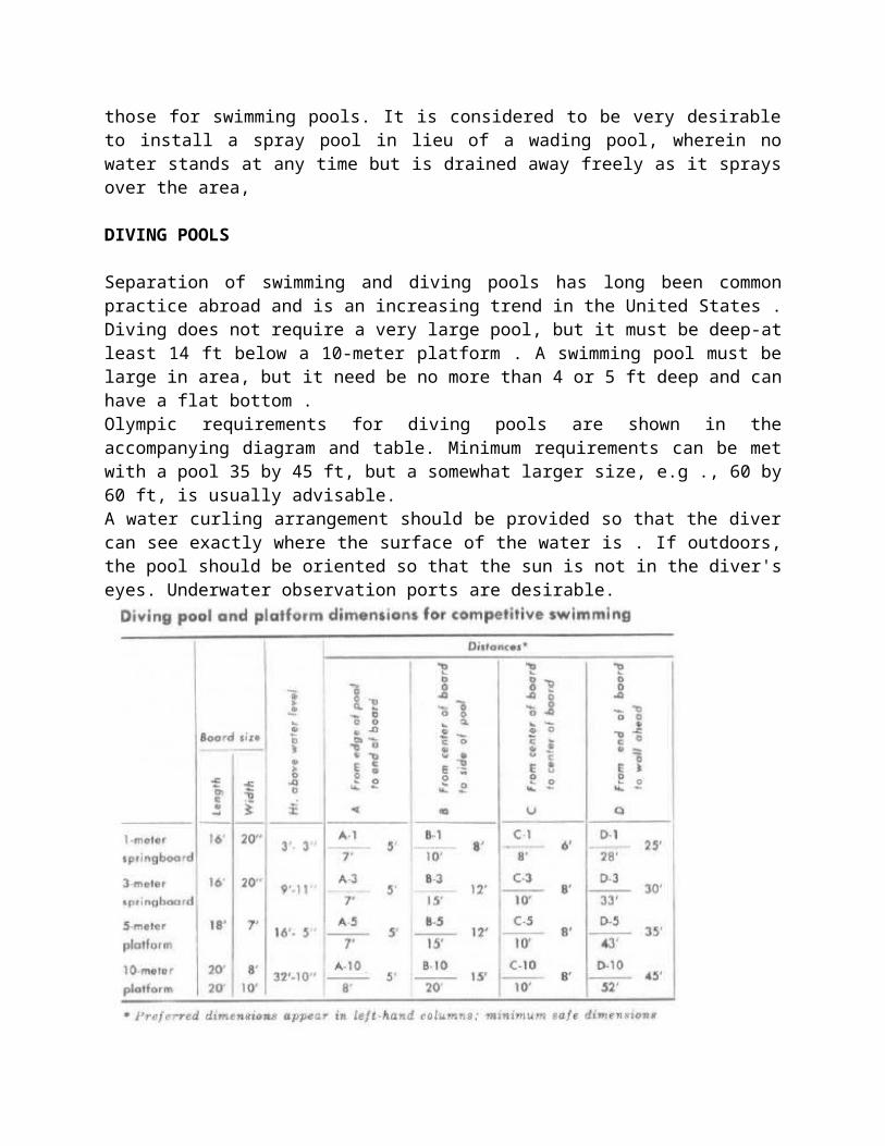
Separation of swimming and diving pools has long been common practice abroad and is an increasing trend in the United States . Diving does not require a very large pool, but it must be deep-at least 14 ft below a 10-meter platform . A swimming pool must be large in area, but it need be no more than 4 or 5 ft deep and can have a flat bottom .Olympic requirements for diving pools are shown in the accompanying diagram and table. Minimum requirements can be met with a pool 35 by 45 ft, but a somewhat larger size, e.g ., 60 by 60 ft, is usually advisable.A water curling arrangement should be provided so that the diver can see exactly where the surface of the water is . If outdoors, the pool should be oriented so that the sun is not in the diver's eyes. Underwater observation ports are desirable.
DESIGN NOTES
Dressing-Locker Room. An average of 14 sq . ft . per pupil in the designed peak load should be provided exclusive of the locker space so there will be adequate dressing area . Check list : sufficient mirrors, built-in drinking fountain and cuspidor in boys' dressing room, tack board. Storage Lockers. Each pupil enrolled should have a storage locker, with an additional 10 per cent to allow for expansion. Recommended sizes, in order of preference are: 7j2 by 12 by 24 in ., 6 by 12 by 36 in ., 7V2 by 12 by 8 in . These were selected as being the minimum size lockers to store ordinary gym costumes and allow free hanging for ventilation.
Dressing Lockers. Lockers large enough to accommodate street clothes should be provided . The number should equal the peak load plus 10 per cent . Lockers 12 by 12 by 72 in . are recommended for secondary schools and 12 by 12 by 54 in . or 12 by 12 by 48 in . for elementary schools.
Shower Room. In the group or gang type shower, the girls should have a number of shower heads equal to These plans show three dressing-locker room arrangements, each with its own particular advantages. Dressing lockers are marked with X's . Plan 1 : storage lockers are grouped in small space for economy in drying uniforms with forced warm air ; some congestion may result from dressing lockers being next to one another.
Plan 2 : distributing dressing lockers over entire area gives each participant ample dressing space. Plan 3 : dressing lockers distributed over entire suite ; units can be installed in any number desired and lend themselves to group dressing method for girls . By constructing walls A, B, C and D, putting a grille to ceiling above locker tiers and installing grille sliding doors at E, each unit becomes a complete dressing room for community use. Walls A, B, C and D can be omitted and gates F added to get some use and permit towel service and toilet units to be installed at points A and D so that the top of the spray will be shoulder height (usually -11 , to S ft .) . on(- to three individual shower booths, 3 bv- 31 2 ft ., should be provided additionally for girls.
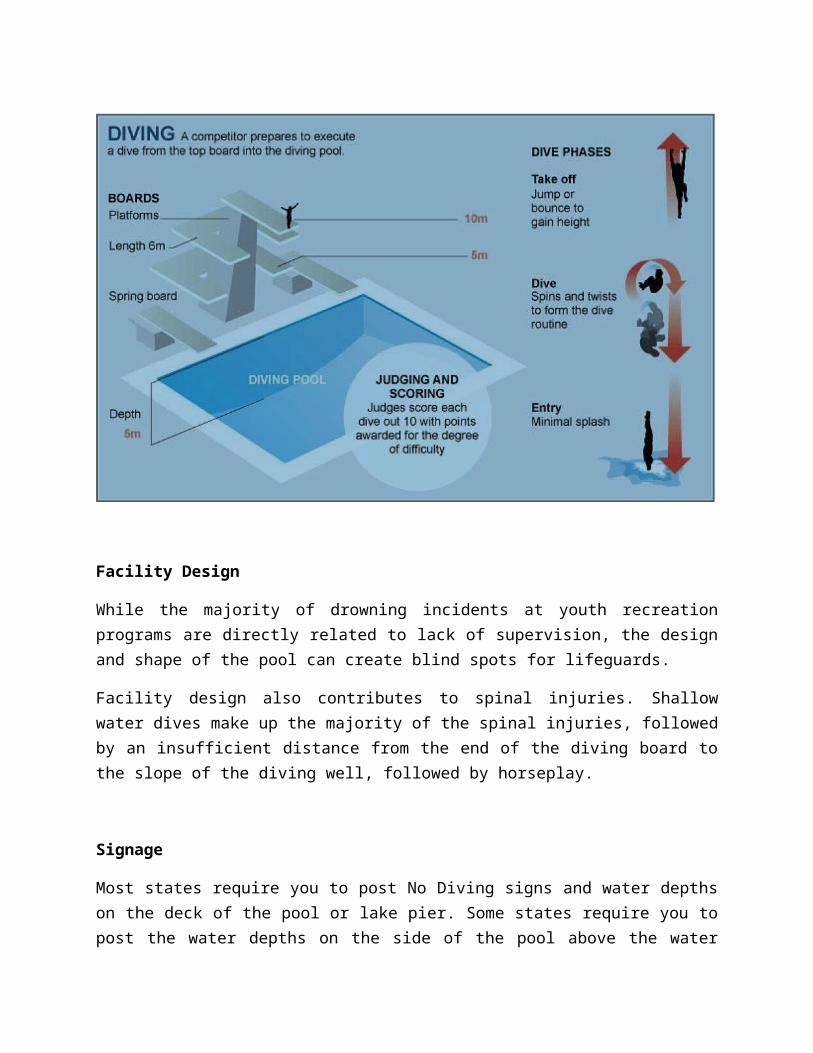
Olympic diving competitions - (there are eight, four for each gender) are strictly airborne and
are held at two heights – a ‘springboard’ dive set at 3m above the water and a ‘platform’ dive, set at 10m.
- Athletes compete individually and in pairs (synchronized diving or ‘synchro’). Individual events consist of a preliminary round, semi-final and final, while the synchro competitions are straight finals.
- Styles of diving include front, back, reverse, inward, twist and armstand, with points awarded according to technique and grace. The more difficult the dive the higher the points it can score if executed well.
- Judges must also take into account starting positions, run-ups, take-offs, flight and entry into water (which should be perpendicular and cause as little splash as possible).
- Each of the seven judges score dives out of 10 and the athlete with the highest total is the winner.
Facility Design
While the majority of drowning incidents at youth recreation programs are directly related to lack of supervision, the design and shape of the pool can create blind spots for lifeguards.
Facility design also contributes to spinal injuries. Shallow water dives make up the majority of the spinal injuries, followed by an insufficient distance from the end of the diving board to the slope of the diving well, followed by horseplay.
Signage
Most states require you to post No Diving signs and water depths on the deck of the pool or lake pier. Some states require you to post the water depths on the side of the pool above the water line. It’s a good risk management practice to do both. Make sure you indicate the unit of measure (feet or meters) for water depth. A pictogram for the No Diving sign
is also a good idea for those who can’t read or don’t read English. All aquatic areas should have signage posted detailing the rules for use. Many states have specific regulations about not only the wording of various rules, but also the specific font size, contrasting colors, and language. All pools and lake swimming areas should have a safety float rope separating the deep end from the shallow area. State regulations vary on the water depth, but most regulations fall around 4 feet 6 inches. There is no magic depth that is safe for swimmers. Lifeguards should be aware that many drowning incidents occur in water 4 to 6 feet deep—the child bounces on his toes with his nose in the air, and the lifeguard fails to recognize that the child is in danger. A key indicator that lifeguards should always watch for is a swimmer’s ability to make forward progress in the water.
Slides
Slides can be a great attraction for aquatic areas. They can also be a huge liability if installed improperly or designed poorly. Markel recommends:
• Slide should exit into at water at least 4 feet deep.
• Slide exit should be horizontal to the water and no more than 18 inches above the water.
• Slide ladders should have handrails.
• Ladders should have a non-skid rubber mat at their base out to a minimum distance of 8 feet, particularly over concrete decks.
• Slide sides should be designed to permit exit at the bottom of the slide only.
• A lifeguard should be specifically dedicated to the slide.
SECTION 1 – GENERAL
Introduction
1. In addition to The Swimming Pool Regulations, 1999, this design/operational standard applies to any swimming pool governed by the regulations that is not a whirlpool.
2. The standards specify minimum prescriptive standards to be followed when establishing, constructing, extending, renovating, or altering a public

swimming pool. However, where supported by sufficient evidence submitted by the proponent, a public health officer may deem an alternative solution as equivalent to the prescriptive requirements provided that:
(a) The alternative solution is capable of performing at least as well as the prescribed standard; and,
(b) The proponent clearly demonstrates and supports how their proposed alternative will achieve the same outcome(s) as the prescribed standard. An appropriate level of evidence, which may include verification of performance by a qualified professional, is required.
Plan Approval
1. An application for a licence shall include a site plan and structural, mechanical, and electrical drawings showing complete construction details and, where applicable, shall include the following:
(a) The street location, the name of the swimming pool facility and the name and address of the owner;
(b) The swimming pool deck elevation relative to the surrounding area;
(c) the location of outlets, drains, overflows, inlets, steps and ladders, diving boards, walk areas, lighting fixtures, equipment, dressing room areas and utilities service lines;
(d) the source of water supply and the method of waste water disposal;
(e) a statement of:
i. pool volumes;
ii. turnover rate;
iii. filtration rate; and,
iv. maximum design load.
(f) the complete detailed specifications and drawing for the construction of the swimming pool, dressing/shower areas, recirculation system, filtration facilities, disinfection equipment and all appurtenances; and,
(g the type of backflow prevention used on the makeup water to avoid cross connection with the public water supply.
2. All plans and specifications for a proposed pool shall be prepared by a professional engineer or architect registered to practice and each drawing is to be duly signed and sealed.
3. The owner shall ensure that the pool and all appurtenances are built in accordance with the plans that were submitted, reviewed by and approved by the public health officer. Any deviation from the approved drawings requires the approval of the public health officer.
Operating Information
Any person who constructs or alters a pool, or dressing room or building used in conjunction with a pool, or who installs any equipment in a pool, dressing room or building shall:
(a) Furnish the operator with complete operating instructions and drawings; and,
(b) in the case of the pool equipment, attach a tag to every drain, valve or other fitting to indicate its function.
Licence Required
A pool is subject to inspection prior to the issuance of a licence and at any other time that a public health officer considers necessary or desirable.
Chemical Handler Certification
No person shall handle, store or use pool chemicals
(a) without successfully completing a swimming pool operator's course that is recognized by the public health officer; or,
(b) unless they are acting under the direct supervision of a person who has successfully completing a swimming pool operator's course that is recognized by the public health officer.
Lifeguard Certification
Where lifeguards or supervisors are required in the safety plan, pool operators shall maintain proof of certification of all lifeguards and supervisory staff employed at the pool and make these records available to a public health officer upon request.
SECTION 2 - POOL CONSTRUCTION
General
Application of Standard
This section (2.1) applies to wave pools, paddling pools, water flume slide facilities and other swimming pools but not to whirlpools.
Materials
1. Components which come into contact with the water intended for use in swimming pools shall be of a material type that is non-toxic to humans, impervious and enduring.
2. The materials to be used in and around a water theme facility (paddling pool, wave pool or water slide facility) or swimming pool shall be of a type such that the operational strength of the entire assembly and each of its components are not adversely affected by exposure to rain, snow, ice, sunlight, local normal temperature extremes, local wind pressures, expected local air pollution products and the mechanical, electrical and chemical environment in and around the water theme facility or pool.
3. Materials selected for components and accessories used in and around the facilities shall be of a type that all parts with external surfaces and edges, that may come in contact with the user, are assembled, arranged, and finished so that they will not constitute a cutting, pinching, puncturing, or abrasion hazard in casual contact and intended use.
Basin Design
1. The pool basin shall be a watertight structure that has a smooth and easily cleanable surface (excluding structural joints).
2. The sides and bottom of the pool basin shall be light in colour. 3. The radius of curvature between the pool wall and the pool floor shall
not exceed 150 millimetres where the water depth is less than 1.5 metres.
4. All side and end walls shall be vertical. 5. The floor of the pool basin shall have a slope towards the main
drain(s).
6. The slope of the bottom of the pool where the water is less than 1.5 metres deep shall not be greater than 1:15. This slope shall be uniform.
Handhold
1. Handholds shall be provided:
(a) along the length of each wall of the pool; and,
(b) placed not more than 230 millimetres above the normal water line.
2.Where an overflow channel is installed in a pool, it may be designed to serve as a handhold. No handhold shall be extended above the top of the wall of the pool on which it is installed.
Play Equipment
Before any play equipment is installed, constructed or used in any swimming pool, approval of design and location shall be obtained from a public health officer. Wherever play equipment is installed, specific safety instructions shall be given to all users through the means of posted instructions placed on the equipment.
POOL SLIDES
General
1. All children’s activity, drop and other slides used at pools shall be specifically designed and intended for use with a pool, and for the specific application. Slides shall be permitted only where supervision of the slide is incorporated into the safety plan.
2. The construction, dimensions and mechanical attachments of the components of a water slide shall ensure that the surface of the water slide is continuous and smooth throughout its length.
3. Wall thickness of a water slide shall be designed so that the continuous and combined action of hydrostatic, dynamic, and static loads and normal environmental deterioration do not cause structural failure which could result in injury, or continually require repair which would weaken the strength of the original structure.
4. Water slides shall only be installed where the public health officer is satisfied that joints, materials, tunnels, turns, ladders, exit areas, the receiving pool and other associated items of a water slide shall provide a safe environment for the swimmer.
5. The public health officer may approve deviations from the standard with respect to slides when:
(a) the standard does not adequately address the specific designs;
(b) sufficient information, in the opinion of the public health officer, for evaluating the proposal is submitted; and,
(c) in the opinion of the public health officer, the operation of the proposed slide is safe.
Children Activity Slides
Children’s activity slides are small slides with a low exit velocity designed by the manufacturer for use by small children at pools. They shall be designated by the manufacturer for use in 61 cm (24 inches) or less of water and installed accordingly.
Drop Slides
1. Drop slides are slides which discharge into a pool with a drop of more than 5 centimeters (2 inches) to the water surface:
(a) Slide entry areas shall be designated so the rider is able to properly enter and position him or her self before sliding down the chute. This area shall be a small platform or a less sloped portion of the chute with well placed assist bars.
(b) Drop slides shall have handrails on both sides of the ladder and steps. Platforms and landings shall have a 110 centimetres (42 inches) high guard rails, with at least one intermediate-height rail.
(c) There shall be a drop slide landing area extending 1.5 metres (5 feet) on either side on the center line of the slide and from the backwall to 6.1 metres (20 feet) in front of the slide terminus. This area shall not infringe on the required landing areas for other drop slides, water flume slides, or diving equipment.
(d) The drop slide landing area shall be separated from the rest of the pool in a manner approved by the public health officer. A slide mounted in a separate diving area may be allowed to use the diving area separation as long as access to the diving well is restricted to patrons using slide and diving equipment.

(e) The terminus of the chute shall extend beyond the pool wall, and be so oriented that the safety area in front of the slide does not interfere with the safety area of another slide or other pool equipment.
(f) The maximum angle of the slide runway at the exit shall be between zero degrees and 11 degrees, measured downward from horizontal.
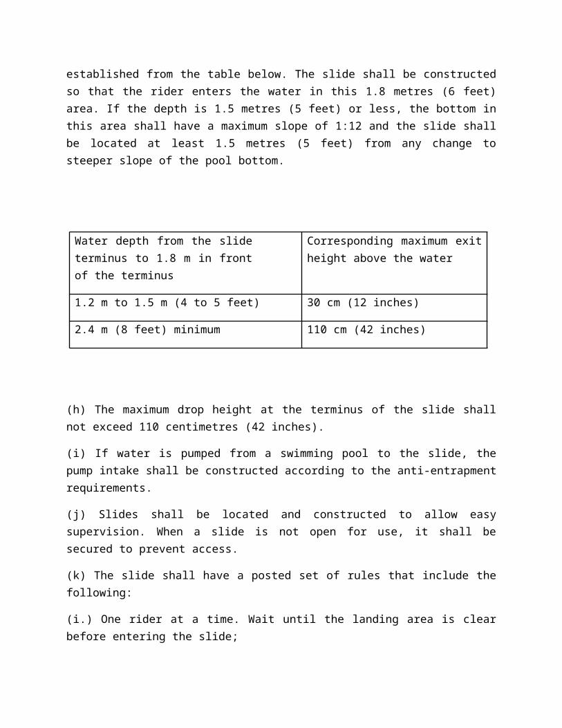
(g) The area in front of the slide terminus outward to 1.8 metres (6 feet) in front of the slide terminus shall have a depth as established from the table below. The slide shall be constructed so that the rider enters the water in this 1.8 metres (6 feet) area. If the depth is 1.5 metres (5 feet) or less, the bottom in this area shall have a maximum slope of 1:12 and the slide shall be located at least 1.5 metres (5 feet) from any change to steeper slope of the pool bottom.
Water depth from the slide terminus to 1.8 m in front of the terminus
Corresponding maximum exit height above the water
1.2 m to 1.5 m (4 to 5 feet) 30 cm (12 inches)
2.4 m (8 feet) minimum 110 cm (42 inches)
(h) The maximum drop height at the terminus of the slide shall not exceed 110 centimetres (42 inches).
(i) If water is pumped from a swimming pool to the slide, the pump intake shall be constructed according to the anti-entrapment requirements.
(j) Slides shall be located and constructed to allow easy supervision. When a slide is not open for use, it shall be secured to prevent access.
(k) The slide shall have a posted set of rules that include the following:
(i.) One rider at a time. Wait until the landing area is clear before entering the slide;

(ii.) Slide in a sitting position or on the back only;
(iii.) Do not attempt to stop in the slide;
(iv.) Leave plunge area immediately;
(v.) Warning Water Depth is _____ metres (____ feet); and,
(vi.) Non-swimmers not permitted (if over 1.5 metres deep).
Flume Water Slides
A water flume slide consists of one or more flumes entering a plunge pool or dedicated plunge area of a multiple use pool at or near the water level. The requirements for water flume slides are listed separately in this standard under the heading of “Water Flume Slide”.
Stairs and Ladders
Stairs or ladders shall be installed:
(a) at the shallow portion of the pool where the vertical distance from the bottom of the pool to the deck or top of the wall is more than 600 millimetres; and,
(b) where a pool is more than 9 metres wide, at each side of the pool.
- A ramp or step shall be continuous in nature and without spaces or gaps between the edge or side, of this ramp or step and the wall of the pool.
- Recessed steps with grab-rails may be used in place of ladders.
- Stairs shall be sloped towards the pool to prevent an accumulation of settleable solids.
Recommendation
The stairs should be finished in a manner that will contrast with the pool.
- Treads on steps of ladders and stairs shall not be less than 76 millimetres deep over their full width and have non-slip surfaces. Ladders shall be corrosion- resistant and are to be rigidly installed.
- There shall be a clearance of not more than 150 millimetres between a ladder and the wall of the pool on which the ladder is installed.
- All ladders shall be removable.
Deck Areas
1. A deck area shall surround the entire pool.
2. The deck area shall not be less than 1.8 metres in width and provide not less than 0.9 metre of clear passage behind a diving board or any slide or other piece of play equipment and its supporting structure.
3. In pools where the pool floor forms part of the deck (e.g., zero depth or zero beach type pools), the deck shall have a slope away from the pool for a distance of at least 0.6 metre with positive drainage to the recirculation drains. In this area the width of the deck drained to the recirculation drains shall not be greater than 1.8 metres.
4. For pools where recessed gutters or skimmers are used, the deck shall be sloped away from the pool and drained to waste.
Recommendation
A slope of 1:40 is recommended for the deck.
5. All walks, decks and terraces surrounding pools shall be uniformly sloped to drains or points at which the water will have a free unobstructed flow to points of collection.
Recommendation
Deck drains shall be free from obstruction (e.g., benches, lockers) to permit ease of cleaning.
6. The number of deck drains shall be calculated at a rate of 20 square metres of deck surface per drain.
7. Deck surfaces shall be non-slip when wet, sufficiently smooth to facilitate disinfection and shall not create discomfort to bare feet.
8. Where brushed concrete finishes on deck surfaces are used, brushing shall be done toward the drains.
9. Deck surfaces shall not be painted.
Recommendation
The colour and finish of deck surfaces should be selected so as to minimize glare from overhead lighting.
10. Hot water shall be available from the hose bibs for deck cleaning and disinfection.
Recommendation
Hose bibs of not less than 19 millimetres diameter should be located in such a manner that all parts of the pool deck area may be reached with a 30 metre hose.
LIGHTING
1. General Design Considerations:
(a) The impact of glare from artificial and natural light sources on supervisors and lifeguards shall be considered during the design of swimming pool and water theme facilities.
(b) Lights shall be located so that bulbs can be replaced when the pool is in use.
(c) Lights shall be shielded or shatter-proof.
(d) Light shields shall be shatter-proof.
2. Underwater Lighting:
Where underwater lighting is to be used in a swimming pool or water theme facility, the total lamp lumens shall be not less than:
(a) 650 multiplied by the area in square metres of the water surface for an outdoor swimming pool or water theme facility; or,
(b) 1100 multiplied by the area in square metres of the water surface for an indoor swimming pool or water theme facility.
3. Pool Area Lighting:
An indoor pool or an outdoor pool where night swimming is permitted shall:
(a) Where underwater lighting complying to section 2 is used, provide area lighting designed to ensure a minimum of 215 lux at the deck level for all the deck areas that is directed towards the deck areas and away from the pool surface; or,
(b) Where underwater lighting complying to section 2 is not used, provide area lighting designed to ensure a minimum of 215 lux at the deck level for all the deck areas and at the pool water surface.
4. General Area Lighting:
(a) Lighting with a minimum of 215 lux at floor level shall be provided in pool dressing rooms and any other area of the facility used by swimmers.
5. Emergency Lighting:
(a) All indoor pools and outdoor pools, with lighting for night use, shall have independent emergency lighting systems designed to provide a minimum of 10 lux at deck level that automatically operate whenever the main lighting system fails.
(b) The system shall be constructed and arranged to ensure that the pool, deck, dressing rooms, washroom facilities and exit passages are safely lit to facilitate prompt evacuation.
Drinking Fountains
At least one drinking fountain shall be provided.
Recommendation
Drinking fountains should be recessed; accessible to all swimmers and located away from the deep end of the swimming pool.
Equipment Room
1. Doors to the equipment and mechanical room shall be locked to prevent unauthorized entry.
2. The equipment and mechanical room or rooms shall be adequately lighted, heated and ventilated.
3. The equipment and mechanical room shall have a floor drain and the floor should be sloped to create positive drainage.
4. Chemicals shall not be stored in an area that provides access to other areas or that is near heating equipment.
Recommendation
Chemicals should be stored on platforms raised sufficiently off the floor to prevent damage by water.
Dressing Room Facilities
1. Dressing rooms shall be well-lighted, drained, ventilated and of good construction with impervious materials, finished in light colours and so developed and planned that good sanitation can be maintained throughout the building at all times.
2. Unless otherwise approved by the Public Health Officer, the size of the dressing room area shall be based on:
(a) maximum swimmer load with 0.5 square metres of floor space for each swimmer; or,
(b) where swimmer load is determined to be 50 swimmers or less, dressing rooms for each sex shall have a minimum floor space of not less than 12.5 square metres.
3. No steps shall be installed in the interior of the dressing room areas nor between the shower area and adjoining pool deck areas. Should it be necessary that the shower area be at a different elevation from the pool deck, a ramp shall be provided, constructed with a non-slip surface and a slope not exceeding 1:12.
4. All partitions and walls in the dressing room areas shall be of durable material and shall be so designed that a space of at least 150 millimetres is provided between the partitions and floor to permit thorough cleaning of the walls and floor areas with hoses and brooms.
5. Floors shall be of a smooth but non-slip finish, impervious to moisture with no open cracks or joints. All corners should be rounded and have coving of wall to floor for ease of cleaning.
6. Floors shall be so drained as to prevent pooling of water. A slope of not less than 1:40 towards the closest drain shall be provided.
7. If lockers are provided, they shall be constructed of a durable rust resistant material.
8. At least one 19 millimetre hose bib per dressing room shall be provided for flushing down and disinfecting the dressing room and shower interior. The hose bibs shall be supplied with hot water.
9. Separate dressing rooms for male and female patrons shall be provided where the pool will be used simultaneously by both sexes.
10. Where a pool is not used simultaneously by male and female patrons, at least one dressing room shall be provided.
11. In the case of an operator who has not complied with subsection (9) or (10), the requirements may be waived if a public health officer is satisfied that:
(a) a dressing room provided for the use of persons engaged in some recreational activity, other than swimming, is conveniently located and available for use by persons using the pool; or,
(b) the use of the pool is restricted to the owner or occupant and the family and guests of the owner or occupant of a building that contains more than two dwelling units; or a dwelling unit that is located in an apartment block, hotel, motel, trailer court or institutional camp.
12. Dressing rooms shall be equipped with garbage receptacles.
13. The doorway to a dressing room shall be:
(a) separated from a doorway to any other dressing room; and,
(b) located at the shallow end of a swimming pool, except where a barricade of a type approved by a public health officer is provided and is designed so that traffic to the pool is directed to the shallow end.
Washroom Facilities
1. Unless otherwise approved by the public health officer, washroom facilities for each sex shall be provided at all pools.
2. The number of required fixtures shall be calculated on the basis that 50% of the occupants will be male and 50% of the occupants female, or as determined from experience or proposed use.
3. The minimum number of water closets for each sex shall be based on maximum swimmer load. (Note: Gallery spectator area washroom requirements are governed by The Uniform Building Accessibility Standards Act and Regulations – National Building Code)
4. For each 50 males or fraction thereof, there shall be 1 water closet or 1 urinal and 1 handbasin. As a minimum, there shall be 1 water closet, 1 urinal and 1 handbasin.
5. Where more than 2 water closets are required, urinals may be substituted for 2/3 of the required number of water closets and may be counted as water closets.
6. For each 50 females or fraction thereof, there shall be 1 water closet and 1 handbasin.
7. Access to the washroom for gallery spectators shall not require a spectator to pass through the dressing rooms.
8. The lower 1.5 metres of the wall in the water closet and hand basin area shall be impervious.
9. Toilet tissue in suitable dispensers shall be provided at each water closet.
10. Soap dispensers with either liquid or powdered soap shall be provided at each hand basin. Dispensers shall be all-metal or plastic type and contain no glass.
11. Paper or equivalent towels in suitable dispensers or hot air dryers shall be provided near the hand basins.
12. Each washroom shall be equipped with garbage receptacles. In addition, individual garbage receptacles shall be located in female water closets.
Shower Facilities
1. The number of showers provided in both male and female dressing rooms shall be one for each 40 users or part thereof calculated on the maximum swimmer load, except that the minimum number of showers in each dressing room shall be two.
2. Each shower facility shall be equipped with a thermostatic mixing valve that is capable of providing a sufficient supply of hot water to each shower head at a temperature of not more than 40C.
3. Floor drains shall be so designed that waste water from shower heads will not pass over the floor area of another shower.
Recommendation
One drain per shower head is recommended.
4. Soap dispensers with either liquid or powdered soap shall be provided between each pair of shower heads. Dispensers shall be all-metal or plastic type and contain no glass.
5. All showers shall be located in such a manner that the swimmer shall pass by or through the shower area before entering the pool areas
6. Except for the purpose of lighting, no person is to install or bring any glass into the portion of the dressing room which contains shower heads.
Pool Area
1. Except where grassed areas are provided, the pool area is not considered to form part of the deck shall be finished with a hard, impervious, non-slip material.
Recommendation
Facilities should be provided for proper cleansing of swimmers before re-entering the pool from these grassed areas.
Recommendation
Access to the pool deck should be located at the shallow end of the pool.
2. Garbage receptacles shall be provided in the pool area.
Gallery
1. Where a gallery for spectators is provided at a pool, the owner shall ensure that the entrance to and exit from the gallery does not require a spectator to pass through the dressing room or across the deck of the pool.
2. No gallery shall overhang any portion of the water area in the pool.
3.The vertical distance between the deck of the pool and the lowest portion of a gallery or overhead obstruction that overhangs the deck shall be at least 2.5 metres, unless otherwise approved by a public health officer.
Food Concessions
1. Food and/or beverages shall only be consumed in an area set aside for that purpose.

2. No glass containers or any other materials, which may constitute a hazard to swimmers, shall be used.
Ventilation
All indoor pool facilities shall be provided with an adequate ventilation system.
Fencing/Walls
1. The pool shall be completely surrounded by a fence or wall that:
(a) is at least 1.8 metres in height;
(b) is designed and constructed to discourage unauthorized entry; and,
(c) has a gate or door equipped with panic hardware, for use in the event of an emergency, that is located away from both the chlorine room, if present, and the deep end of the pool.
Swimming Pool
Application of Standard
This section (2.2) applies only to all swimming pools that are not wave pools, paddling pools, whirlpools or water flume slide facilities.
Basin Design
The area of the pool designated as a deep area shall extend vertically downward for a minimum distance of 1680 millimetres; and the shallow area of the pool shall extend vertically downward for a minimum distance of 790 millimetres.
Diving Boards and Platforms
1. Diving boards or platforms provided shall be rigidly constructed and properly anchored at the base with sufficient bracing to ensure stability under the heaviest possible load. Manufacturer's specifications regarding installation and usage of diving boards or platforms shall be adhered to.
2. Design of diving boards and platforms and their corresponding depths and clearances shall conform to Appendix B.
3. Diving boards and platforms in excess of 3 metres in height shall comply with technical specifications for diving facilities found within the most current Federation Internationale de Natation Amateur (FINA) - Standard.
Stairs and Ladders
1. In addition to the general requirements, stairs or ladders shall be installed at the deep portion of the pool.
2. The stairs or ladders in the deep end of the swimming pool shall be placed to direct the swimmer away from the diving boards and diving area.
Depth Markings
1. The depth of water shall be plainly marked at the point of minimum depth; 1.2 metres depth; and at the points of break between gentle and steep bottom slopes. The words "deep area" and "shallow area" shall be clearly marked in letters at least 100 millimetres high of a colour contrasting with the background at appropriate locations.
2. Depth markings shall indicate the depth on the deck in legible numerals at least 100 millimetres high of a colour contrasting with the background.
Recommendation
Wherever possible, depth markings should also be located on the wall of the pool basin above the operating water level.
3. Depth markings shall be placed on both sides and both ends of a swimming pool. The distance between markings is not to exceed 7.6 metres. ]
4. At the 1.2 metre mark and at any point in the pool where the slope is greater than 1:12, the pool shall be equipped with apparatus to house a safety line with a minimum diameter of 19 millimetres. This safety line shall be equipped with floats.
Recommendation
All lane divider ropes used in swimming pools should be removed when the swimming pool is not in use for more than 1 hour, to permit proper circulation.
5. The position of every safety line or life line shall be marked by coloured buoys attached to the safety line or lifeline at intervals of not more than 1.5 metres.
Paddling Pool
Application of Standard
This section (2.3) applies only to all paddling pools but not wave pools, whirlpools, water flume slide facilities or other non-paddling pool swimming pools.
Basin Design
1. Paddling pools shall:
(a) be completely free of obstructions which may be hazardous to children; and,
(b) have a floor with a maximum slope of 1:15 and a minimum of 1:50, unless otherwise approved by a public health officer.
Depth Markings
1. Depth of water markings shall be plainly marked and conspicuously posted at a minimum of two locations and shall:
(a) indicate the maximum depth of water;
(b) be positioned to be read by persons using the pool;
(c) be on the deck within 460 millimetres of the water edge in legible numerals/letters 100 millimetres high of a colour contrasting with the background; and,
(d) not create a hazard.
Water Flume Slide
Application of Standard
This section (2.4) applies only to all water flume slides but not wave pools, paddling pools, or whirlpools.
General
1. Water flume slides require special consultation with the public health officer for consideration of design variations and areas where potential problems may exist.
2. Water flume slides often make use of a multi-use pool. If a multi-use pool is proposed, Section 2.2, 3.2, 4.2 and 5.2 should apply. Requirements for swimming pools may be modified or waived for water flume slides at the discretion of the public health officer.
3. All water flume slides used at pools shall be specifically designed and intended for use with a pool, and for the specific application. Slides shall be permitted only where supervision of the slide is considered in the safety plan.
4. The construction, dimensions and mechanical attachments of the components of a water flume slide shall ensure that the surface of the water slide flume is continuous and smooth throughout its length.
5. Wall thickness of a water slide flume shall be designed so that the continuous and combined action of hydrostatic, dynamic, and static loads and normal environmental deterioration do not cause structural failure which could result in injury, or continually require repair which would weaken the strength of the original structure.
6. Water flume slides shall only be installed where the public health officer is satisfied that joints, materials, tunnels, turns, ladders, exit areas, the receiving pool and other associated items of a water slide shall provide a safe environment for the swimmer.
7. The public health officer may approve deviations from the standard with respect to slides when:
(a) the standard does not adequately address the specific designs;
(b) sufficient information, in the opinion of the public health officer, for evaluating the proposal is submitted; and,
(c) in the opinion of the public health officer, the operation of the proposed slide is safe.
Depth Markings
1. Depth of water markings shall be plainly marked and conspicuously posted at a minimum of two locations and shall:
(a) indicate the maximum depth of water;
(b) be positioned to be read by persons using the slide;
(c) be on the deck within 460 millimetres of the water edge in legible numerals/letters 100 millimetres high of a colour contrasting with the background; and,
(d) not create a hazard.
Flume Exit
1. Flume exit sections shall be designed to assure safe exit speeds, angles, and stopping distances.
2. A flume shall be perpendicular to the plunge pool wall for a distance of at least 3 metres (10 feet) from the exit of the flume.
3. The distance between the side of a flume exit and a receiving poolside wall shall be at least 1.5 metres.
4. The distance between sides of adjacent flume terminuses shall be at least 2 metres.
5. The unobstructed distance between a flume exit and the opposite side of the receiving pool shall be at least 6 metres.
6. In the case of high-speed slides, special provisions shall be made in flume exit design, pool depth, and pool width (measured from flume exit) to safely accommodate slides specifically designed with greater slopes or other special features which allow an unusually rapid descent.
7. Multiple-exit slides shall have parallel exits or be constructed so that their centre lines do not intersect for a distance of at least 6 metres from the exits of each flume. If slides with nonparallel exits discharge swimmers at a high speed, the centre lines shall not intersect for at least 9 metres.
8. Unless otherwise approved by a public health officer, flumes shall terminate either at a depth of at least 150 millimetres below the receiving pool's operating water level or no more than 50 millimetres above the water surface. The flume shall not exceed a 1:10 slope for a distance of at least 3 metres from its exit end.

Plunge Pools
1. Unless otherwise approved by a public health officer, the receiving pool water depth at the end of the flume shall be between 1 meter and 1.2 meters.
Recommendation
This depth should be maintained in front of the flume for a distance of at least 6 meters, from which point the receiving pool floor may have a constant slope upward to the minimum water depth. These slopes should be no more than 1:10. The maximum depth within 1.5 meters of the slide flume median is to be no more than 1.2 meters.
2. If special exit systems that assure safe exit from the flume and safe entry to the receiving pool are used, the 1 meter minimum depth and minimum maintenance distance for this depth may be modified or waived by the public health officer.
3. The plunge area in a multi-use pool shall be designated by float ropes, and each area shall have ladders, steps, or stairs for egress.
General Safety
1. All curves, turns, and tunnels within the slide flume shall be designed so that body impact with the walls of the flume or ceiling of a tunnel does not present a hazard and users do not become airborne.
2. The slide flume shall be banked to keep the slider's body safely inside the flume or curve.
3. In sections of the elevated flumes where, contrary to intended use, a slider may stop, there shall be safety walls or other provisions to keep the slider from falling out of the flume.
Walkways & Steps
1. Walkways and steps shall be:
(a) well drained;
(b) non-slippery;
(c) separated from the flume by a physical barrier; and,
(d) set back far enough from the operating flume so that users cannot contact it on the way down.
2. A 1.2 metre minimum width walkway or steps shall be provided between the plunge pool deck and the steps leading to the top of the flume.
Wave Pool
Application of Standard
1. This section (2.5) applies only to all wave pools but not paddling pools, whirlpools, water flume slide facilities or other non-wave pool swimming pools.
Depth Markings
1. Depth of water markings shall be plainly marked:
(a) at a point of minimum depth, 1.2 metres depth, and at the points of break between gentle and steep bottom slopes. The words "deep area" and "shallow area" are to be clearly marked in letters at least 100 millimetres high of a colour contrasting with the background at appropriate locations; and,
(b) on the deck within 460 millimetres of the water edge and are to indicate the depth of water in legible numerals at least 100 millimetres high of a colour contrasting with the background.
Recommendation
Whenever possible, depth markings should also be located on the wall of the pool basin above the operating water level.
2. Depth of water markings shall be placed on both sides and both ends of a wave pool, the distance between markings is not to exceed 7.6 metres.
3. All depth of water markings shall be placed in a manner that will not create a hazard.
Handholds
1. In the case of pools designed to be operated as both a wave pool and swimming pool, handholds shall be provided along the length of each wall of the pool and installed so that they are not more than 230 millimetres above the water line when the wave pool is not in operation.
2. If installed, handhold railings shall be mounted to the pool basin wall in a fashion that will not cause swimmer entrapment problems.
Stairs and Ladders
1. In addition to the general requirements, stairs or ladders shall be installed at the deep portion of the pool.
2. The stairs or ladders in the deep end of the swimming pool shall be placed to direct the swimmer away from the diving boards and diving area.
Safety Line
1. In the case of pools designed to be used as both a wave pool and swimming pool, safety line anchors shall be installed in the pool basin walls at the 1.2 metre depth of water mark and at the start point of where the pool basin slope is greater than 1:12.
2. Where a wave pool is used as a swimming pool, a safety line (minimum diameter of 19 millimetres) with floats shall be attached to the anchors stated in sentence (1) during the operation of the swimming pool.
POOL RECIRCULATION SYSTEM
General:
Application of Standard
This section (3.1) applies to wave pools, paddling pools, water flume slide facilities and other swimming pools but not to whirlpools.
Continuous Operation
1. Except for stoppage for maintenance, repairs or backwashing of filters or as authorized by the regulations, the recirculation systems and chemical feeders shall operate continuously, regardless of the duration of actual use of the pool each day.
Piping System
1. The piping system shall be designed to:
(a) circulate the pool water through the treatment equipment;
(b) allow each filter to be individually backwashed;
(c) drain backwashed water to waste;
(d) empty the pool;
(e) drain or blow out the entire system;
(f) permit circulation of water in a closed system between a diatomaceous earth filter and pump during the precoat operation to avoid diatomaceous earth entering the pool;
(g) allow for adequate, accessible and easily serviceable valves that permit flexible operation of the filtration equipment;
(h) allow for the determination and isolation of leaks in buried lines; and,
(i) provide for chemical treatment and heating of the water.
2. The recirculation piping and fittings shall be of a non-toxic material, resistant to corrosion, and able to withstand operating pressures.
Outlets
1. Water outlets shall be designed so that each pumping system in the pool (filter system(s) or jet system(s) if so equipped) complies with section 3.1.5 Anti Entrapment.
2. One or more drain outlets shall be provided at the lowest point of the pool floor. The total orifice area of all the pool drain outlets shall be at least four times the cross-sectional area of the main pool drain line and be sized to accommodate the main drain recirculation rate.
3. The main drain piping shall be sized to accommodate 100% of the recirculated water.
4. All suction drain covers shall:
(a) conform to ASME A112.19.8;
(b) have a flow through the drain grate which does not exceed 0.45 m/s (1.5 fps); and,
(c) a minimum sump depth which is 1.5 times the diameter of the inlet pipe.
3. The drain covers shall present no sharp edges to the adjacent surfaces. Each drain cover shall be so secured that the removal requires the use of a tool.

Anti Entrapment
1. New swimming pools and water theme facilities shall be designed to include one of the following in order to prevent the entrapment of patrons in the drains and recirculation equipment:
(a) a minimum of two hydraulically balanced outlets per pump that are inserted into the system so that no outlet can be cut out of the suction line by a valve or other means and with the outermost outlet centers at least 920 mm apart;
(b) one or more unblockable drain;
(c) no main drain; or,
(d) another solution acceptable to the public health officer.
Recommendation:
Additional Barriers recommended such as an unblockable drain, a suction limiting vent system, a gravity drainage system that utilizes a vented collector tank or an automatic pump shut-off are recommended.
Existing pools, when renovated, should consider upgrading to mitigate the risks associated with a single main drain.
2. If a drain cover or grate is cracked, broken or missing, the pumps shall be immediately shut down and the pool closed until the grate or cover replaced.
3. For the purposes of accessing the effectiveness of an anti-entrapment device, the public health officer may require an engineer’s report.
4. The owner/operator shall ensure that all anti-entrapment devices are properly installed and in good working order and be able to demonstrate that no entrapment or entrapment risk is present.
5. The on/off switch for all circulation pumps shall be clearly marked, and labelled as well as accessible and known to pool staff.
Overflow Structures
Overflow structures may be either perimeter overflow channels or skimmers or both.
Skimmers
1. Skimmers shall be:
(a) constructed of corrosion resistant materials and be fully recessed behind the face of the pool wall;
(b) accessible through the deck;
(c) conform to NSF 50 Equipment for Swimming Pools, Spas, Hot Tubs and Other Recreational Water Facilities;
(d) equipped with an easily removable and cleanable basket or screen through which all the overflow water shall pass and which is capable of trapping solids larger than 3 millimetres in dimension;
(e) equipped with a valve or other device for regulating flow so that uniform skimming action can be achieved; and,
(f) designed to handle a minimum flow of 2.3 litres per second.
Perimeter Overflow Channels
1. Where overflow channels are provided, the channel shall:
(a) extend completely around the pool;
(b) be adequately sized to prevent water entering the channel from washing back into the pool;
(c) be designed so that the dimensions minimize the danger of swimmer entrapment;
(d) be adequately sized and sloped to provide rapid drainage to drains which are not less than 50 millimetres in diameter and spaced not more than 4.5 metres apart; and,
(e) be of a capacity sufficient to carry 125% of the designed recirculation rate.
Strainer
The circulation system, when receiving water directly from the pool, shall Include a strainer to prevent hair, lint and other materials from reaching the pump and/or filters.
Recommendation:
Two corrosion-resistant strainer baskets should be provided.
Gauges
Gauges shall be installed in all piping systems to measure the pressure drop across pressure type filter systems, suction pressure on vacuum filter systems and on both sides of circulation pumps for checking their operational performance.
Filtration
1. Unless otherwise approved by a public health officer, a filter system shall be of a sand, anthracite, diatomaceous earth or cartridge type.
2. A filter system shall operate continuously at the designed rate of flow for that filter system.
Rate of Flow Indicators
1. A rate of flow indicator shall be provided in the piping system to indicate the rate of pool water circulation.
2. Where a single treatment plant serves two or more separate pools, provision shall be made for measuring the flow into or from each pool.
Pool Heat
1. Valved piping shall be provided for regulating flow through the heater and for bypassing or isolating the heater.
2. One or more approved thermometer(s) shall be in use for determining water temperature.
3. The water in any swimming pool shall not be artificially heated to a temperature above 30ºC unless permission to do so has been granted by a public health officer.
Chemical Feeders
Adjustable output rate chemical feeding equipment shall conform to the Joint National Swimming Pool Institute - National Sanitation Foundation Standard relating to adjustable output rate chemical feeding equipment for pools, or as required by a public health officer.
Disinfection Equipment
1. All pools shall be equipped with equipment to provide continuous disinfection when in use, at a dosage necessary to meet minimum residual requirements outlined in The Swimming Pool Regulations, 1999 and to maintain the pool water in a bacteriologically safe condition at all times.
2. The disinfection equipment shall be maintained in satisfactory working order, and spare parts essential to immediate safety should be on hand for immediate use.
3. The disinfection equipment shall include some positive feature to prevent siphoning when installed above the pool.
4. Where gaseous chlorine equipment is used, requirements are outlined in the Occupational Health and Safety Regulations. Contact the Ministry of Labour Relations and Workplace Safety for details.
Cross-Connections
No piping arrangement under any condition shall permit sewage or waste water to enter the recirculation system, or permit water from the recirculation system or pool to enter a potable water supply.
Vacuum Cleaning Equipment
1. All pools shall be provided with vacuum cleaning equipment which will remove sediment in the pool basin.
Recommendation:
Fixed pipe connections from the vacuum cleaning equipment fittings to the pump should be free of air pockets and slope downwards from the pool to the pump.
2. Skimmer systems or portable pump vacuum cleaning equipment are permissible alternatives.
Inlets
1. Inlets shall be constructed of non-corrosive material, and sized to prevent an entrapment hazard.
2. The minimum number of adjustable inlets, providing uniform circulation of water and uniform distribution of disinfectant, shall be:
(a) based on either one inlet per 55 square metres (600 square feet) or portion thereof pool area, or one inlet per 57,000 litres (15,000 gallons), whichever is greater. In any case a minimum of four inlets are required;
(b) placed not more than 6 metres (20 feet) apart around the entire perimeter, with one inlet within 1.5 metres (5 feet) of each corner of the pool and one in each recessed step area;
(c) submerged not less than 0.6 metres (2 feet). If the pool water depth is less than 0.6 metres (2 feet), the inlet fittings shall be placed as near to the pool floor as possible. In water greater than 1.5 metres (5 feet) deep they shall alternate between one third of the depth from the top of the water and a depth of one third from the bottom;
(d) supplied with bottom inlets for pools over 18 metres (60 feet) in width. Bottom inlets shall be uniformly spaced with a separation distance of no greater than 6 metres (20 feet) and with rows of inlets within 4.5 metres (15 feet) of each side wall. The floor inlets shall be flush with the floor; and,
(e) subject to having a dye test (crystal violet or equivalent) performed to determine and adjust the recirculation pattern.
Swimming Pool
Application of Standard
This section (3.2) applies only to all swimming pools that are not wave pools, paddling pools, whirlpools or water flume slide facilities.
Circulation Capacity
The pool circulation and filtration equipment shall be of adequate size to turnover the entire system's water at least once every six hours or less.
Skimmers
1. Swimming pools may be provided with suitable skimming devices which will accomplish the purpose of an overflow channel.
2. Where skimmers are used, the minimum number of such shall be determined by providing one device per 40 square metres of pool area or one device per 3 litres per second, based on the recirculation rate for the pool, whichever is greater.
3. The collection piping for skimmers shall be designed to carry 100% of the designed recirculation rate.
4. Skimming devices shall be capable of handling at least 75% of total filter rate.
Paddling Pool
Application of Standard
This section (3.3) applies only to all paddling pools but not wave pools, whirlpools, water flume slide facilities or other non-paddling pool swimming pools.
Circulation Capacity
In the case of a paddling pool that is constructed after the coming into force of The Swimming Pool Regulations, 1999, the circulation and filtration equipment shall be of adequate size to turnover the entire system's water at least once every two hours.
Water Flume Slide
Application of Standard
This section (3.4) applies only to all water flume slides but not wave pools, paddling pools, or whirlpools.
Circulation Capacity
1. The circulation and filtration equipment shall be of adequate size to turnover the entire system's water at least once every one hour or less.
2. In the case where the water slide's receiving pool is used both as a receiving pool and a swimming pool, this multiple use pool shall have a recirculation rate and chemical treatment capability that:
(a) is equal to or greater than that of a swimming pool; and,
(b) recirculates water and applies chemicals as often as necessary in order to maintain the water quality.
Recommendation:
Designers should consider increasing the recirculation rate and chemical treatment capability of a multi-use pool to be equivalent to that of a water flume receiving pool.
Flume Pumps
1. Unless otherwise approved by a public health officer, the intake for the water slide piping shall be located at least 6 metres away from a flume exit and designed and meet the anti-entrapment requirements of this standard.
2. The suction fitting covers shall present no sharp edges to the adjacent surfaces.
3. Each flume pump discharge shall have a check valve.
4. If a separate pump reservoir is provided, it shall have a main drain and a surface skimmer, both connected to the recirculation system. Pump reservoirs shall only be accessible to authorized personnel.
Skimmers
When surface skimmers are used as the sole overflow system, they shall be sufficient in number to facilitate at least 50% of the designed recirculation rate.
Surge-Free System
Recommendation:
A surge-free automatic water make-up system should be installed to ensure that the water in the receiving pool is maintained at the proper level.
Wave Pool
Application of Standard
This section (3.5) applies only to all wave pools but not paddling pools, whirlpools, water flume slide facilities or other non-wave pool swimming pools.
Circulation Capacity
The circulation and filtration equipment shall be of adequate size to turnover the entire system's water at least every six hours.
Recommendation:
Designers should consider decreasing the turnover period to two hours.
POOL OPERATIONAL STANDARDS
General:
Application of Standard
1. This section (4.1) applies to wave pools, paddling pools, water flume slide facilities and other swimming pools but not to whirlpools.
2. This section (4.1) applies during the pool’s operational time.
Water Quality Control
Bacteriological Water Quality
Where bacteriological analyses indicate the presence of coliforms or other organisms, as may be determined by a public health officer, resampling, investigation of disinfection procedures and remedial action shall be carried out by the operator as required by a public health officer.
Combined Chlorine Residual
The combined chlorine residual shall not be more than 50% of the total chlorine residual
Recommendation:
It is recommended that that combined chlorine residual not exceed 1 milligram per litre.
pH Concentration
The operator shall control the pH within a range of 7.2 and 7.8.
Alkalinity
Alkalinity should be maintained within the range of 80-120 mg/L.
Calcium Hardness
Calcium hardness should be maintained within the range of 125-275 mg/L.
Cyanuric Acid
1. Cyanuric acid should be maintained within the range of 25-50 mg/L.
2. Cyanuric acid shall not be used in indoor pools.
Testing and Records
1. Testing and recording for levels of alkalinity, hardness, cyanuric acid if used and any other parameter a public health officer considers appropriate shall be conducted and recorded as directed by a public health officer.
2. Each operator shall test the pool water and record the disinfection and pH levels as well as the oxidation reduction potential level, if in use:
(a) prior to swimmers being admitted to the pool; and,
(b) thereafter at three hour maximum time intervals during the hours of operation, or as directed by a public health officer.
Swimming Pools
Application of Standard
This section (4.2) applies only to all swimming pools that are not wave pools, paddling pools, whirlpools or water flume slide facilities.
This section (4.2) applies during a swimming pool’s operational time.
Turnover Rate
The entire volume of water used at a swimming pool shall be recirculated through the filter and disinfecting equipment at least once every 6 hours.
Paddling Pools
Application of Standard
1. This section (4.3) applies only to all paddling pools but not wave pools, whirlpools, water flume slide facilities or other non-paddling pool swimming pools.
2. This section (4.3) applies during a paddling pool’s operational time.
Turnover Rate
In the case of a paddling pools that is constructed after the coming into force of The Swimming Pool Regulations, 1999, the entire volume of paddling pool
water shall be completely circulated through the filter and disinfecting equipment at least once every two hours.
Fill and Drain Paddling Pools
1. Where a paddling pool was constructed prior to the coming into force of The Swimming Pool Regulations, 1999 and not equipped with recirculation equipment, the pool shall be operated as follows:
(a) The pool shall be completely drained after the last period of use each day. The main drain valve for the pool is to remain open until such time that the pool is ready to be refilled;
(b) All debris or other materials that could pollute the water or that could be hazardous to the pool users shall be removed from the pool bottom and deck areas and properly disposed of;
(c) Before being refilled, the pool and the pool deck shall be scrubbed thoroughly and hosed down with disinfectant;
(d) The pool shall be filled with water from a supply approved by a public health officer;
(e) A disinfectant shall be added to the pool water in sufficient quantity to maintain a disinfecting residual as outlined in subsection 4.1.2.2;
(f) In a case where mechanical equipment is not provided for the addition of the disinfectant, the disinfectant may be added to the pool water manually; and,
(g) The pH range shall be maintained as per subsection 4.1.2.3.
Water Flume Slides
Application of Standard
This section (4.4) applies only to all water flume slides but not wave pools, paddling pools, or whirlpools.
This section (4.4) applies during a water flume slide’s operational time.
Turnover Rate
1. The entire volume of water used at a water slide shall be circulated through the filter and disinfecting equipment at least once every hour or less.

2. In the case where the water slide's receiving pool is used both as a receiving pool and a swimming pool, the turnover rate may comply with the turnover rate specified in the swimming pool design/operational standards.
Wave Pools
Application of Standard
This section (4.5) applies only to all wave pools but not paddling pools, whirlpools, water flume slide facilities or other non-wave pool swimming pools.
This section (4.5) applies during a wave pool’s operational time.
Turnover Rate
The entire volume of wave pool water shall be completely circulated through the filter and disinfecting equipment at least once every six hours or less.
POOL SAFETY
General:
Application of Standard
This section (5.1) applies to wave pools, paddling pools, water flume slide facilities and other swimming pools but not to whirlpools.
Maintenance
The pool, walkways, dressing rooms and all facilities, furnishings and equipment shall be maintained in good repair and in a sanitary condition.
Emergency Procedures
A written plan for emergencies shall be carefully devised and kept up-to-date in the safety plan.
Recommendation:
The emergency plan should contain procedures to deal with crowd control and safe evacuation, drownings, electrical shock, heat prostration, fractures, poisonings, cuts and burns, neck and back or spinal injuries, and exposure to chlorine gas.
All employees should be trained and drilled periodically in the execution of the plan.
Emergency Telephone and Sign
1. An emergency telephone shall be provided and identified as such.
2. At or near an emergency telephone, a sign shall be posted that lists the names and telephone numbers of persons available to render emergency aid, including: ambulance, fire, police, chlorine/emergency maintenance and pool manager.
Incident Report Forms
1. The pool operator shall have incident report forms similar to that of Appendix A available at all times.
2. Incident report forms shall be properly completed when injuries occur.
3. All incident report forms are subject to review by a public health officer.
4. In the event that a fatality occurs as a result of use of the facility, the pool operator shall:
a. immediately notify the public health officer and;
b. within 48 hours submit a completed incident report form.
Safety Rules
Rules and information for swimmers that are described in the safety plan shall be posted.
Swimming Pools
Application of Standard
This section (5.2) applies only to all swimming pools that are not wave pools, paddling pools, whirlpools or water flume slide facilities.
Maximum Swimmer Load
1. The total number of swimmers permitted at any one time on the pool deck and in the pool shall not exceed the maximum swimmer load as determined by the following:
(a) one person for each 0.9 square metres of the surface area of water in that part of the pool where the water depth is less than 1.5 metres;
(b) one person for each 2.32 square metres of the surface area of water in that part of the pool where the water depth is greater than 1.5 metres; but, where a diving board is provided in part of a pool, the available surface area of water for that part is reduced 27.8 square metres for each diving board or tower; and,
(c) Swimmer load may be set at a limit lower than that determined by the above calculations, providing that dressing rooms are sized appropriately.
Water Flume Slides
Application of Standard
This section (5.3) applies only to all water flume slides but not wave pools, paddling pools, or whirlpools.
Safety Rules
Rules and information for swimmers that are described in the safety plan shall be posted.
Inspection of Flumes
1. The inspection of flumes shall include checking for:
(a) loose railings;
(b) leaking seals at butt-joints;
(c) rough patching of cracks or joints;
(d) absence of or loose guards on the turns;
(e) unusual movement of the flume bed when walked on;
(f) the growth of algae on flume support structures;
(g) sharp edges on the flume safety rails;
(h) the projection of any structure or vegetation into the flume; and,
(i) a smooth clear view of the receiving pool at the exit of the flume.
Maintenance

A daily inspection of the facility operation and maintenance shall be carried out.
Wave Pools
Application of Standard
This section (5.4) applies only to all wave pools but not paddling pools, whirlpools, water flume slide facilities or other non-wave pool swimming pools.
Maximum Swimmer Load
1. The total number of swimmers permitted at any one time on the pool deck and in the pool shall not exceed the maximum swimmer load as determined by the following:
(a) one person for each 0.9 square metres of the surface area of water in that part of the pool where the water depth is less than 1.5 metres;
(b) one person for each 2.32 square metres of the surface area of water in that part of the pool where the water depth is greater than 1.5 metres; but, where a diving board is provided in part of a pool, the available surface area of water for that part is reduced 27.8 square metres for each diving board or tower; and,
(c) Swimmer load may be set at a limit lower than that determined by the above calculations, providing that dressing rooms are sized appropriately.
Warning Buzzer
Every wave pool shall be equipped with a warning buzzer that is to be sounded to alert swimmers of the commencement of operation of the wave generator.

NORMATIVE SWIMMING POOL DESIGN/OPERATIONAL STANDARDS DIVING BOARDS AND PLATFORMS MINIMUM REQUIREMENTS
NOTE:
1. L4 is a minimum dimension to allow sufficient length opposite the board. This may of course be lengthened to form the shallow portion of the pool.
2.(1) The transitional radius from wall to floor where floor slopes join the wall shall:
(a) have its centre no less than 838 millimetre below the water line in deep areas or .75 metres in the shallow area;
(b) have a radius that is at least equal to, or greater than, the depth of the pool minus the vertical wall depth measured from the water line (or tolerance allowed in (2) minus 76 millimetre to allow draining to the main drain).
(2) Pool walls shall not be greater than 11 degrees from plumb for a minimum depth of 838 mm from the water line in deep areas, or 686 millimetre in the shallow areas. Below these depths, the wall may be radi
used to join the floor.
L2, L3 and L4 combined represent the minimum distance from the tip of board to pool wall opposite diving equipment
*NOTE: Placement of boards shall observe the following minimum dimensions. With multiple board installations minimum pool widths shall be increased accordingly.
- Deck Level Board to Pool Side 2.4 m - 1 Meter Board to Pool Side 3 m - 3 Meter Board to Pool Side 3.3 m - 1 Meter or Deck Level Board to 3 Meter Board 3 m - 1 Meter or Deck Level Board to another 1 Meter or Deck Level Board
2.4 m - 3 Meter to another 3 Meter Board
Foil
This option is based on the use of a timber grid shell forming a curved dome over the pools clad with triple skinned ETFE foil. This technology has been widely used overseas for decades, including for many swimming pools, and over recent years has been used for a number of iconic buildings in NZ.
The design approach for this option is dictated by the strong curved form of the grid-shell and ETFE roof. This automatically echoes the soft forms of the existing sand dunes on the site. To contrast this dominant form, the associated building forms are ‘simple boxes’ so as not to compete visually with the main form.
Transparency of the roof and optimized form helps reduce the perceived mass of the building and allow the users to have a unique connection to their surroundings.
The foil clad building consists of a timber grid shell and triple-layer ETFE foil cushions which provide both the insulation and vapour barrier envelope and a large amount of natural light and some solar gain. Because this is a much lighter construction and no internal ceiling is required it is much lighter and therefore the seismic loading is much reduced. It will also be much quicker to construct which is likely to reduce some attendance costs that have not been quantified in this report.
ETFE has been used in many similar buildings and is robust and not particularly vulnerable to vandalism if it is carefully designed. It is practical and not too difficult to repair any such damage.
The embodied energy inherent in the foil roof construction is less than a third of that of the conventional roof. The difference is equivalent to the annual energy use of approximately 77 houses. It is also equivalent to approximately 250 tonnes of CO2 or the emissions from 50 cars over one year.
The foil option can be designed to reduce UV to a very small fraction and control radiant heat to provide good internal comfort within the normal parameters that require swimming pool halls to be operated at high temperatures and humidities to minimise energy use.
Unlike the conventional option it will provide a significant level of energy via solar gain, and although there will be a loss during night conditions there is a large overall energy gain.
A major advantage of the foil option is that during daylight hours the facility effectively becomes an outdoor pool with all the relevant advantages but without the normal disadvantages of uncontrolled air temperature and wind effects. The natural light is likely to be very popular with patrons for whom it eliminates the feeling of being trapped inside on a sunny day
The foil option is calculated to need approximately 2,085GJ less energy per year. After making allowance for all consequential energy effects there is a calculated annual saving of $20,000 estimated for the foil option over the conventional. This difference will inevitably increase with time as energy tariffs increase.
Once a further allowance is made for the energy savings inherent in the reduced lighting required by the foil option the total annual savings are estimated to be approximately $30,000 using current tariffs.
These annual energy savings also relate to a saving of the equivalent annual energy use of approximately 58 houses or the annual emissions from 23 cars.
ETFE
The design approach for this option is dictated by the strong curved form of the grid-shell and ETFE roof. This automatically echoes the soft forms of the existing sand dunes on the site. To contrast this dominant form, the associated building forms are ‘simple boxes’ so as not to compete visually with the main form.
Transparency of the roof and optimised form helps reduce the perceived mass of the building and allow the users to have a unique connection to their surroundings.
Again the building heights generally denote the various functions within the building including a generous double height space over the Entry/Café to allow high level windows to admit morning light into the space.
The simple pallet of materials suggested for the exterior has been chosen for both visual coherence and practical reasons. The roofs and upper walls of the non-pool hall buildings are clad in light coloured insulated metal panels to minimise summer heat gain. Splashes of colour have again been added to the facades to denote the recreation nature of the facility.
Lower level exterior walls are either insulated panel or `thermomass’ insulated precast concrete panels. `Graffiti Guard’ may be necessary to deter `taggers’.
Double-glazed doors and windows will be specified to reduce heat loss from the building, with `Evergreen’ glass chosen to reduce solar heat gain and UV penetration into the building.
Building Exterior
o Pool Hall: 3 layer ETFE cushions Standard Dot Matrix (65% transmission)/Clear/Clear.
o Roofing to Service and Amenities Areas: 40mm ‘Kingspan KS1000 RW50’ Panel or equivalent PIR sandwich panel.
o Barges & Fascias: 40mm ‘Kingspan KS1000 RW50’ Panel or equivalent PIR sandwich panel.
o Concealed Box Gutters: ‘Kingspan’ Proprietary Gutter system or equivalent
o Downpipes: Painted PVC
o Side Walls: 40mm ‘Kingspan KS900 AWP SL’ Panel or equivalent PIR, triangulated sandwich panels.
o Lower Walls: Precast `Thermomas’ panels, selected texture exterior surface, clear anti-graffiti finish
o Lower Columns: Precast concrete, clear anti-graffiti finish
o Louvre Panels: Proprietary powdercoated aluminium louvers
o Windows & Doors: Powdercoated aluminium commercial grade
o Glazing: Double glazed, exterior glass `Evergreen’, internal glass clear.
o Exterior Sunshades: Kingspan KS1000 panels on steel structure with 200 micron spray metallic aluminium with acrylic sealer
Building Interior
*Lower Level Floors
o Wind lobby: ‘Advance’ Axis mat system o Wet areas: reinforced concrete slabs to 2% falls with Nuplex “Traxite
Colorfine” resin aggregate applied to all pool surrounds and public areas that are not otherwise covered, excludes plant rooms and stores. Showers & Urinal floors: ceramic tiles
o Foyer: Carpet tiles & ceramic tiles o Staffroom/Admin/Reception/Shop/Wellness: Carpet tiles o Café & Clubroom: Carpet tiles & ceramic tiles o Café Kitchen & Servery: selected vinylo Pool Concourse: ’Traxite’ resin aggregate coating, falls to drainso Pool Hall Stairs, Risers & Landings: Precast concrete, ’Traxite’ resin
aggregate coating non slip finish, drains to landingso M&E, F&T Plantrooms: Steel trowel concrete slab to falls, clear sealed.
*Upper Level Floors
o M&E, Plantrooms: Steel trowel concrete slab to falls with surrounding 150mm nib, clear sealed.
o Hydro Slide platform: Prestressed Panels with insitu topping cast slab. ’Traxite’ resin aggregate coating non slip finish to falls with surrounding 150mm nib,
o Event Control: carpet tiles on concrete
*Low Level Walls
o Structural Walls/Columns: Precast concrete panels/columns, no finish (where exposed F5/U3)
o Exposed PIR panels: inner face of ‘Kingspan’ wall panels with high humidity paint system
o Changerooms & toilets – precast concrete, no finish except tiles to shower and urinal walls
o Glazed Partitions: Powdercoated aluminium commercial grade o Interior Glazing: Single glazed, glass clear o Aquatic Centre partitions: 9mm Villaboard, expressed joint on H3
timber, paint finish o Amenity Areas (orange on plan) partitions: ‘Gib’ board on timber
frame, paint finish; timber veneer MDF panelling, fire rated clear finish; STC55 to Clubroom, Offices, etc.
Ceiling
o Pool Hall: 3 Layer ETFE Cushions o Exposed PIR roofing panels: underside of ‘Kingspan’ with high humidity
paint system o Aquatic Centre amenities: ‘Villaboard’, paint finish o Amenity areas (orange on plan): ‘Gib’ flush joint, paint finish; ‘Asona’
slotted ply to part of Foyer & Cafe o Main Beams & exposed timber: LVL Hyspan Beams, clear finisho Hydroslide Tower plantrooms: Precast concrete, no finisho Hydroslide platform & Event Control: ’Asona Triton’ panels fixed to LVL
timber purlinso Plantrooms and Store ceilings: underside of ‘Kingspan’ with high
humidity paint system
Miscellaneous
o Waterfall & Feature walls: glass mosaic tiles & waterproofing system on moulded precast concrete
o Toilet & Change cubicle partitions: ‘Hale’ compact core systemo Bleachers: Precast concrete, ’Traxite’ resin aggregate coating non slip
finish with ‘Stairtile’ nosing & proprietary plastic seatso Beach/Pool Surrounds between Drains: Non-slip ceramic tileso Hydroslides: Proprietary seamless fibreglass tubes, paint finish, on
steel tube structure with zinc & aluminium spray corrosion protection
o Fixed Seating: Selected hardwood, clear finish, on galvanized steel brackets
ETFE Cushion System
The system proposed for KCAC is a 3 layer foil system (refered to as Texlon), which is provided by the leading global supplier Vector Foiltec. The arrangement chosen is the most common arrangement for commercial projects.
Cs: 100
Aquatic center
Sacmar, janzeth l.
201210386
Bs architecture 3-1
Arch. Abigail a. rustique, uap