approaching the design of ilc conventional magnets for the rdr cherrill spencer, ilc 25 th april...
TRANSCRIPT

Approaching the design of ILC conventional magnets for the RDR
Cherrill Spencer, ILC
25th April 2006

25th April 2006 Cherrill Spencer,SLAC Design Approach ILC Conv Magnets
2
Current General Layout of a 500Gev ILC Schematic borrowed from Fred Asiri of Conventional Facilities & new labels added.
superconducting linac
31 km overall
e- Damping Ring
Beam Deliveries + 2 Interaction Regions
Part of e+ source, e+ booster & auxiliary source TWO e+
Damping Rings
Cherrill’s rough count totals 12,600 magnets & 150 styles! About 600 quads in the main linacs + ~ 75 others will be superconducting. So approx 11,925 conventional magnets.

25th April 2006 Cherrill Spencer,SLAC Design Approach ILC Conv Magnets
3
Recall our philosophies for designing and costing NLC magnets, power supplies & power cables
NLC magnet “designing” and estimating of costs took place from 1999 to 2003
Recall our approaches for NLC and consider which might be appropriate for the ILC magnet “designing” and costing exercise towards writing the RDR
First cost estimate in 1999 had to be done in a few months like we have to now, then we revised our counts and costs several times over next 4 years.
Look at some old NLC presentation slides from July 2000: next 12 slides

NLC - The Next Linear Collider Project
Roles & Responsibilities of the Magnet Cost-estimating Group 1/3
ROLES:
• Define technical scope of all magnets, power supplies, cables and cable trays
• Develop NLC-wide design, manufacturing and QC philosophies
• Develop NLC-wide permanent + electromagnet costing guidelines
– incorporating Management Grp guidelines
• Develop cost estimating processes to fit in with current WBS structure -includes validation
• Apply cost estimating processes
• Check our costs been assigned correctly in the appropriate WBS elements

NLC - The Next Linear Collider Project
Roles and Responsibilities [page 2/3]
RESPONSIBILITIES:
Following magnet team engimators are responsible for estimating the M&S and labor costs for all activity phases up to, but not including installation of listed items:
Ponce Rodriguez- all areas DC cables, magnet related I&C cables, all cable trays
Wes Asher- Power Supplies + auxiliary equip for damping rings; beam delivery
Steve Lowe- all PCD coordination+ drafting
Val Nesterov- Power Supplies + auxiliary equipment for injector; main linac
Bobby McKee- Magnets for damping rings
Carl Rago- Magnets for injector; main linac
( No-one) - Magnets for beam delivery
Cherrill Spencer- responsible for developing or interpreting costing guidelines, negotiating treaty points, acquiring validating data, scrutinizing team member estimates, checking how our estimates are assigned in the WBS

NLC - The Next Linear Collider Project
Roles and Responsibilities[page 3/3]
plus cost estimates for the controlling electronics of the permanent magnet field tuners come from Mike Browne, CD.
The magnet cost estimating group are NOT responsible for costing:
• Subsystem mechanical assembly drawings
– e.g. magnet plus support drawings
• Any system drawings containing magnets
• installation costs [exact treaty point being clarified with the Installation TSET]
• Movers and supports
• BPMs
• Vacuum chambers
• System engineering beyond typical magnet, PS or cables subsystem engineering design tasks that make sure our components fit/work with other beamline components

NLC - The Next Linear Collider Project
Define Magnet Technical System
1. Understand how magnets and power supplies and cables fit into the WBS.
2. Respond to functional requirements. Create descriptions and technical specs.
3. Define boundaries of a generic magnet and a generic PS. Make and document treaty points with other TSET teams.
4. Count how many magnets in each beamline, count styles, count PS, cables.
5. Develop detailed lists of parts that must be included in a magnet or PS cost estimate.

NLC - The Next Linear Collider Project
NLC-wide Magnet Design Philosophy
NLC magnets are approx 50% water or air cooled conventional electromagnets; can be powered by off-the-shelf PS, and approx 50%permanent magnets
All engineering, drafting, & magnetic measurements done by NLC employees
Our major technical challenges:
• Produce ~5600 magnets over 7 years
• Make them extremely reliable
• Minimize cost while maintaining performance
To meet these challenges we will:• Identify failure modes using FMEA,design in reliability
• Have uniform standards for common materials such as ferrite, steel, conductor, cooling hoses
• Have standard designs for common parts such as terminal blocks, coil retainers, manifolds
• Have a restricted list of approved off-the-shelf parts: water fittings, insulation, epoxies

NLC - The Next Linear Collider Project
NLC-wide Magnet Manufacturing Philosophy
• Most electromagnets will be fabricated in other countries, some by commercial companies or SLAC or other HEP labs.
• Most permanent magnets will be assembled at FNAL by non-shop technicians
• Need to make an early start on specifying steel and identifying steel vendors, ditto permanent magnetic materials
• Choose materials to mitigate E.S&H concerns
• Will have tightly coordinated + controlled:
– material procurement + tracking
– fabrication processes
– drawing release + revision• Will have on-site high capacity + comprehensive incoming magnet
inspection and measurement facility. ALL magnets will be QA’d and magnetically measured.

NLC - The Next Linear Collider Project
NLC-wide DC PS Manufacturing Philosophy
Philosophy driven by large number of systems and stringent reliability requirements.
• Performance goals can be met with SWITCH MODE power supplies.
• Most PS to be built by commercial companies, are within the 1kW-15kW range now available
• Units will be modified production versions
– connectorized to allow replacing failed units quickly in system (“quick-swap”)
• PS controller provides mechanism to adapt commercial supplies to NLC applications.
• PS controller will be quite different from existing SLAC (PEPII/SLC/FFTB) designs.

NLC - The Next Linear Collider Project
Develop cost estimating processes- in progress
Have developed various cost estimating processes for magnets, PS and cables.
Characteristics of these processes, they:• pay attention to our design and manufacturing philosophies- permanent
methods in progress
• are applied consistently across all 3 beam areas.
• use the tremendous hands-on knowledge of our team members to produce realistic estimates.
• currently provide estimates aiming to be 50% confident, learning how to assign in the WBS structure “easily” and without error.
• are flexible and repeatable so as to quickly accomodate changes as we refine costs between now and CDR.
• use NLC labor types and hourly rates.
NLC - The Next Linear Collider ProjectSome general cost-estimating assumptions
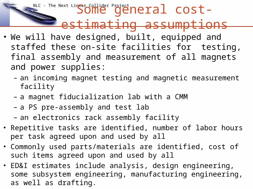
• We will have designed, built, equipped and staffed these on-site facilities for testing, final assembly and measurement of all magnets and power supplies:– an incoming magnet testing and magnetic measurement facility
– a magnet fiducialization lab with a CMM
– a PS pre-assembly and test lab
– an electronics rack assembly facility
• Repetitive tasks are identified, number of labor hours per task agreed upon and used by all
• Commonly used parts/materials are identified, cost of such items agreed upon and used by all
• ED&I estimates include analysis, design engineering, some subsystem engineering, manufacturing engineering, as well as drafting.

NLC - The Next Linear Collider Project
CD0.4 Magnet specific costing guidelines
Electromagnet Specific Assumptions:• Solid steel cores, low carbon steel prices• Hollow core copper conductor; Potted coils• SLAC style insulation and epoxy• Agreed upon list of components• Fabricated offshore: use offshore labor codes
PS Specific Assumptions:• Every group of same style PS has one “quick spare” PS added to cost [no 2-for-1
redundancy]• Use 1999 catalog price of existing standard commercial PS reduced by 10%• Same controller cost for every PS system
DC Power Cable Specific Assumptions:• Cable lengths assume cut & cover tunnels and TEEs: shorter cables than in
Lehman.• Cable size are > NEC [ reduce heat put into beamline housings.]

NLC - The Next Linear Collider Project
Typical Electromagnet Costing Process
Is a “bottom-up” process, assume small quantity:• Choose a spec’d magnet with a layout drawing• Make a parts list• Make a drawing list: how many, what size.• Make a B+H task list• Determine materials costs using common prices• Estimate hours for fab’ing each part
– For standard parts use NLC list of costs – use outside vendor estimate or ask SLAC shops [remember they give high estimates]– ask Magnet Engineer– use appropriate labor type, use offshore labor rates
• Calculate fabrication costs, apply learning curve for higher quantity if not inherently in the hours estimate– chose learning curve percentage appropriate to the mix of hand assembly and machining
• Estimate drafting hours using NLC list of hours per drawing by complexity and size.• Compare result with historical data on similar magnets, both from SLAC or other
labs.

NLC - The Next Linear Collider Project
Cable and Tray Costing Process• For Lehman did detailed, bottom-up beamline by beamline
cost estimates• Material cost based on RS Means Electrical Cost Data or
vendor quotes• Installation labor hours based on above RS Means -
#hours/feet length of size X cable; Ysize tray.• For CD0.4 has removed many cables completely , estimated rest in
detail
• Engineering estimated at 20% of M&S, then divided between phases
• Cable sizes-larger than National Electrical Code:• Injector NEC +2• DR NEC + 1• Main Linac NEC + 5• Beam Delivery NEC + 3

25th April 2006 Cherrill Spencer,SLAC Design Approach ILC Conv Magnets
16
MOST CHALLENGING ASPECT OF ILC CONVENTIONAL MAGNETS: MAKING THEM RELIABLE ENOUGH
Consider the availability requirements of the ILC as set out in the BCD
A good idea for each engineer to read Chapter 10 of the BCD Got to this URL and download the Operations and Reliability
chapter: http://www.linearcollider.org/wiki/doku.php?id=bcd:bcd_home Describes a simulation of the whole ILC that has been developed and the
model’s output tells you how long the ILC will be down it its components have certain mean time between failures (MTBF) and certain times to repair (Mean Time to Repair MTTR).
OVERALL ILC UPTIME GOAL IS 85% during the official runs of 9 months per year
25th April 2006 Cherrill Spencer,SLAC Design Approach ILC Conv Magnets
17
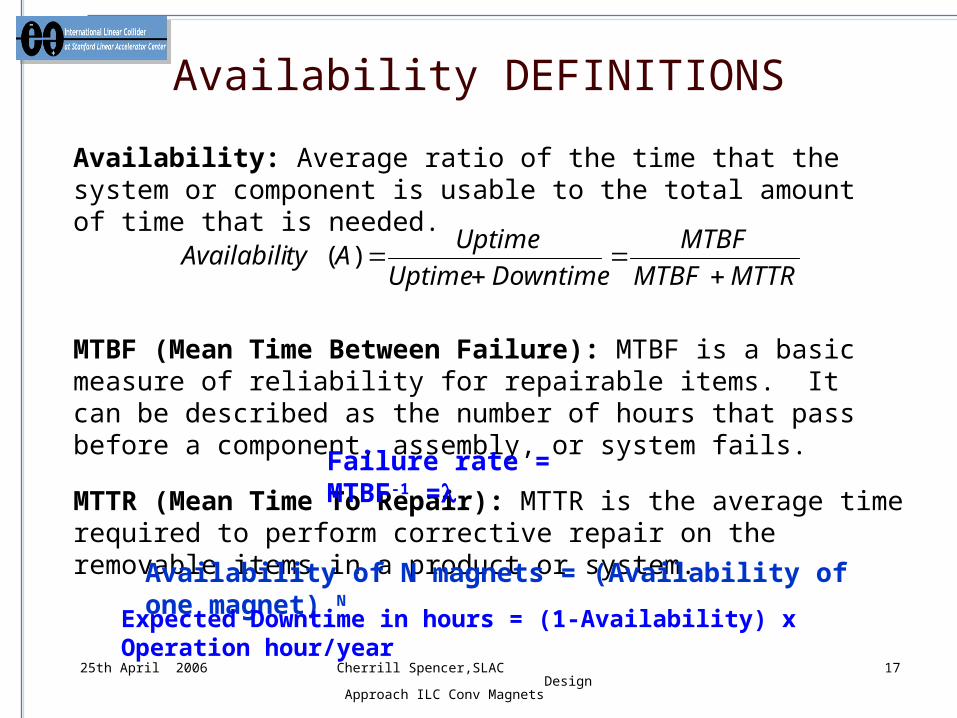
Availability: Average ratio of the time that the system or component is usable to the total amount of time that is needed.
MTBF (Mean Time Between Failure): MTBF is a basic measure of reliability for repairable items. It can be described as the number of hours that pass before a component, assembly, or system fails.
MTTR (Mean Time To Repair): MTTR is the average time required to perform corrective repair on the removable items in a product or system.
MTTRMTBF
MTBF
DowntimeUptime
UptimeAtyAvailabili
)(
Failure rate = MTBF-1 =
Availability of N magnets = (Availability of one magnet) N
Availability DEFINITIONS
Expected Downtime in hours = (1-Availability) x Operation hour/year

25th April 2006 Cherrill Spencer,SLAC Design Approach ILC Conv Magnets
18
How total allowed downtime of 17% is distributed among tech systems (assuming 17% = 15%)
Cryo8%
Vacuum16%
Magnets5%
AC power7%
controls17% Diagnostic
0%
RF structure7%
Water system11%
PS + controllers17%
RF power sources12%
Magnets allowed 5% of 17%=>0.8%
All ~12600 magnets allowed to be down 0.8% of ILC running time.Same as need to be up 99.2% of time!
In certain scenario each magnet’s MTBF has to be 20 million hours

25th April 2006 Cherrill Spencer,SLAC Design Approach ILC Conv Magnets
19
Measuring Electromagnet Availability atStanford Linear Accelerator Center
1. Obtain magnet failure history (CATER system) for 5 year period (1997-2001)
2. Categorize data into solid wire and water-cooled electromagnet types. 3. Calculate average beam downtime for different types of magnet from
failure data. 4. Obtain SLAC beamlines runtime schedule for this 5 year period.5. Count number of magnets in each SLAC beamline during specific
runtime periods. 6. Identify magnet failures that shut down the beam from CATER system
report for each runtime period. [CATER is an accelerator failure tracking database]
7. Calculate magnet operating hours by multiplying number of magnets by run hours for each period.
8. Calculate MTBF, MTTR and availability of one magnet for each period. 9. Calculate average availability for one magnet using all or some subset of
the SLAC beamlines’ data. This process repeated for switching power supply failures over same period.

25th April 2006 Cherrill Spencer,SLAC Design Approach ILC Conv Magnets
20
Summary of SLAC magnet & PS failure dataDates line ran
Beam-line
Run Hours
No. of Magnets
Magnet Hours
No. of failures
MTBF hours
Time to repair
MTTR hours
Availability of ONE magnet
5/1/97-6/8/98 SLC 8828 1087 (solid) 9,596,036 0 - 0 0 1 5/1/97-6/8/98 SLC 8828 2302 (water) 20,322,056 32 635,064 469.5 14.67 0.999976898
1/12/00-10/31/00
PEPII 6624 1690 (solid) 10,658,016 3 3,552,672 19.0 6.33 0.999998217
1/10/01-12/31/01
PEPII 7411 2602 (water) 17,235,648 7 2,754,774 37.9 5.41 0.999998035
1/1/02-12/31/02
ALL* 6480 1865 (water) (average No)
12,083,738* 1 12,083,738 3.0 3.0 0.999999752
Dates line ran
Beam-line
Run Hours
No. of switching PS
PS Hours No. of failures
MTBF hours
Time to repair hours
MTTR hours
Availability of ONE sw PS
2/24/99-5/1/99
Linac 1461 52 (small) 75,972 1 75,972 0.5 0.5 0.9999934
5/1/97-6/8/98 SLC +HER
8828 + 918
85 + 171(large)
907,358 5 181,472 10.3 2.06 0.9999886
1/10/01-12/31/01
PEPII 7411 425 (large) 3,180,835 27 117,809 45.9 1.70 0.9999856
“solid “= magnets with solid wire coils; “water” = magnets with water cooled coils; small PS <12A, <50V; large PS >12A,>50V. “Time to repair” is the total hours the beam was down for the stated failures, so MTTR = Time
to repair/No. of failures.

25th April 2006 Cherrill Spencer,SLAC Design Approach ILC Conv Magnets
21
How the MTBF value can vary depending on time period studied, choice of magnets
From SLAC 1997-2001 data: water cooled electromagnet’s average MTBF was 1,150,000 hours, i.e. about 1/20th of what the ILC needs!
But– look at a different period and eliminate the worst offenders: * This 2002 dataset does not include any magnets in the 2 SLC damping
rings, which have notoriously failure-prone magnets—by removing them from the dataset one can make the average MTBF vastly longer: 12,000,000 hours,. We understand why the DR magnets fail more frequently and would avoid making the same design mistakes in ILC magnets.
IN ANY EVENT, FOR THE ILC, WE CANNOT DESIGN AND FABRICATE MAGNETS LIKE WE HAVE BEEN DOING FOR THE PAST ~40 YEARS AT SLAC.
We have to carry out a detailed Failure Modes and Effects Analysis (FMEA) to learn how to revise our magnet designs and fabrication techniques to make more reliable magnets

25th April 2006 Cherrill Spencer,SLAC Design Approach ILC Conv Magnets
22
When we really get to design the ILC magnets we will have to do FMEAs on basic magnet styles
Failure Mode and Effects Analysis (FMEA) process considers each mode of failure of every component of the system, identifies their causes and ascertains the effects of each failure mode on system operation (ALL ILC components should have FMEA done on them).
As we cost estimate the ILC magnets we will have to account for the cost of doing FMEAs and paying for some higher quality materials and more expensive processes.
The causes of the most severe and likely to occur failures of a standard SLAC water- cooled electromagnet were identified as (a) water leaks and corrosion (b) various assembly errors.
Design changes were made in the conductor, terminals, core & numbers of items.

25th April 2006 Cherrill Spencer,SLAC Design Approach ILC Conv Magnets
23
FABRICATION FEATURES of E-M QUAD DRIVEN BY RELIABILITY OR COST NEEDS
Solid C1006 steel core, 4 quadrants ground on the outside; 4 pieces bolted together and the 4 poletips & coil pockets EDM’d in the same operation: 0.005mm reproducibility on the poletips; better coil pocket stability and tolerances. Machining cost less.
•Hollow seamless ROUND copper tubing (per ASTM B75) used for conductor, several advantages compared to square conductor: easier to wind; not prone to twisting; does not keystone; much smoother internal surface with many less crevices and defects where corrosion can start; allows direct attachment to compression fittings. Coil winding cost less.
•New style power terminals: commercial motor disconnects, modified to be brazed onto the conductor coil leads: cheaper and more reliable than custom made multifunction terminals
•Potted coils instead of wet lay-up: better dimensional stability and water resistance. The reduction in number of coils shorting out from nearby water leaks worth the higher cost.
Prototype quad was made and has been run for many hours over 4 year period in a measurement set-up without any failures