applicationguid e - titus hvac heater application guide.pdf · applicationguid e improved electric...
TRANSCRIPT

AG-EHeat-00June 4, 2001
Application Guide
Improved Electric Heater Design
AG-EHeat-00June 4, 2001
1
Table of Contents
Introduction 2NEC Clearance Requirements 2
Titus New Heater Requirements 3Titus Old Style Heater Requirements 4Nailor 35S “Stealth” with Hines Discharge Mounted Controls Requirements 5Nailor 35S “Stealth” with Standard Controls Requirements 6ETI CFR Requirements 7Trane VFPE Requirements 8Krueger KQFS Requirements 9NEC Clearance Requirements Summary 10
Airflow Considerations 11CFM vs. kW Based on ∆T across the Coil Chart 12
Amperage Calculations for ESV’s 13
AG-EHeat-00June 4, 2001
2
Introduction
Thermal comfort is the number one goal of an HVAC system. Cooling a zone from overheaddiffusers is a relatively straightforward process. Overhead heating is a more difficult application.The relationship between volume of air (CFM), temperature of air (∆T), and the kW required tosatisfy the zone is a simple calculation. With the introduction of the new, improved electricheater, we are providing this Application Guide to assist in the selection of electric coils.
NEC Clearance Requirements
One consideration we took into account when we began the electric heater redesign, was NECclearance requirements. We did not want to exceed the requirements of our old design, especially inthe width dimension.
NEC states that “working space for equipment operating at 600 volts, nominal, or less to ground andlikely to require examination, adjustment, servicing, or maintenance while energized shall complywith the dimensions of (1), (2), and (3)…in this Code.” (1) Depth of Working Space states that theminimum clear distance for 0-150 volt is 3 ft. and 151 to 600 volts is 3 ½ ft.. (2) Width of WorkingSpace states that the minimum width of the space shall be the width of the equipment or 30 in.,whichever is greater.
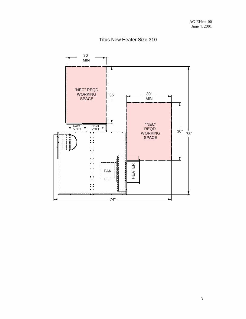
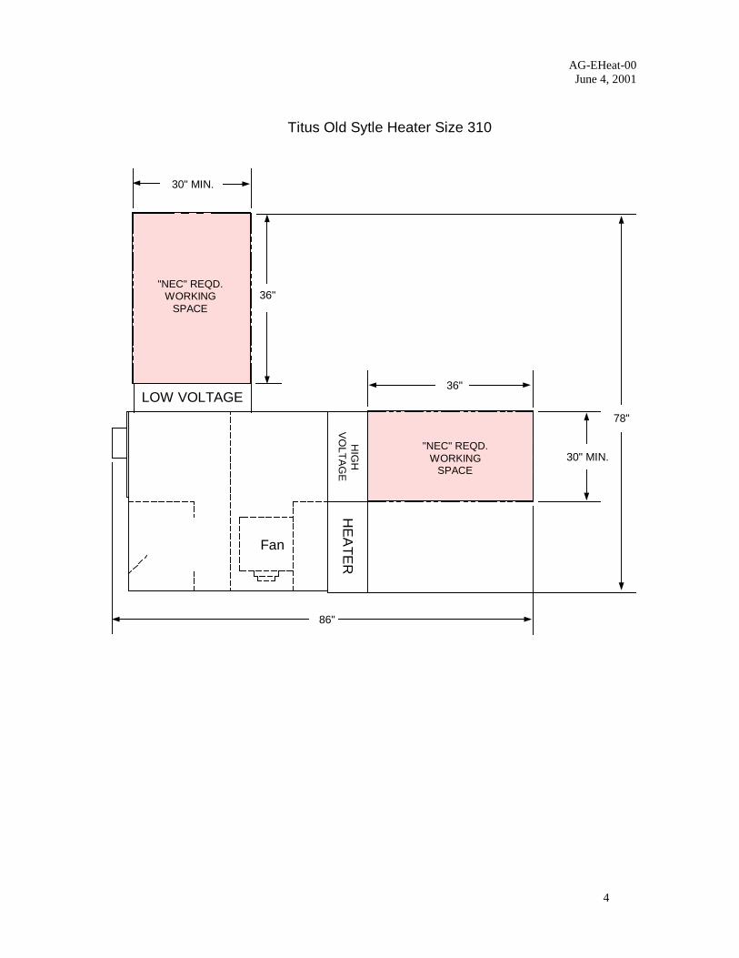
The following pages show the NEC required space of the Titus old and new design units and some ofthe competitions units. The series fan box sizes shown were selected to represent units with similarairflow requirements and therefore be comparable units for any given application. The units wereselected for 1200 CFM.
The drawings are not submittal drawings, so they are not exact, but should give a basis ofcomparison. They are laid out one per page so that you may lay one on top of another and get an ideaof the difference in NEC required clearance.
AG-EHeat-00June 4, 2001
3
Titus New Heater Size 310
"NEC" REQD.WORKING
SPACE
30"MIN
HE
AT
ER
LOWVOLT
HIGHVOLT
FAN
"NEC"REQD.
WORKINGSPACE
30"MIN
36"
36"
78"
74"
AG-EHeat-00June 4, 2001
4
Titus Old Sytle Heater Size 310
Fan
78"
30" MIN.
86"
HE
AT
ER
36"
LOW VOLTAGE
"NEC" REQD.WORKING
SPACE
36"
"NEC" REQD.WORKING
SPACE
HIG
HV
OL
TA
GE
30" MIN.
AG-EHeat-00June 4, 2001
5
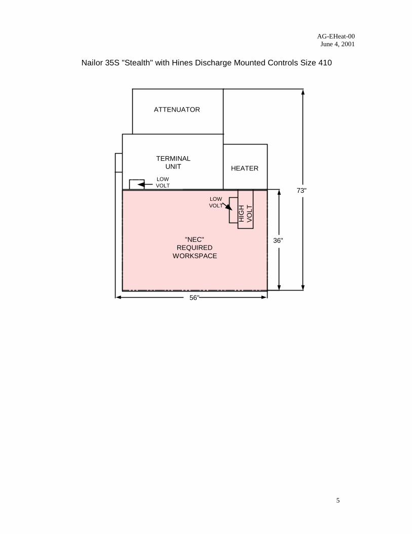
Nailor 35S "Stealth" with Hines Discharge Mounted Controls Size 410
ATTENUATOR
TERMINALUNIT HEATER
HIG
HV
OLT
LOWVOLT
73"
36"
56"
"NEC"REQUIRED
WORKSPACE
LOWVOLT
AG-EHeat-00June 4, 2001
6
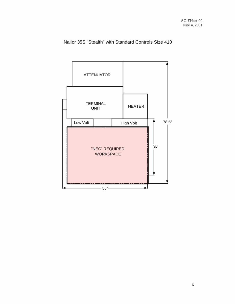
Nailor 35S "Stealth" with Standard Controls Size 410
"NEC" REQUIREDWORKSPACE
36"
HEATERTERMINAL
UNIT
ATTENUATOR
78.5"
56"
Low Volt High Volt

AG-EHeat-00June 4, 2001
7
ETI CFR Size 1217
36"
TERMINALUNIT
INLET
HE
AT
ER
HIGH VOLTCONTROL
BOX
"NEC"REQUIRED
WORKSPACE
LOW VOLTCONTROL
BOX
74"
56"
AG-EHeat-00June 4, 2001
8
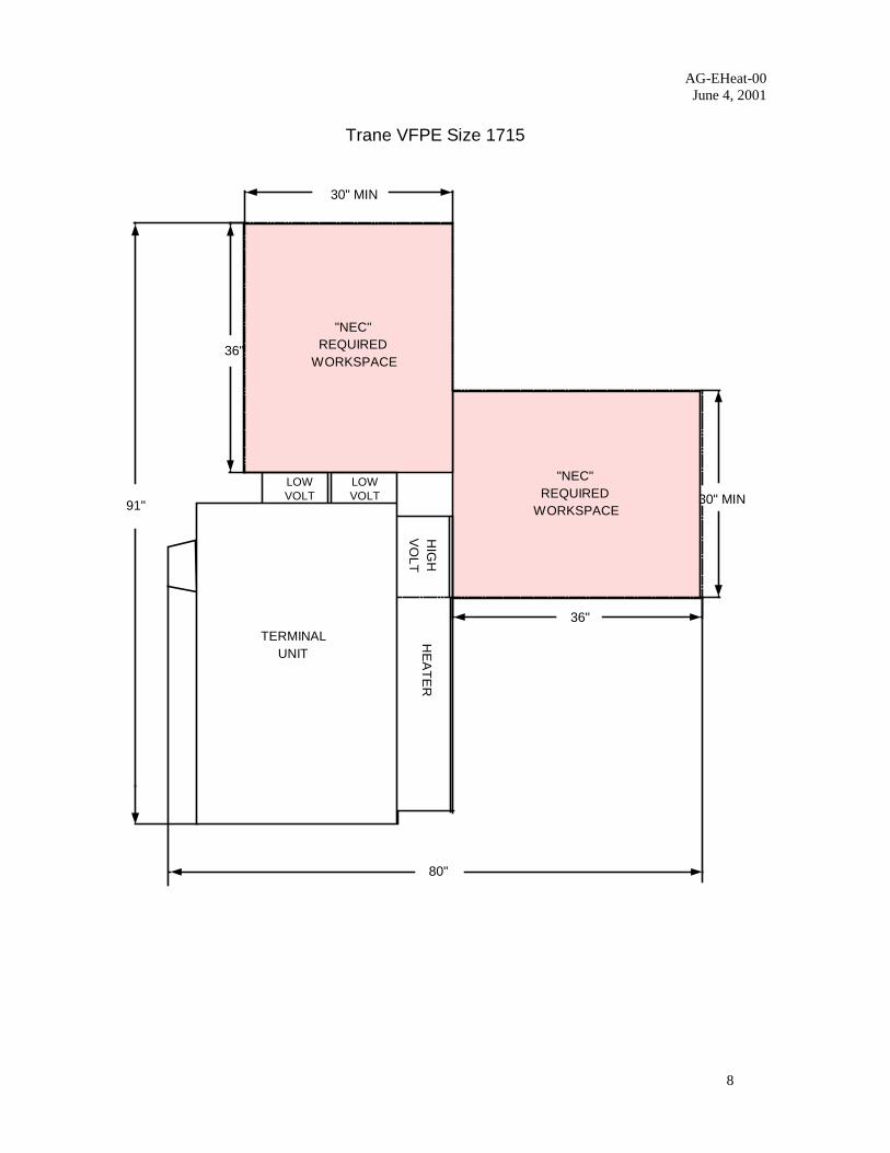
Trane VFPE Size 1715
"NEC"REQUIRED
WORKSPACE
"NEC"REQUIRED
WORKSPACE
TERMINALUNIT
HE
AT
ER
HIG
HV
OL
T
30" MIN
30" MINLOWVOLT
LOWVOLT
36"
91"
36"
80"
AG-EHeat-00June 4, 2001
9
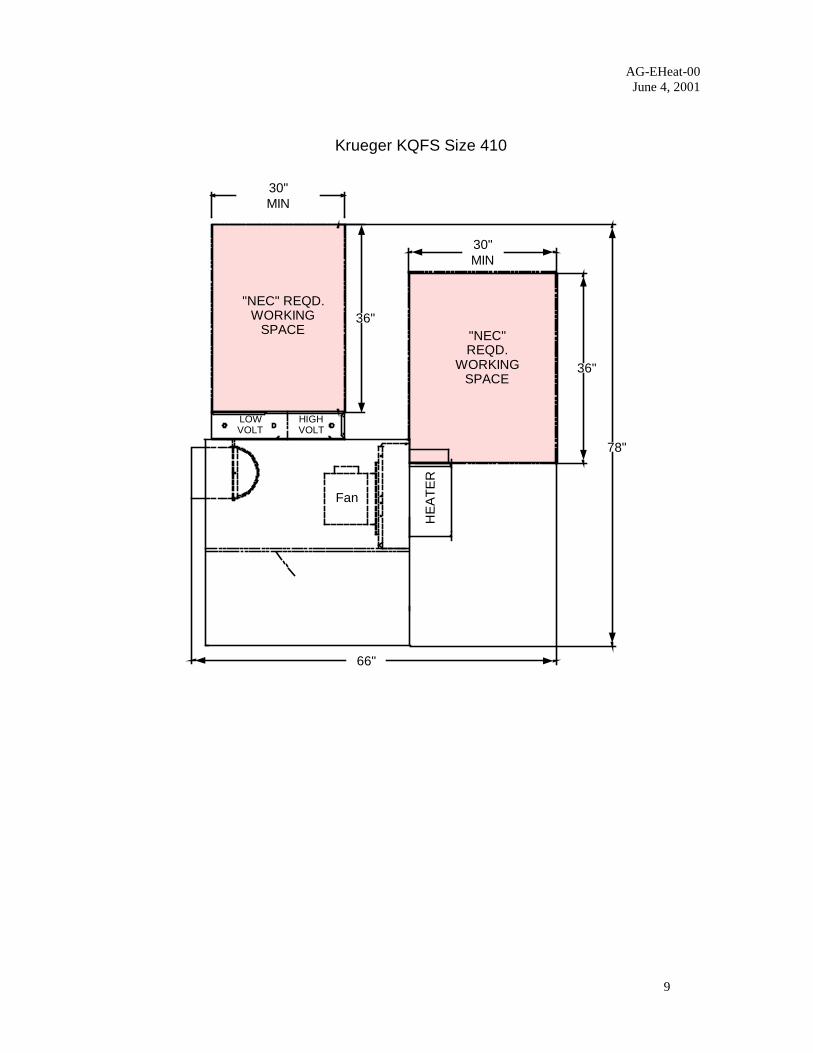
Krueger KQFS Size 410
"NEC" REQD.WORKING
SPACE
30"MIN
HE
AT
ER
LOWVOLT
HIGHVOLT
"NEC"REQD.
WORKINGSPACE
30"MIN
36"
36"
78"
66"
Fan
AG-EHeat-00June 4, 2001
10
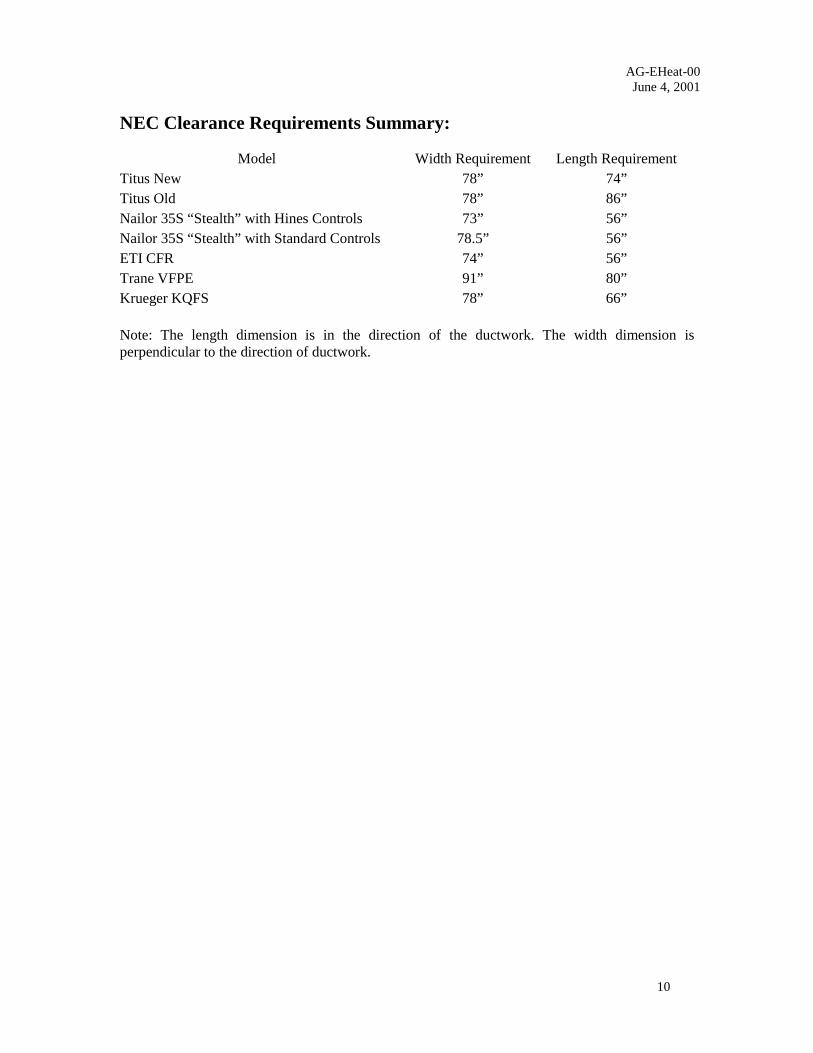
NEC Clearance Requirements Summary:
Model Width Requirement Length RequirementTitus New 78” 74”Titus Old 78” 86”Nailor 35S “Stealth” with Hines Controls 73” 56”Nailor 35S “Stealth” with Standard Controls 78.5” 56”ETI CFR 74” 56”Trane VFPE 91” 80”Krueger KQFS 78” 66”
Note: The length dimension is in the direction of the ductwork. The width dimension isperpendicular to the direction of ductwork.
AG-EHeat-00June 4, 2001
11
Airflow Considerations
As part of the design process, we reviewed our kW and low flow offerings and expanded theirranges whenever possible. You will notice that many of the kW ranges have been expanded and480V heaters are now available on ESV sizes 4, 5, and 6.
The improved design allows for better low flow performance. You must still consider theminimum CFM per kW and ∆T temperature rise when selecting the electric heater. We typicallyrecommend 70 CFM per kW for minimum CFM selection.
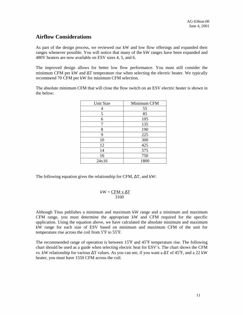
The absolute minimum CFM that will close the flow switch on an ESV electric heater is shown inthe below:
Unit Size Minimum CFM4 555 856 1057 1358 1909 225
10 30012 42514 57516 750
24x16 1800
The following equation gives the relationship for CFM, ∆T, and kW:
kW = CFM x ∆T 3160
Although Titus publishes a minimum and maximum kW range and a minimum and maximumCFM range, you must determine the appropriate kW and CFM required for the specificapplication. Using the equation above, we have calculated the absolute minimum and maximumkW range for each size of ESV based on minimum and maximum CFM of the unit fortemperature rise across the coil from 5oF to 55oF.
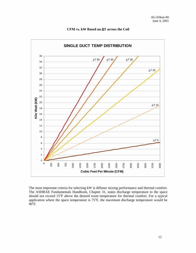
The recommended range of operation is between 15oF and 45oF temperature rise. The followingchart should be used as a guide when selecting electric heat for ESV’s. The chart shows the CFMvs. kW relationship for various ∆T values. As you can see, if you want a ∆T of 45oF, and a 22 kWheater, you must have 1550 CFM across the coil.
AG-EHeat-00June 4, 2001
12
CFM vs. kW Based on ∆∆∆∆T across the Coil
The most important criteria for selecting kW is diffuser mixing performance and thermal comfort.The ASHRAE Fundamentals Handbook, Chapter 31, states discharge temperature to the spaceshould not exceed 15oF above the desired room temperature for thermal comfort. For a typicalapplication where the space temperature is 75oF, the maximum discharge temperature would be90oF.
SINGLE DUCT TEMP DISTRIBUTION
0
2
4
6
8
10
12
14
16
18
20
22
24
26
28
30
32
34
36
0
250
500
750
1000
1250
1500
1750
2000
2250
2500
2750
3000
3250
3500
3750
4000
Cubic Feet Per Minute (CFM)
Kilo
Wat
t (kW
)
∆T 5
∆T 15
∆T 25
∆T 35∆T 45∆T 55

AG-EHeat-00June 4, 2001
13
Amperage Calculations for ESV’s
The following table shows the amperage for various heater voltages and kW’s.
120V 208V 208V 240V 277V 480V
1φ 1φ 3φ 1φ 1φ 3φ
3413 1 8.33 4.81 2.78 4.17 3.61 1.20
6826 2 16.67 9.62 5.56 8.33 7.22 2.41
10239 3 25.00 14.42 8.34 12.50 10.83 3.61
13652 4 33.33 19.23 11.12 16.67 14.44 4.82
17065 5 41.67 24.04 13.90 20.83 18.05 6.02
20478 6 50.00 28.85 16.68 25.00 21.66 7.23
23891 7 33.65 19.46 29.17 25.27 8.43
27304 8 38.46 22.32 33.33 28.88 9.63
30717 9 43.27 25.01 37.50 32.49 10.84
34130 10 48.08 27.79 41.67 36.10 12.04
37543 11 30.57 45.83 39.71 13.25
40956 12 33.35 43.32 14.45
44369 13 36.13 46.93 15.66
47782 14 38.91 16.86
51195 15 41.69 18.06
54608 16 44.47 19.27
58021 17 20.47
61434 18 21.68
64847 19 22.88
68260 20 24.08
71673 21 25.29
75086 22 26.49
78499 23 27.70
81912 24 28.90
85325 25 30.11
88738 26 31.31
92151 27 32.51
95564 28 33.72
98977 29 34.92
102390 30 36.13
105803 31 37.33
109216 32 38.54
112629 33 39.74
116042 34 40.94
119455 35 42.15
122868 36 43.35
Formula for caclulating line currents of electric coils:
Convert kW to W ATTS: kW x 1000 = W ATTS
Single Phase 1φ Three Phase 3φ
W ATTS
Line Voltage
208 x 1.73 = 359.8
480 x 1.73 = 830.4
AMPERES
BTUH kW
AMPERES = AMPERES =W ATTS
Line Voltage x 1.73