application of active base isolation controlsstl.cee.illinois.edu/papers/spie09_ming.pdf · ·...
TRANSCRIPT

Application of Active Base Isolation Control
Chia-Ming Chang*, Zhihao Wang, Billie F. Spencer Dept. of Civil and Environmental Engineering, Univ. of Illinois at Urbana-Champaign, Urbana, IL,
61801, USA
ABSTRACT
The structural control can provide the potential protection through passive and active control techniques. Structures with base isolations have been successfully implemented and proven effective in the vibration mitigation. To enhance the functionality of base isolations, a hybrid control system can be considered using a combination with active control devices. This research applies the hybrid control technique to a three-story two-bay steel building. The base isolation is installed under the structural base, and three actuators are placed at the lowest level. The control objective is to reduce the structural responses in the motion of three directions. First, the control system has been identified through the proposed system identification technique and considered with the control-structure interaction. Different controllers are designed to examine the performance under different types of excitation. Finally, this control system is tested on the shake table for evaluation of the controllers, and the two-dimensional control strategy is also realized through the whole procedures. Keywords: base isolation, system identification, structural control, control-structure interaction, LQG control algorithm
1. INTRODUCTION Base isolation systems have been demonstrated to be able to reduce the structural responses under seismic excitation. Passive base isolation has been widely applied to either buildings or bridges because of its cost-effectiveness and the simplicity of its implementation. These systems usually consist of rubber bearings and lead rubber bearings for increasing the structural flexure and the structural natural period. For example, the rubber bearings are installed underneath the structural base, the first natural frequency will be decreased compared to the original one. Therefore, the base displacement may become large, even exceed the prescribed limit. To reduce the displacement of the isolation layer, those bearings are designed in accordance to the level of the vibration, such as the earthquake input, to guarantee the performance. However, the nonlinear devices may not be able to promise the behavior under various seismic excitations, and then the design of these isolation bearings cannot be optimal for structures against external inputs. Considering the stochastic characteristics of an earthquake, a larger base displacement might occur for a stronger maximum credible earthquake (MCE), thus the revisions to the International Uniform Building Code (ICBO 1997) mandate the consideration of larger base displacement. To enhance the functionality of passive base isolation, active control or semi-active control base isolation systems are a feasible alternative. Hybrid base isolation systems with semi-active devices [1], named smart base isolation systems, have been proven to be effective against a wide range of ground excitations. The smart base isolation systems can potentially reduce the associated displacement at base and slightly increase the structural acceleration. However, smart base isolation systems have certain limitations on control performance due to the capacity of the semi-active devices. Alternately, hybrid base isolation systems with active devices are another technique to avoid the drawbacks of smart base isolation systems. This type of hybrid systems is able to mitigate the base displacement without increasing the absolute acceleration of structures. Hydraulic actuators are usually used in the application of structural control. Inaudi and Kelly [2] have examined the active base isolation system through an experiment in 1990. Also, Nagarajaiah et al [3] developed different control strategies applied to a sliding isolated bridge experimentally. Those experiments only focused on the one directional excitation and control; however, the idea of active base isolation systems should be able to extend to a generalized application of structural control, such as two or three dimensional control. Structures usually have planar motions at base under excitations, although sometimes the lifting force still contributes to structures dramatically. A benchmark control problem for an isolated building [4], which considered the dynamic behavior in two directions, was proposed to evaluate the control performance through different combinations of control systems and
Sensors and Smart Structures Technologies for Civil, Mechanical, and Aerospace Systems 2009edited by Masayoshi Tomizuka, Chung-Bang Yun, Victor Giurgiutiu, Proc. of SPIE Vol. 7292
729239 · © 2009 SPIE · CCC code: 0277-786X/09/$18 · doi: 10.1117/12.821827
Proc. of SPIE Vol. 7292 729239-1

different control strategies in simulation. The practical implementation, even through experiments, unfortunately still lacks of researchers and engineers to work on. To extend active base isolation systems in motion of multiple directions, a model which is able to describe the whole system well is required. Generally, a structural system can be identified through structural response measures and understandings in the input excitation. The system consisted of input and output information is basically named an input/output (I/O) system. An I/O system can usually be represented in a numerical form either in time domain or in frequency domain. The state-space representation is commonly used to express a system in time domain that the form comprises a relationship between inputs and outputs. Based on the relationship, a numerical realization in the state-space form can be successfully identified through a method, namely subspace state-space system identification [5]. The method considers the deterministic part and the stochastic part to form a system in time domain, and the result can represent the characteristics of the whole system as well. However, a complex control system needs an accurate realization in the dynamic behavior, especially in frequency domain. A system describing in the state-space form can be converted into the frequency domain using the Fourier transform. A convention way to express the system in frequency domain is transfer functions (TF), a fraction form with frequency variables. Auweraer [6] introduced a fast way to fit TF curves using the least-square method with a special setting on weighting functions. This technique is able to fit the TF poles and to minimize the noise induced from the input and output measurement at the same time. Kim [7] also developed a graphic user interface tool, named MFDID, to estimate transfer functions for a system based on a series of LS algorithms. Those approaches aim in fitting TF curves without considering the stabilization of TF poles. Once a non-iterative method can be developed, the loadings on computation will be saved. In this study, a simplified method for TF estimation is proposed that both effects are considered and included in the curve fitting. An active base isolation system requires an adequate controller to drive active devices reaching the control objective, for example, reducing the base displacement without increasing the absolute acceleration. Dyke [8] proposed a control strategy using the acceleration feedback to the controller in an application of an active control system. She used the linear-quadratic-Gaussian (LQG) algorithm to calculate the required command for an active mass driver, and then the structural response was successfully decreased. The control scheme using the LQG control algorithm works for the application of structural control that the required command of control force is optimally obtained from the structural response sensed. To substitute the control devices into actuators, Dyke [9] also designed an experiment to employ one actuator on a three-story building. The application feeds the floor acceleration back to the controller, and then the controller generates appropriate commands to the actuator for controlling the structural system. These experiments have proven the LQG control algorithms sufficiently to apply in the structural control. However, different control devices will induce different dynamic behavior for structures. Dyke [10] discovered that the characteristics of hydraulic actuators should be taken account into the controller design. Through looking at the transfer function from the actuator command to the floor acceleration, some poles and zeros of the transfer function were shifted, and the TF from the actuator command to its displacement did not remain flat. The effect is called control-structure interaction, which is well known for the shake table testing. Once the controller design can be considered with the control-structure interaction, the controller would be more robust and effective. This paper experimentally investigates active base isolation control strategies by employing spatial active control actuators. The control subject is a base-isolated steel frame model which is connected with three actuators at the base isolation layer. The control system is examined on a shake table in the Smart Structures Technology Laboratory at the University of Illinois at Urbana-Champaign. A simplified system identification method in frequency domain is proposed to estimate the mathematical model including the dynamic properties of the base isolated structure and the actuators. The LQG control algorithm is employed to obtain the optimal control force for mitigating the structural responses. Furthermore, the control-structure interaction is considered in the modeling and the controller design. Different control strategies with different system setups are tests along either single direction or multiple directions. The control effectiveness of the active base isolation control system is finally evaluated under 50 Hz band-limited white noise (BLWN) excitations.
Proc. of SPIE Vol. 7292 729239-2

2. EXPERIMENTAL SETUP A model building structure is selected to perform the active base isolation system. The small-scaled building consists of three stories with two bays that three 45” x 28” x 1” steel plates are attached to each floor with 360 lbs a piece. The floor plates are supported by six columns per floor, where each column is made in 100 ksi steel. This model building is originally designed for an existing building that will be retrofitted with an active base isolation system; in the mean time they share very similar dynamic characteristics. To implement active base isolation on this model building, an isolation layer with three actuators at the base is used. The isolation layer is a seismic isolation platform which is developed by WorkSafe Technologies for protecting important facilities in a building. The ISO-Base unit has a 3” tall platform to resist earthquake ground motions for valuable equipments through two conical load plates around a 1” baa bearing. In addition to the isolation layer, three small actuators with a stroke of 4.38” in the back and forth directions have a force capacity of 750 lbs each at 3000 psi for realizing active control. The active base isolation system is settled on a six degrees-of-freedom (DOFs) shake table. The shake table is able to accelerate up to 2g horizontally and 1g vertically. The controller, named SC-6000 servo control system, is developed by the Shore Western manufacture to drive the shake table. The complete experimental setup appears in Figure 1.
Fig. 1. The model building mounted on the 6-DOFs shake table in the Smart Structures Technology Laboratory
at the University of Illinois at Urbana-Champaign. The structural responses play an important role to generate the commands from the design controller to those actuators. Three accelerometers are placed at each of floor levels in the Y-direction in which there is only one actuator. Six accelerometers are separately placed in the X1- and X2-directions that the bottom right one and bottom left actuators are defined as X1 and X2 in Figure 1, respectively. Two accelerometers are placed on the table edge to measure the ground accelerations. Each actuator attaches one LVDT to measure the displacement at the base.
3. SYSTEM IDENTIFICATION Before designing the controller for this active base isolation system, a promising system model is required. The model has to accurately present the relationship between the inputs to the system and corresponding outputs. Due to the assumption that the system behaves linearly and time-invariantly, the linear system identification method based on the curve-fitting of the transfer functions is employed to obtain the system model. A linear time-invariant system with the information of inputs and outputs is able to translate into a mathematical form in frequency domain. The state-space representation conventionally attracts researchers to use in the controller design but
Proc. of SPIE Vol. 7292 729239-3
the transfer functions are still able to interpret a system and be converted into the state-space form. First, the transfer functions of an I/O system is presented,
( ) ( )( )
1,1 1,,
,
,1 ,
, 2, , , exp , 1 , 12,
nui k
i k
ny ny nu
h hB z m Nz h z j m jA z N
h h
π⎡ ⎤⎢ ⎥ ⎛ ⎞= = = − = = −⎜ ⎟⎢ ⎥ ⎝ ⎠⎢ ⎥⎣ ⎦
θH θ
θ
L
M O M
L
(1)
Here, H is the transfer function expression in the matrix form, Bi,k and Ai,k are in the form of polynomials, θ indicates the polynomial coefficients, ny and nu are respectively the number of inputs and outputs, N is the amount of the total data points in frequency domain. Note that the order n of the polynomial function in A indicates the order of the system, which is consistent to the dimension of the matrix A in the state-space representation. The transfer functions shown in the Eq. (1) is a discrete form that all roots of A are the poles lying in a unit circle. The roots of Bi,k are the zeros which depend on the input and the output. In general, the order of each Bi,k must be less than or equal to n, otherwise the transfer function will diverge to infinite. Through the LS algorithm, the transfer function is estimated by minimizing the objective function
( ) ( )( ) 2
, , ,1 1 1
arg min ( , ) ( , ) ( )ny nfnu
ri k f i k f f i k f
i k fW z B z A z h z
= = =
= −∑∑∑θL θ θ θ (2)
Here, Wi,k is the weighting function to make the poles and the zeros fitted well. Note that r denotes the real transfer functions directly derived from measurement, and nf denotes the number of the fitting points. When the system is a multiple-input and multiple-output (MIMO) system, the cross terms in hr should be considered. The Eq. (2) can be expanded into a linear algebraic problem that unnecessarily implies to obtain the solution iteratively.
1,1
2,1
,
1,1 1,1 1,1 1,1
2,1 2,1 2,1 2,1
1,1 1,1 2,1 2,1 , ,1 1
i k
H H
BH H
B
Bny nuH H H
i k i k Ai k= =
⎡ ⎤Γ Γ Γ Φ ⎧ ⎫⎢ ⎥ ⎪ ⎪Γ Γ Γ Φ⎢ ⎥ ⎪ ⎪⎢ ⎥ ⎪ ⎪ =⎢ ⎥ ⎨ ⎬⎢ ⎥ ⎪ ⎪⎢ ⎥ ⎪ ⎪⎢ ⎥ ⎪ ⎪Φ Γ Φ Γ Φ Φ ⎩ ⎭⎢ ⎥⎣ ⎦
∑∑
0 0 θ0 0 θ
0θ
θ
L
L
M O MM
L
(3)
where
, 1
, 2 0 1, , ,
,
( )( )
, ( ) ( )
( )
i k
i k nBi k i k f j k f f f f
i k nf
zz
z W z z z z
z
Γ⎧ ⎫⎪ ⎪Γ⎪ ⎪ ⎡ ⎤Γ = Γ =⎨ ⎬ ⎣ ⎦⎪ ⎪⎪ ⎪Γ⎩ ⎭
LM
(4)
, 1
, 2 0 1, , , ,
,
( )( )
, ( ) ( ) ( )
( )
i k
i k r nAi k i k f i k f i k f f f f
i k nf
zz
z W z G z z z z
z
Φ⎧ ⎫⎪ ⎪Φ⎪ ⎪ ⎡ ⎤Φ = Φ = −⎨ ⎬ ⎣ ⎦⎪ ⎪⎪ ⎪Φ⎩ ⎭
LM
(5)
Here, nB and nA are the polynomial order of the numerator and the denominator of the transfer functions, respectively. Notice that the matrix in the Eq. (3) is linearly dependent and therefore one coefficient in Aθ must be 1. After solving the Eq. (3), a set of polynomial coefficients is given that the roots of A are able to fit the poles of the transfer functions, but the roots of B may or may not fit all the zeros of the transfer functions. Sometimes the poles become unstable because those poles are outside the unit circle in the complex plane. In this system identification method, all poles are enforced into the unit circle by equalizing the distance toward the circumference. Therefore, performing the convention LS algorithm to iteratively solve all B again is able to capture all the zeros using the found A in the step 1. In fact, the step 2 is unnecessarily done at one time because one transfer function is independent to the other. Figure 2 shows the
Proc. of SPIE Vol. 7292 729239-4
EXP ID
50 100 150Freq.(Hz)
Channell
EXP ID
-20
EXP ID
50 100 150Freq.(Hz)
Channel2
50 100 150 0 50 100 150Freq.(Hz) Freq.(Hz)
Channell Channel2
-20
60
200
100
-100
-200
200
100
-100
EXP ID
Freq.(Hz) Freq.(Hz)
20
-20
-40
-60
-80
-100
200
100
-100
Channell20
-20
-40
-60
-80
100
200
100
-100
-200
Channel2
EXP ID EXP ID
50 100 150Freq.(Hz)
Channell
50 100 150Freq.(Hz)
Channel2
EXP ID EXP ID
50 100 150 50 100 150
10 20 30Exp. -ID
40 50Exp. -ID
10 20 30 40 50
200
100
-100
-200
Exp. -ID
200
100
-100
200
Exp. -ID10 20 30 40 50 10 20 30 40 50
Exp. -ID Exp. -ID
200
100
-100
-20010 20 30 40 50
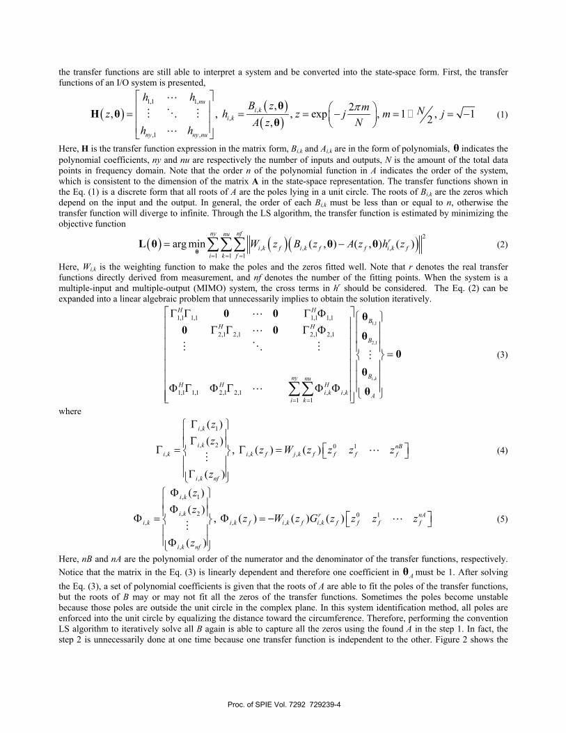
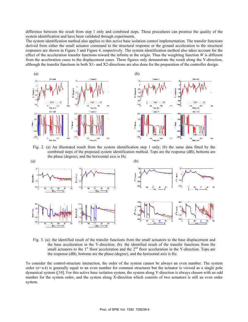
difference between the result from step 1 only and combined steps. These procedures can promise the quality of the system identification and have been validated through experiments. The system identification method also applies to this active base isolation control implementation. The transfer functions derived from either the small actuator command to the structural response or the ground acceleration to the structural responses are shown in Figure 3 and Figure 4, respectively. The system identification method also takes account for the effect of the acceleration transfer functions toward the infinite at the origin. Thus the weighting function W is different from the acceleration cases to the displacement cases. These figures only demonstrate the result along the Y-direction, although the transfer functions in both X1- and X2-directions are also done for the preparation of the controller design. (a) (b)
Fig. 2. (a) An illustrated result from the system identification step 1 only; (b) the same data fitted by the combined steps of the proposed system identification method. Tops are the response (dB), bottoms are the phase (degree), and the horizontal axis is Hz.
(a) (b)
Fig. 3. (a): the identified result of the transfer functions from the small actuators to the base displacement and the base acceleration in the Y-direction; (b): the identified result of the transfer functions from the small actuators to the 1st floor acceleration and the 2nd floor acceleration in the Y-direction. Tops are the response (dB), bottoms are the phase (degree), and the horizontal axis is Hz.
To consider the control-structure interaction, the order of the system cannot be always an even number. The system order (n=nA) is generally equal to an even number for common structures but the actuator is viewed as a single pole dynamical system ([10]. For this active base isolation system, the system along Y-direction is always chosen with an odd number for the system order, and the system along X-direction which consists of two actuators is still an even order system.
Proc. of SPIE Vol. 7292 729239-5
200
100
-100
200
- 1oo_
30 40 50
Exp. -ID Exp. -ID
200
1001
-100-
2000 10 50
200
- 100
-100
200
(a) (b)
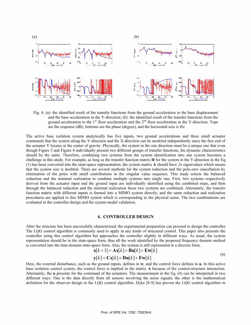
Fig. 4. (a): the identified result of the transfer functions from the ground acceleration to the base displacement and the base acceleration in the Y-direction; (b): the identified result of the transfer functions from the ground acceleration to the 1st floor acceleration and the 2nd floor acceleration in the Y-direction. Tops are the response (dB), bottoms are the phase (degree), and the horizontal axis is Hz.
The active base isolation system analytically has five inputs, two ground accelerations and three small actuator commands that the system along the Y-direction and the X-direction can be modeled independently since the free end of the actuator Y locates at the center of gravity. Physically, the system in the one direction must be a unique one that even though Figure 3 and Figure 4 individually present two different groups of transfer functions, the dynamic characteristics should be the same. Therefore, combining two systems from the system identification into one system becomes a challenge in this study. For example, as long as the transfer function matrix H for the system in the Y-direction in the Eq. (1) has been converted into the state-space representation, the system matrix A should have 2n eigenvalues which means that the system size is doubled. There are several methods for the system reduction and the pole-zero cancellation by elimination of the poles with small contributions in the singular value sequence. This study selects the balanced reduction and the minimal realization to combine multiple systems into single one. First, two systems respectively derived from the actuator input and the ground input are individually identified using the combined steps, and then through the balanced reduction and the minimal realization those two systems are combined. Alternately, the transfer function matrix with different inputs is formed into a MIMO system directly, and the same reduction and realization procedures are applied to this MIMO system which is corresponding to the physical sense. The two combinations are evaluated in the controller design and the system model validation.
4. CONTROLLER DESIGN After the structure has been successfully characterized, the experimental preparation can proceed to design the controller. The LQG control algorithm is commonly used to apply in any kinds of structural control. This paper also presents the controller using this control algorithm but approaches the controller slightly in different ways. As usual, the system representation should be in the state-space form, thus all the work identified by the proposed frequency domain method is converted into the time-domain state-space form. Also, the system is still represented in a discrete form,
[ 1] [ ] [ ] [ ][ ] [ ] [ ] [ ]k k k kk k k k+ = + += + +
x Ax Bu Ewy Cx Du Fw
(6)
Here, the external disturbance, such as the ground inputs, defines in w, and the control force defines in u. In this active base isolation control system, the control force is implied in the matrix A because of the control-structure interaction. Alternately, the u presents for the command of the actuators. The measurement in the Eq. (6) can be interpreted in two different ways. One is the data directly from all sensors involving the noise signals; the other is the mathematical definition for the observer design in the LQG control algorithm. Dyke [8-9] has proven the LQG control algorithm in
Proc. of SPIE Vol. 7292 729239-6

details and experimentally verified in the active control system. The LQG control algorithms consists of the design of two different gains, the control gain with respect to (A,B) and the Kalman gain with respect to (A,C,E) in the Eq. (6). The control gain is to calculate the control force using the structural states optimally, and the Kalman gain is derived from the well-known Kalman filter which can translate the measurement into the structure states, namely the observer. The combination of two gains is eventually formed as
ˆ ˆ[ 1] ( ) [ ] [ ]
ˆ[ ] [ ]k k kk k+ = − − += −
x A BG LC x Lyu Gx
(7)
where G denotes the control gain which is also called feedback gain and L is the Kalman gain. The state-space representation of systems is originally derived from the equation of motion in a numerical form; however, the state-space form obtained directly from the system identification is difficultly converted into the same numerical form. Instead, the eigen domain for the state-space representation can express the dynamic system in the same way that the canon form is introduced. The canon form of the state-space representation is to transform the system matrix A into a block diagonal matrix, where each block equals a matrix with a pair of conjugate complex eigenvalues as well as the eigenvalues of the original matrix A. Note that all blocks belongs to real values. Therefore, the weighting function for the control gain design is place on the modes of the system, including the single mode for the actuators. The Kalman gain is able to weight on the measures. To compare the LQG controller design in simulation, the weighting subjects are changed from the structural states to the modes for the control gain in this new approach. This study considers the examination of the controller before implementing the active base isolation control system. A quick way to examine the controller is to test the open-loop gain, sending signals to the control system and computing the required commands. For example, a BLWN excitation is sent to the actuator, the structural responses are induced by the actuator vibration, and finally those responses are fed back to the controller for obtaining the commands for use in the control. The input and the output are commands that if they are consistent, the transfer function between two command signals will be equal to one. If the response of the transfer function is always below one, the control system will stay stable as well as the uncontrolled case. Therefore, the transfer function response from the control loop gain test has to be greater than one. For the noisy range, the loop gain response of the transfer function has to be below one due to the consideration of the safety. The design objective of the controller in this study is to reduce the base displacement and the floor absolute accelerations at the same time. After observing the system transfer functions, the first mode mostly denominates the system responses. The controller obviously focuses on the first mode reduction in the beginning. To compare the responses induced by the small actuators and the ground accelerations, the weighting function for measurement in the Kalman gain design is put on the acceleration responses slightly more than the base displacement, that is, the reduction on the first mode directly affected to the base displacement.
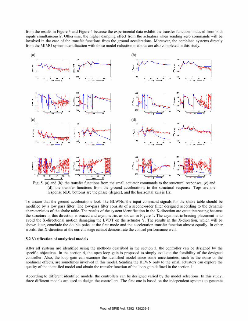
5. EXPERIMENTAL RESULTS The active base isolation control system has a complicated behavior in the dynamic characteristics and the control design. The low-damping effect of the isolation easily makes the system unstable if the controller is not under complete consideration. Fully understanding the control problem can guarantee either the control performance or the safety of the structure. The followings are the step-by-step procedures to accomplish the active base isolation control problem and demonstrate the associated results. 5.1 Control system models Due to the transfer function estimation, the system identification is conducted in frequency domain only. A 50 Hz band-limited white noise is always specified to the input signals either for the small actuators or for the shake table. Figure 3 and Figure 4 have already shown the identification results depending on two different systems from the small actuator commands and the ground accelerations to the structural response, respectively. In the section 3, the combined system to form a complete control system has been addressed. After two individual systems are combined together, Figure 5 shows the results that although the balanced reduction and the minimal realization eliminate some modes from the original combined system, the curve fitting to the transfer functions are still acceptable. The experimental results look different
Proc. of SPIE Vol. 7292 729239-7
200
100
-100
-20050
200
- 100
-100
10 20 30 40200
10 20 30 40 50
200
100
-100
-20010 20
Exp. -ID
30Exp. -ID
40 50
Exp. -ID
Exp. -ID
Bas
e D
isp.
Bas
e A
ccel
.
20010 30 40 50
from the results in Figure 3 and Figure 4 because the experimental data exhibit the transfer functions induced from both inputs simultaneously. Otherwise, the higher damping effect from the actuators when sending zero commands will be involved in the case of the transfer functions from the ground accelerations. Moreover, the combined systems directly from the MIMO system identification with those model reduction methods are also completed in this study. (a) (b)
(c) (d)
Fig. 5. (a) and (b): the transfer functions from the small actuator commands to the structural responses; (c) and (d): the transfer functions from the ground accelerations to the structural response. Tops are the response (dB), bottoms are the phase (degree), and the horizontal axis is Hz.
To assure that the ground accelerations look like BLWNs, the input command signals for the shake table should be modified by a low pass filter. The low-pass filter consists of a second-order filter designed according to the dynamic characteristics of the shake table. The results of the system identification in the X-direction are quite interesting because the structure in this direction is braced and asymmetric, as shown in Figure 1. The asymmetric bracing placement is to avoid the X-directional motion damaging the LVDT on the actuator Y. The results in the X-direction, which will be shown later, conclude the double poles at the first mode and the acceleration transfer function almost equally. In other words, this X-direction at the current stage cannot demonstrate the control performance well. 5.2 Verification of analytical models After all systems are identified using the methods described in the section 3, the controller can be designed by the specific objectives. In the section 4, the open-loop gain is proposed to simply evaluate the feasibility of the designed controller. Also, the loop gain can examine the identified model since some uncertainties, such as the noise or the nonlinear effects, are sometimes involved in this model. Sending the BLWN only to the small actuators can explore the quality of the identified model and obtain the transfer function of the loop gain defined in the section 4. According to different identified models, the controllers can be designed varied by the model selections. In this study, three different models are used to design the controllers. The first one is based on the independent systems to generate
Proc. of SPIE Vol. 7292 729239-8

5 10 15 20 25 30 35 40 45 50freq.(Hz)
200
5 10 15 20 25 30 40 45 50freq.(Hz)
100-
40
200
5 10 15 20 25 30freq.(Hz)
20 25 30 35freq.(Hz)
35 40 45
40
Ex.
50
50
20
-20-
-40-
-60-
-80-
Sim. Exp.
-20
-40
-60
10 20 30 40 50freq.(Hz)
10 20 30 40 50freq.(Hz)
200
100
-100
10 20 30freq.(Hz)
100
200
40 50 0 10 20 30freq.(Hz)
40 50
the controller. One assumption is adhesive that the matrix E is substituted into the matrix B in the Eq. (6). For the system with only one actuator, the way to design controller is promising but once the control system consists of more than two actuators, the phase effect sufficiently influences the control performance, even damages the structure. This study does not consider this controller design to the X-direction for sure. Therefore, there are three different controllers of the actuator Y, and two controllers are designed for both X-direction actuators. When testing the loop gain in the Y-direction, the zero commands are continuously sending to the actuator X1 and X2, and vice versa. Figure 6 shows the loop gain results from the individual system for controller design at left and the directly identified MIMO system to generate the controller at right, which are defined as the controller Y-1 and the controller Y-2, respectively. This figure has verified that the model developed from those identification methods works sufficiently for the controller design. The figure can also predict the control performance through the pole values that the controller Y-1 should have better performance than the controller Y-2. (a) (b)
Fig. 6. (a): the loop gain obtained from the controller Y-1; (b): the loop gain obtained from the controller Y-2. Tops are the responses of the transfer functions, bottoms are the phases of the transfer functions.
The controller for the actuator X1 and X2 are also designed. Only one controller is studied in this paper that the controller, named the controller X, is derived from the model of the combined system using three independent systems, which are the systems with inputs from the actuator X1, the actuator X2, and the ground acceleration. Figure 7 shows the loop gain for the controller X.
Fig. 7. The loop gains obtained from the controller X. The results of the actuator X1 and X2 are at left and right,
respectively. The results in Figure 7 look very noisy at the high frequency range because there are some measurement noise and uncertainties existing in those transfer functions. However, as the former description, the motion induced by the ground
Proc. of SPIE Vol. 7292 729239-9
50
-50
10 20 30 40 50freq. (Hz)
Zero Command- ControI
10 20 30 40 50freq. (Hz)
ZeroCommand-ControI
.1
200
-100
10 20 30 40 50freq. (Hz)
Zero Command- ControI
40 5010 20 30freq. (Hz)
Zero Command- ControI
50
-50
10 20 30 40 50freq. (Hz)
Zero Command- ControI
10 20 30 40 50freq. (Hz)
Zero Command- ControI
I33V
00
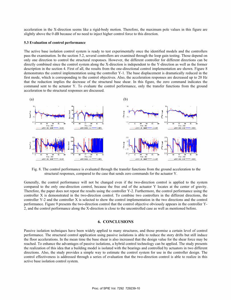
acceleration in the X-direction seems like a rigid-body motion. Therefore, the maximum pole values in this figure are slightly above the 0 dB because of no need to inject higher control force to this direction. 5.3 Evaluation of control performance The active base isolation control system is ready to test experimentally once the identified models and the controllers pass the examination. In the section 5.2, several controllers are examined through the loop gain testing. Those depend on only one direction to control the structural responses. However, the different controller for different directions can be directly combined since the control system along the X-direction is independent to the Y-direction as well as the former description in the section 4. First of all, the results from the one-directional control implementation are shown. Figure 8 demonstrates the control implementation using the controller Y-1. The base displacement is dramatically reduced in the first mode, which is corresponding to the control objectives. Also, the acceleration responses are decreased up to 20 Hz that the reduction implies the decrease of the structural base shear. In this figure, the zero command indicates the command sent to the actuator Y. To evaluate the control performance, only the transfer functions from the ground acceleration to the structural responses are discussed. (a) (b)
Fig. 8. The control performance is evaluated through the transfer functions from the ground acceleration to the structural responses, compared to the case that sends zero commands for the actuator Y.
Generally, the control performance will not be changed even if the two-direction control is applied to the system compared to the only one-direction control, because the free end of the actuator Y locates at the center of gravity. Therefore, the paper does not repeat the results using the controller Y-2. Furthermore, the control performance using the controller X is demonstrated in the two-direction control. To combine two controllers in the different directions, the controller Y-2 and the controller X is selected to show the control implementation in the two directions and the control performance. Figure 9 presents the two-direction control that the control objective obviously appears in the controller Y-2, and the control performance along the X-direction is close to the uncontrolled case as well as mentioned before.
6. CONCLUSIONS Passive isolation techniques have been widely applied to many structures, and those promise a certain level of control performance. The structural control application using passive isolations is able to reduce the story drifts but still induce the floor accelerations. In the mean time the base shear is also increased that the design value for the shear force may be reached. To enhance the advantages of passive isolations, a hybrid control technology can be applied. The study presents the realization of this idea that a building model is isolated with the bearings and controlled by actuators in two different directions. Also, the study provides a simple way to estimate the control system for use in the controller design. The control effectiveness is addressed through a series of evaluation that the two-direction control is able to realize in this active base isolation control system.
Proc. of SPIE Vol. 7292 729239-10

50
-50
200
100
-100
-200
10 20 30 40 50freq. (Hz)
Zero Command- ControI
50
10 20 30 40 50freq. (Hz)
Zero Command- ControI
4010 20 30freq. (Hz)
Zero Command- ControI
5010 20 30 40freq. (Hz)
Zero Command- ControI
50
-50
200
100
-100
-20050
10 20 30 40 50 10 20 30 40 50freq. (Hz) freq. (Hz)
Zero Command- ControI Zero Command- ControI
10 20 30 40 50freq. (Hz)
Zero Command- ControI
4010 20 30freq. (Hz)
Zero Command- ControI
50
-50
200
100
-100
-200
10 20 30 40 50freq. (Hz)
Zero Command- ControI
10 20 30 40 50freq. (Hz)
Zero Command- ControI
10 20 30 40 50freq. (Hz)
Zero Command- ControI
10 20 30 40 50freq. (Hz)
Zero Command- ControI
20
-20
200
100
-100
-20050
20
- 0
<20
-40
-6010 20 30 40 50 10 20 30 40 50
freq. (Hz) freq. (Hz)Zero Command- ControI Zero Command- ControI
10 20 30 40 50freq. (Hz)
Zero Command- ControI
4010 20 30freq. (Hz)
Zero Command- ControI
50
-50
200
100
-100
-200
10 20 30 40 50
freq. (Hz)Zero Command- ControI
50
10 20 30 40 50freq. (Hz)
Zero Command- ControI
4010 20 30freq. (Hz)
Zero Command- ControI
5010 20 30 40
freq. (Hz)Zero Command- ControI
00
gE0
gE0
I33VI33V
I33VI33V
To the current stage, the two-direction control strategy has successfully worked in this control system, but the control performance should be improved. The next stage in this research will focus on overcoming the control challenge along the X-direction and designing different controllers to make the control performance become better. Finally, alternative power sources for the actuators will be investigated, with the goal of powering the actuator during the first 60 seconds of an earthquake. (a) (b)
(c) (d)
(e) (f)
Fig. 9. (a) and (b): the control performance using the controller Y-2 in the Y-direction; (c) and (d): the control performance of the structural responses along the X1-direction using the controller X; (e) and (f): the control performance of the structural responses along the X2-direction using the controller X.
Proc. of SPIE Vol. 7292 729239-11

ACKNOWLEDGEMENTS The authors would like to acknowledge T.A. Mullenix and K.S. Park that they shared their valuable experience. The authors would also like to acknowledge the funding provided by National Science Council in Taiwan under Grant No. NSC-095-SAF-I-564-036-TMS and the funding provided by National Science Foundation under Grant No. 0600433 and 0301140. Finally, the authors still have to thank to WorkSafe Technologies for the generous donations of several ISO-Base units.
REFERENCES
[1] Ramallo, J. C., Johnson, E. A., and Spencer, J. F., “Smart base isolation system,” Journal of Engineering Mechanics, 128(10), 1088-1099 (2002).
[2] Inaudi, J. A., and Kelly, J. M., “Active isolation,: U.S. National Workshop on Structural Control Research, Los Angeles, 125-130 (1990).
[3] Nagarajaiah, S., Riley, M. A., and Reinhorn, A. M., “Control of sliding isolated bridge with absolute acceleration feedback,” Journal of Engineering Mechanics, 119(11), 2317-2332 (1993).
[4] Narasimhan, S., Nagarajaiah, S., Johnson, E. A., and Gavin, H. P., “Smart base-isolated benchmark building. Part I: problem definition,” Journal of Structural Control and Health Monitoring, 13(2-3), 573-588 (2006).
[5] van Overschee, P., and de Moore, B., “N4SID: Subspace algorithms for the identification of combined deterministic-stochastic systems,” Automatica, 30, 75-93 (1994).
[6] Auweraer, H. V. D., Guilaume, P., Verboven, P., and Vanlanduit, S., “Application of a fast-stabilizing frequency domain parameter estimation method,” Journal of Dynamic Systems, Measurement, and Control, 123, 651-658 (2001).
[7] Kim, S. B., Spencer, B. F., and Yun, C. B., “Frequency domain identification of multi-input, multi-output systems considering physical relationships between measured variables,” Journal of Engineering Mechanics, 131(5), 461-472 (2005).
[8] Dyke, S. J., Spencer, B. F., Quast, P., Kaspari, D. C., and Sain M.K., “Implementation of an active mass driver using acceleration feedback control,” Microcomputers in Civil Engineering: Special Issue on Active and Hybrid Structural Control, 11, 305-323 (1994).
[9] Dyke, S. J., Spencer, B. F., Quast, P., Sain, M. K., Kaspari, D. C., and Soong, T. T., “ Experimental verification of acceleration feedback control strategies for an active tendon system,” National Center for Earthquake Engineering Research Technical Report NCEER-94-0024, (1994).
[10] Dyke, S. J., Spencer, B. F., Quast, P., and Sain M. K., “The role of control-structure interaction in protective system design,” Journal of Engineering Mechanics, 121(2), 322-338 (1995).
Proc. of SPIE Vol. 7292 729239-12