application manual – part 1: basic data and preliminary ... · answers for infrastructure....
TRANSCRIPT

Answers for infrastructure.
Totally Integrated Power
Application Manual – Part 1:Basic Data and Preliminary Planning 2nd edition 2009
Integrated solutions for power distribution in commercial and industrial buildings
1 Introduction 1
1.1 Integrated Planning – Cost Reduction 2
2 Basic Data and Preliminary Planning 5
2.1 The Planner’s Tasks 6
2.2 Some Basic Considerations on Power Distribution 7
2.3 Standards, Regulations and Guidelines 16
2.4 Building Automation 17
2.5 Fire Protection and Security Systems 18
2.6 BACS and Danger Management Systems 21
3 Determining and Splitting the Power Demand and Budget 25
4 Power Distribution Planning in Commercial, Institutional and Industrial Buildings 29
4.1 Basics for Drafting Electrical Power Distribution Systems 30
4.2 Network Configurations and Supply Concepts 36
4.3 Power Supply with regard to Selectivity Evaluation (Examples) 54
5 Dimensioning of the Main Components for Power Supply 59
5.1 Medium-voltage Switchgear 60
5.2 Pressure Development in Switchgear Rooms 69
5.3 Distribution Transformers (GEAFOL) 70
5.4 Oil-immersed Distribution Transformers 75
5.5 Low-voltage Switchgear 79
5.6 Busbar Trunking Systems 96
5.7 Distribution Boards for Sub-distribution Systems 102
5.8 Uninterruptible Power Supply System (UPS) 104
5.9 Standby Power Supply 108
6 Building Management, Comfort and HVAC 117
6.1 Building Automation with Desigo 118
6.2 Heating, Ventilation, Air Conditioning (HVAC) 120
6.3 Planning Notes for GAMMA instabus (KNX/EIB) 123
6.4 Power Management 125
6.5 SICAM Power I&C System 134
7 Fire Protection 139
7.1 Risk and Fire Protection Planning 140
7.2 Fire Detection System 142
7.3 Fire Alarm Center and Systems Engineering 143
7.4 Alarm and Evacuation 144
7.5 Fire Extinguishing Systems 145
8 Security Systems 147
8.1 Robbery and Burglar Alarm Systems (RAS and BAS) 148
8.2 Video Surveillance Systems (CCTV) 150
8.3 Access Control 150
8.4 Danger Management System 151
9 Power Quality 153
9.1 Electromagnetic Compatibility (EMC) 154
9.2 Power Quality 162
9.3 Lightning Protection and Grounding 170
9.4 Integration of Regenerative Energy Sources 174
10 Lighting 179
10.1 Lighting of Indoor Workplaces 180
11 Energy-efficient Buildings 185
11.1 The Energy Certificate for Buildings 186
11.2 Effects of Building Automation Systems on the Energy Efficiency of Buildings 188
12 Tables and Overviews 191
12.1 Supply Network Operators in Germany and Ripple Control Frequencies 192
12.2 Cable Cross Sections and Lengths Depending on the Applied Motor 192
12.3 Utilization Categories acc. to DIN EN 60947-4-1, 3, 5-1 (VDE 0660 Parts 102, 107 and 200) 193
12.4 Rated Currents and Initial Symmetrical Short-circuit Currents of Three-phase Distribution Transformers with 50 up to 3,150 kVA 194
12.5 Fire Loads and Heating Values for Fire Protection Rating 195
12.6 Planning with Software Support 196
12.7 Terms and Definitions 198
12.8 Abbreviations 201
12.9 Contents: Application Manual – Part 2: Draft Planning 2007 202
Your Siemens Contact Partners 203
Contact Partners for Special Subjects 203
Imprint 204
Contents

Chapter 1Introduction
1.1 Integrated Planning – Cost Reduction 2
2 Totally Integrated Power – Introduction
11.1 Integrated Planning – Cost ReductionIncreasingly higher requirements are placed on modern buildings. As early as in the planning stage, demands for a high level of safety, flexibility throughout the entire life cycle, a low level of environmental pollution, the integra-tion of renewable energies and low costs must be taken into account in order to exploit the full potential.
In this context, a special challenge is the coordination of the individual installations. Basically, the main installations are heating, ventilation, air conditioning and refrigeration, fire protection, protection against burglary, building con-trol system and power distribution. In modern planning, the requirements are not simply broken down to the indi-vidual installations, but have to be coordinated.
The greatest potential for the optimization of a project is during the planning phase. At this stage, the course is set for additional costs and cost increases which may incur during the erection and subsequent use of the building.
For an integrated planning, the building is regarded as an entity, functionality is defined in line with the processes running without limiting it to the individual installations, as it used to be done in traditional approaches. To achieve this goal, it is necessary to define specifications with the corre-sponding scope as early as in the planning stage. This is the only way to implement a solution with optimally matched systems and components. A seamless, technical integration of the different systems will make it possible to attain maximum process efficiency and reliability. At the same
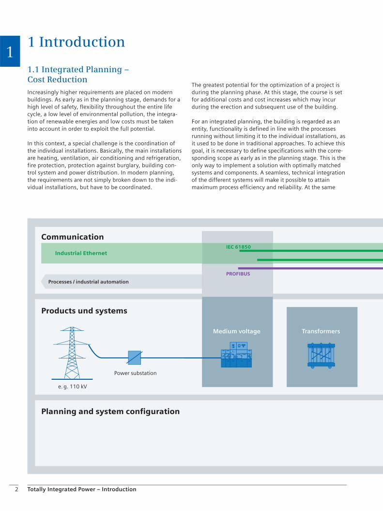
1 Introduction
Communication
Products und systems
Planning and system configuration
Processes / industrial automation
Medium voltage Transformers
Power substation
e. g. 110 kV
Industrial Ethernet
PROFIBUS
IEC 61850

3Totally Integrated Power – Introduction
1time, this is the way for reducing the costs for building investors, users and operators by exploiting synergies.
Integrated planning takes the synergies of well matched, intelligent, integrated systems and products from a single supplier into account and implements them in cost-effec-tive solutions. Elaborate interfacing and harmonization of different systems and products becomes obsolete. The expense for spare parts management and procurement is reduced. Communication systems can be used to connect power supply/distribution systems and products to other services such as automated process and production sys-tems or automated building management systems. The wiring expense can be substantially reduced by a well matched concept and the utilization of the cable infra-structure for data transmission which can be realized through such a concept.
These are merely some examples, how the cost-benefit ratio can be crucially improved by integrated planning as compared to conventional planning.
The focus of Totally Integrated Power™ lies on all power distribution components as an integrated entity. Totally Integrated Power offers everything that can be expected from a future-oriented power distribution system: open-ness, integration, efficient engineering tools, manifold options for communication and, of course, a substantial improvement in efficiency.
When looking at the requirements to power distribution as viewed from the installations of building automation, fire protection and security systems, the level of networking between these individual installations becomes soon apparent. The more these installations are networked, the higher their savings potential. Cost reductions up to 25% are feasible. Investors and operators can thus provide a cost-effective power supply system and boost their own efficiency. Users benefit from high-level electricity supply in both quality and quantity at favorable conditions.
Fig. 11/1: Totally Integrated Power – integrated solutions for power distribution
Low-voltagedistribution
Installation and low-voltage circuit protection
Buildingautomation
PROFINET
KNX
BACnet
KNXnet/IP

4 Totally Integrated Power – Introduction
1
Chapter 2Basic Data and Preliminary Planning
2.1 The Planner’s Tasks 6
2.2 Some Basic Considerations on Power Distribution 7
2.3 Standards, Regulations and Guidelines 16
2.4 Building Automation 17
2.5 Fire Protection and Security Systems 18
2.6 BACS and Danger Management Systems 21

6 Totally Integrated Power – Basic Data and Preliminary Planning
2
2 Basic Data and Preliminary Planning
2.1 The Planner’s Tasks
It is up to the planner to win an edge over his competitors and gain unique selling points by offering modern, innova-tive concepts for the layout of power supply systems and the selection of suitable equipment. But he is also respon-sible for his planning work, which means that he may be held liable for damages.
The first two project stages (Table 21/1) are of vital impor-tance in this context. They determine the basic set-up and guidelines for the further course of the project. Wrong assumptions and imprecise specifications may result either in system oversizing and, consequently, in unnecessary costs, or in undersizing and, consequently, in equipment overloading and failure. This manual, “Basic Data and Preliminary Planning,” shall assist you in sizing the compo-nents for technical installations in buildings properly even in the initial project stages. Its focus is on the components for electric power distribution.
Phase 1, Establishment of Basic Data
Task definition
Review of the project situation
Site analysis
Operational planning
Preparation of a room concept
Preparation of a concept on the functional scope
Environmental impact assessment
Recommendations for the total power demand
Formulation of decision-making aids for the selection of other experts involved in the planning
Summary of results
Table 21/1: Overview of the most important planner’s tasks in the first two project stages according to the HOAI (German Regulation of Architects’ and Engineers’ Fees) – Excerpt
Phase 2, Preliminary Planning (Project and Planning Preparations)
Analysis of the basis Coordination of objec-tives (boundary condi-tions, conflicting objectives)
Preparation of a planning concept incl. possible alternative solutions
Integration of services rendered by other experts involved in the planning
Clarification and expla-nation of the fundamen-tal interrelations, processes and conditions in the context of urban development and design, functions, technology, building physics, economics, energy management (e. g.
regarding efficient power utilization and the use of renewable energies) and landscape ecology, as well as the impact on and sensitivity of the affected ecosystems
Preliminary negotiations with public authorities and other experts involved in the planning as to whether an official approval can be obtained
Cost estimation in compliance with DIN 276 or according to statutory provisions for cost calculations of residen-tial dwellings
Compilation of all preliminary planning results
7Totally Integrated Power – Basic Data and Preliminary Planning
22.2 Some Basic Considerations on Power Distribution
Power demand
In terms of electric power supply, the most important task in the stage of establishing basic data is the estimation of the power quantity required for supply (Chapter 3). In order to attain a high level of efficiency, the components should work with a utilization of 70–80 % of the maximum power: Undersizing causes malfunctions, while oversizing results in excess costs.
Network configuration and sources of supply
The network configuration is determined dependent on the requirements drawn from the building’s use. In line with the specifications made by the installation company and the intended use of the building, the required power output must be distributed between different sources of supply. If redundancy is a system requirement, an additional reserve must be considered in the planning. Besides the demand to be met by the normal power supply (NPS), the power quantity required from a safe source of supply must also be estimated. This power demand is divided between the redundant power supply (RPS) and the uninterruptible power supply (UPS). When the NPS fails, the UPS shall be supplied from the RPS. In addition, the power requirements of safety equipment (DIN VDE 0100-710, DIN VDE 0100-718) to be supplied by the safety power supply system (SPS) must be considered. The estimates for the power quantities required and their allocation to different sources of supply finally render the dimensioning of individual components.
Technical equipment rooms
Besides a proper component dimensioning, another essen-tial planning aspect is the specification of the size and location of the technical equipment rooms required for power supply. The dimensions of these equipment rooms depend on the dimensions of the components required and the relevant safety regulations. Boundary conditions such as room ventilation, ceiling loads and access ways for moving items in must also be taken into consideration when drawing up room and building plans. Over-dimen-sioned rooms reduce the economic efficiency of a building (room utilization). Under-dimensioned rooms may hinder the implementation of a certain technical solution or, at least force the use of expensive custom solutions for the technology applied. This application manual contains aids for determining the room dimensions required for certain components.
8
Checklist
Totally Integrated Power – Basic Data and Preliminary Planning
2Review of the project situationEvery project is unique in its own way. For efficient planning, it is important to include as many influencing factors as possible in a checklist at the project start.
Type of building use
e. g. office, school, hotel, multi-purpose etc.
Operator concept
Is the owner / developer also the user of the real estate?
Goals of the operator regarding tenancy, variability and period of use?
Optimized costs of investment and operation (building energy performance, EnEV, etc.)
Level of building installations, equipment and furnishing
c high-level
c medium
c standard
Cost frame
Scheduled budget
Financing schemes / operator concepts
. . . . . . . . . . . . . . . . . . . . . . . . . . . . . . . . . . . . . . . . . . . . . . . . . . . . . . . . . . . . . . . . .
. . . . . . . . . . . . . . . . . . . . . . . . . . . . . . . . . . . . . . . . . . . . . . . . . . . . . . . . . . . . . . . . .
. . . . . . . . . . . . . . . . . . . . . . . . . . . . . . . . . . . . . . . . . . . . . . . . . . . . . . . . . . . . . . . . .
. . . . . . . . . . . . . . . . . . . . . . . . . . . . . . . . . . . . . . . . . . . . . . . . . . . . . . . . . . . . . . . . .
. . . . . . . . . . . . . . . . . . . . . . . . . . . . . . . . . . . . . . . . . . . . . . . . . . . . . . . . . . . . . . . . .
. . . . . . . . . . . . . . . . . . . . . . . . . . . . . . . . . . . . . . . . . . . . . . . . . . . . . . . . . . . . . . . . .
. . . . . . . . . . . . . . . . . . . . . . . . . . . . . . . . . . . . . . . . . . . . . . . . . . . . . . . . . . . . . . . . .
. . . . . . . . . . . . . . . . . . . . . . . . . . . . . . . . . . . . . . . . . . . . . . . . . . . . . . . . . . . . . . . . .
. . . . . . . . . . . . . . . . . . . . . . . . . . . . . . . . . . . . . . . . . . . . . . . . . . . . . . . . . . . . . . . . .
. . . . . . . . . . . . . . . . . . . . . . . . . . . . . . . . . . . . . . . . . . . . . . . . . . . . . . . . . . . . . . . . .
. . . . . . . . . . . . . . . . . . . . . . . . . . . . . . . . . . . . . . . . . . . . . . . . . . . . . . . . . . . . . . . . .
. . . . . . . . . . . . . . . . . . . . . . . . . . . . . . . . . . . . . . . . . . . . . . . . . . . . . . . . . . . . . . . . .
. . . . . . . . . . . . . . . . . . . . . . . . . . . . . . . . . . . . . . . . . . . . . . . . . . . . . . . . . . . . . . . . .
. . . . . . . . . . . . . . . . . . . . . . . . . . . . . . . . . . . . . . . . . . . . . . . . . . . . . . . . . . . . . . . . .
. . . . . . . . . . . . . . . . . . . . . . . . . . . . . . . . . . . . . . . . . . . . . . . . . . . . . . . . . . . . . . . . .
. . . . . . . . . . . . . . . . . . . . . . . . . . . . . . . . . . . . . . . . . . . . . . . . . . . . . . . . . . . . . . . . .
. . . . . . . . . . . . . . . . . . . . . . . . . . . . . . . . . . . . . . . . . . . . . . . . . . . . . . . . . . . . . . . . .
. . . . . . . . . . . . . . . . . . . . . . . . . . . . . . . . . . . . . . . . . . . . . . . . . . . . . . . . . . . . . . . . .
. . . . . . . . . . . . . . . . . . . . . . . . . . . . . . . . . . . . . . . . . . . . . . . . . . . . . . . . . . . . . . . . .
. . . . . . . . . . . . . . . . . . . . . . . . . . . . . . . . . . . . . . . . . . . . . . . . . . . . . . . . . . . . . . . . .
. . . . . . . . . . . . . . . . . . . . . . . . . . . . . . . . . . . . . . . . . . . . . . . . . . . . . . . . . . . . . . . . .
. . . . . . . . . . . . . . . . . . . . . . . . . . . . . . . . . . . . . . . . . . . . . . . . . . . . . . . . . . . . . . . . .
. . . . . . . . . . . . . . . . . . . . . . . . . . . . . . . . . . . . . . . . . . . . . . . . . . . . . . . . . . . . . . . . .
. . . . . . . . . . . . . . . . . . . . . . . . . . . . . . . . . . . . . . . . . . . . . . . . . . . . . . . . . . . . . . . . .
. . . . . . . . . . . . . . . . . . . . . . . . . . . . . . . . . . . . . . . . . . . . . . . . . . . . . . . . . . . . . . . . .
. . . . . . . . . . . . . . . . . . . . . . . . . . . . . . . . . . . . . . . . . . . . . . . . . . . . . . . . . . . . . . . . .
. . . . . . . . . . . . . . . . . . . . . . . . . . . . . . . . . . . . . . . . . . . . . . . . . . . . . . . . . . . . . . . . .
9
Checklist
Totally Integrated Power – Basic Data and Preliminary Planning
2Dimensions
Building area ............... m2
Building height ............... m
Average floor height ............... m
Number of floors ...............
Car park, access ways
Building use
Uniform use (e. g. offices)
Different use (e. g. shop, garage, office)
Limitations
Defined locations (for cable routing)
Maximal dimensions / weights for moving in installation components (observe transportation routes)
Specifications for emergency diesel unit (exhaust air, fuel-tank room)
. . . . . . . . . . . . . . . . . . . . . . . . . . . . . . . . . . . . . . . . . . . . . . . . . . . . . . . . . . . . . . . . .
. . . . . . . . . . . . . . . . . . . . . . . . . . . . . . . . . . . . . . . . . . . . . . . . . . . . . . . . . . . . . . . . .
. . . . . . . . . . . . . . . . . . . . . . . . . . . . . . . . . . . . . . . . . . . . . . . . . . . . . . . . . . . . . . . . .
. . . . . . . . . . . . . . . . . . . . . . . . . . . . . . . . . . . . . . . . . . . . . . . . . . . . . . . . . . . . . . . . .
. . . . . . . . . . . . . . . . . . . . . . . . . . . . . . . . . . . . . . . . . . . . . . . . . . . . . . . . . . . . . . . . .
. . . . . . . . . . . . . . . . . . . . . . . . . . . . . . . . . . . . . . . . . . . . . . . . . . . . . . . . . . . . . . . . .
. . . . . . . . . . . . . . . . . . . . . . . . . . . . . . . . . . . . . . . . . . . . . . . . . . . . . . . . . . . . . . . . .
. . . . . . . . . . . . . . . . . . . . . . . . . . . . . . . . . . . . . . . . . . . . . . . . . . . . . . . . . . . . . . . . .
. . . . . . . . . . . . . . . . . . . . . . . . . . . . . . . . . . . . . . . . . . . . . . . . . . . . . . . . . . . . . . . . .
. . . . . . . . . . . . . . . . . . . . . . . . . . . . . . . . . . . . . . . . . . . . . . . . . . . . . . . . . . . . . . . . .
. . . . . . . . . . . . . . . . . . . . . . . . . . . . . . . . . . . . . . . . . . . . . . . . . . . . . . . . . . . . . . . . .
. . . . . . . . . . . . . . . . . . . . . . . . . . . . . . . . . . . . . . . . . . . . . . . . . . . . . . . . . . . . . . . . .
. . . . . . . . . . . . . . . . . . . . . . . . . . . . . . . . . . . . . . . . . . . . . . . . . . . . . . . . . . . . . . . . .
. . . . . . . . . . . . . . . . . . . . . . . . . . . . . . . . . . . . . . . . . . . . . . . . . . . . . . . . . . . . . . . . .
. . . . . . . . . . . . . . . . . . . . . . . . . . . . . . . . . . . . . . . . . . . . . . . . . . . . . . . . . . . . . . . . .
. . . . . . . . . . . . . . . . . . . . . . . . . . . . . . . . . . . . . . . . . . . . . . . . . . . . . . . . . . . . . . . . .
. . . . . . . . . . . . . . . . . . . . . . . . . . . . . . . . . . . . . . . . . . . . . . . . . . . . . . . . . . . . . . . . .
. . . . . . . . . . . . . . . . . . . . . . . . . . . . . . . . . . . . . . . . . . . . . . . . . . . . . . . . . . . . . . . . .
. . . . . . . . . . . . . . . . . . . . . . . . . . . . . . . . . . . . . . . . . . . . . . . . . . . . . . . . . . . . . . . . .
. . . . . . . . . . . . . . . . . . . . . . . . . . . . . . . . . . . . . . . . . . . . . . . . . . . . . . . . . . . . . . . . .
. . . . . . . . . . . . . . . . . . . . . . . . . . . . . . . . . . . . . . . . . . . . . . . . . . . . . . . . . . . . . . . . .
. . . . . . . . . . . . . . . . . . . . . . . . . . . . . . . . . . . . . . . . . . . . . . . . . . . . . . . . . . . . . . . . .
. . . . . . . . . . . . . . . . . . . . . . . . . . . . . . . . . . . . . . . . . . . . . . . . . . . . . . . . . . . . . . . . .
. . . . . . . . . . . . . . . . . . . . . . . . . . . . . . . . . . . . . . . . . . . . . . . . . . . . . . . . . . . . . . . . .
. . . . . . . . . . . . . . . . . . . . . . . . . . . . . . . . . . . . . . . . . . . . . . . . . . . . . . . . . . . . . . . . .
. . . . . . . . . . . . . . . . . . . . . . . . . . . . . . . . . . . . . . . . . . . . . . . . . . . . . . . . . . . . . . . . .
. . . . . . . . . . . . . . . . . . . . . . . . . . . . . . . . . . . . . . . . . . . . . . . . . . . . . . . . . . . . . . . . .

10
Checklist
Totally Integrated Power – Basic Data and Preliminary Planning
2Energy passport
Facade design (let-through values)
Lighting (light design)
Room control functions (lighting, shutters and blinds)
Lighting (light design)
Safety requirements
Power supply
Fire lobbies
EMC
Video surveillance
Fire alarm system
Access control
Time recording
Security system
Safety-relevant installation parts
Depending on the building use
Elevators
Safety lighting for workplaces
Central batteries for safety lighting for meeting area
Sprinkler system / booster pumps
Lifting systems for sewage water draining
Smoke and heat vents (SHV)
Communications centers
Electro-acoustic centers (ELA)
Components of the video / security system
Secondary pipe heating for sprinkler pipes in cold area
Life-supporting systems
. . . . . . . . . . . . . . . . . . . . . . . . . . . . . . . . . . . . . . . . . . . . . . . . . . . . . . . . . . . . . . . . .
. . . . . . . . . . . . . . . . . . . . . . . . . . . . . . . . . . . . . . . . . . . . . . . . . . . . . . . . . . . . . . . . .
. . . . . . . . . . . . . . . . . . . . . . . . . . . . . . . . . . . . . . . . . . . . . . . . . . . . . . . . . . . . . . . . .
. . . . . . . . . . . . . . . . . . . . . . . . . . . . . . . . . . . . . . . . . . . . . . . . . . . . . . . . . . . . . . . . .
. . . . . . . . . . . . . . . . . . . . . . . . . . . . . . . . . . . . . . . . . . . . . . . . . . . . . . . . . . . . . . . . .
. . . . . . . . . . . . . . . . . . . . . . . . . . . . . . . . . . . . . . . . . . . . . . . . . . . . . . . . . . . . . . . . .
. . . . . . . . . . . . . . . . . . . . . . . . . . . . . . . . . . . . . . . . . . . . . . . . . . . . . . . . . . . . . . . . .
. . . . . . . . . . . . . . . . . . . . . . . . . . . . . . . . . . . . . . . . . . . . . . . . . . . . . . . . . . . . . . . . .
. . . . . . . . . . . . . . . . . . . . . . . . . . . . . . . . . . . . . . . . . . . . . . . . . . . . . . . . . . . . . . . . .
. . . . . . . . . . . . . . . . . . . . . . . . . . . . . . . . . . . . . . . . . . . . . . . . . . . . . . . . . . . . . . . . .
. . . . . . . . . . . . . . . . . . . . . . . . . . . . . . . . . . . . . . . . . . . . . . . . . . . . . . . . . . . . . . . . .
. . . . . . . . . . . . . . . . . . . . . . . . . . . . . . . . . . . . . . . . . . . . . . . . . . . . . . . . . . . . . . . . .
. . . . . . . . . . . . . . . . . . . . . . . . . . . . . . . . . . . . . . . . . . . . . . . . . . . . . . . . . . . . . . . . .
. . . . . . . . . . . . . . . . . . . . . . . . . . . . . . . . . . . . . . . . . . . . . . . . . . . . . . . . . . . . . . . . .
. . . . . . . . . . . . . . . . . . . . . . . . . . . . . . . . . . . . . . . . . . . . . . . . . . . . . . . . . . . . . . . . .
. . . . . . . . . . . . . . . . . . . . . . . . . . . . . . . . . . . . . . . . . . . . . . . . . . . . . . . . . . . . . . . . .
. . . . . . . . . . . . . . . . . . . . . . . . . . . . . . . . . . . . . . . . . . . . . . . . . . . . . . . . . . . . . . . . .
. . . . . . . . . . . . . . . . . . . . . . . . . . . . . . . . . . . . . . . . . . . . . . . . . . . . . . . . . . . . . . . . .
. . . . . . . . . . . . . . . . . . . . . . . . . . . . . . . . . . . . . . . . . . . . . . . . . . . . . . . . . . . . . . . . .
. . . . . . . . . . . . . . . . . . . . . . . . . . . . . . . . . . . . . . . . . . . . . . . . . . . . . . . . . . . . . . . . .
. . . . . . . . . . . . . . . . . . . . . . . . . . . . . . . . . . . . . . . . . . . . . . . . . . . . . . . . . . . . . . . . .
. . . . . . . . . . . . . . . . . . . . . . . . . . . . . . . . . . . . . . . . . . . . . . . . . . . . . . . . . . . . . . . . .
. . . . . . . . . . . . . . . . . . . . . . . . . . . . . . . . . . . . . . . . . . . . . . . . . . . . . . . . . . . . . . . . .
. . . . . . . . . . . . . . . . . . . . . . . . . . . . . . . . . . . . . . . . . . . . . . . . . . . . . . . . . . . . . . . . .
. . . . . . . . . . . . . . . . . . . . . . . . . . . . . . . . . . . . . . . . . . . . . . . . . . . . . . . . . . . . . . . . .
. . . . . . . . . . . . . . . . . . . . . . . . . . . . . . . . . . . . . . . . . . . . . . . . . . . . . . . . . . . . . . . . .
. . . . . . . . . . . . . . . . . . . . . . . . . . . . . . . . . . . . . . . . . . . . . . . . . . . . . . . . . . . . . . . . .
11
Checklist
Totally Integrated Power – Basic Data and Preliminary Planning
2Planning documents
Drawings, space assignment plans, utilization plans, tables on energy balance, technology descriptions, requirements, for example from installation rules for cabling, factory regulations and similar
Building regulations, conditions imposed by authorities
Depending on the building use, for example:
Installations for gathering of people (VDE 100, Part 718 – previously VDE 0108)
Medical locations (VDE 100, Part 710 – previously VDE 0107)
Hazardous locations
Areas for technical installations
Can existing rooms be used?
Requirements set by the power supply network operator –> Technical supply conditions (TAB)
Arrangement of areas / rooms (rising ducts, fire lobbies)
. . . . . . . . . . . . . . . . . . . . . . . . . . . . . . . . . . . . . . . . . . . . . . . . . . . . . . . . . . . . . . . . .
. . . . . . . . . . . . . . . . . . . . . . . . . . . . . . . . . . . . . . . . . . . . . . . . . . . . . . . . . . . . . . . . .
. . . . . . . . . . . . . . . . . . . . . . . . . . . . . . . . . . . . . . . . . . . . . . . . . . . . . . . . . . . . . . . . .
. . . . . . . . . . . . . . . . . . . . . . . . . . . . . . . . . . . . . . . . . . . . . . . . . . . . . . . . . . . . . . . . .
. . . . . . . . . . . . . . . . . . . . . . . . . . . . . . . . . . . . . . . . . . . . . . . . . . . . . . . . . . . . . . . . .
. . . . . . . . . . . . . . . . . . . . . . . . . . . . . . . . . . . . . . . . . . . . . . . . . . . . . . . . . . . . . . . . .
. . . . . . . . . . . . . . . . . . . . . . . . . . . . . . . . . . . . . . . . . . . . . . . . . . . . . . . . . . . . . . . . .
. . . . . . . . . . . . . . . . . . . . . . . . . . . . . . . . . . . . . . . . . . . . . . . . . . . . . . . . . . . . . . . . .
. . . . . . . . . . . . . . . . . . . . . . . . . . . . . . . . . . . . . . . . . . . . . . . . . . . . . . . . . . . . . . . . .
. . . . . . . . . . . . . . . . . . . . . . . . . . . . . . . . . . . . . . . . . . . . . . . . . . . . . . . . . . . . . . . . .
. . . . . . . . . . . . . . . . . . . . . . . . . . . . . . . . . . . . . . . . . . . . . . . . . . . . . . . . . . . . . . . . .
. . . . . . . . . . . . . . . . . . . . . . . . . . . . . . . . . . . . . . . . . . . . . . . . . . . . . . . . . . . . . . . . .
. . . . . . . . . . . . . . . . . . . . . . . . . . . . . . . . . . . . . . . . . . . . . . . . . . . . . . . . . . . . . . . . .
. . . . . . . . . . . . . . . . . . . . . . . . . . . . . . . . . . . . . . . . . . . . . . . . . . . . . . . . . . . . . . . . .
. . . . . . . . . . . . . . . . . . . . . . . . . . . . . . . . . . . . . . . . . . . . . . . . . . . . . . . . . . . . . . . . .
. . . . . . . . . . . . . . . . . . . . . . . . . . . . . . . . . . . . . . . . . . . . . . . . . . . . . . . . . . . . . . . . .
. . . . . . . . . . . . . . . . . . . . . . . . . . . . . . . . . . . . . . . . . . . . . . . . . . . . . . . . . . . . . . . . .
. . . . . . . . . . . . . . . . . . . . . . . . . . . . . . . . . . . . . . . . . . . . . . . . . . . . . . . . . . . . . . . . .
. . . . . . . . . . . . . . . . . . . . . . . . . . . . . . . . . . . . . . . . . . . . . . . . . . . . . . . . . . . . . . . . .
. . . . . . . . . . . . . . . . . . . . . . . . . . . . . . . . . . . . . . . . . . . . . . . . . . . . . . . . . . . . . . . . .
. . . . . . . . . . . . . . . . . . . . . . . . . . . . . . . . . . . . . . . . . . . . . . . . . . . . . . . . . . . . . . . . .
. . . . . . . . . . . . . . . . . . . . . . . . . . . . . . . . . . . . . . . . . . . . . . . . . . . . . . . . . . . . . . . . .
. . . . . . . . . . . . . . . . . . . . . . . . . . . . . . . . . . . . . . . . . . . . . . . . . . . . . . . . . . . . . . . . .
. . . . . . . . . . . . . . . . . . . . . . . . . . . . . . . . . . . . . . . . . . . . . . . . . . . . . . . . . . . . . . . . .
. . . . . . . . . . . . . . . . . . . . . . . . . . . . . . . . . . . . . . . . . . . . . . . . . . . . . . . . . . . . . . . . .
. . . . . . . . . . . . . . . . . . . . . . . . . . . . . . . . . . . . . . . . . . . . . . . . . . . . . . . . . . . . . . . . .
. . . . . . . . . . . . . . . . . . . . . . . . . . . . . . . . . . . . . . . . . . . . . . . . . . . . . . . . . . . . . . . . .

12
Checklist
Totally Integrated Power – Basic Data and Preliminary Planning
2Technical requirements from the user
Reliability of supply
Quality of supply
Availability
Variability of the electricity supply
Expandability
Layout requests
Power management
Control system (visualization of technology, messages, control / commands)
Level of building installations, equipment and furnishing (low, high …)
Comfort
Installation bus for lighting, shutters and blinds
Room monitoring
Central building control system
Communication
. . . . . . . . . . . . . . . . . . . . . . . . . . . . . . . . . . . . . . . . . . . . . . . . . . . . . . . . . . . . . . . . .
. . . . . . . . . . . . . . . . . . . . . . . . . . . . . . . . . . . . . . . . . . . . . . . . . . . . . . . . . . . . . . . . .
. . . . . . . . . . . . . . . . . . . . . . . . . . . . . . . . . . . . . . . . . . . . . . . . . . . . . . . . . . . . . . . . .
. . . . . . . . . . . . . . . . . . . . . . . . . . . . . . . . . . . . . . . . . . . . . . . . . . . . . . . . . . . . . . . . .
. . . . . . . . . . . . . . . . . . . . . . . . . . . . . . . . . . . . . . . . . . . . . . . . . . . . . . . . . . . . . . . . .
. . . . . . . . . . . . . . . . . . . . . . . . . . . . . . . . . . . . . . . . . . . . . . . . . . . . . . . . . . . . . . . . .
. . . . . . . . . . . . . . . . . . . . . . . . . . . . . . . . . . . . . . . . . . . . . . . . . . . . . . . . . . . . . . . . .
. . . . . . . . . . . . . . . . . . . . . . . . . . . . . . . . . . . . . . . . . . . . . . . . . . . . . . . . . . . . . . . . .
. . . . . . . . . . . . . . . . . . . . . . . . . . . . . . . . . . . . . . . . . . . . . . . . . . . . . . . . . . . . . . . . .
. . . . . . . . . . . . . . . . . . . . . . . . . . . . . . . . . . . . . . . . . . . . . . . . . . . . . . . . . . . . . . . . .
. . . . . . . . . . . . . . . . . . . . . . . . . . . . . . . . . . . . . . . . . . . . . . . . . . . . . . . . . . . . . . . . .
. . . . . . . . . . . . . . . . . . . . . . . . . . . . . . . . . . . . . . . . . . . . . . . . . . . . . . . . . . . . . . . . .
. . . . . . . . . . . . . . . . . . . . . . . . . . . . . . . . . . . . . . . . . . . . . . . . . . . . . . . . . . . . . . . . .
. . . . . . . . . . . . . . . . . . . . . . . . . . . . . . . . . . . . . . . . . . . . . . . . . . . . . . . . . . . . . . . . .
. . . . . . . . . . . . . . . . . . . . . . . . . . . . . . . . . . . . . . . . . . . . . . . . . . . . . . . . . . . . . . . . .
. . . . . . . . . . . . . . . . . . . . . . . . . . . . . . . . . . . . . . . . . . . . . . . . . . . . . . . . . . . . . . . . .
. . . . . . . . . . . . . . . . . . . . . . . . . . . . . . . . . . . . . . . . . . . . . . . . . . . . . . . . . . . . . . . . .
. . . . . . . . . . . . . . . . . . . . . . . . . . . . . . . . . . . . . . . . . . . . . . . . . . . . . . . . . . . . . . . . .
. . . . . . . . . . . . . . . . . . . . . . . . . . . . . . . . . . . . . . . . . . . . . . . . . . . . . . . . . . . . . . . . .
. . . . . . . . . . . . . . . . . . . . . . . . . . . . . . . . . . . . . . . . . . . . . . . . . . . . . . . . . . . . . . . . .
. . . . . . . . . . . . . . . . . . . . . . . . . . . . . . . . . . . . . . . . . . . . . . . . . . . . . . . . . . . . . . . . .
. . . . . . . . . . . . . . . . . . . . . . . . . . . . . . . . . . . . . . . . . . . . . . . . . . . . . . . . . . . . . . . . .
. . . . . . . . . . . . . . . . . . . . . . . . . . . . . . . . . . . . . . . . . . . . . . . . . . . . . . . . . . . . . . . . .
. . . . . . . . . . . . . . . . . . . . . . . . . . . . . . . . . . . . . . . . . . . . . . . . . . . . . . . . . . . . . . . . .
. . . . . . . . . . . . . . . . . . . . . . . . . . . . . . . . . . . . . . . . . . . . . . . . . . . . . . . . . . . . . . . . .
. . . . . . . . . . . . . . . . . . . . . . . . . . . . . . . . . . . . . . . . . . . . . . . . . . . . . . . . . . . . . . . . .
. . . . . . . . . . . . . . . . . . . . . . . . . . . . . . . . . . . . . . . . . . . . . . . . . . . . . . . . . . . . . . . . .

13
Checklist
Totally Integrated Power – Basic Data and Preliminary Planning
2Performance targets / conditions / preliminary clarifications and decisions
Power supply agreed upon with power supply network operator
Medium- / low-voltage supply
Power demand claimed
Interfacing to existing technologies
Time schedule
Date of building completion
Date of completion for planning documents
Time slot for moving in certain parts of the installation, because otherwise the area would no longer be accessible (e. g. lifting in the transformer with a crane)
. . . . . . . . . . . . . . . . . . . . . . . . . . . . . . . . . . . . . . . . . . . . . . . . . . . . . . . . . . . . . . . . .
. . . . . . . . . . . . . . . . . . . . . . . . . . . . . . . . . . . . . . . . . . . . . . . . . . . . . . . . . . . . . . . . .
. . . . . . . . . . . . . . . . . . . . . . . . . . . . . . . . . . . . . . . . . . . . . . . . . . . . . . . . . . . . . . . . .
. . . . . . . . . . . . . . . . . . . . . . . . . . . . . . . . . . . . . . . . . . . . . . . . . . . . . . . . . . . . . . . . .
. . . . . . . . . . . . . . . . . . . . . . . . . . . . . . . . . . . . . . . . . . . . . . . . . . . . . . . . . . . . . . . . .
. . . . . . . . . . . . . . . . . . . . . . . . . . . . . . . . . . . . . . . . . . . . . . . . . . . . . . . . . . . . . . . . .
. . . . . . . . . . . . . . . . . . . . . . . . . . . . . . . . . . . . . . . . . . . . . . . . . . . . . . . . . . . . . . . . .
. . . . . . . . . . . . . . . . . . . . . . . . . . . . . . . . . . . . . . . . . . . . . . . . . . . . . . . . . . . . . . . . .
. . . . . . . . . . . . . . . . . . . . . . . . . . . . . . . . . . . . . . . . . . . . . . . . . . . . . . . . . . . . . . . . .
. . . . . . . . . . . . . . . . . . . . . . . . . . . . . . . . . . . . . . . . . . . . . . . . . . . . . . . . . . . . . . . . .
. . . . . . . . . . . . . . . . . . . . . . . . . . . . . . . . . . . . . . . . . . . . . . . . . . . . . . . . . . . . . . . . .
. . . . . . . . . . . . . . . . . . . . . . . . . . . . . . . . . . . . . . . . . . . . . . . . . . . . . . . . . . . . . . . . .
. . . . . . . . . . . . . . . . . . . . . . . . . . . . . . . . . . . . . . . . . . . . . . . . . . . . . . . . . . . . . . . . .
. . . . . . . . . . . . . . . . . . . . . . . . . . . . . . . . . . . . . . . . . . . . . . . . . . . . . . . . . . . . . . . . .
. . . . . . . . . . . . . . . . . . . . . . . . . . . . . . . . . . . . . . . . . . . . . . . . . . . . . . . . . . . . . . . . .
. . . . . . . . . . . . . . . . . . . . . . . . . . . . . . . . . . . . . . . . . . . . . . . . . . . . . . . . . . . . . . . . .
. . . . . . . . . . . . . . . . . . . . . . . . . . . . . . . . . . . . . . . . . . . . . . . . . . . . . . . . . . . . . . . . .
. . . . . . . . . . . . . . . . . . . . . . . . . . . . . . . . . . . . . . . . . . . . . . . . . . . . . . . . . . . . . . . . .
. . . . . . . . . . . . . . . . . . . . . . . . . . . . . . . . . . . . . . . . . . . . . . . . . . . . . . . . . . . . . . . . .
. . . . . . . . . . . . . . . . . . . . . . . . . . . . . . . . . . . . . . . . . . . . . . . . . . . . . . . . . . . . . . . . .
. . . . . . . . . . . . . . . . . . . . . . . . . . . . . . . . . . . . . . . . . . . . . . . . . . . . . . . . . . . . . . . . .
. . . . . . . . . . . . . . . . . . . . . . . . . . . . . . . . . . . . . . . . . . . . . . . . . . . . . . . . . . . . . . . . .
. . . . . . . . . . . . . . . . . . . . . . . . . . . . . . . . . . . . . . . . . . . . . . . . . . . . . . . . . . . . . . . . .
. . . . . . . . . . . . . . . . . . . . . . . . . . . . . . . . . . . . . . . . . . . . . . . . . . . . . . . . . . . . . . . . .
. . . . . . . . . . . . . . . . . . . . . . . . . . . . . . . . . . . . . . . . . . . . . . . . . . . . . . . . . . . . . . . . .
. . . . . . . . . . . . . . . . . . . . . . . . . . . . . . . . . . . . . . . . . . . . . . . . . . . . . . . . . . . . . . . . .
. . . . . . . . . . . . . . . . . . . . . . . . . . . . . . . . . . . . . . . . . . . . . . . . . . . . . . . . . . . . . . . . .

14
Checklist
Totally Integrated Power – Basic Data and Preliminary Planning
2Planning documents for technical installations in buildings (electric power supply)We recommend that all existing technology and available information required to plan a power distribution system be checked before you start with the actual planning work. A complete set of data will help avoid planning errors and recognize potential for cost savings.
Below you will find a keyword list of all technologies typically used in a project. The keywords can be used as a checklist for examining interdependencies and completeness of your review of the project situation.
A closer examination of interrelations between individual technologies will often reveal matters that have not yet been dealt with, for example:
Joint use of rooms and building areas
Cable routing
Crossing lines:
c Cables
c Busbar trunking systems
c Sanitary systems
c Ventilation (air conditioning)
Have fire lobbies been taken into account?
Have all technologies for building automation and danger management been taken into account and given their correct priority (networked integrated planning)?
. . . . . . . . . . . . . . . . . . . . . . . . . . . . . . . . . . . . . . . . . . . . . . . . . . . . . . . . . . . . . . . . .
. . . . . . . . . . . . . . . . . . . . . . . . . . . . . . . . . . . . . . . . . . . . . . . . . . . . . . . . . . . . . . . . .
. . . . . . . . . . . . . . . . . . . . . . . . . . . . . . . . . . . . . . . . . . . . . . . . . . . . . . . . . . . . . . . . .
. . . . . . . . . . . . . . . . . . . . . . . . . . . . . . . . . . . . . . . . . . . . . . . . . . . . . . . . . . . . . . . . .
. . . . . . . . . . . . . . . . . . . . . . . . . . . . . . . . . . . . . . . . . . . . . . . . . . . . . . . . . . . . . . . . .
. . . . . . . . . . . . . . . . . . . . . . . . . . . . . . . . . . . . . . . . . . . . . . . . . . . . . . . . . . . . . . . . .
. . . . . . . . . . . . . . . . . . . . . . . . . . . . . . . . . . . . . . . . . . . . . . . . . . . . . . . . . . . . . . . . .
. . . . . . . . . . . . . . . . . . . . . . . . . . . . . . . . . . . . . . . . . . . . . . . . . . . . . . . . . . . . . . . . .
. . . . . . . . . . . . . . . . . . . . . . . . . . . . . . . . . . . . . . . . . . . . . . . . . . . . . . . . . . . . . . . . .
. . . . . . . . . . . . . . . . . . . . . . . . . . . . . . . . . . . . . . . . . . . . . . . . . . . . . . . . . . . . . . . . .
. . . . . . . . . . . . . . . . . . . . . . . . . . . . . . . . . . . . . . . . . . . . . . . . . . . . . . . . . . . . . . . . .
. . . . . . . . . . . . . . . . . . . . . . . . . . . . . . . . . . . . . . . . . . . . . . . . . . . . . . . . . . . . . . . . .
. . . . . . . . . . . . . . . . . . . . . . . . . . . . . . . . . . . . . . . . . . . . . . . . . . . . . . . . . . . . . . . . .
. . . . . . . . . . . . . . . . . . . . . . . . . . . . . . . . . . . . . . . . . . . . . . . . . . . . . . . . . . . . . . . . .
. . . . . . . . . . . . . . . . . . . . . . . . . . . . . . . . . . . . . . . . . . . . . . . . . . . . . . . . . . . . . . . . .
. . . . . . . . . . . . . . . . . . . . . . . . . . . . . . . . . . . . . . . . . . . . . . . . . . . . . . . . . . . . . . . . .
. . . . . . . . . . . . . . . . . . . . . . . . . . . . . . . . . . . . . . . . . . . . . . . . . . . . . . . . . . . . . . . . .
. . . . . . . . . . . . . . . . . . . . . . . . . . . . . . . . . . . . . . . . . . . . . . . . . . . . . . . . . . . . . . . . .
. . . . . . . . . . . . . . . . . . . . . . . . . . . . . . . . . . . . . . . . . . . . . . . . . . . . . . . . . . . . . . . . .
. . . . . . . . . . . . . . . . . . . . . . . . . . . . . . . . . . . . . . . . . . . . . . . . . . . . . . . . . . . . . . . . .
. . . . . . . . . . . . . . . . . . . . . . . . . . . . . . . . . . . . . . . . . . . . . . . . . . . . . . . . . . . . . . . . .
. . . . . . . . . . . . . . . . . . . . . . . . . . . . . . . . . . . . . . . . . . . . . . . . . . . . . . . . . . . . . . . . .
. . . . . . . . . . . . . . . . . . . . . . . . . . . . . . . . . . . . . . . . . . . . . . . . . . . . . . . . . . . . . . . . .
. . . . . . . . . . . . . . . . . . . . . . . . . . . . . . . . . . . . . . . . . . . . . . . . . . . . . . . . . . . . . . . . .
. . . . . . . . . . . . . . . . . . . . . . . . . . . . . . . . . . . . . . . . . . . . . . . . . . . . . . . . . . . . . . . . .
. . . . . . . . . . . . . . . . . . . . . . . . . . . . . . . . . . . . . . . . . . . . . . . . . . . . . . . . . . . . . . . . .
. . . . . . . . . . . . . . . . . . . . . . . . . . . . . . . . . . . . . . . . . . . . . . . . . . . . . . . . . . . . . . . . .

15
Checklist
Totally Integrated Power – Basic Data and Preliminary Planning
2Overview of building work contract sections
Below you will find a summary of the most important work contract sections with comments (in brackets) treating the most relevant aspects for power supply:
Medium-voltage switchgear (location, connected load)
Safety power supply (requirements, connected loads,
power consumers to be supplied, location)
Redundant power supply (requirements, connected
loads, power consumers to be supplied, location)
Uninterruptible power supply (requirements, connected
loads, power consumers to be supplied, location)
Low-voltage switchgear (location, connected load)
Sub-distribution systems (locations, connected loads)
Grounding / equipotential bonding (neutral-point
connection, central grounding point, number of poles
of switching devices)
Lightning / overvoltage protection (critical power
consumers, requirements)
Installation equipment / installation bus (requirements,
design)
Building automation (scope of performance, linking
with power supply)
Automation technology (connected loads, requirements,
bus system, communication levels, interfaces)
Drives (connected loads, elevators, pumps, ramp-up
behavior, control, alarms)
Visualization method (user interface, scope of
technology to be integrated)
General lighting (connected loads, floor plan)
Workplace lighting (connected loads, floor plan)
Safety lighting (connected loads, floor plan)
Sun shields (control, scope of performance)
Smoke and heat vents (SHV) (electric power, location)
Public-address system (electric power, floor plan)
Fire alarm system (electric power, location)
Intrusion detection system (electric power, location)
Video surveillance system (electric power, location)
Special radio installation for external communication
(electric power, location)
Plant radio installation (electric power, location)
Communication system (electric power, location)
Antennas (electric power, location)
Data network (electric power, location)
Radio installations (electric power, location)
Intercoms, emergency call systems (electric power,
location)
TV wiring (connected loads, locations)
Technology / machinery (electric power, location, scope
of performance)
Heating (electric power, location)
Ventilation (electric power, location)
Air conditioning (electric power, location)
. . . . . . . . . . . . . . . . . . . . . . . . . . . . . . . . . . . . . . . . . . . . . . . . . . . . . . . . . . . . . . . . .
. . . . . . . . . . . . . . . . . . . . . . . . . . . . . . . . . . . . . . . . . . . . . . . . . . . . . . . . . . . . . . . . .
. . . . . . . . . . . . . . . . . . . . . . . . . . . . . . . . . . . . . . . . . . . . . . . . . . . . . . . . . . . . . . . . .
. . . . . . . . . . . . . . . . . . . . . . . . . . . . . . . . . . . . . . . . . . . . . . . . . . . . . . . . . . . . . . . . .
. . . . . . . . . . . . . . . . . . . . . . . . . . . . . . . . . . . . . . . . . . . . . . . . . . . . . . . . . . . . . . . . .
. . . . . . . . . . . . . . . . . . . . . . . . . . . . . . . . . . . . . . . . . . . . . . . . . . . . . . . . . . . . . . . . .
. . . . . . . . . . . . . . . . . . . . . . . . . . . . . . . . . . . . . . . . . . . . . . . . . . . . . . . . . . . . . . . . .
. . . . . . . . . . . . . . . . . . . . . . . . . . . . . . . . . . . . . . . . . . . . . . . . . . . . . . . . . . . . . . . . .
. . . . . . . . . . . . . . . . . . . . . . . . . . . . . . . . . . . . . . . . . . . . . . . . . . . . . . . . . . . . . . . . .
. . . . . . . . . . . . . . . . . . . . . . . . . . . . . . . . . . . . . . . . . . . . . . . . . . . . . . . . . . . . . . . . .
. . . . . . . . . . . . . . . . . . . . . . . . . . . . . . . . . . . . . . . . . . . . . . . . . . . . . . . . . . . . . . . . .
. . . . . . . . . . . . . . . . . . . . . . . . . . . . . . . . . . . . . . . . . . . . . . . . . . . . . . . . . . . . . . . . .
. . . . . . . . . . . . . . . . . . . . . . . . . . . . . . . . . . . . . . . . . . . . . . . . . . . . . . . . . . . . . . . . .
. . . . . . . . . . . . . . . . . . . . . . . . . . . . . . . . . . . . . . . . . . . . . . . . . . . . . . . . . . . . . . . . .
. . . . . . . . . . . . . . . . . . . . . . . . . . . . . . . . . . . . . . . . . . . . . . . . . . . . . . . . . . . . . . . . .
. . . . . . . . . . . . . . . . . . . . . . . . . . . . . . . . . . . . . . . . . . . . . . . . . . . . . . . . . . . . . . . . .
. . . . . . . . . . . . . . . . . . . . . . . . . . . . . . . . . . . . . . . . . . . . . . . . . . . . . . . . . . . . . . . . .
16 Totally Integrated Power – Basic Data and Preliminary Planning
2
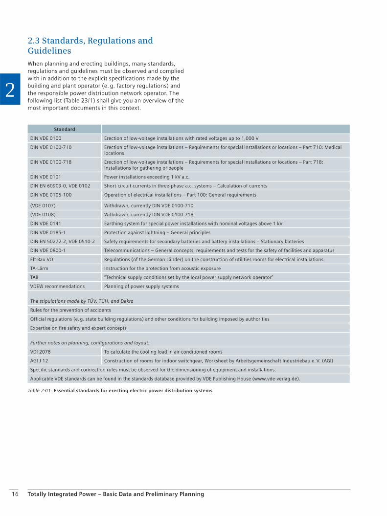
2.3 Standards, Regulations and GuidelinesWhen planning and erecting buildings, many standards, regulations and guidelines must be observed and complied with in addition to the explicit specifications made by the building and plant operator (e. g. factory regulations) and the responsible power distribution network operator. The following list (Table 23/1) shall give you an overview of the most important documents in this context.
Table 23/1: Essential standards for erecting electric power distribution systems
Standard
DIN VDE 0100 Erection of low-voltage installations with rated voltages up to 1,000 V
DIN VDE 0100-710 Erection of low-voltage installations – Requirements for special installations or locations – Part 710: Medical locations
DIN VDE 0100-718 Erection of low-voltage installations – Requirements for special installations or locations – Part 718: Installations for gathering of people
DIN VDE 0101 Power installations exceeding 1 kV a.c.
DIN EN 60909-0, VDE 0102 Short-circuit currents in three-phase a.c. systems – Calculation of currents
DIN VDE 0105-100 Operation of electrical installations – Part 100: General requirements
(VDE 0107) Withdrawn, currently DIN VDE 0100-710
(VDE 0108) Withdrawn, currently DIN VDE 0100-718
DIN VDE 0141 Earthing system for special power installations with nominal voltages above 1 kV
DIN VDE 0185-1 Protection against lightning – General principles
DIN EN 50272-2, VDE 0510-2 Safety requirements for secondary batteries and battery installations – Stationary batteries
DIN VDE 0800-1 Telecommunications – General concepts, requirements and tests for the safety of facilities and apparatus
Elt Bau VO Regulations (of the German Länder) on the construction of utilities rooms for electrical installations
TA-Lärm Instruction for the protection from acoustic exposure
TAB “Technical supply conditions set by the local power supply network operator”
VDEW recommendations Planning of power supply systems
The stipulations made by TÜV, TÜH, and Dekra
Rules for the prevention of accidents
Official regulations (e. g. state building regulations) and other conditions for building imposed by authorities
Expertise on fire safety and expert concepts
Further notes on planning, configurations and layout:
VDI 2078 To calculate the cooling load in air-conditioned rooms
AGI J 12 Construction of rooms for indoor switchgear, Worksheet by Arbeitsgemeinschaft Industriebau e. V. (AGI)
Specific standards and connection rules must be observed for the dimensioning of equipment and installations.
Applicable VDE standards can be found in the standards database provided by VDE Publishing House (www.vde-verlag.de).
17Totally Integrated Power – Basic Data and Preliminary Planning
2
2.4 Building Automation
2.4.1 Definition, Tasks and Benefit
Building automation (BA) comprises the equipment, soft-ware and services for automatic control, monitoring and optimization as well as operation and management of the technical installations in buildings.
Building automation calls on the data which are necessary for operating cost controlling, and also the documentation of an eco-audit system. A verification of undisturbed operation is possible. Maintenance-relevant data of the technical installations and appropriate statistics are avail-able in the building automation system. At the same time, building automation serves as a tool for management tasks such as the analysis, adjustment and continuous optimiza-tion of operating modes or for circumventing technical malfunctions.
A building automation system includes the following:
Field devices (detectors, encoders, switching devices and positioners, or sensors and actuators)
Local priority control units
Cabling, data networks and communication units
Control cabinets and automation stations or controllers
Management and server stations, dialog-oriented control units and peripheral equipment
Rights of use (licenses) for software
Services for the establishment of a BA system
System maintenance
2.4.2 Room Climate, Comfort and Health
In the Western world, people spend up to 95 % of their time in buildings. The quality of the the building climate is therefore of special importance for the health and well-be-ing of these people.
Building automation systems monitor, optimize and con-trol the products and systems of the individual installations such as heating, ventilation, air conditioning, lights and blinds control and thus provide an optimal climate in the building for the utmost of comfort.
2.4.3 Energy Performance and Environmental Friendliness
Building automation solutions with integrated energy services reduce energy consumption and operating cost and relieve the environment from CO2 pollution.
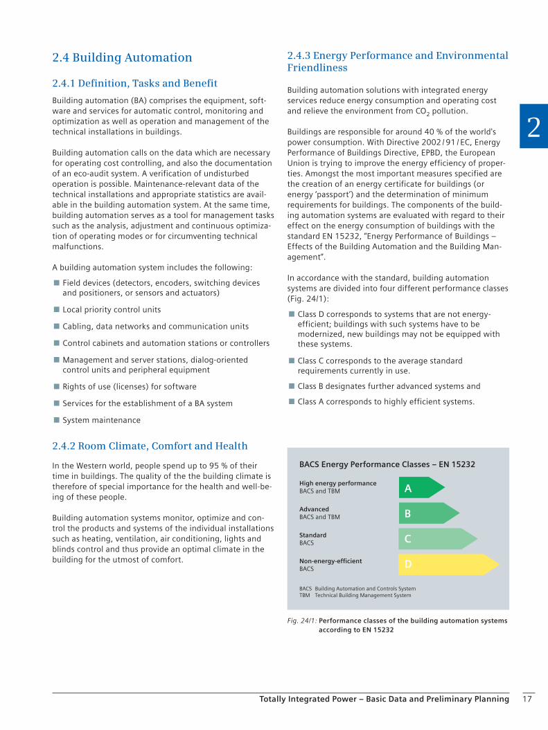
Buildings are responsible for around 40 % of the world's power consumption. With Directive 2002 / 91 / EC, Energy Performance of Buildings Directive, EPBD, the European Union is trying to improve the energy efficiency of proper-ties. Amongst the most important measures specified are the creation of an energy certificate for buildings (or energy ‘passport’) and the determination of minimum requirements for buildings. The components of the build-ing automation systems are evaluated with regard to their effect on the energy consumption of buildings with the standard EN 15232, “Energy Performance of Buildings – Effects of the Building Automation and the Building Man-agement”.
In accordance with the standard, building automation systems are divided into four different performance classes (Fig. 24/1):
Class D corresponds to systems that are not energy-efficient; buildings with such systems have to be modernized, new buildings may not be equipped with these systems.
Class C corresponds to the average standard requirements currently in use.
Class B designates further advanced systems and
Class A corresponds to highly efficient systems.
BACS Energy Performance Classes – EN 15232
High energy performanceBACS and TBM
Advanced BACS and TBM
StandardBACS
Non-energy-efficientBACS
BACS Building Automation and Controls SystemTBM Technical Building Management System
A
B
C
D
Fig. 24/1: Performance classes of the building automation systems according to EN 15232
18 Totally Integrated Power – Basic Data and Preliminary Planning
2
This standard also contains procedures for the calculation of energy performance by means of user profiles for build-ing types of varying complexity:
Offices
Hotels
Schools
Universities
Restaurants
Retail centers
Hospitals
Combinations of these standard elements provide clear specifications of how to achieve a certain performance class.
A modern building automation system fulfills the re-quirements of this standard in the highest performance classes (BACS performance class A or B). This specifically means that by the use of predefined energy saving functions in offices, for examples, up to 30% of the energy can be saved compared to the standard (BACS performance class C).
2.4.4 Protection of Investments across the Entire Building Lifecycle
A modern building automation system is a flexible and scalable system. It is suitable for projects of all sizes and complexities including the individual requirements of use for different building types. An end-to-end and consistent compatibility ensures decades of investment protection across the entire building lifecycle. Changes of use, expan-sions and modernizations can here be performed step by step.
2.5 Fire Protection and Security SystemsDanger management means the limitation and contain-ment of a host of different risks, it comprises the consis-tent treatment of the most diverse threatening events that may occur. This safeguards the protection of human be-ings, the security of material assets and the maintenance of operation within a building. The main task of danger management is the simple and safe treatment of critical alarms and events, as it is imperative to fight approaching danger immediately and with the best of means in order to prevent greater damage.
Danger management is typically associated with the spe-cific tasks of security systems, but it must also be extended to the potential hazards caused by any other technical installation.
Some examples are, for instance, the increase of tempera-ture and humidity in an air-conditioned room (e. g. in a museum), critical faults in the power distribution system (e. g. in a hospital), elevator alarms etc.
2.5.1 Fire Protection
Constructional measures alone are often not sufficient to prevent the initial ignition turning into a real fire. For this reason, effective fire protection is essential. Effective fire protection is in place when the following two conditions are satisfied: firstly, the fire must be detected quickly and clearly and signaled. And secondly, the correct measures must be implemented as quickly as possible. This is the only way to avoid direct fire and consequential damage or at least to keep this to a minimum.
Optimally coordinated fire detection, alarm, evacuation and fire extinguishing systems are more effective than separate solutions. The fire protection system can also be easily integrated with a management system in a larger security concept with intrusion protection (protection against the unauthorized intrusion of persons), access control and video surveillance. This creates a comprehen-sive danger management system.
Alarm and evacuation systems
Rapid evacuation saves lives. In addition to the prompt detection of the fire, quick and orderly evacuation of the building is of prime importance to save lives. Especially with regard to the changed court rulings on compensation claims, evacuation is playing an increasingly important role. In tall buildings such as hotels, banks or administra-tion buildings, or in buildings with a large number of visitors such as shopping centers, universities and cine-mas, efficient evacuation is of prime importance. The
19Totally Integrated Power – Basic Data and Preliminary Planning
2
following general rule applies: the faster the evacuation, the greater the chance of survival.
However, it is most important that panic does not break out amongst the users or residents of the building in an emergency. This is best achieved with reassuring informa-tion and clear instructions. It is therefore best when a fire alarm occurs that spoken messages are used for the evacu-ation. Spoken instructions via loudspeakers are clear, they are understood and followed. This greatly increases the chances for people to save themselves. For this reason, speech-controlled alarm systems are an ideal complement to fire alarm systems in all buildings.
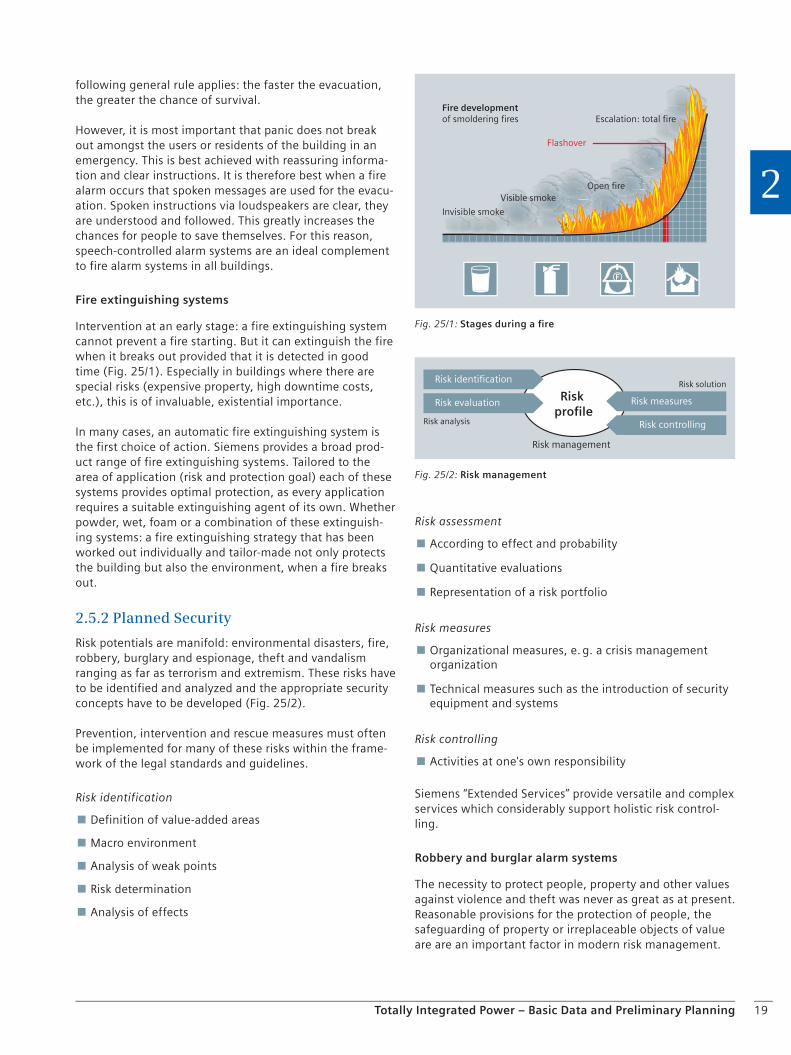
Fire extinguishing systems
Intervention at an early stage: a fire extinguishing system cannot prevent a fire starting. But it can extinguish the fire when it breaks out provided that it is detected in good time (Fig. 25/1). Especially in buildings where there are special risks (expensive property, high downtime costs, etc.), this is of invaluable, existential importance.
In many cases, an automatic fire extinguishing system is the first choice of action. Siemens provides a broad prod-uct range of fire extinguishing systems. Tailored to the area of application (risk and protection goal) each of these systems provides optimal protection, as every application requires a suitable extinguishing agent of its own. Whether powder, wet, foam or a combination of these extinguish-ing systems: a fire extinguishing strategy that has been worked out individually and tailor-made not only protects the building but also the environment, when a fire breaks out.
2.5.2 Planned Security
Risk potentials are manifold: environmental disasters, fire, robbery, burglary and espionage, theft and vandalism ranging as far as terrorism and extremism. These risks have to be identified and analyzed and the appropriate security concepts have to be developed (Fig. 25/2).
Prevention, intervention and rescue measures must often be implemented for many of these risks within the frame-work of the legal standards and guidelines.
Risk identification
Definition of value-added areas
Macro environment
Analysis of weak points
Risk determination
Analysis of effects
Risk assessment
According to effect and probability
Quantitative evaluations
Representation of a risk portfolio
Risk measures
Organizational measures, e. g. a crisis management organization
Technical measures such as the introduction of security equipment and systems
Risk controlling
Activities at one's own responsibility
Siemens “Extended Services” provide versatile and complex services which considerably support holistic risk control-ling.
Robbery and burglar alarm systems
The necessity to protect people, property and other values against violence and theft was never as great as at present. Reasonable provisions for the protection of people, the safeguarding of property or irreplaceable objects of value are are an important factor in modern risk management.
Fire developmentof smoldering fires
Flashover
Invisible smoke
Visible smoke
Escalation: total fire
Open fire
Fig. 25/1: Stages during a fi re
Risk identification
Risk evaluation
Risk analysis
Risk management
Risk measures
Risk controlling
Risk profile
Risk solution
Fig. 25/2: Risk management

20 Totally Integrated Power – Basic Data and Preliminary Planning
2
Four security aspects
Naivety and carelessness help burglars just as much as inadequate security measures. Therefore, protection must be both passive and active:
Passive by mechanical protection
Active using an electronic alarm system
Optimum protection of people and buildings is based on the following four pillars.
1. Prudence as free-of-charge protection
2. Mechanical protection equipment as the first line of defense
3. Electronic robbery and burglar alarm systems for the reliable detection of dangers
4. Forwarding of alarms for the immediate notification of personnel providing assistance.
Electronic robbery and burglar alarm systems
The decisive benefit of an alarm system is the protection against the established risks and the minimization or total prevention of injury to people or damage to property.
An electronic system has decisive advantages compared to purely mechanical protection measures. For example, it already detects the first attempt at a break-in and immedi-ately notifies the required security staff. With a purely mechanical building protection system, burglars, provided they can work unnoticed, could make any number of attempts to overcome the protection system. If you also consider that mechanical protection measures often can-not be used with modern building components, such as glass doors or special lightweight construction elements, then an active security system is frequently the only alter-native.
We recommend a sensible mixture of mechanical and electronic protection. The more time it takes to break in, the more time the notified security team has to intervene. The burglar also has much less time in the building, which can significantly reduce the possible damage.
Video surveillance systems
In sophisticated security concepts, the video system pro-vides the visual basis for decisions and thus plays a central role – in addition to the real-time monitoring of critical areas – in the identification of persons with the aid of biometric processes, and in the detection of dangers.
Stationary digital room surveillance
Stationary systems are used for specific room surveillance using the existing IT infrastructures. These systems detect changes and monitor various alarm zones. If an alarm is triggered, the video sequences are recorded digitally and forwarded to higher-level management systems.
Recording of alarm situations
Video surveillance detects incidents and documents the entire process when an incident occurs: from recording of the video images, transmission and storage of this infor-mation, initiation of automated measures through to centralized data evaluation and archiving.
Video control centers
Communication between the video system and the control center is performed using TCP / IP via any Ethernet, ATM or TN network structure. In conjunction with a Video Web Client, operation, control and access is possible from anywhere in the world.
Time management and access control systems
It must be possible to tailor access authorization and simultaneous authentification of persons to individual needs in a qualified and flexible manner. At the same time, access must be configured individually in terms of geo-graphical location and time.
These requirements can only be resolved with the aid of modern systems for access control. Open system solutions using flexible networks are configured under consideration of the intended use of the building and the organization. Special structures and specific workflows also have an impact. Factors such as the size of the company, the num-ber of people, doors, elevator and access gate control as well as additional functions also have to be taken into account.
Future-oriented solutions include not only the linking of business management applications, but also the integra-tion of other security systems. When linked to the building management systems, the information can also be opti-mally used under energy performance aspects.
21Totally Integrated Power – Basic Data and Preliminary Planning
2
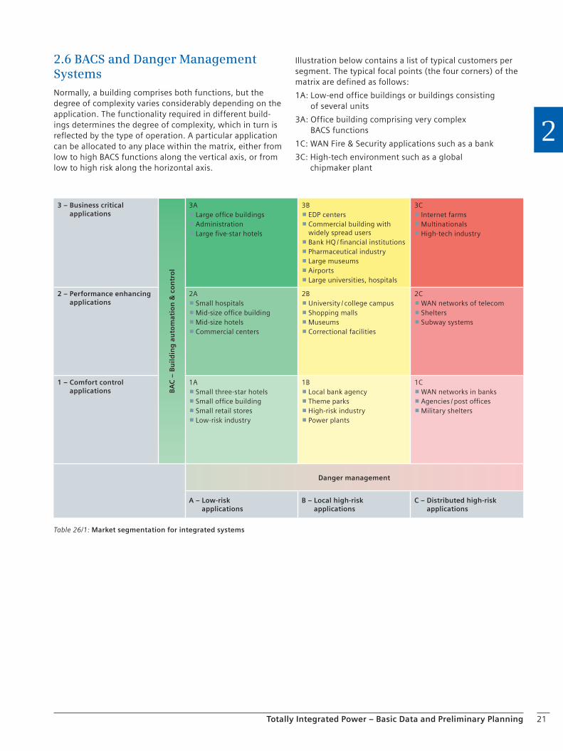
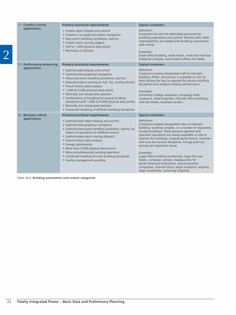
2.6 BACS and Danger Management SystemsNormally, a building comprises both functions, but the degree of complexity varies considerably depending on the application. The functionality required in different build-ings determines the degree of complexity, which in turn is reflected by the type of operation. A particular application can be allocated to any place within the matrix, either from low to high BACS functions along the vertical axis, or from low to high risk along the horizontal axis.
Illustration below contains a list of typical customers per segment. The typical focal points (the four corners) of the matrix are defined as follows:
1A: Low-end office buildings or buildings consisting of several units
3A: Office building comprising very complex BACS functions
1C: WAN Fire & Security applications such as a bank
3C: High-tech environment such as a global chipmaker plant
Table 26/1: Market segmentation for integrated systems
3 – Business critical applications
BA
C –
Bu
ild
ing
au
tom
atio
n &
co
ntr
ol
3A Large office buildings Administration Large five-star hotels
3B EDP centers Commercial building with widely spread users Bank HQ / financial institutions Pharmaceutical industry Large museums Airports Large universities, hospitals
3C Internet farms Multinationals High-tech industry
2 – Performance enhancing applications
2A Small hospitals Mid-size office building Mid-size hotels Commercial centers
2B University / college campus Shopping malls Museums Correctional facilities
2C WAN networks of telecom Shelters Subway systems
1 – Comfort control applications
1A Small three-star hotels Small office building Small retail stores Low-risk industry
1B Local bank agency Theme parks High-risk industry Power plants
1C WAN networks in banks Agencies / post offices Military shelters
Danger management
A – Low-risk applications
B – Local high-risk applications
C – Distributed high-risk applications
22 Totally Integrated Power – Basic Data and Preliminary Planning
2
Table 26/2: Building automation and control categories
1 – Comfort control applications
Primary functional requirements Typical customers
Simple object display and control Simple or no graphical system navigation Easy event handling (problems, alarms) Simple alarm routing (pager) 500 to 1,000 physical data points Normally no fulltime
Definition:Customers do not hire dedicated personnel for building automation and control. Persons with other responsibilities are tasked with building automation and control.
Examples:Small office building, small hotels, small and mid-size industrial complex, local branch offices for banks.
2 – Performance enhancing applications
Primary functional requirements Typical customers
Sophisticated display and control Sophisticated graphical navigation Advanced event handling (problems, alarms) Extended alarm routing (e-mail, fax, mobile phone) Trend / history data analysis 1,000 to 5,000 physical data points Normally one designated operator Combination of handling for several building disciplines with 1,000 to 5,000 physical data points
Normally one designated operator Combined handling of different building disciplines
Definition:Customers employ designated staff to maintain building. Often, one person is available on site (at least during the day) to operate the various building disciplines and analyze building performance.
Examples: University / college campuses, shopping malls, museums, small hospitals, mid-size office buildings, mid-size hotels, business centers.
3 – Business critical applications
Primary functional requirements Typical customers
Sophisticated object display and control Sophisticated graphical navigation Sophisticated event handling (problems, alarms) by means of specialists for different events
Sophisticated alarm routing dispatch Trend / history data analysis Energy optimization More than 5,000 physical data points Many simultaneously working operators Combined handling of most building disciplines Facility management possible
Definition:Customers employ designated crew to maintain building, building complex, or a number of separately located buildings. These persons (general and specialist operators) are always available on site to operate the buildings, analyze performance, maintain and tune the various disciplines. Energy and cost savings are important issues.
Examples:Large office building / authorities, large five-star hotels, computer centers, headquarters for banks / financial institutions, pharmaceutical companies, Internet farms, large museums, airports, large universities, university hospitals.
23Totally Integrated Power – Basic Data and Preliminary Planning
2
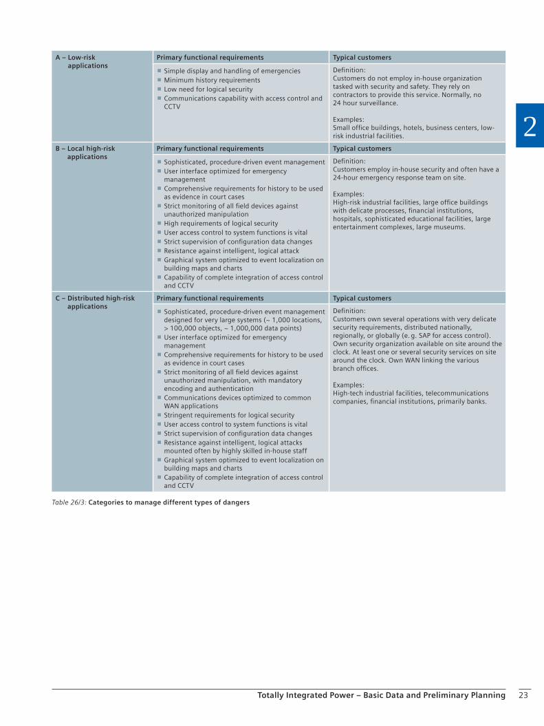
Table 26/3: Categories to manage different types of dangers
A – Low-risk applications
Primary functional requirements Typical customers
Simple display and handling of emergencies Minimum history requirements Low need for logical security Communications capability with access control and CCTV
Definition:Customers do not employ in-house organization tasked with security and safety. They rely on contractors to provide this service. Normally, no 24 hour surveillance.
Examples:Small office buildings, hotels, business centers, low-risk industrial facilities.
B – Local high-risk applications
Primary functional requirements Typical customers
Sophisticated, procedure-driven event management User interface optimized for emergency management
Comprehensive requirements for history to be used as evidence in court cases
Strict monitoring of all field devices against unauthorized manipulation
High requirements of logical security User access control to system functions is vital Strict supervision of configuration data changes Resistance against intelligent, logical attack Graphical system optimized to event localization on building maps and charts
Capability of complete integration of access control and CCTV
Definition:Customers employ in-house security and often have a 24-hour emergency response team on site.
Examples:High-risk industrial facilities, large office buildings with delicate processes, financial institutions, hospitals, sophisticated educational facilities, large entertainment complexes, large museums.
C – Distributed high-risk applications
Primary functional requirements Typical customers
Sophisticated, procedure-driven event management designed for very large systems (~ 1,000 locations, > 100,000 objects, ~ 1,000,000 data points)
User interface optimized for emergency management
Comprehensive requirements for history to be used as evidence in court cases
Strict monitoring of all field devices against unauthorized manipulation, with mandatory encoding and authentication
Communications devices optimized to common WAN applications
Stringent requirements for logical security User access control to system functions is vital Strict supervision of configuration data changes Resistance against intelligent, logical attacks mounted often by highly skilled in-house staff
Graphical system optimized to event localization on building maps and charts
Capability of complete integration of access control and CCTV
Definition:Customers own several operations with very delicate security requirements, distributed nationally, regionally, or globally (e. g. SAP for access control). Own security organization available on site around the clock. At least one or several security services on site around the clock. Own WAN linking the various branch offices.
Examples:High-tech industrial facilities, telecommunications companies, financial institutions, primarily banks.

24 Totally Integrated Power – Basic Data and Preliminary Planning
2

Chapter 3Determining and Splitting the Power Demand and Budget
26 Totally Integrated Power – Determining and Splitting the Power Demand and Budget
3
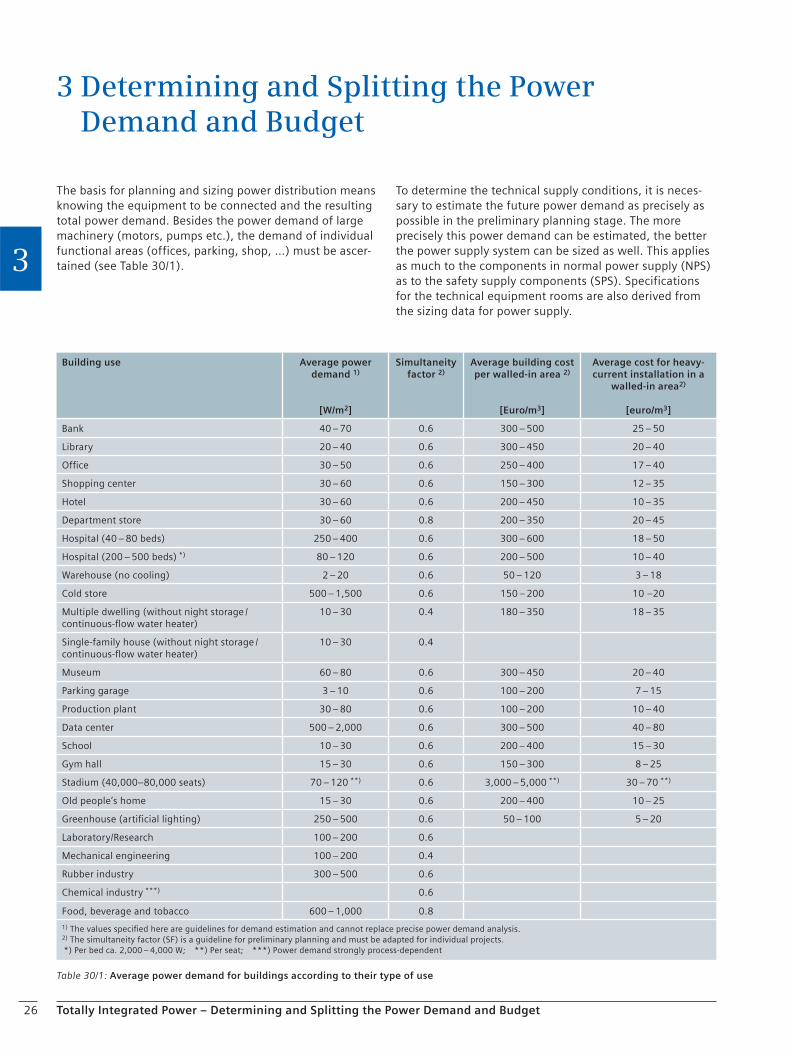
The basis for planning and sizing power distribution means knowing the equipment to be connected and the resulting total power demand. Besides the power demand of large machinery (motors, pumps etc.), the demand of individual functional areas (offices, parking, shop, …) must be ascer-tained (see Table 30/1).
3 Determining and Splitting the Power Demand and Budget
Table 30/1: Average power demand for buildings according to their type of use
Building use Average power demand 1)
[W/m2]
Simultaneity factor 2)
Average building cost per walled-in area 2)
[Euro/m3]
Average cost for heavy-current installation in a
walled-in area2)
[euro/m3]
Bank 40 – 70 0.6 300 – 500 25 – 50
Library 20 – 40 0.6 300 – 450 20 – 40
Office 30 – 50 0.6 250 – 400 17 – 40
Shopping center 30 – 60 0.6 150 – 300 12 – 35
Hotel 30 – 60 0.6 200 – 450 10 – 35
Department store 30 – 60 0.8 200 – 350 20 – 45
Hospital (40 – 80 beds) 250 – 400 0.6 300 – 600 18 – 50
Hospital (200 – 500 beds) *) 80 – 120 0.6 200 – 500 10 – 40
Warehouse (no cooling) 2 – 20 0.6 50 – 120 3 – 18
Cold store 500 – 1,500 0.6 150 – 200 10 –20
Multiple dwelling (without night storage /continuous-flow water heater)
10 – 30 0.4 180 – 350 18 – 35
Single-family house (without night storage /continuous-flow water heater)
10 – 30 0.4
Museum 60 – 80 0.6 300 – 450 20 – 40
Parking garage 3 – 10 0.6 100 – 200 7 – 15
Production plant 30 – 80 0.6 100 – 200 10 – 40
Data center 500 – 2,000 0.6 300 – 500 40 – 80
School 10 – 30 0.6 200 – 400 15 – 30
Gym hall 15 – 30 0.6 150 – 300 8 – 25
Stadium (40,000–80,000 seats) 70 – 120 **) 0.6 3,000 – 5,000 **) 30 – 70 **)
Old people’s home 15 – 30 0.6 200 – 400 10 – 25
Greenhouse (artificial lighting) 250 – 500 0.6 50 – 100 5 – 20
Laboratory/Research 100 – 200 0.6
Mechanical engineering 100 – 200 0.4
Rubber industry 300 – 500 0.6
Chemical industry ***) 0.6
Food, beverage and tobacco 600 – 1,000 0.8
1) The values specified here are guidelines for demand estimation and cannot replace precise power demand analysis.2) The simultaneity factor (SF) is a guideline for preliminary planning and must be adapted for individual projects. *) Per bed ca. 2,000 – 4,000 W; **) Per seat; ***) Power demand strongly process-dependent
To determine the technical supply conditions, it is neces-sary to estimate the future power demand as precisely as possible in the preliminary planning stage. The more precisely this power demand can be estimated, the better the power supply system can be sized as well. This applies as much to the components in normal power supply (NPS) as to the safety supply components (SPS). Specifications for the technical equipment rooms are also derived from the sizing data for power supply.
27Totally Integrated Power – Determining and Splitting the Power Demand and Budget
3
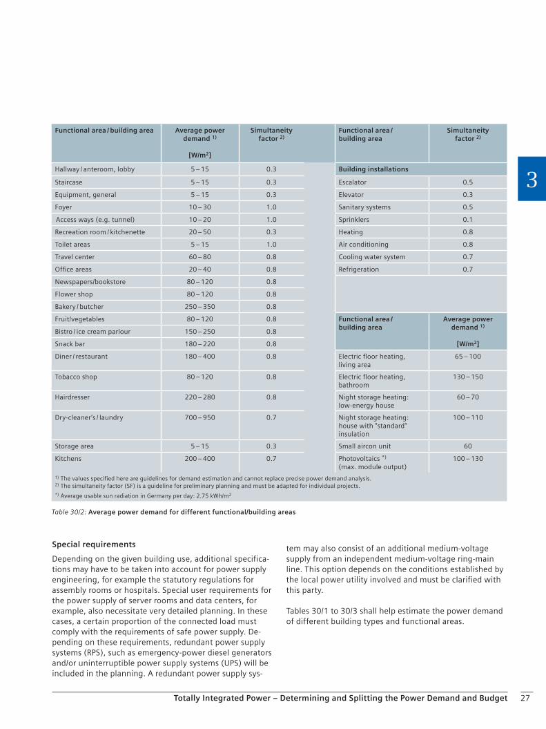
tem may also consist of an additional medium-voltage supply from an independent medium-voltage ring-main line. This option depends on the conditions established by the local power utility involved and must be clarified with this party.
Tables 30/1 to 30/3 shall help estimate the power demand of different building types and functional areas.
Special requirements
Depending on the given building use, additional specifica-tions may have to be taken into account for power supply engineering, for example the statutory regulations for assembly rooms or hospitals. Special user requirements for the power supply of server rooms and data centers, for example, also necessitate very detailed planning. In these cases, a certain proportion of the connected load must comply with the requirements of safe power supply. De-pending on these requirements, redundant power supply systems (RPS), such as emergency-power diesel generators and/or uninterruptible power supply systems (UPS) will be included in the planning. A redundant power supply sys-
Table 30/2: Average power demand for different functional/building areas
Functional area / building area Average power demand 1)
[W/m2]
Simultaneity factor 2)
Functional area /building area
Simultaneity factor 2)
Hallway / anteroom, lobby 5 – 15 0.3 Building installations
Staircase 5 – 15 0.3 Escalator 0.5
Equipment, general 5 – 15 0.3 Elevator 0.3
Foyer 10 – 30 1.0 Sanitary systems 0.5
Access ways (e.g. tunnel) 10 – 20 1.0 Sprinklers 0.1
Recreation room / kitchenette 20 – 50 0.3 Heating 0.8
Toilet areas 5 – 15 1.0 Air conditioning 0.8
Travel center 60 – 80 0.8 Cooling water system 0.7
Office areas 20 – 40 0.8 Refrigeration 0.7
Newspapers/bookstore 80 – 120 0.8
Flower shop 80 – 120 0.8
Bakery / butcher 250 – 350 0.8
Fruit/vegetables 80 – 120 0.8 Functional area /building area
Average power demand 1)
[W/m2]
Bistro / ice cream parlour 150 – 250 0.8
Snack bar 180 – 220 0.8
Diner / restaurant 180 – 400 0.8 Electric floor heating,living area
65 – 100
Tobacco shop 80 – 120 0.8 Electric floor heating, bathroom
130 – 150
Hairdresser 220 – 280 0.8 Night storage heating:low-energy house
60 – 70
Dry-cleaner’s / laundry 700 – 950 0.7 Night storage heating:house with "standard" insulation
100 – 110
Storage area 5 – 15 0.3 Small aircon unit 60
Kitchens 200 – 400 0.7 Photovoltaics *)
(max. module output)100 – 130
1) The values specified here are guidelines for demand estimation and cannot replace precise power demand analysis.2) The simultaneity factor (SF) is a guideline for preliminary planning and must be adapted for individual projects.*) Average usable sun radiation in Germany per day: 2.75 kWh/m2
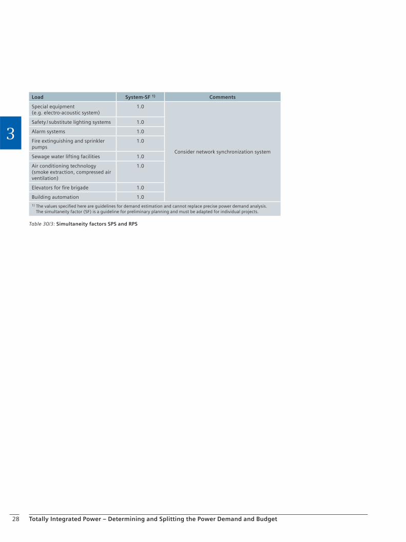
28 Totally Integrated Power – Determining and Splitting the Power Demand and Budget
3
Load System-SF 1) Comments
Special equipment (e.g. electro-acoustic system)
1.0
Consider network synchronization system
Safety / substitute lighting systems 1.0
Alarm systems 1.0
Fire extinguishing and sprinkler pumps
1.0
Sewage water lifting facilities 1.0
Air conditioning technology (smoke extraction, compressed air ventilation)
1.0
Elevators for fire brigade 1.0
Building automation 1.0
1) The values specified here are guidelines for demand estimation and cannot replace precise power demand analysis. The simultaneity factor (SF) is a guideline for preliminary planning and must be adapted for individual projects.
Table 30/3: Simultaneity factors SPS and RPS

29Totally Integrated Power – Determining and Splitting the Power Demand and Budget
3
Checklist for determining the power demand (in kW)
NPS SPS RPS UPS
Building (see Table 30/2) . . . . . . . . . . . . . . . . . . . .
. . . . . . . . . . . . . . . . . . . .
. . . . . . . . . . . . . . . . . . . .
. . . . . . . . . . . . . . . . . . . .
Functional area 1 . . . . . . . . . . . . . . . . . . . .
. . . . . . . . . . . . . . . . . . . .
. . . . . . . . . . . . . . . . . . . .
. . . . . . . . . . . . . . . . . . . .
Functional area 2 . . . . . . . . . . . . . . . . . . . .
. . . . . . . . . . . . . . . . . . . .
. . . . . . . . . . . . . . . . . . . .
. . . . . . . . . . . . . . . . . . . .
Functional area 3 . . . . . . . . . . . . . . . . . . . .
. . . . . . . . . . . . . . . . . . . .
. . . . . . . . . . . . . . . . . . . .
. . . . . . . . . . . . . . . . . . . .
Functional area 4 . . . . . . . . . . . . . . . . . . . .
. . . . . . . . . . . . . . . . . . . .
. . . . . . . . . . . . . . . . . . . .
. . . . . . . . . . . . . . . . . . . .
Functional area 5 . . . . . . . . . . . . . . . . . . . .
. . . . . . . . . . . . . . . . . . . .
. . . . . . . . . . . . . . . . . . . .
. . . . . . . . . . . . . . . . . . . .
Functional area 6 . . . . . . . . . . . . . . . . . . . .
. . . . . . . . . . . . . . . . . . . .
. . . . . . . . . . . . . . . . . . . .
. . . . . . . . . . . . . . . . . . . .
Functional area 7 . . . . . . . . . . . . . . . . . . . .
. . . . . . . . . . . . . . . . . . . .
. . . . . . . . . . . . . . . . . . . .
. . . . . . . . . . . . . . . . . . . .
Functional area 8 . . . . . . . . . . . . . . . . . . . .
. . . . . . . . . . . . . . . . . . . .
. . . . . . . . . . . . . . . . . . . .
. . . . . . . . . . . . . . . . . . . .
More loads (see Table 30/2)
NPS SPS RPS UPS
Heating . . . . . . . . . . . . . . . . . . . .
. . . . . . . . . . . . . . . . . . . .
. . . . . . . . . . . . . . . . . . . .
. . . . . . . . . . . . . . . . . . . .
Ventilation . . . . . . . . . . . . . . . . . . . .
. . . . . . . . . . . . . . . . . . . .
. . . . . . . . . . . . . . . . . . . .
. . . . . . . . . . . . . . . . . . . .
Air conditioning . . . . . . . . . . . . . . . . . . . .
. . . . . . . . . . . . . . . . . . . .
. . . . . . . . . . . . . . . . . . . .
. . . . . . . . . . . . . . . . . . . .
Sprinkler (incl. secondary pipe heating in cold area) . . . . . . . . . . . . . . . . . . . .
. . . . . . . . . . . . . . . . . . . .
. . . . . . . . . . . . . . . . . . . .
. . . . . . . . . . . . . . . . . . . .
Lifting systems for sewage water draining . . . . . . . . . . . . . . . . . . . .
. . . . . . . . . . . . . . . . . . . .
. . . . . . . . . . . . . . . . . . . .
. . . . . . . . . . . . . . . . . . . .
Safety lighting . . . . . . . . . . . . . . . . . . . .
. . . . . . . . . . . . . . . . . . . .
. . . . . . . . . . . . . . . . . . . .
. . . . . . . . . . . . . . . . . . . .
Elevators/escalators . . . . . . . . . . . . . . . . . . . .
. . . . . . . . . . . . . . . . . . . .
. . . . . . . . . . . . . . . . . . . .
. . . . . . . . . . . . . . . . . . . .
Fire alarm system . . . . . . . . . . . . . . . . . . . .
. . . . . . . . . . . . . . . . . . . .
. . . . . . . . . . . . . . . . . . . .
. . . . . . . . . . . . . . . . . . . .
Central control room for I&C and communications . . . . . . . . . . . . . . . . . . . .
. . . . . . . . . . . . . . . . . . . .
. . . . . . . . . . . . . . . . . . . .
. . . . . . . . . . . . . . . . . . . .
Public-address system . . . . . . . . . . . . . . . . . . . .
. . . . . . . . . . . . . . . . . . . .
. . . . . . . . . . . . . . . . . . . .
. . . . . . . . . . . . . . . . . . . .
Video surveillance / security system . . . . . . . . . . . . . . . . . . . .
. . . . . . . . . . . . . . . . . . . .
. . . . . . . . . . . . . . . . . . . .
. . . . . . . . . . . . . . . . . . . .
Other large equipment (tomographs (CT, MRT), pumps …) . . . . . . . . . . . . . . . . . . . .
. . . . . . . . . . . . . . . . . . . .
. . . . . . . . . . . . . . . . . . . .
. . . . . . . . . . . . . . . . . . . .
Checklist

30 Totally Integrated Power – Determining and Splitting the Power Demand and Budget
3
Chapter 4Power Distribution Planning in Commercial, Institutional and Industrial Buildings
4.1 Basics for Drafting Electrical Power Distribution Systems 30
4.2 Network Configurations and Supply Concepts 36
4.3 Power Supply with regard to Selectivity Evaluation (Examples) 54

32 Totally Integrated Power – Power Distribution Planning in Commercial, Institutional and Industrial Buildings
4
Distribution transformers (see section 5.2) Use low-loss transformers (operating costs)
Pay attention to noise emission (can be reduced e.g. by using low-loss transformers or a housing)
Take fire hazards and environmental impact into account (oil-immersed / cast-resin transformer)
Take the service life (partial discharge behavior) into account
Ensure sufficient ventilation
Dimensioning target: 80 % of the rated power
Check increase of performance by using forced air cooling (AF) (e.g. cross-flow ventilation for cast-resin transformers)
Low-voltage main distribution (see section 5.3) Observe degree of protection, heating, power loss, and required outgoing air (piping)
Observe specifications for busbar current and current breaking capacity (e.g. by reducing the main busbar trunking via an output-related panel arrangement)
Ensure safety of persons (only use factory-assembled, type-tested switchgear with arc fault testing)
Use standard / modular systems to ensure system expandability
Standardize built-in components, if possible, in order to minimize stockkeeping of spare parts and to be able to replace / swop devices in case of a fault (circuit-breakers, releases)
Assess requirements to flexibility / availability (fixed-mounted, plug-in, or withdrawable-unit design)
Consider the capability of the switchgear to communicate with a visualization system, if applicable (power management, operating states, switching functions)
Take increased safety requirements for accidental arcing into account (use design precautions that avoid grounding points which might provide a root for an accidental arc, inner compartmentalization, insulated busbars)
Type-tested incoming / outgoing feeders to busbar system (pay attention to room height)
Segmentation of busbar sections (take short-circuit current into account)
Use low-loss motors (take operating time into account)
Do not let motors and drives run idle unnecessarily (use load sensors)
4.1 Basics for Drafting Electrical Power Distribution SystemsWhen a power supply system is planned, there are some essential aspects which should be considered independent of the specific plant layout. Below you will find an overview of the whole power supply system across all planning stages.
General Involve the responsible experts / public authorities / inspection and testing bodies in the concept at an early stage Pay attention to efficiency aspects, the safety of persons as well as the availability / reliability of the power supply Determine the system / supply concept Use tested technology (inspection and testing protocols, references …) Pay attention to the system integration of individual components, spare parts management (stockkeeping), service and warranties (choose the components for the entire power supply system from one supplier, if possible) Determine and document the power balance, voltage drop, conditions for disconnection from supply, selectivity together with the selection of components Room layout (e.g. room size, room height, air conditioning, operator aisles, escape routes) Check access routes and on site conditions for moving (parts of) the installation into place (ceiling loads, doors, hoisting gear) Observe fire protection requirements Observe EMC considerations when selecting components Observe the requirements of DIN EN 15232 (building energy efficiency)
Medium-voltage switchgear (see section 5.1) Observe the technical supply conditions and implementation guidelines of the local power supply network operator and announce the power demand at an early stage Observe specifications for nominal voltage, busbar currents and breaking capacities Use no-maintenance / low-maintenance technology Observe specifications for room heights according to arcing fault tests Make provisions for a pressure relief in the switchgear room in case of a fault; check via calculation, if necessary Consider expandability options for the switchgear at minimum time expense (modular systems)
4 Power Distribution Planning in Commercial, Institutional and Industrial Buildings

33Totally Integrated Power – Power Distribution Planning in Commercial, Institutional and Industrial Buildings
4
Provide variable-speed drives for systems with varying loads (power saving)
Take regenerative feedback from large drives into account in the event of a short circuit (increased short-circuit load on the network)
Take the impact of harmonic content from variable-speed drives into account
Choose a manufacturer that provides an integrated, well coordinated range of products (selectivity, interfaces, service, maintenance)
Use modular systems (e.g. circuit-breakers: same accessories for different sizes)
Use communication-capable devices with standardized bus systems (interfacing to the protection and control system etc.)
Circuit-breaker-protected / fuse-protected technology
Busbar trunking system (see section 5.4) Observe current carrying capacity in view of mounting position / ambient temperature / degree of protection
Select suitable protective device for the busbar system (current carrying capacity, overcurrent and short-circuit protection)
Use type-tested products (type test for busbar, busbar / distribution)
Maintain a system approach throughout (connection of transformer to LVMD, LVMD to sub-distribution, busbar trunking system …)
Consider fire loads (busbar / cable)
Make sure that busbars / cables are made of halogen-free materials
Distribution boards (see section 5.5) Use type-tested products (TTA)
Choose flexible and integrated, well matched products (flush-mounting, surface-mounting, same accessories)
Observe permissible power loss
Determine / check safety class (1 or 2)
Choose an integrated, well coordinated product range (uniform design / mounting heights / grid dimensions for communication units and switchgear / controlgear units
Have interfacing options to the central building control system been provided / desired?
UPS (see section 5.8) Input network (power supply system, supply quality (voltage, harmonics, frequency, short interruption), power factor)
System perturbations to the input network by UPS (6- ,12-pulse, IGBT rectifier, filter)
Load on safe busbar; scheduled reserve for rated power, power factor, crest factor
Parallel connection; centrally operated, manual bypass
for servicing
Power factor of the connected loads
Battery / centrifugal mass: bridging time, service life,
maintenance, location
Ventilation, air conditioning, cable sizing
Communication link and shutdown functionality
Central control system / power management
(see section 6)
Define requirements to the central control system (safe
switching, secure data transfer)
Define power measuring points (in coordination with
the operator)
Use standardized bus systems / communications
(communication with other technologies)
Limit the number of bus systems to an absolute
minimum (interfaces are expensive, linking systems
might be problematic)
Choose a visualization system with common interfaces
(e.g. AS-i, KNX, PROFIBUS, Ethernet)
Prefer systems that use standard modules (cost
minimization)
Choose systems from manufacturers providing a good
service network (availability)
Avoid systems offering only a narrow range of
applications
Take data volumes and transmission rates into account
for your choice of a system
Overvoltage protection (e.g. use optical waveguides for
outdoor installations)
Use expandable / upgradeable systems (supplementation
with a power management system)
Lighting (see section 10)
Use automatic lighting controls (time / daylight / room
and workplace occupancy detection)
Use power-saving fluorescent lamps with electronic
starters / controlgear (dimmable ECG)
Use highly efficient reflectors
Check and adapt light intensity stipulations for certain
functional areas
Standby power supply (see section 5.9)
Rating of the units according to use (safety / standby
power supply)
Separate room layout (fuel storage, air intake and outlet
system, exhaust system, etc.)
Requirements to the switchgear (e.g. parallel, stand-
alone, or isolated operation)
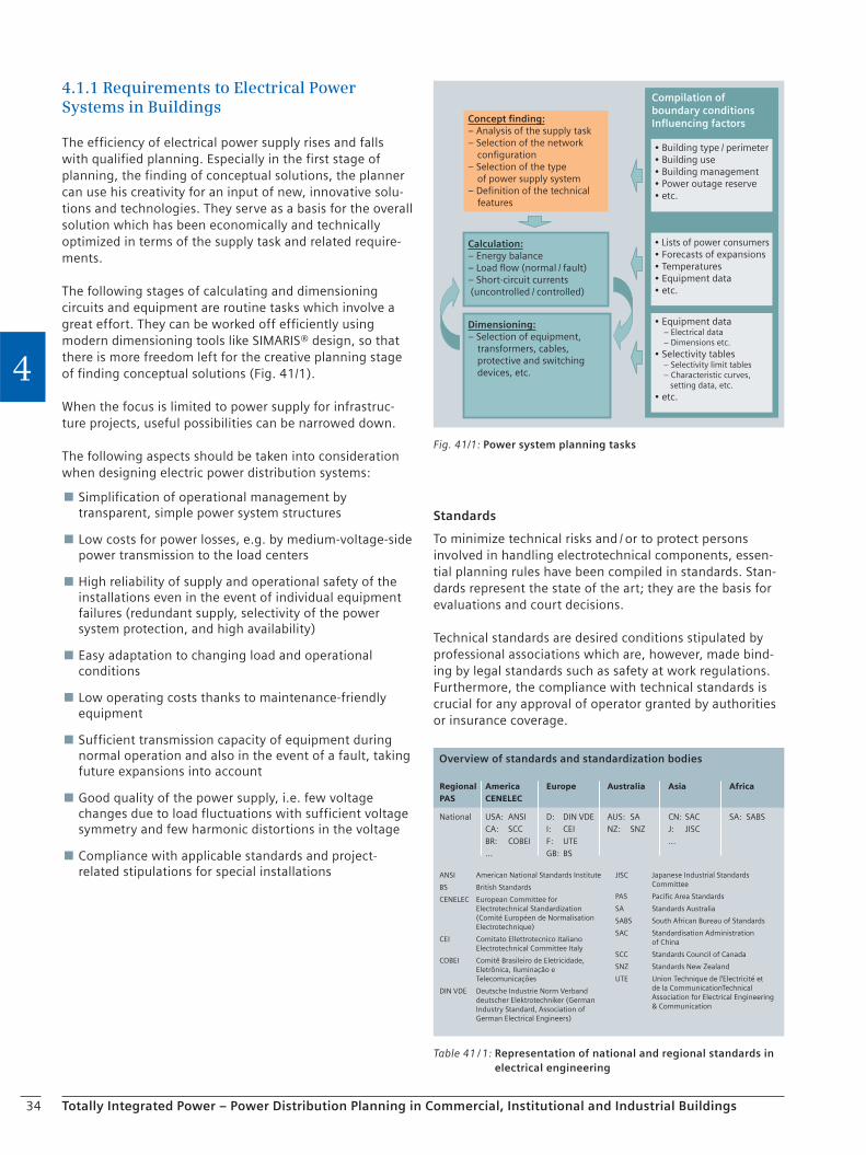
34 Totally Integrated Power – Power Distribution Planning in Commercial, Institutional and Industrial Buildings
4
Standards
To minimize technical risks and / or to protect persons involved in handling electrotechnical components, essen-tial planning rules have been compiled in standards. Stan-dards represent the state of the art; they are the basis for evaluations and court decisions.
Technical standards are desired conditions stipulated by professional associations which are, however, made bind-ing by legal standards such as safety at work regulations. Furthermore, the compliance with technical standards is crucial for any approval of operator granted by authorities or insurance coverage.
4.1.1 Requirements to Electrical Power Systems in Buildings
The efficiency of electrical power supply rises and falls with qualified planning. Especially in the first stage of planning, the finding of conceptual solutions, the planner can use his creativity for an input of new, innovative solu-tions and technologies. They serve as a basis for the overall solution which has been economically and technically optimized in terms of the supply task and related require-ments.
The following stages of calculating and dimensioning circuits and equipment are routine tasks which involve a great effort. They can be worked off efficiently using modern dimensioning tools like SIMARIS® design, so that there is more freedom left for the creative planning stage of finding conceptual solutions (Fig. 41/1).
When the focus is limited to power supply for infrastruc-ture projects, useful possibilities can be narrowed down.
The following aspects should be taken into consideration when designing electric power distribution systems:
Simplification of operational management by transparent, simple power system structures
Low costs for power losses, e.g. by medium-voltage-side power transmission to the load centers
High reliability of supply and operational safety of the installations even in the event of individual equipment failures (redundant supply, selectivity of the power system protection, and high availability)
Easy adaptation to changing load and operational conditions
Low operating costs thanks to maintenance-friendly equipment
Sufficient transmission capacity of equipment during normal operation and also in the event of a fault, taking future expansions into account
Good quality of the power supply, i.e. few voltage changes due to load fluctuations with sufficient voltage symmetry and few harmonic distortions in the voltage
Compliance with applicable standards and project-related stipulations for special installations
Table 41 / 1: Representation of national and regional standards in electrical engineering
Regional America Europe Australia Asia Africa PAS CENELEC
National USA: ANSI D: DIN VDE AUS: SA CN: SAC SA: SABS CA: SCC I: CEI NZ: SNZ J: JISC BR: COBEI F: UTE … ... GB: BS
ANSI American National Standards Institute
BS British Standards
CENELEC European Committee for Electrotechnical Standardization (Comité Européen de Normalisation Electrotechnique)
CEI Comitato Ellettrotecnico Italiano Electrotechnical Committee Italy
COBEI Comitê Brasileiro de Eletricidade, Eletrônica, Iluminação e Telecomunicações
DIN VDE Deutsche Industrie Norm Verband deutscher Elektrotechniker (German Industry Standard, Association of German Electrical Engineers)
JISC Japanese Industrial Standards Committee
PAS Pacific Area Standards
SA Standards Australia
SABS South African Bureau of Standards
SAC Standardisation Administration of China
SCC Standards Council of Canada
SNZ Standards New Zealand
UTE Union Technique de l’Electricité et de la CommunicationTechnical Association for Electrical Engineering & Communication
Overview of standards and standardization bodies
Fig. 41/1: Power system planning tasks
Concept finding:– Analysis of the supply task– Selection of the network configuration– Selection of the type of power supply system– Definition of the technical features
Calculation:– Energy balance– Load flow (normal / fault)– Short-circuit currents (uncontrolled / controlled)
Dimensioning:– Selection of equipment, transformers, cables,
– Electrical data – Dimensions etc.
setting data, etc.
Compilation of boundary conditionsInfluencing factors
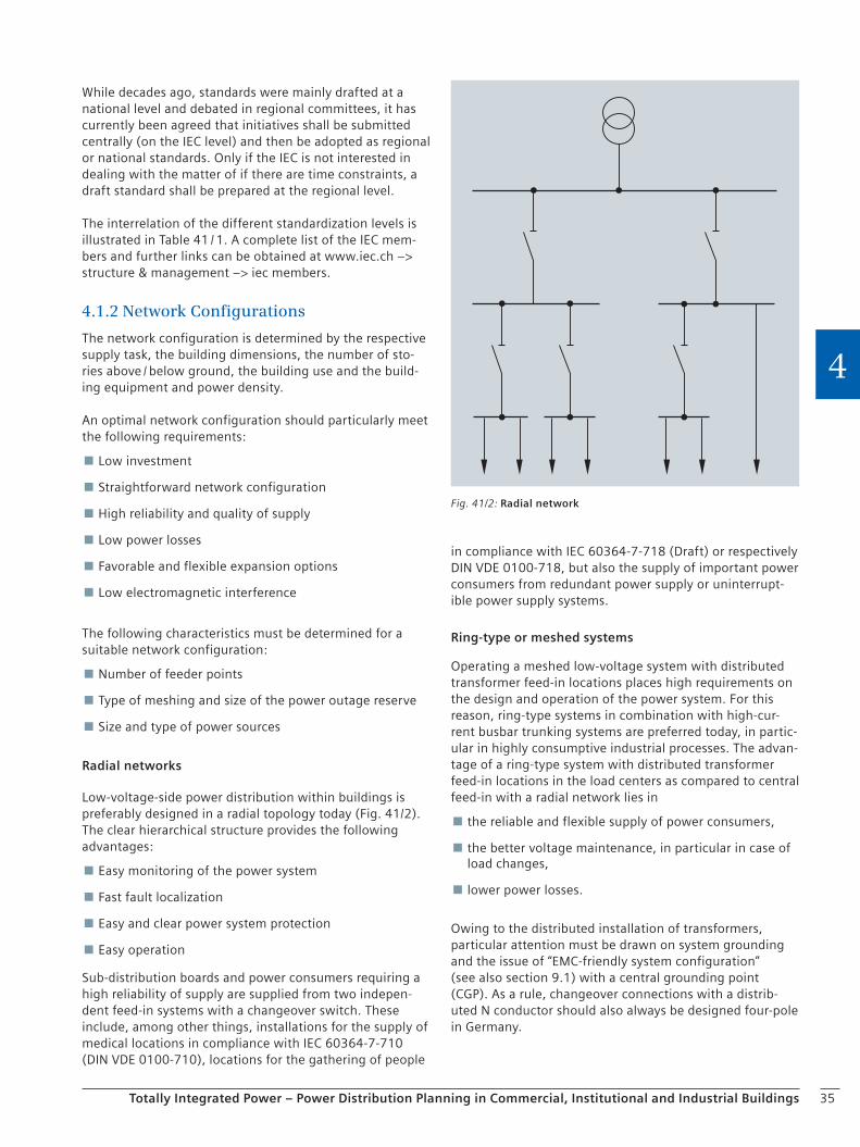
35Totally Integrated Power – Power Distribution Planning in Commercial, Institutional and Industrial Buildings
4
While decades ago, standards were mainly drafted at a national level and debated in regional committees, it has currently been agreed that initiatives shall be submitted centrally (on the IEC level) and then be adopted as regional or national standards. Only if the IEC is not interested in dealing with the matter of if there are time constraints, a draft standard shall be prepared at the regional level.
The interrelation of the different standardization levels is illustrated in Table 41 / 1. A complete list of the IEC mem-bers and further links can be obtained at www.iec.ch –> structure & management –> iec members.
4.1.2 Network Configurations
The network configuration is determined by the respective supply task, the building dimensions, the number of sto-ries above / below ground, the building use and the build-ing equipment and power density.
An optimal network configuration should particularly meet the following requirements:
Low investment
Straightforward network configuration
High reliability and quality of supply
Low power losses
Favorable and flexible expansion options
Low electromagnetic interference
The following characteristics must be determined for a suitable network configuration:
Number of feeder points
Type of meshing and size of the power outage reserve
Size and type of power sources
Radial networks
Low-voltage-side power distribution within buildings is preferably designed in a radial topology today (Fig. 41/2). The clear hierarchical structure provides the following advantages:
Easy monitoring of the power system
Fast fault localization
Easy and clear power system protection
Easy operation
Sub-distribution boards and power consumers requiring a high reliability of supply are supplied from two indepen-dent feed-in systems with a changeover switch. These include, among other things, installations for the supply of medical locations in compliance with IEC 60364-7-710 (DIN VDE 0100-710), locations for the gathering of people
in compliance with IEC 60364-7-718 (Draft) or respectively DIN VDE 0100-718, but also the supply of important power consumers from redundant power supply or uninterrupt-ible power supply systems.
Ring-type or meshed systems
Operating a meshed low-voltage system with distributed transformer feed-in locations places high requirements on the design and operation of the power system. For this reason, ring-type systems in combination with high-cur-rent busbar trunking systems are preferred today, in partic-ular in highly consumptive industrial processes. The advan-tage of a ring-type system with distributed transformer feed-in locations in the load centers as compared to central feed-in with a radial network lies in
the reliable and flexible supply of power consumers,
the better voltage maintenance, in particular in case of load changes,
lower power losses.
Owing to the distributed installation of transformers, particular attention must be drawn on system grounding and the issue of “EMC-friendly system configuration” (see also section 9.1) with a central grounding point (CGP). As a rule, changeover connections with a distrib-uted N conductor should also always be designed four-pole in Germany.
Fig. 41/2: Radial network
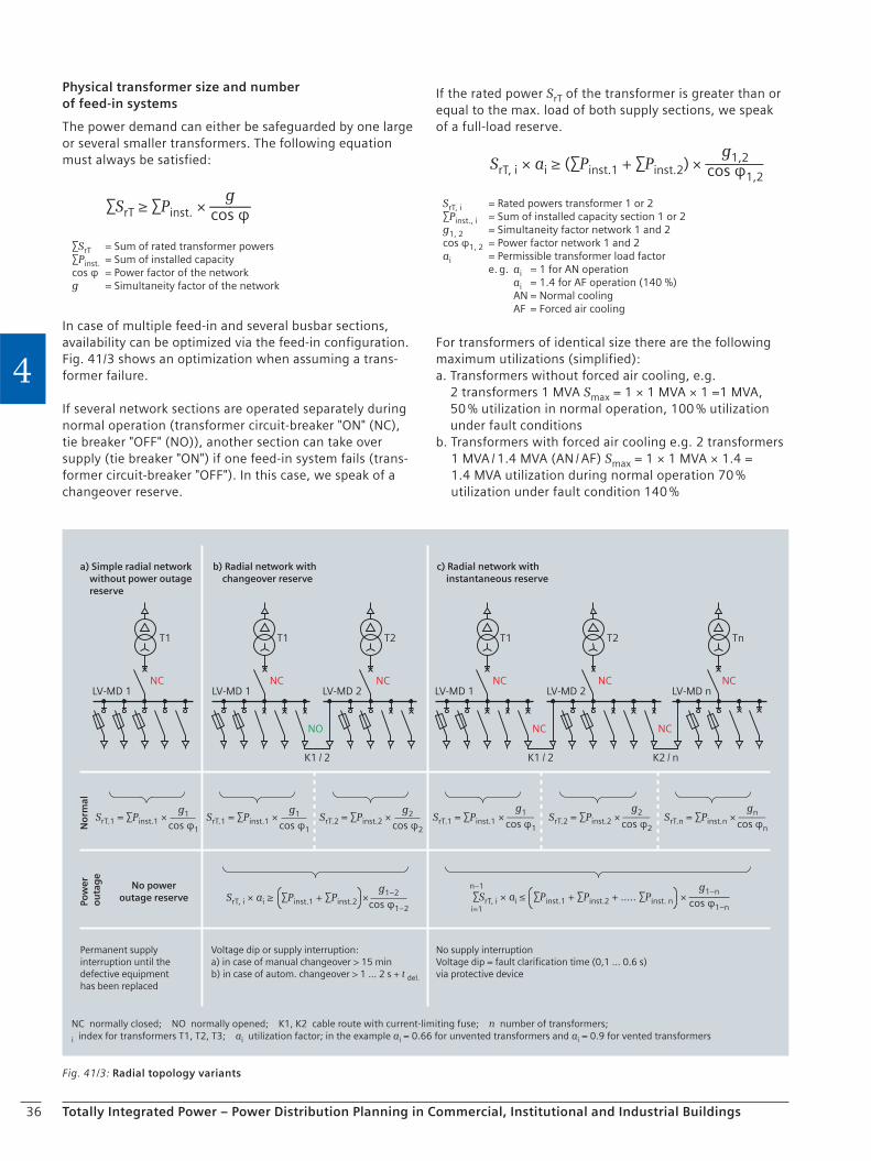
36 Totally Integrated Power – Power Distribution Planning in Commercial, Institutional and Industrial Buildings
4
Physical transformer size and number of feed-in systems
The power demand can either be safeguarded by one large or several smaller transformers. The following equation must always be satisfied:
gcos φ∑SrT ≥ ∑Pinst. × ――
∑SrT = Sum of rated transformer powers∑Pinst. = Sum of installed capacitycos φ = Power factor of the networkg = Simultaneity factor of the network
In case of multiple feed-in and several busbar sections, availability can be optimized via the feed-in configuration. Fig. 41/3 shows an optimization when assuming a trans-former failure.
If several network sections are operated separately during normal operation (transformer circuit-breaker "ON" (NC), tie breaker "OFF" (NO)), another section can take over supply (tie breaker "ON") if one feed-in system fails (trans-former circuit-breaker "OFF"). In this case, we speak of a changeover reserve.
If the rated power SrT of the transformer is greater than or equal to the max. load of both supply sections, we speak of a full-load reserve.
g1,2cos φ1,2
SrT, i × ai ≥ (∑Pinst.1 + ∑Pinst.2) × ―――
SrT, i = Rated powers transformer 1 or 2∑Pinst., i = Sum of installed capacity section 1 or 2 g1, 2 = Simultaneity factor network 1 and 2cos φ1, 2 = Power factor network 1 and 2ai = Permissible transformer load factor e. g. ai = 1 for AN operation
ai = 1.4 for AF operation (140 %) AN = Normal cooling AF = Forced air cooling
For transformers of identical size there are the following maximum utilizations (simplified):a. Transformers without forced air cooling, e.g.
2 transformers 1 MVA Smax = 1 × 1 MVA × 1 =1 MVA, 50 % utilization in normal operation, 100 % utilization under fault conditions
b. Transformers with forced air cooling e.g. 2 transformers 1 MVA / 1.4 MVA (AN / AF) Smax = 1 × 1 MVA × 1.4 = 1.4 MVA utilization during normal operation 70 % utilization under fault condition 140 %
Fig. 41/3: Radial topology variants
NC normally closed; NO normally opened; K1, K2 cable route with current-limiting fuse; n number of transformers;
i index for transformers T1, T2, T3; ai utilization factor; in the example ai = 0.66 for unvented transformers and ai = 0.9 for vented transformers
No power outage reservePo
wer
o
uta
ge
No
rmal
Permanent supply interruption until the defective equipment has been replaced
Voltage dip or supply interruption:a) in case of manual changeover > 15 minb) in case of autom. changeover > 1 ... 2 s + t del.
No supply interruptionVoltage dip = fault clarification time (0,1 ... 0.6 s)via protective device
a) Simple radial network without power outage reserve
b) Radial network with changeover reserve
c) Radial network with instantaneous reserve
LV-MD 1 LV-MD 2LV-MD 1
K1 / 2
LV-MD 2 LV-MD nLV-MD 1
K1 / 2 K2 / n
T1 T1 T2 T1 T2 Tn
NC NCNC
NO
NC
NC
NCNC
NC
g1
cos φ1
SrT.1 = ∑Pinst.1 × g1
cos φ1
SrT.1 = ∑Pinst.1 × g2
cos φ2
SrT.2 = ∑Pinst.2 × g1
cos φ1SrT.1 = ∑Pinst.1 × ――
g2
cos φ2SrT.2 = ∑Pinst.2 × ――
gn
cos φnSrT.n = ∑Pinst.n × ――
n–1
i=1 ∑SrT, i × ai ≤ ∑Pinst.1 + ∑Pinst.2 + ….. ∑Pinst. n × ―――
g1–n
cos φ1–n
g1–2
cos φ1–2SrT, i × ai ≥ ∑Pinst.1 + ∑Pinst.2 ×
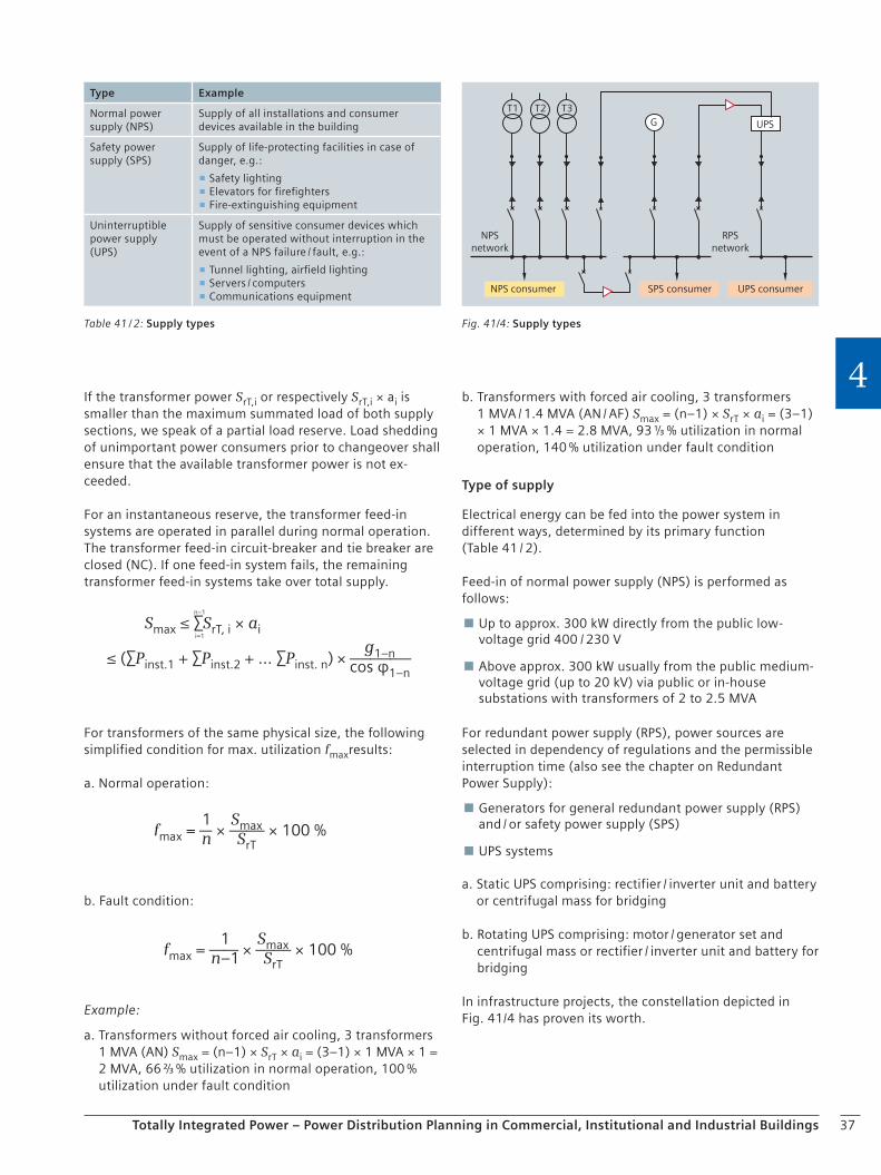
37Totally Integrated Power – Power Distribution Planning in Commercial, Institutional and Industrial Buildings
4If the transformer power SrT,i or respectively SrT,i × ai is smaller than the maximum summated load of both supply sections, we speak of a partial load reserve. Load shedding of unimportant power consumers prior to changeover shall ensure that the available transformer power is not ex-ceeded.
For an instantaneous reserve, the transformer feed-in systems are operated in parallel during normal operation. The transformer feed-in circuit-breaker and tie breaker are closed (NC). If one feed-in system fails, the remaining transformer feed-in systems take over total supply.
n–1
i=1
Smax ≤ ∑SrT, i × ai
g1–ncos φ1–n
≤ (∑Pinst.1 + ∑Pinst.2 + … ∑Pinst. n) × ―――
For transformers of the same physical size, the following simplified condition for max. utilization fmaxresults:
a. Normal operation:
1nfmax = ― × ―― × 100 %
SmaxSrT
b. Fault condition:
1n–1fmax = ―― × ―― × 100 %
SmaxSrT
Example:
a. Transformers without forced air cooling, 3 transformers 1 MVA (AN) Smax = (n–1) × SrT × ai = (3–1) × 1 MVA × 1 = 2 MVA, 66 ⅔ % utilization in normal operation, 100 % utilization under fault condition
b. Transformers with forced air cooling, 3 transformers 1 MVA / 1.4 MVA (AN / AF) Smax = (n–1) × SrT × ai = (3–1) × 1 MVA × 1.4 = 2.8 MVA, 93 ⅓ % utilization in normal operation, 140 % utilization under fault condition
Type of supply
Electrical energy can be fed into the power system in different ways, determined by its primary function (Table 41 / 2).
Feed-in of normal power supply (NPS) is performed as follows:
Up to approx. 300 kW directly from the public low-voltage grid 400 / 230 V
Above approx. 300 kW usually from the public medium-voltage grid (up to 20 kV) via public or in-house substations with transformers of 2 to 2.5 MVA
For redundant power supply (RPS), power sources are selected in dependency of regulations and the permissible interruption time (also see the chapter on Redundant Power Supply):
Generators for general redundant power supply (RPS) and / or safety power supply (SPS)
UPS systems
a. Static UPS comprising: rectifier / inverter unit and battery or centrifugal mass for bridging
b. Rotating UPS comprising: motor / generator set and centrifugal mass or rectifier / inverter unit and battery for bridging
In infrastructure projects, the constellation depicted in Fig. 41/4 has proven its worth.
NPSnetwork
RPSnetwork
UPS consumerSPS consumerNPS consumer
UPS
T1 T2 T3G
Fig. 41/4: Supply typesTable 41 / 2: Supply types
Type Example
Normal power supply (NPS)
Supply of all installations and consumer devices available in the building
Safety power supply (SPS)
Supply of life-protecting facilities in case of danger, e.g.:
Safety lighting Elevators for firefighters Fire-extinguishing equipment
Uninterruptible power supply (UPS)
Supply of sensitive consumer devices which must be operated without interruption in the event of a NPS failure / fault, e.g.:
Tunnel lighting, airfield lighting Servers / computers Communications equipment

38 Totally Integrated Power – Power Distribution Planning in Commercial, Institutional and Industrial Buildings
4
4.2 Network Configurations and Power Supply Concepts
4.2.1 Power Supply Systems
Electric power systems are distinguished as follows:
Type of current used:
DC; AC ~ 50 Hz –
Type and number of live conductors within the system, e.g.:
Three-phase 4-wire (L1, L2, L3, N) –
Three-phase 3-wire (L1, L2, L3) –
Single-phase 2-wire (L1, N) –
Two-phase 2-wire (L1, L2), etc. –
Note! In accordance with DIN VDE 0100-200 Section 826-12-08, the PE conductor is not a live conductor.
Type of connection to ground of the system:
Low-voltage systems: IT, TT, TN – Medium-voltage systems: isolated, low-resistance, –compensated
The type of connection to ground of the medium-voltage or low-voltage system (Fig. 42/1) must be selected care-fully, as it has a major impact on the expense required for protective measures. It also determines electromagnetic compatibility regarding the low-voltage system.
From experience, the best cost-benefit ratio for electric systems within the normal power supply is achieved with the TN-S system at the low-voltage level.
Fig. 42/1: Systems according to type of connection to ground in acc. with ICE 60364-3 (DIN VDE 0100-300) Section 312.2
TN system: In the TN system, one operating line is directly grounded; the exposed conductive parts in the electrical installation are connected to this grounded point via protective conductors. Dependent on the arrangement of the protective (PE) and neutral (NE) conductors, three types are distinguished:
TT system: In the TT system, one operating line is directly grounded; the exposed conductive parts in the electrical installation are connected to grounding electrodes which are electrically independent of the grounding electrode of the system.
IT system: In the IT system, all active operating lines are separated from ground or one point is is connected to ground via an impedance.
First letter = grounding condition of the supplying power sourceT = direct grounding of one point (live conductor)I = no point (live conductor) or one point of the power source is connected to ground via an impedance
Second letter = grounding condition of the exposed conductive parts in the electrical installationT = exposed conductive parts are connected to ground separately, in groups or jointlyN = exposed conductive parts are directly connected to the grounded point of the electrical installation (usually N conductor close to the power source) via protective conductors
Further letters = arrangement of the neutral conductor and protective conductorS = neutral conductor function and protective conductor function are laid in separate conductors.C = neutral conductor function and protective conductor function are laid in one conductor (PEN).
Power source
Electrical installation
a) TN-S system: In the entire system, neutral (N) and protective (PE) conductors are laid separately.
b) TN-C system: In the entire system, the functions of the neutral and protective conductor are combined in one conductor (PEN).
c) TN-C-S system: In a part of the system, the functions of the neutral and protective conductor are combined in one conductor (PEN).
Power source Electrical installation
Power source
Electrical installationPower source
Electrical installation
Power source Electrical installation
1
2
3
4
Exposed conductive part
High-resistance impedance
Operational or system grounding RB
Grounding of exposed conductive parts RA (separately, in groups or jointly)
L1
N
L2L3
PE
13
1 13
1 13
1
L1
PEN
L2L3
L1
PEN PEN
L2L3
13 4 1
2
3 4
L1
N
L2L3
RB RA
L1
N
L2L3
RB RA
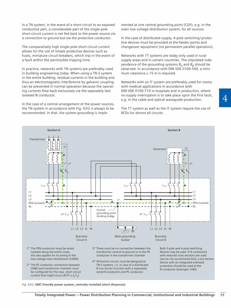
39Totally Integrated Power – Power Distribution Planning in Commercial, Institutional and Industrial Buildings
4
In a TN system, in the event of a short-circuit to an exposed conductive part, a considerable part of the single-pole short-circuit current is not fed back to the power source via a connection to ground but via the protective conductor.
The comparatively high single-pole short-circuit current allows for the use of simple protective devices such as fuses, miniature circuit-breakers, which trip in the event of a fault within the permissible tripping time.
In practice, networks with TN systems are preferably used in building engineering today. When using a TN-S system in the entire building, residual currents in the building and thus an electromagnetic interference by galvanic coupling can be prevented in normal operation because the operat-ing currents flow back exclusively via the separately laid isolated N conductor.
In the case of a central arrangement of the power sources, the TN system in accordance with Fig. 42/2 is always to be recommended. In that, the system grounding is imple-
mented at one central grounding point (CGP), e.g. in the main low-voltage distribution system, for all sources.
In the case of distributed supply, 4-pole switching / protec-tive devices must be provided at the feeder points and changeover equipment (no permanent parallel operation).
Networks with TT systems are today only used in rural supply areas and in certain countries. The stipulated inde-pendence of the grounding systems RA and RB should be observed. In accordance with DIN VDE 0100-540, a mini-mum clearance ≥ 15 m is required.
Networks with an IT system are preferably used for rooms with medical applications in accordance with DIN VDE 0100-710 in hospitals and in production, where no supply interruption is to take place upon the first fault, e.g. in the cable and optical waveguide production.
The TT system as well as the IT system require the use of RCDs for almost all circuits.
Fig. 42/2: EMC-friendly power system, centrally installed (short distances)
L1L2L3PEN (isolated)
PE
All branch circuits must be designed asTN-S systems, i.e. in case of a distributedN con-ductor function with a separatelywired N conductor and PE conductor.
Both 3-pole and 4-pole switchingdevices may be used. If N conductorswith reduced cross sections are used(we do not recommend this), a pro-tectivedevice with an integrated overloadprotection should be used at theN conductor (example: LSIN).
The PEN conductor must be wiredisolated along the entire route,this also applies for its wiring in thelow-voltage main distribution (LVMD)
1* There must be no connection between thetransformer neutral to ground or to the PEconductor in the transformer chamber
3*
4*The PE conductor connection betweenLVMD and transformer chamber mustbe configured for the max. short-circuitcurrent that might occur (K2S2 ≥ Ik
2tk)
2*
L1L2L3PEN (isolated)
PE
BranchesCircuit A
Main grounding busbar
BranchesCircuit B
Transformer
Generator
Section BSection A
Centralgrounding pointdividing bridge
3*
1* 2*
3*
1* 2*
1*
4*
L1 L2 L3 N PE L1 L2 L3 N PE
4*
40 Totally Integrated Power – Power Distribution Planning in Commercial, Institutional and Industrial Buildings
4
4.2.3 Switching and Protective Devices
As soon as the initial plans are drafted, it is useful to deter-mine which technology shall be used to protect electrical equipment. The technology that has been selected affects the behavior and properties of the power system and hence also influences certain aspects of use, such as
Reliability of supply
Mounting expense
Maintenance and downtimes
Kind / types
Protective equipment can be divided into two categories which can however be combined.
Fuse-protected technology
Good current-limiting properties + High switching capacity up to 120 kA + Low investment costs + Easy installation + Safe tripping, no + auxiliary power Easy grading between fuses + Downtime after fault – Reduces selective tripping in connection with circuit- –breakers
Fuse aging – Separate protection of personnel required for –switching high currents
Circuit-breaker-protected technology
Clear tripping times for overload and short-circuit + Safe switching of operating and fault currents + Fast resumption of normal operation after fault +tripping
Various tripping methods, + adapted to the protective task
Communication-capable: signaling and control of +system states
Efficient utilization of the cable cross sections + Protection coordination requires short-circuit –calculation
Higher investment costs –
4.2.2 Routing
Wiring
Nowadays, the customer can choose between cables and busbars for power distribution. Some features of these different options are listed below:
Cable laying
Lower material costs + When a fault occurs along the line, only one +distribution board including its downstream subsystem will be affected
High installation expense – Increased fire load – Each cable must be separately fused in the LVMD –
Busbar distribution
Rapid installation + Flexible in case of changes or expansions + Low space requirements + Reduced fire load + Rigid coupling to the building geometry – Halogen-free +
These aspects must be weighted in relation to the building use and specific area loads when configuring a specific distribution. Connection layout comprises the following specifications for wiring between output and target distri-bution board:
Overload protection Ib ≤ Ir ≤ Iz and Iz ≥ I2 / 1.45
Short-circuit protection S2K2 ≥ I2t
Protection against electric shock in the event of indirect contact
Permissible voltage drop
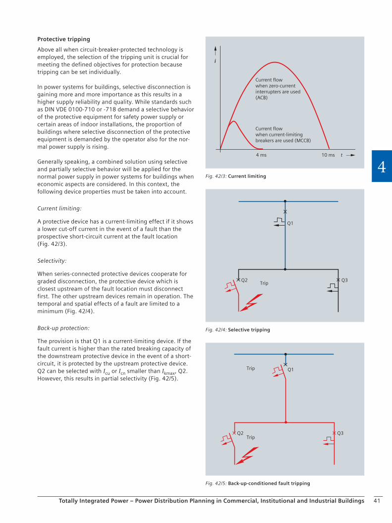
41Totally Integrated Power – Power Distribution Planning in Commercial, Institutional and Industrial Buildings
4
Protective tripping
Above all when circuit-breaker-protected technology is employed, the selection of the tripping unit is crucial for meeting the defined objectives for protection because tripping can be set individually.
In power systems for buildings, selective disconnection is gaining more and more importance as this results in a higher supply reliability and quality. While standards such as DIN VDE 0100-710 or -718 demand a selective behavior of the protective equipment for safety power supply or certain areas of indoor installations, the proportion of buildings where selective disconnection of the protective equipment is demanded by the operator also for the nor-mal power supply is rising.
Generally speaking, a combined solution using selective and partially selective behavior will be applied for the normal power supply in power systems for buildings when economic aspects are considered. In this context, the following device properties must be taken into account.
Current limiting:
A protective device has a current-limiting effect if it shows a lower cut-off current in the event of a fault than the prospective short-circuit current at the fault location (Fig. 42/3).
Selectivity:
When series-connected protective devices cooperate for graded disconnection, the protective device which is closest upstream of the fault location must disconnect first. The other upstream devices remain in operation. The temporal and spatial effects of a fault are limited to a minimum (Fig. 42/4).
Back-up protection:
The provision is that Q1 is a current-limiting device. If the fault current is higher than the rated breaking capacity of the downstream protective device in the event of a short-circuit, it is protected by the upstream protective device. Q2 can be selected with Icu or Icn smaller than Ikmax, Q2. However, this results in partial selectivity (Fig. 42/5).
Current flowwhen current-limiting breakers are used (MCCB)
Current flowwhen zero-current interrupters are used(ACB)
10 ms4 ms
i
t
i
Fig. 42/3: Current limiting
TripQ2
Q1
Q3
Fig. 42/4: Selective tripping
Trip
TripQ2 Q3
Q1
Fig. 42/5: Back-up-conditioned fault tripping
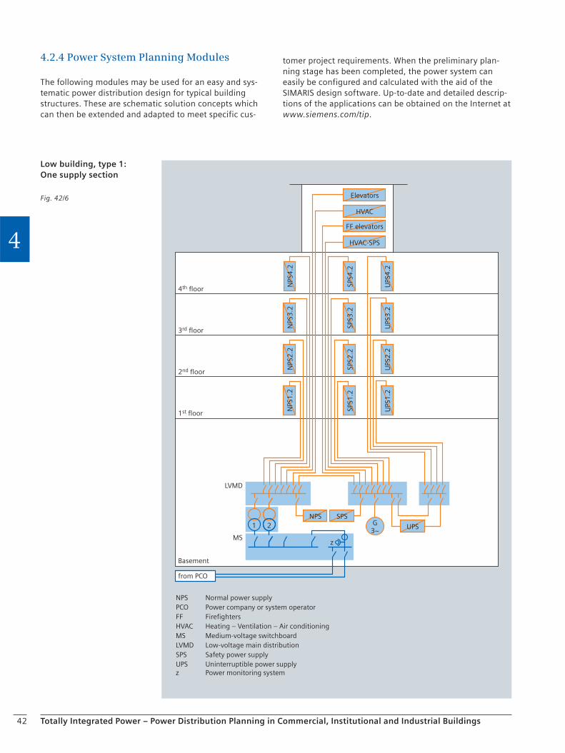
42 Totally Integrated Power – Power Distribution Planning in Commercial, Institutional and Industrial Buildings
4
4.2.4 Power System Planning Modules
The following modules may be used for an easy and sys-tematic power distribution design for typical building structures. These are schematic solution concepts which can then be extended and adapted to meet specific cus-
NPS
3.2
NPS
2.2
NPS
1.2
NPS
4.2
SPS3
.2SP
S4.2
UPS
UPS
3.2
UPS
2.2
UPS
1.2
UPS
4.2
Elevators
HVAC
FF elevators
HVAC-SPS
SPS2
.2SP
S1.2
NPS SPS
4th floor
3rd floor
Basement
from PCO
2nd floor
LVMD
MS
NPS Normal power supplyPCO Power company or system operatorFF FirefightersHVAC Heating – Ventilation – Air conditioningMS Medium-voltage switchboardLVMD Low-voltage main distributionSPS Safety power supplyUPS Uninterruptible power supplyz Power monitoring system
1st floor
21 G3~
z
Low building, type 1:One supply section
Fig. 42/6
tomer project requirements. When the preliminary plan-ning stage has been completed, the power system can easily be configured and calculated with the aid of the SIMARIS design software. Up-to-date and detailed descrip-tions of the applications can be obtained on the Internet at www.siemens.com/tip.
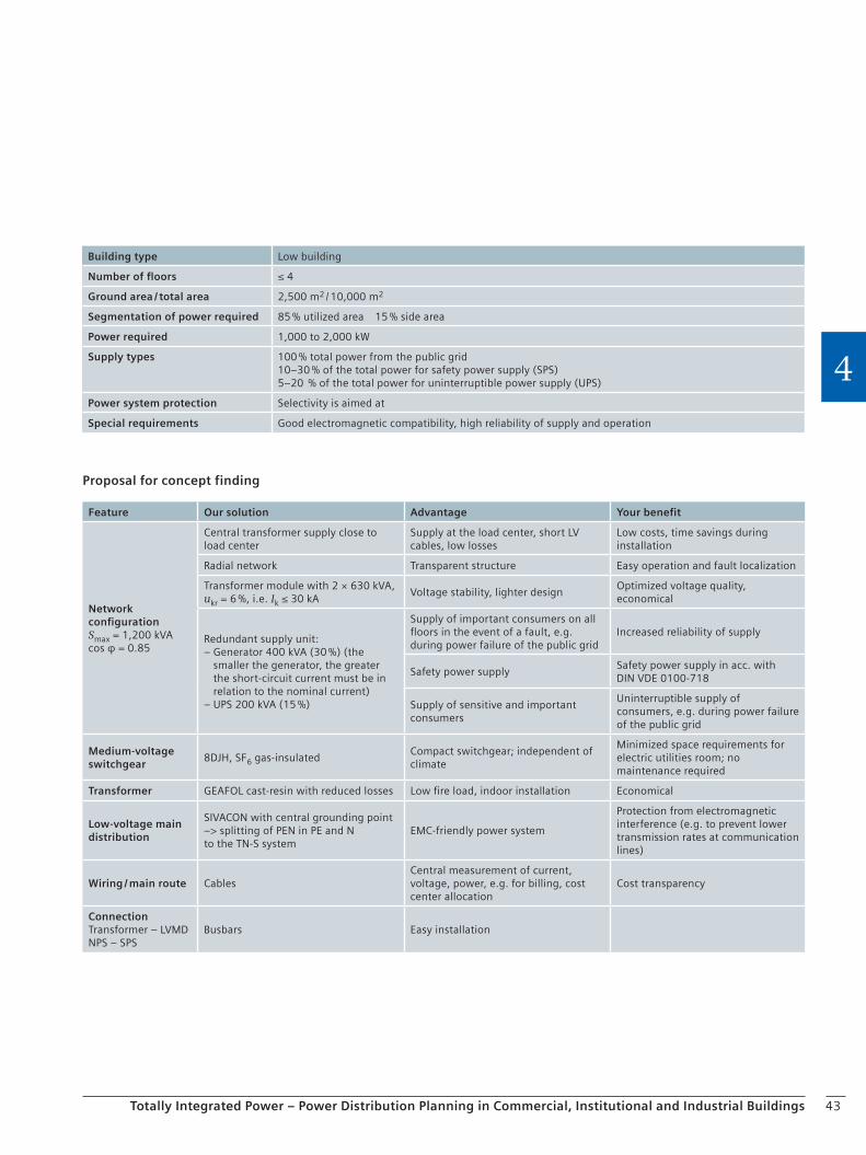
43Totally Integrated Power – Power Distribution Planning in Commercial, Institutional and Industrial Buildings
4
Proposal for concept finding
Building type Low building
Number of floors ≤ 4
Ground area / total area 2,500 m2 / 10,000 m2
Segmentation of power required 85 % utilized area 15 % side area
Power required 1,000 to 2,000 kW
Supply types 100 % total power from the public grid10–30 % of the total power for safety power supply (SPS)5–20 % of the total power for uninterruptible power supply (UPS)
Power system protection Selectivity is aimed at
Special requirements Good electromagnetic compatibility, high reliability of supply and operation
Feature Our solution Advantage Your benefit
Network configurationSmax = 1,200 kVAcos φ = 0.85
Central transformer supply close to load center
Supply at the load center, short LV cables, low losses
Low costs, time savings during installation
Radial network Transparent structure Easy operation and fault localization
Transformer module with 2 × 630 kVA,ukr = 6 %, i.e. Ik ≤ 30 kA
Voltage stability, lighter designOptimized voltage quality, economical
Redundant supply unit:– Generator 400 kVA (30 %) (the
smaller the generator, the greater the short-circuit current must be in relation to the nominal current)
– UPS 200 kVA (15 %)
Supply of important consumers on all floors in the event of a fault, e.g. during power failure of the public grid
Increased reliability of supply
Safety power supplySafety power supply in acc. with DIN VDE 0100-718
Supply of sensitive and important consumers
Uninterruptible supply of consumers, e.g. during power failure of the public grid
Medium-voltage switchgear
8DJH, SF6 gas-insulatedCompact switchgear; independent of climate
Minimized space requirements for electric utilities room; no maintenance required
Transformer GEAFOL cast-resin with reduced losses Low fire load, indoor installation Economical
Low-voltage main distribution
SIVACON with central grounding point –> splitting of PEN in PE and Nto the TN-S system
EMC-friendly power system
Protection from electromagnetic interference (e.g. to prevent lower transmission rates at communication lines)
Wiring / main route CablesCentral measurement of current, voltage, power, e.g. for billing, cost center allocation
Cost transparency
ConnectionTransformer – LVMDNPS – SPS
Busbars Easy installation
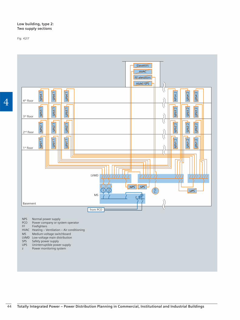
44 Totally Integrated Power – Power Distribution Planning in Commercial, Institutional and Industrial Buildings
4
SPS3
.1SP
S2.1
SPS1
.1SP
S4.1
UPS
UPS
3.2
UPS
2.2
UPS
1.2
UPS
4.2
NPS SPSSP
S3.2
SPS4
.2SP
S2.2
SPS1
.2
NPS
2.2
NPS
3.2
NPS
1.2
NPS
3.1
NPS
2.1
NPS
1.1
NPS
4.1
UPS
3.1
UPS
2.1
UPS
1.1
UPS
4.1
Basement
from PCO
LVMD
MS
NPS Normal power supplyPCO Power company or system operatorFF FirefightersHVAC Heating – Ventilation – Air conditioningMS Medium-voltage switchboardLVMD Low-voltage main distributionSPS Safety power supplyUPS Uninterruptible power supplyz Power monitoring system
NPS
4.2
Elevators
HVAC
FF elevators
HVAC-SPS
4th floor
3rd floor
2nd floor
1st floor
G3~
z
21
Low building, type 2:Two supply sections
Fig. 42/7
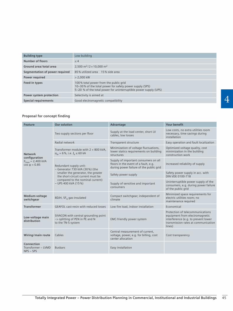
45Totally Integrated Power – Power Distribution Planning in Commercial, Institutional and Industrial Buildings
4
Proposal for concept finding
Building type Low building
Number of floors ≤ 4
Ground area / total area 2,500 m2 / 2 × 10,000 m2
Segmentation of power required 85 % utilized area 15 % side area
Power required > 2,000 kW
Feed-in types 100 % total power from the public grid10–30 % of the total power for safety power supply (SPS)5–20 % of the total power for uninterruptible power supply (UPS)
Power system protection Selectivity is aimed at
Special requirements Good electromagnetic compatibility
Feature Our solution Advantage Your benefit
Network configurationSmax = 2,400 kVAcos φ = 0.85
Two supply sections per floorSupply at the load center, short LV cables, low losses
Low costs, no extra utilities room necessary, time savings during installation
Radial network Transparent structure Easy operation and fault localization
Transformer module with 2 × 800 kVA,ukr = 6 %, i.e. Ik ≤ 60 kA
Minimization of voltage fluctuations, lower statics requirements on building structures
Optimized voltage quality, cost minimization in the building construction work
Redundant supply unit:– Generator 730 kVA (30 %) (the
smaller the generator, the greater the short-circuit current must be compared to the nominal current)
– UPS 400 kVA (15 %)
Supply of important consumers on all floors in the event of a fault, e.g. during power failure of the public grid
Increased reliability of supply
Safety power supplySafety power supply in acc. with DIN VDE 0100-718
Supply of sensitive and important consumers
Uninterruptible power supply of the consumers, e.g. during power failure of the public grid
Medium-voltage switchgear
8DJH, SF6 gas-insulatedCompact switchgear; independent of climate
Minimized space requirements for electric utilities room; no maintenance required
Transformer GEAFOL cast-resin with reduced losses Low fire load, indoor installation Economical
Low-voltage main distribution
SIVACON with central grounding point –> splitting of PEN in PE and Nto the TN-S system
EMC-friendly power system
Protection of telecommunications equipment from electromagnetic interference (e.g. to prevent lower transmission rates at communication lines)
Wiring / main route CablesCentral measurement of current, voltage, power, e.g. for billing, cost center allocation
Cost transparency
ConnectionTransformer – LVMDNPS – SPS
Busbars Easy installation
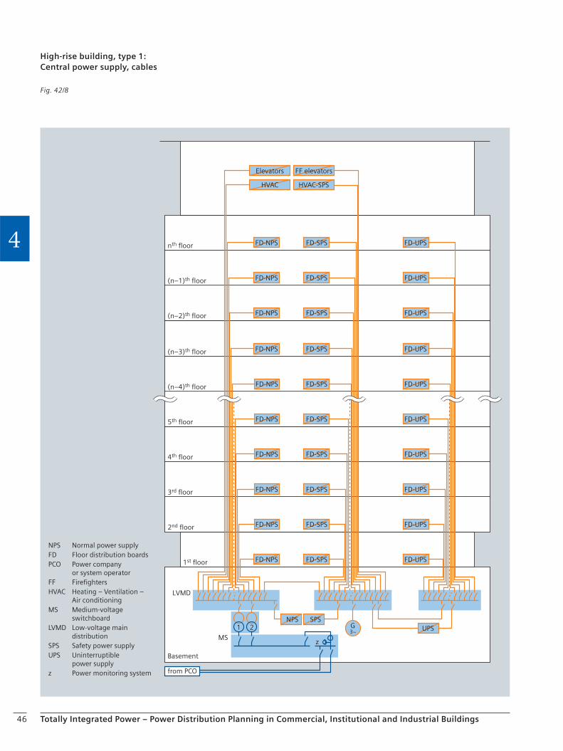
46 Totally Integrated Power – Power Distribution Planning in Commercial, Institutional and Industrial Buildings
4 FD-NPS
FD-NPS
FD-NPS
FD-NPS
FD-NPS
FD-NPS
FD-NPS
Elevators
HVAC
FD-NPS
FD-NPS
FD-NPS
FD-SPS
FD-SPS
FD-SPS
FD-SPS
FD-SPS
FD-SPS
FD-SPS
FF elevators
HVAC-SPS
FD-SPS
FD-SPS
FD-SPS
NPS SPSUPS
FD-UPS
FD-UPS
FD-UPS
FD-UPS
FD-UPS
FD-UPS
FD-UPS
FD-UPS
FD-UPS
FD-UPS
nth floor
(n–1)th floor
(n–2)th floor
(n–3)th floor
(n–4)th floor
5th floor
4th floor
3rd floor
2nd floor
Basement
from PCO
1st floor
LVMD
MS
NPS Normal power supplyFD Floor distribution boardsPCO Power company
or system operatorFF FirefightersHVAC Heating – Ventilation –
Air conditioningMS Medium-voltage
switchboardLVMD Low-voltage main
distributionSPS Safety power supplyUPS Uninterruptible
power supplyz Power monitoring system
21 G3~
z
High-rise building, type 1:Central power supply, cables
Fig. 42/8
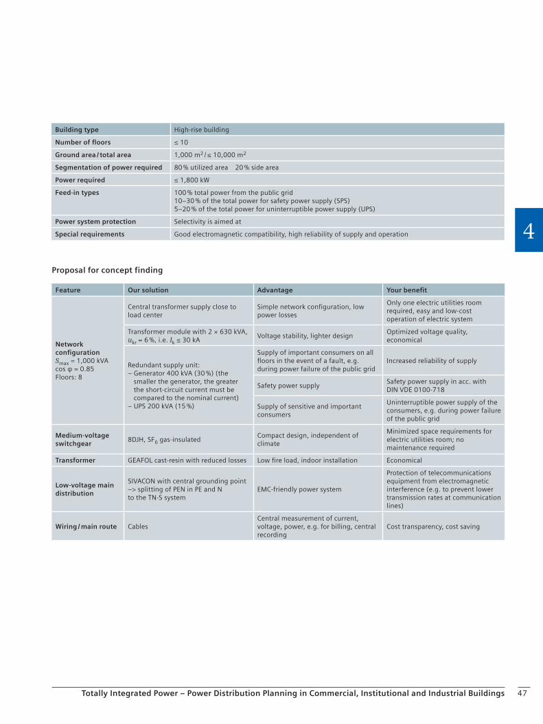
47Totally Integrated Power – Power Distribution Planning in Commercial, Institutional and Industrial Buildings
4
Proposal for concept finding
Building type High-rise building
Number of floors ≤ 10
Ground area / total area 1,000 m2 / ≤ 10,000 m2
Segmentation of power required 80 % utilized area 20 % side area
Power required ≤ 1,800 kW
Feed-in types 100 % total power from the public grid10–30 % of the total power for safety power supply (SPS)5–20 % of the total power for uninterruptible power supply (UPS)
Power system protection Selectivity is aimed at
Special requirements Good electromagnetic compatibility, high reliability of supply and operation
Feature Our solution Advantage Your benefit
Network configurationSmax = 1,000 kVAcos φ = 0.85Floors: 8
Central transformer supply close to load center
Simple network configuration, low power losses
Only one electric utilities room required, easy and low-cost operation of electric system
Transformer module with 2 × 630 kVA,ukr = 6 %, i.e. Ik ≤ 30 kA
Voltage stability, lighter designOptimized voltage quality, economical
Redundant supply unit:– Generator 400 kVA (30 %) (the
smaller the generator, the greater the short-circuit current must be compared to the nominal current)
– UPS 200 kVA (15 %)
Supply of important consumers on all floors in the event of a fault, e.g. during power failure of the public grid
Increased reliability of supply
Safety power supplySafety power supply in acc. with DIN VDE 0100-718
Supply of sensitive and important consumers
Uninterruptible power supply of the consumers, e.g. during power failure of the public grid
Medium-voltage switchgear
8DJH, SF6 gas-insulatedCompact design, independent of climate
Minimized space requirements for electric utilities room; no maintenance required
Transformer GEAFOL cast-resin with reduced losses Low fire load, indoor installation Economical
Low-voltage main distribution
SIVACON with central grounding point –> splitting of PEN in PE and Nto the TN-S system
EMC-friendly power system
Protection of telecommunications equipment from electromagnetic interference (e.g. to prevent lower transmission rates at communication lines)
Wiring / main route CablesCentral measurement of current, voltage, power, e.g. for billing, central recording
Cost transparency, cost saving
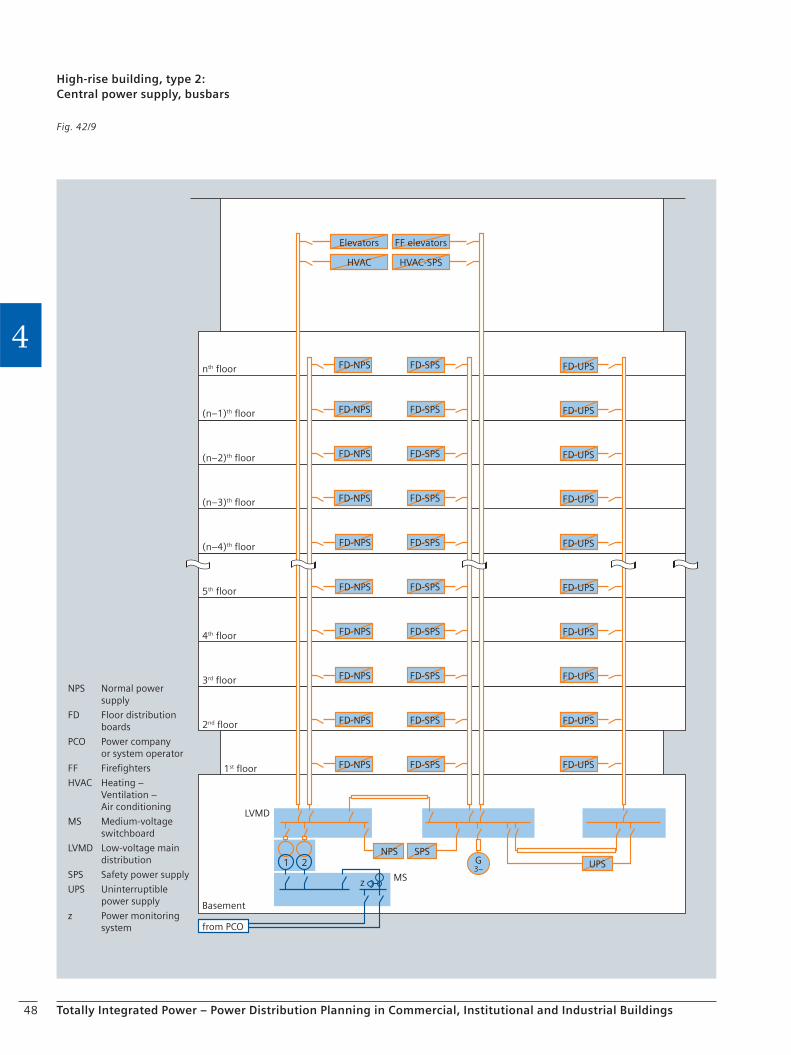
48 Totally Integrated Power – Power Distribution Planning in Commercial, Institutional and Industrial Buildings
4FD-NPS
FD-NPS
FD-NPS
FD-NPS
FD-NPS
FD-NPS
FD-NPS
Elevators
HVAC
FD-NPS
FD-NPS
FD-NPS
FD-SPS
FD-SPS
FD-SPS
FD-SPS
FD-SPS
FD-SPS
FD-SPS
FF elevators
HVAC-SPS
FD-SPS
FD-SPS
FD-SPS
NPS SPSUPS
FD-UPS
FD-UPS
FD-UPS
FD-UPS
FD-UPS
FD-UPS
FD-UPS
FD-UPS
FD-UPS
FD-UPS
nth floor
(n–1)th floor
(n–2)th floor
(n–3)th floor
(n–4)th floor
5th floor
4th floor
3rd floor
2nd floor
Basement
from PCO
1st floor
LVMD
MS
NPS Normal power supply
FD Floor distribution boards
PCO Power company or system operator
FF Firefighters
HVAC Heating – Ventilation – Air conditioning
MS Medium-voltage switchboard
LVMD Low-voltage main distribution
SPS Safety power supply
UPS Uninterruptible power supply
z Power monitoring system
21 G3~
z
High-rise building, type 2:Central power supply, busbars
Fig. 42/9
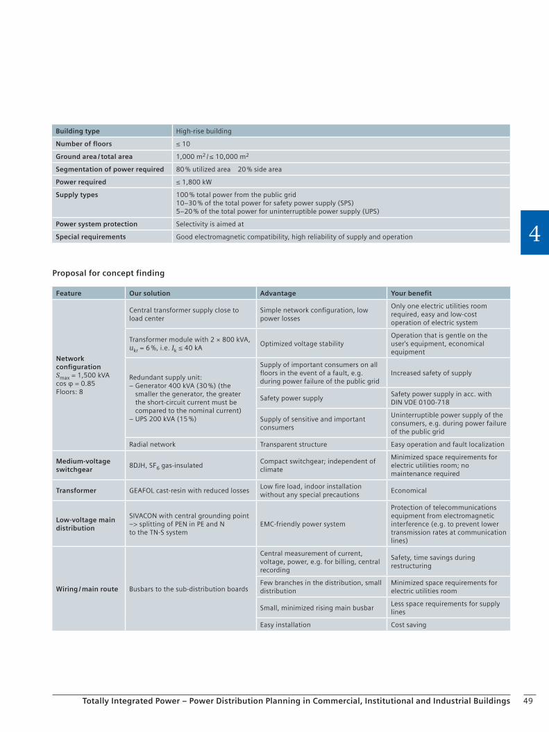
49Totally Integrated Power – Power Distribution Planning in Commercial, Institutional and Industrial Buildings
4
Proposal for concept finding
Building type High-rise building
Number of floors ≤ 10
Ground area / total area 1,000 m2 / ≤ 10,000 m2
Segmentation of power required 80 % utilized area 20 % side area
Power required ≤ 1,800 kW
Supply types 100 % total power from the public grid10–30 % of the total power for safety power supply (SPS)5–20 % of the total power for uninterruptible power supply (UPS)
Power system protection Selectivity is aimed at
Special requirements Good electromagnetic compatibility, high reliability of supply and operation
Feature Our solution Advantage Your benefit
Network configurationSmax = 1,500 kVAcos φ = 0.85Floors: 8
Central transformer supply close to load center
Simple network configuration, low power losses
Only one electric utilities room required, easy and low-cost operation of electric system
Transformer module with 2 × 800 kVA,ukr = 6 %, i.e. Ik ≤ 40 kA
Optimized voltage stabilityOperation that is gentle on the user's equipment, economical equipment
Redundant supply unit:– Generator 400 kVA (30 %) (the
smaller the generator, the greater the short-circuit current must be compared to the nominal current)
– UPS 200 kVA (15 %)
Supply of important consumers on all floors in the event of a fault, e.g. during power failure of the public grid
Increased safety of supply
Safety power supplySafety power supply in acc. with DIN VDE 0100-718
Supply of sensitive and important consumers
Uninterruptible power supply of the consumers, e.g. during power failure of the public grid
Radial network Transparent structure Easy operation and fault localization
Medium-voltage switchgear
8DJH, SF6 gas-insulatedCompact switchgear; independent of climate
Minimized space requirements for electric utilities room; no maintenance required
Transformer GEAFOL cast-resin with reduced lossesLow fire load, indoor installation without any special precautions
Economical
Low-voltage main distribution
SIVACON with central grounding point –> splitting of PEN in PE and Nto the TN-S system
EMC-friendly power system
Protection of telecommunications equipment from electromagnetic interference (e.g. to prevent lower transmission rates at communication lines)
Wiring / main route Busbars to the sub-distribution boards
Central measurement of current, voltage, power, e.g. for billing, central recording
Safety, time savings during restructuring
Few branches in the distribution, small distribution
Minimized space requirements for electric utilities room
Small, minimized rising main busbarLess space requirements for supply lines
Easy installation Cost saving
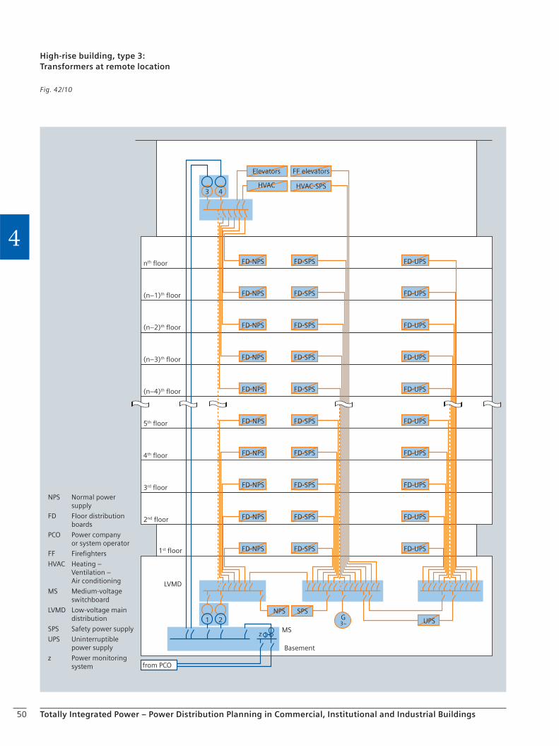
50 Totally Integrated Power – Power Distribution Planning in Commercial, Institutional and Industrial Buildings
4FD-NPS
FD-NPS
FD-NPS
FD-NPS
FD-NPS
FD-NPS
FD-NPS
Elevators
HVAC
FD-NPS
FD-NPS
FD-NPS
FD-SPS
FD-SPS
FD-SPS
FD-SPS
FD-SPS
FD-SPS
FD-SPS
FF elevators
HVAC-SPS
FD-SPS
FD-SPS
FD-SPS
NPS SPSUPS
FD-UPS
FD-UPS
FD-UPS
FD-UPS
FD-UPS
FD-UPS
FD-UPS
FD-UPS
FD-UPS
FD-UPS
nth floor
(n–1)th floor
(n–2)th floor
(n–3)th floor
(n–4)th floor
5th floor
4th floor
3rd floor
2nd floor
Basement
from PCO
1st floor
LVMD
MS
NPS Normal power supply
FD Floor distributionboards
PCO Power companyor system operator
FF Firefighters
HVAC Heating –Ventilation –Air conditioning
MS Medium-voltageswitchboard
LVMD Low-voltage maindistribution
SPS Safety power supply
UPS Uninterruptiblepower supply
z Power monitoringsystem
21 G3~
z
43
High-rise building, type 3:Transformers at remote location
Fig. 42/10
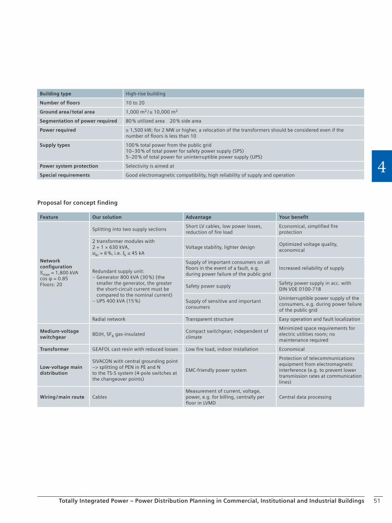
51Totally Integrated Power – Power Distribution Planning in Commercial, Institutional and Industrial Buildings
4
Proposal for concept finding
Building type High-rise building
Number of floors 10 to 20
Ground area / total area 1,000 m2 / ≤ 10,000 m2
Segmentation of power required 80 % utilized area 20 % side area
Power required ≥ 1,500 kW; for 2 MW or higher, a relocation of the transformers should be considered even if the number of floors is less than 10
Supply types 100 % total power from the public grid10–30 % of total power for safety power supply (SPS)5–20 % of total power for uninterruptible power supply (UPS)
Power system protection Selectivity is aimed at
Special requirements Good electromagnetic compatibility, high reliability of supply and operation
Feature Our solution Advantage Your benefit
Network configurationSmax = 1,800 kVAcos φ = 0.85Floors: 20
Splitting into two supply sectionsShort LV cables, low power losses, reduction of fire load
Economical, simplified fire protection
2 transformer modules with 2 + 1 × 630 kVA,ukr = 6 %, i.e. Ik ≤ 45 kA
Voltage stability, lighter designOptimized voltage quality, economical
Redundant supply unit:– Generator 800 kVA (30 %) (the
smaller the generator, the greater the short-circuit current must be compared to the nominal current)
– UPS 400 kVA (15 %)
Supply of important consumers on all floors in the event of a fault, e.g. during power failure of the public grid
Increased reliability of supply
Safety power supplySafety power supply in acc. with DIN VDE 0100-718
Supply of sensitive and important consumers
Uninterruptible power supply of the consumers, e.g. during power failure of the public grid
Radial network Transparent structure Easy operation and fault localization
Medium-voltage switchgear
8DJH, SF6 gas-insulatedCompact switchgear; independent of climate
Minimized space requirements for electric utilities room; no maintenance required
Transformer GEAFOL cast-resin with reduced losses Low fire load, indoor installation Economical
Low-voltage main distribution
SIVACON with central grounding point –> splitting of PEN in PE and Nto the TS-S system (4-pole switches at the changeover points)
EMC-friendly power system
Protection of telecommunications equipment from electromagnetic interference (e.g. to prevent lower transmission rates at communication lines)
Wiring / main route CablesMeasurement of current, voltage, power, e.g. for billing, centrally per floor in LVMD
Central data processing

52 Totally Integrated Power – Power Distribution Planning in Commercial, Institutional and Industrial Buildings
4FD-NPS
FD-NPS
FD-NPS
FD-NPS
FD-NPS
FD-NPS
FD-NPS
Elevators
HVAC
FD-NPS
FD-NPS
FD-NPS
FD-SPS
FD-SPS
FD-SPS
FD-SPS
FD-SPS
FD-SPS
FD-SPS
FF elevators
HVAC-SPS
FD-SPS
FD-SPS
FD-SPS
NPS SPSUPS
FD-UPS
FD-UPS
FD-UPS
FD-UPS
FD-UPS
FD-UPS
FD-UPS
FD-UPS
FD-UPS
FD-UPS
nth floor
(n–1)th floor
(n–2)th floor
(n–3)th floor
(n–4)th floor
5th floor
4th floor
3rd floor
2nd floor
Basement
from PCO
1st floor
LVMD
MS
UPS
NPS Normal power supply
FD Floor distribution boards
PCO Power company or system operator
FF Firefighters
HVAC Heating – Ventilation – Air conditioning
MS Medium-voltage switchboard
LVMD Low-voltage main distribution
SPS Safety power supply
UPS Uninterruptible power supply
z Power monitoring system
21 3
54 6
G3~
z
G3~
High-rise building, type 4:Distributed supply, cables
Fig. 42/11

53Totally Integrated Power – Power Distribution Planning in Commercial, Institutional and Industrial Buildings
4
Proposal for concept finding
Building type High-rise building
Number of floors > 20
Ground area / total area 1,000 m2 / > 20,000 m2
Segmentation of power required 80 % utilized area 20 % side area
Power required ≤ 2,000 kW
Feed-in types 100 % total power from the public grid10–30 % of total power for safety power supply (SPS)5–20 % of total power for uninterruptible power supply (UPS)
Power system protection Selectivity is aimed at
Special requirements Good electromagnetic compatibility, high reliability of supply and operation
Feature Our solution Advantage Your benefit
Network configurationSmax = 3,600 kVAcos φ = 0.85Floors: 25
Splitting into two supply sectionsShort LV cables, low power losses, reduction of fire load
Economical, simplified fire protection
2 transformer modules with 3 × 630 kVA,ukr = 6 %, i.e. Ik ≤ 45 kA
Voltage stability, lighter designOptimized voltage quality, eco-nomical
Redundant supply unit:– Generator 2 × 500 kVA (30 %) (the
smaller the generator, the greater the short-circuit current must be compared to the nominal current)
– UPS 2 × 250 kVA (15 %)
Supply of important consumers on all floors in the event of a fault, e.g. during power failure of the public grid
Increased reliability of supply
Safety power supplySafety power supply in acc. with DIN VDE 0100-718
Supply of sensitive and important consumers
Uninterruptible power supply of the consumers, e.g. during power failure of the public grid
Radial network Transparent structure Easy operation and fault localization
Medium-voltage switchgear
8DJH, SF6 gas-insulatedCompact switchgear; independent of climate
Minimized space requirements; no maintenance required
Transformer GEAFOL cast-resin with reduced lossesLow fire load, indoor installation without any special precautions
Economical
Low-voltage main distribution
SIVACON with central grounding point –> splitting of PEN in PE and Nto the TN-S system (4-pole switches for connecting the LVMDs)
EMC-friendly power system
Protection of telecommunications equipment from electromagnetic interference (e.g. to prevent lower transmission rates at communication lines)
Wiring / main route CablesCentral measurement of current, voltage, power, e.g. for billing, cost center allocation
Cost transparency, cost saving
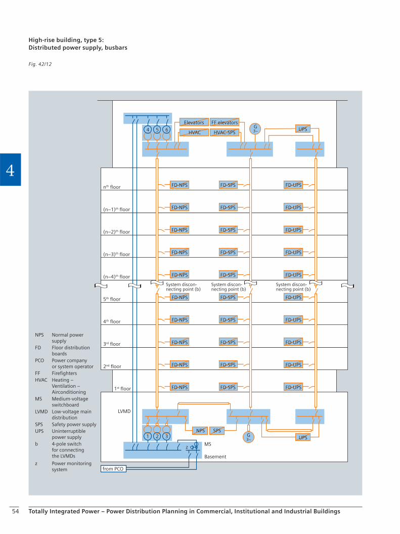
54 Totally Integrated Power – Power Distribution Planning in Commercial, Institutional and Industrial Buildings
4FD-NPS
FD-NPS
FD-NPS
FD-NPS
FD-NPS
FD-NPS
FD-NPS
Elevators
HVAC
FD-NPS
FD-NPS
FD-NPS
FD-SPS
FD-SPS
FD-SPS
FD-SPS
FD-SPS
FD-SPS
FD-SPS
FF elevators
HVAC-SPS
FD-SPS
FD-SPS
FD-SPS
NPS SPSUPS
FD-UPS
FD-UPS
FD-UPS
FD-UPS
FD-UPS
FD-UPS
FD-UPS
FD-UPS
FD-UPS
FD-UPS
nth floor
(n–1)th floor
(n–2)th floor
(n–3)th floor
(n–4)th floor
5th floor
4th floor
3rd floor
2nd floor
Basement
from PCO
1st floor
LVMD
MS
NPS Normal power supplyFD Floor distribution boardsPCO Power company or system operatorFF FirefightersHVAC Heating – Ventilation – AirconditioningMS Medium-voltage switchboardLVMD Low-voltage main distributionSPS Safety power supplyUPS Uninterruptible power supplyb 4-pole switch for connecting the LVMDs
z Power monitoring system
UPS
System discon-necting point (b)
System discon-necting point (b)
System discon-necting point (b)
21 3
54 6
G3~
z
G3~
High-rise building, type 5:Distributed power supply, busbars
Fig. 42/12
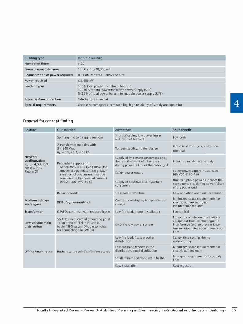
55Totally Integrated Power – Power Distribution Planning in Commercial, Institutional and Industrial Buildings
4
Proposal for concept finding
Building type High-rise building
Number of floors > 20
Ground area / total area 1,000 m2 / > 20,000 m2
Segmentation of power required 80 % utilized area 20 % side area
Power required ≤ 2,000 kW
Feed-in types 100 % total power from the public grid10–30 % of total power for safety power supply (SPS)5–20 % of total power for uninterruptible power supply (UPS)
Power system protection Selectivity is aimed at
Special requirements Good electromagnetic compatibility, high reliability of supply and operation
Feature Our solution Advantage Your benefit
Network configurationSmax = 4,000 kVAcos φ = 0.85Floors: 21
Splitting into two supply sectionsShort LV cables, low power losses, reduction of fire load
Low costs
2 transformer modules with 3 × 800 kVA,ukr = 6 %, i.e. Ik ≤ 60 kA
Voltage stability, lighter designOptimized voltage quality, eco-nomical
Redundant supply unit:– Generator 2 × 630 kVA (30 %) (the
smaller the generator, the greater the short-circuit current must be compared to the nominal current)
– UPS 2 × 300 kVA (15 %)
Supply of important consumers on all floors in the event of a fault, e.g. during power failure of the public grid
Increased reliability of supply
Safety power supplySafety power supply in acc. with DIN VDE 0100-718
Supply of sensitive and important consumers
Uninterruptible power supply of the consumers, e.g. during power failure of the public grid
Radial network Transparent structure Easy operation and fault localization
Medium-voltage switchgear
8DJH, SF6 gas-insulatedCompact switchgear; independent of climate
Minimized space requirements for electric utilities room; no maintenance required
Transformer GEAFOL cast-resin with reduced losses Low fire load, indoor installation Economical
Low-voltage main distribution
SIVACON with central grounding point –> splitting of PEN in PE and Nto the TN-S system (4-pole switches for connecting the LVMDs)
EMC-friendly power system
Protection of telecommunications equipment from electromagnetic interference (e.g. to prevent lower transmission rates at communication lines)
Wiring / main route Busbars to the sub-distribution boards
Low fire load, flexible power distribution
Safety, time savings during restructuring
Few outgoing feeders in the distribution, small distribution
Minimized space requirements for electric utilities room
Small, minimized rising main busbarLess space requirements for supply lines
Easy installation Cost reduction
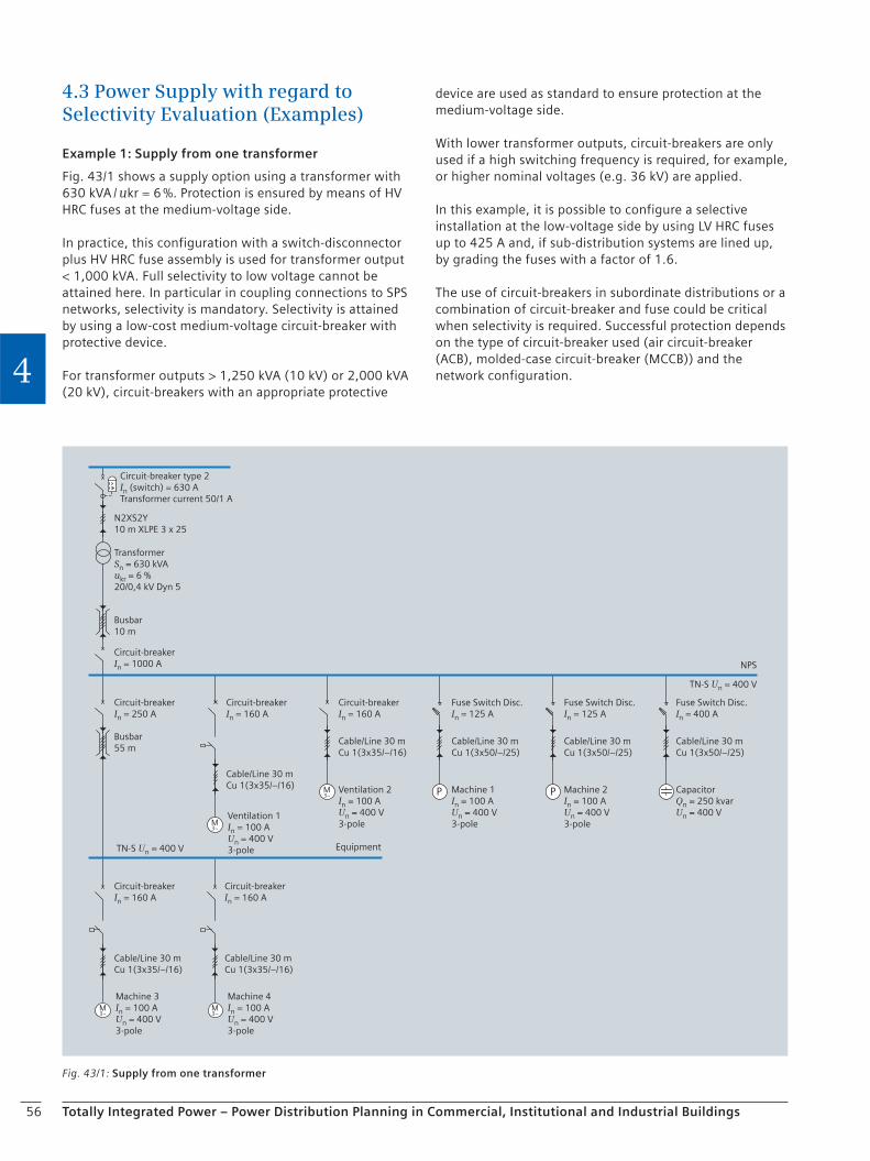
56 Totally Integrated Power – Power Distribution Planning in Commercial, Institutional and Industrial Buildings
4
4.3 Power Supply with regard to Selectivity Evaluation (Examples)
Example 1: Supply from one transformer
Fig. 43/1 shows a supply option using a transformer with 630 kVA / ukr = 6 %. Protection is ensured by means of HV HRC fuses at the medium-voltage side.
In practice, this configuration with a switch-disconnector plus HV HRC fuse assembly is used for transformer output < 1,000 kVA. Full selectivity to low voltage cannot be attained here. In particular in coupling connections to SPS networks, selectivity is mandatory. Selectivity is attained by using a low-cost medium-voltage circuit-breaker with protective device.
For transformer outputs > 1,250 kVA (10 kV) or 2,000 kVA (20 kV), circuit-breakers with an appropriate protective
device are used as standard to ensure protection at the medium-voltage side.
With lower transformer outputs, circuit-breakers are only used if a high switching frequency is required, for example, or higher nominal voltages (e.g. 36 kV) are applied.
In this example, it is possible to configure a selective installation at the low-voltage side by using LV HRC fuses up to 425 A and, if sub-distribution systems are lined up, by grading the fuses with a factor of 1.6.
The use of circuit-breakers in subordinate distributions or a combination of circuit-breaker and fuse could be critical when selectivity is required. Successful protection depends on the type of circuit-breaker used (air circuit-breaker (ACB), molded-case circuit-breaker (MCCB)) and the network configuration.
Fig. 43/1: Supply from one transformer
M3~
M3~
M3~
M3~
P P
Circuit-breaker type 2In (switch) = 630 ATransformer current 50/1 A
TransformerSn = 630 kVAukr = 6 %20/0,4 kV Dyn 5
N2XS2Y10 m XLPE 3 x 25
Circuit-breakerIn = 160 A
Busbar10 m
Circuit-breakerIn = 1000 A
Circuit-breakerIn = 250 A
Circuit-breakerIn = 160 A
NPS
TN-S Un = 400 V
Circuit-breakerIn = 160 A
Fuse Switch Disc.In = 125 A
Circuit-breakerIn = 160 A
Cable/Line 30 mCu 1(3x35/–/16)
Cable/Line 30 mCu 1(3x35/–/16)
Machine 3In = 100 AUn = 400 V3-pole
Machine 4In = 100 AUn = 400 V3-pole
Fuse Switch Disc.In = 125 A
Fuse Switch Disc.In = 400 A
Cable/Line 30 mCu 1(3x35/–/16)
Cable/Line 30 mCu 1(3x50/–/25)
Cable/Line 30 mCu 1(3x50/–/25)
Cable/Line 30 mCu 1(3x50/–/25)
Cable/Line 30 mCu 1(3x35/–/16)
Busbar55 m
TN-S Un = 400 V Equipment
Ventilation 2In = 100 AUn = 400 V3-pole
Machine 1In = 100 AUn = 400 V3-pole
Machine 2In = 100 AUn = 400 V3-pole
CapacitorQn = 250 kvarUn = 400 VVentilation 1
In = 100 AUn = 400 V3-pole
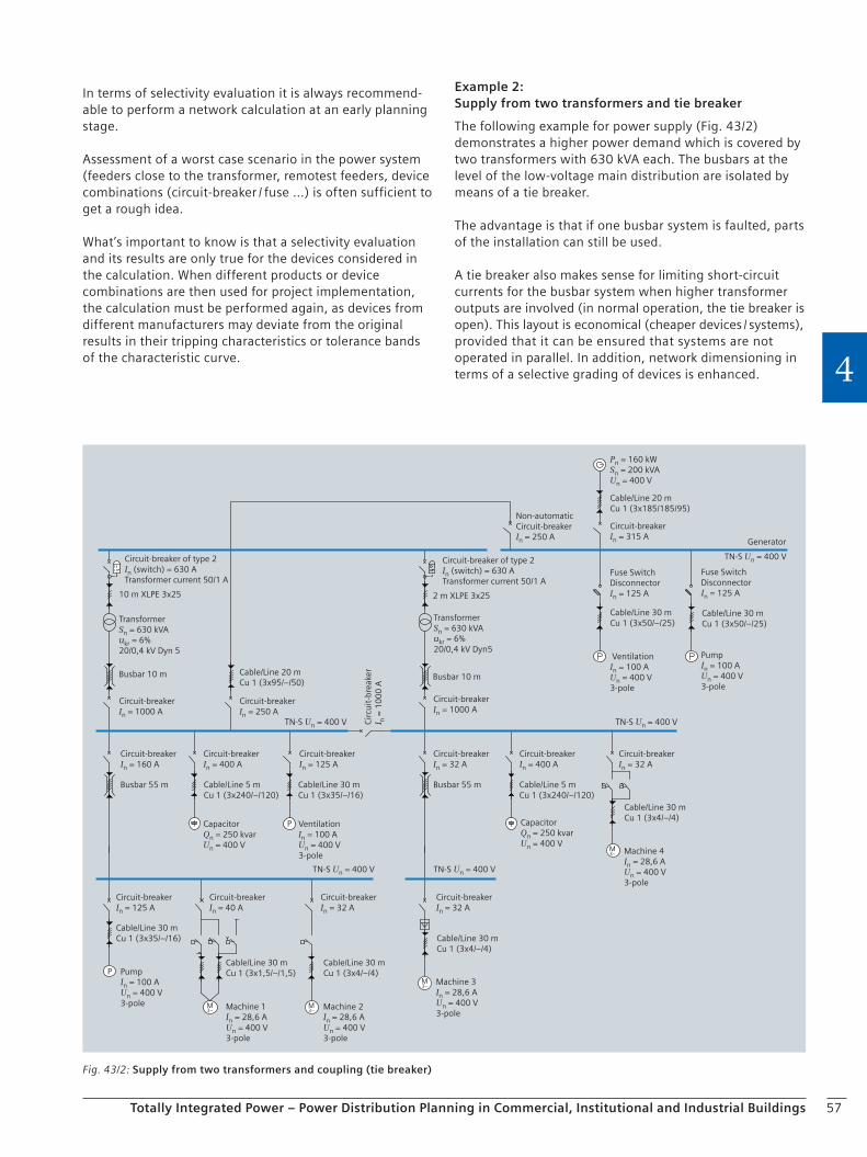
57Totally Integrated Power – Power Distribution Planning in Commercial, Institutional and Industrial Buildings
4
In terms of selectivity evaluation it is always recommend-able to perform a network calculation at an early planning stage.
Assessment of a worst case scenario in the power system (feeders close to the transformer, remotest feeders, device combinations (circuit-breaker / fuse …) is often sufficient to get a rough idea.
What’s important to know is that a selectivity evaluation and its results are only true for the devices considered in the calculation. When different products or device combinations are then used for project implementation, the calculation must be performed again, as devices from different manufacturers may deviate from the original results in their tripping characteristics or tolerance bands of the characteristic curve.
Example 2: Supply from two transformers and tie breaker
The following example for power supply (Fig. 43/2) demonstrates a higher power demand which is covered by two transformers with 630 kVA each. The busbars at the level of the low-voltage main distribution are isolated by means of a tie breaker.
The advantage is that if one busbar system is faulted, parts of the installation can still be used.
A tie breaker also makes sense for limiting short-circuit currents for the busbar system when higher transformer outputs are involved (in normal operation, the tie breaker is open). This layout is economical (cheaper devices / systems), provided that it can be ensured that systems are not operated in parallel. In addition, network dimensioning in terms of a selective grading of devices is enhanced.
Fig. 43/2: Supply from two transformers and coupling (tie breaker)
M3~
M3~
M3~
P
M3~
P
TransformerSn = 630 kVAukr = 6%20/0,4 kV Dyn 5
Circuit-breaker of type 2In (switch) = 630 ATransformer current 50/1 A
10 m XLPE 3x25
Busbar 10 m
Circuit-breakerIn = 1000 A
Pn = 160 kWSn = 200 kVAUn = 400 V
TN-S Un = 400 V TN-S Un = 400 V
Cable/Line 20 mCu 1 (3x185/185/95)
Circuit-breakerIn = 315 A
Non-automaticCircuit-breakerIn = 250 A
Busbar 10 m
Busbar 55 m
Generator
TN-S Un = 400 V
Cable/Line 30 mCu 1 (3x50/–/25)
Cable/Line 30 mCu 1 (3x50/–/25)
PumpIn = 100 AUn = 400 V3-pole
Fuse SwitchDisconnectorIn = 125 A
Fuse SwitchDisconnectorIn = 125 A
VentilationIn = 100 AUn = 400 V3-pole
2 m XLPE 3x25
TransformerSn = 630 kVAukr = 6%20/0,4 kV Dyn5
Circuit-breakerIn = 1000 A
Circuit-breakerIn = 400 A
Circuit-breakerIn = 160 A
Circuit-breakerIn = 125 A
Circuit-breakerIn = 250 A
Busbar 55 m
Circuit-breakerIn = 32 A
TN-S Un = 400 VTN-S Un = 400 V Cir
cuit
-bre
aker
I n =
10
00
A
Cable/Line 20 mCu 1 (3x95/–/50)
Circuit-breaker of type 2In (switch) = 630 ATransformer current 50/1 A
Circuit-breakerIn = 32 A
Circuit-breakerIn = 400 A
Circuit-breakerIn = 32 A
Circuit-breakerIn = 40 A
Circuit-breakerIn = 125 A
Circuit-breakerIn = 32 A
Cable/Line 5 mCu 1 (3x240/–/120)
Cable/Line 30 mCu 1 (3x4/–/4)
Cable/Line 5 mCu 1 (3x240/–/120)
Cable/Line 30 mCu 1 (3x35/–/16)
Cable/Line 30 mCu 1 (3x4/–/4)
Cable/Line 30 mCu 1 (3x1,5/–/1,5)
Cable/Line 30 mCu 1 (3x4/–/4)
Cable/Line 30 mCu 1 (3x35/–/16)
VentilationIn = 100 AUn = 400 V3-pole
PumpIn = 100 AUn = 400 V3-pole
CapacitorQn = 250 kvarUn = 400 V
CapacitorQn = 250 kvarUn = 400 V
Machine 1In = 28,6 AUn = 400 V3-pole
Machine 2In = 28,6 AUn = 400 V3-pole
Machine 3In = 28,6 AUn = 400 V3-pole
Machine 4In = 28,6 AUn = 400 V3-pole

58 Totally Integrated Power – Power Distribution Planning in Commercial, Institutional and Industrial Buildings
4
Example 3: Redundant power supply / safety power supply with generator
If a redundant power supply system is desired or stipu-lated, the networks are coupled by cables or busbars (Fig. 43/3). For safety reasons, installation components must be erected separately, surrounded by suitable fire barriers. The regional expert (TÜV, expert, Association of Property Insurers, etc.) should be involved in the imple-mentation planning at an early stage.
The connection to the public power supply system (NPS = normal power supply) is made by a circuit-breaker feeder in the redundant power supply system (SPS = safety power supply), which provides protective functions and enables separate operation of installation components.
A corresponding feeder circuit-breaker on the NPS side allows for disconnecting and protecting the cable / busbar line. Two circuit-breakers are required as a coupling be-tween the NPS and SPS networks.
The design of the transformer circuit-breakers, tie breakers and generator circuit-breakers (3-pole or 4-pole) depends on the power system design (distance of NPS / SPS), the grounding concept and the power system philosophy of the inspecting body (TÜV, expert, etc.). Siemens recom-mends the use of 4-pole devices when distances between NPS and SPS are greater than 50 m. This way, the power systems are decoupled (also refer to section 9.1, Electro-magnetic Compatibility (EMC)).
The configuration of the SPS should be kept as simple as possible in view of the selectivity requirement. Complex power supply systems, combinations of circuit-breaker and fuses as well as line-ups of sub-distribution systems should be avoided, if possible.
Note:
A network calculation at the planning start is highly recommended. The following should be verified:
1. During normal operation, the normal power supply system feeds the safety supply equipment (transformer circuit-breaker ON, tie breaker ON, generator circuit-breaker OFF).
Is the transformer output sufficient to cover the power demand of the NPS and SPS?
2. When the switchgear is operated as described in para-graph 1, the maximum short-circuit current applied on the SPS busbar is shaped by the transformers.
Is the breaking capacity of the devices connected in the SPS sufficient?
3. In case of a fault on the NPS busbar, the generator takes over power supply of the connected equipment (trans-former circuit-breaker ON or OFF (depending on the fault), tie breaker OFF, generator circuit-breaker ON). In this operating condition, the minimum short-circuit current of the generator is critical.
Is the minimum short-circuit current sufficient to meet the tripping times required in case of a fault (5 seconds for stationary loads (machines), 0.4 seconds for non-stationary loads (equipment connected to power outlets), alternatives for protection according to DIN VDE 100 Part 410 (local equipotential bonding, touch voltage < 50 V) have not been taken into account in this case)?
4. The power system may also have to be rated and verified to meet the maximum required voltage drop specification.
Generator
Cable / Line
Cable / Line
Smoke extractionNumber of poles 3+n
Elevator for fire fightersNumber of poles 3+n
Fuse switchdisconnector
LMVD SPS
From NetworkLVMD GPS
Circuit-breaker 1.1 Circuit-breaker 1.2
Cable / Line
Fuse switchdisconnector
20 m
30 m 30 m
Un = 400 V Un = 400 V
TN – S = 400VIn = 1000 A In = 1000 A
G
Fig. 43/3: Redundant power supply / safety power supply with generator
Chapter 5Dimensioning of the Main Components for Power Supply
5.1 Medium-voltage Switchgear 60
5.2 Pressure Development in Switchgear Rooms 69
5.3 Distribution Transformers (GEAFOL) 70
5.4 Oil-immersed Distribution Transformers 75
5.5 Low-voltage Switchgear 79
5.6 Busbar Trunking Systems 96
5.7 Distribution Boards for Sub-distribution Systems 102
5.8 Uninterruptible Power Supply System (UPS) 104
5.9 Standby Power Supply 108
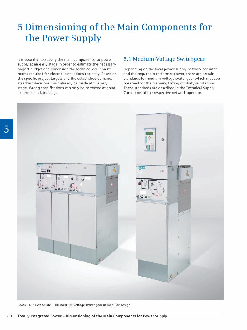
60 Totally Integrated Power – Dimensioning of the Main Components for Power Supply
5
It is essential to specify the main components for power supply at an early stage in order to estimate the necessary project budget and dimension the technical equipment rooms required for electric installations correctly. Based on the specific project targets and the established demand, steadfast decisions must already be made at this very stage. Wrong specifications can only be corrected at great expense at a later stage.
5.1 Medium-Voltage Switchgear
Depending on the local power supply network operator and the required transformer power, there are certain standards for medium-voltage switchgear which must be observed for the planning / sizing of utility substations. These standards are described in the Technical Supply Conditions of the respective network operator.
5 Dimensioning of the Main Components for the Power Supply
Photo 51/1: Extendible 8DJH medium-voltage switchgear in modular design
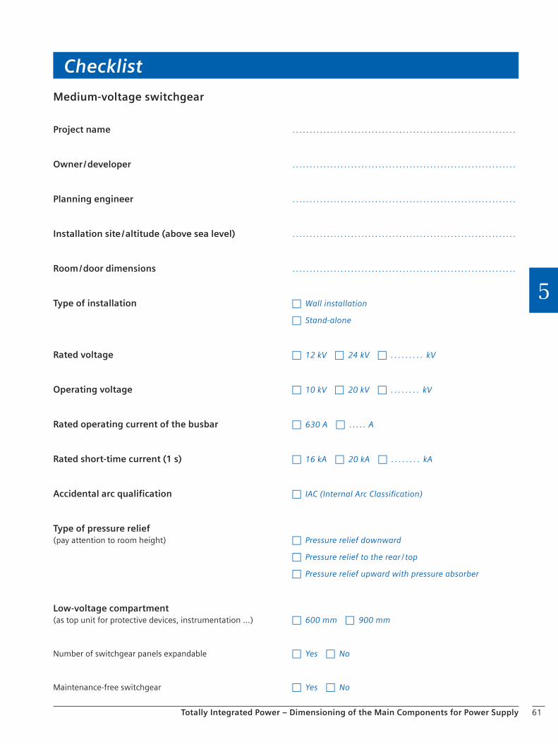
61
Checklist
Totally Integrated Power – Dimensioning of the Main Components for Power Supply
5
Medium-voltage switchgear
Project name . . . . . . . . . . . . . . . . . . . . . . . . . . . . . . . . . . . . . . . . . . . . . . . . . . . . . . . . . . . . . . . . .
Owner / developer . . . . . . . . . . . . . . . . . . . . . . . . . . . . . . . . . . . . . . . . . . . . . . . . . . . . . . . . . . . . . . . . .
Planning engineer . . . . . . . . . . . . . . . . . . . . . . . . . . . . . . . . . . . . . . . . . . . . . . . . . . . . . . . . . . . . . . . . .
Installation site / altitude (above sea level) . . . . . . . . . . . . . . . . . . . . . . . . . . . . . . . . . . . . . . . . . . . . . . . . . . . . . . . . . . . . . . . . .
Room / door dimensions . . . . . . . . . . . . . . . . . . . . . . . . . . . . . . . . . . . . . . . . . . . . . . . . . . . . . . . . . . . . . . . . .
Type of installation c Wall installation
c Stand-alone
Rated voltage c 12 kV c 24 kV c . . . . . . . . . kV
Operating voltage c 10 kV c 20 kV c . . . . . . . . kV
Rated operating current of the busbar c 630 A c . . . . . A
Rated short-time current (1 s) c 16 kA c 20 kA c . . . . . . . . kA
Accidental arc qualification c IAC (Internal Arc Classification)
Type of pressure relief(pay attention to room height) c Pressure relief downward
c Pressure relief to the rear / top
c Pressure relief upward with pressure absorber
Low-voltage compartment(as top unit for protective devices, instrumentation …) c 600 mm c 900 mm
Number of switchgear panels expandable c Yes c No
Maintenance-free switchgear c Yes c No

62
Checklist
Totally Integrated Power – Dimensioning of the Main Components for Power Supply
5
Further points that should be considered when planning / dimensioning medium-voltage switchgear:
Power system parameters
Operating voltage . . . . . . . . . . . . . . . . . . . . . . . . . . . . . . . . . . . . . . . . . . . . . . . . . . . . . . . . . . . . . . . . .
Rated short-time current . . . . . . . . . . . . . . . . . . . . . . . . . . . . . . . . . . . . . . . . . . . . . . . . . . . . . . . . . . . . . . . . .
Neutral-point connection . . . . . . . . . . . . . . . . . . . . . . . . . . . . . . . . . . . . . . . . . . . . . . . . . . . . . . . . . . . . . . . . .
Load flow, power to be distributed . . . . . . . . . . . . . . . . . . . . . . . . . . . . . . . . . . . . . . . . . . . . . . . . . . . . . . . . . . . . . . . . .
Cable / overhead system . . . . . . . . . . . . . . . . . . . . . . . . . . . . . . . . . . . . . . . . . . . . . . . . . . . . . . . . . . . . . . . . .
Overvoltage protection . . . . . . . . . . . . . . . . . . . . . . . . . . . . . . . . . . . . . . . . . . . . . . . . . . . . . . . . . . . . . . . . .
Power quality (instable loads) . . . . . . . . . . . . . . . . . . . . . . . . . . . . . . . . . . . . . . . . . . . . . . . . . . . . . . . . . . . . . . . . .
System protection
Integration in the system protection concept of the responsible power distribution network operator . . . . . . . . . . . . . . . . . . . . . . . . . . . . . . . . . . . . . . . . . . . . . . . . . . . . . . . . . . . . . . . . .
Operating area
Operating area accessibility (for qualified personnel only yes / no)
Installation: – Arrangement, space required (=> panel width) – False floor / cable routes – Operating / installation corridor
Access ways
Pressure relief of the switchgear room
Environmental conditions
Ambient temperature
Climatic conditions (pollution, salt, humidity, aggressive gases)
Installation altitude (note derating factor for altitudes greater than 1,000 m above sea level)
Sector-specific application
Switching duty
Switching frequency of the consumer
Availability
Service / maintenance
Operation
Operator control (handling, clarity …)
Operator protection
Switchgear expansion capability
Operator control (monitoring and switching)
Control and monitoring
Interlocking system
Measuring and metering
Integration in the supply system control and the production process
Standards and regulations
Regulations of the power supply network operator (technical supply conditions)
Electrotechnical standards (IEC / VDE)
Association guidelines (VDEW / VDN)
Statutory regulations
Internal regulations
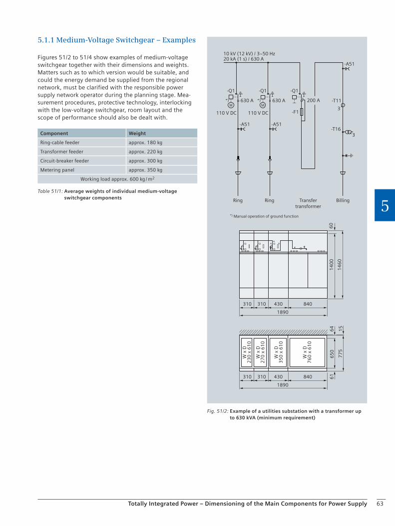
63Totally Integrated Power – Dimensioning of the Main Components for Power Supply
5
5.1.1 Medium-Voltage Switchgear – Examples
Figures 51/2 to 51/4 show examples of medium-voltage switchgear together with their dimensions and weights. Matters such as to which version would be suitable, and could the energy demand be supplied from the regional network, must be clarified with the responsible power supply network operator during the planning stage. Mea-surement procedures, protective technology, interlocking with the low-voltage switchgear, room layout and the scope of performance should also be dealt with.
Ring Ring Transfer transformer
Billing
W x
D
W x
D
W x
D
W x
D
*) Manual operation of ground function
110 V DC 110 V DC
14
60
14
00
60
-Q1
630 A
-A51
200 A*)M
3
-Q1 -Q1
-T11
-T16
630 A
-A51
*)M
-A51
1890
310 310 430 840
1890
310 310 430 840
15
64
65
06
1
77
5
23
0 x
61
0
27
0 x
61
0
35
0 x
61
0
76
0 x
61
0
10 kV (12 kV) / 3~50 Hz20 kA (1 s) / 630 A
3-F1
Fig. 51/2: Example of a utilities substation with a transformer up to 630 kVA (minimum requirement)
Table 51/1: Average weights of individual medium-voltage switchgear components
Component Weight
Ring-cable feeder approx. 180 kg
Transformer feeder approx. 220 kg
Circuit-breaker feeder approx. 300 kg
Metering panel approx. 350 kg
Working load approx. 600 kg / m2
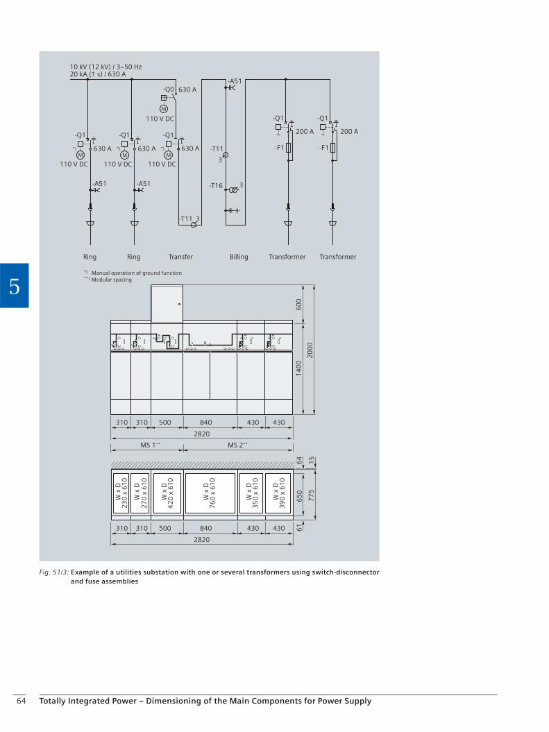
64 Totally Integrated Power – Dimensioning of the Main Components for Power Supply
5
W x
D
W x
D
W x
D
W x
D
Ring Ring Transfer Billing Transformer Transformer
110 V DC 110 V DC 110 V DC
110 V DC
W x
D
W x
D
MS 1** MS 2**
*) Manual operation of ground function**) Modular spacing
23
0 x
61
0
27
0 x
61
0
42
0 x
61
0
76
0 x
61
0
35
0 x
61
0
39
0 x
61
0
-Q1
630 A
-A51
630 A
630 A
*)
M
3
-Q1 -Q1
-Q0
-T11
-T16
630 A
-A51
*)
M*)
M
M
-A51
2820
310 310 500 430 430840
2820
310 310 500 430 430840
20
00
60
01
40
0
15
64
65
06
1
77
5
10 kV (12 kV) / 3~50 Hz20 kA (1 s) / 630 A
3
-T11 3
200 A
-Q1
-F1
200 A
-Q1
-F1
Fig. 51/3: Example of a utilities substation with one or several transformers using switch-disconnector and fuse assemblies

65Totally Integrated Power – Dimensioning of the Main Components for Power Supply
5
Ring Ring Transfer Billing Transformer Transformer
*) Manual operation of ground function**) Modular spacing
110 V DC 110 V DC 110 V DC
110 V DC 110 V DC 110 V DC
W x
D
W x
D
W x
D
W x
D
W x
D
W x
D
-Q1
630 A
-A51
630 A
630 A
*)
M
3
-Q1 -Q1
-Q0
-T11
-T16
630 A
-A51
*)
M*)
M
M
-A51
2820
310 310 500
MS 1** MS 2**
430 430840
2820
310 310 500 430 430840
20
00
60
01
40
0
15
64
65
06
1
77
5
10 kV (12 kV) / 3~50 Hz20 kA (1 s) / 630 A
3
-T21
3
-T21
3
-T11
630 A
630 A
-Q1
-Q0
M
630 A
630 A
-Q1
-Q0
M
3
23
0 x
61
0
27
0 x
61
0
42
0 x
61
0
76
0 x
61
0
35
0 x
61
0
35
0 x
61
0
Fig. 51/4: Example of a utilities substation with one or several transformers using circuit-breakers

66 Totally Integrated Power – Dimensioning of the Main Components for Power Supply
5
5.1.2 Medium-voltage Switchgear Design
Gas-insulated switchgear should be used for the medium-voltage utilities substation. The advantages of gas-insu-lated switchgear are:
Low space requirements (up to approx. 70 % savings with 20 kV) compared to air-insulated switchgear
Smaller transportation size and consequently easier shipping
Increased safety of operation due to hermetically sealed primary switchgear section (adverse impact such as dirt, small animals, contact, condensation are excluded due to the encapsulation)
Maintenance-free primary section (no lubrication and readjustment necessary)
Better eco balance than air-insulated switchgear with regard to the service life
Operator protection:
The gas-insulated switchgear is safe to touch thanks to its grounded metal enclosure.
HV HRC fuses and cable terminations are only accessible if branch circuits are grounded.
Operation is only possible if the enclosure is fully sealed (and any doors closed).
Maintenance-free pressure absorption system, laid out as “special cooling system” reduces pressure-related and thermal impacts of an arc fault so that personnel and building will be safe (Fig. 51/5).
Extendibility:
The switchgear should be extendible with a minimum time expense. A modular system with ordering options for busbar extensions on the right, left or both sides provides the best prerequisite for this:
Individual panels and panel blocks can be mounted side-by-side and extended as desired – no gas work required on site
Low-voltage compartment is available in two heights, wired to the switchgear panel by means of plug connectors
All panels can be replaced at any time
Installation site:
The switchgear is to be used indoors in compliance with IEC 61936 (Power installations exceeding 1 kV a.c.) and VDE 0101. A distinction is made between:
Switchgear in locations with no access from the public, outside closed off electrical operating areas. Switchgear enclosures can only be removed with the aid of tools and operation by unqualified personnel must be prevented.
Closed electrical operating areas: A closed electrical operating area is a room or location used solely for the operation of electrical switchgear and is kept locked. Access is only to electrically skilled persons and electrically instructed persons; unqualified personnel however only when accompanied by electrically skilled or instructed persons.
Operating and maintenance areas
These are corridors, connecting passages, access areas, transportation and escape routes.
Corridors and access areas must be sufficiently dimensioned for work, operation and transportation of components.
The corridors must have a minimum width of 800 mm.
Corridor width must not be obstructed by equipment protruding into the corridor, such as permanently installed drives or switchgear trucks in disconnected position.
The width of the escape route must be at least 500 mm, even if removable parts or fully open doors protrude into the escape route.
Switchgear panel or cubicle doors should close in the escape direction.
For mounting and maintenance work behind enclosed units (stand-alone), a passage width of 500 mm is sufficient.
A minimum height of 2,000 mm below ceilings, covers or enclosures, except for cable basements is required.
Exits must be arranged in such a way that the escape route in the room has a width ≥ 1,000 mm and does not exceed 20 m for rated voltages up to 52 kV. This requirement does not apply to walk-in busbar or cable conduits or ducts.
If operator corridors do not exceed 10 m, one exit is sufficient. If the escape route is longer than 10 m, an (emergency) exit is required at both ends.
Fixed ladders or similar facilities are permissible as emergency exits in escape routes.
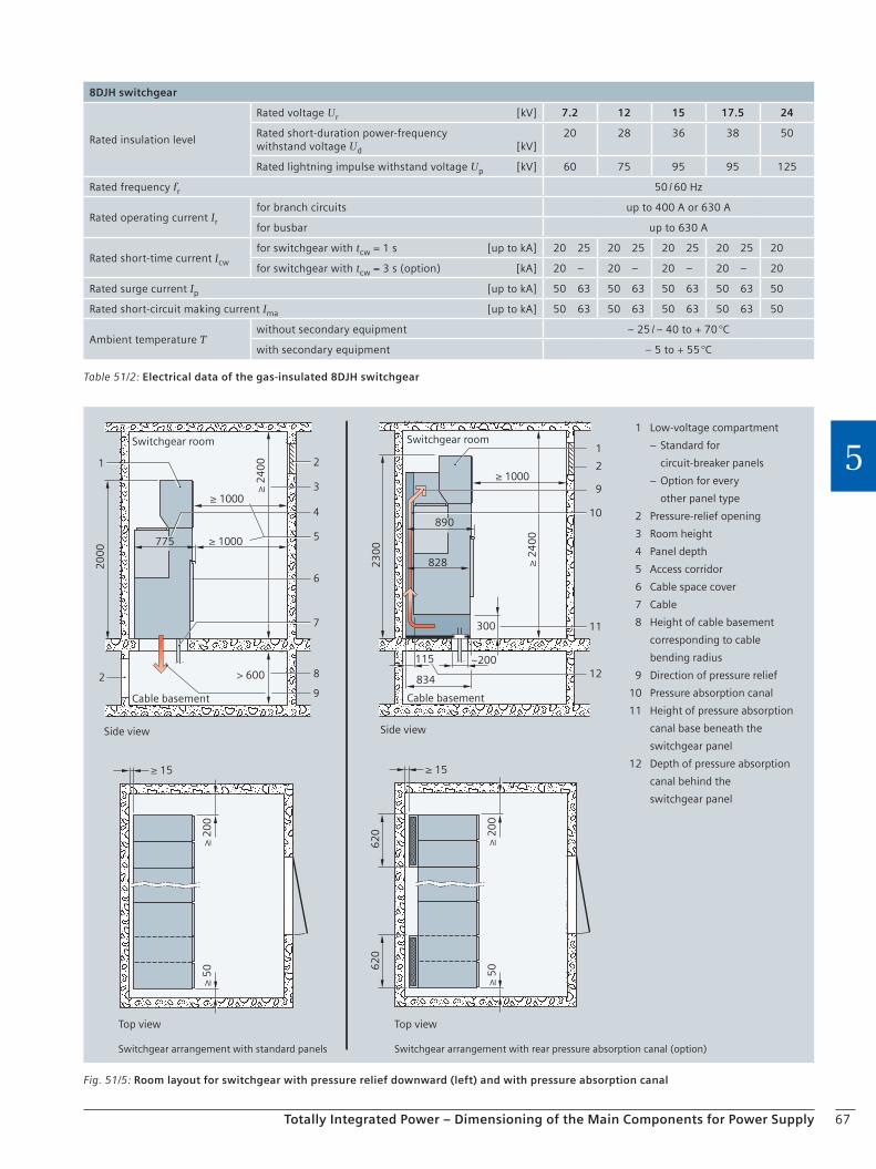
67Totally Integrated Power – Dimensioning of the Main Components for Power Supply
5
Table 51/2: Electrical data of the gas-insulated 8DJH switchgear
8DJH switchgear
Rated insulation level
Rated voltage Ur [kV] 7.2 12 15 17.5 24
Rated short-duration power-frequency withstand voltage Ud [kV]
20 28 36 38 50
Rated lightning impulse withstand voltage Up [kV] 60 75 95 95 125
Rated frequency fr 50 / 60 Hz
Rated operating current Ir
for branch circuits up to 400 A or 630 A
for busbar up to 630 A
Rated short-time current Icw
for switchgear with tcw = 1 s [up to kA] 20 25 20 25 20 25 20 25 20
for switchgear with tcw = 3 s (option) [kA] 20 – 20 – 20 – 20 – 20
Rated surge current Ip [up to kA] 50 63 50 63 50 63 50 63 50
Rated short-circuit making current Ima [up to kA] 50 63 50 63 50 63 50 63 50
Ambient temperature Twithout secondary equipment – 25 / – 40 to + 70 °C
with secondary equipment – 5 to + 55 °C
Fig. 51/5: Room layout for switchgear with pressure relief downward (left) and with pressure absorption canal
1 Low-voltage compartment
– Standard for
circuit-breaker panels
– Option for every
other panel type
2 Pressure-relief opening
3 Room height
4 Panel depth
5 Access corridor
6 Cable space cover
7 Cable
8 Height of cable basement
corresponding to cable
bending radius
9 Direction of pressure relief
10 Pressure absorption canal
11 Height of pressure absorption
canal base beneath the
switchgear panel
12 Depth of pressure absorption
canal behind the
switchgear panel
Side view Side view
Switchgear room
Cable basement
Switchgear room
Cable basement
Switchgear arrangement with standard panels Switchgear arrangement with rear pressure absorption canal (option)
Top view Top view
≥ 1000775
≥ 2
40
0
> 600
20
00
≥ 10003
4
5
6
2
7
2 8
1
115
834
300
828
890
23
00
2
9
10
11
12
1
~200
≥ 2
40
0
≥ 1000
≥ 2
00
≥ 5
0
≥ 15 ≥ 15
≥ 5
0≥
20
0
62
06
20
9
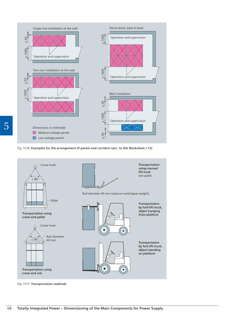
68 Totally Integrated Power – Dimensioning of the Main Components for Power Supply
5
Operation and supervision
Operation and supervision
Single-row installation at the wall
Two-row installation at the wall
Operation and supervision
Wall installation
Operation and supervision
Medium-voltage panels
Dimensions in millimeter
Low-voltage panels
Operation and supervision
Stand-alone, back to back≥
50
≥ 1
00
0≥
10
00
≥ 1
00
0
≥ 1
00
0≥
10
00
≥ 5
0
≥ 5
0≥
50
Fig. 51/6: Examples for the arrangement of panels and corridors (acc. to AGI Worksheet J 12)
Crane hook
Pallet
Transportation usingcrane and pallet
Crane hook
Rod diameter40 mm
Transportation usingcrane and rod
Transportationby fork-lift truck,object hangingfrom platform
Transportationusing manuallift truckw/o pallet
Rod diameter 40 mm (observe switchgear weight)
Transportationby fork-lift truck,object standingon platform
< 90 °
< 90 °
Fig. 51/7: Transportation methods

69Totally Integrated Power – Dimensioning of the Main Components for Power Supply
5
5.2 Pressure Development in Switchgear RoomsIn case of a fault within a gas-insulated switchgear station, an arcing fault can occur which strongly heats the sur-rounding gas resulting in an extreme rise in pressure. The extent of the pressure rise depends on the room geometry, the pressure relief openings and arcing fault energy.
The consequences of such a (rare) fault can be extremely serious not only for the operating personnel, but also for the room. For this reason, appropriate measures must be taken for pressure relief, such as pressure relief openings, canals, absorbers or coolers (Fig. 52/1, Fig. 52/2). The actual pressure load capability of the building as well as its structural characteristics must have been inspected and approved by the statics engineer.
There is a simplified pressure calculation according to Pigler for the 8DJH switchgear (Fig. 52/3). It provides a good approximation for closed rooms when the pressure increases uniformly throughout the room. However, the result of the pressure calculation does not provide any information on the pressure load capability of the building and its structural components (e.g. doors and windows). They must be designed by the statics engineer. Responsi-bility cannot be assumed for any damage resulting from arcing fault.
Fig. 52/1: Pressure relief downward
Fig. 52/3: Example of stationary excess pressure resulting from internal arcing faults
Pressure calculation according to Pigler for the 8DJ/H switchgear type without absorber
Exce
ss p
ress
ure
[p
] in
hPa
Time [t] in msRoom volume [VR] in m3: 50
Cross section of pressure relief opening [Arel] in m2: 1
Short-circuit current [IK“] in kA: 16 Maximum pressure [Pmax]: 10.9 hPa after 99 ms
0
2
4
6
8
10
12
100 200 300 400 500 600 700 800 900 1000
Fig. 52/2: Pressure relief upward with pressure absorber
Definitions
The free building volume corresponds to the volume of the room in which pressure relief takes place minus the volume of the switchgear itself and any other interior fittings.
If pressure is relieved into the cable basement, the free building volume corresponds to the cable basement volume.
If there is a pressure compensation opening from the cable basement into the switchgear room, both room volumes may be combined as an approximation. In this case, the opening for compensation between the two room volumes must be equal to the pressure relief opening to the outside.
In case of highly complex geometries or higher short-circuit powers, it is necessary to perform a detailed pressure calculation with 3D finite elements which also takes the dynamic pressure development into account.
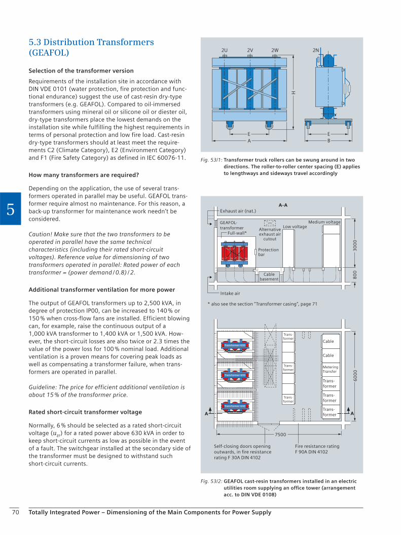
70 Totally Integrated Power – Dimensioning of the Main Components for Power Supply
5
5.3 Distribution Transformers (GEAFOL)
Selection of the transformer version
Requirements of the installation site in accordance with DIN VDE 0101 (water protection, fire protection and func-tional endurance) suggest the use of cast-resin dry-type transformers (e.g. GEAFOL). Compared to oil-immersed transformers using mineral oil or silicone oil or diester oil, dry-type transformers place the lowest demands on the installation site while fulfilling the highest requirements in terms of personal protection and low fire load. Cast-resin dry-type transformers should at least meet the require-ments C2 (Climate Category), E2 (Environment Category) and F1 (Fire Safety Category) as defined in IEC 60076-11.
How many transformers are required?
Depending on the application, the use of several trans-formers operated in parallel may be useful. GEAFOL trans-former require almost no maintenance. For this reason, a back-up transformer for maintenance work needn’t be considered.
Caution! Make sure that the two transformers to be operated in parallel have the same technical characteristics (including their rated short-circuit voltages). Reference value for dimensioning of two transformers operated in parallel: Rated power of each transformer = (power demand / 0.8) / 2.
Additional transformer ventilation for more power
The output of GEAFOL transformers up to 2,500 kVA, in degree of protection IP00, can be increased to 140 % or 150 % when cross-flow fans are installed. Efficient blowing can, for example, raise the continuous output of a 1,000 kVA transformer to 1,400 kVA or 1,500 kVA. How-ever, the short-circuit losses are also twice or 2.3 times the value of the power loss for 100 % nominal load. Additional ventilation is a proven means for covering peak loads as well as compensating a transformer failure, when trans-formers are operated in parallel.
Guideline: The price for efficient additional ventilation is about 15 % of the transformer price.
Rated short-circuit transformer voltage
Normally, 6 % should be selected as a rated short-circuit voltage (uzr) for a rated power above 630 kVA in order to keep short-circuit currents as low as possible in the event of a fault. The switchgear installed at the secondary side of the transformer must be designed to withstand such short-circuit currents.
Exhaust air (nat.)
Intake air
Cable
Cable
Trans-former
Trans-former
Trans-former
Metering Transfer
Transformer
* also see the section “Transformer casing“, page 71
GEAFOL-transformer Alternative
exhaust air cutout
Low voltageMedium voltage
Protectionbar
Full-wall*
Cablebasement
Self-closing doors opening outwards, in fire resistance rating F 30A DIN 4102
Fire resistance ratingF 90A DIN 4102
Trans-former
Trans-former
Trans-former
Transformer
Transformer
A
30
00
80
06
00
0
A
A-A
7500
1U 1V 1W
630
630
630
Fig. 53/2: GEAFOL cast-resin transformers installed in an electric utilities room supplying an office tower (arrangement acc. to DIN VDE 0108)
H
E EBA
2U 2V 2W 2N
Fig. 53/1: Transformer truck rollers can be swung around in two directions. The roller-to-roller center spacing (E) applies to lengthways and sideways travel accordingly

71Totally Integrated Power – Dimensioning of the Main Components for Power Supply
5
Example:
A 1,000 kVA transformer with a rated short-circuit voltage of 4 % supplies the 0.4 kV secondary network with approx. 36 kA in case of a short circuit.
The same transformer with a rated short-circuit voltage of 6 % only supplies the 0.4 kV secondary network with approx. 24 kA in case of a short circuit.
Vector group
DYN5 (standard vector group in Germany)
DYN11 (frequently used vector group in Asia as well as in Europe)
Note: Vector groups Dyn5 and Dyn11 have the same price.
No-load losses – reduced losses
Following the guidelines for sustainable construction of the German Ministry for Traffic, Building and Residential Development and with regard to the energy passport, transformers with reduced losses should be preferred.
The economic efficiency of such a transformer can be verified by means of a loss evaluation.
Guideline: If the cost factor for a kilowatt hour exceeds 2,000 EUR per annum, the increased cost for a transformer with reduced losses pays off within five years.
Noise – acoustic power level
Noise caused by transformers can be reduced as follows:
Use of transformers with reduced no-load losses; this reduces the acoustic power level by approx. 8 dB.
Reduction of structure-borne noise by using metal-rubber rails and special transformer bedding. (Note: The transformer noise itself is not changed by this).
Decoupling of connected busbars to minimize structure-borne noise (e.g. by using elastic tapes).
Temperature monitoring
Transformers are equipped with a temperature monitoring system. For a three-phase transformer, this system consists of three series-connected PTC sensors – one per phase – and a tripping unit.
It is useful to provide for an additional temperature sensor loop for an alarm, which can be wired to the same tripping unit.
Transformer casing
The transformer casing serves as contact protection in electrical operating areas which are freely accessible. With IP23 or higher, it is possible to reduce the acoustic power level by up to 3 dB.
Conditions for installation – room layout
GEAFOL cast-resin transformers can be installed in the same room as medium- and low-voltage switchgear with-out any extra precautions. For switchgear that come within the scope of Elt Bau VO, the electric utilities room must be enclosed by fireproof walls and doors (walls in fire resis-tance rating F90A, doors in F30A).
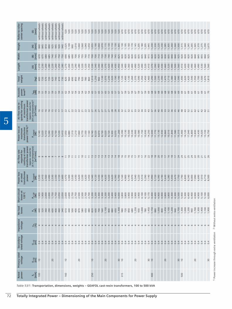
72 Totally Integrated Power – Dimensioning of the Main Components for Power Supply
5
1) P
ow
er in
crea
se t
hro
ug
h e
xtra
ven
tila
tio
n
2) W
ith
ou
t ex
tra
ven
tila
tio
n
Table 53/1: Transportation, dimensions, weights – GEAFOL cast-resin transformers, 100 to 500 kVA
Rat
ed
p
ow
er
S r[k
VA
]
Prim
ary
rate
d
volt
age
Ur
OS
[kV
]
Seco
nd
ary
rate
d v
olt
age
Ur
US
[kV
]
Imp
ed
ance
vo
ltag
e
uzr
[ %]
No
-lo
ad
loss
es
P o[W
]
Sho
rt-c
ircu
it
loss
es
at
12
0 °C
P k 1
20
[W]
Pow
er
loss
at r
ate
d
tran
sfo
rme
r p
ow
er
P v (r
ate
d)
[W]
Air
flo
w r
ate
req
uir
ed
fo
r co
oli
ng
at
rate
d
tran
sfo
rme
r p
ow
er
(ap
pro
x. v
alu
es
for
25
°C
air
te
mp
era
ture
)
[m3 / m
in]
Pow
er
loss
at
max
imu
m
tran
sfo
rme
r p
ow
er
(15
0 %
)1)
P v (m
ax)
[W]
Air
flo
w r
ate
re
-q
uir
ed
fo
r co
oli
ng
at
max
imu
m
tran
sfo
rme
r p
ow
er
(ap
pro
x. v
alu
es
for
25
°C a
ir t
em
pe
ratu
re)1
)
[m3 / m
in]
Aco
ust
ic
po
we
r le
vel2
)
L WA
[dB
]
Tota
l w
eig
ht
[kg
]
Len
gth
(A)
[mm
]
Wid
th
(B)
[mm
]
He
igh
t
(H)
[mm
]
Ro
lle
r-to
-ro
lle
r ce
nte
r sp
acin
g
(E)
[mm
]
10
01
00
.44
44
01
,90
02
,53
08
5,1
40
16
59
60
01
,21
06
70
84
0w
ith
ou
t w
hee
ls0
.44
32
01
,90
02
,41
08
5,0
20
15
51
72
01
,23
06
75
84
5w
ith
ou
t w
hee
ls0
.46
36
02
,00
02
,56
08
5,3
10
16
59
57
01
,20
06
80
81
0w
ith
ou
t w
hee
ls0
.46
29
02
,00
02
,49
08
5,2
40
16
51
72
01
,28
06
85
89
0w
ith
ou
t w
hee
ls2
00
.44
60
01
,75
02
,53
08
4,9
30
15
59
62
01
,22
07
40
92
5w
ith
ou
t w
hee
ls0
.44
40
01
,75
02
,33
07
4,7
30
15
51
74
01
,26
07
45
94
5w
ith
ou
t w
hee
ls0
.46
46
02
,05
02
,72
09
5,5
30
17
59
61
01
,25
07
50
92
0w
ith
ou
t w
hee
ls0
.46
34
02
,05
02
,60
08
5,4
10
17
51
73
01
,28
07
50
94
0w
ith
ou
t w
hee
ls1
60
10
0.4
46
10
2,6
00
3,4
70
11
7,0
50
22
62
82
01
,27
06
90
1,0
25
52
00
.44
44
02
,60
03
,30
01
06
,88
02
15
49
60
1,2
60
68
51
,10
05
20
0.4
65
00
2,7
50
3,5
30
11
7,3
10
22
62
69
01
,22
06
90
99
05
20
0.4
64
00
2,7
50
3,4
30
11
7,2
10
22
54
85
01
,29
07
00
1,0
10
52
02
00
.44
87
02
,50
03
,62
01
17
,06
02
26
27
90
1,2
80
74
51
,06
05
20
0.4
45
80
2,5
00
3,3
30
10
6,7
70
21
54
92
01
,32
07
55
1,0
60
52
00
.46
65
02
,70
03
,62
01
17
,33
02
26
27
80
1,3
20
76
01
,04
05
20
0.4
64
80
2,7
00
3,4
50
11
7,1
60
22
54
86
01
,35
07
70
1,0
50
52
02
50
10
0.4
48
20
3,2
00
4,3
40
13
8,7
40
27
65
1,0
10
1,3
30
70
01
,05
55
20
0.4
46
00
3,2
00
4,1
20
13
8,5
20
26
57
1,2
50
1,3
40
70
01
,19
05
20
0.4
67
00
3,3
00
4,3
30
13
8,8
70
27
65
96
01
,34
07
10
1,0
60
52
00
.46
56
03
,30
04
,19
01
38
,73
02
75
71
,13
01
,39
07
20
1,0
70
52
02
00
.44
1,1
00
3,2
00
4,6
20
14
9,0
20
27
65
1,0
70
1,3
70
73
01
,11
55
20
0.4
48
00
3,2
00
4,3
20
13
8,7
20
27
57
1,2
30
1,4
20
74
01
,13
05
20
0.4
68
80
3,4
00
4,6
20
14
9,3
00
28
65
1,0
20
1,3
90
74
01
,11
05
20
0.4
66
50
3,4
00
4,3
90
14
9,0
70
28
57
1,1
90
1,4
30
74
51
,13
05
20
30
0.4
61
,30
04
,00
05
,70
01
81
1,2
00
34
67
1,1
90
1,4
50
82
51
,36
55
20
31
51
00
.44
98
03
,80
05
,16
01
61
0,3
90
32
67
1,1
20
1,3
40
82
01
,13
06
70
0.4
47
20
3,8
00
4,9
00
15
10
,13
03
15
91
,40
01
,40
08
20
1,1
95
67
00
.46
85
03
,90
05
,14
01
61
0,5
00
32
67
1,1
30
1,3
60
82
01
,16
06
70
0.4
66
80
3,9
00
4,9
70
15
10
,33
03
15
91
,26
01
,40
08
20
1,1
70
67
02
00
.44
1,2
50
3,9
00
5,5
40
17
10
,90
03
36
71
,37
01
,49
08
35
1,1
45
67
00
.44
93
03
,90
05
,22
01
61
0,5
80
32
59
1,5
90
1,5
20
83
51
,20
56
70
0.4
61
,00
04
,10
05
,51
01
71
1,1
50
34
67
1,3
50
1,4
90
83
51
,18
06
70
0.4
67
80
4,1
00
5,2
90
16
10
,93
03
35
91
,45
01
,52
08
40
1,2
05
67
03
00
.46
1,4
50
5,1
70
7,1
40
22
14
,25
04
36
91
,46
01
,41
09
15
1,4
45
67
04
00
10
0.4
41
,15
04
,40
05
,99
01
81
2,0
40
37
68
1,2
90
1,3
70
82
01
,23
06
70
0.4
48
80
4,4
00
5,7
20
18
11
,77
03
66
01
,50
01
,39
08
20
1,3
30
67
00
.46
1,0
00
4,9
00
6,3
90
20
13
,13
04
06
81
,23
01
,40
08
20
1,2
20
67
00
.46
80
04
,90
06
,19
01
91
2,9
30
39
60
1,3
90
1,4
30
82
01
,23
06
70
20
0.4
41
,45
03
,80
05
,63
01
71
0,8
60
33
68
1,4
70
1,4
60
83
01
,28
56
70
0.4
41
,10
03
,80
05
,28
01
61
0,5
10
32
60
1,7
10
1,5
20
83
51
,30
56
70
0.4
61
,20
04
,30
05
,93
01
81
1,8
40
36
68
1,3
80
1,4
90
84
01
,26
06
70
0.4
69
40
4,3
00
5,6
70
17
11
,58
03
56
01
,46
01
,50
08
40
1,2
60
67
03
00
.46
1,7
00
5,5
00
7,7
50
24
15
,31
04
66
91
,59
01
,56
09
25
1,5
00
67
05
00
10
0.4
41
,30
05
,90
07
,79
02
41
5,9
00
48
69
1,4
90
1,4
10
82
01
,31
56
70
0.4
41
,00
05
,30
06
,83
02
11
4,1
20
43
61
1,6
20
1,4
20
82
01
,34
06
70
0.4
61
,20
06
,40
08
,24
02
51
7,0
40
52
69
1,4
20
1,4
50
82
01
,24
56
70
0.4
69
60
6,4
00
8,0
00
24
16
,80
05
16
11
,54
01
,49
08
20
1,2
65
67
02
00
.44
1,7
00
4,9
00
7,0
90
22
13
,83
04
26
91
,55
01
,46
08
40
1,3
65
67
00
.44
1,3
00
4,9
00
6,6
90
20
13
,43
04
16
11
,70
01
,49
08
45
1,3
70
67
00
.46
1,4
00
5,1
00
7,0
10
21
14
,02
04
26
91
,50
01
,53
08
55
1,2
75
67
00
.46
1,1
00
5,1
00
6,7
10
21
13
,72
04
26
11
,67
01
,56
08
60
1,2
90
67
03
00
.46
1,9
00
6,0
00
8,5
00
26
16
,75
05
17
01
,81
01
,56
09
25
1,6
15
67
0
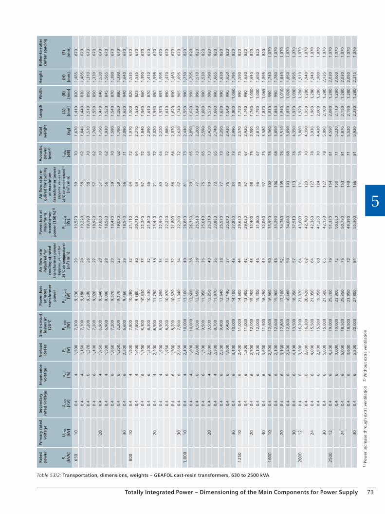
73Totally Integrated Power – Dimensioning of the Main Components for Power Supply
5
1) P
ow
er in
crea
se t
hro
ug
h e
xtra
ven
tila
tio
n
2) W
ith
ou
t ex
tra
ven
tila
tio
n
Table 53/2: Transportation, dimensions, weights – GEAFOL cast-resin transformers, 630 to 2500 kVA
Rat
ed
p
ow
er
S r[k
VA
]
Prim
ary
rate
d
volt
age
Ur
OS
[kV
]
Seco
nd
ary
rate
d v
olt
age
Ur
US
[kV
]
Imp
ed
ance
vo
ltag
e
uzr
[ %]
No
-lo
ad
loss
es
P o[W
]
Sho
rt-c
ircu
it
loss
es
at
12
0 °C
P k 1
20
[W]
Pow
er
loss
at r
ate
d
tran
sfo
rme
r p
ow
er
P v (r
ate
d)
[W]
Air
flo
w r
ate
req
uir
ed
fo
r co
oli
ng
at
rate
d
tran
sfo
rme
r p
ow
er
(ap
pro
x. v
alu
es
for
25
°C
air
te
mp
era
ture
)
[m3 / m
in]
Pow
er
loss
at
max
imu
m
tran
sfo
rme
r p
ow
er
(15
0 %
)1)
P v (m
ax)
[W]
Air
flo
w r
ate
re
-q
uir
ed
fo
r co
oli
ng
at
max
imu
m
tran
sfo
rme
r p
ow
er
(ap
pro
x. v
alu
es
for
25
°C a
ir t
em
pe
ratu
re)1
)
[m3 / m
in]
Aco
ust
ic
po
we
r le
vel2
)
L WA
[dB
]
Tota
l w
eig
ht
[kg
]
Len
gth
(A)
[mm
]
Wid
th
(B)
[mm
]
He
igh
t
(H)
[mm
]
Ro
lle
r-to
-ro
lle
r ce
nte
r sp
acin
g
(E)
[mm
]
63
01
00
.44
1,5
00
7,3
00
9,5
30
29
19
,57
05
97
01
,67
01
,41
08
20
1,4
85
67
0
0.4
41
,15
07
,30
09
,18
02
81
9,2
20
58
62
1,8
40
1,4
40
82
01
,48
56
70
0.4
61
,37
07
,20
09
,29
02
81
9,1
90
58
70
1,5
70
1,5
10
85
01
,31
06
70
0.4
61
,10
07
,20
09
,02
02
71
8,9
20
57
62
1,7
60
1,5
50
85
01
,33
06
70
20
0.4
41
,95
06
,90
09
,54
02
91
9,0
30
57
70
1,7
90
1,4
70
84
01
,53
06
70
0.4
41
,50
06
,90
09
,09
02
81
8,5
80
56
62
1,9
30
1,5
20
84
51
,56
56
70
0.4
61
,65
07
,20
09
,57
02
91
9,4
70
59
70
1,5
90
1,5
40
87
01
,38
06
70
0.4
61
,25
07
,20
09
,17
02
81
9,0
70
58
62
1,7
80
1,5
80
88
01
,39
06
70
30
0.4
62
,20
06
,60
09
,46
02
91
8,5
40
56
71
2,0
90
1,6
20
94
01
,64
06
70
80
01
00
.44
1,8
00
7,8
00
10
,38
03
22
1,1
10
64
72
1,9
70
1,5
00
82
01
,53
56
70
0.4
41
,40
07
,80
09
,98
03
02
0,7
10
63
64
2,2
10
1,5
30
82
51
,53
56
70
0.4
61
,70
08
,30
01
0,8
30
33
22
,24
06
77
21
,84
01
,56
08
60
1,3
90
67
0
0.4
61
,30
08
,30
01
0,4
30
32
21
,84
06
66
42
,09
01
,61
08
70
1,4
10
67
0
20
0.4
42
,40
08
,50
01
1,7
50
36
23
,44
07
17
22
,02
01
,55
08
50
1,5
95
67
0
0.4
41
,90
08
,50
01
1,2
50
34
22
,94
06
96
42
,22
01
,57
08
55
1,5
95
67
0
0.4
61
,95
08
,20
01
0,9
70
33
22
,25
06
77
21
,88
01
,61
08
90
1,4
70
67
0
0.4
61
,50
08
,20
01
0,5
20
32
21
,80
06
66
42
,07
01
,62
08
90
1,4
60
67
0
30
0.4
62
,65
07
,90
01
1,3
40
34
22
,20
06
77
22
,62
01
,74
09
65
1,6
95
67
0
1,0
00
10
0.4
42
,10
01
0,0
00
13
,10
04
02
6,8
50
81
73
2,4
40
1,5
50
99
01
,73
08
20
0.4
41
,60
01
0,0
00
12
,60
03
82
6,3
50
79
65
2,8
50
1,6
20
99
01
,79
58
20
0.4
62
,00
09
,50
01
2,4
50
38
25
,51
07
77
32
,26
01
,64
09
90
1,5
10
82
0
0.4
61
,50
09
,50
01
1,9
50
36
25
,01
07
56
52
,59
01
,68
09
90
1,5
30
82
0
20
0.4
42
,80
09
,50
01
3,2
50
40
26
,31
07
97
32
,42
01
,57
09
90
1,7
90
82
0
0.4
42
,30
08
,70
01
1,8
70
36
23
,83
07
26
52
,74
01
,68
09
90
1,6
65
82
0
0.4
62
,30
09
,40
01
2,6
40
38
25
,57
07
77
32
,25
01
,63
09
90
1,6
30
82
0
0.4
61
,80
09
,40
01
2,1
40
37
25
,07
07
66
52
,43
01
,64
09
90
1,6
50
82
0
30
0.4
63
,10
01
0,0
00
14
,10
04
32
7,8
50
84
73
2,9
90
1,8
00
1,0
60
1,7
95
82
0
12
50
10
0.4
62
,40
01
1,0
00
14
,50
04
42
9,6
30
89
75
2,5
70
1,7
20
99
01
,59
08
20
0.4
61
,80
01
1,0
00
13
,90
04
22
9,0
30
87
67
2,9
20
1,7
40
99
01
,63
08
20
20
0.4
62
,70
01
2,0
00
15
,90
04
83
2,4
00
98
75
2,5
90
1,7
60
1,0
00
1,6
40
82
0
0.4
62
,10
01
2,0
00
15
,30
04
63
1,8
00
96
67
2,8
10
1,7
90
1,0
00
1,6
50
82
0
30
0.4
63
,60
01
1,5
00
16
,25
04
93
2,0
60
97
75
3,5
80
1,8
70
1,0
65
1,8
95
82
0
16
00
10
0.4
62
,80
01
2,6
00
16
,66
05
03
3,9
90
10
27
63
,36
01
,81
09
90
1,7
40
1,0
70
0.4
62
,10
01
2,6
00
15
,96
04
83
3,2
90
10
06
83
,85
01
,84
09
90
1,7
80
1,0
70
20
0.4
63
,10
01
2,8
00
17
,18
05
23
4,7
80
10
57
63
,51
01
,84
01
,01
01
,84
01
,07
0
0.4
62
,40
01
2,8
00
16
,48
05
03
4,0
80
10
36
83
,89
01
,87
01
,02
01
,85
01
,07
0
30
0.4
64
,10
01
3,5
00
18
,95
05
73
7,5
10
11
37
64
,35
01
,97
01
,09
01
,99
51
,07
0
20
00
12
0.4
63
,50
01
6,2
00
21
,32
06
44
3,6
00
13
17
83
,86
01
,92
01
,28
01
,91
01
,07
0
0.4
62
,60
01
6,2
00
20
,42
06
24
2,7
00
12
97
04
,39
01
,95
01
,28
01
,94
01
,07
0
24
0.4
64
,00
01
5,5
00
21
,05
06
44
2,3
60
12
77
83
,93
01
,96
01
,28
01
,94
01
,07
0
0.4
62
,90
01
5,5
00
19
,95
06
04
1,2
60
12
47
04
,43
02
,00
01
,28
01
,98
01
,07
0
30
0.4
65
,00
01
5,0
00
21
,50
06
54
2,1
30
12
77
85
,09
02
,10
01
,28
02
,13
51
,07
0
25
00
12
0.4
64
,30
01
9,0
00
25
,20
07
65
1,3
30
15
48
14
,55
02
,08
01
,28
02
,03
01
,07
0
0.4
63
,00
01
9,0
00
23
,90
07
25
0,0
30
15
07
15
,23
02
,11
01
,28
02
,06
01
,07
0
24
0.4
65
,00
01
8,5
00
25
,35
07
65
0,7
90
15
38
14
,87
02
,15
01
,28
02
,03
01
,07
0
0.4
63
,60
01
8,5
00
23
,95
07
24
9,3
90
14
97
15
,52
02
,19
01
,28
02
,05
01
,07
0
30
0.4
65
,80
02
0,0
00
27
,80
08
45
5,3
00
16
68
15
,92
02
,28
01
,28
02
,21
51
,07
0
74
Checklist
Totally Integrated Power – Dimensioning of the Main Components for Power Supply
5
GEAFOL distribution transformerBesides the regulations, standards and guidelines listed in section 2.3, the international standard IEC 60076-11 for dry-type transformers and specifications made by the local power distribution network operator must be observed.
Rated power . . . . . . . . . . . . . . . . . . . . kVA (from power demand calculation)
Number of transformers . . . . . . . . . . . . . . . . . . . . (from power demand calculation)
Primary rated voltage . . . . . . . . . . . . . . . . . . . . kV (specified by power supply company)
Secondary rated voltage (no-load) . . . . . . . . . . . . . . . . . . . . kV (low-voltage level)
Tapping of primary winding c Yes c No
Rated frequency 50 Hz
Rated short-circuit voltage c 4 % c 6 %
Type Cast-resin dry-type transformers
Vector group c DYN5 c DYN11
Extra ventilation on the transformer c Yes c No
Make-proof grounding switch on the transformer c Yes c No
No-load losses and noise c Reduced (useful)
c Not reduced
Temperature monitoring c Systems for alarm and tripping
c System for fan control
Insulation against structure-borne noise c Yes (transformer bedding) c No
Transformer casing c Yes
c IP20 degree of protection – indoors
c IP23 degree of protection – indoors
c IP23 degree of protection – outdoors
c No
High level of operational safety and long service life c Partial discharge less than 5pC at twice the rated voltage
Maximum ambient temperature (standard 40 °C) . . . . . . . . . . °C
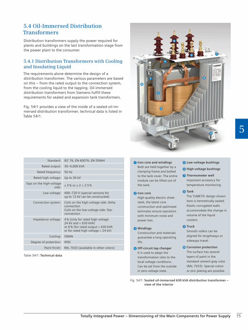
75Totally Integrated Power – Dimensioning of the Main Components for Power Supply
5
5.4 Oil-Immersed Distribution TransformersDistribution transformers supply the power required for plants and buildings on the last transformation stage from the power plant to the consumer.
5.4.1 Distribution Transformers with Cooling and Insulating Liquid
The requirements alone determine the design of a distribution transformer. The various parameters are based on this – from the rated output to the connection system, from the cooling liquid to the tapping. Oil-immersed distribution transformers from Siemens fulfill these requirements for sealed and expansion tank transformers.
Fig. 54/1 provides a view of the inside of a sealed oil-im-mersed distribution transformer; technical data is listed in Table 54/1.
Table 54/1: Technical data
Standard: IEC 76, EN 60076, EN 50464
Rated output: 30–4,000 kVA
Rated frequency: 50 Hz
Rated high voltage: Up to 36 kV
Taps on the high-voltage side:
± 5 % or ± 2 × 2.5 %
Low voltage: 400–720 V (special versions for up to 12 kV can be constructed)
Connection system: Coils on the high-voltage side: Delta connectionCoils on the low-voltage side: Star connection
Impedance voltage: 4 % (only for rated high voltage 24 kV and < 630 kVA)or 6 % (for rated output > 630 kVA or for rated high voltage > 24 kV)
Cooling: ONAN
Degree of protection: IP00
Paint finish: RAL 7033 (available in other colors)
Fig. 54/1: Sealed oil-immersed 630 kVA distribution transformer – view of the interior
Iron core and windings
Both are held together by a
clamping frame and bolted
to the tank cover. The entire
module can be lifted out of
the tank.
Iron core
High-quality electric sheet
steel, the latest core
construction and optimized
laminates ensure operation
with minimum noise and
power loss.
Windings
Construction and materials
guarantee a long operating
life.
Off-circuit tap changer
It is used to adapt the
transformation ratio to the
local voltage conditions.
Can be set from the outside
in zero voltage state.
Low-voltage bushings
High-voltage bushings
Thermometer well
Important accessory for
temperature monitoring.
Tank
The TUMETIC design shown
here is hermetically sealed.
Elastic corrugated walls
accommodate the change in
volume of the liquid
coolant.
Truck
Smooth rollers can be
aligned for lengthways or
sideways travel.
Corrosion protection
The surface has several
layers of paint in the
standard cement gray color
(RAL 7033). Special colors
or zinc plating are possible.
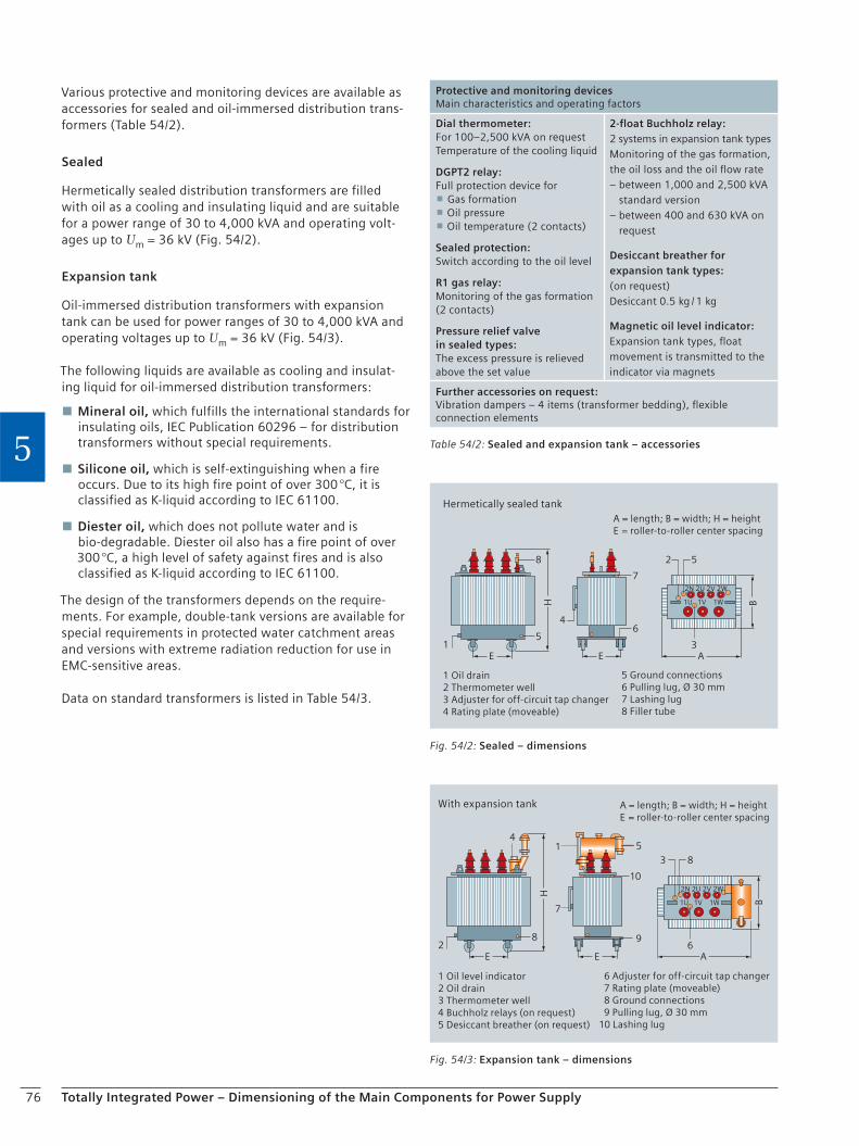
76 Totally Integrated Power – Dimensioning of the Main Components for Power Supply
5
Various protective and monitoring devices are available as accessories for sealed and oil-immersed distribution trans-formers (Table 54/2).
Sealed
Hermetically sealed distribution transformers are filled with oil as a cooling and insulating liquid and are suitable for a power range of 30 to 4,000 kVA and operating volt-ages up to Um = 36 kV (Fig. 54/2).
Expansion tank
Oil-immersed distribution transformers with expansion tank can be used for power ranges of 30 to 4,000 kVA and operating voltages up to Um = 36 kV (Fig. 54/3).
The following liquids are available as cooling and insulat-ing liquid for oil-immersed distribution transformers:
Mineral oil, which fulfills the international standards for insulating oils, IEC Publication 60296 – for distribution transformers without special requirements.
Silicone oil, which is self-extinguishing when a fire occurs. Due to its high fire point of over 300 °C, it is classified as K-liquid according to IEC 61100.
Diester oil, which does not pollute water and is bio-degradable. Diester oil also has a fire point of over 300 °C, a high level of safety against fires and is also classified as K-liquid according to IEC 61100.
The design of the transformers depends on the require-ments. For example, double-tank versions are available for special requirements in protected water catchment areas and versions with extreme radiation reduction for use in EMC-sensitive areas.
Data on standard transformers is listed in Table 54/3.
Hermetically sealed tank
1 Oil drain2 Thermometer well3 Adjuster for off-circuit tap changer4 Rating plate (moveable)
5 Ground connections6 Pulling lug, Ø 30 mm7 Lashing lug8 Filler tube
A = length; B = width; H = heightE = roller-to-roller center spacing
15
8 2 5
4
7
6
3
2N 2U 2V 2W
1U 1V 1WH
E E A
BFig. 54/2: Sealed – dimensions
With expansion tank
1 Oil level indicator2 Oil drain3 Thermometer well4 Buchholz relays (on request)5 Desiccant breather (on request)
6 Adjuster for off-circuit tap changer 7 Rating plate (moveable) 8 Ground connections 9 Pulling lug, Ø 30 mm 10 Lashing lug
A = length; B = width; H = heightE = roller-to-roller center spacing
28
4
3 8
10
96
2N 2U 2V 2W
1U 1V 1W
H
E E A
51
7
B
Fig. 54/3: Expansion tank – dimensions
Table 54/2: Sealed and expansion tank – accessories
Protective and monitoring devicesMain characteristics and operating factors
Dial thermometer:For 100–2,500 kVA on requestTemperature of the cooling liquid
DGPT2 relay:Full protection device for
Gas formation Oil pressure Oil temperature (2 contacts)
Sealed protection:Switch according to the oil level
R1 gas relay:Monitoring of the gas formation(2 contacts)
Pressure relief valve in sealed types:The excess pressure is relieved above the set value
2-float Buchholz relay:2 systems in expansion tank typesMonitoring of the gas formation,the oil loss and the oil flow rate– between 1,000 and 2,500 kVA
standard version– between 400 and 630 kVA on
request
Desiccant breather for expansion tank types:(on request)Desiccant 0.5 kg / 1 kg
Magnetic oil level indicator:Expansion tank types, float movement is transmitted to the indicator via magnets
Further accessories on request:Vibration dampers – 4 items (transformer bedding), flexible connection elements
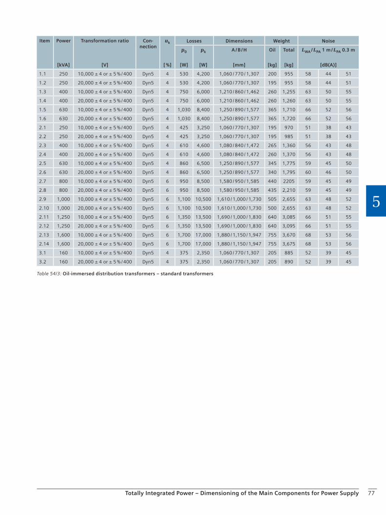
77Totally Integrated Power – Dimensioning of the Main Components for Power Supply
5
Table 54/3: Oil-immersed distribution transformers – standard transformers
Item Power
[kVA]
Transformation ratio
[V]
Con-nection
uk
[ %]
Losses Dimensions Weight Noise
p0
[W]
pk
[W]
A / B / H
[mm]
Oil
[kg]
Total
[kg]
LWA / LPA 1 m / LPA 0.3 m
[dB(A)]
1.1 250 10,000 ± 4 or ± 5 % / 400 Dyn5 4 530 4,200 1,060 / 770 / 1,307 200 955 58 44 51
1.2 250 20,000 ± 4 or ± 5 % / 400 Dyn5 4 530 4,200 1,060 / 770 / 1,307 195 955 58 44 51
1.3 400 10,000 ± 4 or ± 5 % / 400 Dyn5 4 750 6,000 1,210 / 860 / 1,462 260 1,255 63 50 55
1.4 400 20,000 ± 4 or ± 5 % / 400 Dyn5 4 750 6,000 1,210 / 860 / 1,462 260 1,260 63 50 55
1.5 630 10,000 ± 4 or ± 5 % / 400 Dyn5 4 1,030 8,400 1,250 / 890 / 1,577 365 1,710 66 52 56
1.6 630 20,000 ± 4 or ± 5 % / 400 Dyn5 4 1,030 8,400 1,250 / 890 / 1,577 365 1,720 66 52 56
2.1 250 10,000 ± 4 or ± 5 % / 400 Dyn5 4 425 3,250 1,060 / 770 / 1,307 195 970 51 38 43
2.2 250 20,000 ± 4 or ± 5 % / 400 Dyn5 4 425 3,250 1,060 / 770 / 1,307 195 985 51 38 43
2.3 400 10,000 ± 4 or ± 5 % / 400 Dyn5 4 610 4,600 1,080 / 840 / 1,472 265 1,360 56 43 48
2.4 400 20,000 ± 4 or ± 5 % / 400 Dyn5 4 610 4,600 1,080 / 840 / 1,472 260 1,370 56 43 48
2.5 630 10,000 ± 4 or ± 5 % / 400 Dyn5 4 860 6,500 1,250 / 890 / 1,577 345 1,775 59 45 50
2.6 630 20,000 ± 4 or ± 5 % / 400 Dyn5 4 860 6,500 1,250 / 890 / 1,577 340 1,795 60 46 50
2.7 800 10,000 ± 4 or ± 5 % / 400 Dyn5 6 950 8,500 1,580 / 950 / 1,585 440 2205 59 45 49
2.8 800 20,000 ± 4 or ± 5 % / 400 Dyn5 6 950 8,500 1,580 / 950 / 1,585 435 2,210 59 45 49
2.9 1,000 10,000 ± 4 or ± 5 % / 400 Dyn5 6 1,100 10,500 1,610 / 1,000 / 1,730 505 2,655 63 48 52
2.10 1,000 20,000 ± 4 or ± 5 % / 400 Dyn5 6 1,100 10,500 1,610 / 1,000 / 1,730 500 2,655 63 48 52
2.11 1,250 10,000 ± 4 or ± 5 % / 400 Dyn5 6 1,350 13,500 1,690 / 1,000 / 1,830 640 3,085 66 51 55
2.12 1,250 20,000 ± 4 or ± 5 % / 400 Dyn5 6 1,350 13,500 1,690 / 1,000 / 1,830 640 3,095 66 51 55
2.13 1,600 10,000 ± 4 or ± 5 % / 400 Dyn5 6 1,700 17,000 1,880 / 1,150 / 1,947 755 3,670 68 53 56
2.14 1,600 20,000 ± 4 or ± 5 % / 400 Dyn5 6 1,700 17,000 1,880 / 1,150 / 1,947 755 3,675 68 53 56
3.1 160 10,000 ± 4 or ± 5 % / 400 Dyn5 4 375 2,350 1,060 / 770 / 1,307 205 885 52 39 45
3.2 160 20,000 ± 4 or ± 5 % / 400 Dyn5 4 375 2,350 1,060 / 770 / 1,307 205 890 52 39 45
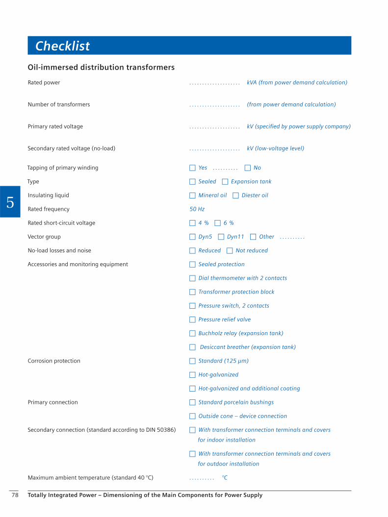
78
Checklist
Totally Integrated Power – Dimensioning of the Main Components for Power Supply
5
Oil-immersed distribution transformers
Rated power . . . . . . . . . . . . . . . . . . . . kVA (from power demand calculation)
Number of transformers . . . . . . . . . . . . . . . . . . . . (from power demand calculation)
Primary rated voltage . . . . . . . . . . . . . . . . . . . . kV (specified by power supply company)
Secondary rated voltage (no-load) . . . . . . . . . . . . . . . . . . . . kV (low-voltage level)
Tapping of primary winding c Yes . . . . . . . . . . c No
Type c Sealed c Expansion tank
Insulating liquid c Mineral oil c Diester oil
Rated frequency 50 Hz
Rated short-circuit voltage c 4 % c 6 %
Vector group c Dyn5 c Dyn11 c Other . . . . . . . . . .
No-load losses and noise c Reduced c Not reduced
Accessories and monitoring equipment c Sealed protection
c Dial thermometer with 2 contacts
c Transformer protection block
c Pressure switch, 2 contacts
c Pressure relief valve
c Buchholz relay (expansion tank)
c Desiccant breather (expansion tank)
Corrosion protection c Standard (125 µm)
c Hot-galvanized
c Hot-galvanized and additional coating
Primary connection c Standard porcelain bushings
c Outside cone – device connection
Secondary connection (standard according to DIN 50386) c With transformer connection terminals and covers
for indoor installation
c With transformer connection terminals and covers
for outdoor installation
Maximum ambient temperature (standard 40 °C) . . . . . . . . . . °C

79Totally Integrated Power – Dimensioning of the Main Components for Power Supply
5
5.5. Low-voltage Switchgear
When planning low-voltage switchgear, knowledge of the conditions at the location of use, the switching duty and the availability requirements are the basis for economic dimensioning.
As no major switching functions have to be considered in the planning of power distribution systems in commercial buildings and no major extensions are to be expected, a performance-optimized technology with high component density can be used. In these cases, mainly fuse-protected equipment in fixed-mounted design is used.
However, in a power distribution or motor control center for a production plant, replaceability and reliability of supply are the most important criteria in order to keep the
downtimes as short as possible. The use of withdrawable-unit design in not only circuit-breaker-protected, but also in fuse-protected systems is an important basis.
The prevention of personal injury and damage to equip-ment must, however, be the first priority in all cases. When selecting appropriate switchgear, it must be ensured that is a type-tested switchgear assembly (design verifica-tion according to IEC 61439-1 / -2 DIN VDE 0660-600-1 / -2) with extended testing of behavior in the event of an inter-nal arcing fault (IEC 61641, VDE 0660-500, Addendum 2). The selection of the switchgear and the protective devices must always be made under consideration of the regula-tions that have to be observed with regard to the require-ments for the entire supply system (full selectivity, partial selectivity) (Photo 55/1).
Photo 55/1: SIVACON S8 low-voltage switchgear
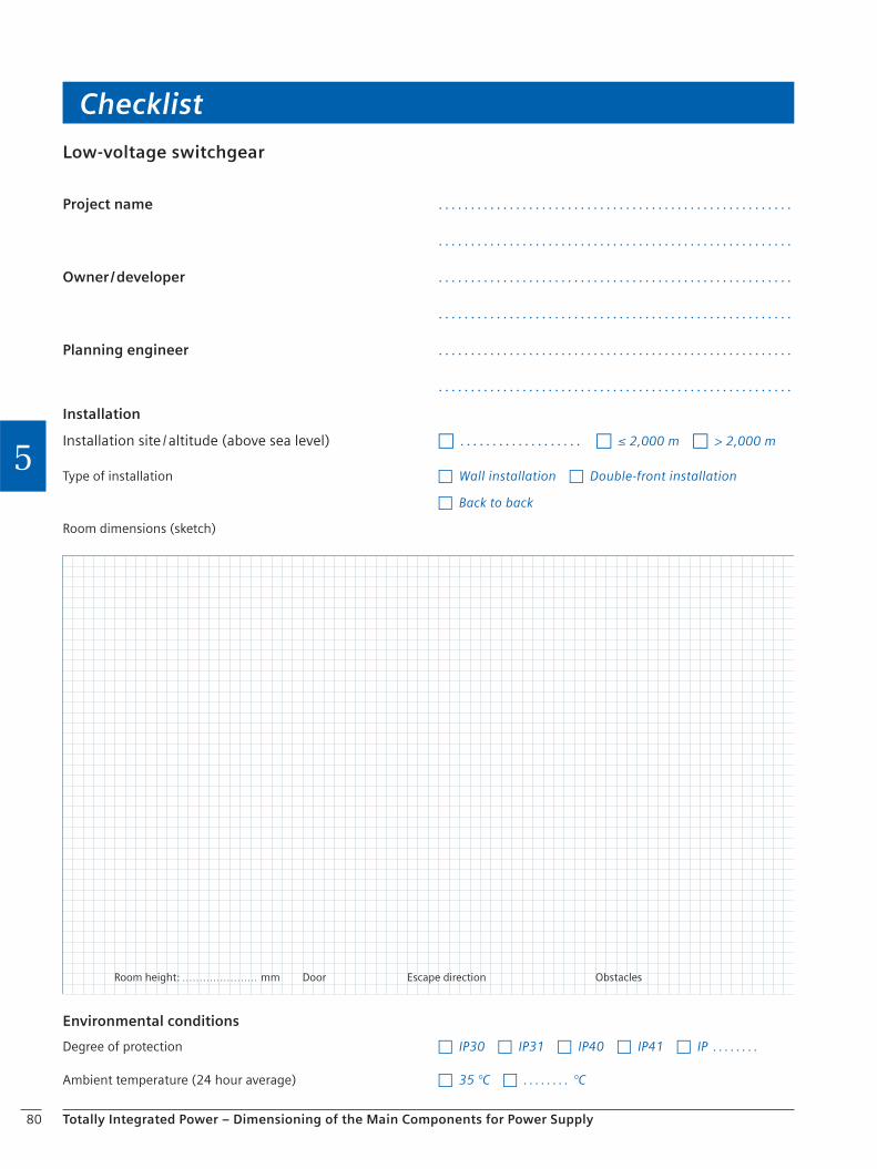
80
Checklist
Totally Integrated Power – Dimensioning of the Main Components for Power Supply
5
Environmental conditions
Degree of protection c IP30 c IP31 c IP40 c IP41 c IP . . . . . . . .
Ambient temperature (24 hour average) c 35 °C c . . . . . . . . °C
Low-voltage switchgear
Project name . . . . . . . . . . . . . . . . . . . . . . . . . . . . . . . . . . . . . . . . . . . . . . . . . . . . . . .
. . . . . . . . . . . . . . . . . . . . . . . . . . . . . . . . . . . . . . . . . . . . . . . . . . . . . . .
Owner / developer . . . . . . . . . . . . . . . . . . . . . . . . . . . . . . . . . . . . . . . . . . . . . . . . . . . . . . .
. . . . . . . . . . . . . . . . . . . . . . . . . . . . . . . . . . . . . . . . . . . . . . . . . . . . . . .
Planning engineer . . . . . . . . . . . . . . . . . . . . . . . . . . . . . . . . . . . . . . . . . . . . . . . . . . . . . . .
. . . . . . . . . . . . . . . . . . . . . . . . . . . . . . . . . . . . . . . . . . . . . . . . . . . . . . .
Installation
Installation site / altitude (above sea level) c . . . . . . . . . . . . . . . . . . . c ≤ 2,000 m c > 2,000 m
Type of installation c Wall installation c Double-front installation
c Back to back
Room dimensions (sketch)
Room height: . . . . . . . . . . . . . . . . . . . . . . mm Door Escape direction Obstacles

81
Checklist
Totally Integrated Power – Dimensioning of the Main Components for Power Supply
5
Supply system / feed-in data
Power supply system c TN-S c TN-S (EMC-friendly) c CGP
c TN-C c TN-C-S
c TT c IT
Number of transformers / power . . . . . . . . item / . . . . . . . . . kVA, ukr c 4 % c 6 %
Rated operating voltage Ue . . . . . . . . V
Rated frequency f c 50 Hz c . . . . . . . . . Hz
Rated feed-in current Ie . . . . . . . . A
Busbar system
Rated current of main busbar NPS / SPS section Ie . . . . . . . . A / . . . . . . . . A
Rated short-time withstand currentof main busbar NPS / SPS section Icw . . . . . . . . kA (1 s) / . . . . . . . . kA (1 s) /
PEN / N conductor cross section c 50 % c 100 %
Standards and regulations
Type-tested modules according to IEC 61439-1 / -2 c Yes
Protection against accidental arcing IEC / TR 61641(VDE 0660-500, Addendum 2) c Operator safety
c Operator and system safety
c Busbar insulation
Connection data
Connection of incoming / outgoing feeders > 630 A c Busbar trunking system c Cable
c SIVACON LDA / LDC
c SIVACON LXA / LXC
c Other
Connection direction to switchgear c Top c Bottom c Top / bottom
Mounting designs
Incoming feeders c Fixed mounting c Withdrawable-unit design
Couplings c Fixed mounting c Withdrawable-unit design
Outgoing feeders > 630 A c Fixed mounting c Withdrawable-unit design
Outgoing feeders ≤ 630 A c Fixed mounting c Withdrawable-unit design c Plug-in design
Type of outgoing feeders ≤ 630 A c Circuit-breaker protected c Fuse-protected

82 Totally Integrated Power – Dimensioning of the Main Components for Power Supply
5
5.5.1 Planning Notes for Low-voltage Switchgear
Installation – clearances and corridor widths
The minimum clearances between switchgear and obsta-cles specified by the manufacturer must be taken into account when installing low-voltage switchgear (Fig. 55/2). The minimum dimensions for operating and servicing corridors according to VDE 0100 Part 729 (IEC 60364-7-729 Draft) must be taken into account when planning the space requirements (Table 55/1, Fig. 55/3, Fig. 55/4).
Caution! If a lift truck is used to insert circuit-breakers or withdrawable units, the minimum corridor widths must be adapted to the lift truck!
Transportation units
Depending on the access routes available in the building, one or more panels can be combined into transportation units (TU). The max. length of a TU should not exceed 2,400 mm. The transportation unit length results from the sum of the panel widths per TU + 200 mm (230 mm), however at least 1,400 mm (1,430 mm).
The dimensions for the transportation unit heights result from the switchgear height plus 190 mm for the transport base.
The relevant depth of a transportation unit depends on the depth of the switchgear.
* Values in brackets = export packaging for shipping by sea
Weights
The panel weights as listed in Table 55/2 (Page 84) should be used for the transportation and dimensioning of build-ing structures such as cable basements and false floors.
Table 55/1: SIVACON S8 switchgear dimensions
Space requirements
Height: 2,000 mm and 2,200 mm (optionally with 100 mm or 200 mm base)
Width: For data required for the addition of panels please refer to the panel descriptions
Depth:
Busb
ar
po
siti
on
Rate
d cu
rren
t o
f th
e m
ain
b
usb
ar
Typ
e o
f in
stal
lati
on
Cab
le /
bu
sbar
en
try
600 mm Rear 4,000 A Single front Top & bottom
800 mm Rear 7,010 A Single front Top & bottom
1,000 mm Rear 4,000 A Double front Top & bottom
1,200 mm Rear 7,010 A Double front Top & bottom
500 mm Top 3,270 A Single front Bottom
800 mm Top 6,300 A Single front Bottom
1,200 mm Top 3,270 A Single front Top & bottom
Manufacturer e. g. Kaiser + Kraft
Dimensions of the lift truck
Height 2,000 mm
Width 680 mm
Depth 920 mm
Minimum corridor width about 1,500 mm
Fig. 55/2: Clearances to obstacles
Front
Front
Front
A: 100 mm from the rear side of the installationB: 100 mm from the side side panelsC: 200 mm from the rear panels with back to back installation
B
C
B
A
Depth Transportation unit depth
500 mm 1,050 mm (1,060 mm*)
600 mm 1,050 mm (1,060 mm*)
800 mm 1,050 mm (1,060 mm*)
1,000 mm 1,460 mm (1,490 mm*)
1,200 mm 1,660 mm (1,690 mm*)

83Totally Integrated Power – Dimensioning of the Main Components for Power Supply
5
Double-front installations
In the double-front installation, the panels are positioned in a row next to and behind one another. The main advan-tage of a double-front installation is the extremely eco-nomic design through the supply of the branch circuits on both operating panels from one main busbar system.
The "double-front unit" system structure is required for the assignment of certain modules.
A double-front unit (Fig. 55/5) consists of at least 2 and a maximum of 4 panels. The width of the double-front unit is determined by the widest panel (1) within the double-front unit. This panel can be placed on the front or rear side of the double-front unit. Up to three panels (2), (3), (4) can be placed on the opposite side. The sum of the panel widths (2) to (4) must be equal to the width of the widest panel (1). The panel combination within the double-front unit is possible for all technical installations with the following exceptions.
Exceptions
The following panels determine the width of the double-front unit and may only be combined with an empty panel.
Bus sectionalizer unit
5,000 A incoming / outgoing feeder
6,300 A incoming / outgoing feeder
Environmental conditions for switchgear
The climate and other external conditions (natural foreign substances, chemically active pollutants, small animals) may affect the switchgear to a varying extent. The effect depends on the heating / air-conditioning systems of the switchgear room. If higher concentrations are present, pollutant-reducing measures are required, for example:
Air-intake for operating room from a less contaminated point
Slightly pressurizing the operating room (e.g. by blowing uncontaminated air into the switchgear)
Switchgear room air conditioning (temperature reduction, relative humidity< 60 %, if necessary, use air filters)
Reduction of temperature rise (oversizing of switchgear or components such as busbars and distribution bars)
Power losses
The power losses listed in Table 55/3 (Page 84) are approxi-mate values for a panel with the main circuit of functional units to determine the power loss to be discharged from the switchgear room.
Fig. 55/3: Reduced corridor widths within the area of open doors
1) Minimum height of passage under covers or enclosures
600600
20
00
1)
700700700700
Fig. 55/4: Minimum corridor width according to VDE 0100 Part 729
Min. free passage500 mm 1)
Escapedirection
Min. corridor width700 or 600 mm
2)
1) With switchgear fronts facing each other, the space requirements only account for obstruction by open doors from one side (i.e. doors that don’t close in escape direction)2) Take door widths into account,
i.e. door can be opened at 90 ° minimumFull door opening angle = 125 ° (Sinus 55 °)
Fig. 55/5: Panel arrangement of double-front installations
Double-front units
Double-front installations – top viewDouble-front installations only with main busbar system at the rear
(1)
(3)(2) (4)
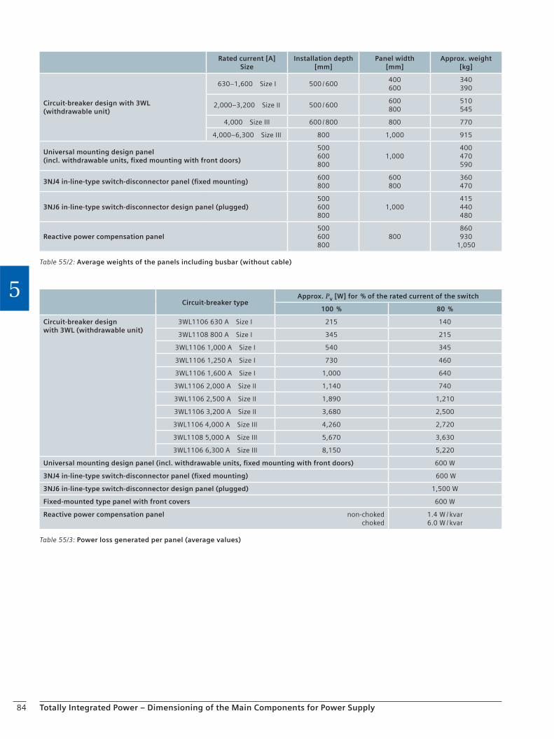
84 Totally Integrated Power – Dimensioning of the Main Components for Power Supply
5
Table 55/3: Power loss generated per panel (average values)
Circuit-breaker typeApprox. Pv [W] for % of the rated current of the switch
100 % 80 %
Circuit-breaker designwith 3WL (withdrawable unit)
3WL1106 630 A Size I 215 140
3WL1108 800 A Size I 345 215
3WL1106 1,000 A Size I 540 345
3WL1106 1,250 A Size I 730 460
3WL1106 1,600 A Size I 1,000 640
3WL1106 2,000 A Size II 1,140 740
3WL1106 2,500 A Size II 1,890 1,210
3WL1106 3,200 A Size II 3,680 2,500
3WL1106 4,000 A Size III 4,260 2,720
3WL1108 5,000 A Size III 5,670 3,630
3WL1106 6,300 A Size III 8,150 5,220
Universal mounting design panel (incl. withdrawable units, fixed mounting with front doors) 600 W
3NJ4 in-line-type switch-disconnector panel (fixed mounting) 600 W
3NJ6 in-line-type switch-disconnector design panel (plugged) 1,500 W
Fixed-mounted type panel with front covers 600 W
Reactive power compensation panel non-choked choked
1.4 W / kvar6.0 W / kvar
Table 55/2: Average weights of the panels including busbar (without cable)
Rated current [A]Size
Installation depth[mm]
Panel width[mm]
Approx. weight[kg]
Circuit-breaker design with 3WL(withdrawable unit)
630–1,600 Size I 500 / 600400600
340390
2,000–3,200 Size II 500 / 600600800
510545
4,000 Size III 600 / 800 800 770
4,000–6,300 Size III 800 1,000 915
Universal mounting design panel(incl. withdrawable units, fixed mounting with front doors)
500600800
1,000400470590
3NJ4 in-line-type switch-disconnector panel (fixed mounting)600 800
600800
360470
3NJ6 in-line-type switch-disconnector design panel (plugged)500600800
1,000415440480
Reactive power compensation panel500600800
800860930
1,050
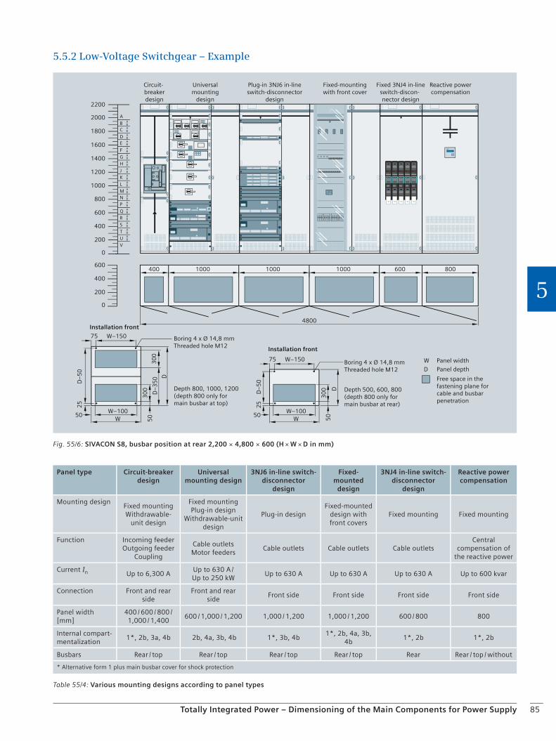
85Totally Integrated Power – Dimensioning of the Main Components for Power Supply
5
5.5.2 Low-Voltage Switchgear – Example
Table 55/4: Various mounting designs according to panel types
Panel type Circuit-breaker design
Universal mounting design
3NJ6 in-line switch-disconnector
design
Fixed-mounted
design
3NJ4 in-line switch-disconnector
design
Reactive power compensation
Mounting designFixed mountingWithdrawable-
unit design
Fixed mounting Plug-in design
Withdrawable-unit design
Plug-in designFixed-mounted
design with front covers
Fixed mounting Fixed mounting
Function Incoming feederOutgoing feeder
Coupling
Cable outletsMotor feeders
Cable outlets Cable outlets Cable outletsCentral
compensation of the reactive power
Current In Up to 6,300 A
Up to 630 A / Up to 250 kW
Up to 630 A Up to 630 A Up to 630 A Up to 600 kvar
Connection Front and rear side
Front and rear side
Front side Front side Front side Front side
Panel width [mm]
400 / 600 / 800 / 1,000 / 1,400
600 / 1,000 / 1,200 1,000 / 1,200 1,000 / 1,200 600 / 800 800
Internal compart-mentalization
1*, 2b, 3a, 4b 2b, 4a, 3b, 4b 1*, 3b, 4b1*, 2b, 4a, 3b,
4b1*, 2b 1*, 2b
Busbars Rear / top Rear / top Rear / top Rear / top Rear Rear / top / without
* Alternative form 1 plus main busbar cover for shock protection
Fig. 55/6: SIVACON S8, busbar position at rear 2,200 × 4,800 × 600 (H × W × D in mm)
Free space in the fastening plane for cable and busbar penetration
D
Panel width
Panel depth
Boring 4 x Ø 14,8 mmThreaded hole M12
Depth 800, 1000, 1200(depth 800 only for main busbar at top)
Installation front
Installation front
Circuit-breaker design
Universal mounting
design
Plug-in 3NJ6 in-line switch-disconnector
design
Fixed 3NJ4 in-line switch-discon-nector design
Reactive power compensation
Fixed-mounting with front cover
Boring 4 x Ø 14,8 mmThreaded hole M12
W
Depth 500, 600, 800(depth 800 only for main busbar at rear)
W–150
W–100
W–150
W–100
D
D–5
0D–5
0
D–3
50
D
W W
B
A
BA
C BA
D BA
E BA
F BA
G BA
H BA
J BA
K BA
L BA
M BA
N BA
P BA
Q BA
R BA
S BA
T BA
U BA
V
0
200
400
600
0
200
400
600
800
1000
1200
1400
1600
1800
2000
2200
4800
75
50
25
300
5030
0
75
50
25
300
50
400 1000 1000 1000 600 800
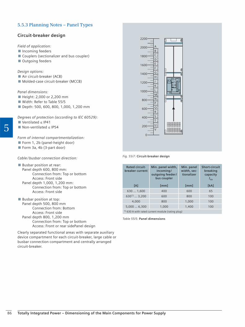
86 Totally Integrated Power – Dimensioning of the Main Components for Power Supply
5
5.5.3 Planning Notes – Panel Types
Circuit-breaker design
Field of application: Incoming feeders Couplers (sectionalizer and bus coupler) Outgoing feeders
Design options: Air circuit-breaker (ACB) Molded-case circuit-breaker (MCCB)
Panel dimensions: Height: 2,000 or 2,200 mm Width: Refer to Table 55/5 Depth: 500, 600, 800, 1,000, 1,200 mm
Degrees of protection (according to IEC 60529): Ventilated ≤ IP41 Non-ventilated ≤ IP54
Form of internal compartmentalization: Form 1, 2b (panel-height door) Form 3a, 4b (3-part door)
Cable / busbar connection direction:
Busbar position at rear: Panel depth 600, 800 mm: Connection from: Top or bottom Access: Front side Panel depth 1,000, 1,200 mm: Connection from: Top or bottom Access: Front side
Busbar position at top: Panel depth 500, 800 mm Connection from: Bottom Access: Front side Panel depth 800, 1,200 mm Connection from: Top or bottom Access: Front or rear sidePanel design
Clearly separated functional areas with separate auxiliary device compartment for each circuit-breaker, large cable or busbar connection compartment and centrally arranged circuit-breaker.
Rated circuit-breaker current
[A]
Min. panel width, incoming /
outgoing feeder / bus coupler
[mm]
Min. panel width, sec-tionalizer
[mm]
Short-circuit breaking capacity
Icu
[kA]
630 … 1,600 400 600 65
6301) … 3,200 600 800 100
4,000 800 1,000 100
5,000 … 6,300 1,000 1,400 1001) 630 A with rated current module (rating plug)
Table 55/5: Panel dimensions
B
A
BA
C BA
D BA
E BA
F BA
G BA
H BA
J BA
K BA
L BA
MBA
N BA
P BA
Q BA
R BA
S BA
T BA
U BA
V
0
200
400
600
800
1000
1200
1400
1600
1800
2000
2200
Fig. 55/7: Circuit-breaker design
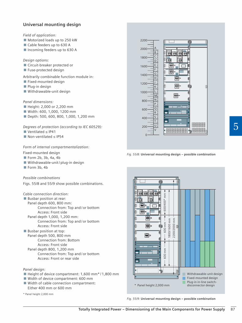
87Totally Integrated Power – Dimensioning of the Main Components for Power Supply
5
Universal mounting design
Field of application: Motorized loads up to 250 kW Cable feeders up to 630 A Incoming feeders up to 630 A
Design options: Circuit-breaker protected or Fuse-protected design
Arbitrarily combinable function module in: Fixed-mounted design Plug-in design Withdrawable-unit design
Panel dimensions: Height: 2,000 or 2,200 mm Width: 600, 1,000, 1200 mm Depth: 500, 600, 800, 1,000, 1,200 mm
Degrees of protection (according to IEC 60529): Ventilated ≤ IP41 Non-ventilated ≤ IP54
Form of internal compartmentalization:
Fixed-mounted design Form 2b, 3b, 4a, 4b Withdrawable-unit / plug-in design Form 3b, 4b
Possible combinations
Figs. 55/8 and 55/9 show possible combinations.
Cable connection direction: Busbar position at rear: Panel depth 600, 800 mm: Connection from: Top and / or bottom Access: Front side Panel depth 1,000, 1,200 mm: Connection from: Top and / or bottom Access: Front side Busbar position at top: Panel depth 500, 800 mm Connection from: Bottom Access: Front side Panel depth 800, 1,200 mm Connection from: Top and / or bottom Access: Front or rear side
Panel design: Height of device compartment: 1,600 mm* / 1,800 mm Width of device compartment: 600 mm Width of cable connection compartment: Either 400 mm or 600 mm
* Panel height 2,000 mm
B
A
BA
C BA
D BA
E BA
F BA
G BA
H BA
J BA
K BA
L BA
MBA
N BA
P BA
Q BA
R BA
S BA
T BA
U BA
V
0
200
400
600
800
1000
1200
1400
1600
1800
2000
2200
Fig. 55/8: Universal mounting design – possible combination
Fig. 55/9: Universal mounting design – possible combination
Withdrawable-unit design Fixed-mounted design Plug-in in-line switch- disconnector design * Panel height 2,000 mm
180
0/1
60
0 m
m
60
0 m
m6
00
mm
60
0/4
00
* m
m
22
00
/20
00
mm
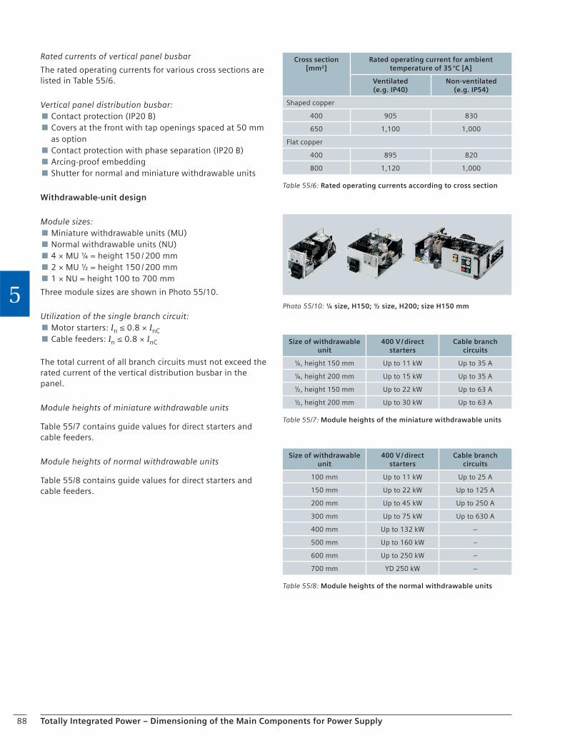
88 Totally Integrated Power – Dimensioning of the Main Components for Power Supply
5
Rated currents of vertical panel busbar
The rated operating currents for various cross sections are listed in Table 55/6.
Vertical panel distribution busbar: Contact protection (IP20 B) Covers at the front with tap openings spaced at 50 mm as option Contact protection with phase separation (IP20 B) Arcing-proof embedding Shutter for normal and miniature withdrawable units
Withdrawable-unit design
Module sizes: Miniature withdrawable units (MU) Normal withdrawable units (NU) 4 × MU ¼ = height 150 / 200 mm 2 × MU ½ = height 150 / 200 mm 1 × NU = height 100 to 700 mm
Three module sizes are shown in Photo 55/10.
Utilization of the single branch circuit: Motor starters: In ≤ 0.8 × InC Cable feeders: In ≤ 0.8 × InC
The total current of all branch circuits must not exceed the rated current of the vertical distribution busbar in the panel.
Module heights of miniature withdrawable units
Table 55/7 contains guide values for direct starters and cable feeders.
Module heights of normal withdrawable units
Table 55/8 contains guide values for direct starters and cable feeders.
Photo 55/10: ¼ size, H150; ½ size, H200; size H150 mm
Table 55/6: Rated operating currents according to cross section
Cross section [mm²]
Rated operating current for ambient temperature of 35 °C [A]
Ventilated(e.g. IP40)
Non-ventilated(e.g. IP54)
Shaped copper
400 905 830
650 1,100 1,000
Flat copper
400 895 820
800 1,120 1,000
Table 55/7: Module heights of the miniature withdrawable units
Size of withdrawable unit
400 V / direct starters
Cable branch circuits
¼, height 150 mm Up to 11 kW Up to 35 A
¼, height 200 mm Up to 15 kW Up to 35 A
½, height 150 mm Up to 22 kW Up to 63 A
½, height 200 mm Up to 30 kW Up to 63 A
Table 55/8: Module heights of the normal withdrawable units
Size of withdrawable unit
400 V / direct starters
Cable branch circuits
100 mm Up to 11 kW Up to 25 A
150 mm Up to 22 kW Up to 125 A
200 mm Up to 45 kW Up to 250 A
300 mm Up to 75 kW Up to 630 A
400 mm Up to 132 kW –
500 mm Up to 160 kW –
600 mm Up to 250 kW –
700 mm YD 250 kW –
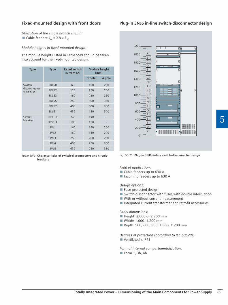
89Totally Integrated Power – Dimensioning of the Main Components for Power Supply
5
Fixed-mounted design with front doors
Utilization of the single branch circuit: Cable feeders: In ≤ 0.8 × InC
Module heights in fixed-mounted design:
The module heights listed in Table 55/9 should be taken into account for the fixed-mounted design.
Table 55/9: Characteristics of switch-disconnectors and circuit-breakers
Type Type Rated switch current [A]
Module height [mm]
3-pole 4-pole
Switch-disconnector with fuse
3KL50 63 150 250
3KL52 125 250 250
3KL53 160 250 250
3KL55 250 300 350
3KL57 400 300 350
3KL61 630 450 500
Circuit-breaker
3RV1.3 50 150 –
3RV1.4 100 150 –
3VL1 160 150 200
3VL2 160 150 200
3VL3 250 200 250
3VL4 400 250 300
3VL5 630 250 350
Plug-in 3NJ6 in-line switch-disconnector design
B
A
BA
C BA
D BA
E BA
F BA
G BA
H BA
J BA
K BA
L BA
MBA
N BA
P BA
Q BA
R BA
S BA
T BA
U BA
V
0
200
400
600
800
1000
1200
1400
1600
1800
2000
2200
Fig. 55/11: Plug-in 3NJ6 in-line switch-disconnector design
Field of application: Cable feeders up to 630 A Incoming feeders up to 630 A
Design options: Fuse-protected design Switch-disconnector with fuses with double interruption With or without current measurement Integrated current transformer and retrofit accessories
Panel dimensions: Height: 2,000 or 2,200 mm Width: 1,000, 1,200 mm Depth: 500, 600, 800, 1,000, 1,200 mm
Degrees of protection (according to IEC 60529): Ventilated ≤ IP41
Form of internal compartmentalization: Form 1, 3b, 4b
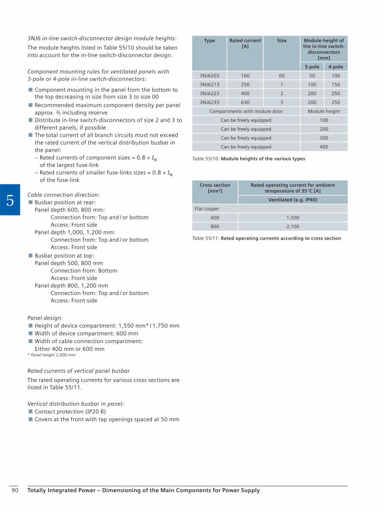
90 Totally Integrated Power – Dimensioning of the Main Components for Power Supply
5
3NJ6 in-line switch-disconnector design module heights:
The module heights listed in Table 55/10 should be taken into account for the in-line switch-disconnector design.
Component mounting rules for ventilated panels with 3-pole or 4-pole in-line switch-disconnectors:
Component mounting in the panel from the bottom to the top decreasing in size from size 3 to size 00
Recommended maximum component density per panel approx. ⅔ including reserve Distribute in-line switch-disconnectors of size 2 and 3 to different panels, if possible The total current of all branch circuits must not exceed the rated current of the vertical distribution busbar in the panel: – Rated currents of component sizes = 0.8 × IN
of the largest fuse-link – Rated currents of smaller fuse-links sizes = 0.8 × IN
of the fuse-link
Cable connection direction: Busbar position at rear: Panel depth 600, 800 mm: Connection from: Top and / or bottom Access: Front side Panel depth 1,000, 1,200 mm: Connection from: Top and / or bottom Access: Front side
Busbar position at top: Panel depth 500, 800 mm Connection from: Bottom Access: Front side Panel depth 800, 1,200 mm Connection from: Top and / or bottom Access: Front side
Panel design: Height of device compartment: 1,550 mm* / 1,750 mm Width of device compartment: 600 mm Width of cable connection compartment: Either 400 mm or 600 mm
* Panel height 2,000 mm
Rated currents of vertical panel busbar
The rated operating currents for various cross sections are listed in Table 55/11.
Vertical distribution busbar in panel: Contact protection (IP20 B) Covers at the front with tap openings spaced at 50 mm
Table 55/10: Module heights of the various types
Type Rated current [A]
Size Module height of the in-line switch-
disconnectors [mm]
3-pole 4-pole
3NJ6203 160 00 50 100
3NJ6213 250 1 100 150
3NJ6223 400 2 200 250
3NJ6233 630 3 200 250
Compartments with module door Module height
Can be freely equipped 100
Can be freely equipped 200
Can be freely equipped 300
Can be freely equipped 400
Table 55/11: Rated operating currents according to cross section
Cross section [mm²]
Rated operating current for ambient temperature of 35 °C [A]
Ventilated (e.g. IP40)
Flat copper
600 1,500
800 2,100

91Totally Integrated Power – Dimensioning of the Main Components for Power Supply
5
Fixed-mounting design with front cover
Field of application: Cable feeders up to 630 A Modular devices
Design options: Circuit-breaker-protected or fuse-protected design Single / multiple branch circuits
Panel dimensions: Height: 2,000 or 2,200 mm Width: 1,000, 1,200 mm Depth: 500, 600, 800, 1,000, 1,200 mm
Degrees of protection (according to IEC 60529):
Rack cover Ventilated ≤ IP31
Additional viewing or panel door Ventilated ≤ IP41 Non-ventilated ≤ IP54
Form of internal compartmentalization:
Single branch circuits Form 1, 2b, 3b, 4a, 4b
Multiple branch circuits Form 1, 2b
Utilization of the single branch circuit:Cable feeders: In ≤ 0.8 × InC
Cable connection direction: Busbar position at rear: Panel depth 600, 800 mm: Connection from: Top and / or bottom Access: Front side Panel depth 1,000, 1,200 mm: Connection from: Top and / or bottom Access: Front side Busbar position at top: Panel depth 500, 800 mm Connection from: Bottom Access: Front side Panel depth 800, 1,200 mm Connection from: Top and / or bottom Access: Front side
B
A
BA
C BA
D BA
E BA
F BA
G BA
H BA
J BA
K BA
L BA
MBA
N BA
P BA
Q BA
R BA
S BA
T BA
U BA
V
0
200
400
600
800
1000
1200
1400
1600
1800
2000
2200
Fig. 55/12: Fixed-mounting design with front cover
Table 55/12: Rated operating currents according to cross section
Cross section [mm²]
Rated operating current for ambient temperature of 35 °C [A]
Ventilated (e.g. IP40) Non-ventilated (e.g. IP54)
Shaped copper
400 905 830
650 1,100 1,000
Flat copper
400 895 820
800 1,120 1,000
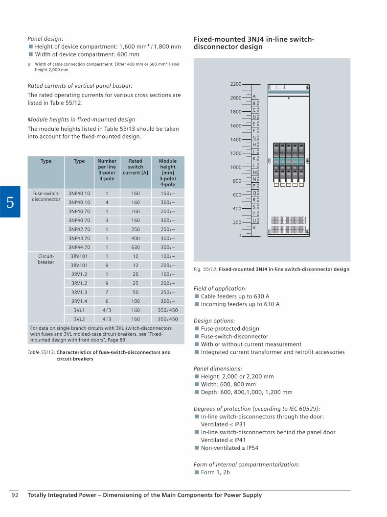
92 Totally Integrated Power – Dimensioning of the Main Components for Power Supply
5
Panel design: Height of device compartment: 1,600 mm* / 1,800 mm Width of device compartment: 600 mm
p Width of cable connection compartment: Either 400 mm or 600 mm* Panel height 2,000 mm
Rated currents of vertical panel busbar:
The rated operating currents for various cross sections are listed in Table 55/12.
Module heights in fixed-mounted design
The module heights listed in Table 55/13 should be taken into account for the fixed-mounted design.
Table 55/13: Characteristics of fuse-switch-disconnectors and circuit-breakers
Type Type Number per line3-pole / 4-pole
Rated switch
current [A]
Module height [mm]
3-pole / 4-pole
Fuse-switch-disconnector
3NP40 10 1 160 150 / –
3NP40 10 4 160 300 / –
3NP40 70 1 160 200 / –
3NP40 70 3 160 300 / –
3NP42 70 1 250 250 / –
3NP43 70 1 400 300 / –
3NP44 70 1 630 300 / –
Circuit-breaker
3RV101 1 12 100 / –
3RV101 9 12 200 / –
3RV1.2 1 25 100 / –
3RV1.2 9 25 200 / –
3RV1.3 7 50 250 / –
3RV1.4 6 100 300 / –
3VL1 4 / 3 160 350 / 450
3VL2 4 / 3 160 350 / 450
For data on single branch circuits with 3KL switch-disconnectors with fuses and 3VL molded-case circuit-breakers, see "Fixed-mounted design with front doors", Page 89
Fixed-mounted 3NJ4 in-line switch-disconnector design
B
A
BA
C BA
D BA
E BA
F BA
G BA
H BA
J BA
K BA
L BA
MBA
N BA
P BA
Q BA
R BA
S BA
T BA
U BA
V
0
200
400
600
800
1000
1200
1400
1600
1800
2000
2200
Fig. 55/13: Fixed-mounted 3NJ4 in-line switch-disconnector design
Field of application: Cable feeders up to 630 A Incoming feeders up to 630 A
Design options: Fuse-protected design Fuse-switch-disconnector With or without current measurement Integrated current transformer and retrofit accessories
Panel dimensions: Height: 2,000 or 2,200 mm Width: 600, 800 mm Depth: 600, 800,1,000, 1,200 mm
Degrees of protection (according to IEC 60529): In-line switch-disconnectors through the door: Ventilated ≤ IP31 In-line switch-disconnectors behind the panel door Ventilated ≤ IP41 Non-ventilated ≤ IP54
Form of internal compartmentalization: Form 1, 2b

93Totally Integrated Power – Dimensioning of the Main Components for Power Supply
5
Reactive power compensation
B
A
BA
C BA
D BA
E BA
F BA
G BA
H BA
J BA
K BA
L BA
MBA
N BA
P BA
Q BA
R BA
S BA
T BA
U BA
V
0
200
400
600
800
1000
1200
1400
1600
1800
2000
2200
Fig. 55/14: Reactive power compensation
Field of application: Closed-loop controlled reactive power compensation with connection to the main busbar or separate installation up to 600 kvar (Fig. 55/14).
Design options: Non-choked Choked: 5.67 %, 7 %, 14 % With / without AF suppression circuit With / without upstream switch-disconnector module as cut-off point between main and distribution busbar
Panel dimensions: Height: 2,000 or 2,200 mm Width: 800 mm Depth: 500, 600, 800, 1,000, 1,200 mm
Degrees of protection (according to IEC 60529): Ventilated ≤ IP41
Form of internal compartmentalization: Form 1, 2b
3NJ4 in-line switch-disconnector module heights
The module heights listed in Table 55/14 should be taken into account for the in-line switch-disconnector design.
Component mounting rules for panels with 3-pole 3NJ4 in-line switch-disconnectors:
Arrangement of the in-line switch-disconnectors in the panel: 3NJ4 in-line switch-disconnectors decreasing in size either from left to right or from right to left.
Permissible utilization of the branch circuits: The specified 3NJ4 rated currents apply for 3NJ4 in-line switch-disconnectors equipped with the largest possible LV HRC fuse-links. If smaller LV HRC fuse-links are used, the same proportionally smaller utilization is permitted.
Example: 3NJ414 in-line switch-disconnector in non-venti-lated panel equipped with 500 A LV HRC fuse-links, ambi-ent temperature ≤ 40 °C: Max. permissible continuous operating current = (370 A / 630 A) × 500 A = 290 ACable connection direction:
Busbar position at rear: Panel depth 600, 800 mm: Connection from: Top or bottom Access: Front side Panel depth 1,000, 1,200 mm: Connection from: Top or bottom Access: Front side
Panel design: Width of device compartment: 500 mm* / 700 mm
* Panel width 600 mm
Rated currents of vertical panel busbar
The rated operating currents for various cross sections are listed in Table 55/15.
Table 55/14: Module heights of the various types
Type Rated current [A]
Size Module height of the in-line switch-
disconnectors [mm]3-pole
3NJ410 160 00 50
3NJ412 250 1 100
3NJ413 400 2 100
3NJ414 630 3 100
Table 55/15: Rated operating currents according to cross section
Cross section [mm²]
Rated operating current for ambient temperature of 35 °C [A]
Ventilated (e.g. IP40) Non-ventilated (e.g. IP54)
Flat copper
6001) 1,560 1,430
1,0002) 2,180 1,790
1) Panel width 600 mm 2) Panel width 800 mm

94 Totally Integrated Power – Dimensioning of the Main Components for Power Supply
5
Active workWorking hours―――――― = ―――― = 92.6 kW
Power factor cos φ1 = 0.66 (for tan φ1 = 1.14)Power factor cos φ2 = 0.95 (desired)Conversion factor „F“ = 0.81 (from tan φ1 and cos φ2)Compensation power = mean power × factor „F“ = 92.6 kW × 0.81
Required compensation power: 75 kvar
16,600 kWh180 h
Reactive workActive work
tan φ1 = ―――――― = ――――― = 1.1419,000 kvarh16,600 kWh
Mean power consumption:
Reactive work Wb = 19,000 kvarh per monthActive work Ww = 16,660 kWh per month
Fig. 55/15: Sample calculation
Table 55/17: Back-up fuse and cable cross section
Reactive power per panel[kvar]
Back-up fuse[A]
Cable cross section[mm²]
50 100 35
100 250 120
150 355 2 × 70
200 500 2 × 120
250 630 2 × 150
300 2 × 355 2 × 185
350 2 × 400 4 × 95
400 2 × 500 4 × 120
450 2 × 500 4 × 120
500 2 × 630 4 × 150
600 2 × 630 4 × 185
Table 55/16: Installation options for reactive current compensation
Panel height
[mm]
Reactive power
per panel
[kvar]
Number of steps
[kvar]
Choking possible
Installation option
Busbar position
at the rear
Busbar position
at the top
< 2,200
50 2 × 25 Yes Yes Yes
100 4 × 25 Yes Yes Yes
150 6 × 25 Yes Yes Yes
200 4 × 50 Yes Yes Yes
250 5 × 50 Yes Yes Yes
300 6 × 50 Yes Yes Yes
350 7 × 50 Yes Yes Yes
400 8 × 50 Yes Yes Yes
2,200
400 8 × 50 Yes Yes Yes
450 9 × 50 Yes 1) Yes 1) No
500 10 × 50 Yes 1) Yes 1) No
600 12 × 50 No No No
1) Can only be implemented with IP30 / IP31 degree of protection
Selection table for direct connection to main busbar
Table 55/16
Cable connection direction:
Busbar position at rear Panel depth 600, 800 mm: Connection from: Bottom Access: Front side Panel depth 1,000, 1,200 mm: Connection from: Bottom Access: Front side
Busbar position at top Panel depth 500, 800 mm Connection from: Bottom Access: Front side Panel depth 800, 1,200 mm Connection from: Bottom Access: Front side
Panel design: Height of device compartment: 1,600 mm* / 1,800 mm Width of device compartment: 800 mm
* Panel height 2,000 mm
Selection table for back-up fuse and connecting cable for separate installation, see Table 55/17.
Calculation and determination of required capacitor power:
1. The electricity bill of the power supply company shows the consumption of active work in kWh and reactive work in kVArh; the company demands a cos φ of 0.9 ... 0.95; in order to cut costs, reactive work shall be compensated to a value approximating cos φ = 1.
Reactive workActive work
tan φ1 = ―――――― = ――kvarhkWh
Determination of tan φ1:
2. Refer to Table 55/18 for the conversion factor "F" and multiply it with the mean power consumption Pm. With tan φ1, cos φ1 shows the power factor prior to compensation, cos φ2 shows in factor "F" the desired power factor for compensation. The required compensation power is specified in kVAr.
Determination of the required compensation power:
The required compensation power can be determined with the values of Table 55/18.
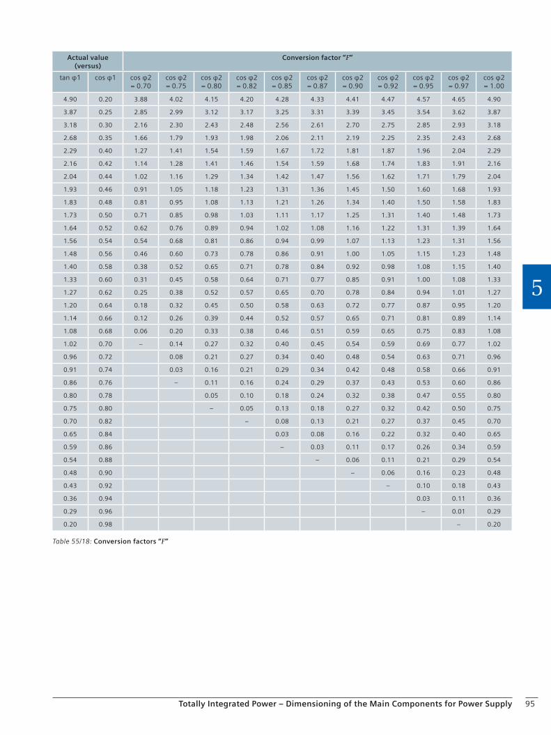
95Totally Integrated Power – Dimensioning of the Main Components for Power Supply
5
Table 55/18: Conversion factors “F”
Actual value (versus)
Conversion factor “F”
tan φ1 cos φ1 cos φ2= 0.70
cos φ2= 0.75
cos φ2= 0.80
cos φ2= 0.82
cos φ2= 0.85
cos φ2= 0.87
cos φ2= 0.90
cos φ2= 0.92
cos φ2= 0.95
cos φ2= 0.97
cos φ2= 1.00
4.90 0.20 3.88 4.02 4.15 4.20 4.28 4.33 4.41 4.47 4.57 4.65 4.90
3.87 0.25 2.85 2.99 3.12 3.17 3.25 3.31 3.39 3.45 3.54 3.62 3.87
3.18 0.30 2.16 2.30 2.43 2.48 2.56 2.61 2.70 2.75 2.85 2.93 3.18
2.68 0.35 1.66 1.79 1.93 1.98 2.06 2.11 2.19 2.25 2.35 2.43 2.68
2.29 0.40 1.27 1.41 1.54 1.59 1.67 1.72 1.81 1.87 1.96 2.04 2.29
2.16 0.42 1.14 1.28 1.41 1.46 1.54 1.59 1.68 1.74 1.83 1.91 2.16
2.04 0.44 1.02 1.16 1.29 1.34 1.42 1.47 1.56 1.62 1.71 1.79 2.04
1.93 0.46 0.91 1.05 1.18 1.23 1.31 1.36 1.45 1.50 1.60 1.68 1.93
1.83 0.48 0.81 0.95 1.08 1.13 1.21 1.26 1.34 1.40 1.50 1.58 1.83
1.73 0.50 0.71 0.85 0.98 1.03 1.11 1.17 1.25 1.31 1.40 1.48 1.73
1.64 0.52 0.62 0.76 0.89 0.94 1.02 1.08 1.16 1.22 1.31 1.39 1.64
1.56 0.54 0.54 0.68 0.81 0.86 0.94 0.99 1.07 1.13 1.23 1.31 1.56
1.48 0.56 0.46 0.60 0.73 0.78 0.86 0.91 1.00 1.05 1.15 1.23 1.48
1.40 0.58 0.38 0.52 0.65 0.71 0.78 0.84 0.92 0.98 1.08 1.15 1.40
1.33 0.60 0.31 0.45 0.58 0.64 0.71 0.77 0.85 0.91 1.00 1.08 1.33
1.27 0.62 0.25 0.38 0.52 0.57 0.65 0.70 0.78 0.84 0.94 1.01 1.27
1.20 0.64 0.18 0.32 0.45 0.50 0.58 0.63 0.72 0.77 0.87 0.95 1.20
1.14 0.66 0.12 0.26 0.39 0.44 0.52 0.57 0.65 0.71 0.81 0.89 1.14
1.08 0.68 0.06 0.20 0.33 0.38 0.46 0.51 0.59 0.65 0.75 0.83 1.08
1.02 0.70 – 0.14 0.27 0.32 0.40 0.45 0.54 0.59 0.69 0.77 1.02
0.96 0.72 0.08 0.21 0.27 0.34 0.40 0.48 0.54 0.63 0.71 0.96
0.91 0.74 0.03 0.16 0.21 0.29 0.34 0.42 0.48 0.58 0.66 0.91
0.86 0.76 – 0.11 0.16 0.24 0.29 0.37 0.43 0.53 0.60 0.86
0.80 0.78 0.05 0.10 0.18 0.24 0.32 0.38 0.47 0.55 0.80
0.75 0.80 – 0.05 0.13 0.18 0.27 0.32 0.42 0.50 0.75
0.70 0.82 – 0.08 0.13 0.21 0.27 0.37 0.45 0.70
0.65 0.84 0.03 0.08 0.16 0.22 0.32 0.40 0.65
0.59 0.86 – 0.03 0.11 0.17 0.26 0.34 0.59
0.54 0.88 – 0.06 0.11 0.21 0.29 0.54
0.48 0.90 – 0.06 0.16 0.23 0.48
0.43 0.92 – 0.10 0.18 0.43
0.36 0.94 0.03 0.11 0.36
0.29 0.96 – 0.01 0.29
0.20 0.98 – 0.20
96 Totally Integrated Power – Dimensioning of the Main Components for Power Supply
5
5.6 Busbar Trunking Systems
5.6.1 General
When a planning concept for power supply is developed, it is not only imperative to observe standards and regula-tions, it is also important to discuss and clarify economic and technical interrelations. The rating and selection of electric equipment, such as distribution boards and trans-formers, must be performed in such a way that an opti-mum result for the power system as a whole is kept in mind rather than focusing on individual components.
All components must be sufficiently rated to withstand normal operating conditions as well as fault conditions. Further important aspects to be considered for the creation of an energy concept are:
Type, use and shape of the building (e.g. high-rise building, low-rise building, multi-storey building)
Load centers and possible power transmission routes and locations for transformers and main distribution boards
Building-related connection values according to specific area loads that correspond to the building’s type of use
Statutory provisions and conditions imposed by building authorities
Requirements of the power distribution network operator
The result will never be a single solution. Several options must be assessed in terms of their technical and economic impacts. The following requirements are the main points of interest:
Easy and transparent planning
Long service life
High availability
Low fire load
Flexible adaptation to changes in the building
Most applications suggest the use of suitable busbar trunking systems to meet these requirements. For this reason, engineering companies increasingly prefer busbar trunking to cable installation for power transmission and distribution. Siemens offers busbar trunking systems ranging from 25 A to 6,300 A.
5.6.2 Planning Notes
Considering the complexity of modern building projects, transparency and flexibility of power distribution are indispensable requirements. In industry, the focus is on continuous supply of energy as an essential prerequisite for multi-shift production. Busbar trunking systems meet all these requirements on efficient power distribution by being easily planned, quickly installed and providing a high degree of flexibility and safety. The advantages of busbar trunking systems are:
Straightforward network configuration
Low space requirements
Easy retrofitting in case of changes of locations and consumer loads
High short-circuit strength and low fire load
Increased planning security
Power transmission
Power from the transformer to the low-voltage switchgear is transmitted by suitable components in the busbar trunk-ing system. These components are installed between trans-former and main distribution board, then branching to sub-distribution systems.
Trunking units without tap-off points are used for power transmission. These are available in standard lengths. Besides the standard lengths, the customer can also choose a specific length from various length ranges to suit individual constructive requirements.
Power distribution
Power distribution is the main area of application for busbar trunking systems. This means that electricity can-not just be tapped from a permanently fixed point as with a cable installation. Tapping points can be varied and changed as desired within the entire power distribution system.
In order to tap electricity, you just have plug a tap-off unit on the busbar at the tap-off point. This way a variable distribution system is created for linear and / or area-wide, distributed power supply. Tap-off points are provided on either or just one side on the straight trunking units.
For each busbar trunking system, a wide range of tap-off units is available for the connection of equipment and electricity supply.
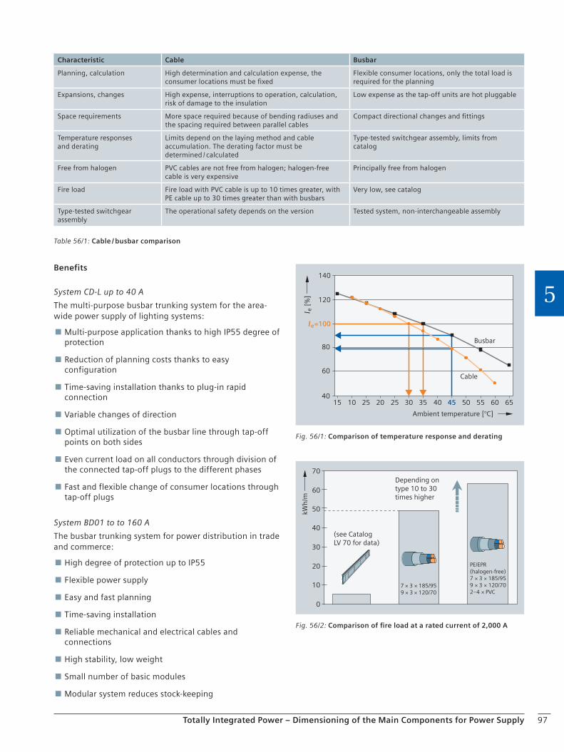
97Totally Integrated Power – Dimensioning of the Main Components for Power Supply
5
Table 56/1: Cable / busbar comparison
Characteristic Cable Busbar
Planning, calculation High determination and calculation expense, the consumer locations must be fixed
Flexible consumer locations, only the total load is required for the planning
Expansions, changes High expense, interruptions to operation, calculation, risk of damage to the insulation
Low expense as the tap-off units are hot pluggable
Space requirements More space required because of bending radiuses and the spacing required between parallel cables
Compact directional changes and fittings
Temperature responses and derating
Limits depend on the laying method and cable accumulation. The derating factor must be determined / calculated
Type-tested switchgear assembly, limits from catalog
Free from halogen PVC cables are not free from halogen; halogen-free cable is very expensive
Principally free from halogen
Fire load Fire load with PVC cable is up to 10 times greater, with PE cable up to 30 times greater than with busbars
Very low, see catalog
Type-tested switchgear assembly
The operational safety depends on the version Tested system, non-interchangeable assembly
Benefits
System CD-L up to 40 A
The multi-purpose busbar trunking system for the area-wide power supply of lighting systems:
Multi-purpose application thanks to high IP55 degree of protection
Reduction of planning costs thanks to easy configuration
Time-saving installation thanks to plug-in rapid connection
Variable changes of direction
Optimal utilization of the busbar line through tap-off points on both sides
Even current load on all conductors through division of the connected tap-off plugs to the different phases
Fast and flexible change of consumer locations through tap-off plugs
System BD01 to to 160 A
The busbar trunking system for power distribution in trade and commerce:
High degree of protection up to IP55
Flexible power supply
Easy and fast planning
Time-saving installation
Reliable mechanical and electrical cables and connections
High stability, low weight
Small number of basic modules
Modular system reduces stock-keeping
Fig. 56/1: Comparison of temperature response and derating
Ambient temperature [°C]
Busbar
Cable
120
80
60
4010 20 30 40 50 60 65554535252515
I =100
I [
%]
140
e
e
Fig. 56/2: Comparison of fire load at a rated current of 2,000 A
Depending on type 10 to 30times higher
(see Catalog LV 70 for data)
7 × 3 × 185/959 × 3 × 120/70
PE/EPR (halogen-free)7 × 3 × 185/959 × 3 × 120/702–4 × PVC
kWh
/m
10
20
30
50
40
60
70
0
98 Totally Integrated Power – Dimensioning of the Main Components for Power Supply
5
Variable changes of direction
Multi-purpose tap-off units
Forced opening and closing of the tap-off point
System BD2 up to 1,250 A
The busbar trunking system for power distribution in the aggressive industrial environment:
High degree of protection up to IP55
Easy and fast planning
Time-saving and economic installation
Safe and reliable operation
Flexible, modular system providing simple solutions for every application
Advance power distribution planning without precise knowledge of device locations
Ready to use in no time thanks to fast and easy installation
Innovative construction: expansion units to compensate for expansion are eliminated.
Tap-off units and tap-off points can be coded at the factory
Uniformly sealable
System LD up to 5,000 A
The perfect busbar trunking system for power distribution in industrial environments:
High IP54 degree of protection
Easy and rapid installation
Safe and reliable operation
Space-saving, compact design, up to 5,000 A in one casing
Load feeders up to 1,250 A
Type-tested connection to distribution board and transformers
System LX up to 6,300 A
The busbar trunking system for power transmission and distribution in buildings:
High degree of protection up to IP55
Easy and rapid installation
Safe and reliable operation
Load feeders up to 1,250 A
Type-tested connection to distribution board and transformers
System LR
The busbar trunking system for power transmission in extreme environmental requirements (IP68). Detailed information on this system is available in your local Siemens AG office.
Communication-capable busbar trunking system
Communication-capable functional extensions to be com-bined with known tap-off units:
For use with the systems BD01, BD2, LD and LX
Applications: – Large-scale lighting control – Remote switching and signaling in industrial environments – Consumption metering of distributed load feeders
Interfacing to KNX / EIB, AS-Interface and PROFIBUS bus systems
Easy contacting of the bus line with insulation displacement method
Easy and fast planning
Flexible for extension and modification
Modular system
Retrofitting to existing installations possible
Further information
Busbar trunking system selection guide (MobileSpice)
You can order busbar trunking systems up to 1,250 A with the selection guide.
The following configurators are available:
SIVACON 8PS system CD-L, 25 … 40 A
SIVACON 8PS system BD01, 40 … 160 A
SIVACON 8PS system BD2, 160 … 1,250 A
This selection guide is available via the A&D Mall and contained on DVD in Catalog CA 01. This DVD is available free-of-charge from your Siemens sales office.
Manual
Planning with SIVACON 8PS – Busbar Trunking Systems up to 6,300 A
German: Order no. A5E 01541017-01
English: Order no. A5E 01541117-01
Brochure
Busbar Trunking Systems for Safe and Flexible Power Distribution up to 6,300 A
German: Order no. E20001-A220-P309-V2
English: Order no. E20001-A220-P309-V2-7600
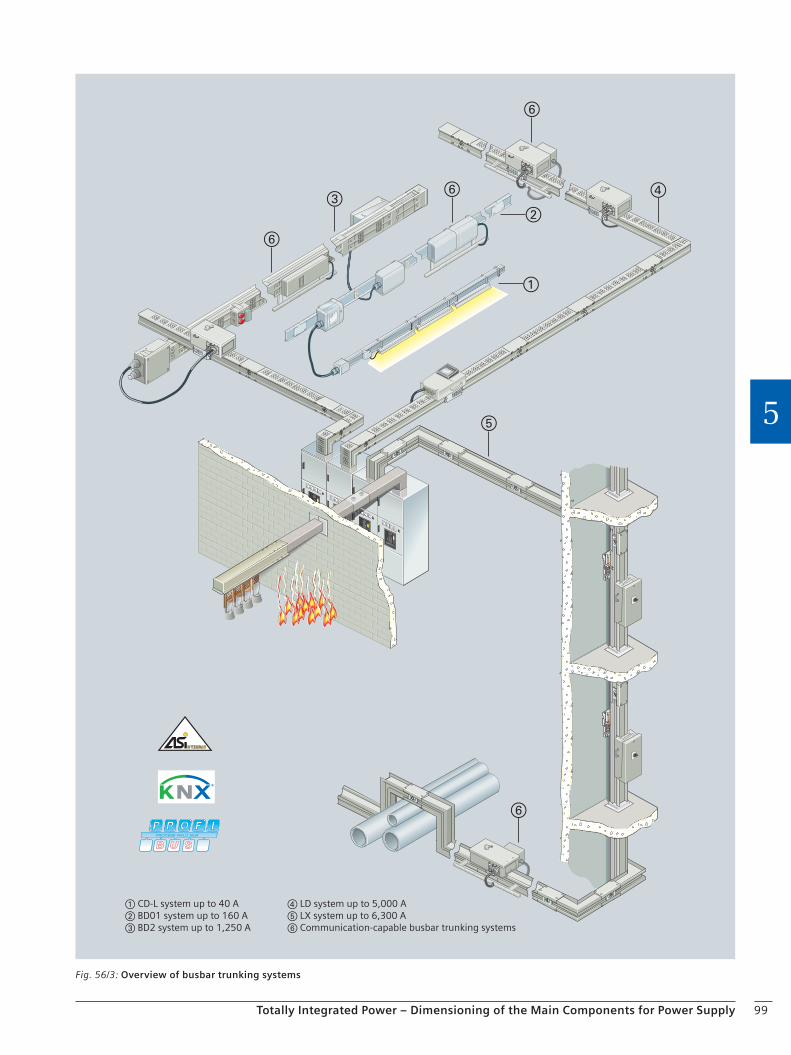
99Totally Integrated Power – Dimensioning of the Main Components for Power Supply
5
CD-L system up to 40 A BD01 system up to 160 A BD2 system up to 1,250 A
LD system up to 5,000 A LX system up to 6,300 A Communication-capable busbar trunking systems
Fig. 56/3: Overview of busbar trunking systems
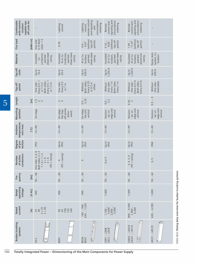
100 Totally Integrated Power – Dimensioning of the Main Components for Power Supply
5
Tab
le 5
6/2
: Ra
tin
g d
ata
ove
rvie
w f
or
bu
sba
r tr
un
kin
g s
yste
ms
Bu
sbar
tru
nki
ng
sy
ste
ms
Rat
ed
cu
rre
nt
[A]
Rat
ed
o
pe
rati
ng
vo
ltag
e
[V A
C]
Fre
-q
ue
ncy
[Hz]
Nu
mb
er
of
acti
ve
con
du
cto
rs
De
gre
e o
f p
ro-
tect
ion
Am
bie
nt
tem
pe
ratu
re,
min
/ max
[ °C
]
Mo
un
tin
g
po
siti
on
Len
gth
[m]
Tap
-off
p
oin
ts
Tap
-off
u
nit
sM
ate
rial
Fire
load
[kW
h / m
]
Co
mb
inab
le
wit
h c
om
mu
-n
icat
ion
- ca
pab
le t
ap-
off
un
its
for
CD
-L2
54
02
× 2
52
× 4
0
40
05
0 …
60
On
e si
de:
2, 4
, 6Bo
th s
ides
: 2 ×
21
× 4
+ 1
× 2
2 ×
42
× 6
(PE
= c
asin
g)
IP5
5−
5 / +
40
On
ed
ge
1.5 2 3
On
e si
de:
Ever
y 0
.5,
1
or
1.5
mBo
th s
ides
:Ev
ery
0.5
, 1
o
r 1
.5 m
Up
to
16
AIn
sula
ted
Cu
co
nd
uct
or,
p
ain
ted
shee
t-st
eel
casi
ng
On
e si
de:
0
.75
Bot
h
sid
es:
1.5
–
BD0
14
06
31
00
12
51
60
40
05
0 …
60
4(P
E =
cas
ing
)U
p t
o IP
55
−5
/ +4
0O
n e
dg
e,
flat
(ta
p-
off
po
ints
d
ow
n-
war
d)
2 3O
ne
sid
e:
Ever
y 0
.5
or
1 m
Up
to
63
AIn
sula
ted
Al o
r C
u
con
du
cto
r,
pai
nte
d sh
eet-
stee
l ca
sin
g
0.7
6Li
gh
tin
g co
ntr
ol
BD2
ABD
2C
16
0 …
40
06
30
… 1
,25
06
90
50
… 6
05
Up
to
IP5
5−
5 / +
40
On
ed
ge,
fl
at a
nd
vert
ical
0.5
…
3.2
5W
ith
ou
tBo
th s
ides
: Ev
ery
0.2
5
or
0.5
m
off
set
Up
to
63
0 A
Al o
r C
u
bu
sbar
s,
pai
nte
d sh
eet-
stee
l ca
sin
g
0.6
…
0.6
7
(wit
ho
ut
tap
-off
p
oin
ts)
Lig
hti
ng
con
tro
l,re
mot
e co
ntr
ol
and
sig
nal
ing
and
con
sum
ptio
n
met
erin
g
LDA
1 …
LD
A8
LDC
2 …
LD
C8
1,1
00
…
4,0
00
2,0
00
…
5,0
00
1,0
00
50
… 6
04
or
5U
p t
o IP
54
−5
/ +4
0H
ori
zon
-ta
l, o
n
edg
e an
d ve
rtic
al
0.5
…
3.2
Wit
ho
ut
On
e si
de:
Ev
ery
1 m
Bo
th s
ides
: Ev
ery
1 m
Up
to
1,2
50
AIn
sula
ted
Al o
r C
u
bu
sbar
s,
pai
nte
d sh
eet-
stee
l ca
sin
g
4.1
6 …
8
.83
(w
ith
ou
t ta
p-o
ff
po
ints
)
Rem
ote
con
tro
l an
d si
gn
alin
g a
nd
con
sum
ptio
n
met
erin
g
LXA
01
… L
XA
10
LXC
01
… L
XC
10
80
0 …
4,5
00
1,0
00
…
6,3
00
1,0
00
50
… 6
03
, 4, 5
, 6(P
E =
cas
ing
)U
p t
o IP
55
−5
/ +4
0H
ori
zon
-ta
l, o
n
edg
e an
d ve
rtic
al
0.3
5 …
3
Wit
ho
ut
On
e si
de:
Ev
ery
0,5
m
Both
sid
es:
Ever
y 0
.5 m
Up
to
1,2
50
AIn
sula
ted
Al o
r C
u
bu
sbar
s,
pai
nte
d al
um
inu
m
casi
ng
1.9
5 …
1
1.0
7
(wit
ho
ut
tap
-off
p
oin
ts)
Rem
ote
con
tro
l an
d si
gn
alin
g a
nd
con
sum
ptio
n
met
erin
g
LRC
01
… L
RC2
96
30
… 6
,30
01
,00
05
0 …
60
4, 5
IP6
8−
5 / +
40
Ho
rizo
n-
tal,
on
ed
ge
and
vert
ical
0.5
… 3
Wit
ho
ut
On
e si
de:
Se
lect
able
Up
to
63
0 A
Epox
y re
sin
sy
stem
, C
u
bu
sbar
s
––
101
Checklist
Totally Integrated Power – Dimensioning of the Main Components for Power Supply
5
Busbar trunking systems
Project name . . . . . . . . . . . . . . . . . . . . . . . . . . . . . . . . . . . . . . . . . . . . . . . . . . . . . . .
. . . . . . . . . . . . . . . . . . . . . . . . . . . . . . . . . . . . . . . . . . . . . . . . . . . . . . .
Owner / developer . . . . . . . . . . . . . . . . . . . . . . . . . . . . . . . . . . . . . . . . . . . . . . . . . . . . . . .
. . . . . . . . . . . . . . . . . . . . . . . . . . . . . . . . . . . . . . . . . . . . . . . . . . . . . . .
Planning engineer . . . . . . . . . . . . . . . . . . . . . . . . . . . . . . . . . . . . . . . . . . . . . . . . . . . . . . .
Rated operating voltage . . . . . . . . . . . . . . . . . . . . . . . . . . . . . . . . . . . . . . . . . . . . . . . . . . . . . . .
Rated current
(depending on degree of protection and laying method) . . . . . . . . . . . . . . . . . . . . . . . . . . . . . . . . . . . . . . . . . . . . . . . . . . . . . . .
Ambient temperature . . . . . . . . . . . . . . . . . . . . . . . . . . . . . . . . . . . . . . . . . . . . . . . . . . . . . . .
Degree of protection . . . . . . . . . . . . . . . . . . . . . . . . . . . . . . . . . . . . . . . . . . . . . . . . . . . . . . .
Power supply system c TN-S c TN-S (EMC-friendly)
c TN-C c TN-C-S c TT c IT
Type-tested connection to LVMD c Yes
Conductor configuration c L1, L2, L3 c N c 2 N
c PE c . . . . . . . . PE c PE = casing
Maximum voltage drop
(from supply to busbar to the final load feeder) . . . . . . . . . . . . . . . . . . . . . . . . . . . . . . . . . . . . . . . . . . . . . . . . . . . . . . .
Number of fire barriers (wall lead-through bushings) . . . . . . . . . . . . . . . . . . . . . . . . . . . . . . . . . . . . . . . . . . . . . . . . . . . . . . .
Proportion of busbars with fire barriers (in m) . . . . . . . . . . . . . . . . . . . . . . . . . . . . . . . . . . . . . . . . . . . . . . . . . . . . . . .
Fastening / routing of busbar . . . . . . . . . . . . . . . . . . . . . . . . . . . . . . . . . . . . . . . . . . . . . . . . . . . . . . .
Busbar layout drawing (incl. lengths and loads) . . . . . . . . . . . . . . . . . . . . . . . . . . . . . . . . . . . . . . . . . . . . . . . . . . . . . . .
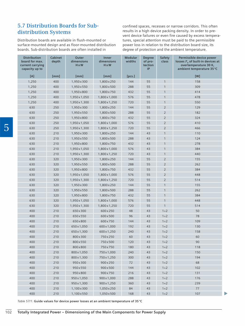
102 Totally Integrated Power – Dimensioning of the Main Components for Power Supply
5
5.7 Distribution Boards for Sub-distribution SystemsDistribution boards are available in flush-mounted or surface-mounted design and as floor-mounted distribution boards. Sub-distribution boards are often installed in
confined spaces, recesses or narrow corridors. This often results in a high device packing density. In order to pre-vent device failures or even fire caused by excess tempera-tures, special attention must be paid to the permissible power loss in relation to the distribution board size, its degree of protection and the ambient temperature.
Table 57/1: Guide values for device power losses at an ambient temperature of 35 °C
Distribution board for max.
current carrying capacity up to
[A]
Cabinet depth
[mm]
Outer dimensions
H x W
[mm]
Inner dimensions
H x W
[mm]
Modular widths
[pcs.]
Degree of pro-tection
IP
Safety class
Permissible device power losses Pv of built-in devices at
overtemperature 30 K, ambient temperature 35 °C
[W]
1,250 400 1,950 x 300 1,800 x 250 144 55 1 158
1,250 400 1,950 x 550 1,800 x 500 288 55 1 309
1,250 400 1,950 x 800 1,800 x 750 432 55 1 414
1,250 400 1,950 x 1,050 1,800 x 1,000 576 55 1 478
1,250 400 1,950 x 1,300 1,800 x 1,250 720 55 1 550
630 250 1,950 x 300 1,800 x 250 144 55 2 129
630 250 1,950 x 550 1,800 x 500 288 55 2 182
630 250 1,950 x 800 1,800 x 750 432 55 2 324
630 250 1,950 x 1,050 1,800 x 1,000 576 55 2 410
630 250 1,950 x 1,300 1,800 x 1,250 720 55 2 466
630 210 1,950 x 300 1,800 x 250 144 43 1 110
630 210 1,950 x 550 1,800 x 500 288 43 1 124
630 210 1,950 x 800 1,800 x 750 432 43 1 278
630 210 1,950 x 1,050 1,800 x 1,000 576 43 1 384
630 210 1,950 x 1,300 1,800 x 1,250 720 43 1 440
630 320 1,950 x 300 1,800 x 250 144 55 2 155
630 320 1,950 x 550 1,800 x 500 288 55 2 262
630 320 1,950 x 800 1,800 x 750 432 55 2 384
630 320 1,950 x 1,050 1,800 x 1,000 576 55 2 448
630 320 1,950 x 1,300 1,800 x 1,250 720 55 2 514
630 320 1,950 x 300 1,800 x 250 144 55 1 155
630 320 1,950 x 550 1,800 x 500 288 55 1 262
630 320 1,950 x 800 1,800 x 750 432 55 1 384
630 320 1,950 x 1,050 1,800 x 1,000 576 55 1 448
630 320 1,950 x 1,300 1,800 x 1,250 720 55 1 514
400 210 650 x 300 600 x 250 48 43 1+2 50
400 210 650 x 550 600 x 500 96 43 1+2 78
400 210 650 x 800 600 x 750 144 43 1+2 109
400 210 650 x 1,050 600 x 1,000 192 43 1+2 130
400 210 650 x 1,300 600 x 1,250 240 43 1+2 158
400 210 800 x 300 750 x 250 60 43 1+2 60
400 210 800 x 550 750 x 500 120 43 1+2 90
400 210 800 x 800 750 x 750 180 43 1+2 118
400 210 800 x 1,050 750 x 1,000 240 43 1+2 150
400 210 800 x 1,300 750 x 1,250 300 43 1+2 194
400 210 950 x 300 900 x 250 72 43 1+2 68
400 210 950 x 550 900 x 500 144 43 1+2 102
400 210 950 x 800 900 x 750 216 43 1+2 131
400 210 950 x 1,050 900 x 1,000 288 43 1+2 176
400 210 950 x 1,300 900 x 1,250 360 43 1+2 239
400 210 1,100 x 300 1,050 x 250 84 43 1+2 77
400 210 1,100 x 550 1,050 x 500 168 43 1+2 107

103Totally Integrated Power – Dimensioning of the Main Components for Power Supply
5
Distribution board for max.
current carrying capacity up to
[A]
Cabinet depth
[mm]
Outer dimensions
H x W
[mm]
Inner dimensions
H x W
[mm]
Modular widths
[pcs.]
Degree of pro-tection
IP
Safety class
Permissible device power losses Pv of built-in devices at
overtemperature 30 K, ambient temperature 35 °C
[W]
400 210 1,100 x 800 1,050 x 750 252 43 1+2 148
400 210 1,100 x 1,050 1,050 x 1,000 336 43 1+2 208
400 210 1,100 x 1,300 1,050 x 1,250 420 43 1+2 290
400 210 1,250 x 300 1,200 x 250 96 43 1+2 85
400 210 1,250 x 550 1,200 x 500 192 43 1+2 114
400 210 1,250 x 800 1,200 x 750 288 43 1+2 168
400 210 1,250 x 1,050 1,200 x 1,000 384 43 1+2 247
400 210 1,250 x 1,300 1,200 x 1,250 480 43 1+2 338
400 210 1,400 x 300 1,350 x 250 108 43 1+2 94
400 210 1,400 x 550 1,350 x 500 216 43 1+2 122
400 210 1,400 x 800 1,350 x 750 324 43 1+2 194
400 210 1,400 x 1,050 1,350 x 1,000 432 43 1+2 288
400 210 1,400 x 1,300 1,350 x 1,250 540 43 1+2 378
400 210 950 x 300 900 x 250 72 55 1+2 68
400 210 950 x 550 900 x 500 144 55 1+2 102
400 210 950 x 800 900 x 750 216 55 1+2 131
400 210 950 x 1,050 900 x 1,000 288 55 1+2 176
400 210 950 x 1,300 900 x 1,250 360 55 1+2 219
400 210 1,100 x 300 1050 x 250 84 55 1+2 77
400 210 1,100 x 550 1,050 x 500 168 55 1+2 107
400 210 1,100 x 800 1,050 x 750 252 55 1+2 148
400 210 1,100 x 1,050 1,050 x 1,000 336 55 1+2 208
400 210 1,100 x 1,300 1,050 x 1,250 420 55 1+2 290
400 210 1,250 x 300 1,200 x 250 96 55 1+2 85
400 210 1,250 x 550 1,200 x 500 192 55 1+2 102
400 210 1,250 x 800 1,200 x 750 288 55 1+2 168
400 210 1,250 x 1,050 1,200 x 1,000 384 55 1+2 247
400 210 1,250 x 1,300 1,200 x 1,250 480 55 1+2 338
400 210 1,400 x 300 1,350 x 250 108 55 1+2 96
400 210 1,400 x 550 1,350 x 500 216 55 1+2 132
400 210 1,400 x 800 1,350 x 750 324 55 1+2 194
400 210 1,400 x 1,050 1,350 x 1,000 432 55 1+2 288
400 210 1,400 x 1,300 1,350 x 1,250 540 55 1+2 378
160 140 500 x 300 450 x 250 21 43 2 34
160 140 500 x 550 450 x 500 34 43 2 57
160 140 500 x 800 450 x 750 49 43 2 80
160 140 650 x 300 600 x 250 25 43 2 42
160 140 650 x 550 600 x 500 41 43 2 68
160 140 650 x 800 600 x 750 58 43 2 96
160 140 650 x 1,050 600 x 1,000 75 43 2 124
160 140 800 x 300 750 x 250 30 43 2 49
160 140 800 x 550 750 x 500 47 43 2 78
160 140 800 x 800 750 x 750 66 43 2 109
160 140 800 x 1,050 750 x 1,000 81 43 2 133
160 140 950 x 300 900 x 250 34 43 2 56
160 140 950 x 550 900 x 500 54 43 2 89
160 140 950 x 800 900 x 750 68 43 2 112
160 140 950 x 1,050 900 x 1,000 87 43 2 144
160 140 1,100 x 300 1,050 x 250 39 43 2 64
160 140 1,100 x 550 1,050 x 500 60 43 2 100
160 140 1,100 x 800 1,050 x 750 73 43 2 121
160 140 1,100 x 1,050 1,050 x 1,000 102 43 2 168
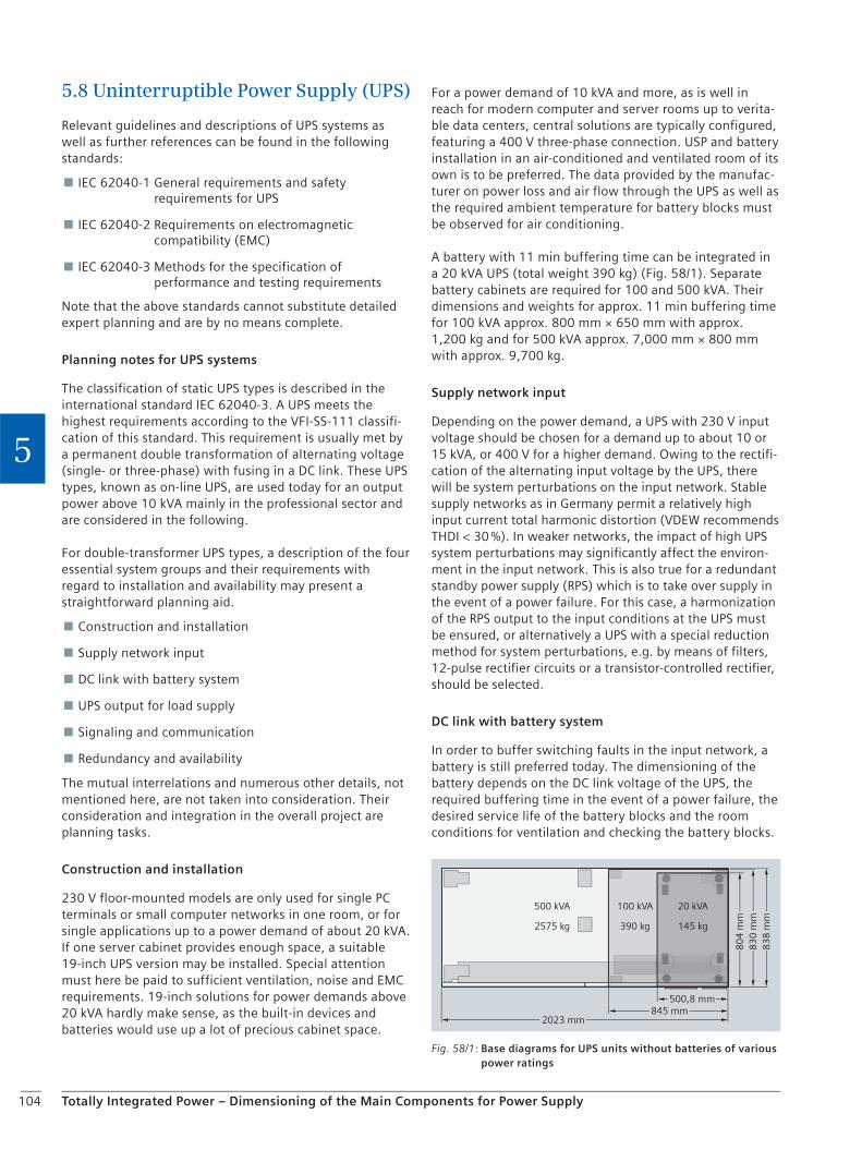
104 Totally Integrated Power – Dimensioning of the Main Components for Power Supply
5
5.8 Uninterruptible Power Supply (UPS)
Relevant guidelines and descriptions of UPS systems as well as further references can be found in the following standards:
IEC 62040-1 General requirements and safety requirements for UPS
IEC 62040-2 Requirements on electromagnetic compatibility (EMC)
IEC 62040-3 Methods for the specification of performance and testing requirements
Note that the above standards cannot substitute detailed expert planning and are by no means complete.
Planning notes for UPS systems
The classification of static UPS types is described in the international standard IEC 62040-3. A UPS meets the highest requirements according to the VFI-SS-111 classifi-cation of this standard. This requirement is usually met by a permanent double transformation of alternating voltage (single- or three-phase) with fusing in a DC link. These UPS types, known as on-line UPS, are used today for an output power above 10 kVA mainly in the professional sector and are considered in the following.
For double-transformer UPS types, a description of the four essential system groups and their requirements with regard to installation and availability may present a straightforward planning aid.
Construction and installation
Supply network input
DC link with battery system
UPS output for load supply
Signaling and communication
Redundancy and availability
The mutual interrelations and numerous other details, not mentioned here, are not taken into consideration. Their consideration and integration in the overall project are planning tasks.
Construction and installation
230 V floor-mounted models are only used for single PC terminals or small computer networks in one room, or for single applications up to a power demand of about 20 kVA. If one server cabinet provides enough space, a suitable 19-inch UPS version may be installed. Special attention must here be paid to sufficient ventilation, noise and EMC requirements. 19-inch solutions for power demands above 20 kVA hardly make sense, as the built-in devices and batteries would use up a lot of precious cabinet space.
For a power demand of 10 kVA and more, as is well in reach for modern computer and server rooms up to verita-ble data centers, central solutions are typically configured, featuring a 400 V three-phase connection. USP and battery installation in an air-conditioned and ventilated room of its own is to be preferred. The data provided by the manufac-turer on power loss and air flow through the UPS as well as the required ambient temperature for battery blocks must be observed for air conditioning.
A battery with 11 min buffering time can be integrated in a 20 kVA UPS (total weight 390 kg) (Fig. 58/1). Separate battery cabinets are required for 100 and 500 kVA. Their dimensions and weights for approx. 11 min buffering time for 100 kVA approx. 800 mm × 650 mm with approx. 1,200 kg and for 500 kVA approx. 7,000 mm × 800 mm with approx. 9,700 kg.
Supply network input
Depending on the power demand, a UPS with 230 V input voltage should be chosen for a demand up to about 10 or 15 kVA, or 400 V for a higher demand. Owing to the rectifi-cation of the alternating input voltage by the UPS, there will be system perturbations on the input network. Stable supply networks as in Germany permit a relatively high input current total harmonic distortion (VDEW recommends THDI < 30 %). In weaker networks, the impact of high UPS system perturbations may significantly affect the environ-ment in the input network. This is also true for a redundant standby power supply (RPS) which is to take over supply in the event of a power failure. For this case, a harmonization of the RPS output to the input conditions at the UPS must be ensured, or alternatively a UPS with a special reduction method for system perturbations, e.g. by means of filters, 12-pulse rectifier circuits or a transistor-controlled rectifier, should be selected.
DC link with battery system
In order to buffer switching faults in the input network, a battery is still preferred today. The dimensioning of the battery depends on the DC link voltage of the UPS, the required buffering time in the event of a power failure, the desired service life of the battery blocks and the room conditions for ventilation and checking the battery blocks.
500,8 mm845 mm
80
4 m
m
2023 mm
100 kVA
390 kg
20 kVA
145 kg
500 kVA
2575 kg
83
0 m
m8
38
mm
Fig. 58/1: Base diagrams for UPS units without batteries of various power ratings
105Totally Integrated Power – Dimensioning of the Main Components for Power Supply
5
Single-block monitoring can reduce service overheads on the one hand and increase the reliability of battery power availability on the other.
UPS output for load supply
Besides the required active power, the load-side power rating for a UPS system also takes the phase interrelations between output voltage and current into account. By means of suitable filtering measures to improve the output voltage quality, UPS output currents may be emitted phase-delayed towards voltage waves. Many of the power supply units nowadays integrated in computers and serv-ers show this power input quality which is characterized by a so-called “inductive power factor” (for lagging current wave) between 0.6 and 0.9. However, modern power supply units are provided with a “power factor compensa-tion” so that phase displacement does not occur any more and pure active power is taken in by the UPS. If loads requiring large capacitors, e.g. for filtering, are connected to the UPS, the entire load system may also have a so-called capacitive load performance factor (current wave leading voltage wave), which must be taken into account for UPS sizing.
The possibilities for selective protection upstream and downstream of the UPS, and the short-circuit behavior of the UPS have an impact on power distribution in the load network. What is important for UPS engineering is that the option of a bypass for safe triggering of a short-circuit fuse is also included in the planning.
Signaling and communication
For a decentralized UPS in an office, an LED display and an acoustic signal meets the essential requirements on signal-ing UPS status, load requirements and alarms. A serial interface (possibly a USB port) should be provided for PC-based monitoring and parameterization.
In a central UPS arrangement, the monitoring unit is rarely in the installation room, so that interfacing to a data network, such as Ethernet per SNMP, or an industrial network like PROFIBUS must be possible. The same applies to emergency signaling using floating contacts with suit-able connections. When UPS telemonitoring is outsourced to the UPS manufacturer or its representative, the UPS can communicate with the service center via a separate tele-phone line. Active “messaging” – in which the UPS immedi-ately signals problems and faults upon occurrence, inform-ing competent authorities, such as the service center, technician and the data center operator, if necessary, by a sequence of measures – would be the optimal solution.
Redundancy and availability
In addition to the quality of the individual components, the availability can be increased through redundancy. The redundancy can be distributed among the component or device redundancy and the system or route redundancy. If
several components or devices can perform a function and this function is not impaired when a fault occurs in an individual component or device, then the redundancy is called (N+1), as N components or units are required to ensure availability. Redundancy of components in a device is called "internal redundancy". In a "mirrored" arrange-ment for high-security applications, the complete UPS system is built in parallel, as (N+N) redundancy. (N+1) redundancy for the individual system can also be provided here, for example, (N+1)+(N+1) redundancy. Systematic errors and faults in routes and supplies can also result in the failure of the UPS protection. With the N+N redun-dancy, two separate systems provide a high level of avail-ability as when a failure occurs in one system route or in a component, the task can be taken over by the second system without a problem. (N+1)+(N+1) redundancy can be selected for component or device redundancy in addi-tion to the system redundancy.
An important feature when considering redundancy in detail is "diversity". It is better when devices and compo-nents use different operating principles so that when there is a systematic malfunction, both systems do not fail simultaneously. One example is the different stored energy features for the UPS DC link. The battery is a chemical storage module, while the flywheel uses rotational energy and the super capacitor stores the electric charge.
The following must be taken into account when planning the UPS:
Power system configuration for the input network; power quality and input power factor
System perturbation problem at the UPS input
Load on safe busbar; planned reserve for rated power
Parallel connection; centrally operated, manual bypass for servicing
Power factor of the connected loads
Battery: buffering time, service life, maintenance, location
Ventilation, air conditioning, cable sizing
Communication link and shutdown functionality
106
Checklist
Totally Integrated Power – Dimensioning of the Main Components for Power Supply
5
Basic specifications for the UPS system
Rated power, load-side
Active power required . . . . . . . . . . . . . . . . . . . . kVA
Apparent power required . . . . . . . . . . . . . . . . . . . . kW
Load power factor required (cos φ) . . . . . . . . . . . . . . . . . . . . cap. / ind.
Voltage and frequency, system configuration . . . . . . . . . . . . . . . . . . . . V , Hz
Input supply
Power supply source (generator, transformer),
number of inputs . . . . . . . . . . . . . . . . . . . .
Permissible system perturbations . . . . . . . . . . . . . . . . . . . . % THDi
Voltage and frequency, system configuration . . . . . . . . . . . . . . . . . . . . V , Hz
Installation and environment c Central installation in separate room (dimensions)
c Decentralized, 19-inch computer, network, server cabinets
c Decentralized, floor-mounted in the computer or office room
Electromagnetic compatibility . . . . . . . . . . . . . . . . . . . . e.g. Class C1, C2, C3
Noise . . . . . . . . . . . . . . . . . . . . dBA in 1 m
Climatic conditions
(room temperature, ventilation, …) . . . . . . . . . . . . . . . . . . . . °C, m3 air flow
Buffering time, shutdown and monitoring
107
Checklist
Totally Integrated Power – Dimensioning of the Main Components for Power Supply
5
Battery buffering time at 100 % load . . . . . . . . . . . . . . . . . . . . min
Battery service life . . . . . . . . . . . . . . . . . . . . years
Battery capacity . . . . . . . . . . . . . . . . . . . . Ah
DC link voltage . . . . . . . . . . . . . . . . . . . . V
Signaling c Serial c USB c Ethernet
c Contacts c PROFIBUS c Modbus / JBus
Shutdown c Single system c Parallel / redundancy systems
c Central monitoring of several separate systems
Alarm and messaging system c
Telemonitoring c
Redundancy
No redundancy c N (sufficient to supply load)
Redundancy of the devices c N+1 (N devices are sufficient for load supply)
Redundancy of the systems c N+N (2 separate systems that independently supply the load)
Redundancy for devices and systems c (N+1) + (N+1) (2 separate systems, each of which contains
one more device than necessary)

108 Totally Integrated Power – Dimensioning of the Main Components for Power Supply
5
5.9 Standby Power Supply
The use of a redundant power supply for the purpose of supplying power when the public supply fails may be required for several reasons, for example:
To fulfill statutory regulations for installations for gathering of people, hospitals or similar buildings
Official or statutory regulations for the operation of high-rise buildings, offices, workplaces, large garages or similar buildings
To ensure operation of safety-relevant systems such as sprinkler systems, smoke evacuation systems, control and monitoring systems or similar systems
To ensure operation of IT systems
To safeguard production processes in industry
To cover peak loads or to complement power supply system
5.9.1 Basic Terms
General
First, a distinction is made between a power generating unit and a power generating station. The power generat-ing unit is only the actual machine unit comprising drive motor, generator, power transmission elements and stor-age elements. The power generating station also contains the auxiliary equipment such as exhaust system, switch-gear and the installation room. This is then a complete redundant power supply. The purpose of use and the design have not been taken into account yet.
Operating modes
A distinction is made between continuous operation, time-limited continuous operation and pure emergency operation during the operation or use of redundant power supplies. The unlimited continuous operation enables the operation of a redundant power supply, theoretically for an unlimited time and without interruption. This operating mode is only very rarely used in regions supplied through-out by power supply companies. Equipment that enables long maintenance intervals for the redundant power supply or the continuous operation system must also be taken into account for this mode. Continuous operation for a limited time is the most frequent application for redun-dant power supplies. The maximum operation time of the system and, in particular the drive motor, is limited.
This operating mode is useful for most applications, whereby an operation time of 1,000 h / a with a power reserve of 10 % is available (see DIN / ISO 3046 and 8528). Pure emergency power operation permits operation up to 500 h / a, but it is not possible to overload the system.
Standby state and version
The standby state of power generation stations or redun-dant power supplies differs according to systems without defined interruption time and systems with a defined, permissible interruption time. If there is no requirement with regard to the period between the power demand and the standby state or energy output, then a system without defined interruption time is used. Manual start of the redundant power supply is usually sufficient in this case. A maximum interruption time between the demand for power and the supply can be defined when required for production processes or by statutory regulations (DIN VDE 0100-710 or -718). These systems are usually started automatically.
The different permissible interruption times determine the generator unit variant. In most cases this is a standby generator unit, whereby the unit or system is started from standstill upon demand. The maximum permissible inter-ruption time is 15 s, for example.
In certain cases, a shorter interruption time is permitted.. Specially configured generator units must be used in order to be able to implement this shorter interruption time.
Criteria for use
The only distinction made here is between use on land and marine use. Marine use can be disregarded here. For use on land, appropriate variant classes are defined for the various application options.
5.9.2 Dimensioning of the Generator Units
DIN ISO 8528 applies for the dimensioning and manufac-turing of redundant supply generator units. The variant class of the generator unit results from the load demands (Table 59/1).
The following factors are important for the dimensioning of the generator units' rated power:
Sum of the connected loads = load capacity
Simultaneity factor
Turn-on behavior of the consumers
Dynamic response and load connection response of the generator unit
Environmental conditions at the installation site of the generator unit
Reserves for expansions
Short-circuit behavior

109Totally Integrated Power – Dimensioning of the Main Components for Power Supply
5
Load capacity
The load capacity results from the sum of the individual loads to be supplied. However, the electric apparent power must be used as the basis for the generator unit dimen-sioning. If necessary, only selected loads may be included in a generator unit supply in order to reduce the generator unit output.
Simultaneity factor
So-called simultaneity factors are used to determine the actual or realistic consumer load. The generator unit output is reduced by this factor. For values valid for the preliminary planning, see chapter 3.
Turn-on and operating behavior of consumers
The start-up and turn-on behavior of electric motors, transformers, large lighting systems with incandescent or similar lamps has a major effect on the generator unit output. Especially when there is a large proportion of critical consumers in relation to the generator unit output, an individual test must be performed.
The possibility of connecting loads or load groups in stages significantly reduces the required generator unit output. All the available possibilities of reducing the start-up loads of installed consumers should be fully exploited.
The operation of some consumer types can also have a major effect on the generator unit output and variant. A special test must be performed when supplying consumers with power electronic components (frequency converters, power converters, UPS systems).
Dynamic response
The dynamic response of the generator unit at full load connection and for the load changes to be expected must be adapted to the permissible values of the consumers. The variant class of the generator unit in accordance with DIN ISO 8528 is determined by the consumer type or the relevant regulations.
Fulfilling the required values can result in an overdimen-sioning of the engine, generator or both components. As a rule, modern diesel engines with turbochargers and possi-bly charge air cooling are mostly not suitable for load connections of approx. 60 to 100 % in one load impulse.
If no particular consumer-related requirements are made of the generator unit, the load connection must be per-formed in several stages.
Environmental conditions
The reference conditions for diesel motors must be taken into account here. According to DIN 6271, an ambient or air-intake temperature of 27 °C, a max. installation altitude of 1,000 m above sea level and a relative humidity of 60 % apply. If less favorable conditions are present at the instal-lation site of the generator unit, the diesel engine must be overdimensioned or the engine-specific derating factors must be taken into consideration.
Short-circuit behavior
If no particular measures are taken, the unit generators supply a three-pole sustained short-circuit current of approx. 3 to 3.5 × In at the generator terminals. If the respective generator unit system supplies large or compre-hensive networks, a larger short-circuit current may be required, e.g. for selectivity reasons. An overdimensioning of the generator is required in this case. As the active power may exceed the value of the rated generator unit power when a short-circuit occurs, the diesel engine may also have to be overdimensioned in this case.
Table 59/1: Generator-unit-specific operating values in accordance with DIN ISO 8528
Variant class
1 2 3
Static frequency deviation ± [ %]
8 5 3
Dynamic frequency deviation ± [ %]
15 10 7
Static voltage deviation ± [ %]
5 2.5 1
Dynamic voltage deviation [ %]
– +22 / –18 +20 / –15
Sustained short-circuit current × In
– 3 3
110 Totally Integrated Power – Dimensioning of the Main Components for Power Supply
5
5.9.3 Cooling of the Generator Unit Engines
Diesel engines can be cooled in various ways. The basic motor cooling variant depends on the manufacturer-spe-cific equipment of the respective diesel engine. As differ-ent cooling methods and principles result in different building requirements, the cooling system should be firmly established. On the other hand, the engine cooling system variant is affected by the conditions at the installation site of the redundant power supply.
Air cooling
Cooling air is directed over a suitably constructed engine surface by a blower. This cooling method is only found on diesel engines up to approx. 100 kW.
Closed-circuit water cooling with built-on radiator and fan
Water-cooled diesel engines dissipate the waste engine heat via a water-glycol mixture that is led through the respective separate engine cooling system. The cooling water heated in the engine is cooled in a radiator. Diesel engines that have been designed for a built-on or front-mounted radiator have a fan driven directly by the engine. The required amount of air is blown through the radiator by this fan.
The radiant heat of the motor is dissipated by the air flow produced by the fan. The built-on radiator can also be equipped with a charge air cooler. Modern diesel engines are often equipped with turbochargers and charge air coolers. Depending on the design concept of the manufac-turer, the charge air circuit of a diesel engine can be de-signed for air or water cooling.
Separate installation of engine and cooling unit
Conditions in the building may require the radiator to be installed separately from the generator unit. In this case, the radiator fan is driven by an electric motor. Depending on the distance between the generator unit and the cool-ing unit, additional devices such as coolant pumps, inter-mediate heat exchangers, etc. may be required.
5.9.4 Room Layout and System Components
When planning the generator unit room, the local building regulations must be taken into account The planning of the generator unit room can also have a significant influ-ence on the acquisition costs of a redundant power supply.
The installation room should be selected according to the following criteria:
Short cable routes to the supply point (LVMD)
The room should be located as far away as possible from residential rooms, offices, etc. (offending noise)
Problem-free intake and exhaust of the required air flow rates
Arrangement of the air inlets / outlets taking into account the main wind direction
Problem-free routing of the required exhaust pipe
Easy access for moving in the components
The later generator unit room must be selected so that is it large enough to easily accommodate all the system components. Depending on the installation size, there should be 1 to 2 meters of access space around the generator unit.
The generator unit room should always have a temperature of at least + 10° C in order to prevent condensation and corrosion forming and to reduce the engine preheating (Fig. 59/1).
Foundation
Generally a flat, oil-resisting base with adequate load carrying capacity is sufficient for the installation of genera-tor units.
Separate foundations are usually only required for larger generator units or when there are special requirements because of the building structure.
Ventilation
Appropriate air flow rates are required for the ventilation and cooling depending on the size of the generator unit and the engine cooling method (Fig. 59/2).
The flow speed throughout the entire ventilation system should not exceed 6 m / s in order to avoid flow noise. The size of the air inlets and outlets or the entire air circulation is calculated from the required air volume and the flow speed.
111Totally Integrated Power – Dimensioning of the Main Components for Power Supply
5
The openings should be arranged so that warm exhaust air cannot be drawn in again (thermal short-circuit). The ventilation openings are closed with automatic or motor-driven shutters and with weather shields outdoors. If the required air flow rate cannot be achieved, the engine cooling may have to be moved out of the generator unit room (see Section "Cooling of the Generator Unit Engines").
Exhaust system
Exhaust systems should be as short and with as few changes of direction as possible.
Further statutory regulations, technical guidelines and specifications must be taken into account for the arrange-ment of the exhaust system, for example, within a building well or for free-standing outdoor chimneys.
The design of the actual exhaust pipe with regard to the required cross section results from the planned total length, the maximum exhaust volume and the permissible exhaust back-pressure. Fig 59/3 can be used as a rough guide to determine the pipe cross section.
Tank facilities
Diesel fuel or fuel oil can be used for diesel generator units. However, the customs and tax regulations must be taken into account when fuel oil is used.
There must be sufficient fuel storage capacity available when operating a redundant power supply with a diesel motor. In Germany, the regulations for setting up tank facilities and the regulations for storing flammable liquids must be observed – in particular the water resources management law (WHG), technical rules for waterendan-gering substances (TRwS 779) and the directive for facili-ties handling waterendangering substances (VAwS).
Each generator unit tank facility should have enough fuel for 8 hours of operation at full load (Fig. 59/4). Facilities that are subject to DIN VDE 0100-710 must be dimen-sioned for at least 24 hours of operation at full load. In tank facilities for emergency power supply, the fuel level must be at least 0.5 m above the injection pump of the diesel engine.
In many cases, in particular for systems in continuous operation. it may be better to divide the tank facilities into a 24-hour tank and a storage tank. The 24-hour tank then remains in the generator unit room with capacity to suit the available space. The storage tank can then be installed in another room or designed as overground tank for out-door installation or as underground tank. The 24-hour tank is refueled by means of an automatic filling device.
00 400 800 1200 1600 2000
20
40
60
80
100
120
140
160
kVA
m3
Fig. 59/1: Space requirements of a complete redundant power supply including soundproofing
00 400 800 1200 1600 2000
5
10
15
20
25
30
kVAm
3/s
Fig. 59/2: Estimated air flow rate required for cooling, room ventilation and combustion in relation to the rated power
00 400 800 1200 1600 2000
100
200
300
400
500
600
kVA
DN
Fig. 59/3: Rough determination of the pipe cross section in relation to the rated power
00 400 800 1200
I/h
1600 2000
50
100150200
250
300350400450
kVA
Fig. 59/4: Hourly fuel consumption in relation to the rated power
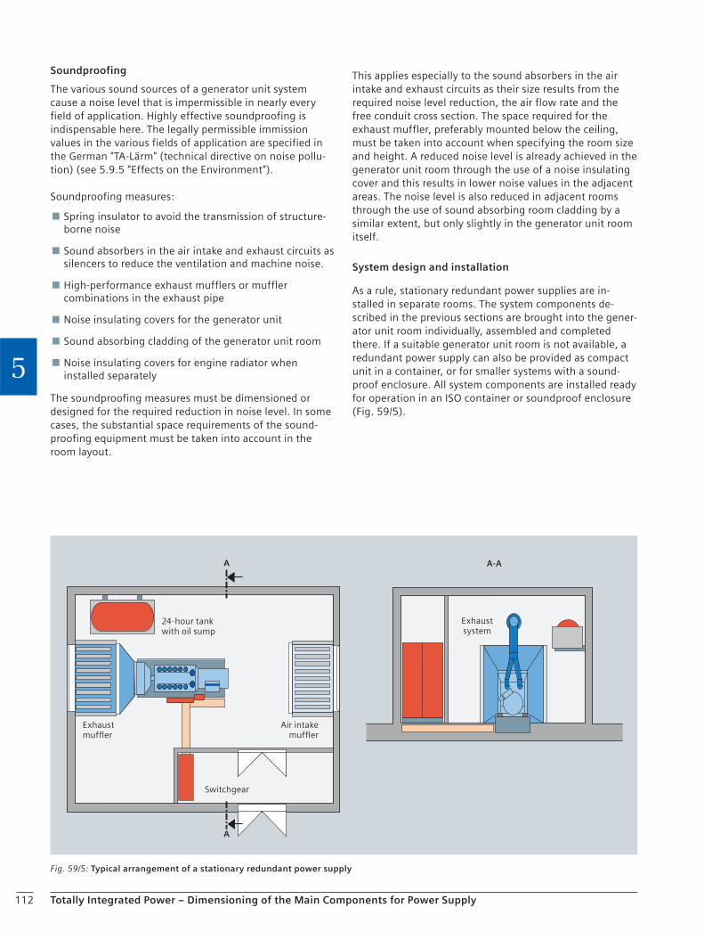
112 Totally Integrated Power – Dimensioning of the Main Components for Power Supply
5
Soundproofing
The various sound sources of a generator unit system cause a noise level that is impermissible in nearly every field of application. Highly effective soundproofing is indispensable here. The legally permissible immission values in the various fields of application are specified in the German "TA-Lärm" (technical directive on noise pollu-tion) (see 5.9.5 "Effects on the Environment").
Soundproofing measures:
Spring insulator to avoid the transmission of structure-borne noise
Sound absorbers in the air intake and exhaust circuits as silencers to reduce the ventilation and machine noise.
High-performance exhaust mufflers or muffler combinations in the exhaust pipe
Noise insulating covers for the generator unit
Sound absorbing cladding of the generator unit room
Noise insulating covers for engine radiator when installed separately
The soundproofing measures must be dimensioned or designed for the required reduction in noise level. In some cases, the substantial space requirements of the sound-proofing equipment must be taken into account in the room layout.
This applies especially to the sound absorbers in the air intake and exhaust circuits as their size results from the required noise level reduction, the air flow rate and the free conduit cross section. The space required for the exhaust muffler, preferably mounted below the ceiling, must be taken into account when specifying the room size and height. A reduced noise level is already achieved in the generator unit room through the use of a noise insulating cover and this results in lower noise values in the adjacent areas. The noise level is also reduced in adjacent rooms through the use of sound absorbing room cladding by a similar extent, but only slightly in the generator unit room itself.
System design and installation
As a rule, stationary redundant power supplies are in-stalled in separate rooms. The system components de-scribed in the previous sections are brought into the gener-ator unit room individually, assembled and completed there. If a suitable generator unit room is not available, a redundant power supply can also be provided as compact unit in a container, or for smaller systems with a sound-proof enclosure. All system components are installed ready for operation in an ISO container or soundproof enclosure (Fig. 59/5).
Fig. 59/5: Typical arrangement of a stationary redundant power supply
24-hour tank with oil sump
Exhaustmuffler
Air intakemuffler
Switchgear
Exhaustsystem
A A-A
A
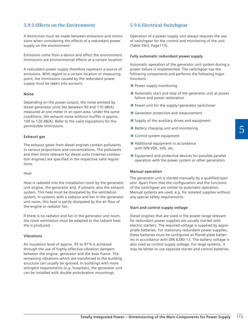
113Totally Integrated Power – Dimensioning of the Main Components for Power Supply
5
5.9.5 Effects on the Environment
A distinction must be made between emissions and immis-sions when considering the effects of a redundant power supply on the environment:
Emissions come from a device and affect the environment. Immissions are environmental effects at a certain location.
A redundant power supply therefore represent a source of emissions. With regard to a certain location or measuring point, the immissions caused by the redundant power supply must be taken into account.
Noise
Depending on the power output, the noise emitted by diesel generator units lies between 90 and 110 dB(A) measured at one meter in an open area. Under the same conditions, the exhaust noise without muffler is approx. 100 to 120 dB(A). Refer to the valid regulations for the permissible immissions.
Exhaust gas
The exhaust gases from diesel engines contain pollutants in various proportions and concentrations. The pollutants and their limits relevant for diesel units (internal combus-tion engines) are specified in the respective valid regula-tions.
Heat
Heat is radiated into the installation room by the generator unit engine, the generator and, if present, also the exhaust system. This heat must be dissipated by the ventilation system, In systems with a radiator and fan in the generator unit room, this heat is partly dissipated by the air flow of the engine or radiator fan.
If there is no radiator and fan in the generator unit room, the room ventilation must be adapted to the radiant heat the is produced.
Vibrations
An insulation level of approx. 95 to 97 % is achieved through the use of highly-effective vibration dampers between the engine, generator and the base frame. The remaining vibrations which are transferred to the building structure can usually be ignored. In buildings with more stringent requirements (e.g. hospitals), the generator unit can be installed with double anitvibration mountings.
5.9.6 Electrical Switchgear
Operation of a power supply unit always requires the use of switchgear for the control and monitoring of the unit (Table 59/3, Page115).
Fully automatic redundant power supply
Automatic operation of the generator unit system during a power failure is implemented. The switchgear has the following components and performs the following major functions:
Power supply monitoring
Automatic start and stop of the generator unit at power failure and power restoration
Power unit for the supply / generator switchover
Generator protection and measurement
Supply of the auxiliary drives and equipment
Battery charging unit and monitoring
Control system equipment
Additional equipment in accordance with DIN VDE, VdS, etc.
Equipment and protective devices for possible parallel operation with the power system or other generators
Manual operation
The generator unit is started manually by a qualified oper-ator. Apart from that the configuration and the functions of the switchgear are similar to automatic operation. Manual systems are used, e.g. for isolated supplies without any special safety requirements.
Start and control supply voltage
Diesel engines that are used in the power range relevant for redundant power supplies are usually started with electric starters. The required voltage is supplied by appro-priate batteries. For stationary redundant power supplies, these batteries must be configured as Planté-plate batter-ies in accordance with DIN 6280-13. The battery voltage is also used as control supply voltage. For large systems, it may be better to use separate starter and control batteries.
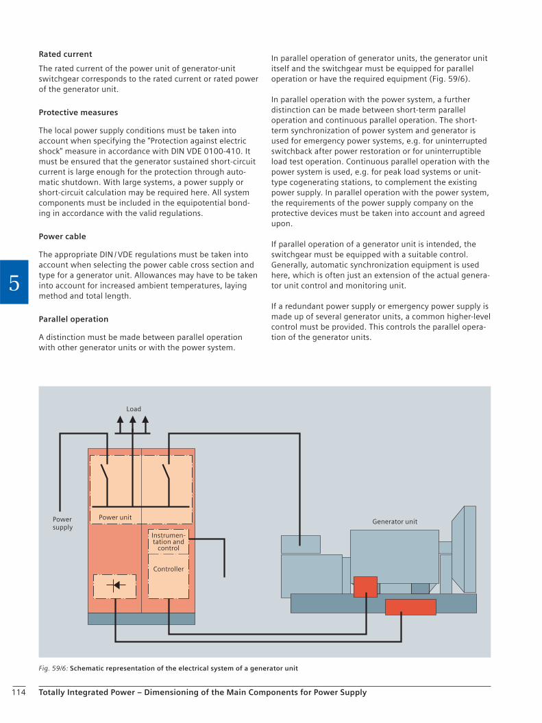
114 Totally Integrated Power – Dimensioning of the Main Components for Power Supply
5
Rated current
The rated current of the power unit of generator-unit switchgear corresponds to the rated current or rated power of the generator unit.
Protective measures
The local power supply conditions must be taken into account when specifying the "Protection against electric shock" measure in accordance with DIN VDE 0100-410. It must be ensured that the generator sustained short-circuit current is large enough for the protection through auto-matic shutdown. With large systems, a power supply or short-circuit calculation may be required here. All system components must be included in the equipotential bond-ing in accordance with the valid regulations.
Power cable
The appropriate DIN / VDE regulations must be taken into account when selecting the power cable cross section and type for a generator unit. Allowances may have to be taken into account for increased ambient temperatures, laying method and total length.
Parallel operation
A distinction must be made between parallel operation with other generator units or with the power system.
In parallel operation of generator units, the generator unit itself and the switchgear must be equipped for parallel operation or have the required equipment (Fig. 59/6).
In parallel operation with the power system, a further distinction can be made between short-term parallel operation and continuous parallel operation. The short-term synchronization of power system and generator is used for emergency power systems, e.g. for uninterrupted switchback after power restoration or for uninterruptible load test operation. Continuous parallel operation with the power system is used, e.g. for peak load systems or unit-type cogenerating stations, to complement the existing power supply. In parallel operation with the power system, the requirements of the power supply company on the protective devices must be taken into account and agreed upon.
If parallel operation of a generator unit is intended, the switchgear must be equipped with a suitable control. Generally, automatic synchronization equipment is used here, which is often just an extension of the actual genera-tor unit control and monitoring unit.
If a redundant power supply or emergency power supply is made up of several generator units, a common higher-level control must be provided. This controls the parallel opera-tion of the generator units.
Fig. 59/6: Schematic representation of the electrical system of a generator unit
Load
Instrumen-tation and
control
Power unit
Controller
Generator unitPowersupply
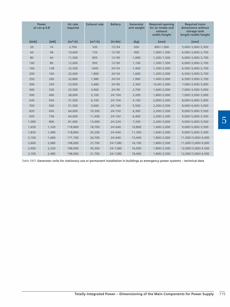
115Totally Integrated Power – Dimensioning of the Main Components for Power Supply
5
Table 59/3: Generator units for stationary use or permanent installation in buildings as emergency power systems – technical data
Powerat cos φ 0.8
[kVA] [kW]
Air rate required
[m3 / h]
Exhaust rate
[m3 / h]
Battery
[V / Ah]
Generator unit weight
[kg]
Required opening for air intake and
exhaustwidth / height
[mm]
Required room dimensions without
storage tanklength / width / height
[mm]
20 16 2,700 320 12 / 54 650 800 / 1,000 5,000 / 3,000 / 2,500
60 48 10,600 720 12 / 90 900 1,000 / 1,500 6,000 / 3,000 / 2,700
80 64 11,500 850 12 / 90 1,000 1,200 / 1,500 6,000 / 3,000 / 2,700
100 80 12,000 950 12 / 90 1,100 1,200 / 1,500 6,000 / 3,000 / 2,700
160 128 22,500 1640 24 / 54 1,400 1,200 / 2,000 6,500 / 3,000 / 2,700
200 160 22,600 1,800 24 / 54 1,600 1,200 / 2,000 6,500 / 3,000 / 2,700
250 200 22,800 1,980 24 / 54 1,900 1,400 / 2,000 6,500 / 3,000 / 2,700
300 240 23,000 3,680 24 / 90 2,300 16,00 / 2,000 7,000 / 3,500 / 3,000
400 320 23,500 4,900 24 / 90 2,700 1,600 / 2,000 7,000 / 3,500 / 3,000
500 400 28,000 5,100 24 / 104 3,200 1,800 / 2,000 7,000 / 3,500 / 3,000
630 504 31,500 6,100 24 / 104 4,100 2,000 / 2,500 8,000 / 4,000 / 3,000
700 560 51,500 9,000 24 / 160 5,500 2,200 / 2,500 8,000 / 4,000 / 3,000
820 656 64,000 10,300 24 / 192 6,300 2,200 / 2,500 9,000 / 5,000 / 3,500
920 736 64,000 11,400 24 / 192 6,400 2,200 / 2,500 9,000 / 5,000 / 3,500
1,000 800 81,000 13,000 24 / 224 7,200 2,200 / 3,000 9,000 / 5,000 / 3,500
1,650 1,320 118,800 18,700 24 / 640 10,800 1,600 / 2,000 9,000 / 5,000 / 3,500
1,850 1,480 118,800 20,200 24 / 640 11,300 1,600 / 2,000 9,000 / 5,000 / 3,500
2,100 1,680 171,700 26,700 24 / 640 13,400 1,800 / 2,000 11,000 / 5,000 / 4,000
2,600 2,080 198,000 27,700 24 / 1280 16,100 1,800 / 2,500 11,000 / 5,000 / 4,000
2,900 2,320 198,000 30,300 24 / 1280 16,900 1,800 / 2,500 12,000 / 5,000 / 4,500
3,100 2,480 198,000 31,700 24 / 1280 18,400 1,800 / 2,500 12,000 / 5,000 / 4,500

116
Checklist
Totally Integrated Power – Dimensioning of the Main Components for Power Supply
5
Power generation units
Project name . . . . . . . . . . . . . . . . . . . . . . . . . . . . . . . . . . . . . . . . . . . . . . . . . . . . . . .
. . . . . . . . . . . . . . . . . . . . . . . . . . . . . . . . . . . . . . . . . . . . . . . . . . . . . . .
Owner / developer . . . . . . . . . . . . . . . . . . . . . . . . . . . . . . . . . . . . . . . . . . . . . . . . . . . . . . .
. . . . . . . . . . . . . . . . . . . . . . . . . . . . . . . . . . . . . . . . . . . . . . . . . . . . . . .
Planning engineer . . . . . . . . . . . . . . . . . . . . . . . . . . . . . . . . . . . . . . . . . . . . . . . . . . . . . . .
Generator unit output . . . . . . . . . . . . . . . . . . . . kW
Power that must be substituted immediately after power failure . . . . . . . . . . . . . . . . . . . . kW
Notes on consumers (heavy starting or special features, e.g. UPS) . . . . . . . . . . . . . . . . . . . . . . . . . . . . . . . . . . . . . . . . . . . . . . . . . . . . . . .
UPS load . . . . . . . . . . . . . . . . . . . . VA
Rated voltage, rated frequency . . . . . . . . . . . . . . . . . . . . V . . . . . . . . . . . . . . . . . . . . Hz
Power factor, number of phases . . . . . . . . . . . . . . . . . . . . (cos φ) . . . . . . . . . . . . . . . . . . . .
Power supply system c TN-S c TN-S (EMC-friendly)
c TN-C c TN-C-S c TT c IT
Fuel c Diesel fuel c Gasoline c Gas
Required operating time at rated power without refueling . . . . . . . . . . . . . . . . . . . . h
Type of cooling for combustion engine c Air cooling c Liquid cooling
Operating mode c Time-limited operation c Emergency power unit
c Peak load unit c Stand-alone
c Parallel operation with other power generating units
Expected operating hours . . . . . . . . . . . . . . . . . . . . hours per annum
Installation c Stationary c Transportable c Mobile
Effects of weather c Indoor c Outdoor c Open air installation
Ambient temperature, installation altitude (above sea level) . . . . . . . . . . . . . . . . . . . . °C . . . . . . . . . . . . . . . . . . . . m
Air pollution c Sand / dust c Chemicals
Noise limit (maximum level) . . . . . . . . . . . . . . . . . . . . dB
Emissions . . . . . . . . . . . . . . . . . . . .
Exhaust gas emission limits . . . . . . . . . . . . . . . . . . . .
Chapter 6Building Management, Comfort and HVAC
6.1 Building Automation with Desigo 118
6.2 Heating, Ventilation, Air Conditioning (HVAC) 120
6.3 Planning Notes for GAMMA instabus (KNX / EIB) 123
6.4 Power Management 125
6.5 SICAM Power I&C System 134

118 Totally Integrated Power – Building Management, Comfort and HVAC
66.1 Building Automation with Desigo
Building automation and security management are part of the technical building management.
The main task of the technical building management is the management of the subsystems. This comprises in particu-lar the central monitoring and operation of the subsystems but also the option of visualization, archiving, logging, and evaluation.
The pyramid shown in Fig. 61/1 reflects the data concen-tration which arises from one level to the next: The field level acquires a great deal of information of which, how-ever, only the relevant part is passed on to the next level. A typical example for that are intelligent fire detectors which continuously record the smoke density and temperature, for example, but only periodically signal a degree of dan-ger to the control center, and only in the case of an alarm immediately report the event to the control center.
Main requirements for a building management system
Scalable system structure
When selecting a building management system (BMS), it must be made sure that it provides sufficient support for future alterations and extensions. The stepwise expand-ability of a system and the correspondingly simple and efficient system expansion form a central quality charac-teristic.
To allow for a better structuring of the diversity of techni-cal systems, it is worth taking a closer look at the various building management tasks. Usually, the following three task areas are distinguished:
Commercial management is performed by specialized systems which support the company's business processes and comprises various subareas from purchasing to logistics to sales and maintenance. These systems are more or less integrated, depending on the solution, and can be combined under the name ERP (Enterprise Resource Planning). Among the most well known companies in this field are SAP and Oracle, for example.
6 Building Management, Comfort and HVAC
Infrastructural building management comprises, among other things, systems for the maintenance of the building, e.g. the facility management systems (FMS) which manage the maintenance of the technical facilities.
Technical building management comprises the building automation and security management. While the building automation deals with, for example, heating, ventilation, air conditioning (HVAC), light and lifts, the security management deals with fire detection, burglar alarm, access control, video surveillance, and other security topics.
Openness by standards
To support open communication, standard interfaces and protocols such as BACnet, KNX / EIB Profinet and others are provided for a direct integration of subsystems into the management station.
Economic efficiency
Functionality and user-friendliness are supposed to reduce operating expense and training time and increase the productivity at a simultaneously high operational safety.
Fig. 61/1: Structure of the technical building management
Planning of the company resources (ERP)
Fieldlevel
Automationlevel
Technical building management
Total Building Solutions

119Totally Integrated Power – Building Management, Comfort and HVAC
6
The operating behavior of the systems can be optimized in a simple manner via the management station and provides for an energy-efficient operation of the entire building installations.
Main functions of the building management system
Operator control and monitoring Fast and selective monitoring and operation of the system with practical plant and room diagrams.
Time programs Central programming of all time-controlled building functions.
Alarm handling Detailed overview of the alarms for a fast localization and elimination of faults. Central elements of the alarm handling are therefore the danger identification, danger alarm and an adequate intervention. This is supported by the flexible transmission of alarms to mobile devices, e.g. printers or pagers.
Event control System-wide monitoring of systems and processes with regard to the occurrence of certain criteria for the triggering of certain predefined actions. Reporting Modern management stations today work with integrated database applications. This allows for the storage of an almost unlimited number of past events and their recorded handling. With these plant-specific records and the corresponding query options, the following questions can be answered, for example:
What has happened in the past 24 hours? – How many interferences occurred within a certain –period? Who has done what and when following yesterday's –burglar alarm?
To provide this main function, a whole range of additional functions is required, which so to speak forms the infra-structure of the building management system. The most important of these additional functions are, for example: access rights concept, user administration, password administration, object management in tree and graphic structures, and graphic level management.
6.1.2 Planning of a Building Management System
Within the scope of BMS projects, there are individual project phases comprising different contents and responsibilities. The first project phases are described in the following.
Definition of objectives
The customer / user must define objectives, this serves as a basis for the preparation of a requirements specification. The definition of objectives comprises the following ele-ments:
Scope of the building automation and security management subsystems to be integrated.
Definition of the integration: Combining all subsystems of building installations (fire alarm, gas warning, burglar alarm, access control or video surveillance, HVAC systems, lighting, and further external systems) by integrating them into a building management system brings the following advantages:
Improved overview and thus increased safety. – Lower costs in comparison to several independent –control centers with regard to acquisition, configuration, and maintenance. Consistent operational concept and thus less training –time and effort, and no danger of confusion in an emergency. Only one system has to be integrated into the in- –house IT infrastructure. Interactions between the subsystems are possible in a –much easier way. Alarm escalation and alarm transmission is done in a –more uniform way. Integrated video systems allow for a direct view of the –fault cause.
The objective is therefore to integrate all subsystems as completely as possible into the building management system.
Expected improvements compared to a single-system solution.
Demands on the failure safety (redundancy solutions).
Demands on the power supply (e.g. UPS).
Description of the workplaces and tasks of the employees at the workplaces.
From the definition of objectives, a requirements specifica-tion has to be prepared with the collaboration of the user and planner.
120 Totally Integrated Power – Building Management, Comfort and HVAC
6
Requirements specification
Within the scope of the requirements specification, the completeness and clarity of the definition of objectives is verified. The following details need to be substantiated:
Which installations / systems do already exist and have to be integrated into the overall system (specifying the software version)?
Which installations / systems have to be acquired newly, makes or description of the systems and the expected interface for the integration?
Amount of data points
Functional description (alarm plans, automation demands, action plans, graphics, operational concepts, etc.)
Definition of the expected performance features
Definition of the technical framework conditions for the integration: Part of that is the description of the expected physical and logical interfaces to include them in the defined integration for a holistic management system.
Description of the mode of operation of subsystems
Definition of time synchronizations, ramp-up behavior and synchronization, system monitoring and safety-related requirements
Definition of the regulatory framework conditions: Part of this are topics like: licensing rights, disclosure of interfaces, support in the new development or adaptation as well as the commissioning of the interfaces.
Conceptual solution (block diagram) with regard to the networking of the subsystems and management system to be connected
Specification of the graphical user interface with the objective to obtain a uniform picture for the entire building and all installations, with the same detail sharpness and the same information content as well as the same viewing angles and brightness.
Framework conditions
In the framework conditions, all other conditions referring to the project have to be specified. The requirements specification and the framework conditions serve as a basis for invitations to tender, selection and project monitoring.
6.2 Heating, Ventilation, Air Conditioning (HVAC)A reduction of the energy consumption as it is requested by standards and regulations in various European countries can be achieved by applying tight windows and corre-spondingly insulated brickwork. Nevertheless, if the neces-sary air exchange is not ensured, there is a danger of bad air quality in rooms due to humidity, radon, organic mat-ters, formaldehyde and other effluviums from building materials, fitments, etc. The inhabitants' well-being is not only impaired by this, but there is also the danger of struc-tural damage, primarily caused by the growth of mold.
In a highly isolated building, window ventilation is not only insufficient but also renders void all efforts to save energy. Therefore, the installation of a ventilation system should be considered in any case.
Ventilation and air conditioning systems which are able to keep a specified air state with regard to temperature and humidity throughout the year are called air-conditioning systems. These systems are equipped with all necessary components which allow for heating, cooling, humidifying or dehumidifying the air as required.
The necessity for the use of an air-conditioning system has to be considered in each case. The following specifications might necessitate air conditioning:
Heat, oppressiveness
Architectural specifications such as large banks of windows, open-plan offices, lack of shading, etc.
Stringent demands on temperature and humidity
Interior rooms, assembly rooms
High thermal loads
EDP, machine rooms
Tasks of the HVAC systems
Depending on the purpose, the tasks of the HVAC systems can be subdivided in two subareas:
Comfort systems: The term 'comfort systems' combines all systems creating and automatically maintaining a comfortable room climate which supports people's health and performance in our residential buildings, offices, schools, hospitals, restaurants, cinemas, theaters, department stores, etc.
Industrial systems: The term 'industrial systems' combines all systems creating and maintaining a room climate or room state in order to ensure certain production processes, storage or ripening processes.
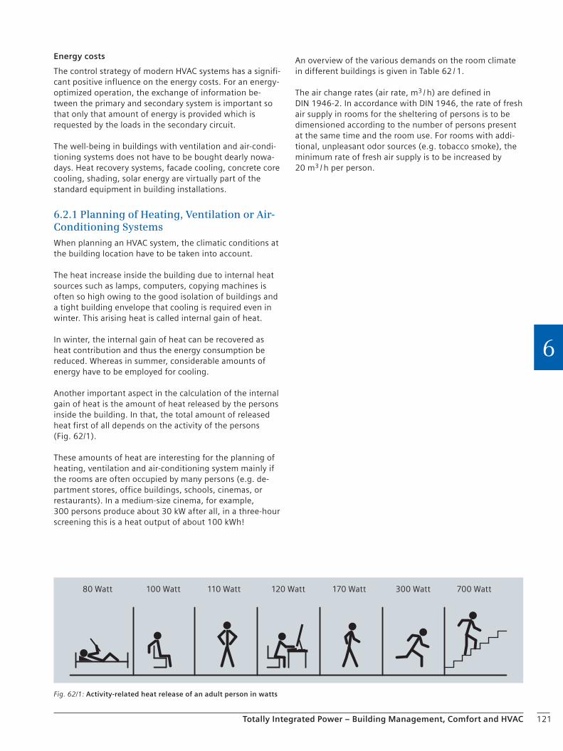
121Totally Integrated Power – Building Management, Comfort and HVAC
6
Energy costs
The control strategy of modern HVAC systems has a signifi-cant positive influence on the energy costs. For an energy-optimized operation, the exchange of information be-tween the primary and secondary system is important so that only that amount of energy is provided which is requested by the loads in the secondary circuit.
The well-being in buildings with ventilation and air-condi-tioning systems does not have to be bought dearly nowa-days. Heat recovery systems, facade cooling, concrete core cooling, shading, solar energy are virtually part of the standard equipment in building installations.
6.2.1 Planning of Heating, Ventilation or Air-Conditioning Systems
When planning an HVAC system, the climatic conditions at the building location have to be taken into account.
The heat increase inside the building due to internal heat sources such as lamps, computers, copying machines is often so high owing to the good isolation of buildings and a tight building envelope that cooling is required even in winter. This arising heat is called internal gain of heat.
In winter, the internal gain of heat can be recovered as heat contribution and thus the energy consumption be reduced. Whereas in summer, considerable amounts of energy have to be employed for cooling.
Another important aspect in the calculation of the internal gain of heat is the amount of heat released by the persons inside the building. In that, the total amount of released heat first of all depends on the activity of the persons (Fig. 62/1).
These amounts of heat are interesting for the planning of heating, ventilation and air-conditioning system mainly if the rooms are often occupied by many persons (e.g. de-partment stores, office buildings, schools, cinemas, or restaurants). In a medium-size cinema, for example, 300 persons produce about 30 kW after all, in a three-hour screening this is a heat output of about 100 kWh!
An overview of the various demands on the room climate in different buildings is given in Table 62 / 1.
The air change rates (air rate, m3 / h) are defined in DIN 1946-2. In accordance with DIN 1946, the rate of fresh air supply in rooms for the sheltering of persons is to be dimensioned according to the number of persons present at the same time and the room use. For rooms with addi-tional, unpleasant odor sources (e.g. tobacco smoke), the minimum rate of fresh air supply is to be increased by 20 m3 / h per person.
80 Watt 100 Watt 110 Watt 120 Watt 170 Watt 300 Watt 700 Watt
Fig. 62/1: Activity-related heat release of an adult person in watts
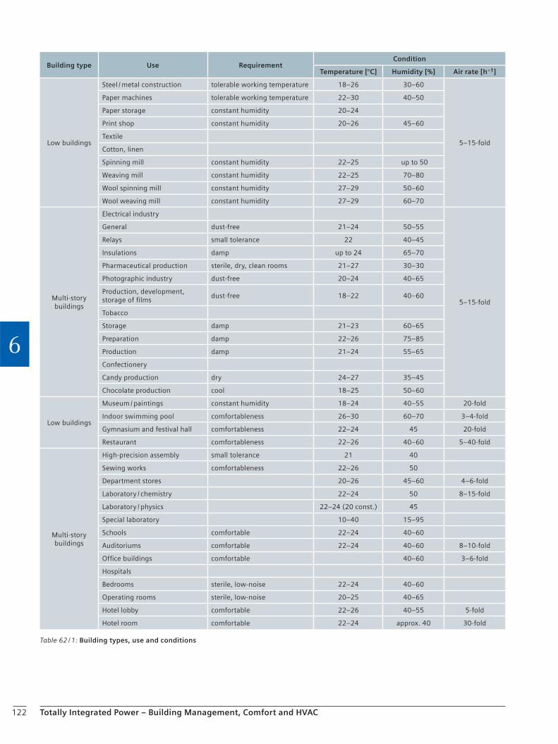
122 Totally Integrated Power – Building Management, Comfort and HVAC
6
Table 62 / 1: Building types, use and conditions
Building type Use RequirementCondition
Temperature [°C] Humidity [%] Air rate [h–1]
Low buildings
Steel / metal construction tolerable working temperature 18–26 30–60
5–15-fold
Paper machines tolerable working temperature 22–30 40–50
Paper storage constant humidity 20–24
Print shop constant humidity 20–26 45–60
Textile
Cotton, linen
Spinning mill constant humidity 22–25 up to 50
Weaving mill constant humidity 22–25 70–80
Wool spinning mill constant humidity 27–29 50–60
Wool weaving mill constant humidity 27–29 60–70
Multi-story buildings
Electrical industry
5–15-fold
General dust-free 21–24 50–55
Relays small tolerance 22 40–45
Insulations damp up to 24 65–70
Pharmaceutical production sterile, dry, clean rooms 21–27 30–30
Photographic industry dust-free 20–24 40–65
Production, development, storage of films
dust-free 18–22 40–60
Tobacco
Storage damp 21–23 60–65
Preparation damp 22–26 75–85
Production damp 21–24 55–65
Confectionery
Candy production dry 24–27 35–45
Chocolate production cool 18–25 50–60
Low buildings
Museum / paintings constant humidity 18–24 40–55 20-fold
Indoor swimming pool comfortableness 26–30 60–70 3–4-fold
Gymnasium and festival hall comfortableness 22–24 45 20-fold
Restaurant comfortableness 22–26 40–60 5–40-fold
Multi-story buildings
High-precision assembly small tolerance 21 40
Sewing works comfortableness 22–26 50
Department stores 20–26 45–60 4–6-fold
Laboratory / chemistry 22–24 50 8–15-fold
Laboratory / physics 22–24 (20 const.) 45
Special laboratory 10–40 15–95
Schools comfortable 22–24 40–60
Auditoriums comfortable 22–24 40–60 8–10-fold
Office buildings comfortable 40–60 3–6-fold
Hospitals
Bedrooms sterile, low-noise 22–24 40–60
Operating rooms sterile, low-noise 20–25 40–65
Hotel lobby comfortable 22–26 40–55 5-fold
Hotel room comfortable 22–24 approx. 40 30-fold
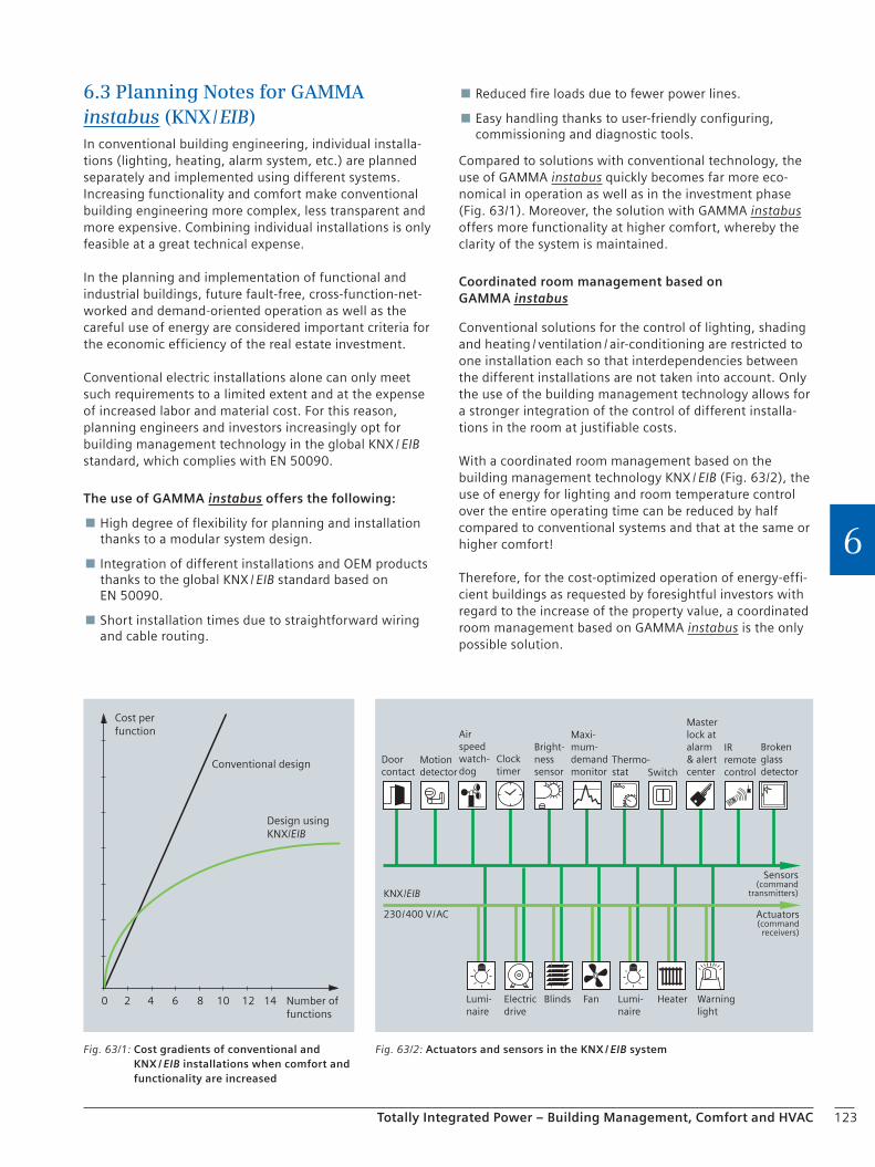
123Totally Integrated Power – Building Management, Comfort and HVAC
6
6.3 Planning Notes for GAMMA instabus (KNX / EIB)In conventional building engineering, individual installa-tions (lighting, heating, alarm system, etc.) are planned separately and implemented using different systems. Increasing functionality and comfort make conventional building engineering more complex, less transparent and more expensive. Combining individual installations is only feasible at a great technical expense.
In the planning and implementation of functional and industrial buildings, future fault-free, cross-function-net-worked and demand-oriented operation as well as the careful use of energy are considered important criteria for the economic efficiency of the real estate investment.
Conventional electric installations alone can only meet such requirements to a limited extent and at the expense of increased labor and material cost. For this reason, planning engineers and investors increasingly opt for building management technology in the global KNX / EIB standard, which complies with EN 50090.
The use of GAMMA instabus offers the following:
High degree of flexibility for planning and installation thanks to a modular system design.
Integration of different installations and OEM products thanks to the global KNX / EIB standard based on EN 50090.
Short installation times due to straightforward wiring and cable routing.
Reduced fire loads due to fewer power lines.
Easy handling thanks to user-friendly configuring, commissioning and diagnostic tools.
Compared to solutions with conventional technology, the use of GAMMA instabus quickly becomes far more eco-nomical in operation as well as in the investment phase (Fig. 63/1). Moreover, the solution with GAMMA instabus offers more functionality at higher comfort, whereby the clarity of the system is maintained.
Coordinated room management based on GAMMA instabus
Conventional solutions for the control of lighting, shading and heating / ventilation / air-conditioning are restricted to one installation each so that interdependencies between the different installations are not taken into account. Only the use of the building management technology allows for a stronger integration of the control of different installa-tions in the room at justifiable costs.
With a coordinated room management based on the building management technology KNX / EIB (Fig. 63/2), the use of energy for lighting and room temperature control over the entire operating time can be reduced by half compared to conventional systems and that at the same or higher comfort!
Therefore, for the cost-optimized operation of energy-effi-cient buildings as requested by foresightful investors with regard to the increase of the property value, a coordinated room management based on GAMMA instabus is the only possible solution.
Sensors(command
transmitters)
Actuators(command
receivers)
Doorcontact
Lumi-naire
Electricdrive
Blinds Fan Lumi-naire
Heater Warninglight
Motiondetector
Airspeedwatch-dog
Clocktimer
Bright-nesssensor
Maxi-mum-demandmonitor
Thermo-stat Switch
Masterlock atalarm& alertcenter
IRremotecontrol
Brokenglassdetector
KNX /EIB
230 / 400 V / AC
Fig. 63/2: Actuators and sensors in the KNX / EIB system
Cost perfunction
Number offunctions
Conventional design
Design usingKNX/EIB
0 2 4 6 8 10 12 14
Fig. 63/1: Cost gradients of conventional and KNX / EIB installations when comfort and functionality are increased

124
Checklist
Totally Integrated Power – Building Management, Comfort and HVAC
6
Open-loop and closed-loop control with GAMMA instabus
Project name:
Owner / developer:
Planning engineer:
Type of building use:
Degree of protection:
Functions:
c Lighting control
c Single-room control
(heating, ventilation, air-conditioning)
c Blinds and sun shield control
c Access control systems
c Time recording systems
c Daylight brightness control
c Safety lighting
c Fire alarm systems
c Burglar alarm systems
c Danger alarm systems
c Media control
c Scenario control
c Presence signaling
c Power management / control and billing
c Event logging
c Teleservice and communications
c Central controllers (e.g. ON / OFF)
c Special functions:
. . . . . . . . . . . . . . . . . . . . . . . . . . . . . . . . . . . . . . . . . . . . . . . . . . . . . . . . . . . . . . . . .
. . . . . . . . . . . . . . . . . . . . . . . . . . . . . . . . . . . . . . . . . . . . . . . . . . . . . . . . . . . . . . . . .
. . . . . . . . . . . . . . . . . . . . . . . . . . . . . . . . . . . . . . . . . . . . . . . . . . . . . . . . . . . . . . . . .
. . . . . . . . . . . . . . . . . . . . . . . . . . . . . . . . . . . . . . . . . . . . . . . . . . . . . . . . . . . . . . . . .
. . . . . . . . . . . . . . . . . . . . . . . . . . . . . . . . . . . . . . . . . . . . . . . . . . . . . . . . . . . . . . . . .
. . . . . . . . . . . . . . . . . . . . . . . . . . . . . . . . . . . . . . . . . . . . . . . . . . . . . . . . . . . . . . . . .
. . . . . . . . . . . . . . . . . . . . . . . . . . . . . . . . . . . . . . . . . . . . . . . . . . . . . . . . . . . . . . . . .
. . . . . . . . . . . . . . . . . . . . . . . . . . . . . . . . . . . . . . . . . . . . . . . . . . . . . . . . . . . . . . . . .
. . . . . . . . . . . . . . . . . . . . . . . . . . . . . . . . . . . . . . . . . . . . . . . . . . . . . . . . . . . . . . . . .
. . . . . . . . . . . . . . . . . . . . . . . . . . . . . . . . . . . . . . . . . . . . . . . . . . . . . . . . . . . . . . . . .
. . . . . . . . . . . . . . . . . . . . . . . . . . . . . . . . . . . . . . . . . . . . . . . . . . . . . . . . . . . . . . . . .
. . . . . . . . . . . . . . . . . . . . . . . . . . . . . . . . . . . . . . . . . . . . . . . . . . . . . . . . . . . . . . . . .
. . . . . . . . . . . . . . . . . . . . . . . . . . . . . . . . . . . . . . . . . . . . . . . . . . . . . . . . . . . . . . . . .
. . . . . . . . . . . . . . . . . . . . . . . . . . . . . . . . . . . . . . . . . . . . . . . . . . . . . . . . . . . . . . . . .
. . . . . . . . . . . . . . . . . . . . . . . . . . . . . . . . . . . . . . . . . . . . . . . . . . . . . . . . . . . . . . . . .
. . . . . . . . . . . . . . . . . . . . . . . . . . . . . . . . . . . . . . . . . . . . . . . . . . . . . . . . . . . . . . . . .
. . . . . . . . . . . . . . . . . . . . . . . . . . . . . . . . . . . . . . . . . . . . . . . . . . . . . . . . . . . . . . . . .
. . . . . . . . . . . . . . . . . . . . . . . . . . . . . . . . . . . . . . . . . . . . . . . . . . . . . . . . . . . . . . . . .
. . . . . . . . . . . . . . . . . . . . . . . . . . . . . . . . . . . . . . . . . . . . . . . . . . . . . . . . . . . . . . . . .
. . . . . . . . . . . . . . . . . . . . . . . . . . . . . . . . . . . . . . . . . . . . . . . . . . . . . . . . . . . . . . . . .
. . . . . . . . . . . . . . . . . . . . . . . . . . . . . . . . . . . . . . . . . . . . . . . . . . . . . . . . . . . . . . . . .
. . . . . . . . . . . . . . . . . . . . . . . . . . . . . . . . . . . . . . . . . . . . . . . . . . . . . . . . . . . . . . . . .
. . . . . . . . . . . . . . . . . . . . . . . . . . . . . . . . . . . . . . . . . . . . . . . . . . . . . . . . . . . . . . . . .
. . . . . . . . . . . . . . . . . . . . . . . . . . . . . . . . . . . . . . . . . . . . . . . . . . . . . . . . . . . . . . . . .
. . . . . . . . . . . . . . . . . . . . . . . . . . . . . . . . . . . . . . . . . . . . . . . . . . . . . . . . . . . . . . . . .
. . . . . . . . . . . . . . . . . . . . . . . . . . . . . . . . . . . . . . . . . . . . . . . . . . . . . . . . . . . . . . . . .

125Totally Integrated Power – Building Management, Comfort and HVAC
6
6.4 Power Management
Due to the increasing energy costs, saving energy becomes more and more important on every sector. At the same time, ecological goals are to be attained, e.g. the specifica-tions with regard to the reduction of emissions and green-house gases. This results first of all in the selection of energy-efficient components, but it also necessitates an ecological and economic power management.
Planning & operation
In the planning phase, the property costs are to be kept as low as possible while the operator is interested in minimiz-ing the operating costs. When planning the electrical power distribution, the basics for the power management should be established. The following aspects are to be taken into account:
Provide the required components with interfaces for measurements and sensors.
Use standardized bus systems and communication-capable devices.
Ensure expandability (e.g. expandable cable laying and installation of transformers in cabinets) to keep interruptions during operation at a minimum.
Power management system
The focus of a power management system is on the re-quest for improved transparency of energy consumption and energy quality as well as on ensuring the availability of power distribution. An all-round transparency is the basis for an optimization of energy costs and consumption. The obtained information provides a realistic basis for a cost center allocation as well as for measures to improve the energy performance. Moreover, savings are documented.
Functions of the power management system
Analysis of the energy data / energy flows with specific load curve diagrams
Visualization of the interdependencies
Detection of savings potentials, assessed minimum and maximum values
Energy measurements for accounting purposes (internal cost center allocation, external billing)
Benchmarking, internal (product line / building part) or external (property / installations with comparable use based on obtained measured values)
Visualization of the power supply with switching states and energy flows
Preparation of decisions, for example for power supply extensions
Verifiable efficiency improvements
Targeted troubleshooting via fast and detailed
information on events and faults that occur in the power distribution within the installations / building
Logging of fault and event messages (e.g. switching sequences) with a date and time stamp so that downtimes can be documented and fault processes can be traced and analyzed later using the data recorded
Compliance with purchasing contracts via the selective control of consuming devices
Automatic notification of the service personnel
Levels of the power management system
Power management is the special energy point of view of an industrial plant, a functional building, or other piece of property. The view begins with the energy import, expands to its distribution and ends at the supply to the consuming devices themselves. It comprises the following levels:
Acquisition for status and measurements
Processing
Operator control and monitoring with visualization, archiving, reports, import optimization and control of switchgear
The data acquisition level is connected to the processing level by means of field buses and the processing level communicates with the visualization system and data archive via LAN (Local Area Network) (Fig. 64/1).
The acquired status information is depicted on the status displays in the control center, thus enabling remote con-trol. Measured value readings are displayed.
Profibus
Fig. 64/1: Profibus connects the acquisition and processing level
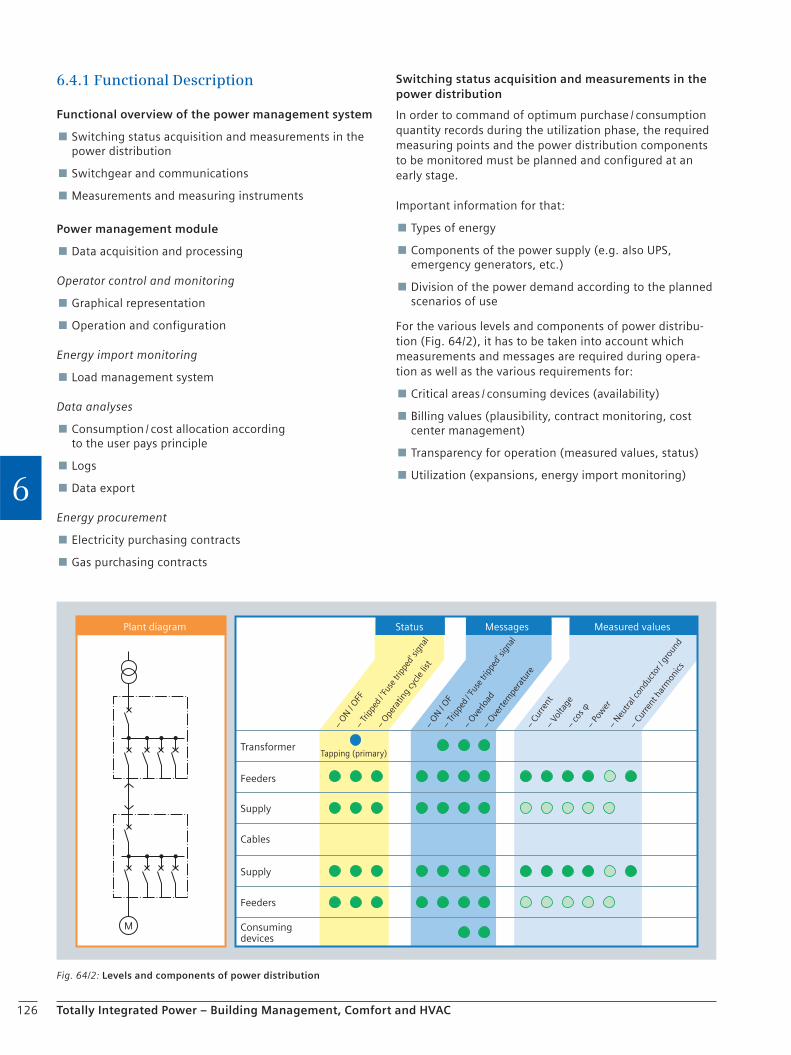
126 Totally Integrated Power – Building Management, Comfort and HVAC
6
6.4.1 Functional Description
Functional overview of the power management system
Switching status acquisition and measurements in the power distribution
Switchgear and communications
Measurements and measuring instruments
Power management module
Data acquisition and processing
Operator control and monitoring
Graphical representation
Operation and configuration
Energy import monitoring
Load management system
Data analyses
Consumption / cost allocation according to the user pays principle
Logs
Data export
Energy procurement
Electricity purchasing contracts
Gas purchasing contracts
Switching status acquisition and measurements in the power distribution
In order to command of optimum purchase / consumption quantity records during the utilization phase, the required measuring points and the power distribution components to be monitored must be planned and configured at an early stage.
Important information for that:
Types of energy
Components of the power supply (e.g. also UPS, emergency generators, etc.)
Division of the power demand according to the planned scenarios of use
For the various levels and components of power distribu-tion (Fig. 64/2), it has to be taken into account which measurements and messages are required during opera-tion as well as the various requirements for:
Critical areas / consuming devices (availability)
Billing values (plausibility, contract monitoring, cost center management)
Transparency for operation (measured values, status)
Utilization (expansions, energy import monitoring)
Fig. 64/2: Levels and components of power distribution
Plant diagram Status Messages Measured values
TransformerTapping (primary)
Supply
Feeders
Cables
Supply
Feeders
Consumingdevices
– Ove
rload
– Ove
rtem
pera
ture
– O
N / O
F
– O
N / O
FF
– Tr
ippe
d / 'F
use
tripp
ed' s
igna
l
– co
s φ–
Pow
er
– Cu
rrent
har
mon
ics
– Neu
tral c
ondu
ctor
/ gro
und
– Cu
rrent
– Vo
ltage
– Tr
ippe
d / 'F
use
tripp
ed' s
igna
l
– Ope
ratin
g cy
cle li
st
M

127
Checklist
Totally Integrated Power – Building Management, Comfort and HVAC
6
Quantitative data acquisition for status and measurements
Status information, switching commands:
Circuit-breaker-protected switchgear:
Number of circuit-breakers
Number of status information items per circuit-breaker
Total number of switching commands (for all circuit-breakers) . . . . . . . . . . . . . . . . . . . . . . . . . . . . . . . . . . . . . . . . . . . . . . . . . . . . . . . . . . . . . . . . . . .
Fuse-protected switchgear:
Number of switch-disconnectors
Number of status information items per switch-disconnector
Total number of status information items (for all circuit-breakers) . . . . . . . . . . . . . . . . . . . . . . . . . . . . . . . . . . . . . . . . . . . . . . . . . . . . . . . . . . . . . . . . . . .
Measurements:
Number of measuring points
Number of current transformers required . . . . . . . . . . . . . . . . . . . . . . . . . . . . . . . . . . . . . . . . . . . . . . . . . . . . . . . . . . . . . . . . . .
Measuring instruments:
Multi-function measuring instruments (total / measured values per device) . . . . . . . . . . . . . . . . . . . . . / . . . . . . . . . . . . . . . . . . . . . . . . . . . . . . . . . . . . . . . . . . .
Electricity meters (total / measured values per meter) . . . . . . . . . . . . . . . . . . . . . / . . . . . . . . . . . . . . . . . . . . . . . . . . . . . . . . . . . . . . . . . . .
Motor management systems (total / measured values per device) . . . . . . . . . . . . . . . . . . . . . / . . . . . . . . . . . . . . . . . . . . . . . . . . . . . . . . . . . . . . . . . . .
Circuit-breakers (total / measured values per breaker) . . . . . . . . . . . . . . . . . . . . . / . . . . . . . . . . . . . . . . . . . . . . . . . . . . . . . . . . . . . . . . . . .
Measurements for other energy types (number of measured values) . . . . . . . . . . . . . . . . . . . . . / . . . . . . . . . . . . . . . . . . . . . . . . . . . . . . . . . . . . . . . . . . .
Measurements Total number of measured values (of all measuring instruments) . . . . . . . . . . . . . . . . . . . . . / . . . . . . . . . . . . . . . . . . . . . . . . . . . . . . . . . . . . . . . . . . .
Plant diagrams:
Number of overview diagrams
Number of diagrams per energy type
Total number of diagrams (of all energy types) . . . . . . . . . . . . . . . . . . . . . . . . . . . . . . . . . . . . . . . . . . . . . . . . . . . . . . . . . . . . . . . . . . .
Energy import monitoring:
Number of monitoring items for electricity
Number of monitoring items for every other energy type
Total number of import monitoring items (of all energy types) . . . . . . . . . . . . . . . . . . . . . . . . . . . . . . . . . . . . . . . . . . . . . . . . . . . . . . . . . . . . . . . . . . .
Load management:
Number of electrical consumers
Number of consumers for every other energy type
Total number of import monitoring items (of all energy types) . . . . . . . . . . . . . . . . . . . . . . . . . . . . . . . . . . . . . . . . . . . . . . . . . . . . . . . . . . . . . . . . . . .
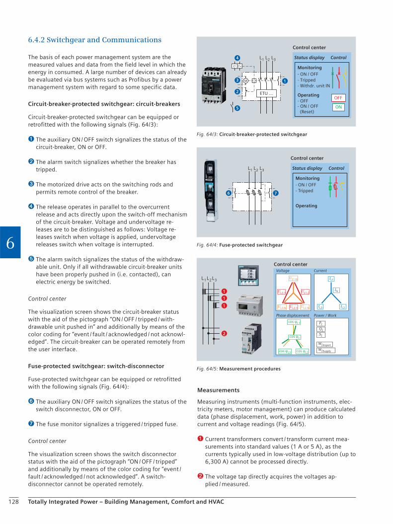
128 Totally Integrated Power – Building Management, Comfort and HVAC
6
6.4.2 Switchgear and Communications
The basis of each power management system are the measured values and data from the field level in which the energy in consumed. A large number of devices can already be evaluated via bus systems such as Profibus by a power management system with regard to some specific data.
Circuit-breaker-protected switchgear: circuit-breakers
Circuit-breaker-protected switchgear can be equipped or retrofitted with the following signals (Fig. 64/3):
➊ The auxiliary ON / OFF switch signalizes the status of the circuit-breaker, ON or OFF.
➋ The alarm switch signalizes whether the breaker has tripped.
➌ The motorized drive acts on the switching rods and permits remote control of the breaker.
➍ The release operates in parallel to the overcurrent release and acts directly upon the switch-off mechanism of the circuit-breaker. Voltage and undervoltage re-leases are to be distinguished as follows: Voltage re-leases switch when voltage is applied, undervoltage releases switch when voltage is interrupted.
➎ The alarm switch signalizes the status of the withdraw-able unit. Only if all withdrawable circuit-breaker units have been properly pushed in (i.e. contacted), can electric energy be switched.
Control center
The visualization screen shows the circuit-breaker status with the aid of the pictograph “ON / OFF / tripped / with-drawable unit pushed in” and additionally by means of the color coding for “event / fault / acknowledged / not acknowl-edged”. The circuit-breaker can be operated remotely from the user interface.
Fuse-protected switchgear: switch-disconnector
Fuse-protected switchgear can be equipped or retrofitted with the following signals (Fig. 64/4):
➏ The auxiliary ON / OFF switch signalizes the status of the switch disconnector, ON or OFF.
➐ The fuse monitor signalizes a triggered / tripped fuse.
Control center
The visualization screen shows the switch disconnector status with the aid of the pictograph “ON / OFF / tripped” and additionally by means of the color coding for “event / fault / acknowledged / not acknowledged”. A switch-disconnector cannot be operated remotely.
Measurements
Measuring instruments (multi-function instruments, elec-tricity meters, motor management) can produce calculated data (phase displacement, work, power) in addition to current and voltage readings (Fig. 64/5).
➊ Current transformers convert / transform current mea-surements into standard values (1 A or 5 A), as the currents typically used in low-voltage distribution (up to 6,300 A) cannot be processed directly.
➋ The voltage tap directly acquires the voltages ap-plied / measured.
Status display Control
Monitoring
Operating
Control center
- Tripped- ON / OFF
- ON / OFF (Reset)
- OFF
- Withdr. unit IN
L1 L2 L3
OFF
ON
U U<
M 1
2
3
4
5
ETU …
Fig. 64/3: Circuit-breaker-protected switchgear
76
Status display Control
Monitoring
Operating
Control center
- Tripped- ON / OFF
L1 L2 L3
Fig. 64/4: Fuse-protected switchgear
W∑Import
W∑Supply
Control centerVoltage Current
Phase displacement Power / Work
L1 L2 L3UL1-N
UL1-2
UL3-N UL2-NUL2-3
UL3-1
IL1
IN
IL2IL3
cos φL1
cos φ∑
cos φL3 cos φL2
S∑
Q∑
P∑
1
1
1
2
Fig. 64/5: Measurement procedures
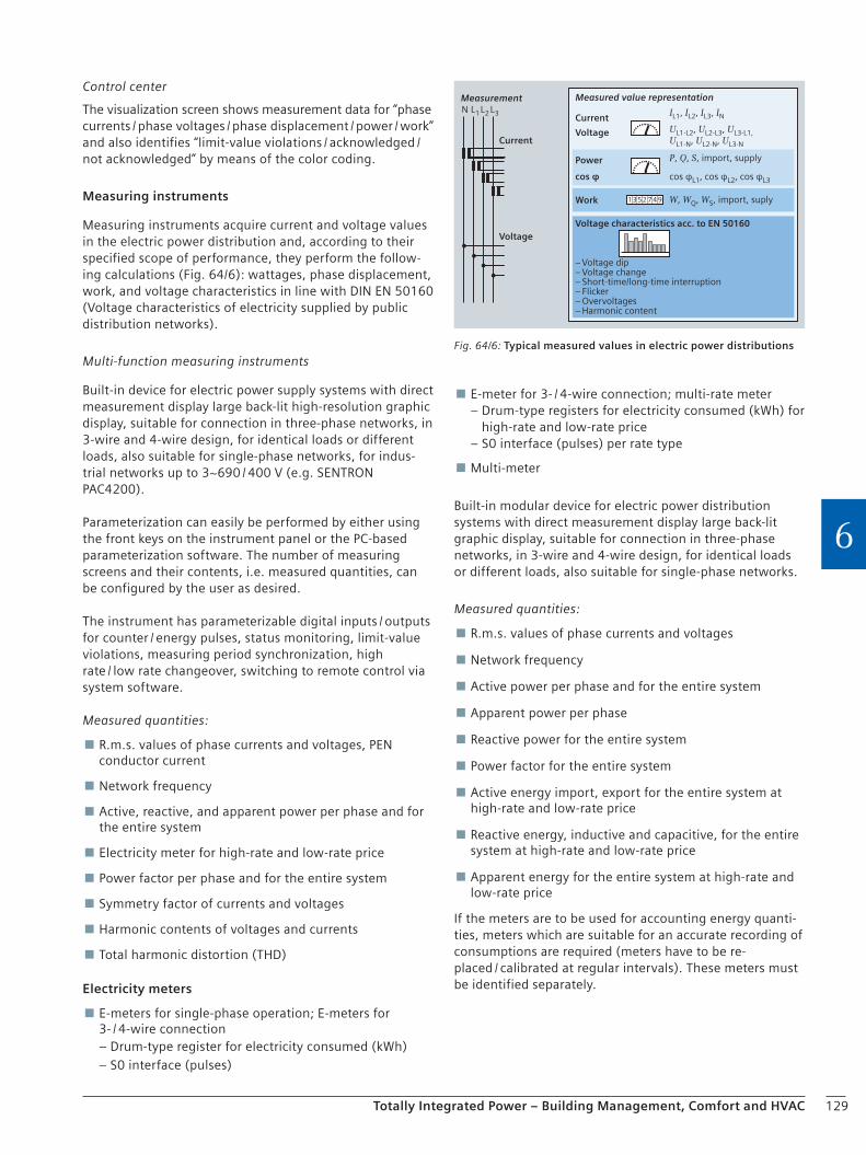
129Totally Integrated Power – Building Management, Comfort and HVAC
6
Control center
The visualization screen shows measurement data for “phase currents / phase voltages / phase displacement / power / work” and also identifies “limit-value violations / acknowledged / not acknowledged” by means of the color coding.
Measuring instruments
Measuring instruments acquire current and voltage values in the electric power distribution and, according to their specified scope of performance, they perform the follow-ing calculations (Fig. 64/6): wattages, phase displacement, work, and voltage characteristics in line with DIN EN 50160 (Voltage characteristics of electricity supplied by public distribution networks).
Multi-function measuring instruments
Built-in device for electric power supply systems with direct measurement display large back-lit high-resolution graphic display, suitable for connection in three-phase networks, in 3-wire and 4-wire design, for identical loads or different loads, also suitable for single-phase networks, for indus-trial networks up to 3~690 / 400 V (e.g. SENTRON PAC4200).
Parameterization can easily be performed by either using the front keys on the instrument panel or the PC-based parameterization software. The number of measuring screens and their contents, i.e. measured quantities, can be configured by the user as desired.
The instrument has parameterizable digital inputs / outputs for counter / energy pulses, status monitoring, limit-value violations, measuring period synchronization, high rate / low rate changeover, switching to remote control via system software.
Measured quantities:
R.m.s. values of phase currents and voltages, PEN conductor current
Network frequency
Active, reactive, and apparent power per phase and for the entire system
Electricity meter for high-rate and low-rate price
Power factor per phase and for the entire system
Symmetry factor of currents and voltages
Harmonic contents of voltages and currents
Total harmonic distortion (THD)
Electricity meters
E-meters for single-phase operation; E-meters for 3- / 4-wire connection
– Drum-type register for electricity consumed (kWh) – S0 interface (pulses)
E-meter for 3- / 4-wire connection; multi-rate meter – Drum-type registers for electricity consumed (kWh) for
high-rate and low-rate price – S0 interface (pulses) per rate type
Multi-meter
Built-in modular device for electric power distribution systems with direct measurement display large back-lit graphic display, suitable for connection in three-phase networks, in 3-wire and 4-wire design, for identical loads or different loads, also suitable for single-phase networks.
Measured quantities:
R.m.s. values of phase currents and voltages
Network frequency
Active power per phase and for the entire system
Apparent power per phase
Reactive power for the entire system
Power factor for the entire system
Active energy import, export for the entire system at high-rate and low-rate price
Reactive energy, inductive and capacitive, for the entire system at high-rate and low-rate price
Apparent energy for the entire system at high-rate and low-rate price
If the meters are to be used for accounting energy quanti-ties, meters which are suitable for an accurate recording of consumptions are required (meters have to be re-placed / calibrated at regular intervals). These meters must be identified separately.
Measured value representation
Power
cos φ
Work
Measurement
Voltage
Current
Current
Voltage
Voltage characteristics acc. to EN 50160
cos φL1, cos φL2, cos φL3
P, Q, S, import, supply
W, WQ, WS, import, suply
– Voltage dip– Voltage change– Short-time/long-time interruption– Flicker– Overvoltages– Harmonic content
IL1, IL2, IL3, IN
UL1-L2, UL2-L3, UL3-L1,UL1-N, UL2-N, UL3-N
L1 L2 L3N
1352 7 49
Fig. 64/6: Typical measured values in electric power distributions
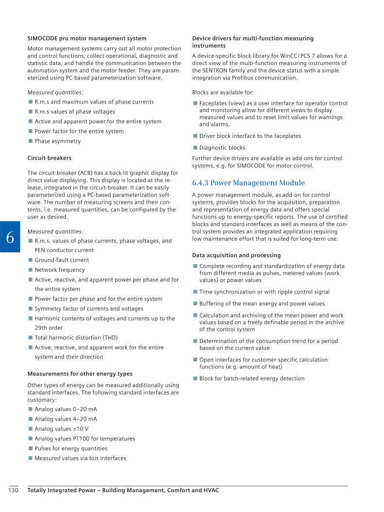
130 Totally Integrated Power – Building Management, Comfort and HVAC
6
SIMOCODE pro motor management system
Motor management systems carry out all motor protection and control functions, collect operational, diagnostic and statistic data, and handle the communication between the automation system and the motor feeder. They are param-eterized using PC-based parameterization software.
Measured quantities:
R.m.s and maximum values of phase currents
R.m.s values of phase voltages
Active and apparent power for the entire system
Power factor for the entire system
Phase asymmetry
Circuit-breakers
The circuit-breaker (ACB) has a back-lit graphic display for direct value displaying. This display is located at the re-lease, integrated in the circuit-breaker. It can be easily parameterized using a PC-based parameterization soft-ware. The number of measuring screens and their con-tents, i.e. measured quantities, can be configured by the user as desired.
Measured quantities:
R.m.s. values of phase currents, phase voltages, and
PEN conductor current
Ground-fault current
Network frequency
Active, reactive, and apparent power per phase and for
the entire system
Power factor per phase and for the entire system
Symmetry factor of currents and voltages
Harmonic contents of voltages and currents up to the
29th order
Total harmonic distortion (THD)
Active, reactive, and apparent work for the entire
system and their direction
Measurements for other energy types
Other types of energy can be measured additionally using standard interfaces. The following standard interfaces are customary:
Analog values 0–20 mA
Analog values 4–20 mA
Analog values ±10 V
Analog values PT100 for temperatures
Pulses for energy quantities
Measured values via bus interfaces
Device drivers for multi-function measuring instruments
A device-specific block library for WinCC / PCS 7 allows for a direct view of the multi-function measuring instruments of the SENTRON family and the device status with a simple integration via Profibus communication.
Blocks are available for:
Faceplates (view) as a user interface for operator control and monitoring allow for different views to display measured values and to reset limit values for warnings and alarms.
Driver block interface to the faceplates
Diagnostic blocks
Further device drivers are available as add-ons for control systems, e.g. for SIMOCODE for motor control.
6.4.3 Power Management Module
A power management module, as add-on for control systems, provides blocks for the acquisition, preparation and representation of energy data and offers special functions up to energy-specific reports. The use of certified blocks and standard interfaces as well as means of the con-trol system provides an integrated application requiring low maintenance effort that is suited for long-term use.
Data acquisition and processing
Complete recording and standardization of energy data from different media as pulses, metered values (work values) or power values
Time synchronization or with ripple control signal
Buffering of the mean energy and power values
Calculation and archiving of the mean power and work values based on a freely definable period in the archive of the control system
Determination of the consumption trend for a period based on the current value
Open interfaces for customer-specific calculation functions (e.g. amount of heat)
Block for batch-related energy detection
131Totally Integrated Power – Building Management, Comfort and HVAC
6
6.4.4 Operator Control and Monitoring
Graphic representation of plant diagrams
System information for different types of energy is visual-ized in graphics as overview or plant diagram (e.g. single-line diagram). Additional predefined, special views for devices and functions are available for that (Fig. 64/7).
Power management faceplates
A power management module provides predefined, uni-form views (faceplates) for displaying energy values, work / power values and trends for these values:
Trend view or tables for displaying the archived data
For displaying the load management data
Displaying of measured values of multi-function measuring instruments (e.g. PAC3200) or other components via device drivers
Presentation of different, general switch types via pictographs (e.g. in the single-line diagram)
Additional, predefined graphical objects which can be used in individually created graphics allow for a quick creation of views.
Graphic representation of measured values and status information
In addition to the display of the system status in the con-trol system, e.g. in a single-line diagram, and the reports, the time-based evaluation of measured values and status changes provides a basis for the assessment of the con-suming device with regard to efficiency. Load curve dia-grams are timely accurate representations with the corre-sponding selected periods for measured values, and operating cycle lists likewise represent status changes. The presentation of these archived values is done with stan-dard means of the control system.
Load curves
In this view, load curves of mean values for one or several measurement(s) with selected time ranges form the basis for the optimization of the power consumption behavior (Fig. 64/8).
Operating cycle lists
Operating cycle lists allow conclusions to be drawn about the switching behavior and causes, and permit allocations to the system behavior or load control with regard to consumption optimization (Fig. 64/9).
Monday Tuesday Wednesday FridayThursday
hours
Saturday Sunday
1000
2000
3000
4000
5000
6000
0
96
19
2
28
8
38
4
48
0
57
6
67
2
kW
Fig. 64/8: Load curves for electric power distribution
CMD switch ONCMD switch OFF
CMD shunt tripSwitch is N
Switch is OFFTripped
Withdrawable unitis pulled out
00
:15
00
:30
00
:45
01
:00
01
:15
01
:30
01
:45
02
:00
02
:15
02
:30
00
:00
Fig. 64/9: Operating cycle list for a circuit-breaker
Fig. 64/7: Graphic representation of plant diagrams

132 Totally Integrated Power – Building Management, Comfort and HVAC
6
Event log
Status changes, operator actions, limit-value violations of measurements, system events are acquired in a central standard archive and can be displayed in the respective views, filtered selectively (Fig. 64/10).
The storage in a standard archive allows for access to this data also from a control system.
Operation and configuration
For an extended ease of use, the faceplates comprise functions for
the entry of manually detected measured values,
the correction of work values in the database, and
a user-friendly configuration of the load management parameters.
Switching
As an active component to the functions for status moni-toring, general switches are provided with operating functions for switching in addition to the switching status (status, switching command, reset).
Control system
The presentation of further measurements and status information beyond the power management module can be implemented in the control system (Fig. 64/11). Access to information from the power management module is possible by using standard archives and interfaces of the control system.
Energy import monitoring
Load management systems monitor the power limits agreed within the scope of the purchasing contract and help avoid load peaks via an automatic load management in order to prevent any resulting extra costs. Costs can additionally be saved by avoiding and shifting load peaks from high-load to low-load times, i.e. by achieving evenly loaded load profiles.
The basic functionality of a load management system is automatic trend calculation based on the current consump-tion and the continuous comparison with a specified power limit (Fig. 64/12). Dependent on this result, pre-defined consuming devices are either blocked or released according to their priority, i.e. disconnected or connected, in order to keep the power limit (mean value of the power over a contractually defined period, typically 15 min for current) agreed with the power utility.
Fig. 64/10: Event log from the central standard archive
Monitoring status– ON / OFF– tripped
Operating switching– OFF– ON / OFF / Reset
Monitoring measured value– Actual-value display– Limit value display
Monitoring status– ON / OFF– Fuse tripped
OFF
ON
110 A
Power distribution Operating cycles list
Load curves
Operating cycles list
Event log
Date ident. Time ident. Site ident. Plant ident. Device ident. Function ident. Event text2000.01.14 22:59:03 Hall B Infeed Q1.0 local OFF Infeed switch switched off locally
Infeed switch switched off locally2000.01.14 23:16:24 Hall B Infeed Q1.0 local ON2000.01.20 01:12:45 Hall B Outgoing circuit T7.3 UG2 Current > 20 A 2000.01.20 01:17:13 Hall B Outgoing circuit T7.3 UG1 Current > 50 A 2000.01.15 20:59:33 Hall F Outgoing circuit Q12.1 local OFF Switch disconnector switched off locally
centralON / OFF
localON / OFF
tripped
localON / OFF
tripped
T7.3
Q12.4
Q1.0P [kW]
t
t
t
G
OFF
ON
110 A
Fig. 64/11: Operator control and monitoring in an electric power distribution system
Site x Priorities list e Consumptioncontrol
1 Consumer a
2 Consumer b
3 Consumer c
n Consumer x
rele
ase
bloc
k ON OFF
ReleaseBlocking
Feed-back
ForcedON
t150
P
M
Fig. 64/12: Energy import monitoring – priority list control

133Totally Integrated Power – Building Management, Comfort and HVAC
6
The characteristics for a load management system are the following:
Automatic and manual mode
Consumption rates management
Switching and / or signaling according to priority list for consuming devices
Rolling switching of consuming devices
Configuration to adapt to the given process conditions
Characteristic data for system or consumption behavior (e.g. hysteresis, delay, off-time, ON / OFF switching times)
Clear display and user-friendly configuration of the load management parameters directly in the faceplate
Configurable warnings / alarm messages (switching recommendation, critical states)
Analyses
A power management module provides various preconfig-ured functions for the analysis of energy data.
Exports
For the creation of predefined standard reports and the export of data, e.g. to process them in higher-level sys-tems, the data export into an Excel format is available:
Predefined macros for the export of data to Excel
Export of archived consumption data
Predefined Excel reports (in form of a table and as a bar diagram) for the evaluation of consumption data, consumption / cost allocation according to the user pays principle (rates, cost centers)
Linking of measured values via formulas
Reports
Predefined reports allow for a quick presentation of the evaluated energy data.
Evaluation of the consumption data based on specified cost center / rate reports which state where and for which product or for which cost center the respective energy consumption has accrued and which allow for benchmarking, for example.
Determination of the load duration curve based on the acquired mean power value reports which show the continuity of the use of energy and thus potential for optimizations.
Reports can be configured as:
Ad hoc protocols
Cyclic protocols for the creation of daily, weekly and monthly reports
In addition to this, reports on energy data can be gener-ated with standard means on the control system via open interfaces.
These can then also be combined to comprehensive re-ports with the other acquired data of the system (status, measurements) (Fig. 64/13).
6.4.5 Energy Procurement
Electricity purchasing contracts
Two types of purchasing contracts are currently typical for the procurement of electricity:
96-hour power metering for an annual consumption > 10,000 kWh / a and a connected load < 30 kW
¼-hour power metering > 30 kW
In quarter-hourly power metering contracts, kilowatt-per-hour rates and demand charges are agreed on and may be further subdivided (e.g. into high-rate and low-rate prices).
Gas purchasing contracts
Gas purchasing contracts are hour-based contracts, includ-ing a standing charge (€ / a) and a kilowatt-per-hour rate (€ / kWh) for energy quantities supplied.
SIEMENS
SIEMENS
SIEMENS
powerrate Reporting
Time setting
Consumption data
Start Time:End Time:Time Aggregation:Time Zone:
Cost center 1Cost center 1Cost center 11Cost center 21Cost center 30Cost center 32
Total
Consumption [kWh] Costs [€]
NoneLocal time
powerrate Reporting
Time setting
Start Time:End Time:Time Aggregation:Time Zone:
NoneLocal time
Reports
Con
sum
ptio
n [
kWh
]
powerrate Reporting
Time setting
Consumption data
Start Time:End Time:Time Aggregation:Time Zone:
NoneLocal time
Cost center 1 Cost center 11 Cost center 21
Cost center
Consumption [kWh] Costs [€]
Cost center 30 Cost center 32
020
60
120140
20 40 60 80 100 120 140 160 180
0 000,00
0 100,00
0 200,00
0 300,00
0 400,00
0 500,00
0 600,00
11,18 15,32 14,11 8,95 18,93
40
10080
05.10.2007
11:14:00 04:11:200613:16:00 04:11:2006
0.319,320.437,660,403,100.255,720.540,99
1.160,07
11,1815,3214,11 8,9518,93
40,60
11:16:00 08:11:200613:16:00 08:11:2006
19.07.2007
11:16:00 08:11:200613:16:00 08:11:2006
0
Fig. 64/13: Example of a report of status indications and measured values
134 Totally Integrated Power – Building Management, Comfort and HVAC
6
6.5 SICAM Power I&C System
6.5.1 Energy Automation for Infrastructural and Functional Buildings
Reliable power supply is essential for the functioning of our modern infrastructure. Without that, public and func-tional buildings such as sports and amusement parks, exhibition centers, stadiums, shopping centers, office buildings, hospitals, theaters, etc. would be unthinkable. We provide for an uninterruptible, highly available power supply to modern infrastructures.
Our customized solutions for the automation of power sup-ply focus on protection and power quality, station automa-tion and power management. They do not only protect your plants against possible damage but also guarantee a consistent quality of electric energy and thus the subse-quent processes in your buildings and installations. More-over, the automation of power supply ensures that unfore-seeable events in the power supply network are responded to quickly and most of all correctly to prevent possible interruptions of supply.
Reliability and demand-oriented supply with electric en-ergy can only be guaranteed because we look at energy supply as a whole. Our starting point is the supply by your power utility company or the generation in your own power plant. With suitable and correctly dimensioned medium-voltage switchgear and a reliable low-voltage power distribution, we are able to adapt your power supply exactly to your requirements – for a safe and profitable operation.
More power in the system
An integrated energy automation system comprises all systems from the supply input of the local power utility to the integration of the emergency power supply and the low-voltage level. Additionally, important signals of the building automation system can also be displayed in the same system.
The central component for information processing and system control is our SICAM automation system which is connected with the individual acquisition units (protective devices, distributed acquisition units) and the operator station via a network. On this PC, the actual user interface of the energy automation system is displayed – SIMATIC WinCC, which is standardized worldwide for operation and automation systems, serves as the visualization system.
Open for communications
For the connection of the protective devices to the energy feed-in or medium-voltage distribution, we rely on interna-tionally accepted communication standards such as IEC 60870-5-103, PROFIBUS DP, Modbus, or the new standard IEC 61850 which is based on Ethernet technology. This new standard comprises not only a generally applicable description of the communications telegrams but also precise specifications and rules for the description of the overall system for protection and automation within a station which have been included for the first time.
Apart from that, IEC 61850 also defines the rules for a direct communication of the protective devices among each other (GOOSE mechanism), also among devices from different manufacturers. Thus, actions can be taken quicker and independent of a central control directly in the field. For the connection of signals from low-voltage systems (positions of the low-voltage circuit-breakers, measured values for current, voltage, active power and reactive power, cos φ, work, but also warnings and alarms), we use customary standard components, e.g. from the SIMATIC family, which on their part are connected to the system via PROFIBUS or Modbus.
The appropriate solution
It goes without saying that your energy automation system is optimally integrated in your system environment. For interfacing to and exchange of information with other systems important for the operation of the installation, e.g. building automation, we use OPC (OLE for Process Control). Interfacing to higher-level control systems can also be implemented via an IEC 60870-5-101 or IEC 60870-5-104 protocol. To ensure defined values for failure safety and availability, parts of our systems can be designed redundantly, depending on your requirements. It goes without saying that we also provide concepts and solutions for a high degree of availability with regard to the other components used (PCs, switches, control sys-tem).
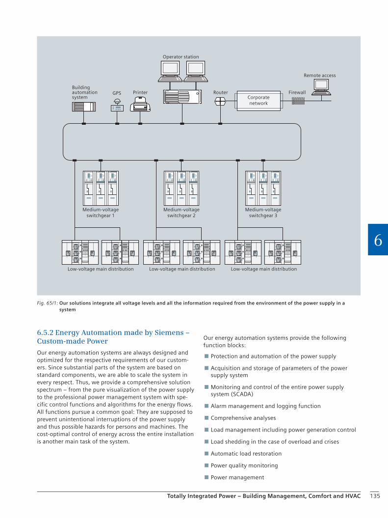
135Totally Integrated Power – Building Management, Comfort and HVAC
6
6.5.2 Energy Automation made by Siemens – Custom-made Power
Our energy automation systems are always designed and optimized for the respective requirements of our custom-ers. Since substantial parts of the system are based on standard components, we are able to scale the system in every respect. Thus, we provide a comprehensive solution spectrum – from the pure visualization of the power supply to the professional power management system with spe-cific control functions and algorithms for the energy flows. All functions pursue a common goal: They are supposed to prevent unintentional interruptions of the power supply and thus possible hazards for persons and machines. The cost-optimal control of energy across the entire installation is another main task of the system.
Our energy automation systems provide the following function blocks:
Protection and automation of the power supply
Acquisition and storage of parameters of the power supply system
Monitoring and control of the entire power supply system (SCADA)
Alarm management and logging function
Comprehensive analyses
Load management including power generation control
Load shedding in the case of overload and crises
Automatic load restoration
Power quality monitoring
Power management
Operator station
Remote access
Corporatenetwork
Printer
Medium-voltageswitchgear 1
Low-voltage main distribution
Buildingautomationsystem
Medium-voltageswitchgear 2
Medium-voltageswitchgear 3
Low-voltage main distribution Low-voltage main distribution
FirewallGPS Router
Fig. 65/1: Our solutions integrate all voltage levels and all the information required from the environment of the power supply in a system
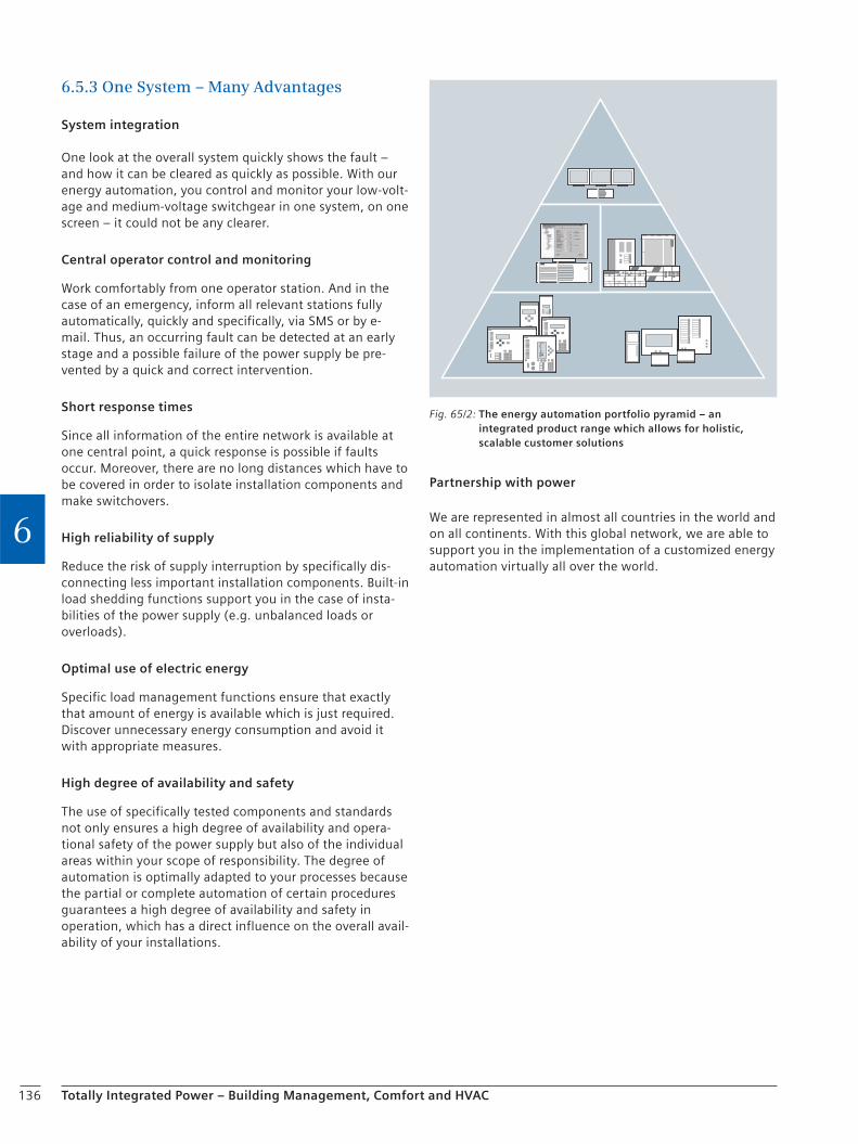
136 Totally Integrated Power – Building Management, Comfort and HVAC
6
6.5.3 One System – Many Advantages
System integration
One look at the overall system quickly shows the fault – and how it can be cleared as quickly as possible. With our energy automation, you control and monitor your low-volt-age and medium-voltage switchgear in one system, on one screen – it could not be any clearer.
Central operator control and monitoring
Work comfortably from one operator station. And in the case of an emergency, inform all relevant stations fully automatically, quickly and specifically, via SMS or by e-mail. Thus, an occurring fault can be detected at an early stage and a possible failure of the power supply be pre-vented by a quick and correct intervention.
Short response times
Since all information of the entire network is available at one central point, a quick response is possible if faults occur. Moreover, there are no long distances which have to be covered in order to isolate installation components and make switchovers.
High reliability of supply
Reduce the risk of supply interruption by specifically dis-connecting less important installation components. Built-in load shedding functions support you in the case of insta-bilities of the power supply (e.g. unbalanced loads or overloads).
Optimal use of electric energy
Specific load management functions ensure that exactly that amount of energy is available which is just required. Discover unnecessary energy consumption and avoid it with appropriate measures.
High degree of availability and safety
The use of specifically tested components and standards not only ensures a high degree of availability and opera-tional safety of the power supply but also of the individual areas within your scope of responsibility. The degree of automation is optimally adapted to your processes because the partial or complete automation of certain procedures guarantees a high degree of availability and safety in operation, which has a direct influence on the overall avail-ability of your installations.
Partnership with power
We are represented in almost all countries in the world and on all continents. With this global network, we are able to support you in the implementation of a customized energy automation virtually all over the world.
Fig. 65/2: The energy automation portfolio pyramid – an integrated product range which allows for holistic, scalable customer solutions

137
Checklist
Totally Integrated Power – Building Management, Comfort and HVAC
6
Energy automation system
Project data:
c Name
c End customer
c Planning engineer / EPC / consultant
c Installation type
c City / Country
c New project
c Expansion
Existing documentation:
c Specification / concept
c Network study
c Single-line
c Topology plan
Systems to be connected or possibly already existing (manufacturer):
c Protection
c Substation automation
c Power quality
c Control center
c Process automation
c Other
Existing customer generation (type and power):
Topology:
c Number of substations
c Number of voltage levels
c Number of transformers (feed-in / distribution transformers)
c Number of supply panels
c Number of feeder panels
c Number of coupling panels
c Number of signals / IOs (digital / analog)
c . . . . . . . . . . . . . . . . . . . . . . . . . . . . . . . . . . . . . . . .
Required control system functions:
c Alarm management
c Archiving
c Monitoring and control (SCADA)
c Power management
c Cost center allocation
c Load shedding
c Load management
c Switching sequences
c Fault record processing
c Synchronization
c Transformer tap control
c Switch interlockings
c . . . . . . . . . . . . . . . . . . . . . . . . . . . . . . . . . . . . . . . .
Preferred system:
c Software solution (PC-based)
c Hardware solution (subrack-based)
c . . . . . . . . . . . . . . . . . . . . . . . . . . . . . . . . . . . . . . . .
Required communication protocols:
c IEC 61850 Client
c IEC 60870 101 (Master / Slave)
c IEC 60870 103 Master
c IEC 60870 104 (Master / Slave)
c DNP 3.0 (Master / Slave) (over IP)
c Modbus
c OPC (Server / Client)
c PROFIBUS DP
c SNMP
c . . . . . . . . . . . . . . . . . . . . . . . . . . . . . . . . . . . . . . . .
Required interfaces / data transmission rates (number and type):
c Distance bay devices – control system . . . . . . . . . . . m
c Electrical / optical waveguide
138
Checklist
Totally Integrated Power – Building Management, Comfort and HVAC
6
c Ethernet
c Radio
c Serial
c . . . . . . . . . . . . . . . . . . . . . . . . . . . . . . . . . . . . . . . .
Visualization system – Human Machine Interface (HMI):
c Number of control centers
c Number of local workplaces
c Option for laptop connection
c Number of monitors per workplace
c . . . . . . . . . . . . . . . . . . . . . . . . . . . . . . . . . . . . . . . .
Other requirements:
c Redundancy
c Firewall
c Security
c Explosion-proof area
c Special environmental conditions (e.g. temperature / humidity)
c . . . . . . . . . . . . . . . . . . . . . . . . . . . . . . . . . . . . . . . .
Schedule / dates:
c Invitation to tender / concept
c Submission of quotation
c Commissioning
c Start of production / use
c . . . . . . . . . . . . . . . . . . . . . . . . . . . . . . . . . . . . . . . .
Contact person:
c Name
c Company / department
c Address
c Telephone
c Mobile
c E-mail
c . . . . . . . . . . . . . . . . . . . . . . . . . . . . . . . . . . . . . . . .
. . . . . . . . . . . . . . . . . . . . . . . . . . . . . . . . . . . . . . . . . . . . . . . . . . . . . . . . . . . . . . . . .
. . . . . . . . . . . . . . . . . . . . . . . . . . . . . . . . . . . . . . . . . . . . . . . . . . . . . . . . . . . . . . . . .
. . . . . . . . . . . . . . . . . . . . . . . . . . . . . . . . . . . . . . . . . . . . . . . . . . . . . . . . . . . . . . . . .
. . . . . . . . . . . . . . . . . . . . . . . . . . . . . . . . . . . . . . . . . . . . . . . . . . . . . . . . . . . . . . . . .
. . . . . . . . . . . . . . . . . . . . . . . . . . . . . . . . . . . . . . . . . . . . . . . . . . . . . . . . . . . . . . . . .
. . . . . . . . . . . . . . . . . . . . . . . . . . . . . . . . . . . . . . . . . . . . . . . . . . . . . . . . . . . . . . . . .
. . . . . . . . . . . . . . . . . . . . . . . . . . . . . . . . . . . . . . . . . . . . . . . . . . . . . . . . . . . . . . . . .
. . . . . . . . . . . . . . . . . . . . . . . . . . . . . . . . . . . . . . . . . . . . . . . . . . . . . . . . . . . . . . . . .
. . . . . . . . . . . . . . . . . . . . . . . . . . . . . . . . . . . . . . . . . . . . . . . . . . . . . . . . . . . . . . . . .
. . . . . . . . . . . . . . . . . . . . . . . . . . . . . . . . . . . . . . . . . . . . . . . . . . . . . . . . . . . . . . . . .
. . . . . . . . . . . . . . . . . . . . . . . . . . . . . . . . . . . . . . . . . . . . . . . . . . . . . . . . . . . . . . . . .
. . . . . . . . . . . . . . . . . . . . . . . . . . . . . . . . . . . . . . . . . . . . . . . . . . . . . . . . . . . . . . . . .
. . . . . . . . . . . . . . . . . . . . . . . . . . . . . . . . . . . . . . . . . . . . . . . . . . . . . . . . . . . . . . . . .
. . . . . . . . . . . . . . . . . . . . . . . . . . . . . . . . . . . . . . . . . . . . . . . . . . . . . . . . . . . . . . . . .
. . . . . . . . . . . . . . . . . . . . . . . . . . . . . . . . . . . . . . . . . . . . . . . . . . . . . . . . . . . . . . . . .
. . . . . . . . . . . . . . . . . . . . . . . . . . . . . . . . . . . . . . . . . . . . . . . . . . . . . . . . . . . . . . . . .
. . . . . . . . . . . . . . . . . . . . . . . . . . . . . . . . . . . . . . . . . . . . . . . . . . . . . . . . . . . . . . . . .
. . . . . . . . . . . . . . . . . . . . . . . . . . . . . . . . . . . . . . . . . . . . . . . . . . . . . . . . . . . . . . . . .
. . . . . . . . . . . . . . . . . . . . . . . . . . . . . . . . . . . . . . . . . . . . . . . . . . . . . . . . . . . . . . . . .
. . . . . . . . . . . . . . . . . . . . . . . . . . . . . . . . . . . . . . . . . . . . . . . . . . . . . . . . . . . . . . . . .
. . . . . . . . . . . . . . . . . . . . . . . . . . . . . . . . . . . . . . . . . . . . . . . . . . . . . . . . . . . . . . . . .
. . . . . . . . . . . . . . . . . . . . . . . . . . . . . . . . . . . . . . . . . . . . . . . . . . . . . . . . . . . . . . . . .
. . . . . . . . . . . . . . . . . . . . . . . . . . . . . . . . . . . . . . . . . . . . . . . . . . . . . . . . . . . . . . . . .
. . . . . . . . . . . . . . . . . . . . . . . . . . . . . . . . . . . . . . . . . . . . . . . . . . . . . . . . . . . . . . . . .
. . . . . . . . . . . . . . . . . . . . . . . . . . . . . . . . . . . . . . . . . . . . . . . . . . . . . . . . . . . . . . . . .
. . . . . . . . . . . . . . . . . . . . . . . . . . . . . . . . . . . . . . . . . . . . . . . . . . . . . . . . . . . . . . . . .
. . . . . . . . . . . . . . . . . . . . . . . . . . . . . . . . . . . . . . . . . . . . . . . . . . . . . . . . . . . . . . . . .
. . . . . . . . . . . . . . . . . . . . . . . . . . . . . . . . . . . . . . . . . . . . . . . . . . . . . . . . . . . . . . . . .
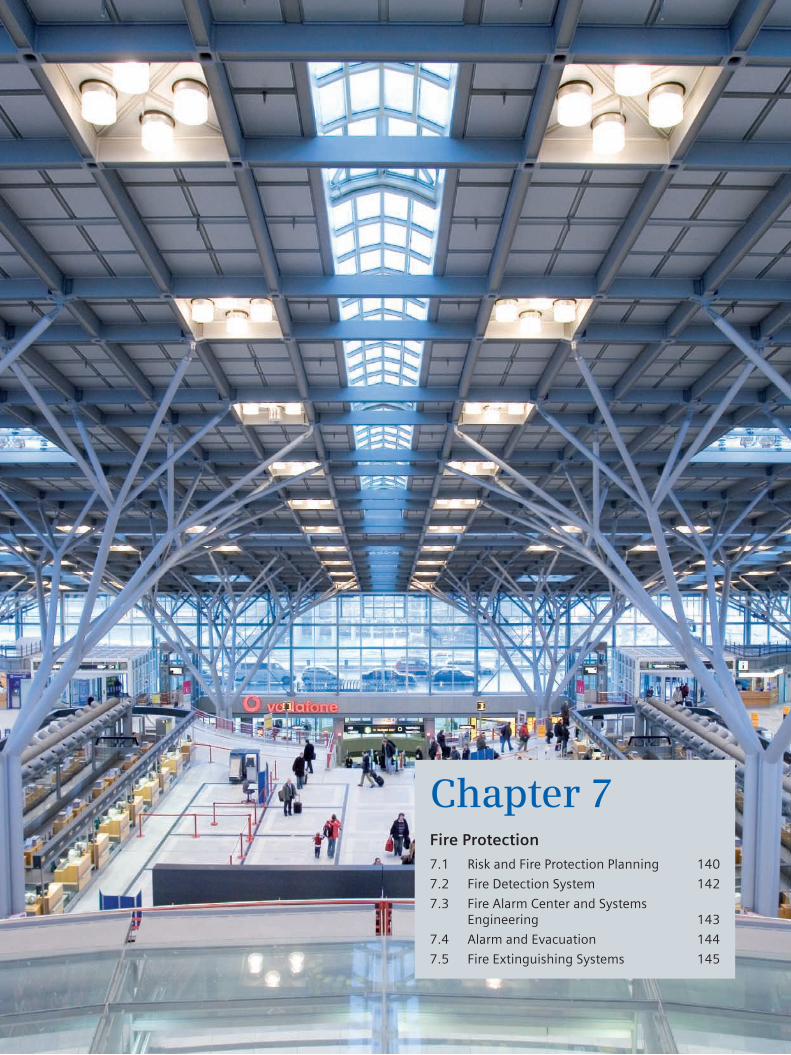
Chapter 7Fire Protection
7.1 Risk and Fire Protection Planning 140
7.2 Fire Detection System 142
7.3 Fire Alarm Center and Systems Engineering 143
7.4 Alarm and Evacuation 144
7.5 Fire Extinguishing Systems 145

140 Totally Integrated Power – Fire Protection
7
7 Fire ProtectionFor effective fire protection, two conditions have to be fulfilled: Firstly, the fire must be detected quickly and clearly and signaled. And secondly, correct measures must be implemented as quickly as possible. This is the only way to avoid direct fire and consequential damage or at least to keep this to a minimum.
7.1 Risk and Fire Protection Planning
The term 'risk' expresses the degree of danger. The risk factor is received by multiplying the probability of occur-rence of an event with its impacts. The probability of occurrence has to be determined for each room individu-ally. The term 'impacts' combines all expectable conse-quences of the event. Therefore, all consequences – also those outside the room – have to be detected and the individual results be added to calculate the impacts. The risk is then calculated by multiplying the impacts with the probability of occurrence. A possible procedure is shown in Table 71/1. The calculated risk levels (R = P × I) are listed in Table 71/2.
Fire protection planning is based on a risk analysis as described above. The task definition for this is to find out how the defined protection goal can be attained with an assignment of means as economical as possible. The result of this work is the fire protection concept.
Among other things, the following factors have to be taken into account:
Physical principles (fire development, smoke, flame propagation, etc.)
Building conditions (basic structure, geometry, escape routes, ventilations, infrastructure such as energy channels, installations, etc.)
Boundary conditions of the building operator (fixed and variable fire loads, processes, personnel organization, etc.)
Table 71/1: Table for determining the risk level
Probability of occurrence (P)
Impacts (I)
1 = very likely 1 = few or none Hazardous to life and/or material assets (tangible or intangible)
2 = unlikely 2 = medium
3 = likely 3 = high
4 = occasionally 4 = very high
5 = frequently 5 = existence-threatening
Risk = probability of occurrence × impacts
Table 71/2: Risk levels and urgency
Risk level (R) DescriptionPriority
level
Urgency of protective measures
18, 20, 25 Highest risk 1 Immediately
8, 9, 10, 12, 15 High risk 2 Short-term
4, 5, 6 Medium risk 3 Medium-term
2, 3 Low risk 4 Long-term
1 Negligible risk 5 Not required

141Totally Integrated Power – Fire Protection
7
Checklist
Risk minimization in fire protection
Flammable gases, liquids and materials have to be stored at safe places.
Larger quantities of chemicals have to be stored in such a way that as few chemical reactions as possible take place. Acids and bases, for example, have to be stored separately.
Areas with dangerous goods have to be provided with corresponding information and no-smoking signs.
Fire loads not required, e.g. flammable materials which are not immediately required, are not to be stored at the workplace but at a safe place.
The waste management is to be designed such that no flammable waste at all gathers outside the areas intended for it.
Heaters, fan heaters, etc. are a particular fire risk. It has to be ensured that the safe distances to flammable materials are kept. Therefore, portable or not permanently mounted fan heaters should be abandoned, if possible.
Specifically identified smoking areas with ashtrays etc. allow for a disciplined handling of tobaccos. This prevents an uncontrolled disposal of cigarette stubs and matches.
Up to 40% of the fires are caused by arson. With an access control system, the access to critical areas can be controlled and thus the risk of arson, in particular by strangers, be reduced.
Most of the cases of electric firing occur while the device is in standby mode. Therefore, instruments which are not required should be switched off with the power switch whenever possible.
Cable extensions and power strips have to be avoided wherever possible.
Electrical appliances and the electric wiring have to be checked periodically by a specialist.
Fuses have to comply with the device requirements and installations.
The smoke and flame propagation between rooms and fire areas have to be prevented with suitable measures.
Fire doors either have to be kept closed or it must be possible to close them automatically in case of a fire via automatic closing mechanisms. The functional reliability of the closing mechanisms is to be ensured with periodical, preventive maintenance.
In the area of fire doors, no objects at all must be deposited. Moreover, fire doors have to be signed accordingly.
Emergency exits preferably have to lead directly to safe streets/places. Emergency exits to enclosed inner courtyards are not permissible, for example, since it would not be possible to increase the distance to the building, if necessary.
Emergency exits have to be well signed and lit also in case of an emergency.
It has to be ensured that emergency exits are not blocked with furniture, wheelbarrows, etc.
Emergency exits have to be safely walkable. This includes the state of the floors (no loose carpets, smooth surfaces, etc.) as well as the danger of falling due to obstacles (electric cables or wet floors).
Doors in emergency exits have to open up to the outside and it must always be possible to open them from the inside. In case of misuse, a key box with a glass to be broken or a door alarm (alarm goes off as soon as the door is opened) might help. However, this requires clear, easily understandable information signs.
It has been proved that the quickest possible fire alarm is effected by an automatic fire detection system. Its operability is to be ensured via periodical, preventive maintenance.
A fire detection system has to alarm the fire department either directly or via an alarm receiving station.
The personnel is to be trained such that a quick, correct alerting and an ordered evacuation of the building is ensured.
Hand fire extinguishers and fire blankets allow for a quick extinguishing of emerging fires and therefore have to be positioned at well visible places in sufficient quantities.
The personnel has to be imparted the basics of fire-fighting and trained the use of fire-fighting equipment for manual fire-fighting (hand fire extinguisher, fire blanket, etc.).
If the use of the building has been changed, the fire precautions have to be reviewed and adapted, if necessary.
The risk analysis and fire protection planning have to be kept and continuously adapted to the changes.
Fire insurance companies often give valuable hints how to improve the fire protection for real property.

142 Totally Integrated Power – Fire Protection
7
7.2 Fire Detection System
A fire detection system consists of the individual detectors and the fire alarm center. The components are to ensure quick and spurious-safe alerting. To this end, the individual components have to be optimally matched.
Intelligent, high-speed evaluation models of advanced fire detection systems such as the SINTESO detectors with ASA (Advanced Signal Analysis) technology enable smoke and fire to be detected immediately and spurious-safely, no matter how difficult the environmental conditions. These detectors can be programmed optimally for the conditions at the location of use.
Point-type smoke detectors
Point-type smoke detectors are installed at the ceiling or at the place at which the propagation and accumulation of the fire parameter smoke is to be expected. Point-type multi-sensor smoke detectors which detect smoke and heat simultaneously are to be placed like point-type smoke detectors.
Point-type smoke detectors may normally be used up to a room height of 12 m. With the room height increasing, the smoke density at the ceiling decreases because the given quantity of smoke is distributed in a larger air volume. Moreover, the cooling smoke is no longer able to permeate the heat cushion at the ceiling of high rooms.
The following conclusions can be drawn from that: With the room height increasing,
the response sensitivity of the fire alarm system has to be higher or an increasingly larger initial fire is required for alarm release.
the monitored area per smoke detector may be increased.
the smoke of smoldering fires decreasingly reaches the ceiling and thus the detectors.
the smoke detectors have to be detached ever further from the ceiling.
Point-type heat detectors
In contrast to smoke detectors, heat detectors are to be installed at the highest point of the ceiling. In order to prevent false alarms and nevertheless ensure a justifiable response behavior, the static response temperature of heat detectors has to range between 10 °C and 35 °C above the highest temperature which may occur due to natural or operational influences in the area surrounding the detector.
Class A1 heat detectors may normally be used up to a room height of 7.5 m. The temperature increase at the ceiling directly over the fire location decreases approximately quadratically with the room height increasing. This means that with the room height increasing, the response sensi-tivity of the heat detectors has to be higher or an increas-ingly larger fire is required for alarm release.
The monitored area depends on the size of the room to be monitored and the slope of the ceiling. In the case of sloping ceilings, the heat along the ceiling slope increases up to the highest point. This results in a heat concentra-tion in the roof ridge. This is why in the case of sloping roofs, the basic monitored area and the detector distance may be increased.
Linear smoke detectors
A linear smoke detector consists of a transmitter and a receiver for infrared light and works similar to a light barrier. It is installed below the ceiling on the wall. There must be a permanent, interference-free line of sight be-tween the detector and reflector. The monitoring beam must not be interrupted by moving objects such as over-head traveling cranes, ladders, suspended advertising media or other movable objects.
The detector has to be installed permanently and unmov-able. Here, it also has to be kept in mind that flexible wall constructions are unsuitable because a too large deflection of the monitoring beam prevents reliable detection. Con-crete and brick walls fulfill these requirements. Wood and steel constructions are mostly unsuitable because changes of temperature and humidity, wind or snow pressure can influence such constructions.
Heat cushions below the ceiling can prevent the rising smoke from reaching the ceiling. The linear smoke detec-tor therefore has to be installed below a heat cushion to be expected. In the case of room heights above 12 m, the distance to the ceiling should range between 60 and 120 cm.
To ensure that smoldering fires or smaller fires with low fire thermal can also be detected in high rooms, a second or possibly a third detector has to be installed at the as-sumed height of the smoke propagation of the smoldering fire. This level differentiation becomes important in the case of rooms with a height of 6 m or higher.
Detectors of the lower monitoring level should be arranged in an offset pattern compared to the top monitoring level.

143Totally Integrated Power – Fire Protection
7
7.3 Fire Alarm Center and Systems EngineeringThe fire alarm center evaluates the signals from the periph-eral devices, controls the alarm and fire control system and is furthermore the point of interaction between persons and the system. The term 'systems engineering' compasses all components of a fire alarm system including their communication, i.e. the networking of the field elements (sensors and actuators) with the fire alarm center and possibly several fire alarm centers among each other as well as with higher-level management systems (Fig. 73/1).
A modern fire alarm center provides the following functional features:
Simple and safe system operation
Flexible system design with regard to size and structure
Free adaptation of the central organization to changing customer requirements
Freely programmable control outputs for the use of fire control systems
Event memory which stores hundreds of events, sorted according to information classes, and provides them when required
Integrated emergency operation functions so that in the event of the failure of a signal processing unit, a reliable fire alarm can still be guaranteed
Real-time clock with date and automatic change-over to summer and winter time
The functional scope of each system for a specific case has to be clarified in advance.
Power supply
The power supply provides the required energy for the fire alarm system. In accordance with EN 54, two independent power sources have to guarantee the power supply for the fire alarm center in parallel stand-by mode. Both power sources have to be dimensioned such that in the event of the failure of one source, the operation of the system and the alarm installations can be maintained for a certain period of time. The following has to be taken into account for that:
One of the two power sources has to be a permanent mains supply, the other one a battery or similar source.
Parallel operation is required in which the correspondingly dimensioned charger supplies the fire alarm system and simultaneously charges the batteries connected in parallel.
The emergency power supply of the fire alarm system has to be effected via a separately secured feeder line.
Devices which are not part of the fire alarm system must not be connected to the power supply of the system.
The battery capacity has to be dimensioned such that the unrestricted operation of the fire alarm system is possible during the requested emergency operation time and that the alarm devices can be supplied for at least another 30 minutes after the end of the emergency operation time.
The use of monitored remote power supply units is permitted.
Signals from the remote power supply units are to be displayed in the control center like fault indications.
With regard to the assumption of interference signals and troubleshooting, emergency power transitory periods in accordance with Table 73/1 are recommended.
Table 73/1: Emergency operation time demanded by EN 54
Emergency power criteria Emergency operation time [h]
Without interference signal transmission to a permanently manned control center (for bridging weekends)
72
With interference signal transmission to an internal or external, permanently manned control center
30
With interference signal transmission to a permanently manned control center, secured mains connection (e.g. emergency-power diesel generator for 24/7 operation)
4
Fig. 73/1: Fire alarm center and systems engineering
Fire alarm center (CPU)
Lines interface
Control interface
Commissioning Maintenance
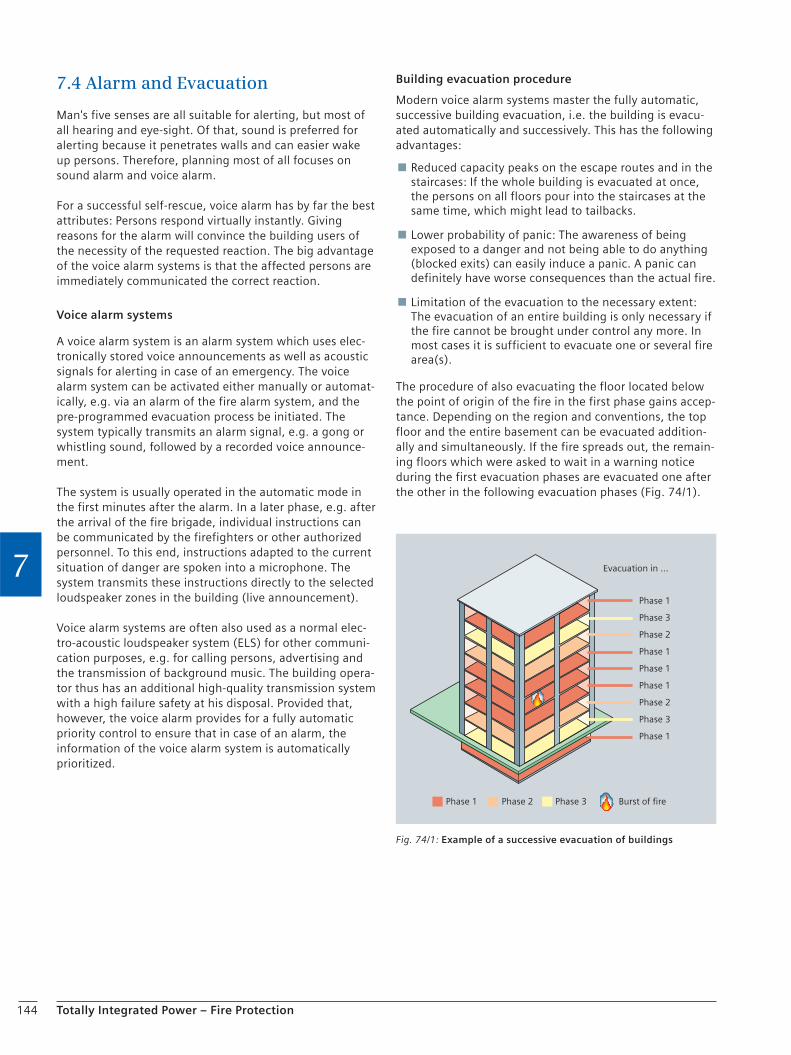
144 Totally Integrated Power – Fire Protection
7
7.4 Alarm and Evacuation
Man's five senses are all suitable for alerting, but most of all hearing and eye-sight. Of that, sound is preferred for alerting because it penetrates walls and can easier wake up persons. Therefore, planning most of all focuses on sound alarm and voice alarm.
For a successful self-rescue, voice alarm has by far the best attributes: Persons respond virtually instantly. Giving reasons for the alarm will convince the building users of the necessity of the requested reaction. The big advantage of the voice alarm systems is that the affected persons are immediately communicated the correct reaction.
Voice alarm systems
A voice alarm system is an alarm system which uses elec-tronically stored voice announcements as well as acoustic signals for alerting in case of an emergency. The voice alarm system can be activated either manually or automat-ically, e.g. via an alarm of the fire alarm system, and the pre-programmed evacuation process be initiated. The system typically transmits an alarm signal, e.g. a gong or whistling sound, followed by a recorded voice announce-ment.
The system is usually operated in the automatic mode in the first minutes after the alarm. In a later phase, e.g. after the arrival of the fire brigade, individual instructions can be communicated by the firefighters or other authorized personnel. To this end, instructions adapted to the current situation of danger are spoken into a microphone. The system transmits these instructions directly to the selected loudspeaker zones in the building (live announcement).
Voice alarm systems are often also used as a normal elec-tro-acoustic loudspeaker system (ELS) for other communi-cation purposes, e.g. for calling persons, advertising and the transmission of background music. The building opera-tor thus has an additional high-quality transmission system with a high failure safety at his disposal. Provided that, however, the voice alarm provides for a fully automatic priority control to ensure that in case of an alarm, the information of the voice alarm system is automatically prioritized.
Building evacuation procedure
Modern voice alarm systems master the fully automatic, successive building evacuation, i.e. the building is evacu-ated automatically and successively. This has the following advantages:
Reduced capacity peaks on the escape routes and in the staircases: If the whole building is evacuated at once, the persons on all floors pour into the staircases at the same time, which might lead to tailbacks.
Lower probability of panic: The awareness of being exposed to a danger and not being able to do anything (blocked exits) can easily induce a panic. A panic can definitely have worse consequences than the actual fire.
Limitation of the evacuation to the necessary extent: The evacuation of an entire building is only necessary if the fire cannot be brought under control any more. In most cases it is sufficient to evacuate one or several fire area(s).
The procedure of also evacuating the floor located below the point of origin of the fire in the first phase gains accep-tance. Depending on the region and conventions, the top floor and the entire basement can be evacuated addition-ally and simultaneously. If the fire spreads out, the remain-ing floors which were asked to wait in a warning notice during the first evacuation phases are evacuated one after the other in the following evacuation phases (Fig. 74/1).
Fig. 74/1: Example of a successive evacuation of buildings
Phase 1
Phase 3
Phase 2
Phase 1
Phase 1
Phase 1
Phase 2
Phase 3
Phase 1
Phase 1 Phase 2 Phase 3 Burst of fire
Evacuation in ...
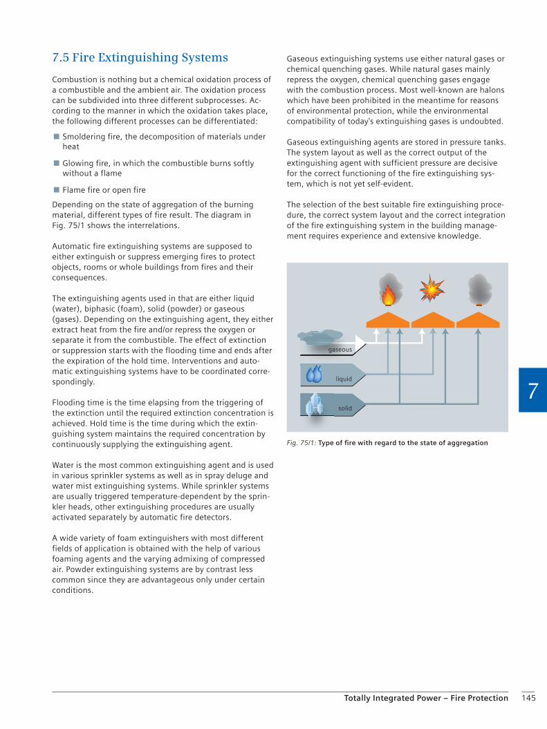
145Totally Integrated Power – Fire Protection
7
7.5 Fire Extinguishing Systems
Combustion is nothing but a chemical oxidation process of a combustible and the ambient air. The oxidation process can be subdivided into three different subprocesses. Ac-cording to the manner in which the oxidation takes place, the following different processes can be differentiated:
Smoldering fire, the decomposition of materials under heat
Glowing fire, in which the combustible burns softly without a flame
Flame fire or open fire
Depending on the state of aggregation of the burning material, different types of fire result. The diagram in Fig. 75/1 shows the interrelations.
Automatic fire extinguishing systems are supposed to either extinguish or suppress emerging fires to protect objects, rooms or whole buildings from fires and their consequences.
The extinguishing agents used in that are either liquid (water), biphasic (foam), solid (powder) or gaseous (gases). Depending on the extinguishing agent, they either extract heat from the fire and/or repress the oxygen or separate it from the combustible. The effect of extinction or suppression starts with the flooding time and ends after the expiration of the hold time. Interventions and auto-matic extinguishing systems have to be coordinated corre-spondingly.
Flooding time is the time elapsing from the triggering of the extinction until the required extinction concentration is achieved. Hold time is the time during which the extin-guishing system maintains the required concentration by continuously supplying the extinguishing agent.
Water is the most common extinguishing agent and is used in various sprinkler systems as well as in spray deluge and water mist extinguishing systems. While sprinkler systems are usually triggered temperature-dependent by the sprin-kler heads, other extinguishing procedures are usually activated separately by automatic fire detectors.
A wide variety of foam extinguishers with most different fields of application is obtained with the help of various foaming agents and the varying admixing of compressed air. Powder extinguishing systems are by contrast less common since they are advantageous only under certain conditions.
Gaseous extinguishing systems use either natural gases or chemical quenching gases. While natural gases mainly repress the oxygen, chemical quenching gases engage with the combustion process. Most well-known are halons which have been prohibited in the meantime for reasons of environmental protection, while the environmental compatibility of today's extinguishing gases is undoubted.
Gaseous extinguishing agents are stored in pressure tanks. The system layout as well as the correct output of the extinguishing agent with sufficient pressure are decisive for the correct functioning of the fire extinguishing sys-tem, which is not yet self-evident.
The selection of the best suitable fire extinguishing proce-dure, the correct system layout and the correct integration of the fire extinguishing system in the building manage-ment requires experience and extensive knowledge.
gaseous
liquid
solid
Fig. 75/1: Type of fi re with regard to the state of aggregation

146 Totally Integrated Power – Fire Protection
7
Chapter 8 Security Systems
8.1 Robbery and Burglar Alarm Systems (RAS and BAS) 148
8.2 Video Surveillance Systems (CCTV) 150
8.3 Access Control 150
8.4 Danger Management System 151

148 Totally Integrated Power – Security Systems
8
There are various risk potentials – environmental catastro-phes, fire, robbery, burglary and spying, theft and vandal-ism, terrorism and extremism. These risks have to be identified and analyzed and the appropriate security con-cepts have to be developed. Prevention, intervention and rescue measures are to be implemented for many of these risks within the scope of the legal standards and guide-lines.
Mechanical protection equipment which is reasonably matched ranks first in security systems. It can oppose a certain resistance to the intruder and possibly prevent a burglary. It is therefore an essential prerequisite for an effective protection against burglary.
In contrast, burglar alarm systems (BAS) are only able to signal. They do not prevent burglary but can act as a deterrent. Due to the signaling effect, the burglar's risk of being discovered is considerably increased.
The best thing is to reasonably combine the mechanical protection equipment with electronic monitoring. As a rule, the BAS should be expanded in such a way that also a hold-up alarm can be triggered.
8.1 Robbery and Burglar Alarm Systems (RAS and BAS)
Fields of application for burglar alarm systems
Hold-up protection Hold-up / emergency call solutions for persons and areas with a high risk potential
Exterior shell and opening surveillance Comprehensive surveillance of the building's exterior shell for closure, openings or break-through
Room surveillance Reliable detection of movements in protected areas
Object protection Selective monitoring of individual objects or valuables containers
Alarm and transmission On-site alarm and fast alarm transmission to the service center or directly to the police
Perimeter surveillance / protection Complete surveillance of the outdoor area of the premises and spacious areas
The appropriate degree of protection
Burglar alarm systems (BAS) are subdivided into different security levels according to the risk. The standards provide for a total of four levels. Level 1 is below the police require-ments and is therefore not recommended.
For the protection of persons and smaller residential prop-erties, a class A or level 2 RAS / BAS with a medium protec-tion against overcoming and a medium response sensitiv-ity is sufficient.
A class B or level 3 RAS / BAS with a high protection against overcoming and a medium response sensitivity is used when persons or residential property with an increased risk potential or smaller commercial properties or public prop-erties are to be monitored.
For the protection of persons, commercial or public proper-ties and residential properties with a high risk potential, class C or level 4 RAS / BAS with a very high protection against overcoming and an increased response sensitivity should be selected.
Important guidelines for robbery and burglar alarm systems
Comprehensive information on the relevant guidelines – standards, VdS guidelines (Verband der Schadensversich-erer e. V. – German association of indemnity insurers), rules for the prevention of accidents, guidelines for rob-bery and burglar alarm systems with connection to the police, etc. – can be obtained from the Siemens brochure with the order no. E10003-A38-E19.
8 Security Systems

149Totally Integrated Power – Security Systems
8
Checklist
Determine the type of surveillance most suitable for your object:
Exterior shell surveillance in which all security- –relevant openings such as doors and windows in the exterior shell of the object to be protected are monitored. Trap surveillance in which predominantly those areas –are monitored which an intruder will enter with the utmost probability. A combination of both types of monitoring. –
The planning and installation of an RAS / BAS should preferably be implemented in such a way that in case of a burglar attempt, the alarm release already takes place before the burglars have overcome the mechanical protection equipment.
The BAS is to be planned and installed in such a way that it can only be armed if all parts of it are operational (part of coerciveness).
To prevent false alarms, you should insist that the area monitored by the BAS can only be entered after having disarmed the system (e.g. by using activating devices with an additional locking of the doors). The expert speaks about complying with the so-called “coerciveness”.
Select the type of alarm most suitable for your property.
The planning, device selection, installation, and maintenance of RAS / BAS have to be implemented in compliance with the relevant standards, regulations, rules, guidelines, in particular the range of standards DIN EN 50130, 50131, 50136, and DIN VDE 0833, Parts 1 and 3, in the respective latest published version.
Make sure that the RAS / BAS is maintained / serviced regularly by a qualified company. This is an essential prerequisite for its proper and reliable functioning.
The type and scope of the RAS / BAS and its sabotage safety against attempts of overcoming it have to correspond with the underlying degree of danger.
(Source: http://einbruchschutz.polizei-beratung.de)
. . . . . . . . . . . . . . . . . . . . . . . . . . . . . . . . . . . . . . . . . . . . . . . . . . . . . . . . . . . . . . . . .
. . . . . . . . . . . . . . . . . . . . . . . . . . . . . . . . . . . . . . . . . . . . . . . . . . . . . . . . . . . . . . . . .
. . . . . . . . . . . . . . . . . . . . . . . . . . . . . . . . . . . . . . . . . . . . . . . . . . . . . . . . . . . . . . . . .
. . . . . . . . . . . . . . . . . . . . . . . . . . . . . . . . . . . . . . . . . . . . . . . . . . . . . . . . . . . . . . . . .
. . . . . . . . . . . . . . . . . . . . . . . . . . . . . . . . . . . . . . . . . . . . . . . . . . . . . . . . . . . . . . . . .
. . . . . . . . . . . . . . . . . . . . . . . . . . . . . . . . . . . . . . . . . . . . . . . . . . . . . . . . . . . . . . . . .
. . . . . . . . . . . . . . . . . . . . . . . . . . . . . . . . . . . . . . . . . . . . . . . . . . . . . . . . . . . . . . . . .
. . . . . . . . . . . . . . . . . . . . . . . . . . . . . . . . . . . . . . . . . . . . . . . . . . . . . . . . . . . . . . . . .
. . . . . . . . . . . . . . . . . . . . . . . . . . . . . . . . . . . . . . . . . . . . . . . . . . . . . . . . . . . . . . . . .
. . . . . . . . . . . . . . . . . . . . . . . . . . . . . . . . . . . . . . . . . . . . . . . . . . . . . . . . . . . . . . . . .
. . . . . . . . . . . . . . . . . . . . . . . . . . . . . . . . . . . . . . . . . . . . . . . . . . . . . . . . . . . . . . . . .
. . . . . . . . . . . . . . . . . . . . . . . . . . . . . . . . . . . . . . . . . . . . . . . . . . . . . . . . . . . . . . . . .
. . . . . . . . . . . . . . . . . . . . . . . . . . . . . . . . . . . . . . . . . . . . . . . . . . . . . . . . . . . . . . . . .
. . . . . . . . . . . . . . . . . . . . . . . . . . . . . . . . . . . . . . . . . . . . . . . . . . . . . . . . . . . . . . . . .
. . . . . . . . . . . . . . . . . . . . . . . . . . . . . . . . . . . . . . . . . . . . . . . . . . . . . . . . . . . . . . . . .
. . . . . . . . . . . . . . . . . . . . . . . . . . . . . . . . . . . . . . . . . . . . . . . . . . . . . . . . . . . . . . . . .
. . . . . . . . . . . . . . . . . . . . . . . . . . . . . . . . . . . . . . . . . . . . . . . . . . . . . . . . . . . . . . . . .
. . . . . . . . . . . . . . . . . . . . . . . . . . . . . . . . . . . . . . . . . . . . . . . . . . . . . . . . . . . . . . . . .
. . . . . . . . . . . . . . . . . . . . . . . . . . . . . . . . . . . . . . . . . . . . . . . . . . . . . . . . . . . . . . . . .
. . . . . . . . . . . . . . . . . . . . . . . . . . . . . . . . . . . . . . . . . . . . . . . . . . . . . . . . . . . . . . . . .
. . . . . . . . . . . . . . . . . . . . . . . . . . . . . . . . . . . . . . . . . . . . . . . . . . . . . . . . . . . . . . . . .
. . . . . . . . . . . . . . . . . . . . . . . . . . . . . . . . . . . . . . . . . . . . . . . . . . . . . . . . . . . . . . . . .
. . . . . . . . . . . . . . . . . . . . . . . . . . . . . . . . . . . . . . . . . . . . . . . . . . . . . . . . . . . . . . . . .
. . . . . . . . . . . . . . . . . . . . . . . . . . . . . . . . . . . . . . . . . . . . . . . . . . . . . . . . . . . . . . . . .
. . . . . . . . . . . . . . . . . . . . . . . . . . . . . . . . . . . . . . . . . . . . . . . . . . . . . . . . . . . . . . . . .
. . . . . . . . . . . . . . . . . . . . . . . . . . . . . . . . . . . . . . . . . . . . . . . . . . . . . . . . . . . . . . . . .
Installation of a robbery and burglar alarm system

150 Totally Integrated Power – Security Systems
8
8.2 Video Surveillance Systems (CCTV)
In sophisticated security concepts, video systems play an increasingly central role. Apart from the real-time monitor-ing of critical areas, the identification of persons with the aid of biometric processes or the detection of dangers, e.g. in traffic tunnels, it is most of all about the logging of processes and the recording of alarm situations for imme-diate intervention and later evaluation.
Fields of application for video systems
Property surveillance Factory premises, prisons, public properties, financial institutes, power utilities, data centers
Logging of processes Access authorization
Flow of goods tracking Logistics companies, forwarding companies
Process monitoring and control Baggage conveyor belt monitoring, production control
Traffic supervision Traffic jam detection, flow of traffic
Mobility Evaluation of flows of persons in public spaces, local public transport, airports, and big events
The planning of a video system is first of all orientated to the operating requirements by the investors and operators of the area to be protected. These can basically be classi-fied in three categories: security-relevant processes, appli-cations in industrial processes and operational processes in traffic. In all solutions, the success is based on the cus-tomer-specific concept as well as the selection of suitable products and systems.
The essential components of a video surveillance system are the following:
A camera for picture recording
A suitable transmission path
The picture recording system
The video control center
When selecting the components, a well-matched system with an integrated solution is to be heeded.
8.3 Access Control
Access control is supposed to protect persons, property and information from unauthorized access. It controls the access via "WHO − WHEN − WHERE" rules specified by the operator so that only authorized persons are granted access to the areas in the building released for them or protected areas on the premises. Access authorizations can be limited in time (term of expiration, time of day).
When selecting the required access control, a large number of systems is available. They range from the one-door solution to the freely programmable access control with efficient time recording, the processing of the recorded time data and a visitor management with complete admin-istration.
Standards and guidelines for access control
German and European standards
EN 50133-1 / DIN VDE 0830 Part 8-1:2003-09 “Access control systems for use in security applications, Part 1 System requirements”
EN 50133-2-1 / DIN VDE 0830 Teil 8-2-1:2001-08 “Access control systems for use in security applications, Part 2-1: General requirements for components”
EN 50133-7 / DIN VDE 0830 Teil 8-7:2000-04 “Access control systems for use in security applications, Part 7: Application guidelines”
VdS guidelines (German association of indemnity insurers)
VdS 2353:2004-06 “Richtlinien für die Anerkennung von Errichterfirmen für Zutrittskontrollanlagen” (Guidelines for the approval of installation companies for access control systems)
VdS 2358:2002-07 “Richtlinien für Zutrittskontrollanlagen, Teil 1: Anforderungen” (Guidelines for access control systems, Part 1: Requirements)
VdS 2359: “Prüfmethoden für Anlageteile von Zutrittskontrollanlagen” (Test methods for system components of access control systems; in preparation)
VdS 2367:2004-06 “Richtlinien für Zutrittskontrollanlagen, Teil 3: Planung und Einbau” (Gudielines for access control systems, Part 3: Planning and installation)
VdS 3436:2005-08 “Betriebsbuch für Zutrittskontrollanlagen” (Report book for access control systems)
BSI guidelines (German Federal Office for Information Security)
BSI 7550:2005-10 “Anforderungen an Zutrittskontrollanlagen” (Requirements for access control systems)
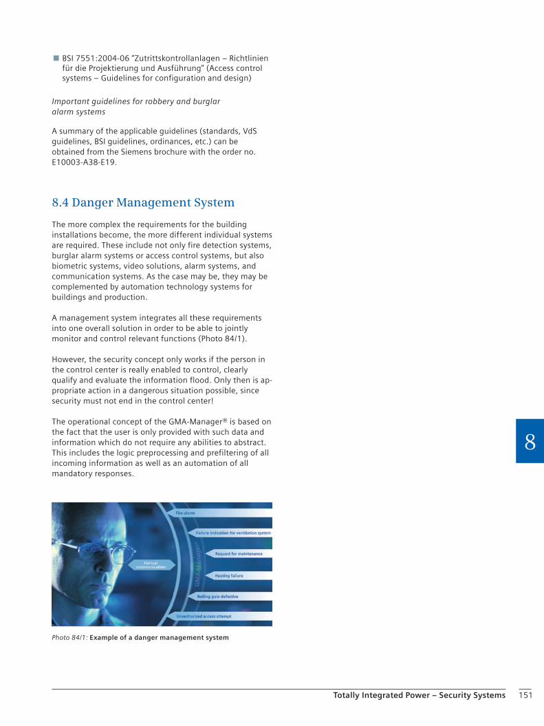
151Totally Integrated Power – Security Systems
8
BSI 7551:2004-06 “Zutrittskontrollanlagen − Richtlinien für die Projektierung und Ausführung” (Access control systems – Guidelines for configuration and design)
Important guidelines for robbery and burglar alarm systems
A summary of the applicable guidelines (standards, VdS guidelines, BSI guidelines, ordinances, etc.) can be obtained from the Siemens brochure with the order no. E10003-A38-E19.
8.4 Danger Management System
The more complex the requirements for the building installations become, the more different individual systems are required. These include not only fire detection systems, burglar alarm systems or access control systems, but also biometric systems, video solutions, alarm systems, and communication systems. As the case may be, they may be complemented by automation technology systems for buildings and production.
A management system integrates all these requirements into one overall solution in order to be able to jointly monitor and control relevant functions (Photo 84/1).
However, the security concept only works if the person in the control center is really enabled to control, clearly qualify and evaluate the information flood. Only then is ap-propriate action in a dangerous situation possible, since security must not end in the control center!
The operational concept of the GMA-Manager® is based on the fact that the user is only provided with such data and information which do not require any abilities to abstract. This includes the logic preprocessing and prefiltering of all incoming information as well as an automation of all mandatory responses.
Photo 84/1: Example of a danger management system

152 Totally Integrated Power – Security Systems
8
Chapter 9Power Quality
9.1 Electromagnetic Compatibility (EMC) 154
9.2 Power Quality 162
9.3 Lightning Protection and Grounding 170
9.4 Integration of Regenerative Energy Sources 174
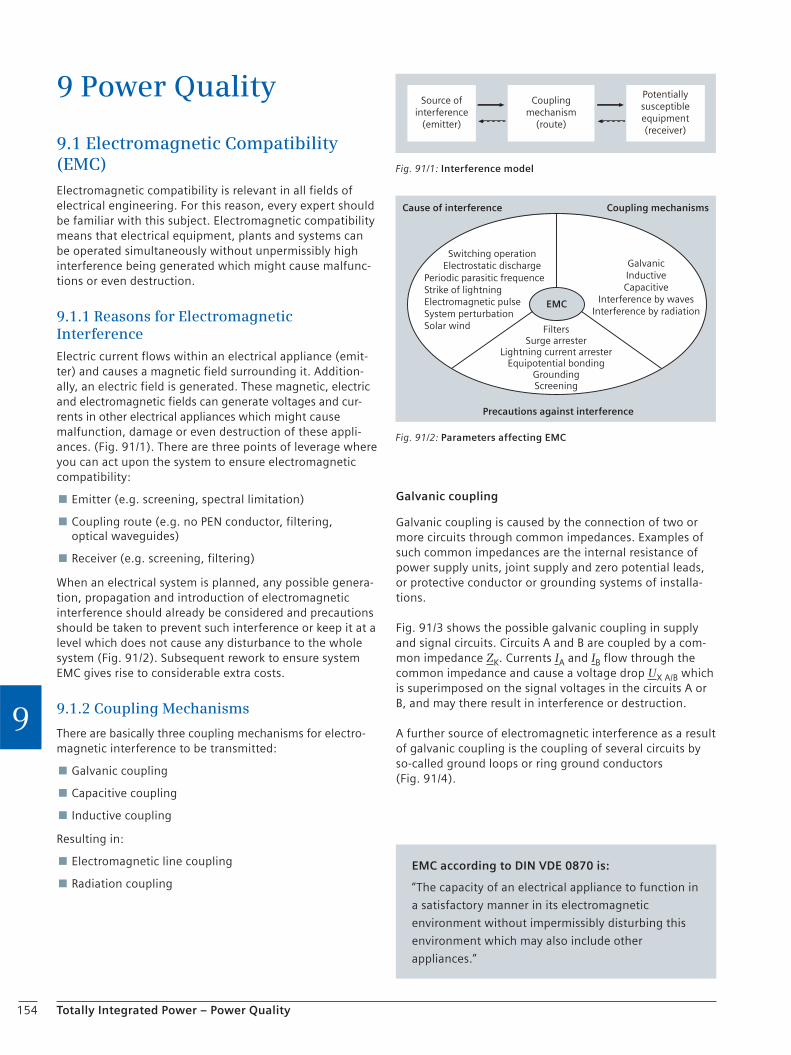
154 Totally Integrated Power – Power Quality
9
9 Power Quality
9.1 Electromagnetic Compatibility (EMC)Electromagnetic compatibility is relevant in all fields of electrical engineering. For this reason, every expert should be familiar with this subject. Electromagnetic compatibility means that electrical equipment, plants and systems can be operated simultaneously without unpermissibly high interference being generated which might cause malfunc-tions or even destruction.
9.1.1 Reasons for Electromagnetic Interference
Electric current flows within an electrical appliance (emit-ter) and causes a magnetic field surrounding it. Addition-ally, an electric field is generated. These magnetic, electric and electromagnetic fields can generate voltages and cur-rents in other electrical appliances which might cause malfunction, damage or even destruction of these appli-ances. (Fig. 91/1). There are three points of leverage where you can act upon the system to ensure electromagnetic compatibility:
Emitter (e.g. screening, spectral limitation)
Coupling route (e.g. no PEN conductor, filtering, optical waveguides)
Receiver (e.g. screening, filtering)
When an electrical system is planned, any possible genera-tion, propagation and introduction of electromagnetic interference should already be considered and precautions should be taken to prevent such interference or keep it at a level which does not cause any disturbance to the whole system (Fig. 91/2). Subsequent rework to ensure system EMC gives rise to considerable extra costs.
9.1.2 Coupling Mechanisms
There are basically three coupling mechanisms for electro-magnetic interference to be transmitted:
Galvanic coupling
Capacitive coupling
Inductive coupling
Resulting in:
Electromagnetic line coupling
Radiation coupling
Galvanic coupling
Galvanic coupling is caused by the connection of two or more circuits through common impedances. Examples of such common impedances are the internal resistance of power supply units, joint supply and zero potential leads, or protective conductor or grounding systems of installa-tions.
Fig. 91/3 shows the possible galvanic coupling in supply and signal circuits. Circuits A and B are coupled by a com-mon impedance ZK. Currents IA and IB flow through the common impedance and cause a voltage drop UX A/B which is superimposed on the signal voltages in the circuits A or B, and may there result in interference or destruction.
A further source of electromagnetic interference as a result of galvanic coupling is the coupling of several circuits by so-called ground loops or ring ground conductors (Fig. 91/4).
Source ofinterference
(emitter)
Potentiallysusceptibleequipment(receiver)
Couplingmechanism
(route)
Fig. 91/1: Interference model
Cause of interference Coupling mechanisms
Switching operationElectrostatic discharge
FiltersSurge arrester
Lightning current arresterEquipotential bonding
GroundingScreening
Precautions against interference
Periodic parasitic frequenceStrike of lightningElectromagnetic pulseSystem perturbationSolar wind
GalvanicInductiveCapacitive
Interference by wavesInterference by radiation
EMC
Fig. 91/2: Parameters affecting EMC
EMC according to DIN VDE 0870 is:
“The capacity of an electrical appliance to function in
a satisfactory manner in its electromagnetic
environment without impermissibly disturbing this
environment which may also include other
appliances.”
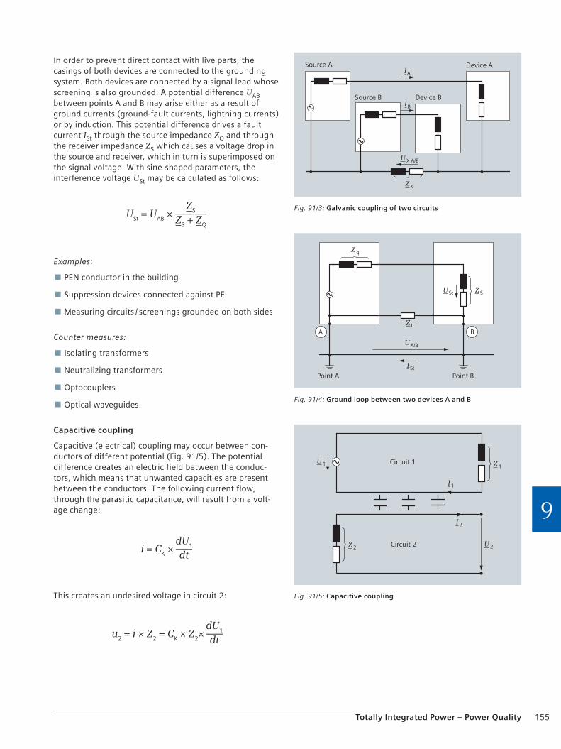
155Totally Integrated Power – Power Quality
9
In order to prevent direct contact with live parts, the casings of both devices are connected to the grounding system. Both devices are connected by a signal lead whose screening is also grounded. A potential difference UAB between points A and B may arise either as a result of ground currents (ground-fault currents, lightning currents) or by induction. This potential difference drives a fault current ISt through the source impedance ZQ and through the receiver impedance ZS which causes a voltage drop in the source and receiver, which in turn is superimposed on the signal voltage. With sine-shaped parameters, the interference voltage USt may be calculated as follows:
ZS
ZS + Z
Q
USt = U
AB × ――
Examples:
PEN conductor in the building
Suppression devices connected against PE
Measuring circuits / screenings grounded on both sides
Counter measures:
Isolating transformers
Neutralizing transformers
Optocouplers
Optical waveguides
Capacitive coupling
Capacitive (electrical) coupling may occur between con-ductors of different potential (Fig. 91/5). The potential difference creates an electric field between the conduc-tors, which means that unwanted capacities are present between the conductors. The following current flow, through the parasitic capacitance, will result from a volt-age change:
dU1
dti = C
K × ―
This creates an undesired voltage in circuit 2:
dU1
dtu
2 = i × Z
2 = C
K × Z
2× ―
Source A
Source B
Device A
Device B
I A
I B
U X A/B
Z K
Fig. 91/3: Galvanic coupling of two circuits
Point BPoint A
A BZ L
U A/B
I St
U St Z S
Z q
Fig. 91/4: Ground loop between two devices A and B
Circuit 2
Circuit 1
U 2
I 1
U 1 Z 1
Z 2
I 2
Fig. 91/5: Capacitive coupling
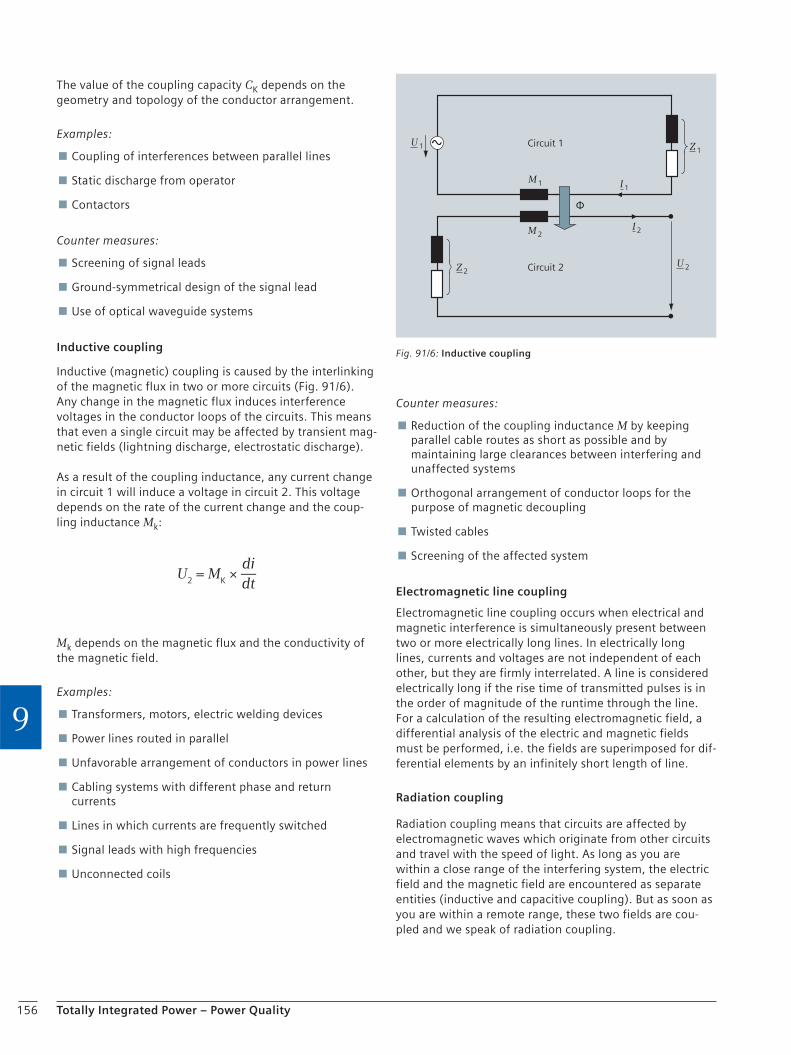
156 Totally Integrated Power – Power Quality
9
The value of the coupling capacity CK depends on the geometry and topology of the conductor arrangement.
Examples:
Coupling of interferences between parallel lines
Static discharge from operator
Contactors
Counter measures:
Screening of signal leads
Ground-symmetrical design of the signal lead
Use of optical waveguide systems
Inductive coupling
Inductive (magnetic) coupling is caused by the interlinking of the magnetic flux in two or more circuits (Fig. 91/6). Any change in the magnetic flux induces interference voltages in the conductor loops of the circuits. This means that even a single circuit may be affected by transient mag-netic fields (lightning discharge, electrostatic discharge).
As a result of the coupling inductance, any current change in circuit 1 will induce a voltage in circuit 2. This voltage depends on the rate of the current change and the coup-ling inductance Mk:
didt
U2 = M
K × ―
Mk depends on the magnetic flux and the conductivity of the magnetic field.
Examples:
Transformers, motors, electric welding devices
Power lines routed in parallel
Unfavorable arrangement of conductors in power lines
Cabling systems with different phase and return currents
Lines in which currents are frequently switched
Signal leads with high frequencies
Unconnected coils
Counter measures:
Reduction of the coupling inductance M by keeping parallel cable routes as short as possible and by maintaining large clearances between interfering and unaffected systems
Orthogonal arrangement of conductor loops for the purpose of magnetic decoupling
Twisted cables
Screening of the affected system
Electromagnetic line coupling
Electromagnetic line coupling occurs when electrical and magnetic interference is simultaneously present between two or more electrically long lines. In electrically long lines, currents and voltages are not independent of each other, but they are firmly interrelated. A line is considered electrically long if the rise time of transmitted pulses is in the order of magnitude of the runtime through the line. For a calculation of the resulting electromagnetic field, a differential analysis of the electric and magnetic fields must be performed, i.e. the fields are superimposed for dif-ferential elements by an infinitely short length of line.
Radiation coupling
Radiation coupling means that circuits are affected by electromagnetic waves which originate from other circuits and travel with the speed of light. As long as you are within a close range of the interfering system, the electric field and the magnetic field are encountered as separate entities (inductive and capacitive coupling). But as soon as you are within a remote range, these two fields are cou-pled and we speak of radiation coupling.
Circuit 1
Circuit 2
M 1 I 1
M 2
Z 1U 1
U 2Z 2
I 2
Φ
Fig. 91/6: Inductive coupling

157Totally Integrated Power – Power Quality
9
9.1.3 Practical Issues and Requirements on EMC-friendly Power Supply Systems
For several years, increasing malfunction of and damage to electrical and electronic equipment has been noticed, for example
UnaccounTable faults in data transmission networks
Desktop and server crashes
Printer failures
Slowdown of data transmission in local networks, even to complete standstill
Triggering of alarm systems and fire detectors
Corrosion in piping and ground conductors
The reasons for these effects often lie in an old-style power supply system where the N conductor and the PE conduc-tor are combined to form a single PEN conductor. This wasn’t a problem in the old days, as the number of elec-tronic equipment connected into supply was low. The phases were loaded nearly symmetrically, and conse-quently the PEN conductor was hardly loaded.
Owing to an increasing number of high-power single-phase loads, and loads with a high proportion of harmonic contents in the third order (switched power supply units), the phases are loaded extremely asymmetrically, and the N conductor is sometimes loaded with a higher current than the phase conductors. As the PE conductor is meant to carry current only in case of a fault, the PE conductor and the N conductor must be laid separately in new power supply systems (VDE 0100 Part 540 Appendix C.2). If this requirement is not observed in an electrical installation, part of the return current might be distributed through all grounding systems and equipotential conductors. Current flows back to the voltage source through the smallest resistors, so that unwanted currents might even flow through metal pipes and screens of data cables.
These “stray” currents may give rise to strong electromag-netic fields which cause strange failures and malfunction of electronic equipment. They may also cause corrosion in water pipes. Since higher currents may be present in the N conductor, as explained above, care must be taken not to reduce the cross section of the N conductor as compared to that of the phase conductors, but even to increase it.
Effects of conductor design on EMC
Fig. 91/7 demonstrates which problems must be expected if the PE and N conductors are combined to form a PEN conductor. The illustration shows a device through which the current IL flows during operation. Normally, this cur-rent should be taken back to the source through the PEN conductor. This return current, however, causes a voltage drop in the PEN conductor, which acts as an interference voltage on all systems connected to the PEN conductor, resulting in a parasitic current ISt through the device
screening and a parasitic current Ibuilding in the building. The parasitic currents flowing through the cable screens interfere with or destroy equipment which is susceptible to overvoltages. Moreover, parasitic currents in the building may result in corrosion and give rise to magnetic fields which may cause further damage. Separate design of the N conductor and PE conductor will prevent such stray cur-rents. Thus, the PE conductor only carries current in case of a fault (Fig. 91/8).
Distributor
ON
Distributor
Transformer
Screen
Token ring
Conductive buildingstructure, water pipe
IL = Current in phase conductor LIN = Neutral conductor current in PE NIG = Stray current in the buildingISt = Parasitic currents in screens∆U = Voltage drop in PE N conductor (external voltage)
IL
ISt
IN
IL
ISt
ISt
ILIPE N
PE N L
∆U
> 0
IG
Fig. 91/7: Current flow with combined PEN conductor
Distributor
ON
Distributor
Transformer
Screen
Token ring
Conductive buildingstructure, water pipe
IL = Current in phase conductor LIN = Neutral conductor current in NIG = Stray current in the buildingISt = Parasitic currents in screens∆U = Voltage drop in PE conductor (external voltage)
ISt = 0
PE LN
IN IL
ILIN
IG = 0
IL
∆U
= 0
Fig. 91/8: Current flow for separate PE and N conductors

158 Totally Integrated Power – Power Quality
9
Power supply systems
In order to avoid parasitic currents, the type of power supply system must be carefully selected. The following section explains two typical examples for coupling the normal power supply (NPS network) and the safety power supply (SPS network). In the first case, the SPS is installed in the immediate vicinity of the NPS (central feed-in) and in the second case, the SPS is installed remote from the NPS (distributed feed-in).
Power supply system for central feed-in
The power supply system shown in Fig. 91/9 is recom-mended for central feed-in, with EMC being ensured even when the supplying sources of sections A and B are oper-ated in parallel. We recommend that the PEN conductor be marked in light blue and, additionally, in green-yellow throughout its course.
The following should be observed for this kind of power supply system:
The PEN conductor must be wired separately along its whole course, both in the SPS and in the NPS, as well as in the LVMD.
There must be no connection between the neutral points of transformer and generator, and ground or the PE conductor, respectively.
The feeder switches for supply from SPS and NPS must be in 3-pole design.
The supplying sources for sections A and B may be operated in parallel.
A connection between ground and the PE conductor may only be made at one point (central grounding point), as otherwise the PE conductor and the N conductor would be connected in parallel, resulting in unfavorable EMC conditions as shown in Fig. 91/9.
All load feeders are designed as a TN-S system, i.e. with distributed N-conductor function and separate PE and N conductors. 3-pole and 4-pole switching devices may be used.
Power supply system for distributed feed-in
Fig. 91/10 depicts the recommended system for distributed feed-in. Distributed feed-in is encountered if the following applies to the distance between sections A and B:
a1 >> a2
As short-circuit currents decrease with distance from the main equipotential bonding conductor, and protective devices require a certain minimum value for safe tripping in the event of a fault, and as selective grading must also be taken into account, a second main equipotential bond-ing conductor is installed for distributed feed-in of the SPS.
The following should be observed for this kind of power supply system:
The PEN conductor must be wired separately along its whole course in the NPS.
There must be no connection between the neutral point of the transformer and ground or the PE conductor, respectively. Between the neutral point of the generator and ground or the PE conductor, respectively, a connection for an additional main equipotential bonding conductor is installed.
A parallel operation between sections A and B is not permitted. The transformers may supply sections A and B at the same time. The generator, however, can only supply section B.
Note: During changeover from transformer to generator operation, parallel operation is possible under unfavorable EMC conditions for a short time, for example during back synchronization.
The switches of the changeover connection in the SPS and the generator supply must be in 4-pole design. The feeder switches for supply of section A must be in 3-pole design.
All load feeders are designed as a TN-S system, i.e. with distributed N-conductor function and separate PE and N conductors. 3-pole and 4-pole switching devices may be used.
By implementing a central grounding point in the power supply systems described above, suiTable measuring devices can be used to make sure that no further – imper-missible – splitter bridge between the N conductor and the PE conductor was installed.
Overview of power supply systems according to their connection to earth and their relation to EMC
An overview and evaluation of the different power supply systems with regard to EMC can be found in the standard DIN VDE 0800-2-548. Besides the TN-S system, IT and TT systems are also EMC-friendly systems. Further details can be seen in Table N.1 in the standard.
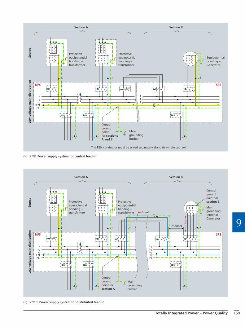
159Totally Integrated Power – Power Quality
9SPSNPS
Low
-vo
ltag
e m
ain
dis
trib
uti
on
Sou
rce
Section A Section B
Interlock
Centralgroundpoint forsection B
Centralgroundpoint forsection A
Main grounding busbar
Protective equipotential bonding – transformer
Main grounding terminal – Generator
Protective equipotential bonding – transformer
L1L2L3
PENPE
L1L2L3N
PE
a1
a 2
Fig. 91/10: Power supply system for distributed feed-in
Fig. 91/9: Power supply system for central feed-in
SPSNPS
Low
-vo
ltag
e m
ain
dis
trib
uti
on
Sou
rce
Section A Section B
Centralgroundpointfor sectionsA and B
Protective equipotential bonding – transformer
Equipotential bonding – Generator
Protective equipotential bonding – transformer
Main grounding busbar
The PEN conductor must be wired separately along its whole course!
L1L2L3
PENPE
L1L2L3
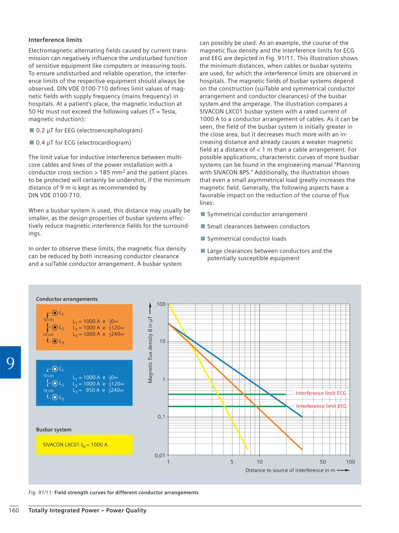
160 Totally Integrated Power – Power Quality
9
Interference limits
Electromagnetic alternating fields caused by current trans-mission can negatively influence the undisturbed function of sensitive equipment like computers or measuring tools. To ensure undisturbed and reliable operation, the interfer-ence limits of the respective equipment should always be observed. DIN VDE 0100-710 defines limit values of mag-netic fields with supply frequency (mains frequency) in hospitals. At a patient's place, the magnetic induction at 50 Hz must not exceed the following values (T = Tesla, magnetic induction):
0.2 μT for EEG (electroencephalogram)
0.4 μT for ECG (electrocardiogram)
The limit value for inductive interference between multi-core cables and lines of the power installation with a conductor cross section > 185 mm2 and the patient places to be protected will certainly be undershot, if the minimum distance of 9 m is kept as recommended by DIN VDE 0100-710.
When a busbar system is used, this distance may usually be smaller, as the design properties of busbar systems effec-tively reduce magnetic interference fields for the surround-ings.
In order to observe these limits, the magnetic flux density can be reduced by both increasing conductor clearance and a suiTable conductor arrangement. A busbar system
can possibly be used. As an example, the course of the magnetic flux density and the interference limits for ECG and EEG are depicted in Fig. 91/11. This illustration shows the minimum distances, when cables or busbar systems are used, for which the interference limits are observed in hospitals. The magnetic fields of busbar systems depend on the construction (suiTable and symmetrical conductor arrangement and conductor clearances) of the busbar system and the amperage. The illustration compares a SIVACON LXC01 busbar system with a rated current of 1000 A to a conductor arrangement of cables. As it can be seen, the field of the busbar system is initially greater in the close area, but it decreases much more with an in-creasing distance and already causes a weaker magnetic field at a distance of < 1 m than a cable arrangement. For possible applications, characteristic curves of more busbar systems can be found in the engineering manual “Planning with SIVACON 8PS.” Additionally, the illustration shows that even a small asymmetrical load greatly increases the magnetic field. Generally, the following aspects have a favorable impact on the reduction of the course of flux lines:
Symmetrical conductor arrangement
Small clearances between conductors
Symmetrical conductor loads
Large clearances between conductors and the potentially susceptible equipment
Fig. 91/11: Field strength curves for different conductor arrangements
Conductor arrangements
Mag
net
ic fl
ux
den
sity
B in
µT
Distance to source of interference in m
Interference limit ECG
Interference limit EEG
Busbar system
SIVACON LXC01 IN = 1000 A
0,1
1
1 10 505 100
10
100
10 cm
10 cm
L1
L1 = 1000 A e -j0∞L2 = 1000 A e -j120∞L3 = 950 A e -j240∞
L2
L3
10 cm
10 cm
L1
L1 = 1000 A e -j0∞L2 = 1000 A e -j120∞L3 = 1000 A e -j240∞
L2
L3
0,01

161Totally Integrated Power – Power Quality
9
9.1.4 Overview of EMC-relevant Standards
DIN EN 50174-2 (VDE 0800 Part 174-2)
Information technology – Cabling installation – Part 2: Installation planning and practices inside buildings
DIN EN 50310 (VDE 0800 Part 2-310)
Application of equipotential bonding and earthing in buildings with information technology equipment
DIN VDE 0100-443 (VDE 0100 Part 443)
Low-voltage electrical installations – Part 4 Protection for safety – chapter 44: Protection against voltage disturbances and electromagnetic disturbances – clause 443: Protection against overvoltages of atmospheric origin or due to switching
DIN VDE 0100-540 (VDE 0100 Part 540)
Low-voltage electrical installations – Selection and erection of electrical equipment – Earthing arrangements, protective conductors and protective bonding conductors
DIN VDE 0100-444 (VDE 0100 Part 444)
Electrical installations of buildings – Part 4: Protection for safety; chapter 44: Protection against voltage disturbances and electromagnetic disturbances – clause 444: Protection against electromagnetic interferences in installations of buildings

162 Totally Integrated Power – Power Quality
9
9.2 Power Quality
Since 2001 there has been a steep rise in electricity prices, thus electricity cost is becoming an ever growing part of monthly fixed costs from an entrepreneurial point of view. For reasons of environmental and climate protection, not only out of business interest, should a greatest possible energy performance and quality come to the fore while costs are simultaneously minimized, especially since there are significant quality differences of electric energy.
The IEC – International Electrotechnical Commission – an international standardization committee residing at Geneva – defines the term “power quality” as follows:
“Characteristic property of electricity at a given position in the electrical energy system, where these properties must be contrasted with certain technical parameters”
Fig. 92/1: Parameters and interference factors of the system voltage
Source of interference
Switch
Machine
Motor
Restrike
Spike
Current peak
Phase displacement Reactive power
Voltage change
Overvoltage
Transient
Harmonic
Atmospheric discharge
Interference phenomenon Effect
Frequency converter

163Totally Integrated Power – Power Quality
9
9.2.1 System Voltage Quality
The following parameters are relevant for the system voltage quality in accordance with the European standard EN 50160:
Voltage magnitude, slow voltage changes
Interruptions of supply (short, long)
Voltage dips
Fast voltage changes, flicker
Voltage asymmetry, voltage shape (harmonics, subharmonic, signal voltages)
Transient overvoltages and overvoltages with supply frequency
Frequency
A high power quality is defined by a high degree of compli-ance with the standard values.
The reasons for deficient system voltage quality lie both on the part of the network operators and on the part of the connected customers. The latter are faced with voltage distortions and flicker effects owing to system perturba-tions from customer installations.
Problems in the transmission and distribution network result, among other things, in shorter or longer interrup-tions. The reliability of power generation also plays an important part with regard to system voltage quality.
Fig. 92/1 shows important parameters of the supply volt-age as well as known interference factors. Multi-function measuring instruments are used for measuring the most important power quality parameters.
SuiTable measures for a sustainable power quality optimi-zation are among others reactive power compensation systems and active network filters.
9.2.2 Reactive Power
The total power, the so-called apparent power, of a trans-mission network is composed of active and reactive power (Fig. 92/2). While the power consumers connected into supply transform the active energy, the reactive energy is not consumed. The reactive power at the consumer side is merely used for building up a magnetic field, for example for operating electric motors, pumps or transformers.
Reactive power is generated when power is drawn from the supply network and then fed back into the network with a time delay – this way it oscillates between con-sumer and generator (Fig. 92/3).
This constitutes an additional load on the network and requires greater dimensioning in order to take up the oscillating reactive power in addition to the active power made available.
As a result: less active current can be transmitted.
Legend:
Active power
Reactive powernon-compensated
Apparent powerprior to compensation
Phase angle
SQ
P
φ
P
Q
S
φ
Fig. 92/3: Interrelation of different power types
Fig. 92/2: Composition of the total power of a transmission grid
Apparent powerActive power
Magnetic field
Reactive power
Motor DriveGrid of the power supplier

164 Totally Integrated Power – Power Quality
9
Solution
With a reactive power compensation system with power capacitors directly connected to the low-voltage network and close to the power consumer, transmission facilities can be relieved, as reactive power is no longer supplied from the network but provided by the capacitors (Fig. 92/4).
Transmission losses are reduced, energy consumption costs are cut and expensive expansions become unnecessary, as the same equipment can be used to transmit more active power owing to reactive power compensation.
Determination of capacitor power
A system with the installed active power P shall be com-pensated from a power factor cos φ1 to a power factor cos φ2. The capacitor power necessary for this compensa-tion is calculated as follows:
Qc = P × (tan φ1 – tan φ2)
Compensation reduces the transmitted apparent power S.
Ohmic transmission losses decrease by the square of the currents.
Determination of reactive power in operating networks
For installations which are still in a configuring stage, it can be assumed by approximation that the reactive power consumers are primarily induction motors working with an average power factor cos φ ≥ 0.7. For compensation to cos φ = 0.9 a capacitor power of approximately 50 % of the active power is required:
Qc = 0.5 × P
For installations which are already running, the required capacitor power can be determined by measuring. If active and reactive work meters are available, the demand of capacitor power can be taken from the monthly electricity bill.
For calculation method see section 5.5, page 94.
If reactive work meters are not available, the capacitor power can be determined by using reactive and active power recorders (Fig. 92/5).
Fig. 92/4: Principle of reactive power compensation using low-voltage power capacitors
Legend:
Active power
Reactive powernon-compensated
Apparent powerprior to compensation
Phase angle
Residual reactive powerafter compensation
Apparent powerafter compensation
Connectedcapacitor power
P
Q1
S1
φ
Q2
S2
Qc
S2
Q2 Qc
Q1
P
φ2φ1
Fig. 92/5: Power diagram for a non-compensated (1) and a compensated (2) installation
Supply from medium-voltage network
20 kV
400 V
M
Iw Ib
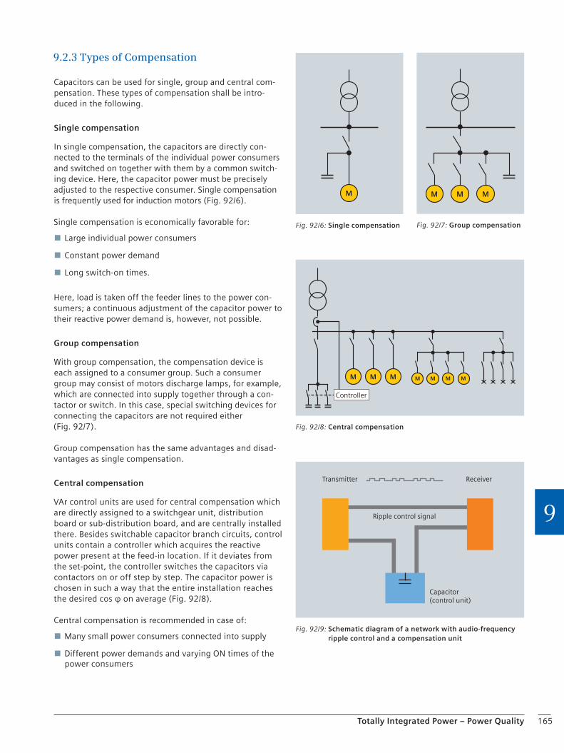
165Totally Integrated Power – Power Quality
9
9.2.3 Types of Compensation
Capacitors can be used for single, group and central com-pensation. These types of compensation shall be intro-duced in the following.
Single compensation
In single compensation, the capacitors are directly con-nected to the terminals of the individual power consumers and switched on together with them by a common switch-ing device. Here, the capacitor power must be precisely adjusted to the respective consumer. Single compensation is frequently used for induction motors (Fig. 92/6).
Single compensation is economically favorable for:
Large individual power consumers
Constant power demand
Long switch-on times.
Here, load is taken off the feeder lines to the power con-sumers; a continuous adjustment of the capacitor power to their reactive power demand is, however, not possible.
Group compensation
With group compensation, the compensation device is each assigned to a consumer group. Such a consumer group may consist of motors discharge lamps, for example, which are connected into supply together through a con-tactor or switch. In this case, special switching devices for connecting the capacitors are not required either (Fig. 92/7).
Group compensation has the same advantages and disad-vantages as single compensation.
Central compensation
VAr control units are used for central compensation which are directly assigned to a switchgear unit, distribution board or sub-distribution board, and are centrally installed there. Besides switchable capacitor branch circuits, control units contain a controller which acquires the reactive power present at the feed-in location. If it deviates from the set-point, the controller switches the capacitors via contactors on or off step by step. The capacitor power is chosen in such a way that the entire installation reaches the desired cos φ on average (Fig. 92/8).
Central compensation is recommended in case of:
Many small power consumers connected into supply
Different power demands and varying ON times of the power consumers
M
Fig. 92/6: Single compensation
MM M
Fig. 92/7: Group compensation
Controller
MM M MM M M
Fig. 92/8: Central compensation
Transmitter
Ripple control signal
Capacitor(control unit)
Receiver
Fig. 92/9: Schematic diagram of a network with audio-frequency ripple control and a compensation unit
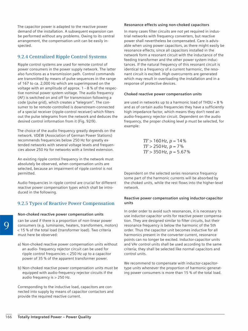
166 Totally Integrated Power – Power Quality
9
The capacitor power is adapted to the reactive power demand of the installation. A subsequent expansion can be performed without any problems. Owing to its central arrangement, the compensation unit can be easily in-spected.
9.2.4 Centralized Ripple Control Systems
Ripple control systems are used for remote control of power consumers in the power supply network. The latter also functions as a transmission path. Control commands are transmitted by means of pulse sequences in the range of 167 to ca. 2,000 Hz which are superimposed on the voltage with an amplitude of approx. 1 – 8 % of the respec-tive nominal power system voltage. The audio frequency (AF) is switched on and off for transmission following a code (pulse grid), which creates a “telegram”. The con-sumer to be remote-controlled is downstream-connected of a special receiver (ripple-control receiver) which filters out the pulse telegrams from the network and deduces the desired control information from it (Fig. 92/9).
The choice of the audio frequency greatly depends on the network. VDEW (Association of German Power Stations) recommends frequencies below 250 Hz for greatly ex-tended networks with several voltage levels and frequen-cies above 250 Hz for networks with a limited extension.
An existing ripple control frequency in the network must absolutely be observed, when compensation units are selected, because an impairment of ripple control is not permitted.
Audio frequencies in ripple control are crucial for different reactive power compensation types which shall be intro-duced in the following.
9.2.5 Types of Reactive Power Compensation
Non-choked reactive power compensation units
can be used if there is a proportion of non-linear power consumers (e.g. luminaires, heaters, transformers, motors) < 15 % of the total load (transformer load). Two criteria must here be observed:
a) Non-choked reactive power compensation units without an audio- frequency rejector circuit can be used for ripple control frequencies < 250 Hz up to a capacitor power of 35 % of the apparent transformer power.
b) Non-choked reactive power compensation units must be equipped with audio-frequency rejector circuits if the audio frequency is > 250 Hz.
Corresponding to the inductive load, capacitors are con-nected into supply by means of capacitor contactors and provide the required reactive current.
Resonance effects using non-choked capacitors
In many cases filter circuits are not yet required in indus-trial networks with frequency converters, but reactive power shall nevertheless be compensated. Care is advis-able when using power capacitors, as there might easily be resonance effects; since all capacitors installed in the network form a resonant circuit with the inductance of the feeding transformer and the other power system induc-tances. If the natural frequency of this resonant circuit is identical to a frequency of a current harmonic, the reso-nant circuit is excited. High overcurrents are generated which may result in overloading the installation and in a response of protective devices.
Choked reactive power compensation units
are used in networks up to a harmonic load of THDU = 8 % and as of certain audio frequencies they have a sufficiently high impedance factor, which means they don't need an audio-frequency rejector circuit. Dependent on the audio frequency, the proper choking level p must be selected, for example:
TF > 160 Hz, p = 14%TF > 250 Hz, p = 7%TF > 350 Hz, p = 5.67%
Dependent on the selected series resonance frequency some part of the harmonic currents will be absorbed by the choked units, while the rest flows into the higher-level network.
Reactive power compensation using inductor-capacitor units
In order order to avoid such resonances, it is necessary to use inductor-capacitor units for reactive power compensa-tion. They are designed similar to filter circuits, but their resonance frequency is below the harmonic of the 5th order. Thus the capacitor unit becomes inductive for all harmonics present in the converter current, resonance points can no longer be excited. Inductor-capacitor units and VAr control units shall be used according to the same criteria; they shall be selected like normal capacitors and control units.
We recommend to compensate with inductor-capacitor-type units whenever the proportion of harmonic-generat-ing power consumers is more than 15 % of the total load.
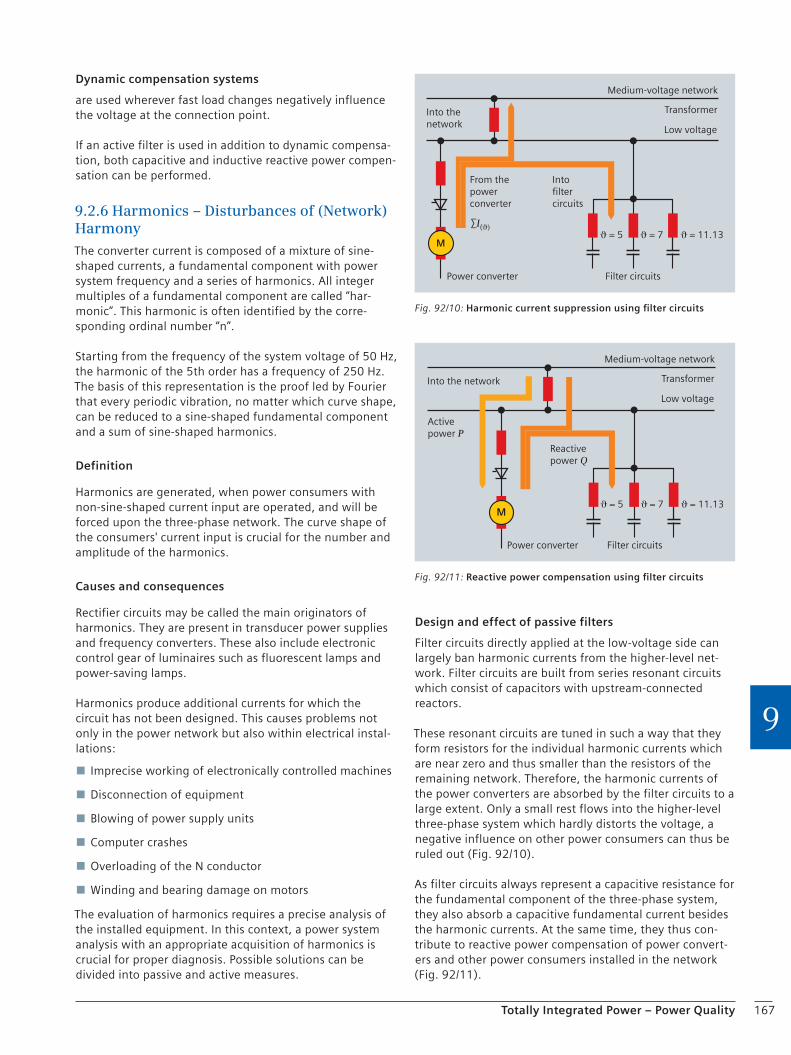
167Totally Integrated Power – Power Quality
9
Dynamic compensation systems
are used wherever fast load changes negatively influence the voltage at the connection point.
If an active filter is used in addition to dynamic compensa-tion, both capacitive and inductive reactive power compen-sation can be performed.
9.2.6 Harmonics – Disturbances of (Network) Harmony
The converter current is composed of a mixture of sine-shaped currents, a fundamental component with power system frequency and a series of harmonics. All integer multiples of a fundamental component are called “har-monic”. This harmonic is often identified by the corre-sponding ordinal number “n”.
Starting from the frequency of the system voltage of 50 Hz, the harmonic of the 5th order has a frequency of 250 Hz. The basis of this representation is the proof led by Fourier that every periodic vibration, no matter which curve shape, can be reduced to a sine-shaped fundamental component and a sum of sine-shaped harmonics.
Definition
Harmonics are generated, when power consumers with non-sine-shaped current input are operated, and will be forced upon the three-phase network. The curve shape of the consumers' current input is crucial for the number and amplitude of the harmonics.
Causes and consequences
Rectifier circuits may be called the main originators of harmonics. They are present in transducer power supplies and frequency converters. These also include electronic control gear of luminaires such as fluorescent lamps and power-saving lamps.
Harmonics produce additional currents for which the circuit has not been designed. This causes problems not only in the power network but also within electrical instal-lations:
Imprecise working of electronically controlled machines
Disconnection of equipment
Blowing of power supply units
Computer crashes
Overloading of the N conductor
Winding and bearing damage on motors
The evaluation of harmonics requires a precise analysis of the installed equipment. In this context, a power system analysis with an appropriate acquisition of harmonics is crucial for proper diagnosis. Possible solutions can be divided into passive and active measures.
Design and effect of passive filters
Filter circuits directly applied at the low-voltage side can largely ban harmonic currents from the higher-level net-work. Filter circuits are built from series resonant circuits which consist of capacitors with upstream-connected reactors.
These resonant circuits are tuned in such a way that they form resistors for the individual harmonic currents which are near zero and thus smaller than the resistors of the remaining network. Therefore, the harmonic currents of the power converters are absorbed by the filter circuits to a large extent. Only a small rest flows into the higher-level three-phase system which hardly distorts the voltage, a negative influence on other power consumers can thus be ruled out (Fig. 92/10).
As filter circuits always represent a capacitive resistance for the fundamental component of the three-phase system, they also absorb a capacitive fundamental current besides the harmonic currents. At the same time, they thus con-tribute to reactive power compensation of power convert-ers and other power consumers installed in the network (Fig. 92/11).
Power converter Filter circuits
From the power converter
Into filter circuits
ϑ = 5 ϑ = 7 ϑ = 11.13
Into the network
Medium-voltage network
Transformer
Low voltage
∑I(ϑ)
M
Fig. 92/10: Harmonic current suppression using filter circuits
Fig. 92/11: Reactive power compensation using filter circuits
Power converter Filter circuits
Active power P
Reactive power Q
Into the network
Medium-voltage network
Transformer
Low voltage
ϑ = 5 ϑ = 7 ϑ = 11.13M
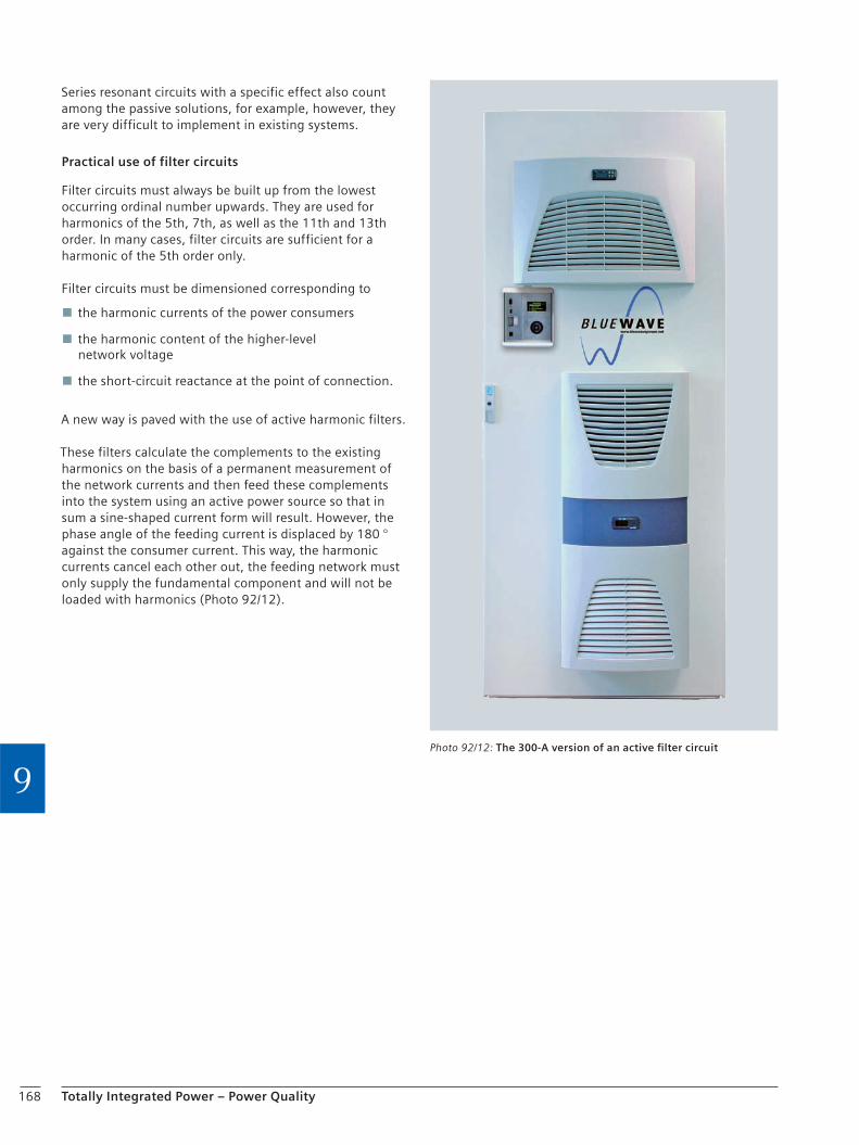
168 Totally Integrated Power – Power Quality
9
Series resonant circuits with a specific effect also count among the passive solutions, for example, however, they are very difficult to implement in existing systems.
Practical use of filter circuits
Filter circuits must always be built up from the lowest occurring ordinal number upwards. They are used for harmonics of the 5th, 7th, as well as the 11th and 13th order. In many cases, filter circuits are sufficient for a harmonic of the 5th order only.
Filter circuits must be dimensioned corresponding to
the harmonic currents of the power consumers
the harmonic content of the higher-level network voltage
the short-circuit reactance at the point of connection.
A new way is paved with the use of active harmonic filters.
These filters calculate the complements to the existing harmonics on the basis of a permanent measurement of the network currents and then feed these complements into the system using an active power source so that in sum a sine-shaped current form will result. However, the phase angle of the feeding current is displaced by 180 ° against the consumer current. This way, the harmonic currents cancel each other out, the feeding network must only supply the fundamental component and will not be loaded with harmonics (Photo 92/12).
Photo 92/12: The 300-A version of an active filter circuit

169Totally Integrated Power – Power Quality
9
9.2.7 Monitoring and Analysis of Voltage Quality
A reliable supply with electric energy is the backbone of our modern society. Besides availability, the voltage quality of the energy is more and more in the focus of attention. The increasing use of power electronics causes problems of voltage quality. At the same time, users are more and more aware of the consequences of voltage fluctuations. After all, an insufficient voltage quality can lead to inter-ruptions, production losses and high follow-up costs.
This is an aspect which affects both power suppliers and planners. To this end, so-called voltage characteristics are defined in EN 50160 and laid down as standard.
What are the most important criteria for voltage quality?
Constant sine curve
Constant frequency
Symmetry
Constant averages across a longer period of time
Which network phenomena can impair the voltage quality?
Interruptions of power supply
Voltage dips
Harmonics
Transients
Asymmetries
Frequency deviations
Flicker
When should measures for voltage quality measurement be taken into consideration as early as in the planning stage?
Are loads causing system perturbations applied in this network or in its higher-level network, like:
Motors
Three-phase electric arc furnaces
Resistance welding machines
Non-compensated switched-mode power supply units
Switching of loads
Then a measuring concept consisting of a quality recorder and appropriate evaluations should already be considered in planning. Harmonic currents let the power demand rise as compared to harmonic-free power purchase, which inevitably results in higher costs.
Voltage quality starts with measurements
A reliable acquisition and evaluation of the system voltage according to generally applicable quality criteria is the basis to recognize possible problems early and to respond to them properly by taking appropriate action. The use of appropriate measuring instruments (e.g. a quality recorder, Photo 92/13) is the basis for quality measurements in order to monitor the entire chain from the power distribution system to the power consumer. Current and voltage are generally measured at the following locations in the net-work using permanently installed measuring instruments:
Feed-in point of the power supply SIMEAS Q80 / PAC4200
At the busbars of the LV main distribution PAC4200, PAC3200
In every outgoing circuit of the LVMD (if there are several flicker-producing loads)
Besides the measuring instrument, an evaluation software is required as a solution for monitoring the power quality in order to see more than just a momentary picture of a fault or a deviation. Furthermore, limit-value violations are continuously monitored in compliance with EN 50160 and an appropriate PQ report is periodically generated. Alterna-tively, it shall be possible to adjust limit values in line with the contractual terms of the local power supplier.
Quality verification
On the one hand, a “clean” current with constant voltage is required for operating plants and processes in order to continuously ensure high quality. Measurements help in this case in order to demonstrate the quality of the pro-cured energy. On the other hand, industrial production causes perturbations on the electrical supply grid – with far-reaching consequences also for the originator. In this case, a clear proof will help that the responsibility for this is not borne by your your company.
Photo 92/13: SIMEAS Q80 – the quality recorder
170 Totally Integrated Power – Power Quality
9
Recorders
SIMEAS Q80 measuring instruments are installed at the individual measuring points to monitor the power quality. Via a communication link – Ethernet or a digital or analog modem – the instruments are connected to a central computer for evaluation (Model configuration Fig. 92/14). All instrument settings can be performed from this PC. It is the basis for the actual power quality analysis as well as for reports using the SIMEAS Q80-Manager software.
Functional scope
SIMEAS Q80 provides a wide functional scope – ranging from precise measurement data acquisition to automatic reporting:
Display of measurement data: voltage, current, power, frequency
Detection of asymmetrical network loads
Detection of harmonic and subharmonic content
Flicker monitoring
Detection and monitoring of supply interruptions
Analysis of ripple control signals
Determination of the direction of energy flow of harmonic components
Detection and localization of fault events in the power supply network
Automatic notification via e-mail, SMS or fax in the event of a fault
Automatic reporting
Comprehensive functions for evaluation
Fig. 92/14: Model confi guration for a PQ monitoring system
Hall 1
SIMEAS Q80 ManagerEvaluation workstation 1
SIMEAS Q80 ManagerEvaluation workstation 2
GPStime synchronization
Hall 2 Hall 3
GPStime synchronization
GPStime synchronization
Ethernet
SIMEAS Q80
Modem
Modem
SIMEAS Q80
Ethernet
Ethernet

171Totally Integrated Power – Power Quality
9
9.3 Lightning Protection and GroundingPlanning and configuring lightning protection systems primarily is about keeping dangerous strikes of lightning specifically away from building structures, thus protecting them against damage or destruction.
Since microprocessor technology has entered our build-ings, it is no longer sufficient to keep strikes of lightning “merely” away from building structures. It is equally impor-tant to protect technical installations in buildings against the effects of lightning current during its way through the lightning protection system.
Ground electrode
Besides its function to improve protective equipotential bonding, ground electrodes are an important element of lightning protection. The grounding system takes over the task to discharge the lightning current fed from the arrest-ers via the grounding system to the soil. The more low-ohmic the ground contact resistance can be made, the less installation parts or people in the vicinity are affected. If the grounding electrode and the equipotential bonding conductor are altogether conductively connected, they form an important protection system. Such a system can reduce the effects of faults between electrical and other mechanical, conductive equipment (e.g. gas and water sys-tems, central heating systems, electronic and IT systems).
9.3.1 Basics of Planning and Definitions
The basics of planning regarding concrete-footed ground electrodes are described in the DIN 18014 standard. In this standard, explanations on the most important terms relating to grounding systems can be found.
Ground
Part of the soil which is in electrical contact with a ground electrode and whose electric potential does not necessarily equal to zero.
Ground electrode
Conductive part which is embedded in the soil or in another conductive medium, e.g. concrete, which itself is in contact with the soil. The following ground electrodes are distinguished:
Buried ground rods which are driven vertically into the soil
Strip electrodes which are laid horizontally
Concrete-footed ground electrodes as a special form of strip electrodes
Owing to the humidity in the soil, ground electrodes run the risk of being destroyed by corrosion or by forming a galvanic cell with other metal parts. This must be taken into consideration when a material is selected.
Note: Piping networks of the public water supply used to be used as ground electrodes. According to DIN VDE 0100-410, this is now forbidden.
Concrete-footed ground electrode
Conductive part which is buried in the concrete of a build-ing foundation, generally as a closed ring.
Ring ground conductor
Conductive part which is buried in the soil or in the bed-ding as a closed ring and not insulated against the soil.
Grounding system
All electrical connections and appliances used for ground-ing a network, an installation or an item of equipment (e.g. mast foots, reinforcements, metal cable sheaths) and grounding conductors.
Grounding conductor
Conductor which makes a current path or part thereof between a given point in the network, an installation or an item of equipment and a ground electrode or the ground electrode network (e.g. the connection line between the equipotential bonding bar and the grounding system).
Connection part
An electrically conducting part of a concrete-footed ground electrode / ring ground conductor which enables it to be connected to other conductive parts, for example with
the equipotential bonding bar (main grounding busbar) for protective equipotential bonding
the down leads of a lightning protection system
other constructional parts made of metal
additional equipotential bonding bars.
Connection lug
Connecting conductor between a concrete-footed ground electrode and other conductive parts outside the foundation.
Connection plate (e.g. grounding fixpoint)
A electrically conducting constructive component buried in concrete which is used like a connection lug.

172 Totally Integrated Power – Power Quality
9
Equipotential bonding
Interconnection of conductive parts providing equipoten-tial bonding between those parts.
Protective bonding conductor
Protective conductor provided for protective equipotential bonding.
Main grounding busbar
Connection point, terminal or busbar which is part of the grounding system and enables the electric connection of several conductors for grounding purposes.
Sealed tanking
A tanking made of bitumen or plastic, enclosing the build-ing from all sides in the area with earth contact (also called black tanking) or a construction made of water-imperme-able concrete (also called white tanking) as well as com-bined tankings (e.g. a foundation slab made of water-im-permeable concrete in combination with tanking on the basement walls.)
Perimeter insulation
Heat insulation which encloses the parts of the building with earth contact from outside.
Movement joint
Joint between two structural components which enables expansions, settlements and the like so that no damaging mechanical stress arises at these structural components.
9.3.2 Concrete-footed Ground Electrode
Functions of the concrete-footed ground electrode according to standards
Ground fault and protective conductor currents are conducted to earth (DIN VDE 0100-540, IEC 60364-5-54)
Grounding system for external protection against lightning (DIN EN 62305-3, IEC 62305-3)
Effectivity increase of protective equipotential bonding (DIN VDE 0100-410, 60364-4-41)
Overvoltage protection (DIN VDE 0100-444, IEC 60364-4-444)
Protective grounding of antenna systems (DIN VDE 0855-300)
Concrete-footed ground electrode – design
Ground electrodes are part of the electrical installation behind the building's service entrance facility (service entrance box or equivalent provision). A connecting line must be laid from the concrete-footed ground electrode to the main grounding busbar which is usually laid in the service entrance equipment room. Additionally, lightning protection systems require terminations for the down conductors of external lightning protection at the con-crete-footed ground electrode.
Concrete-footed ground electrodes must be placed in the outer foundations of the building as a closed ring. If there are foundation slabs, the concrete-footed ground electrode must be laid in the vicinity of the outer walls as a closed ring. The concrete-footed ground electrode must be in-stalled in the foundation slab in such a way that it is em-bedded in concrete at all sides. This protects it against corrosion, giving it a nearly endless service life. Ring ground conductors – as the name tells – are also ring-shaped, they must, however, be installed outside of foun-dations with no insulation against the soil. For larger build-ings, the concrete-footed ground electrode / ring ground conductor should be divided by cross-joints and the mesh width must not be greater than 20 m × 20 m. If concrete-footed ground electrodes / ring ground conductors are also used for protection against lightning, smaller mesh widths may possibly be required.
The connection lug of the concrete-footed ground electrode must be led out of the service entrance wall or niche. The length of the connection lug as of entrance into the room shall be a minimum of 1.5 m. In addition it must be en-sured that all connection parts have a low-ohmic continuity (guide value less than 1 Ω) among themselves and at the concrete-footed ground electrode or ring ground conductor.
Materials
The following materials can be used for concrete-footed ground electrode and connection parts in compliance with DIN 18014 (Table 93/1):
Round steel with a minimum diameter of 10 mm (galvanized or ungalvanized)
Strip steel, dimensions 30 mm × 3.5 mm (galvanized or ungalvanized)
Connection parts must be designed in durable corrosion-protected materials.
In addition, connection parts at concrete-footed ground electrodes must be made of hot-galvanized steel with additional plastic sheaths or of non-corroding stainless steel, material number 1.4571 or at least equivalent.
DIN 18014 intends the following materials for ring ground conductors and their connection parts:
Massive round steel with a minimum diameter of 10 mm (galvanized or ungalvanized)
Massive strip steel, dimensions 30 mm × 3.5 mm (galvanized or ungalvanized)
The material must be corrosion-proof, e.g. made of stainless special steel, material number 1.4571 or at least equivalent.
Hot-galvanized material is not permissible in this case
If the concrete-footed ground electrode is part of the lightning protection system, materials must be selected in compliance with DIN EN 50164-2 (VDE 0185 Part 202).
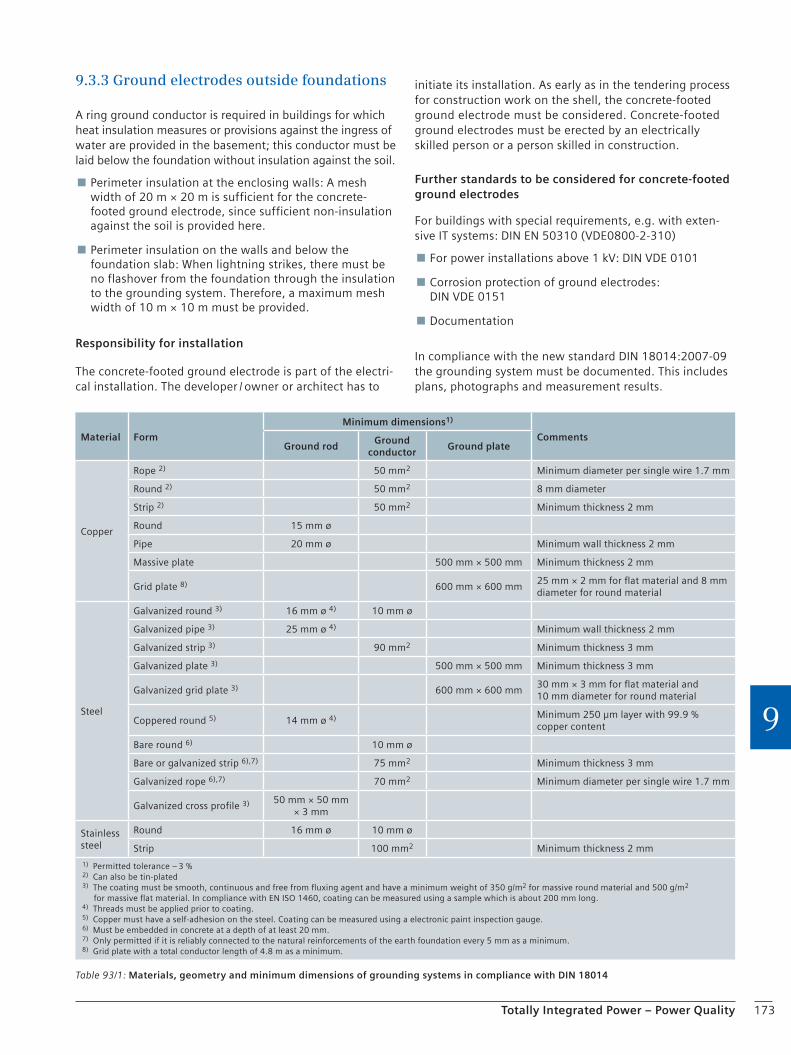
173Totally Integrated Power – Power Quality
9
9.3.3 Ground electrodes outside foundations
A ring ground conductor is required in buildings for which heat insulation measures or provisions against the ingress of water are provided in the basement; this conductor must be laid below the foundation without insulation against the soil.
Perimeter insulation at the enclosing walls: A mesh width of 20 m × 20 m is sufficient for the concrete-footed ground electrode, since sufficient non-insulation against the soil is provided here.
Perimeter insulation on the walls and below the foundation slab: When lightning strikes, there must be no flashover from the foundation through the insulation to the grounding system. Therefore, a maximum mesh width of 10 m × 10 m must be provided.
Responsibility for installation
The concrete-footed ground electrode is part of the electri-cal installation. The developer / owner or architect has to
initiate its installation. As early as in the tendering process for construction work on the shell, the concrete-footed ground electrode must be considered. Concrete-footed ground electrodes must be erected by an electrically skilled person or a person skilled in construction.
Further standards to be considered for concrete-footed ground electrodes
For buildings with special requirements, e.g. with exten-sive IT systems: DIN EN 50310 (VDE0800-2-310)
For power installations above 1 kV: DIN VDE 0101
Corrosion protection of ground electrodes: DIN VDE 0151
Documentation
In compliance with the new standard DIN 18014:2007-09 the grounding system must be documented. This includes plans, photographs and measurement results.
Table 93/1: Materials, geometry and minimum dimensions of grounding systems in compliance with DIN 18014
Material Form
Minimum dimensions1)
CommentsGround rod
Ground conductor
Ground plate
Copper
Rope 2) 50 mm2 Minimum diameter per single wire 1.7 mm
Round 2) 50 mm2 8 mm diameter
Strip 2) 50 mm2 Minimum thickness 2 mm
Round 15 mm ø
Pipe 20 mm ø Minimum wall thickness 2 mm
Massive plate 500 mm × 500 mm Minimum thickness 2 mm
Grid plate 8) 600 mm × 600 mm25 mm × 2 mm for flat material and 8 mm diameter for round material
Steel
Galvanized round 3) 16 mm ø 4) 10 mm ø
Galvanized pipe 3) 25 mm ø 4) Minimum wall thickness 2 mm
Galvanized strip 3) 90 mm2 Minimum thickness 3 mm
Galvanized plate 3) 500 mm × 500 mm Minimum thickness 3 mm
Galvanized grid plate 3) 600 mm × 600 mm30 mm × 3 mm for flat material and 10 mm diameter for round material
Coppered round 5) 14 mm ø 4) Minimum 250 μm layer with 99.9 % copper content
Bare round 6) 10 mm ø
Bare or galvanized strip 6),7) 75 mm2 Minimum thickness 3 mm
Galvanized rope 6),7) 70 mm2 Minimum diameter per single wire 1.7 mm
Galvanized cross profile 3) 50 mm × 50 mm × 3 mm
Stainless steel
Round 16 mm ø 10 mm ø
Strip 100 mm2 Minimum thickness 2 mm
1) Permitted tolerance – 3 %2) Can also be tin-plated3) The coating must be smooth, continuous and free from fluxing agent and have a minimum weight of 350 g/m2 for massive round material and 500 g/m2
for massive flat material. In compliance with EN ISO 1460, coating can be measured using a sample which is about 200 mm long.4) Threads must be applied prior to coating.5) Copper must have a self-adhesion on the steel. Coating can be measured using a electronic paint inspection gauge.6) Must be embedded in concrete at a depth of at least 20 mm.7) Only permitted if it is reliably connected to the natural reinforcements of the earth foundation every 5 mm as a minimum.8) Grid plate with a total conductor length of 4.8 m as a minimum.

174 Totally Integrated Power – Power Quality
9
9.4 Integration of Regenerative Energy SourcesThe growing awareness that fossil fuels are a limited resource in conjunction with the insight that their use is increasingly questionable from an ecological point of view has resulted in a growing importance of the integration of regenerative energy sources into the generation of elec-tricity in recent years.
In this context, regenerative energy sources or renewable energies mean sustainable energy sources or carriers which are not irretrievably consumed or run down or worked out during power generation (in contrast to fossil fuels), but renew themselves in a natural way within a foreseeable period of time without causing harmful effects on the climate. Renewable sources of energy are available in the following forms:
Sunlight / sun heat
Water power
Wind power
Biomass
Geothermy (earth heat)
According to the BDEW (German Federal Association of Energy and Water Management), around 48.9 billion kWh of electricity are already gained using regenerative ener-gies in Germany today (Fig. 94/1). With a share of 15 %, they thus take an important part in the primary energy budget in Germany. So far the greatest share in today's utilization of renewable energies have had wind power stations with around 45 % and water power with around 24 % (Fig. 94/2). There is a rising tendency.
The long-term objective is to replace conventional power generation using fossil fuels and nuclear energy by the use of renewable sources of energy. As energy quantities generated with regenerative energy sources like wind or sun energy are subject to great variations, on the one hand, and since there is only an insufficient storage tech-nology available on the other hand, these regenerative energy sources cannot yet be employed for providing a sTable basic power supply.
The integration of regenerative energies into a modern overall technological concept for a power system repre-sents a particular challenge. Today's interconnected grids are designed for transmitting electricity from a manage-able number of powerful power plants or refineries over long distances to the respective consumers (consumer installations).
The additional integration of numerous distributed power generators into the widely webbed interconnected grid takes up additional transmission capacities. Most of all the different performance classes of regenerative energy sources must be taken into consideration in this context, they may range from a few kilowatts to several megawatt. Even if the existing overhead lines can bear this additional load without any problems in normal operation, it can nevertheless reduce transmission reserves. In times with a high degree of system utilization or in the case of load shifts, disturbances might occur.
Total gross electricity generation in Germany in the first six months of 2008
Distribution in percent
Renewable energies
Nuclear energy
Coal, natural gas and other
in billion kWh;in brackets: difference to the first six months of 2007
Source: BDEW
48.9(+3.4)
74.9(–0.2)
202.3(+4.7)
62
15
23
Fig. 94/1: Distribution of the gross electricity generation to different power sources in the first six months of 2008
Sewage gas1.2 %
Sanitary landfill gas1.2 %
Water power23.7 %
Photovoltaics4 %
Biomass24.8 %
Wind power45.1 %
Source: Wikipedia
Fig. 94/2: Wind power stations and water power have the greatest share in today's exploitation of renewable energies
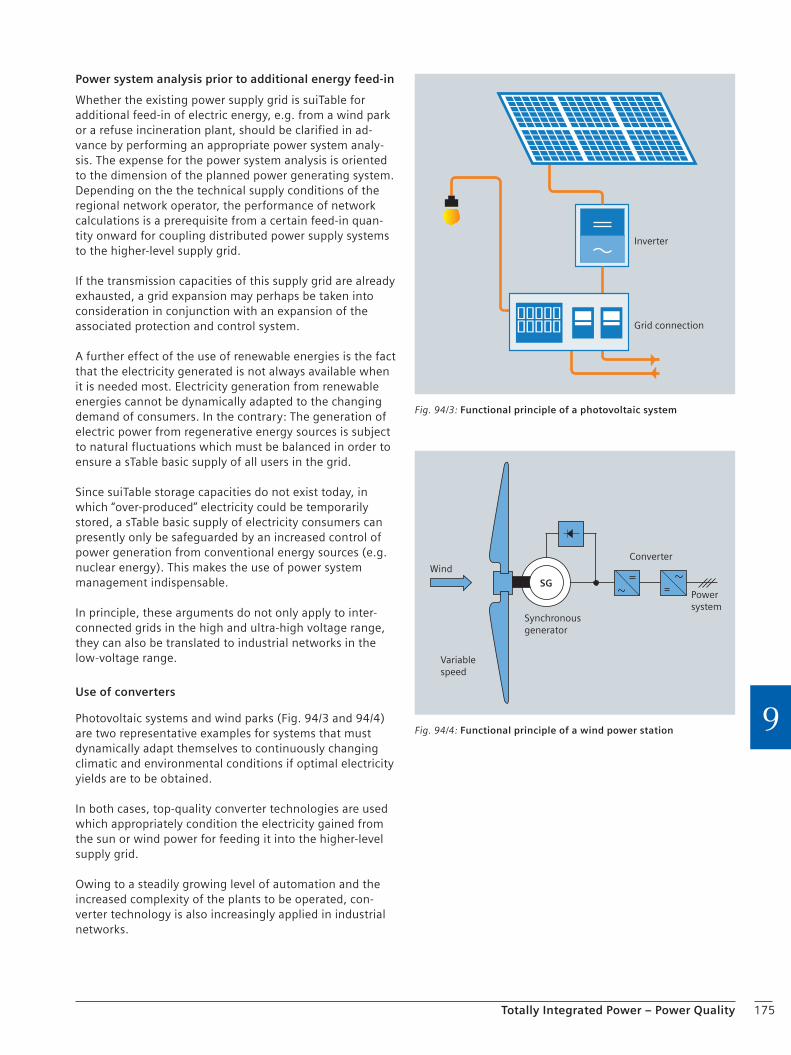
175Totally Integrated Power – Power Quality
9
Power system analysis prior to additional energy feed-in
Whether the existing power supply grid is suiTable for additional feed-in of electric energy, e.g. from a wind park or a refuse incineration plant, should be clarified in ad-vance by performing an appropriate power system analy-sis. The expense for the power system analysis is oriented to the dimension of the planned power generating system. Depending on the the technical supply conditions of the regional network operator, the performance of network calculations is a prerequisite from a certain feed-in quan-tity onward for coupling distributed power supply systems to the higher-level supply grid.
If the transmission capacities of this supply grid are already exhausted, a grid expansion may perhaps be taken into consideration in conjunction with an expansion of the associated protection and control system.
A further effect of the use of renewable energies is the fact that the electricity generated is not always available when it is needed most. Electricity generation from renewable energies cannot be dynamically adapted to the changing demand of consumers. In the contrary: The generation of electric power from regenerative energy sources is subject to natural fluctuations which must be balanced in order to ensure a sTable basic supply of all users in the grid.
Since suiTable storage capacities do not exist today, in which “over-produced” electricity could be temporarily stored, a sTable basic supply of electricity consumers can presently only be safeguarded by an increased control of power generation from conventional energy sources (e.g. nuclear energy). This makes the use of power system management indispensable.
In principle, these arguments do not only apply to inter-connected grids in the high and ultra-high voltage range, they can also be translated to industrial networks in the low-voltage range.
Use of converters
Photovoltaic systems and wind parks (Fig. 94/3 and 94/4) are two representative examples for systems that must dynamically adapt themselves to continuously changing climatic and environmental conditions if optimal electricity yields are to be obtained.
In both cases, top-quality converter technologies are used which appropriately condition the electricity gained from the sun or wind power for feeding it into the higher-level supply grid.
Owing to a steadily growing level of automation and the increased complexity of the plants to be operated, con-verter technology is also increasingly applied in industrial networks.
Inverter
Grid connection
Fig. 94/3: Functional principle of a photovoltaic system
Converter
Synchronous generator
Variable speed
Wind
SGPower system
Fig. 94/4: Functional principle of a wind power station
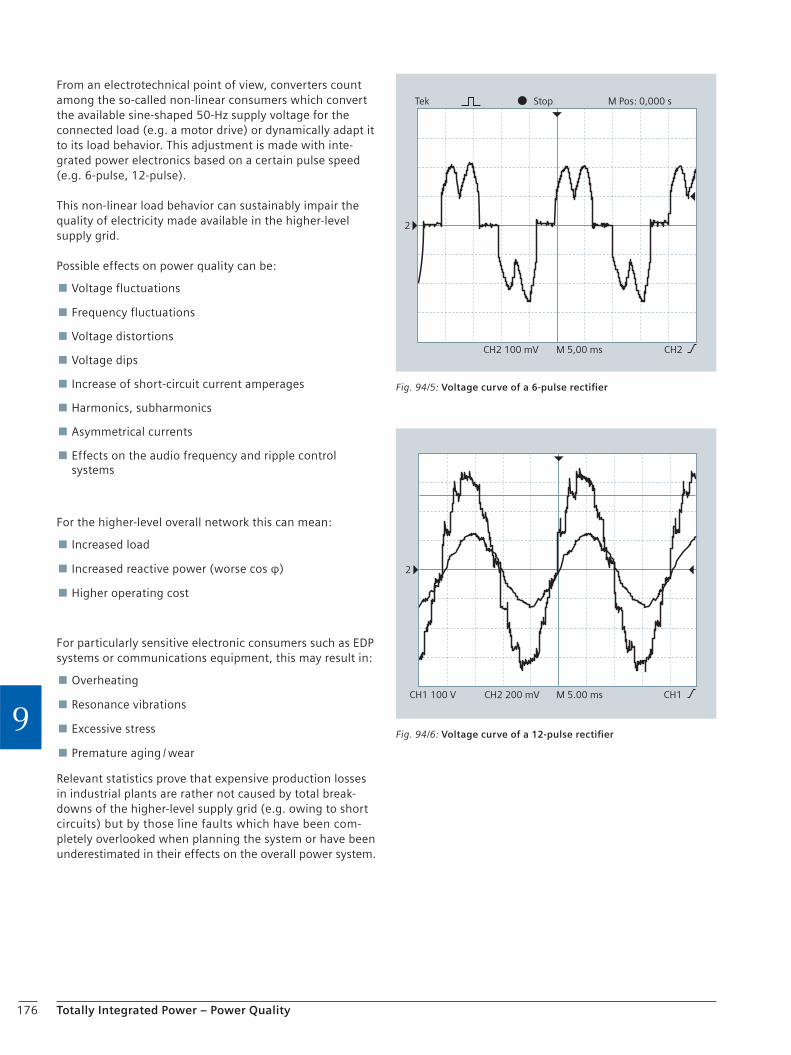
176 Totally Integrated Power – Power Quality
9
From an electrotechnical point of view, converters count among the so-called non-linear consumers which convert the available sine-shaped 50-Hz supply voltage for the connected load (e.g. a motor drive) or dynamically adapt it to its load behavior. This adjustment is made with inte-grated power electronics based on a certain pulse speed (e.g. 6-pulse, 12-pulse).
This non-linear load behavior can sustainably impair the quality of electricity made available in the higher-level supply grid.
Possible effects on power quality can be:
Voltage fluctuations
Frequency fluctuations
Voltage distortions
Voltage dips
Increase of short-circuit current amperages
Harmonics, subharmonics
Asymmetrical currents
Effects on the audio frequency and ripple control systems
For the higher-level overall network this can mean:
Increased load
Increased reactive power (worse cos φ)
Higher operating cost
For particularly sensitive electronic consumers such as EDP systems or communications equipment, this may result in:
Overheating
Resonance vibrations
Excessive stress
Premature aging / wear
Relevant statistics prove that expensive production losses in industrial plants are rather not caused by total break-downs of the higher-level supply grid (e.g. owing to short circuits) but by those line faults which have been com-pletely overlooked when planning the system or have been underestimated in their effects on the overall power system.
2
StopTek M Pos: 0,000 s
CH2 100 mV M 5,00 ms CH2
Fig. 94/5: Voltage curve of a 6-pulse rectifier
2
CH1 100 V CH2 200 mV M 5.00 ms CH1
Fig. 94/6: Voltage curve of a 12-pulse rectifier

177Totally Integrated Power – Power Quality
9
Line faults
Provided that they are well matched, the integration of regenerative power generators using converter technology can, however, have a quite positive effect on the power quality of the higher-level power system, since a possibly bad system cos φ can be improved when using sufficiently intelligent, flexible converter control (IGBT technology).
The converter quality is as essential for this as it is impor-tant for the efficiency, or respectively the best possible electricity yield, of the power generating system itself.
A further aspect of connecting distributed power generat-ing systems through converter technology is the problem of a voltage rise, when several distributed power generat-ing systems want to simultaneously feed the generated current into the higher-level grid (in parallel) – in the most unfavorable case even via a common feed-in point which is only partly designed for this temporary peak load.
In an unfavorable case, the converters of the respective power generating system will even work against each other – the current generated cannot be supplied, the electricity yield is reduced.
A further focus should be on the correct dimensioning of a suiTable overcurrent protection system for the feeder cable to the converter of the power generator which is to be protected against overload and short circuit in compliance with DIN VDE 0100 Part 430 or IEC 60364-4-43.
The use of a simple disconnecting device at the feed-in point is not sufficient for this purpose, as in the event of a short circuit, a fault current can be fed onto this cable both from the distributed power generating system and from the supply grid.
Despite all these imponderabilities, the use of regenera-tive energies bears a high potential in principle and will decisively shape the energy mix on the world market until 2100 according to a current forecast of the Scientific Advisory Committee of the German Federal Government.
Therefore, the challenges involved must be met.
When well thought out under planning aspects, the inte-gration of regenerative power generating systems into an existing supply grid can be extremely valuable for all parties involved:
For the supply network operator:
because – in conjunction with an intelligent network management system – it contributes to relieving conventional power generators (power plants) without producing supply bottlenecks
because the additional availability of electricity principally counteracts the risk of area-wide breakdowns in the interconnected grid and because additional redundancies are created
because the generation of reactive power can be reduced, which places a burden on the transmission capacity of the whole network and results in higher power losses, both of which yields no economic benefit
For the operators of a regenerative power generating system:
because the system, when set to its optimal power efficiency, can contribute to producing the greatest possible electricity yield without any trouble
For industrial plants and households:
because economic damage resulting from a total breakdown of the electric supply grid can be eliminated
because the power quality required for production can be maintained or respectively optimized, which helps to avoid premature damage at complex plants installations or quality losses in production and thus economic losses
because a stronger integration of these alternative power generating systems will bring about a liberalization of the electricity market which will make the use of electricity attractive and payable for everybody
For our environment:
because emissions can be sustainably reduced this way without that we would have to accept losing our accustomed standard of living
because CO2 emissions can be reduced this way, which is, as we all know, also responsible for the global climate change
because the extraction of fossil fuels for power generation is reduced
The prerequisite for this is the integrated planning of all components and the application of a holistic planning approach.
The expert teams of “Totally Integrated Power” provide technical support for specific power distribution projects and advice for the associated concepts.
178 Totally Integrated Power – Power Quality
9
Overview of power connection guidelines
Planning, erection, operation, change
VDEW guideline: In-plant power generators in the low-volt-age network, basics of planning and decision-making aid for supply network operators and installation companies: calculation examples for connection assessment:
Combined heat and power plants
Photovoltaic systems
Hydroelectric power plants
Wind power stations
Elimination of additional power system disturbances owing to faults
Niederspannungsanschlussverordnung (NAV) (Low-voltage Connection Ordinance)
VDN guideline: TAB Niederspannungsnetz, 2007 (Technical Supply Condition for the Low-voltage Network, 2007)
BDEW guideline: TAB Mittelspannungsnetz, 2008 (Technical Supply Condition for the Medium-voltage Network, 2008)
Generation and voltage stabilization in the power system
Ordinance on EEG 2009 (to be expected)
EN 50160: Characteristics of supply voltage
EN 50438: Small generators in the low-voltage network
VDN guideline: Transmission Code 2007: Network and System Rules of the German Transmission Network Operators
VDN guideline: Distribution Code 2007: Rules for the Access to Distribution Networks
VDN guideline: Erzeugungsanlagen im Hochspannungsnetz (Generating systems in the high-voltage network)
BDEW guideline: Erzeugungsanlagen im Mittelspannungsnetz 2008 (Generating systems in the medium-voltage network 2008)
BDEW guideline: Erzeugungsanlagen im Niederspannungsnetz (Generating systems in the low-voltage network) (in preparation)
VDN guideline: Beurteilung von Netzrückwirkungen (Evaluation of system perturbations)
Chapter 10Lighting
10.1 Lighting of Indoor Workplaces 180
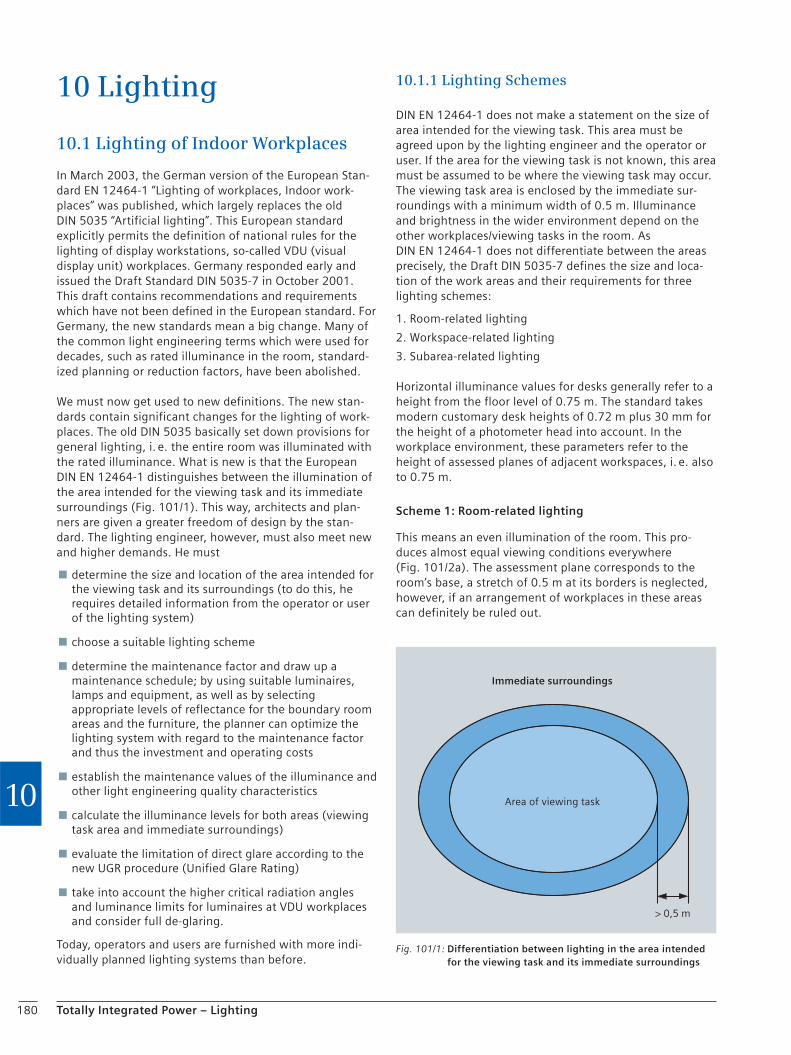
180 Totally Integrated Power – Lighting
10
10 Lighting
10.1 Lighting of Indoor Workplaces
In March 2003, the German version of the European Stan-dard EN 12464-1 “Lighting of workplaces, Indoor work-places” was published, which largely replaces the old DIN 5035 “Artificial lighting”. This European standard explicitly permits the definition of national rules for the lighting of display workstations, so-called VDU (visual display unit) workplaces. Germany responded early and issued the Draft Standard DIN 5035-7 in October 2001. This draft contains recommendations and requirements which have not been defined in the European standard. For Germany, the new standards mean a big change. Many of the common light engineering terms which were used for decades, such as rated illuminance in the room, standard-ized planning or reduction factors, have been abolished.
We must now get used to new definitions. The new stan-dards contain significant changes for the lighting of work-places. The old DIN 5035 basically set down provisions for general lighting, i. e. the entire room was illuminated with the rated illuminance. What is new is that the European DIN EN 12464-1 distinguishes between the illumination of the area intended for the viewing task and its immediate surroundings (Fig. 101/1). This way, architects and plan-ners are given a greater freedom of design by the stan-dard. The lighting engineer, however, must also meet new and higher demands. He must
determine the size and location of the area intended for the viewing task and its surroundings (to do this, he requires detailed information from the operator or user of the lighting system)
choose a suitable lighting scheme
determine the maintenance factor and draw up a maintenance schedule; by using suitable luminaires, lamps and equipment, as well as by selecting appropriate levels of reflectance for the boundary room areas and the furniture, the planner can optimize the lighting system with regard to the maintenance factor and thus the investment and operating costs
establish the maintenance values of the illuminance and other light engineering quality characteristics
calculate the illuminance levels for both areas (viewing task area and immediate surroundings)
evaluate the limitation of direct glare according to the new UGR procedure (Unified Glare Rating)
take into account the higher critical radiation angles and luminance limits for luminaires at VDU workplaces and consider full de-glaring.
Today, operators and users are furnished with more indi-vidually planned lighting systems than before.
10.1.1 Lighting Schemes
DIN EN 12464-1 does not make a statement on the size of area intended for the viewing task. This area must be agreed upon by the lighting engineer and the operator or user. If the area for the viewing task is not known, this area must be assumed to be where the viewing task may occur. The viewing task area is enclosed by the immediate sur-roundings with a minimum width of 0.5 m. Illuminance and brightness in the wider environment depend on the other workplaces/viewing tasks in the room. As DIN EN 12464-1 does not differentiate between the areas precisely, the Draft DIN 5035-7 defines the size and loca-tion of the work areas and their requirements for three lighting schemes:
1. Room-related lighting
2. Workspace-related lighting
3. Subarea-related lighting
Horizontal illuminance values for desks generally refer to a height from the floor level of 0.75 m. The standard takes modern customary desk heights of 0.72 m plus 30 mm for the height of a photometer head into account. In the workplace environment, these parameters refer to the height of assessed planes of adjacent workspaces, i. e. also to 0.75 m.
Scheme 1: Room-related lighting
This means an even illumination of the room. This pro-duces almost equal viewing conditions everywhere (Fig. 101/2a). The assessment plane corresponds to the room’s base, a stretch of 0.5 m at its borders is neglected, however, if an arrangement of workplaces in these areas can definitely be ruled out.
Fig. 101/1: Differentiation between lighting in the area intended for the viewing task and its immediate surroundings
Immediate surroundings
Area of viewing task
> 0,5 m

181Totally Integrated Power – Lighting
10
The “room-related lighting” scheme provides many advan-tages when
the same viewing conditions are required in the entire room
the workspace allocations and their spatial extensions are not known during planning
VDU workplaces are to be variably arranged
the same illumination effect is to be created in the entire room.
Scheme 2: Workspace-related lighting
In this concept, the workspaces and ambient areas are lit separately (Fig. 101/2b).
In office rooms, we distinguish between workspaces for VDU work, meeting, and reading at cabinet or shelf areas. Please note that the standard defines the term “workspace” in a very broad sense which is not confined merely to the actual desk or conference table. It also includes areas on which working aids necessary for the due course of the work have been arranged, as well as the minimum areas the user needs for the functional and proper execution of his/her task. User areas at the desk have a minimum depth of 1.00 m, while for visitor and meeting spaces, a depth of 0.80 m is sufficient. Due to the fact that the workspace also includes the user area, viewing tasks which are carried out in a leaned-back seating or standing work position are considered as well. Dynamic seating which varies between a forward, medium and leaned-back seating position as well as occasional standing is of great importance for ergonomic working conditions.
The “workspace-related lighting” scheme provides many advantages when
the tasks, workplaces and thus the workspaces are known
workplaces are intended for different tasks which require differentiated lighting conditions.
Different brightness levels in the individual workspaces and their ambient areas create light zones which may positively influence the atmosphere of the room. When planning lighting systems, special emphasis must however be placed on well balanced luminance conditions in the room.
Scheme 3: Subarea-related lighting
In this concept, subareas within the workspaces are lit separately (Fig. 101/2c).
The illuminance of this subarea shall be substantially higher than that of the work area and a soft transition between the areas must be ensured. This concept can be implemented by using workspace lamps in compliance with DIN 5035-8.
The “subarea-related lighting” scheme provides many advantages when
it is necessary to adapt the illumination of the workspace to different activities or viewing tasks
difficult viewing tasks are to be performed
the lighting must be adjustable to the individual eyesight and other needs of the user
individual adjustment of the lighting conditions is desired.
The focus on a subarea within the workspace is enhanced by using an increased illuminance.
The draft standard for VDU workplaces also contains de-tailed specifications of vertical illuminances for reading file labels and text on book spines in filing cabinets and shelves and for cylindrical illuminances for recognizing faces, facial expressions and gestures as a prerequisite for good visual communication.
Fig. 101/2: (a) room-related, (b) workspace-related and (c) subarea-related lighting scheme
Cabinet and shelf areas Ambient areaVDU workMeeting area Subarea for viewing task600 mm x 600 mm; Eh,m = 750 lx
E = 500 lx
0,5 m
0,8
m
E = 500 lxE = 500 lx
E = 300 lx
0,8
m
E = 500 lxE = 500 lx
E = 300 lx 0,5 m
a) b) c)
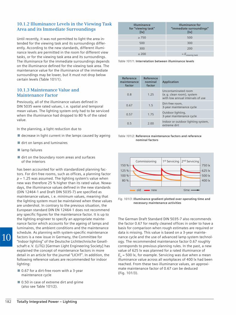
182 Totally Integrated Power – Lighting
10
10.1.2 Illuminance Levels in the Viewing Task Area and its Immediate Surroundings
Until recently, it was not permitted to light the area in-tended for the viewing task and its surroundings differ-ently. According to the new standards, different illumi-nance levels are permitted in the room for different view tasks, or for the viewing task area and its surroundings. The illuminance for the immediate surroundings depends on the illuminance defined for the viewing task area. The maintenance value for the illuminance of the immediate surroundings may be lower, but it must not drop below certain levels (Table 101/1).
10.1.3 Maintenance Value and Maintenance Factor
Previously, all of the illuminance values defined in DIN 5035 were rated values, i. e. spatial and temporal mean values. The lighting system only had to be serviced when the illuminance had dropped to 80 % of the rated value.
In the planning, a light reduction due to
decrease in light current in the lamps caused by ageing
dirt on lamps and luminaires
lamp failures
dirt on the boundary room areas and surfaces of the interiors
has been accounted for with standardized planning fac-tors. For dirt-free rooms, such as offices, a planning factor p = 1.25 was assumed. The lighting system’s value when new was therefore 25 % higher than its rated value. Nowa-days, the illuminance values defined in the new standards (DIN 12464-1 and Draft DIN 5035-7) are specified as maintenance values, i. e. minimum values, meaning that the lighting system must be maintained when these values are undershot. In contrary to the previous situation, the European standard DIN EN 12464-1 does not recommend any specific figures for the maintenance factor. It is up to the lighting engineer to specify an appropriate mainte-nance factor which accounts for the ageing of lamps and luminaires, the ambient conditions and the maintenance schedule. As planning with system-specific maintenance factors is a new issue in Germany, the Committee for “Indoor lighting” of the Deutsche Lichttechnische Gesell-schaft e. V. (LiTG) [German Light Engineering Society] has explained the concept of maintenance factors in more detail in an article for the journal “LICHT”. In addition, the following reference values are recommended for indoor lighting:
0.67 for a dirt-free room with a 3-year maintenance cycle
0.50 in case of extreme dirt and grime (also see Table 101/2).
The German Draft Standard DIN 5035-7 also recommends the factor 0.67 for neatly cleaned offices in order to have a basis for comparison when rough estimates are required or data is missing. This value is based on a 3-year mainte-nance cycle and the use of advanced lamp system technol-ogy. The recommended maintenance factor 0.67 roughly corresponds to previous planning rules. In the past, a new value of 625 lx was planned for a rated illuminance of En = 500 lx, for example. Servicing was due when a mean illuminance value across all workplaces of 400 lx had been reached. From these two illuminance values, an approxi-mate maintenance factor of 0.67 can be deduced (Fig. 101/3).
Commissioning 1st Servicing 2nd Servicing
timeold new
150 %
125 %
100 %
80 %
750 lx
625 lx
500 lx
400 lx
Fig. 101/3: Illuminance gradient plotted over operating time and necessary maintenance activities
Table 101/1: Interrelation between illuminance levels
Illuminance for “viewing task”
[lx]
Illuminance for “immediate surroundings”
[lx]
≥ 750 500
500 300
300 200
≤ 200 = Eviewing task
Table 101/2: Reference maintenance factors and reference nominal factors
Reference maintenance
factor
Reference nominal
factorApplication
0.8 1.25Uncontaminated room (e. g. clean room), system with low annual intervals of use
0.67 1.5Dirt-free room, 3-year maintenance cycle
0.57 1.75Outdoor lighting, 3-year maintenance cycle
0.5 2.00Indoor or outdoor lighting system, extreme dirt
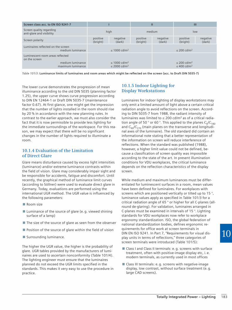
183Totally Integrated Power – Lighting
10
The lower curve demonstrates the progression of mean illuminance according to the old DIN 5035 (planning factor 1.25), the upper curve shows curve progression according to DIN EN 12464-1 or Draft DIN 5035-7 (maintenance factor 0.67). At first glance, one might get the impression that the number of lights installed in the room should rise by 20 % in accordance with the new planning rules. In contrast to the earlier approach, we must also consider the fact that it is now permissible to provide less lighting for the immediate surroundings of the workspace. For this rea-son, we may expect that there will be no significant changes in the number of lights required to illuminate a room.
10.1.4 Evaluation of the Limitation of Direct Glare
Glare means disturbance caused by excess light intensities (luminance) and/or extreme luminance contrasts within the field of vision. Glare may considerably impair sight and be responsible for accidents, fatigue and discomfort. Until recently, the graphical method of luminance limit curves (according to Söllner) were used to evaluate direct glare in Germany. Today, evaluations are performed using the international UGR method. The UGR value is influenced by the following parameters:
Room size
Luminance of the source of glare (e. g. viewed shining surface of a lamp)
The size of the source of glare as seen from the observer
Position of the source of glare within the field of vision
Surrounding luminance.
The higher the UGR value, the higher is the probability of glare. UGR tables provided by the manufacturers of lumi-naires are used to ascertain nonconformity (Table 101/4). The lighting engineer must ensure that the luminaires planned do not exceed the UGR limits specified in the standards. This makes it very easy to use the procedure in practice.
10.1.5 Indoor Lighting for Display Workstations
Luminaires for indoor lighting of display workstations may only emit a limited amount of light above a certain critical radiation angle to avoid reflections on the screen. Accord-ing to DIN 5035-7 from 1988, the radiant intensity of luminaires was limited to ≤ 200 cd/m2 as of a critical radia-tion angle of 50 ° or 60 °. This applied to the planes C0/C180 and C90/C270 (main planes on the transverse and longitudi-nal axes of the luminaire). The old standard did contain an informational note stating that a better representation of the information on screen will reduce interference of reflections. When the standard was published (1988), however, a higher limit value could not be defined, be-cause a classification of screen quality was impossible according to the state of the art. In present illumination conditions for VDU workplaces, the critical luminance depends on the reflection characteristics of the display screen.
While medium and maximum luminances must be differ-entiated for luminescent surfaces in a room, mean values have been defined for luminaires. For workplaces with screens which are positioned vertically or tilted up to 15 °, luminance values apply as specified in Table 101/3 for a critical radiation angle of 65 ° or higher for all C-planes (all-round de-glaring). For validation, luminaires arranged in C-planes must be examined in intervals of 15 °. Lighting standards for VDU workplaces now refer to workplace ergonomy standardization. ISO, the global federation of national standardization bodies, defines ergonomic re-quirements for office work at screen terminals in DIN EN ISO 9241. In Part 7, “Requirements for visual dis-play units in terms of reflections,” three categories of screen terminals were introduced (Table 101/5):
Class I and Class II terminals: e. g. screens with surface treatment, often with positive-image display etc, i. e. modern terminals, as currently used in most offices
Class III terminals: e. g. screens with negative-image display, low contrast, without surface treatment (e. g. large CAD screens).
Table 101/3: Luminance limits of luminaires and room areas which might be reflected on the screen (acc. to Draft DIN 5035-7)
Screen class acc. to EN ISO 9241-7 I II III
Screen quality regarding anti-glare and visibility
high medium low
Screen polaritypositive (bright)
negative (dark)
positive (bright)
negative (dark)
positive (bright)
negative (dark)
Luminaires reflected on the screenmedium luminance
≤ 1000 cd/m2
≤ 200 cd/m2
Luminescent room areas reflected on the screen
medium luminancemaximum luminance
≤ 1000 cd/m2 ≤ 2000 cd/m2
≤ 200 cd/m2 ≤ 400 cd/m2
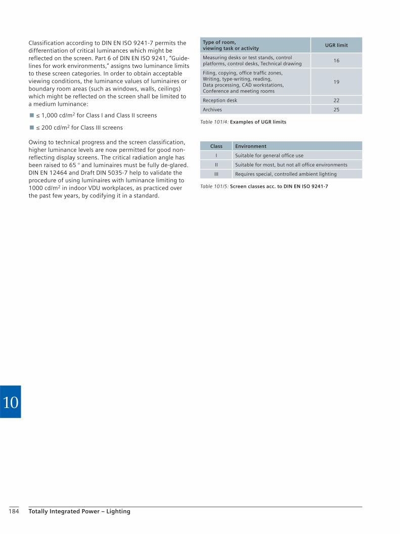
184 Totally Integrated Power – Lighting
10
Classification according to DIN EN ISO 9241-7 permits the differentiation of critical luminances which might be reflected on the screen. Part 6 of DIN EN ISO 9241, “Guide-lines for work environments,” assigns two luminance limits to these screen categories. In order to obtain acceptable viewing conditions, the luminance values of luminaires or boundary room areas (such as windows, walls, ceilings) which might be reflected on the screen shall be limited to a medium luminance:
≤ 1,000 cd/m2 for Class I and Class II screens
≤ 200 cd/m2 for Class III screens
Owing to technical progress and the screen classification, higher luminance levels are now permitted for good non-reflecting display screens. The critical radiation angle has been raised to 65 ° and luminaires must be fully de-glared. DIN EN 12464 and Draft DIN 5035-7 help to validate the procedure of using luminaires with luminance limiting to 1000 cd/m2 in indoor VDU workplaces, as practiced over the past few years, by codifying it in a standard.
Table 101/4: Examples of UGR limits
Type of room, viewing task or activity
UGR limit
Measuring desks or test stands, control platforms, control desks, Technical drawing
16
Filing, copying, office traffic zones, Writing, type-writing, reading, Data processing, CAD workstations, Conference and meeting rooms
19
Reception desk 22
Archives 25
Table 101/5: Screen classes acc. to DIN EN ISO 9241-7
Class Environment
I Suitable for general office use
II Suitable for most, but not all office environments
III Requires special, controlled ambient lighting

Chapter 11Energy-efficient Buildings
11.1 The Energy Certificate for Buildings 186
11.2 Effects of Building Automation Systems on the Energy Efficiency of Buildings 188
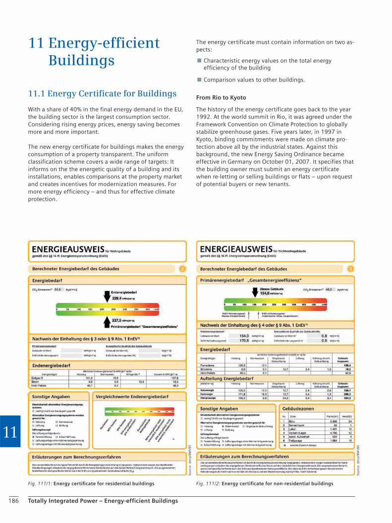
186 Totally Integrated Power – Energy-efficient Buildings
11
11 Energy-efficient Buildings
11.1 Energy Certificate for Buildings
With a share of 40% in the final energy demand in the EU, the building sector is the largest consumption sector. Considering rising energy prices, energy saving becomes more and more important.
The new energy certificate for buildings makes the energy consumption of a property transparent. The uniform classification scheme covers a wide range of targets: It informs on the the energetic quality of a building and its installations, enables comparisons at the property market and creates incentives for modernization measures. For more energy efficiency – and thus for effective climate protection.
The energy certificate must contain information on two as-pects:
Characteristic energy values on the total energy efficiency of the building
Comparison values to other buildings.
From Rio to Kyoto
The history of the energy certificate goes back to the year 1992. At the world summit in Rio, it was agreed under the Framework Convention on Climate Protection to globally stabilize greenhouse gases. Five years later, in 1997 in Kyoto, binding commitments were made on climate pro-tection above all by the industrial states. Against this background, the new Energy Saving Ordinance became effective in Germany on October 01, 2007. It specifies that the building owner must submit an energy certificate when re-letting or selling buildings or flats – upon request of potential buyers or new tenants.
Fig. 111/1: Energy certificate for residential buildings Fig. 111/2: Energy certificate for non-residential buildings
Sou
rce:
den
a/BM
VBS
Sou
rce:
den
a/BM
VBS
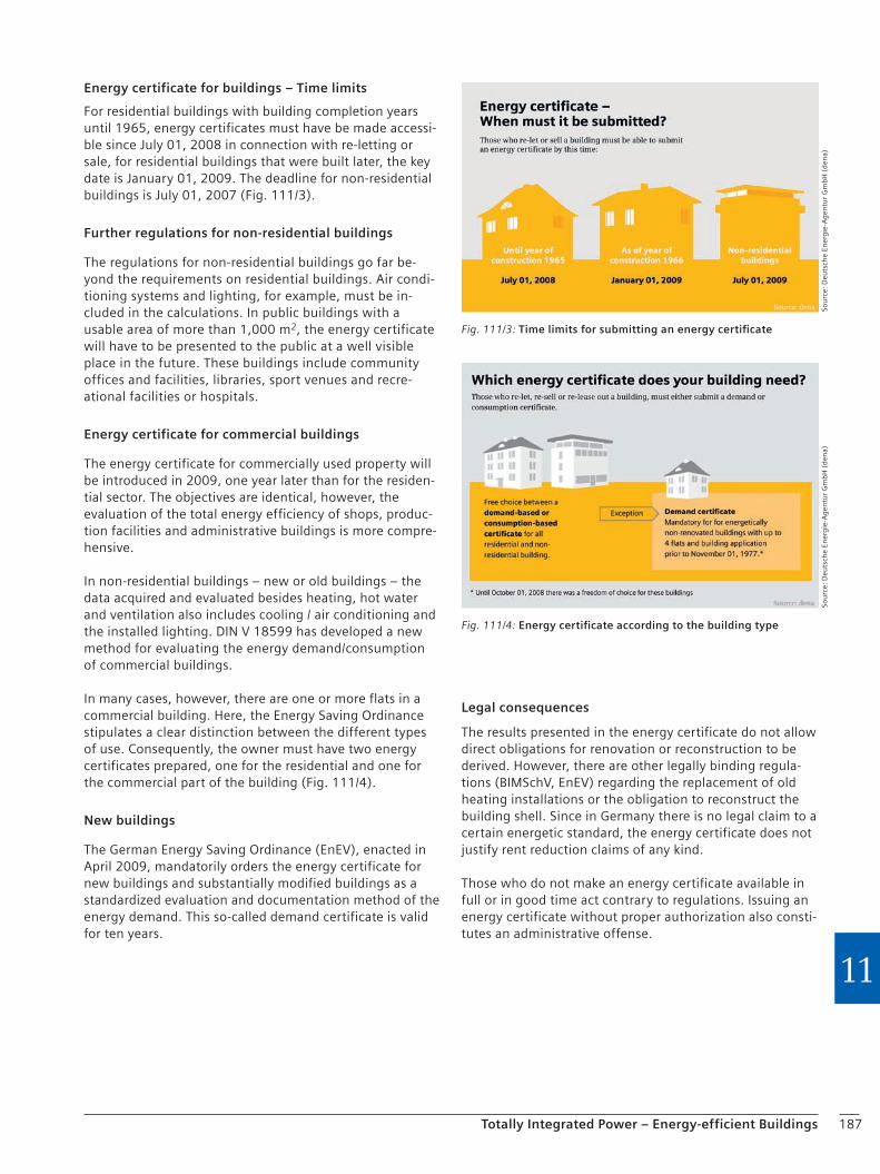
187Totally Integrated Power – Energy-efficient Buildings
11
Energy certificate for buildings – Time limits
For residential buildings with building completion years until 1965, energy certificates must have be made accessi-ble since July 01, 2008 in connection with re-letting or sale, for residential buildings that were built later, the key date is January 01, 2009. The deadline for non-residential buildings is July 01, 2007 (Fig. 111/3).
Further regulations for non-residential buildings
The regulations for non-residential buildings go far be-yond the requirements on residential buildings. Air condi-tioning systems and lighting, for example, must be in-cluded in the calculations. In public buildings with a usable area of more than 1,000 m2, the energy certificate will have to be presented to the public at a well visible place in the future. These buildings include community offices and facilities, libraries, sport venues and recre-ational facilities or hospitals.
Energy certificate for commercial buildings
The energy certificate for commercially used property will be introduced in 2009, one year later than for the residen-tial sector. The objectives are identical, however, the evaluation of the total energy efficiency of shops, produc-tion facilities and administrative buildings is more compre-hensive.
In non-residential buildings – new or old buildings – the data acquired and evaluated besides heating, hot water and ventilation also includes cooling / air conditioning and the installed lighting. DIN V 18599 has developed a new method for evaluating the energy demand/consumption of commercial buildings.
In many cases, however, there are one or more flats in a commercial building. Here, the Energy Saving Ordinance stipulates a clear distinction between the different types of use. Consequently, the owner must have two energy certificates prepared, one for the residential and one for the commercial part of the building (Fig. 111/4).
New buildings
The German Energy Saving Ordinance (EnEV), enacted in April 2009, mandatorily orders the energy certificate for new buildings and substantially modified buildings as a standardized evaluation and documentation method of the energy demand. This so-called demand certificate is valid for ten years.
Sou
rce:
Deu
tsch
e En
erg
ie-A
gen
tur
Gm
bH
(d
ena)
Sou
rce:
Deu
tsch
e En
erg
ie-A
gen
tur
Gm
bH
(d
ena)
Legal consequences
The results presented in the energy certificate do not allow direct obligations for renovation or reconstruction to be derived. However, there are other legally binding regula-tions (BIMSchV, EnEV) regarding the replacement of old heating installations or the obligation to reconstruct the building shell. Since in Germany there is no legal claim to a certain energetic standard, the energy certificate does not justify rent reduction claims of any kind.
Those who do not make an energy certificate available in full or in good time act contrary to regulations. Issuing an energy certificate without proper authorization also consti-tutes an administrative offense.
Fig. 111/3: Time limits for submitting an energy certificate
Fig. 111/4: Energy certificate according to the building type
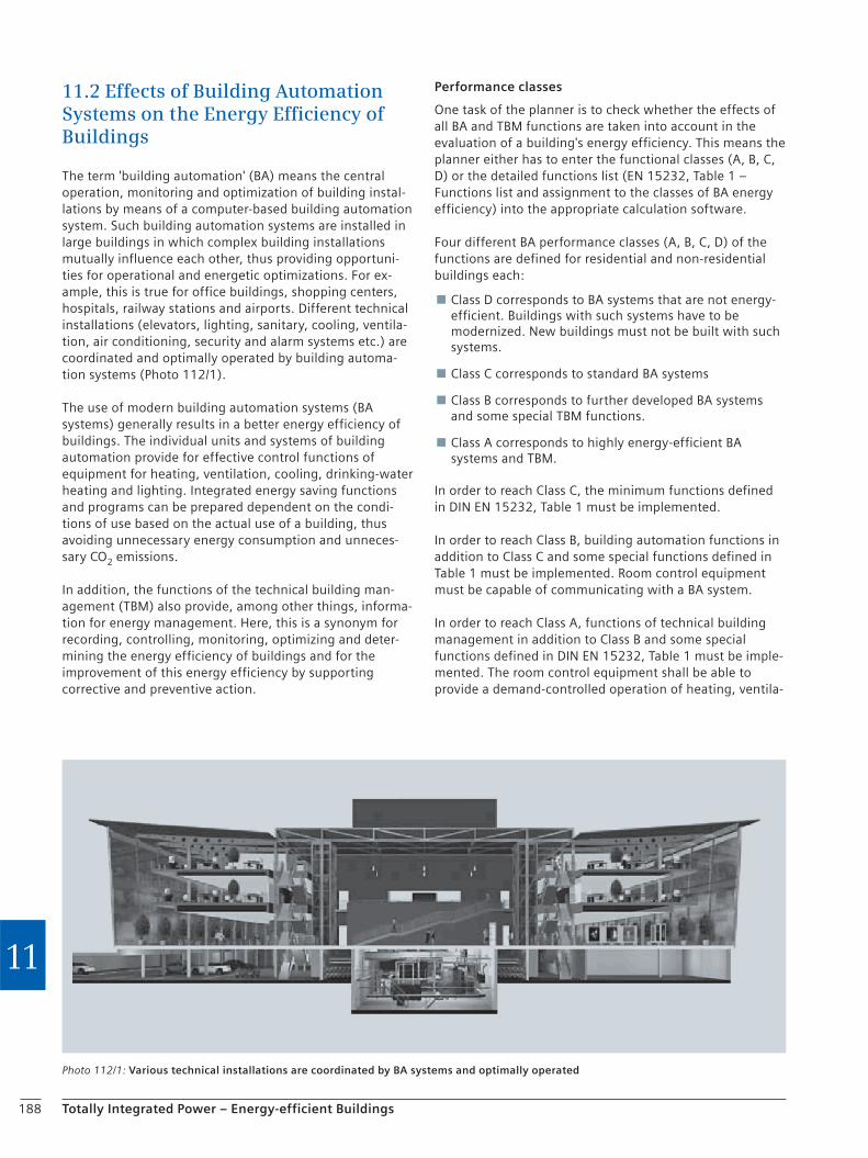
188 Totally Integrated Power – Energy-efficient Buildings
11
11.2 Effects of Building Automation Systems on the Energy Efficiency of Buildings
The term 'building automation' (BA) means the central operation, monitoring and optimization of building instal-lations by means of a computer-based building automation system. Such building automation systems are installed in large buildings in which complex building installations mutually influence each other, thus providing opportuni-ties for operational and energetic optimizations. For ex-ample, this is true for office buildings, shopping centers, hospitals, railway stations and airports. Different technical installations (elevators, lighting, sanitary, cooling, ventila-tion, air conditioning, security and alarm systems etc.) are coordinated and optimally operated by building automa-tion systems (Photo 112/1).
The use of modern building automation systems (BA systems) generally results in a better energy efficiency of buildings. The individual units and systems of building automation provide for effective control functions of equipment for heating, ventilation, cooling, drinking-water heating and lighting. Integrated energy saving functions and programs can be prepared dependent on the condi-tions of use based on the actual use of a building, thus avoiding unnecessary energy consumption and unneces-sary CO2 emissions.
In addition, the functions of the technical building man-agement (TBM) also provide, among other things, informa-tion for energy management. Here, this is a synonym for recording, controlling, monitoring, optimizing and deter-mining the energy efficiency of buildings and for the improvement of this energy efficiency by supporting corrective and preventive action.
Performance classes
One task of the planner is to check whether the effects of all BA and TBM functions are taken into account in the evaluation of a building's energy efficiency. This means the planner either has to enter the functional classes (A, B, C, D) or the detailed functions list (EN 15232, Table 1 – Functions list and assignment to the classes of BA energy efficiency) into the appropriate calculation software.
Four different BA performance classes (A, B, C, D) of the functions are defined for residential and non-residential buildings each:
Class D corresponds to BA systems that are not energy-efficient. Buildings with such systems have to be modernized. New buildings must not be built with such systems.
Class C corresponds to standard BA systems
Class B corresponds to further developed BA systems and some special TBM functions.
Class A corresponds to highly energy-efficient BA systems and TBM.
In order to reach Class C, the minimum functions defined in DIN EN 15232, Table 1 must be implemented.
In order to reach Class B, building automation functions in addition to Class C and some special functions defined in Table 1 must be implemented. Room control equipment must be capable of communicating with a BA system.
In order to reach Class A, functions of technical building management in addition to Class B and some special functions defined in DIN EN 15232, Table 1 must be imple-mented. The room control equipment shall be able to provide a demand-controlled operation of heating, ventila-
Photo 112/1: Various technical installations are coordinated by BA systems and optimally operated
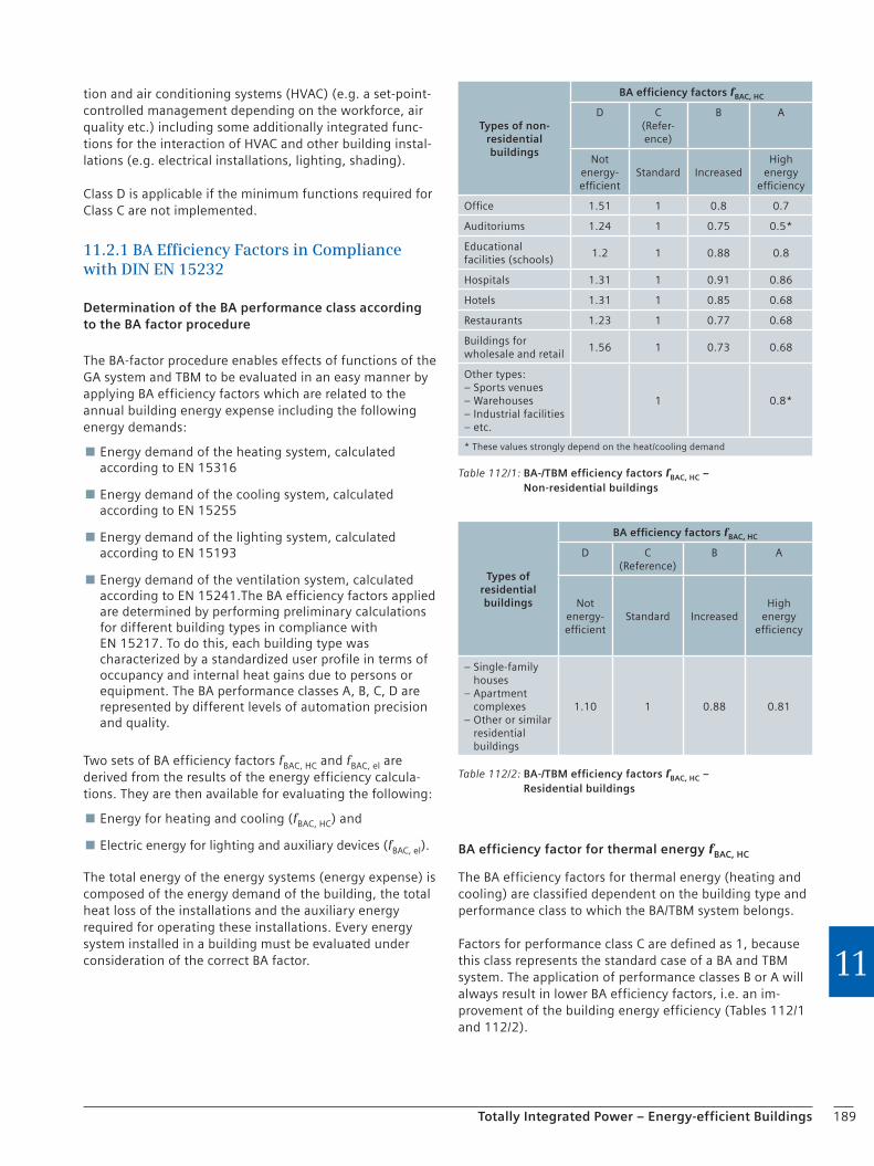
189Totally Integrated Power – Energy-efficient Buildings
11
tion and air conditioning systems (HVAC) (e.g. a set-point-controlled management depending on the workforce, air quality etc.) including some additionally integrated func-tions for the interaction of HVAC and other building instal-lations (e.g. electrical installations, lighting, shading).
Class D is applicable if the minimum functions required for Class C are not implemented.
11.2.1 BA Efficiency Factors in Compliance with DIN EN 15232
Determination of the BA performance class according to the BA factor procedure
The BA-factor procedure enables effects of functions of the GA system and TBM to be evaluated in an easy manner by applying BA efficiency factors which are related to the annual building energy expense including the following energy demands:
Energy demand of the heating system, calculated according to EN 15316
Energy demand of the cooling system, calculated according to EN 15255
Energy demand of the lighting system, calculated according to EN 15193
Energy demand of the ventilation system, calculated according to EN 15241.The BA efficiency factors applied are determined by performing preliminary calculations for different building types in compliance with EN 15217. To do this, each building type was characterized by a standardized user profile in terms of occupancy and internal heat gains due to persons or equipment. The BA performance classes A, B, C, D are represented by different levels of automation precision and quality.
Two sets of BA efficiency factors fBAC, HC and fBAC, el are derived from the results of the energy efficiency calcula-tions. They are then available for evaluating the following:
Energy for heating and cooling (fBAC, HC) and
Electric energy for lighting and auxiliary devices (fBAC, el).
The total energy of the energy systems (energy expense) is composed of the energy demand of the building, the total heat loss of the installations and the auxiliary energy required for operating these installations. Every energy system installed in a building must be evaluated under consideration of the correct BA factor.
BA efficiency factor for thermal energy fBAC, HC
The BA efficiency factors for thermal energy (heating and cooling) are classified dependent on the building type and performance class to which the BA/TBM system belongs.
Factors for performance class C are defined as 1, because this class represents the standard case of a BA and TBM system. The application of performance classes B or A will always result in lower BA efficiency factors, i.e. an im-provement of the building energy efficiency (Tables 112/1 and 112/2).
Table 112/1: BA-/TBM efficiency factors fBAC, HC – Non-residential buildings
Types of non-residential buildings
BA efficiency factors fBAC, HC
D C(Refer-ence)
B A
Not energy-efficient
Standard IncreasedHigh
energy efficiency
Office 1.51 1 0.8 0.7
Auditoriums 1.24 1 0.75 0.5*
Educational facilities (schools)
1.2 1 0.88 0.8
Hospitals 1.31 1 0.91 0.86
Hotels 1.31 1 0.85 0.68
Restaurants 1.23 1 0.77 0.68
Buildings for wholesale and retail
1.56 1 0.73 0.68
Other types:– Sports venues– Warehouses– Industrial facilities– etc.
1 0.8*
* These values strongly depend on the heat/cooling demand
Table 112/2: BA-/TBM efficiency factors fBAC, HC – Residential buildings
Types of residential buildings
BA efficiency factors fBAC, HC
D C(Reference)
B A
Not energy-efficient
Standard IncreasedHigh
energy efficiency
– Single-family houses
– Apartment complexes
– Other or similar residential buildings
1.10 1 0.88 0.81

190 Totally Integrated Power – Energy-efficient Buildings
11
BA efficiency factor for electric energy fBAC, HC
In this context, electric energy means the energy required for artificial lighting and auxiliary equipment, not however, the electric energy for other equipment and machinery. The BA efficiency factors are classified dependent on the building type and performance class to which the BA/TBM system belongs. Factors for performance class C are de-fined as 1, because this class represents the standard case of a BA and TBM system. The application of performance
Table 112/3: BA-/TBM efficiency factors fBAC, el for non-residential buildings
Types of non-residential buildings
BA efficiency factors fBAC, el
D C(Refer-ence)
B A
Not energy-efficient
Standard IncreasedHigh
energy efficiency
Office 1.1 1 0.93 0.87
Auditoriums 1.06 1 0.94 0.89
Educational facilities (schools)
1.07 1 0.93 0,86
Hospitals 1.05 1 0.98 0.96
Hotels 1.07 1 0.95 0.9
Restaurants 1.04 1 0.96 0.92
Buildings for wholesale and retail
1.08 1 0.95 0.91
Other types:– Sports venues– Warehouse– Industrial facilities– etc.
1
Table 112/4: BA-/TBM efficiency factors fBAC, el for residential buildings
Types of residential buildings
BA efficiency factors fBAC, el
D C(Reference)
B A
Not energy-efficient
Standard IncreasedHigh
energy efficiency
– Single-family houses
– Multiple dwellings
– Apartment complexes
– Other residential buildings or similar residential buildings
1.08 1 0.93 0.92
Table 112/5: Example for the BA-factor procedure
Description No. Calculation* Units Heating Cooling Ventilation Lighting
Energy demand 1 kWh/period 100 100
Installation losses reference case 2 kWh/period 33 28
Energy expense (thermal) reference case (Class C)
3 1 + 2 kWh/period 133 128
BA factor fBAC, HC, ref reference case (Class C)
4 1 1
BA factor fBAC, HC actual case (Class B)
5 0.8 0.8
Energy expense (thermal) actual case (Class B)
6 3 × 5 : 4 kWh/period 106 102
The expense of thermal energy must be split between different energy carriers to finish the calculation process
Auxiliary energy 7a kWh/period 14 12 21
Lighting energy 7b kWh/period 34
BA factor fBAC, el, ref reference case 8 1 1 1 1
BA factor fBAC, el actual case 9 0.93 0.93 0.93 0.93
Auxiliary energy actual case 10 7 × 9 : 8 kWh/period 13 11 20 32
* The numbers indicate the line numbers in which the appropriate values for heating/cooling must be entered
classes B or A will always result in lower BA efficiency factors, i.e. an improvement of the building energy effi-ciency (Tables 112/3 and 112/4).
Example: Calculation of the effects of the BA factor on the energy efficiency of an office building
The application of the BA efficiency factors on the calcula-tion of BA/TBM effects on the total energy efficiency of an office building is demonstrated in Table 112/5. Perfor-mance class C was selected as reference BA system. The energy efficiency improvement for changing to BA perfor-mance class B is calculated.

Chapter 12Tables and Overviews
12.1 Supply Network Operators in Germany and Ripple Control Frequencies 192
12.2 Cable Cross Sections and Lengths Depending on the Applied Motor 192
12.3 Utilization Categories acc. to DIN EN 60947-4-1, 3, 5-1 (VDE 0660 Parts 102, 107 and 200) 193
12.4 Rated Currents and Initial Symmetrical Short-circuit Currents of Three-phase Distribution Transformers with 50 up to 3,150 kVA 194
12.5 Fire Loads and Heating Values for Fire Protection Rating 195
12.6 Planning with Software Support 196
12.7 Terms and Definitions 198
12.8 Abbreviations 201
12.9 Contents: Application Manual – Part 2: Draft Planning 2007 202

192 Totally Integrated Power – Tables and Overviews
12
12.1 Supply Network Operators in Germany and Ripple Control Frequencies
An overview of the ripple control frequencies in Germany, Austria and Switzerland sorted by the locations of supply network operators can be found on the Internet at the site address www.rund steuerung.de.
The supply network operators determine the “Technical supply conditions for connection to the low-voltage grid” in their supply area and ripple control frequencies must be taken into account when designing a compensation system.
12 Tables and Overviews
12.2 Cable Cross Sections and Lengths Depending on the Applied MotorA good overview of cable lengths and cable cross sections depending on the motor applied is provided by the “selec-tion slider” for load feeders on the web pages of the Siemens AG. At: https://mall.automation.siemens.com the Siemens Mall is accessed. After a country has been chosen, the “configurators’ list” in the next window will take the user to the available configurators. Under the Drive Tech-nology item, the Load Feeder configurator (selection slider) is available. If this configurator is selected, motor feeders can be configured with their known data in the Configuration window (Photo 122/1). When the configura-tion has been completed, the Circuit Diagram tab shows the relevant configuration results.
The cable cross section is shown at item “12)”, permissible cable lengths at items “14)”, “15)”, “16)”. More information on the individual items can be found in the footnote descriptions for the individual items. These explanatory footnotes are displayed when the respective item numbers at the column margin next to the circuit diagram are clicked.
Photo 122/1: Configuration of a motor feeder
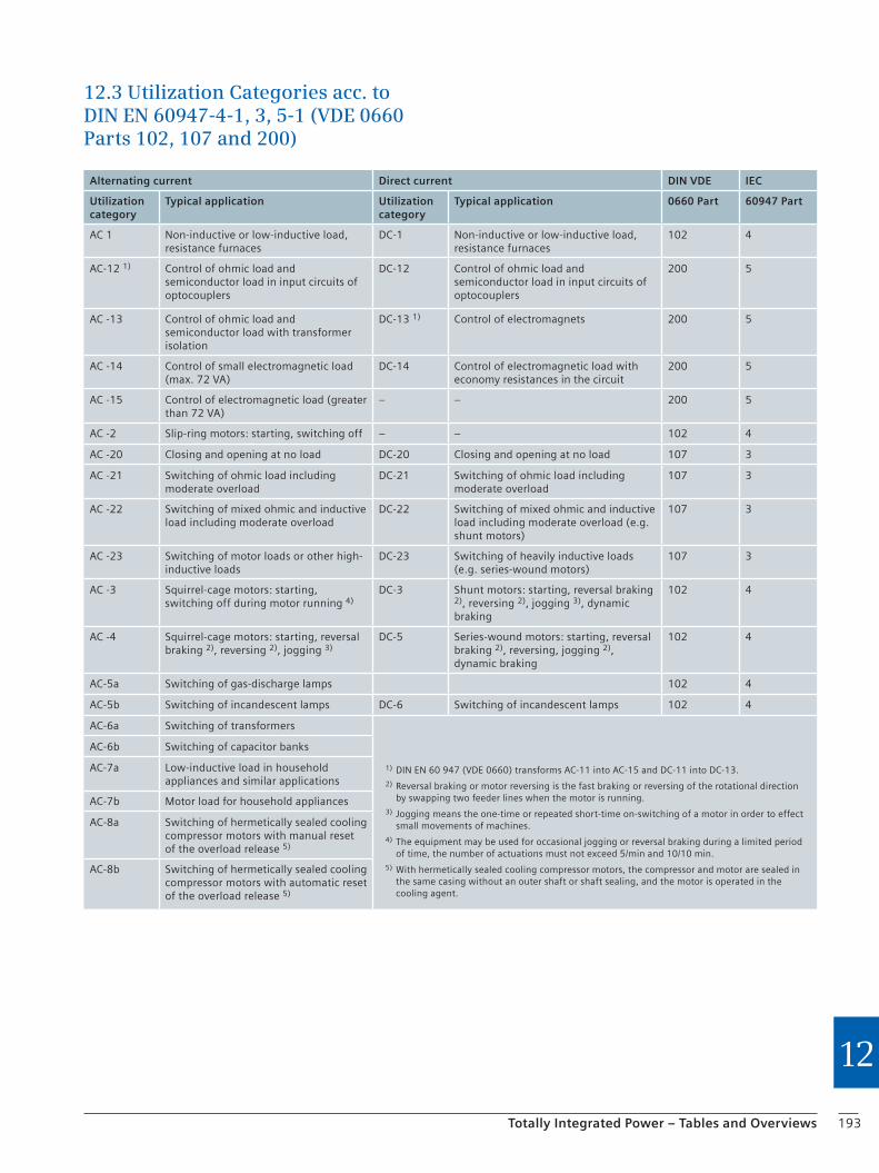
193Totally Integrated Power – Tables and Overviews
12
12.3 Utilization Categories acc. to DIN EN 60947-4-1, 3, 5-1 (VDE 0660 Parts 102, 107 and 200)
Alternating current Direct current DIN VDE IEC
Utilization category
Typical application Utilization category
Typical application 0660 Part 60947 Part
AC 1 Non-inductive or low-inductive load, resistance furnaces
DC-1 Non-inductive or low-inductive load, resistance furnaces
102 4
AC-12 1) Control of ohmic load and semiconductor load in input circuits of optocouplers
DC-12 Control of ohmic load and semiconductor load in input circuits of optocouplers
200 5
AC -13 Control of ohmic load and semiconductor load with transformer isolation
DC-13 1) Control of electromagnets 200 5
AC -14 Control of small electromagnetic load (max. 72 VA)
DC-14 Control of electromagnetic load with economy resistances in the circuit
200 5
AC -15 Control of electromagnetic load (greater than 72 VA)
– – 200 5
AC -2 Slip-ring motors: starting, switching off – – 102 4
AC -20 Closing and opening at no load DC-20 Closing and opening at no load 107 3
AC -21 Switching of ohmic load including moderate overload
DC-21 Switching of ohmic load including moderate overload
107 3
AC -22 Switching of mixed ohmic and inductive load including moderate overload
DC-22 Switching of mixed ohmic and inductive load including moderate overload (e.g. shunt motors)
107 3
AC -23 Switching of motor loads or other high-inductive loads
DC-23 Switching of heavily inductive loads (e.g. series-wound motors)
107 3
AC -3 Squirrel-cage motors: starting, switching off during motor running 4)
DC-3 Shunt motors: starting, reversal braking 2), reversing 2), jogging 3), dynamic braking
102 4
AC -4 Squirrel-cage motors: starting, reversal braking 2), reversing 2), jogging 3)
DC-5 Series-wound motors: starting, reversal braking 2), reversing, jogging 2), dynamic braking
102 4
AC-5a Switching of gas-discharge lamps 102 4
AC-5b Switching of incandescent lamps DC-6 Switching of incandescent lamps 102 4
AC-6a Switching of transformers
1) DIN EN 60 947 (VDE 0660) transforms AC-11 into AC-15 and DC-11 into DC-13.2) Reversal braking or motor reversing is the fast braking or reversing of the rotational direction
by swapping two feeder lines when the motor is running.3) Jogging means the one-time or repeated short-time on-switching of a motor in order to effect
small movements of machines.4) The equipment may be used for occasional jogging or reversal braking during a limited period
of time, the number of actuations must not exceed 5/min and 10/10 min.5) With hermetically sealed cooling compressor motors, the compressor and motor are sealed in
the same casing without an outer shaft or shaft sealing, and the motor is operated in the cooling agent.
AC-6b Switching of capacitor banks
AC-7a Low-inductive load in household appliances and similar applications
AC-7b Motor load for household appliances
AC-8a Switching of hermetically sealed cooling compressor motors with manual reset of the overload release 5)
AC-8b Switching of hermetically sealed cooling compressor motors with automatic reset of the overload release 5)
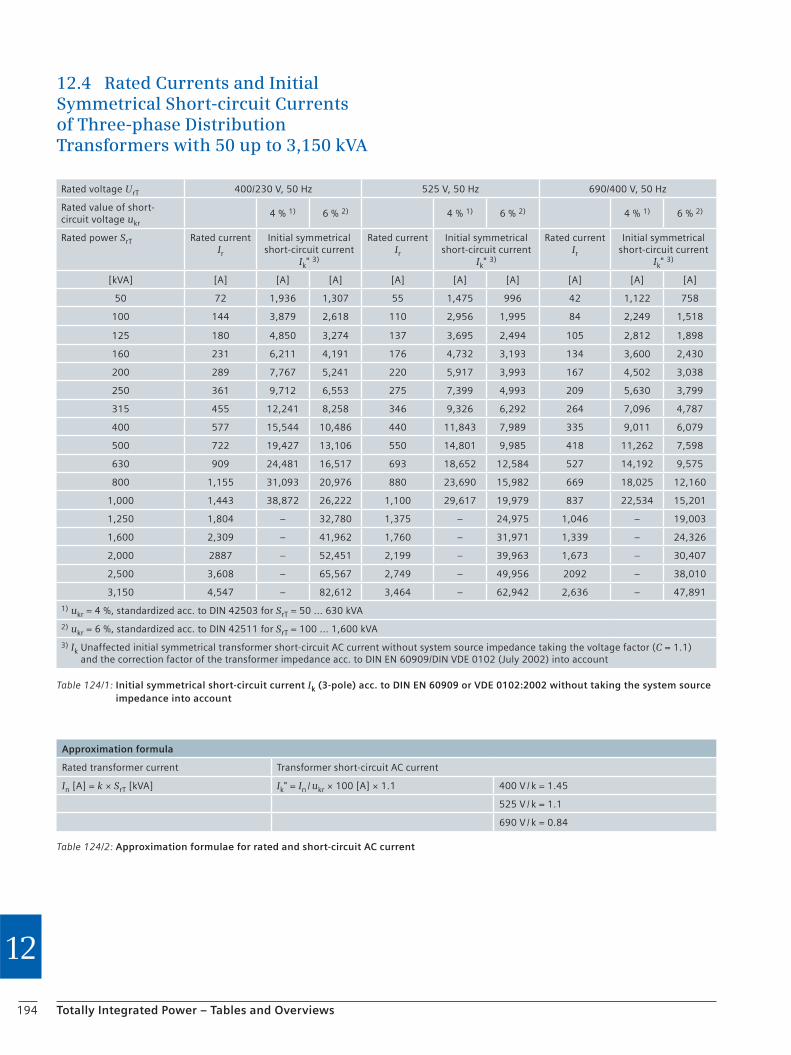
194 Totally Integrated Power – Tables and Overviews
12
12.4 Rated Currents and Initial Symmetrical Short-circuit Currents of Three-phase Distribution Transformers with 50 up to 3,150 kVA
Table 124/1: Initial symmetrical short-circuit current Ik (3-pole) acc. to DIN EN 60909 or VDE 0102:2002 without taking the system source impedance into account
Rated voltage UrT 400/230 V, 50 Hz 525 V, 50 Hz 690/400 V, 50 Hz
Rated value of short-circuit voltage ukr
4 % 1) 6 % 2) 4 % 1) 6 % 2) 4 % 1) 6 % 2)
Rated power SrT Rated current Ir
Initial symmetrical short-circuit current
Ik" 3)
Rated current Ir
Initial symmetrical short-circuit current
Ik" 3)
Rated current Ir
Initial symmetrical short-circuit current
Ik" 3)
[kVA] [A] [A] [A] [A] [A] [A] [A] [A] [A]
50 72 1,936 1,307 55 1,475 996 42 1,122 758
100 144 3,879 2,618 110 2,956 1,995 84 2,249 1,518
125 180 4,850 3,274 137 3,695 2,494 105 2,812 1,898
160 231 6,211 4,191 176 4,732 3,193 134 3,600 2,430
200 289 7,767 5,241 220 5,917 3,993 167 4,502 3,038
250 361 9,712 6,553 275 7,399 4,993 209 5,630 3,799
315 455 12,241 8,258 346 9,326 6,292 264 7,096 4,787
400 577 15,544 10,486 440 11,843 7,989 335 9,011 6,079
500 722 19,427 13,106 550 14,801 9,985 418 11,262 7,598
630 909 24,481 16,517 693 18,652 12,584 527 14,192 9,575
800 1,155 31,093 20,976 880 23,690 15,982 669 18,025 12,160
1,000 1,443 38,872 26,222 1,100 29,617 19,979 837 22,534 15,201
1,250 1,804 – 32,780 1,375 – 24,975 1,046 – 19,003
1,600 2,309 – 41,962 1,760 – 31,971 1,339 – 24,326
2,000 2887 – 52,451 2,199 – 39,963 1,673 – 30,407
2,500 3,608 – 65,567 2,749 – 49,956 2092 – 38,010
3,150 4,547 – 82,612 3,464 – 62,942 2,636 – 47,891
1) ukr = 4 %, standardized acc. to DIN 42503 for SrT = 50 ... 630 kVA
2) ukr = 6 %, standardized acc. to DIN 42511 for SrT = 100 ... 1,600 kVA
3) Ik Unaffected initial symmetrical transformer short-circuit AC current without system source impedance taking the voltage factor (C = 1.1) and the correction factor of the transformer impedance acc. to DIN EN 60909/DIN VDE 0102 (July 2002) into account
Table 124/2: Approximation formulae for rated and short-circuit AC current
Approximation formula
Rated transformer current Transformer short-circuit AC current
In [A] = k × SrT [kVA] Ik" = In / ukr × 100 [A] × 1.1 400 V / k = 1.45
525 V / k = 1.1
690 V / k = 0.84
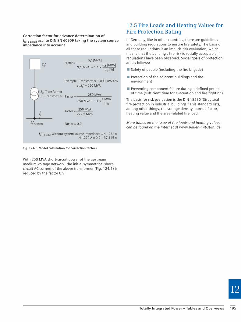
195Totally Integrated Power – Tables and Overviews
12
Correction factor for advance determination of Ik (3-pole) acc. to DIN EN 60909 taking the system source impedance into account
With 250 MVA short-circuit power of the upstream medium-voltage network, the initial symmetrical short-circuit AC current of the above transformer (Fig. 124/1) is reduced by the factor 0.9.
Sk" [MVA]Factor = ―――――――――――
Sk" [MVA] + 1.1 × ――――SrT [MVA]
ukr [%]
Example: Transformer 1,000 kVA/4 % at Sk" = 250 MVA
250 MVAFactor = ―――――――――250 MVA + 1.1 × ―――1 MVA
4 %
250 MVA277.5 MVA
Factor = ―――――
Factor = 0.9
Sk"
SrT Transformerukr Transformer
Ik" (3-pole)
Ik" (3-pole) without system source impedance = 41,272 A41,272 A × 0.9 = 37,145 A
Fig. 124/1: Model calculation for correction factors
12.5 Fire Loads and Heating Values for Fire Protection RatingIn Germany, like in other countries, there are guidelines and building regulations to ensure fire safety. The basis of all these regulations is an implicit risk evaluation, which means that the building's fire risk is socially acceptable if regulations have been observed. Social goals of protection are as follows:
Safety of people (including the fire brigade)
Protection of the adjacent buildings and the environment
Preventing component failure during a defined period of time (sufficient time for evacuation and fire-fighting).
The basis for risk evaluation is the DIN 18230 “Structural fire protection in industrial buildings.” This standard lists, among other things, the storage density, burnup factor, heating value and the area-related fire load.
More tables on the issue of fire loads and heating values can be found on the Internet at www.bauen-mit-stahl.de.

196 Totally Integrated Power – Tables and Overviews
12
12.6 Planning with Software Support
12.6.1 SIMARIS® Software Tools
The SIMARIS software family can be used to calculate electrical power distribution reliably and the necessary devices and distribution boards can be determined. The SIMARIS tool family is specially suited for electrical plan-ning ranging from the determination of basic data to tendering:
SIMARIS design for network calculations and dimensioning
SIMARIS project for calculating the space requirements of the distribution boards and the budget
SIMARIS curves for comparing characteristic time-current curves and displaying cut-off current and let-through energy curves
Tool use does not require any special knowledge of Siemens products and systems, as they are automatically determined by the software based on user specifications. Each software tool can be used individually. Project data can be exchanged for the purpose of efficiency increase.
SIMARIS design
Based on the requirements of the specific power distribu-tion system, the SIMARIS design dimensioning software safely and reliably dimensions a system solution from a broad product portfolio, in compliance with all relevant standards (VDE, IEC) and reflecting the present state of technology – ranging from medium-voltage feed-in to the power consumers. The planner needn't perform time-con-suming data research in catalogs or check standards. Besides an automatic selection of suitable components and distribution board systems, the software also performs, among other things, calculations of short-circuit current, load flow and voltage drop. And the settings regarding personal, short-circuit and overload protection will be performed automatically in line with the calculations made. Users are provided with convenient options for documenting results and for project export so that they are able to re-use project data in SIMARIS project.
More detailed information on SIMARIS design can be obtained from your local Siemens contact and on the Internet at www.siemens.com/simarisdesign.
SIMARIS project
The free SIMARIS project software, which is tailored to the needs of planners, enables a quick overview of the budget and the space requirements inside the building for power distribution systems from the medium voltage level to the distribution board for installations. After the project tree has been created, it is sufficient to select the required devices per installation – without detailed knowledge of devices or order numbers. The optimal distribution board systems are automatically determined and equipped with devices. The software factors in wiring, control, measure-ment etc. automatically. If a network diagram is imported from SIMARIS design, device selection can be omitted. Moreover, the software provides options for a subsequent optimization or change of systems.
For cost finding and further project support, e.g. for pre-paring alternative installations, the project file shall be passed on to the responsible contact partner. There are various output options for documentation purposes.
More detailed information on SIMARIS design can be obtained from your local Siemens contact and on the Internet at www.siemens.com/simarisproject
SIMARIS curves
The free SIMARIS curves software enables the comparison between characteristic tripping curves of low-voltage protective devices and fuses (IEC) made by Siemens. Possi-ble parameter settings at protective devices can be simu-lated to determine the optimal selective behavior of two series-connected devices. Let-through current and let-through energy curves are offered in addition. A printout documents the selected settings.
SIMARIS curves can be obtained free of charge at www.siemens.com/simaris/download
Fig. 126/1: Intuitive software operating interfaces facilitate electrical planning

197Totally Integrated Power – Tables and Overviews
12
12.6.2 More Tools for Planning a Power Distribution System
Complex network calculations with PSS™ SINCAL
The PSS™ SINCAL software tool is used for network planning and designing complex meshed networks in high, medium and low voltage environments (power utility and industrial networks). It enables calculations of load flows and short circuits to be prepared together with a documentation of current-time curves for selected grading paths. PSS™ SINCAL is also suitable for analyzing existing networks, makes suggestions on network expansion, rating details and the preparation of proofs that bear building authorities’ scrutiny, e.g. selectivity proofs. This tool is offered at your expense as a service for engineering consultants by Siemens.
More detailed information on PSS™ SINCAL can be obtained from your Siemens contacts in the area on page 205 or on the Internet at www.siemens.com/tip –> Benefits –> Consultant –> Contact Partner.
Siblitz calculation tool for lightning protection
Protection measures are required to reduce damage caused by the impact of lightning. Siblitz© is a software tool for the fast and comprehensive calculation of damage risks.
You can find Siblitz on the Internet at www.siemens.com/tip –> Benefits–> Consultant –> Tools.
PROFIX configuration tool for medium-voltage switchgear
The PROFIX 8DJ/8DH and PROFIX NXPLUS C configuration tools create a block diagram, a front view and appropriate construction details for our medium-voltage switchgear. With its “Export” function, the graphics generator provides the option to save plans in a neutral data format, in EMF (Enhanced Windows Metafile) and DXF (AutoCad).
You can download PROFIX quite conveniently from the Internet at www.siemens.com/profix
Pressure calculation tool for 8 DJ and 8DH10 medium-voltage switchgear
This software tool provides a simplified pressure calcula-tion for 8DJ and 8DH10 medium-voltage switchgear based on Pigler. The tool computes a good approximation for enclosed areas if the room fills evenly with pressure. For any other medium-voltage switchgear, for highly complex geometries or higher short-circuit loads, it is necessary to perform a more detailed pressure calculation with 3D finite elements which also takes dynamic pressure development into account.
Pressure calculation is provided as a customer service by Siemens If you would like further information in this matter, please get in touch with your contact, whom you will find on the Internet at www.siemens.com/tip –> Benefits –> Consultant –> Contact Partner.
Configurators for SIVACON 8PS busbar trunking systems
Busbar trunking systems in low-voltage environments ensure safe and reliable transmission and distribution of electric energy from the transformer to the main and subdistribution system and the power consumer. These busbar trunking systems by Siemens are “type-tested low-voltage switchgear and controlgear assemblies” in accordance with IEC/EN 60439-1.
The configurators for our busbar trunking systems can be found on the Internet at www.siemens.com/tip –> Benefits –> Consultant –> Tools. Right below you will also find a link to further configurators for low-voltage control and distribution products.
Configuration software for low-voltage distribution systems and ALPHA SELECT meter cabinets
Distribution boards and meter cabinets can be easily and intuitively configured using this software. Configuration errors are almost eliminated by collision tests and configu-ration rules. The preparation of tender documents is sup-ported with parts lists, the layout diagram, set-up and electrical structure given as data on screen or as printout.
You can find the software package on the Internet at www.siemens.com/tip –> Benefits–> Consultant –> Tools.
Planning tools for GAMMA building management systems
This software tool for building management technology is available online on the DIN building platform free of charge. It enables the easy preparation and completion of an “STLB-Bau”-conforming master specification for building management systems based on the GAMMA product range that bears building authorities' scrutiny.
You can find this planning tool on the Internet at www.siemens.com/tip –> Benefits–> Consultant –> Tools.
Tender texts for technical building equipment
With these tender text modules for technical building equipment in commercial, institutional and industrial buildings, Siemens provides for you free of charge, quali-fied online support for the compilation of specifications of works and services.
You can find the tender texts on the Internet at www.siemens.com/ausschreibungstexte
198 Totally Integrated Power – Tables and Overviews
12
12.7 Terms and Definitions
Verification by type test
Verification performed on patterns of a switchgear assembly or parts thereof to demonstrate that the type meets the requirements of the applicable switchgear assembly standard. Note: The verification may include one or several equivalent and alternative approaches such as tests, calculations, physical measurements or the application of construction rules.
Verification by testing
Verification performed on patterns of a switchgear assembly or parts thereof to demonstrate that the type meets the requirements of the applicable switchgear assembly standard. Note: Verifications by testing correspond to type tests.
Verification by inspection
Type verification of fixed construction rules or calculations performed on patterns of a switchgear assembly or parts thereof to demonstrate that the type meets the requirements of the applicable switchgear assembly standard.
Construction rule
Defined rules for the construction of a switchgear assembly which may be applied as an alternative to verification by testing.
Verification by routine test
Verification to which every switchgear assembly is subject during and/or after its manufacture to ensure that it meets the requirements of the applicable standard.
Rated values
Note: Depending on the applied standard, different formulaic symbols may have been defined for individual terms.
In accordance with IEC/EN 61439-1, manufacturers of low-voltage switchgear and controlgear assemblies specify rated values. These rated values are to be applied in defined operating conditions, they characterize the field of application of a switchgear assembly. Rated values shall be the basis for a coordination of equipment or the configuration of the switchgear assembly.
Rated short-time withstand current (Icw)
IEC/EN 61439-1
The effective short-circuit current value given by the switchgear assembly manufacturer, given as current and time, which can be carried under defined conditions without damage.
Rated peak withstand current (Ipk)
IEC/EN 61439-1
Being the peak value of the surge current, the rated peak withstand current characterizes the dynamic strength of a circuit in a switchgear assembly. Data on the rated peak withstand current is usually given for the power distribution bars and/or main busbars of a switchgear assembly.
Rated conditional short-circuit current (Icc)
IEC/EN 61439-1
The rated conditional short-circuit current corresponds to the prospective short-circuit current which a circuit in a switchgear assembly can carry (for a certain time), being protected by a short-circuit protective device, without being damaged. For this reason, the rated conditional short-circuit current is specified for outgoing and/or incoming feeders, e.g. using circuit-breakers.
Rated current of the switchgear assembly (InA)
IEC/EN 61439-1
The rated current of the switchgear assembly is the smaller of:
the rated currents total of the incoming feeders operated in parallel within the switchgear assembly
the total current which the main busbar can distribute in the respective configuration of the switchgear assembly.
It must be possible that the current is carried without that heating the individual parts will exceed limit values.
Rated circuit current (InC)
IEC/EN 61439-1
The circuit must be able to carry this current when operated alone without that overtemperatures in individual components will exceed limit values.
199Totally Integrated Power – Tables and Overviews
12
Rated impulse withstand voltage (Uimp)
IEC/EN 60947-1
Measure for the endurance of clearances in air inside a switching device to withstand transient overvoltages. By using suitable switching devices, it can be ensured that disconnected parts cannot transmit overvoltages from the network they are in.
Rated current (In) (of a circuit-breaker)
IEC/EN 60947-2
For circuit-breakers, this current is identical with the rated continuous current and the conventional thermal current.
➜ Rated continuous current
Rated control voltage (Uc)
IEC/EN 60947-1
Voltage which is applied at the NO contact in a control circuit. It can deviate from the rated control supply voltage owing to transformers or resistors being connected in the switched circuit.
Rated ultimate short-circuit breaking capacity (Icu)
IEC/EN 60947-2
Maximum short-circuit current which a circuit-breaker can break (test O – CO). After short-circuit interruption, the circuit-breaker is capable of tripping in the event of over-load, increased tolerances must, however, be allowed for.
Rated service short-circuit breaking capacity (Ics)
IEC/EN 60947-2
The short-circuit current depending on the rated operating voltage which a circuit-breaker can repeatedly break (test O – CO – CO). After short-circuit interruption, the circuit-breaker continues to be capable of carrying the rated current at an increased amount of self-heating, and continues to be capable of tripping in case of overload.
➜ Rated continuous current; Rated operating voltage
Rated operating capacity
IEC/EN 60947-1
Power which a switching device can switch at a dedicated rated operating voltage according to its utilization category, e.g. power contactor utilization category AC-3: 37 kW at 400 V.
Rated operating voltage (Ue)
IEC/EN 60947-1
Voltage to which the characteristic data of a switching device refers. The maximum rated operating voltage must under no circumstances be higher than the rated insulation voltage.
➜ Rated insulation voltage
Rated operating current (Ie)
IEC/EN 60947-1
Current that a switching device can carry allowing for rated operating voltage, operating hours, utilization category and ambient air temperature.
➜ Rated operating voltage
Rated continuous current (Iu)
IEC/EN 60947-1
Current that a switching device can carry in a continuous operating mode (over weeks, months or years).
Rated making capacity
IEC/EN 60947-1
Current that a switching device can make corresponding to its utilization category, when the rated operating voltage is applied.
➜ Rated operating voltage
Rated frequency
IEC/EN 60947-1
Frequency for which a switching device is rated and to which its other characteristic data refer.
➜ Rated operating voltage; Rated continuous current
Rated insulation voltage (Ui)
IEC/EN 60947-1
Voltage to which the dielectric tests and creepage distances refer. The maximum rated operating voltage must under no circumstances be higher than the rated insulation voltage.
➜ Rated operating voltage

200 Totally Integrated Power – Tables and Overviews
12
Rated short-circuit breaking capacity (Icn)
IEC/EN 60947-1
Highest current that a switching device can break at the rated operating voltage and frequency without being damaged, given as the r.m.s value.
➜ Rated operating voltage
Rated short-circuit making capacity (Icm)
IEC/EN 60947-1
Highest current that a switching device can break at a certain rated operating voltage and frequency without being damaged. Unlike other characteristic data, it is given as the peak value.
➜ Rated operating voltage
Rated short-circuit current, conditional
IEC/EN 60947-1
➜ Rated conditional short-circuit current (Iq)
The explanations for the following terms are used with reference to VDE 0660, Part 500 and IEC 61439-1.
Rated diversity factor (RDF)
Rated current value given as a percentage by the switch-gear assembly manufacturer with which the outgoing feeders of a switchgear assembly can continuously and simultaneously be loaded taking the mutual thermal influences into account. The rated diversity factor may be specified:
for groups of circuits
for the entire switchgear assembly.
Number of main circuits Rated diversity factor
2 and 3 0.9
4 and 5 0.8
6 to including 9 0.7
10 and more 0.6
201Totally Integrated Power – Tables and Overviews
12
12.8 AbbreviationsA
AGI Arbeitsgemeinschaft Industriebau [Working Group on Industrial Building]
AS-i Actuator-sensor interface
B
BA Building automation
BACS Building Automation and Control Systems. EN 15232 defines four so-called performance classes for BACS
BDEW Bundesverband der Energie und Wasserwirtschaft e.V. [German Federal Association of Energy and Water Management]
BIMSchV German Federal Ordinance on the Protection against Immissions, includes ca. 40 ordinances on the implementation of the Federal Act on the Protection against Immissions (BImSchG)
C
CT Computer tomograph
D
DIN Deutsches Institut für Normung e. V.; German industrial standard
E
EEG German Act on Renewable Energies
EIB European installation bus
ELA Electro-acoustic system
EMC Electromagnetic compatibility
EMS Energy management system
EN European standard
EnEV Ordinance on energy saving
ERP Enterprise resource planning
F
FMS Facility management system (see EMS)
H
HOAI Honorarordnung für Architekten und Ingenieure (German regulation of architects’ and engineers’ fees)
HVAC Heating, ventilation, air conditioning
I
IEC International Electrotechnical Commission;
IP International Protection (acc. to DIN); also: ingress protection
K
KNX Konnex; building management system in compliance with EN 50090
L
LAN Local area network
LVMD Low-voltage main distribution
M
MRT Magnetic resonance tomograph
MVS Medium-voltage supply
N
NPS Normal power supply
O
OPC OLE for process control (OLE = object linking and embedding)
P
PTC Positive temperature coefficient; PTC resistor
R
RDF Rated diversity factor
RPS Redundant/standby power supply
S
SCADA Supervisory control and data acquisition, concept for monitoring and control of technical processes
SF Simultaneity factor
SHV Smoke and heat vents
SPS Safety power supply
T
TA Technische Anleitung (technical instruction)
TAB Technische Anschlussbedingungen; technical supply conditions (of the supply network operator)
TBM Technical building management
THD Total harmonic distortion
THDI Total harmonic distortion index; input current distortion factor
TÜH Staatliche Technische Überwachung Hessen (Governmental Technical Control Board of Hesse/Germany)
TÜV Technischer Überwachungsverein (German Technical Control Board)
U
UGR Unified glare rating
UPS Uninterruptible power supply
V
VDE Verband der Elektrotechnik, Elektronik und Informationstechnik e.V.
VDEW Verband der Elektrizitätswirtschaft e. V.
VDN Association of Network Operators in the VDEW/VDN
VNB Supply network operator
202 Totally Integrated Power – Tables and Overviews
12
1 Planning with Totally Integrated Power
1.1 Introduction 1/2
1.2 Draft Planning
(System and Integration Planning) 1/3
2 Power System
2.1 Overview 2/2
2.2 Dimensioning of Power Distribution Systems 2/10
2.3 System Protection and Safety Coordination 2/14
2.4 Protection Equipment
for Low-Voltage Power Systems 2/20
2.5 Selectivity in Low-Voltage Systems 2/41
2.6 Protection of Capacitors 2/52
2.7 Protection of Distribution Transformers 2/53
2.8 Protection of Technical Building Installations –
Lightning Current and Overvoltage Protection 2/62
3 Medium Voltage
3.1 Introduction 3/2
3.2 Basics of Switchgear 3/3
3.3 Requirements on Medium-Voltage Switchgear 3/7
3.4 Siemens Medium-Voltage Switchgear 3/9
3.5 From Medium-Voltage Switchgear
to Turnkey Solutions 3/25
3.6 Protection of Power Distribution Systems
and Switchgear 3/28
4 Transformers
4.1 Distribution Transformers 4/2
4.2 Control and Isolating Transformers 4/6
5 Power Generation
5.1 Grid-Connected Photovoltaic (PV) Systems 5/2
5.2 Basis for the Use of UPS 5/5
6 Low Voltage
6.1 Low-Voltage Switchgear 6/2
6.2 Protective and Switching Devices in the Low-Voltage Power Distribution 6/9
6.3 Requirements of the Switchgear in the Three Circuit Types 6/11
6.4 Container Solutions 6/14
7 Busbar Trunking Systems, Cables and Wires
7.1 Busbar Trunking Systems 7/2
7.2 Cables and Wires 7/10
8 Subdistribution Systems
8.1 General 8/2
8.2 Configuration 8/2
8.3 Selectivity and Back-up Protection 8/3
8.4 Small Distribution Boards and Wall- or Floor-Mounted Distribution Boards 8/6
8.5 Circuit Protection Devices 8/9
9 Power Consumers
9.1 Starting, Switching and Protecting Motors 9/2
9.2 Lighting 9/8
9.3 Elevator Systems 9/19
10 Ease of Operation, Safety and Control Engineering
10.1 Power Management with SIMATIC powercontrol 10/2
10.2 Building Management System 10/7
10.3 Energy Automation for the Industry 10/14
10.4 Safety Lighting Systems 10/20
10.5 Robust Remote Terminal Unit for Extreme Environmental Conditions (SIPLUS RIC) 10/27
11 Appendix
12.9 Contents: Application Manual – Part 2: Draft Planning 2007

203Totally Integrated Power – Tables and Overviews
12
Contact Partners for Special Subjects
Consultant Support
Austria Erich Thauer Tel.: +43 5 17 07 2 29 86 E-mail: [email protected]
Leopold Holzhacker Tel.: +43 5 17 07 2 33 30 E-mail: [email protected]
Greece Ilias Antoniou Tel.: +30 2 10 68 64-3 79 E-mail: [email protected]
Italy Paolo Parma Tel.: +39 02 24 36 29 52 E-mail: [email protected]
Netherlands Merijn Dijkema Tel.: +31 70 3 33 21 52 E-mail: [email protected]
Portugal Jose Alves Calado Tel.: +3 51 21 4 17 84 69 E-mail: [email protected]
Anabela Correao Tel.: +3 51 21 4 17 84 69 E-mail: [email protected]
Russia Alexander Bourlaka Tel.: +7 4 95 7 37 23 39 E-mail: [email protected]
Schwitzerland Roger Weigold Tel.: +41 58 5 58 65 18 E-mail: [email protected]
Spain Ramon Rodriguez Belda Tel.: +34 91 5 14-70 55 E-mail: [email protected]
Turkey Ali Kaan Eryasar Tel.: +90 2 16 4 59 32 28 E-mail: [email protected]
United Kingdom Howard John Tel.: +44 1 61 4 46 64 00 E-mail: [email protected]
China Mr. He You Lin Tel.: +86 21 38 89-30 82 E-mail: [email protected]
Mr. Ge Da Lin Tel.: +86 21 38 89-26 65 E-mail: [email protected]
USA Bill Reid Tel.: +1 913 8 88 26 46 E-mail: [email protected]
Your Siemens Contact Partners
Lighting technology
Siteco Beleuchtungstechnik GmbH Technical Support Georg-Simon-Ohm-Straße 50 83301 Traunreut / Upper Bavaria, Germany Tel.: +49 86 69 / 3 38 44 Fax: +49 86 69 / 3 35 40 E-mail: [email protected] www.siteco.de or www.siteco.com
Reactive power compensation
MODL GmbH Sales Management Langenaltheimer Straße 5–9 91788 Pappenheim, Germany
Gerd Sonnek Tel.: +49 91 43 / 6 03-56 Fax: +49 91 43 / 6 03-12 E-mail: [email protected]
Standby power supply systems
Evers & Co. Standard Aggregatebau KG Grünauer Straße 24 12557 Berlin, Germany Tel.: +49 30 / 65 47 27 23 Fax: +49 30 / 65 47 27 26 www.sab-hamburg.de
Lutz Schulz E-mail: [email protected]
Uninterruptible power supply systems
MASTERGUARD GmbH PO Box 2620 91014 Erlangen, Germany Fax: 0 91 31 / 6 30 03 00 www.masterguard.info
Infoline (weekdays 9.00 am – 5.00 pm) Tel.: +49 1 80 / 5 32 37 51 E-mail: [email protected]

204 Totally Integrated Power – Tables and Overviews
12
ImprintTotally Integrated Power Application Manual – Part 1: Basic Data and Preliminary Planning 2nd edition 2009
Published by
Siemens Aktiengesellschaft
Sector IndustryDivision Automation and DrivesDivision Building Technologies
Sector EnergyDivision Power Transmission and Distribution
Editor and Author
Ralf Willeke, Siemens AG, I IA CD TIP
Layout
Publicis KommunikationsAgentur GmbH, GWA Nägelsbachstr. 33 91052 Erlangen, Germany
Image rights
Page 25 © Roland Halbe/Messe Stuttgart; Page 31, 59 Wolfgang Geyer/Forum Wetzlar; Page 5, 139, 147, 153 Dominik Obertreis/Flughafen Stuttgart. Any other non-identified photographs and graphics © Siemens AG.
Hofmann Infocom AG Emmericher Straße 10 90411 Nuremberg, Germany
Bindery
Thalhofer, 71101 Schönaich, Germany
ethabind jacket protected by patent
© 2009 Siemens Aktiengesellschaft Berlin and Munich
All rights reserved. Token fee 24.00 euros All data and circuit examples without engagement.
Subject to changes.
Order No. E20001-A110-M104-X-7600
Dispo 27612
The omission of any specific reference with regard to trademarks, brand names,
technical solutions, etc., does not imply that they are not protected by patent.
We would like to thank the companies MASTERGUARD (UPS), Modl (reactive power compensation), Siteco (lighting technology) and Evers & Co. Standard Aggre-gatebau KG (standby power supply systems) for their technical support in the preparation of this manual.

Conversion Factors and Tables
Energy, work, heat content
SI unitNon-metric unit
SI unit Non-metric unit
1 kWh 1.341 hp h = 2.655 kgf m1 J = 3.6 × 10⁵ J
3.725 × 10⁻⁷ hp h = 0.738 ft lbf =
1 kgf m 9.478 × 10⁻⁴ Btu (= 2.388 × 10⁻⁴ kcal
3.653 × 10⁻⁶ hp h = 7.233 ft lbf
1 hp h 0.746 kWh = 2.684 × 10⁶ J
1 ft lbf = 2.737 × 10⁵ kgf m
1 Btu 0.138 kgf m 1.055 kJ = 1,055.06 J (= 0.252 kcal)
SI unit Non-metric unit
Pressure
SI unitNon-metric unit
1 bar 29.53 in Hg == 105 pa 14.504 psi == 102 kpa 2088.54 lbf/ft2 = 14.504 lbf/in2 = 0.932 tonf/ft2
6.457 × 10⁻³ tonf/in2
(= 1.02 kgf/cm2)
1 in HG 0.034 bar
1 psi 0.069 bar
1 lbf/ft2 4.788 × 10⁻⁴ bar =1 lbf/in2 4.882 × 10⁻⁴ kgf/cm2
1 tonf/ft2 0.069 bar = 0.070 kgf/cm2
1 tonf/in2 1.072 bar = 1.093 kgf/cm2
154.443 bar = 157.488 kgf/cm2
Volume flow rate
SI unit Non-metric unit
SI unitNon-metric unit
1 l/s 0.264 Gallone/s
1 l/h 0.0044 Gallone/min
1 m3/h 4.405 Gallone/min = 0.589 ft3/min = 0.0098 ft3/s
1 Gallone/s 3.785 l/s
1 Gallone/min 0.227 m3/h = 227 l/h
1 ft3/s 101.941 m3/h
1 ft3/min 1.699 m3/h
Moment of inertia
SI unit Non-metric unit
SI unitNon-metric unit
Numerical value equation J = –––– = Wr2
1 kg m2 23.73 lb ft2
1 lbf ft2 0.04214 kg m2
GD2
4
SI unit Non-metric unit
SI unitNon-metric unit
Torque, moment of force
1 Nm 8.851 lbf in = 0.738 lbf ft (= 0.102 kgf m)
1 lbf in 0.113 Nm = 0.012 kgf m
1 lbf ft 1.356 Nm = 0.138 kgf m
Force
SI unit Non-metric unit
SI unitNon-metric unit
1 N 0.225 lbf = 0.102 kgf
1 kN 0.100 tonf
1 lbf 4.448 N
1 kgf 9.807 N
1 tonf 9.964 kN
Volume
SI unit Non-metric unit
SI unitNon-metric unit
1 cm3 0.061 in3 = 0.034 fl. oz
1 dm3 61.024 in3 =
= 1 l 0.035 ft3 = 1.057 Quart =
2.114 Pint = 0.264 Gallone
1 m3 6.29 Barrel
1 in3 16.387 cm3
1 ft3 28.317 dm3 = 0.028 m3
1 yd3 0.765 m3
1 fl. oz. 29.574 cm3
1 Quart 0.946 dm3 = 0.946 l
1 Pint 0.473 dm3 = 0.473 l
1 Gallone 3.785 dm3 = 3.785 l
1 Barrel 159 dm3 = 0.159 m3 = 159 l
SI unit Non-metric unit
Mass, weight
SI unitNon-metric unit
1 g 0.035 oz
1 kg 2.205 lb = 35.27 oz
1 t 1.102 sh ton = 2205 lb
1 oz 28.35 g
1 lb 0.454 kg = 453.6 g
1 sh ton 0.907 t = 907.2 kg
Velocity
SI unit Non-metric unit
SI unitNon-metric unit
1 m/s 3.281 ft/s = 2.237 mile/h
1 km/h 0.911 ft/s = 0.621 mile/h
1 ft/s 0.305 m/s = 1.097 km/h
1 mile/h 0.447 m/s = 1.609 km/h

Conversion Factors and Tables
Examples of decimal multiplesand fractions of metric units
1 km = 1,000 m;1 m = 100 cm = 1,000 mm
1 km2 = 1,000,000 m2;1 m2 = 10,000 cm2;1 cm2 = 100 mm2
1 m3 = 1,000,000 cm3;1 cm3 = 1,000 mm3
1 t = 1,000 kg; 1 kg = 1,000 g
1 kW = 1,000 W
Btu = British thermal unit
Btu/h = British thermal unit/hour
lbf = pound force
tonf = ton force
Temperature
Note:Quantity Symbol Unit
Temperaturein degrees Fahrenheit
Temperaturein degrees Celsius
Thermodynamictemperature in Kelvin
SI unitNon-metric unit
SI unit Non-metric unit
°C °F – (∂C + 32) = ∂F
K °F – (∂T – 459.67) = ∂F
95
59
°F °C – (∂F – 32) = ∂C
°F K – (∂F + 459.67) = T
95
59
∂F °F
∂C °C
T K
Electrical power
SI unitNon-metric unit
SI unit Non-metric unit
1 kW 1.341 hp = 101.972 kgf m/s (= 1.36 PS)
1 W 0.738 ft lbf/s = 0.86 kcal/h = 3.412 Btu (= 0.102 kgf m/s)
1 hp 0.746 kW = 745.70 W = 76.040 kgf m/s1 ft lbf/s (= 1.014 PS)
1 kcal/h 1.356 W (= 0.138 kgf in/s)
1 Btu/h 1.163 W
0.293 W
Specific steam consumption
SI unit Non-metric unit
SI unitNon-metric unit
1 kg/kWh 1.644 lb/hp h
1 lb/hp h 0.608 kg/kWh
Square measure
SI unit Non-metric unit
SI unitNon-metric unit
1 mm2 0.00155 in2
1 cm2 0.155 in2
1 m2 10.76 ft2 = 1550 in2
= 1.196 yd2
1 km2 0.366 mile2
1 in2 6.452 cm2 = 645.16 mm2
1 ft2 0.093 m2 = 929 cm2
1 yd2 0.836 m2
1 acre 4046.9 m2
1 mile2 2.59 km2
Linear measure
SI unit Non-metric unit
SI unitNon-metric unit
1 mm 39.37 mil
1 cm 0.394 in
1 m 3.281 ft = 39.370 in
= 1.094 yd
1 km 0.621 mile = 1.094 yd
1 mil 0.0254 mm
1 in 2.54 cm = 25.4 mm
1 ft 30.48 cm = 0.305 m
1 yd 0.914 m
1 mile 1.609 km = 1,609 m
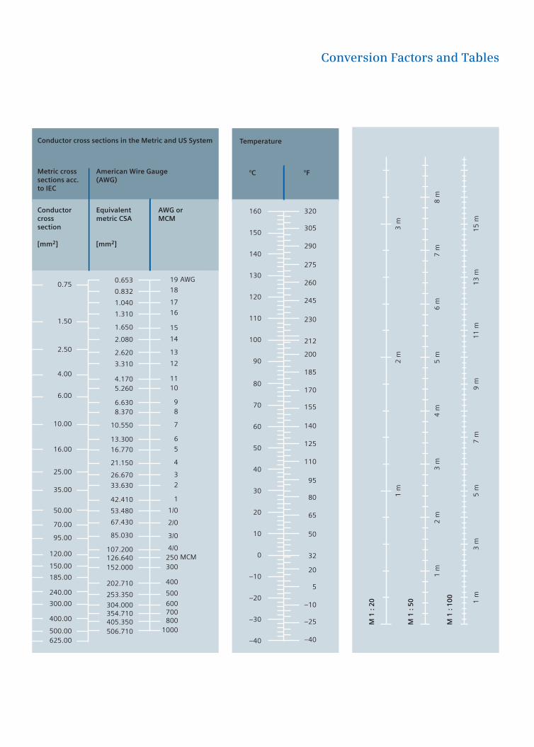
Conversion Factors and Tables
TemperatureConductor cross sections in the Metric and US System
Metric cross American Wire Gaugesections acc. (AWG)to IEC
Conductor Equivalent AWG orcross metric CSA MCMsection
0.75
1.50
2.50
4.00
6.00
10.00
16.00
25.00
35.00
50.00
70.00
95.00
120.00
150.00
185.00
240.00
300.00
400.00
500.00625.00
0.653
0.832
1.040
1.310
1.650
2.080
2.620
3.310
4.1705.260
6.6308.370
10.550
13.300
16.770
21.150
26.670
33.630
42.410
53.480
67.430
85.030
107.200126.640152.000
202.710
253.350
304.000354.710405.350506.710
1 m
3 m
5 m
7 m
9 m
11
m1
3 m
15
m
M 1
: 2
0
1 m
2 m
3 m
M 1
: 5
0
1 m
2 m
3 m
4 m
5 m
6 m
7 m
8 m
M 1
: 1
00
19
18
17
16
15
14
13
12
1110
9 8
7
6
5
4
3
2
1
1/0
2/0
3/0
4/0 250 300
400
500
600 700 800
1000
AWG
MCM
160
150
140
130
120
110
100
90
80
70
60
50
40
30
20
10
0
–10
–20
–30
–40
320
305
290
275
260
245
230
212
200
185
170
155
140
125
110
95
80
65
50
32
20
5
–10
–25
–40
°C °F
[mm2] [mm2]

The information provided in this manual contains merely general descriptions or characteristics of performance which in case of actual use do not always apply as de-scribed or which may change as a result of further development of the products. An obligation to provide the respective characteristics shall only exist if expressly agreed in the terms of contract.
All product designations may be trademarks or product names of Siemens AG or supplier companies whose use by third parties for their own purposes could violate the rights of the owners.
w w w. s i e m e n s . c o m / t i p
Siemens AGIndustry SectorIndustry Automation and Drive TechnologiesGleiwitzer Straße 55590475 NUREMBERGGERMANY
Siemens AGEnergy SectorPower DistributionFreyeslebenstr. 191058 ERLANGENGERMANY
Building Technologies GroupGubelstraße 226301 ZUGSWITZERLAND