appendix vibration analysis report - 'virginia avenue … avenue tunnel reconstruction project...
TRANSCRIPT
Appendix F Vibration Analysis Report

VIRGINIA AVENUE TUNNELRECONSTRUCTION PROJECT
Revised March 2014
VIBRATION ANALYSIS REPORTVIBRATION ANALYSIS REPORT

VIRGINIA AVENUE TUNNEL RECONSTRUCTION PROJECT
WASHINGTON, DC
VIBRATION ANALYSIS REPORT
REVISED: March 2014
Prepared by CLARK/PARSONS, JOINT VENTURE
100 M Street, SE, Suite 1200 Washington, DC 20003
Phone: 202-775-3300. Fax: 202-775-3420

i
TABLE OF CONTENTS LIST OF TABLES ........................................................................................................................ ii
LIST OF FIGURES ...................................................................................................................... ii
ACRONYMS AND ABBREVIATIONS ................................................................................ iv
STANDARDS ............................................................................................................................. iv
EXECUTIVE SUMMARY .................................................................................................... ES-1
CHAPTER 1 – INTRODUCTION ......................................................................................... 1-1 1.1 Purpose of Vibration Study ......................................................................................................... 1-1 1.2 Project Description ........................................................................................................................ 1-1
CHAPTER 2 – VIBRATION BACKGROUND ................................................................... 2-1
CHAPTER 3 – IMPACT CRITERIA ..................................................................................... 3-1 3.1 Operation Vibration Impact Criteria .......................................................................................... 3-1 3.2 Construction Impact Criteria ....................................................................................................... 3-2
CHAPTER 4 – EXISTING SETTING AND MEASUREMENT METHODOLOGY .... 4-1 4.1 Existing Land Use ......................................................................................................................... 4-1 4.2 Vibration Measurement Methodology ....................................................................................... 4-1 4.3 Soil Propagation Characteristics ............................................................................................... 4-12
CHAPTER 5 – IMPACT ASSESSMENT ............................................................................. 5-1 5.1 Construction Vibration ................................................................................................................. 5-1 5.2 Train Operation Vibration ........................................................................................................... 5-2
CHAPTER 6 – MITIGATION ................................................................................................ 6-1 6.1 Construction Vibration Mitigation ............................................................................................. 6-1 6.2 Train Operation Vibration Mitigation ........................................................................................ 6-3
APPENDIX A – VIBRATION MEASUREMENT SITES ................................................. A-1
APPENDIX B – SOIL VIBRATION TRANSFERABILITY AND REDUCTION DATA ........................................................................ B-1
APPENDIX C – CONSTRUCTION ACTIVITIY .............................................................. C-1
Virginia Avenue Tunnel Reconstruction Project
ii
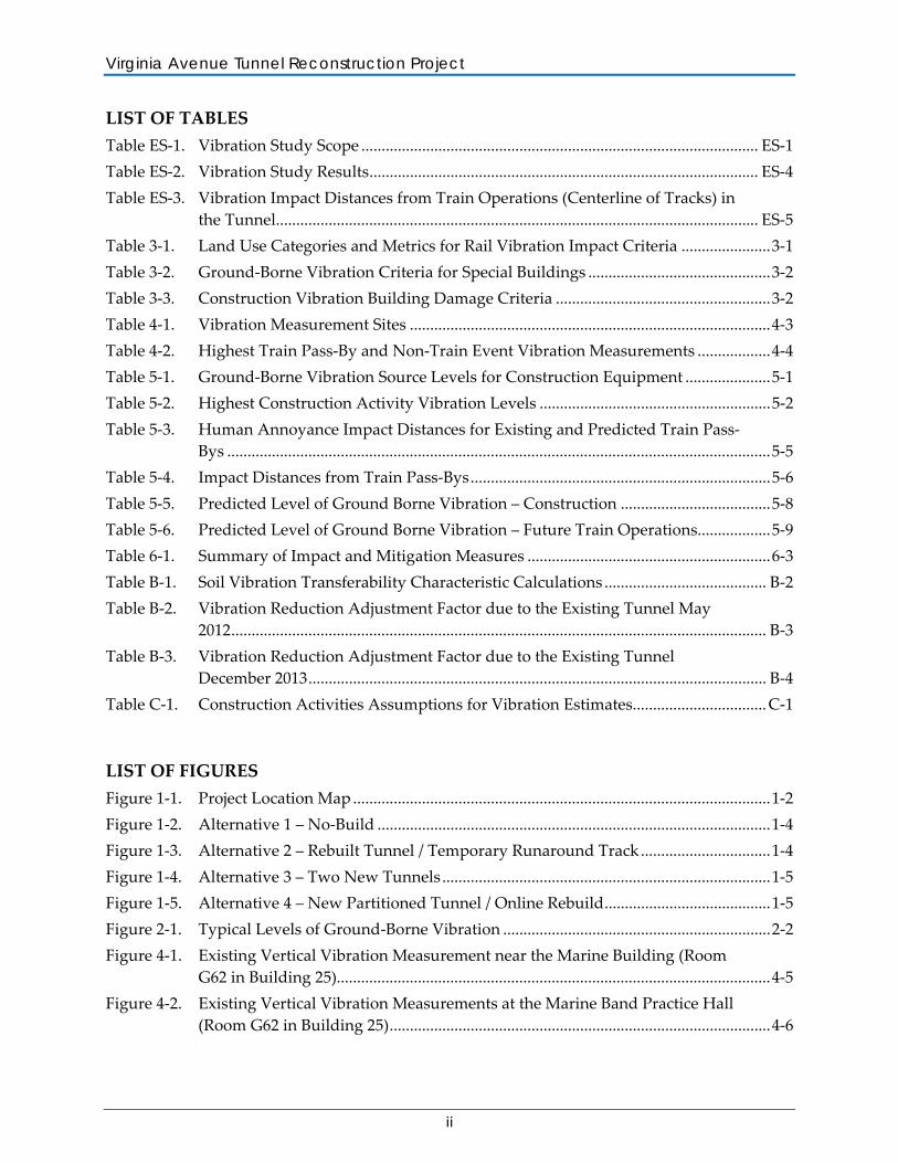
LIST OF TABLES Table ES-1. Vibration Study Scope .................................................................................................. ES-1 Table ES-2. Vibration Study Results ................................................................................................ ES-4 Table ES-3. Vibration Impact Distances from Train Operations (Centerline of Tracks) in
the Tunnel....................................................................................................................... ES-5 Table 3-1. Land Use Categories and Metrics for Rail Vibration Impact Criteria ...................... 3-1 Table 3-2. Ground-Borne Vibration Criteria for Special Buildings ............................................. 3-2 Table 3-3. Construction Vibration Building Damage Criteria ..................................................... 3-2 Table 4-1. Vibration Measurement Sites ......................................................................................... 4-3 Table 4-2. Highest Train Pass-By and Non-Train Event Vibration Measurements .................. 4-4 Table 5-1. Ground-Borne Vibration Source Levels for Construction Equipment ..................... 5-1 Table 5-2. Highest Construction Activity Vibration Levels ......................................................... 5-2 Table 5-3. Human Annoyance Impact Distances for Existing and Predicted Train Pass-
Bys ...................................................................................................................................... 5-5 Table 5-4. Impact Distances from Train Pass-Bys .......................................................................... 5-6 Table 5-5. Predicted Level of Ground Borne Vibration – Construction ..................................... 5-8 Table 5-6. Predicted Level of Ground Borne Vibration – Future Train Operations.................. 5-9 Table 6-1. Summary of Impact and Mitigation Measures ............................................................ 6-3 Table B-1. Soil Vibration Transferability Characteristic Calculations ........................................ B-2 Table B-2. Vibration Reduction Adjustment Factor due to the Existing Tunnel May
2012 .................................................................................................................................... B-3 Table B-3. Vibration Reduction Adjustment Factor due to the Existing Tunnel
December 2013 ................................................................................................................. B-4 Table C-1. Construction Activities Assumptions for Vibration Estimates................................. C-1
LIST OF FIGURES Figure 1-1. Project Location Map ....................................................................................................... 1-2 Figure 1-2. Alternative 1 – No-Build ................................................................................................. 1-4 Figure 1-3. Alternative 2 – Rebuilt Tunnel / Temporary Runaround Track ................................ 1-4 Figure 1-4. Alternative 3 – Two New Tunnels ................................................................................. 1-5 Figure 1-5. Alternative 4 – New Partitioned Tunnel / Online Rebuild ......................................... 1-5 Figure 2-1. Typical Levels of Ground-Borne Vibration .................................................................. 2-2 Figure 4-1. Existing Vertical Vibration Measurement near the Marine Building (Room
G62 in Building 25)........................................................................................................... 4-5 Figure 4-2. Existing Vertical Vibration Measurements at the Marine Band Practice Hall
(Room G62 in Building 25) .............................................................................................. 4-6
Virginia Avenue Tunnel Reconstruction Project
iii
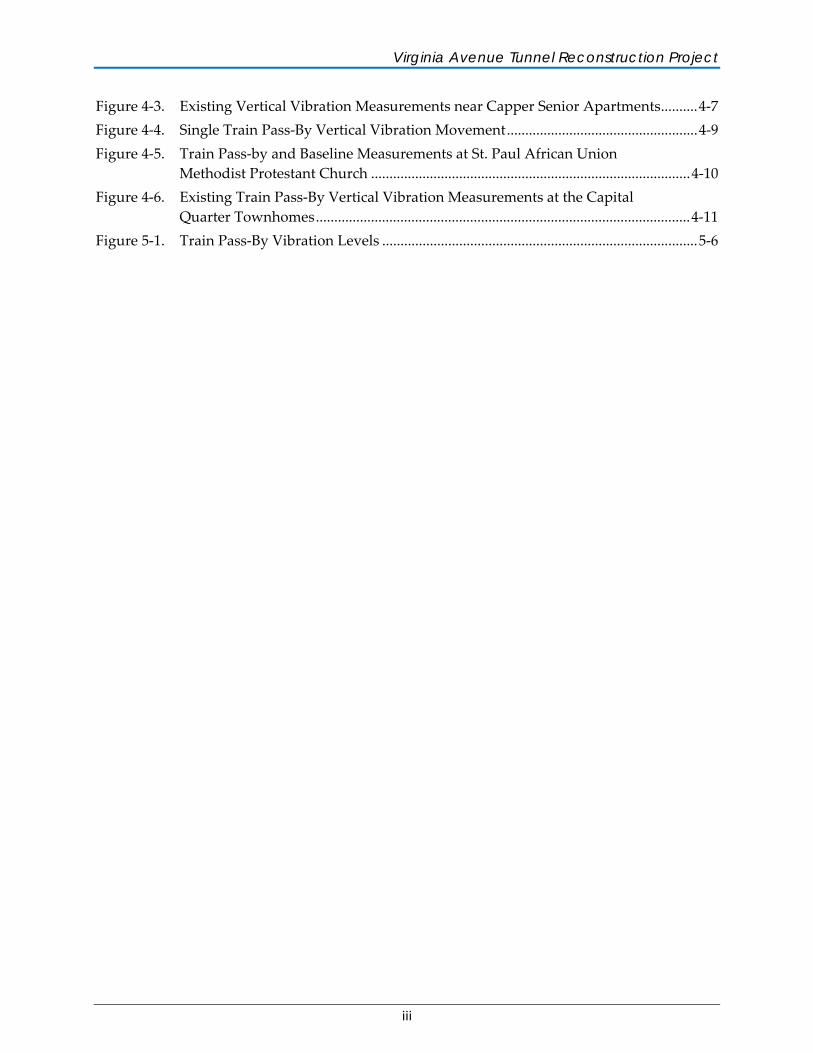
Figure 4-3. Existing Vertical Vibration Measurements near Capper Senior Apartments .......... 4-7 Figure 4-4. Single Train Pass-By Vertical Vibration Movement .................................................... 4-9 Figure 4-5. Train Pass-by and Baseline Measurements at St. Paul African Union
Methodist Protestant Church ....................................................................................... 4-10 Figure 4-6. Existing Train Pass-By Vertical Vibration Measurements at the Capital
Quarter Townhomes ...................................................................................................... 4-11 Figure 5-1. Train Pass-By Vibration Levels ...................................................................................... 5-6
iv
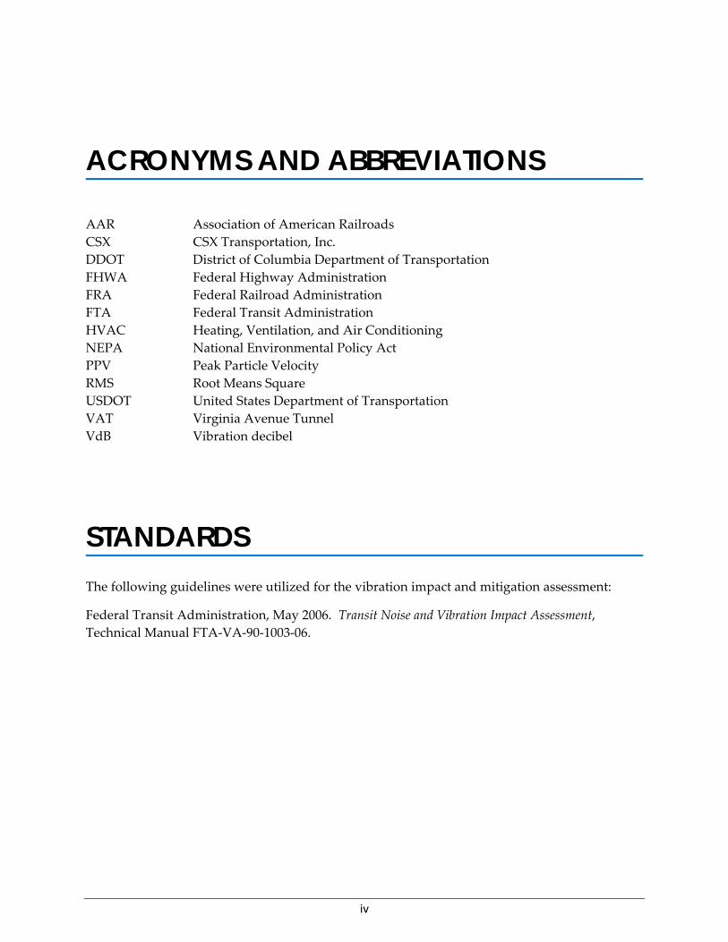
ACRONYMS AND ABBREVIATIONS AAR Association of American Railroads CSX CSX Transportation, Inc. DDOT District of Columbia Department of Transportation FHWA Federal Highway Administration FRA Federal Railroad Administration FTA Federal Transit Administration HVAC Heating, Ventilation, and Air Conditioning NEPA National Environmental Policy Act PPV Peak Particle Velocity RMS Root Means Square USDOT United States Department of Transportation VAT Virginia Avenue Tunnel VdB Vibration decibel
STANDARDS The following guidelines were utilized for the vibration impact and mitigation assessment:
Federal Transit Administration, May 2006. Transit Noise and Vibration Impact Assessment, Technical Manual FTA-VA-90-1003-06.
ES-1
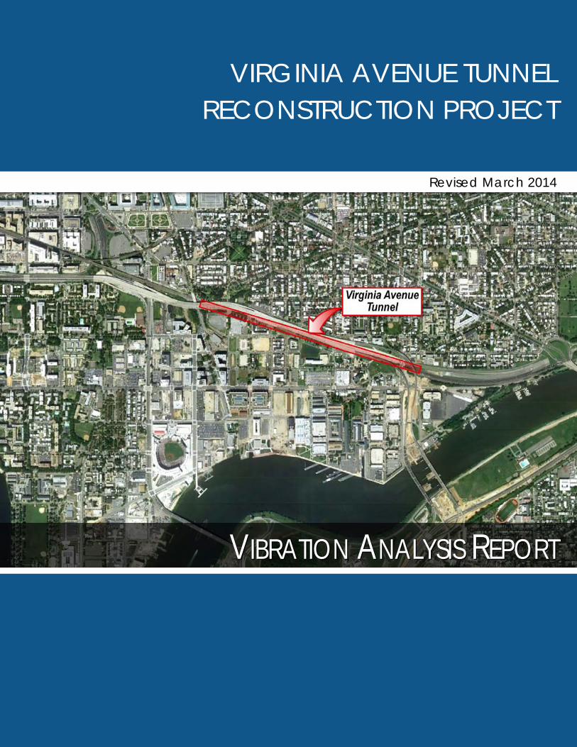
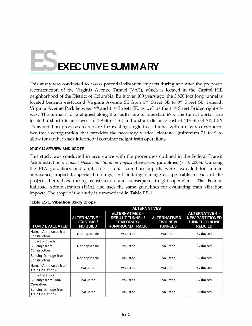
ES EXECUTIVE SUMMARY This study was conducted to assess potential vibration impacts during and after the proposed reconstruction of the Virginia Avenue Tunnel (VAT), which is located in the Capitol Hill neighborhood of the District of Columbia. Built over 100 years ago, the 3,800 foot long tunnel is located beneath eastbound Virginia Avenue SE from 2nd Street SE to 9th Street SE; beneath Virginia Avenue Park between 9th and 11th Streets SE; as well as the 11th Street Bridge right-of-way. The tunnel is also aligned along the south side of Interstate 695. The tunnel portals are located a short distance west of 2nd Street SE and a short distance east of 11th Street SE. CSX Transportation proposes to replace the existing single-track tunnel with a newly constructed two-track configuration that provides the necessary vertical clearance (minimum 21 feet) to allow for double-stack intermodal container freight train operations.
STUDY OVERVIEW AND SCOPE This study was conducted in accordance with the procedures outlined in the Federal Transit Administration’s Transit Noise and Vibration Impact Assessment guidelines (FTA 2006). Utilizing the FTA guidelines and applicable criteria, vibration impacts were evaluated for human annoyance, impact to special buildings, and building damage as applicable to each of the project alternatives during construction and subsequent freight operations. The Federal Railroad Administration (FRA) also uses the same guidelines for evaluating train vibration impacts. The scope of the study is summarized in Table ES-1.
Table ES-1. Vibration Study Scope
TOPIC EVALUATED
ALTERNATIVES
ALTERNATIVE 1 –EXISTING / NO BUILD
ALTERNATIVE 2 –REBUILT TUNNEL /
TEMPORARY RUNAROUND TRACK
ALTERNATIVE 3 – TWO NEW TUNNELS
ALTERNATIVE 4 –NEW PARTITIONED TUNNEL / ONLINE
REBUILD Human Annoyance from Construction
Not applicable Evaluated Evaluated Evaluated
Impact to Special Buildings from Construction
Not applicable Evaluated Evaluated Evaluated
Building Damage from Construction
Not applicable Evaluated Evaluated Evaluated
Human Annoyance from Train Operations
Evaluated Evaluated Evaluated Evaluated
Impact to Special Buildings from Train Operations
Evaluated Evaluated Evaluated Evaluated
Building Damage from Train Operations
Evaluated Evaluated Evaluated Evaluated
Virginia Avenue Tunnel Reconstruction Project
ES-2
“Special Buildings” is an FTA designation for buildings that can be sensitive to vibration. The band practice area at the US Marine Corps facility (Room G62 in Building 25) was evaluated using the FTA “Special Building” criteria as part of this study.
STUDY METHODOLOGY: CONSTRUCTION Vibration during the construction of this project would result primarily from the utilization of specialty construction equipment in the performance of major construction activities such as removal of the existing surface roadway and underground tunnel elements, installation of support of excavation measures, excavation and backfill for the proposed tunnel reconstruction, as well as restoration of the Virginia Avenue roadway and streetscape. Vibration levels produced by construction equipment were obtained from the FTA Transit Noise and Vibration Impact Assessment (FTA 2006). Based on the typical vibration levels for the various pieces of construction equipment anticipated to be used, calculations were performed to determine the distances at which potential vibration impacts could occur during the various construction activities. Distances from the construction activity to nearby buildings were calculated based on the proposed location of each build alternative and the specific construction functions that would need to be performed for that alternative.
The results of these calculations were compared to the FTA Criteria for Human Annoyance, Special Buildings, and Building Damage. For this study a conservative approach was utilized by applying the FTA limit specified for “fragile buildings” to all buildings, regardless of the type and age.
STUDY METHODOLOGY: TRAIN OPERATIONS Existing background and train pass-by vibration levels were measured at 12 sites along the Virginia Avenue Tunnel. Results of these vibration measurements provided data that were used to:
• Determine vibration levels generated by train pass-bys. The highest recorded train vibration level was used as the train vibration source in calculating the impact distances in order to avoid understating future vibration levels.
• Calculate the degree to which the existing tunnel structure reduces vibrations from train pass-bys.
• Calculate the vibration transferability characteristics of the soil.
The measured data was used to depict vibration levels from current train operations at nearby buildings under Alternative 1 (Existing /No Build). Furthermore, this data then served as the basis to predict the potential impacts from train operations for Build Alternatives 2, 3, and 4. The following issues were addressed in this process:
• The centerline of the southernmost track in the proposed tunnel locations for each of the three candidate build alternatives was utilized to determine the distance between the vibration sensitive receptors (buildings and people) and the vibration sources (construction and train operations).
Vibration Analysis Report – Executive Summary
ES-3
• The shallowest tunnel depth adjacent to the sensitive receptors was used for calculating the highest possible vibration levels which would be produced from train operations.
• The proposed maximum operating train speed for the new tunnels of 40 mph was used. This is the most conservative approach which would predict higher vibration levels.
• The proposed track configuration for each of the build alternatives was used, including the elimination of the existing “turnout”, (a transfer point between two tracks) near the east tunnel portal where the single track in the tunnel transitions to a two track configuration.
• Vibration impact predictions assumed two trains were traveling in the tunnel simultaneously.
• Train weight was evaluated and was not modified for assessing vibration impacts during future operations. Locomotives are the heaviest component of a freight train. Changes in locomotive weight or the number of locomotives utilized per train are not anticipated. Replacing the tunnel will introduce double-stacked intermodal container operations to this segment of the rail network. However, historical data for the rail industry clearly indicates that intermodal containers are one of the lightest classes of freight shipped by rail. Trains that are primarily or entirely comprised of double-stacked intermodal containers weigh less than many current trains currently utilizing the Virginia Avenue Tunnel (see Chapter 2 for additional information).
• Reconstruction of the tunnel under any of the candidate build alternatives would include replacing the existing dirt track bed with a 3-foot thick concrete slab. A large mass such as a 3-foot thick reinforced concrete slab will reduce the vibration energy generated by train operations. However, this potential reduction in vibration provided by the reinforced concrete floor was not considered when modeling future vibration levels from train operations under any of the build alternatives. This is a very conservative approach and would predict higher vibration levels than are anticipated with the modern track bed that will be used.
STUDY FINDINGS: GENERAL • The soil vibration transferability characteristics along the entire length of the tunnel are
consistent and predictable at varying distances from the tunnel. This, in combination with the observed geologic features of the area, supports the finding that the calculated vibration transferability characteristics of the soils at the specific data collection sites are applicable along the entire length of the tunnel.
• The degree to which the existing tunnel structure reduces vibration transmission into the surrounding soils from train operations is consistent and likewise predictable along the entire length of the tunnel. This supports the finding that the calculated vibration reductions from the proposed tunnel structure for each build alternative are applicable along the entire length of the tunnel.
• Vibration measurements conducted in May 2012 and December 2013 did not reveal any major differences between tunnel reduction effect and soil transferability characteristics.
Virginia Avenue Tunnel Reconstruction Project
ES-4
• Numerous vibration events were recorded when there were no train operations in the tunnel. Many of these events produced vibration levels that were of equal or greater magnitude than vibration levels generated from train operations. It was beyond the scope of this study to determine the specific nature of the events causing these vibrations. However, neither the frequency nor the magnitudes of these “non-train” vibrations are unusual in an urban environment.
• There was one observed instance in the December 2013 data where a high vibration incident unrelated to train operations occurred during a train passage. This was determined to be a concurrent event by analyzing the vibrations from that same train at other locations along the tunnel. In addition there were numerous additional vibration events not related to train passage that were recorded that were equal or greater than those recorded during train passage.
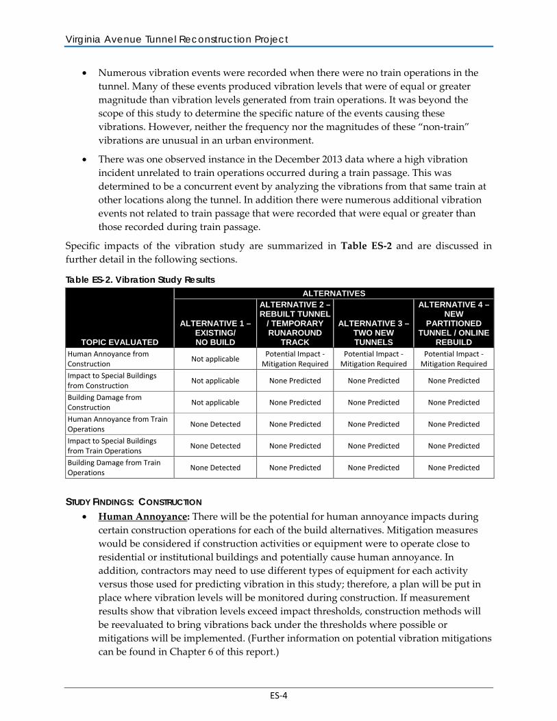
Specific impacts of the vibration study are summarized in Table ES-2 and are discussed in further detail in the following sections.
Table ES-2. Vibration Study Results
TOPIC EVALUATED
ALTERNATIVES
ALTERNATIVE 1 – EXISTING/ NO BUILD
ALTERNATIVE 2 –REBUILT TUNNEL
/ TEMPORARY RUNAROUND
TRACK
ALTERNATIVE 3 – TWO NEW TUNNELS
ALTERNATIVE 4 –NEW
PARTITIONED TUNNEL / ONLINE
REBUILD Human Annoyance from Construction
Not applicable Potential Impact -
Mitigation Required Potential Impact -
Mitigation Required Potential Impact -
Mitigation Required
Impact to Special Buildings from Construction
Not applicable None Predicted None Predicted None Predicted
Building Damage from Construction
Not applicable None Predicted None Predicted None Predicted
Human Annoyance from Train Operations
None Detected None Predicted None Predicted None Predicted
Impact to Special Buildings from Train Operations
None Detected None Predicted None Predicted None Predicted
Building Damage from Train Operations
None Detected None Predicted None Predicted None Predicted
STUDY FINDINGS: CONSTRUCTION • Human Annoyance: There will be the potential for human annoyance impacts during
certain construction operations for each of the build alternatives. Mitigation measures would be considered if construction activities or equipment were to operate close to residential or institutional buildings and potentially cause human annoyance. In addition, contractors may need to use different types of equipment for each activity versus those used for predicting vibration in this study; therefore, a plan will be put in place where vibration levels will be monitored during construction. If measurement results show that vibration levels exceed impact thresholds, construction methods will be reevaluated to bring vibrations back under the thresholds where possible or mitigations will be implemented. (Further information on potential vibration mitigations can be found in Chapter 6 of this report.)
Vibration Analysis Report – Executive Summary
ES-5
• Special Buildings: The Marine Band Practice Hall is considered as an auditorium under the special building category of FTA guidelines. Results of the existing vibration measurements indicated that some of the building internal sources, such as HVAC system are a prevalent source of vibration. Construction or operation vibration impacts are not predicted in the Practice Hall.
• Building Damage: There would be no vibration related building damages due to construction operations under any of the build alternatives.
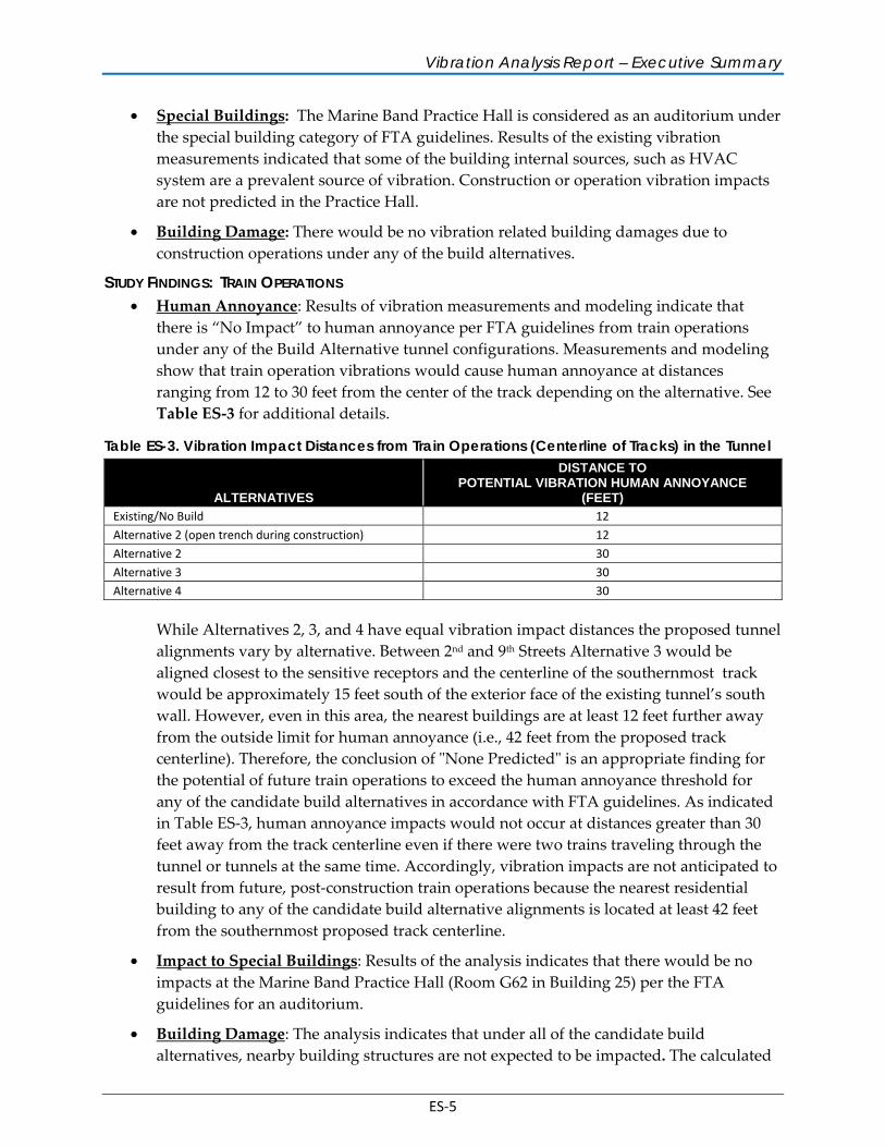
STUDY FINDINGS: TRAIN OPERATIONS • Human Annoyance: Results of vibration measurements and modeling indicate that
there is “No Impact” to human annoyance per FTA guidelines from train operations under any of the Build Alternative tunnel configurations. Measurements and modeling show that train operation vibrations would cause human annoyance at distances ranging from 12 to 30 feet from the center of the track depending on the alternative. See Table ES-3 for additional details.
Table ES-3. Vibration Impact Distances from Train Operations (Centerline of Tracks) in the Tunnel
ALTERNATIVES
DISTANCE TO POTENTIAL VIBRATION HUMAN ANNOYANCE
(FEET) Existing/No Build 12
Alternative 2 (open trench during construction) 12
Alternative 2 30
Alternative 3 30 Alternative 4 30
While Alternatives 2, 3, and 4 have equal vibration impact distances the proposed tunnel alignments vary by alternative. Between 2nd and 9th Streets Alternative 3 would be aligned closest to the sensitive receptors and the centerline of the southernmost track would be approximately 15 feet south of the exterior face of the existing tunnel’s south wall. However, even in this area, the nearest buildings are at least 12 feet further away from the outside limit for human annoyance (i.e., 42 feet from the proposed track centerline). Therefore, the conclusion of "None Predicted" is an appropriate finding for the potential of future train operations to exceed the human annoyance threshold for any of the candidate build alternatives in accordance with FTA guidelines. As indicated in Table ES-3, human annoyance impacts would not occur at distances greater than 30 feet away from the track centerline even if there were two trains traveling through the tunnel or tunnels at the same time. Accordingly, vibration impacts are not anticipated to result from future, post-construction train operations because the nearest residential building to any of the candidate build alternative alignments is located at least 42 feet from the southernmost proposed track centerline.
• Impact to Special Buildings: Results of the analysis indicates that there would be no impacts at the Marine Band Practice Hall (Room G62 in Building 25) per the FTA guidelines for an auditorium.
• Building Damage: The analysis indicates that under all of the candidate build alternatives, nearby building structures are not expected to be impacted. The calculated
Virginia Avenue Tunnel Reconstruction Project
ES-6
impact distance (27 feet from track centerline) for potential building damage vibration is less than the minimum depth from the ground surface to the bottom of the tunnel of 34 feet. Furthermore, the shortest possible path between the vibration source (track center line) and a building structure is 52 feet. Therefore, any building at ground level, even a hypothetical structure located directly above the tunnel, would not be damaged by train operations. (See Figure 5-1 and Table 5-6 in Chapter 5 of this report for further details).
1-1
1 INTRODUCTION
1.1 PURPOSE OF VIBRATION STUDY The purpose of this study is to evaluate existing and assess future vibration levels at sensitive locations along the Virginia Avenue Tunnel (VAT) Reconstruction Project. This report was updated in order to reflect comments and input received from the Federal Highway Administration (FHWA), District Department of Transportation (DDOT), other governmental agencies and the public. Additional vibration tests were conducted in December 2013 to characterize the existing vibration levels at several of the buildings closest to the proposed project during a typical 24 hour period and results were used to further refine the predicted vibration affects from the proposed project.
The study results are described in six sections. Chapter 1 presents the Virginia Avenue Tunnel project description. Chapter 2 explains general vibration terminology. Chapter 3 presents the guidelines and criteria used to assess the potential vibration impacts. Chapter 4 presents the results of baseline vibration measurements. Chapter 5 analyzes the potential impacts of construction and future train operations through the tunnel. Chapter 6 discusses possible mitigation measures that could be implemented to reduce potential vibration impacts of the proposed project.
1.2 PROJECT DESCRIPTION CSX Transportation, Inc. (CSX) is proposing to reconstruct the Virginia Avenue Tunnel. The tunnel is located in the Capitol Hill neighborhood of the District of Columbia, as shown in Figure 1-1. The existing tunnel is 3,800 feet in length and aligned along the south side of Interstate 695 (I-695), located beneath eastbound Virginia Avenue SE from 2nd Street SE to 9th Street SE; Virginia Avenue Park between 9th and 11th Streets SE; and the 11th Street Bridge right-of-way. The tunnel portals are located a short distance west of 2nd Street SE and a short distance east of 11th Street SE. The tunnel is an integral part of CSX’s freight rail network that encompasses approximately 21,000 miles of railroad track in the District, 23 states, and the Canadian provinces of Ontario and Quebec. Specifically, the tunnel is located along CSX’s eastern seaboard freight rail corridor, which stretches from the southeast through the Mid-Atlantic and connecting to the Midwest, thereby making it a key link in the nation’s network of major freight rail lines.
If the Virginia Avenue Tunnel were not replaced or reconstructed, it will continue to require increasingly higher levels of investment for maintenance and repair, resulting in more frequent service interruptions and higher risks for localized disturbances. In addition, the tunnel has notable operational deficiencies. Specifically, the tunnel has just a single railroad track, which limits the flow of freight train traffic. Virginia Avenue Tunnel was identified as a bottleneck on the east coast (District of Columbia Freight Forum, Volume 1, Issue 1 [January 2012]). Furthermore, the tunnel does not have sufficient vertical clearance to accommodate rail cars that are loaded with two intermodal containers set one on top of the other, which is called
Virginia Avenue Tunnel Reconstruction Project
1-2
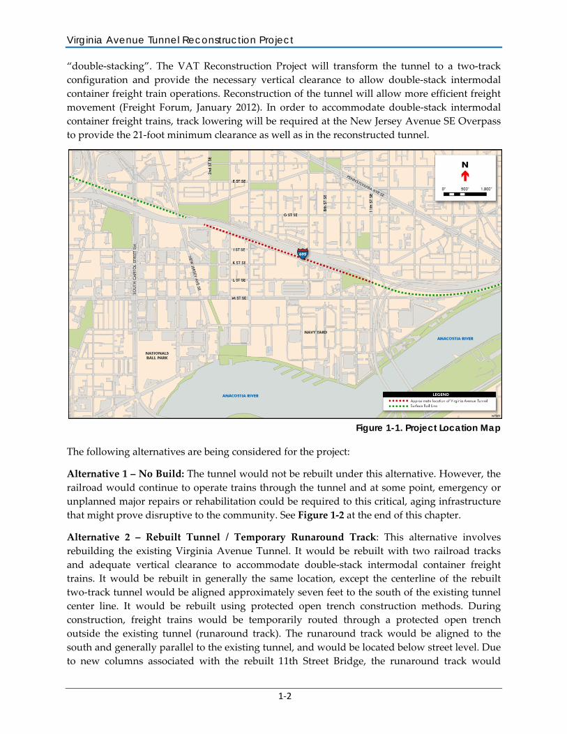
“double-stacking”. The VAT Reconstruction Project will transform the tunnel to a two-track configuration and provide the necessary vertical clearance to allow double-stack intermodal container freight train operations. Reconstruction of the tunnel will allow more efficient freight movement (Freight Forum, January 2012). In order to accommodate double-stack intermodal container freight trains, track lowering will be required at the New Jersey Avenue SE Overpass to provide the 21-foot minimum clearance as well as in the reconstructed tunnel.
Figure 1-1. Project Location Map
The following alternatives are being considered for the project:
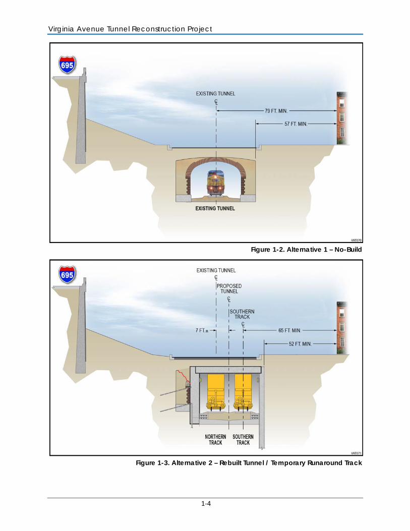
Alternative 1 – No Build: The tunnel would not be rebuilt under this alternative. However, the railroad would continue to operate trains through the tunnel and at some point, emergency or unplanned major repairs or rehabilitation could be required to this critical, aging infrastructure that might prove disruptive to the community. See Figure 1-2 at the end of this chapter.
Alternative 2 – Rebuilt Tunnel / Temporary Runaround Track: This alternative involves rebuilding the existing Virginia Avenue Tunnel. It would be rebuilt with two railroad tracks and adequate vertical clearance to accommodate double-stack intermodal container freight trains. It would be rebuilt in generally the same location, except the centerline of the rebuilt two-track tunnel would be aligned approximately seven feet to the south of the existing tunnel center line. It would be rebuilt using protected open trench construction methods. During construction, freight trains would be temporarily routed through a protected open trench outside the existing tunnel (runaround track). The runaround track would be aligned to the south and generally parallel to the existing tunnel, and would be located below street level. Due to new columns associated with the rebuilt 11th Street Bridge, the runaround track would
Vibration Analysis Report – Introduction
1-3
slightly separate from the tunnel alignment on the east end starting just west of Virginia Avenue Park. Safety measures such as securing fencing would be used to prevent pedestrians and cyclists from accessing the runaround track. See Figure 1-3 at the end of this chapter.
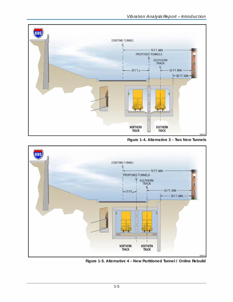
Alternative 3 – Two New Tunnels: This alternative involves replacing the existing Virginia Avenue Tunnel with two new permanent tunnels constructed sequentially. Each new tunnel would have a single railroad track with enough vertical clearance to allow double-stack intermodal container freight trains. A new parallel south side tunnel would be built first as trains continue operating in the existing Virginia Avenue Tunnel. This tunnel would be built using protected open trench construction methods. After the south side tunnel is completed, train operations would switch over to the new tunnel and the existing Virginia Avenue Tunnel would be demolished and rebuilt. With the exception of operating in a protected open trench for approximately 230 feet immediately east of the 2nd Street SE portal (within the Virginia Avenue SE segment between 2nd and 3rd Streets SE), trains would operate in enclosed tunnels throughout construction under Alternative 3. Throughout most of the length of the rebuilt tunnel, the two tunnels would be separated by a center wall. This center wall would be the new centerline of the two tunnels, and it would be aligned approximately 25 feet south of the existing tunnel centerline, between 2nd and 9th Streets SE. Due to new columns associated with the rebuilt 11th Street Bridge, the tunnels would be separated on the east end starting just west of Virginia Avenue Park, resulting in two separate single-track tunnels and openings at the east portal. See Figure 1-4 at the end of this chapter.
Alternative 4 – New Partitioned Tunnel / Online Rebuild: Alternative 4 would result in a new tunnel with two permanent tracks. Similar to Alternative 3, the new tunnel would be partitioned and have enough vertical clearance to allow double-stack intermodal container freight trains. It would be aligned approximately 17 feet south of the existing tunnel’s centerline. The new tunnel would be built using protected open trench construction methods. The rebuild would occur ‘online’, meaning that during the period of construction, the protected open trench would accommodate both construction activities and train operations. Maintaining safe and reliable temporary train operations is a more complicated endeavor under Alternative 4 than under the other two Build Alternatives because of the online rebuild approach. See Figure 1-5 at the end of this chapter.
Under all candidate build alternatives, the total length of the rebuilt Virginia Avenue Tunnel will be extended by approximately 330 feet on the east end. The new east tunnel portal will be located northeast of the existing M Street SE / 12th Street SE T-intersection.
Virginia Avenue Tunnel Reconstruction Project
1-4
Figure 1-2. Alternative 1 – No-Build
Figure 1-3. Alternative 2 – Rebuilt Tunnel / Temporary Runaround Track
Vibration Analysis Report – Introduction
1-5
Figure 1-4. Alternative 3 – Two New Tunnels
Figure 1-5. Alternative 4 – New Partitioned Tunnel / Online Rebuild
2-1
2 VIBRATION BACKGROUND
This section describes the basic concepts and general terminology of vibration and provides background for the assessment procedures described in the later sections.
Vibration is an oscillatory motion that can be described in terms of displacement, velocity, or acceleration. Displacement, in the case of a vibrating floor, is simply the distance that a point on the floor moves away from its static position. The velocity represents the instantaneous speed of the floor movement, and acceleration is the rate of change of the speed. The response of humans, buildings, and equipment to vibration is normally described using velocity or acceleration. In this report, velocity will be used to describe ground-borne vibration.
Vibration amplitudes are usually expressed as either peak particle velocity (PPV) or the root mean square (RMS) velocity. The PPV is defined as the maximum instantaneous peak of the vibration signal in inches per second. The RMS of a signal is the average of the squared amplitude of the signal in inches per second. Although PPV is appropriate for evaluating the potential of building damage, it is not suitable for evaluating human response. Since it takes some time for the human body to respond to vibration signals, RMS amplitude is more appropriate to evaluate human response to vibration than PPV.
The Federal Transit Administration (FTA), a division of the U.S. Department of Transportation (USDOT), uses the abbreviation “VdB” for vibration decibels (FTA, 2006) to reduce the potential for confusion with sound decibel. When determining the VdB level for vibration sources such as trains, first a conversion factor of 4 is applied to the measured PPV value to obtain the RMS value. This conversion number is known as the crest factor and is the ratio between the PPV amplitude and the RMS amplitude. Next, the RMS vibration value is logarithmically adjusted against the reference value of 1 micro-inch per second and multiplied by 20 to be expressed in VdB values used throughout this report and shown as the following equation: = 20 10( )
Where: v = PPV/4 and vref = 1× 10⁻⁶ in/sec
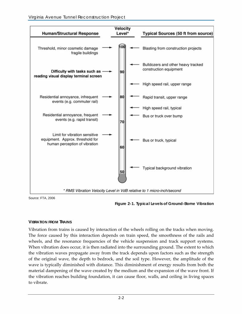
Figure 2-1 illustrates common vibration sources and the corresponding human and structural response to the associated ground-borne vibration. As shown in the figure, the threshold of perception for human response is approximately 65 VdB; however, human response to vibration is not usually significant unless the vibration exceeds 70 VdB.
Virginia Avenue Tunnel Reconstruction Project
2-2
Source: FTA, 2006
Figure 2-1. Typical Levels of Ground-Borne Vibration
VIBRATION FROM TRAINS Vibration from trains is caused by interaction of the wheels rolling on the tracks when moving. The force caused by this interaction depends on train speed, the smoothness of the rails and wheels, and the resonance frequencies of the vehicle suspension and track support systems. When vibration does occur, it is then radiated into the surrounding ground. The extent to which the vibration waves propagate away from the track depends upon factors such as the strength of the original wave, the depth to bedrock, and the soil type. However, the amplitude of the wave is typically diminished with distance. This diminishment of energy results from both the material dampening of the wave created by the medium and the expansion of the wave front. If the vibration reaches building foundation, it can cause floor, walls, and ceiling in living spaces to vibrate.
Vibration Analysis Report – Vibration Background
2-3
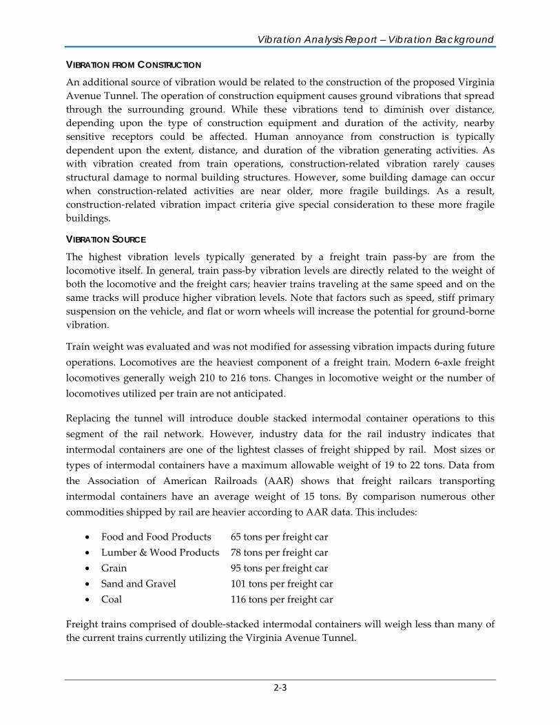
VIBRATION FROM CONSTRUCTION An additional source of vibration would be related to the construction of the proposed Virginia Avenue Tunnel. The operation of construction equipment causes ground vibrations that spread through the surrounding ground. While these vibrations tend to diminish over distance, depending upon the type of construction equipment and duration of the activity, nearby sensitive receptors could be affected. Human annoyance from construction is typically dependent upon the extent, distance, and duration of the vibration generating activities. As with vibration created from train operations, construction-related vibration rarely causes structural damage to normal building structures. However, some building damage can occur when construction-related activities are near older, more fragile buildings. As a result, construction-related vibration impact criteria give special consideration to these more fragile buildings.
VIBRATION SOURCE The highest vibration levels typically generated by a freight train pass-by are from the locomotive itself. In general, train pass-by vibration levels are directly related to the weight of both the locomotive and the freight cars; heavier trains traveling at the same speed and on the same tracks will produce higher vibration levels. Note that factors such as speed, stiff primary suspension on the vehicle, and flat or worn wheels will increase the potential for ground-borne vibration.
Train weight was evaluated and was not modified for assessing vibration impacts during future operations. Locomotives are the heaviest component of a freight train. Modern 6-axle freight locomotives generally weigh 210 to 216 tons. Changes in locomotive weight or the number of locomotives utilized per train are not anticipated.
Replacing the tunnel will introduce double stacked intermodal container operations to this segment of the rail network. However, industry data for the rail industry indicates that intermodal containers are one of the lightest classes of freight shipped by rail. Most sizes or types of intermodal containers have a maximum allowable weight of 19 to 22 tons. Data from the Association of American Railroads (AAR) shows that freight railcars transporting intermodal containers have an average weight of 15 tons. By comparison numerous other commodities shipped by rail are heavier according to AAR data. This includes:
• Food and Food Products 65 tons per freight car • Lumber & Wood Products 78 tons per freight car • Grain 95 tons per freight car • Sand and Gravel 101 tons per freight car • Coal 116 tons per freight car
Freight trains comprised of double-stacked intermodal containers will weigh less than many of the current trains currently utilizing the Virginia Avenue Tunnel.
Virginia Avenue Tunnel Reconstruction Project
2-4
The length of the train is not a major factor when evaluating possible building damage. However, while peak vibration intensity is typically not higher for longer trains, they can cause greater annoyance due to the duration of the event.
Finally, the height of the freight car also does not directly influence the vibration intensity; double-stack freight cars do not produce higher vibrations just because they are carrying two containers.
3-1
3 IMPACT CRITERIA
This section presents the guidelines, criteria, and regulations that were used to assess vibration impacts associated with the proposed project. The District of Columbia Department of Transportation (DDOT) environmental regulations do not address potential vibration impacts; therefore, the criteria in the FTA Transit Noise and Vibration Impact Assessment (FTA 2006) were used to evaluate vibration impacts from tunnel construction and train operations. The evaluation of vibration impacts can be divided into two categories: (1) human annoyance and (2) building damage.
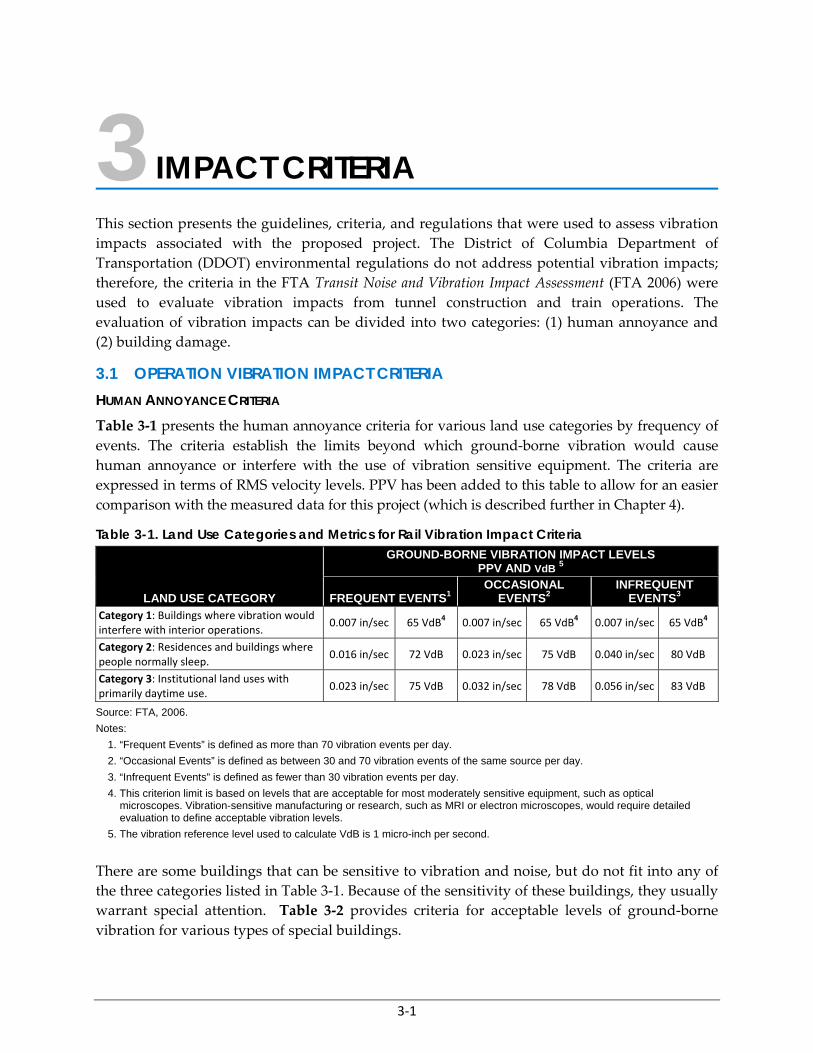
3.1 OPERATION VIBRATION IMPACT CRITERIA HUMAN ANNOYANCE CRITERIA Table 3-1 presents the human annoyance criteria for various land use categories by frequency of events. The criteria establish the limits beyond which ground-borne vibration would cause human annoyance or interfere with the use of vibration sensitive equipment. The criteria are expressed in terms of RMS velocity levels. PPV has been added to this table to allow for an easier comparison with the measured data for this project (which is described further in Chapter 4).
Table 3-1. Land Use Categories and Metrics for Rail Vibration Impact Criteria
LAND USE CATEGORY
GROUND-BORNE VIBRATION IMPACT LEVELSPPV AND VdB 5
FREQUENT EVENTS1OCCASIONAL
EVENTS2 INFREQUENT
EVENTS3
Category 1: Buildings where vibration would interfere with interior operations.
0.007 in/sec 65 VdB4 0.007 in/sec 65 VdB4 0.007 in/sec 65 VdB4
Category 2: Residences and buildings where people normally sleep.
0.016 in/sec 72 VdB 0.023 in/sec 75 VdB 0.040 in/sec 80 VdB
Category 3: Institutional land uses with primarily daytime use.
0.023 in/sec 75 VdB 0.032 in/sec 78 VdB 0.056 in/sec 83 VdB
Source: FTA, 2006.
Notes:
1. “Frequent Events” is defined as more than 70 vibration events per day.
2. “Occasional Events” is defined as between 30 and 70 vibration events of the same source per day.
3. “Infrequent Events” is defined as fewer than 30 vibration events per day.
4. This criterion limit is based on levels that are acceptable for most moderately sensitive equipment, such as optical microscopes. Vibration-sensitive manufacturing or research, such as MRI or electron microscopes, would require detailed evaluation to define acceptable vibration levels.
5. The vibration reference level used to calculate VdB is 1 micro-inch per second.
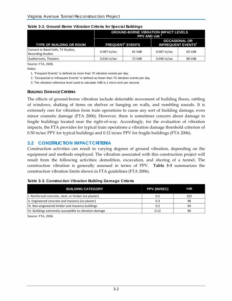
There are some buildings that can be sensitive to vibration and noise, but do not fit into any of the three categories listed in Table 3-1. Because of the sensitivity of these buildings, they usually warrant special attention. Table 3-2 provides criteria for acceptable levels of ground-borne vibration for various types of special buildings.
Virginia Avenue Tunnel Reconstruction Project
3-2
Table 3-2. Ground-Borne Vibration Criteria for Special Buildings
TYPE OF BUILDING OR ROOM
GROUND-BORNE VIBRATION IMPACT LEVELSPPV AND VdB 3
FREQUENT1 EVENTS OCCASIONAL OR
INFREQUENT EVENTS2 Concert or Band Halls, TV Studios, Recording Studios
0.007 in/sec 65 VdB 0.007 in/sec 65 VdB
Auditoriums, Theaters 0.016 in/sec 72 VdB 0.040 in/sec 80 VdB
Source: FTA, 2006.
Notes:
1. “Frequent Events” is defined as more than 70 vibration events per day.
2. "Occasional or Infrequent Events" is defined as fewer than 70 vibration events per day.
3. The vibration reference level used to calculate VdB is 1 micro-inch per second.
BUILDING DAMAGE CRITERIA The effects of ground-borne vibration include detectable movement of building floors, rattling of windows, shaking of items on shelves or hanging on walls, and rumbling sounds. It is extremely rare for vibration from train operations to cause any sort of building damage, even minor cosmetic damage (FTA 2006). However, there is sometimes concern about damage to fragile buildings located near the right-of-way. Accordingly, for the evaluation of vibration impacts, the FTA provides for typical train operations a vibration damage threshold criterion of 0.50 in/sec PPV for typical buildings and 0.12 in/sec PPV for fragile buildings (FTA 2006).
3.2 CONSTRUCTION IMPACT CRITERIA Construction activities can result in varying degrees of ground vibration, depending on the equipment and methods employed. The vibration associated with this construction project will result from the following activities: demolition, excavation, and shoring of a tunnel. The construction vibration is generally assessed in terms of PPV. Table 3-3 summarizes the construction vibration limits shown in FTA guidelines (FTA 2006).
Table 3-3. Construction Vibration Building Damage Criteria
BUILDING CATEGORY PPV (IN/SEC) VdB
I. Reinforced-concrete, steel, or timber (no plaster) 0.5 102
II. Engineered concrete and masonry (no plaster) 0.3 98
III. Non-engineered timber and masonry buildings 0.2 94 IV. Buildings extremely susceptible to vibration damage 0.12 90
Source: FTA, 2006.
4-1
4 EXISTING SETTING AND MEASUREMENT METHODOLOGY
4.1 EXISTING LAND USE All of the candidate build alternatives would replace the existing 3,800-foot tunnel underneath Virginia Avenue SE, and include an additional 330-foot extension for the proposed location of the new east portal providing further protection to vibration sensitive land use areas and buildings currently located to the west of the existing portal location. For the purpose of this study, vibration sensitive receptors were selected based on their proximity to the three candidate build alternative alignments and based on existing land use, as described in the following paragraphs.
The Southeast/Southwest Freeway (I-695), located on the north side of the VAT, serves as a "barrier" that creates a discontinuity in vibration path from the proposed project to any sensitive receptors located to the north of the freeway. As a result there will be no vibration impacts from the construction or the trains operations of the proposed project at any of the buildings located north of I-695.
The following is a list of potentially vibration sensitive buildings from east to west that are located south of the proposed project and could be affected by the construction and/or by train operation vibrations:
• 809 Virginia Avenue - office building
• Marine Barracks, which includes the Enlisted Men’s Quarters and the Marine Band Practice Hall - residential/special building (auditorium)
• Capper Senior Apartments – residential
• St. Paul African Union Methodist Protestant Church - institutional
• Capitol Quarter Townhomes – residential
• 200 I Street - institutional
There are other residential buildings as well as schools, hospitals, religious organizations, and similar institutions in the project vicinity but they are further away from the proposed project limits than the facilities noted above. Figures 2 through 4 in Appendix A show the location of the proposed Alternative 3 tunnel and the nearby buildings; these represent the condition with the closest track alignment adjacent to the sensitive receptors.
4.2 VIBRATION MEASUREMENT METHODOLOGY Vibration measurements were conducted to determine baseline vibration levels from existing train pass-bys and to calculate vibration transferability characteristics of the soil for the purpose
Virginia Avenue Tunnel Reconstruction Project
4-2
of projecting expected vibration levels during construction and from train operations. Vibration propagation is highly dependent on the soil, discontinuities in the path by which vibration travels, and the type of building foundation. Measuring the vibration levels from trains passing through the existing tunnel provides the most definitive information on how vibration is propagated in the surrounding area of the project.
The purpose of the measurements was to determine the force generated by train pass-bys, calculate soil vibration transferability characteristics, and predict tunnel vibration reduction effects. Measurements conducted near the east portal were the closest locations to the tracks where the strongest vibration signal could be measured without interference from the tunnel or other obstructions. Results of these measurements were suitable for calculating the soil vibration transferability characteristics and determining the highest train pass-by vibration level. Using the soil factor and train generated vibration levels, vibration effects could be calculated at various measurement sites near the tunnel. Therefore, differences between the measured and calculated vibration levels at a given site will provide the amount of the vibration reduction provided by the tunnel at that location. Knowing the vibration created by a train pass-by, soil factor, and tunnel vibration reduction amount, vibration levels can be predicted from the future tunnel at different locations.
Measurements were conducted near the tunnel on two separate occasions: between May 22 and 23, 2012 and between December 19 and 20, 2013. The vibration measurements were conducted using GeoSonic 3000EZ Plus and 3000LC portable seismographs. Vibration levels were measured on the vertical, transverse, and longitudinal axes and recorded as PPV vibrations (in inches per second). The seismograph includes an internal calibration sequence and was operated according to the manufacturer’s specifications. Vibration measurements were conducted by Parsons staff.
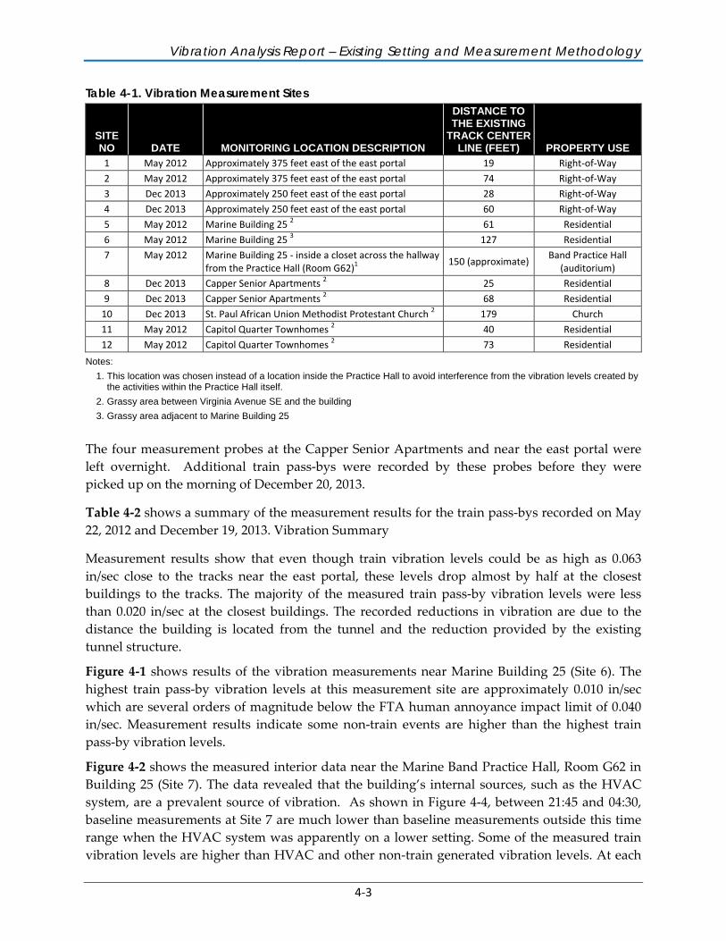
Table 4-1 presents the list of measurement sites and Figure 1 in Appendix A shows the general location of the sites. Figures 2 through 4 in Appendix A show the measurement sites overlaid on an aerial background with the Alternative 3 track alignments and the nearby buildings. Note that Alternative 3 represents the condition with the closest track alignment to adjacent sensitive receptors.
Vibration levels at each location were measured for at least five train pass-bys. During each measurement, the speed of the train was recorded near the east portal using a radar gun and the number of locomotives as well as number of cars was recorded for each train. Baseline vibration levels collected just before and after each train pass-by during the day at each site were also recorded at each measurement site.
Three measurement probes were left overnight at the Marine Building 25 and Band Practice Hall (Room G62 in Building 25) locations because it was not feasible to gain access to them during the afternoon. Additional train pass-bys were recorded by the two probes outside of Marine Building 25 and the one probe near the Practice Hall before they were picked up on the morning of May 23, 2012.
Vibration Analysis Report – Existing Setting and Measurement Methodology
4-3
Table 4-1. Vibration Measurement Sites
SITE NO DATE MONITORING LOCATION DESCRIPTION
DISTANCE TO THE EXISTING
TRACK CENTER LINE (FEET) PROPERTY USE
1 May 2012 Approximately 375 feet east of the east portal 19 Right-of-Way
2 May 2012 Approximately 375 feet east of the east portal 74 Right-of-Way 3 Dec 2013 Approximately 250 feet east of the east portal 28 Right-of-Way
4 Dec 2013 Approximately 250 feet east of the east portal 60 Right-of-Way
5 May 2012 Marine Building 25 2 61 Residential
6 May 2012 Marine Building 25 3 127 Residential
7 May 2012 Marine Building 25 - inside a closet across the hallway from the Practice Hall (Room G62)1
150 (approximate) Band Practice Hall
(auditorium) 8 Dec 2013 Capper Senior Apartments 2 25 Residential
9 Dec 2013 Capper Senior Apartments 2 68 Residential
10 Dec 2013 St. Paul African Union Methodist Protestant Church 2 179 Church
11 May 2012 Capitol Quarter Townhomes 2 40 Residential
12 May 2012 Capitol Quarter Townhomes 2 73 Residential
Notes:
1. This location was chosen instead of a location inside the Practice Hall to avoid interference from the vibration levels created by the activities within the Practice Hall itself.
2. Grassy area between Virginia Avenue SE and the building
3. Grassy area adjacent to Marine Building 25
The four measurement probes at the Capper Senior Apartments and near the east portal were left overnight. Additional train pass-bys were recorded by these probes before they were picked up on the morning of December 20, 2013.
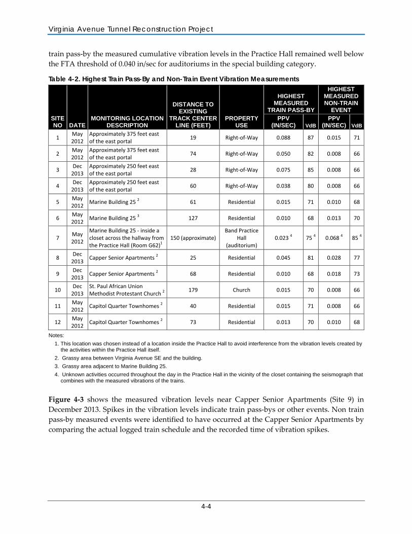
Table 4-2 shows a summary of the measurement results for the train pass-bys recorded on May 22, 2012 and December 19, 2013. Vibration Summary
Measurement results show that even though train vibration levels could be as high as 0.063 in/sec close to the tracks near the east portal, these levels drop almost by half at the closest buildings to the tracks. The majority of the measured train pass-by vibration levels were less than 0.020 in/sec at the closest buildings. The recorded reductions in vibration are due to the distance the building is located from the tunnel and the reduction provided by the existing tunnel structure.
Figure 4-1 shows results of the vibration measurements near Marine Building 25 (Site 6). The highest train pass-by vibration levels at this measurement site are approximately 0.010 in/sec which are several orders of magnitude below the FTA human annoyance impact limit of 0.040 in/sec. Measurement results indicate some non-train events are higher than the highest train pass-by vibration levels.
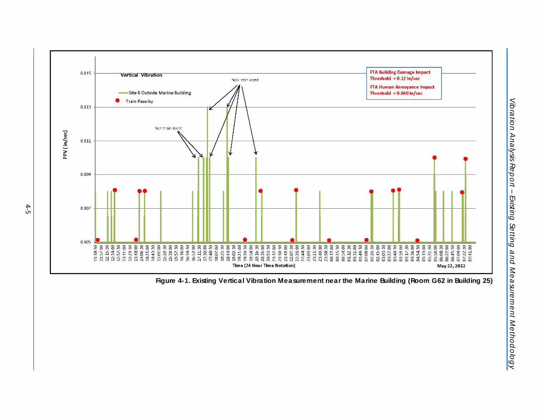
Figure 4-2 shows the measured interior data near the Marine Band Practice Hall, Room G62 in Building 25 (Site 7). The data revealed that the building’s internal sources, such as the HVAC system, are a prevalent source of vibration. As shown in Figure 4-4, between 21:45 and 04:30, baseline measurements at Site 7 are much lower than baseline measurements outside this time range when the HVAC system was apparently on a lower setting. Some of the measured train vibration levels are higher than HVAC and other non-train generated vibration levels. At each
Virginia Avenue Tunnel Reconstruction Project
4-4
train pass-by the measured cumulative vibration levels in the Practice Hall remained well below the FTA threshold of 0.040 in/sec for auditoriums in the special building category.
Table 4-2. Highest Train Pass-By and Non-Train Event Vibration Measurements
SITE NO DATE
MONITORING LOCATION DESCRIPTION
DISTANCE TO EXISTING
TRACK CENTER LINE (FEET)
PROPERTY USE
HIGHEST MEASURED
TRAIN PASS-BY
HIGHEST MEASURED NON-TRAIN
EVENT PPV
(IN/SEC) VdB PPV
(IN/SEC) VdB
1 May 2012
Approximately 375 feet east of the east portal
19 Right-of-Way 0.088 87 0.015 71
2 May 2012
Approximately 375 feet east of the east portal
74 Right-of-Way 0.050 82 0.008 66
3 Dec
2013 Approximately 250 feet east of the east portal
28 Right-of-Way 0.075 85 0.008 66
4 Dec
2013 Approximately 250 feet east of the east portal
60 Right-of-Way 0.038 80 0.008 66
5 May 2012
Marine Building 25 2 61 Residential 0.015 71 0.010 68
6 May 2012
Marine Building 25 3 127 Residential 0.010 68 0.013 70
7 May 2012
Marine Building 25 - inside a closet across the hallway from the Practice Hall (Room G62)1
150 (approximate) Band Practice
Hall (auditorium)
0.023 4 75 4 0.068 4 85 4
8 Dec
2013 Capper Senior Apartments 2 25 Residential 0.045 81 0.028 77
9 Dec
2013 Capper Senior Apartments 2 68 Residential 0.010 68 0.018 73
10 Dec
2013 St. Paul African Union Methodist Protestant Church 2
179 Church 0.015 70 0.008 66
11 May 2012
Capitol Quarter Townhomes 2 40 Residential 0.015 71 0.008 66
12 May 2012
Capitol Quarter Townhomes 2 73 Residential 0.013 70 0.010 68
Notes:
1. This location was chosen instead of a location inside the Practice Hall to avoid interference from the vibration levels created by the activities within the Practice Hall itself.
2. Grassy area between Virginia Avenue SE and the building.
3. Grassy area adjacent to Marine Building 25.
4. Unknown activities occurred throughout the day in the Practice Hall in the vicinity of the closet containing the seismograph that combines with the measured vibrations of the trains.
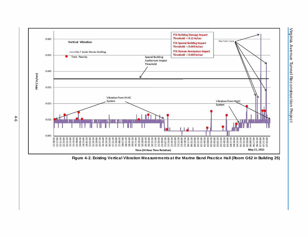
Figure 4-3 shows the measured vibration levels near Capper Senior Apartments (Site 9) in December 2013. Spikes in the vibration levels indicate train pass-bys or other events. Non train pass-by measured events were identified to have occurred at the Capper Senior Apartments by comparing the actual logged train schedule and the recorded time of vibration spikes.
Vibration A
nalysis Report – Existing Setting and M
easurement M
ethodology
4-5
Figure 4-1. Existing Vertical Vibration Measurement near the Marine Building (Room G62 in Building 25)
Virginia A
venue Tunnel Reconstruction Project
4-6
Figure 4-2. Existing Vertical Vibration Measurements at the Marine Band Practice Hall (Room G62 in Building 25)
Vibration A
nalysis Report – Existing Setting and M
easurement M
ethodology
4-7
Figure 4-3. Existing Vertical Vibration Measurements near Capper Senior Apartments
Virginia Avenue Tunnel Reconstruction Project
4-8
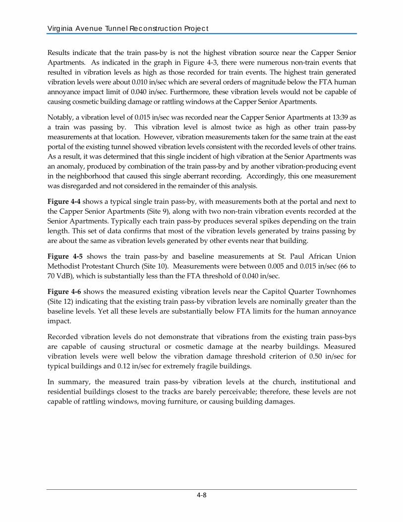
Results indicate that the train pass-by is not the highest vibration source near the Capper Senior Apartments. As indicated in the graph in Figure 4-3, there were numerous non-train events that resulted in vibration levels as high as those recorded for train events. The highest train generated vibration levels were about 0.010 in/sec which are several orders of magnitude below the FTA human annoyance impact limit of 0.040 in/sec. Furthermore, these vibration levels would not be capable of causing cosmetic building damage or rattling windows at the Capper Senior Apartments.
Notably, a vibration level of 0.015 in/sec was recorded near the Capper Senior Apartments at 13:39 as a train was passing by. This vibration level is almost twice as high as other train pass-by measurements at that location. However, vibration measurements taken for the same train at the east portal of the existing tunnel showed vibration levels consistent with the recorded levels of other trains. As a result, it was determined that this single incident of high vibration at the Senior Apartments was an anomaly, produced by combination of the train pass-by and by another vibration-producing event in the neighborhood that caused this single aberrant recording. Accordingly, this one measurement was disregarded and not considered in the remainder of this analysis.
Figure 4-4 shows a typical single train pass-by, with measurements both at the portal and next to the Capper Senior Apartments (Site 9), along with two non-train vibration events recorded at the Senior Apartments. Typically each train pass-by produces several spikes depending on the train length. This set of data confirms that most of the vibration levels generated by trains passing by are about the same as vibration levels generated by other events near that building.
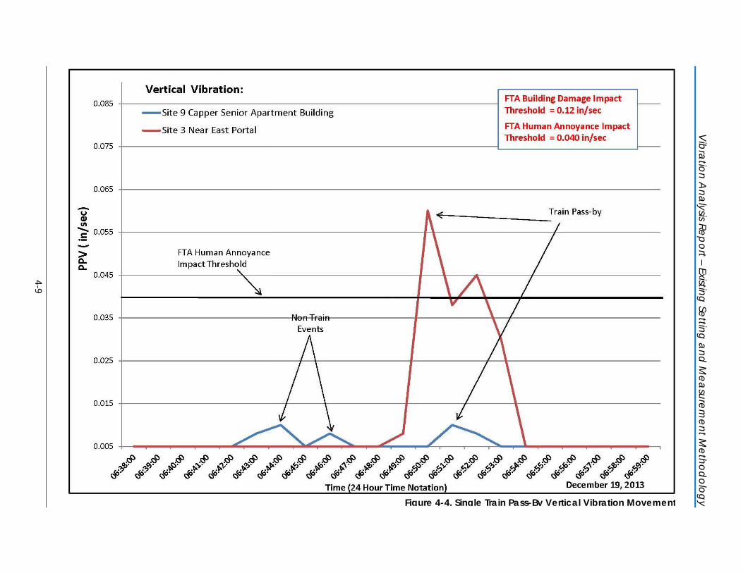
Figure 4-5 shows the train pass-by and baseline measurements at St. Paul African Union Methodist Protestant Church (Site 10). Measurements were between 0.005 and 0.015 in/sec (66 to 70 VdB), which is substantially less than the FTA threshold of 0.040 in/sec.
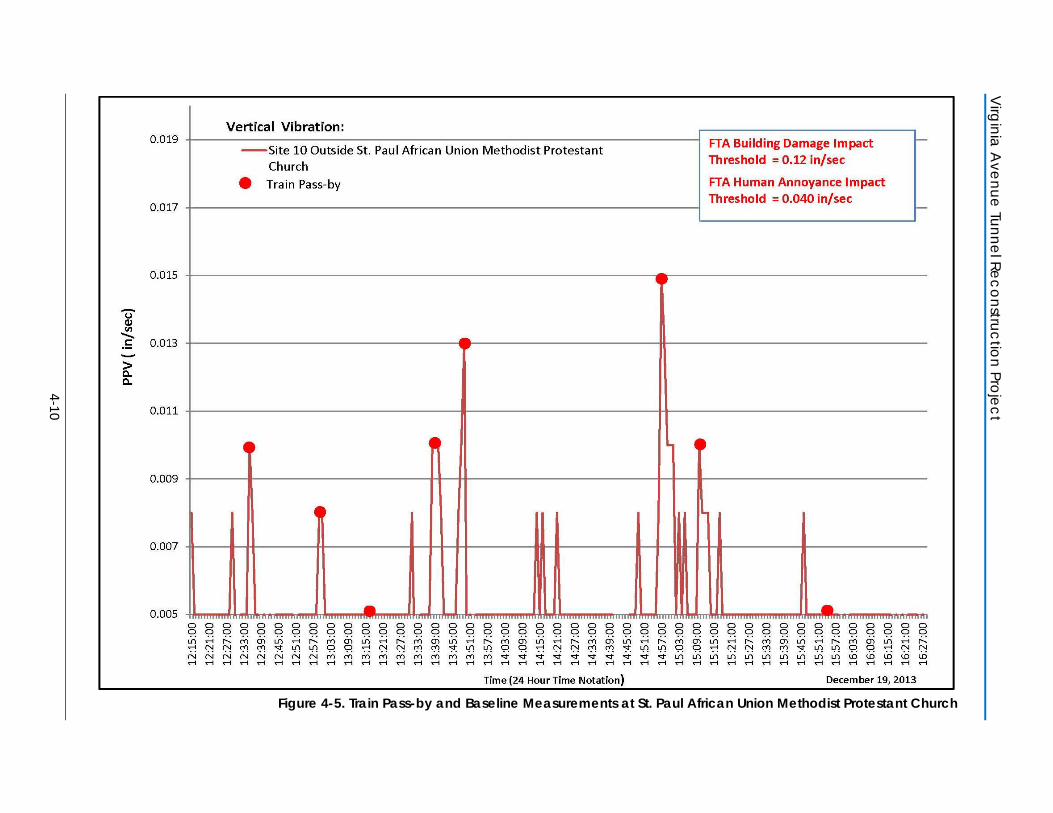
Figure 4-6 shows the measured existing vibration levels near the Capitol Quarter Townhomes (Site 12) indicating that the existing train pass-by vibration levels are nominally greater than the baseline levels. Yet all these levels are substantially below FTA limits for the human annoyance impact.
Recorded vibration levels do not demonstrate that vibrations from the existing train pass-bys are capable of causing structural or cosmetic damage at the nearby buildings. Measured vibration levels were well below the vibration damage threshold criterion of 0.50 in/sec for typical buildings and 0.12 in/sec for extremely fragile buildings.
In summary, the measured train pass-by vibration levels at the church, institutional and residential buildings closest to the tracks are barely perceivable; therefore, these levels are not capable of rattling windows, moving furniture, or causing building damages.
Vibration A
nalysis Report – Existing Setting and M
easurement M
ethodology
4-9
Figure 4-4. Single Train Pass-By Vertical Vibration Movement
Virginia A
venue Tunnel Reconstruction Project
4-10
Figure 4-5. Train Pass-by and Baseline Measurements at St. Paul African Union Methodist Protestant Church
Vibration A
nalysis Report – Existing Setting and M
easurement M
ethodology
4-11
Figure 4-6. Existing Train Pass-By Vertical Vibration Measurements at the Capital Quarter Townhomes
Virginia Avenue Tunnel Reconstruction Project
4-12
4.3 SOIL PROPAGATION CHARACTERISTICS The soil vibration propagation characteristic was calculated by comparing the PPV at different distances from the track. The east portal site was the most suitable location within the project area to measure the train tunnel pass-bys closest to the track; the data at this location is crucial in order to calculate the soil propagation characteristic. Results of measurements conducted in both May 2012 and December 2013 were used for calculating the soil vibration transferability characteristics.
It was determined from geotechnical field investigations conducted in support of the NEPA document by others (Mueser Rutledge Consulting Engineers) that the geology surrounding the proposed project area is similar and that the proposed tunnel base along the alignment would be founded on the same stratum of soils. Therefore, the calculated average soil factor from the measurements conducted near the east portal where they were unaffected by any tunnel structure reducing effects was used for the entire project area.
The vibration wave from the train pass-by dissipates as the wave transfers through the soil between two discrete points. This dissipation rate is dependent on the local soil composition and is called the soil factor in this report. The soil factors at the east portal vibration measurement site were calculated using recorded vibration levels at 30 second intervals for each train pass-by event. These values were then averaged to calculate the soil factor for the surrounding area of the project. Table B-1 in Appendix B contains the data sets that were used to calculate the soil factor.
The vertical-axis results were used for this analysis, as recommended in the FTA manual (FTA 2006), because the vertical vibration is usually transmitted more efficiently into building foundations than transverse or longitudinal vibration.
5-1
5 IMPACT ASSESSMENT Reconstruction of the Virginia Avenue Tunnel was evaluated to determine potential vibration impacts during the reconstruction project and from train operations. The impact assessment presented in this section was conducted in accordance with procedures outlined in FTA’s Transit Noise and Vibration Impact Assessment manual (FTA 2006).
5.1 CONSTRUCTION VIBRATION Two types of potential construction vibration impacts were analyzed: (1) human annoyance and (2) building damage. The potential for human annoyance occurs when construction vibration rises significantly above the threshold of human perception for extended periods of time. Building damage can be cosmetic or structural. As a general matter, fragile buildings such as older masonry structures have a greater potential to be susceptible to damage from ground vibration than buildings that are not particularly fragile (see Table 3-3 in Chapter 3).
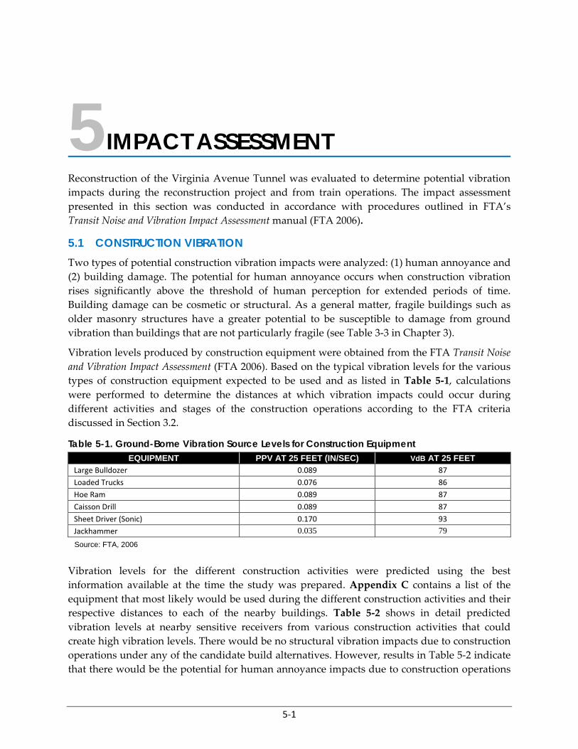
Vibration levels produced by construction equipment were obtained from the FTA Transit Noise and Vibration Impact Assessment (FTA 2006). Based on the typical vibration levels for the various types of construction equipment expected to be used and as listed in Table 5-1, calculations were performed to determine the distances at which vibration impacts could occur during different activities and stages of the construction operations according to the FTA criteria discussed in Section 3.2.
Table 5-1. Ground-Borne Vibration Source Levels for Construction Equipment EQUIPMENT PPV AT 25 FEET (IN/SEC) VdB AT 25 FEET
Large Bulldozer 0.089 87
Loaded Trucks 0.076 86 Hoe Ram 0.089 87
Caisson Drill 0.089 87
Sheet Driver (Sonic) 0.170 93
Jackhammer 0.035 79 Source: FTA, 2006
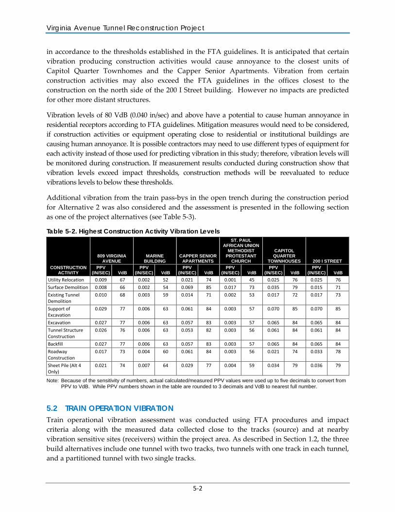
Vibration levels for the different construction activities were predicted using the best information available at the time the study was prepared. Appendix C contains a list of the equipment that most likely would be used during the different construction activities and their respective distances to each of the nearby buildings. Table 5-2 shows in detail predicted vibration levels at nearby sensitive receivers from various construction activities that could create high vibration levels. There would be no structural vibration impacts due to construction operations under any of the candidate build alternatives. However, results in Table 5-2 indicate that there would be the potential for human annoyance impacts due to construction operations
Virginia Avenue Tunnel Reconstruction Project
5-2
in accordance to the thresholds established in the FTA guidelines. It is anticipated that certain vibration producing construction activities would cause annoyance to the closest units of Capitol Quarter Townhomes and the Capper Senior Apartments. Vibration from certain construction activities may also exceed the FTA guidelines in the offices closest to the construction on the north side of the 200 I Street building. However no impacts are predicted for other more distant structures.
Vibration levels of 80 VdB (0.040 in/sec) and above have a potential to cause human annoyance in residential receptors according to FTA guidelines. Mitigation measures would need to be considered, if construction activities or equipment operating close to residential or institutional buildings are causing human annoyance. It is possible contractors may need to use different types of equipment for each activity instead of those used for predicting vibration in this study; therefore, vibration levels will be monitored during construction. If measurement results conducted during construction show that vibration levels exceed impact thresholds, construction methods will be reevaluated to reduce vibrations levels to below these thresholds.
Additional vibration from the train pass-bys in the open trench during the construction period for Alternative 2 was also considered and the assessment is presented in the following section as one of the project alternatives (see Table 5-3).
Table 5-2. Highest Construction Activity Vibration Levels
CONSTRUCTION ACTIVITY
809 VIRGINIA AVENUE
MARINE BUILDING
CAPPER SENIOR APARTMENTS
ST. PAUL AFRICAN UNION
METHODIST PROTESTANT
CHURCH
CAPITOL QUARTER
TOWNHOUSES 200 I STREET
PPV (IN/SEC) VdB
PPV (IN/SEC) VdB
PPV (IN/SEC) VdB
PPV (IN/SEC) VdB
PPV (IN/SEC) VdB
PPV (IN/SEC) VdB
Utility Relocation 0.009 67 0.002 52 0.021 74 0.001 45 0.025 76 0.025 76
Surface Demolition 0.008 66 0.002 54 0.069 85 0.017 73 0.035 79 0.015 71
Existing Tunnel Demolition
0.010 68 0.003 59 0.014 71 0.002 53 0.017 72 0.017 73
Support of Excavation
0.029 77 0.006 63 0.061 84 0.003 57 0.070 85 0.070 85
Excavation 0.027 77 0.006 63 0.057 83 0.003 57 0.065 84 0.065 84
Tunnel Structure Construction
0.026 76 0.006 63 0.053 82 0.003 56 0.061 84 0.061 84
Backfill 0.027 77 0.006 63 0.057 83 0.003 57 0.065 84 0.065 84
Roadway Construction
0.017 73 0.004 60 0.061 84 0.003 56 0.021 74 0.033 78
Sheet Pile (Alt 4 Only)
0.021 74 0.007 64 0.029 77 0.004 59 0.034 79 0.036 79
Note: Because of the sensitivity of numbers, actual calculated/measured PPV values were used up to five decimals to convert from PPV to VdB. While PPV numbers shown in the table are rounded to 3 decimals and VdB to nearest full number.
5.2 TRAIN OPERATION VIBRATION Train operational vibration assessment was conducted using FTA procedures and impact criteria along with the measured data collected close to the tracks (source) and at nearby vibration sensitive sites (receivers) within the project area. As described in Section 1.2, the three build alternatives include one tunnel with two tracks, two tunnels with one track in each tunnel, and a partitioned tunnel with two single tracks.
Vibration Analysis Report – Impact Assessment
5-3
Measured vibration levels from the existing train pass-bys at different locations were used to calculate soil vibration transferability characteristics, the highest vibration levels generated by the train, and tunnel structure vibration reduction effects. These values were then used to predict the future train pass-by vibrations impacts at various nearby sensitive locations.
Descriptions of the source of vibration from a freight train, the potential effects of the new tunnel on reducing vibration, and a summary of the parameters that were utilized to predict vibration levels associated with train pass-bys are presented in this section. Finally, the results of the impact assessment are provided, including the impact distances for existing and future ground-borne vibration from train pass-bys.
EFFECTS OF THE NEW TUNNEL The majority of track structure within the existing tunnel is sitting on dirt, while the proposed track structure within the new tunnel will be supported by a 3-foot thick reinforced concrete floor. A large mass such as the 3-foot thick concrete slab would reduce the vibrational energy generated by train pass-bys. Vibration levels at sensitive receptors would therefore be less from the new tunnel with its integral reinforced concrete floor in comparison to the existing tunnel with a natural earth floor. In addition the proposed use of a ballasted track section on top of the floor instead of directly attaching the tracks to the concrete floor slab, known as "direct fixation" has conservatively not been considered as well. The presence of ballast would serve to further reduce the vibrations reaching the soils below the floor slab. An exact vibration reduction effect for the proposed tunnel features cannot be determined from standard vibration modeling or from a review of published research data.
Despite the use of these techniques, future train vibration levels were predicted assuming a natural dirt floor that transmits more vibration energy into the surrounding soil in order to predict worst-case vibration levels. Vibration reduction effects of the new concrete walls were also not considered in the calculation; therefore, it can be expected that actual vibration levels would be substantially less than those estimated herein at receiver locations.
Is summary, as the tunnel adjustment factors (described further below) were determined from the measurements collected as part of this study, they would be lower than what is expected from measurements associated with the new tunnel.
ASSUMPTIONS AND ADJUSTMENTS TO VIBRATION PARAMETERS The following are list of assumptions that were made in order to calculate vibration levels from the Virginia Avenue Tunnel:
• Train Speed: Train operation vibration is typically higher when trains are traveling at higher speeds. The strength of ground-borne vibration reduces or increases approximately as much as 20 times the logarithm of the speed ratio of existing speed and proposed speed. This means that doubling the train speed will increase vibration levels approximately 6 VdB. Existing measured peak vibration levels were for a train travelling at an average speed of 20 mph; however, trains in the proposed tunnel would be traveling at a maximum speed of 40 mph. Therefore, a speed adjustment factor of an additional 6 VdB was applied to predict the future train pass-by vibration levels.
Virginia Avenue Tunnel Reconstruction Project
5-4
• Building Category: In determining the potential vibration impact distance, the lower limit of 0.012 in/sec specified by FTA for fragile buildings was utilized regardless of the type and age of the building (see Table 3-3). This is a conservative approach and has a safety factor built in.
• Train Vibration Source: The measured vibration levels at the east portal (Sites 1, 2, 3, and 4), which are the closest sites to the tracks without a tunnel structure or other interferences were used as the train source for calculating impact distances for the existing/no build alternative, temporary trench route for Alternative 2, and the three candidate build alternatives.
• Highest Vibration Levels: The highest recorded vibration level was used as the train vibration source in calculating the temporary trench alternative and the three candidate build concepts to ensure that future impact distances were not under predicted. One high train pass-by measured vibration was eliminated because it was determined that some unknown non-train vibration source occurred concurrently with the train generated vibration.
• Soil Disturbance: Soil to the south of the existing tunnel will be disturbed (excavated and replaced) up to the shoring line adjacent to the new south wall of the proposed tunnel. The remaining soils south of the shoring line will remain undisturbed. Along much of the alignment the area that will be disturbed is small in comparison to the amount of soil between the source (track) and the receivers (buildings). Therefore, the soil vibration transferability characteristics are predicted to be the same as they would be under existing conditions.
• Number of Trains: Vibration impact predictions were prepared assuming two trains were traveling in the tunnel simultaneously. This approach yielded the highest possible vibration impact resulting from train operations.
• Vibration Propagation: When a train is moving through a tunnel the vibration waves propagate less effectively from the tunnel floor to the ground surface than vibration waves generated by a train operating at grade (where vibration waves travel more effectively along the ground surface).
The following are list of assumptions that were made in order to calculate vibration levels from the proposed build alternatives for the reconstructed Virginia Avenue Tunnel:
• Proposed Track Alignment: An adjustment was applied to the measured vibration levels to account for a turnout near the east tunnel portal. This turnout will be eliminated once the new tunnel is constructed. Therefore, as per FTA guidelines, measured existing vibration levels that are used for calculating future vibration levels were reduced by 5 VdB with the removal of the discontinuity in the track represented by the turnout. This adjustment is needed to determine the vibration force generated by train pass-bys without the discontinuity which is then utilized for calculating the vibration effects from the trains in the new tunnel.
• Soil Factor: The calculated soil factor (see Section 4.2) was used as a parameter to adjust the rate that the vibration wave would decline in strength as it propagates away from the train.
Vibration Analysis Report – Impact Assessment
5-5
• Tunnel Adjustment Factor: Using the train force strength measured near the tracks at Sites 1, 2, 3, and 4 and the calculated soil factor, vibration levels were calculated at the other measurement locations. All of the calculated levels were higher than the measured level. The differences between the calculated and measured levels can be attributed to the tunnel’s vibration reduction characteristic. Tables B-2 and B-3 in Appendix B summarize the measured (with tunnel) and calculated (without tunnel) vibration levels for ten of the train pass-bys that were recorded in May 2012 and December 2013. Measurements from ten train pass-bys are sufficient for calculating a reliable tunnel adjustment factor. An averaged tunnel adjustment factor of 0.021 in/sec was derived from an analysis of both sets of data. This adjustment is for the existing tunnel and will be higher for the future tunnel due to the proposed integral reinforced concrete foundation which would provide a higher vibration reduction effect.
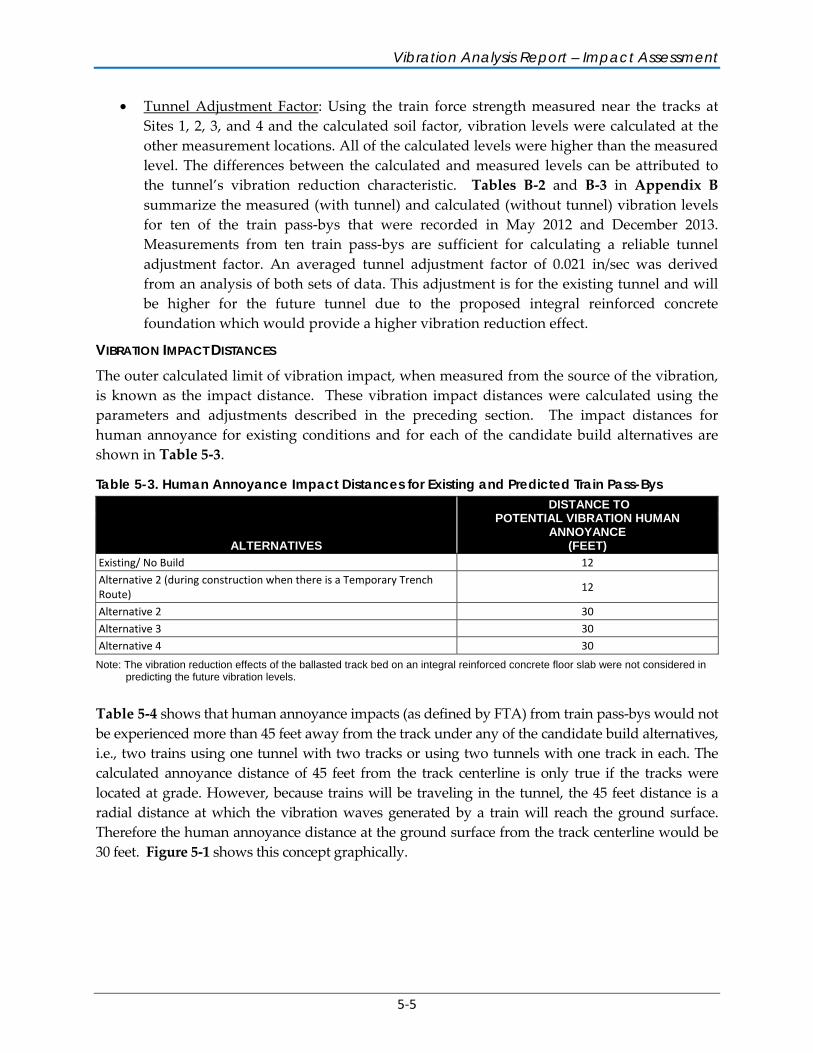
VIBRATION IMPACT DISTANCES The outer calculated limit of vibration impact, when measured from the source of the vibration, is known as the impact distance. These vibration impact distances were calculated using the parameters and adjustments described in the preceding section. The impact distances for human annoyance for existing conditions and for each of the candidate build alternatives are shown in Table 5-3.
Table 5-3. Human Annoyance Impact Distances for Existing and Predicted Train Pass-Bys
ALTERNATIVES
DISTANCE TO POTENTIAL VIBRATION HUMAN
ANNOYANCE (FEET)
Existing/ No Build 12
Alternative 2 (during construction when there is a Temporary Trench Route)
12
Alternative 2 30
Alternative 3 30 Alternative 4 30
Note: The vibration reduction effects of the ballasted track bed on an integral reinforced concrete floor slab were not considered in predicting the future vibration levels.
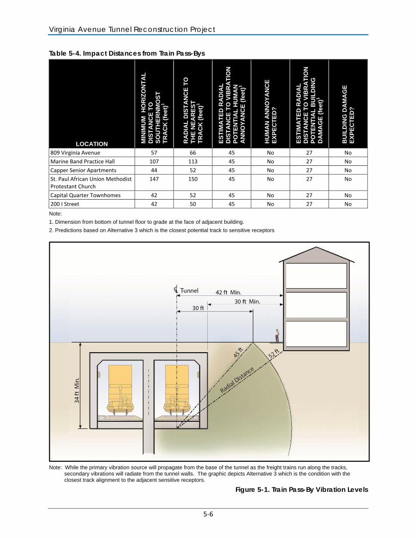
Table 5-4 shows that human annoyance impacts (as defined by FTA) from train pass-bys would not be experienced more than 45 feet away from the track under any of the candidate build alternatives, i.e., two trains using one tunnel with two tracks or using two tunnels with one track in each. The calculated annoyance distance of 45 feet from the track centerline is only true if the tracks were located at grade. However, because trains will be traveling in the tunnel, the 45 feet distance is a radial distance at which the vibration waves generated by a train will reach the ground surface. Therefore the human annoyance distance at the ground surface from the track centerline would be 30 feet. Figure 5-1 shows this concept graphically.
Virginia Avenue Tunnel Reconstruction Project
5-6
Table 5-4. Impact Distances from Train Pass-Bys
LOCATION MIN
IMU
M
HO
RIZ
ON
TA
L
DIS
TA
NC
E T
O
SO
UT
HE
RN
MO
ST
T
RA
CK
(fe
et)1
RA
DIA
L D
IST
AN
CE
TO
T
HE
NE
AR
ES
T
TR
AC
K (
feet
)1
ES
TIM
AT
ED
RA
DIA
L
DIS
TA
NC
E T
O V
IBR
AT
ION
P
OT
EN
TIA
L H
UM
AN
A
NN
OY
AN
CE
(fe
et)1
HU
MA
N A
NN
OY
AN
CE
E
XP
EC
TE
D?
ES
TIM
AT
ED
RA
DIA
L
DIS
TA
NC
E T
O V
IBR
AT
ION
P
OT
EN
TIA
L B
UIL
DIN
G
DA
MA
GE
(fe
et)
1
BU
ILD
ING
DA
MA
GE
E
XP
EC
TE
D?
809 Virginia Avenue 57 66 45 No 27 No
Marine Band Practice Hall 107 113 45 No 27 No
Capper Senior Apartments 44 52 45 No 27 No St. Paul African Union Methodist Protestant Church
147 150 45 No 27 No
Capital Quarter Townhomes 42 52 45 No 27 No
200 I Street 42 50 45 No 27 No
Note:
1. Dimension from bottom of tunnel floor to grade at the face of adjacent building.
2. Predictions based on Alternative 3 which is the closest potential track to sensitive receptors
Note: While the primary vibration source will propagate from the base of the tunnel as the freight trains run along the tracks,
secondary vibrations will radiate from the tunnel walls. The graphic depicts Alternative 3 which is the condition with the closest track alignment to the adjacent sensitive receptors.
Figure 5-1. Train Pass-By Vibration Levels
Vibration Analysis Report – Impact Assessment
5-7
Figures 2 through 4 in Appendix A show the 30-foot human annoyance impact line from two trains operating in the tunnel at the same time. As there are no residential buildings located between the impact line and the southern track of Alternative 3 (the closest potential track to sensitive receptors), there would be no predicted vibration impact from future train operations.
Table 5-5 and Table 5-6 provide a summary of the predicted level of ground borne vibration from construction and train operations, respectively, at each of the of the identified sensitive receptors along the tunnel alignment. The locations of all monitoring and prediction sites are shown in Appendix A – Figure 1. Note that some monitoring sites were selected to determine soil transferability characteristics and were not used for prediction sites (due to absence of receptors). For prediction purposes the offset distance, calculated PPV and VdB at the receptors and the controlling construction activity for Alternative 3 alignment was used as this represents the condition with the closest track alignment to the sensitive receptors. Further it should be noted that the estimated vibration levels shown on the tables do not consider the vibration reduction effect of the integral reinforced concrete floor, which would reduce the reported values for the peak estimated vibration levels shown in the tables.
Table 5-4 also shows that any building located 27 feet or more from the track centerline would not experience significant operational vibration impacts. As the tracks will be located a minimum of 34 feet underground with propagation paths (radial distances) of 52 to 150 feet for the receptor facilities along the corridor, no building damage is anticipated.
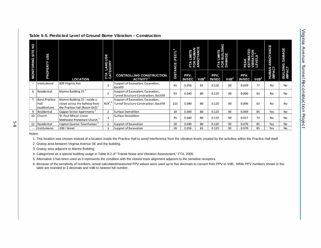
Virginia A
venue Tunnel Reconstruction Project
5-8
Table 5-5. Predicted Level of Ground Borne Vibration – Construction
Notes:
1. This location was chosen instead of a location inside the Practice Hall to avoid interference from the vibration levels created by the activities within the Practice Hall itself.
2. Grassy area between Virginia Avenue SE and the building.
3. Grassy area adjacent to Marine Building.
4. Categorized as a special building usage in Table 8-2 of “Transit Noise and Vibration Assessment,” FTA, 2006.
5. Alternative 3 has been used as it represents the condition with the closest track alignment adjacent to the sensitive receptors.
6. Because of the sensitivity of numbers, actual calculated/measured PPV values were used up to five decimals to convert from PPV to VdB. While PPV numbers shown in the table are rounded to 3 decimals and VdB to nearest full number.
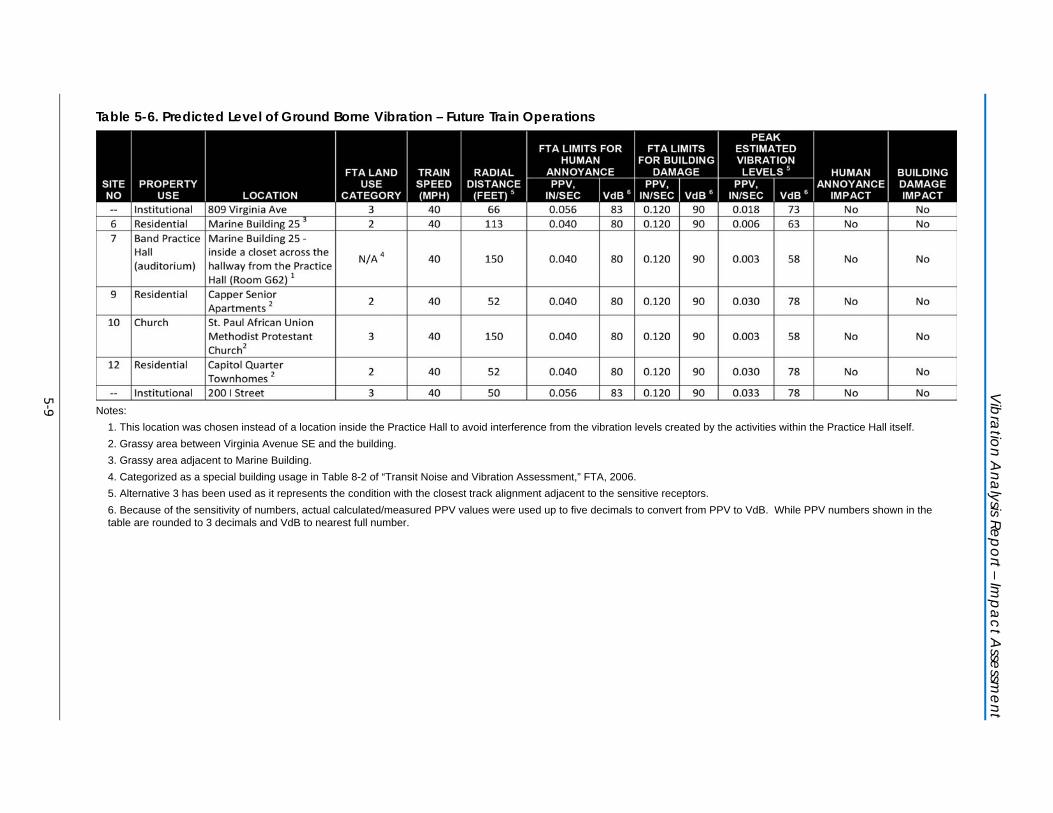
Vibration A
nalysis Report – Impact A
ssessment
5-9
Table 5-6. Predicted Level of Ground Borne Vibration – Future Train Operations
Notes:
1. This location was chosen instead of a location inside the Practice Hall to avoid interference from the vibration levels created by the activities within the Practice Hall itself.
2. Grassy area between Virginia Avenue SE and the building.
3. Grassy area adjacent to Marine Building.
4. Categorized as a special building usage in Table 8-2 of “Transit Noise and Vibration Assessment,” FTA, 2006.
5. Alternative 3 has been used as it represents the condition with the closest track alignment adjacent to the sensitive receptors.
6. Because of the sensitivity of numbers, actual calculated/measured PPV values were used up to five decimals to convert from PPV to VdB. While PPV numbers shown in the table are rounded to 3 decimals and VdB to nearest full number.

6-1
6 MITIGATION
This section discusses potential mitigation measures that can be implemented to reduce or mitigate vibration impacts resulting from reconstruction of the Virginia Avenue Tunnel and future train operations.
6.1 CONSTRUCTION VIBRATION MITIGATION It is possible that certain construction activities could cause intermittent localized concern from vibrations in the project area. Processes such as earth moving with bulldozers, the use of vibratory compaction rollers, and demolition could cause some human annoyance impacts. There are cases where it may be necessary to use this type of equipment in close proximity to residential buildings.
A vibration monitoring and mitigation plan will be prepared by a qualified vibration engineer prior to the start of construction. The plan would include vibration monitoring procedures at predetermined vibration sensitive sites, updated calculations of predicted vibration levels at the receptors based on measurements at the source of the actual construction activities, and recommendations for mitigation measures if they are needed based on the calculations. The plan will be a living document throughout construction and will be updated and submitted to DDOT should there be any major changes in findings, proposed mitigations or to the planned construction activities.
The plan would identify buildings that are candidates for pre- and post-construction surveys if they are close enough to a construction vibration source that may cause vibration impacts. The surveys would document the pre-construction condition of the structures in detail and final condition post construction. Findings if any, of damage as documented by the surveys would be addressed via the claims process which is described in the Environmental Impact Statement. Surveys would be conducted only with the permission of the owners of buildings.
The vibration monitoring and mitigation plan would also include, but not be limited to, the following items:
• The name and qualifications of the vibration specialist(s), who must have a Bachelor of Science or higher degree from a qualified program in engineering or physics offered by an accredited university or college, and at least 10 years of experience in vibration control engineering and vibration analysis. In addition to the basic requirements, vibration specialist must demonstrate substantial and responsible experience in conducting vibration measurements, calculating vibration propagation, as well as designing and overseeing the implementation of vibration abatement measures.
Virginia Avenue Tunnel Reconstruction Project
6-2
• The location of seismograph(s) placements on the existing and temporary tunnel, as well as nearby buildings, as directed by the vibration monitoring specialist.
• The scheduled start dates and length of construction operations that require vibration monitoring. There would be separate time intervals for each construction operation.
• The location of any sewer or water line in proximity to construction operations.
• Specifications of the seismograph including: the manufacturer’s name, model number, and documentation of factory calibration performed within the preceding 12 months. The seismograph will be capable of measuring peak particle velocity (PPV) data in three mutually perpendicular directions.
• Appropriate detailed procedures for placing and operating the seismograph.
• The procedure for tracking PPV throughout construction operations (e.g., sonic piling and drilling operations).
• A record of the time of day when each monitored construction activity took place.
The following are procedures that can be used to minimize the potential for human annoyance from construction vibration:
• Conduct vibration monitoring during vibration-intensive activities.
• Properly maintain all motorized equipment in a state of good repair to limit wear-induced vibration.
• Where feasible, avoid the use of impact type pile driving near residences; instead use drilled piles or the use of a sonic or vibratory pile driver, which cause lower vibration levels (where the geological conditions permit their use).
• When there is a possibility of human annoyance from construction activities, such as the operation of vibratory rollers, absent urgent and unexpected circumstances, conduct such activity only during weekday daytime hours when the ambient background noise and vibration is higher and many residents are away from their homes at work.
• Develop a phasing plan so that high vibration generating activities do not occur within the same time period is close proximity to each other, to the maximum extent practicable.
• Avoid routing heavily-loaded trucks through densely concentrated residential areas, when ever reasonably possible within the approved maintenance of traffic plans.
• Where feasible, use demolition methods that do not involve use of high impact tooling such as hoe rams and use crushing style attachments instead.
• Avoid the use of large vibratory rollers and packers near sensitive areas, when possible and use smaller equipment with smaller lifts.
A combination of the noted mitigation techniques for equipment vibration control as well as administrative measures, when properly implemented, can be selected to achieve the most effective means to minimize the effects of construction activities. Application of the noted
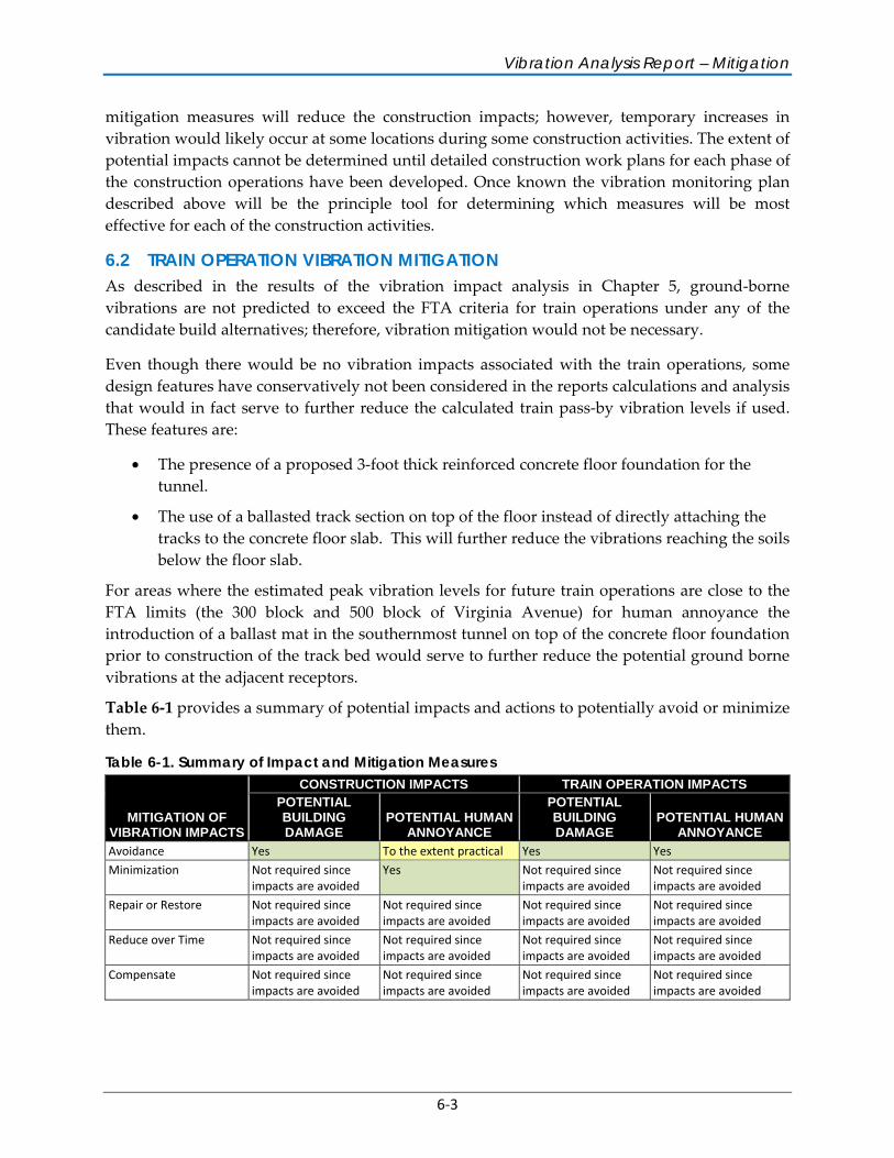
Vibration Analysis Report – Mitigation
6-3
mitigation measures will reduce the construction impacts; however, temporary increases in vibration would likely occur at some locations during some construction activities. The extent of potential impacts cannot be determined until detailed construction work plans for each phase of the construction operations have been developed. Once known the vibration monitoring plan described above will be the principle tool for determining which measures will be most effective for each of the construction activities.
6.2 TRAIN OPERATION VIBRATION MITIGATION As described in the results of the vibration impact analysis in Chapter 5, ground-borne vibrations are not predicted to exceed the FTA criteria for train operations under any of the candidate build alternatives; therefore, vibration mitigation would not be necessary.
Even though there would be no vibration impacts associated with the train operations, some design features have conservatively not been considered in the reports calculations and analysis that would in fact serve to further reduce the calculated train pass-by vibration levels if used. These features are:
• The presence of a proposed 3-foot thick reinforced concrete floor foundation for the tunnel.
• The use of a ballasted track section on top of the floor instead of directly attaching the tracks to the concrete floor slab. This will further reduce the vibrations reaching the soils below the floor slab.
For areas where the estimated peak vibration levels for future train operations are close to the FTA limits (the 300 block and 500 block of Virginia Avenue) for human annoyance the introduction of a ballast mat in the southernmost tunnel on top of the concrete floor foundation prior to construction of the track bed would serve to further reduce the potential ground borne vibrations at the adjacent receptors.
Table 6-1 provides a summary of potential impacts and actions to potentially avoid or minimize them.
Table 6-1. Summary of Impact and Mitigation Measures
MITIGATION OF VIBRATION IMPACTS
CONSTRUCTION IMPACTS TRAIN OPERATION IMPACTSPOTENTIAL BUILDING DAMAGE
POTENTIAL HUMAN ANNOYANCE
POTENTIAL BUILDING DAMAGE
POTENTIAL HUMAN ANNOYANCE
Avoidance Yes To the extent practical Yes Yes
Minimization Not required since impacts are avoided
Yes Not required since impacts are avoided
Not required since impacts are avoided
Repair or Restore Not required since impacts are avoided
Not required since impacts are avoided
Not required since impacts are avoided
Not required since impacts are avoided
Reduce over Time Not required since impacts are avoided
Not required since impacts are avoided
Not required since impacts are avoided
Not required since impacts are avoided
Compensate Not required since impacts are avoided
Not required since impacts are avoided
Not required since impacts are avoided
Not required since impacts are avoided

A-1
A VIBRATION MEASUREMENT SITES

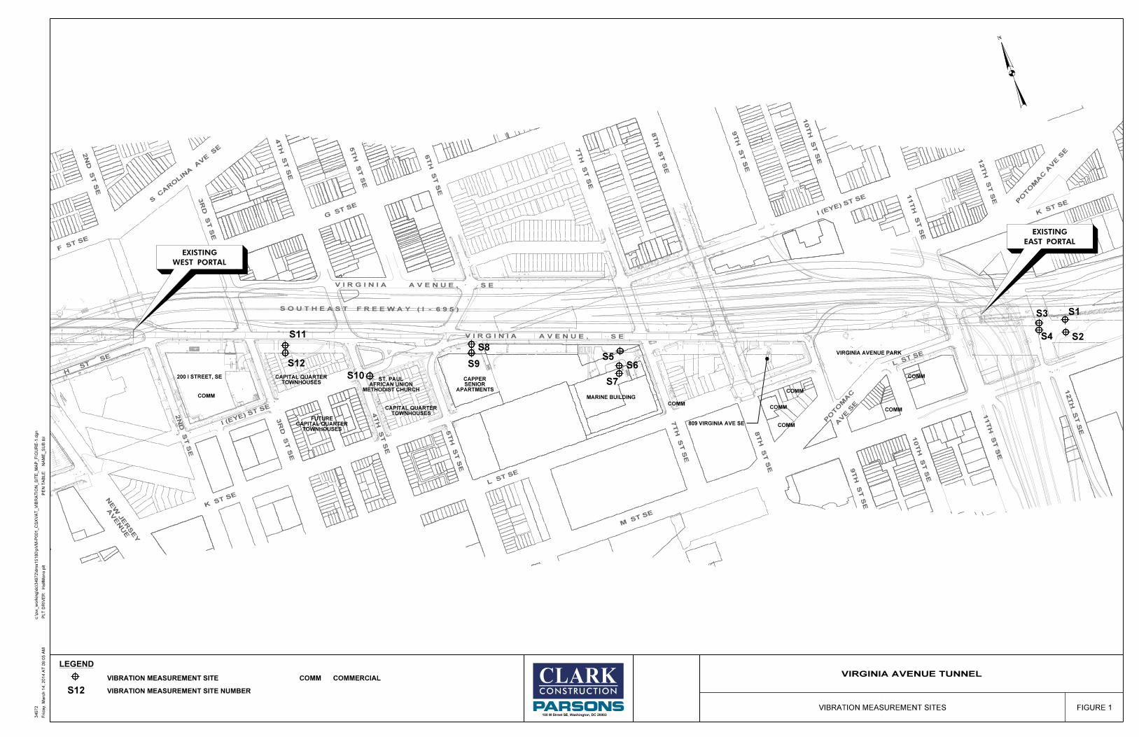
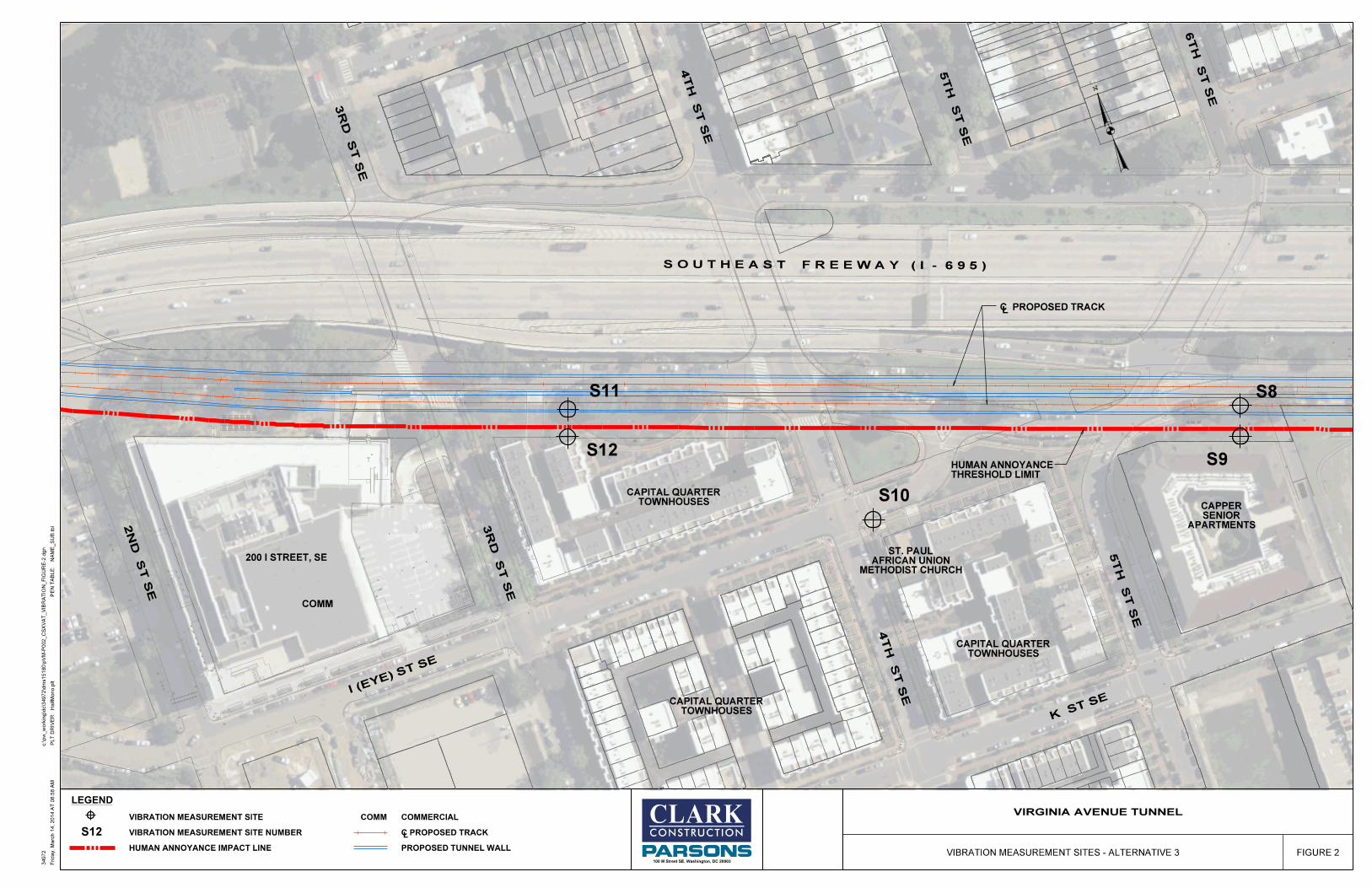
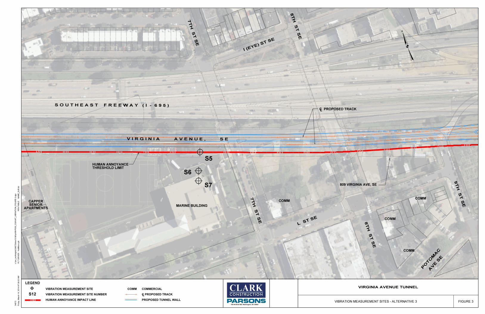
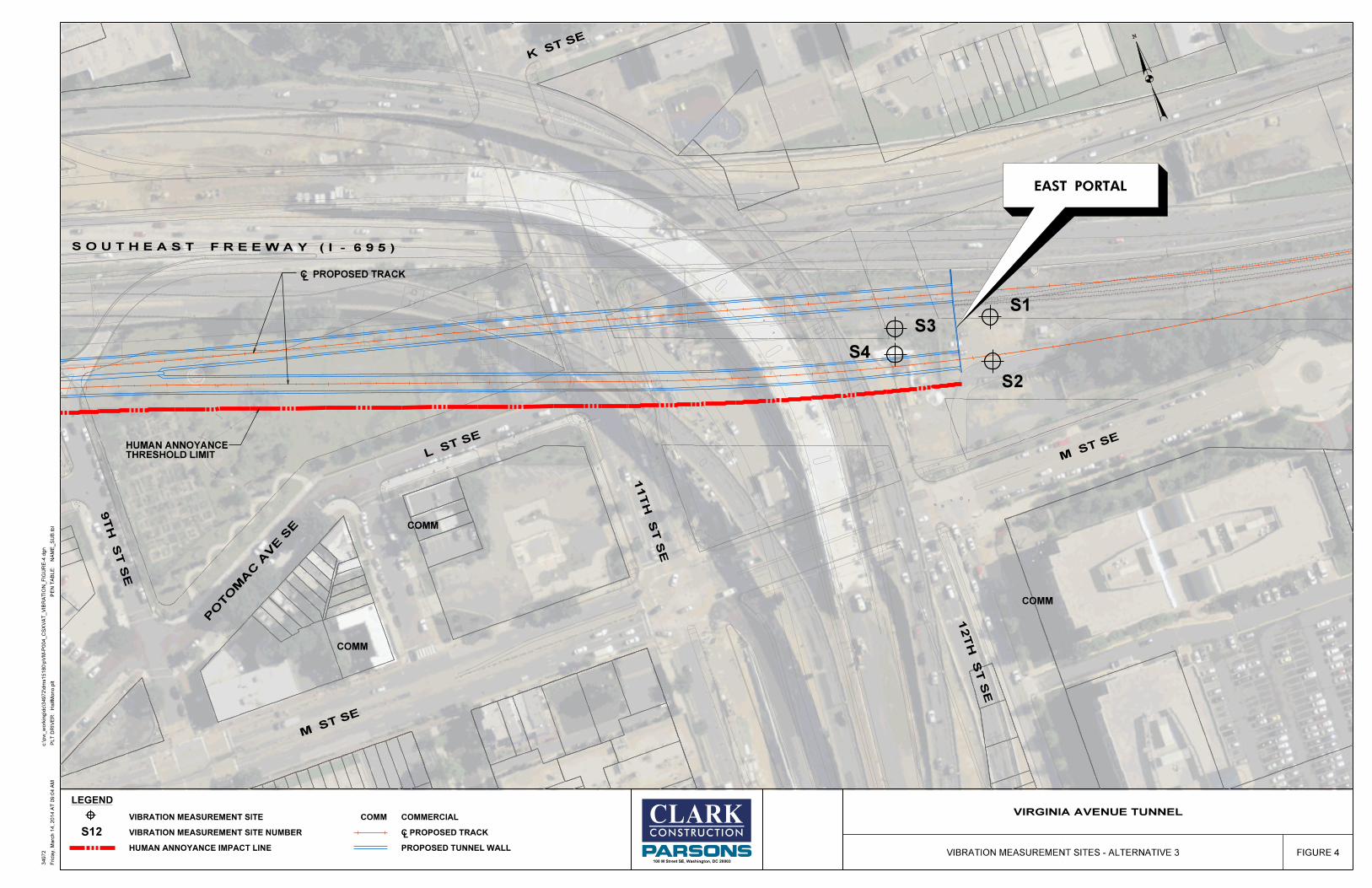
B-1
B SOIL VIBRATION TRANSFERABILITY AND REDUCTION DATA
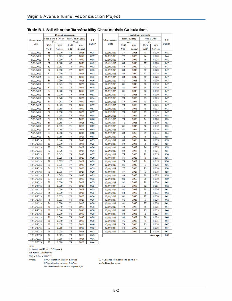
Virginia Avenue Tunnel Reconstruction Project
B-2
Table B-1. Soil Vibration Transferability Characteristic Calculations
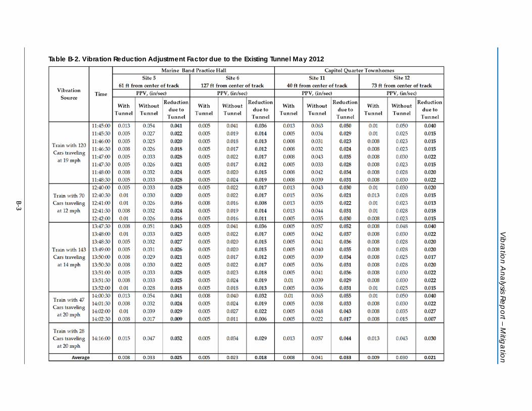
Vibration A
nalysis Report – Mitigation
B-3
Table B-2. Vibration Reduction Adjustment Factor due to the Existing Tunnel May 2012
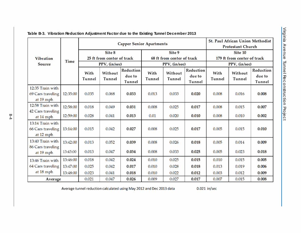
Virginia A
venue Tunnel Reconstruction Project
B-4
Table B-3. Vibration Reduction Adjustment Factor due to the Existing Tunnel December 2013
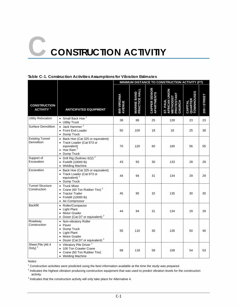
C-1
C CONSTRUCTION ACTIVITIY
Table C-1. Construction Activities Assumptions for Vibration Estimates
CONSTRUCTION ACTIVITY 1 ANTICIPATED EQUIPMENT
MINIMUM DISTANCE TO CONSTRUCTION ACTIVITY (FT)
809
VIR
GIN
IA
AV
EN
UE
MA
RIN
E B
AN
D
PR
AC
TIC
E H
AL
L
CA
PP
ER
SE
NIO
R
AP
AR
TM
EN
TS
ST
. PA
UL
A
FR
ICA
N U
NIO
N
ME
TH
OD
IST
P
RO
TE
ST
AN
T
CH
UR
CH
CA
PIT
AL
Q
UA
RT
ER
T
OW
NH
OU
SE
S
200
I ST
RE
ET
Utility Relocation • Small Back Hoe 2 • Utility Truck
38 88 25 128 23 23
Surface Demolition • Jack Hammer 2 • Front End Loader • Dump Truck
50 100 18 18 25 38
Existing Tunnel Demolition
• Back Hoe (Cat 325 or equivalent) • Track Loader (Cat 973 or
equivalent) • Hoe Ram 2 • Dump Truck
70 120 60 160 56 55
Support of Excavation
• Drill Rig (Soilmec 622) 2 • Forklift (10000 lb) • Welding Machine
43 93 30 133 28 28
Excavation • Back Hoe (Cat 325 or equivalent) • Track Loader (Cat 973 or
equivalent) 2 • Dump Truck
44 94 31 134 29 29
Tunnel Structure Construction
• Truck Mixer • Crane (60 Ton Rubber Tire) 2 • Tractor Trailer • Forklift (10000 lb) • Air Compressor
45 95 32 135 30 30
Backfill • Roller/Compactor • Light Plant • Motor Grader • Dozer (Cat D7 or equivalent) 2
44 94 31 134 29 29
Roadway Construction
• Non-vibratory Roller • Paver • Dump Truck • Light Plant • Motor Grader • Dozer (Cat D7 or equivalent) 2
55 110 30 135 50 40
Sheet Pile (Alt 4 Only) 3
• Vibratory Pile Driver 2 • 100 Ton Crawler Crane • Crane (60 Ton Rubber Tire) • Welding Machine
68 118 58 158 54 53
Notes: 1 Construction activities were predicted using the best information available at the time the study was prepared. 2 Indicates the highest vibration producing construction equipment that was used to predict vibration levels for the construction
activity. 3 Indicates that the construction activity will only take place for Alternative 4.


CLARK/PARSONS, JOINT VENTURE100 M Street SE, Suite 1200
Washington, DC 20003Phone: 202-775-3300 • Fax: 202-775-3420