appendix g wstp tag naming standard · pdf fileappendix g wstp tag naming standard rev00 ....
TRANSCRIPT

APPENDIX G WSTP TAG NAMING STANDARD REV00

Tag Naming Standard
Revision: 00 Page 3 of 33
Document Code: 612620-0014-40ER-0001
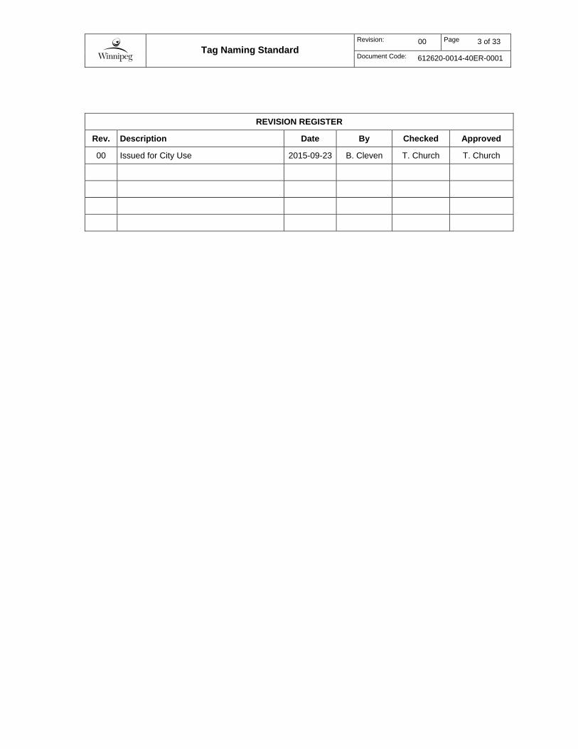
REVISION REGISTER
Rev. Description Date By Checked Approved
00 Issued for City Use 2015-09-23 B. Cleven T. Church T. Church

Tag Naming Standard
Revision: 00 Page 4 of 33
Document Code: 612620-0014-40ER-0001
This page is intentionally blank.
Tag Naming Standard
Revision: 00 Page 5 of 33
Document Code: 612620-0014-40ER-0001
TABLE OF CONTENTS
1 Introduction ................................................................................................... 7 1.1 Scope of the Standard .................................................................................................. 7 1.2 Application .................................................................................................................... 7 1.3 Definitions ..................................................................................................................... 7 1.4 Notes on Naming Conventions ..................................................................................... 8 1.5 References ................................................................................................................... 9
2 Basic Rules .................................................................................................. 10 2.1 General ....................................................................................................................... 10 2.2 Format ........................................................................................................................ 10 2.3 Common Abbreviations .............................................................................................. 11 2.4 Concatenation ............................................................................................................ 11
3 Classes......................................................................................................... 12
4 PLC Tags ...................................................................................................... 13 4.1 I/O Tag Format ........................................................................................................... 13
4.1.1 I/O Signal Conditioning .................................................................................. 13 4.2 Control System Functions .......................................................................................... 13
4.2.1 Control System Function Naming .................................................................. 13 4.2.2 Alarm Tags .................................................................................................... 15 4.2.3 Alarm Limit Tags ............................................................................................ 16 4.2.4 Control Loop Variables .................................................................................. 16
4.3 Internal Variables ........................................................................................................ 17 4.4 Global Variables ......................................................................................................... 18 4.5 Implementation Examples .......................................................................................... 19
4.5.1 Hardwired Motor Starter ................................................................................ 19 4.5.2 Networked Motor Starter ............................................................................... 20 4.5.3 Instrument-Valve Control Loop ...................................................................... 22
5 HMI Tags ...................................................................................................... 24 5.1 General ....................................................................................................................... 24 5.2 Tag Name Format ...................................................................................................... 24
5.2.1 HMI Tags associated with Derived Function Block Parameters ................... 24 5.2.2 HMI Tags associated with PLC Tags ............................................................ 24
5.3 Equipment.Item Format .............................................................................................. 25 5.4 Example ...................................................................................................................... 26
Appendix A ............................................................................................................. 27 A.1 Field Equipment Identification .................................................................................... 28
A.1.1 Instrument Identifier Format .......................................................................... 28 A.1.2 Mechanical, Electrical and Automation Equipment Identifier Format ............ 29 A.1.3 Subcomponent Identifier Format ................................................................... 29 A.1.4 Facility Code .................................................................................................. 30
Appendix B ............................................................................................................. 31 B.1 Standard Abbreviations .............................................................................................. 32
B.1.1 Additional References ................................................................................... 33

Tag Naming Standard
Revision: 00 Page 6 of 33
Document Code: 612620-0014-40ER-0001
LIST OF TABLES Table 1 – Common Functional Designations 14 Table 2 – Common Control Loop Functional Designations 17 Table 3 – Standard Abbreviations 32

Tag Naming Standard
Revision: 00 Page 7 of 33
Document Code: 612620-0014-40ER-0001
1 INTRODUCTION
This Water and Waste Department Sewage Treatment Plant Tag Naming Standard is to be referenced for consistent naming of software tags within the PLC (I/O, variables, and control system functions) and HMI. This standard is an extension of the Identification Standard, document 510276-0000-40ER-0002, and it follows the same rules. Where there are discrepancies between these two standards, this standard shall take precedence for PLC and HMI programming.
1.1 Scope of the Standard
This identification standard, document 510276-0000-40ER-0002, applies to all PLC, HMI, and SCADA systems in City-owned sewage treatment plants, which includes the following facilities:
1. North End Sewage Treatment Plant (NEWPCC)
2. South End Sewage Treatment Plant (SEWPCC)
3. West End Sewage Treatment Plant (WEWPCC)
These design requirements will also be applied to the collection system where relevant and useful.
1.2 Application
This Standard is meant as a guideline for control system developers to provide consistent tag naming across all City sewage treatment plants. Although every conceivable tag naming scenario cannot be covered in this document, developers are expected to follow the general intent and guidelines provided herein.
Existing facilities do not necessarily comply with this standard. The expectations regarding application of this standard to existing facilities must be decided on a case-by-case basis with consideration of the future arrangement of the facility, however general guidelines for application are presented as follows:
1. All new custom process control system applications developed for the City shall follow this standard. It is not expected that pre-developed PLC or HMI applications from packaged equipment vendors follow these rules, but where pre-developed PLC or HMI applications from a vendor allows customizable options by the vendor before delivery, the intent of this standard should be followed as reasonably practicable.
2. All new facilities must comply with this standard.
3. All upgrades to a facility that require the installation of a PLC or HMI must comply with this standard.
4. All minor upgrades to an existing control system should utilize this standard as far as practicable, however in some cases compromise with the existing control system identification practice may be required. For example, addition of new tags to the Bailey Infi90 control system.
1.3 Definitions
Class A template definition of the PLC and HMI logic, variables, and graphic symbols associated with a particular type of equipment. Within the Schneider Electric software, this is typically implemented as a Derived Function Block in the Unity Pro PLC programming software and a Genie or Super-Genie in the Vijeo Citect HMI software.

Tag Naming Standard
Revision: 00 Page 8 of 33
Document Code: 612620-0014-40ER-0001
Control System Function Functions within a PLC program related to the control and monitoring
of equipment/instruments. Control System Functions shown on the P&IDs are typically in the form of a square-enclosed circle. These can be implemented either as an instance of a Derived Function Block or a grouping of Elementary Function Blocks.
Derived Function Block A user-defined PLC function block containing custom logic and that has been added to the function block library. These are defined once and are instantiated for use in the PLC program.
Elementary Function Block Predefined PLC function blocks in the function block library that typically cannot be modified by users.
Equipment.Item Within the Vijeo Citect HMI software, this is a field for a Variable Tag. It is generated within the software by combining the Equipment and Item Name fields that are defined by the developer. When this term is used within this document it will be italicized.
FDT/DTM Field Device Tool / Device Type Manger. A tool for configuring the communication interface between field devices and the PLC system. The Schneider Electric Unity Pro PLC programming software incorporates an FDT frame for loading device DTMs from the device manufacturers.
Instance A specific realization of a class. Within the Schneider Unity Pro software, each time a Derived Function Block is used within a PLC program it is an instance of a class.
Parameter An attribute (input, output, or internal variable) of a class or function block. This portion of the tag provides a name of the signal.
Tag A variable utilized within a PLC or HMI program. ‘Tag’ is synonymous with ‘Variable’.
Tag Name The actual identifier assigned to a specific tag. When this term is used within this document it will be italicized.
Variable Data used by a PLC or HMI that is stored at a unique memory address. ‘Variable’ is synonymous with ‘Tag’.
Variable Tag A term used in the Vijeo Citect HMI software that refers to an HMI tag that is linked to a PLC tag. It can be referenced within the HMI program by either the associated Tag Name or Equipment.Item. When this term is used within this document it will be italicized.
1.4 Notes on Naming Conventions
In the following sections, the naming convention for tags and classes are defined in tables. The following notes offer an explanation of the conventions utilized within the tables:
1. A number of letters in succession represents a parameter that must have the same number of characters as the number of letters. For example, NNN in Section 4.2.1.1 indicates three digits must be used for the equipment number.
2. A letter with a star indicates a variable number of characters. For example, X* in Section 4.2.1.1 could represent between two and four characters.

Tag Naming Standard
Revision: 00 Page 9 of 33
Document Code: 612620-0014-40ER-0001
1.5 References
The following City of Winnipeg standards may be referenced where applicable:
1. Water and Waste Department Identification Standard, document 510276-0000-40ER-0002,
2. Wastewater Treatment Electrical Design Guide, document 510276-0000-40ER-0002,
3. Wastewater Treatment Automation Design Guide, document 612620-0013-40ER-0001,
4. HMI Layout and Animation Plan, document 612620-0015-40ER-0001,
5. Historical Data Retention Standard, document 612620-0016-40ER-0001.
The following industry standards and guidelines may be referenced where applicable:
1. ANSI/ISA-5.1-2009, Instrument Symbols and Identification.
The following Schneider Electric help system documents may be referenced where applicable:
1. Unity Pro Help » Unity Pro Software » Languages Reference » Data Description » Syntax Rules for Type\Instance Names
2. Unity Pro Help » Unity Pro Software » Data Description » Data References » Data Naming Rules
3. Vijeo Citect Online Help – Tagging Process Variables, http://www.citect.schneider-electric.com/webhelp/vijeo2015/Content/Tagging_Process_Variables.html
4. Vijeo Citect Online Help – Tag Name Syntax, http://www.citect.schneider-electric.com/webhelp/vijeo2015/Content/Tag_name_syntax.html

Tag Naming Standard
Revision: 00 Page 10 of 33
Document Code: 612620-0014-40ER-0001
2 BASIC RULES
2.1 General
In general, all tags utilized within the Process Control System (PCS) should be named in a manner that is consistent with how they are shown on the P&IDs. PCS tag names will include the identifier of the equipment or control system function they are associated with (e.g. P-P217.Run).
The City of Winnipeg Identification Standard, document 510276-0000-40ER-0002, uses hyphens and periods as separation characters within identifiers (e.g. VFD-G101.Flt). For PLC variables, Schneider Electric’s Unity Pro software does not allow the use of hyphens in variable names and therefore hyphens must be replaced with underscores in PLC programs. Unity Pro only supports the use of periods in variable structures but not in regular variables. As such, it is required to replace periods with underscores for regular variables within PLC programs. For HMI variables, Schneider Electric’s Vijeo Citect software does not support hyphens or periods, but does support backslashes (“\”). Therefore all hyphens will be replaced with underscores, and periods will be replaced with backslashes. Note that Vijeo Citect does support periods in the Equipment.Item hierarchy, which is further discussed in Section 5.
Variables shall be based on positive logic, with the “1 State” or 100% being the active state or full range of the signal. Tag naming should reflect this philosophy. I/O signals may use negative or fail safe logic, but they will need to be conditioned (negated in the discrete case) before use.
2.2 Format
Classes, function blocks, parameters, and variables implemented in the PCS shall be named using the following characters:
Uppercase letters A through Z
Lowercase letters a through z
Numerals 0 through 9
Underscore “_”
Period “.” (for PLC variables only)
Backslash “\” (for HMI variables only)
All names shall start with a letter. Hyphens or spaces are not allowed in a name.
Periods are used in the PLC system as a separation character between a function block instance name and its parameters (eg. YC_P2041.CmdStart) and for tag structures. Periods are not used otherwise.
Periods are not permitted in HMI variable names and therefore backslashes are used in the HMI system as a separation character between a function block instance name and its parameters (eg. YC_P2041\CmdStart).
Where possible, use ISA 5.1 style identification as per Table 4.1 in ANSI/ISA-5.1-2009 for naming classes, function blocks, parameters, and variables (eg. “F” for flow, “P” for pressure, “C” for control, etc.). Where ISA 5.1 variables are used, they shall be capitalized. If ISA 5.1 variables are not suitable, English words, abbreviations, or acronyms may be used.
Where English words or abbreviations are used within a name, each will begin with an upper case letter and the remaining letters in lowercase. Additionally, acronyms are completely capitalized.

Tag Naming Standard
Revision: 00 Page 11 of 33
Document Code: 612620-0014-40ER-0001
Names shall be unique. Names differing only in the use of lowercase and uppercase letters are not permitted (e.g. FAL and Fal).
2.3 Standard Abbreviations and Acronyms
Abbreviations and acronyms may be used in the naming of objects where ISA 5.1 style identification is not suitable. Note that it is permitted to use ISA 5.1 style identification along with abbreviations and acronyms in the naming of an object. The purpose of using abbreviations and acronyms, rather than complete English words, is to minimize the length of object names.
Standardized abbreviations and acronyms used in the identification of classes, function blocks, parameters and variables are provided in Appendix B.
It may be required to add new standard abbreviations or acronyms, where the existing list does not cover a new application. In this instance, the proposed abbreviation or acronym is to be reviewed with the City, and if approved then it shall be added to the list in Appendix B.
If additional abbreviations are used, ensure that they are consistently applied throughout the entire PLC and HMI program.
2.4 Concatenation
When concatenating multiple words or abbreviations to form a name or a part of a name, no spaces or underscores shall be present between identifiers or abbreviations, with the following exceptions:
If a name or part of a name is formed by concatenating two strings and the first string ends with a number, an underscore (“_”) will be used to separate the two strings:
o E.g. “Eqmt1_Rdy” contains an underscore following “Eqmt1” because it ends with a number.
All letters in ISA 5.1 style identifiers and variables are capitalized, therefore they will be separated from succeeding identifiers or abbreviations with an underscore (“_”)
o E.g. “KQ_Rst” contains an underscore following the “KQ” variable because it ends with a capital letter.
o E.g. “F_Max” contains an underscore following the “F” variable because it ends with a capital letter.
All letters in acronyms are capitalized, therefore they will be separated from succeeding identifiers or abbreviations with an underscore (“_”)
o E.g. “HOA_Auto” contains an underscore following the “HOA” acronym because it ends with a capital letter.

Tag Naming Standard
Revision: 00 Page 12 of 33
Document Code: 612620-0014-40ER-0001
3 CLASSES
A class is a template that is used to create an object within the PCS. A typical class is a collection of PLC program logic together with HMI graphic objects. The PLC portion of a class is implemented in the Schneider Electric Unity Pro software using a Derived Function Block. The HMI portion of a class is implemented in Vijeo Citect using a Genie or Super-Genie that is linked to Equipment object(s) in Vijeo Citect.
A number of standard classes are currently in development for the City’s Sewage Treatment Program. Contact the City for the current status on the development of these classes, and to obtain copies of completed classes. Additional classes may be developed as required for common control system functions to allow for rapid system development.
New classes that are developed shall be named in a manner that gives a clear indication of the functionality contained in the class. All class names shall follow the basic rules indicated in Section 2. Where the class could be used for different types of equipment, it should be named generically enough so that the name fits all pieces of equipment (e.g. EqmtStatus as opposed to MotorStatus).
Not all PLC program logic is necessarily templated from a class. In some cases, program logic may be implemented using Elementary Function Blocks in the PLC program. However, all variables read by the HMI system should be read from a derived function block (class) within the PLC.

Tag Naming Standard
Revision: 00 Page 13 of 33
Document Code: 612620-0014-40ER-0001
4 PLC TAGS
4.1 I/O Tag Format
The tag naming standard for I/O signals is as per the City of Winnipeg Identification Standard, document 510276-0000-40ER-0002, Section 7.8.
The tag naming standard for fire alarm signals is as per the City of Winnipeg Identification Standard, document 510276-0000-40ER-0002, Section 6.7.
4.1.1 I/O Signal Conditioning
Input signals from physical I/O or a communication network require conditioning before being used in the PLC program. This is to ensure that all input signals remain constant throughout the program scan, and also allows for input channel re-assignment, signal inversion, and scaling if necessary. Input signal conditioning is performed in separate input signal conditioning routines. Likewise, output signals shall be mapped to the respective physical or network outputs in an output signal conditioning routine. While output signals do not always require conditioning, output channel reassignment may be required in the future, which would be performed in the output signal conditioning routine.
Signals directly associated with physical I/O or networked devices are called raw signals, and the tag name for all raw signals shall have an underscore appended to it.
The I/O conditioning logic may include a check on the quality of the signal. An error status will be set when there is a clear indication that the values are not being read or written properly, the wires are disconnected or shorted, or in the case of analog signals, the values are overrange or underrange (the possible checks depend on the I/O card and type of wiring). The tag indicating bad quality will be the conditioned I/O tag plus “_Err”.
Examples:
TSH_M6011_ Temperature switch raw input.
TSH_M6011 Temperature switch conditioned input.
TSH_M6011_Err Temperature switch input bad quality status.
Refer to the implementation examples in Section 4.5 for detailed I/O signal conditioning implementations for both physical I/O and networked devices.
4.2 Control System Functions
4.2.1 Control System Function Naming
4.2.1.1 Control System Functions for Devices
Control system functions shown on P&IDs or described in the Functional Requirements Specification (FRS) shall be given an ISA 5.1 style tag. These functions typically are directly related to the control and monitoring of a particular piece of equipment or instrument, and the Loop Number will be determined from the equipment or instrument Loop Number. The identifier of the Control System Function implemented in the PLC and HMI should match the identifier of the Control System Function shown on the P&ID.

Tag Naming Standard
Revision: 00 Page 14 of 33
Document Code: 612620-0014-40ER-0001
The identification format for control system functions for devices is as follows:
X* - P NNN T
Functional Designation
- Process Area
Equipment Number
Instrument Number
Loop Number
Where,
X* is the Functional Designation, which is typically composed of two to four uppercase letters based upon ISA 5.1. Common Functional Designations are shown below:
Table 1 – Common Functional Designations
Functional Designation Description
YC Controller for a major piece of equipment
XC Controller for a valve or damper with discrete states
YL Indicator for equipment with discrete states
PAL, LAL, etc. Alarms
LIC, FIC, etc. Controller of an analog variable
LI, FI, etc. Indicator of an analog variable
FK Control Station to allow HMI override
P is the Process Area. The process area code identifies the physical area or building in which the equipment is located. A single letter character from A to Z represents a process area as per Identification Standard, document 510276-0000-40ER-0002.
NNN is the Equipment Number of the associated equipment.
T is the Instrument Number of the associated instrument.
NNNT is the Loop Number of the associated equipment, composed of the Equipment Number together with the Instrument Number.
Examples:
YC-G1010 Controller for pump P-G101.
YL-B6510 Indicator for boiler BLR-B651. Note that there could be multiple signals being indicated.
FI-G2346 Flow indicator associated with flowmeter FIT-G2346.
LAH-R2100 Digital alarm/indicator to indicate high level alarm from high level switch LSH-R2100.
4.2.1.2 Control System Functions for Overall Control Schemes
Control system functions for overall control schemes provide higher level control for multiple pieces of equipment and shall be given an identifier similar to control system functions for devices.

Tag Naming Standard
Revision: 00 Page 15 of 33
Document Code: 612620-0014-40ER-0001
The first and second digits of the loop number should match the first and second digits of the associated equipment loop numbers. The fourth digit should be a “0”, however this may not always be possible as it may conflict with an existing loop number assigned to an instrument. If a loop number ending in “0” would result in a conflict, consider using a loop number that ends with “8” or “9” to reduce potential conflicts with other instrumentation. In more complex controllers, a new Loop Number should be chosen.
The PLC logic for an overall control scheme is not required to be encapsulated in a Derived Function Block, however, a separate subroutine (logic diagram) should generally be provided.
The identification format for overall control schemes is as follows:
X* - P NNNN _ F*
Functional Designation
- Process Area
Loop Number
_ Functional Description
Where,
X* is the Functional Designation, which is typically composed of two to four uppercase letters based upon ISA 5.1. Common Functional Designations are provided in Table 1 above.
P is the Process Area. The process area code identifies the physical area or building in which the overall control scheme is used. A single letter character from A to Z represents a process area as per Identification Standard, document 510276-0000-40ER-0002.
NNNN is the Loop Number, which is a four digit number assigned to the control scheme. Where the overall control scheme is associated with equipment, the first and second digits of the Loop Number should match that of the equipment numbers.
F* is a description of the functionality. This should adequately describe the function to allow for easy interpretation of its purpose.
Examples:
XC-R4100_MasterController Master controller for blowers B-R411, B-R412, B-R413, and B-R414.
YC-P2001_DestSelector Controller that determines which location sludge should be pumped to.
4.2.2 Alarm Tags
Identification of alarms that are generated directly from a discrete input will be as per Section 4.2.1.1.
Identification of alarms that are not generated directly from a discrete input will be as follows:
C* s A*
Control System Function
.
Alarm Designation
Where,
C* is the Control System Function tag, as defined in Section 4.2.1.
s is the Separation Character. If the Control System Function is an instance of a class, this will be a dot. If not, it will be an underscore.

Tag Naming Standard
Revision: 00 Page 16 of 33
Document Code: 612620-0014-40ER-0001
A* is the Alarm Designation, which uses ISA alarm designations where possible.
Where ISA alarm designations are not used, the Alarm Designation shall be composed of the letters “Alm” followed by a description of the alarm using abbreviations and acronyms where possible.
Examples:
XC-G6121.ZAO An Open Fail Alarm associated with valve XC-G6121.
YC-B6710.PAL Pressure Alarm for Low Seal Water from the YC-B6710 controller, which is associated with pump P-B671.
YC-S2160_AlmNoPumpsAvail No Sludge Pumps available to run. YC-S2160 is a control system function for an overall control scheme, not an instance of a class.
4.2.3 Alarm Limit Tags
Identification of analog limit values for the generation of alarms will be as follows:
C* s A* _ LMT
Control System Function
.
Alarm Designation
_ Limit Designation
Where,
C* is the Control System Function tag, as defined in Section 4.2.1.
s is the Separation Character. If the Control System Function is an instance of a class, this will be a dot. If not, it will be an underscore.
A* is the Alarm Designation, which uses ISA alarm designations where possible. Where ISA alarm designations are not used, the Alarm Designation shall be composed of the letters “Alm” followed by a description of the alarm using abbreviations and acronyms where possible.
LMT is the Limit Designation, which is composed of the letters “LMT”.
Example:
TI-G6031.AlmHiHi_LMT A High-High Temperature Alarm Limit setting for TI_G6031.
4.2.4 Control Loop Variables
Identification of control loop variables for PID control loops, will be as follows:
C* s F*
Control System Function
.
Control Loop Functional Designation
Where,
C* is the Control System Function name, as defined in Section 4.2.1.
s is the Separation Character. If the Control System Function is an instance of a class, this will be a dot. If not, it will be an underscore.

Tag Naming Standard
Revision: 00 Page 17 of 33
Document Code: 612620-0014-40ER-0001
F* is the Control Loop Functional Designation defined in the table below:
Table 2 – Common Control Loop Functional Designations
Functional Designation Description
PV Process Variable
CV Control Variable
Auto_SP Setpoint when in Auto Mode
Oper_SP Setpoint from Operator via HMI
Note that the above list is not exhaustive, and for other types of control loops (i.e. other than PID control), other functional designations may be required. Use ISA 5.1 style identification, and/or the standard abbreviations and acronyms found in Appendix B, for naming these control loop functional designations.
Examples:
FIC-S1501.PV The process variable (flow signal) for PID controller FIC-S1501 from flow meter FIT-S1501.
LIC-R4001.CV The control variable (output signal) from the PID controller LIC-R4001 associated with tank TK-R400.
TIC-R6021.Auto_SP The automatic mode setpoint for PID controller TIC-R6021.
4.3 Internal Variables
Identification of internal variables not associated with a specific piece of equipment or instrument loop, where the variable will be not used beyond the originating PLC, will be as follows:
C* s F*
Control System Function
.
Signal Description
Where,
C is the Control System Function name, formatted as per Section 2.2. Where the Control System Function name is associated with multiple pieces of equipment, a name is chosen that has some commonality with the identifiers of the equipment.
s is the Separation Character. If the Control System Function is an instance of a class, this will be a dot. If not, it will be an underscore.
F* is the Signal Description composed of abbreviations and acronyms where possible. This should adequately describe the signal to allow for easy interpretation.
Examples:
YC_S6001_State The state variable for the state controller controlling Wet Well ventilation.
YC_G1000_WeatherMode A discrete variable indicating Summer or Winter mode associated with the raw sewage pumps.

Tag Naming Standard
Revision: 00 Page 18 of 33
Document Code: 612620-0014-40ER-0001
4.4 Global Variables
In some cases it will be required to read a variable from another PLC. A variable that is read from another PLC shall be considered a global variable. The global variable in the destination PLC shall be identified as follows:
GBL P NNN _ T*
Global Designation
Process Area PLC Equipment Number
_ Originating Tag Name
Where,
GBL is the Global Designation, consisting of the letters “GBL”.
P is the Process Area of the originating PLC.
NNN is the Equipment Number of the originating PLC.
T* is the Originating Tag Name, which is the name of the tag that is being read from the remote PLC.
Examples:
GBL_R801_AIC_R1051.PV The process variable associated with PID controller AIC-R1051 originating from PLC-R801.
GBL_P801_FI_P1081 Flow signal from flow meter FIT-P1081 originating from PLC-P801.

Tag Naming Standard
Revision: 00 Page 19 of 33
Document Code: 612620-0014-40ER-0001
4.5 Implementation Examples
4.5.1 Hardwired Motor Starter
The P&ID example below shows scum recirculation pump P-P217 with control system function YC-P2170. As per the Identification Standard, document 510276-0000-40ER-0002, the inputs are P-P217.Run, P-P217.Rem, and P-P217.PSL, and the output is P-P217.CmdRun.
Figure 4-1 – Example P&ID for Hardwired Motor Starter
The raw PLC input tags before conditioning are:
P_P217_Run_ P_P217_Rem_ PSL_P2171_
Within the input conditioning routing, the raw PLC input tags are conditioned to the following tags:
P_P217_Run P_P217_Rem PSL_P2171

Tag Naming Standard
Revision: 00 Page 20 of 33
Document Code: 612620-0014-40ER-0001
The function instance YC-P2170 will reside in the pump subroutine and will have the above conditioned PLC tags mapped to the following input parameters (not all parameters are shown):
YC_P2170.Run YC_P2170.Rem YC_P2170.PSL
Some of the HMI commands that interface with the YC-P2170 function instance are:
YC_P2170.ManStart YC_P2170.ManStop YC_P2170.Rst
YC-P2170 will have the following class output and alarm parameters (not all parameters are shown):
YC_P2170.CmdRun YC_P2170.PAL YC_P2170.AlmRunFlt
Within the pump subroutine, the YC_P2170.CmdRun output will write to the following tag:
P_P217_CmdRun
Within the signal conditioning routine, the P_P217_CmdRun tag will write to the following raw PLC output tag:
P_P217_CmdRun_
4.5.2 Networked Motor Starter
The P&ID example below shows a fermenter recirculation pump P-D321 with control system function YC-D3210. The starter associated with this pump is a networked starter (eg. Schneider Electric TeSys T), and as such there will be a significant amount of data that can be read from the starter.
Figure 4-2 – Example P&ID for Networked Motor Starter

Tag Naming Standard
Revision: 00 Page 21 of 33
Document Code: 612620-0014-40ER-0001
The control system function YC-D3210 is implemented as an instance of a PumpBasic class, which is a class developed for the City of Winnipeg Sewage Treatment Program. Within the PLC, the PumpBasic derived function block (DFB) does not perform the actual data exchange with the networked motor starter. The PumpBasic DFB is linked to a TeSys DFB that was developed by Schneider Electric, which performs the data exchange. The identifier for the TeSys DFB instance should be the same as the control system function but with an underscore (“_”) appended to the identifier (eg. YC_D3210_).
The PumpBasic DFB would reside in the subroutine dedicated to overall control and functionality of the equipment. The TeSys DFB would reside in a signal conditioning routine since it maps the raw (unconditioned) networked I/O signals to conditioned PLC tags.
The input and output pins of the TeSys DFB connect to conditioned tags within the signal conditioning routine. Conditioned tags do not end with an underscore. These conditioned tags then connect to the input and output pins of the PumpBasic DFB in the equipment subroutine.
The following provides an example of linking some of the signals between the TeSys DFB and the PumpBasic DFB. Due to the quantity of signals associated with the TeSys DFB, not all signals are included in this example.
Within the signal conditioning subroutine, some of the signals obtained from the TeSys DFB are written to the following conditioned tags:
P_D321_Rdy P_D321_Running P_D321_Flt P_D321_I_Avg
In the pump subroutine, the above conditioned tags are connected to the following pins on the YC-D3210 PumpBasic DFB:
YC-D3210.StarterRdy YC-D3210.Run YC-D3210.Flt YC-D3210.I_Avg
YC-D3210 will have the following class output parameters (not all parameters are shown):
YC-D3210.CmdRun
Within the pump subroutine, the YC-D3210.CmdRun output writes to the following tag:
P_D321_CmdRun
Within the signal conditioning routine, the P_D321_CmdRun tag is connected to the ‘Run_fwd’ input pin on the TeSys DFB.

Tag Naming Standard
Revision: 00 Page 22 of 33
Document Code: 612620-0014-40ER-0001
4.5.3 Instrument-Valve Control Loop
The P&ID example below shows a control loop consisting of a flow meter and modulating valve. Both of these devices utilize a PROFIBUS connection for communication with the process control system.
Figure 4-3 – Example P&ID for Instrument-Valve Control Loop
The control system function associated with the flowmeter (FIC-R1012) is an instance of the PID_Controller class, and the control system function associated with the valve (FK-R1012) is an instance of the LdStn (Loading Station) class. The FIC-R1012 PID controller accepts a process variable input, computes the control variable based on the setpoint, and outputs the control variable to the FK-R1012 loading station. The loading station accepts the valve position command and passes it on to the network output tag that controls the valve position. The loading station also monitors the position of the valve and generates alarms as required, and facilitates manual control of the valve via the HMI.
Within the PLC, the FIC-R1012 and FK-R1012 derived function blocks (DFBs) do not perform the actual data exchange with the networked devices. The data exchange is performed via a networking service within the PLC, which reads/writes data from/to the tag structures that were created by the FDT/DTM tool in Unity Pro.
The input and output tag structures created by the FDT/DTM tool should be named the same as the field device with “_IN” and “_OUT” appended to their name (eg. FIT_R1012_IN, FIT_R1012_OUT, FK_R1012_IN, and FK_R1012_OUT). Within these structures are status and control variables that are used by the PLC, and the names of these variables may or may not be pre-defined by the device manufacturer. Where the variable names are already pre-defined, they should not be renamed. However, if the variable names are not pre-defined, they should be renamed to be consistent with the standards outlined in this document.
In the following example, it is assumed that the variable names in the input and output structures have not been defined by the manufacturer, and that they have been renamed.
The flow signal in the input structure associated with the flow meter is:
FIT_R1012_IN.F
Within the input signal conditioning routine, the above tag writes to:
FIT_R1012_F

Tag Naming Standard
Revision: 00 Page 23 of 33
Document Code: 612620-0014-40ER-0001
Within the equipment subroutine, the conditioned flow signal tag writes to the process variable (PV) input of the PID controller:
FIC_R1012.PV
The output (control variable) of the PID controller is:
FIC_R1012.CV
The control variable from the PID controller writes to the CV input of the valve’s loading station:
FK_R1012.CV_In
The output from the valve’s loading station will be:
FK_R1012.CV
The output from the valve’s loading station writes to the position command variable in the output structure associated with the valve:
FK_R1012_OUT.CmdZ_
The position feedback from the valve is stored in the following variable within the valve’s input structure:
FK_R1012_IN.Z_
The above position feedback variable is written to the feedback input of the loading station:
FK_R1012.Fbk

Tag Naming Standard
Revision: 00 Page 24 of 33
Document Code: 612620-0014-40ER-0001
5 HMI TAGS
5.1 General
The Vijeo Citect HMI software has a database to store HMI tags. Each record in the database is called a Variable Tag. Within each Variable Tag record there are two fields which can be used to identify the tag. These fields are called Tag Name and Equipment.Item. The Equipment.Item format allows for tags to be organized in a hierarchical fashion and provides additional options for searching for a specific tag.
Most of the data read by the HMI will be from derived function block parameters in the PLC since most of the logic will be templated from classes. However, in some cases the PLC logic will not be templated from a class and the HMI will read PLC tags. Where the HMI reads data from a derived function block parameter in the PLC, the Tag Name and Equipment.Item fields of the HMI variable tag are required to be populated so that the HMI tag links to HMI Equipment objects. In cases where the HMI reads PLC tags, typically only the Tag Name field is required.
It is not expected that the HMI will write to PLC tags directly. An instance of a derived function block should be used whenever practical. For example, when an output is not dependent on a measured process variable but can be varied only by manual adjustment, a manual loading station function block should be implemented instead of having the HMI write to the output directly.
5.2 Tag Name Format
5.2.1 HMI Tags associated with Derived Function Block Parameters
For HMI tags that are associated with derived function block parameters in the PLC, the Tag Name field will be identical to the function block instance name and the parameter name but with all periods replaced with a backslashes (“\”):
T* \ P*
Function Block Instance Name
\ Function Block Parameter Name
Where,
T* is the associated PLC function block instance name.
P* is the associated PLC function block parameter name.
Examples:
YC_R2050\Run The running status signal from the YC-R2050 pump controller.
LIC_R4001\ManSP The manual mode setpoint for PID controller LIC-R4001.
5.2.2 HMI Tags associated with PLC Tags
For HMI tags that are associated with PLC variables (instances of elementary data types or derived data types), the Tag Name field will be identical to the associated PLC tag name with any periods replaced with backslashes (“\”):

Tag Naming Standard
Revision: 00 Page 25 of 33
Document Code: 612620-0014-40ER-0001
T*
Associated PLC Tag
Where,
T* is the associated PLC tag with any periods replaced with backslashes.
Examples:
YC_R2050\Run The running status signal from the YC-R2050 pump controller.
LIC_R4001\ManSP The manual mode setpoint for PID controller LIC-R4001.
5.3 Equipment.Item Format
The format for the HMI Equipment.Item field will be as follows:
P . E*
Process Area
. Equipment / Instrument Identifier
Where,
P is the Process Area. The process area code identifies the physical area or building in which the equipment is located. A single letter character from A to Z represents a process area.
E* is the Equipment or Instrument Identifier related to the signal.
The format for the Item Name field should be as follows:
F*
Signal Description
Where,
F* is the Signal Description using abbreviations and acronyms where possible.

Tag Naming Standard
Revision: 00 Page 26 of 33
Document Code: 612620-0014-40ER-0001
5.4 Example
The following table shows some of the HMI tag names and Equipment.Item names for pump P-S217 and control function YC-S2170 shown in Section 4.5.
PLC HMI
Tag Name Equipment.Item
YC_S2170.Run YC_S2170\Run S.P_S217.Run
YC_S2170.Flt YC_S2170\Flt S.P_S217.Flt
YC_S2170.PAL YC_S2170\PAL S.P_S217.PAL
YC_S2170.Rst YC_S2170\Rst S.P_S217.Rst
Additional examples are shown in the table below.
PLC HMI
Tag Name Equipment.Item
TI_B6471.PV TI_B6471\PV B.TI_B6471.PV
PAL_B5451.Out PAL_B5451\Out B.PAL_B5451.Out

Tag Naming Standard
Revision: 00 Page 27 of 33
Document Code: 612620-0014-40ER-0001
Appendix A

Tag Naming Standard
Revision: 00 Page 28 of 33
Document Code: 612620-0014-40ER-0001
A.1 Field Equipment Identification
The following is provided as a summary of instrument and equipment identification found in the Identification Standard, document 510276-0000-40ER-0002.
A.1.1 Instrument Identifier Format
As per Section 7.1.1 in the Identification Standard, document 510276-0000-40ER-0002, the identification format for instrumentation is as follows.
FFFF - XXXX - P NNN T - S
Facility Code (Optional)
- Instrument Functional Designation
- Process Area
Equipment Number
Instrument Number
- Suffix
Loop Number
Where,
FFFF is the Facility Code. The Facility Code will typically be implied, and would only be fully written where required.
XXXX is the Instrument Functional Designation, which is typically composed of two to four characters based upon ISA 5.1. Note that five character Instrument Functional Designations are possible, but should be quite rare.
P is the Process Area. The process area code identifies the physical area or building in which the equipment is located. A single letter character from A to Z represents a process area.
NNN is the Equipment Number of the associated equipment. If no equipment is associated, allocate Equipment Numbers specific for the applicable instrumentation. Do not suppress 0’s for equipment numbers, as all loop numbers at a site should have the same number of digits in the loop number.
T is the Instrument Number, where the number increments from the number 0 through 9. Utilize the number 0 for instruments directly associated with motor starters and control. The Instrument Number does not increment for every instrument, but rather increments for every instrument loop.
NNNT is the Loop Number, composed of the Equipment Number together with the Instrument Number.
S is the Suffix, which is used in the cases of multiple instruments on the same or redundant loops. All suffixes are to be numeric.
Examples:
XY-G2501 A solenoid for the valve XV-G250, where the solenoid is remote from the valve.
LT-M1011-2 Redundant Wet Well level transmitter.
HSR-R1100 A start pushbutton associated with pump P-R110.
TY-B1500 A temperature relay that takes signals from TT-B1501, TT-B1502, TT-B1503, and TT-B1504 and converts to a Modbus protocol.
ZSS-F3212 A safety switch for CNV-F321.
Tag Naming Standard
Revision: 00 Page 29 of 33
Document Code: 612620-0014-40ER-0001
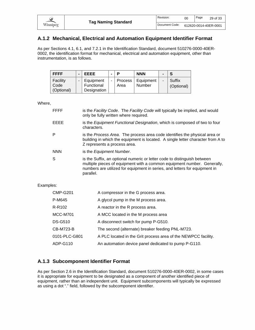
A.1.2 Mechanical, Electrical and Automation Equipment Identifier Format
As per Sections 4.1, 6.1, and 7.2.1 in the Identification Standard, document 510276-0000-40ER-0002, the identification format for mechanical, electrical and automation equipment, other than instrumentation, is as follows.
FFFF - EEEE - P NNN - S
Facility Code (Optional)
- Equipment Functional Designation
- Process Area
Equipment Number
- Suffix (Optional)
Where,
FFFF is the Facility Code. The Facility Code will typically be implied, and would only be fully written where required.
EEEE is the Equipment Functional Designation, which is composed of two to four characters.
P is the Process Area. The process area code identifies the physical area or building in which the equipment is located. A single letter character from A to Z represents a process area.
NNN is the Equipment Number.
S is the Suffix, an optional numeric or letter code to distinguish between multiple pieces of equipment with a common equipment number. Generally, numbers are utilized for equipment in series, and letters for equipment in parallel.
Examples:
CMP-G201 A compressor in the G process area.
P-M645 A glycol pump in the M process area.
R-R102 A reactor in the R process area.
MCC-M701 A MCC located in the M process area
DS-G510 A disconnect switch for pump P-G510.
CB-M723-B The second (alternate) breaker feeding PNL-M723.
0101-PLC-G801 A PLC located in the Grit process area of the NEWPCC facility.
ADP-G110 An automation device panel dedicated to pump P-G110.
A.1.3 Subcomponent Identifier Format
As per Section 2.6 in the Identification Standard, document 510276-0000-40ER-0002, in some cases it is appropriate for equipment to be designated as a component of another identified piece of equipment, rather than an independent unit. Equipment subcomponents will typically be expressed as using a dot “.” field, followed by the subcomponent identifier.
Tag Naming Standard
Revision: 00 Page 30 of 33
Document Code: 612620-0014-40ER-0001
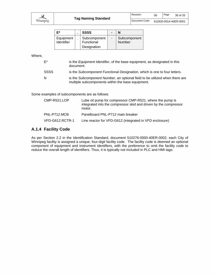
E* . SSSS - N
Equipment Identifier
. Subcomponent Functional Designation
- Subcomponent Number
Where,
E* is the Equipment Identifier, of the base equipment, as designated in this document.
SSSS is the Subcomponent Functional Designation, which is one to four letters.
N is the Subcomponent Number, an optional field to be utilized when there are multiple subcomponents within the base equipment.
Some examples of subcomponents are as follows:
CMP-R521.LOP Lube oil pump for compressor CMP-R521, where the pump is integrated into the compressor skid and driven by the compressor motor.
PNL-P712.MCB Panelboard PNL-P712 main breaker
VFD-G612.RCTR-1 Line reactor for VFD-G612 (integrated in VFD enclosure)
A.1.4 Facility Code
As per Section 2.2 in the Identification Standard, document 510276-0000-40ER-0002, each City of Winnipeg facility is assigned a unique, four-digit facility code. The facility code is deemed an optional component of equipment and instrument identifiers, with the preference to omit the facility code to reduce the overall length of identifiers. Thus, it is typically not included in PLC and HMI tags.
Tag Naming Standard
Revision: 00 Page 31 of 33
Document Code: 612620-0014-40ER-0001
Appendix B

Tag Naming Standard
Revision: 00 Page 32 of 33
Document Code: 612620-0014-40ER-0001
B.1 Standard Abbreviations and Acronyms
Table 3 – Standard Abbreviations
Abbreviation Description
Accum Accumulated / Accumulator
Act Action
Alm Alarm
Alt Altitude
Avail Available
Auto Automatic
Avg Average
Chan Channel
Cls Close
Cmd Command
Comm Communication
Compl Complete
Cont Continuous
Ctrl Control
Curr Current (eg. Current Selection)
CV Control Variable
Dest Destination
Dia Diameter
Dis Disable
Dly Delay
Elec Electrical
Enb Enable
Eqmt Equipment
Err Error
Gen General
Fail Failure
Fbk Feedback
Flt Fault
Fwd Forward
Hi High
In Input
Intlk Interlock (Input)
Intlked Interlocked (Output)
Lmt Limit
Lo Low

Tag Naming Standard
Revision: 00 Page 33 of 33
Document Code: 612620-0014-40ER-0001
Abbreviation Description
Op Operator
Opn Open
Out Output
PV Process Variable
Man Manual
Max Maximum
Mid Middle
Min Minimum
Num Number
Pos Position
RC Rate of Change
Rdy Ready
Req Request / Requested
Rem Remote
Rev Reverse
Rst Reset
Tgt Target
Sel Select / Selection / Selected
SP Setpoint
Vol Volume
Warn Warning
B.1.1 Additional References
Fluid commodity codes may also be used in the naming of classes, function blocks, parameters, and variables. Refer to Table 5-2 in the City of Winnipeg Identification Standard, document 510276-0000-40ER-0002 for the complete list of standard fluid commodity codes.