apparatus for constant-head solute transport and soil water characteristic determination
TRANSCRIPT
Apparatus for Constant-Head Solute Transport and Soil WaterCharacteristic Determination
H. W. Langner, J. M. Wraith,* W. P. Inskeep, H. M. Gaber, and B. Huwe
ABSTRACTWe developed a system to impose, maintain, and monitor constant
matric head (h ) and water content (0) within large soil cores duringsaturated or unsaturated flow. Critical elements include: (i) deliveryof water and chemicals to the column inlet using a modified diskpermeameter; (ii) paired time domain reflectometry (TDK) and trans-ducer tensiometer sensors; and (iii) solenoid valves at the outlet foruninterrupted negative pressure and simultaneous collection of largeeffluent volumes. Use of TDR and tensiometry provides detailedwater retention data and allows hydraulic conditions within the soilto be continuously monitored during single or multiple experimentsusing the same soil column. Our experiences have emphasized theneed to measure soil column h rather than infer its status based onapplied pressure.
MANY INVESTIGATIONS concerning unsaturated soilwater or chemical movement require imposition
of steady (or near-steady) state hydraulic conditions tosoil columns. This is often addressed by controlling therate of solution inflow at the upper boundary and ad-justing head (e.g., by applying vacuum with a porousplate) at the lower boundary (van Genuchten and Wier-enga, 1986; Gaber et al., 1995). Alternatively, adjustablepressure heads may be applied to both ends of the col-umn (e.g., Nielsen and Biggar, 1961; Seyfried and Rao,1987; Jardine et al., 1993; Munyankusi et al., 1994;Magesan et al., 1995; Vogeler et al., 1996). While anadvantage of the first approach is ease in switching be-tween eluent sources, the latter facilitates setting a de-sired matric head (h) at the column inlet. If equal pres-sure heads are applied to the top and bottom of thecolumn, the overall hydraulic potential energy gradientalong the vertical column is unity. In a homogeneousporous medium, this will result in a uniform, steady-state matric head with water flow driven by the unitgradient gravitational potential only. However, soil col-umns will often deviate from unit gradient because ofheterogeneities in the pore system with depth; this isparticularly true for intact or "undisturbed" soils. Porediscontinuities at the interface of the porous plate andsoil that result in low interfacial hydraulic conductivitymay also interfere with establishment of unit gradientwithin soil cores. In this situation, effects of a drop inh above the porous bottom plate can potentially beavoided by measuring h within the core and adjustingthe bottom plate pressure. Failure to achieve or to main-tain constant-head steady flow conditions in soil col-
H.W. Langner, J.M. Wraith, W.P. Inskeep, and H.M. Gaber, Plant,Soil and Environmental Sciences Dep., Montana State Univ., Boze-man, MT 59717-0312; and B. Huwe, Dep. of Soil Science and SoilGeography, Univ. of Bayreuth, Bayreuth 95440, Germany. Contribu-tion no. J-4077 from Montana Agric. Exp. Stn. Received 18 Oct. 1996.*Corresponding author ([email protected]).
Published in Soil Sci. Soc. Am. J. 62:110-113 (1998).
umns will result in inaccurate or inappropriate resultsand conclusions.
Another common problem during soil column leach-ing experiments involves changes in soil properties dur-ing the course of an investigation (e.g., Vandevivere andBaveye, 1992). Continuous monitoring of 0 and h canalert an investigator to changes in the 0(/z) relationshipthat may affect experimental results.
We designed and tested a system to impose, maintain,and monitor uniform soil matric head during miscibledisplacement experiments in large intact soil cores. Inaddition, during column conditioning (sequential wet-ting and drying) a detailed soil water characteristic rela-tionship may be determined in situ by simultaneousmeasurements of 0 and h using TDR and pressure trans-ducer tensiometry (Wraith and Baker, 1991; Hudson etal., 1996). Novel aspects of our approach include aneffective means to ensure that unit gradient flow condi-tions are established and maintained, simultaneous col-lection of large effluent volumes without interruption ofthe outlet pressure, and continual monitoring of columnQ(h) during the course of single or multiple experiments.We describe the system for constant-head solute trans-port and 6(h) determination within an operable wetnessrange of about h = 0 to -80 cm, discuss some of itsadvantages and disadvantages compared with other ap-proaches, and briefly illustrate its application to moni-toring and evaluating miscible displacement of tritiatedwater in large intact soil cores. While not specificallyaddressed here, this system may also be used to controlsoil water content or water flux density (/w) during soilcolumn experiments. Control of h, 0, or /w may be appro-priate or advantageous depending on experimental ob-jectives. Other potential areas of application are toquantify the column hydraulic conductivity [^(0)] rela-tions (e.g., Wraith and Baker, 1991; Hussen et al., 1994),and to monitor the movement of ionic solutes using theembedded TDR probes (Wraith et al., 1993; Vogeler etal., 1996; Risler et al., 1996) under controlled and well-characterized column transport conditions.
MATERIALS AND METHODSWe obtained intact soil cores (15.2-cm diameter, 30-cm
length) from the A.H. Post Experimental Farm near Bozeman,MT, by forcing beveled and lubricated polyvinyl chloride(PVC) pipe into the soil using a hydraulic core sampler. Soilsat this location are classified as Amsterdam silt loam (fine-silty, mixed Typic Haploboroll). Transducer tensiometers (0.6-cm width, 6.5-cm length one-bar high-flow ceramic cups, SoilMoisture Equipment Co.1, Santa Barbara, CA; Model 141PCGsensors, Micro Switch, Freeport, IL), fabricated in our labora-tory, were horizontally inserted in the column at depths of 9and 21 cm (Fig. 1). We used a Model 21X data logger (Camp-
1 Mention of specific products or company names is for the benefitof the reader, and does not imply endorsement.
110
LANGNER ET AL.: APPARATUS FOR CONSTANT-HEAD SOLUTE TRANSPORT 111
bell Scientific, Logan, UT) to switch a relay controlling theexcitation voltage of 13.7 V from an external power source,and to collect transducer output data. Pressure transducerswere individually calibrated at the same constant (essentialto achieve transducer output fluctuations corresponding toh < I cm) excitation voltage using a water manometer, and thecalibrations were checked between experiments. Transduceraccuracy and response time were enhanced by the use of rigidAl tubing and daily replacement of tensiometer fluid withdegassed water. A 10-cm-long three-rod TDR probe was in-stalled normal to each tensiometer and was offset by about1-cm vertical distance. The TDR probes were connected to aTektronix (Beaverton, OR) Model 1502C cable tester via acoaxial multiplexer (SDMX50, Campbell Scientific). Sensorports were sealed using silicone sealant.
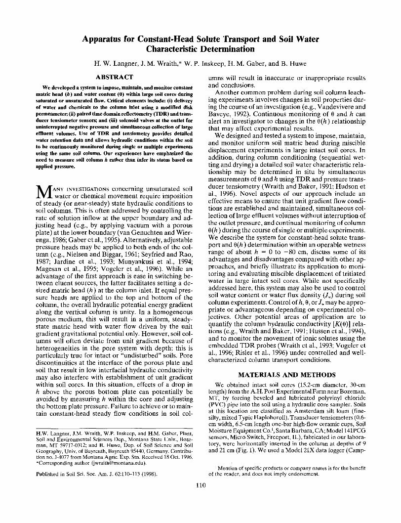
A modified disk permeameter (Perroux and White, 1988)base allowed eluent to be applied at the top of columns undercontrolled ponded or negative supply pressure (Fig. 1). Air-entry pressure of the permeameter membrane (40-fjim nylonmesh, Soil Measurement Systems, Tucson, AZ) was about—30 cm. One three-way and one two-way valve (EllipticValves 0.5-in. NPT, Cole Farmer Instrument Co., Niles, IL)connected in series allowed switching between different eluentsolutions. Switching eluents by replacing the permeameter(Magesan et al., 1995) was not feasible with our test soil be-cause of the potential for mechanical damage to the soil sur-face layer and subsequent changes in the soil column hydrauliccharacteristics. All solution inlet lines that simultaneouslytransmitted liquid and air required a flow diameter of at least1.0 cm to allow free opposite movement of the phases, or airand solution lines needed to be separated, e.g., by insertinga smaller air tube into a larger liquid-filled tube. The permea-meter was equipped with a flushing port similar to that ofSeyfried and Rao (1987), which facilitated rapid exchange ofeluent sources without measurable supply pressure fluctua-tion. To switch between eluent solutions, the valve connectingto the eluent reservoir was closed. Then, a pressure slightlylower than the pressure set with the Mariotte device wasapplied to the flushing port and the appropriate valve to thenew reservoir was slowly opened. To minimize mixing ofeluent solutions within the permeameter base, the valve con-trolling the new eluent reservoir was opened and closed sev-eral times while solution was continuously removed throughthe flushing port.
The radius of the infiltrometer base was about 0.5 cm lessthan that of the soil surface, allowing air exchange as thecolumn was wetted or drained. Additional air-entry ports atseveral depths in the column wall did not appear to affectwetting and draining and were omitted after preliminary stud-ies. To ensure good contact between the soil and infiltrometermembrane, we severed any aboveground vegetative residue,slightly leveled the soil surface if necessary, and added a1-cm layer of graded fine silica sand (Grade 70 sieved through149-(xm screen).
The column base was designed to allow simultaneous appli-cation of negative pressure and collection of large effluentvolumes without interruption of pressure at the column base.The lower surface of the soil rested on a porous stainless steelplate (Mott Metallurgical Corp., Farmingdale, CT) having anair-entry pressure of 300 cm and was sealed with rubber O-rings in an acrylic end cap. Outlet pressure was controlled bya vacuum regulator (Model 44-20, Moore Products Co., SpringHouse, PA) and measured with a water manometer. Columneffluent was stored in a glass reservoir between two three-way solenoid valves (Model B14DK1030, Skinner Valve Div.,New Britain, CT) during collection mode (position a in Fig.1). After tubes advanced in the fraction collector (Retriever
Permeameter Base
Venting Port- Transducer
FractionCollector
WaterMano-meterFig. 1. Schematic diagram of soil column control and monitoring sys-
tem with valves in collecting mode (a) and sampling mode (b),and a detailed schematic of the pressure transducer tensiometers.Epoxy was used to seal the connections between ceramic cup,aluminum tubing, and three-way valve for tensiometers.
II, ISCO, Lincoln, NE) under the column, a timed controllerswitched the valves to sampling mode (position b) and allowedthe collected effluent to rapidly drain into a sample tube. Thesolenoid valves were set back to the collection position about10 s later. Soil column pressure fluctuations during a collec-tion-sampling cycle were dependent on the amount of liquidin the glass reservoir. Since the net bottom plate pressure wasoffset from the pressure at the vacuum regulator by the heightof the water column in the collection reservoir, we notedfluctuations in matric head of 1 to 2 cm at the lower tensiome-ter. These fluctuations could be reduced by shortening thecollection cycle and thus reducing the depth of water in thereservoir. However, this would increase the number of sam-pling tubes collected. A reservoir with wider diameter thusseems a likely solution to this issue.
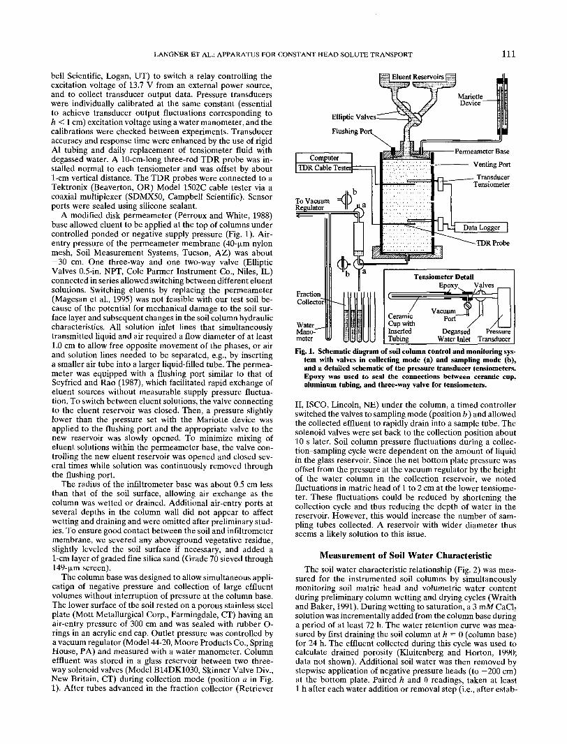
Measurement of Soil Water CharacteristicThe soil water characteristic relationship (Fig. 2) was mea-
sured for the instrumented soil columns by simultaneouslymonitoring soil matric head and volumetric water contentduring preliminary column wetting and drying cycles (Wraithand Baker, 1991). During wetting to saturation, a 3 mM CaCl2solution was incrementally added from the column base duringa period of at least 72 h. The water retention curve was mea-sured by first draining the soil column at h = 0 (column base)for 24 h. The effluent collected during this cycle was used tocalculate drained porosity (Kluitenberg and Horton, 1990;data not shown). Additional soil water was then removed bystepwise application of negative pressure heads (to —200 cm)at the bottom plate. Paired h and 9 readings, taken at least1 h after each water addition or removal step (i.e., after estab-
112 SOIL SCI. SOC. AM. J., VOL. 62, JANUARY-FEBRUARY 1998
0.28
-10 -20 -30 -40 -50 -60 -70 -80
Matric Head (cm)Fig. 2. Measured wetting and drying curves for one TDR waveguide-
tensiometer pair. The wetting and drying limbs were individuallyfit to van Genuchten's (1980) water content-pressure head,8(A), model.
lishing quasi-static conditions; Vachaud et al., 1972), were usedto fit a model describing Q(h) (van Genuchten, 1980) usingnonlinear least squares optimization. Equilibration times maybe altered at the discretion of the user. Tensiometer readingswere adjusted for the height difference between tensiometercups and TDR probes.
Setting Unit Head GradientFollowing wetting from the base, the disk permeameter
supply pressure was adjusted to the desired column matrichead (h). Increasingly negative pressure was then applied atthe base until the top and bottom tensiometer readings wereequal, i.e., unit gradient conditions had been reached. Achiev-ing equivalent top and bottom tensiometer readings underunsaturated conditions (h < 0) usually required the bottomplate pressure head to be 5 to 25 cm lower than the targetcolumn h value. Due to presumed alteration in soil pore ar-rangement during transport experiments, tensiometer andTDR readings sometimes changed with time. Periodic adjust-ments of the bottom plate pressure head on the order ofa few millimeters to several centimeters were necessary tomaintain constant matric head throughout an experiment.These adjustments were required at intervals of several daysat h < —10 cm, and every few hours at h between —2 and-5 cm. We were able to maintain measured deviations fromthe target h value to <1 cm for complete transport experimentslasting 1 or 2 wk.
Unit gradient hydraulic conditions could not be establishedunder saturated conditions (h — 0) because of insufficientflow rate through the bottom porous plates. Specifically, ourintact test columns contained numerous large (diameter ofseveral millimeters) and continuous pores that were waterfilled when the permeameter head was set to zero. Resultinghigh soil hydraulic conductivities caused ponding above thebottom porous plate even when low pressures were appliedto the plate. Saturated experiments were therefore performedat a permeameter supply head of 0 cm and bottom platepressure head of -50 cm, which resulted in positive heads atthe tensiometers. Our system design was restricted to therange between ponding and h = — 25 cm, with the limitingfactor being the air-entry pressure of the disk permeametermembrane. Use of finer mesh or alternative materials wouldextend this range.
Monitoring Column Hydraulic ConditionsIt is often desirable to conduct multiple transport experi-
ments using the same soil core because of variability in physical
0.00
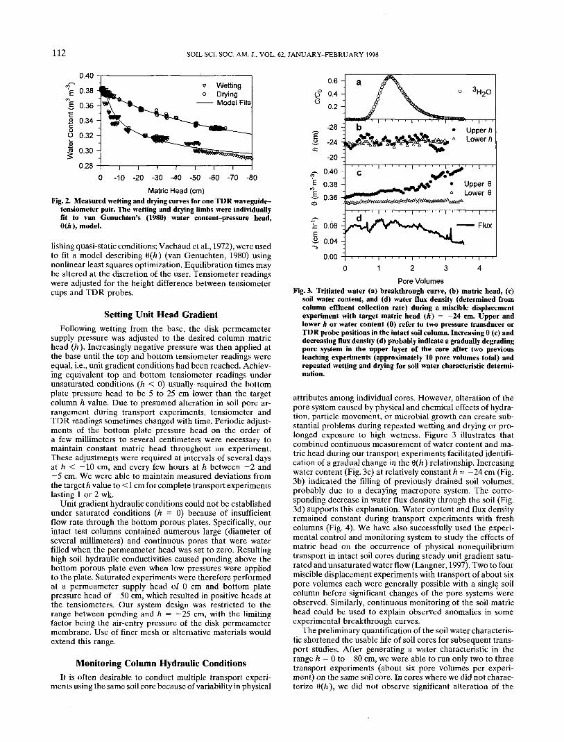
Pore VolumesFig. 3. Tritiated water (a) breakthrough curve, (b) matric head, (c)
soil water content, and (d) water flux density (determined fromcolumn effluent collection rate) during a miscible displacementexperiment with target matric head (A) = -24 cm. Upper andlower h or water content (6) refer to two pressure transducer orTDR probe positions in the intact soil column. Increasing 6 (c) anddecreasing flux density (d) probably indicate a gradually degradingpore system in the upper layer of the core after two previousleaching experiments (approximately 10 pore volumes total) andrepeated wetting and drying for soil water characteristic determi-nation.
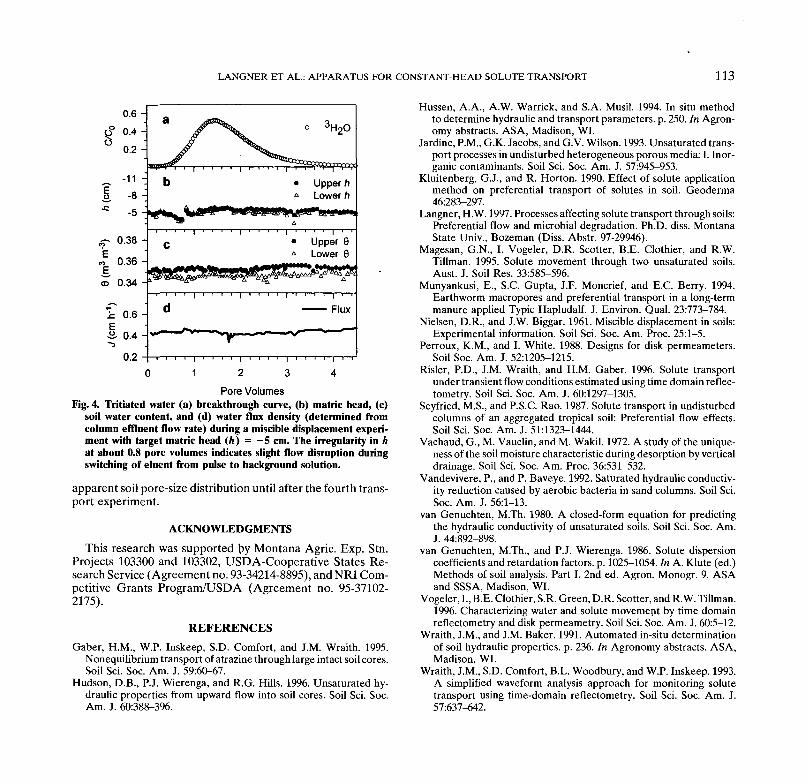
attributes among individual cores. However, alteration of thepore system caused by physical and chemical effects of hydra-tion, particle movement, or microbial growth can create sub-stantial problems during repeated wetting and drying or pro-longed exposure to high wetness. Figure 3 illustrates thatcombined continuous measurement of water content and ma-tric head during our transport experiments facilitated identifi-cation of a gradual change in the %(h) relationship. Increasingwater content (Fig. 3c) at relatively constant h~ -24 cm (Fig.3b) indicated the filling of previously drained soil volumes,probably due to a decaying macropore system. The corre-sponding decrease in water flux density through the soil (Fig.3d) supports this explanation. Water content and flux densityremained constant during transport experiments with freshcolumns (Fig. 4). We have also successfully used the experi-mental control and monitoring system to study the effects ofmatric head on the occurrence of physical nonequilibriumtransport in intact soil cores during steady unit gradient satu-rated and unsaturated water flow (Langner, 1997). Two to fourmiscible displacement experiments with transport of about sixpore volumes each were generally possible with a single soilcolumn before significant changes of the pore systems wereobserved. Similarly, continuous monitoring of the soil matrichead could be used to explain observed anomalies in someexperimental breakthrough curves.
The preliminary quantification of the soil water characteris-tic shortened the usable life of soil cores for subsequent trans-port studies. After generating a water characteristic in therange h = 0 to — 80 cm, we were able to run only two to threetransport experiments (about six pore volumes per experi-ment) on the same soil core. In cores where we did not charac-terize Q(h), we did not observe significant alteration of the
LANGNER ET AL.: APPARATUS FOR CONSTANT-HEAD SOLUTE TRANSPORT 113
Pore VolumesFig. 4. Tritiated water (a) breakthrough curve, (b) matric head, (c)
soil water content, and (d) water flux density (determined fromcolumn effluent flow rate) during a miscible displacement experi-ment with target matric head (h) = -5 cm. The irregularity in hat about 0.8 pore volumes indicates slight flow disruption duringswitching of eluent from pulse to background solution.
apparent soil pore-size distribution until after the fourth trans-port experiment.
ACKNOWLEDGMENTS
This research was supported \>y Montana Agric. Exp. Stn.Projects 103300 and 103302, USDA-Cooperative States Re-search Service (Agreement no. 93-34214-8895), and NRI Com-petitive Grants Program/USDA (Agreement no. 95-37102-2175).