api subcommittee 6mycommittees.api.org/standards/ecs/sc6/meeting materials/2009/feb 3... · 7. api...
TRANSCRIPT
MINUTES
Meeting of the API SUBCOMMITTEE ON VALVES
AND WELLHEAD EQUIPMENT (API SC6)
at the
2009 Winter Meeting on Oilfield Equipment and Materials
of the
AMERICAN PETROLEUM INSTITUTE
Host: Shell Woodcreek Park Offices (Located in West Houston's Energy Corridor District)
150A North Dairy Ashford Houston, TX
February 3, 2009
***
David Cole, Chairman Ed Baniak, API Staff Representative
Roy W. Benefield, Secretary
AMERICAN PETROLEUM INSITUTE Upstream Standards 1220 L Street, NW
Washington, DC 20005

API Subcommittee 6 Valves and Wellhead Equipment
Winter 2009 Meeting Minutes
Date: Tuesday, February 3, 2009 Time: 9:00AM to 2:00 PM Location: Shell Woodcreek Park Offices (Located in West Houston's Energy Corridor District)
150A North Dairy Ashford Houston, TX
Items:
1. Call to Order – David Cole, Chairman, called the meeting to order. Safety comments were made.
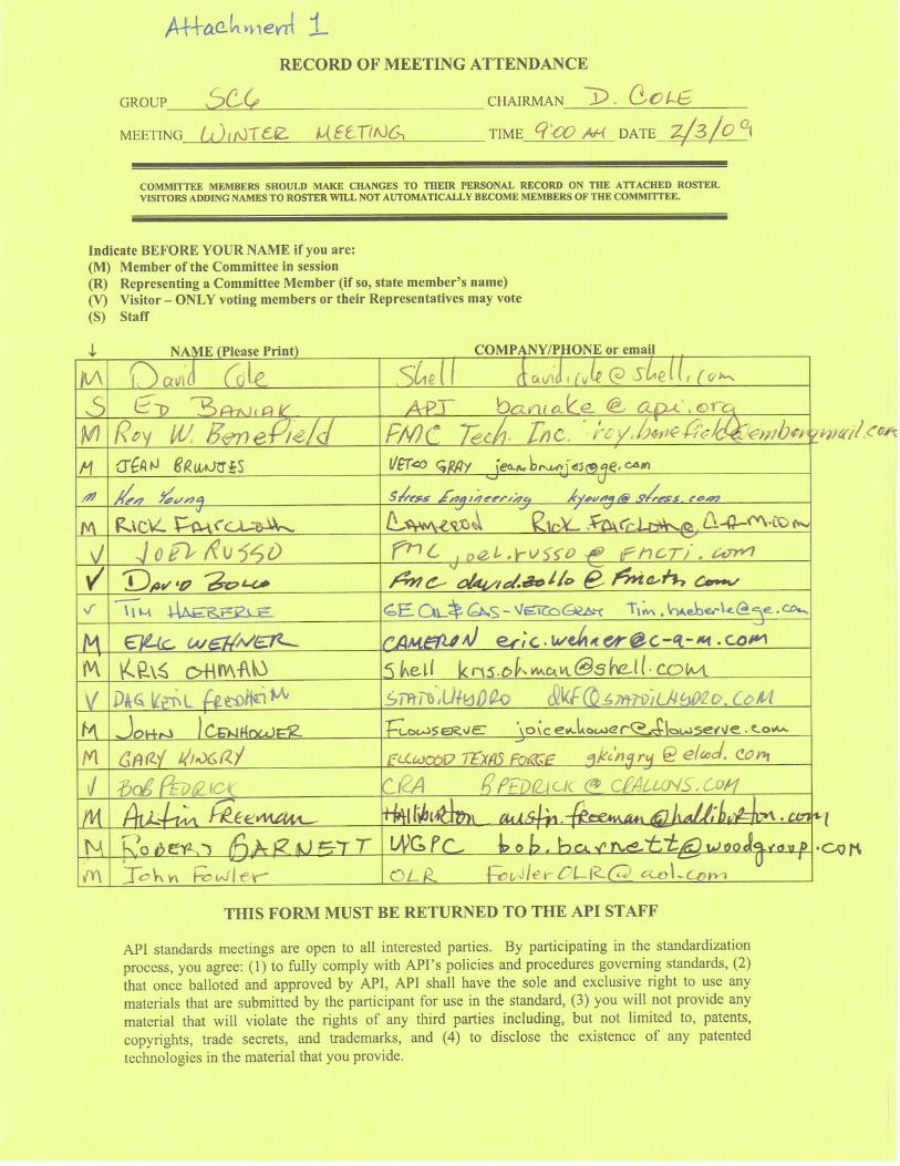
2. Attendance – Ed Baniak – sign up sheet was passed for attendance (See Attachment 1).
3. Adoption of the Agenda – David Cole Motion, Made, seconded and passed to accept the agenda, revision 3, as sent out.
4. Establish a Quorum– SC6 Membership – David Cole – A quorum was present.
5. Ratify the Summer 2008 Calgary meeting minutes (attached, see API website for attachments) – David Cole – Minutes are posted on the Web site. Motion made, seconded, passed to approve as published.
6. Review 2008 ballot outcomes – Ed Baniak – The following ballots were discussed.
a. Ballot 1420 - Repair & Remanufacture (Annex Q) – Published as Addendum 3, December 2008 – Passed with comments and editorial changes. Is acceptable to API legal counsel.
b. Ballot 1442 - Addition of Filler Grease – Published as part of Addendum 2, December 2008 –
Passed. c. Ballot 1472 - Reaffirmation of API 6FD – Document Reaffirmed d. Ballot 1475 - Changes to TR 6AF2 – Document format updated and changes published. e. Ballot 1476 - Changes to TR 6AF – Document format updated and changes published. f. Ballot 1513 - Changes to API 6A Table 7 – Published as part of Addendum 2, December
2008 g. Ballot 1564 – Bullplug Coatings, API Spec 6A – Published as part of Addendum 4, December
2008 – To be included in ISO 10423 FDIS. h. Ballot 1565 – Bullplug Dimensional Allowance, API Spec 6A – Published as part of
Addendum 4, December 2008 - To be included in ISO 10423 FDIS.

7. API Ballot System – Ed Baniak
a. Recent (2009) SC6 Ballots – Ballot 1587 (Changes to API 6FC) – Ballot 1587 (reaffirming API 6FC) The Spec 6F (fire test) series was reaffirmed in 2006. However, due to an oversight that precedes the chair or the API staff involvement in SC6, technical comments to 6FC were never resolved. Ed Baniak is working with the submitter of the comments to resolve the ballot comments.
b. Improvements to ballot system. – As a result of an ANSI audit, the API ballot system is being
changed. These changes will benefit subcommittees who with diverse user groups and have managed with separate voting groups. SC6 could change from separate 6A and 6D voting groups, but not likely in the short term. The change is that to obtain the required 50% of eligible voters required by API, the 50% voting will include abstentions in the calculation toward 50%. The requirement to have 2/3 of ballots cast to be in the affirmative has not changed (must be 2/3 of votes cast either yes or no).
8. Report/Updates from Task Groups
a. 20K Flanges - Shyam Patel – John Fowler reported for Shyam. See Attachment 2. New gasket design is being considered. Hydril has designed a very large flange with larger than normal bolting (3.75 diameter and higher strength materials). – non API). Design may include a lip-type gasket in lieu of the BX-164. It would help to have high-strength bolting. BX-164 gasket design is being evaluated for the 20K applications.
b. Use of Castings -Sterling Lewis – See Attachment 3. Two major issues that kept ISO and
API from being identical. Cast verses forge is one of them. (Repair was the other.) ISO 10423 PSL 3 does not allow castings. Wording will be changed to advise against castings in 6A Annex A for PSL 3 and 4, and to provide guidance for use of castings. Can a manufacturer monogram and PSL 3 cast product? Yes, where applicable. ISO still says no casting for PSL 3. Wrought products will be specified for PSL 3 and 4 mandrel hangers. Text needs to designate PSL 3G as well as PSL 3. Ed pointed out that this is a technical change and may want to handle it as a Regional Annex, because ISO 10423 is in FDIS stage. It is preferred to be a normative text in the body of the ISO document. Could be a second DIS to 10423, but will open up all changes for comment. Will have to resolve with ISO for agreement. Action is for Sterling to get final language and send to ISO, and for Ed to contact ISO as to how and when to revise 10423 (if ISO likes the change).
c. API 6HP - Earl Shanks – Ken Young reporting for Earl. See Attachment 4. Next meeting is
to be scheduled. Presented to ECS at Winter Conference. Some delay to convene another meeting because of process issues. Earl reported that these overheads are being used to explain the document to the industry on design validation and verification. This document is intended to be a reference for the API communities. There is concern that this document is being referenced in the industry before it is ready.
d. Pipeline Valves - Rick Faircloth – See Attachment 5. Updates on 6D. Some interpretations.
Also will be looking at calibration and quality control issues. Reference ISO 7268 document that used “pn” numbers. The document is in ballot and “pn” numbers are being changed. This may cause problems and some are not happy. We want to stop reference to ISO 7268 in our documents. Ed says this might be done by an editorial change. Action by Ed: It was requested that the ISO 7268 communication (email) with ISO be put on the Web site or attached to the minutes of this meeting (Completed – See Attachment 6).
e. ASME Section 8 Div. II changes - John Fowler – See Attachment 7. Comments are being considered. They will enlist the Assistance of 16A, 16C and 17D people to help.

f. API 6A718 - Tim Haeberle – See Attachment 8. There was a meeting January 2. There was good interest and membership. Guidance from SC6 is requested on validation requirements need in API Spec 6A718 and what does it mean. API Q1 Section 7.5.2 requires a procedure. It was agreed that this applies to product and process specifications, and not necessarily material specifications. Ed suggested that API Spec 6A718 be designated as a “standard” instead of a “specification.” Process validation would then not be an applicable. There was some objection to this. There was also discussion concerning competence of testing and calibration laboratories. It was suggested that some sections of ISO/IEC 17025 be inserted in the API Spec 6A718, as applicable. This should probably be in the 6A parent document and driven by that document. The Work Group will continue to meet and hopes to have a completed ballot by the June meeting.
g. API 6AV1 - Eric Wehner – Eric reported that there is still work to be done on this issue. Southwest Research (San Antonio) is currently the only resource on this specification.
9. ISO 10423 Status – Ries Langereis – See Attachment 9. Eric Wehner reported for Ries. An action item list was reviewed.
10. API and ISO Cooperation - David Cole & Ries Langereis – In the short term, the plan will be to attempt to have representation from both API and ISO on any work groups affecting the shared documents. In a separate item, David Cole reported that API ECS is proposing formalizing the process to determine whether new documents and document revisions are handled by API alone or by API/ISO. The intent is for each subcommittee to look at the need for and the resources to support adopt-back. There appears to be little difference in what is proposed and what SC6 has been doing
11. New Business
a. AWHEM Reports - Metallic Material Limits for Wellhead Equipment Used in High Temperature for API 6A And 17D Applications: Phase I (dated 4-04); Phase II (dated 9-06); Phase III (dated 11-08) [Abstracts below] Ed reported on the status of this project. The abstracts were attached to the agenda of this meeting. Is there a need for SC6 task group or work group to utilize these reports? This could be used in Appendix G for de-rating of materials. Some of this is in ISO 10423 already. Action: Austin Freeman volunteered to lead in the effort to evaluate the status and determine a path forward (concerning AWHEM Reports - Metallic Material Limits for Wellhead Equipment Used in High Temperature for API 6A And 17D Applications: Phase I (dated 4-04); Phase II (dated 9-06); Phase III (dated 11-08)), with the help of Tim Haeberle. AWHEM should be requested put these reports in final form for publication. Eric will bring this up at AWHEM. b. SC6 PER-15K Membership Solicitation – ECS solicited each impacted SC to ensure that they had a liaison with the PER-15K effort. Shyam Patel, Ken Young and Morg Bruck volunteered to represent SC6 in this effort. c. SC6 is to review product specification licensing categories to ensure their accuracy – We need to go through 6A and determine what products do not include design activities (i.e., ring gaskets, blind flanges, studs and nuts, etc.) We need to identify the products

that are manufacture designed products verse commodity products (i.e., standards designed products). Is the facility an assembler, tester, etc. Eric Wehner volunteered to develop a list of API Spec 6A products that do not require manufacture design.
d. SC6 determined that there were no additional processes requiring validation other than the default processes of welding, heat treating and NDE. e. Color-coding requirements of SC6 documents – SC6 needs to notify Monogram Program – David reported that c, d and e are requests from Committee 18. Ed reported on the request from SC18 and what they mean. Action: SC 6 is to determine which documents are to be color-coded. (6A, 6D, 6H, and 6DSS.) SC6 determined that only 6DSS requires color coding at this time. 6A will be revisited later when newest revision is issued f. Other – None Identified.
12. Adjourn (Next Meeting: June 2009, Westminster [Denver], Colorado)
Action Item Summary:
1. Action is for Sterling Lewis to get final casting language and send to ISO, and for Ed Baniak to contact ISO as to how and when to revise 10423 (if ISO likes the change).
2. Action by Ed: It was requested that the ISO 7268 communication (email) with ISO be put on the Web site or attached to the minutes of this meeting (Completed, see Attachment 6)
3. Austin Freeman volunteered to lead in the effort to evaluate the status and determine a path forward (concerning AWHEM Reports - Metallic Material Limits for Wellhead Equipment Used in High Temperature for API 6A And 17D Applications: Phase I (dated 4-04); Phase II (dated 9-06); Phase III (dated 11-08)), with the help of Tim Haeberle. AWHEM should be requested put these reports in final form for publication. Eric will bring this up at AWHEM
4. Eric Wehner volunteered to develop a list of API Spec 6A products that do not require manufacture design.

AWHEM Reports (Item 11a, New Business Above)
METALLIC MATERIAL LIMITS FOR WELLHEAD EQUIPMENT USED IN HIGH
TEMPERATURE FOR API 6A AND 17D APPLICATIONS: Phase I (April 04); Phase II (September 2006); Phase III (November 2008)
PHASE I Abstract: This API-funded project was conducted by a Task Group charged by the Association of Well Head Equipment Manufacturers (AWHEM). The Task Group examined mechanical properties of metallic materials used for API 6A and 17D wellhead equipment for service above 250ºF. Six different materials meeting API 6A, PSL 3 and 75 Ksi conditions were supplied “in condition” by a variety of suppliers. Yield strength reduction ratios at temperatures of 300, 350 and 400ºF from “mid-radius” specimens were determined. As a result of testing, yield strength reduction ratios ranged from 93% at 300ºF to 89% at 400ºF by averaging results of heats for each type of material. Materials such as AISI 4130 showed the greatest variability due to hardenability issues. These results are intended to amplify data shown in API 6A, Appendix G. (11 page report)
PHASE II Abstract: This API-funded project was conducted by a Task Group charged by the Association of Well Head Equipment Manufacturers (AWHEM). The Task Group examined mechanical properties of metallic materials used for API 6A and 17D wellhead equipment for service above 250ºF. Phase I of the project tested six different Low Alloy materials meeting API 6A, PSL 3 and 75 Ksi conditions which were supplied “in condition” by a variety of suppliers. Similarly Phase II examined five different corrosion resistant alloys (CRAs). Yield strength reduction ratios at temperatures of 300, 350 and 400ºF from “in condition” specimens were determined. As a result of testing, yield strength reduction ratios ranged from 99% at 300ºF to 76% at 400ºF by averaging results of heats for each type of material. Supplier-furnished data was used for some of the material due to the difficulty in obtaining CRA in tight market conditions. Test results from some labs on certain material produced widely varying results and were removed. Some bad data were due to movement of the specimen or extensometer extensions during testing. Shortages of material precluded retesting. (15 page report) PHASE III Abstract: This API-funded project was conducted by a Task Group charged by the Association of Well Head Equipment Manufacturers (AWHEM). The Task Group examined mechanical properties of metallic materials used for API 6A and 17D wellhead equipment for service above 250ºF. The maximum test temperature for mechanical properties was 450°F. The work reported here investigates the short term effect of temperature on the mechanical properties and any long term effects at these temperatures on the microstructure of these age-hardenable CRA alloys is outside the scope of this work. Phase I of the project tested six different Low Alloy materials meeting API 6A, PSL 3 and 75 Ksi conditions which were supplied “in condition” by a variety of suppliers. Phase II tested five different corrosion resistant alloys where the two alloys, nickel alloys 925 and 625Plus/725, failed to achieve a correlation of elevated temperature properties. Phase III was approved by API for a new round of testing on nickel alloys 925 and 625Plus/725. Yield strength reduction factors at temperatures of 300, 350 and 450ºF from “in condition” specimens were determined. As a result of testing, yield strength reduction factors ranged from 0.93 at 300ºF to 0.89 at 450ºF by averaging results of heats for each type of material. The results from Phase III were shown to be in good agreement with supplier-furnished data for the same alloys. (9 page report)


API 20K Flange Design Task Group
API SC6 Task Group
Date: February 2, 2009.
Attachment 2

2
Task Group Status Report
Task Group met only one time in August 08, since June Standardization conference.
• Continued work on discussing probable solutions to Design challenges (reported in June 08), from preliminary static load design i.e. sizing of flange.
• Preliminary Flange Design is considered too large considering practical aspects such as large foot print, very large bolt diameter and very high bolt torque and resulting heavy equipment design.
• Performed comparative study of bolt sizes in existing 15K & 20K API Flanges. Only general observation was made that for 18-3/4”-20K Flange Design will need High Strength or CRA HS bolting.

3
Task Group Status Report
• BX-164 Gasket is inadequate. New Gasket is needed.
− Existing API BX Gaskets were designed per Eichenberg’s method. Adopted in API 6A (Grandfathered). No references to Design Validation Testing.
− Gasket Design and Validation Method to be determined.
• Flange Design Method/Allowable being reviewed. API 6A + ASME Sect VIII (1994 Edition referenced in API 6A) or ASME Sect VIII, 2007 Edition.
Task Group Concerns:
• Flange Design Method & Allowable may differ from present API 6A Flanges.
• No past references known for existing Gasket validation procedure.

API 6A Workgroup on
PSL 3 Castings
February 3, 2009
Castings allowed in 6A but not in ISO 10423 at PSL 3 and above.
Attachment 3

Status
Work Group meeting was held November 2008
Proposed wording was circulated in workgroup, January 2009
Propose workgroup will submit ballot wording that would:
Provide additional user guidance for cast bodies in Annex A
Accept ISO wording for prohibiting use of cast PSL3 and PSL4 mandrel hangers
Prohibit use of PSL 4 castings for bodies, bonnets, end and outlet connections
Provide additional restriction for repair of casting defects in PSL3 bodies

Two Trains of Thought
Restrict QualityCastings may be inappropriate for some service conditions. Higher PSL levels are normally associated with more severe service conditions (Figure A.3). Limiting the available PSL levels will prevent use in severe service conditions.
Restrict UseUser is responsible to ensure products purchased are appropriate for service conditions. Limiting the PSLs does not limit/provide service conditions guidance for castings. User may wish for higher quality requirements for castings in the same service conditions (volumetric NDE & 100% surface NDE). Allowing PSL 3 castings will enable user to specify the desired level of quality for intended service.
API 6A is a manufacturing specification. The selection guide Annex A is informative
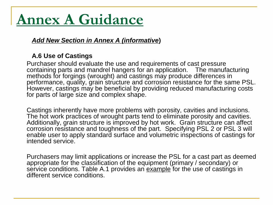
Annex A GuidanceAdd New Section in Annex A (informative)
A.6 Use of Castings
Purchaser should evaluate the use and requirements of cast pressure containing parts and mandrel hangers for an application. The manufacturing methods for forgings (wrought) and castings may produce differences in performance, quality, grain structure and corrosion resistance for the same PSL. However, castings may be beneficial by providing reduced manufacturing costs for parts of large size and complex shape.
Castings inherently have more problems with porosity, cavities and inclusions. The hot work practices of wrought parts tend to eliminate porosity and cavities. Additionally, grain structure is improved by hot work. Grain structure can affect corrosion resistance and toughness of the part. Specifying PSL 2 or PSL 3 will enable user to apply standard surface and volumetric inspections of castings for intended service.
Purchasers may limit applications or increase the PSL for a cast part as deemed appropriate for the classification of the equipment (primary / secondary) or service conditions. Table A.1 provides an example for the use of castings in different service conditions.

NEW
TABLE A.1
Part
Rated
Working
Pressure
(psi)
NACE MR-
0175 / ISO
15156
H2S
> 0.05 psia
High H2S
Concentration
> 70 ppm
Classifi-
cation
Well Type PSL
Forged Cast
Bodies
> 103,5
MPA (15000
psi)
NACE or non-
NACEAny level
Primary &
Secondary
Gas PSL 3G Not Allowed
Primary Oil PSL 3
Secondary Any Well PSL 3
Bodies69.0 MPA
(10000 psi)NACE Yes
Primary Gas PSL 3G Not allowed
Oil PSL 3
Secondary Any Well PSL 2 PSL 3
Bodies69.0 MPA
(10000 psi)NACE No
Primary Gas PSL 3 Not allowed
Oil PSL 2
Secondary Any Well PSL 2 PSL 3
Bodies<69.0 MPA
(10000 psi)Non-NACE NA
Primary Gas PSL 3 PSL 3G
Oil PSL 2 PSL 3
Secondary Any Well PSL 2 or PSL 1 PSL 2
Bodies<34.5 MPA
(5000 psi)NACE yes
Primary Gas or
Oil
PSL 2 Not Allowed
Secondary Any Well PSL 2 PSL 3
Bodies<34.5 MPA
(5000 psi)NACE No
Primary Gas PSL 3 PSL 3G
Oil PSL 2 PSL 3
Secondary Any Well PSL 2 or PSL 1 PSL 2
Bodies<35.5 MPA
(5000 psi)Non NACE NA
Primary Gas PSL 1 PSL 3G
Oil PSL 1 PSL 2
Secondary Any Well PSL 1 PSL 1

Cast Mandrel Hangers
5.3 Mandrel tubing and casing hangers5.3.2.1 Casting practicesa) PSL 1 requirements
All castings used for hanger mandrels shall meet applicable requirements of Clause 5 and Clause 7.
Remove Annex O wording
b) PSL-2-4 requirements
The requirements for PSL 2-4 are identical to the requirements for PSL1
Use ISO wording
b) PSL 2 requirements
The requirements for PSL 2 are identical to the requirements for PSL 1. In addition the manufacturer shall document foundry practices which establish limits for sand control, core making, rigging, melting, heat treatment and NDE to ensure repeatability in providing castings which meet the requirements of this International Standard.
c) PSL 3 and PSL 4
Wrought products shall be used.
Cast Bodies, Bonnets & End Connections
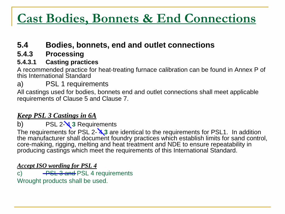
5.4 Bodies, bonnets, end and outlet connections5.4.3 Processing5.4.3.1 Casting practices
A recommended practice for heat-treating furnace calibration can be found in Annex P of this International Standard
a) PSL 1 requirementsAll castings used for bodies, bonnets end and outlet connections shall meet applicable requirements of Clause 5 and Clause 7.
Keep PSL 3 Castings in 6A
b) PSL 2- 4 3 Requirements
The requirements for PSL 2- 4 3 are identical to the requirements for PSL1. In addition the manufacturer shall document foundry practices which establish limits for sand control, core-making, rigging, melting and heat treatment and NDE to ensure repeatability in producing castings which meet the requirements of this International Standard.
Accept ISO wording for PSL 4
c) PSL 3 and PSL 4 requirements
Wrought products shall be used.

Weld Repair Of Castings
New Limit for PSL 3 repair welding on castings
6.4.2.1 Weld Repair of CastingsFor PSL 3 castings only minor weld repairs are acceptable. The total volume of the excavations shall be less than 2% of the total volume of the raw casting.
Define minor weld repair (similar to ASTM A 703 S20.2)
3.1.X
Minor weld repair of castings
A weld repair shall be considered minor when it is not meant to correct leakage on hydrostatic testing and when the depth of the cavity prepared for welding does not exceed 20 % of the actual wall thickness, or 1 in. (25 mm) which ever is smaller, or when the extent of the cavity does not exceed approximately 10 in2 . (65 cm2 ).
3.1.X
Major weld repair of castings
A weld repair shall be considered major when it is made to correct leakage on hydrostatic testing, or when the depth of the cavity prepared for welding exceeds 20 % of the actual wall thickness, or 1 in. (25 mm), whichever is smaller, or when the extent of the cavity exceeds approximately 10 in2. (65 cm2).
Update Table A1- Quality Control Requirements For Welding

1
PER15K - HPHT Equipment
Development Process
PER15K TASK GROUP
Protocols for Equipment Rated Greater Than 15,000 PSI
2
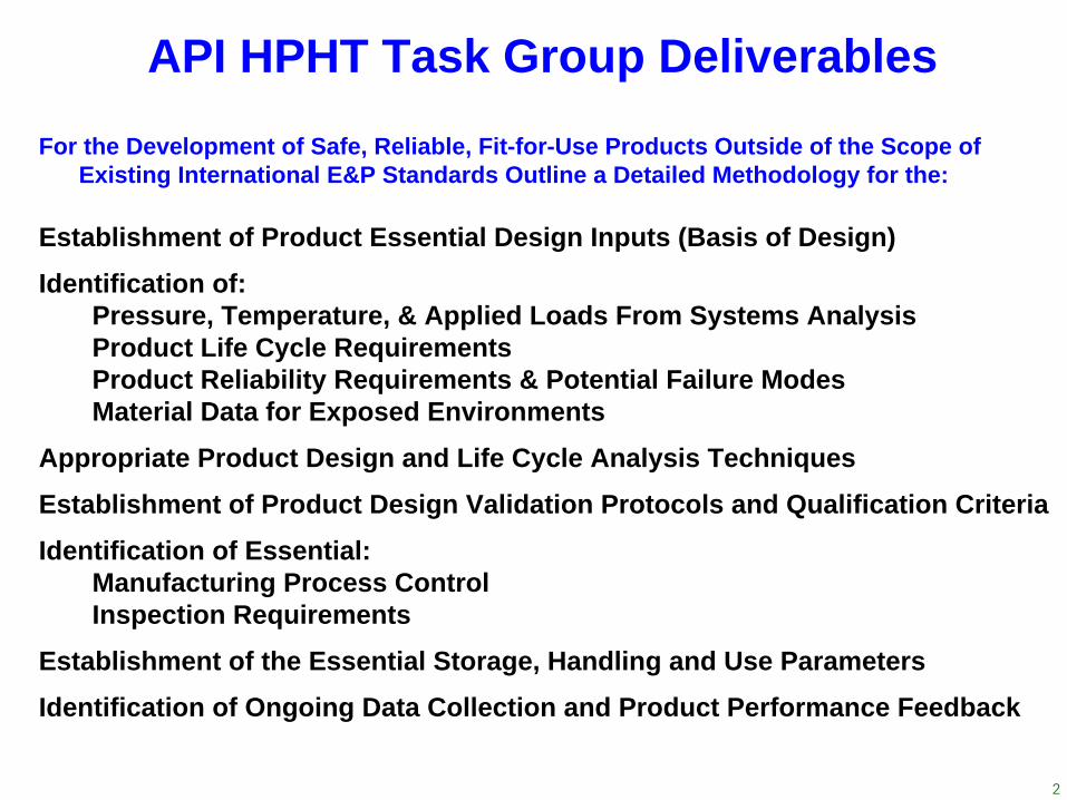
For the Development of Safe, Reliable, Fit-for-Use Products Outside of the Scope of Existing International E&P Standards Outline a Detailed Methodology for the:
Establishment of Product Essential Design Inputs (Basis of Design)
Identification of:Pressure, Temperature, & Applied Loads From Systems AnalysisProduct Life Cycle RequirementsProduct Reliability Requirements & Potential Failure Modes Material Data for Exposed Environments
Appropriate Product Design and Life Cycle Analysis Techniques
Establishment of Product Design Validation Protocols and Qualification Criteria
Identification of Essential:Manufacturing Process ControlInspection Requirements
Establishment of the Essential Storage, Handling and Use Parameters
Identification of Ongoing Data Collection and Product Performance Feedback
API HPHT Task Group Deliverables

3
Drivers for API to Perform this Work
New product technology without significant industry experience
High Pressure thick wall forged bodies have a different failure modewhich results in Fast Fracture as opposed to “Leak Before Burst”and requires different analysis techniques.
Challenging physical and environmental conditions of new E&Pdevelopments, beyond the limits of traditional industry standards.
Advanced design and analysis capabilities.
Industry commitment to the technical integrity and HSE associatedwith industry challenges.
Availability of significant historical experience and lessons-learned:1980’s: 30,000 psi wellhead and Xmas tree equipment1990’s: 300+ deg. F wellhead and Xmas tree equipment2000’s: Advanced design analysis capabilities and design codes

4
Product Development Process ForExisting or New Design Equipment
Fit for Purpose Qualification Process
Both LegsMust Be Performed
Basis of Design
Design Equipment &
Documentation
Design Meets FDS
Design Verification
Design Validation
Production
No
Yes
Functional Design
Specification

5
API Design Verification
DevelopmentProcess
Basis of Design
Design Equipment &
Documentation
Design Meets FDS
Design Verification
Design Validation
Production
Functional Design
Specification

6
API Design Validation
DevelopmentProcess
Basis of Design
Design Equipment &
Documentation
Design Meets FDS
Design Verification
Design Validation
Production
Functional Design
Specification

7
Project Basis of DesignOperational Specific Basis of Design
Equipment Location – Surface or SubseaLocation Environment – Max / MinPressure – Inside / Outside
Maximum / Minimum / Transient / Steady StateVarious Flow Rates
Temperature – Inside / OutsideMaximum / Minimum / Transient / Steady StateVarious Flow Rates
Environmental ExposureOutside (seawater, drilling and completion fluids, etc)Inside (seawater, drilling and completion fluids, etc)Reservoir Surfaces ContactReservoir Chemistry
Anticipated Life Cycle Operating RequirementsInterventions, Work Over, Shutdowns, etc.
DevelopmentProcess
Basis of Design
Design Equipment &
Documentation
Design Meets FDS
Design Verification
Design Validation
Production
Functional Design
Specification
8
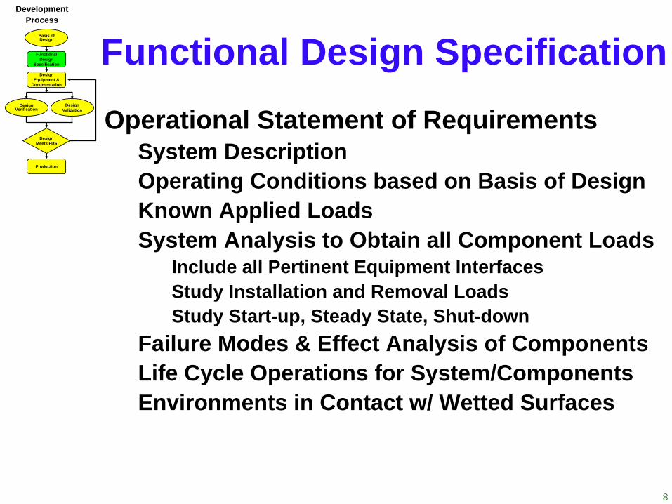
Functional Design SpecificationOperational Statement of Requirements
System DescriptionOperating Conditions based on Basis of DesignKnown Applied LoadsSystem Analysis to Obtain all Component Loads
Include all Pertinent Equipment InterfacesStudy Installation and Removal LoadsStudy Start-up, Steady State, Shut-down
Failure Modes & Effect Analysis of ComponentsLife Cycle Operations for System/ComponentsEnvironments in Contact w/ Wetted Surfaces
DevelopmentProcess
Basis of Design
Design Equipment &
Documentation
Design Meets FDS
Design Verification
Design Validation
Production
Functional Design
Specification

BOP or SS Tree
System AnalysisSpecification Breaks
AboveWellhead
WellheadCasingTubing
CompletionEquipment
DevelopmentProcess
Basis of Design
Design Equipment &
Documentation
Design Meets FDS
Design Verification
Design Validation
Production
Functional Design
Specification

10
C/K Manifold & Rig Piping
C/K Lines & Flex Pipe
C/K Valves & Piping
Ram BOP’s & Wellhead Connector
Wellhead
System AnalysisSpecification Breaks
Well ConstructionWell CompletionWell Intervention
Surface
Riser
BOP & Wellhead
DevelopmentProcess
Basis of Design
Design Equipment &
Documentation
Design Meets FDS
Design Verification
Design Validation
Production
Functional Design
Specification

11
Design & Documentation
Design Specifications and PracticesApplicable Industry StandardsCustomer SpecificationsCompany Proprietary IP
Determine Design Envelope & Interface DimensionsDetermine Physical Operating EnvelopeFunctional Issues (outlets, door openings, etc.)Material / Welding SpecificationsNDE CriteriaSpecify Design Verification Analysis RequirementsSpecify Design Validation Testing RequirementsWrite Design Verification & Validation Quality Plans
DevelopmentProcess
Basis of Design
Design Equipment &
Documentation
Design Meets FDS
Design Verification
Design Validation
Production
Functional Design
Specification

12
Design VerificationUses Functional Specification as Inputs
Design Material PropertiesMaterial Properties At Design Temperature (Inside & Out)Material Properties In Service Environment (Inside & Out)Determine Minimum Detectable Flaw Size (inspection)
Comprehensive Design Conditions AnalysesStatic, Dynamic, & Transient Pressure (Inside and Out)Thermal (Inside and Out)Loads (Tension, Bending, & Torsion)
Stress Analysis Using FEAComprehensive Design Conditions (Operating)Hydrostatic Proof Test
Life Cycle Fatigue AnalysisFracture Mechanics/S-N CurvesCycles to Failure
DevelopmentProcess
Basis of Design
Design Equipment &
Documentation
Design Meets FDS
Design Verification
Design Validation
Production
Functional Design
Specification
13
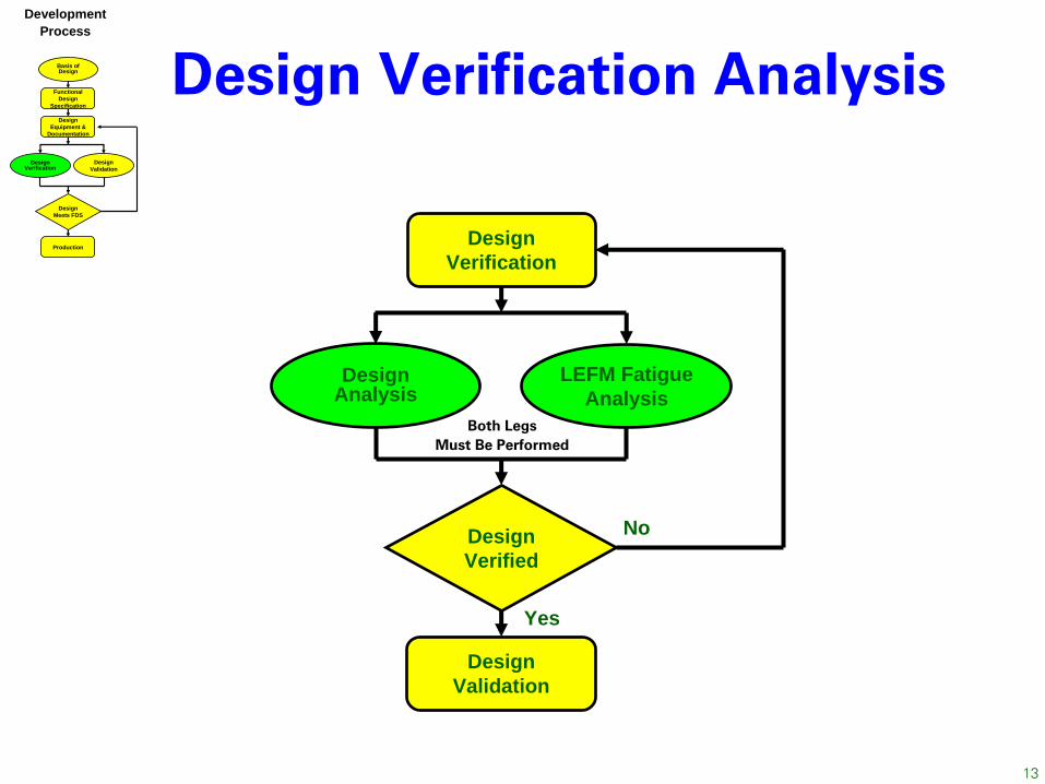
Design Verification Analysis
Both LegsMust Be Performed
DesignVerification
DesignVerified
DesignAnalysis
LEFM Fatigue Analysis
DesignValidation
No
Yes
DevelopmentProcess
Basis of Design
Design Equipment &
Documentation
Design Meets FDS
Design Verification
Design Validation
Production
Functional Design
Specification

14
Design Verification Analysis •
Applies to pressure containing parts •
Does not apply to pressure retaining parts•
Does not apply to closure bolting •
Does not apply to ring gaskets
Design Analysis
Design Analysis
Plastic Collapse Analysis
ASME VIII-2 Par 5.2.4
Local Strain Limit Analysis
ASME VIII-2 Par 5.3.3
Ratcheting Analysis ASME VIII-2 Par 5.5.7
LEFM Fatigue AnalysisASME VIII-3 KD-4
Leak Before Burst
S-N Fatigue AnalysisASME VIII-3 KD-3
No
Yes
DesignVerification
Both LegsMust Be Performed
DesignVerificatio
n
DesignVerified
DesignAnalysis
LEFM Fatigue
Analysis
DesignValidation
N o
Yes

15
LEFM Fatigue Analysis
Calculate crack growth for service life requirements
LEFM Fatigue Analysis
Initial crack size based upon NDE or incremental
crack size
Calculate stress intensity factor based upon crack
depth, a
New crack size <
allowable
No
Yes
Design meets spec
Redesign
No
( )[ ] ( )mKKRfCdNda
Δ⋅⋅=
•
Analysis required for each critical section
•
Assume initial crack size based upon NDE capability
•
Crack aspect ratio should be updated as crack grows
•
Use appropriate material crack growth rate data for environment and loading
•
Allowable crack size based upon ASME Div 3 KD-412 or Other Acceptable Criteria
DesignVerification
Both LegsMust Be Performed
DesignVerificatio
n
DesignVerified
DesignAnalysis
LEFM Fatigue
Analysis
DesignValidation
N o
Yes

16
Design Test ProgramUse Functional Design SpecificationsValidate Design VerificationInsitu Temperature Requirements
Inside and OutsideDynamic, Transient, and Steady-State
In-Service Load ConditionsPressure & All Applied Loads (Tension, Bending, Etc)Inside and OutsideDynamic, Transient, and Steady-State
Measure and Monitor Peak StressesEstablish Reliability Goals and Testing Methodology
If Physical Tests are ImpracticalAnalytical SimulationsScale Model TestsTests of Less Magnitude - Scale
Design ValidationBasis of Design
Design Equipment &
Documentation
Design Meets FDS
Design Verification
Design Validation
Production
Functional Design
Specification

17
•
FMEA, Failure Mode and Effects Analysis is a bottoms up approach to analyzing system design and performance. FMEAs employ probability of failure categories based on probability ranges.
•
FMECA, Failure Mode, Effects and Criticality Analysis is based on MIL-STD-1629, "Procedures for Performing a Failure Mode, Effects and Criticality Analysis". In a FMECA, the probability of a specific failure occurring is given as a numerical prediction.
•
A FMEA is qualitative, whereas a FMECA is a quantitative analysis. The proper category is determined by the experience and expertise of the analyst, instead of a mathematical probability calculation involving actual component failure rates.
Design Validation protocol development Using FMEA
(Failure Mode and Effects Analysis)
Basis of Design
Design Equipment &
Documentation
Design Meets FDS
Design Verification
Design Validation
Production
Functional Design
Specification

18
Design Meets Functional DesignSpecification (FDS)
Both Legs of Process Flowchart Must be SatisfiedThe Design Validation Process Confirms the Design Verification Results
Document All Design, Verification & Validation DataDesign Specifications and Practices
Applicable Industry StandardsCustomer SpecificationsCompany Proprietary IP
Material / Welding SpecificationsNDE CriteriaDesign Verification AnalysisDesign Validation TestingQuality Plans
DevelopmentProcess
Basis of Design
Design Equipment &
Documentation
Design Meets FDS
Design Verification
Design Validation
Production
Functional Design
Specification

19
APIRECOMMENDED
PRACTICE
Re-certifyRepair
DesignValidation
UseDocumentation
DesignVerification
FunctionalSpecification
FAT
Inspection
QA/QC
Materials
PurchaseSpecs
Manufacture
DesignBasis
Elements Required to CompleteThe Manufacturing Process
Product / Manufacturing
Elements
Design / PrototypeElements
DevelopmentProcess
Basis of Design
Design Equipment &
Documentation
Design Meets FDS
Design Verification
Design Validation
Production
Functional Design
Specification

20
Proposed Timeline for PER15KDevelopment
Process
Basis of Design
Design Equipment &
Documentation
Design Meets FDS
Design Verification
Design Validation
Production
Functional Design
Specification
Protocol for Equipment Rated Greater
than 15 ksi
Jim Raney/ Earl Shanks
Material’s Task Group
Jim Burk
Design & Development Verification
Earl Shanks
Design & Development
Validation
KhedherMellah
Protocol for Equipment Rated Greater
than 15 ksi
Jim Raney/ Earl Shanks
Material’s Task Group
Jim Burk
Design & Development Verification
Earl Shanks
Design & Development
Validation
KhedherMellah
PER15K
PER15K form as a task group under the ESC.Proposed Time Line for PER15K
Task DatesJan '09
Feb '09
Mar '09
Apr '09
May '09
Jun '09
Jul '09
Aug '09
Sept '09
Oct '09
Nov '09
Dec '09
Jan '10
Presentation at the API Winter Meeting Jan ‘09.Set meeting with vendors and operators Jan-June ‘09Hold quarterly meeting to generate a draft document Jan-Sept ’09.1st Draft, Review draft. Oct ’09. 2nd Draft, Present at Winter API Meeting Jan’10.

21
Materials Deliverables and Timeline
•
Re-initiate Materials Task Group monthly meetings February 2009
•
Establish lists of Materials and Property Requirements-June 2009−
Elastic properties-Modulus & Poisson's ratio with temperature−
Mechanical strength –yield and ultimate with temperature−
Fracture Toughness –
CVN, KIC/JIC with temperature−
Fatigue –
S/N and crack Growth rate−
Environments –
Air & Seawater
•
Populate materials property tables –
October 2009
•
Establish additional data requirements –
December 2009
•
Propose testing (MMS F22 effort) –
2010 API Winter Meeting
DevelopmentProcess
Basis of Design
Design Equipment &
Documentation
Design Meets FDS
Design Verification
Design Validation
Production
Functional Design
Specification

22
Verification Development & Timeline
DevelopmentProcess
Basis of Design
Design Equipment &
Documentation
Design Meets FDS
Design Verification
Design Validation
Production
Functional Design
Specification
Example Analysis Required by ECS CompleteRecommendations Have Been Received to Modify DocFormed a Design Analysis Team
Review Recommended ChangesMake Recommendations to Verification Work Group - March
Verification Work Group Will Act on Recommendations - AprilRevise Verification Document - JuneEstablish Review Groups to Wordsmith Document - AugustMerge Work Efforts into New Revision - OctSubmit to PER15K Task Group - Nov

23
Validation Development Process•
Develop the test development protocol and use the 6HP example to
demonstrate it. Develop the process.
•
Perform the FMEA to come up with the test protocol for the completion equipment in question. Update the process.
•
Produce a document with proposed test protocol list and test steps.•
Collect feedback and update the document •
2009: Perform FMEA for:−
Ask participant to share FMEA and test example.−
SCSSV−
If time allows: Gauges or Packer
Basis of Design
Design Equipment &
Documentation
Design Meets FDS
Design Verification
Design Validation
Production
Functional Design
Specification
Proposed 2009 timeline
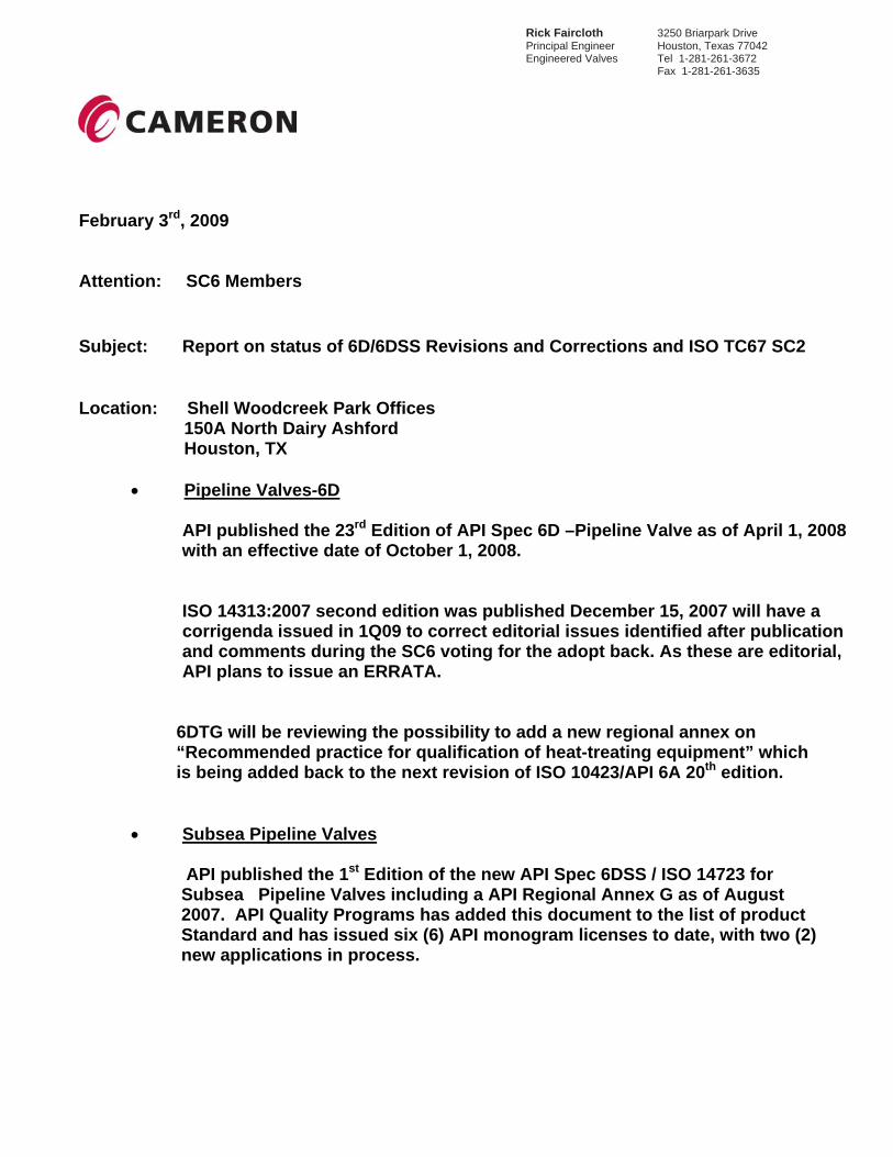
Rick Faircloth 3250 Briarpark Drive Principal Engineer Houston, Texas 77042 Engineered Valves Tel 1-281-261-3672 Fax 1-281-261-3635
February 3rd, 2009 Attention: SC6 Members Subject: Report on status of 6D/6DSS Revisions and Corrections and ISO TC67 SC2 Location: Shell Woodcreek Park Offices
150A North Dairy Ashford Houston, TX
• Pipeline Valves-6D
API published the 23rd Edition of API Spec 6D –Pipeline Valve as of April 1, 2008 with an effective date of October 1, 2008.
ISO 14313:2007 second edition was published December 15, 2007 will have a corrigenda issued in 1Q09 to correct editorial issues identified after publication and comments during the SC6 voting for the adopt back. As these are editorial, API plans to issue an ERRATA.
6DTG will be reviewing the possibility to add a new regional annex on “Recommended practice for qualification of heat-treating equipment” which is being added back to the next revision of ISO 10423/API 6A 20th edition.
• Subsea Pipeline Valves API published the 1st Edition of the new API Spec 6DSS / ISO 14723 for Subsea Pipeline Valves including a API Regional Annex G as of August 2007. API Quality Programs has added this document to the list of product Standard and has issued six (6) API monogram licenses to date, with two (2) new applications in process.

Rick Faircloth 3250 Briarpark Drive Principal Engineer Houston, Texas 77042 Engineered Valves Tel 1-281-261-3672 Fax 1-281-261-3635
• ISO TC67 SC2 Pipeline Transportation Systems ISO TC67 SC2 WG9 (ISO 14723 Subea Pipeline Valves) has completed its DIS voting and review by TC67 SC2 EDC. The FDIS is planned for voting in 1Q09. After the required 2 months voting period, the 2nd Edition of ISO 14723 should be published by ISO in end of 2Q09 or early 3Q09. Upon publication 6D TG plan to conduct a review of the standard and make a recommendation to SC6 to vote on the adopt back as the 2nd Edition of API6DSS. Respectfully submitted,
Rick Faircloth Chairman- 6D/6DSS TG on Revisions and Corrections and Convener-ISO TC67 SC2 WG2 and WG9

Attachment 6
From: [email protected]
Sent: Sunday, February 01, 2009 2:09 PM
To: Edmund Baniak
Cc: Patricia Reddington; Henry R. Sonderegger
Subject: draft iso 7268
Sir;
Your email arrived a day before closing of the ISO ballot for revision
and updating of document ISO 7268. There was not sufficient time to
convene a meeting of the USTAG to address your concerns.
Ms. Patricia Reddington, the Secretariat for ISO/TC 5/SC 10 and its
ASME/US-TAG conferred consideration of an explanation to me. I am the
Chair for the ISO/TC 5/SC 10 committee charged with the content of the
draft ISO 7268 and I also Chair the US-TAG for this item, therefore I
have some familiarity of its status. With reference to your commentary, I
offer the following observations in the hope that they may be of value in
your future consideration of this draft standard.
1. As a starting point, note that this revision simply elaborates the
previous edition of ISO 7268 that dates back to a 1983 issue date and
that only dealt with a definition for PN. Since this issue date, the ISO
concept of market relevance has been introduced and this has signaled a
need to recognize that the USA Class designation is by far the most
referenced such designation with the balance split between the European
PN and the Japanese K.
2. Fundamentally, ISO 7268 draft provides guidance in the
selection of designators to be used in ISO standards, leaving it to the
component standard writer to choose PN, Class or K with the listed non-
dimensional numbers cited as appropriate for their need. The first para.
of the draft Scope notes that “ as specified in … component standards”
The second paragraph notes designation numeric’s that are appropriate
for the alpha part of the designator.
3 The definition for PN is basically unchanged from the current
edition. The numeric designators are those listed in ISO 7005-1 dating
back to 1992 for European usage and are current in the European Standard
EN 1092-1. Note the absence of a PN 20 as well as the absence of any
other so called Class related PN's in EN 1092-1.

Attachment 6
4. The number following PN is dimensionless and has no relation to a
specific pressure value. It is described as so in the publication ISO
7268 : 1983, obviously not a new concept.
5. In EN 1092-1, it is true that most of the pressure ratings for ?10oC
= T = 50oC correspond to the PN dimensionless number, however, it is not
always true. For example Table 17, PN 100 has RT values of 84.4 bar, a
19% variation.
6. The TC 5/SC 10 committee has, over the course of many years asked for
the calculation basis for determining the PN pressure/temperature values.
These have been promised but have never been produced. The Class rating
basis is detailed in ASME B16.5 and in ASME B16.34.
7. A very important aspect in attempting to have a proper relationship
between PN and Class designations has to do with the wide variations that
exist at temperatures above 50oC. For example, PN20 (interpolated Table
17, EN 1092-1) at 400oC would have an allowable pressure up to 10.4 bar
whereas ASME B16.5, Class 150, Table 2-1.1 shows a maximum rating of 6.5
bar; a 40% variation. This clearly demonstrates that there is a need to
avoid representing a PN number as an acceptable alternative to Class
number.
8. The cross referencing of PN to Class that you identify was initiated
in the 1972 edition of ISO 7005-1. This somewhat arbitrary contrivance
was an attempt to displace the Class designation system used by ASME
Standards. (Note in ISO 7005-1 that Class 600 is shown as PN 110 so as to
not confuse it with (in 1992) a DIN flange designation.)
9. Your PN 100 example covers only one listing. Note that
B16.5 CWP ratings for Class 600 cover a range of 33.1 = CWP = 103.4 bar.
That is, in the Class system the CWP is not a constant value but varies
with component material mechanical properties.
10. In regards the size designation DN, early on the European standard
experts submitted DN, diamиtre nominale, for ISO as an
acknowledgment to their French members to replace the previously used ND,
nominal diameter. Note that DN and NPS have a correspondence, see B16.5-
2003, para. 1.9.

Attachment 6
11. The number that follows NPS is indeed dimensionless and is used as
described in the draft. For example, a pipe designated as NPS 6 is
without any characteristic having a dimension of 6-inches. In order to
determine the dimensions of a pipe one needs both an NPS number and a
pipe schedule number.
12. Drawing the distinction between K for size and Kv for flow is the
responsibility of the standards writer should the need arise for both to
be used in the same standard.
13. In summary,
a. The draft ISO 7268 does correctly define pressure designations as
used in relevant market sectors.
b. The draft does not change the substance of the
definition of PN from the definition of that in the current edition ISO
7268. The draft does introduce a proper definition for the Class
designation. Note that work is in progress with a draft FDIS 7005-1 that
will eliminate the PN numbers that were subjectively assigned to Class
numbers pre 1992. The ISO standards (and ASME standards) that use these
now outdated PN numbers will have to be edited.
Your concern is very much appreciated. You can be assured that the USTAG
is doing all it can to accommodate present day market place needs of the
USTAG members some of whom currently participate in API upstream
standards writing.
Sincerely,
BiLL McLean

Attachment 7
Presented by John H. Fowler to the API SC6 winter meeting, February 3, 2009
Revisions to API 6A to accommodate the 2007 ASME Code Section VIII Division 2
Progress to date: 1. Proposed changes were presented at the summer 2008 Standardization Conference. Fowler tasked to present
final recommendations at the winter 2009 meeting.
2. Several active stress-wise engineers from several companies were sent e-mail copies of those
recommendations and asked to comment.
3. A number of issues were brought up which will require further investigation:
a. How to specify the QC required for each method (classical vs. new ASME)?
b. How to handle the other non-standard material allowable stresses if membrane stress is allowed to go
to 0.9 Sy at test pressure?
c. Should we include the classical ASME method as an annex to 6A since ASME no longer permits it?
d. Should we further clarify the design methods including when to use stress intensity vs. equivalent stress
in which methods?
4. Meanwhile SC16 requested Fowler to recommend similar changes to Specs 16A and 16C, which differ from 6A.
It would be a good opportunity to harmonize the requirements of these three specifications.
Recommendation: Enlist the assistance of engineers who perform or review design verification calculations of 16A, 16C and 17D
equipment to join the task group and recommend common design requirements for the three specifications.
Since 17D refers to 6A for design requirements, by revising 6A, 16A and 16C we cover 17D as well.

API SUBCOMMITTEE 6WORK GROUP ON API SPEC 6A718
3 February 2009Tim Haeberle – Work Group ChairmanHouston, Texas
Attachment 8
2
6A718 Work Group Objectives
• API Spec 6A718 1st Edition was issued in March of 2004
• API policy requires specifications be reviewed every 5 years
• The options are as follows:
• Reaffirm as is
• Revise and re-release
• Withdraw if no longer needed

3
Work Group membership
Allvac
Baker Hughes
BP
Cameron
Cartech
Chevron
CRA Alloys
ExxonMobil
FMCTI
Foroni
GE Oil & Gas – VetcoGray
Halliburton
Howco
Latrobe Steel
Shell
Schlumberger
Special Quality Alloys
ThyssenKrupp VDM
Tube Supply
Wood Group
4
First WG Meeting – 2 December 2008
• 21 Attendees
• Decision made to revise and re-release API Spec 6A718
• 15 proposed revisions presented

5
Second Meeting – 2 February 2009
• 23 attendees
• Revision status:
• 6 revisions approved
• 7 revisions rejected
• 2 revisions tabled, pending further input
6
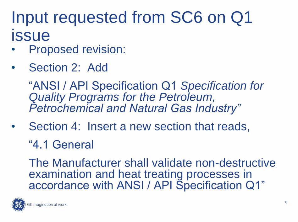
Input requested from SC6 on Q1 issue• Proposed revision:
• Section 2: Add
―ANSI / API Specification Q1 Specification for Quality Programs for the Petroleum, Petrochemical and Natural Gas Industry”
• Section 4: Insert a new section that reads,
―4.1 General
The Manufacturer shall validate non-destructive examination and heat treating processes in accordance with ANSI / API Specification Q1‖

7
Justification
It was stated that this is required by API Q1 clause 7.5.2.1 (see below) and needs to be addressed in the product standards according to API ECS meeting minutes (January 21, 2008, Ft. Worth, Texas).
API Specification Q1, Eighth Edition (Effective Date: June 15, 2008):
―7.5.2.1 Validation of processes for production and service provision — Supplemental
The organization shall validate those processes identified by the applicable product specification as requiring validation. If these processes are not identified, or there is no product specification involved, the processes requiring validation shall include, as a minimum, non-destructive examination, welding and heat treating, if applicable to the product.‖

8
Input requested from SC6
•Is this really required for API Spec 6A718?
•What does ―validation‖ mean?
9
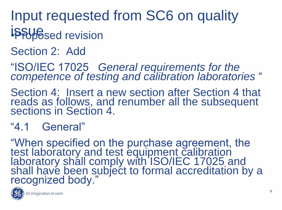
Input requested from SC6 on quality issue•Proposed revision
Section 2: Add
―ISO/IEC 17025 General requirements for the competence of testing and calibration laboratories ―
Section 4: Insert a new section after Section 4 that reads as follows, and renumber all the subsequent sections in Section 4.
―4.1 General‖
―When specified on the purchase agreement, the test laboratory and test equipment calibration laboratory shall comply with ISO/IEC 17025 and shall have been subject to formal accreditation by a recognized body.‖

10
Justification
This will add test laboratory and equipment calibration laboratory requirements that are not addressed by API Q1 / ISO 9001.

11
Input requested from SC6
•Should this be in a quality system spec?
•Should this be in another spec such as API Spec 6A, the parent to API Spec 6A718?
•Should specs contain statements such as, ―When
specified on the purchase agreement,…‖
12
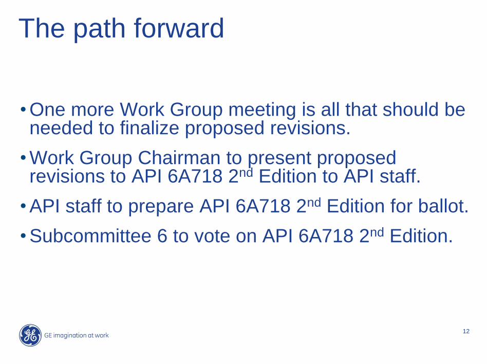
The path forward
• One more Work Group meeting is all that should be needed to finalize proposed revisions.
• Work Group Chairman to present proposed revisions to API 6A718 2nd Edition to API staff.
• API staff to prepare API 6A718 2nd Edition for ballot.
• Subcommittee 6 to vote on API 6A718 2nd Edition.
13
End of presentation on
API SC6 Work Group on API Spec 6A718

Attachment 9
ISO WG3 Meeting October 20-21, 2008
Attending:
Eric Wehner - Cameron
Maxwell Cerqueira - Petrobras
Richard Preston - FMC
Joel Russo - FMC
David Zollo - FMC
Scott Higgins - BP
Jean Brunjes – Vetco Gray
Jerry Janszen – original 10423 Convenor
Dag Ketil Freidheim -StatoilHydro
Maarten Kuipers - Mokveld
David Cole - Shell
Austin Freeman - Halliburton
Ries Langereis – Cameron ISO 10423
Convenor
Alfred Kruijer – Shell Secretary
Opening Remarks:
The meeting was called to order, hotel safety instructions for evacuation reviewed and the
attendees welcomed. The purposes of the meeting were outlined as following:
Purposes:
1. Action comments from DIS circulation of ISO 10423.
2. Discuss further differences remaining between ISO 10423 and API Spec 6A.
The possibilities for how to action comments in ISO were reviewed. These were stated
as:
• Accepted: – Text revised identically to the comment.
• Accepted in principle: – State what text changes are required to make the comment acceptable to the work group.
• Rejected: – State why the comment was rejected.
• Noted: – Normally used when no specific action is proposed. Explanation of why a comment was
“noted” is not required.
– Used when scope of change is so significant requiring significant textual changes to
incorporate and may be deferred to the next revision.
The review of comments commenced. On the first day, approximately 20 pages were
completed. On the second day the remaining 13 pages were completed. All of the action
items related to actually making the changes to the document using the ISO template
would be completed by Alfred Kruijer. Other action items by various members of
workgroup are captured below.
Action Items:
1. If desired, Petrobras is suggested to develop proposal to API and/or ISO for the
development of life-cycle performance validation methods under actual/adverse
production environment conditions to supplement existing text in Annex F.
Attachment 9
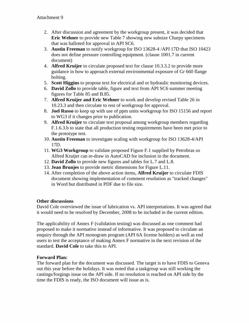
2. After discussion and agreement by the workgroup present, it was decided that
Eric Wehner to provide new Table 7 showing new subsize Charpy specimens
that was balloted for approval in API SC6.
3. Austin Freeman to notify workgroup for ISO 13628-4 /API 17D that ISO 10423
does not define pressure controlling equipment. (clause 1001.7 in current
document)
4. Alfred Kruijer to circulate proposed text for clause 10.3.3.2 to provide more
guidance in how to approach external environmental exposure of Gr 660 flange
bolting.
5. Scott Higgins to propose text for electrical and or hydraulic monitoring devices.
6. David Zollo to provide table, figure and text from API SC6 summer meeting
figures for Table 85 and B.85.
7. Alfred Kruijer and Eric Wehner to work and develop revised Table 26 in
10.23.3 and then circulate to rest of workgroup for approval.
8. Joel Russo to keep up with use of ppm units workgroup for ISO 15156 and report
to WG3 if it changes prior to publication.
9. Alfred Kruijer to circulate text proposal among workgroup members regarding
F.1.6.3.b to state that all production testing requirements have been met prior to
the prototype test.
10. Austin Freeman to investigate scaling with workgroup for ISO 13628-4/API
17D.
11. WG3 Workgroup to validate proposed Figure F.1 supplied by Petrobras so
Alfred Kruijer can re-draw in AutoCAD for inclusion in the document.
12. David Zollo to provide new figures and tables for L.7 and L.8.
13. Jean Brunjes to provide metric dimensions for Figure L.11.
14. After completion of the above action items, Alfred Kruijer to circulate FDIS
document showing implementation of comment resolution as "tracked changes"
in Word but distributed in PDF due to file size.
Other discussions
David Cole overviewed the issue of lubrication vs. API interpretations. It was agreed that
it would need to be resolved by December, 2008 to be included in the current edition.
The applicability of Annex F (validation testing) was discussed as one comment had
proposed to make it normative instead of informative. It was proposed to circulate an
enquiry through the API monogram program (API 6A license holders) as well as end
users to test the acceptance of making Annex F normative in the next revision of the
standard. David Cole to take this to API.
Forward Plan:
The forward plan for the document was discussed. The target is to have FDIS to Geneva
out this year before the holidays. It was noted that a taskgroup was still working the
castings/forgings issue on the API side. If no resolution is reached on API side by the
time the FDIS is ready, the ISO document will issue as is.