api specification 5ct eighth edition, july 1, 2005 iso ... · api standards department telephone...
TRANSCRIPT
Specification for Casing and Tubing API Specification 5CT Eighth Edition, July 1, 2005 ISO 11960:2004, Petroleum and natural gas industries—Steel pipes for use as casing or tubing for wells EFFECTIVE DATE: JANUARY 1, 2006
Copyright American Petroleum Institute Reproduced by IHS under license with API No reproduction or networking permitted without license from IHS
Not for Resale
--`,,,```-`-`,,`,,`,`,,`---

Copyright American Petroleum Institute Reproduced by IHS under license with API
Not for ResaleNo reproduction or networking permitted without license from IHS
--`,,,```-`-`,,`,,`,`,,`---
Special Notes API publications necessarily address problems of a general nature. With respect to particular circumstances, local, state, and federal laws and regulations should be reviewed.
API is not undertaking to meet the duties of employers, manufacturers, or suppliers to warn and properly train and equip their employees, and others exposed, concerning health and safety risks and precautions, nor undertaking their obligations under local, state, or federal laws.
Information concerning safety and health risks and proper precautions with respect to particular materials and conditions should be obtained from the employer, the manufacturer or supplier of that material, or the material safety data sheet.
Nothing contained in any API publication is to be construed as granting any right, by implication or otherwise, for the manufacture, sale, or use of any method, apparatus, or product covered by letters patent. Neither should anything contained in the publication be construed as insuring anyone against liability for infringement of letters patent.
Generally, API standards are reviewed and revised, reaffirmed, or withdrawn at least every five years. Sometimes a one-time extension of up to two years will be added to this review cycle. This publication will no longer be in effect five years after its publication date as an operative API standard or, where an extension has been granted, upon republication. Status of the publication can be ascertained from the API Standards department telephone (202) 682-8000. A catalog of API publications, programs and services is published annually and updated biannually by API, and available through Global Engineering Documents, 15 Inverness Way East, M/S C303B, Englewood, CO 80112-5776.
This document was produced under API standardization procedures that ensure appropriate notification and participation in the developmental process and is designated as an API standard. Questions concerning the interpretation of the content of this standard or comments and questions concerning the procedures under which this standard was developed should be directed in writing to the Director of the Standards department, American Petroleum Institute, 1220 L Street, N.W., Washington, D.C. 20005. Requests for permission to reproduce or translate all or any part of the material published herein should be addressed to the Director, Business Services.
API standards are published to facilitate the broad availability of proven, sound engineering and operating practices. These standards are not intended to obviate the need for applying sound engineering judgment regarding when and where these standards should be utilized. The formulation and publication of API standards is not intended in any way to inhibit anyone from using any other practices.
Any manufacturer marking equipment or materials in conformance with the marking requirements of an API standard is solely responsible for complying with all the applicable requirements of that standard. API does not represent, warrant, or guarantee that such products do in fact conform to the applicable API standard.
All rights reserved. No part of this work may be reproduced, stored in a retrieval system, or
transmitted by any means, electronic, mechanical, photocopying, recording, or otherwise, without prior written permission from the publisher. Contact the Publisher, API Publishing Services, 1220 L
Street, N.W., Washington, D.C. 20005.
Copyright © 2005 American Petroleum Institute
Copyright American Petroleum Institute Reproduced by IHS under license with API
Not for ResaleNo reproduction or networking permitted without license from IHS
--`,,,```-`-`,,`,,`,`,,`---
API Foreword
This standard is under the jurisdiction of the API Standards Subcommittee on Tubular Goods (API C1/SC5). This API standard is identical with the English version of ISO 11960:2004. ISO 11960 was prepared by Technical Committee ISO/TC 67, Materials, equipment and offshore structures for petroleum and natural gas industries, SC 5, Casing, Tubing, and Drilling Pipe.
This standard shall become effective on the date printed on the cover but may be used voluntarily from the date of publication.
The bar notations in the margins identify parts of this standard that have been changed from the previous API edition. While efforts have been made to ensure the accuracy of the notations, the user of this standard is responsible for recognizing any differences between this and the previous edition.
API publications may be used by anyone desiring to do so. Every effort has been made by the Institute to assure the accuracy and reliability of the data contained in them; however, the Institute makes no representation, warranty, or guarantee in connection with this publication and hereby expressly disclaims any liability or responsibility for loss or damage resulting from its use or for the violation of any federal, state, or municipal regulation with which this publication may conflict.
Suggested revisions are invited and should be submitted to API, Standards department, 1220 L Street, NW, Washington, DC 20005, [email protected].
Copyright American Petroleum Institute Reproduced by IHS under license with API
Not for ResaleNo reproduction or networking permitted without license from IHS
--`,,,```-`-`,,`,,`,`,,`---
Contents Page API Foreword .......................................................................................................................................................... ii Foreword ................................................................................................................................................................ vi Introduction ........................................................................................................................................................... vii 1 Scope ........................................................................................................................................................... 1 2 Conformance .............................................................................................................................................. 2 2.1 Normative references ................................................................................................................................ 2 2.2 Units of measurement ............................................................................................................................... 2 3 Normative references ................................................................................................................................ 2 4 Terms, definitions, symbols and abbreviated terms ............................................................................. 4 4.1 Terms and definitions ............................................................................................................................... 4 4.2 Symbols and abbreviated terms .............................................................................................................. 8 5 Information to be supplied by the purchaser ......................................................................................... 9 5.1 Casing ......................................................................................................................................................... 9 5.2 Tubing ....................................................................................................................................................... 11 5.3 Coupling stock and accessories ............................................................................................................ 12 6 Process of manufacture .......................................................................................................................... 12 6.1 General ..................................................................................................................................................... 12 6.2 Heat treatment .......................................................................................................................................... 13 6.3 Straightening ............................................................................................................................................ 13 6.4 Traceability ............................................................................................................................................... 14 6.5 Processes requiring validation .............................................................................................................. 15 7 Material requirements ............................................................................................................................. 15 7.1 Chemical composition ............................................................................................................................ 15 7.2 Tensile properties .................................................................................................................................... 15 7.3 Charpy V-notch test — General requirements ..................................................................................... 16 7.4 Charpy V-notch test — Absorbed energy requirements for coupling stock, coupling blanks and couplings .............................................................................................................................. 17 7.5 Charpy V-notch test — Absorbed energy requirements for pipe ....................................................... 18 7.6 Charpy V-notch test — Absorbed energy requirements for casing and tubing accessories ......... 20 7.7 Maximum hardness ................................................................................................................................. 21 7.8 Hardness variation — Grades C90, T95 and Q125 ............................................................................... 21 7.9 Process control — Grades C90, T95 and Q125 .................................................................................... 21 7.10 Hardenability — Minimum percentage martensite for quenched and tempered products .............. 21 7.11 Grain size — Grades C90 and T95 ......................................................................................................... 22 7.12 Surface condition — Grades L80 9Cr and L80 13Cr ............................................................................ 22 7.13 Flattening — Electric-welded pipe ......................................................................................................... 22 7.14 Sulfide stress cracking test — Grades C90 and T95 ........................................................................... 22 8 Dimensions, masses, tolerances, pipe ends and defects ................................................................... 24 8.1 Labels and sizes ...................................................................................................................................... 24 8.2 Dimensions and masses ......................................................................................................................... 24 8.3 Diameter ................................................................................................................................................... 24 8.4 Wall thickness .......................................................................................................................................... 25 8.5 Mass .......................................................................................................................................................... 25 8.6 Length ....................................................................................................................................................... 25 8.7 Casing jointers ......................................................................................................................................... 25 8.8 Height and trim of electric-weld flash ................................................................................................... 26 8.9 Straightness ............................................................................................................................................. 26 8.10 Drift requirements ................................................................................................................................... 27 8.11 Tolerances on dimensions and masses ............................................................................................... 27
API Specification 5CT / ISO 11960
iiiCopyright American Petroleum Institute Reproduced by IHS under license with API
Not for ResaleNo reproduction or networking permitted without license from IHS
--`,,,```-`-`,,`,,`,`,,`---
ISO 11960:2004(E)
iv © ISO 2004 – All rights reserved
8.12 Pipe ends..............................................................................................................................................28 8.13 Defects..................................................................................................................................................30 8.14 Coupling make-up and thread protection.........................................................................................30 9 Couplings .............................................................................................................................................31 9.1 General requirements .........................................................................................................................31 9.2 Alternative grades or heat treatments...............................................................................................31 9.3 Process of manufacture — Groups 1, 2 and 3 .................................................................................32 9.4 Process of manufacture — Grade Q125 ...........................................................................................32 9.5 Mechanical properties ........................................................................................................................32 9.6 Dimensions and tolerances................................................................................................................32 9.7 Regular couplings ...............................................................................................................................32 9.8 Special-clearance couplings — Groups 1, 2 and 3 ..........................................................................33 9.9 Combination couplings ......................................................................................................................33 9.10 Reducing couplings — Groups 1, 2 and 3 ........................................................................................33 9.11 Seal-ring couplings .............................................................................................................................33 9.12 Special-bevel tubing couplings — Groups 1, 2 and 3 .....................................................................33 9.13 Threading .............................................................................................................................................33 9.14 Surface inspection ..............................................................................................................................34 9.15 Measurement of imperfections ..........................................................................................................35 9.16 Repair and removal of imperfections and defects...........................................................................35 9.17 Thread surface treatment — Grade Q125 .........................................................................................35 9.18 Couplings and coupling blank protection — Grades C90, T95 and Q125 .....................................35 10 Inspection and testing ........................................................................................................................35 10.1 Test equipment ....................................................................................................................................35 10.2 Lot definition for testing of mechanical properties .........................................................................35 10.3 Testing of chemical composition ......................................................................................................36 10.4 Tensile tests.........................................................................................................................................37 10.5 Flattening test ......................................................................................................................................39 10.6 Hardness test.......................................................................................................................................40 10.7 Impact test............................................................................................................................................44 10.8 Grain size determination — Grades C90 and T95 ............................................................................46 10.9 Hardenability — Grades C90 and T95 ...............................................................................................46 10.10 Sulfide stress-cracking test — Grades C90 and T95 .......................................................................46 10.11 Metallographic evaluation — EW Grades P110 and Q125 ..............................................................46 10.12 Hydrostatic tests .................................................................................................................................46 10.13 Dimensional testing ............................................................................................................................48 10.14 Visual inspection .................................................................................................................................51 10.15 Non-destructive examination (NDE) ..................................................................................................51 11 Marking.................................................................................................................................................58 11.1 General .................................................................................................................................................58 11.2 Stamp marking requirements.............................................................................................................59 11.3 Stencil marking requirements............................................................................................................60 11.4 Colour identification............................................................................................................................60 11.5 Thread and end-finish marking — All groups ..................................................................................61 11.6 Pipe-threader marking requirements — All groups.........................................................................61 12 Coating and protection .......................................................................................................................62 12.1 Coatings — All groups........................................................................................................................62 12.2 Thread protectors................................................................................................................................62 13 Documents ...........................................................................................................................................63 13.1 Electronic media — All groups ..........................................................................................................63 13.2 Certification — Groups 1, 2 and 3......................................................................................................63 13.3 Certification requirements — Grade Q125........................................................................................63 13.4 Retention of records ...........................................................................................................................63 14 Minimum facility requirements for various categories of manufacturer .......................................64 14.1 Pipe mill ................................................................................................................................................64 14.2 Processor .............................................................................................................................................64 14.3 Pipe threader........................................................................................................................................64
API Specification 5CT / ISO 11960
ivCopyright American Petroleum Institute Reproduced by IHS under license with API
Not for ResaleNo reproduction or networking permitted without license from IHS
--`,,,```-`-`,,`,,`,`,,`---
ISO 11960:2004(E)
© ISO 2004 – All rights reserved v
14.4 Coupling, pup-joint or accessory manufacturer.............................................................................. 64 Annex A (normative) Supplementary requirements ..................................................................................... 66 Annex B (normative) Purchaser inspection................................................................................................... 80 Annex C (normative) Tables in SI units.......................................................................................................... 81 Annex D (normative) Figures in SI (USC) units ........................................................................................... 154 Annex E (normative) Tables in USC units.................................................................................................... 184 Annex F (informative) Marking instructions for API licensees .................................................................. 258 Annex G (informative) Procedures used to convert from USC units to SI units...................................... 263 Annex H (normative) Product Specification Levels .................................................................................... 276 Annex I (normative) Requirements for thread protector design validation ............................................. 283 Annex J (informative) Summary of Product Specification Level (PSL) requirements ............................ 287 Bibliography ................................................................................................................................................... 291
API Specification 5CT / ISO 11960
vCopyright American Petroleum Institute Reproduced by IHS under license with API
Not for ResaleNo reproduction or networking permitted without license from IHS
--`,,,```-`-`,,`,,`,`,,`---
ISO 11960:2004(E)
vi © ISO 2004 – All rights reserved
Foreword
ISO (the International Organization for Standardization) is a worldwide federation of national standards bodies (ISO member bodies). The work of preparing International Standards is normally carried out through ISO technical committees. Each member body interested in a subject for which a technical committee has been established has the right to be represented on that committee. International organizations, governmental and non-governmental, in liaison with ISO, also take part in the work. ISO collaborates closely with the International Electrotechnical Commission (IEC) on all matters of electrotechnical standardization.
International Standards are drafted in accordance with the rules given in the ISO/IEC Directives, Part 2.
The main task of technical committees is to prepare International Standards. Draft International Standards adopted by the technical committees are circulated to the member bodies for voting. Publication as an International Standard requires approval by at least 75 % of the member bodies casting a vote.
Attention is drawn to the possibility that some of the elements of this document may be the subject of patent rights. ISO shall not be held responsible for identifying any or all such patent rights.
ISO 11960 was prepared by Technical Committee ISO/TC 67, Materials, equipment and offshore structures for petroleum, petrochemical and natural gas industries, Subcommittee SC 5, Casing, tubing and drill pipe.
This third edition cancels and replaces the second edition (ISO 11960:2001), which has been technically revised. It also incorporates the Technical Corrigendum ISO 11960:2001/Cor.1:2002.
It is the intent of TC 67 that the second and third editions of ISO 11960 both be applicable, at the option of the purchaser (as defined in 4.1.35), for a period of six months from the first day of the calendar quarter immediately following the date of publication of this third edition, after which period the second edition will no longer be applicable.
API Specification 5CT / ISO 11960
viCopyright American Petroleum Institute Reproduced by IHS under license with API
Not for ResaleNo reproduction or networking permitted without license from IHS
--`,,,```-`-`,,`,,`,`,,`---
ISO 11960:2004(E)
© ISO 2004 – All rights reserved vii
Introduction
This International Standard is based on API 5CT (Specification for Casing and Tubing).
Users of this International Standard should be aware that further or differing requirements may be needed for individual applications. This International Standard is not intended to inhibit a vendor from offering, or the purchaser from accepting, alternative equipment or engineering solutions for the individual application. This may be particularly applicable where there is innovative or developing technology. Where an alternative is offered, the vendor should identify any variations from this International Standard and provide details.
This International Standard includes requirements of various nature. These are identified by the use of certain verbal forms:
SHALL is used to indicate that a provision is MANDATORY;
SHOULD is used to indicate that a provision is not mandatory, but RECOMMENDED as good practice;
MAY is used to indicate that a provision is OPTIONAL.
API Specification 5CT / ISO 11960
viiCopyright American Petroleum Institute Reproduced by IHS under license with API
Not for ResaleNo reproduction or networking permitted without license from IHS
--`,,,```-`-`,,`,,`,`,,`---

Copyright American Petroleum Institute Reproduced by IHS under license with API
Not for ResaleNo reproduction or networking permitted without license from IHS
--`,,,```-`-`,,`,,`,`,,`---
INTERNATIONAL STANDARD ISO 11960:2004(E)
© ISO 2004 – All rights reserved 1
Petroleum and natural gas industries — Steel pipes for use as casing or tubing for wells
1 Scope
1.1 This International Standard specifies the technical delivery conditions for steel pipes (casing, tubing, plain-end casing liners and pup joints), coupling stock and accessories and establishes requirements for three Product Specification Levels (PSL-1, PSL-2, PSL-3). The requirements for PSL-1 are the basis of this International Standard. The requirements that define different levels of standard technical requirements for PSL-2 and PSL-3, for all Grades except H-40 and L-80 9Cr, are contained in Annex H.
For pipes covered by this International Standard, the sizes, masses and wall thicknesses as well as grades and applicable end-finishes are listed in Tables C.1 to C.3 and Tables E.1 to E.3.
By agreement between the purchaser and manufacturer, this International Standard can also be applied to other plain-end pipe sizes and wall thicknesses.
This International Standard is applicable to the following connections in accordance with API Spec 5B:
short round thread casing (STC);
long round thread casing (LC);
buttress thread casing (BC);
extreme-line casing (XC);
non-upset tubing (NU);
external upset tubing (EU);
integral joint tubing (IJ).
For such connections, this International Standard specifies the technical delivery conditions for couplings and thread protection. Supplementary requirements that may optionally be agreed for enhanced leak resistance connections are given in Annex A.11 (SR22).
This International Standard can also be applied to tubulars with connections not covered by ISO/API standards.
1.2 The four groups of products to which this International Standard is applicable include the following grades of pipe:
Group 1: All casing and tubing in Grades H, J, K and N;
Group 2: All casing and tubing in Grades C, L, M and T;
Group 3: All casing and tubing in Grade P;
Group 4: All casing in Grade Q.
API Specification 5CT / ISO 11960
1Copyright American Petroleum Institute Reproduced by IHS under license with API
Not for ResaleNo reproduction or networking permitted without license from IHS
--`,,,```-`-`,,`,,`,`,,`---
ISO 11960:2004(E)
2 © ISO 2004 – All rights reserved
1.3 Casing sizes larger than Label 1: 4-1/2 but smaller than Label 1: 10-3/4 may be specified by the purchaser to be used in tubing service, see Tables C.1, C.24, C.30 and C.31 or Tables E.1, E.24, E.30 and E.31.
1.4 Supplementary requirements that may optionally be agreed between purchaser and manufacturer for non-destructive examination, coupling blanks, upset casing, electric-welded casing, impact testing, seal ring couplings and certificates are given in Annex A.
1.5 This International Standard is not applicable to threading requirements.
NOTE Dimensional requirements on threads and thread gauges, stipulations on gauging practice, gauge specifications, as well as instruments and methods for inspection of threads are given in API Spec 5B.
2 Conformance
2.1 Normative references
In the interests of world-wide application of this International Standard, ISO/TC 67 has decided, after detailed technical analysis, that certain of the normative documents listed in Clause 3 and prepared by ISO/TC 67 or other ISO Technical Committee are interchangeable in the context of the relevant requirement with the relevant document prepared by the American Petroleum Institute (API), the American Society for Testing and Materials (ASTM) or the American National Standards Institute (ANSI). These latter documents are cited in the running text following the ISO reference and preceded by “or”, for example “ISO XXXX or API YYYY”. Application of an alternative normative document cited in this manner will lead to technical results different from the use of the preceding ISO reference. However, both results are acceptable and these documents are thus considered interchangeable in practice.
2.2 Units of measurement
In this International Standard, data are expressed in both the International System (SI) of units and the United States Customary (USC) system of units. For a specific order item, it is intended that only one system of units be used, without combining data expressed in the other system.
Products manufactured to specifications expressed in either of these unit systems shall be considered equivalent and totally interchangeable. Consequently, compliance with the requirements of this International Standard as expressed in one system provides compliance with requirements expressed in the other system.
For data expressed in the SI, a comma is used as the decimal separator and a space as the thousands separator. For data expressed in the USC system, a dot (on the line) is used as the decimal separator and a space as the thousands separator.
In the text, data in SI units are followed by data in USC units in parentheses.
Separate tables for data expressed in SI units and USC units are given in Annex C and Annex E respectively.
Figures are contained in Annex D and express data in both SI and USC units.
3 Normative references
The following referenced documents are indispensable for the application of this document. For dated references, only the edition cited applies. For undated references, the latest edition of the referenced document (including any amendments) applies.
ISO 31-0, Quantities and units — Part 0: General principles
ISO 643, Steels — Micrographic determination of the apparent grain size
API Specification 5CT / ISO 11960
2Copyright American Petroleum Institute Reproduced by IHS under license with API
Not for ResaleNo reproduction or networking permitted without license from IHS
--`,,,```-`-`,,`,,`,`,,`---
ISO 11960:2004(E)
© ISO 2004 – All rights reserved 3
ISO 6506-1, Metallic materials — Brinell hardness test — Part 1:Test method
ISO 6508-1, Metallic materials — Rockwell hardness test — Part 1:Test method (Scales A, B, C, D, E, F, G, H, K, N, T)
ISO 6892, Metallic materials — Tensile testing at ambient temperature
ISO 7500-1, Metallic materials — Verification of static uniaxial testing machines — Part 1: Tension/compression testing machines — Verification and calibration of the force-measuring system
ISO 8501-1, Preparation of steel substrates before application of paints and related products — Visual assessment of surface cleanliness — Part 1: Rust grades and preparation grades of uncoated steel substrates and of steel substrates after overall removal of previous coatings
ISO 9303, Seamless and welded (except submerged arc-welded) steel tubes for pressure purposes — Full peripheral ultrasonic testing for the detection of longitudinal imperfections
ISO 9304, Seamless and welded (except submerged arc-welded) steel tubes for pressure purposes — Eddy current testing for the detection of imperfections
ISO 9305, Seamless steel tubes for pressure purposes — Full peripheral ultrasonic testing for the detection of transverse imperfections
ISO 9402, Seamless and welded (except submerged arc-welded) steel tubes for pressure purposes — Full peripheral magnetic transducer/flux leakage testing of ferromagnetic steel tubes for the detection of longitudinal imperfections
ISO 9598, Seamless steel tubes for pressure purposes — Full peripheral magnetic transducer/flux leakage testing of ferromagnetic steel tubes for the detection of transverse imperfections
ISO 9764, Electric resistance and induction welded steel tubes for pressure purposes — Ultrasonic testing of the weld seam for the detection of longitudinal imperfections
ISO/TR 9769, Steel and iron — Review of available methods of analysis
ISO 10400, Petroleum and natural gas industries — Formulae and calculation for casing, tubing, drill pipe and line pipe properties
ISO 11484, Steel tubes for pressure purposes — Qualification and certification of non-destructive testing (NDT) personnel
ISO 13665, Seamless and welded steel tubes for pressure purposes — Magnetic particle inspection of the tube body for the detection of surface imperfections
ISO 13678, Petroleum and natural gas industries — Evaluation and testing of thread compounds for use with casing, tubing and line pipe
ANSI-NACE TM0177:1996, Laboratory testing of metals for resistance to sulfide stress cracking at ambient temperature in H2S environment
API Bull 5C2, Bulletin on performance properties of casing, tubing and drill pipe
API Bull 5C3, Bulletin on formulas and calculations for casing, tubing, drill pipe and line pipe properties (plus Supplement 1)
API Spec 5B, Specification for threading, gauging and thread inspection of casing, tubing and line pipe threads
API Std 5T1, Imperfection terminology
API Specification 5CT / ISO 11960
3Copyright American Petroleum Institute Reproduced by IHS under license with API
Not for ResaleNo reproduction or networking permitted without license from IHS
--`,,,```-`-`,,`,,`,`,,`---
ISO 11960:2004(E)
4 © ISO 2004 – All rights reserved
ASNT SNT-TC-1A:1984, Recommended practice, personnel qualification and certification in non destructive testing
ASTM A370, Standard test methods and definitions for mechanical testing of steel products
ASTM A751, Standard test methods, practices and terminology for chemical analysis of steel products
ASTM A941, Terminology relating to steel, stainless steel, related alloys and ferroalloys
ASTM B117, Standard practice for operating salt spray (fog) apparatus
ASTM E4, Standard practices for force verification of testing machines
ASTM E10, Standard test method for Brinell hardness of metallic materials
ASTM E18, Standard test methods for Rockwell hardness and Rockwell superficial hardness of metallic materials
ASTM E23, Standard test methods for notched bar impact testing of metallic materials
ASTM E29, Standard practice for using significant digits in test data to determine conformance with specifications
ASTM E83, Standard practice for verification and classification of extensometer system
ASTM E112, Standard test methods for determining average grain size
ASTM E213, Standard practice for ultrasonic examination of metal pipe and tubing
ASTM E273, Standard practice for ultrasonic examination of the weld zone of welded pipe and tubing
ASTM E309, Standard practice for eddy-current examination of steel tubular products using magnetic saturation
ASTM E570, Standard practice for flux leakage examination of ferromagnetic steel tubular products
ASTM E709, Standard guide for magnetic particle examination
IADC/SPE 11396, B.A. Dale, M.C. Moyer, T.W. Sampson, A Test Program for the Evaluation of Oilfield Thread Protectors, IADC/SPE Drilling Conference, New Orleans, LA, 20-23 February 1983
MIL-STD-810c, Military Environmental Test Methods, March 10, 1975
4 Terms, definitions, symbols and abbreviated terms
4.1 Terms and definitions
For the purposes of this document, the terms and definitions in ASTM A941 for heat treatment operations and the following apply.
4.1.1 accessory material seamless standard casing or tubing, or seamless thick-wall tubes or mechanical tubes, or bar stock or hot forgings used for the manufacture of accessories
4.1.2 API threads threads as specified in API Spec 5B
API Specification 5CT / ISO 11960
4Copyright American Petroleum Institute Reproduced by IHS under license with API
Not for ResaleNo reproduction or networking permitted without license from IHS
--`,,,```-`-`,,`,,`,`,,`---
ISO 11960:2004(E)
© ISO 2004 – All rights reserved 5
4.1.3 carload quantity of pipe loaded on a railway car for shipment from the pipe-making facilities
4.1.4 casing pipe run from the surface and intended to line the walls of a drilled well
4.1.5 casing and tubing accessory one-piece tubular section used in a pipe string to provide mechanical and pressure integrity within the pipe string and facilitate the performance of some other function required of that pipe string
EXAMPLES Crossover connectors, swages, nipples, flow couplings, blast joints, etc.
NOTE Accessories exclude the other tubular products specifically defined in this International Standard or products included in other ISO (API) specifications.
4.1.6 connection threaded assembly of tubular components
4.1.7 controlled cooling cooling from an elevated temperature in a pre-determined manner to avoid hardening, cracking or internal damage, or to produce a desired microstructure or mechanical properties
4.1.8 coupling internally threaded cylinder for joining two lengths of threaded pipe
4.1.9 coupling blank unthreaded material used to produce an individual coupling
4.1.10 coupling stock seamless thick-wall tube or mechanical tube used for the manufacture of coupling blanks
4.1.11 defect imperfection of sufficient magnitude to warrant rejection of the product based on criteria defined in this International Standard
4.1.12 electric-welded pipe pipe having one longitudinal seam formed by electric-resistance or electric-induction welding, without the addition of filler metal, wherein the edges to be welded are mechanically pressed together and the heat for welding is generated by the resistance to flow of electric current
4.1.13 handling tight sufficiently tight that the coupling cannot be removed except by the use of a wrench
4.1.14 heat metal produced by a single cycle of a batch melting process
API Specification 5CT / ISO 11960
5Copyright American Petroleum Institute Reproduced by IHS under license with API
Not for ResaleNo reproduction or networking permitted without license from IHS
--`,,,```-`-`,,`,,`,`,,`---
ISO 11960:2004(E)
6 © ISO 2004 – All rights reserved
4.1.15 heat analysis chemical analysis representative of a heat as reported by the metal producer
4.1.16 imperfection discontinuity in the product wall or on the product surface that can be detected by a NDE method included in Table C.62 or Table E.62 of this International Standard
4.1.17 inspection process of measuring, examining, testing, gauging or otherwise comparing a unit of product with the applicable requirements
4.1.18 inspection lot definite quantity of product manufactured under conditions that are considered uniform for the attribute to be inspected
4.1.19 inspection lot sample one or more units of product selected from an inspection lot to represent that inspection lot
4.1.20 inspection lot size number of units of product in an inspection lot
4.1.21 interrupted quenching quenching in which the pipe being quenched is removed from the quenching medium while the pipe is at a temperature substantially higher than that of the quenching medium
4.1.22 label 1 dimensionless designation for the size or specified outside diameter that may be used when ordering pipe
4.1.23 label 2 dimensionless designation for the mass per unit length that may be used when ordering pipe
4.1.24 length piece of pipe that may be plain-end, threaded, or threaded and coupled, that is in accordance with the range requirements in Table C.30 or Table E.30 of this International Standard
4.1.25 linear imperfection imperfection which includes, but is not limited to, seams, laps, cracks, plug scores, cuts and gouges
NOTE See API Std 5T1.
4.1.26 manufacturer one or more of the following, depending on the context: pipe mill; processor; threader; coupling manufacturer, pup-joint manufacturer; accessory manufacturer
NOTE See Clause 14.
API Specification 5CT / ISO 11960
6Copyright American Petroleum Institute Reproduced by IHS under license with API
Not for ResaleNo reproduction or networking permitted without license from IHS
--`,,,```-`-`,,`,,`,`,,`---
ISO 11960:2004(E)
© ISO 2004 – All rights reserved 7
4.1.27 non-linear imperfection imperfection which includes, but is not limited to, pits and round-bottom die stamping
NOTE See API Std 5T1.
4.1.28 pipe casing, tubing, plain-end casing liners and pup joints as a group
4.1.29 pipe mill firm, company or corporation that operates pipe-making facilities
4.1.30 plain-end casing liner casing provided unthreaded and with a wall thickness often greater than that specified for J55
4.1.31 processor firm, company or corporation that operates facilities capable of heat-treating pipe made by a pipe mill
4.1.32 product pipe, coupling, accessory, coupling stock or coupling blank, either individually or collectively as applicable
4.1.33 pup joint casing, tubing or plain-end casing liner of length shorter than Range 1
4.1.34 pup-joint material standard casing or tubing, or thick-wall tubes or mechanical tubes, or bar stock used for the manufacture of pup joints
4.1.35 purchaser party responsible for both the definition of requirements for a product order and for payment for that order
4.1.36 quench crack crack in steel resulting from stresses produced during the transformation from austenite to martensite
NOTE This transformation is accompanied by an increase in volume.
4.1.37 seamless pipe wrought steel tubular product made without a weld seam
NOTE It is manufactured by hot-working steel, and if necessary, by subsequently cold-working or heat-treating, or a combination of these operations, to produce the desired shape, dimensions and properties.
4.1.38 skelp hot-rolled steel strip used for manufacturing EW pipe
4.1.39 special end-finish threads with thread form and features, manufacturing specifications, dimensions, connection make-up and performance properties which are beyond the scope of this International Standard
API Specification 5CT / ISO 11960
7Copyright American Petroleum Institute Reproduced by IHS under license with API
Not for ResaleNo reproduction or networking permitted without license from IHS
--`,,,```-`-`,,`,,`,`,,`---
ISO 11960:2004(E)
8 © ISO 2004 – All rights reserved
4.1.40 thread protector cap or insert used to protect threads and seals during handling, transportation and storage
4.1.41 tubing pipe placed within a well and serving to produce well fluids or to inject fluids
4.1.42 upper critical temperature Ar3 temperature at which austenite begins to transform to ferrite during cooling
4.2 Symbols and abbreviated terms
BC buttress thread casing connection
CV Charpy V-notch impact test minimum absorbed energy
CVN Charpy V-notch
D specified outside diameter for pipe
d calculated inside diameter
EMI electromagnetic inspection
EU external upset tubing connection
EW electric-welded process
FBH flat-bottomed hole
HBW Brinell hardness, when testing with a tungsten carbide ball
HRC Rockwell hardness C-scale
ID inside diameter
IJ integral joint tubing connection
k a constant used in the calculation of elongation
LC long round thread casing connection
N ·heat-treat processÒ full-length normalized
N&T normalized and tempered
NDE non-destructive examination
NU non-upset tubing connection
OD outside diameter
PSL product specification level
Q quenched and tempered
S seamless process (when not referencing the chemical element sulfur)
API Specification 5CT / ISO 11960
8Copyright American Petroleum Institute Reproduced by IHS under license with API
Not for ResaleNo reproduction or networking permitted without license from IHS
--`,,,```-`-`,,`,,`,`,,`---
ISO 11960:2004(E)
© ISO 2004 – All rights reserved 9
Sc minimum acceptable result of the ANSI-NACE TM0177:1996 Method B test
SCC special clearance coupling
SSC sulfide stress cracking
STC short round thread casing connection
t specified wall thickness
T&C threaded and coupled
USC United States customary (units)
UT ultrasonic testing
W specified outside diameter for couplings with API threads other than special clearance couplings
Wc specified outside diameter of special clearance couplings with API threads
XC extreme line casing connection
YSmax specified maximum yield strength
YSmin specified minimum yield strength
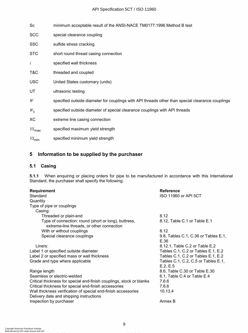
5 Information to be supplied by the purchaser
5.1 Casing
5.1.1 When enquiring or placing orders for pipe to be manufactured in accordance with this International Standard, the purchaser shall specify the following:
Requirement Reference Standard ISO 11960 or API 5CT Quantity Type of pipe or couplings
Casing: Threaded or plain-end 8.12 Type of connection: round (short or long), buttress, extreme-line threads, or other connection
8.12, Table C.1 or Table E.1
With or without couplings 8.12 Special clearance couplings 9.8, Tables C.1, C.36 or Tables E.1,
E.36 Liners: 8.12.1, Table C.2 or Table E.2
Label 1 or specified outside diameter Tables C.1, C.2 or Tables E.1, E.2 Label 2 or specified mass or wall thickness Tables C.1, C.2 or Tables E.1, E.2 Grade and type where applicable Tables C.1, C.2, C.5 or Tables E.1,
E.2, E.5 Range length 8.6, Table C.30 or Table E.30 Seamless or electric-welded 6.1, Table C.4 or Table E.4 Critical thickness for special end-finish couplings, stock or blanks 7.6.6 Critical thickness for special end-finish accessories 7.6.6 Wall thickness verification of special end-finish accessories 10.13.4 Delivery date and shipping instructions Inspection by purchaser Annex B
API Specification 5CT / ISO 11960
9Copyright American Petroleum Institute Reproduced by IHS under license with API
Not for ResaleNo reproduction or networking permitted without license from IHS
--`,,,```-`-`,,`,,`,`,,`---
ISO 11960:2004(E)
10 © ISO 2004 – All rights reserved
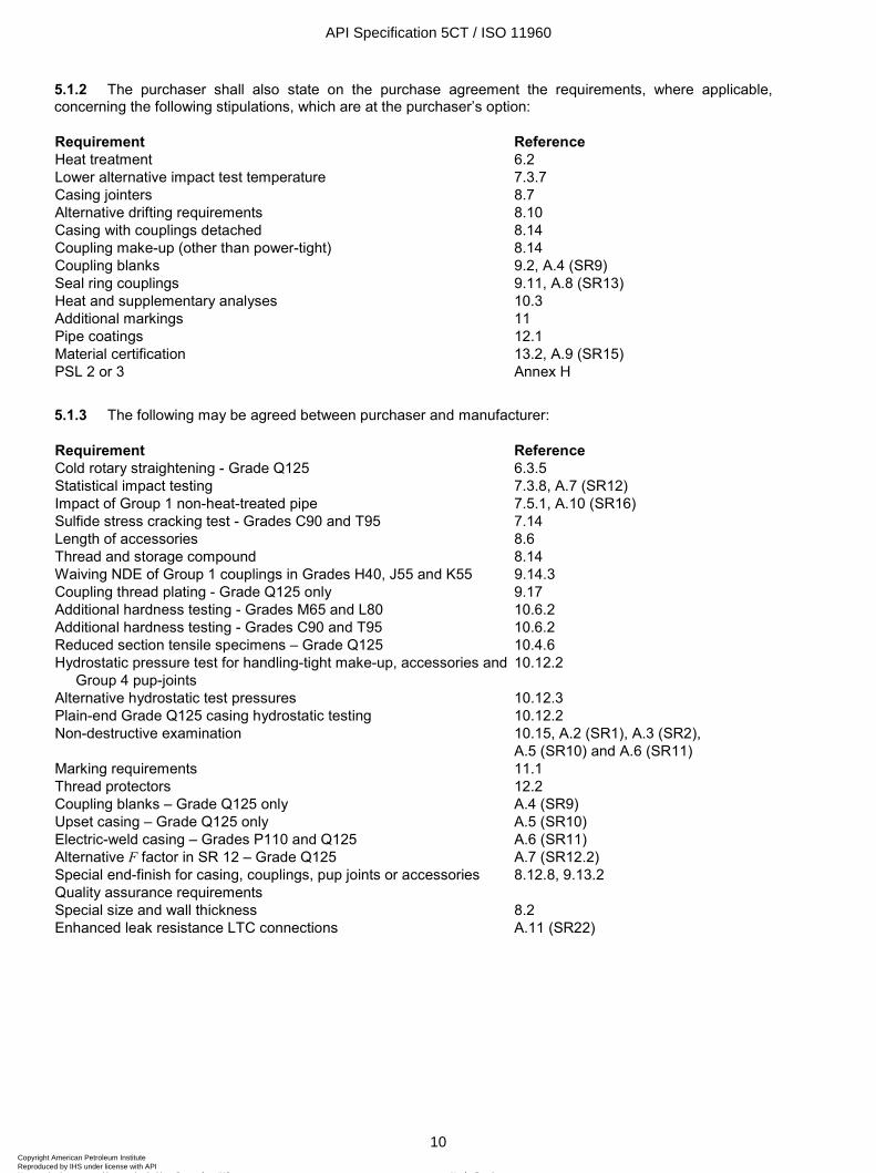
5.1.2 The purchaser shall also state on the purchase agreement the requirements, where applicable, concerning the following stipulations, which are at the purchaser’s option:
Requirement Reference Heat treatment 6.2 Lower alternative impact test temperature 7.3.7 Casing jointers 8.7 Alternative drifting requirements 8.10 Casing with couplings detached 8.14 Coupling make-up (other than power-tight) 8.14 Coupling blanks 9.2, A.4 (SR9) Seal ring couplings 9.11, A.8 (SR13) Heat and supplementary analyses 10.3 Additional markings 11 Pipe coatings 12.1 Material certification 13.2, A.9 (SR15) PSL 2 or 3 Annex H
5.1.3 The following may be agreed between purchaser and manufacturer:
Requirement Reference Cold rotary straightening - Grade Q125 6.3.5 Statistical impact testing 7.3.8, A.7 (SR12) Impact of Group 1 non-heat-treated pipe 7.5.1, A.10 (SR16) Sulfide stress cracking test - Grades C90 and T95 7.14 Length of accessories 8.6 Thread and storage compound 8.14 Waiving NDE of Group 1 couplings in Grades H40, J55 and K55 9.14.3 Coupling thread plating - Grade Q125 only 9.17 Additional hardness testing - Grades M65 and L80 10.6.2 Additional hardness testing - Grades C90 and T95 10.6.2 Reduced section tensile specimens – Grade Q125 10.4.6 Hydrostatic pressure test for handling-tight make-up, accessories and Group 4 pup-joints
10.12.2
Alternative hydrostatic test pressures 10.12.3 Plain-end Grade Q125 casing hydrostatic testing 10.12.2 Non-destructive examination 10.15, A.2 (SR1), A.3 (SR2),
A.5 (SR10) and A.6 (SR11) Marking requirements 11.1 Thread protectors 12.2 Coupling blanks – Grade Q125 only A.4 (SR9) Upset casing – Grade Q125 only A.5 (SR10) Electric-weld casing – Grades P110 and Q125 A.6 (SR11) Alternative F factor in SR 12 – Grade Q125 A.7 (SR12.2) Special end-finish for casing, couplings, pup joints or accessories 8.12.8, 9.13.2 Quality assurance requirements Special size and wall thickness 8.2 Enhanced leak resistance LTC connections A.11 (SR22)
API Specification 5CT / ISO 11960
10Copyright American Petroleum Institute Reproduced by IHS under license with API
Not for ResaleNo reproduction or networking permitted without license from IHS
--`,,,```-`-`,,`,,`,`,,`---
ISO 11960:2004(E)
© ISO 2004 – All rights reserved 11
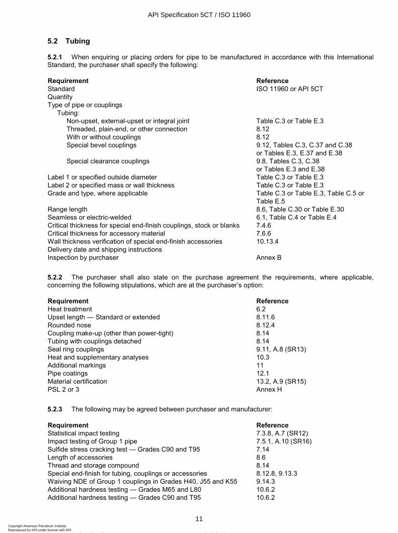
5.2 Tubing
5.2.1 When enquiring or placing orders for pipe to be manufactured in accordance with this International Standard, the purchaser shall specify the following:
Requirement Reference Standard ISO 11960 or API 5CT Quantity Type of pipe or couplings
Tubing: Non-upset, external-upset or integral joint Table C.3 or Table E.3 Threaded, plain-end, or other connection 8.12 With or without couplings 8.12 Special bevel couplings 9.12, Tables C.3, C.37 and C.38
or Tables E.3, E.37 and E.38 Special clearance couplings 9.8, Tables C.3, C.38
or Tables E.3 and E.38 Label 1 or specified outside diameter Table C.3 or Table E.3 Label 2 or specified mass or wall thickness Table C.3 or Table E.3 Grade and type, where applicable Table C.3 or Table E.3, Table C.5 or
Table E.5 Range length 8.6, Table C.30 or Table E.30 Seamless or electric-welded 6.1, Table C.4 or Table E.4 Critical thickness for special end-finish couplings, stock or blanks 7.4.6 Critical thickness for accessory material 7.6.6 Wall thickness verification of special end-finish accessories 10.13.4 Delivery date and shipping instructions Inspection by purchaser Annex B
5.2.2 The purchaser shall also state on the purchase agreement the requirements, where applicable, concerning the following stipulations, which are at the purchaser’s option:
Requirement Reference Heat treatment 6.2 Upset length — Standard or extended 8.11.6 Rounded nose 8.12.4 Coupling make-up (other than power-tight) 8.14 Tubing with couplings detached 8.14 Seal ring couplings 9.11, A.8 (SR13) Heat and supplementary analyses 10.3 Additional markings 11 Pipe coatings 12.1 Material certification 13.2, A.9 (SR15) PSL 2 or 3 Annex H
5.2.3 The following may be agreed between purchaser and manufacturer:
Requirement Reference Statistical impact testing 7.3.8, A.7 (SR12) Impact testing of Group 1 pipe 7.5.1, A.10 (SR16) Sulfide stress cracking test — Grades C90 and T95 7.14 Length of accessories 8.6 Thread and storage compound 8.14 Special end-finish for tubing, couplings or accessories 8.12.8, 9.13.3 Waiving NDE of Group 1 couplings in Grades H40, J55 and K55 9.14.3 Additional hardness testing — Grades M65 and L80 10.6.2 Additional hardness testing — Grades C90 and T95 10.6.2
API Specification 5CT / ISO 11960
11Copyright American Petroleum Institute Reproduced by IHS under license with API
Not for ResaleNo reproduction or networking permitted without license from IHS
--`,,,```-`-`,,`,,`,`,,`---
ISO 11960:2004(E)
12 © ISO 2004 – All rights reserved
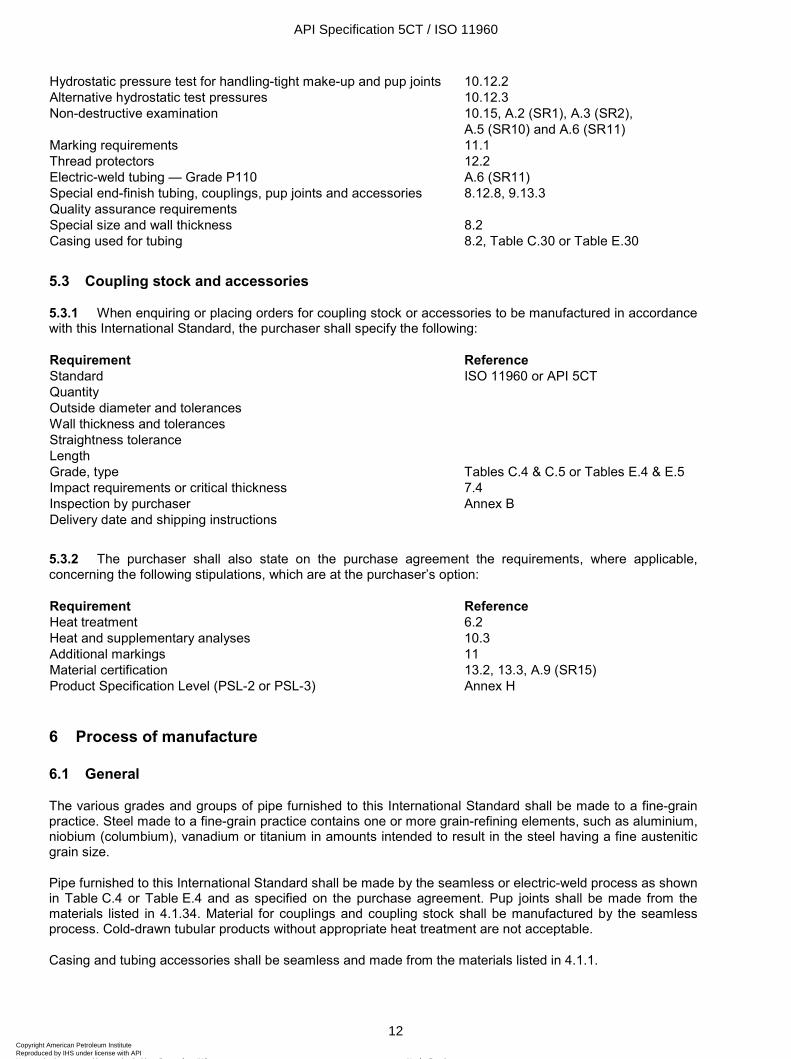
Hydrostatic pressure test for handling-tight make-up and pup joints 10.12.2 Alternative hydrostatic test pressures 10.12.3 Non-destructive examination 10.15, A.2 (SR1), A.3 (SR2),
A.5 (SR10) and A.6 (SR11) Marking requirements 11.1 Thread protectors 12.2 Electric-weld tubing — Grade P110 A.6 (SR11) Special end-finish tubing, couplings, pup joints and accessories 8.12.8, 9.13.3 Quality assurance requirements Special size and wall thickness 8.2 Casing used for tubing 8.2, Table C.30 or Table E.30
5.3 Coupling stock and accessories
5.3.1 When enquiring or placing orders for coupling stock or accessories to be manufactured in accordance with this International Standard, the purchaser shall specify the following:
Requirement Reference Standard ISO 11960 or API 5CT Quantity Outside diameter and tolerances Wall thickness and tolerances Straightness tolerance Length Grade, type Tables C.4 & C.5 or Tables E.4 & E.5 Impact requirements or critical thickness 7.4 Inspection by purchaser Annex B Delivery date and shipping instructions
5.3.2 The purchaser shall also state on the purchase agreement the requirements, where applicable, concerning the following stipulations, which are at the purchaser’s option:
Requirement Reference Heat treatment 6.2 Heat and supplementary analyses 10.3 Additional markings 11 Material certification 13.2, 13.3, A.9 (SR15) Product Specification Level (PSL-2 or PSL-3) Annex H
6 Process of manufacture
6.1 General
The various grades and groups of pipe furnished to this International Standard shall be made to a fine-grain practice. Steel made to a fine-grain practice contains one or more grain-refining elements, such as aluminium, niobium (columbium), vanadium or titanium in amounts intended to result in the steel having a fine austenitic grain size.
Pipe furnished to this International Standard shall be made by the seamless or electric-weld process as shown in Table C.4 or Table E.4 and as specified on the purchase agreement. Pup joints shall be made from the materials listed in 4.1.34. Material for couplings and coupling stock shall be manufactured by the seamless process. Cold-drawn tubular products without appropriate heat treatment are not acceptable.
Casing and tubing accessories shall be seamless and made from the materials listed in 4.1.1.
API Specification 5CT / ISO 11960
12Copyright American Petroleum Institute Reproduced by IHS under license with API
Not for ResaleNo reproduction or networking permitted without license from IHS
--`,,,```-`-`,,`,,`,`,,`---
ISO 11960:2004(E)
© ISO 2004 – All rights reserved 13
Electric-welded Grade P110 pipe and Grade Q125 casing shall be provided only when the supplementary requirement in A.5 (SR11) is specified on the purchase agreement.
Grade Q125 upset casing shall be provided only when the supplementary requirement in A.5 (SR10) is specified on the purchase agreement.
6.2 Heat treatment
6.2.1 General
Product shall be heat-treated in accordance with a documented procedure as stipulated in Table C.4 or Table E.4 for the particular grade and type specified on the purchase agreement. Heat-treated upset pipe shall be heat-treated full length after upsetting. Product requiring heat treatment shall be heat-treated the full length. Individually heat-treated coupling blanks are acceptable. All pipe processed through a hot-stretch mill (i.e. stretch-reduced) shall be considered normalized, provided the exit temperature is above the upper critical temperature (Ar3) for the steel being processed and the pipe is air-cooled.
The weld seam of electric-welded pipe shall be heat-treated after welding to a minimum temperature of 540 ºC (1 000 ºF) or processed in such a manner that no untempered martensite remains.
6.2.2 Group 1
Grade N80 Type 1 product shall be normalized or, at the manufacturer's option, shall be normalized and tempered. Grade N80Q product shall be quenched and tempered (including the interrupted quenching followed by controlled cooling method) full length. Grades J55 and K55 casing and Grade J55 tubing shall be heat-treated if so specified on the purchase agreement.
Additional requirements for PSL-2 and PSL-3 products are specified in Annex H.
6.2.3 Group 2
When requested by the purchaser, the manufacturer shall produce evidence to show that the tempering practice will result in the pipe attaining the minimum tempering temperature.
Grade L80 13Cr may be subject to embrittlement when tempered below 620 ºC (1 150 ºF). When all product meets the requirements in 7.3, 7.4.5, 7.5.3 and 10.7, no further precautions are necessary.
NOTE In this International Standard when the symbol L80 is used alone it covers Grades L80 Type 1, L80 9Cr and L80 13Cr.
6.2.4 Groups 3 and 4
Product furnished to this International Standard shall be quenched and tempered.
6.3 Straightening
6.3.1 Groups 1 and 3
No specific methods are required.
Additional requirements for PSL-2 and PSL-3 products are specified in Annex H.
6.3.2 Grades M65 and L80
Grades M65 and L80 shall not be subjected to cold working after the final heat treatment, except for that which is incidental to normal straightening operations. Grades M65 and L80 pipe rotary-straightened at
API Specification 5CT / ISO 11960
13Copyright American Petroleum Institute Reproduced by IHS under license with API
Not for ResaleNo reproduction or networking permitted without license from IHS
--`,,,```-`-`,,`,,`,`,,`---
ISO 11960:2004(E)
14 © ISO 2004 – All rights reserved
temperatures less than 480 ºC (900 ºF) shall not contain roll marks that exceed the maximum hardness specified in Table C.6 or Table E.6; however:
― roll marks that are not detectable by feel and have no measurable surface deformation are acceptable without further evaluation;
― roll marks that are not more severe than those previously evaluated and verified by the manufacturer in a documented procedure not to exceed the maximum hardness specified in Table C.6 or Table E.6 are acceptable without further evaluation;
― pipe with severe roll marks shall be either rejected or stress-relieved at 480 ºC (900 ºF) minimum.
6.3.3 Grade C95
Grade C95 pipe shall be subjected to no tensile or expansion cold-working, except that which is incidental to normal straightening operations, and to no more than 3 % compressive cold-working, after the final tempering operation.
Additional requirements for PSL-2 and PSL-3 products are specified in Annex H.
6.3.4 Grades C90 and T95
Grades C90 and T95 pipe may be subjected to cold rotary-straightening if, subsequent to the cold rotary-straightening operation, the pipe is heated to a minimum temperature of 480 ºC (900 ºF) for stress-relieving. When necessary, light gag-straightening for Grades C90 and T95 shall be permitted.
Additional requirements for PSL-2 and PSL-3 products are specified in Annex H.
6.3.5 Grade Q125
Gag-press straightening or hot rotary-straightening at 400 ºC (750 ºF) minimum at the end of rotary-straightening is acceptable (unless a higher minimum temperature is specified on the purchase agreement). If hot rotary-straightening is not possible, the pipe may be cold rotary-straightened provided it is then stress-relieved at 510 ºC (950 ºF) or higher. Pipe may be cold rotary-straightened without subsequent stress-relieving only by agreement between purchaser and manufacturer.
6.4 Traceability
6.4.1 General
The manufacturer shall establish and follow procedures for maintaining heat and/or lot identity until all required heat and/or lot tests are performed and conformance with specification requirements has been shown.
6.4.2 Serialization of Grades C90, T95 and Q125
The serial number shall be marked on products as specified below. It is the responsibility of the manufacturer to maintain the identification of material until it is received by the purchaser.
Each length of pipe shall be uniquely numbered so that test data can be related to individual lengths. In addition, when supplementary requirement A.7 (SR12) is specified, the number shall identify the sequence in which the lengths were tempered in order to allow re-test in accordance with A.7.3 (SR12.3).
Each length of coupling stock, coupling, pup joint or accessory material shall be uniquely numbered so that test data can be related to individual lengths. When cut from material that has been heat-treated full length, the pieces shall be marked with the serial number of the full length piece. When heat-treated in coupling blank or individual lengths, each heat-treat lot (see 10.2.3) shall be uniquely numbered. Additionally, when coupling,
API Specification 5CT / ISO 11960
14Copyright American Petroleum Institute Reproduced by IHS under license with API
Not for ResaleNo reproduction or networking permitted without license from IHS
--`,,,```-`-`,,`,,`,`,,`---
ISO 11960:2004(E)
© ISO 2004 – All rights reserved 15
pup joint or accessory materials in coupling blanks or individual lengths are heat-treated as a unit in a continuous process-run, the pieces within the lot shall be sequentially numbered in the order in which they are heat-treated.
6.5 Processes requiring validation
Final operations performed during pipe manufacturing that affect attribute compliance as required in this International Standard (except chemical composition and dimensions) shall have their processes validated.
Those processes requiring validation are:
for seamless, as-rolled pipe: final reheating practice and hot sizing or stretch-reducing. If applicable, upsetting, cold finishing;
for seamless, heat-treated pipe: heat treatment;
for electric-welded, as-rolled pipe: sizing and seam welding. If applicable, seam heat treatment and upsetting;
for electric-welded, heat-treated pipe: seam welding and full-body heat treatment.
7 Material requirements
7.1 Chemical composition
Product shall conform to the requirements specified in Table C.5 or Table E.5 for the grade and type specified.
Additional requirements for PSL-2 and PSL-3 products are specified in Annex H.
7.2 Tensile properties
7.2.1 General
Product shall conform to the tensile requirements specified in Table C.6 or Table E.6.
The tensile properties of upset casing and tubing, except elongation of the upset ends, shall comply with the requirements given for the pipe body. In case of dispute, the properties (except elongation) of the upset shall be determined from a tensile test specimen cut from the upset. A record of such tests shall be available to the purchaser.
7.2.2 Elongation — All groups
The minimum elongation shall be that determined by the following equation:
0,2
0,9Ae kU
= ×
where
e is the minimum gauge length extension in 50,8 mm (2.0 in), expressed in percent, rounded to the nearest 0,5 % below 10 % and to the nearest unit percent for 10 % and larger;
k is a constant: 1 944 (625 000);
API Specification 5CT / ISO 11960
15Copyright American Petroleum Institute Reproduced by IHS under license with API
Not for ResaleNo reproduction or networking permitted without license from IHS
--`,,,```-`-`,,`,,`,`,,`---
ISO 11960:2004(E)
16 © ISO 2004 – All rights reserved
A is the cross-sectional area of the tensile test specimen, expressed in square millimetres (square inches), based on specified outside diameter or nominal specimen width and specified wall thickness, rounded to the nearest 10 mm2 (0.01 in2), or 490 mm2 (0.75 in2) whichever is smaller;
U is the minimum specified tensile strength, in megapascals (pounds per square inch).
The minimum elongation for both round-bar tensile specimens [8,9 mm (0.350 in) diameter with 35,6 mm (1.40 in) gauge length and 12,7 mm (0.500 in) diameter with 50,8 mm (2.0 in) gauge length] shall be determined using an area A of 130 mm2 (0.20 in2).
Table C.7 or Table E.7 gives minimum elongation values for various sizes of tensile specimens and for various grades.
7.2.3 Yield strength
The yield strength shall be the tensile stress required to produce the elongation under load specified in Table C.6 or Table E.6 as determined by an extensometer.
Additional requirements for PSL-3 products are specified in Annex H.
7.3 Charpy V-notch test — General requirements
7.3.1 Evaluation of test results
A test shall consist of a set of three specimens taken from one location from a single tubular product length. The average value of the three impact specimens shall equal or exceed the absorbed energy requirement specified in 7.4, 7.5 and 7.6. In addition, not more than one impact specimen shall exhibit an absorbed energy below the absorbed energy requirement, and in no case shall an individual impact specimen exhibit an absorbed energy below two-thirds of the absorbed energy requirement.
Additional requirements for PSL-2 and PSL-3 products are specified in Annex H.
7.3.2 Critical thickness
The absorbed energy requirements are based on the critical thickness. The critical thickness for couplings with API threads is the thickness at the root of the thread at the middle of the coupling, based on the specified coupling diameter and the specified thread dimensions. The critical thickness for all couplings with API threads is provided in Table C.8 or Table E.8. For pipe, the critical thickness is the specified wall thickness. For other applications, the critical thickness shall be determined as specified in 7.6.6.
7.3.3 Specimen size and orientation
When the use of full-size (10 mm × 10 mm) transverse test specimens is not possible, the largest possible sub-size transverse test specimen listed in Table C.9 or Table E.9 shall be used. When it is not possible (or allowed in accordance with 7.3.6) to test using any of these transverse test specimens, the largest possible longitudinal test specimen listed in Table C.9 or Table E.9 shall be used.
When testing EW pipe using a transverse test specimen, the weld line shall be positioned at the notch in the Charpy test specimen.
When the outside diameter or wall thickness precludes the machining of longitudinal impact test specimens ½-size or larger, the pipe need not be tested; however, the manufacturer shall use a chemical composition and processing that is documented and demonstrated to result in impact-energy absorption which meets or exceeds the minimum specified requirement.
API Specification 5CT / ISO 11960
16Copyright American Petroleum Institute Reproduced by IHS under license with API
Not for ResaleNo reproduction or networking permitted without license from IHS
--`,,,```-`-`,,`,,`,`,,`---
ISO 11960:2004(E)
© ISO 2004 – All rights reserved 17
7.3.4 Hierarchy of test specimens
The hierarchy of test specimen orientation and size is specified in Table C.10 or Table E.10.
7.3.5 Alternative size impact test specimens
At the manufacturer's option, impact test specimens of an alternative size, listed in Table C.9 or Table E.9, may be used in lieu of the minimum size specified in Tables C.11 through C.16, C.21, C.22 and Tables E.11 through E.16, E.21 and E.22. However, the alternative test specimen selected shall be higher on the hierarchy table (Table C.10 or Table E.10) than the specified size, and the absorbed energy requirement shall be adjusted consistent with the orientation and size of the impact specimen.
7.3.6 Sub-size test specimens
The minimum CVN absorbed energy requirement for sub-size test specimens shall be that specified for a full-size test specimen multiplied by the reduction factor in Table C.9 or Table E.9; however, in no event shall a sub-size test specimen be used if the reduced absorbed-energy requirement is less than 11 J (8 ft⋅lb).
7.3.7 Test temperature
The test temperature shall be 0 ºC (32 ºF) for all groups except Group 1, Grades J55 and K55. Grades J55 and K55 shall be tested at 21 ºC (70 ºF). An alternative lower test temperature may be specified on the purchase agreement or selected by the manufacturer for any grade. The tolerance on the test temperature shall be ± 3 ºC (± 5 ºF).
A reduction in test temperature may be required for Grades J55 and K55 when sub-size specimens are used. The amount of test-temperature reduction depends on the critical thickness of the connection and the size of the impact test specimen. The test-temperature reduction specified in Table C.11 or Table E.11 shall be used when applicable.
7.3.8 Statistical impact testing
By agreement between purchaser and manufacturer, the supplementary requirements for statistical impact testing in A.7 (SR 12) shall apply.
7.3.9 Reference information
ISO 10400 or API Bul 5C3 includes reference information on fracture mechanics and equations and tables used in preparing impact requirements.
7.4 Charpy V-notch test — Absorbed energy requirements for coupling stock, coupling blanks and couplings
7.4.1 General
Coupling stock suitable for more than one type of connection may be qualified by a test to demonstrate conformance to the most stringent requirements. The test specimen orientation and size shall be the highest possible listed on the hierarchy in Table C.10 or Table E.10 and the absorbed energy requirement shall equal or exceed the applicable requirements.
7.4.2 Grade H40
There is no mandatory CVN impact energy requirement.
NOTE See A.10 (SR16) for optional CVN requirements.
API Specification 5CT / ISO 11960
17Copyright American Petroleum Institute Reproduced by IHS under license with API
Not for ResaleNo reproduction or networking permitted without license from IHS
--`,,,```-`-`,,`,,`,`,,`---
ISO 11960:2004(E)
18 © ISO 2004 – All rights reserved
7.4.3 Grades J55 and K55 for API threads
The minimum full-size transverse absorbed energy requirement CV is 20 J (15 ft⋅lb). The minimum full-size longitudinal absorbed energy requirement CV is 27 J (20 ft⋅lb). The impact specimen orientation, minimum size, minimum absorbed energy requirement (that is, adjusted for the size of specimen indicated), and test temperature reduction (as applicable) for couplings are provided in Table C.11 or Table E.11.
7.4.4 Grade M65 for API threads
There are no Grade M65 couplings. Grade L80 Type 1 couplings shall be used on Grade M65 pipe.
7.4.5 Grades N80 Type 1 and N80Q, Groups 2 (except M65), 3 and 4 for API threads
The impact specimen orientation, minimum size and minimum absorbed energy requirement CV (i.e. adjusted for the specimen size indicated) for couplings are provided in Tables C.12 to C.16 or Tables E.12 to E.16.
The minimum absorbed energy requirements, CV, for full-size test specimens are calculated based on the equations below, where:
YSmax is the specified maximum yield strength for the grade evaluated, in megapascals (thousand pounds per square inch);
t is the critical wall thickness, in millimetres (inches), based on the specified dimensions for couplings.
Unit system Transverse requirement
CV
Longitudinal requirement
CV
SI units, joules YSmax • (0,001 18 • t + 0,012 59)
or 20 J, whichever is greater
(Table C.17)
YSmax • (0,002 36 • t + 0,025 18)
or 41 J, whichever is greater
(Table C.18)
USC units, foot-pounds YSmax • (0.152 • t + 0.064)
or 15 ft⋅lb whichever is greater
(Table E.17)
YSmax • (0.304 • t + 0.128)
or 30 ft⋅lb, whichever is greater
(Table E.18)
7.4.6 Special end-finish
The critical thickness shall be as specified in 7.6.6. The absorbed energy requirements in 7.4.1 to 7.4.5 shall apply.
7.5 Charpy V-notch test — Absorbed energy requirements for pipe
7.5.1 Grades H40, J55, K55 and N80 Type 1
There is no mandatory CVN impact requirement.
Additional requirements for PSL-2 and PSL-3 products are specified in Annex H.
NOTE See A.10 (SR16) for optional CVN impact energy requirements.
7.5.2 Grade M65
The minimum full-size transverse absorbed energy requirement shall be 20 J (15 ft⋅lb). The minimum full-size longitudinal absorbed energy requirement shall be 41 J (30 ft⋅lb).
API Specification 5CT / ISO 11960
18Copyright American Petroleum Institute Reproduced by IHS under license with API
Not for ResaleNo reproduction or networking permitted without license from IHS
--`,,,```-`-`,,`,,`,`,,`---
ISO 11960:2004(E)
© ISO 2004 – All rights reserved 19
7.5.3 Grades N80Q, L80, C90, C95, T95 and P110
The minimum absorbed energy requirement, CV, for full-size test specimens is provided in Tables C.19 and C.20 or Tables E.19 and E.20.
Additional requirements for PSL-2 and PSL-3 products are specified in Annex H.
The requirements are calculated based on the equations given below, where:
YSmin is the specified minimum yield strength, in megapascals (thousand pounds per square inch);
t is the specified wall thickness, in millimetres (inches).
Unit system and grade Transverse requirement CV
Longitudinal requirement CV
SI units, joules
Grades N80Q, L80, C90, C95, T95
YSmin • (0,001 18 • t + 0,012 59)
or 14 J, whichever is greater
(Table C.19)
YSmin • (0,002 36 • t + 0,025 18)
or 27 J, whichever is greater
(Table C.20)
SI units, joules
Grade P110
YSmin • (0,001 18 • t + 0,012 59)
or 20 J, whichever is greater
(Table C.19)
YSmin • (0,002 36 • t + 0,025 18)
or 41 J, whichever is greater
(Table C.20)
USC units, foot pounds
Grades N80Q, L80, C90, C95, T95
YSmin • (0.152 • t + 0.064)
or 10 ft⋅lb, whichever is greater
(Table E.19)
YSmin • (0.304 • t + 0.128)
or 20 ft⋅lb, whichever is greater
(Table E.20)
USC units, foot pounds
Grade P110
YSmin • (0.152 • t + 0.064)
or 15 ft⋅lb, whichever is greater
(Table E.19)
YSmin • (0.304 • t + 0.128)
or 30 ft⋅lb, whichever is greater
(Table E.20)
7.5.4 Grade Q125
The minimum absorbed energy requirement for full-size test specimens is provided in Tables C.19 and C.20 or Tables E.19 and E.20.
Additional requirements for PSL-2 and PSL-3 products are specified in Annex H.
The requirements are calculated based on the equations given below where:
YSmax is the specified maximum yield strength, in megapascals (1 034 MPa) [thousand pounds per square inch (150 ksi)];
t is the specified wall thickness, in millimetres (inches).
Unit system Transverse requirement
CV
Longitudinal requirement
CV
SI units, joules
Grade Q125
YSmax • (0,001 18 • t + 0,012 59)
or 20 J whichever is greater
(Table C.19)
YSmax • (0,002 36 • t + 0,025 18)
or 41 J whichever is greater
(Table C.20)
USC units, foot pounds
Grade Q125
YSmax • (0.152 • t + 0.064)
or 15 ft⋅lb whichever is greater
(Table E.19)
YSmax • (0.304 • t + 0.128)
or 30 ft⋅lb, whichever is greater
(Table E.20)
API Specification 5CT / ISO 11960
19Copyright American Petroleum Institute Reproduced by IHS under license with API
Not for ResaleNo reproduction or networking permitted without license from IHS
--`,,,```-`-`,,`,,`,`,,`---
ISO 11960:2004(E)
20 © ISO 2004 – All rights reserved
7.5.5 Test specimen
Table C.21 or Table E.21 for transverse specimens and Table C.22 or Table E.22 for longitudinal specimens provide the calculated wall thickness required to machine full-size, ¾-size, and ½-size impact test specimens. The impact test specimen size that shall be selected from these tables is the largest impact test specimen having a calculated wall thickness that is less than the specified wall thickness for the pipe tested.
7.5.6 Testing conditions
For Grades M65 and Q125 pipe, impact testing in accordance with 10.7 is mandatory. For all other grades except Grades H40, J55, K55 and N80 Type 1 (which have no mandatory impact requirements for pipe), compliance with the requirements of 7.5.3 may be qualified by a documented procedure in lieu of testing, at the manufacturer's option, unless A.10 (SR16) is specified on the purchase agreement, in which case testing is mandatory as specified in 10.7. Pipe qualified by a documented procedure that fails to show conformance to the specified impact energy requirements after shipment shall be rejected.
7.6 Charpy V-notch test — Absorbed energy requirements for casing and tubing accessories
7.6.1 Accessories — General
If the accessory has an API internally threaded connection, the minimum impact energy requirement for the accessory shall not be less than the requirement for that particular connection.
7.6.2 Accessories with internal API threads except integral joint tubing connections and extreme line casing connections
The requirements in 7.4.1 to 7.4.5 apply.
7.6.3 Accessories with internal special end-finish tapered interference-type threads
The requirements in 7.4.6 apply.
7.6.4 Accessories with external threads
The requirements in 7.5 apply.
7.6.5 Accessories with either integral joint tubing connections, extreme line casing connections or internal special end-finish connections that do not have thread interference
By agreement between the manufacturer and purchaser, the provisions of A.10 (SR16) shall apply.
7.6.6 Critical thickness for accessory material
If not specified on the purchase agreement, the critical thickness for determining the impact energy requirements shall be based on the thickness of the cross-section of the accessory that has the lowest t/D ratio, where D is the specified outside diameter and t is the calculated wall thickness at that section.
For an accessory with API internal threads, the critical thickness for these API threads is shown in Table C.8 or Table E.8, and D is the specified outside diameter of the connection as specified in 9.6 and 9.8.
For special end-finish connections, the critical thickness for externally threaded members is the specified pipe body thickness, while for internally threaded members it is the calculated thickness of the internally threaded member at the plane of the small end of the pin (when the connection is made up power-tight).
API Specification 5CT / ISO 11960
20Copyright American Petroleum Institute Reproduced by IHS under license with API
Not for ResaleNo reproduction or networking permitted without license from IHS
--`,,,```-`-`,,`,,`,`,,`---
ISO 11960:2004(E)
© ISO 2004 – All rights reserved 21
7.7 Maximum hardness
7.7.1 Group 2 — All product
The following hardness requirements are applicable if required in accordance with 10.6:
a) Grades M65, L80 all types, C90 and T95
The hardness numbers and/or mean hardness numbers obtained shall comply with the requirements in Table C.6 or Table E6.
b) Grades C90 and T95 — Surface hardness
If the Brinell or Rockwell C-scale hardness number does not exceed 255 HBW or 25,4 HRC respectively, then the length or piece is acceptable. If any of the hardness numbers are over 255 HBW or 25,4 HRC two additional indentations may be made in the immediate area. If either of the second test hardness numbers exceeds 255 HBW or 25,4 HRC the length or piece shall be rejected.
c) Grades C90 and T95 — Through-wall hardness
Products with mean Rockwell hardness number not exceeding 25,4 HRC are acceptable. If any hardness number from a single indentation exceeds 27,0 HRC, the length or piece shall be rejected. Products with mean hardness numbers between 25,4 HRC and 27,0 HRC shall be retested.
d) Grades C90 and T95 — Alternative maximum hardness requirements
By agreement between the purchaser and manufacturer, the maximum mean hardness numbers may be altered from those stated above, based on sulfide stress corrosion cracking tests specified in 7.14.
7.7.2 Grade Q125 — All products
There are no upper or lower hardness limits for these products.
7.8 Hardness variation — Grades C90, T95 and Q125
Material shall conform to the hardness variation requirements of Table C.6 or Table E.6. Hardness variation is defined as the difference between any two mean hardness numbers within one quadrant. This criterion shall not apply between specimens.
7.9 Process control — Grades C90, T95 and Q125
All individually heat-treated coupling blanks, pup joints or accessories shall be surface hardness-tested to verify process control. For Grades C90 and T95, the surface hardness test results shall be used in the selection of the pieces for through-wall hardness testing. The process-control hardness test results need not be provided by the manufacturer or processor unless specified on the purchase agreement.
7.10 Hardenability — Minimum percentage martensite for quenched and tempered products
7.10.1 Grades C90 and T95
For each size, mass, chemical composition and austenitize-and-quench combination, a through-wall hardness test shall be made on products after quenching and prior to tempering for each production run to characterize the hardening response. These tests shall be made on the body of products or, in the case of upset products or accessories, shall be made in the upset or design area of greatest wall thickness. Mean hardness numbers shall equal or exceed the hardness corresponding to a minimum of 90 % martensite, as determined by the following equation:
HRCmin = 58 × (% carbon) + 27
API Specification 5CT / ISO 11960
21Copyright American Petroleum Institute Reproduced by IHS under license with API
Not for ResaleNo reproduction or networking permitted without license from IHS
--`,,,```-`-`,,`,,`,`,,`---
ISO 11960:2004(E)
22 © ISO 2004 – All rights reserved
NOTE The above equation was derived from data in reference [2]. Based on these data, the above equation is valid from 0,15 % carbon to 0,50 % carbon.
Additional requirements for PSL-3 products are specified in Annex H.
7.10.2 All grades except Grades C90 and T95
For each size, mass, chemical composition and austenitize-and-quench combination, a through-wall hardness test shall be made after quenching and prior to tempering as part of a documented procedure to confirm sufficient hardening. These tests shall be made on the body of products or, in the case of upset products or accessories, shall be made in the upset or design area of greatest wall thickness. Mean hardness numbers shall equal or exceed the hardness corresponding to a minimum of 50 % martensite, as determined by the following equation:
HRCmin = 52 × (% carbon) + 21
Additional requirements for PSL-2 and PSL-3 products are specified in Annex H.
7.11 Grain size — Grades C90 and T95
Prior austenitic grain size shall be ASTM 5 or finer (determined in accordance with ISO 643 or ASTM E112).
7.12 Surface condition — Grades L80 9Cr and L80 13Cr
The internal surface of the pipe shall be free from scale after the final heat treatment.
Additional requirements for PSL-2 and PSL-3 products are specified in Annex H.
7.13 Flattening — Electric-welded pipe
All products that are produced by the electric-weld process of manufacture shall comply with the flattening requirements shown in Table C.23 or Table E.23.
7.14 Sulfide stress cracking test — Grades C90 and T95
7.14.1 Test and re-test requirements
For each heat, manufacturers shall demonstrate that the product meets or exceeds the minimum SSC threshold using one of the ANSI-NACE TM0177-96 test methods given below. If the purchaser requires an SSC threshold higher than the minimum, or requires a specific test method from the list below, agreement shall be reached between purchaser and manufacturer. For Methods A and D, sub-size or alternative specimens shall only be used following agreement with the purchaser. When Method D sub-size or alternative specimens are required, acceptance criteria shall be agreed between the purchaser and manufacturer.
Additional requirements for PSL-3 products are specified in Annex H.
The details of a manufacturer’s qualification, frequency of sulfide stress cracking testing, re-test procedures and testing practices should be addressed by the purchaser and the manufacturer prior to placing or accepting a purchase order.
API Specification 5CT / ISO 11960
22Copyright American Petroleum Institute Reproduced by IHS under license with API
Not for ResaleNo reproduction or networking permitted without license from IHS
--`,,,```-`-`,,`,,`,`,,`---
ISO 11960:2004(E)
© ISO 2004 – All rights reserved 23
7.14.2 Minimum SSC threshold values
a) ANSI-NACE TM0177-96 Method A, Smooth tensile
Full-size (6,35 mm [0.250 in] diameter) specimen: 80 % of YSmin 496 MPa (72 000 psi) for C90
524 MPa (76 000 psi) for T95
Sub-size (3,81 mm [0.150 in] diameter) specimen: 72 % of YSmin 447 MPa (64 800 psi) for C90
472 MPa (68 400 psi) for T95
b) ANSI-NACE TM0177-96 Method B, Bent beam Sc (12.0) for C90
Sc (12.6) for T95
NOTE The requirement for Method B is only stated in USC units, based on current industry convention.
c) ANSI-NACE TM0177-96 Method D, DCB
A mean value of 33,0 MPa⋅m1/2 (30.0 ksi⋅in1/2) with a minimum of at least three valid test specimens for Grades C90 and T95. All valid test results shall be included when calculating the mean value.
A standard test specimen thickness of 9,53 mm (0.375 in) shall be used.
No valid test specimen shall have a value less than 30,0 MPa⋅m1/2 (27.0 ksi⋅in1/2).
Either non-pre-cracked or fatigue pre-cracked specimens may be used. If fatigue pre-cracking of specimens is employed, the maximum stress intensity factor during pre-cracking shall not exceed 30,0 MPa⋅m1/2 (27.0 ksi⋅in1/2).
For Grade C90, the arm displacement shall be 0,70 mm to 0,80 mm (0.028 in to 0.032 in)
For Grade T95, the arm displacement shall be 0,66 mm to 0,76 mm (0.026 in to 0.030 in)
7.14.3 Test temperature
The test solution shall be maintained at 24 ºC ± 3 ºC (75 ºF ± 5 ºF).
7.14.4 Test solution
For the purposes of this International Standard, ANSI-NACE TM0177-96 Test Solution A shall be used. To prevent conflict arising from future revisions, the properties of the test solution shall be:
a) for Test Methods A and D:
The test solution shall have a pH in the range 2,6 to 2,8 before contacting the test specimen.
The test solution shall have 5,0 % mass fraction sodium chloride and 0,5 % mass fraction glacial acetic acid dissolved in distilled or de-ionized water.
The test solution shall be saturated with hydrogen sulfide (H2S) as described in ANSI-NACE TM0177-96.
b) for Test Method B:
The test solution shall have a pH in the range 2,6 to 2,8 before contacting the test specimen.
API Specification 5CT / ISO 11960
23Copyright American Petroleum Institute Reproduced by IHS under license with API
Not for ResaleNo reproduction or networking permitted without license from IHS
--`,,,```-`-`,,`,,`,`,,`---
ISO 11960:2004(E)
24 © ISO 2004 – All rights reserved
The test solution shall have 0,5 % mass fraction glacial acetic acid dissolved in distilled or de-ionized water.
The test solution shall be saturated with H2S as described in ANSI-NACE TM0177-96.
8 Dimensions, masses, tolerances, pipe ends and defects
8.1 Labels and sizes
In the dimensional tables in this International Standard, pipe is designated by labels and by size (outside diameter). The outside diameter size of external-upset pipe is the outside diameter of the body of the pipe, not the upset portion.
8.2 Dimensions and masses
Pipe shall be furnished in the sizes, wall thicknesses and masses (as shown in Tables C.24 to C.29 inclusive or Tables E.24 to E.29 inclusive) as specified on the purchase agreement. Other plain-end pipe sizes and wall thicknesses may be furnished by agreement between purchaser and manufacturer. Coupling stock shall be furnished in dimensions as specified on the purchase agreement. Coupling stock outside diameter and wall thickness combinations shall exclude those in Tables C.1, C.2, C.3 or Tables E.1, E.2, E.3. All dimensions shown without tolerances are related to the basis for design and are not subject to measurement to determine acceptance or rejection of product.
Casing sizes larger than Label 1: 4-1/2 but smaller than Label 1: 10-3/4 may be specified by the purchaser to be used in tubing service, see Tables C.1, C.24, C.30 and C.31 or Tables E.1, E.24, E.30 and E.31.
The accuracy of all measuring equipment used for acceptance or rejection, except ring-and-plug thread gauges and weighing devices, shall be verified at least every operating shift.
Verifying the accuracy of measuring devices such as snap gauges and drift mandrels shall consist of inspection for wear and conformance to specified dimensions. Verifying the accuracy of rules, length-measuring tapes and other non-adjustable measuring devices shall consist of a visual check for the legibility of markings and general wear of fixed reference points. The adjustable and non-adjustable designations of measuring devices utilized by the manufacturer shall be documented.
The verification procedure for working ring-and-plug thread gauges shall be documented. The accuracy of all weighing devices shall be verified at periods not to exceed those required by the manufacturer’s documented procedure in accordance with National Institute of Standards and Technology (NIST) standards or equivalent regulations in the country of manufacture of products made to this International Standard.
If measuring equipment whose calibration or verification is required under the provisions of this International Standard is subjected to unusual or severe conditions sufficient to make its accuracy questionable, re-calibration or re-verification shall be performed before further use of the equipment.
8.3 Diameter
8.3.1 Measurement and design
a) Using SI units
For measurement of diameter, an accuracy of one decimal place shall be used for sizes larger than Label 1: 6-5/8. In this International Standard two decimal places are used for design purposes to ensure interchangeability.
b) Using USC units
The diameter shall be rounded to three decimal places.
API Specification 5CT / ISO 11960
24Copyright American Petroleum Institute Reproduced by IHS under license with API
Not for ResaleNo reproduction or networking permitted without license from IHS
--`,,,```-`-`,,`,,`,`,,`---
ISO 11960:2004(E)
© ISO 2004 – All rights reserved 25
8.3.2 Requirements
The outside diameter shall be within the tolerances specified in 8.11.1. For threaded pipe, the outside diameter at the threaded ends shall be such that the thread length, L4, and the full-crest thread length, Lc, are within the tolerances and dimensions specified in API Spec 5B. For pipe furnished non-upset and plain-end and which is specified on the purchase agreement for the manufacture of pup joints, the non-upset plain-end tolerances shall apply to the full length.
8.4 Wall thickness
For pipe, the wall thickness at any place shall not be less than the tabulated thickness, t, minus the permissible under-tolerance specified in 8.11.2.
For coupling stock, the wall thickness tolerance shall be as specified on the purchase agreement.
8.5 Mass
The masses determined as described in 10.13.7 shall conform to the calculated masses as specified herein (or adjusted calculated masses) for the end-finish specified on the purchase agreement, within the tolerances stipulated in 8.11.3. Calculated masses shall be determined in accordance with the following formula:
pe( )L mm m L e= ⋅ +
where
mL is the calculated mass of a piece of pipe of length L, in kilograms (pounds);
mpe is the plain-end mass, in kilograms per metre (pounds per foot);
L is the length of pipe, including end-finish, in metres (feet), as defined in 8.6;
em is the mass gain or loss due to end-finishing, in kilograms (pounds). For plain-end non-upset pipe, em = 0.
NOTE The densities of martensitic chromium steels (L80 Types 9Cr and 13Cr) are less than those of carbon steels. The masses shown are therefore not accurate for martensitic chromium steels. A mass correction factor of 0,989 may be used.
8.6 Length
Casing, tubing, plain-end liners, and pup joints shall be furnished in lengths conforming to Table C.30 or Table E.30. The length of coupling stock and accessories, except couplings, shall be as specified on the purchase agreement. The length of each finished pipe shall be determined for conformance to length requirements. Length determination shall be in metres and hundredths of a metre (feet and tenths of a foot).
The accuracy of length-measuring devices for lengths of pipe less than 30 m (100 ft) shall be ± 0,03 m (± 0.1 ft).
8.7 Casing jointers
If so specified on the purchase agreement, for round thread casing only, jointers (two pieces coupled to make a standard length) may be furnished to a maximum of 5 % of the order; but no length used in making a jointer shall be less than 1,52 m (5.0 ft).
API Specification 5CT / ISO 11960
25Copyright American Petroleum Institute Reproduced by IHS under license with API
Not for ResaleNo reproduction or networking permitted without license from IHS
--`,,,```-`-`,,`,,`,`,,`---
ISO 11960:2004(E)
26 © ISO 2004 – All rights reserved
8.8 Height and trim of electric-weld flash
8.8.1 Trimming electric-weld flash
The outside flash of electric-welded pipe shall be trimmed to an essentially flush condition.
It shall be the aim of the manufacturer to provide an inside surface at the weld of electric-weld pipe that is:
a) reasonably close to flush after trimming; and
b) contains no jagged edges from the original weld flash.
It may be desirable for the manufacturer to provide an inside surface at the trimmed weld with a slight groove in order to meet this aim. The inside flash of electric-welded pipe shall be trimmed as given in 8.8.2 and 8.8.3.
8.8.2 Groups 1 and 2
The height of the inside weld flash shall not exceed 1,14 mm (0.045 in) for casing or casing pup joints or 0,38 mm (0.015 in) for tubing or tubing pup joints, measured from the inside surface adjacent to the flash.
The depth of groove resulting from removal of the inside flash shall not be greater than the amount listed below for the various wall thicknesses. Depth of groove is the difference between the wall thickness measured approximately 25 mm (1 in) from the weld line and the remaining wall under the groove.
Wall thickness Maximum depth of trim
3,84 mm to 7,64 mm (0.151 in to 0.301 in) 0,38 mm (0.015 in)
W 7,64 mm (W 0.301 in) 0,05 • t
8.8.3 Groups 3 and 4
No inside flash height shall be permitted. The groove on the inside weld surface shall not exceed a depth of 0,38 mm (0.015 in) and shall not contain sharp corners that would interfere with ultrasonic inspection.
8.8.4 Disposition
Pipe with weld flash exceeding the limits specified in 8.8.2 or 8.8.3, as applicable, shall be either rejected or repaired by grinding.
8.9 Straightness
8.9.1 Pipe
Deviation from straight, or chord height, shall not exceed either of the following:
a) 0,2 % of the total length of the pipe measured from one end of the pipe to the other end, for pipes Label 1: 4-1/2 and larger;
b) 3,18 mm (1/8 in) maximum drop in the 1,5 m (5.0 ft) length at each end. See Figures D.14 and D.15.
8.9.2 Coupling stock
Straightness requirements for coupling stock shall be as agreed between the purchaser and manufacturer.
API Specification 5CT / ISO 11960
26Copyright American Petroleum Institute Reproduced by IHS under license with API
Not for ResaleNo reproduction or networking permitted without license from IHS
--`,,,```-`-`,,`,,`,`,,`---
ISO 11960:2004(E)
© ISO 2004 – All rights reserved 27
8.10 Drift requirements
Each length of casing and tubing either finished or unfinished shall be drift-tested throughout its entire length. Casing and tubing threaded by an entity other than the pipe manufacturer shall also be drift-tested for a distance of 0,6 m (24 in) from the coupled end on casing and 1,1 m (42 in) from the coupled end on tubing. Drift dimensions (length and diameter) shall comply with Table C.31 or Table E.31.
Casing sizes larger than Label 1: 4-1/2 but smaller than Label 1: 10-3/4 specified by the purchaser to be used in tubing service shall be drift-tested with drift mandrels as indicated hereafter, and marked as specified in Clause 11.
NOTE See ISO 10400 or API Bull 5C3 for the joint strength of casing used in tubing service.
Label 1 Mandrel length Mandrel diameter
> 4-1/2 to u 8-5/8 1 067 mm (42.0 in) d – 3,18 mm (d – 1/8 in)
> 8-5/8 to < 10-3/4 1 067 mm (42.0 in) d – 3,97 mm (d – 5/32 in)
When specified by the purchaser as “alternative drift casing”, casing in the sizes and masses in Table C.32 or Table E.32 shall be tested with the alternative drift mandrels as shown. Pipe which is drifted with the alternative drift mandrels shall be marked as described in Clause 11.
8.11 Tolerances on dimensions and masses
8.11.1 Outside diameter, D
The following tolerances apply to the outside diameter, D, of pipe:
Label 1 Tolerance on outside diameter, D
< 4-1/2 ± 0,79 mm (± 0.031 in)
W 4-1/2 10,5
+−
% D
For upset pipe, the following tolerances apply to the outside diameter of the pipe body immediately behind the upset for a distance of approximately 127 mm (5.0 in) for sizes Label 1: 5-1/2 and smaller, and a distance approximately equal to the outside diameter for sizes larger than Label 1: 5-1/2. Measurements shall be made with callipers or snap gauges.
Label 1 Tolerances behind meu or L0
W 3-1/2 2,380,79
+−
mm ( 3 / 321/ 32
+−
in)
> 3-1/2 to u 5 + 2,78 mm to – 0,75 % D (+ 7/64 in to – 0.75 % D)
> 5 to u 8-5/8 + 3,18 mm to – 0,75 % D (+ 1/8 in to –0.75 % D)
> 8-5/8 + 3,97 mm to – 0,75 % D (+ 5/32 in to – 0.75 % D)
For Label 1: 2-3/8 and larger external-upset tubing, the following tolerances shall apply to the outside diameter at distance La (see Figure D.5) from the end of the pipe.
The measurements shall be made with snap gauges or callipers. Changes in diameter between La and Lb shall be smooth and gradual. Pipe body OD tolerances do not apply for a distance of Lb from the end of the pipe.
API Specification 5CT / ISO 11960
27Copyright American Petroleum Institute Reproduced by IHS under license with API
Not for ResaleNo reproduction or networking permitted without license from IHS
--`,,,```-`-`,,`,,`,`,,`---
ISO 11960:2004(E)
28 © ISO 2004 – All rights reserved
Label 1 Tolerances
W 2-3/8 to u 3-1/2 2,380,79
+−
mm ( 3 / 321/ 32
+−
in)
> 3-1/2 to u 4 2,780,79
+−
mm ( 7 / 641/ 32
+−
in)
> 4 + 2,78 mm to – 0,75 % D (+ 7/64 in to – 0.75 % D)
For coupling stock, outside diameter tolerances shall be as specified on the purchase agreement.
8.11.2 Wall thickness, t
Tolerance for pipe – 12,5 %
For coupling stock, wall thickness tolerances shall be as specified on the purchase agreement.
8.11.3 Mass
Amount Tolerance
Single lengths 6,53,5
+−
%
Carload 18 144 kg (40 000 lb) or more – 1,75 %
Carload less than 18 144 kg (40 000 lb) – 3,5 %
Order items 18 144 kg (40 000 lb) or more – 1,75 %
Order items less than 18 144 kg (40 000 lb) – 3,5 %
8.11.4 Inside diameter, d
Inside diameter, d, is governed by the outside diameter and mass tolerances.
8.11.5 Upset dimensions
Tolerances on upset dimensions are given in Tables C.26, C.27 and C.28 or Tables E.26, E.27 and E.28.
8.11.6 Extended length upsets
External upset tubing may be ordered with extended length upsets (Lel) as agreed between purchaser and manufacturer. A minimum of 95 % of the number of joints (both ends) shall meet the Lel with the remaining balance meeting Leu requirements, unless otherwise agreed between purchaser and manufacturer.
8.12 Pipe ends
8.12.1 Unfinished pipe
Unfinished pipe is pipe furnished unthreaded, either upset or non-upset, but in compliance with all requirements of this International Standard for a particular grade, and shall be marked as specified in 11.5.2.
8.12.2 Casing with API threads
Unless otherwise stated on the purchase agreement, casing shall be furnished threaded and coupled, 8-round long or short thread as applicable. If specified on the purchase agreement, casing shall be furnished with one of the following end-finishes:
8-round thread without coupling;
API Specification 5CT / ISO 11960
28Copyright American Petroleum Institute Reproduced by IHS under license with API
Not for ResaleNo reproduction or networking permitted without license from IHS
--`,,,```-`-`,,`,,`,`,,`---
ISO 11960:2004(E)
© ISO 2004 – All rights reserved 29
buttress thread with coupling;
buttress thread without coupling;
extreme-line thread;
enhanced leak resistance LTC connections.
Additionally, seal ring configuration in accordance with A.8 (SR13) may be ordered.
Some items of Grades H40, J55, K55 or M65 casing are available in either short or long thread forms (see Table C.1 or Table E.1). If long thread is desired on these items, the purchaser shall so specify on the purchase agreement. Otherwise short-thread casing in accordance with Table C.24 or Table E.24 shall be furnished.
Liners shall be furnished with square-cut plain ends, with all burrs removed from both inside and outside edges.
8.12.3 Tubing with API threads
Unless otherwise stated on the purchase agreement, tubing shall be threaded and coupled. If specified on the purchase agreement, tubing shall be furnished with any of the following end-finishes:
threaded ends without coupling;
integral joint.
Additionally, seal ring configuration according to A.8 (SR13) may be ordered.
8.12.4 Rounded nose
In lieu of the conventional corner breaks on the threaded ends of tubing, the “round” or “bullet-nose” end may be supplied at the manufacturer’s option or may be specified by the purchaser. The modified end shall be rounded to provide for coatable service, and the radius transition shall be smooth with no sharp corners, burrs, or slivers on the ID or OD chamfer surfaces. See Figure D.6 for an illustration and dimensions. It is recognized that the dimensions in Figure D.6 are recommended values but are not subject to measurement to determine acceptance or rejection of the product.
8.12.5 Pup joints and accessories
Pup joints and accessories shall be furnished with threaded ends without couplings unless otherwise specified.
8.12.6 Threading
Pipe threads, gauging practice and thread inspection shall conform to the requirements of API Spec 5B. Pipe ends shall not be rounded out by hammering to secure conformance with threading requirements.
8.12.7 Workmanship of ends
The inside and outside edges of the ends of all pipe shall be free of burrs. The threads of martensitic chromium alloys have shown a tendency toward adhesive wear, or galling during make-up and breakout. Their galling resistance may be improved by surface preparations which are beyond the scope of this International Standard.
Additional requirements for PSL-2 and PSL-3 products are specified in Annex H.
API Specification 5CT / ISO 11960
29Copyright American Petroleum Institute Reproduced by IHS under license with API
Not for ResaleNo reproduction or networking permitted without license from IHS
--`,,,```-`-`,,`,,`,`,,`---
ISO 11960:2004(E)
30 © ISO 2004 – All rights reserved
8.12.8 Special end-finish
Pipe with end-finish not specified in this International Standard may be furnished if so specified in the purchase agreement. This pipe shall have the body of the pipe manufactured in accordance with the requirements of this International Standard. When threaded by the pipe mill or processor, the pipe shall be marked as specified in 11.5.2.
Completed couplings and completed accessories with end-finish not specified in this International Standard may be furnished if so specified in the purchase agreement. These items shall be manufactured in accordance with the requirements of this International Standard, except for end-finish and dimensions, and shall be marked as specified in 11.5.2.
8.13 Defects
8.13.1 Pipe and accessories
All pipe and accessories shall be free from defects as listed hereafter:
a) any quench crack;
b) any surface-breaking imperfection which is proven to reduce the net effective wall thickness below 87,5 % of the specified wall thickness;
c) when NDE (except visual) is specified by this International Standard [see 10.15, A.2 (SR1) and A.3 (SR2)] or specified on the purchase agreement, any non-surface-breaking imperfection detected that, when outlined on the outside surface, has an area greater than 260 mm2 (0.40 in2);
d) any non-surface-breaking weld seam imperfection within 1,6 mm (1/16 in) of either side of the weld line that is proven to reduce the net effective wall thickness below 87,5 % of the specified wall thickness;
e) any linear imperfection on the outside or inside surface, of any orientation, with a depth greater than tabulated in Table C.33 or Table E.33;
f) any surface-breaking pipe upset imperfection, of any orientation, with a depth greater than tabulated in Table C.34 or Table E.34;
g) on the internal upset configuration on all upset products, any sharp corner or drastic change of section that would cause a 90º hook-type tool to hang up (see Figure D.26).
8.13.2 Coupling stock
All coupling stock shall be free from any quench crack. All coupling stock shall be free from, or have clearly marked, any outside surface-breaking imperfection with a depth greater than 5 % of the manufactured wall thickness or which is proven to reduce the outside diameter or wall thickness below specified tolerances. Also, the requirement of 8.13.1 c) shall apply.
8.13.3 Process control plan
The manufacturer, based on knowledge of the production process and the requirements of Clause 10, shall apply a process control plan that will ensure that the above requirements are fulfilled.
8.14 Coupling make-up and thread protection
8.14.1 Groups 1, 2 and 3
All casing couplings and regular tubing couplings shall be screwed onto the pipe power-tight, except that they shall be screwed on handling-tight (see Note 1 below) or shipped separately if so specified on the purchase
API Specification 5CT / ISO 11960
30Copyright American Petroleum Institute Reproduced by IHS under license with API
Not for ResaleNo reproduction or networking permitted without license from IHS
--`,,,```-`-`,,`,,`,`,,`---
ISO 11960:2004(E)
© ISO 2004 – All rights reserved 31
agreement. Special-clearance tubing couplings shall be screwed onto the pipe handling-tight, except that they shall be shipped separately if so specified on the purchase agreement.
A thread compound shall be applied to cover the full surface on the engaged thread of either the coupling or pipe before making up the joint. Application on both coupling and pipe may be agreed between purchaser and manufacturer. Unless otherwise specified by the purchaser, the thread compound shall conform to ISO 13678. When pipe is furnished threaded and coupled, the field end and the coupling shall be provided with thread protectors. When pipe is furnished threaded, but without couplings attached, each end shall be provided with a thread protector. Thread protectors shall conform to the requirements of 12.2. All exposed threads shall be coated with thread compound. A storage compound of distinct colour may be substituted for this thread compound on all exposed threads. The compound shall be applied to a surface that is clean and reasonably free of moisture and cutting fluids.
NOTE 1 For the purposes of this provision, API RP 5A3 is equivalent to ISO 13678.
NOTE 2 The purpose of making up couplings handling-tight is to facilitate removal of the couplings for cleaning and inspecting threads and applying fresh thread compound before using the pipe. This procedure has been found to result in less chance for thread leakage, because mill-applied couplings made up power-tight, although leak-proof at the time of make-up, may not always remain so after transportation, handling and use.
NOTE 3 Martensitic chromium steels are sensitive to galling. Special precautions may be necessary for thread surface treatment and/or lubrication to minimize galling during hydrostatic testing (plug application and removal).
8.14.2 Group 4
The requirements for Group 4 are the same as that shown in 8.14.1, except that couplings with API threads shall be shipped separately unless power-tight make-up is specified on the purchase agreement.
9 Couplings
9.1 General requirements
Couplings shall be seamless, be of the same grade and type as the pipe, and be given the same heat treatment as the pipe except as provided in 9.2. This International Standard does not require that coupling blanks be cut from tubulars which have been ordered as coupling stock in accordance with this International Standard.
When couplings are electroplated, the electroplating process should be controlled to minimize hydrogen absorption.
9.2 Alternative grades or heat treatments
9.2.1 When heat treatment is not stipulated on the purchase agreement, Grade H40 pipe shall be furnished with Grade H40, J55 or K55 couplings which are either as-rolled, normalized, normalized and tempered, or quenched and tempered.
9.2.2 When heat treatment is not stipulated on the purchase agreement, Grade J55 pipe shall be furnished with Grade J55 or K55 couplings which are either as-rolled, normalized, normalized and tempered, or quenched and tempered.
9.2.3 When heat treatment is not stipulated on the purchase agreement, Grade K55 pipe shall be furnished with Grade K55 couplings which are either as-rolled, normalized, normalized and tempered, or quenched and tempered.
9.2.4 Grade J55 EUE tubing shall be furnished with Grade L80 Type 1 special clearance couplings when specified on the purchase agreement.
API Specification 5CT / ISO 11960
31Copyright American Petroleum Institute Reproduced by IHS under license with API
Not for ResaleNo reproduction or networking permitted without license from IHS
--`,,,```-`-`,,`,,`,`,,`---
ISO 11960:2004(E)
32 © ISO 2004 – All rights reserved
9.2.5 Grades J55 and K55 buttress casing shall be furnished with Grade L80 Type 1 couplings when specified on the purchase agreement.
9.2.6 Grade M65 products shall be furnished with Grade L80 Type 1 couplings.
9.2.7 Normalized Grade N80 Type 1 pipe shall be furnished with either Grade N80 Type 1 or N80Q couplings.
9.2.8 Normalized and tempered Grade N80 Type 1 pipe shall be furnished with either normalized and tempered Grade N80 Type 1 or N80Q couplings.
9.2.9 Grades N80 Type 1 and N80Q EUE tubing shall be furnished with Grade P110 special clearance couplings when specified on the purchase agreement.
9.2.10 Grades N80 Type 1 and N80Q buttress casing shall be furnished with Grade P110 couplings when specified on the purchase agreement.
9.2.11 Grade P110 buttress casing shall be furnished with Grade Q125 couplings when specified on the purchase agreement.
9.3 Process of manufacture — Groups 1, 2 and 3
Couplings made from seamless pipe or hot forgings shall be heat-treated as required in 6.2.
9.4 Process of manufacture — Grade Q125
Grade Q125 couplings shall be made from seamless coupling stock using the same requirements and quality control provisions as Grade Q125 casing manufactured to this International Standard (see Clauses 6 and 7). Couplings and coupling blanks shall be cut from coupling stock. See A.4 (SR9) for optional requirements for coupling blanks.
9.5 Mechanical properties
Couplings shall conform to the mechanical requirements specified in Clauses 7 and 10, including the frequency of testing, re-test provision, etc. A record of these tests shall be open to inspection by the purchaser.
9.6 Dimensions and tolerances
9.6.1 Groups 1, 2 and 3
Couplings shall conform to the dimensions and tolerances shown in Tables C.35 to C.38 or Tables E.35 to E.38. Unless otherwise specified on the purchase agreement, threaded and coupled casing and tubing shall be furnished with regular couplings.
9.6.2 Group 4
Couplings may be machined on the complete outside surface in addition to the inside surface. Dimensions shall be as specified on the purchase agreement unless couplings with standard API threads are ordered, in which case the dimensions shall be as shown in Tables C.35 and C.36 or Tables E.35 and E.36.
9.7 Regular couplings
Regular couplings have diameters (W) as shown in Tables C.35 to C.38 or Tables E.35 to E.38. The inside and outside edges of the bearing face shall be rounded or broken, but shall not materially reduce the width of the bearing face (dimension b) so that enough thickness is left to safely support the mass of the pipe on the elevator. The ends of couplings shall be faced true at right angles to the axis.
API Specification 5CT / ISO 11960
32Copyright American Petroleum Institute Reproduced by IHS under license with API
Not for ResaleNo reproduction or networking permitted without license from IHS
--`,,,```-`-`,,`,,`,`,,`---
ISO 11960:2004(E)
© ISO 2004 – All rights reserved 33
9.8 Special-clearance couplings — Groups 1, 2 and 3
When specified in the purchase agreement, special-clearance (reduced outside diameter Wc) couplings for buttress casing and external upset tubing shall be furnished. Unless otherwise specified, special-clearance external upset tubing couplings shall have a special bevel on both ends as specified in 9.12 and shown on Figure D.5.
When specified in the purchase agreement, special-clearance buttress thread casing couplings shall have a special bevel on both ends as shown on Figure D.3. The inside and outside edges of the bearing face shall be rounded or broken as shown on Figures D.3 and D.5.
The ends (or root face when bevelled) of couplings shall be faced true at right angles to the axis. Special-clearance couplings shall conform to the dimensions (except b) and tolerances given in Tables C.36 and C.38 or Tables E.36 and E.38 and as shown on Figures D.3 and D.5.
See Clause 11 for marking and colour identification.
9.9 Combination couplings
Combination couplings with different types of thread of the same specified size shall be furnished when specified on the purchase agreement. The minimum length and minimum outside diameter of combination couplings shall be sufficient to accommodate the specified size and type of threads.
9.10 Reducing couplings — Groups 1, 2 and 3
Reducing couplings are used to connect two pipes of different diameter with the same or different types of thread on the two ends, and shall be furnished when specified on the purchase agreement. The minimum length and minimum diameter of reducing couplings shall be sufficient to accommodate the specified size and type of threads.
9.11 Seal-ring couplings
Seal-ring couplings conforming to the requirements of A.8 (SR13) shall be furnished when specified on the purchase agreement.
Additional requirements for PSL-2 and PSL-3 products are specified in Annex H.
9.12 Special-bevel tubing couplings — Groups 1, 2 and 3
When specified in the purchase agreement, special-bevel tubing couplings conforming to the requirements of Tables C.37 and C.38 or Tables E.37 and E.38 shall be furnished for non-upset and external-upset tubing. Unless otherwise specified, special bevel tubing couplings shall be bevelled on both ends as shown on Figures D.4 and D.5. The inside and outside edges of the bearing face shall be rounded or broken as shown on Figures D.4 and D.5. The root faces of the couplings]) shall be faced true at right angles to the axis.
9.13 Threading
9.13.1 General requirements
Coupling threads, gauging practice and thread inspection shall conform to the requirements of API Spec 5B. Couplings shall not be expanded to provide the required taper for threads for couplings with API threads.
Additional requirements for PSL-2 and PSL-3 products are specified in Annex H.
NOTE Couplings with API threads may not have a leak resistance as high as the internal yield pressure of the pipe body due to inadequate bearing pressure between the coupling and pin.
API Specification 5CT / ISO 11960
33Copyright American Petroleum Institute Reproduced by IHS under license with API
Not for ResaleNo reproduction or networking permitted without license from IHS
--`,,,```-`-`,,`,,`,`,,`---
ISO 11960:2004(E)
34 © ISO 2004 – All rights reserved
9.13.2 Casing couplings — All groups
Casing couplings shall be furnished with one of the following end-finishes, as specified on the purchase agreement:
a) long or short 8-round thread;
b) buttress — regular, special bevel and/or special clearance;
c) seal-ring configuration A.8 (SR13);
d) special end-finish.
9.13.3 Tubing couplings — Groups 1, 2 and 3
Tubing couplings shall be furnished with one of the following end-finishes as specified on the purchase agreement:
a) 8- or 10-round thread for upset tubing — regular, special bevel or special clearance;
b) 8- or 10-round thread for non-upset tubing — regular or special bevel;
c) seal ring configuration A.8 (SR13);
d) special end-finish.
9.14 Surface inspection
9.14.1 All finished couplings shall be free from all imperfections that break the continuity of the thread.
9.14.2 All couplings shall be inspected on the outside and inside surfaces after finish machining and before any inside or outside surface plating, using the wet fluorescent magnetic particle method in accordance with ISO 13665 or ASTM E709 with a circumferentially oriented magnetic field for the detection of longitudinal surface imperfections, or by other non-destructive method of equal sensitivity as demonstrated to the purchaser. Records shall be maintained in accordance with 10.15.4.
9.14.3 By agreement between purchaser and manufacturer, NDE of Grades H40, J55 and K55 couplings may be waived. However, in this case, the couplings shall be inspected visually on the outside and inside surfaces after finish machining and before plating, and shall be free from all visible seams, cracks and porosity. See Table C.68 or Table E.68 for marking requirements.
NOTE Visible seams or cracks are those that can be seen without the aid of magnetic particle inspection, dye penetrant or other non-destructive methods of inspection.
9.14.4 To ensure adequate plating or coating, the threaded surfaces of all couplings shall be visually inspected after plating or coating.
9.14.5 All imperfections of any depth, revealed during inspection at the manufacturing facility, except as allowed in Table C.39 or Table E.39, shall be removed.
9.14.6 Except as stated in 9.14.7, finished couplings re-inspected outside the manufacturer's facility in accordance with 9.14.2 or 9.14.3 shall be free from imperfections with the exception of those external imperfections given in Table C.39 or Table E.39.
9.14.7 For Grades J55 and K55 material that is impact-tested at or below 0 ºC (32 ºF), that demonstrates a shear area greater than 80 % and that exceeds the minimum absorbed energy requirements, and for Grades N80 Type 1, N80Q and Groups 2, 3 and 4 material, couplings shall not be rejected for imperfections less than 5 % of the critical wall thickness detected on subsequent re-inspection outside the manufacturer’s facility.
The critical thickness is defined in 7.3.2.
API Specification 5CT / ISO 11960
34Copyright American Petroleum Institute Reproduced by IHS under license with API
Not for ResaleNo reproduction or networking permitted without license from IHS
--`,,,```-`-`,,`,,`,`,,`---
ISO 11960:2004(E)
© ISO 2004 – All rights reserved 35
9.15 Measurement of imperfections
The depth of an imperfection shall be measured from the normal surface or contour of the coupling extended over the imperfection. The outside diameter of the finished coupling shall be measured across the finished surface or contour of the coupling (that is, the initial surface or grind contour resulting from the removal of an imperfection or defect). The outside diameter shall not be measured at the base of an acceptable pit.
9.16 Repair and removal of imperfections and defects
Repair welding is not permitted. Non-permissible imperfections defined in 9.14.5 shall be removed. Permissible imperfections, see Table C.39 or Table E.39, may be removed or reduced by machining or grinding on the outer surface, provided the outside diameter of the finished coupling is within the tolerances when measured at the point from where the defect was removed, or the coupling shall be rejected. The machining or grinding shall be approximately blended into the outer contour of the coupling.
After removal of the defect, the affected zone shall be re-inspected by the same inspection method at the same sensitivity used to perform the initial inspection or by a different inspection method of equal or greater sensitivity.
9.17 Thread surface treatment — Grade Q125
Thread surface treatment shall be as specified on the purchase agreement.
9.18 Couplings and coupling blank protection — Grades C90, T95 and Q125
All loose couplings and all coupling blanks that have been machined to their final outside diameter shall be boxed to prevent contact with one another during shipment. All other coupling blanks shall be boxed to prevent nicks and gouges that will not be removed by subsequent machining. Boxes shall be manufactured from suitable materials that prevent damage to the material surfaces during transportation and shall be designed to be easily handled by forklift.
10 Inspection and testing
10.1 Test equipment
The manufacturer shall determine the appropriate calibration frequency in order to be able to certify that all products conform to the requirements of this International Standard.
If test or measuring equipment, whose calibration or verification is required under the provisions of this International Standard, is subjected to unusual or severe conditions which make its accuracy questionable, re-calibration or reverification shall be performed before further use of the equipment.
10.2 Lot definition for testing of mechanical properties
10.2.1 Groups 1, 2 (Grades M65, L80 Type 1, and C95 only) and 3 — Coupling stock and pipe except pup joints heat-treated after cutting to blank or individual length
A lot is defined as all those lengths with the same specified dimensions and grade which are either as-rolled or heat-treated as part of a continuous operation (or batch), and are from a single heat of steel, or from different heats that are grouped according to a documented procedure which will ensure that the appropriate requirements of this International Standard are met.
API Specification 5CT / ISO 11960
35Copyright American Petroleum Institute Reproduced by IHS under license with API
Not for ResaleNo reproduction or networking permitted without license from IHS
--`,,,```-`-`,,`,,`,`,,`---
ISO 11960:2004(E)
36 © ISO 2004 – All rights reserved
10.2.2 Grades L80 9Cr, L80 13Cr, C90, T95 and Q125 — Coupling stock and pipe except pup joints heat-treated after cutting to blank or individual length
A lot is defined as all those lengths with the same specified dimensions and grade, from the same heat of steel which are heat-treated as part of a continuous operation (or batch).
10.2.3 Coupling blanks, pup joints or accessories heat-treated after cutting to blank or individual length
A lot is defined as that group of pieces with the same specified dimensions and grade, from the same heat of steel which has been
a) batch heat-treated concurrently in the same heat-treating facility or
b) heat-treated in sequential loads to the same cycle without interruption in the same heat-treating facility equipped with a recording controller to provide documentation of heat-treating control through the run or
c) individually heat-treated in a continuous production run of 8 h or less in the same heat-treating facility.
In addition, for Grades C90, T95 and Q125, a lot shall not exceed 30 couplings, pup joints or accessories for Label 1: 9-5/8 and larger casing, or 50 couplings, pup joints or accessories for smaller sizes of individually heat-treated pieces.
10.3 Testing of chemical composition
10.3.1 Couplings, pup joints and accessories
For couplings, pup joints and accessories the analyses requested shall be furnished by the steel manufacturer or processor and shall be taken from material in tubular or bar form.
10.3.2 Heat analyses
For Groups 1, 2 and 3, when requested by the purchaser, the manufacturer shall furnish a report giving the heat analysis of each heat of steel used in the manufacture of pipe, coupling stock and couplings furnished on the purchase agreement. In addition the purchaser, upon request, shall be furnished the results of quantitative analyses for other elements used by the manufacturer to control mechanical properties.
For Grade Q125, the manufacturer shall furnish a report giving the heat analysis of each heat of steel used in the manufacture of pipe, coupling stock and couplings furnished on the purchase agreement. The report shall include quantitative analyses for other elements used by the manufacturer to control mechanical properties.
10.3.3 Product analyses
Two tubular products from each heat used shall be analysed for product analyses. Product analyses shall be made by the manufacturer on the finished tubular product. For electric-welded products, the chemical analysis may be determined on samples of skelp.
Product analyses shall include the results of quantitative determinations of all elements listed in Table C.5 or Table E.5 plus any other elements used by the manufacturer to control mechanical properties.
For Groups 1, 2 and 3, the product analyses shall be available to the purchaser on request.
For Group 4, the product analyses shall be provided to the purchaser.
API Specification 5CT / ISO 11960
36Copyright American Petroleum Institute Reproduced by IHS under license with API
Not for ResaleNo reproduction or networking permitted without license from IHS
--`,,,```-`-`,,`,,`,`,,`---
ISO 11960:2004(E)
© ISO 2004 – All rights reserved 37
10.3.4 Test method
Chemical composition shall be determined by any of the procedures commonly used for determining chemical composition, such as emission spectroscopy, X-ray emission, atomic absorption, combustion techniques or wet analytical procedures. The calibration methods used shall be traceable to established standards. In case of conflict, chemical analyses shall be made in accordance with ISO/TR 9769 or ASTM A751.
10.3.5 Re-check of product analyses — All groups
If the product analyses of both lengths of tubular product representing the heat fail to conform to the specified requirements, at the manufacturer's option either the heat shall stand rejected or all the remaining lengths in the heat shall be tested individually for conformance to the specified requirements. If only one of two samples fails, at the manufacturer's option either the heat shall stand rejected or two re-check product analyses shall be made on two additional lengths from the same heat. If both re-check product analyses conform to the requirements, the heat shall be accepted except for the length represented by the initial analysis which failed. If one or both of the re-check product analyses fail, at the manufacturer's option the entire heat shall be rejected or each of the remaining lengths shall be tested individually. In the individual testing of the remaining lengths in any heat, analyses for only the rejecting element or elements need be determined. Samples for re-check product analyses shall be taken in the same manner as specified for product analysis samples. The results of all re-check product analyses shall be provided to the purchaser when specified on the purchase agreement.
10.4 Tensile tests
10.4.1 Stress-relief temperature
For the purpose of tensile test frequency, stress-relief of tempered products shall not be considered “heat treatment” provided the stress-relief temperature is at least 56 ºC (100 ºF) below the final tempering temperature.
10.4.2 Heat-control tensile tests — Groups 1, 2 and 3
One tensile test shall be made as a control on each heat of steel used by the manufacturer for the production of pipe under this International Standard. For electric-welded pipe, these tensile tests shall be made on either the skelp or the finished pipe, at the option of the manufacturer.
A heat-control test made on a length of pipe may also be considered as a product test for the lot being tested.
10.4.3 Frequency of testing and location of test specimen — Casing and tubing
The frequency of testing for casing and tubing of all groups is defined in Table C.40 or Table E.40.
Additional requirements for PSL-2 and PSL-3 products are specified in Annex H.
The lengths for testing shall be selected at random and, when more than one test is required, the selection procedures shall provide samples representing the start and end of the heat-treat cycle (as applicable) and front and back ends of the tubes. When more than one test is required, the test specimens shall be from different lengths, except for upset pipe the test specimens may be taken from both ends of one length.
10.4.4 Frequency of testing and test specimen location — Coupling stock, couplings, pup joints and accessories
The frequency of testing is defined for coupling stock and couplings in Table C.41 or Table E.41 and for pup joints and accessories in Table C.42 or Table E.42.
For Group 1, Group 2 (except Grades C90 and T95) and Group 3, the test specimens from bar stock shall be taken from a location corresponding to the mid-wall of the finished products for accessories.
API Specification 5CT / ISO 11960
37Copyright American Petroleum Institute Reproduced by IHS under license with API
Not for ResaleNo reproduction or networking permitted without license from IHS
--`,,,```-`-`,,`,,`,`,,`---
ISO 11960:2004(E)
38 © ISO 2004 – All rights reserved
For Group 2 (Grades C90 and T95) and Group 4, tensile test specimens for coupling stock, couplings, pup-joint or accessory material heat-treated in tube length shall be removed from locations shown in Figure D.10.
No test is required for pup joints or accessories manufactured from a length of casing, tubing or coupling stock, provided that it has been previously tested and conforms to requirements and there is no subsequent heat treatment.
A heat-control test may also be considered as a product test for the lot being tested.
10.4.5 Test specimens — General
Product-body tensile test specimens shall be either full-section specimens, strip specimens or round bar specimens, as shown in Figure D.9, at the option of the manufacturer. Strip specimens from seamless pipe and coupling stock shall be taken from any location about the pipe circumference at the option of the manufacturer. Round bar specimens shall be taken from the mid-wall. Strip specimens and round bar specimens from welded pipe shall be taken approximately 90º from the weld, or, at the option of the manufacturer, from the skelp parallel to the direction of rolling and approximately midway between the edge and the centre. Tensile test specimens for heat-treated pipe and coupling stock shall be removed from pipe subsequent to final heat treatment on the production line.
All strip specimens shall be approximately 38 mm (1.500 in) wide in the gauge length if suitable curved-face testing grips are used, or if the ends of the specimen are machined or cold-flattened to reduce the curvature in the grip area; otherwise they shall be approximately 19 mm (0.750 in) wide for pipe smaller than Label 1: 4, approximately 25 mm (1.000 in) wide for pipe from Label 1: 4 up to and including Label 1: 7-5/8, and approximately 38 mm (1.500 in) wide for pipe larger than Label 1: 7-5/8.
All product-body tensile specimens shall represent the full wall thickness of the product from which the specimen was cut, except for round bar tensile specimens, and shall be tested without flattening. Round bar specimens shall be 12,7 mm (0.500 in) in diameter when the product size allows, and 8,9 mm (0.350 in) in diameter for other sizes. For product sizes too small to allow a 8,9 mm (0.350 in) diameter specimen, round bar tensile specimens are not permitted. When elongation is recorded or reported, the record or report shall show the nominal width of the test specimen when strip specimens are used, the diameter and gauge length when round bar specimens are used, or shall state when full-section specimens are used.
10.4.6 Test specimens — Additional requirements for couplings, pup joints and accessories — Grade Q125
In addition to the requirements in 10.4.5, longitudinal tensile test specimens shall be removed from coupling, pup-joint or accessory material and individually heat-treated coupling blanks, pup joints or accessories subsequent to final heat treatment. Tensile test specimens shall be either strip specimens or, if the wall thickness of the tubular is over 19,1 mm (0.750 in), a round specimen 12,7 mm (0.500 in) in diameter may be used as shown in Figure D.9.
Tensile test specimens for coupling, pup joint or accessory material heat-treated in coupling blank or individual lengths shall be removed from the piece as illustrated in Figure D.10. Reduced-section strip specimens may be used by agreement between purchaser and manufacturer.
10.4.7 Test method
Tensile properties shall be determined by tests on longitudinal specimens conforming to the requirements of 10.4.5, ISO 6892 or ASTM A370, and 10.4.6 for the Grade Q125 products covered therein. Tensile tests shall be made with the specimens at room temperature. The strain rate during tensile testing shall be in accordance with the requirements of ISO 6892 or ASTM A370.
Tensile test machines shall have been calibrated within the 15 months preceding any test in accordance with the procedures of ISO 7500-1 or ASTM E4. Extensometers shall be calibrated within 15 months preceding any test in accordance with the procedures of ASTM E83. Records retention shall be in accordance with 13.5.
API Specification 5CT / ISO 11960
38Copyright American Petroleum Institute Reproduced by IHS under license with API
Not for ResaleNo reproduction or networking permitted without license from IHS
--`,,,```-`-`,,`,,`,`,,`---
ISO 11960:2004(E)
© ISO 2004 – All rights reserved 39
10.4.8 Invalidation of tests
If any tensile specimen shows defective machining or develops flaws, it may be discarded and another specimen substituted.
10.4.9 Re-tests — All products except couplings, coupling stock, pup joints or accessory materials in Grades C90, T95 and Q125
If a tensile test representing a lot fails to conform to the specified requirements, the manufacturer may elect to make re-tests on three additional lengths from the same lot.
If all of the re-tests conform to the requirements, the lot shall be accepted, excepting the failed length.
If more than one of the original test specimens fails or one or more of the re-test specimens fails to conform to the specified requirements, the manufacturer may elect to test each of the remaining lengths in the lot. Specimens for re-tests shall be taken in the same manner as specified in 10.4.5 and 10.4.6. For Grades M65, L80 and C95 the tensile re-test specimens shall be taken from the same end as the original test specimen.
Rejected lots may be re-heat-treated and tested as new lots.
10.4.10 Re-tests — Couplings, coupling stock, pup joints or accessory materials in Grades C90, T95 and Q125
For material heat-treated in tube lengths, if a tensile specimen fails to conform to the specified requirements, the manufacturer shall either make tests on both ends of the tube in question or reject the length. No other additional testing shall be allowed to qualify a length of coupling, pup joint or accessory material. Both test results shall conform to the specified requirements or the length shall be rejected. Rejected lengths may be re-heat-treated and tested as new lots.
For material heat-treated in coupling blank or individual product lengths, if a tensile specimen fails to conform to the specified requirements, the manufacturer shall either re-heat treat that lot in question or make three additional tests from the lot in question. If one or more of them fails, the lot shall be rejected. The manufacturer may elect to re-heat-treat and test as new lots.
10.5 Flattening test
10.5.1 General requirement for testing
Flattening tests shall be made for all welded pipe with D/t ratios as shown in Table C.23 or Table E.23.
In 10.5.2 to 10.5.7, the 0º position shall have the weld contacting the parallel plate (defined as 12 o’clock or 6 o’clock). The 90º position shall have the weld positioned at 3 o’clock or 9 o’clock.
10.5.2 Frequency of testing
The frequency of testing shall be in accordance with Table C.44 or Table E.44.
10.5.3 Test specimens
Test specimens shall be rings or crop ends not less than 63,5 mm (2½ in) long.
On pipe cut from multiple lengths of a coil, the test on one end of one piece shall represent a test on the adjacent end of the next piece of pipe. If the pipe is to be upset, the test specimen shall be taken from the tube prior to upsetting.
The test specimens may be cut before heat treating and given the same type heat treatment as the pipe represented. If lot testing is used, precaution shall be taken so that the test specimens can be identified with respect to the length of pipe from which they are cut. Each heat in each lot shall be subjected to a flattening test.
API Specification 5CT / ISO 11960
39Copyright American Petroleum Institute Reproduced by IHS under license with API
Not for ResaleNo reproduction or networking permitted without license from IHS
--`,,,```-`-`,,`,,`,`,,`---
ISO 11960:2004(E)
40 © ISO 2004 – All rights reserved
For electric-welded pipe that is full-body normalized, including pipe that is processed through a hot-stretch mill in accordance with the requirements in 6.2.1, flattening test specimens shall be obtained either prior to or after such treatment at the option of the manufacturer.
10.5.4 Test method for Group 1 — Non-full-body heat-treated pipe
Test specimens shall be flattened between parallel plates. From each pair of flattening test specimens, one shall be flattened with the weld located in the 90º position and the other with the weld located in the 0º position. Test specimens shall be flattened until opposite walls of the pipe meet. No cracks or breaks shall occur anywhere in the specimen until the distance between the plates is less than that specified in Table C.23 or Table E.23; nor shall evidence of poor texture, incomplete fusion in the weld, laminations, burnt metal or extruded metal develop during the entire flattening process.
10.5.5 Test method for Groups 1 and 2 — Full-body heat-treated pipe
Test specimens shall be flattened between parallel plates with the weld at the point of maximum bending; and, at the discretion of the inspector, separate flattening tests shall also be made with the weld located 90º from the point of maximum bending. Test specimens shall be flattened until opposite walls of the pipe meet. No cracks or breaks shall occur anywhere in the specimen until the distance between the plates is less than that specified in Table C.23 or Table E.23; nor shall evidence of poor texture, incomplete fusion in the weld, laminations, burnt metal or extruded metal develop during the entire flattening process.
10.5.6 Test method for Grade P110 pipe and Grade Q125 casing
The requirements in A.6 (SR11) shall apply when ERW pipe and SR11 are specified on the purchase agreement (see 6.1).
10.5.7 Re-tests
If either test specimen representing a single length of pipe fails to meet the requirements specified, the manufacturer may elect to make additional tests on specimens cut from the same end of the same length of pipe, until the requirements are met, except that the finished pipe shall not be shorter than 80 % of its length after the initial cropping. If any test specimen from a length of pipe representing a lot fails to conform to the requirements specified, the manufacturer may elect to repeat the tests on specimens cut from two additional lengths of pipe from the same lot. If such specimens conform to the specified requirements, all the lengths in the lot shall be accepted except the length initially selected for the test. If any of the re-test specimens fails to pass the specified requirements, the manufacturer may elect to test specimens cut from the individual lengths remaining in the lot. Specimens for re-tests shall be taken in the same manner as specified in 10.5.3. At the option of the manufacturer, any lot of pipe may be re-heat-treated and tested as a new lot.
10.6 Hardness test
10.6.1 PSL requirements
Additional requirements for PSL-3 product are given in Annex H for Grades N80(Q), C95 and P110.
10.6.2 Frequency of testing — General
The frequency of hardness testing for all products is specified in Table C.43 or Table E.43.
Additional hardness testing on the outside surface and through-wall hardness testing of pipe and upsets may be carried out as agreed between purchaser and manufacturer. Test procedures for this additional testing shall be agreed between purchaser and manufacturer.
No test is required for pup joints or accessories manufactured from a length of Grades M65, L80, C90, T95 or Q125 pup joint or accessory material previously tested, provided there is no subsequent heat treatment.
API Specification 5CT / ISO 11960
40Copyright American Petroleum Institute Reproduced by IHS under license with API
Not for ResaleNo reproduction or networking permitted without license from IHS
--`,,,```-`-`,,`,,`,`,,`---
ISO 11960:2004(E)
© ISO 2004 – All rights reserved 41
10.6.3 Frequency of testing — Heat-control tests — Grades M65 and L80
A hardness test block from each heat-control tensile test specimen shall be through-wall hardness-tested to verify conformance with hardness requirements.
A heat-control hardness test made on a product may also be considered as a product test for the lot being tested.
10.6.4 Frequency of testing — Grades M65 and L80
On pipe, coupling and accessory material, hardness testing shall be carried out at the same frequency as tensile testing for each of these products.
Additional requirements for PSL-3 products are specified in Annex H.
10.6.5 Frequency of testing and test specimen location — Non-upset pipe — Grades C90 and T95
On non-upset pipe, one through-wall hardness test in one quadrant shall be made on each length from one end of the pipe. Approximately 50 % of these test rings shall be cut from the front ends and approximately 50 % from the back ends of the pipe.
Additional requirements for PSL-3 product are given in Annex H.
10.6.6 Frequency of testing and test specimen location — Upset pipe — Grades C90 and T95
The pipe body of each length tensile-tested as required by 10.4.3 shall also be through-wall hardness-tested in all four quadrants to verify conformance to the requirements. The test frequency of the upset shall be one in every 20 lengths within each lot. One through-wall hardness test in four quadrants shall be made on one upset from that length in the section of that upset with the maximum wall thickness.
In addition to the through-wall hardness tests, an external-surface Brinell or Rockwell C-scale test shall be made on the pipe body and one upset of each length.
10.6.7 Frequency of testing and test specimen location — Couplings, pup joints and accessories — Grades C90 and T95
For thick-wall pipe used for making more than one coupling, pup joint or accessory, through-wall hardness tests shall be made on each of two test rings, one from each end.
For couplings, pup joints and accessories heat-treated in individual lengths, the piece having the highest surface hardness in the lot shall be selected for through-wall testing.
For individually heat-treated couplings, the hardness test ring shall be removed from the mid-length as shown in Figure D.10. For individually heat-treated pup joints and accessories, the hardness test ring may be removed from either the mid-length, as shown in Figure D.10, or from a prolongation.
Through-wall hardness tests shall be made in four quadrants.
10.6.8 Frequency of testing — Grade Q125
For casing, through-wall hardness tests shall be made on three lengths per lot. The lengths for testing shall be selected at random, provided the selection procedure provides samples representing the start and end of the heat-treat cycle and front and back ends of the tubes.
For coupling, pup-joint or accessory material heat-treated in tube length, one end of each length shall be through-wall hardness tested (approximately 50 % each end).
API Specification 5CT / ISO 11960
41Copyright American Petroleum Institute Reproduced by IHS under license with API
Not for ResaleNo reproduction or networking permitted without license from IHS
--`,,,```-`-`,,`,,`,`,,`---
ISO 11960:2004(E)
42 © ISO 2004 – All rights reserved
For couplings, pup joints or accessories heat-treated in coupling blank or individual length, one piece from each lot shall be through-wall hardness tested.
Through-wall hardness tests shall be made in one quadrant.
Additional requirements for PSL-3 product are given in Annex H.
10.6.9 Test specimens
Test specimens for hardness testing shall be removed from products according to locations shown in Figure D.10, or removed from the end of the length or from a prolongation as specified in this International Standard. For all grades, through-wall hardness tests shall be made on either rings or blocks.
Through-wall hardness tests for one quadrant shall be made on a block from a ring or the tensile test specimen. Through-wall hardness tests for four quadrants shall be made on a ring or on test blocks cut from a ring. Through-wall hardness test rings shall be prepared as specified in Figure D.11 in either one or four quadrants.
Hardness test surfaces shall be ground parallel and smooth, and shall be free from oxide scale, foreign matter and lubricants.
10.6.10 Test method
Hardness tests shall be made in accordance with ISO 6506-1 or ASTM E10 for Brinell hardness tests and ISO 6508-1 or ASTM E18 for Rockwell hardness tests.
Two types of hardness test are used in these standards:
a) external surface tests involving a single indentation and
b) through-wall hardness tests involving multiple indentations.
External surface tests may be made using either the Rockwell or the Brinell method, and may be used for product acceptance and process control as specified in this International Standard.
Through-wall hardness tests shall be made by the Rockwell method and used for product acceptance for maximum hardness and allowable hardness variation, and for as-quenched hardenability. Through-wall hardness tests shall be made transverse to the axis of the product. When the hardness ring is removed from the end of the length, the hardness tests shall be made on the side of the specimen farthest from the end of the piece (that is, away from the quenched end surface). The first indentation on each hardness block or ring quadrant may be disregarded in order to reduce the possibility of errors.
When the specified wall thickness of a product is less than 7,62 mm (0.30 in), three indentations in the mid-wall of the specimen are acceptable for through-wall hardness tests. For all other products, in each quadrant three indentations shall be made in each of three positions. The hardness numbers from three indentations in each position, i.e. outer, mid-wall and inner, shall be combined to give a mean hardness number for each position. A through-wall hardness test comprises mean hardness numbers for each position in a quadrant, in either one or four quadrants as specified in this International Standard.
Indentations on the outer and inner positions shall be made between 2,54 mm (0.10 in) and 3,81 mm (0.15 in) from the applicable outer or inner surface, but not closer than 2½ indentation diameters from the centre of an indentation to the edge of the surface. Indentations shall be no closer than 3 indentation diameters from another indentation, measured centre to centre. Alternate spacing of rows of indentations is permitted for thin-wall pipe.
The through-wall hardness test is usually made using the Rockwell C-scale. It is acceptable to use the Rockwell C-scale on materials having a hardness below 20 HRC. Care should be exercised when evaluating hardness below 20 HRC because of a potential lack of precision, but nevertheless these results may be used to determine hardness. The use of the Rockwell B-scale on materials having a hardness below 20 HRC is at
API Specification 5CT / ISO 11960
42Copyright American Petroleum Institute Reproduced by IHS under license with API
Not for ResaleNo reproduction or networking permitted without license from IHS
--`,,,```-`-`,,`,,`,`,,`---
ISO 11960:2004(E)
© ISO 2004 – All rights reserved 43
the manufacturer's option or as specified on the purchase agreement. Rockwell hardness numbers and mean hardness numbers shall be reported in Rockwell C, from actual or converted numbers, to the first decimal place. When A.9 SR 15 is specified on the purchase agreement, the manufacturer shall provide these data to the purchaser.
Hardness conversions shall be made in accordance with an appropriate conversion table selected by the manufacturer, unless otherwise specified on the purchase agreement.
Brinell hardness numbers shall be rounded to three significant digits and the test conditions reported if test forces other than 29,42 kN (3 000 kgf), ball diameters other than 10 mm and test force application duration other than 10 s to 15 s are used.
Laboratory Rockwell C scale shall be used as a referee method in cases of disagreement.
10.6.11 Invalidation of tests
If any hardness specimen shows defective machining or develops flaws, it may be discarded and another specimen substituted.
10.6.12 Periodic checks of hardness-testing machines
Periodic checks of testing machines shall be made using the procedures in ISO 6506-1 or ASTM E18 part B for Brinell hardness test machines, or ISO 6508-1 or ASTM E10 part B for Rockwell hardness test machines; both relevant ISO texts are entitled “Procedure for periodic checks of the testing machines by the user” and ASTM paragraphs entitled “Procedure for Periodic Checks by the User”. The testing machine shall be checked at the beginning and end of a continuous run of testing and at such times as are required to assure the operator of the equipment and the purchaser (or his representative) that the machine is satisfactory. In any event, checks should be made at least every 8 h of a continuous run of testing. Checks shall be made on standardized test blocks with the following hardness ranges:
a) Group 2: 20 HRC to 25 HRC
b) Grade Q125: 25 HRC to 35 HRC.
If the checks indicate that the testing machine results are unsatisfactory, the machine shall be verified by indirect verification using standardized test blocks according to the procedures in ISO 6506-2 or ASTM E18 part B for Brinell hardness test machines, or ISO 6508-2 or ASTM E10 part B for Rockwell hardness test machines.
10.6.13 Re-tests — Grades M65 and L80
For Grades M65 and L80 products, if a through-wall hardness test specimen representing a lot fails to conform to the specified requirements, the manufacturer may elect to make re-tests on two additional lengths from the same lot from the same end as the original test specimen. If all the re-tests conform to the requirements, the lot shall be accepted except the failed length. If one or more of the re-test specimens fails to conform to the specified requirements, the manufacturer may elect to test each of the remaining lengths in the lot or reject the lot.
10.6.14 Re-tests — Grades C90 and T95 products except for coupling blanks, pup joints or accessories heat-treated after cutting to individual lengths
For Grades C90 and T95, if any mean hardness number falls between 25,4 HRC and 27,0 HRC inclusive, three additional indentations shall be made in the immediate area to determine a new mean hardness number. If the new mean hardness number does not exceed 25,4 HRC, the piece shall be accepted. If the new mean hardness number exceeds 25,4 HRC, the piece shall be rejected.
API Specification 5CT / ISO 11960
43Copyright American Petroleum Institute Reproduced by IHS under license with API
Not for ResaleNo reproduction or networking permitted without license from IHS
--`,,,```-`-`,,`,,`,`,,`---
ISO 11960:2004(E)
44 © ISO 2004 – All rights reserved
10.6.15 Re-tests — Grades C90 and T95 coupling blanks, pup joints or accessories heat-treated after cutting to individual lengths
For Grades C90 and T95 coupling blanks, pup joints or accessories heat-treated after cutting to blank or individual lengths, if the hardness test specimen representing a lot fails to conform to the specified requirement, the piece or length shall be rejected. The manufacturer shall either re-heat-treat the lot or make three additional tests from the lot using the same selection criteria for the pieces selected in the original test. If any of these three re-tests fail, the entire heat-treat lot shall be rejected.
10.6.16 Re-tests — Grade Q125 — General
If the allowable hardness variation as specified in Table C.6 or Table E.6 is exceeded on a specimen, the surface in that quadrant may (at the option of the manufacturer) be re-ground below the initial hardness impressions and re-tested. Only one re-grind and re-test is allowed for each specimen. After re-test, product that fails to comply with the specified requirements shall be rejected.
10.6.17 Re-tests — Grade Q125 — Casing
If more than one of the initial three lengths required to qualify a lot of casing is rejected, then the manufacturer may elect to test each of the remaining lengths in the lot. Re-tests of these lengths shall only be allowed as specified in 10.6.16.
If only one of the initial three lengths required to qualify a lot of casing is rejected, then an additional three lengths may be tested to attempt to qualify the lot of casing. Re-tests of the additional lengths shall only be allowed as specified in 10.6.16. If any of the additional three lengths required to qualify a lot of casing is rejected, then the manufacturer may elect to test each of the remaining lengths in the lot or reprocess the lot (that is, five of the six lengths tested shall meet the requirements of 7.8 and Table C.6 or Table E.6 to qualify the casing on a lot basis).
10.6.18 Re-tests — Grade Q125 — Couplings, pup joints and accessories
In the case of couplings, pup joints or accessories heat-treated as coupling blank or individual pieces, if the hardness variation as specified in 7.8 and Table C.6 or Table E.6 is exceeded, the manufacturer may carry out through-wall hardness testing of three more pieces from the lot in question. If a specimen from any one of the three pieces exceeds the allowable hardness variation, the lot shall be rejected.
10.6.19 Rejected lots — Groups 2 and 4
For all products, rejected lots may be reprocessed (that is, heat-treated again) and hardness-tested again as new lots.
10.7 Impact test
10.7.1 Sampling —Grades J55, K55 and N80 Type 1
For accessory material, when required in 7.6, and for coupling stock and accessory material, one set of test specimens shall be taken from each lot.
10.7.2 Sampling — Grade M65 pipe
One set of test specimens shall be taken from each lot.
10.7.3 Sampling — Grades N80Q, L80, C90, C95, T95 and P110
For pipe, one set of test specimens shall be taken from each lot unless compliance with the requirements is qualified by a documented procedure, see 7.5.6. If A.10 (SR16) is specified in the purchase agreement, testing is mandatory.
API Specification 5CT / ISO 11960
44Copyright American Petroleum Institute Reproduced by IHS under license with API
Not for ResaleNo reproduction or networking permitted without license from IHS
--`,,,```-`-`,,`,,`,`,,`---
ISO 11960:2004(E)
© ISO 2004 – All rights reserved 45
For accessory material, when required in 7.6, and for coupling stock and couplings, one set of test specimens shall be taken from each lot.
10.7.4 Sampling and test specimen location — Grade Q125
For casing, three lengths per lot shall be tested. The lengths for testing shall be selected at random, provided the selection procedures give samples representing the start and end of the heat-treat cycle and the front and back ends, as processed, of the casing.
For coupling stock, pup-joint or accessory material heat-treated in tube length, one piece from an end of each length shall be tested. Front and back ends, as processed, shall be tested on an approximately 50 % basis.
For couplings, pup joints or accessories heat-treated in coupling blank or individual length, one piece from each lot shall be tested.
10.7.5 Test specimens
For orientation of longitudinal and transverse specimens, see Figure D.12.
Impact test specimens shall not be machined from flattened tubulars.
When testing EW pipe using a transverse test specimen, the weld line shall be positioned at the notch in the CVN test specimen.
The surface of the finish-machined transverse test specimen may contain the outside diameter curvature of the original tubular product, provided that the requirements of Figure D.13 are met. These specimens shall be used only to permit the use of a transverse specimen of maximum possible thickness consistent with Table C.9 or Table E.9.
10.7.6 Test method
CVN impact tests shall be conducted as specified in ASTM A370 and ASTM E23.
For the purpose of determining conformance with these requirements, the observed result of a test shall be rounded to the nearest whole number. The impact energy value for a set of test specimens (i.e. average of three tests) shall be expressed as a whole number, rounded if necessary. Rounding shall be in accordance with the rounding method of ISO 31-0 or ASTM E29.
10.7.7 Invalidation of tests
Any test specimen that shows defective preparation or material imperfections unrelated to the intent of the test, whether observed before or after testing, may be discarded and be replaced by another specimen from the same length of product. Specimens shall not be judged defective simply because they failed to exhibit the minimum absorbed energy requirement (see 10.7.7 to 10.7.9).
10.7.8 Re-test of a length — All groups
If the results of more than one specimen are below the specified minimum absorbed energy requirement, or if the result of one specimen is below two-thirds of the minimum specified absorbed energy requirement, a re-test of three additional specimens shall be made from the same length. The impact energy of each of the re-test specimens shall equal or exceed the specified minimum absorbed energy requirement or the length shall be rejected.
10.7.9 Replacement of a reject length — All groups
If the results of a test do not meet the requirements of 7.4 to 7.6, as applicable, and do not qualify for re-testing in accordance with 10.7.7, then an additional three test specimens shall be removed from each of three additional lengths from the lot. If all the additional lengths tested conform to the requirements, then the lot shall be qualified except for the length that was initially rejected. If one or more of the additional lengths
API Specification 5CT / ISO 11960
45Copyright American Petroleum Institute Reproduced by IHS under license with API
Not for ResaleNo reproduction or networking permitted without license from IHS
--`,,,```-`-`,,`,,`,`,,`---
ISO 11960:2004(E)
46 © ISO 2004 – All rights reserved
tested fail to conform to the specified requirements, the manufacturer may elect to test individually the remaining lengths in the lot or re-heat-treat and test the lot as a new lot.
10.7.10 Multiple length rejection — Grade Q125
If more than one of the initial three lengths required to qualify a lot of casing is rejected, re-testing to qualify the lot is not permitted. The manufacturer may elect to test each of the remaining pieces in the lot, or to re-heat-treat and test the lot as a new lot.
10.8 Grain size determination — Grades C90 and T95
10.8.1 Sampling
Grain size determination shall be made on each as-quenched hardenability test sample.
10.8.2 Test method
Grain size shall be determined by metallurgical evaluations such as the McQuaid-Ehn Test or other methods as specified in ISO 643 or ASTM E112.
10.9 Hardenability — Grades C90 and T95
Hardenability shall be determined on one sample per production run or heat-treatment practice. Through-wall hardness tests in four quadrants shall be made at the beginning of each order and thereafter whenever a size change occurs or the austenitization and quenching process conditions change significantly.
10.10 Sulfide stress-cracking test — Grades C90 and T95
ANSI-NACE Test Method TM0177-96 shall be used in conjunction with the requirements of 7.14 to determine the room temperature sulfide stress-cracking resistance of Grades C90 and T95 products. The level of resistance to sulfide stress-cracking shall be measured using either the tensile method (Method A), the bent beam method (Method B) or the DCB test method (Method D).
For Method A, full-size smooth tensile test specimens shall be used except where sub-size smooth tensile test specimens are required because of pipe geometry constraints.
10.11 Metallographic evaluation — EW Grades P110 and Q125
A metallographic evaluation shall be performed at the beginning of the welding process for each size of tubular, again at least each 4 h during the welding and after any substantial interruption of the welding process. The samples shall be obtained prior to heat treatment.
The manufacturer shall have objective criteria to evaluate the acceptability of the electric-welded zone.
Additional requirements for PSL-2 and PSL-3 product are given in Annex H.
10.12 Hydrostatic tests
10.12.1 Hydrostatic test procedures
Each length of pipe shall be tested full-length subsequent to upsetting (if applicable) and subsequent to final heat treatment (as applicable) to at least the hydrostatic pressure specified in 10.12.2 without leakage. The test conditions shall be held for not less than 5 s at full pressure. For electric-weld pipe, the pipe seam shall be inspected for leaks and sweats while under full test pressure. The entity performing the threading shall perform a hydrostatic test (or arrange for such a test) on the full length of pipe unless previously tested full
API Specification 5CT / ISO 11960
46Copyright American Petroleum Institute Reproduced by IHS under license with API
Not for ResaleNo reproduction or networking permitted without license from IHS
--`,,,```-`-`,,`,,`,`,,`---
ISO 11960:2004(E)
© ISO 2004 – All rights reserved 47
length to at least the pressure required for the final end condition. The test shall be performed in one of the following conditions:
a) plain-end non-upset provided no upsetting or further heat treatment is to be performed;
b) plain-end non-upset after heat treatment;
c) plain-end after upsetting, provided no further heat treatment is to be performed;
If such pipe has been tested full length to the threaded-and-coupled test pressure in the plain-end condition prior to upsetting, the test of the upset portion may be made after upsetting through the use of an end tester which seals behind the portion of the pipe which was heated for upsetting.
d) plain-end upset after heat treatment;
e) threaded without couplings applied;
f) threaded and coupled with couplings applied power-tight;
g) pup joints, after finish machining and any heat treatment, shall be tested either plain-end or threaded.
For pipe requiring heat treatment, the test shall take place after the final heat treatment. The test pressure shall be at least the threaded-and-coupled test pressure for all pipe with threaded ends. Pipe furnished with extreme-line end-finish shall have been hydro-tested to at least the extreme-line test pressure in one of the above conditions.
The tester shall be equipped with devices for assuring that the specified test pressure and time interval requirements are met. The test pressure-measuring device shall be calibrated by means of a deadweight tester, or equivalent, within four months prior to each use. Calibration and verification records retention shall be as given in 13.4.
NOTE 1 Martensitic chromium steels are sensitive to galling. Special precautions may be necessary for thread surface treatment and/or lubrication to minimize galling during hydrostatic testing (plug application and removal).
NOTE 2 Various types of hydro-test systems are available. The entity performing the hydro-test is responsible for establishing a test procedure which minimizes the potential for damage to the pipe and threads of both the pipe and coupling.
10.12.2 Hydrostatic test requirements
Pipe shall comply with the test requirements for the size, grade and end-finish detailed in Tables C.45 to C.61 inclusive or Tables E.45 to E.61 inclusive.
Additional requirements for PSL-2 and PSL-3 product are given in Annex H.
For threaded pipe, the hydrostatic test pressures shall be standard pressures calculated as described in 10.12.3, or a higher pressure as agreed upon between the purchaser and the entity performing the threading.
For plain-end pipe except Grade Q125, the hydrostatic test pressures shall be the pressures calculated as described in 10.12.3, or a higher pressure as agreed upon between purchaser and manufacturer. This does not preclude conducting subsequent hydrostatic tests at a fibre stress not exceeding 80 % of specified minimum yield strength, in accordance with the formula listed below. Failure to pass this hydrostatic test without leakage is basis for rejection.
Plain-end Grade Q125 pipe shall be tested as agreed upon between purchaser and manufacturer.
Testing is not required on coupling stock, accessories or Grade Q125 pup joints, except by agreement between purchaser and manufacturer.
API Specification 5CT / ISO 11960
47Copyright American Petroleum Institute Reproduced by IHS under license with API
Not for ResaleNo reproduction or networking permitted without license from IHS
--`,,,```-`-`,,`,,`,`,,`---
ISO 11960:2004(E)
48 © ISO 2004 – All rights reserved
NOTE 1 Hydrostatic test requirements for plain-end casing liners are included in Table C.46 or Table E.46.
NOTE 2 The hydrostatic test pressures specified herein are inspection test pressures, are not intended as a basis for design, and do not necessarily have any direct relationship to working pressures.
NOTE 3 The user should be aware that couplings having API threads with special clearance or standard outside diameters may leak at a pressure less than the alternative test pressure for the plain-end or threaded-and-coupled tube, due to inadequate bearing pressure between the coupling and pin.
10.12.3 Test pressure calculation
The standard hydrostatic test pressures shall be calculated using the following formula, rounded to the nearest 0,5 MPa (100 psi) and limited to a maximum of 69,0 MPa (10 000 psi):
p = (2 · f · YSmin · t) / D
where
p is the hydrostatic test pressure, in megapascals (pounds per square inch);
f is a factor: 0,6 (0.6) for Grades H40, J55 and K55 larger than Label 1: 9-5/8 or 0,8 (0.8) for all other grades and sizes;
YSmin is the specified minimum yield strength for the pipe body, in megapascals (pounds per square inch);
D is the specified outside diameter, in millimetres (inches);
t is the specified wall thickness, in millimetres (inches).
NOTE The above formula for hydrostatic test pressure is applicable to both SI and USC units.
Lower test pressures may be allowed only due to physical limitations of the test equipment. The manufacturer shall have a documented design basis to establish the physical limitations of the hydrostatic test equipment. If the calculated test pressure (based on the outside diameter, thickness and grade) is greater than the physical capability of the hydrostatic test equipment, the manufacturer, upon agreement with the purchaser, shall use a test pressure equal to the physical capability of the test equipment. However, the hydrostatic test capability may be less than 20,5 MPa (3 000 psi) only for those products where the calculated test pressure is less than 20,5 MPa (3 000 psi).
Alternative test pressures for Grades H40, J55 and K55 in sizes larger than Label 1: 9-5/8 are calculated using a factor f of 0,8. For Grades P110 and Q125, when the calculated test pressure exceeds 69,0 MPa (10 000 psi), the standard test pressure is limited to 69,0 MPa (10 000 psi) and the alternative test pressure is as calculated. The alternative test pressures are given in parentheses in the tables. Alternative test pressures shall be used when specified on the purchase agreement and when agreed by the purchaser and manufacturer.
The hydrostatic test pressures for threaded and coupled pipe are calculated from the above formula, except where a lower pressure is required to avoid leakage due to insufficient coupling strength or interface pressure between pipe and coupling threads. The lower pressures shall be calculated for threaded and coupled pipe as specified in ISO 10400 or API Bull 5C3.
10.13 Dimensional testing
10.13.1 Diameter — Accuracy of measurement
For measurement of diameter in SI units, an accuracy of two decimal places shall be used for sizes Label 1: 6-5/8 and smaller, and an accuracy of one decimal place shall be used for sizes larger than Label 1: 6-5/8. Diameter measurements in USC units shall have an accuracy of three decimal places.
API Specification 5CT / ISO 11960
48Copyright American Petroleum Institute Reproduced by IHS under license with API
Not for ResaleNo reproduction or networking permitted without license from IHS
--`,,,```-`-`,,`,,`,`,,`---
ISO 11960:2004(E)
© ISO 2004 – All rights reserved 49
NOTE In this International Standard, the specified pipe outside diameter, expressed in SI units, always uses two decimal places for design purposes to ensure interchangeability of actual product regardless of whether it was produced using dimensions in SI or USC units.
10.13.2 Diameter measurement
For pipe and coupling stock, the manufacturer shall demonstrate conformance to the requirements of 8.11.1 in a single diametric plane at a minimum frequency of one length of pipe or coupling stock per one hundred lengths.
For non-upset pipe and coupling stock, the measurements shall be made with pi-tapes (wrap tapes), micrometers, callipers or snap gauges. For upset casing and Label 1: 2-3/8 and larger external upset tubing, the measurements shall be made with micrometers, callipers or snap gauges.
The manufacturer shall measure the diameter of both ends of pipe ordered as plain-end or coupling stock at a minimum frequency of one per one hundred.
If any pipe fails to meet the requirements, the provisions of 10.13.3 shall apply.
In case of dispute of the minimum diameter requirements, micrometer measurements shall govern. In case of dispute of the maximum diameter requirements, pi-tape (wrap tape) measurements shall govern. When using a micrometer, three measurements shall be made in the non-conforming area and averaged. The average of the three readings shall be used to determine the conformance of the diameter.
10.13.3 Diameter re-tests
If any pipe or coupling stock fails to meet the specified diameter requirements when measured with callipers, micrometers or snap gauges, the manufacturer may elect to make measurements on three additional lengths from the same lot. If any pipe or coupling stock fails to meet the specified diameter requirements when measured with a pi-tape, and unless the manufacturer can show evidence of a specific problem affecting only that pipe or coupling stock, each pipe or coupling stock from the same lot shall be measured for conformance.
If all re-test measurements conform to the specified diameter requirements, all lengths in the lot shall be accepted except the length initially selected for measurement. If any of the re-test measurements fails to meet the specified requirements, the manufacturer may elect to measure the individual lengths remaining in the lot. Individual lengths which fail to pass the specified requirements may be cut back and measured again for conformance.
At the option of the manufacturer, any lot of pipe or coupling stock may be reprocessed and measured as a new lot.
NOTE Once the pipe or coupling stock has proceeded past its last manufacturing quality control point for diameter, some deviations in the maximum and minimum diameters can occur due to handling and storage, and should not be cause for rejection, provided the average diameter as measured by a pi-tape is within the diameter tolerances.
10.13.4 Wall thickness
Each length of pipe or coupling stock shall be measured to verify conformance with wall thickness requirements. Wall thickness measurements shall be made with a mechanical calliper, a go/no-go gauge or with a properly calibrated NDE device of appropriate accuracy.
Additional requirements for PSL-2 and PSL-3 product are given in Annex H.
In case of dispute, the measurement determined by use of the mechanical calliper shall govern. The mechanical calliper shall be fitted with contact pins having circular cross-sections of 6,4 mm (¼ in) diameter. The end of the pin contacting the inside surface of the pipe shall be rounded to a maximum radius of 38,1 mm (1½ in) for pipe sizes Label 1: 6-5/8, and larger, a maximum radius of d/4 for pipe less than Label 1: 6-5/8, with a minimum radius of 3,2 mm (1/8 in). The end of the pin contacting the outside surface of the pipe shall be either flat or rounded to a radius of not less than 38,1 mm (1½ in).
API Specification 5CT / ISO 11960
49Copyright American Petroleum Institute Reproduced by IHS under license with API
Not for ResaleNo reproduction or networking permitted without license from IHS
--`,,,```-`-`,,`,,`,`,,`---
ISO 11960:2004(E)
50 © ISO 2004 – All rights reserved
To ensure conformance to wall thickness requirements, all seamless pipe and coupling stock requiring electromagnetic or ultrasonic inspection as specified in Table C.62 or Table E.62 shall have the wall thickness verified in a helical or longitudinal path over the length of the pipe or coupling stock, excluding end areas not covered by automated systems, in accordance with a documented procedure. The location of the wall-thickness verification equipment shall be at the discretion of the manufacturer.
Accessories shall have the wall thickness verified if so specified in the purchase agreement.
10.13.5 Drift test
All drift testing shall be performed with a drift mandrel containing a cylindrical portion conforming to the requirements shown in Tables C.31 and C.32 or Tables E.31 and E.32 as applicable. See 8.10 for requirements for casing used as tubing. The ends of the drift mandrel extending beyond the specified cylindrical portion shall be shaped to permit easy entry into the pipe. The drift mandrel shall pass freely through pipe by the use of a manual or power drift procedure. In case of dispute, the manual drift procedure shall be used. Pipe shall not be rejected until it has been drift-tested when it is free of all foreign matter and properly supported to prevent sagging.
10.13.6 Length
When pipe is furnished with threads and couplings, the length shall be measured to the outer face of the coupling or, if measured without couplings, proper allowance shall be made to include the length of coupling. For extreme-line casing and integral-joint tubing, the length shall be measured to the outer face of the box end. For pup joints and accessories, the length shall be measured from end to end.
10.13.7 Mass (weight) determination
Each length of casing and each length of tubing in sizes Label 1: 1.660 and larger shall be weighed separately. Lengths of tubing in sizes smaller than Label 1: 1.660 shall be weighed either individually or in convenient bundles.
The pipe manufacturer applying the markings to the pipe body (see Clause 11) shall be responsible for weighing the pipe to determine conformance with mass tolerance. The pipe may be weighed plain-end, upset, non-upset, threaded, or threaded and coupled. Threaded-and-coupled pipe may be weighed with the couplings screwed on or without couplings, provided proper allowance is made for the mass of the couplings. Threaded-and-coupled pipe, integral-joint pipe, and pipe shipped without couplings shall be weighed with or without thread protectors if proper allowances are made for the mass of the thread protectors. Weighing of a pipe by a threader is not mandatory.
NOTE The densities of martensitic chromium steels (L80 Types 9Cr and 13Cr) are different from carbon steels. The masses shown are therefore not accurate for martensitic chromium steels. A mass correction factor of 0,989 may be used.
10.13.8 Straightness
All pipe and coupling stock shall be visually examined. The straightness of questionably bent pipes or crooked extremities shall be measured as follows:
a) for Label 1: 4-1/2 and larger, using a straightedge or taut string (wire) from one end of the pipe to the other end;
b) using a straightedge with a minimum length of 1,8 m (6 ft) of which at least 0,3 m (1 ft) shall contact the pipe surface beyond the extent of the hooked extremity or an equivalent method. In the case of dispute, the straightedge measurement shall govern.
The taut string and straightedge shall be positioned to highlight the maximum deviation.
Deviation from the straight, or chord height, shall not exceed the requirements in 8.9. See Figures D.14 and D.15.
Measurement of the deviation shall not be made in the plane of the upset, the upset fade-away or the coupling.
API Specification 5CT / ISO 11960
50Copyright American Petroleum Institute Reproduced by IHS under license with API
Not for ResaleNo reproduction or networking permitted without license from IHS
--`,,,```-`-`,,`,,`,`,,`---
ISO 11960:2004(E)
© ISO 2004 – All rights reserved 51
10.13.9 Internal upset
Inspection of the internal upset configuration shall be made with a 90º hook-type tool. The contact pin shall have a circular cross-section of 4,8 mm (3/16 in) diameter that is visually determined to be attached perpendicular to the handle. The end of the pin contacting the inside surface of the pipe shall be rounded to a height (between the radius tangent point and the vertical surface of the contact point shaft) that shall not exceed 0,30 mm (0.012 in). The contact point radius shall not exceed the inside radius of the pipe being inspected. Sharp edges on the contact point shall be removed. See Figure D.26. The 90º hook-type tool contact point should be maintained perpendicular to the longitudinal axis of the pipe while the contact point is passed axially throughout the ID upset transition length. Pressure on the contact point shall be no greater than the pressure created by the mass of the 90º hook-type tool.
10.14 Visual inspection
10.14.1 General
All visual inspection shall be carried out by trained personnel with satisfactory visual acuity to detect surface imperfections. Documented lighting standards for visual inspection shall be established by the manufacturer. The minimum illumination level at the inspection surface shall be 500 lx (lux) (50 foot-candles).
All visual inspection may be at any appropriate point in the manufacturing process, except that end-area inspection, when required, shall be after all heat treatment.
10.14.2 Pipe body and coupling stock (excluding pipe ends)
Each length of pipe or coupling stock shall be visually inspected over the entire outside surface for the detection of imperfections. For roll marks see 6.3.2.
10.14.3 Pipe ends
Pipe ends shall be visually inspected on the outside surface for a minimum distance of 450 mm (18 in).
For non-upset products, pipe ends shall be visually inspected on the inside surface for a minimum distance of 2,5 D or 450 mm (18 in), whichever is the lesser.
For upset products, pipe ends shall be visually inspected on the inside surface for a minimum distance of the length of upset including the run-out interval.
If another method is applied with demonstrated capability of detecting defects as defined in 8.13, visual inspection is not required.
If end cropping is performed to remove defects, the end of the pipe revealed after cropping shall be subjected to a repeat internal surface inspection as previously performed.
10.14.4 Disposition
Surface imperfections disclosed by visual inspection shall be treated in accordance with 10.15.16.
10.15 Non-destructive examination (NDE)
10.15.1 General
Subclause 10.15 specifies the NDE requirements and inspection levels for seamless and electric-welded pipe and accessories and for coupling stock. A summary of the required NDE operations for seamless pipe, coupling stock and the body of welded pipe is given in Table C.62 or Table E.62. All pipe, coupling stock and accessories that require NDE (except visual inspection) shall be inspected full length (end-to-end) for defects.
API Specification 5CT / ISO 11960
51Copyright American Petroleum Institute Reproduced by IHS under license with API
Not for ResaleNo reproduction or networking permitted without license from IHS
--`,,,```-`-`,,`,,`,`,,`---
ISO 11960:2004(E)
52 © ISO 2004 – All rights reserved
The NDE tube standards referenced in this clause are based on traditional proven NDE methods and techniques practised and adopted world-wide for the inspection of tubular products. However, other NDE methods/techniques, that have demonstrated capability in detecting defects as defined in 8.13, can be used. Records in accordance with 10.15.4 shall be maintained.
At the discretion of the manufacturer, the notches referenced in Table C.63 or Table E.63 may be oriented at an angle such that detection of defects typical of the manufacturing process is optimized. The technical justification for modification of the orientation shall be documented.
If the provisions for purchaser inspection of pipe and/or witnessing of NDE operations are stated on the purchase agreement, they shall be in accordance with Annex B.
The inspections performed in accordance with 10.15, with the equipment calibrated to the reference indicators in Table C.64 or Table E.64, should not be construed as assuring that the material requirements in 8.13 have been met.
10.15.2 NDE personnel
All NDE operations (except visual inspection) referred to in this International Standard shall be conducted by NDE personnel qualified and certified in accordance with ISO 11484 or ASNT SNT-TC-1A:1984.
10.15.3 Reference standards
Ultrasonic and electromagnetic inspection systems for verification, other than wall thickness verification, shall use reference standards containing notches or holes as described in Tables C.63 and C.64 or Tables E.63 and E.64 to verify equipment response from artificial reference indicators.
The manufacturer may use any documented procedures to establish the reject threshold for ultrasonic or electromagnetic inspection, provided the artificial reference indicators described in Tables C.63 and C.64 or Tables E.63 and E.64 can be detected dynamically under normal operating conditions. Such detection capability shall be demonstrated dynamically. At the option of the manufacturer, this may be performed either on line or off line.
Tables C.63 and C.64 or Tables E.63 and E.64 list the acceptance (Inspection) levels and associated artificial reference indicators that manufacturers shall use in establishing thresholds for sorting pipe that may contain defects as defined in 8.13. The reference indicators, used during automated ultrasonic or electromagnetic inspection, are not to be construed as being the defect sizes defined in 8.13, or be used by those other than the manufacturer as the only basis for pipe rejection.
When calibrating EMI equipment using drilled holes, the inspection system shall be capable of producing signals from both OD and ID notches that are equal to or greater than the reject threshold established using the drilled hole. Records in accordance with 10.15.4 shall be maintained.
10.15.4 NDE system capability records
The manufacturer shall maintain NDE system records verifying the system(s) capabilities in detecting the reference indicators used to establish the equipment test sensitivity.
The verification shall cover, as a minimum, the following criteria:
a) coverage calculation (i.e. scan plan), including wall thickness verification;
b) capability for the intended wall thickness;
c) repeatability;
d) transducer orientation that provides detection of defects typical of the manufacturing process (see 10.15.1);
API Specification 5CT / ISO 11960
52Copyright American Petroleum Institute Reproduced by IHS under license with API
Not for ResaleNo reproduction or networking permitted without license from IHS
--`,,,```-`-`,,`,,`,`,,`---
ISO 11960:2004(E)
© ISO 2004 – All rights reserved 53
e) documentation demonstrating that defects typical of the manufacturing process are detected using the NDE methods in Table C.62 or Table E.62;
f) threshold-setting parameters.
In addition, the manufacturer shall maintain documentation relating to:
g) NDE system operating procedures;
h) NDE equipment description;
i) NDE personnel qualification information;
j) dynamic test data demonstrating the NDE system/operation capabilities under production test conditions.
10.15.5 Pipe body or coupling stock inspection — General
Unless otherwise agreed, all required NDE operations (except visual inspection, but including the final end-area inspection in accordance with 10.15.12) for pipe and coupling stock shall be carried out after final heat treatment and rotary straightening operations, with the following exceptions:
a) certain types of pup joint (see 10.15.11);
b) when more than one pipe-body NDE method is applied, one of these (other than ultrasonic inspection) may take place prior to heat treatment/rotary straightening.
Additional requirements for PSL-2 and PSL-3 product are given in Annex H.
10.15.6 Full-body NDE of casing and tubing — Grades N80Q, M65, L80 and C95
All pipe shall be inspected for the detection of longitudinal imperfections on the outside and inside surfaces to acceptance level L4 by one or more of the following methods:
a) ultrasonic testing in accordance with ISO 9303 or ASTM E213;
b) flux leakage testing in accordance with ISO 9402 or ASTM E570;
c) eddy current concentric coil testing in accordance with ISO 9304 or ASTM E309;
d) for pipe outside surface, magnetic particle inspection in accordance with ISO 13665 or ASTM E709.
Additional requirements for PSL-2 and PSL-3 product are given in Annex H.
10.15.7 Full-body NDE of casing and tubing — Grade P110 to A.10 (SR16)
All pipe shall be inspected for the detection of both longitudinal and transverse imperfections on the outside and inside surfaces to acceptance level L4 by one or more of the following methods:
a) ultrasonic testing in accordance with ISO 9303 or ASTM E213 (longitudinal) and ISO 9305 or ASTM E213 (transverse);
b) flux leakage testing in accordance with ISO 9402 or ASTM E570 (longitudinal) and ISO 9598 or ASTM E570 (transverse);
c) eddy current concentric coil testing in accordance with ISO 9304 or ASTM E309.
Additional requirements for PSL-3 product are given in Annex H.
API Specification 5CT / ISO 11960
53Copyright American Petroleum Institute Reproduced by IHS under license with API
Not for ResaleNo reproduction or networking permitted without license from IHS
--`,,,```-`-`,,`,,`,`,,`---
ISO 11960:2004(E)
54 © ISO 2004 – All rights reserved
10.15.8 Full-body NDE of casing and tubing — Grade P110 and Grade P110 to A.10 (SR16) and A.3 (SR2)
All pipe shall be inspected for the detection of both longitudinal and transverse imperfections on the outside and inside surfaces to acceptance level L2 by one or more of the following methods:
a) ultrasonic testing in accordance with ISO 9303 or ASTM E213 (longitudinal) and ISO 9305 or ASTM E213 (transverse);
b) flux leakage testing in accordance with ISO 9402 or ASTM E570 (longitudinal) and ISO 9598 or ASTM E570 (transverse);
c) eddy current concentric coil testing in accordance with ISO 9304 or ASTM E309.
Additional requirements for PSL-3 product are given in Annex H.
10.15.9 Full-body NDE of casing and tubing — Grades C90, T95 and Q125
All pipe shall be ultrasonically inspected for the detection of both longitudinal and transverse imperfections on the outside and inside surfaces to acceptance level L2 in accordance with ISO 9303 or ASTM E213 (longitudinal) and ISO 9305 or ASTM E213 (transverse)
In addition, all pipes shall be inspected for the detection of imperfections on the outside surface by one of the following methods:
a) flux leakage testing to acceptance level L2 in accordance with ISO 9402 or ASTM E570 (longitudinal) and ISO 9598 or ASTM E570 (transverse);
b) eddy current testing to acceptance level L2 in accordance with ISO 9304 or ASTM E309;
c) magnetic particle inspection in accordance with ISO 13665 or ASTM E709.
10.15.10 NDE of the weld seam of welded pipe
Unless otherwise agreed, the timing of the weld seam inspection of welded pipe shall be at the manufacturer's discretion, with the exception that for quenched and tempered welded pipe, the weld seam inspection shall take place after final heat treatment and rotary straightening operations.
NDE of the weld seam of electric-welded pipe shall be carried out using inspection equipment capable of full volumetric inspection over a 3 mm (1/8 in) wide zone centred on the fusion line.
For all grades of Groups 1 and 2, the weld seam shall be inspected for the detection of longitudinal imperfections by one or more of the following methods:
a) ultrasonic testing to acceptance level L3 in accordance with ISO 9764 or ASTM E273 or ISO 9303 or ASTM E213;
b) flux leakage testing to acceptance level L3 in accordance with ISO 9402 or ASTM E570;
c) eddy current testing to acceptance level L3 in accordance with ISO 9304 or ASTM E309.
For Grades P110 and Q125, the requirements of A.6.5 (SR11.5) shall apply.
Additional requirements for PSL-2 and PSL-3 product are given in Annex H.
API Specification 5CT / ISO 11960
54Copyright American Petroleum Institute Reproduced by IHS under license with API
Not for ResaleNo reproduction or networking permitted without license from IHS
--`,,,```-`-`,,`,,`,`,,`---
ISO 11960:2004(E)
© ISO 2004 – All rights reserved 55
10.15.11 Coupling stock, pup joints and accessories
When NDE is required for coupling stock according to Table C.62 or Table E.62, the inspection shall be for the detection of longitudinal and transverse imperfections on the outside surface to acceptance level L2 by one or more of the following methods:
ultrasonic testing in accordance with ISO 9303 or ASTM E213
flux leakage testing in accordance with ISO 9402 or ASTM E570
eddy current concentric coil testing in accordance with ISO 9304 or ASTM E309
magnetic particle inspection in accordance with ISO 13665 or ASTM E709
Pup joints and accessories shall be inspected and meet the same requirements as casing and tubing.
a) For pup joints and accessories made from full-length casing and tubing, the required inspection for inside and outside defects shall take place either before or after cutting into final length, provided there is no subsequent upsetting or heat treatment.
b) For pup joints and accessories machined from pipe or bar stock, the required inspection shall take place either before or after machining to final product dimensions; however, the outside surface shall be visually inspected subsequent to being machined to final product dimensions.
c) For all other pup joints and accessories, except for those round thread pup joints and accessories in d), the required inspection shall be performed according to a) above.
d) For API round thread pup joints and accessories in size designations listed in Table C.3 or Table E.3 in Group 1, Group 2 Grades L80 and C95 and Group 3, the required inspections, unless otherwise agreed upon between purchaser and manufacturer, are as specified in e) and f).
e) For outside surface and end areas, the required inspection shall be performed following any upset process and final heat treatment. For Group 3 pup joints and accessories, magnetic particle inspection for the detection of longitudinal and transverse defects may be substituted for the required outside surface inspection.
f) For inside surface, the required inspection may take place before or after cutting to individual lengths, any upset process, or final heat treatment.
g) The reference indicators used by the manufacturer to calibrate the compression and shear wave ultrasonic equipment may be retained in the coupling stock. If the reference indicators are retained in the reference standard, the OD surface area adjacent to the reference indicators shall be stencilled with the letters “RI”. The reference indicators shall be considered defects and marked in accordance with 10.15.17 b).
Additional requirements for PSL-2 and PSL-3 product are given in Annex H.
10.15.12 Untested pipe ends
The end-area inspections shall be subsequent to all heat treatment.
It is emphasised that in many of the automatic NDE operations specified in this International Standard, there may be a short length at both pipe ends which cannot be tested. In such cases, the untested ends shall be either:
a) cropped off, or
b) subjected to magnetic particle inspection of the outside and inside surfaces around the full periphery and over the length of the untested ends, or
API Specification 5CT / ISO 11960
55Copyright American Petroleum Institute Reproduced by IHS under license with API
Not for ResaleNo reproduction or networking permitted without license from IHS
--`,,,```-`-`,,`,,`,`,,`---
ISO 11960:2004(E)
56 © ISO 2004 – All rights reserved
c) subjected to a manual/semi-automatic test which achieves, as a minimum, the same degree of inspection as the automatic NDE.
Records in accordance with 10.15.4 shall be maintained.
Additional requirements for PSL-3 product are given in Annex H.
10.15.13 Pipe upsets
Forged upsets (including the upset run-out interval) on all grades, except Grades H40, J55 and K55, shall be subjected, after all heat-treatment operations, to NDE for the detection of transverse defects on the outside and inside surfaces of the upset, using the criteria given in 8.13. For all grades manufactured by the quench-and-temper process, the end-area inspection shall include inspection for longitudinal defects.
Records in accordance with 10.15.4 shall be maintained.
10.15.14 Pipe, coupling stock and accessories requiring further evaluation
In all cases, indications producing a threshold alarm condition as a result of the specified NDE operation(s) shall have the indications evaluated in accordance with 10.15.15, unless it can be demonstrated that the imperfection causing the indication is not a defect as described in 8.13.
10.15.15 Evaluation of indications (prove-up)
For an indication which is greater than or equal to the reject threshold, the manufacturer shall either evaluate it in accordance with this subclause or dispose of the indication as a defect in accordance with 10.15.16. Evaluation of indications shall be performed by NDE Level I certified inspectors under the supervision of NDE Level II or III certified inspectors, or by NDE Level II or III certified inspectors. Evaluation of indications shall be performed in accordance with documented procedures.
When no imperfection is found in the area of the original indication and there is no explanation for the indication, then the pipe shall be rejected or, at the manufacturer’s option, re-inspected full-length either using the same inspection method or using ultrasonic inspection methods. At the manufacturer’s option, the inspection equipment shall be adjusted either to the same sensitivity level as that used to perform the original inspection or to a reduced sensitivity that meets the specified requirements.
For the evaluation of an indicated imperfection, the depth shall be measured by one of the following methods:
a) using a mechanical measuring device (for example, pit gauge, callipers, etc.). Removal of material by grinding or other means to facilitate measurement shall not, for pipe, reduce the remaining wall thickness below 87,5 % of the specified wall thickness or, for coupling stock, reduce the remaining outside diameter or wall thickness below the minimum specified on the purchase agreement. Abrupt changes in wall thickness caused by material removal during prove-up shall be removed.
b) using an ultrasonic technique(s) (time- and/or amplitude-based), or other comparable techniques. Verification of the ultrasonic technique(s) shall be documented, and shall show capability to differentiate imperfection sizes larger and smaller than the appropriate defect size stated in 8.13.
If the purchaser and manufacturer do not agree on the evaluation test results, either party may require destructive evaluation of the material; after which disposition shall be as described in B.4.
Imperfections that have been evaluated and found to be defects shall be given a disposition in accordance with 10.15.16.
API Specification 5CT / ISO 11960
56Copyright American Petroleum Institute Reproduced by IHS under license with API
Not for ResaleNo reproduction or networking permitted without license from IHS
--`,,,```-`-`,,`,,`,`,,`---
ISO 11960:2004(E)
© ISO 2004 – All rights reserved 57
10.15.16 Disposition of pipe containing defects
Imperfections that satisfy the material requirements and are less than the defect size stated in 8.13 are allowed to remain in the pipe. Repair welding is not permitted. Pipe containing defects shall be given one of the following dispositions:
a) grinding or machining
Grinding or machining of quench cracks is not permitted. Defects shall be completely removed by grinding or machining, provided the remaining wall thickness is within specified limits. Grinding or machining shall be carried out in such a way that the dressed area blends smoothly into the contour of the tube. Where the depth of the removal exceeds 10 % of the specified wall thickness, the remaining wall thickness shall be verified in accordance with 10.13.4. After removal of the defect, the affected area shall be re-inspected to verify that the defect was completely removed. The re-inspection shall be either
1) by the same inspection unit at the same sensitivity that performed the initial inspection, or
2) by another NDE method, or combination of methods, that demonstrate equal or greater sensitivity than the original NDE.
When method 2) above is used, the NDE method (or combination of methods) shall be documented and shall demonstrate equal or greater sensitivity than the original NDE. In addition, method 2) shall address the possibility that there may be other coincident defects in the affected area.
b) cut-off
The section of pipe containing the defect shall be cut off within the limits of requirements on length of the intended product.
c) rejection.
The pipe shall be rejected.
10.15.17 Disposition of coupling stock containing defects
Imperfections that satisfy the material requirements and are less than the defect size stated in 8.13 are allowed to remain in the coupling stock. Repair welding is not permitted. Coupling stock containing defects shall be given one of the following dispositions:
a) grinding or machining
Defects shall be completely removed by grinding or machining, provided the remaining outside diameter is within specified limits. Grinding or machining shall be carried out in such a way that the dressed area blends smoothly into the contour of the tube. After removal of the defect, the outside diameter shall be measured in the dressed area for conformance to specification limits. The affected area shall also be re-inspected to verify that the defect was completely removed.
b) marking the area of defect
If a defect is not removed from coupling stock within acceptable limits, then the area shall be marked to indicate the presence of a defect. The marking shall consist of a paint band encircling the tube body that covers the entire defect area if this area is equal to or less than 50 mm (2 in) in axial length, or bands in a cross-hatched pattern if this area is greater than 50 mm (2 in) in length. The band colour shall be as agreed between the purchaser and manufacturer.
c) cut off
The section of coupling stock containing the defect shall be cut off within the limits of requirements on length of the intended product.
API Specification 5CT / ISO 11960
57Copyright American Petroleum Institute Reproduced by IHS under license with API
Not for ResaleNo reproduction or networking permitted without license from IHS
--`,,,```-`-`,,`,,`,`,,`---
ISO 11960:2004(E)
58 © ISO 2004 – All rights reserved
d) rejection.
The coupling stock shall be rejected.
11 Marking
11.1 General
11.1.1 Products manufactured in conformance with this International Standard shall be marked by the manufacturer as specified herein.
11.1.2 For all manufacturers except threaders, the marking instructions in Clause 11, except those in 11.6, are applicable. For threaders, the marking instructions in 11.5 and 11.6 and Table C.68 or Table E.68 are applicable. Processors shall remove any identity that is not indicative of the new condition of the product as a result of heat treatment (for example, prior grade identity and original pipe manufacturer’s name or logo).
11.1.3 Products shall be colour-coded as specified in 11.4.
11.1.4 Products shall be marked by stencilling, or a combination of stencilling and stamping, at the option of the manufacturer, as stipulated, with two exceptions:
― by agreement between purchaser and manufacturer, stamping can be required, in which case a combination of stamping and stencil marking shall be used;
― at the option of the manufacturer, hot-rolled or hot-stamped markings on pipe and couplings may be substituted for die-stamped markings and are permitted at intervals along the length.
11.1.5 Requirements for optional stamp markings are specified in 11.2, and stencil markings shall be as specified in 11.3. Marking instructions and sequence of markings are specified in Table C.68 or Table E.68, which includes only those items that are stamped or stencilled for product identification. If die stamp marking is selected, it is not required to also stencil mark the information. Examples of markings are shown in Figure D.16. Marking shall not overlap and shall be applied in such a manner as not to injure the product.
11.1.6 Additional markings for compatible standards shall be listed after “ISO 11960”.
11.1.7 In a circumstance where it is necessary to re-mark product with the original marking information, the accuracy and traceability of the transferred markings shall be the responsibility of the entity re-marking the product. The transferred markings shall include the words “transferred by « »”, with the name of the entity responsible for transferring the markings shown between the « ».
11.1.8 The date of manufacture is defined for marking purposes as either
a) a two-digit number, consisting of the last digit of the year followed by the calendar quarter in which the markings of Clause 11 are completed, or
b) a three-digit number, consisting of the last digit of the year followed by a two-digit number indicating the month in which the markings of Clause 11 are completed.
11.1.9 Products manufactured in accordance with this third edition of ISO 11960 during the period of overlap of application (see Foreword) with the second edition shall be identified by using either “0” as the overlap period designation rather than the quarter, or “00” as the overlap period designation rather than the month. The overlap period designation “0” or “00” applies to the pipe body characteristics and does not apply to changes in API Spec 5B.
11.1.10 Other additional markings are allowed and may be applied as desired by the manufacturer or as requested by the purchaser, but shall be applied after the markings specified in Table C.68 or Table E.68.
API Specification 5CT / ISO 11960
58Copyright American Petroleum Institute Reproduced by IHS under license with API
Not for ResaleNo reproduction or networking permitted without license from IHS
--`,,,```-`-`,,`,,`,`,,`---
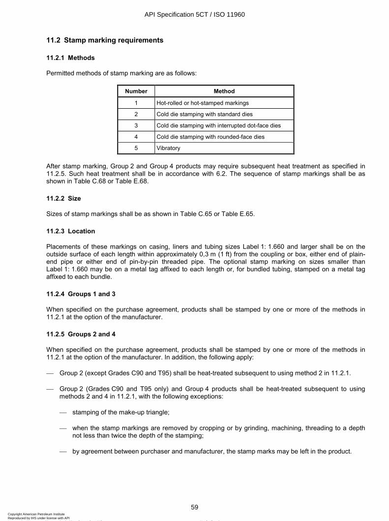
ISO 11960:2004(E)
© ISO 2004 – All rights reserved 59
11.2 Stamp marking requirements
11.2.1 Methods
Permitted methods of stamp marking are as follows:
Number Method
1 Hot-rolled or hot-stamped markings
2 Cold die stamping with standard dies
3 Cold die stamping with interrupted dot-face dies
4 Cold die stamping with rounded-face dies
5 Vibratory
After stamp marking, Group 2 and Group 4 products may require subsequent heat treatment as specified in 11.2.5. Such heat treatment shall be in accordance with 6.2. The sequence of stamp markings shall be as shown in Table C.68 or Table E.68.
11.2.2 Size
Sizes of stamp markings shall be as shown in Table C.65 or Table E.65.
11.2.3 Location
Placements of these markings on casing, liners and tubing sizes Label 1: 1.660 and larger shall be on the outside surface of each length within approximately 0,3 m (1 ft) from the coupling or box, either end of plain-end pipe or either end of pin-by-pin threaded pipe. The optional stamp marking on sizes smaller than Label 1: 1.660 may be on a metal tag affixed to each length or, for bundled tubing, stamped on a metal tag affixed to each bundle.
11.2.4 Groups 1 and 3
When specified on the purchase agreement, products shall be stamped by one or more of the methods in 11.2.1 at the option of the manufacturer.
11.2.5 Groups 2 and 4
When specified on the purchase agreement, products shall be stamped by one or more of the methods in 11.2.1 at the option of the manufacturer. In addition, the following apply:
Group 2 (except Grades C90 and T95) shall be heat-treated subsequent to using method 2 in 11.2.1.
Group 2 (Grades C90 and T95 only) and Group 4 products shall be heat-treated subsequent to using methods 2 and 4 in 11.2.1, with the following exceptions:
stamping of the make-up triangle;
when the stamp markings are removed by cropping or by grinding, machining, threading to a depth not less than twice the depth of the stamping;
by agreement between purchaser and manufacturer, the stamp marks may be left in the product.
API Specification 5CT / ISO 11960
59Copyright American Petroleum Institute Reproduced by IHS under license with API
Not for ResaleNo reproduction or networking permitted without license from IHS
--`,,,```-`-`,,`,,`,`,,`---
ISO 11960:2004(E)
60 © ISO 2004 – All rights reserved
11.2.6 Make-up triangle marking
For buttress casing in all sizes and grades and for round thread casing in sizes Label 1: 16 and larger in Grades H40, J55, K55 and M65, the make-up triangle shall be stamped on the outside of each length on both ends. By agreement between purchaser and manufacturer, the make-up triangle may be replaced with a transverse white paint band 10 mm (3/8 in) wide by 76 mm (3 in) long. To assist in locating the triangle or transverse white paint band on buttress casing, a 25 mm (1 in) wide by 610 mm (24 in) long longitudinal white paint stripe shall be placed adjacent to the triangle or transverse paint band on the field end; additionally, a 25 mm (1 in) wide by 100 mm (4 in) long longitudinal white paint stripe shall be placed adjacent to the triangle or transverse paint band on the mill end.
For Groups 1 and 3, the triangle shall be stamped by method 2 or 4 only.
For Group 2 (Grades C90 and T95 only), the triangle shall be stamped by method 3 only.
For Group 2 (except Grades C90 and T95) and Group 4, the triangle shall be stamped by method 3 or 4 only.
11.3 Stencil marking requirements
Stencil markings shall be placed on the outside surface of each length of pipe, beginning at least 0,6 m (2 ft) from the coupling or box or from either end of plain-end pipe, pin-by-pin threaded pipe or coupling stock. For accessories and pup joints less than 1,8 m (6 ft) in length, the required stencil markings may be placed on a decal attached to the outside surface within 0,3 m (1 ft) of the end. These markings shall be separated by a dash or shall be adequately spaced.
The sequence of stencil markings shall be as specified in Table C.68 or Table E.68, except the thread marking shall be at a location convenient to the manufacturer.
11.4 Colour identification
11.4.1 Colour coding
Each product shall be colour-coded as specified in 11.4.2 to 11.4.6, unless otherwise specified on the purchase agreement.
11.4.2 Product 1,8 m (6 ft) and longer
One or more of the following methods shall be used.
a) For threaded pipe, pup joints and accessories: paint a band encircling the product at a distance not greater than 0,6 m (24 in) from the coupling or internally threaded end.
b) For plain-end or pin-by-pin threaded product: paint a band encircling the product at a distance not greater than 0,6 m (24 in) from either end.
c) Coupling: paint the entire outside surface of the coupling, including the appropriate coupling colour bands.
d) If the pipe is furnished with special-clearance couplings or if the pipe and couplings are of a different grade (except Grades H40, J55 and K55 applied in accordance with 9.2.1), paint both the pipe and couplings as specified in items a), b) and c) above.
11.4.3 Loose couplings
Paint the entire surface of the coupling, including the appropriate colour bands.
API Specification 5CT / ISO 11960
60Copyright American Petroleum Institute Reproduced by IHS under license with API
Not for ResaleNo reproduction or networking permitted without license from IHS
--`,,,```-`-`,,`,,`,`,,`---
ISO 11960:2004(E)
© ISO 2004 – All rights reserved 61
11.4.4 Special-clearance couplings
Paint the coupling using the colours indicative of the steel grade from which the coupling is manufactured, and also paint a black band around the centre.
11.4.5 Pup joints and accessories shorter than 1,8 m (6 ft) in length
Paint the entire surface except the threads, including the appropriate colour bands.
11.4.6 Grade colour-codes
The colour and number of bands for each grade shall be as shown in Table C.66 or Table E.66.
11.5 Thread and end-finish marking — All groups
11.5.1 API thread marking
For manufacturers, thread identification shall be stencilled on casing with round, buttress or extreme-line threads. For threaders, thread identification is required on casing and tubing. This thread identification shall be as shown in Table C.67 or Table E.67.
11.5.2 Unfinished and special end-finish markings
Different marking is required for
a) plain-end pipe furnished either upset or non-upset, or
b) pipe with special end-finish not specified herein but having the body of the pipe manufactured in accordance with the requirements specified herein, or
c) completed couplings and completed accessories furnished with special end-finish not specified herein but which meet all the other requirements specified herein for these products except dimensions.
This marking shall be as shown in Table C.68 or Table E.68.
11.6 Pipe-threader marking requirements — All groups
Pipe threaded by a facility other than the original pipe manufacturer shall be identified, by a stamp or stencil consistent with 11.1, 11.2 and 11.3 adjacent to the threads, with the name or mark of the threader, the specification mark, and size and type of thread as listed in 11.5 and Table C.67 or Table E.67.
The threader shall mark on the body of the pipe the actual hydrostatic test pressure, unless the pipe has been previously tested to the pressure required for the thread as shown in Tables C.45 to C.61 or Tables E.45 to E.61 and marked as specified in Table C.68 or Table E.68.
EXAMPLE For Label 1: 7, Label 2: 29.00, C95, long thread coupling:
Case 1) If the pipe manufacturer produced UF pipe and hydrostatic pressure-tested to 34,5 MPa (5 000 psi) based on the documented design basis of the tester for 177,8 mm (7 in) pipe (see 10.12.3), and marked P34,5 (P5000), then the threader shall pressure-test the pipe to 60,5 MPa (8 800 psi) and mark the pipe in accordance with Figure D.16.
Case 2) If the pipe manufacturer produced UF pipe and hydrostatic pressure-tested to 61,0 MPa (8 900 psi) and marked the pipe P61,0 (P8900), then the threader is not required to pressure-test the pipe or mark the test pressure.
The markings applied to the body of the pipe by the original pipe manufacturer shall not be removed or altered.
Use of the letters “API” to identify or certify that threads on tubular goods comply with API Spec 5B is not permitted.
API Specification 5CT / ISO 11960
61Copyright American Petroleum Institute Reproduced by IHS under license with API
Not for ResaleNo reproduction or networking permitted without license from IHS
--`,,,```-`-`,,`,,`,`,,`---
ISO 11960:2004(E)
62 © ISO 2004 – All rights reserved
12 Coating and protection
12.1 Coatings — All groups
12.1.1 Coatings for protection during transit
Unless otherwise specified in the purchase agreement, pipe and couplings shall be given an external coating for protection from rust while in transit. An attempt should be made to make these coatings smooth, hard to the touch, and with minimum sags. The coating shall be rated to protect the pipe for at least three months. Unless otherwise specified on the purchase agreement, coupling stock shall be supplied without external coating (bare), except for a protective coating that may be applied over the stencil.
If bare pipe or specially coated pipe is desired, the purchase agreement should so state. For special coatings, the purchase agreement should state further whether the coating is to be applied to the full length or whether a certain specific distance from the end is to be left un-coated. Unless otherwise specified, such bare ends are commonly given a coating with oil for protection in transit.
NOTE 13 % Cr tubulars have shown a tendency toward localized pitting corrosion when stored in moist environments. Special precautions during coating, shipping and storage are worthwhile.
12.1.2 Coatings for long-term storage
By agreement between purchaser and manufacturer, protective coatings, internal and external, may be required for pipe for long-term storage to protect against corrosion, especially when stored in a marine environment.
The following points shall apply.
a) The protection shall be effective against corrosion in a marine environment during the long-term storage period defined by the purchaser and manufacturer; minor surface discolouration shall be acceptable.
b) There shall be no need for removal of the protective coating before the running of the tubulars.
c) Correct application of the coating is essential and the following parameters shall be assessed:
dryness of the pipe;
cleanliness of the pipe;
temperature at application;
thickness of the coating film.
12.2 Thread protectors
12.2.1 General
The entity performing the threading shall apply external and internal thread protectors of such design, material and mechanical strength to protect the thread and end of the pipe from damage under normal handling and transportation. External thread protectors shall cover the full length of the thread on the pipe, and internal thread protectors shall cover the equivalent total pipe thread length of the internal thread. Thread protectors shall be of such design and material to inhibit infiltration of dust and water to the threads during transportation and normal storage period. Normal storage period shall be considered as approximately one year. The thread forms in protectors shall be such that the product threads are not damaged by the protectors. Thread protectors are not required for pup joints and accessories provided they are packaged in a manner that protects the threads.
API Specification 5CT / ISO 11960
62Copyright American Petroleum Institute Reproduced by IHS under license with API
Not for ResaleNo reproduction or networking permitted without license from IHS
--`,,,```-`-`,,`,,`,`,,`---
ISO 11960:2004(E)
© ISO 2004 – All rights reserved 63
Additional requirements for PSL-2 and PSL-3 product are given in Annex H.
12.2.2 Material
Protector material shall contain no compounds capable of causing corrosion or promoting adherence of the protectors to the threads and shall be suitable for service temperatures from – 46 ºC to + 66 ºC (– 50 ºF to + 150 ºF).
12.2.3 Grade L80 Types 9Cr and 13Cr
Bare steel thread protectors shall not be used on Grade L80 Types 9Cr and 13Cr tubulars.
12.2.4 Driftable thread protectors
By agreement between purchaser and manufacturer, open-ended, driftable protectors may be supplied. Thread compound shall cover the entire thread and seal surfaces of the connection.
13 Documents
13.1 Electronic media — All groups
A material test report, certificate of compliance or similar document printed from or used in electronic form from an electronic data interchange (EDI) transmission shall be regarded as having the same validity as a counterpart printed in the certifier’s facility. The content of the EDI-transmitted document shall meet the requirements of this International Standard and conform to any existing EDI agreement between purchaser and manufacturer.
13.2 Certification — Groups 1, 2 and 3
A record of heat control tests shall be available to the purchaser.
The manufacturer shall, upon request by the purchaser, furnish to the purchaser a certificate of compliance stating that the material has been manufactured, sampled, tested and inspected in accordance with this International Standard and has been found to meet the requirements.
Additional requirements for PSL-2 and PSL-3 product are given in Annex H.
Where additional information is required, including the results of mechanical testing, the supplementary requirement in A.9 (SR15) shall be specified in the purchase agreement.
13.3 Certification requirements — Grade Q125
A certification shall be provided by the manufacturer for all pipe shipped meeting Group 4 requirements. The requirements in A.9 (SR15) shall apply.
13.4 Retention of records
Tests and inspections requiring retention of records in this International Standard are shown in Table C.69 or Table E.69. Such records shall be retained by the manufacturer and shall be available to the purchaser on request for a period of three years after the date of purchase from the manufacturer.
API Specification 5CT / ISO 11960
63Copyright American Petroleum Institute Reproduced by IHS under license with API
Not for ResaleNo reproduction or networking permitted without license from IHS
--`,,,```-`-`,,`,,`,`,,`---
ISO 11960:2004(E)
64 © ISO 2004 – All rights reserved
14 Minimum facility requirements for various categories of manufacturer
14.1 Pipe mill
A pipe mill shall operate one or more pipe-making facilities capable of producing products as described in Clause 6 of this International Standard. A pipe mill shall also have suitable equipment for, and be responsible for, weighing and marking pipe or coupling stock.
A pipe mill shall also have facilities for conducting all required tests and inspections. Alternatively, and at the option of the pipe mill, any of these tests or inspections may be provided by a subcontractor and may be located off-site. In the event that a subcontractor performs any of these services, the conduct of such inspections and tests shall be controlled and monitored by the pipe mill in accordance with a documented procedure.
14.2 Processor
A processor shall operate heat-treating facilities capable of heat-treating full lengths of pipe or coupling stock. A processor shall also have suitable equipment for, and be responsible for, weighing and marking pipe or coupling stock.
A processor shall also have facilities for conducting all required tests and inspections. Alternatively, and at the option of the processor, any of these tests or inspections may be provided by a subcontractor and may be located off site. In the event that a subcontractor performs any of these services, the conduct of such inspections and tests shall be controlled and monitored by the processor in accordance with a documented procedure.
14.3 Pipe threader
A pipe threader shall operate one or more threading machines capable of threading pipe ends to the dimensions and tolerances specified in API Spec 5B. A threader shall also have suitable equipment for, and be responsible for, markings. A threader shall also have access to master plug and ring gauges, as well as the required working gauges, for each size and type of thread.
A threader shall either have or have access to facilities for:
a) applying couplings to specified make-up,
b) hydrostatic testing the entire length to the pressure required for finished pipe,
c) drift-testing the ends after threading and coupling in accordance with specification requirements, and
d) measuring length.
In the event that a subcontractor performs any of items a), b), c) or d), such services shall be carried out in accordance with documented procedures and shall be controlled and monitored by the threader.
A threader (or a subcontractor) shall not change or alter the markings on the pipe body or certify that the pipe body complies with any ISO/API specification. When subcontract work is performed for the threader, it shall be the responsibility of the threader to ensure that such work complies with the requirements of this International Standard.
14.4 Coupling, pup-joint or accessory manufacturer
A coupling, pup-joint or accessory manufacturer shall operate equipment capable of machining and threading products in accordance with the dimensions and tolerances provided in the applicable specifications. The manufacturer shall also have access to master plug and ring gauges, as well as the required working gauges, for each size and type of thread produced on products marked by the manufacturer in accordance with Clause 11.
API Specification 5CT / ISO 11960
64Copyright American Petroleum Institute Reproduced by IHS under license with API
Not for ResaleNo reproduction or networking permitted without license from IHS
--`,,,```-`-`,,`,,`,`,,`---
ISO 11960:2004(E)
© ISO 2004 – All rights reserved 65
A coupling, pup-joint or accessory manufacturer shall have access to facilities for conducting all other aspects of the manufacturing process for the products (e.g. heat treatment). In the event that subcontractors perform these services, the conduct of inspections and tests shall be controlled and monitored by the coupling, pup-joint or accessory manufacturer in accordance with documented procedures.
Pup-joint manufacturers shall either have or have access to facilities for:
a) hydrostatic testing and
b) drift-testing finished products
in accordance with the requirements of this International Standard.
In the event that a subcontractor performs any of items a) or b), such services shall be carried out in accordance with documented procedures and shall be controlled and monitored by the manufacturer.
Coupling manufacturers shall be capable of inspecting couplings by the magnetic particle inspection or other adequate non-destructive testing method.
A manufacturer (or a subcontractor) shall not change or alter the markings on the pipe body or certify that the pipe body complies with any ISO/API specification. When subcontract work is performed for the manufacturer, it shall be the responsibility of the manufacturer to ensure that such work complies with the requirements of this International Standard.
API Specification 5CT / ISO 11960
65Copyright American Petroleum Institute Reproduced by IHS under license with API
Not for ResaleNo reproduction or networking permitted without license from IHS
--`,,,```-`-`,,`,,`,`,,`---
ISO 11960:2004(E)
66 © ISO 2004 – All rights reserved
Annex A (normative)
Supplementary requirements
A.1 General
This annex describes supplementary requirements that may be specified by the purchaser or agreed between purchaser and manufacturer. These requirements apply only when stated on the purchase agreement.
A.2 SR1 Supplementary non-destructive examination for Grades H40, J55, K55 and N80 Type 1
The specified casing and tubing shall be inspected for imperfections that are greater than 12,5 % of the specified wall thickness or which reduce the net effective wall thickness below 87,5 % of the specified wall thickness.
These imperfections shall be considered defects and shall be given a disposition in accordance with 10.15.16. The inspection(s), including forged upsets, shall be performed to minimum requirements stated in 10.15 for Grades N80Q, M65, L80 and C95.
A.3 SR2 Supplementary non-destructive examination for Grades H40, J55, K55, N80 Type 1, N80Q, M65, L80, C95 and P110 to A.10 (SR16)
The specified casing and tubing shall be inspected for imperfections that are greater than 5 % of the specified wall thickness or which reduce the net effective wall thickness below 87,5 % of the specified wall thickness. These imperfections shall be considered defects and shall be given a disposition in accordance with 10.15.16. The inspection(s), including forged upsets, shall be performed to the minimum requirements stated in 10.15 for Grade P110.
A.4 SR9 Coupling blanks — Grade Q125 only
A.4.1 SR9.1 Coupling blank size
Coupling blank dimensions shall be adequate to yield a fully machined cylinder with uniform wall thickness with an outside diameter, inside diameter and length as specified on the purchase agreement. The coupling blanks shall be provided fully machined by the manufacturer only when specified on the purchase agreement.
A.4.2 SR9.2 Dimensional tolerances
For fully machined coupling blanks, the tolerance on outside diameter shall be 2,380 mm+ ( 3 / 32
0 in+ ) and the tolerance on the inside diameter shall be 0
2,38 mm- ( 03 / 32 in- ), unless otherwise agreed upon between
purchaser and manufacturer.
API Specification 5CT / ISO 11960
66Copyright American Petroleum Institute Reproduced by IHS under license with API
Not for ResaleNo reproduction or networking permitted without license from IHS
--`,,,```-`-`,,`,,`,`,,`---
ISO 11960:2004(E)
© ISO 2004 – All rights reserved 67
Coupling blanks ordered with as-rolled outside diameter surface shall have an outside diameter tolerance of ± 1 %, but not greater than 3,18
1,59 mm+- ( 1/ 8
1/16 in+- ).
A.4.3 SR9.3 Imperfections
Coupling blanks that will not be fully machined by either the manufacturer or the purchaser shall be inspected and meet the same requirements as finished couplings. Coupling blanks that will be fully machined by either the manufacturer or the purchaser may have imperfections on the as-rolled surface; however, the machined surface shall meet the surface inspection criteria of 9.14 and be to the specified dimensions.
A.4.4 SR9.4 Marking
All coupling blanks meeting the requirements of A.4 (SR9) shall be marked as specified in Table C.68 or E.68 or Table C.81 or E.81.
A.5 SR10 Upset casing — Grade Q125 only
A.5.1 SR10.1 Dimensions
Grade Q125 casing shall be provided with upset end(s). Dimensions of the upset, if other than extreme-line (including tolerances), shall be specified on the purchase agreement.
A.5.2 SR10.2 Material properties
Tensile, impact and hardness properties of the pipe and upset shall comply with the requirements of Clause 7. The allowable hardness variation of the upset shall be based on the nominal wall thickness of the upset specified on the purchase agreement. The tensile test specimens for the upset shall be the largest round specimen feasible. The size to be used shall be agreed by the purchaser and manufacturer prior to testing.
A.5.3 SR10.3 Heat treatment
Upset pipe shall be heat-treated full length after upsetting.
A.5.4 SR10.4 Other testing considerations
The frequency of testing, re-test provisions, identification, etc., for both the pipe body and the upset material shall be as specified in Clause 10.
A.5.5 SR10.5 End area inspection
The outside and inside surfaces of the ends of upset pipe shall be inspected after final heat treatment and before threading for transverse and longitudinal defects by the magnetic particle method.
A.5.6 SR10.6 Machined surface inspection of extreme-line casing
A.5.6.1 SR10.6.1 Requirements for inspection
The machined surface of extreme-line casing shall be visually examined for imperfections. The maximum permissible depth of imperfection measured from the surface shall be as specified in A.5.6.2 to A.5.6.4.
API Specification 5CT / ISO 11960
67Copyright American Petroleum Institute Reproduced by IHS under license with API
Not for ResaleNo reproduction or networking permitted without license from IHS
--`,,,```-`-`,,`,,`,`,,`---
ISO 11960:2004(E)
68 © ISO 2004 – All rights reserved
A.5.6.2 SR10.6.2 Pin end
Location of imperfection Permissible depth External surface: 12,5 % of specified pipe body wall thickness
Internal surface:
From end of pipe to plane of external shoulder (bored): 0,38 mm (0.015 in)
From plane of external shoulder to upset run-out: 12,5 % of specified pipe body wall thickness
A.5.6.3 SR10.6.3 Box end
Location of imperfection Permissible depth
External surface:
From the end of the pipe to a plane 120,60 mm (4¾ in) from the end of pipe Label 1: 7-5/8 and smaller, and 165,10 mm (6½ in) from the end of pipe Label 1: 8-5/8 and larger: 0,25 mm (0.010 in)
From a plane 120,60 mm (4¾ in) from the end for pipe Label 1: 7-5/8 and smaller and 165,10 mm (6½ in) from the end for pipe Label 1: 8-5/8 and larger, to the upset run-out: 12,5 % of specified pipe body wall thickness
Internal surface: 12,5 % of specified pipe body wall thickness
A.5.6.4 SR10.6.4
All machined surfaces of the box shall be free of seams and cracks. All threads and seals shall be free of any imperfections which break the continuity.
A.5.6.5 SR10.6.5
The minimum wall thickness in the upset run-out interval, see Figure D.8, shall not be less than 87,5 % of the specified pipe body wall thickness.
A.5.6.6 SR10.7 Dimensions and masses
Dimensions and masses for extreme-line casing are shown in Tables C.24 and C.26 or Tables E.24 and E.26.
A.6 SR11 Electric-welded casing, tubing and pup joints, Grade P110 and electric-welded casing and pup joints, Grade Q125
A.6.1 SR11.1 General
Casing (Grades P110 and Q125) and tubing (Grade P110) may be produced by the electric-weld process only when detailed quality control provisions are jointly agreed by purchaser and manufacturer prior to the manufacture of the pipe. Tensile, impact and hardness testing shall be performed as frequently as required for seamless casing.
A.6.2 SR11.2 Flattening test frequency
A.6.2.1 SR11.2.1 — Grade P110
The flattening test frequency shall be as specified in 10.5.2.
API Specification 5CT / ISO 11960
68Copyright American Petroleum Institute Reproduced by IHS under license with API
Not for ResaleNo reproduction or networking permitted without license from IHS
--`,,,```-`-`,,`,,`,`,,`---
ISO 11960:2004(E)
© ISO 2004 – All rights reserved 69
A.6.2.2 SR11.2.2 — Grade Q125
Flattening tests shall be performed on each end of each length of pipe. On one end, flattening tests shall be made with weld at 6 o'clock and on the other end with weld at 3 o'clock. All inspection shall be performed and imperfections removed (cut-backs made) prior to removal of flattening test specimens.
A.6.3 SR11.3 Flattening test procedures
A.6.3.1 SR11.3.1 — Grade P110
The test specimens shall be flattened as specified in 10.5.3, 10.5.5 and 10.5.7.
A.6.3.2 SR11.3.2 — Grade Q125
Test specimens shall be rings or crop ends not less than 63,5 mm (2½ in) long, cut from each end of each length of pipe. Precautions shall be taken so that the test specimens can be identified with respect to the lengths of pipe from which they are cut. Flattening tests shall be conducted with the weld line located at the 6 o'clock or 3 o'clock position. Minimum acceptable flattening without cracking at any location shall be as shown in Table C.70 (SR11.1) or Table E.70 (SR11.1) or 0,85D, whichever requires the greater flattening.
No cracks or breaks shall occur anywhere in the specimen until the distance between the plates is less than that specified above; nor shall evidence of poor texture, incomplete fusion in the weld or laminations develop during the entire flattening process.
A.6.4 SR11.4 Other material properties
Electric-welded pipe shall meet the same tensile, impact and hardness requirements as seamless pipe. The impact test specimen shall be machined with the notch at the weld line. The requirements of Clause 10 (for seamless pipe) shall also apply to electric-welded pipe.
A.6.5 SR11.5 Inspection and rejection
A.6.5.1 SR11.5.1 Non-weld area inspection
The pipe body shall be inspected in the same manner as the seamless product as specified in Clause 10.
A.6.5.2 SR11.5.2 Non-destructive examination of weld seam
The weld seam of pipe (except upset ends) furnished to this International Standard shall be inspected non-destructively full length (100 %) by ultrasonic methods. The inspection shall be performed after all heat treatment and any subsequent rotary straightening operation. Pipe upsets shall be inspected as specified in 10.15.13.
A.6.5.3 SR11.5.3 Equipment
Any equipment utilizing the ultrasonic principles capable of continuous and uninterrupted inspection of the weld seam shall be used. The equipment shall be checked with an applicable reference standard as described in A.6.5.4 (SR11.5.4) at least once every working shift to demonstrate the effectiveness of the inspection equipment and procedures. The equipment shall be adjusted to produce well-defined indications when the reference standard is scanned by the inspection unit in a manner simulating the inspection of the product, and shall be capable of inspecting 1,6 mm (1/16 in) on either side of the weld line for the entire wall thickness.
A.6.5.4 SR11.5.4 Reference standards
A reference standard having the same specified diameter and thickness as the product being inspected shall be used to demonstrate the effectiveness of the inspection equipment and procedures at least once every working shift. The reference standard may be of any convenient length as determined by the manufacturer. It
API Specification 5CT / ISO 11960
69Copyright American Petroleum Institute Reproduced by IHS under license with API
Not for ResaleNo reproduction or networking permitted without license from IHS
--`,,,```-`-`,,`,,`,`,,`---
ISO 11960:2004(E)
70 © ISO 2004 – All rights reserved
shall be scanned by the inspection unit in a manner simulating the inspection of the product. For ultrasonic inspection, the reference standard shall contain two notches, one on the outer and one on the inner surface as specified in Figure D.17 (SR 11.1). The 1,6 mm (1/16 in) diameter hole shall be drilled radially through the wall of the reference standard. The inspection equipment shall be adjusted to produce a well-defined indication when the reference standard is scanned by the inspection unit.
A.6.5.5 SR11.5.5 Rejection limits
Any imperfection that produces a signal greater than or equal to the signal received from the reference standard shall be considered a defect unless it can be demonstrated by the manufacturer that the imperfection does not exceed the provisions of A.6.5.6 (SR11.5.6).
A.6.5.6 SR11.5.6 Disposition
Imperfections revealed by magnetic particle inspection and determined to be greater in depth than 5 % but not greater than 12,5 % of the specified wall thickness shall be removed by grinding or machining, or the pipe shall be rejected. All imperfections classified as defects by the ultrasonic or electromagnetic equipment which do not exceed 12,5 % of the specified wall thickness in depth shall be removed by grinding or machining, or the pipe shall be rejected.
Pipe with defects whose removal requires grinding or machining to a depth in excess of 12,5 % of the specified wall thickness shall be disposed of in accordance with 10.15.16. Where grinding or machining is done, generous radii shall be used to prevent abrupt changes in wall thickness, and such areas shall be re-inspected by one of the non-destructive inspection methods specified herein to verify complete removal of the defect.
A.7 SR12 Statistical impact testing
A.7.1 SR12.1 General
This supplementary requirement specifies a statistical approach to testing. It is applicable only to those items that are accepted or rejected on a lot basis. The frequency of testing is based on standard statistical techniques for properties that have a normal distribution and where the standard deviation for a particular manufacturer, size, chemistry, etc., is not well established. The statistical acceptance and rejection procedures are required only for impact properties; however, the tensile and hardness properties shall be measured on all tubulars where impact samples are taken. Tensile, impact and hardness requirements are as required in Clause 7. The basis of the testing procedure is explained in Note 1 in A.7.5 (SR12.5).
A.7.2 SR12.2 Frequency of testing
Every length of casing shall be uniquely numbered. This number shall be used for all subsequent identification. Tensile, impact and hardness test specimens for casing shall be taken at the same frequency from locations shown in Figure D.10. The sample size for each lot of casing shall be selected by the manufacturer from Table C.71 (SR12.1) or Table E.71 (SR12.1).
The factor F shown for the sample size selected shall be used in A.7.4 (SR12.4) to determine acceptance or rejection of a lot based on the applicable transverse or longitudinal impact requirements. The number of samples is not dependent on the size of the lot. The lengths for testing shall be selected at random, provided the selection procedure provides samples representing at least the start and end of the heat treat cycle and both ends of the tubes (approximately 50 % each end).
By agreement between purchaser and manufacturer, a factor F of 3,090 may be used in lieu of the values given in Table C.71 (SR12.1) or Table E.71 (SR12.1) provided the standard deviation of the new lot of material is consistent with past experience.
API Specification 5CT / ISO 11960
70Copyright American Petroleum Institute Reproduced by IHS under license with API
Not for ResaleNo reproduction or networking permitted without license from IHS
--`,,,```-`-`,,`,,`,`,,`---
ISO 11960:2004(E)
© ISO 2004 – All rights reserved 71
A.7.3 SR12.3 Re-test
If a tensile test specimen fails to conform to the specified requirements, the manufacturer shall make additional tests on each end of the tubular. If an impact test specimen fails to conform to the specified requirements, the manufacturer shall follow the re-test provisions of 10.7.7, 10.7.8 and 10.7.9 (as applicable). If a hardness test specimen fails to conform to the specified requirements, the manufacturer shall follow the re-test provisions of 10.6.10, 10.6.11, 10.6.12 and 10.6.13 (as applicable).
If any pipe is rejected from a lot due to failure to demonstrate acceptable tensile, impact or hardness requirements, then the pipe tempered immediately before and after the length rejected shall be tested on the same end as the pipe that was rejected. If one or both of the additional test lengths fail to conform to the specified requirements, the manufacturer may elect to test individually all remaining lengths in the lot, in which case determinations are required only for the particular requirement with which the specimens failed to comply in the preceding tests (i.e. a lot which meets the hardness and impact criteria but which has been rejected due to low elongation shall be re-tested to verify tensile properties). Specimens for all re-tests shall be taken in the same manner as the initial test specimen. Tubulars that fail to meet the requirements of Clause 7 shall be rejected.
A.7.4 SR12.4 Acceptable impact energy for any lot of casing
Subsequent to impact testing, the mean and standard deviation shall be calculated for the average transverse impact energy values. This calculation shall be made including the data for all lengths rejected due to low impact energy. The lot minimum impact energy Smin shall then be estimated (based on the sample data) as follows:
min lotS S F σ= − ⋅
where
S is the test lot mean impact energy;
F is the factor determined from Table C.71 (SR12.1) or Table E.71 (SR12.1);
σ lot is the lot standard deviation.
A.7.5 SR12.5 Lot acceptance/rejection
The lot shall be accepted provided Smin is greater than or equal to CV determined in 7.4, 7.5 or 7.6 (as applicable). If Smin is less than CV, then additional random joints may be selected for testing. The S , σ lot, and Smin shall be determined as above based on all the data and the new F value. The new Smin shall exceed CV determined in 7.4, 7.5 or 7.6, otherwise the lot shall be rejected. Additional random samples may be taken from additional pipes as many times as necessary. If the casing is rejected as a lot, then each length may be tested to demonstrate that it meets the minimum impact energy requirements of 7.4, 7.5 or 7.6 (as applicable).
NOTE 1 Explanation of testing frequency [see A.7.2 (SR12.2)]: Since a string of casing consists of more than one length of pipe, analysis should consider the probability that the string includes one or more lengths whose impact properties do not meet the desired minimum.
Table C.72 (SR12.2) or Table E.72 (SR12.2) gives the probability of a pipe string of 100 lengths including one or more unacceptable lengths. If the probability of any length being unacceptable is 1 in 1 000 then there is a 10 % chance that the pipe string will include one or more unacceptable lengths. If the probability of any length being unacceptable is 1 in 10 000, then there is a 1 % chance that the pipe string will include one or more unacceptable lengths. The statistical model used for the examination frequency is designed to yield an individual tube reliability of 99,9 %. A typical confidence limit of 95 % is used with a tolerance interval approach, since the standard deviation is neither well established nor expected to be consistent for all manufacturers, product sizes, heat treatments, chemistries, etc.
The tolerance interval approach assumes that the standard deviation is not well known. The factor F is large because it includes variations that can be expected in the standard deviation. For example, if the impact requirement is 27 J (20 ft⋅lb), 5 lengths are sampled and the standard deviation is determined to be 4,1 then the factor F is 7,501 (7.501). For the lot to
API Specification 5CT / ISO 11960
71Copyright American Petroleum Institute Reproduced by IHS under license with API
Not for ResaleNo reproduction or networking permitted without license from IHS
--`,,,```-`-`,,`,,`,`,,`---
ISO 11960:2004(E)
72 © ISO 2004 – All rights reserved
be acceptable, the average transverse impact value shall exceed 27 + (7,501 × 4,1) or 58 J [20 + (7.501 × 3.0) or 43 ft⋅lb]. If 10 lengths had been sampled and the standard deviation was still 4,1, then the average impact value shall exceed 27 + (5,203 × 4,1) or 48 J [20 + (5.203 × 3.0) or 36 ft⋅lb]. If the standard deviation from a mill is well known, then the factor F is taken for an infinite number of samples of F = 3,090 (3.090). Assuming the standard deviation for an infinite number of samples from a given size tubular and one mill is 4,1, then the average impact value shall exceed 27 + (3,090 × 4,1) or 40 J [20 + (3.090 × 3.0) or 29 ft⋅lb]. The method is applicable to both SI and USC units.
NOTE 2 The procedure in A.7 (SR 12) is taken from reference [5]. Table C.71 (SR12.1) or Table E.71 (SR12.1) is taken from Table A-7 in reference [5]. The procedure to calculate the mean and standard deviation for the average transverse impact energy for the lot can also be found in reference [5], Chapter 1, Clause 1-6.
A.8 SR13 Seal-ring couplings
A.8.1 SR13.1 Seal-ring groove
Seal-ring couplings shall be grooved in accordance with dimensions and tolerance specified in Figures D.18 (SR13.1) to D.21 (SR13.4). Grooves may be cut before or after threading at manufacturer's option. Grooves and threads shall be free of fins, wickers and ribbons that are loose or can become loose and fold into the thread form. Couplings shall be inspected after final machining of the groove. The inspection shall be by the wet fluorescent magnetic particle method, using a circumferentially oriented magnetic field, or by another non-destructive method of equal sensitivity as demonstrated to the purchaser. The inspection shall encompass both the inside and outside surfaces. The inspection shall exclude the dry magnetic particle method.
NOTE The seal-ring groove dimensions are not the same as those used historically and may not be interchangeable with them.
A.8.2 SR13.2 Non-metallic ring
Dimensions and tolerances of non-metallic rings for seal-ring couplings shall be as specified in Figures D.18 (SR13.1) to D.21 (SR13.4). Rings shall be made from virgin polytetrafluoroethylene (PTFE) with 25 % fibreglass filler. The starting PTFE shall be free of filler.
Additional requirements for PSL-2 and PSL-3 product are given in Annex H.
NOTE The seal-ring dimensions are not the same as those used historically and may not be interchangeable with them.
A.8.3 SR13.3 Marking
All couplings that meet the requirements of A.8 (SR13) shall be marked “S13”.
A.9 SR15 Test certificates
A.9.1 SR15.1
The manufacturer shall provide the following data, as applicable, for each item for which this Supplementary Requirement is specified on the purchase agreement. The manufacturer's certificate shall cite this International Standard, and revision date thereof, to which the product was manufactured.
a) SR15.1.1
Specified diameter, wall thickness, grade, process of manufacture and type of heat treatment.
b) SR.15.1.2
The minimum tempering temperature allowed by the documented heat treatment procedure for each lot of quenched and tempered or normalized and tempered casing and tubing (except coupling stock).
API Specification 5CT / ISO 11960
72Copyright American Petroleum Institute Reproduced by IHS under license with API
Not for ResaleNo reproduction or networking permitted without license from IHS
--`,,,```-`-`,,`,,`,`,,`---
ISO 11960:2004(E)
© ISO 2004 – All rights reserved 73
c) SR15.1.3
Chemical analyses (heat, product, control, and re-check) showing the mass fraction, expressed as a percent, of all elements whose limits or reporting requirements are set in this International Standard.
d) SR15.1.4
Test data for all tensile tests required by this International Standard, including yield strength, ultimate tensile strength, elongation. The type, size and orientation of specimens shall be shown.
If elongation is recorded or reported, the record or report shall show the nominal width of the test specimen when strip specimens are used, the diameter and gauge length when round-bar specimens are used, or it shall state when full-section specimens are used.
e) SR15.1.5
Impact test results [including the test criteria, and the size, location and orientation of the test specimen, the nominal test temperature (i.e. the actual test temperature, including the sub-size temperature reduction if applicable), the absorbed energy measured for each test specimen, the percent shear area, and the average absorbed energy for each test], where such testing is required by this International Standard.
f) SR15.1.6
Hardness test results (including Rockwell hardness numbers and mean hardness numbers, test type and criterion, and specimen location and orientation) where such testing is required.
g) SR15.1.7
The grain size and the test method used to determine the grain size.
h) SR15.1.8
Minimum hydrostatic test pressure and duration.
i) SR15.1.9
For welded pipe for which NDE of the weld seam is required by this International Standard, the method of NDE employed (ultrasonic, electromagnetic and/or magnetic particle) and the type of reference standard.
j) SR15.1.10
For seamless product for which NDE is specified by the purchaser (either in the body of this International Standard, in the Supplementary Requirements, or in the purchase agreement), the method of inspection employed (ultrasonic, electromagnetic, or magnetic particle) and the type and size of the reference standard used.
k) SR15.1.11
For electric-welded pipe, the minimum temperature for heat treatment of the weld seam. If such heat treatment is not performed, “No Seam Heat Treatment” shall be stated on the certificate.
l) SR15.1.12
Results of any supplemental testing required by the purchaser.
API Specification 5CT / ISO 11960
73Copyright American Petroleum Institute Reproduced by IHS under license with API
Not for ResaleNo reproduction or networking permitted without license from IHS
--`,,,```-`-`,,`,,`,`,,`---
ISO 11960:2004(E)
74 © ISO 2004 – All rights reserved
A.9.2 SR15.2
The manufacturer shall establish and follow procedures for maintaining heat and lot identity of all product covered by this Supplementary Requirement. The procedures shall provide means for tracing the product to the proper heat and lot, and to all applicable chemical and mechanical test results.
A.10 SR 16 Impact testing (Charpy V-notch) for pipe
A.10.1 SR16.1 Testing requirements
When A.10 (SR16) is specified on the purchase agreement for Group 1 Grade N80Q, Group 2 (except M65), and Group 3, the testing provisions of 10.7, which are optional for the manufacturer in accordance with 7.5.6, become mandatory. When A.10 (SR16) is specified on the purchase agreement for Group 1 Grades H40, J55, K55 and N80 Type 1, the requirements in A.10.2 are mandatory.
A.10.2 SR16.2 Charpy V-notch test — General requirements
A.10.2.1 General
A test shall consist of three specimens from a pipe, taken from each lot in accordance with 10.2. The average result from the three impact specimens shall equal or exceed the absorbed energy requirement specified in A.10.3 (SR16.3). In addition, not more than one impact specimen shall exhibit an absorbed energy below the absorbed energy requirement, and in no case shall an individual impact specimen exhibit an absorbed energy below two-thirds of the absorbed energy requirement.
A.10.2.2 SR16.2.1 Specimen size
Table C.73 (SR16.1) or Table E.73 (SR16.1) provides the calculated wall thickness required to machine full-size, ¾-size, and ½-size transverse impact test specimens. Table C.74 (SR16.2) or Table E.74 (SR16.2) provides the same information for longitudinal impact test specimens. The impact test specimen size that shall be selected from Table C.73 (SR16.1) or Table C.74 (SR16.2) or Table E.73 (SR16.1) or Table E.74 (SR16.2) is the largest impact test specimen having a calculated wall thickness that is less than the specified wall thickness for the pipe tested.
When the use of full-size (10 mm × 10 mm) transverse test specimens is not possible, the largest possible sub-size transverse test specimen listed in Table C.75 (SR16.3) or Table E.75 (SR16.3) shall be used. When it is not possible [or allowed in accordance with A.10.2.4 (SR16.2.4)] to test using any of these transverse test specimens, the largest possible longitudinal test specimen listed in Table C.75 (SR16.3) or Table E.75 (SR16.3) shall be used.
When the outside diameter or wall thickness precludes machining longitudinal impact test specimens ½-size or larger, the pipe need not be tested; however, the manufacturer shall use a chemical composition and processing that is documented and demonstrated to result in impact energy absorption in excess of the minimum specified requirement.
A.10.2.3 SR16.2.2 Specimen allowance for outside diameter curvature
The surface of the finish-machinedtransverse test specimens may contain the outside diameter curvature of the original tubular product provided that the requirements of Figure D.22 (SR16.1) are met. These specimens shall be used only to permit the use of a transverse specimen of maximum thickness.
A.10.2.4 SR16.2.3 Hierarchy of test specimens
The hierarchy of test specimen orientation and size is as specified in Table C.76 (SR16.4) or Table E.76 (SR16.4).
API Specification 5CT / ISO 11960
74Copyright American Petroleum Institute Reproduced by IHS under license with API
Not for ResaleNo reproduction or networking permitted without license from IHS
--`,,,```-`-`,,`,,`,`,,`---
ISO 11960:2004(E)
© ISO 2004 – All rights reserved 75
A.10.2.5 SR16.2.4 Alternative-size impact test specimens
At the manufacturer's option, alternative-size impact test specimens, listed in Table C.75 (SR16.3) or Table E.75 (SR16.3), may be used in lieu of the minimum size specified in the tables referenced in A.10.2.1 (SR16.2.1). However, the alternative test specimen size shall be higher on the hierarchy table [Table C.76 (SR16.4) or Table E.76 (SR16.4)] than the specified size, and the absorbed energy requirement shall be adjusted consistent with the impact specimen orientation and size selected.
A.10.2.6 SR16.2.5 Absorbed energy requirement for sub-size specimens
The minimum CVN absorbed energy requirement, CV, for sub-size test specimens shall be that specified for a full-size test specimen multiplied by the reduction factor in Table C.75 (SR16.3) or Table E.75 (SR16.3); however, in no event shall a sub-size test specimen be used if the reduced absorbed energy requirement is less than 11 J (8 ft⋅lb).
A.10.3 SR16.3 Charpy V-notch test — Impact requirements for pipe and for externally threaded accessory material
A.10.3.1 SR16.3.1 Grade H40 only
The minimum full-size transverse CVN absorbed energy requirement, CV, is 16 J (12 ft⋅lb) for all wall thicknesses.
The minimum full-size longitudinal CVN absorbed energy requirement, CV, is 20 J (15 ft⋅lb) for all wall thicknesses.
A.10.3.2 SR16.3.2 Grades J55 and K55 only
The minimum full-size transverse CVN absorbed energy requirement, CV, is 20 J (15 ft⋅lb) for all wall thicknesses.
The minimum full-size longitudinal CVN absorbed energy requirement, CV, is 27 J (20 ft⋅lb) for all wall thicknesses.
A.10.3.3 SR16.3.3 Grade N80 Type 1
The minimum CVN absorbed energy requirement for full-size test specimens for pipe is provided in Table C.77 (SR16.5) or Table C.78 (SR16.6), or Table E.77 (SR16.5) or Table E.78 (SR16.6).
The requirements are calculated based on the equations given below, where:
YSmin is the minimum specified yield strength, in megapascals (552 MPa) [thousands of pounds per square inch (80 ksi)], and
t is the specified wall thickness, in millimetres (inches).
Unit system Transverse requirement CV
Longitudinal requirement CV
SI units, joules YSmin (0,001 18 t + 0,012 59)
or 14 J whichever is greater
(Table C.77)
YSmin (0,002 36 t + 0,025 18)
or 27 J whichever is greater
(Table C.78)
USC units, foot pounds YSmin (0.152 t + 0.064)
or 10 ft⋅lb whichever is greater
(Table E.77)
YSmin (0.304 t + 0.128)
or 20 ft⋅lb whichever is greater
(Table E.78)
API Specification 5CT / ISO 11960
75Copyright American Petroleum Institute Reproduced by IHS under license with API
Not for ResaleNo reproduction or networking permitted without license from IHS
--`,,,```-`-`,,`,,`,`,,`---
ISO 11960:2004(E)
76 © ISO 2004 – All rights reserved
A.10.4 SR16.4 Accessories with integral joint API tubing connections and extreme line casing connections
The requirements in 7.4 shall apply. The critical thickness shall be as specified in 7.3.2 and 7.6.6.
A.10.5 SR16.5 Accessories with internal special end-finish connections that do not have thread interference
The requirements in A.10.3 (SR16.3) apply. The critical thickness shall be as specified in 7.3.2 and 7.6.6.
A.10.6 SR16.6 Impact test procedures
A.10.6.1 SR16.6.1 General procedures
CVN Type A impact tests shall be conducted as specified in ASTM A370 and ASTM E23. When transverse impact test specimens are used for EW pipe, the test specimen shall be machined with the notch at the weld line. When longitudinal impact test specimens are used for EW pipe, the test specimens shall be taken from a location approximately 90∞ from the weld. Impact test specimens shall not be machined from flattened tubulars.
A.10.6.2 SR16.6.2 Specimen orientation
Specimen orientation shall be in accordance with Figure D.12.
A.10.6.3 SR16.6.3 Test temperature
The test temperature for full-size test specimens shall be specified by the purchaser as:
a) + 21 ºC (+ 70 ºF), or
b) 0 ºC (+ 32 ºF), or
c) – 10 ºC (+ 14 ºF), or
d) other temperature as specified on the purchase agreement.
The tolerance on the test temperature for full-size test specimens shall be ± 3 ºC (± 5 ºF).
The test temperature shall be reduced as specified in A.10.6.5 (SR16.5.5) for Grades H40, J55 and K55 when sub-size test specimens are required.
Additional requirements for PSL-2 and PSL-3 product are given in Annex H.
NOTE The Grades H40, J55 and K55 are low strength steels considered to be loading-rate sensitive. Increasing the loading rate from that generally occurring in the use of the product to the loading rate occurring in the impact testing of the Charpy specimens results in shifting the fracture transition to higher temperatures. Thus, the fracture transition behaviour of the product would be expected to occur at temperatures lower than those obtained with Charpy testing. In most applications, testing Grades H40, J55 and K55 at + 21 ºC (+ 70 ºF) and higher strength grades at 0 ºC (+ 32 ºF) should be adequate. If the pipe will be handled at temperatures below – 18 ºC (0 ºF), a lower impact test temperature may be appropriate.
A.10.6.4 SR16.6.4 Defective specimens
Any test specimen that shows defective preparation or material imperfections unrelated to the intent of the test, whether observed before or after testing, may be discarded and be replaced by another specimen from the same length of pipe. Specimens shall not be judged defective simply because they failed to exhibit the minimum absorbed energy requirement.
API Specification 5CT / ISO 11960
76Copyright American Petroleum Institute Reproduced by IHS under license with API
Not for ResaleNo reproduction or networking permitted without license from IHS
--`,,,```-`-`,,`,,`,`,,`---
ISO 11960:2004(E)
© ISO 2004 – All rights reserved 77
A.10.6.5 SR16.6.5 Sub-size test temperature reduction — Grades H40, J55 and K55 only
A test temperature reduction may be required when sub-size test specimens are used. The test temperature reduction depends on the thickness of the pipe and the size of the impact test specimen.
The test temperature reduction specified in Table C.79 (SR16.7) or Table E.79 (SR 16.7) shall be used when applicable.
A.10.6.6 SR16.6.6 Frequency of testing
One test shall be made on one pipe from each lot.
A.10.6.7 SR16.6.7 Reject of a pipe or accessory
If the results from more than one specimen are below the specified minimum absorbed energy requirement or if one value is below two-thirds of the specified minimum absorbed energy requirement, a re-test shall be carried out on three additional specimens from the same pipe. The impact energy of each of the re-test specimens shall equal or exceed the specified minimum absorbed energy requirement or the pipe shall be rejected.
A.10.6.8 SR16.6.8 Replacement of a reject pipe or accessory
If the results of a test do not meet the requirements of A.10.3 (SR16.3), A.10.4 (SR16.4) or A.10.5 (SR16.5) as applicable and do not qualify for re-testing accordance with A.10.6.7 (SR16.6.7), then an additional three test specimens shall be removed from each of three additional pipes from the lot. If all the additional pipes tested conform to the requirements, then the lot shall be qualified except for the pipe that was initially rejected. If one or more of the additional test pipes fail to conform to the specified requirements, the manufacturer may elect to test individually the remaining pipe in the lot or re-heat-treat and test the lot as a new lot.
A.10.6.9 SR16.6.9 Rounding procedures
For purposes of determining conformance with these requirements, an observed value shall be rounded to the nearest whole number in accordance with the rounding method of ISO 31-0 or ASTM E29. Further, limiting values as specified or calculated shall be expressed as whole numbers, rounded if necessary.
A.10.7 SR16.7 Reporting
The size and orientation of the test specimen (i.e. full-size, ¾-size or ½-size), the actual test temperature (i.e. specified temperature less the test temperature reduction that may be applicable for Grades H40, J55, and K55), the results of the individual specimens (i.e. the impact energy absorption and the percentage shear), and the average absorbed energy shall be reported to the purchaser.
A.10.8 SR16.8 Marking
Pipe tested in accordance with this supplementary requirement shall be marked to indicate A.10 (SR16), the minimum full-size energy absorption requirement, and the specified test temperature (i.e. not including the test temperature reduction that may be applicable for Grades H40, J55 and K55) preceded by a positive or negative sign. This marking shall be paint-stencilled after the grade designation.
Example for SI units: S16-20-10C
Example for USC units: S16-15+14F
API Specification 5CT / ISO 11960
77Copyright American Petroleum Institute Reproduced by IHS under license with API
Not for ResaleNo reproduction or networking permitted without license from IHS
--`,,,```-`-`,,`,,`,`,,`---

ISO 11960:2004(E)
78 © ISO 2004 – All rights reserved
A.11 SR22 Enhanced leak resistance LTC
A.11.1 General
By agreement between purchaser and manufacturer, the Supplementary Requirements for enhanced leak resistance LTC in SR22 shall apply. It should be noted that the SR22 product is fully interchangeable with standard API LTC connections. However, the SR22 design criteria concerning leak resistance shall not apply for such mixed product.
Liquid metal embrittlement may result if thread compound containing lead is used with tin-plated couplings at elevated temperatures for some materials. Use of thread compounds containing lead in applications involving temperatures in excess of 135 ºC (275 ºF) is cautioned.
NOTE The application of API connections or pipe at elevated temperature or in sour service conditions is beyond the scope of this International Standard.
A.11.2 SR22 Enhanced leak resistance
A.11.2.1 SR22.1
Casings and couplings shall be furnished with enhanced leak resistance LTC connections in accordance with the requirements specified in API Spec 5B SR22 for dimensions, inspection and coupling thread coatings.
A.11.2.2 SR22.2.a Die stamp-marking the end of the pipe
An equilateral triangle die stamp 6,35 mm (¼ in) high shall be placed at a distance of L9 from each end of each pipe using Method 3, 4 or 5 of 11.2.1. See Figure D.24 SR22-1.
A.11.2.3 SR22.2.b Paint-marking the end of the pipe
High-visibility green paint marks shall be applied on the field end of each pipe. See Figure D.24 SR22-1.
A.11.2.4 SR22.2.c Die stamp-marking the couplings
All couplings shall be marked “S22” using Method 3 or 5 of 11.2.1.
A.11.2.5 SR22.2.d Colour-banding the couplings
Couplings shall be colour-banded with the colour(s) indicative of the steel grade from which the couplings are manufactured, and shall also be painted with a high-visibility green band around the outside surface near one end of the coupling.
A.11.2.6 SR22.3 Optional tapered bore requirement for casing with special drift requirements
For casing ordered with a drift mandrel of diameter larger than standard (see 8.10), the manufacturer may drift or bore along the inside diameter of the ends of the pipe. This option requires either of the following treatments for both ends of the pipe:
a) to be drifted with a special end drift with a minimum diameter in accordance with the “special end drift diameter” column of Option 1 in Figure D.25 (SR22.2). The drift shall be inserted a distance equal to or greater than L9. Pipe ends that are too small to accept the special end drift shall be bored along the inside diameter in accordance with b) below.
b) to be finished with a tapered bore along the inside diameter with a taper between 2º and 15º, the maximum diameter of the machined surface at the end of the pipe “(chamfer diameter d0)”, and the angle of the tapered bore shall be in accordance with Option 2 in Figure D.25 SR22-2. The tapered bore machined surface need not run continuously around the inside circumference. The bore shall run
API Specification 5CT / ISO 11960
78Copyright American Petroleum Institute Reproduced by IHS under license with API
Not for ResaleNo reproduction or networking permitted without license from IHS
--`,,,```-`-`,,`,,`,`,,`---
ISO 11960:2004(E)
© ISO 2004 – All rights reserved 79
smoothly to the pipe inside diameter. If bored, the inside diameter of every pin end shall meet the requirements of Option 2 “d0”.
A.11.2.7 SR22.4.1 Application of thread compound
ISO 13678 thread compound shall be applied in one of the three following locations:
to the pin end only;
to the coupling thread only;
to the pin in a band approximately 25 mm (1 in) wide at the large end of the thread and to the entire coupling thread.
In all cases, the full thread-form outline shall be clearly discernible after applying thread compound evenly over the surface.
It should be recognised by the user that compliance with ISO 13678 does not ensure adequate thread compound system performance in field service. The user has the responsibility of evaluating the results obtained from the procedures and test protocols and determining if the thread compound system in question meets the anticipated requirements of that particular field service application.
NOTE For the purposes of this provision, API RP 5A3 is equivalent to ISO 13678.
A.11.2.8 SR22.4.2 Coupling make-up
SR22 requires make-up based on power turns and position, not torque. Torque is not a basis for acceptance or rejection, but is an indicator of process control. Make-up shall be rejected when the coupling does not achieve the position criteria with minimum power-turns.
A.11.2.9 SR22.4.3 Coupling make-up speed
Power make-up speed shall not exceed 10 r/min.
A.11.2.10 SR22.4.4 Coupling make-up acceptance criteria
Options are allowed for SR22 connection make-up. Make-up shall be rejected when the coupling does not make the position criteria with minimum power-turns. Any connection in which the face of the coupling advances beyond the apex of the triangle shall be rejected. The coupling make-up shall be verified by one of the following methods:
a) by power turns: the number of power turns shall equal or exceed the minimum number of power turns specified in Table C.80 or Table E.80 SR22-1. Counting power turns should start at a reference start torque specified in Table C.80 or Table E.80 SR22-1. Ensure proper alignment in make-up equipment and identity, and minimize abnormal sources of torque oscillation;
b) by position: make up the face of the coupling within the triangle mark. Verify that the number of power turns equals or exceeds the number of power turns specified in Table C.80 or Table E.80 SR22-1 during operations.
A.11.2.11 SR22.4.5 Coupling break-out and make-up
If a connection is broken out, subsequent make-up shall be in accordance with A.11.2.10 (SR22.4.4).
API Specification 5CT / ISO 11960
79Copyright American Petroleum Institute Reproduced by IHS under license with API
Not for ResaleNo reproduction or networking permitted without license from IHS
--`,,,```-`-`,,`,,`,`,,`---
ISO 11960:2004(E)
80 © ISO 2004 – All rights reserved
Annex B (normative)
Purchaser inspection
B.1 Inspection notice
If the inspector representing the purchaser desires to inspect the pipe or witness a test, reasonable notice shall be given of the time at which the run is to be made.
B.2 Plant access
The inspector representing the purchaser shall have unrestricted access, at all times while work on the contract of the purchaser is being performed, to all parts of the manufacturer's works which will concern the manufacturer of the pipe or couplings ordered. The manufacturer shall afford the inspector all reasonable facilities to satisfy the inspector that the pipe is being manufactured in accordance with this International Standard. All inspections should be made prior to shipment at the place of manufacture or processing, unless otherwise specified on the purchase agreement, and shall be so conducted as not to interfere unnecessarily with the operation of the works.
B.3 Compliance
The manufacturer is responsible for complying with all of the provisions of this International Standard. The purchaser may make any investigation necessary to ensure compliance by the manufacturer and may reject any material that does not comply with this International Standard.
B.4 Rejection
Unless otherwise provided, material which shows defects on inspection or subsequent to acceptance at manufacturer's works, or which proves defective when properly applied in service, may be rejected, and the manufacturer so notified. If tests that require the destruction of material are made, any product which is proven not to meet the requirements of this International Standard shall be rejected. Disposition of rejected product shall be a matter of agreement between purchaser and manufacturer.
API Specification 5CT / ISO 11960
80Copyright American Petroleum Institute Reproduced by IHS under license with API
Not for ResaleNo reproduction or networking permitted without license from IHS
--`,,,```-`-`,,`,,`,`,,`---
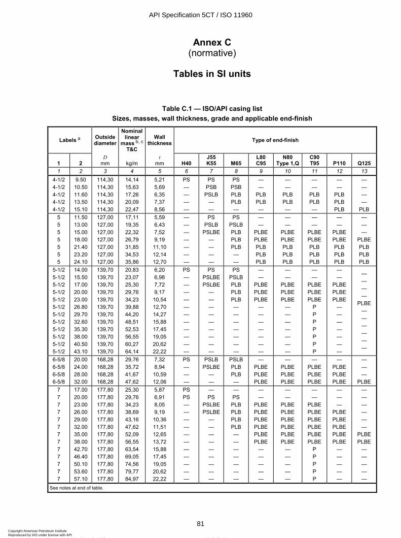
ISO 11960:2004(E)
© ISO 2004 – All rights reserved 81
Annex C (normative)
Tables in SI units
Table C.1 — ISO/API casing list Sizes, masses, wall thickness, grade and applicable end-finish
Labels a Outside diameter
Nominal linear
mass b, c T&C
Wall thickness Type of end-finish
1
2
D mm
kg/m
t mm
H40
J55 K55
M65
L80 C95
N80 Type 1,Q
C90 T95
P110
Q125
1 2 3 4 5 6 7 8 9 10 11 12 13 4-1/2 4-1/2 4-1/2 4-1/2 4-1/2
9.50 10.50 11.60 13.50 15.10
114,30 114,30 114,30 114,30 114,30
14,14 15,63 17,26 20,09 22,47
5,21 5,69 6,35 7,37 8,56
PS — — — —
PS PSB
PSLB — —
PS PSB PLB PLB —
— —
PLB PLB —
— —
PLB PLB —
— —
PLB PLB —
— —
PLB PLB PLB
— — — —
PLB 5 5 5 5 5 5 5
11.50 13.00 15.00 18.00 21.40 23.20 24.10
127,00 127,00 127,00 127,00 127,00 127,00 127,00
17,11 19,35 22,32 26,79 31,85 34,53 35,86
5,59 6,43 7,52 9,19 11,10 12,14 12,70
— — — — — — —
PS PSLB
PSLBE — — — —
PS PSLB PLB PLB PLB — —
— —
PLBE PLBE PLB PLB PLB
— —
PLBE PLBE PLB PLB PLB
— —
PLBE PLBE PLB PLB PLB
— —
PLBE PLBE PLB PLB PLB
— — —
PLBE PLB PLB PLB
5-1/2 5-1/2 5-1/2 5-1/2 5-1/2 5-1/2 5-1/2 5-1/2 5-1/2 5-1/2 5-1/2 5-1/2
14.00 15.50 17.00 20.00 23.00 26.80 29.70 32.60 35.30 38.00 40.50 43.10
139,70 139,70 139,70 139,70 139,70 139,70 139,70 139,70 139,70 139,70 139,70 139,70
20,83 23,07 25,30 29,76 34,23 39,88 44,20 48,51 52,53 56,55 60,27 64,14
6,20 6,98 7,72 9,17 10,54 12,70 14,27 15,88 17,45 19,05 20,62 22,22
PS — — — — — — — — — — —
PS PSLBE PSLBE
— — — — — — — — —
PS PSLB PLB PLB PLB — — — — — — —
— —
PLBE PLBE PLBE
— — — — — — —
— —
PLBE PLBE PLBE
— — — — — — —
— —
PLBE PLBE PLBE
P P P P P P P
— —
PLBE PLBE PLBE
— — — — — — —
— — — —
PLBE — — — — — —
6-5/8 6-5/8 6-5/8 6-5/8
20.00 24.00 28.00 32.00
168,28 168,28 168,28 168,28
29,76 35,72 41,67 47,62
7,32 8,94 10,59 12,06
PS — — —
PSLB PSLBE
— —
PSLB PLB PLB —
— PLBE PLBE PLBE
— PLBE PLBE PLBE
— PLBE PLBE PLBE
— PLBE PLBE PLBE
— — —
PLBE 7 7 7 7 7 7 7 7 7 7 7 7 7
17.00 20.00 23.00 26.00 29.00 32.00 35.00 38.00 42.70 46.40 50.10 53.60 57.10
177,80 177,80 177,80 177,80 177,80 177,80 177,80 177,80 177,80 177,80 177,80 177,80 177,80
25,30 29,76 34,23 38,69 43,16 47,62 52,09 56,55 63,54 69,05 74,56 79,77 84,97
5,87 6,91 8,05 9,19 10,36 11,51 12,65 13,72 15,88 17,45 19,05 20,62 22,22
PS PS — — — — — — — — — — —
— PS
PSLBE PSLBE
— — — — — — — — —
— PS
PLB PLB PLB PLB — — — — — — —
— —
PLBE PLBE PLBE PLBE PLBE PLBE
— — — — —
— —
PLBE PLBE PLBE PLBE PLBE PLBE
— — — — —
— —
PLBE PLBE PLBE PLBE PLBE PLBE
P P P P P
— — —
PLBE PLBE PLBE PLBE PLBE
— — — — —
— — — — — —
PLBE PLBE
— — — — —
See notes at end of table.
API Specification 5CT / ISO 11960
81Copyright American Petroleum Institute Reproduced by IHS under license with API
Not for ResaleNo reproduction or networking permitted without license from IHS
--`,,,```-`-`,,`,,`,`,,`---
ISO 11960:2004(E)
82 © ISO 2004 – All rights reserved
Table C.1 (continued)
Labels a Outside diameter
Nominal linear
mass b, c
T&C
Wall thickness Type of end-finish
1
2
D mm
kg/m
t mm
H40
J55 K55
M65
L80 C95
N80 Type 1,Q
C90 T95
P110
Q125
1 2 3 4 5 6 7 8 9 10 11 12 13 7-5/8 7-5/8 7-5/8 7-5/8 7-5/8 7-5/8 7-5/8 7-5/8 7-5/8 7-5/8
24.00 26.40 29.70 33.70 39.00 42.80 45.30 47.10 51.20 55.30
193,68 193,68 193,68 193,68 193,68 193,68 193,68 193,68 193,68 193,68
35,72 39,29 44,20 50,15 58,04 63,69 67,41 70,09 76,19 82,30
7,62 8,33 9,52 10,92 12,70 14,27 15,11 15,88 17,45 19,05
PS — — — — — — — — —
— PSLBE
— — — — — — — —
— PSLB PLB PLB — — — — — —
— PLBE PLBE PLBE PLBE PLB PLB PLB — —
— PLBE PLBE PLBE PLBE PLB PLB PLB — —
— PLBE PLBE PLBE PLBE PLB PLB PLB
P P
— —
PLBE PLBE PLBE PLB PLB PLB — —
— — — —
PLBE PLB PLB PLB — —
7-3/4 46.10 196,85 68,60 15,11 — — — P P P P P 8-5/8 8-5/8 8-5/8 8-5/8 8-5/8 8-5/8 8-5/8
24.00 28.00 32.00 36.00 40.00 44.00 49.00
219,08 219,08 219,08 219,08 219,08 219,08 219,08
35,72 41,67 47,62 53,57 59,53 65,48 72,92
6,71 7,72 8,94 10,16 11,43 12,70 14,15
— PS PS — — — —
PS —
PSLBE PSLBE
— — —
PS PS
PSLB PSLB PLB — —
— — —
PLBE PLBE PLBE PLBE
— — —
PLBE PLBE PLBE PLBE
— — —
PLBE PLBE PLBE PLBE
— — — —
PLBE PLBE PLBE
— — — — — —
PLBE 9-5/8 9-5/8 9-5/8 9-5/8 9-5/8 9-5/8 9-5/8 9-5/8 9-5/8 9-5/8 9-5/8
32.30 36.00 40.00 43.50 47.00 53.50 58.40 59.40 64.90 70.30 75.60
244,48 244,48 244,48 244,48 244,48 244,48 244,48 244,48 244,48 244,48 244,48
48,07 53,57 59,53 64,73 69,94 79,62 86,91 88,40 96,58
104,62 112,50
7,92 8,94 10,03 11,05 11,99 13,84 15,11 15,47 17,07 18,64 20,24
PS PS — — — — — — — — —
— PSLB
PSLBE — — — — — — — —
— PSLB PSLB PLB PLB — — — — — —
— —
PLBE PLBE PLBE PLBE PLB — — — —
— —
PLBE PLBE PLBE PLBE PLB — — — —
— —
PLBE PLBE PLBE PLBE PLB
P P P P
— — —
PLBE PLBE PLBE PLB — — — —
— — — —
PLBE PLBE PLB — — — —
10-3/4 10-3/4 10-3/4 10-3/4 10-3/4 10-3/4 10-3/4 10-3/4 10-3/4 10-3/4
32.75 40.50 45.50 51.00 55.50 60.70 65.70 73.20 79.20 85.30
273,05 273,05 273,05 273,05 273,05 273,05 273,05 273,05 273,05 273,05
48,74 60,27 67,71 75,90 82,59 90,33 97,77
108,93 117,86 126,94
7,09 8,89 10,16 11,43 12,57 13,84 15,11 17,07 18,64 20,24
PS PS — — — — — — — —
— PSB
PSBE PSBE
— — — — — —
— PSB PSB PSB PSB — — — — —
— — —
PSBE PSBE
— — — — —
— — —
PSBE PSBE
— — — — —
— — —
PSBE PSBE PSBE PSB
P P P
— — —
PSBE PSBE PSBE PSB — — —
— — — — —
PSBE PSB — — —
11-3/4 11-3/4 11-3/4 11-3/4 11-3/4 11-3/4
42.00 47.00 54.00 60.00 65.00 71.00
298,45 298,45 298,45 298,45 298,45 298,45
62,50 69,94 80,36 89,29 96,73
105,66
8,46 9,53 11,05 12,42 13,56 14,78
PS — — — — —
— PSB PSB PSB — —
— PSB PSB PSB — —
— — —
PSB P P
— — —
PSB P P
— — —
PSB P P
— — —
PSB P P
— — —
PSB P P
13-3/8 13-3/8 13-3/8 13-3/8 13-3/8
48.00 54.50 61.00 68.00 72.00
339,72 339,72 339,72 339,72 339,72
71,43 81,10 90,78
101,19 107,15
8,38 9,65 10,92 12,19 13,06
PS — — — —
— PSB PSB PSB —
— PSB PSB PSB —
— — —
PSB PSB
— — —
PSB PSB
— — —
PSB PSB
— — —
PSB PSB
— — — —
PSB See notes at end of table.
API Specification 5CT / ISO 11960
82Copyright American Petroleum Institute Reproduced by IHS under license with API
Not for ResaleNo reproduction or networking permitted without license from IHS
--`,,,```-`-`,,`,,`,`,,`---
ISO 11960:2004(E)
© ISO 2004 – All rights reserved 83
Table C.1 (continued)
Labels a Outside diameter
Nominal linear
mass b, c T&C
Wall thickness Type of end-finish
1
2
D mm
kg/m
t mm
H40
J55 K55
M65
L80 C95
N80 Type 1,Q
C90 T95
P110
Q125
1 2 3 4 5 6 7 8 9 10 11 12 13 16 16 16 16
65.00 75.00 84.00 109.00
406,40 406,40 406,40 406,40
96,73 111,61 125,01 162,21
9,53 11,13 12,57 16,66
PS — — —
— PSB PSB
P
— PSB PSB —
— — — P
— — — P
— — — —
— — — P
— — — P
18-5/8 87.50 473,08 130,21 11,05 PS PSB PSB — — — — — 20 20 20
94.00 106.50 133.00
508,00 508,00 508,00
139,89 158,49 197,93
11,13 12,70 16,13
PSL — —
PSLB PSLB PSLB
PSLB PSLB
—
— — —
— — —
— — —
— — —
— — —
P = Plain end, S = Short round thread, L = Long round thread, B = Buttress thread, E = Extreme-line. a Labels are for information and assistance in ordering. b Nominal linear masses, threaded and coupled (col. 2) are shown for information only. c The densities of martensitic chromium steels (L80 types 9Cr and 13Cr) are different from carbon steels. The masses shown are therefore not accurate for martensitic chromium steels. A mass correction factor of 0,989 may be used.
Table C.2 — ISO/API plain-end casing liner list — Grade J55
Labels Outside diameter D
Plain-end linear mass
Wall thickness t
1 2 mm kg/m mm 1 2 3 4 5
3-1/2 4
4-1/2 5
5-1/2 6-5/8
9.92 11.35 13.05 17.95 19.83 27.66
88,90 101,60 114,30 127,00 139,70 168,28
14,76 16,89 19,42 26,71 29,51 41,18
7,34 7,26 7,37 9,19 9,17 10,59
API Specification 5CT / ISO 11960
83Copyright American Petroleum Institute Reproduced by IHS under license with API
Not for ResaleNo reproduction or networking permitted without license from IHS
--`,,,```-`-`,,`,,`,`,,`---
ISO 11960:2004(E)
84 © ISO 2004 – All rights reserved
Table C.3 — ISO/API tubing list Sizes, masses, wall thickness, grade and applicable end-finish
Nominal linear masses a, b Labels
1 2
Outside diameter Non-
upset T&C
Ext. upset T&C
Integ. joint
Wall thick-ness
Type of end finish c
NU T&C
EU T&C
IJ D mm
kg/m
kg/m
kg/m
t mm
H40 J55 L80 N80 Type 1,Q
C90 T95 P110
1 2 3 4 5 6 7 8 9 10 11 12 13 14 15 16 1.050 1.050
1.14 1.48
1.20 1.54
— —
26,67 26,67
1,70 2,20
1,79 2,29
— —
2,87 3,91
PNU PU
PNU PU
PNU PU
PNU PU
PNU PU
PNU PU
— PU
1.315 1.315
1.70 2.19
1.80 2.24
1.72 —
33,40 33,40
2,53 3,26
2,68 3,33
2,56 —
3,38 4,55
PNUI PU
PNUI PU
PNUI PU
PNUI PU
PNUI PU
PNUI PU
— PU
1.660 1.660 1.660
2.09 2.30 3.03
— 2.40 3.07
2.10 2.33 —
42,16 42,16 42,16
— 3,42 4,51
— 3,57 4,57
3,13 3,47 —
3,18 3,56 4,85
PI PNUI PU
PI PNUI PU
— PNUI PU
— PNUI PU
— PNUI PU
— PNUI PU
— — PU
1.900 1.900 1.900 1.900 1.900
2.40 2.75 3.65 4.42 5.15
— 2.90 3.73 — —
2.40 2.76 — — —
48,26 48,26 48,26 48,26 48,26
— 4,09 5,43 6,58 7,66
— 4,32 5,55 — —
3,57 4,11 — — —
3,18 3,68 5,08 6,35 7,62
PI PNUI PU — —
PI PNUI PU — —
— PNUI PU P P
— PNUI PU — —
— PNUI PU P P
— PNUI PU P P
— — PU — —
2.063 2.063
3.24 4.50
— —
3.25 —
52,40 52,40
— —
— —
4,84 —
3,96 5,72
PI P
PI P
PI P
PI P
PI P
PI P
— P
2-3/8 2-3/8 2-3/8 2-3/8 2-3/8
4.00 4.60 5.80 6.60 7.35
— 4.70 5.95 —
7.45
— — — — —
60,32 60,32 60,32 60,32 60,32
5,95 6,85 8,63 9,82 10,94
— 6,99 8,85 —
11,09
— — — — —
4,24 4,83 6,45 7,49 8,53
PN PNU — — —
PN PNU — — —
PN PNU PNU
P PU
PN PNU PNU — —
PN PNU PNU
P PU
PN PNU PNU
P PU
— PNU PNU — —
2-7/8 2-7/8 2-7/8 2-7/8 2-7/8 2-7/8
6.40 7.80 8.60 9.35 10.50 11.50
6.50 7.90 8.70 9.45 — —
— — — — — —
73,02 73,02 73,02 73,02 73,02 73,02
9,52 11,61 12,80 13,91 15,63 17,11
9,67 11,76 12,95 14,06
— —
— — — — — —
5,51 7,01 7,82 8,64 9,96
11,18
PNU — — — — —
PNU — — — — —
PNU PNU PNU PU P P
PNU PNU PNU — — —
PNU PNU PNU PU P P
PNU PNU PNU PU P P
PNU PNU PNU — — —
3-1/2 3-1/2 3-1/2 3-1/2 3-1/2 3-1/2 3-1/2
7.70 9.20 10.20 12.70 14.30 15.50 17.00
— 9.30 —
12.95 — — —
— — — — — — —
88,90 88,90 88,90 88,90 88,90 88,90 88,90
11,46 13,69 15,18 18,90 21,28 23,07 25,30
— 13,84
— 19,27
— — —
— — — — — — —
5,49 6,45 7,34 9,52
10,92 12,09 13,46
PN PNU PN — — — —
PN PNU PN — — — —
PN PNU PN
PNU P P P
PN PNU PN
PNU — — —
PN PNU PN
PNU P P P
PN PNU PN
PNU P P P
— PNU —
PNU — — —
4 4 4 4 4 4
9.50 10.70 13.20 16.10 18.90 22.20
— 11.00
— — — —
— — — — — —
101,60 101,60 101,60 101,60 101,60 101,60
14,14 —
19,64 23,96 28,13 33,04
— 16,37
— — — —
— — — — — —
5,74 6,65 8,38
10,54 12,70 15,49
PN PU — — — —
PN PU — — — —
PN PU P P P P
PN PU — — — —
PN PU P P P P
PN PU P P P P
— — — — — —
4-1/2 4-1/2 4-1/2 4-1/2 4-1/2 4-1/2 4-1/2
12.60 15.20 17.00 18.90 21.50 23.70 26.10
12.75 — — — — — —
— — — — — — —
114,30 114,30 114,30 114,30 114,30 114,30 114,30
18,75 22,62 25,30 28,13 32,00 35,27 38,84
18,97 — — — — — —
— — — — — — —
6,88 8,56 9,65
10,92 12,70 14,22 16,00
PNU — — — — — —
PNU — — — — — —
PNU P P P P P P
PNU — — — — — —
PNU P P P P P P
PNU P P P P P P
— — — — — — —
P = Plain end, N = Non-upset threaded and coupled, U = External upset threaded and coupled, I = Integral joint. a Nominal linear masses, threads and coupling (col. 2, 3, 4) are shown for information only. b The densities of martensitic chromium steels (L80 types 9Cr and 13Cr) are different from carbon steels. The masses shown are therefore not accurate for martensitic chromium steels. A mass correction factor of 0,989 may be used. c Non-upset tubing is available with regular couplings or special bevel couplings. External-upset tubing is available with regular, special-bevel, or special clearance couplings.
API Specification 5CT / ISO 11960
84Copyright American Petroleum Institute Reproduced by IHS under license with API
Not for ResaleNo reproduction or networking permitted without license from IHS
--`,,,```-`-`,,`,,`,`,,`---
ISO 11960:2004(E)
© ISO 2004 – All rights reserved 85
Table C.4 — Process of manufacture and heat treatment
Group Grade Type Manufacturing process a Heat treatment Tempering temperature
°C min.
1 2 3 4 5 6 1 H40
J55 K55 N80 N80
— — — 1 Q
S or EW S or EW S or EW S or EW S or EW
None None b None b
c Q&T
— — — — —
2 M65 L80 L80 L80 C90 C90 C95 T95 T95
— 1
9Cr 13Cr
1 2 — 1 2
S or EW S or EW
S S S S
S or EW S S
d Q&T
Q&T e Q&T e Q&T Q&T Q&T Q&T Q&T
— 566 593 593 621 621 538 649 649
3 P110 — S or EW f, g Q&T — 4 Q125
Q125 Q125 Q125
1 2 3 4
S or EW g S or EW g S or EW g S or EW g
Q&T Q&T Q&T Q&T
— — — —
a S = seamless process; EW = electric-welded process. b Full length normalized (N), normalized and tempered (N&T), or quenched and tempered (Q&T), at the manufacturer's option or as specified on the purchase agreement. c Full length normalized or normalized and tempered at the manufacturer's option. d All pipe shall be full body heat-treated. Full length normalized (N), normalized and tempered (N&T), or quenched and tempered (Q&T), at the manufacturer's option or as specified on the purchase agreement. e Type 9Cr and 13Cr may be air-quenched. f Special chemical requirements for electric-welded P110 casing are specified in Table C.5. g Special requirements unique to electric-welded P110 and Q125 are specified in A.6 (SR11).
API Specification 5CT / ISO 11960
85Copyright American Petroleum Institute Reproduced by IHS under license with API
Not for ResaleNo reproduction or networking permitted without license from IHS
--`,,,```-`-`,,`,,`,`,,`---
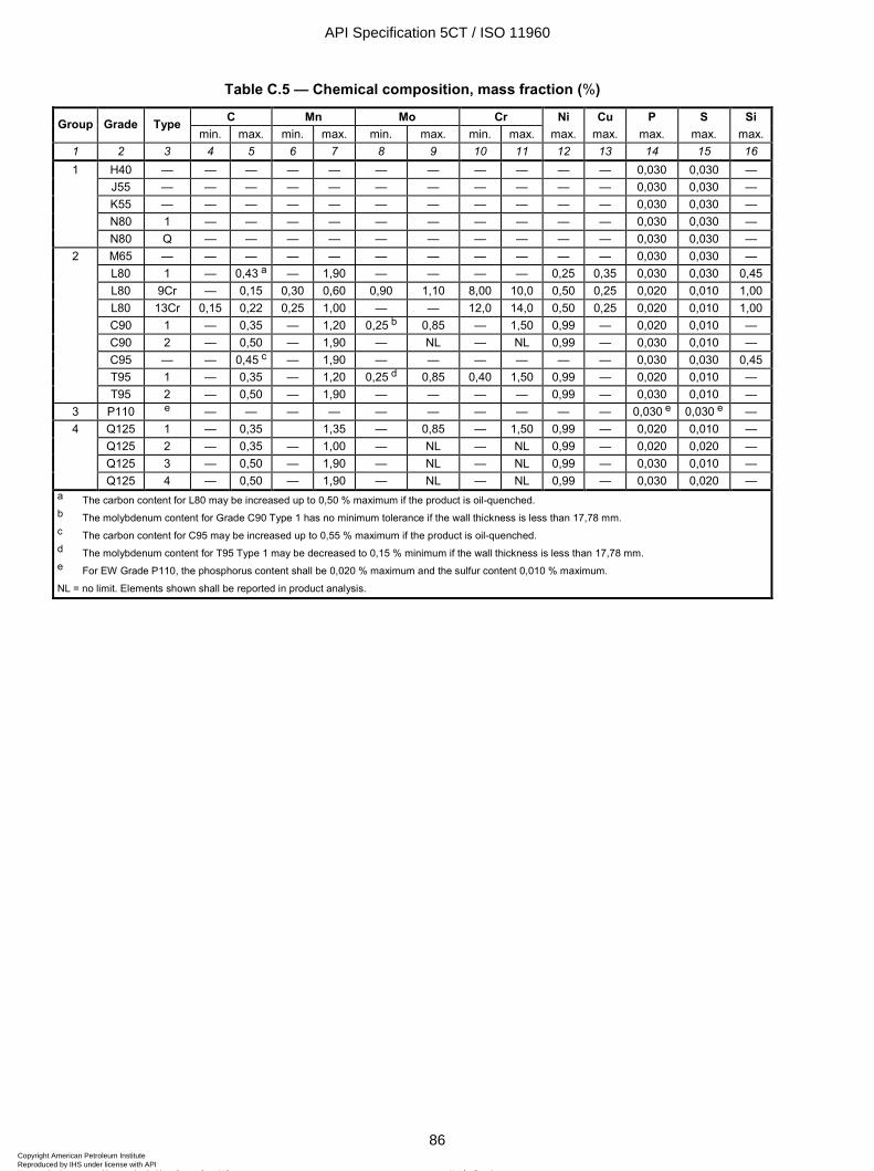
ISO 11960:2004(E)
86 © ISO 2004 – All rights reserved
Table C.5 — Chemical composition, mass fraction (%)
C Mn Mo Cr Ni Cu P S Si Group Grade Type min. max. min. max. min. max. min. max. max. max. max. max. max.
1 2 3 4 5 6 7 8 9 10 11 12 13 14 15 16 H40 — — — — — — — — — — — 0,030 0,030 — J55 — — — — — — — — — — — 0,030 0,030 — K55 — — — — — — — — — — — 0,030 0,030 — N80 1 — — — — — — — — — — 0,030 0,030 —
1
N80 Q — — — — — — — — — — 0,030 0,030 — M65 — — — — — — — — — — — 0,030 0,030 — L80 1 — 0,43 a — 1,90 — — — — 0,25 0,35 0,030 0,030 0,45 L80 9Cr — 0,15 0,30 0,60 0,90 1,10 8,00 10,0 0,50 0,25 0,020 0,010 1,00 L80 13Cr 0,15 0,22 0,25 1,00 — — 12,0 14,0 0,50 0,25 0,020 0,010 1,00 C90 1 — 0,35 — 1,20 0,25 b 0,85 — 1,50 0,99 — 0,020 0,010 — C90 2 — 0,50 — 1,90 — NL — NL 0,99 — 0,030 0,010 — C95 — — 0,45 c — 1,90 — — — — — — 0,030 0,030 0,45 T95 1 — 0,35 — 1,20 0,25 d 0,85 0,40 1,50 0,99 — 0,020 0,010 —
2
T95 2 — 0,50 — 1,90 — — — — 0,99 — 0,030 0,010 — 3 P110 e — — — — — — — — — — 0,030 e 0,030 e —
Q125 1 — 0,35 1,35 — 0,85 — 1,50 0,99 — 0,020 0,010 — Q125 2 — 0,35 — 1,00 — NL — NL 0,99 — 0,020 0,020 — Q125 3 — 0,50 — 1,90 — NL — NL 0,99 — 0,030 0,010 —
4
Q125 4 — 0,50 — 1,90 — NL — NL 0,99 — 0,030 0,020 — a The carbon content for L80 may be increased up to 0,50 % maximum if the product is oil-quenched. b The molybdenum content for Grade C90 Type 1 has no minimum tolerance if the wall thickness is less than 17,78 mm. c The carbon content for C95 may be increased up to 0,55 % maximum if the product is oil-quenched. d The molybdenum content for T95 Type 1 may be decreased to 0,15 % minimum if the wall thickness is less than 17,78 mm. e For EW Grade P110, the phosphorus content shall be 0,020 % maximum and the sulfur content 0,010 % maximum.
NL = no limit. Elements shown shall be reported in product analysis.
API Specification 5CT / ISO 11960
86Copyright American Petroleum Institute Reproduced by IHS under license with API
Not for ResaleNo reproduction or networking permitted without license from IHS
--`,,,```-`-`,,`,,`,`,,`---
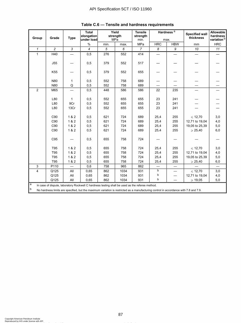
ISO 11960:2004(E)
© ISO 2004 – All rights reserved 87
Table C.6 — Tensile and hardness requirements
Total elongation under load
Yield strength
MPa
Tensile strength
min.
Hardness a
max. Specified wall
thickness Allowable hardness variation bGroup Grade Type
% min. max. MPa HRC HBW mm HRC 1 2 3 4 5 6 7 8 9 10 11 1 H40
J55
K55
N80 N80
—
—
— 1 Q
0,5
0,5
0,5
0,5 0,5
276
379
379
552 552
552
552
552
758 758
414
517
655
689 689
—
—
—
— —
—
—
—
— —
—
—
—
— —
—
—
—
— —
2 M65
L80 L80 L80
C90 C90 C90 C90
C95
T95 T95 T95 T95
— 1
9Cr 13Cr
1 & 2 1 & 2 1 & 2 1 & 2
—
1 & 2 1 & 2 1 & 2 1 & 2
0,5
0,5 0,5 0,5
0,5 0,5 0,5 0,5
0,5
0,5 0,5 0,5 0,5
448
552 552 552
621 621 621 621
655
655 655 655 655
586
655 655 655
724 724 724 724
758
758 758 758 758
586
655 655 655
689 689 689 689
724
724 724 724 724
22
23 23 23
25,4 25,4 25,4 25,4
—
25,4 25,4 25,4 25,4
235
241 241 241
255 255 255 255
—
255 255 255 255
—
— — —
u 12,70 12,71 to 19,04 19,05 to 25,39
W 25,40
—
u 12,70 12,71 to 19,04 19,05 to 25,39
W 25,40
—
— — —
3,0 4,0 5,0 6,0
—
3,0 4,0 5,0 6,0
3 P110 — 0,6 758 965 862 — — — — 4 Q125
Q125 Q125
All All All
0,65 0,65 0,65
862 862 862
1034 1034 1034
931 931 931
b b b
— — —
u 12,70 12,71 to 19,04
W 19,05
3,0 4,0 5,0
a In case of dispute, laboratory Rockwell C hardness testing shall be used as the referee method. b No hardness limits are specified, but the maximum variation is restricted as a manufacturing control in accordance with 7.8 and 7.9.
API Specification 5CT / ISO 11960
87Copyright American Petroleum Institute Reproduced by IHS under license with API
Not for ResaleNo reproduction or networking permitted without license from IHS
--`,,,```-`-`,,`,,`,`,,`---
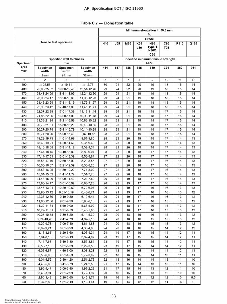
ISO 11960:2004(E)
88 © ISO 2004 – All rights reserved
Table C.7 — Elongation table
Minimum elongation in 50,8 mm %
Grade Tensile test specimen H40 J55 M65 K55
L80 N80
Type 1 N80Q C90
C95 T95
P110 Q125
Specified wall thickness mm
Specified minimum tensile strength MPa Specimen
area mm2
Specimen width 19 mm
Specimen width 25 mm
Specimen width 38 mm
414 517 586 655 689 724 862 931
1 2 3 4 5 6 7 8 9 10 11 12 490 W 25,53 W 19,41 W 12,77 30 24 22 20 19 18 15 14 480 25,00-25,52 19,00-19,40 12,51-12,76 29 24 22 20 19 18 15 14 470 24,48-24,99 18,61-18,99 12,24-12,50 29 24 21 19 19 18 15 14 460 23,95-24,47 18,20-18,60 11,98-12,23 29 24 21 19 18 18 15 14 450 23,43-23,94 17,81-18,19 11,72-11,97 29 24 21 19 18 18 15 14 440 22,90-23,42 17,40-17,80 11,45-11,71 29 24 21 19 18 18 15 14 430 22,37-22,89 17,01-17,39 11,19-11,44 29 24 21 19 18 17 15 14 420 21,85-22,36 16,60-17,00 10,93-11,18 29 24 21 19 18 17 15 14 410 21,32-21,84 16,21-16,59 10,66-10,92 29 23 21 19 18 17 15 14 400 20,79-21,31 15,80-16,20 10,40-10,65 28 23 21 19 18 17 15 14 390 20,27-20,78 15,41-15,79 10,14-10,39 28 23 21 19 18 17 15 14 380 19,74-20,26 15,00-15,40 9,87-10,13 28 23 21 19 18 17 15 14 370 19,22-19,73 14,61-14,99 9,61-9,86 28 23 20 19 18 17 14 13 360 18,69-19,21 14,20-14,60 9,35-9,60 28 23 20 18 18 17 14 13 350 18,16-18,68 13,81-14,19 9,08-9,34 28 23 20 18 18 17 14 13 340 17,64-18,15 13,40-13,80 8,82-9,07 28 23 20 18 17 17 14 13 330 17,11-17,63 13,01-13,39 8,56-8,81 27 22 20 18 17 17 14 13 320 16,58-17,10 12,60-13,00 8,29-8,55 27 22 20 18 17 16 14 13 310 16,06-16,57 12,21-12,59 8,03-8,28 27 22 20 18 17 16 14 13 300 15,53-16,05 11,80-12,20 7,77-8,02 27 22 20 18 17 16 14 13 290 15,01-15,52 11,41-11,79 7,51-7,76 27 22 20 18 17 16 14 13 280 14,48-15,00 11,00-11,40 7,24-7,50 26 22 19 18 17 16 14 13 270 13,95-14,47 10,61-10,99 6,98-7,23 26 22 19 17 17 16 14 13 260 13,43-13,94 10,20-10,60 6,72-6,97 26 21 19 17 16 16 13 13 250 12,90-13,42 9,81-10,19 6,45-6,71 26 21 19 17 16 16 13 12 240 12,37-12,89 9,40-9,80 6,19-6,44 26 21 19 17 16 16 13 12 230 11,85-12,36 9,01-9,39 5,93-6,18 25 21 19 17 16 15 13 12 220 11,32-11,84 8,60-9,00 5,66-5,92 25 21 18 17 16 15 13 12 210 10,79-11,31 8,21-8,59 5,40-5,65 25 20 18 17 16 15 13 12 200 10,27-10,78 7,80-8,20 5,14-5,39 25 20 18 16 16 15 13 12 190 9,74-10,26 7,41-7,79 4,87-5,13 24 20 18 16 15 15 13 12 180 9,22-9,73 7,00-7,40 4,61-4,86 24 20 18 16 15 15 13 12 170 8,69-9,21 6,61-6,99 4,35-4,60 24 20 18 16 15 14 12 12 160 8,16-8,68 6,20-6,60 4,08-4,34 24 19 17 16 15 14 12 11 150 7,64-8,15 5,81-6,19 3,82-4,07 23 19 17 15 15 14 12 11 140 7,11-7,63 5,40-5,80 3,56-3,81 23 19 17 15 15 14 12 11 130 6,58-7,10 5,01-5,39 3,29-3,55 23 19 17 15 14 14 12 11 120 6,06-6,57 4,60-5,00 3,03-3,28 22 18 16 15 14 14 12 11 110 5,53-6,05 4,21-4,59 2,77-3,02 22 18 16 15 14 13 11 11 100 5,01-5,52 3,80-4,20 2,51-2,76 22 18 16 14 14 13 11 10 90 4,48-5,00 3,41-3,79 2,24-2,50 21 17 15 14 13 13 11 10 80 3,95-4,47 3,00-3,40 1,98-2,23 21 17 15 14 13 12 11 10 70 3,43-3,94 2,61-2,99 1,72-1,97 20 16 15 13 13 12 10 10 60 2,90-3,42 2,20-2,60 1,45-1,71 19 16 14 13 12 12 10 9,5 50 2,37-2,89 1,81-2,19 1,19-1,44 19 15 14 12 12 11 9,5 9
API Specification 5CT / ISO 11960
88Copyright American Petroleum Institute Reproduced by IHS under license with API
Not for ResaleNo reproduction or networking permitted without license from IHS
--`,,,```-`-`,,`,,`,`,,`---
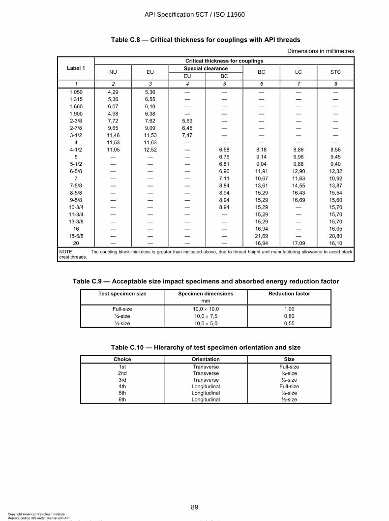
ISO 11960:2004(E)
© ISO 2004 – All rights reserved 89
Table C.8 — Critical thickness for couplings with API threads Dimensions in millimetres
Critical thickness for couplings Special clearance Label 1
NU EU EU BC
BC LC STC
1 2 3 4 5 6 7 8 1.050 1.315 1.660 1.900 2-3/8 2-7/8 3-1/2
4 4-1/2
5 5-1/2 6-5/8
7 7-5/8 8-5/8 9-5/8 10-3/4 11-3/4 13-3/8
16 18-5/8
20
4,29 5,36 6,07 4,98 7,72 9,65 11,46 11,53 11,05
— — — — — — — — — — — — —
5,36 6,55 6,10 6,38 7,62 9,09 11,53 11,63 12,52
— — — — — — — — — — — — —
— — — —
5,69 6,45 7,47 — — — — — — — — — — — — — — —
— — — — — — — —
6,58 6,76 6,81 6,96 7,11 8,84 8,94 8,94 8,94 — — — — —
— — — — — — — —
8,18 9,14 9,04 11,91 10,67 13,61 15,29 15,29 15,29 15,29 15,29 16,94 21,69 16,94
— — — — — — — —
8,86 9,96 9,88 12,90 11,63 14,55 16,43 16,69
— — — — —
17,09
— — — — — — — —
8,56 9,45 9,40 12,32 10,92 13,87 15,54 15,60 15,70 15,70 15,70 16,05 20,80 16,10
NOTE The coupling blank thickness is greater than indicated above, due to thread height and manufacturing allowance to avoid black crest threads.
Table C.9 — Acceptable size impact specimens and absorbed energy reduction factor
Test specimen size Specimen dimensions mm
Reduction factor
Full-size ¾-size ½-size
10,0 × 10,0 10,0 × 7,5 10,0 × 5,0
1,00 0,80 0,55
Table C.10 — Hierarchy of test specimen orientation and size Choice Orientation Size
1st 2nd 3rd 4th 5th 6th
Transverse Transverse Transverse Longitudinal Longitudinal Longitudinal
Full-size ¾-size ½-size
Full-size ¾-size ½-size
API Specification 5CT / ISO 11960
89Copyright American Petroleum Institute Reproduced by IHS under license with API
Not for ResaleNo reproduction or networking permitted without license from IHS
--`,,,```-`-`,,`,,`,`,,`---
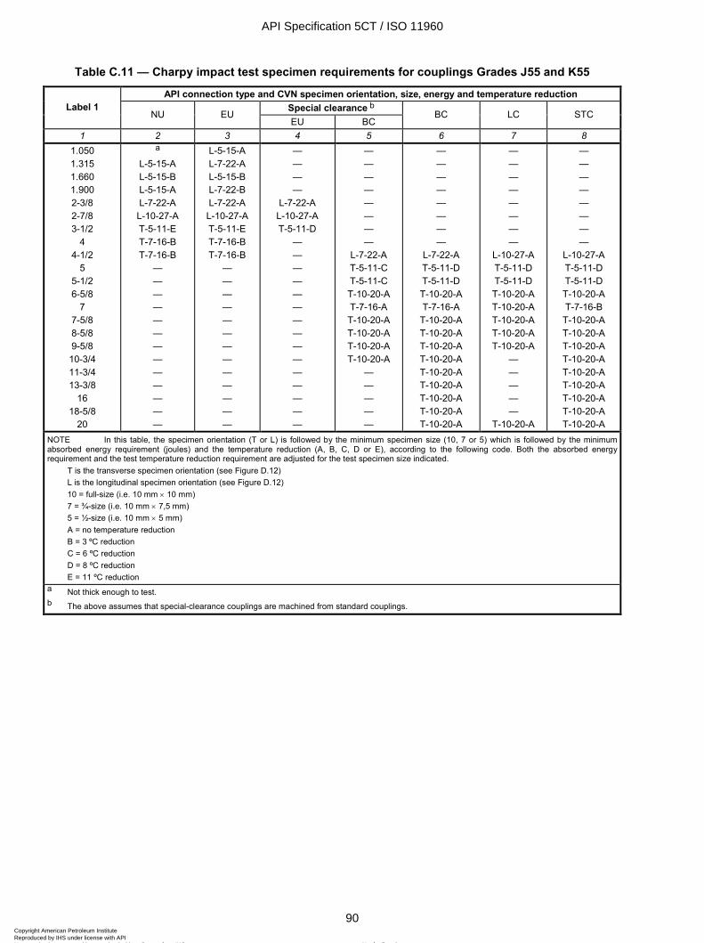
ISO 11960:2004(E)
90 © ISO 2004 – All rights reserved
Table C.11 — Charpy impact test specimen requirements for couplings Grades J55 and K55
API connection type and CVN specimen orientation, size, energy and temperature reduction Special clearance b Label 1
NU EU EU BC
BC LC STC
1 2 3 4 5 6 7 8 1.050 1.315 1.660 1.900 2-3/8 2-7/8 3-1/2
4 4-1/2
5 5-1/2 6-5/8
7 7-5/8 8-5/8 9-5/8 10-3/4 11-3/4 13-3/8
16 18-5/8
20
a
L-5-15-A L-5-15-B L-5-15-A L-7-22-A L-10-27-A T-5-11-E T-7-16-B T-7-16-B
— — — — — — — — — — — — —
L-5-15-A L-7-22-A L-5-15-B L-7-22-B L-7-22-A L-10-27-A T-5-11-E T-7-16-B T-7-16-B
— — — — — — — — — — — — —
— — — —
L-7-22-A L-10-27-A T-5-11-D
— — — — — — — — — — — — — — —
— — — — — — — —
L-7-22-A T-5-11-C T-5-11-C T-10-20-A T-7-16-A T-10-20-A T-10-20-A T-10-20-A T-10-20-A
— — — — —
— — — — — — — —
L-7-22-A T-5-11-D T-5-11-D T-10-20-A T-7-16-A
T-10-20-A T-10-20-A T-10-20-A T-10-20-A T-10-20-A T-10-20-A T-10-20-A T-10-20-A T-10-20-A
— — — — — — — —
L-10-27-A T-5-11-D T-5-11-D T-10-20-A T-10-20-A T-10-20-A T-10-20-A T-10-20-A
— — — — —
T-10-20-A
— — — — — — — —
L-10-27-A T-5-11-D T-5-11-D T-10-20-A T-7-16-B
T-10-20-A T-10-20-A T-10-20-A T-10-20-A T-10-20-A T-10-20-A T-10-20-A T-10-20-A T-10-20-A
NOTE In this table, the specimen orientation (T or L) is followed by the minimum specimen size (10, 7 or 5) which is followed by the minimum absorbed energy requirement (joules) and the temperature reduction (A, B, C, D or E), according to the following code. Both the absorbed energy requirement and the test temperature reduction requirement are adjusted for the test specimen size indicated.
T is the transverse specimen orientation (see Figure D.12) L is the longitudinal specimen orientation (see Figure D.12) 10 = full-size (i.e. 10 mm × 10 mm) 7 = ¾-size (i.e. 10 mm × 7,5 mm) 5 = ½-size (i.e. 10 mm × 5 mm) A = no temperature reduction B = 3 ºC reduction C = 6 ºC reduction D = 8 ºC reduction E = 11 ºC reduction
a Not thick enough to test. b The above assumes that special-clearance couplings are machined from standard couplings.
API Specification 5CT / ISO 11960
90Copyright American Petroleum Institute Reproduced by IHS under license with API
Not for ResaleNo reproduction or networking permitted without license from IHS
--`,,,```-`-`,,`,,`,`,,`---
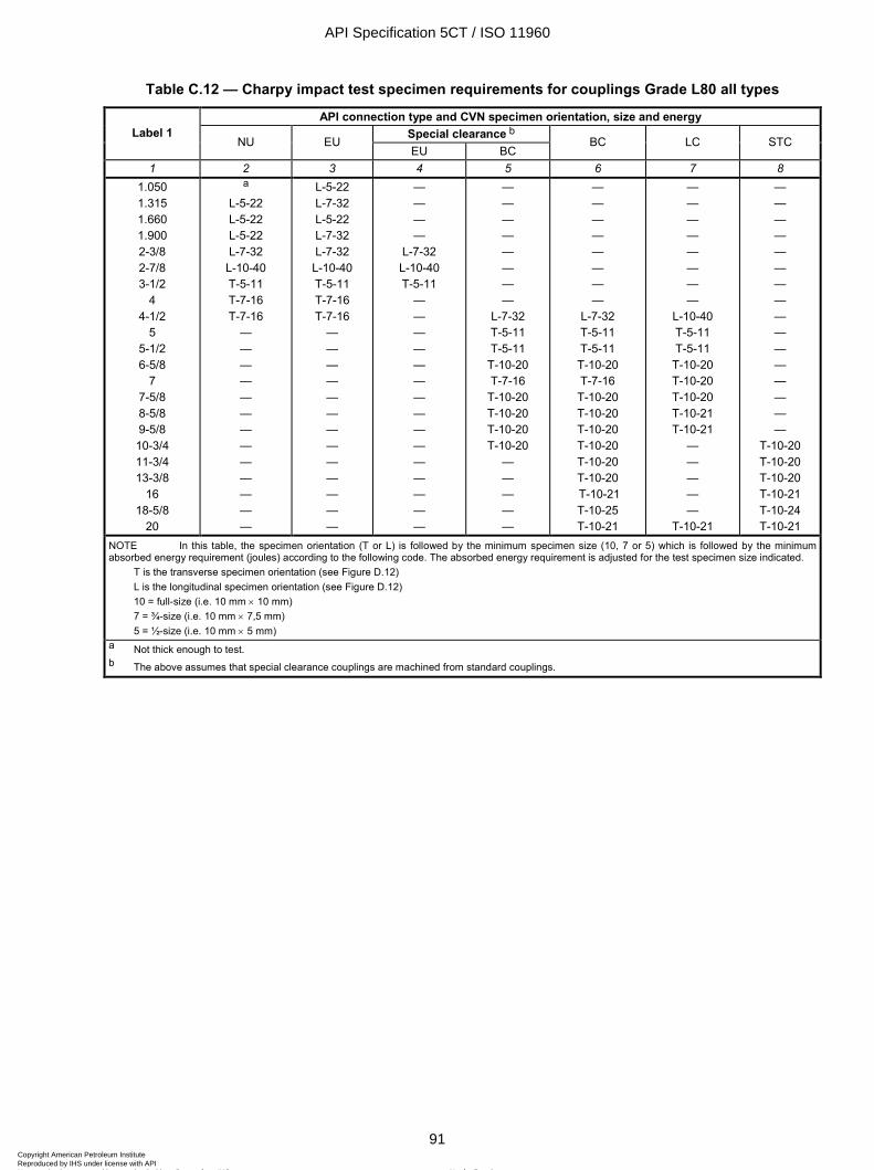
ISO 11960:2004(E)
© ISO 2004 – All rights reserved 91
Table C.12 — Charpy impact test specimen requirements for couplings Grade L80 all types
API connection type and CVN specimen orientation, size and energy Special clearance b Label 1
NU EU EU BC
BC LC STC
1 2 3 4 5 6 7 8 1.050 1.315 1.660 1.900 2-3/8 2-7/8 3-1/2
4 4-1/2
5 5-1/2 6-5/8
7 7-5/8 8-5/8 9-5/8 10-3/4 11-3/4 13-3/8
16 18-5/8
20
a
L-5-22 L-5-22 L-5-22 L-7-32
L-10-40 T-5-11 T-7-16 T-7-16
— — — — — — — — — — — — —
L-5-22 L-7-32 L-5-22 L-7-32 L-7-32
L-10-40 T-5-11 T-7-16 T-7-16
— — — — — — — — — — — — —
— — — —
L-7-32 L-10-40 T-5-11
— — — — — — — — — — — — — — —
— — — — — — — —
L-7-32 T-5-11 T-5-11
T-10-20 T-7-16
T-10-20 T-10-20 T-10-20 T-10-20
— — — — —
— — — — — — — —
L-7-32 T-5-11 T-5-11 T-10-20 T-7-16 T-10-20 T-10-20 T-10-20 T-10-20 T-10-20 T-10-20 T-10-21 T-10-25 T-10-21
— — — — — — — —
L-10-40 T-5-11 T-5-11
T-10-20 T-10-20 T-10-20 T-10-21 T-10-21
— — — — —
T-10-21
— — — — — — — — — — — — — — — —
T-10-20 T-10-20 T-10-20 T-10-21 T-10-24 T-10-21
NOTE In this table, the specimen orientation (T or L) is followed by the minimum specimen size (10, 7 or 5) which is followed by the minimum absorbed energy requirement (joules) according to the following code. The absorbed energy requirement is adjusted for the test specimen size indicated.
T is the transverse specimen orientation (see Figure D.12) L is the longitudinal specimen orientation (see Figure D.12) 10 = full-size (i.e. 10 mm × 10 mm) 7 = ¾-size (i.e. 10 mm × 7,5 mm) 5 = ½-size (i.e. 10 mm × 5 mm)
a Not thick enough to test. b The above assumes that special clearance couplings are machined from standard couplings.
API Specification 5CT / ISO 11960
91Copyright American Petroleum Institute Reproduced by IHS under license with API
Not for ResaleNo reproduction or networking permitted without license from IHS
--`,,,```-`-`,,`,,`,`,,`---
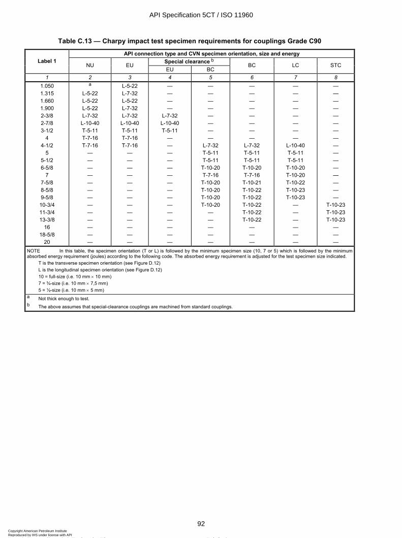
ISO 11960:2004(E)
92 © ISO 2004 – All rights reserved
Table C.13 — Charpy impact test specimen requirements for couplings Grade C90
API connection type and CVN specimen orientation, size and energy Special clearance b Label 1
NU EU EU BC
BC LC STC
1 2 3 4 5 6 7 8 1.050 1.315 1.660 1.900 2-3/8 2-7/8 3-1/2
4 4-1/2
5 5-1/2 6-5/8
7 7-5/8 8-5/8 9-5/8 10-3/4 11-3/4 13-3/8
16 18-5/8
20
a
L-5-22 L-5-22 L-5-22 L-7-32
L-10-40 T-5-11 T-7-16 T-7-16
— — — — — — — — — — — — —
L-5-22 L-7-32 L-5-22 L-7-32 L-7-32
L-10-40 T-5-11 T-7-16 T-7-16
— — — — — — — — — — — — —
— — — —
L-7-32 L-10-40 T-5-11
— — — — — — — — — — — — — — —
— — — — — — — —
L-7-32 T-5-11 T-5-11
T-10-20 T-7-16
T-10-20 T-10-20 T-10-20 T-10-20
— — — — —
— — — — — — — —
L-7-32 T-5-11 T-5-11 T-10-20 T-7-16 T-10-21 T-10-22 T-10-22 T-10-22 T-10-22 T-10-22
— — —
— — — — — — — —
L-10-40 T-5-11 T-5-11
T-10-20 T-10-20 T-10-22 T-10-23 T-10-23
— — — — — —
— — — — — — — — — — — — — — — —
T-10-23 T-10-23 T-10-23
— — —
NOTE In this table, the specimen orientation (T or L) is followed by the minimum specimen size (10, 7 or 5) which is followed by the minimum absorbed energy requirement (joules) according to the following code. The absorbed energy requirement is adjusted for the test specimen size indicated.
T is the transverse specimen orientation (see Figure D.12) L is the longitudinal specimen orientation (see Figure D.12) 10 = full-size (i.e. 10 mm × 10 mm) 7 = ¾-size (i.e. 10 mm × 7,5 mm) 5 = ½-size (i.e. 10 mm × 5 mm)
a Not thick enough to test. b The above assumes that special-clearance couplings are machined from standard couplings.
API Specification 5CT / ISO 11960
92Copyright American Petroleum Institute Reproduced by IHS under license with API
Not for ResaleNo reproduction or networking permitted without license from IHS
--`,,,```-`-`,,`,,`,`,,`---
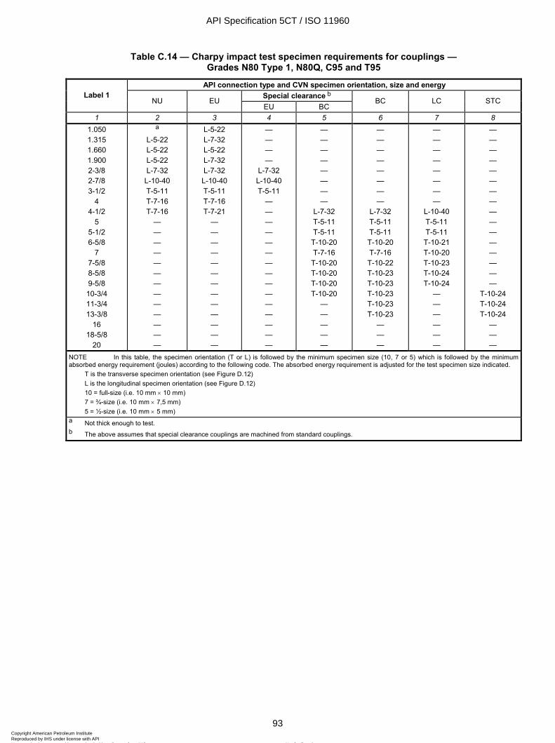
ISO 11960:2004(E)
© ISO 2004 – All rights reserved 93
Table C.14 — Charpy impact test specimen requirements for couplings — Grades N80 Type 1, N80Q, C95 and T95
API connection type and CVN specimen orientation, size and energy Special clearance b Label 1
NU EU EU BC
BC LC STC
1 2 3 4 5 6 7 8 1.050 1.315 1.660 1.900 2-3/8 2-7/8 3-1/2
4 4-1/2
5 5-1/2 6-5/8
7 7-5/8 8-5/8 9-5/8 10-3/4 11-3/4 13-3/8
16 18-5/8
20
a
L-5-22 L-5-22 L-5-22 L-7-32
L-10-40 T-5-11 T-7-16 T-7-16
— — — — — — — — — — — — —
L-5-22 L-7-32 L-5-22 L-7-32 L-7-32 L-10-40 T-5-11 T-7-16 T-7-21
— — — — — — — — — — — — —
— — — —
L-7-32 L-10-40 T-5-11
— — — — — — — — — — — — — — —
— — — — — — — —
L-7-32 T-5-11 T-5-11
T-10-20 T-7-16
T-10-20 T-10-20 T-10-20 T-10-20
— — — — —
— — — — — — — —
L-7-32 T-5-11 T-5-11 T-10-20 T-7-16 T-10-22 T-10-23 T-10-23 T-10-23 T-10-23 T-10-23
— — —
— — — — — — — —
L-10-40 T-5-11 T-5-11 T-10-21 T-10-20 T-10-23 T-10-24 T-10-24
— — — — — —
— — — — — — — — — — — — — — — —
T-10-24 T-10-24 T-10-24
— — —
NOTE In this table, the specimen orientation (T or L) is followed by the minimum specimen size (10, 7 or 5) which is followed by the minimum absorbed energy requirement (joules) according to the following code. The absorbed energy requirement is adjusted for the test specimen size indicated.
T is the transverse specimen orientation (see Figure D.12) L is the longitudinal specimen orientation (see Figure D.12) 10 = full-size (i.e. 10 mm × 10 mm) 7 = ¾-size (i.e. 10 mm × 7,5 mm) 5 = ½-size (i.e. 10 mm × 5 mm)
a Not thick enough to test. b The above assumes that special clearance couplings are machined from standard couplings.
API Specification 5CT / ISO 11960
93Copyright American Petroleum Institute Reproduced by IHS under license with API
Not for ResaleNo reproduction or networking permitted without license from IHS
--`,,,```-`-`,,`,,`,`,,`---
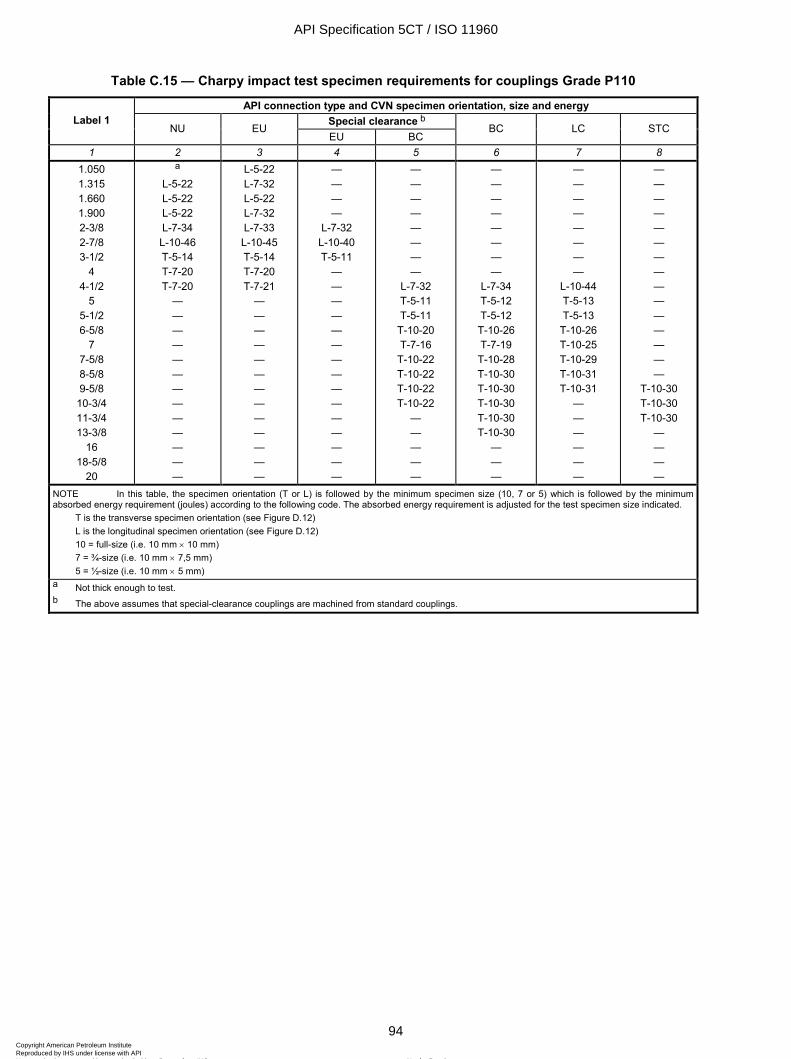
ISO 11960:2004(E)
94 © ISO 2004 – All rights reserved
Table C.15 — Charpy impact test specimen requirements for couplings Grade P110
API connection type and CVN specimen orientation, size and energy Special clearance b Label 1
NU EU EU BC
BC LC STC
1 2 3 4 5 6 7 8 1.050 1.315 1.660 1.900 2-3/8 2-7/8 3-1/2
4 4-1/2
5 5-1/2 6-5/8
7 7-5/8 8-5/8 9-5/8
10-3/4 11-3/4 13-3/8
16 18-5/8
20
a
L-5-22 L-5-22 L-5-22 L-7-34 L-10-46 T-5-14 T-7-20 T-7-20
— — — — — — — — — — — — —
L-5-22 L-7-32 L-5-22 L-7-32 L-7-33 L-10-45 T-5-14 T-7-20 T-7-21
— — — — — — — — — — — — —
— — — —
L-7-32 L-10-40 T-5-11
— — — — — — — — — — — — — — —
— — — — — — — —
L-7-32 T-5-11 T-5-11
T-10-20 T-7-16
T-10-22 T-10-22 T-10-22 T-10-22
— — — — —
— — — — — — — —
L-7-34 T-5-12 T-5-12 T-10-26 T-7-19 T-10-28 T-10-30 T-10-30 T-10-30 T-10-30 T-10-30
— — —
— — — — — — — —
L-10-44 T-5-13 T-5-13
T-10-26 T-10-25 T-10-29 T-10-31 T-10-31
— — — — — —
— — — — — — — — — — — — — — —
T-10-30 T-10-30 T-10-30
— — — —
NOTE In this table, the specimen orientation (T or L) is followed by the minimum specimen size (10, 7 or 5) which is followed by the minimum absorbed energy requirement (joules) according to the following code. The absorbed energy requirement is adjusted for the test specimen size indicated.
T is the transverse specimen orientation (see Figure D.12) L is the longitudinal specimen orientation (see Figure D.12) 10 = full-size (i.e. 10 mm × 10 mm) 7 = ¾-size (i.e. 10 mm × 7,5 mm) 5 = ½-size (i.e. 10 mm × 5 mm)
a Not thick enough to test. b The above assumes that special-clearance couplings are machined from standard couplings.
API Specification 5CT / ISO 11960
94Copyright American Petroleum Institute Reproduced by IHS under license with API
Not for ResaleNo reproduction or networking permitted without license from IHS
--`,,,```-`-`,,`,,`,`,,`---
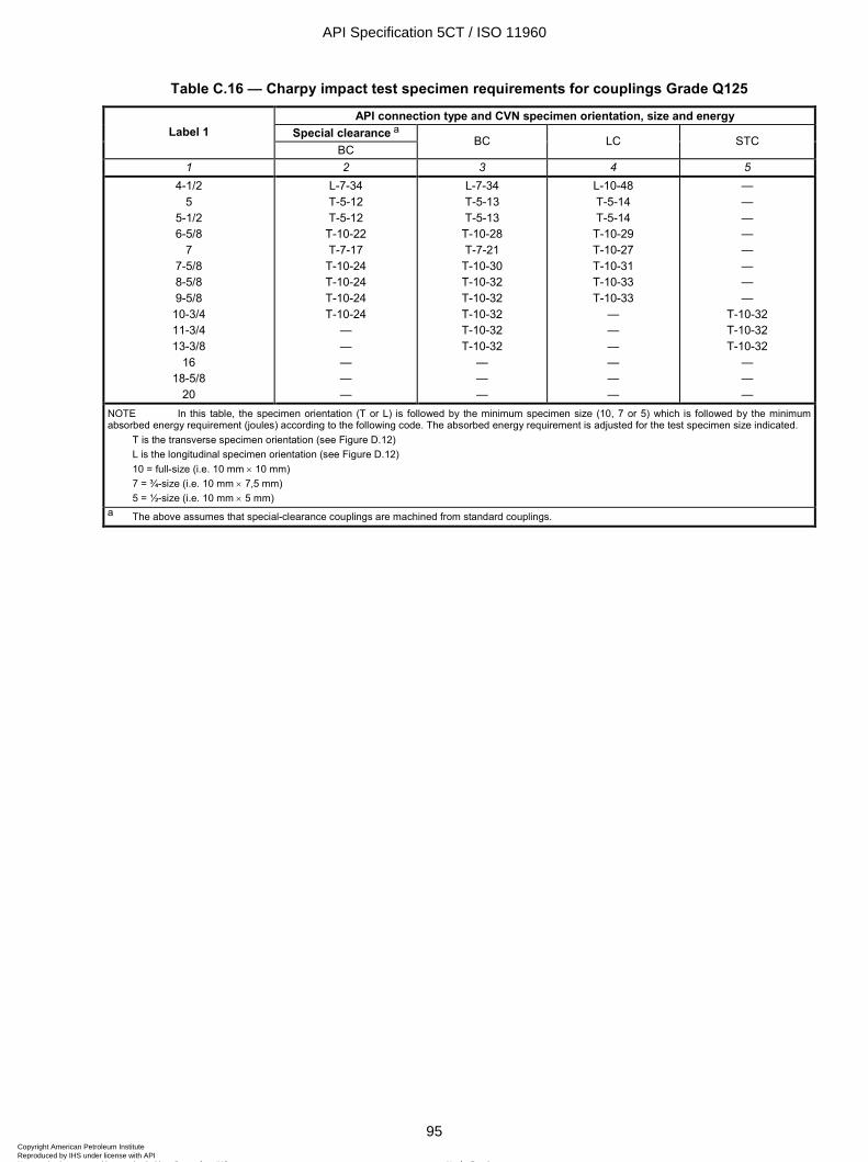
ISO 11960:2004(E)
© ISO 2004 – All rights reserved 95
Table C.16 — Charpy impact test specimen requirements for couplings Grade Q125
API connection type and CVN specimen orientation, size and energy Special clearance a Label 1
BC BC LC STC
1 2 3 4 5 4-1/2
5 5-1/2 6-5/8
7 7-5/8 8-5/8 9-5/8 10-3/4 11-3/4 13-3/8
16 18-5/8
20
L-7-34 T-5-12 T-5-12
T-10-22 T-7-17
T-10-24 T-10-24 T-10-24 T-10-24
— — — — —
L-7-34 T-5-13 T-5-13
T-10-28 T-7-21
T-10-30 T-10-32 T-10-32 T-10-32 T-10-32 T-10-32
— — —
L-10-48 T-5-14 T-5-14
T-10-29 T-10-27 T-10-31 T-10-33 T-10-33
— — — — — —
— — — — — — — —
T-10-32 T-10-32 T-10-32
— — —
NOTE In this table, the specimen orientation (T or L) is followed by the minimum specimen size (10, 7 or 5) which is followed by the minimum absorbed energy requirement (joules) according to the following code. The absorbed energy requirement is adjusted for the test specimen size indicated.
T is the transverse specimen orientation (see Figure D.12) L is the longitudinal specimen orientation (see Figure D.12) 10 = full-size (i.e. 10 mm × 10 mm) 7 = ¾-size (i.e. 10 mm × 7,5 mm) 5 = ½-size (i.e. 10 mm × 5 mm)
a The above assumes that special-clearance couplings are machined from standard couplings.
API Specification 5CT / ISO 11960
95Copyright American Petroleum Institute Reproduced by IHS under license with API
Not for ResaleNo reproduction or networking permitted without license from IHS
--`,,,```-`-`,,`,,`,`,,`---
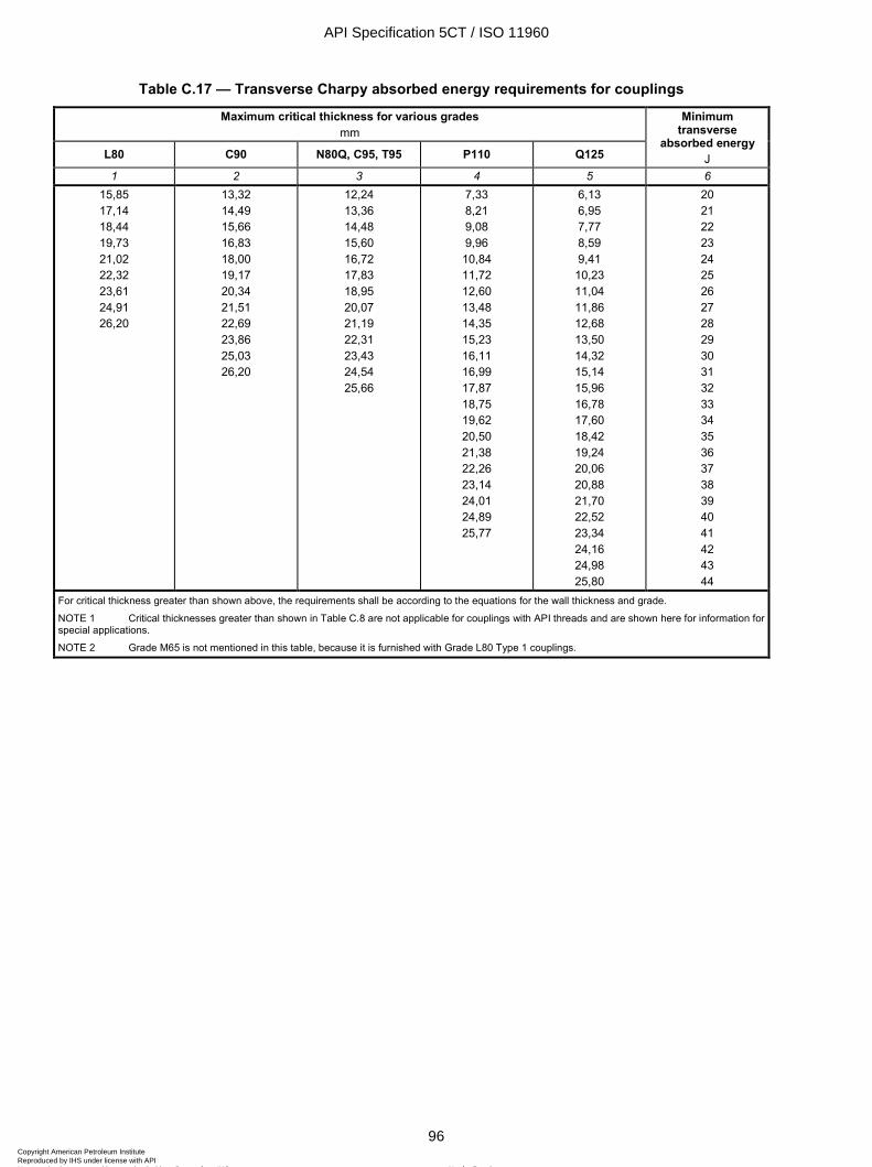
ISO 11960:2004(E)
96 © ISO 2004 – All rights reserved
Table C.17 — Transverse Charpy absorbed energy requirements for couplings
Maximum critical thickness for various grades mm
L80 C90 N80Q, C95, T95 P110 Q125
Minimum transverse
absorbed energy J
1 2 3 4 5 6 15,85 17,14 18,44 19,73 21,02 22,32 23,61 24,91 26,20
13,32 14,49 15,66 16,83 18,00 19,17 20,34 21,51 22,69 23,86 25,03 26,20
12,24 13,36 14,48 15,60 16,72 17,83 18,95 20,07 21,19 22,31 23,43 24,54 25,66
7,33 8,21 9,08 9,96 10,84 11,72 12,60 13,48 14,35 15,23 16,11 16,99 17,87 18,75 19,62 20,50 21,38 22,26 23,14 24,01 24,89 25,77
6,13 6,95 7,77 8,59 9,41 10,23 11,04 11,86 12,68 13,50 14,32 15,14 15,96 16,78 17,60 18,42 19,24 20,06 20,88 21,70 22,52 23,34 24,16 24,98 25,80
20 21 22 23 24 25 26 27 28 29 30 31 32 33 34 35 36 37 38 39 40 41 42 43 44
For critical thickness greater than shown above, the requirements shall be according to the equations for the wall thickness and grade.
NOTE 1 Critical thicknesses greater than shown in Table C.8 are not applicable for couplings with API threads and are shown here for information for special applications.
NOTE 2 Grade M65 is not mentioned in this table, because it is furnished with Grade L80 Type 1 couplings.
API Specification 5CT / ISO 11960
96Copyright American Petroleum Institute Reproduced by IHS under license with API
Not for ResaleNo reproduction or networking permitted without license from IHS
--`,,,```-`-`,,`,,`,`,,`---
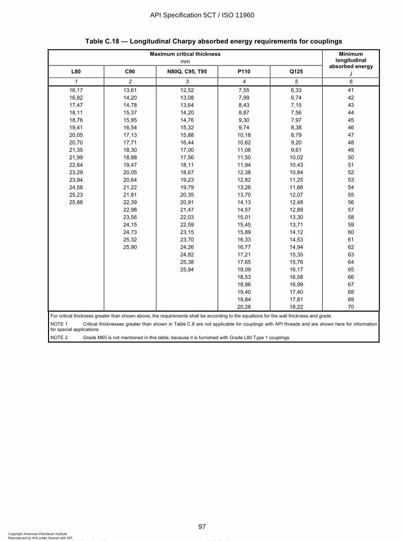
ISO 11960:2004(E)
© ISO 2004 – All rights reserved 97
Table C.18 — Longitudinal Charpy absorbed energy requirements for couplings
Maximum critical thickness mm
L80 C90 N80Q, C95, T95 P110 Q125
Minimum longitudinal
absorbed energy J
1 2 3 4 5 6 16,17 16,82 17,47 18,11 18,76 19,41 20,05 20,70 21,35 21,99 22,64 23,29 23,94 24,58 25,23 25,88
13,61 14,20 14,78 15,37 15,95 16,54 17,13 17,71 18,30 18,88 19,47 20,05 20,64 21,22 21,81 22,39 22,98 23,56 24,15 24,73 25,32 25,90
12,52 13,08 13,64 14,20 14,76 15,32 15,88 16,44 17,00 17,56 18,11 18,67 19,23 19,79 20,35 20,91 21,47 22,03 22,59 23,15 23,70 24,26 24,82 25,38 25,94
7,55 7,99 8,43 8,87 9,30 9,74 10,18 10,62 11,06 11,50 11,94 12,38 12,82 13,26 13,70 14,13 14,57 15,01 15,45 15,89 16,33 16,77 17,21 17,65 18,09 18,53 18,96 19,40 19,84 20,28
6,33 6,74 7,15 7,56 7,97 8,38 8,79 9,20 9,61 10,02 10,43 10,84 11,25 11,66 12,07 12,48 12,89 13,30 13,71 14,12 14,53 14,94 15,35 15,76 16,17 16,58 16,99 17,40 17,81 18,22
41 42 43 44 45 46 47 48 49 50 51 52 53 54 55 56 57 58 59 60 61 62 63 64 65 66 67 68 69 70
For critical thickness greater than shown above, the requirements shall be according to the equations for the wall thickness and grade.
NOTE 1 Critical thicknesses greater than shown in Table C.8 are not applicable for couplings with API threads and are shown here for information for special applications.
NOTE 2 Grade M65 is not mentioned in this table, because it is furnished with Grade L80 Type 1 couplings.
API Specification 5CT / ISO 11960
97Copyright American Petroleum Institute Reproduced by IHS under license with API
Not for ResaleNo reproduction or networking permitted without license from IHS
--`,,,```-`-`,,`,,`,`,,`---
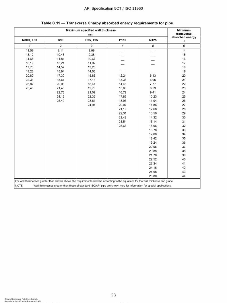
ISO 11960:2004(E)
98 © ISO 2004 – All rights reserved
Table C.19 — Transverse Charpy absorbed energy requirements for pipe
Maximum specified wall thickness mm
N80Q, L80 C90 C95, T95 P110 Q125
Minimum transverse
absorbed energy J
1 2 3 4 5 6 11,59 13,12 14,66 16,19 17,73 19,26 20,80 22,33 23,87 25,40
9,11 10,48 11,84 13,21 14,57 15,94 17,30 18,67 20,03 21,40 22,76 24,12 25,49
8,09 9,38 10,67 11,97 13,26 14,56 15,85 17,14 18,44 19,73 21,02 22,32 23,61 24,91
__ __ __ __ __ __
12,24 13,36 14,48 15,60 16,72 17,83 18,95 20,07 21,19 22,31 23,43 24,54 25,66
__ __ __ __ __ __
6,13 6,95 7,77 8,59 9,41 10,23 11,04 11,86 12,68 13,50 14,32 15,14 15,96 16,78 17,60 18,42 19,24 20,06 20,88 21,70 22,52 23,34 24,16 24,98 25,80
14 15 16 17 18 19 20 21 22 23 24 25 26 27 28 29 30 31 32 33 34 35 36 37 38 39 40 41 42 43 44
For wall thicknesses greater than shown above, the requirements shall be according to the equations for the wall thickness and grade.
NOTE Wall thicknesses greater than those of standard ISO/API pipe are shown here for information for special applications.
API Specification 5CT / ISO 11960
98Copyright American Petroleum Institute Reproduced by IHS under license with API
Not for ResaleNo reproduction or networking permitted without license from IHS
--`,,,```-`-`,,`,,`,`,,`---
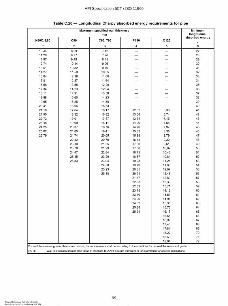
ISO 11960:2004(E)
© ISO 2004 – All rights reserved 99
Table C.20 — Longitudinal Charpy absorbed energy requirements for pipe
Maximum specified wall thickness mm
N80Q, L80 C90 C95, T95 P110 Q125
Minimum longitudinal
absorbed energy J
1 2 3 4 5 6 10,44 11,20 11,97 12,74 13,51 14,27 15,04 15,81 16,58 17,34 18,11 18,88 19,65 20,41 21,18 21,95 22,72 23,48 24,25 25,02 25,79
8,09 8,77 9,45
10,14 10,82 11,50 12,18 12,87 13,55 14,23 14,91 15,60 16,28 16,96 17,64 18,32 19,01 19,69 20,37 21,05 21,74 22,42 23,10 23,78 24,47 25,15 25,83
7,12 7,76 8,41 9,06 9,70 10,35 11,00 11,64 12,29 12,94 13,58 14,23 14,88 15,53 16,17 16,82 17,47 18,11 18,76 19,41 20,05 20,70 21,35 21,99 22,64 23,29 23,94 24,58 25,23 25,88
— — — — — — — — — — — — — —
12,52 13,08 13,64 14,20 14,76 15,32 15,88 16,44 17,00 17,56 18,11 18,67 19,23 19,79 20,35 20,91 21,47 22,03 22,59 23,15 23,70 24,26 24,82 25,38 25,94
— — — — — — — — — — — — — —
6,33 6,74 7,15 7,56 7,97 8,38 8,79 9,20 9,61 10,02 10,43 10,84 11,25 11,66 12,07 12,48 12,89 13,30 13,71 14,12 14,53 14,94 15,35 15,76 16,17 16,58 16,99 17,40 17,81 18,22 18,63 19,04
27 28 29 30 31 32 33 34 35 36 37 38 39 40 41 42 43 44 45 46 47 48 49 50 51 52 53 54 55 56 57 58 59 60 61 62 63 64 65 66 67 68 69 70 71 72
For wall thicknesses greater than shown above, the requirements shall be according to the equations for the wall thickness and grade.
NOTE Wall thicknesses greater than those of standard ISO/API pipe are shown here for information for special applications.
API Specification 5CT / ISO 11960
99Copyright American Petroleum Institute Reproduced by IHS under license with API
Not for ResaleNo reproduction or networking permitted without license from IHS
--`,,,```-`-`,,`,,`,`,,`---
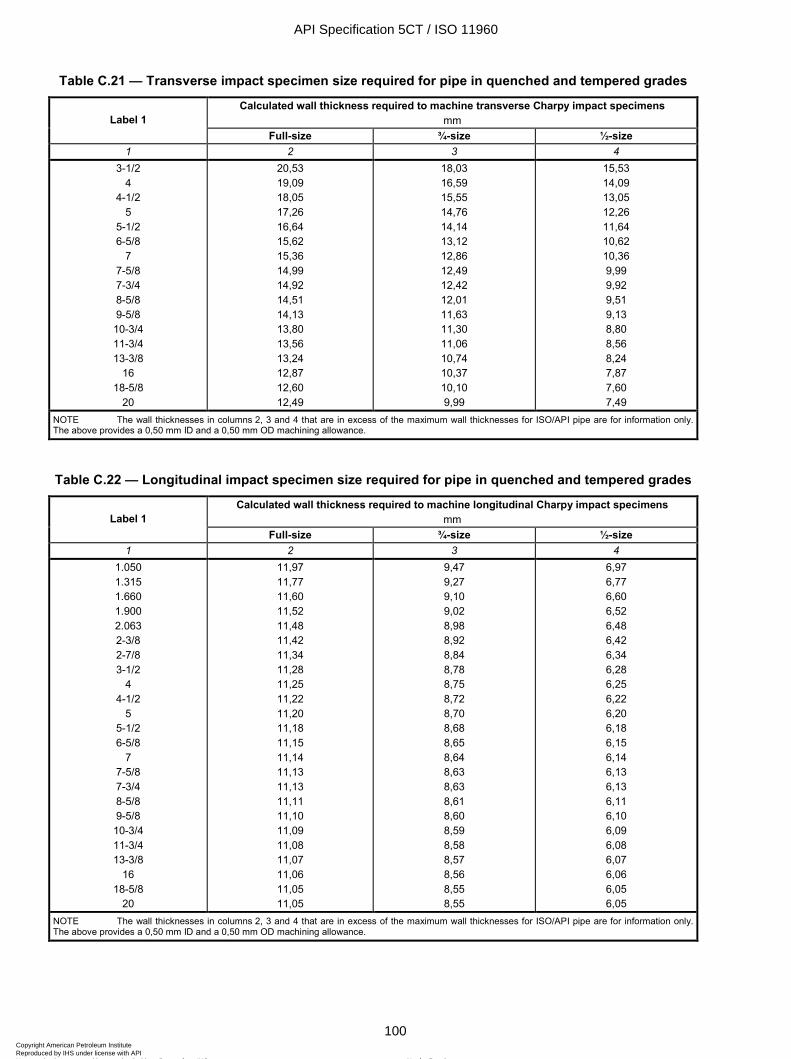
ISO 11960:2004(E)
100 © ISO 2004 – All rights reserved
Table C.21 — Transverse impact specimen size required for pipe in quenched and tempered grades
Calculated wall thickness required to machine transverse Charpy impact specimens mm Label 1
Full-size ¾-size ½-size 1 2 3 4
3-1/2 4
4-1/2 5
5-1/2 6-5/8
7 7-5/8 7-3/4 8-5/8 9-5/8 10-3/4 11-3/4 13-3/8
16 18-5/8
20
20,53 19,09 18,05 17,26 16,64 15,62 15,36 14,99 14,92 14,51 14,13 13,80 13,56 13,24 12,87 12,60 12,49
18,03 16,59 15,55 14,76 14,14 13,12 12,86 12,49 12,42 12,01 11,63 11,30 11,06 10,74 10,37 10,10 9,99
15,53 14,09 13,05 12,26 11,64 10,62 10,36 9,99 9,92 9,51 9,13 8,80 8,56 8,24 7,87 7,60 7,49
NOTE The wall thicknesses in columns 2, 3 and 4 that are in excess of the maximum wall thicknesses for ISO/API pipe are for information only. The above provides a 0,50 mm ID and a 0,50 mm OD machining allowance.
Table C.22 — Longitudinal impact specimen size required for pipe in quenched and tempered grades
Calculated wall thickness required to machine longitudinal Charpy impact specimens mm Label 1
Full-size ¾-size ½-size 1 2 3 4
1.050 1.315 1.660 1.900 2.063 2-3/8 2-7/8 3-1/2
4 4-1/2
5 5-1/2 6-5/8
7 7-5/8 7-3/4 8-5/8 9-5/8 10-3/4 11-3/4 13-3/8
16 18-5/8
20
11,97 11,77 11,60 11,52 11,48 11,42 11,34 11,28 11,25 11,22 11,20 11,18 11,15 11,14 11,13 11,13 11,11 11,10 11,09 11,08 11,07 11,06 11,05 11,05
9,47 9,27 9,10 9,02 8,98 8,92 8,84 8,78 8,75 8,72 8,70 8,68 8,65 8,64 8,63 8,63 8,61 8,60 8,59 8,58 8,57 8,56 8,55 8,55
6,97 6,77 6,60 6,52 6,48 6,42 6,34 6,28 6,25 6,22 6,20 6,18 6,15 6,14 6,13 6,13 6,11 6,10 6,09 6,08 6,07 6,06 6,05 6,05
NOTE The wall thicknesses in columns 2, 3 and 4 that are in excess of the maximum wall thicknesses for ISO/API pipe are for information only. The above provides a 0,50 mm ID and a 0,50 mm OD machining allowance.
API Specification 5CT / ISO 11960
100Copyright American Petroleum Institute Reproduced by IHS under license with API
Not for ResaleNo reproduction or networking permitted without license from IHS
--`,,,```-`-`,,`,,`,`,,`---
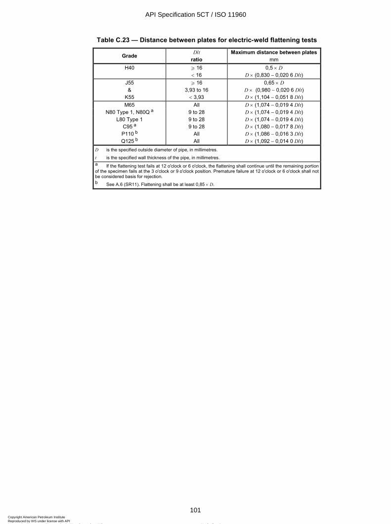
ISO 11960:2004(E)
© ISO 2004 – All rights reserved 101
Table C.23 — Distance between plates for electric-weld flattening tests
Grade D/t ratio
Maximum distance between plates mm
H40 W 16 < 16
0,5 × D D × (0,830 - 0,020 6 D/t)
J55 &
K55
W 16 3,93 to 16 < 3,93
0,65 × D D × (0,980 - 0,020 6 D/t) D × (1,104 - 0,051 8 D/t)
M65 All D × (1,074 - 0,019 4 D/t) N80 Type 1, N80Q a 9 to 28 D × (1,074 - 0,019 4 D/t)
L80 Type 1 C95 a P110 b Q125 b
9 to 28 9 to 28
All All
D × (1,074 - 0,019 4 D/t) D × (1,080 - 0,017 8 D/t) D × (1,086 - 0,016 3 D/t) D × (1,092 - 0,014 0 D/t)
D is the specified outside diameter of pipe, in millimetres.
t is the specified wall thickness of the pipe, in millimetres. a If the flattening test fails at 12 o'clock or 6 o'clock, the flattening shall continue until the remaining portion of the specimen fails at the 3 o'clock or 9 o'clock position. Premature failure at 12 o'clock or 6 o'clock shall not be considered basis for rejection. b See A.6 (SR11). Flattening shall be at least 0,85 × D.
API Specification 5CT / ISO 11960
101Copyright American Petroleum Institute Reproduced by IHS under license with API
Not for ResaleNo reproduction or networking permitted without license from IHS
--`,,,```-`-`,,`,,`,`,,`---

ISO 11960:2004(E)
102 © ISO 2004 – All rights reserved
Table C.24 — Dimensions and masses for standard casing and for casing threaded with API round thread, buttress thread and extreme-line connections
Calculated mass c em, mass gain or loss due to end finishing d
kg Labels a Outside diameter
Nominal linear mass
T&C b, c
Wall thick-ness
Inside diam-eter
Drift diam-eter
Plain end
Round thread Buttress thread Extreme-line
1 2 D
mm kg/m t
mm d
mm mm wpe kg/m
Short Long Reg. OD SCC Standard Optional
1 2 3 4 5 6 7 8 9 10 11 12 13 14 4-1/2 4-1/2 4-1/2 4-1/2 4-1/2
9.50 10.50 11.60 13.50 15.10
114,30 114,30 114,30 114,30 114,30
14,14 15,63 17,26 20,09 22,47
5,21 5,69 6,35 7,37 8,56
103,88 102,92 101,60 99,56 97,18
100,70 99,74 98,42 96,38 94,00
14,02 15,24 16,91 19,44 22,32
1,91 1,72 1,54 — —
— —
1,72 1,45 1,27
— 2,27 2,09 1,81 1,45
— 1,16 0,98 0,71 0,34
— — — — —
— — — —
5 5 5 5 5 5 5
11.50 13.00 15.00 18.00 21.40 23.20 24.10
127,00 127,00 127,00 127,00 127,00 127,00 127,00
17,11 19,35 22,32 26,79 31,85 34,53 35,86
5,59 6,43 7,52 9,19 11,10 12,14 12,70
115,82 114,14 111,96 108,62 104,80 102,72 101,60
112,64 110,96 108,78 105,44 101,62 99,54 98,42
16,74 19,12 22,16 26,70 31,73 34,39 35,80
2,45 2,18 1,91 — — — —
— 2,63 2,36 1,91 1,34 1,04 0,88
— 2,99 2,63 2,00 1,12 0,93 0,56
— 1,10 0,73 0,,10 -0,78 -0,95 -1,33
— —
2,09 0,64 — — —
— — — — — — —
5-1/2 5-1/2 5-1/2 5-1/2 5-1/2 5-1/2 5-1/2 5-1/2 5-1/2 5-1/2 5-1/2 5-1/2
14.00 15.50 17.00 20.00 23.00 26.80 29.70 32.60 35.30 38.00 40.50 43.10
139,70 139,70 139,70 139,70 139,70 139,70 139,70 139,70 139,70 139,70 139,70 139,70
20,83 23,07 25,30 29,76 34,23 39,88 44,20 48,51 52,53 56,55 60,27 64,14
6,20 6,98 7,72 9,17 10,54 12,70 14,27 15,88 17,45 19,05 20,62 22,22
127,30 125,74 124,26 121,36 118,62 114,30 111,16 107,94 104,80 101,60 98,46 95,26
124,12 122,56 121,08 118,18 115,44 111,12 107,98 104,76 101,62 98,42 95,28 92,08
20,41 22,85 25,13 29,52 33,57 39,78 44,14 48,49 52,61 56,68 60,55 64,38
2,45 2,18 2,00 — — — — — — — — —
— 2,63 2,45 2,00 1,45 — — — — — — —
— 2,90 2,63 2,09 1,54 — — — — — — —
— 0,95 0,68 0,14 -0,41
— — — — — — —
— 2,63 2,18 0,64 0,00 — — — — — — —
— 1,91 1,45 -0,09 -0,73
— — — — — — —
6-5/8 6-5/8 6-5/8 6-5/8
20.00 24.00 28.00 32.00
168,28 168,28 168,28 168,28
29,76 35,72 41,67 47,62
7,32 8,94 10,59 12,06
153,64 150,40 147,10 144,16
150,46 147,22 143,92 140,98
29,06 35,13 41,18 46,46
4,99 4,35 — —
6,17 5,44 4,63 3,99
6,53 5,72 4,81 4,08
1,08 0,26 -0,64 -1,37
— 1,54 0,09 -0,64
— 0,82 -0,64 -1,36
7 7 7 7 7 7 7 7 7 7 7 7 7 7 7
17.00 20.00 23.00 23.00 26.00 29.00 32.00 32.00 35.00 38.00 42.70 46.40 50.10 53.60 57.10
177,80 177,80 177,80 177,80 177,80 177,80 177,80 177,80 177,80 177,80 177,80 177,80 177,80 177,80 177,80
25,30 29,76 34,23 34,23 38,69 43,16 47,62 47,62 52,09 56,55 63,54 69,05 74,56 79,77 84,97
5,87 6,91 8,05 8,05 9,19 10,36 11,51 11,51 12,65 13,72 15,88 17,45 19,05 20,62 22,22
166,06 163,98 161,70 161,70 159,42 157,08 154,78 154,78 152,50 150,36 146,04 142,90 139,70 136,56 133,36
162,88 160,80
158,75 e
158,52 156,24 153,90
152,40 e
151,60 149,32 147,18 142,86 139,72 136,52 133,38 130,18
24,89 29,12 33,70 33,70 38,21 42,78 47,20 47,20 51,52 55,52 63,41 69,01 74,58 79,93 85,25
4,54 4,26 3,63 3,63 3,27 — — — — — — — — — —
— —
4,72 4,72 4,26 3,63 2,99 2,99 2,54 2,00 — — — — —
— —
4,99 4,99 4,35 3,72 3,08 3,08 2,54 1,91 — — — — —
— —
0,73 0,73 0,09 -0,54 -1,18 -1,18 -1,72 -2,36
— — — — —
— —
2,72 2,72 1,27 0,27 -0,27 -0,27 0,45 -0,09
— — — — —-
— —
1,91 1,91 0,45 -0,54 -1,09 -1,09 -0,82 -1,36
— — — — —
See notes at end of table.
API Specification 5CT / ISO 11960
102Copyright American Petroleum Institute Reproduced by IHS under license with API
Not for ResaleNo reproduction or networking permitted without license from IHS
--`,,,```-`-`,,`,,`,`,,`---
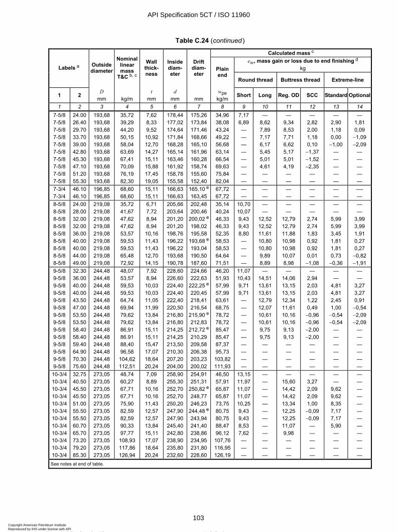
ISO 11960:2004(E)
© ISO 2004 – All rights reserved 103
Table C.24 (continued)
Calculated mass c em, mass gain or loss due to end finishing d
kg Labels a Outside diameter
Nominal linear mass
T&C b, c
Wall thick-ness
Inside diam-eter
Drift diam-eter
Plain end
Round thread Buttress thread Extreme-line
1 2 D
mm kg/m t
mm d
mm mm wpe kg/m
Short Long Reg. OD SCC Standard Optional
1 2 3 4 5 6 7 8 9 10 11 12 13 14 7-5/8 7-5/8 7-5/8 7-5/8 7-5/8 7-5/8 7-5/8 7-5/8 7-5/8 7-5/8
24.00 26.40 29.70 33.70 39.00 42.80 45.30 47.10 51.20 55.30
193,68 193,68 193,68 193,68 193,68 193,68 193,68 193,68 193,68 193,68
35,72 39,29 44,20 50,15 58,04 63,69 67,41 70,09 76,19 82,30
7,62 8,33 9,52 10,92 12,70 14,27 15,11 15,88 17,45 19,05
178,44 177,02 174,64 171,84 168,28 165,14 163,46 161,92 158,78 155,58
175,26 173,84 171,46 168,66 165,10 161,96 160,28 158,74 155,60 152,40
34,96 38,08 43,24 49,22 56,68 63,14 66,54 69,63 75,84 82,04
7,17 6,89 — — — — — — — —
— 8,62 7,89 7,17 6,17 5,45 5,01 4,61 — —
— 9,34 8,53 7,71 6,62 5,17 5,01 4,19 — —
— 2,82 2,00 1,18 0,10 -1,37 -1,52 -2,35
— —
— 2,90 1,18 0,00 -1,00
— — — — —
— 1,81 0,09 -1,09 -2,09
— — — — —
7-3/4 7-3/4
46.10 46.10
196,85 196,85
68,60 68,60
15,11 15,11
166,63 166,63
165,10 e
163,45 67,72 67,72
— —
— —
— —
— —
— —
—- —
8-5/8 8-5/8 8-5/8 8-5/8 8-5/8 8-5/8 8-5/8 8-5/8 8-5/8
24.00 28.00 32.00 32.00 36.00 40.00 40.00 44.00 49.00
219,08 219,08 219,08 219,08 219,08 219,08 219,08 219,08 219,08
35,72 41,67 47,62 47,62 53,57 59,53 59,53 65,48 72,92
6,71 7,72 8,94 8,94 10,16 11,43 11,43 12,70 14,15
205,66 203,64 201,20 201,20 198,76 196,22 196,22 193,68 190,78
202,48 200,46
200,02 e
198,02 195,58
193,68 e
193,04 190,50 187,60
35,14 40,24 46,33 46,33 52,35 58,53 58,53 64,64 71,51
10,7010,079,43 9,43 8,80 — — — —
— —
12,52 12,52 11,61 10,80 10,80 9,89 8,89
— —
12,79 12,79 11,88 10,98 10,98 10,07 8,98
— —
2,74 2,74 1,83 0,92 0,92 0,01 -1,08
— —
5,99 5,99 3,45 1,81 1,81 0,73 -0,36
— —
3,99 3,99 1,91 0,27 0,27 -0,82 -1,91
9-5/8 9-5/8 9-5/8 9-5/8 9-5/8 9-5/8 9-5/8 9-5/8 9-5/8 9-5/8 9-5/8 9-5/8 9-5/8 9-5/8
32.30 36.00 40.00 40.00 43.50 47.00 53.50 53.50 58.40 58.40 59.40 64.90 70.30 75.60
244,48 244,48 244,48 244,48 244,48 244,48 244,48 244,48 244,48 244,48 244,48 244,48 244,48 244,48
48,07 53,57 59,53 59,53 64,74 69,94 79,62 79,62 86,91 86.91 88,40 96,58 104,62 112,51
7,92 8,94 10,03 10,03 11,05 11,99 13,84 13,84 15,11 15,11 15,47 17,07 18,64 20,24
228,60 226,60 224,40 224,40 222,40 220,50 216,80 216,80 214,25 214,25 213,50 210,30 207,20 204,00
224,66 222,63
222,25 e
220,45 218,41 216,54
215,90 e
212,83 212,72 e
210,29 209,58 206,38 203,23 200,02
46,20 51,93 57,99 57,99 63,61 68,75 78,72 78,72 85,47 85,47 87,37 95,73 103,82 111,93
11,0710,439,71 9,71 — — — — — — — — — —
— 14,51 13,61 13,61 12,79 12,07 10,61 10,61 9,75 9,75 — — — —
— 14,06 13,15 13,15 12,34 11,61 10,16 10,16 9,13 9,13 — — — —
— 2,94 2,03 2,03 1,22 0,49 -0,96 -0,96 -2,00 -2,00
— — — —
— —
4,81 4,81 2,45 1,00 -0,54 -0,54
— — — — — —
— —
3,27 3,27 0,91 -0,54 -2,09 -2,09
— — — — — —
10-3/4 10-3/4 10-3/4 10-3/4 10-3/4 10-3/4 10-3/4 10-3/4 10-3/4 10-3/4 10-3/4 10-3/4
32.75 40.50 45.50 45.50 51.00 55.50 55.50 60.70 65.70 73.20 79.20 85.30
273,05 273,05 273,05 273,05 273,05 273,05 273,05 273,05 273,05 273,05 273,05 273,05
48,74 60,27 67,71 67,71 75,90 82,59 82,59 90,33 97,77 108,93 117,86 126,94
7,09 8,89 10,16 10,16 11,43 12,57 12,57 13,84 15,11 17,07 18,64 20,24
258,90 255,30 252,70 252,70 250,20 247,90 247,90 245,40 242,80 238,90 235,80 232,60
254,91 251,31
250,82 e
248,77 246,23
244,48 e
243,94 241,40 238,86 234,95 231,80 228,60
46,50 57,91 65,87 65,87 73,75 80,75 80,75 88,47 96,12 107,76 116,95 126,19
13,1511,9711,0711,0710,259,43 9,43 8,53 7,62 — — —
— — — — — — — — — — — —
— 15,60 14,42 14,42 13,34 12,25 12,25 11,07 9,98 — — —
— 3,27 2,09 2,09 1,00 -0,09 -0,09
— — — — —
— —
9,62 9,62 8,35 7,17 7,17 5,90 — — — —
— — — — — — — — — — — —
See notes at end of table.
API Specification 5CT / ISO 11960
103Copyright American Petroleum Institute Reproduced by IHS under license with API
Not for ResaleNo reproduction or networking permitted without license from IHS
--`,,,```-`-`,,`,,`,`,,`---
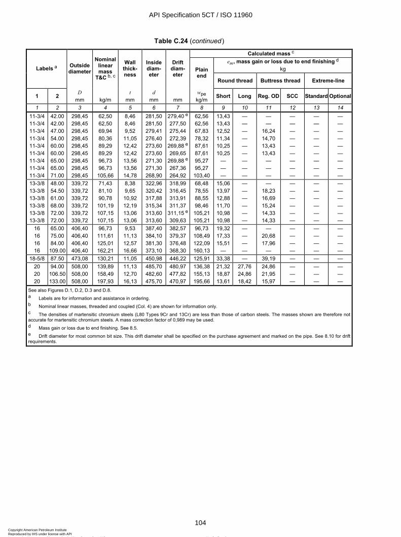
ISO 11960:2004(E)
104 © ISO 2004 – All rights reserved
Table C.24 (continued)
Calculated mass c em, mass gain or loss due to end finishing d
kg Labels a Outside diameter
Nominal linear mass
T&C b, c
Wall thick-ness
Inside diam-eter
Drift diam-eter
Plain end
Round thread Buttress thread Extreme-line
1 2 D
mm kg/m t
mm d
mm mm wpe kg/m
Short Long Reg. OD SCC Standard Optional
1 2 3 4 5 6 7 8 9 10 11 12 13 14 11-3/4 11-3/4 11-3/4 11-3/4 11-3/4 11-3/4 11-3/4 11-3/4 11-3/4
42.00 42.00 47.00 54.00 60.00 60.00 65.00 65.00 71.00
298,45 298,45 298,45 298,45 298,45 298,45 298,45 298,45 298,45
62,50 62,50 69,94 80,36 89,29 89,29 96,73 96,73 105,66
8,46 8,46 9,52 11,05 12,42 12,42 13,56 13,56 14,78
281,50 281,50 279,41 276,40 273,60 273,60 271,30 271,30 268,90
279,40 e
277,50 275,44 272,39
269,88 e
269,65 269,88 e
267,36 264,92
62,56 62,56 67,83 78,32 87,61 87,61 95,27 95,27 103,40
13,4313,4312,5211,3410,2510,25
— — —
— — — — — — — — —
— —
16,24 14,70 13,43 13,43
— — —
— — — — — — — — —
— — — — — — — — —
— — — — — — — — —
13-3/8 13-3/8 13-3/8 13-3/8 13-3/8 13-3/8
48.00 54.50 61.00 68.00 72.00 72.00
339,72 339,72 339,72 339,72 339,72 339,72
71,43 81,10 90,78 101,19 107,15 107,15
8,38 9,65 10,92 12,19 13,06 13,06
322,96 320,42 317,88 315,34 313,60 313,60
318,99 316,45 313,91 311,37
311,15 e
309,63
68,48 78,55 88,55 98,46 105,21 105,21
15,0613,9712,8811,7010,9810,98
— — — — — —
— 18,23 16,69 15,24 14,33 14,33
— — — — — —
— — — — — —
— — — — — —
16 16 16 16
65.00 75.00 84.00
109.00
406,40 406,40 406,40 406,40
96,73 111,61 125,01 162,21
9,53 11,13 12,57 16,66
387,40 384,10 381,30 373,10
382,57 379,37 376,48 368,30
96,73 108,49 122,09 160,13
19,3217,3315,51
—
— — — —
— 20,68 17,96
—
— — — —
— — — —
— — — —
18-5/8 87.50 473,08 130,21 11,05 450,98 446,22 125,91 33,38 — 39,19 — — — 20 20 20
94.00 106.50 133.00
508,00 508,00 508,00
139,89 158,49 197,93
11,13 12,70 16,13
485,70 482,60 475,70
480,97 477,82 470,97
136,38 155,13 195,66
21,3218,8713,61
27,76 24,86 18,42
24,86 21,95 15,97
— — —
— — —
— — —
See also Figures D.1, D.2, D.3 and D.8. a Labels are for information and assistance in ordering. b Nominal linear masses, threaded and coupled (Col. 4) are shown for information only. c The densities of martensitic chromium steels (L80 Types 9Cr and 13Cr) are less than those of carbon steels. The masses shown are therefore not accurate for martensitic chromium steels. A mass correction factor of 0,989 may be used. d Mass gain or loss due to end finishing. See 8.5. e Drift diameter for most common bit size. This drift diameter shall be specified on the purchase agreement and marked on the pipe. See 8.10 for drift requirements.
API Specification 5CT / ISO 11960
104Copyright American Petroleum Institute Reproduced by IHS under license with API
Not for ResaleNo reproduction or networking permitted without license from IHS
--`,,,```-`-`,,`,,`,`,,`---
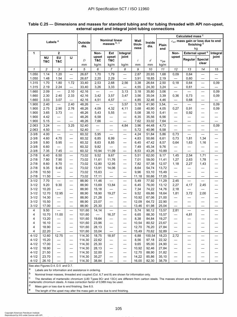
ISO 11960:2004(E)
© ISO 2004 – All rights reserved 105
Table C.25 — Dimensions and masses for standard tubing and for tubing threaded with API non-upset, external upset and integral joint tubing connections
Calculated mass c
Labels a Nominal linear masses b, c
em, mass gain or loss due to end finishing d
kg 1 2
Outside dia.
Wall thick-ness
Inside dia. Plain
end External upset e
NU T&C
EU T&C
IJ D
mm
Non-upset T&C kg/m
Ext upset T&C kg/m
Integral joint
kg/m
t mm
d mm
wpe kg/m
Non-upset
Regular
Special clear
Integral joint
1 2 3 4 5 6 7 8 9 10 11 12 13 14 15 1.050 1.050
1.14 1.48
1.20 1.54
— —
26,67 26,67
1,70 2,20
1,79 2,29
— —
2,87 3,91
20,93 18,85
1,68 2,19
0,09 —
0,64 0,60
— —
— —
1.315 1.315
1.70 2.19
1.80 2.24
1.72 —
33,40 33,40
2,53 3,26
2,68 3,33
2,56 —
3,38 4,55
26,64 24,30
2,50 3,24
0,18 —
0,64 0,61
— —
0,09 —
1.660 1.660 1.660
2.09 2.30 3.03
— 2.40 3.07
2.10 2.33 —
42,16 42,16 42,16
— 3,42 4,51
— 3,57 4,57
3,13 3,47 —
3,18 3,56 4,85
35,80 35,04 32,46
3,06 3,39 4,46
— 0,36 —
— 0,73 0,68
— — —
0,09 0,09 —
1.900 1.900 1.900 1.900 1.900
2.40 2.75 3.65 4.42 5.15
— 2.90 3.73 — —
2.40 2.76 — — —
48,26 48,26 48,26 48,26 48,26
— 4,09 5,43 6,58 7,66
— 4,32 5,55 — —
3,57 4,11 — — —
3,18 3,68 5,08 6,35 7,62
41,90 40,90 38,10 35,56 33,02
3,54, 4,05 5,41 6,56 7,64
— 0,27 — — —
— 0,91 0,92 — —
— — — — —
0,09 0,09 — — —
2.063 2.063
3.24 4.50
— —
3.25 —
52,40 52,40
— —
— —
4,84 —
3,96 5,72
44,48 40,96
4,73 6,58
— —
— —
— —
0,09 —
2-3/8 2-3/8 2-3/8 2-3/8 2-3/8
4.00 4.60 5.80 6.60 7.35
— 4.70 5.95 —
7.45
— — — — —
60,32 60,32 60,32 60,32 60,32
5,95 6,85 8,63 9,82
10,94
— 6,99 8,85 —
11,09
— — — — —
4,24 4,83 6,45 7,49 8,53
51,84 50,66 47,42 45,34 43,26
5,86 6,61 8,57 9,76 10,89
0,73 0,73 0,64 — —
— 1,81 1,63 — —
— 1,34 1,16 — —
— — — — —
2-7/8 2-7/8 2-7/8 2-7/8 2-7/8 2-7/8
6.40 7.80 8.60 9.35 10.50 11.50
6.50 7.90 8.70 9.45 — —
— — — — — —
73,02 73,02 73,02 73,02 73,02 73,02
9,52 11,61 12,80 13,91 15,63 17,11
9,67 11,76 12,95 14,06
— —
— — — — — —
5,51 7,01 7,82 8,64 9,96 11,18
62,00 59,00 57,38 54,74 53,10 50,66
9,17 11,41 12,57 13,72 15,49 17,05
1,45 1,27 1,18 — — —
2,54 2,63 2,27 — — —
1,71 1,78 1,43 — — —
— — — — — —
3-1/2 3-1/2 3-1/2 3-1/2 3-1/2 3-1/2 3-1/2
7.70 9.20 10.20 12.70 14.30 15.50 17.00
— 9.30 —
12.95 — — —
— — — — — — —
88,90 88,90 88,90 88,90 88,90 88,90 88,90
11,46 13,69 15,18 18,90 21,28 23,07 25,30
— 13,84
— 19,27
— — —
— — — — — — —
5,49 6,45 7,34 9,52 10,92 12,09 13,46
77,92 76,00 74,22 69,86 67,06 64,72 61,98
11,29 13,12 14,76 18,64 21,00 22,90 25,04
2,45 2,27 2,18 1,81 — — —
— 4,17 —
3,72 — — —
— 2,45 —
2,00 — — —
— — — — — — —
4 4 4 4 4 4
9.50 10.70 13.20 16.10 18.90 22.20
— 11.00
— — — —
— — — — — —
101,60 101,60 101,60 101,60 101,60 101,60
14,14 —
19,64 23,96 28,13 33,04
— 16,37
— — — —
— — — — — —
5,74 6,65 8,38 10,54 12,70 15,49
90,12 88,30 84,84 80,52 76,20 70,62
13,57 15,57 19,27 23,67 27,84 32,89
2,81 — — — — —
— 4,81 — — — —
— — — — — —
— — — — — —
4-1/2 4-1/2 4-1/2 4-1/2 4-1/2 4-1/2 4-1/2
12.60 15.20 17.00 18.90 21.50 23.70 26.10
12.75 — — — — — —
— — — — — — —
114,30 114,30 114,30 114,30 114,30 114,30 114,30
18,75 22,62 25,30 28,13 32,00 35,27 38,84
18,97 — — — — — —
— — — — — — —
6,88 8,56 9,65 10,92 12,70 14,22 16,00
100,5497,18 95,00 92,46 88,90 85,86 82,30
18,23 22,32 24,90 27,84 31,82 35,10 38,79
2,72 — — — — — —
— — — — — — —
— — — — — — —
— — — — — — —
See also Figures D.4, D.5 and D.7. a Labels are for information and assistance in ordering. b Nominal linear masses, threaded and coupled (Col. 6,7 and 8) are shown for information only. c The densities of martensitic chromium (L80 Types 9Cr and 13Cr) are different from carbon steels. The masses shown are therefore not accurate for martensitic chromium steels. A mass correction factor of 0,989 may be used. d Mass gain or loss due to end finishing. See 8.5. e The length of the upset may alter the mass gain or loss due to end finishing.
API Specification 5CT / ISO 11960
105Copyright American Petroleum Institute Reproduced by IHS under license with API
Not for ResaleNo reproduction or networking permitted without license from IHS
--`,,,```-`-`,,`,,`,`,,`---
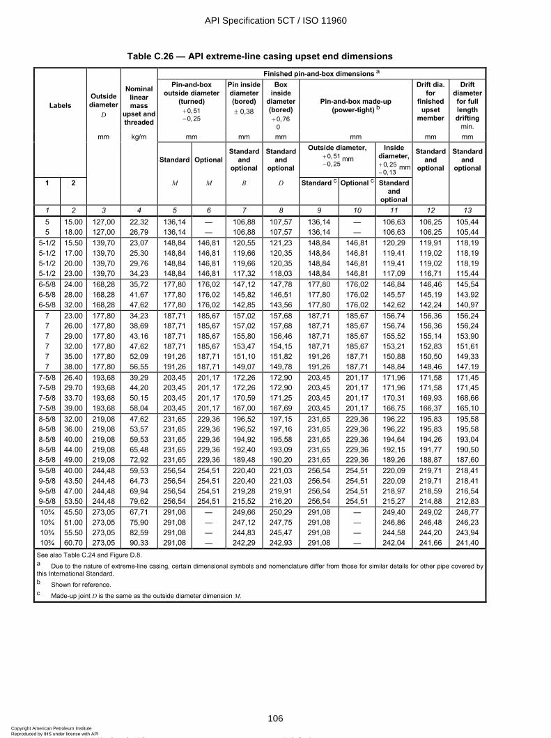
ISO 11960:2004(E)
106 © ISO 2004 – All rights reserved
Table C.26 — API extreme-line casing upset end dimensions
Finished pin-and-box dimensions a
Labels Outside diameter
D
Nominal linear mass
upset and threaded
Pin-and-box outside diameter
(turned) 0,510, 25
+−
Pin inside diameter (bored) ± 0,38
Box inside
diameter (bored)
0,760
+
Pin-and-box made-up (power-tight) b
Drift dia. for
finished upset
member
Drift diameter for full length drifting
min. mm kg/m mm mm mm mm mm mm
Standard Optional Standard
and optional
Standard and
optional
Outside diameter, 0,510, 25
+−
mm Inside
diameter, 0, 250,13
+−
mm
Standard and
optional
Standard and
optional
1 2 M M B D Standard c Optional c Standard and
optional
1 2 3 4 5 6 7 8 9 10 11 12 13 5 5
15.00 18.00
127,00 127,00
22,32 26,79
136,14 136,14
— —
106,88 106,88
107,57 107,57
136,14 136,14
— —
106,63 106,63
106,25 106,25
105,44 105,44
5-1/2 5-1/2 5-1/2 5-1/2
15.50 17.00 20.00 23.00
139,70 139,70 139,70 139,70
23,07 25,30 29,76 34,23
148,84 148,84 148,84 148,84
146,81 146,81 146,81 146,81
120,55 119,66 119,66 117,32
121,23 120,35 120,35 118,03
148,84 148,84 148,84 148,84
146,81 146,81 146,81 146,81
120,29 119,41 119,41 117,09
119,91 119,02 119,02 116,71
118,19 118,19 118,19 115,44
6-5/8 6-5/8 6-5/8
24.00 28.00 32.00
168,28 168,28 168,28
35,72 41,67 47,62
177,80 177,80 177,80
176,02 176,02 176,02
147,12 145,82 142,85
147,78 146,51 143,56
177,80 177,80 177,80
176,02 176,02 176,02
146,84 145,57 142,62
146,46 145,19 142,24
145,54 143,92 140,97
7 7 7 7 7 7
23.00 26.00 29.00 32.00 35.00 38.00
177,80 177,80 177,80 177,80 177,80 177,80
34,23 38,69 43,16 47,62 52,09 56,55
187,71 187,71 187,71 187,71 191,26 191,26
185,67 185,67 185,67 185,67 187,71 187,71
157,02 157,02 155,80 153,47 151,10 149,07
157,68 157,68 156,46 154,15 151,82 149,78
187,71 187,71 187,71 187,71 191,26 191,26
185,67 185,67 185,67 185,67 187,71 187,71
156,74 156,74 155,52 153,21 150,88 148,84
156,36 156,36 155,14 152,83 150,50 148,46
156,24 156,24 153,90 151,61 149,33 147,19
7-5/8 7-5/8 7-5/8 7-5/8
26.40 29.70 33.70 39.00
193,68 193,68 193,68 193,68
39,29 44,20 50,15 58,04
203,45 203,45 203,45 203,45
201,17 201,17 201,17 201,17
172,26 172,26 170,59 167,00
172,90 172,90 171,25 167,69
203,45 203,45 203,45 203,45
201,17 201,17 201,17 201,17
171,96 171,96 170,31 166,75
171,58 171,58 169,93 166,37
171,45 171,45 168,66 165,10
8-5/8 8-5/8 8-5/8 8-5/8 8-5/8
32.00 36.00 40.00 44.00 49.00
219,08 219,08 219,08 219,08 219,08
47,62 53,57 59,53 65,48 72,92
231,65 231,65 231,65 231,65 231,65
229,36 229,36 229,36 229,36 229,36
196,52 196,52 194,92 192,40 189,48
197,15 197,16 195,58 193,09 190,20
231,65 231,65 231,65 231,65 231,65
229,36 229,36 229,36 229,36 229,36
196,22 196,22 194,64 192,15 189,26
195,83 195,83 194,26 191,77 188,87
195,58 195,58 193,04 190,50 187,60
9-5/8 9-5/8 9-5/8 9-5/8
40.00 43.50 47.00 53.50
244,48 244,48 244,48 244,48
59,53 64,73 69,94 79,62
256,54 256,54 256,54 256,54
254,51 254,51 254,51 254,51
220,40 220,40 219,28 215,52
221,03 221,03 219,91 216,20
256,54 256,54 256,54 256,54
254,51 254,51 254,51 254,51
220,09 220,09 218,97 215,27
219,71 219,71 218,59 214,88
218,41 218,41 216,54 212,83
10¾ 10¾ 10¾ 10¾
45.50 51.00 55.50 60.70
273,05 273,05 273,05 273,05
67,71 75,90 82,59 90,33
291,08 291,08 291,08 291,08
— — — —
249,66 247,12 244,83 242,29
250,29 247,75 245,47 242,93
291,08 291,08 291,08 291,08
— — — —
249,40 246,86 244,58 242,04
249,02 246,48 244,20 241,66
248,77 246,23 243,94 241,40
See also Table C.24 and Figure D.8. a Due to the nature of extreme-line casing, certain dimensional symbols and nomenclature differ from those for similar details for other pipe covered by this International Standard. b Shown for reference. c Made-up joint D is the same as the outside diameter dimension M.
API Specification 5CT / ISO 11960
106Copyright American Petroleum Institute Reproduced by IHS under license with API
Not for ResaleNo reproduction or networking permitted without license from IHS
--`,,,```-`-`,,`,,`,`,,`---
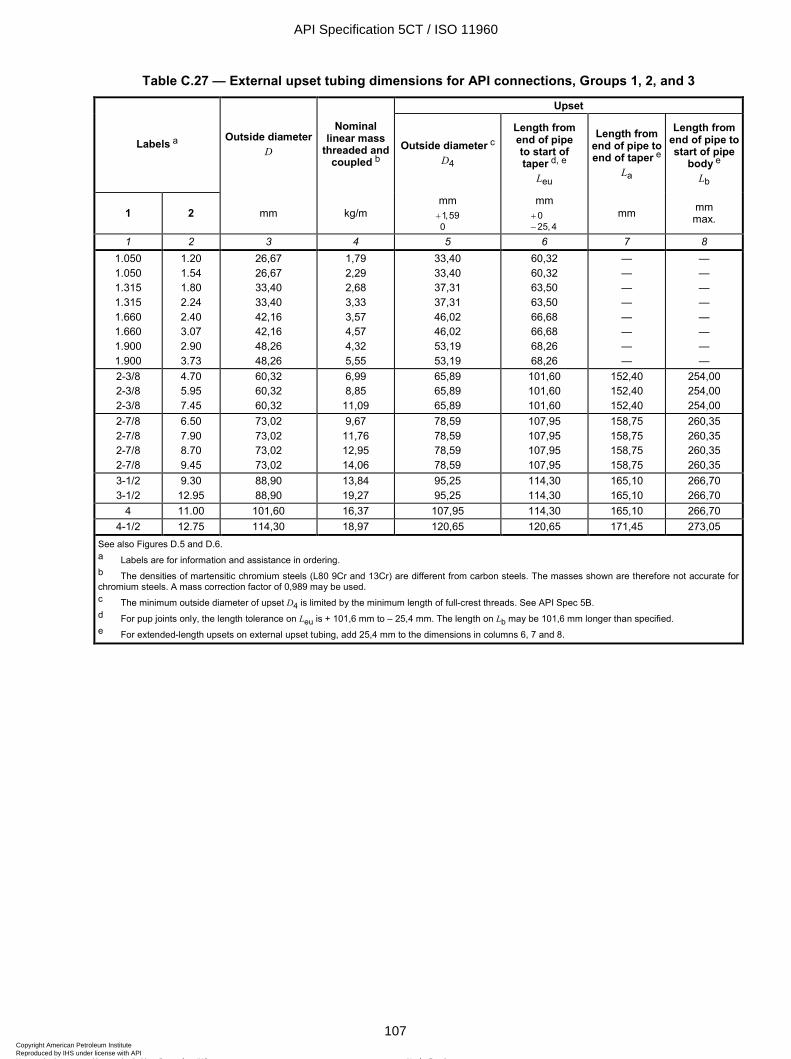
ISO 11960:2004(E)
© ISO 2004 – All rights reserved 107
Table C.27 — External upset tubing dimensions for API connections, Groups 1, 2, and 3
Upset
Labels a Outside diameter D
Nominal linear mass
threaded and coupled b
Outside diameter c
D4
Length from end of pipe to start of taper d, e
Leu
Length from end of pipe to end of taper e
La
Length from end of pipe to start of pipe
body e Lb
1 2 mm kg/m mm 1,590+
mm 025, 4
+−
mm mm max.
1 2 3 4 5 6 7 8 1.050 1.050 1.315 1.315 1.660 1.660 1.900 1.900
1.20 1.54 1.80 2.24 2.40 3.07 2.90 3.73
26,67 26,67 33,40 33,40 42,16 42,16 48,26 48,26
1,79 2,29 2,68 3,33 3,57 4,57 4,32 5,55
33,40 33,40 37,31 37,31 46,02 46,02 53,19 53,19
60,32 60,32 63,50 63,50 66,68 66,68 68,26 68,26
— — — — — — — —
— — — — — — — —
2-3/8 2-3/8 2-3/8
4.70 5.95 7.45
60,32 60,32 60,32
6,99 8,85
11,09
65,89 65,89 65,89
101,60 101,60 101,60
152,40 152,40 152,40
254,00 254,00 254,00
2-7/8 2-7/8 2-7/8 2-7/8
6.50 7.90 8.70 9.45
73,02 73,02 73,02 73,02
9,67 11,76 12,95 14,06
78,59 78,59 78,59 78,59
107,95 107,95 107,95 107,95
158,75 158,75 158,75 158,75
260,35 260,35 260,35 260,35
3-1/2 3-1/2
9.30 12.95
88,90 88,90
13,84 19,27
95,25 95,25
114,30 114,30
165,10 165,10
266,70 266,70
4 11.00 101,60 16,37 107,95 114,30 165,10 266,70 4-1/2 12.75 114,30 18,97 120,65 120,65 171,45 273,05
See also Figures D.5 and D.6. a Labels are for information and assistance in ordering. b The densities of martensitic chromium steels (L80 9Cr and 13Cr) are different from carbon steels. The masses shown are therefore not accurate for chromium steels. A mass correction factor of 0,989 may be used. c The minimum outside diameter of upset D4 is limited by the minimum length of full-crest threads. See API Spec 5B. d For pup joints only, the length tolerance on Leu is + 101,6 mm to – 25,4 mm. The length on Lb may be 101,6 mm longer than specified. e For extended-length upsets on external upset tubing, add 25,4 mm to the dimensions in columns 6, 7 and 8.
API Specification 5CT / ISO 11960
107Copyright American Petroleum Institute Reproduced by IHS under license with API
Not for ResaleNo reproduction or networking permitted without license from IHS
--`,,,```-`-`,,`,,`,`,,`---
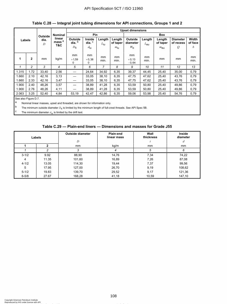
ISO 11960:2004(E)
108 © ISO 2004 – All rights reserved
Table C.28 — Integral joint tubing dimensions for API connections, Groups 1 and 2
Upset dimensions Pin Box
Labels Outside
dia. D
Nominal linear
mass a T&C
Outside dia. b
D4
Inside dia. c
diu
Length Liu
Length of taper
miu
Outside diameter
Wb
LengthLeu
Length of taper
meu
Diameter of recess
Q
Width of face
b
1 2 mm kg/m mm 1,590+
mm 0,380
+ mm min.
mm min.
mm 0,130, 64
+−
mm min. mm mm mm
min.
1 2 3 4 5 6 7 8 9 10 11 12 13 1.315 1.72 33,40 2,56 — 24,64 34,92 6,35 39,37 44,45 25,40 35,00 0,79 1.660 1.660
2.10 2.33
42,16 42,16
3,13 3,47
— —
33,05 33,05
38,10 38,10
6,35 6,35
47,75 47,75
47,62 47,62
25,40 25,40
43,76 43,76
0,79 0,79
1.900 1.900
2.40 2.76
48,26 48,26
3,57 4,11
— —
38,89 38,89
41,28 41,28
6,35 6,35
53,59 53,59
50,80 50,80
25,40 25,40
49,86 49,86
0,79 0,79
2.063 3.25 52,40 4,84 53,19 42,47 42,86 6,35 59,06 53,98 25,40 54,76 0,79 See also Figure D.7. a Nominal linear masses, upset and threaded, are shown for information only. b The minimum outside diameter D4 is limited by the minimum length of full-crest threads. See API Spec 5B. c The minimum diameter d iu is limited by the drift test.
Table C.29 — Plain-end liners — Dimensions and masses for Grade J55
Labels Outside diameter
D
Plain-end linear mass
Wall thickness
t
Inside diameter
d 1 2 mm kg/m mm mm 1 2 3 4 5 6
3-1/2 4
4-1/2 5
5-1/2 6-5/8
9.92 11.35 13.05 17.95 19.83 27.67
88,90 101,60 114,30 127,00 139,70 168,28
14,76 16,89 19,44 26,70 29,52 41,18
7,34 7,26 7,37 9,19 9,17
10,59
74,22 87,08 99,56 108,62 121,36 147,10
API Specification 5CT / ISO 11960
108Copyright American Petroleum Institute Reproduced by IHS under license with API
Not for ResaleNo reproduction or networking permitted without license from IHS
--`,,,```-`-`,,`,,`,`,,`---

ISO 11960:2004(E)
© ISO 2004 – All rights reserved 109
Table C.30 — Range lengths Dimensions in metres
Range 1 Range 2 Range 3 CASING AND LINERS Total range length, inclusive Range length for 95 % or more of carload: a Permissible variation, max. Permissible length, min.
4,88 to 7,62
1,83 5,49
7,62 to 10,36
1,52 8,53
10,36 to 14,63
1,83 10,97
THREADED AND COUPLED TUBING AND CASING USED AS TUBING Total range length, inclusive Range length for 100 % of carload: a Permissible variation, max.
6,10 to 7,32 b
0,61
8,53 to 9,75 c
0,61
11,58 to 12,80 d
0,61 INTEGRAL JOINT TUBING (including IJ/UF and IJ/SF) Total range length, inclusive Range length for 100 % of carload: a Permissible variation, max.
6,10 to 7.92 b
0,61
8,53 to 10,36
0,61
11,58 to 13,72
0,61
PUP JOINTS Lengths 0,61; 0,91; 1,22; 1,83; 2,44; 3,05 and 3,66 e Tolerance ± 0,076
a Carload tolerances shall not apply to order items of less than 18 144 kg of pipe. For any carload of 18 144 kg or more of pipe that is shipped to the final destination without transfer or removal from the car, the tolerance shall apply to each car. For any order item consisting of more than 18 144 kg of pipe that is shipped from the manufacturer's facility by rail, but not to the final destination, the carload tolerance shall apply to the overall quantity of pipe shipped on the order item, but not to the individual carloads. b By agreement between purchaser and manufacturer, the maximum length may be increased to 8,53 m. c By agreement between purchaser and manufacturer, the maximum length may be increased to 10,36 m. d By agreement between purchaser and manufacturer, the maximum length may be increased to 13,72 m. e 0,61 m pup joints may be furnished up to 0,91 m long by agreement between purchaser and manufacturer, and lengths other than those listed may be furnished by agreement between purchaser and manufacturer.
Table C.31 — Standard drift size Dimensions in millimetres
Standard drift mandrel size min. Product and Label 1
Length Diameter Casing a and liners
< 9-5/8 W 9-5/8 to u 13-3/8
> 13-3/8
152 305 305
d – 3,18 d – 3,97 d – 4,76
Tubing b u 2-7/8 > 2-7/8
1 067 1 067
d – 2,38 d – 3,18
a The minimum diameter of the drift mandrel for extreme-line casing shall be as shown in cols. 12 and 13, Table C.26. b Integral-joint tubing shall be tested before upsetting with a drift mandrel as shown, and shall also be drift tested at the pin end, after upsetting, with a cylindrical drift mandrel 1 067 mm in length and d iu – 0,38 mm in diameter (see Table C.28, Col. 6 for d iu).
API Specification 5CT / ISO 11960
109Copyright American Petroleum Institute Reproduced by IHS under license with API
Not for ResaleNo reproduction or networking permitted without license from IHS
--`,,,```-`-`,,`,,`,`,,`---
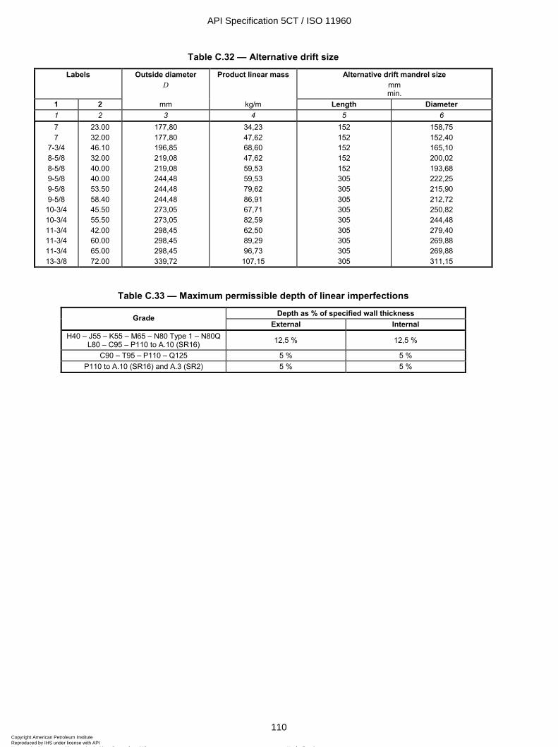
ISO 11960:2004(E)
110 © ISO 2004 – All rights reserved
Table C.32 — Alternative drift size
Labels Outside diameter D
Product linear mass Alternative drift mandrel size mm min.
1 2 mm kg/m Length Diameter 1 2 3 4 5 6 7 7
7-3/4 8-5/8 8-5/8 9-5/8 9-5/8 9-5/8
10-3/4 10-3/4 11-3/4 11-3/4 11-3/4 13-3/8
23.00 32.00 46.10 32.00 40.00 40.00 53.50 58.40 45.50 55.50 42.00 60.00 65.00 72.00
177,80 177,80 196,85 219,08 219,08 244,48 244,48 244,48 273,05 273,05 298,45 298,45 298,45 339,72
34,23 47,62 68,60 47,62 59,53 59,53 79,62 86,91 67,71 82,59 62,50 89,29 96,73 107,15
152 152 152 152 152 305 305 305 305 305 305 305 305 305
158,75 152,40 165,10 200,02 193,68 222,25 215,90 212,72 250,82 244,48 279,40 269,88 269,88 311,15
Table C.33 — Maximum permissible depth of linear imperfections
Depth as % of specified wall thickness Grade External Internal
H40 – J55 – K55 – M65 – N80 Type 1 – N80Q L80 – C95 – P110 to A.10 (SR16) 12,5 % 12,5 %
C90 – T95 – P110 – Q125 5 % 5 % P110 to A.10 (SR16) and A.3 (SR2) 5 % 5 %
API Specification 5CT / ISO 11960
110Copyright American Petroleum Institute Reproduced by IHS under license with API
Not for ResaleNo reproduction or networking permitted without license from IHS
--`,,,```-`-`,,`,,`,`,,`---
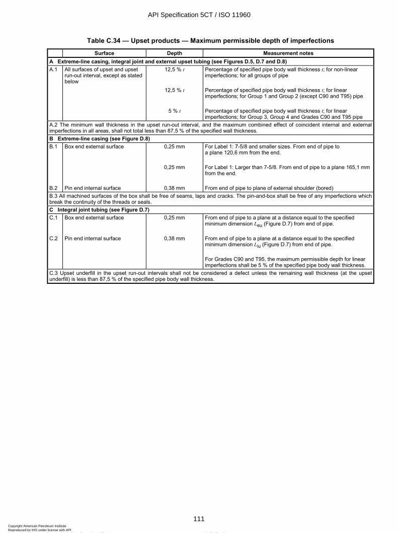
ISO 11960:2004(E)
© ISO 2004 – All rights reserved 111
Table C.34 — Upset products — Maximum permissible depth of imperfections
Surface Depth Measurement notes A Extreme-line casing, integral joint and external upset tubing (see Figures D.5, D.7 and D.8) A.1 All surfaces of upset and upset
run-out interval, except as stated below
12,5 % t
12,5 % t
5 % t
Percentage of specified pipe body wall thickness t; for non-linear imperfections; for all groups of pipe Percentage of specified pipe body wall thickness t; for linear imperfections; for Group 1 and Group 2 (except C90 and T95) pipe Percentage of specified pipe body wall thickness t; for linear imperfections; for Group 3, Group 4 and Grades C90 and T95 pipe
A.2 The minimum wall thickness in the upset run-out interval, and the maximum combined effect of coincident internal and external imperfections in all areas, shall not total less than 87,5 % of the specified wall thickness. B Extreme-line casing (see Figure D.8) B.1 B.2
Box end external surface Pin end internal surface
0,25 mm
0,25 mm
0,38 mm
For Label 1: 7-5/8 and smaller sizes. From end of pipe to a plane 120,6 mm from the end. For Label 1: Larger than 7-5/8. From end of pipe to a plane 165,1 mm from the end. From end of pipe to plane of external shoulder (bored)
B.3 All machined surfaces of the box shall be free of seams, laps and cracks. The pin-and-box shall be free of any imperfections which break the continuity of the threads or seals. C Integral joint tubing (see Figure D.7) C.1 C.2
Box end external surface Pin end internal surface
0,25 mm
0,38 mm
From end of pipe to a plane at a distance equal to the specified minimum dimension Leu (Figure D.7) from end of pipe. From end of pipe to a plane at a distance equal to the specified minimum dimension Liu (Figure D.7) from end of pipe. For Grades C90 and T95, the maximum permissible depth for linear imperfections shall be 5 % of the specified pipe body wall thickness.
C.3 Upset underfill in the upset run-out intervals shall not be considered a defect unless the remaining wall thickness (at the upset underfill) is less than 87,5 % of the specified pipe body wall thickness.
API Specification 5CT / ISO 11960
111Copyright American Petroleum Institute Reproduced by IHS under license with API
Not for ResaleNo reproduction or networking permitted without license from IHS
--`,,,```-`-`,,`,,`,`,,`---
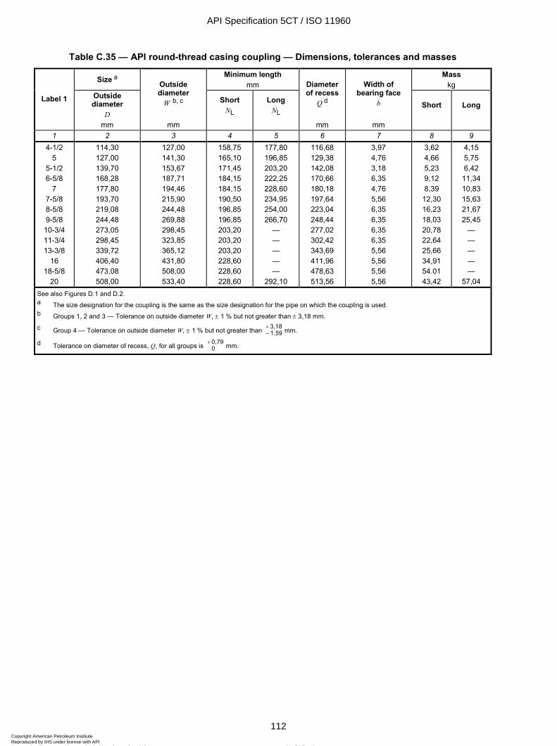
ISO 11960:2004(E)
112 © ISO 2004 – All rights reserved
Table C.35 — API round-thread casing coupling — Dimensions, tolerances and masses
Size a Minimum length mm
Mass kg
Outside diameter
D
Outside diameter
W b, c Short NL
Long NL
Diameter of recess
Q d
Width of bearing face
b Short Long Label 1
mm mm mm mm 1 2 3 4 5 6 7 8 9
4-1/2 5
5-1/2 6-5/8
7 7-5/8 8-5/8 9-5/8
10-3/4 11-3/4 13-3/8
16 18-5/8
20
114,30 127,00 139,70 168,28 177,80 193,70 219,08 244,48 273,05 298,45 339,72 406,40 473,08 508,00
127,00 141,30 153,67 187,71 194,46 215,90 244,48 269,88 298,45 323,85 365,12 431,80 508,00 533,40
158,75 165,10 171,45 184,15 184,15 190,50 196,85 196,85 203,20 203,20 203,20 228,60 228,60 228,60
177,80 196,85 203,20 222,25 228,60 234,95 254,00 266,70
— — — — —
292,10
116,68 129,38 142,08 170,66 180,18 197,64 223,04 248,44 277,02 302,42 343,69 411,96 478,63 513,56
3,97 4,76 3,18 6,35 4,76 5,56 6,35 6,35 6,35 6,35 5,56 5,56 5,56 5,56
3,62 4,66 5,23 9,12 8,39
12,30 16,23 18,03 20,78 22,64 25,66 34,91 54.01 43,42
4,15 5,75 6,42
11,34 10,83 15,63 21,67 25,45
— — — — —
57,04 See also Figures D.1 and D.2. a The size designation for the coupling is the same as the size designation for the pipe on which the coupling is used. b Groups 1, 2 and 3 — Tolerance on outside diameter W, ± 1 % but not greater than ± 3,18 mm.
c Group 4 — Tolerance on outside diameter W, ± 1 % but not greater than 3,181,59
+− mm.
d Tolerance on diameter of recess, Q, for all groups is 0,790
+ mm.
API Specification 5CT / ISO 11960
112Copyright American Petroleum Institute Reproduced by IHS under license with API
Not for ResaleNo reproduction or networking permitted without license from IHS
--`,,,```-`-`,,`,,`,`,,`---

ISO 11960:2004(E)
© ISO 2004 – All rights reserved 113
Table C.36 — API buttress thread casing coupling — Dimensions, tolerances and masses
Size a Outside diameter Mass kg
Outside diameter
D
Regular W b, c
Special clearance d
Wc
Minimum length
NL
Diameter of counterbore
Q
Width of bearing face
b Regular Special clearance
Label 1
mm mm mm mm mm mm 1 2 3 4 5 6 7 8 9
4-1/2 5
5-1/2 6-5/8
7 7-5/8 8-5/8 9-5/8 10-3/4 11-3/4 13-3/8
16 18-5/8
20
114,30 127,00 139,70 168,28 177,80 193,68 219,08 244,48 273,05 298,45 339,72 406,40 473,08 508,00
127,00 141,30 153,67 187,71 194,46 215,90 244,48 269,88 298,45 323,85 365,12 431,80 508,00 533,40
123,82 136,52 149,22 177,80 187,32 206,38 231,78 257,18 285,75
— — — — —
225,42 231,78 234,95 244,48 254,00 263,52 269,88 269,88 269,88 269,88 269,88 269,88 269,88 269,88
117,86 130,56 143,26 171,83 181,36 197,23 222,63 248,03 276,61 302,01 343,28 410,31 476,99 511,91
3,18 3,97 3,97 6,35 5,56 7,94 9,52 9,52 9,52 9,52 9,52 9,52 9,52 9,52
4,55 5,85 6,36 11,01 10,54 15,82 20,86 23,16 25,74 28,03 31,77 40,28 62,68 50,10
3,48 4,00 4,47 5,65 6,28 9,29 10,80 12,02 13,39
— — — — —
See also Figure D.3. a The size designation for the coupling is the same as the size designation for the pipe on which the coupling is used. b Groups 1, 2 and 3 : Tolerance on outside diameter W, ± 1 % but not greater than ± 3,18 mm.
c Group 4 : Tolerance on outside diameter W, ± 1 % but not greater than 3,181,59
+− mm.
d Groups 1, 2 and 3 — Tolerance on outside diameter Wc, 0,790,40
+− mm.
Table C.37 — API non-upset tubing coupling — Dimensions, tolerances and masses
Size a Outside diameter
Outside diameter
Minimum length
Diameter of recess
Width of bearing face
Maximum bearing face diameter, special bevel
D W b NL Q b Bf
Mass Label 1
mm mm mm mm mm mm kg 1 2 3 4 5 6 7 8
1.050
1.315 1.660
1.900 2-3/8 2-7/8
3-1/2
4 4-1/2
26,67 33,40 42,16
48,26 60,32 73,02
88,90 101,60 114,30
33,35 42,16 52,17
55,88 73,02 88,90
107,95 120,65 132,08
80,96 82,55 88,90
95,25
107,95 130,18
142,88 146,05 155,58
28,27 35,00 43,76
49,86 61,93 74,63
90,50
103,20 115,90
1,59 2,38 3,18
1,59 4,76 4,76
4,76 4,76 4,76
30,00 37,80 47,17
52,07 66,68 80,98
98,42
111,12 123,19
0,23 0,38 0,59
0,56 1,28 2,34
3,71 4,35 4,89
See also Figure D.4. a The size designation for the coupling is the same as the size designation for the pipe on which the coupling is used. b Tolerance on outside diameter W, ±1 %.
API Specification 5CT / ISO 11960
113Copyright American Petroleum Institute Reproduced by IHS under license with API
Not for ResaleNo reproduction or networking permitted without license from IHS
--`,,,```-`-`,,`,,`,`,,`---
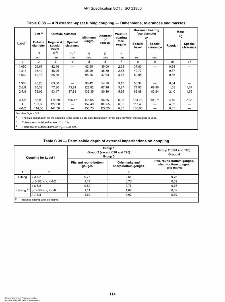
ISO 11960:2004(E)
114 © ISO 2004 – All rights reserved
Table C.38 — API external-upset tubing coupling — Dimensions, tolerances and masses
Size a Outside diameter Maximum bearing
face diameter Bf
Mass kg
Outside diameter
Regular & special bevel
Special clearance
Minimum length
Diameter of
recess
Width of bearing
face, regular Special
bevel Special
clearance Regular Special clearance
D W b Wc c NL Q b
Label 1
mm mm mm mm mm mm mm mm 1 2 3 4 5 6 7 8 9 10 11
1.050 1.315 1.660
1.900 2-3/8 2-7/8
3-1/2
4 4-1/2
26,67 33,40 42,16
48,26 60,32 73,02
88,90
101,60 114,30
42,16 48,26 55,88
63,50 77,80 93,17
114,30 127,00 141,30
— — —
— 73,91 87,88
106,17
— —
82,55 88,90 95,25
98,42
123,82 133,35
146,05 152,40 158,75
35,00 38,89 47,63
54,76 67,46 80,16
96,85
109,55 122,25
2,38 2,38 3,18
3,18 3,97 5,56
6,35 6,35 6,35
37,80 42,77 50,95
58,34 71,83 85,88
104,78 117,48 130,96
— — —
— 69,90 83,24
100,71
— —
0,38 0,57 0,68
0,84 1,55 2,40
4,10 4,82 6,05
— — —
— 1,07 1,55
2,38 — —
See also Figure D.5. a The size designation for the coupling is the same as the size designation for the pipe on which the coupling is used. b Tolerance on outside diameter W, ± 1 %. c Tolerance on outside diameter Wc, ± 0,38 mm.
Table C.39 — Permissible depth of external imperfections on coupling
Group 1 Group 2 (except C90 and T95)
Group 3
Group 2 (C90 and T95) Group 4
Coupling for Label 1 Pits and round-bottom
gouges Grip marks and
sharp-bottom gouges Pits, round-bottom gouges,
sharp-bottom gouges, grip marks
1 2 3 4 5 < 3-1/2 0,76 0,64 0,76 Tubing W 3-1/2 to u 4-1/2 1,14 0,76 0,89
< 6-5/8 0,89 0,76 0,76 Casing a W 6-5/8 to u 7-5/8 1,14 1,02 0,89
> 7-5/8 1,52 1,02 0,89 a Includes casing used as tubing.
API Specification 5CT / ISO 11960
114Copyright American Petroleum Institute Reproduced by IHS under license with API
Not for ResaleNo reproduction or networking permitted without license from IHS
--`,,,```-`-`,,`,,`,`,,`---

ISO 11960:2004(E)
© ISO 2004 – All rights reserved 115
Table C.40 — Frequency of tensile tests — Casing and tubing
Number of tests Group Label 1 Maximum number of pieces in a lot per lot per heat
1 2 3 4 5 < 6-5/8 400 a, b 1 1 1 W 6-5/8 200 a, b 1 1 u 4-1/2 – Grades M65, L80 Type 1, C95 200 a, b 2 c 1 u 4-1/2 – Grades L80 9Cr, L80 13Cr 200 b, d 2 c — u 4-1/2 – Grades C90, T95 200 b, d 1 — > 4-1/2 – Grades M65, L80 Type 1, C95 100 a, b 2 c 1 > 4-1/2 – Grades L80 9Cr, L80 13Cr 100 b, d 2 c —
2
> 4-1/2 – Grades C90, T95 100 b, d 1 — < 6 5/8 200 a, b 1 1 3 W 6 5/8 100 a, b 1 1
4 All sizes — d 3 c — For Groups 1, 2 and 3 multiple-length seamless pipe, a length shall be considered as all of the sections cut from a particular multiple length, provided the pipe receives no additional heat treatment after being cut into individual lengths. NOTE Table includes casing used as tubing. a See 10.2.1. b See 10.4.2. c See 10.4.3. d See 10.2.2.
API Specification 5CT / ISO 11960
115Copyright American Petroleum Institute Reproduced by IHS under license with API
Not for ResaleNo reproduction or networking permitted without license from IHS
--`,,,```-`-`,,`,,`,`,,`---

ISO 11960:2004(E)
116 © ISO 2004 – All rights reserved
Table C.41 — Frequency of tensile tests — Coupling stock and couplings
Source of coupling Number of tests Group Material Condition when heat-
treated
Maximum number of pieces in a lot per lot per heat
1 2 3 4 5 6 Coupling stock for pipe u Label 1: 4-1/2
200 a 1 1 b
Coupling stock for pipe > Label 1: 4-1/2
100 a 1 1 b
Coupling stock
Coupling blank 400 c 1 —
Groups 1 & 3
Hot forging Coupling blank 400 c 1 — Coupling stock for pipe u Label 1: 4-1/2
200 a 2 d 2 d
Coupling stock for pipe > Label 1: 4-1/2
100 a 2 d 2 d
Coupling stock
Coupling blank 400 c 2 —
Group 2 Grades L80 Type 1
and C95
Hot forging Coupling blank 400 c 2 — Coupling stock for pipe u Label 1: 4-1/2
200 d 2 d —
Coupling stock for pipe > Label 1: 4-1/2
100 d 2 d —
Coupling stock
Coupling blank 400 c 2 —
Group 2 Grades L80 9Cr and
L80 13Cr
Hot forging Coupling blank 400 c 2 — Coupling stock for pipe Label 1: All sizes
1 b 1 — Coupling stock
Coupling blank Label 1: < 9-5/8: 50 c
Label 1: W 9-5/8: 30 c 1 — Group 2
Grades C90 and T95
Hot forging Coupling blank Label 1: < 9-5/8: 50 c
Label 1: W 9-5/8: 30 c 1 —
Coupling stock for pipe Label 1: All sizes
1 b 1 — Group 4
Coupling stock Coupling blank
Label 1: < 9-5/8: 50 c
Label 1: W 9-5/8: 30 c 1 —
a See 10.2.1. b Approximately 50 % from each end. c See 10.2.3. d See 10.2.2.
API Specification 5CT / ISO 11960
116Copyright American Petroleum Institute Reproduced by IHS under license with API
Not for ResaleNo reproduction or networking permitted without license from IHS
--`,,,```-`-`,,`,,`,`,,`---
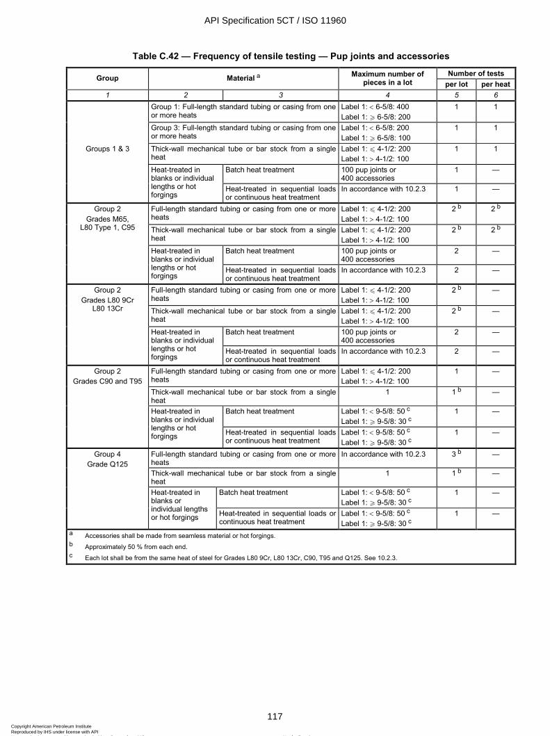
ISO 11960:2004(E)
© ISO 2004 – All rights reserved 117
Table C.42 — Frequency of tensile testing — Pup joints and accessories
Number of tests Group Material a Maximum number of pieces in a lot per lot per heat
1 2 3 4 5 6 Group 1: Full-length standard tubing or casing from one
or more heats Label 1: < 6-5/8: 400 Label 1: W 6-5/8: 200
1 1
Group 3: Full-length standard tubing or casing from one or more heats
Label 1: < 6-5/8: 200 Label 1: W 6-5/8: 100
1 1
Groups 1 & 3 Thick-wall mechanical tube or bar stock from a single heat
Label 1: u 4-1/2: 200 Label 1: > 4-1/2: 100
1 1
Batch heat treatment 100 pup joints or 400 accessories
1 —
Heat-treated in blanks or individual lengths or hot forgings
Heat-treated in sequential loads or continuous heat treatment
In accordance with 10.2.3 1 —
Full-length standard tubing or casing from one or more heats
Label 1: u 4-1/2: 200 Label 1: > 4-1/2: 100
2 b 2 b
Thick-wall mechanical tube or bar stock from a single heat
Label 1: u 4-1/2: 200 Label 1: > 4-1/2: 100
2 b 2 b
Batch heat treatment 100 pup joints or 400 accessories
2 —
Group 2 Grades M65,
L80 Type 1, C95
Heat-treated in blanks or individual lengths or hot forgings
Heat-treated in sequential loads or continuous heat treatment
In accordance with 10.2.3 2 —
Full-length standard tubing or casing from one or more heats
Label 1: u 4-1/2: 200 Label 1: > 4-1/2: 100
2 b —
Thick-wall mechanical tube or bar stock from a single heat
Label 1: u 4-1/2: 200 Label 1: > 4-1/2: 100
2 b —
Batch heat treatment 100 pup joints or 400 accessories
2 —
Group 2 Grades L80 9Cr
L80 13Cr
Heat-treated in blanks or individual lengths or hot forgings
Heat-treated in sequential loads or continuous heat treatment
In accordance with 10.2.3 2 —
Full-length standard tubing or casing from one or more heats
Label 1: u 4-1/2: 200 Label 1: > 4-1/2: 100
1 —
Thick-wall mechanical tube or bar stock from a single heat
1 1 b —
Batch heat treatment Label 1: < 9-5/8: 50 c Label 1: W 9-5/8: 30 c
1 —
Group 2 Grades C90 and T95
Heat-treated in blanks or individual lengths or hot forgings Heat-treated in sequential loads
or continuous heat treatment Label 1: < 9-5/8: 50 c Label 1: W 9-5/8: 30 c
1 —
Full-length standard tubing or casing from one or more heats
In accordance with 10.2.3 3 b —
Thick-wall mechanical tube or bar stock from a single heat
1 1 b —
Batch heat treatment Label 1: < 9-5/8: 50 c Label 1: W 9-5/8: 30 c
1 —
Group 4 Grade Q125
Heat-treated in blanks or individual lengths or hot forgings Heat-treated in sequential loads or
continuous heat treatment Label 1: < 9-5/8: 50 c Label 1: W 9-5/8: 30 c
1 —
a Accessories shall be made from seamless material or hot forgings. b Approximately 50 % from each end. c Each lot shall be from the same heat of steel for Grades L80 9Cr, L80 13Cr, C90, T95 and Q125. See 10.2.3.
API Specification 5CT / ISO 11960
117Copyright American Petroleum Institute Reproduced by IHS under license with API
Not for ResaleNo reproduction or networking permitted without license from IHS
--`,,,```-`-`,,`,,`,`,,`---

ISO 11960:2004(E)
118 © ISO 2004 – All rights reserved
Table C.43 — Frequency of hardness testing
Grade Product Number of tests per lot
Maximum number of pieces in a lot Type of test Location
1 2 3 4 5 6 Label 1: u 4-1/2 2 a 200 b, c Through-wall,
1 quadrant Pipe, tube or stock body tensile test Pipe, coupling stock,
thick-wall mechanical tubes, bar stock Label 1: > 4-1/2 2 a 100 b, c Through-wall,
1 quadrant Pipe, tube or stock body tensile test
Coupling blanks or hot forgings 2 a Heat-treat lot or 400 couplings b, c
Through-wall, 1 quadrant
Coupling blank tensile test
Batch heat treatment (method a, 10.2.3)
2 a 100 pup joints or 400 accessories b, c
Through-wall, 1 quadrant
Pup joint or accessory tensile
test Heat-treated in sequential loads (method b, 10.2.3)
2 a Lot (see 10.2) b, c Through-wall, 1 quadrant
Pup joint or accessory tensile
test
Grades M65, L80
Pup joints and accessories (heat-treated in blank or individual lengths)
Continuous heat treatment (method c, 10.2.3)
2 a Lot (see 10.2) b, c Through-wall, 1 quadrant
Pup joint or accessory tensile
test As-quenched product 1 Each production run or
heat treatment practice Through-wall, 4 quadrants
Design area of greatest thickness
Non-upset pipe 1 Each length Through-wall, 1 quadrant
Approx. 50 % from each end
1 Each length Surface – HRC or HBW
Pipe body and one upset d
Upset pipe 1 20 c Through-wall, 4 quadrants
One upset
1 Label 1: u 4-1/2: 200 Label 1: > 4-1/2: 100
Through-wall, 4 quadrants
Pipe body tensile test
Tube-length heat treatment
2 Each length Through-wall, 4 quadrants
One from each end
1 Each piece Surface – HRC or HBW
Each piece
Grades C90, T95
Couplings, pup joints and accessories
Individual heat treatment
1 Label 1: < 9-5/8: 50 c Label 1: W 9-5/8: 30 c
Through-wall, 4 quadrants
From a piece with the highest surface hardness number
in the lot Casing 3 Lot (see 10.2) b, c Through-wall,
1 quadrant Pipe body
Tube-length heat treatment
1 Each length Through-wall, 1 quadrant
Approx. 50 % from each end
1 Each piece Surface – HRC or HBW
Each piece Grade Q125
Couplings, pup joints and accessories
Individual heat treatment
1 Label 1: < 9-5/8: 50 c Label 1: W 9-5/8: 30 c
Through-wall, 1 quadrant
Randomly selected piece
a Lots which include more than one heat shall have two hardness tests from each heat. b The lengths tested shall be selected randomly and represent the start and end of the heat treatment cycle. c Each lot shall be from the same heat of steel for Grades L80 9Cr, L80 13Cr, C90, T95 and Q125. d One upset approximately 50 % from each end if both ends are upset.
API Specification 5CT / ISO 11960
118Copyright American Petroleum Institute Reproduced by IHS under license with API
Not for ResaleNo reproduction or networking permitted without license from IHS
--`,,,```-`-`,,`,,`,`,,`---
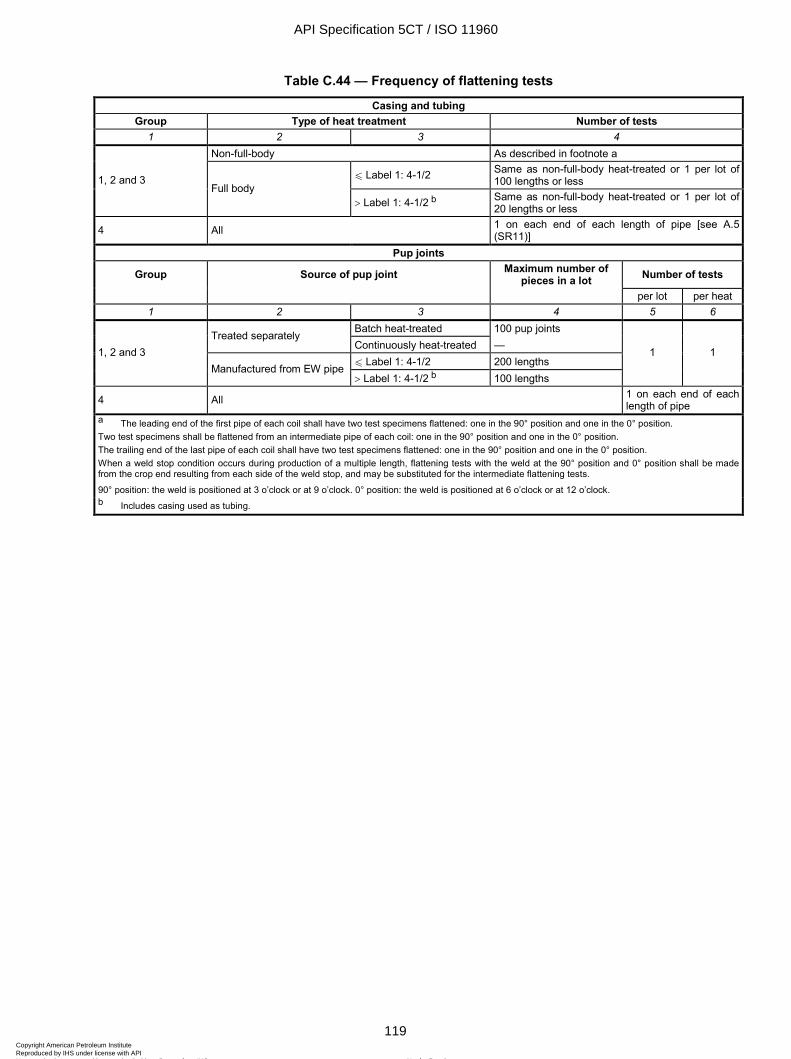
ISO 11960:2004(E)
© ISO 2004 – All rights reserved 119
Table C.44 — Frequency of flattening tests
Casing and tubing Group Type of heat treatment Number of tests
1 2 3 4 Non-full-body As described in footnote a
u Label 1: 4-1/2 Same as non-full-body heat-treated or 1 per lot of 100 lengths or less 1, 2 and 3
Full body > Label 1: 4-1/2 b Same as non-full-body heat-treated or 1 per lot of
20 lengths or less
4 All 1 on each end of each length of pipe [see A.5 (SR11)]
Pup joints
Group Source of pup joint Maximum number of pieces in a lot Number of tests
per lot per heat 1 2 3 4 5 6
Batch heat-treated 100 pup joints Treated separately Continuously heat-treated — u Label 1: 4-1/2 200 lengths
1, 2 and 3 Manufactured from EW pipe
> Label 1: 4-1/2 b 100 lengths
1 1
4 All 1 on each end of each length of pipe
a The leading end of the first pipe of each coil shall have two test specimens flattened: one in the 90° position and one in the 0° position. Two test specimens shall be flattened from an intermediate pipe of each coil: one in the 90° position and one in the 0° position. The trailing end of the last pipe of each coil shall have two test specimens flattened: one in the 90° position and one in the 0° position. When a weld stop condition occurs during production of a multiple length, flattening tests with the weld at the 90° position and 0° position shall be made from the crop end resulting from each side of the weld stop, and may be substituted for the intermediate flattening tests.
90° position: the weld is positioned at 3 o’clock or at 9 o’clock. 0° position: the weld is positioned at 6 o’clock or at 12 o’clock. b Includes casing used as tubing.
API Specification 5CT / ISO 11960
119Copyright American Petroleum Institute Reproduced by IHS under license with API
Not for ResaleNo reproduction or networking permitted without license from IHS
--`,,,```-`-`,,`,,`,`,,`---
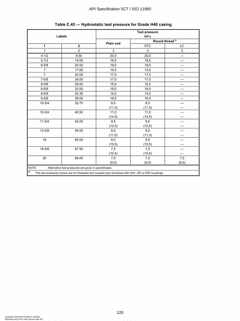
ISO 11960:2004(E)
120 © ISO 2004 – All rights reserved
Table C.45 — Hydrostatic test pressure for Grade H40 casing
Test pressure MPa Labels
Round thread a 1 2
Plain end STC LC
1 2 3 4 5 4-1/2 9.50 20,0 20,0 — 5-1/2 14.00 19,5 19,5 — 6-5/8 20.00 19,0 19,0 —
7 17.00 14,5 14,5 — 7 20.00 17,0 17,0 —
7-5/8 24.00 17,5 17,5 — 8-5/8 28.00 15,5 15,5 — 8-5/8 32.00 18,0 18,0 — 9-5/8 32.30 14,5 14,5 — 9-5/8 36.00 16,0 16,0 — 10-3/4 32.75 8,5
(11,5) 8,5
(11,5) — —
10-3/4 40.50 11,0 (14,5)
11,0 (14,5)
— —
11-3/4 42.00 9,5 (12,5)
9,5 (12,5)
— —
13-3/8 48.00 8,0 (11,0)
8,0 (11,0)
— —
16 65.00 8,0 (10,5)
8,0 (10,5)
— —
18-5/8 87.50 7,5 (10,5)
7,5 (10,5)
— —
20 94.00 7,5 (9,5)
7,5 (9,5)
7,5 (9,5)
NOTE Alternative test pressures are given in parentheses. a The test pressures shown are for threaded and coupled pipe furnished with H40, J55 or K55 couplings.
API Specification 5CT / ISO 11960
120Copyright American Petroleum Institute Reproduced by IHS under license with API
Not for ResaleNo reproduction or networking permitted without license from IHS
--`,,,```-`-`,,`,,`,`,,`---
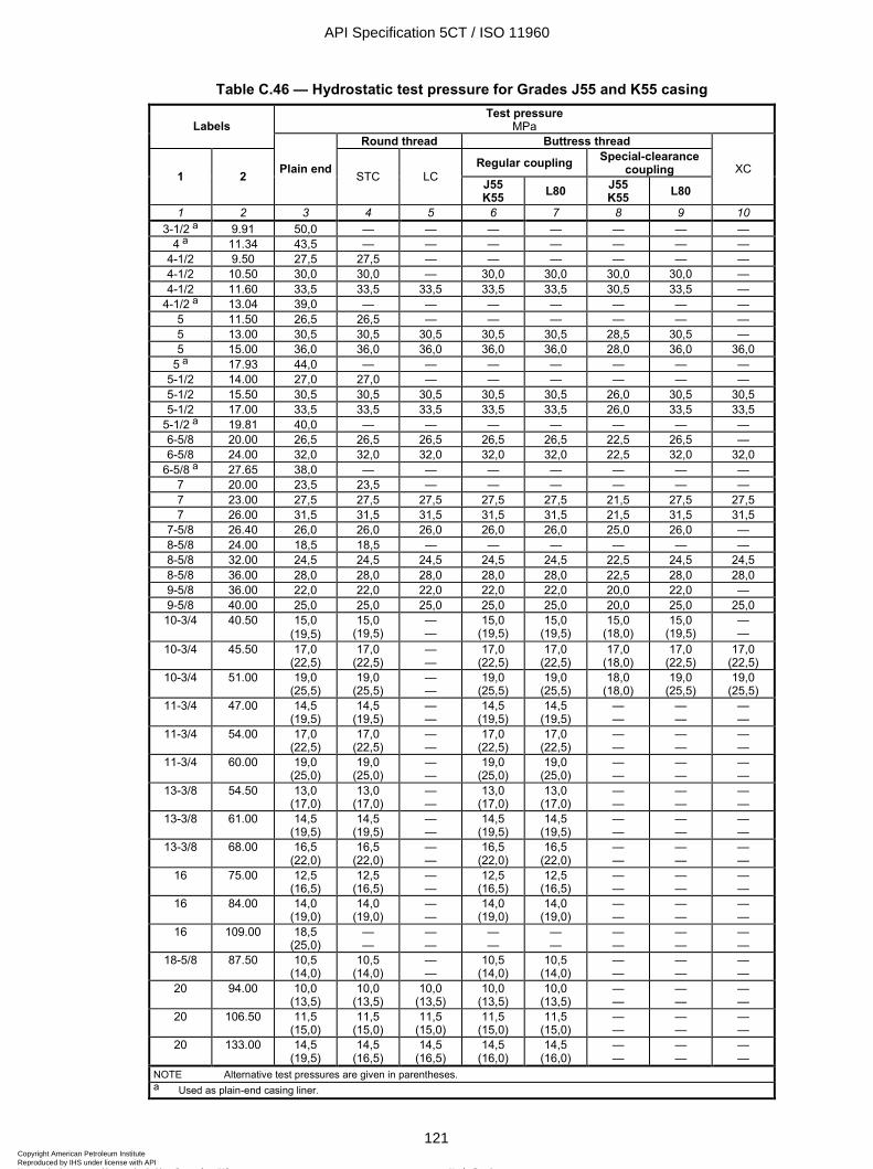
ISO 11960:2004(E)
© ISO 2004 – All rights reserved 121
Table C.46 — Hydrostatic test pressure for Grades J55 and K55 casing Test pressure
MPa Labels Round thread Buttress thread
Regular coupling Special-clearance coupling 1 2 Plain end STC LC J55
K55 L80 J55 K55 L80
XC
1 2 3 4 5 6 7 8 9 10 3-1/2 a 9.91 50,0 — — — — — — —
4 a 11.34 43,5 — — — — — — — 4-1/2 9.50 27,5 27,5 — — — — — — 4-1/2 10.50 30,0 30,0 — 30,0 30,0 30,0 30,0 — 4-1/2 11.60 33,5 33,5 33,5 33,5 33,5 30,5 33,5 —
4-1/2 a 13.04 39,0 — — — — — — — 5 11.50 26,5 26,5 — — — — — — 5 13.00 30,5 30,5 30,5 30,5 30,5 28,5 30,5 — 5 15.00 36,0 36,0 36,0 36,0 36,0 28,0 36,0 36,0
5 a 17.93 44,0 — — — — — — — 5-1/2 14.00 27,0 27,0 — — — — — — 5-1/2 15.50 30,5 30,5 30,5 30,5 30,5 26,0 30,5 30,5 5-1/2 17.00 33,5 33,5 33,5 33,5 33,5 26,0 33,5 33,5
5-1/2 a 19.81 40,0 — — — — — — — 6-5/8 20.00 26,5 26,5 26,5 26,5 26,5 22,5 26,5 — 6-5/8 24.00 32,0 32,0 32,0 32,0 32,0 22,5 32,0 32,0
6-5/8 a 27.65 38,0 — — — — — — — 7 20.00 23,5 23,5 — — — — — — 7 23.00 27,5 27,5 27,5 27,5 27,5 21,5 27,5 27,5 7 26.00 31,5 31,5 31,5 31,5 31,5 21,5 31,5 31,5
7-5/8 26.40 26,0 26,0 26,0 26,0 26,0 25,0 26,0 — 8-5/8 24.00 18,5 18,5 — — — — — — 8-5/8 32.00 24,5 24,5 24,5 24,5 24,5 22,5 24,5 24,5 8-5/8 36.00 28,0 28,0 28,0 28,0 28,0 22,5 28,0 28,0 9-5/8 36.00 22,0 22,0 22,0 22,0 22,0 20,0 22,0 — 9-5/8 40.00 25,0 25,0 25,0 25,0 25,0 20,0 25,0 25,0 10-3/4 40.50 15,0
(19,5) 15,0
(19,5) — —
15,0 (19,5)
15,0 (19,5)
15,0 (18,0)
15,0 (19,5)
— —
10-3/4 45.50 17,0 (22,5)
17,0 (22,5)
— —
17,0 (22,5)
17,0 (22,5)
17,0 (18,0)
17,0 (22,5)
17,0 (22,5)
10-3/4 51.00 19,0 (25,5)
19,0 (25,5)
— —
19,0 (25,5)
19,0 (25,5)
18,0 (18,0)
19,0 (25,5)
19,0 (25,5)
11-3/4 47.00 14,5 (19,5)
14,5 (19,5)
— —
14,5 (19,5)
14,5 (19,5)
— —
— —
— —
11-3/4 54.00 17,0 (22,5)
17,0 (22,5)
— —
17,0 (22,5)
17,0 (22,5)
— —
— —
— —
11-3/4 60.00 19,0 (25,0)
19,0 (25,0)
— —
19,0 (25,0)
19,0 (25,0)
— —
— —
— —
13-3/8 54.50 13,0 (17,0)
13,0 (17,0)
— —
13,0 (17,0)
13,0 (17,0)
— —
— —
— —
13-3/8 61.00 14,5 (19,5)
14,5 (19,5)
— —
14,5 (19,5)
14,5 (19,5)
— —
— —
— —
13-3/8 68.00 16,5 (22,0)
16,5 (22,0)
— —
16,5 (22,0)
16,5 (22,0)
— —
— —
— —
16 75.00 12,5 (16,5)
12,5 (16,5)
— —
12,5 (16,5)
12,5 (16,5)
— —
— —
— —
16 84.00 14,0 (19,0)
14,0 (19,0)
— —
14,0 (19,0)
14,0 (19,0)
— —
— —
— —
16 109.00 18,5 (25,0)
— —
— —
— —
— —
— —
— —
— —
18-5/8 87.50 10,5 (14,0)
10,5 (14,0)
— —
10,5 (14,0)
10,5 (14,0)
— —
— —
— —
20 94.00 10,0 (13,5)
10,0 (13,5)
10,0 (13,5)
10,0 (13,5)
10,0 (13,5)
— —
— —
— —
20 106.50 11,5 (15,0)
11,5 (15,0)
11,5 (15,0)
11,5 (15,0)
11,5 (15,0)
— —
— —
— —
20 133.00 14,5 (19,5)
14,5 (16,5)
14,5 (16,5)
14,5 (16,0)
14,5 (16,0)
— —
— —
— —
NOTE Alternative test pressures are given in parentheses. a Used as plain-end casing liner.
API Specification 5CT / ISO 11960
121Copyright American Petroleum Institute Reproduced by IHS under license with API
Not for ResaleNo reproduction or networking permitted without license from IHS
--`,,,```-`-`,,`,,`,`,,`---
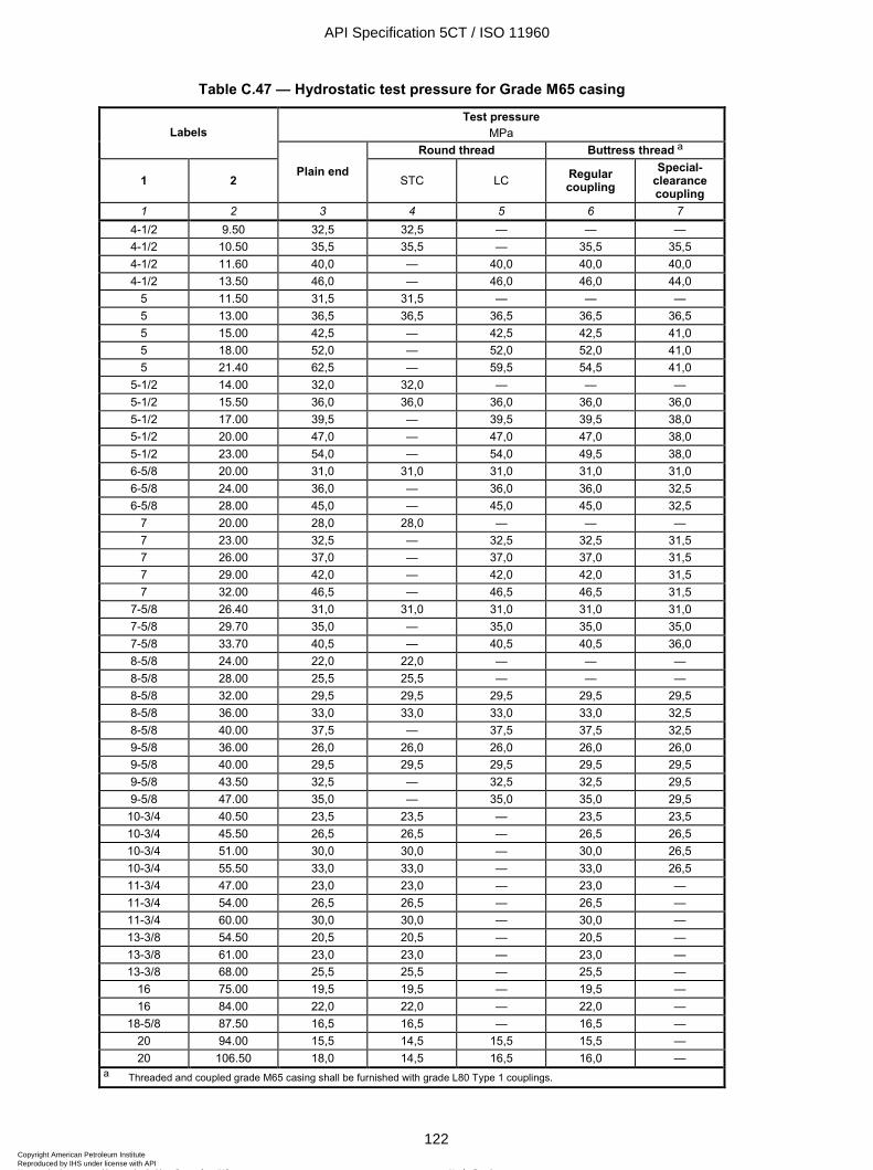
ISO 11960:2004(E)
122 © ISO 2004 – All rights reserved
Table C.47 — Hydrostatic test pressure for Grade M65 casing
Test pressure MPa Labels
Round thread Buttress thread a
1 2 Plain end
STC LC Regular coupling
Special-clearance coupling
1 2 3 4 5 6 7 4-1/2 9.50 32,5 32,5 — — — 4-1/2 10.50 35,5 35,5 — 35,5 35,5 4-1/2 11.60 40,0 — 40,0 40,0 40,0 4-1/2 13.50 46,0 — 46,0 46,0 44,0
5 11.50 31,5 31,5 — — — 5 13.00 36,5 36,5 36,5 36,5 36,5 5 15.00 42,5 — 42,5 42,5 41,0 5 18.00 52,0 — 52,0 52,0 41,0 5 21.40 62,5 — 59,5 54,5 41,0
5-1/2 14.00 32,0 32,0 — — — 5-1/2 15.50 36,0 36,0 36,0 36,0 36,0 5-1/2 17.00 39,5 — 39,5 39,5 38,0 5-1/2 20.00 47,0 — 47,0 47,0 38,0 5-1/2 23.00 54,0 — 54,0 49,5 38,0 6-5/8 20.00 31,0 31,0 31,0 31,0 31,0 6-5/8 24.00 36,0 — 36,0 36,0 32,5 6-5/8 28.00 45,0 — 45,0 45,0 32,5
7 20.00 28,0 28,0 — — — 7 23.00 32,5 — 32,5 32,5 31,5 7 26.00 37,0 — 37,0 37,0 31,5 7 29.00 42,0 — 42,0 42,0 31,5 7 32.00 46,5 — 46,5 46,5 31,5
7-5/8 26.40 31,0 31,0 31,0 31,0 31,0 7-5/8 29.70 35,0 — 35,0 35,0 35,0 7-5/8 33.70 40,5 — 40,5 40,5 36,0 8-5/8 24.00 22,0 22,0 — — — 8-5/8 28.00 25,5 25,5 — — — 8-5/8 32.00 29,5 29,5 29,5 29,5 29,5 8-5/8 36.00 33,0 33,0 33,0 33,0 32,5 8-5/8 40.00 37,5 — 37,5 37,5 32,5 9-5/8 36.00 26,0 26,0 26,0 26,0 26,0 9-5/8 40.00 29,5 29,5 29,5 29,5 29,5 9-5/8 43.50 32,5 — 32,5 32,5 29,5 9-5/8 47.00 35,0 — 35,0 35,0 29,5
10-3/4 40.50 23,5 23,5 — 23,5 23,5 10-3/4 45.50 26,5 26,5 — 26,5 26,5 10-3/4 51.00 30,0 30,0 — 30,0 26,5 10-3/4 55.50 33,0 33,0 — 33,0 26,5 11-3/4 47.00 23,0 23,0 — 23,0 — 11-3/4 54.00 26,5 26,5 — 26,5 — 11-3/4 60.00 30,0 30,0 — 30,0 — 13-3/8 54.50 20,5 20,5 — 20,5 — 13-3/8 61.00 23,0 23,0 — 23,0 — 13-3/8 68.00 25,5 25,5 — 25,5 —
16 75.00 19,5 19,5 — 19,5 — 16 84.00 22,0 22,0 — 22,0 —
18-5/8 87.50 16,5 16,5 — 16,5 — 20 94.00 15,5 14,5 15,5 15,5 — 20 106.50 18,0 14,5 16,5 16,0 —
a Threaded and coupled grade M65 casing shall be furnished with grade L80 Type 1 couplings.
API Specification 5CT / ISO 11960
122Copyright American Petroleum Institute Reproduced by IHS under license with API
Not for ResaleNo reproduction or networking permitted without license from IHS
--`,,,```-`-`,,`,,`,`,,`---

ISO 11960:2004(E)
© ISO 2004 – All rights reserved 123
Table C.48 — Hydrostatic test pressure for Grade L80 casing
Test pressure MPa Labels
Round thread Buttress thread
1 2 Plain end
STC LC Regular coupling
Special-clearance coupling
XC
1 2 3 4 5 6 7 8 4-1/2 11.60 49,0 — 49,0 49,0 44,0 — 4-1/2 13.50 57,0 — 57,0 54,0 44,0 —
5 15.00 52,5 — 52,5 52,5 41,0 52,5 5 18.00 64,0 — 59,5 54,5 41,0 64,0 5 21.40 69,0 — 59,5 54,5 41,0 — 5 23.20 69,0 — 59,5 54,5 41,0 — 5 24.10 69,0 — 59,5 54,5 41,0 —
5-1/2 17.00 49,0 — 49,0 49,0 38,0 49,0 5-1/2 20.00 58,0 — 54,5 49,5 38,0 58,0 5-1/2 23.00 66,5 — 54,5 49,5 38,0 66,5 6-5/8 24.00 47,0 — 47,0 47,0 32,5 47,0 6-5/8 28.00 55,5 — 55,5 54,0 32,5 55,5 6-5/8 32.00 63,5 — 59,0 54,0 32,5 63,5
7 23.00 40,0 — 40,0 40,0 31,5 40,0 7 26.00 45,5 — 45,5 45,5 31,5 45,5 7 29.00 51,5 — 51,0 46,5 31,5 51,5 7 32.00 57,0 — 51,0 46,5 31,5 57,0 7 35.00 63,0 — 51,0 46,5 31,5 63,0 7 38.00 68,0 — 51,0 46,5 31,5 68,0
7-5/8 26.40 38,0 — 38,0 38,0 36,0 38,0 7-5/8 29.70 43,5 — 43,5 43,5 36,0 43,5 7-5/8 33.70 50,0 — 50,0 50,0 36,0 50,0 7-5/8 39.00 58,0 — 58,0 54,0 36,0 58,0 7-5/8 42.80 65,0 — 58,0 54,0 36,0 — 7-5/8 45.30 69,0 — 58,0 54,0 36,0 — 7-5/8 47.10 69,0 — 58,0 54,0 36,0 — 7-3/4 46.10 68,0 — — — — — 8-5/8 36.00 41,0 — 41,0 41,0 32,5 41,0 8-5/8 40.00 46,0 — 46,0 46,0 32,5 46,0 8-5/8 44.00 51,0 — 51,0 51,0 32,5 51,0 8-5/8 49.00 57,0 — 57,0 54,0 32,5 57,0 9-5/8 40.00 36,0 — 36,0 36,0 29,5 36,0 9-5/8 43.50 40,0 — 40,0 40,0 29,5 40,0 9-5/8 47.00 43,5 — 43,5 43,5 29,5 43,5 9-5/8 53.50 50,0 — 50,0 49,0 29,5 50,0 9-5/8 58.40 54,5 — 53,0 49,0 29,5 —
10-3/4 51.00 37,0 37,0 — 37,0 26,5 37,0 10-3/4 55.50 40,5 40,5 — 40,5 26,5 40,5 11-3/4 60.00 37,0 37,0 — 37,0 — — 11-3/4 65.00 40,0 — — — — — 11-3/4 71.00 43,5 — — — — — 13-3/8 68.00 31,5 31,5 — 31,5 — — 13-3/8 72.00 34,0 31,5 — 34,0 — —
16 109.00 36,0 — — — — —
API Specification 5CT / ISO 11960
123Copyright American Petroleum Institute Reproduced by IHS under license with API
Not for ResaleNo reproduction or networking permitted without license from IHS
--`,,,```-`-`,,`,,`,`,,`---
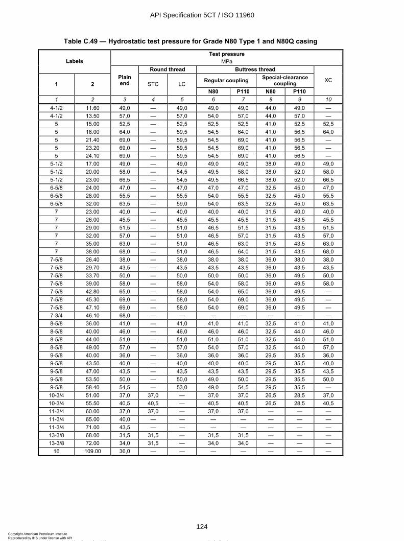
ISO 11960:2004(E)
124 © ISO 2004 – All rights reserved
Table C.49 — Hydrostatic test pressure for Grade N80 Type 1 and N80Q casing
Test pressure MPa Labels
Round thread Buttress thread
Regular coupling Special-clearance coupling 1 2
Plain end STC LC
N80 P110 N80 P110
XC
1 2 3 4 5 6 7 8 9 10 4-1/2 11.60 49,0 — 49,0 49,0 49,0 44,0 49,0 — 4-1/2 13.50 57,0 — 57,0 54,0 57,0 44,0 57,0 —
5 15.00 52,5 — 52,5 52,5 52,5 41,0 52,5 52,5 5 18.00 64,0 — 59,5 54,5 64,0 41,0 56,5 64,0 5 21.40 69,0 — 59,5 54,5 69,0 41,0 56,5 — 5 23.20 69,0 — 59,5 54,5 69,0 41,0 56,5 — 5 24.10 69,0 — 59,5 54,5 69,0 41,0 56,5 —
5-1/2 17.00 49,0 — 49,0 49,0 49,0 38,0 49,0 49,0 5-1/2 20.00 58,0 — 54,5 49,5 58,0 38,0 52,0 58,0 5-1/2 23.00 66,5 — 54,5 49,5 66,5 38,0 52,0 66,5 6-5/8 24.00 47,0 — 47,0 47,0 47,0 32,5 45,0 47,0 6-5/8 28.00 55,5 — 55,5 54,0 55,5 32,5 45,0 55,5 6-5/8 32.00 63,5 — 59,0 54,0 63,5 32,5 45,0 63,5
7 23.00 40,0 — 40,0 40,0 40,0 31,5 40,0 40,0 7 26.00 45,5 — 45,5 45,5 45,5 31,5 43,5 45,5 7 29.00 51,5 — 51,0 46,5 51,5 31,5 43,5 51,5 7 32.00 57,0 — 51,0 46,5 57,0 31,5 43,5 57,0 7 35.00 63,0 — 51,0 46,5 63,0 31,5 43,5 63,0 7 38.00 68,0 — 51,0 46,5 64,0 31,5 43,5 68,0
7-5/8 26.40 38,0 — 38,0 38,0 38,0 36,0 38,0 38,0 7-5/8 29.70 43,5 — 43,5 43,5 43,5 36,0 43,5 43,5 7-5/8 33.70 50,0 — 50,0 50,0 50,0 36,0 49,5 50,0 7-5/8 39.00 58,0 — 58,0 54,0 58,0 36,0 49,5 58,0 7-5/8 42.80 65,0 — 58,0 54,0 65,0 36,0 49,5 — 7-5/8 45.30 69,0 — 58,0 54,0 69,0 36,0 49,5 — 7-5/8 47.10 69,0 — 58,0 54,0 69,0 36,0 49,5 — 7-3/4 46.10 68,0 — — — — — — — 8-5/8 36.00 41,0 — 41,0 41,0 41,0 32,5 41,0 41,0 8-5/8 40.00 46,0 — 46,0 46,0 46,0 32,5 44,0 46,0 8-5/8 44.00 51,0 — 51,0 51,0 51,0 32,5 44,0 51,0 8-5/8 49.00 57,0 — 57,0 54,0 57,0 32,5 44,0 57,0 9-5/8 40.00 36,0 — 36,0 36,0 36,0 29,5 35,5 36,0 9-5/8 43.50 40,0 — 40,0 40,0 40,0 29,5 35,5 40,0 9-5/8 47.00 43,5 — 43,5 43,5 43,5 29,5 35,5 43,5 9-5/8 53.50 50,0 — 50,0 49,0 50,0 29,5 35,5 50,0 9-5/8 58.40 54,5 — 53,0 49,0 54,5 29,5 35,5 —
10-3/4 51.00 37,0 37,0 — 37,0 37,0 26,5 28,5 37,0 10-3/4 55.50 40,5 40,5 — 40,5 40,5 26,5 28,5 40,5 11-3/4 60.00 37,0 37,0 — 37,0 37,0 — — — 11-3/4 65.00 40,0 — — — — — — — 11-3/4 71.00 43,5 — — — — — — — 13-3/8 68.00 31,5 31,5 — 31,5 31,5 — — — 13-3/8 72.00 34,0 31,5 — 34,0 34,0 — — —
16 109.00 36,0 — — — — — — —
API Specification 5CT / ISO 11960
124Copyright American Petroleum Institute Reproduced by IHS under license with API
Not for ResaleNo reproduction or networking permitted without license from IHS
--`,,,```-`-`,,`,,`,`,,`---
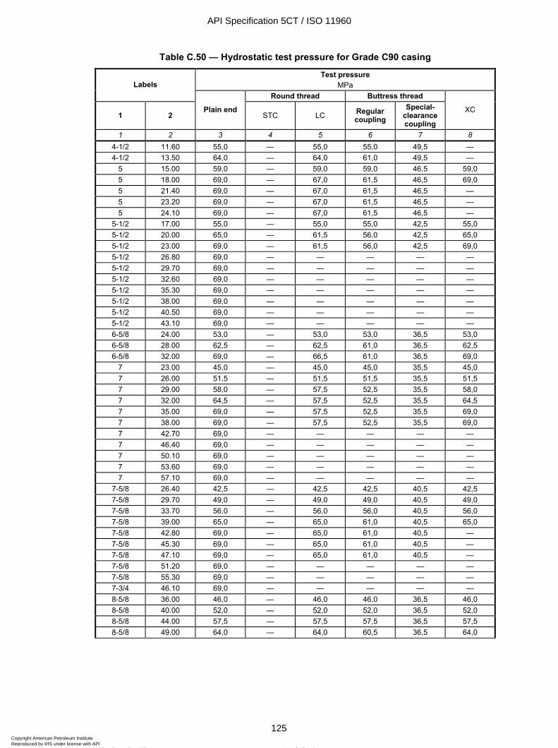
ISO 11960:2004(E)
© ISO 2004 – All rights reserved 125
Table C.50 — Hydrostatic test pressure for Grade C90 casing
Test pressure MPa Labels
Round thread Buttress thread
1 2 Plain end
STC LC Regular coupling
Special-clearance coupling
XC
1 2 3 4 5 6 7 8 4-1/2 11.60 55,0 — 55,0 55,0 49,5 — 4-1/2 13.50 64,0 — 64,0 61,0 49,5 —
5 15.00 59,0 — 59,0 59,0 46,5 59,0 5 18.00 69,0 — 67,0 61,5 46,5 69,0 5 21.40 69,0 — 67,0 61,5 46,5 — 5 23.20 69,0 — 67,0 61,5 46,5 — 5 24.10 69,0 — 67,0 61,5 46,5 —
5-1/2 17.00 55,0 — 55,0 55,0 42,5 55,0 5-1/2 20.00 65,0 — 61,5 56,0 42,5 65,0 5-1/2 23.00 69,0 — 61,5 56,0 42,5 69,0 5-1/2 26.80 69,0 — — — — — 5-1/2 29.70 69,0 — — — — — 5-1/2 32.60 69,0 — — — — — 5-1/2 35.30 69,0 — — — — — 5-1/2 38.00 69,0 — — — — — 5-1/2 40.50 69,0 — — — — — 5-1/2 43.10 69,0 — — — — — 6-5/8 24.00 53,0 — 53,0 53,0 36,5 53,0 6-5/8 28.00 62,5 — 62,5 61,0 36,5 62,5 6-5/8 32.00 69,0 — 66,5 61,0 36,5 69,0
7 23.00 45,0 — 45,0 45,0 35,5 45,0 7 26.00 51,5 — 51,5 51,5 35,5 51,5 7 29.00 58,0 — 57,5 52,5 35,5 58,0 7 32.00 64,5 — 57,5 52,5 35,5 64,5 7 35.00 69,0 — 57,5 52,5 35,5 69,0 7 38.00 69,0 — 57,5 52,5 35,5 69,0 7 42.70 69,0 — — — — — 7 46.40 69,0 — — — — — 7 50.10 69,0 — — — — — 7 53.60 69,0 — — — — — 7 57.10 69,0 — — — — —
7-5/8 26.40 42,5 — 42,5 42,5 40,5 42,5 7-5/8 29.70 49,0 — 49,0 49,0 40,5 49,0 7-5/8 33.70 56,0 — 56,0 56,0 40,5 56,0 7-5/8 39.00 65,0 — 65,0 61,0 40,5 65,0 7-5/8 42.80 69,0 — 65,0 61,0 40,5 — 7-5/8 45.30 69,0 — 65,0 61,0 40,5 — 7-5/8 47.10 69,0 — 65,0 61,0 40,5 — 7-5/8 51.20 69,0 — — — — — 7-5/8 55.30 69,0 — — — — — 7-3/4 46.10 69,0 — — — — — 8-5/8 36.00 46,0 — 46,0 46,0 36,5 46,0 8-5/8 40.00 52,0 — 52,0 52,0 36,5 52,0 8-5/8 44.00 57,5 — 57,5 57,5 36,5 57,5 8-5/8 49.00 64,0 — 64,0 60,5 36,5 64,0
API Specification 5CT / ISO 11960
125Copyright American Petroleum Institute Reproduced by IHS under license with API
Not for ResaleNo reproduction or networking permitted without license from IHS
--`,,,```-`-`,,`,,`,`,,`---
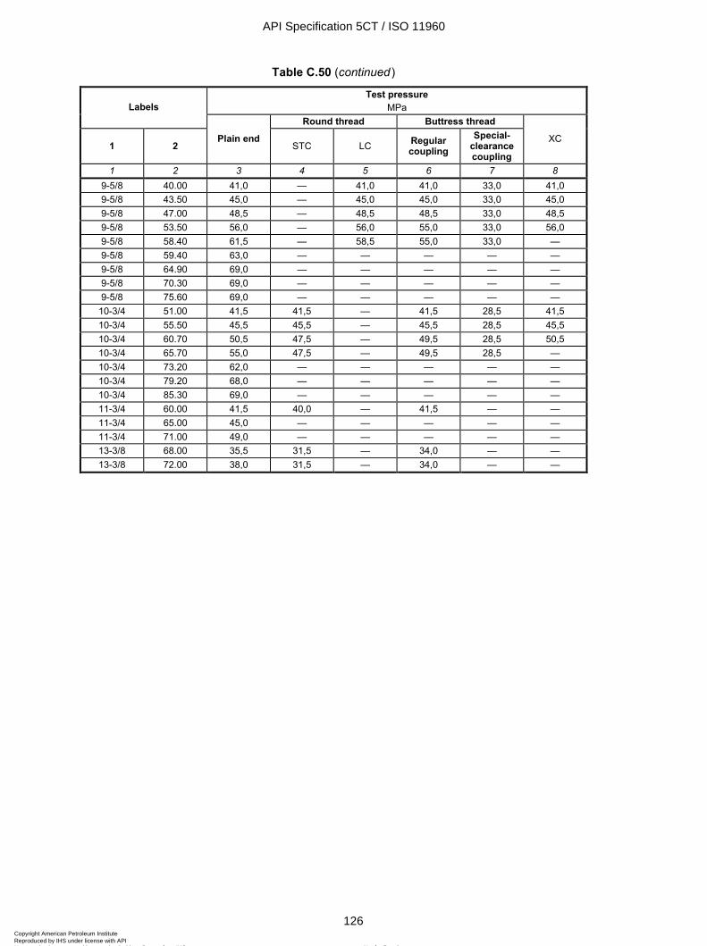
ISO 11960:2004(E)
126 © ISO 2004 – All rights reserved
Table C.50 (continued)
Test pressure MPa Labels
Round thread Buttress thread
1 2 Plain end
STC LC Regular coupling
Special-clearance coupling
XC
1 2 3 4 5 6 7 8 9-5/8 40.00 41,0 — 41,0 41,0 33,0 41,0 9-5/8 43.50 45,0 — 45,0 45,0 33,0 45,0 9-5/8 47.00 48,5 — 48,5 48,5 33,0 48,5 9-5/8 53.50 56,0 — 56,0 55,0 33,0 56,0 9-5/8 58.40 61,5 — 58,5 55,0 33,0 — 9-5/8 59.40 63,0 — — — — — 9-5/8 64.90 69,0 — — — — — 9-5/8 70.30 69,0 — — — — — 9-5/8 75.60 69,0 — — — — —
10-3/4 51.00 41,5 41,5 — 41,5 28,5 41,5 10-3/4 55.50 45,5 45,5 — 45,5 28,5 45,5 10-3/4 60.70 50,5 47,5 — 49,5 28,5 50,5 10-3/4 65.70 55,0 47,5 — 49,5 28,5 — 10-3/4 73.20 62,0 — — — — — 10-3/4 79.20 68,0 — — — — — 10-3/4 85.30 69,0 — — — — — 11-3/4 60.00 41,5 40,0 — 41,5 — — 11-3/4 65.00 45,0 — — — — — 11-3/4 71.00 49,0 — — — — — 13-3/8 68.00 35,5 31,5 — 34,0 — — 13-3/8 72.00 38,0 31,5 — 34,0 — —
API Specification 5CT / ISO 11960
126Copyright American Petroleum Institute Reproduced by IHS under license with API
Not for ResaleNo reproduction or networking permitted without license from IHS
--`,,,```-`-`,,`,,`,`,,`---
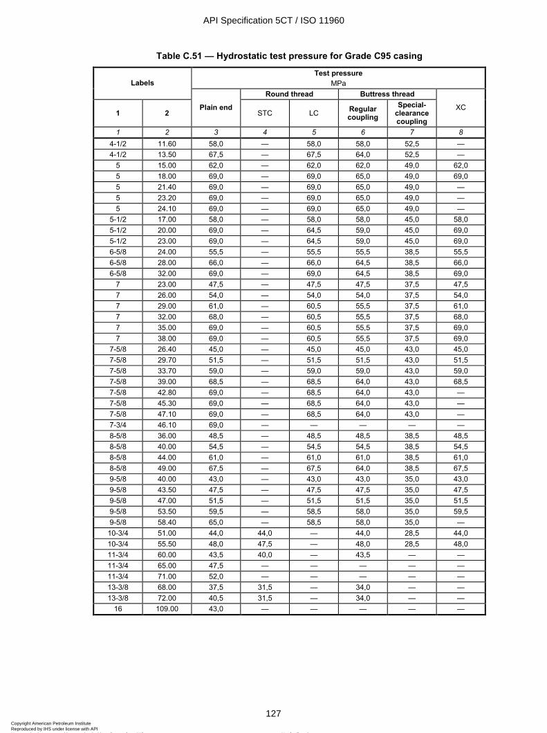
ISO 11960:2004(E)
© ISO 2004 – All rights reserved 127
Table C.51 — Hydrostatic test pressure for Grade C95 casing
Test pressure MPa Labels
Round thread Buttress thread
1 2 Plain end
STC LC Regular coupling
Special-clearance coupling
XC
1 2 3 4 5 6 7 8 4-1/2 11.60 58,0 — 58,0 58,0 52,5 — 4-1/2 13.50 67,5 — 67,5 64,0 52,5 —
5 15.00 62,0 — 62,0 62,0 49,0 62,0 5 18.00 69,0 — 69,0 65,0 49,0 69,0 5 21.40 69,0 — 69,0 65,0 49,0 — 5 23.20 69,0 — 69,0 65,0 49,0 — 5 24.10 69,0 — 69,0 65,0 49,0 —
5-1/2 17.00 58,0 — 58,0 58,0 45,0 58,0 5-1/2 20.00 69,0 — 64,5 59,0 45,0 69,0 5-1/2 23.00 69,0 — 64,5 59,0 45,0 69,0 6-5/8 24.00 55,5 — 55,5 55,5 38,5 55,5 6-5/8 28.00 66,0 — 66,0 64,5 38,5 66,0 6-5/8 32.00 69,0 — 69,0 64,5 38,5 69,0
7 23.00 47,5 — 47,5 47,5 37,5 47,5 7 26.00 54,0 — 54,0 54,0 37,5 54,0 7 29.00 61,0 — 60,5 55,5 37,5 61,0 7 32.00 68,0 — 60,5 55,5 37,5 68,0 7 35.00 69,0 — 60,5 55,5 37,5 69,0 7 38.00 69,0 — 60,5 55,5 37,5 69,0
7-5/8 26.40 45,0 — 45,0 45,0 43,0 45,0 7-5/8 29.70 51,5 — 51,5 51,5 43,0 51,5 7-5/8 33.70 59,0 — 59,0 59,0 43,0 59,0 7-5/8 39.00 68,5 — 68,5 64,0 43,0 68,5 7-5/8 42.80 69,0 — 68,5 64,0 43,0 — 7-5/8 45.30 69,0 — 68,5 64,0 43,0 — 7-5/8 47.10 69,0 — 68,5 64,0 43,0 — 7-3/4 46.10 69,0 — — — — — 8-5/8 36.00 48,5 — 48,5 48,5 38,5 48,5 8-5/8 40.00 54,5 — 54,5 54,5 38,5 54,5 8-5/8 44.00 61,0 — 61,0 61,0 38,5 61,0 8-5/8 49.00 67,5 — 67,5 64,0 38,5 67,5 9-5/8 40.00 43,0 — 43,0 43,0 35,0 43,0 9-5/8 43.50 47,5 — 47,5 47,5 35,0 47,5 9-5/8 47.00 51,5 — 51,5 51,5 35,0 51,5 9-5/8 53.50 59,5 — 58,5 58,0 35,0 59,5 9-5/8 58.40 65,0 — 58,5 58,0 35,0 —
10-3/4 51.00 44,0 44,0 — 44,0 28,5 44,0 10-3/4 55.50 48,0 47,5 — 48,0 28,5 48,0 11-3/4 60.00 43,5 40,0 — 43,5 — — 11-3/4 65.00 47,5 — — — — — 11-3/4 71.00 52,0 — — — — — 13-3/8 68.00 37,5 31,5 — 34,0 — — 13-3/8 72.00 40,5 31,5 — 34,0 — —
16 109.00 43,0 — — — — —
API Specification 5CT / ISO 11960
127Copyright American Petroleum Institute Reproduced by IHS under license with API
Not for ResaleNo reproduction or networking permitted without license from IHS
--`,,,```-`-`,,`,,`,`,,`---
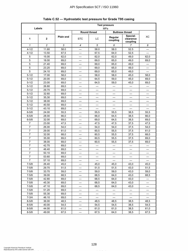
ISO 11960:2004(E)
128 © ISO 2004 – All rights reserved
Table C.52 — Hydrostatic test pressure for Grade T95 casing
Test pressure MPa Labels
Round thread Buttress thread
1 2 Plain end
STC LC Regular coupling
Special-clearance coupling
XC
1 2 3 4 5 6 7 8 4-1/2 11.60 58.0 — 58.0 58.0 52.5 — 4-1/2 13.50 67,5 — 67,5 64,0 52,5 —
5 15.00 62,0 — 62,0 62,0 49,0 62,0 5 18.00 69,0 — 69,0 65,0 49,0 69,0 5 21.40 69,0 — 69,0 65,0 49,0 — 5 23.20 69,0 — 69,0 65,0 49,0 — 5 24.10 69,0 — 69,0 65,0 49,0 —
5-1/2 17.00 58,0 — 58,0 58,0 45,0 58,0 5-1/2 20.00 69,0 — 64,5 59,0 45,0 69,0 5-1/2 23.00 69,0 — 64,5 59,0 45,0 69,0 5-1/2 26.80 69,0 — — — — — 5-1/2 29.70 69,0 — — — — — 5-1/2 32.60 69,0 — — — — — 5-1/2 35,30 69,0 — — — — — 5-1/2 38.00 69,0 — — — — — 5-1/2 40.50 69,0 — — — — — 5-1/2 43.10 69,0 — — — — — 6-5/8 24.00 55,5 — 55,5 55,5 38,5 55,5 6-5/8 28.00 66,0 — 66,0 64,5 38,5 66,0 6-5/8 32.00 69,0 — 69,0 64,5 38,5 69,0
7 23.00 47,5 — 47,5 47,5 37,5 47,5 7 26.00 54,0 — 54,0 54,0 37,5 54,0 7 29.00 61,0 — 60,5 55,5 37,5 61,0 7 32.00 68,0 — 60,5 55,5 37,5 68,0 7 35.00 69,0 — 60,5 55,5 37,5 69,0 7 38.00 69,0 — 60,5 55,5 37,5 69,0 7 42.70 69,0 — — — — — 7 46.40 69,0 — — — — — 7 50.10 69,0 — — — — — 7 53.60 69,0 — — — — — 7 57.10 69,0 — — — — —
7-5/8 26.40 45,0 — 45,0 45,0 43,0 45,0 7-5/8 29.70 51,5 — 51,5 51,5 43,0 51,5 7-5/8 33.70 59,0 — 59,0 59,0 43,0 59,0 7-5/8 39.00 68,5 — 68,5 64,0 43,0 68,5 7-5/8 42.80 69,0 — 68,5 64,0 43,0 — 7-5/8 45.30 69,0 — 68,5 64,0 43,0 — 7-5/8 47.10 69,0 — 68,5 64,0 43,0 — 7-5/8 51.20 69,0 — — — — — 7-5/8 55.30 69,0 — — — — — 7-3/4 46.10 69,0 — — — — — 8-5/8 36.00 48,5 — 48,5 48,5 38,5 48,5 8-5/8 40.00 54,5 — 54,5 54,5 38,5 54,5 8-5/8 44.00 61,0 — 61,0 61,0 38,5 61,0 8-5/8 49.00 67,5 — 67,5 64,0 38,5 67,5
API Specification 5CT / ISO 11960
128Copyright American Petroleum Institute Reproduced by IHS under license with API
Not for ResaleNo reproduction or networking permitted without license from IHS
--`,,,```-`-`,,`,,`,`,,`---
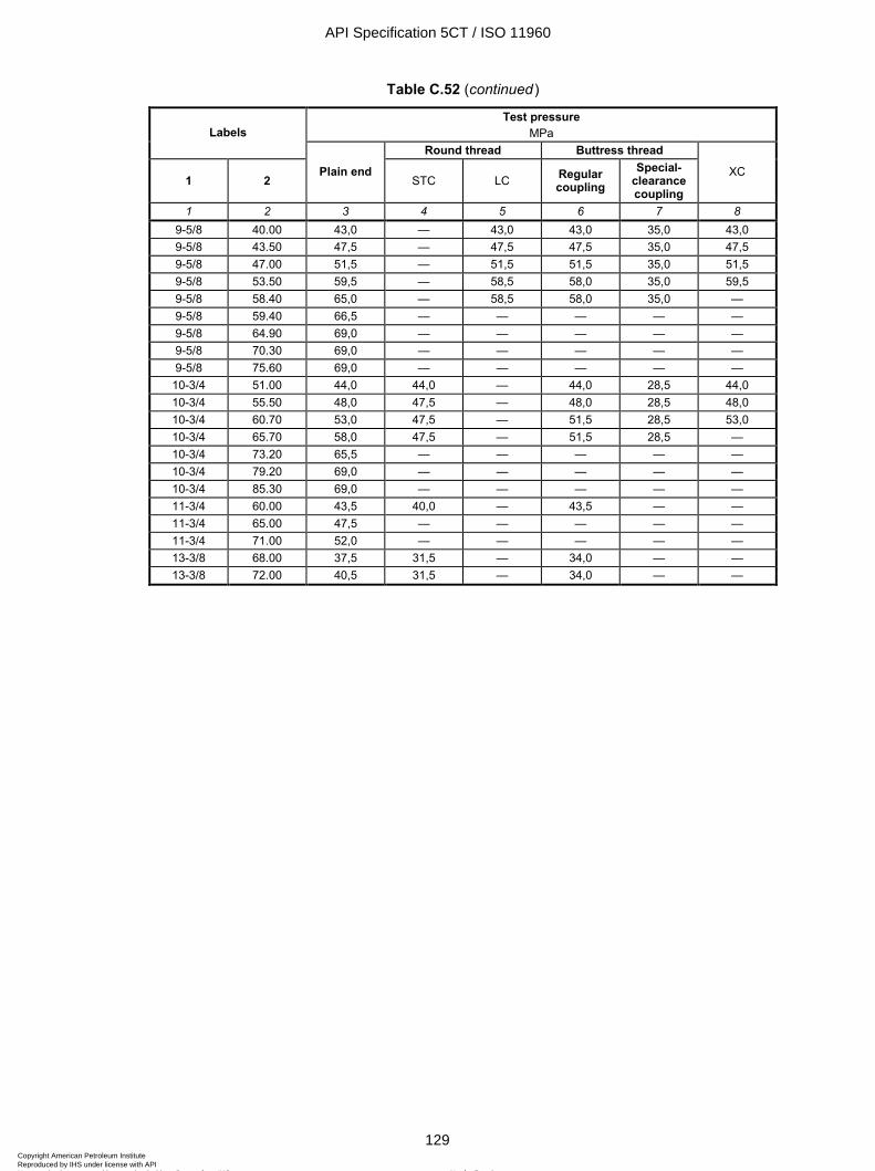
ISO 11960:2004(E)
© ISO 2004 – All rights reserved 129
Table C.52 (continued)
Test pressure MPa Labels
Round thread Buttress thread
1 2 Plain end
STC LC Regular coupling
Special-clearance coupling
XC
1 2 3 4 5 6 7 8 9-5/8 40.00 43,0 — 43,0 43,0 35,0 43,0 9-5/8 43.50 47,5 — 47,5 47,5 35,0 47,5 9-5/8 47.00 51,5 — 51,5 51,5 35,0 51,5 9-5/8 53.50 59,5 — 58,5 58,0 35,0 59,5 9-5/8 58.40 65,0 — 58,5 58,0 35,0 — 9-5/8 59.40 66,5 — — — — — 9-5/8 64.90 69,0 — — — — — 9-5/8 70.30 69,0 — — — — — 9-5/8 75.60 69,0 — — — — —
10-3/4 51.00 44,0 44,0 — 44,0 28,5 44,0 10-3/4 55.50 48,0 47,5 — 48,0 28,5 48,0 10-3/4 60.70 53,0 47,5 — 51,5 28,5 53,0 10-3/4 65.70 58,0 47,5 — 51,5 28,5 — 10-3/4 73.20 65,5 — — — — — 10-3/4 79.20 69,0 — — — — — 10-3/4 85.30 69,0 — — — — — 11-3/4 60.00 43,5 40,0 — 43,5 — — 11-3/4 65.00 47,5 — — — — — 11-3/4 71.00 52,0 — — — — — 13-3/8 68.00 37,5 31,5 — 34,0 — — 13-3/8 72.00 40,5 31,5 — 34,0 — —
API Specification 5CT / ISO 11960
129Copyright American Petroleum Institute Reproduced by IHS under license with API
Not for ResaleNo reproduction or networking permitted without license from IHS
--`,,,```-`-`,,`,,`,`,,`---
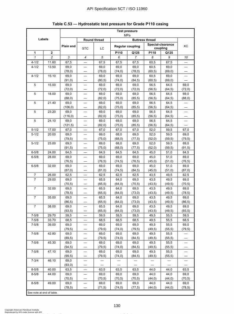
ISO 11960:2004(E)
130 © ISO 2004 – All rights reserved
Table C.53 — Hydrostatic test pressure for Grade P110 casing Test pressure
MPa Round thread Buttress thread Labels
Regular coupling Special-clearance coupling
1 2
Plain endSTC LC
P110 Q125 P110 Q125
XC
1 2 3 4 5 6 7 8 9 10 4-1/2 11.60 67,5 — 67,5 67,5 67,5 60,5 67,5 — 4-1/2 13.50 69,0
(78,0) — —
69,0 (78,0)
69,0 (74,0)
69,0 (78,0)
60,5 (60,5)
69,0 (69,0)
— —
4-1/2 15.10 69,0 (91,0)
— —
69,0 (80,5)
69,0 (74,0)
69,0 (84,5)
60,5 (60,5)
69,0 (69,0)
— —
5 15.00 69,0 (72,0)
— —
69,0 (72,0)
69,0 (72,0)
69,0 (72,0)
56,5 (56,5)
64,5 (64,5)
69,0 (72,0)
5 18.00 69,0 (88,0)
— —
69,0 (82,0)
69,0 (75,0)
69,0 (85,5)
56,5 (56,5)
64,5 (64,5)
69,0 (88,0)
5 21.40 69,0 (106,0)
— —
69,0 (82,0)
69,0 (75,0)
69,0 (85,5)
56,5 (56,5)
64,5 (64,5)
— —
5 23.20 69,0 (116,0)
— —
69,0 (82,0)
69,0 (75,0)
69,0 (85,5)
56,5 (56,5)
64,5 (64,5)
— —
5 24.10 69,0 (121,5)
— —
69,0 (82,0)
69,0 (75,0)
69,0 (85,5)
56,5 (56,5)
64,5 (64,5)
— —
5-1/2 17.00 67,0 — 67,0 67,0 67,0 52,0 59,5 67,0 5-1/2 20.00 69,0
(79,5) — —
69,0 (75,0)
68,0 (68,0)
69,0 (77,5)
52,0 (52,0)
59,5 (59,5)
69,0 (79,5)
5-1/2 23.00 69,0 (91,5)
— —
69,0 (75,0)
68,0 (68,0)
69,0 (77,5)
52,0 (52,0)
59,5 (59,5)
69,0 (91,5)
6-5/8 24.00 64,5 — 64,5 64,5 64,5 45,0 51,0 64,5 6-5/8 28.00 69,0
(76,5) — —
69,0 (76,5)
69,0 (74,5)
69,0 (76,5)
45,0 (45,0)
51,0 (51,0)
69,0 (76,5)
6-5/8 32.00 69,0 (87,0)
— —
69,0 (81,0)
69,0 (74,5)
69,0 (84,5)
45,0 (45,0)
51,0 (51,0)
69,0 (87,0)
7 26.00 62,5 — 62,5 62,5 62,5 43,5 49,5 62,5 7 29.00 69,0
(70,5) — —
65,5 (65,5)
64,0 (64,0)
69,0 (70,5)
43,5 (43,5)
49,5 (49,5)
69,0 (70,5)
7 32.00 69,0 (78,5)
— —
65,5 (65,5)
64,0 (64,0)
69,0 (73,0)
43,5 (43,5)
49,5 (49,5)
69,0 (78,5)
7 35.00 69,0 (86,5)
— —
65,5 (65,5)
64,0 (64,0)
69,0 (73,0)
43,5 (43,5)
49,5 (49,5)
69,0 (86,5)
7 38.00 69,0 (93,5)
— —
65,5 (65,5)
64,0 (64,0)
69,0 (73,0)
43,5 (43,5)
49,5 (49,5)
69,0 (93,5)
7-5/8 29.70 59,5 — 59,5 59,5 59,5 49,5 55,5 59,5 7-5/8 33.70 68,5 — 68,5 68,5 68,5 49,5 55,5 68,5 7-5/8 39.00 69,0
(79,5) — —
69,0 (79,5)
69,0 (74,0)
69,0 (79,5)
49,5 (49,5)
55,5 (55,5)
69,0 (79,5)
7-5/8 42.80 69,0 (89,5)
— —
69,0 (79,5)
69,0 (74,0)
69,0 (84,5)
49,5 (49,5)
55,5 (55,5)
— —
7-5/8 45.30 69,0 (94,5)
— —
69,0 (79,5)
69,0 (74,0)
69,0 (84,5)
49,5 (49,5)
55,5 (55,5)
— —
7-5/8 47.10 69,0 (99,5)
— —
69,0 (79,5)
69,0 (74,0)
69,0 (84,5)
49,5 (49,5)
55,5 (55,5)
— —
7-3/4 46.10 69,0 (93,0)
— —
— —
— —
— —
— —
— —
— —
8-5/8 40.00 63,5 — 63,5 63,5 63,5 44,0 44,0 63,5 8-5/8 44.00 69,0
(70,5) — —
69,0 (70,5)
69,0 (70,5)
69,0 (70,5)
44,0 (44,0)
44,0 (44,0)
69,0 (70,5)
8-5/8 49.00 69,0 (78,5)
— —
69,0 (71,5)
69,0 (74,0)
69,0 (77,5)
44,0 (44,0)
44,0 (44,0)
69,0 (78,5)
See note at end of table.
API Specification 5CT / ISO 11960
130Copyright American Petroleum Institute Reproduced by IHS under license with API
Not for ResaleNo reproduction or networking permitted without license from IHS
--`,,,```-`-`,,`,,`,`,,`---
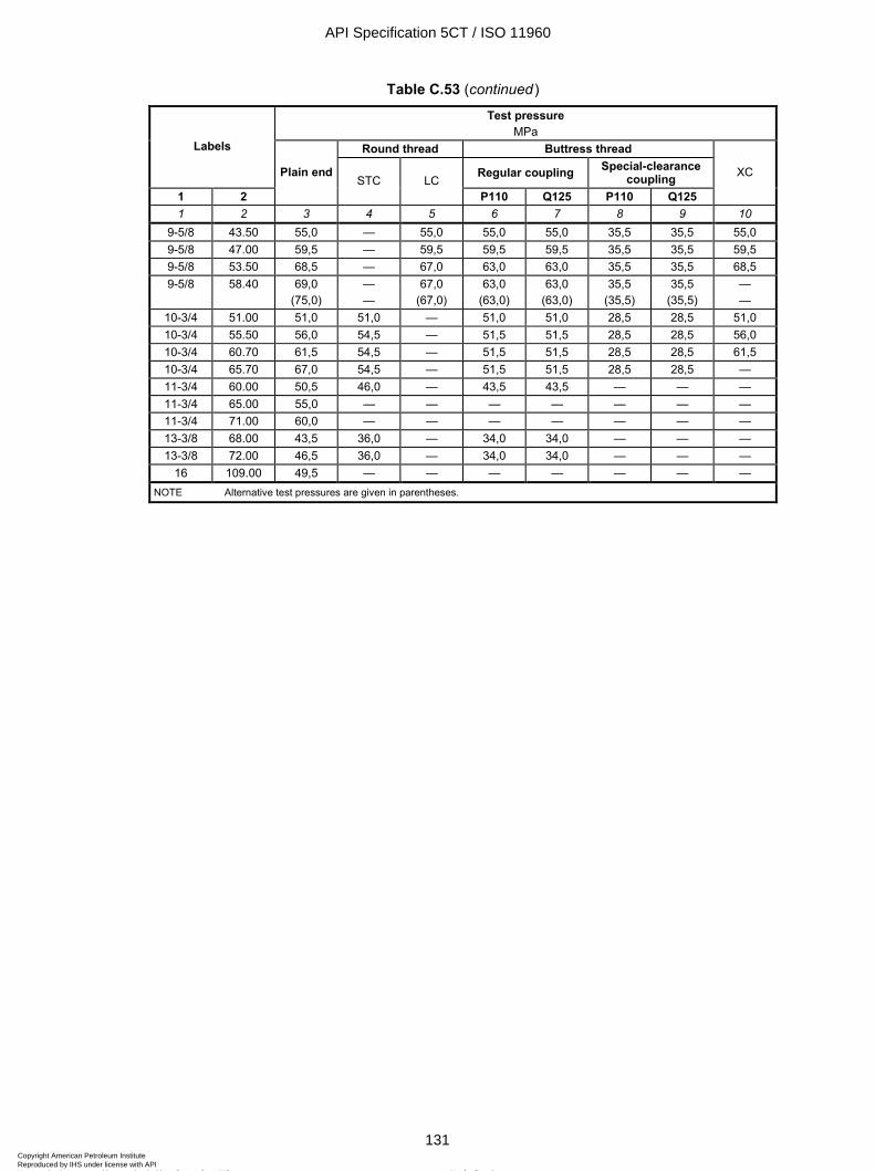
ISO 11960:2004(E)
© ISO 2004 – All rights reserved 131
Table C.53 (continued) Test pressure
MPa Round thread Buttress thread Labels
Regular coupling Special-clearance coupling
1 2
Plain end STC LC
P110 Q125 P110 Q125
XC
1 2 3 4 5 6 7 8 9 10 9-5/8 43.50 55,0 — 55,0 55,0 55,0 35,5 35,5 55,0 9-5/8 47.00 59,5 — 59,5 59,5 59,5 35,5 35,5 59,5 9-5/8 53.50 68,5 — 67,0 63,0 63,0 35,5 35,5 68,5 9-5/8 58.40 69,0
(75,0) — —
67,0 (67,0)
63,0 (63,0)
63,0 (63,0)
35,5 (35,5)
35,5 (35,5)
— —
10-3/4 51.00 51,0 51,0 — 51,0 51,0 28,5 28,5 51,0 10-3/4 55.50 56,0 54,5 — 51,5 51,5 28,5 28,5 56,0 10-3/4 60.70 61,5 54,5 — 51,5 51,5 28,5 28,5 61,5 10-3/4 65.70 67,0 54,5 — 51,5 51,5 28,5 28,5 — 11-3/4 60.00 50,5 46,0 — 43,5 43,5 — — — 11-3/4 65.00 55,0 — — — — — — — 11-3/4 71.00 60,0 — — — — — — — 13-3/8 68.00 43,5 36,0 — 34,0 34,0 — — — 13-3/8 72.00 46,5 36,0 — 34,0 34,0 — — —
16 109.00 49,5 — — — — — — — NOTE Alternative test pressures are given in parentheses.
API Specification 5CT / ISO 11960
131Copyright American Petroleum Institute Reproduced by IHS under license with API
Not for ResaleNo reproduction or networking permitted without license from IHS
--`,,,```-`-`,,`,,`,`,,`---
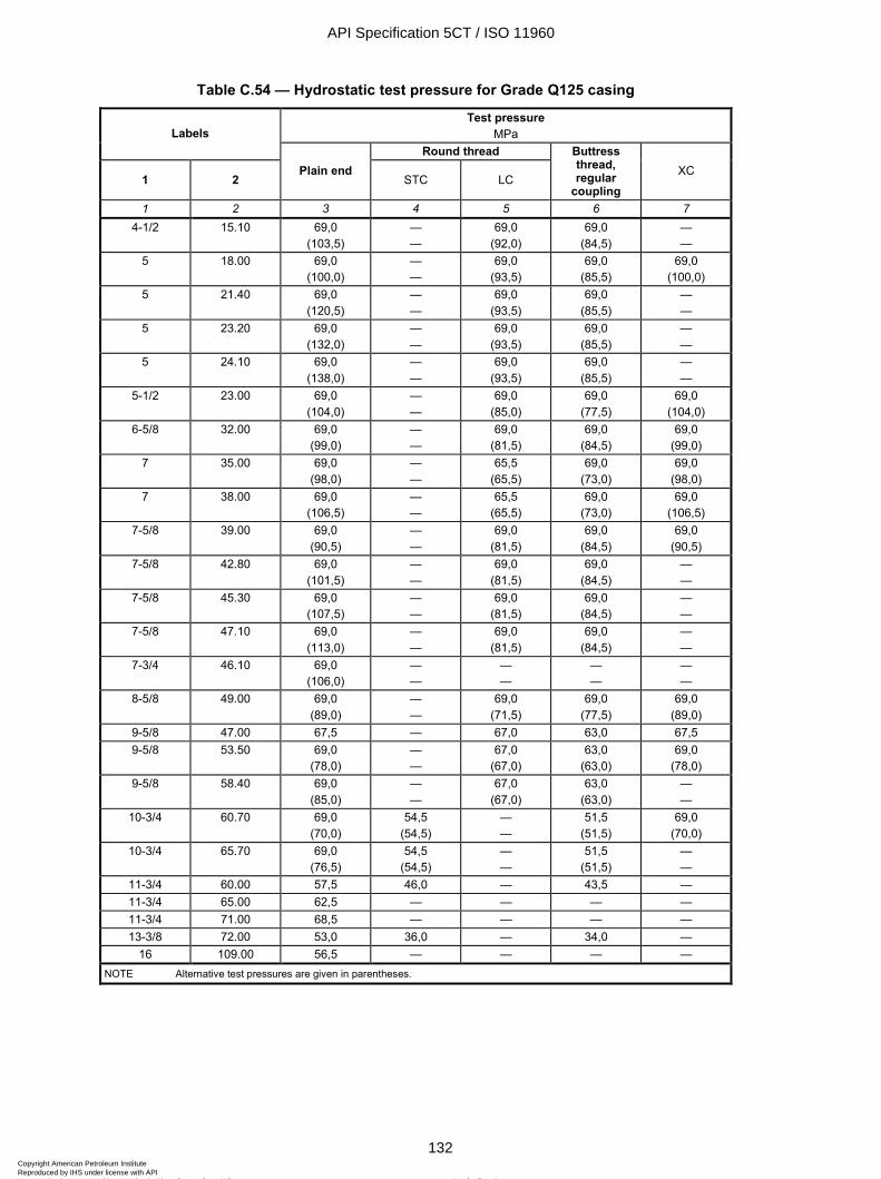
ISO 11960:2004(E)
132 © ISO 2004 – All rights reserved
Table C.54 — Hydrostatic test pressure for Grade Q125 casing
Test pressure MPa Labels
Round thread
1 2 Plain end
STC LC
Buttress thread, regular
coupling XC
1 2 3 4 5 6 7 4-1/2 15.10 69,0
(103,5) — —
69,0 (92,0)
69,0 (84,5)
— —
5 18.00 69,0 (100,0)
— —
69,0 (93,5)
69,0 (85,5)
69,0 (100,0)
5 21.40 69,0 (120,5)
— —
69,0 (93,5)
69,0 (85,5)
— —
5 23.20 69,0 (132,0)
— —
69,0 (93,5)
69,0 (85,5)
— —
5 24.10 69,0 (138,0)
— —
69,0 (93,5)
69,0 (85,5)
— —
5-1/2 23.00 69,0 (104,0)
— —
69,0 (85,0)
69,0 (77,5)
69,0 (104,0)
6-5/8 32.00 69,0 (99,0)
— —
69,0 (81,5)
69,0 (84,5)
69,0 (99,0)
7 35.00 69,0 (98,0)
— —
65,5 (65,5)
69,0 (73,0)
69,0 (98,0)
7 38.00 69,0 (106,5)
— —
65,5 (65,5)
69,0 (73,0)
69,0 (106,5)
7-5/8 39.00 69,0 (90,5)
— —
69,0 (81,5)
69,0 (84,5)
69,0 (90,5)
7-5/8 42.80 69,0 (101,5)
— —
69,0 (81,5)
69,0 (84,5)
— —
7-5/8 45.30 69,0 (107,5)
— —
69,0 (81,5)
69,0 (84,5)
— —
7-5/8 47.10 69,0 (113,0)
— —
69,0 (81,5)
69,0 (84,5)
— —
7-3/4 46.10 69,0 (106,0)
— —
— —
— —
— —
8-5/8 49.00 69,0 (89,0)
— —
69,0 (71,5)
69,0 (77,5)
69,0 (89,0)
9-5/8 47.00 67,5 — 67,0 63,0 67,5 9-5/8 53.50 69,0
(78,0) — —
67,0 (67,0)
63,0 (63,0)
69,0 (78,0)
9-5/8 58.40 69,0 (85,0)
— —
67,0 (67,0)
63,0 (63,0)
— —
10-3/4 60.70 69,0 (70,0)
54,5 (54,5)
— —
51,5 (51,5)
69,0 (70,0)
10-3/4 65.70 69,0 (76,5)
54,5 (54,5)
— —
51,5 (51,5)
— —
11-3/4 60.00 57,5 46,0 — 43,5 — 11-3/4 65.00 62,5 — — — — 11-3/4 71.00 68,5 — — — — 13-3/8 72.00 53,0 36,0 — 34,0 —
16 109.00 56,5 — — — — NOTE Alternative test pressures are given in parentheses.
API Specification 5CT / ISO 11960
132Copyright American Petroleum Institute Reproduced by IHS under license with API
Not for ResaleNo reproduction or networking permitted without license from IHS
--`,,,```-`-`,,`,,`,`,,`---
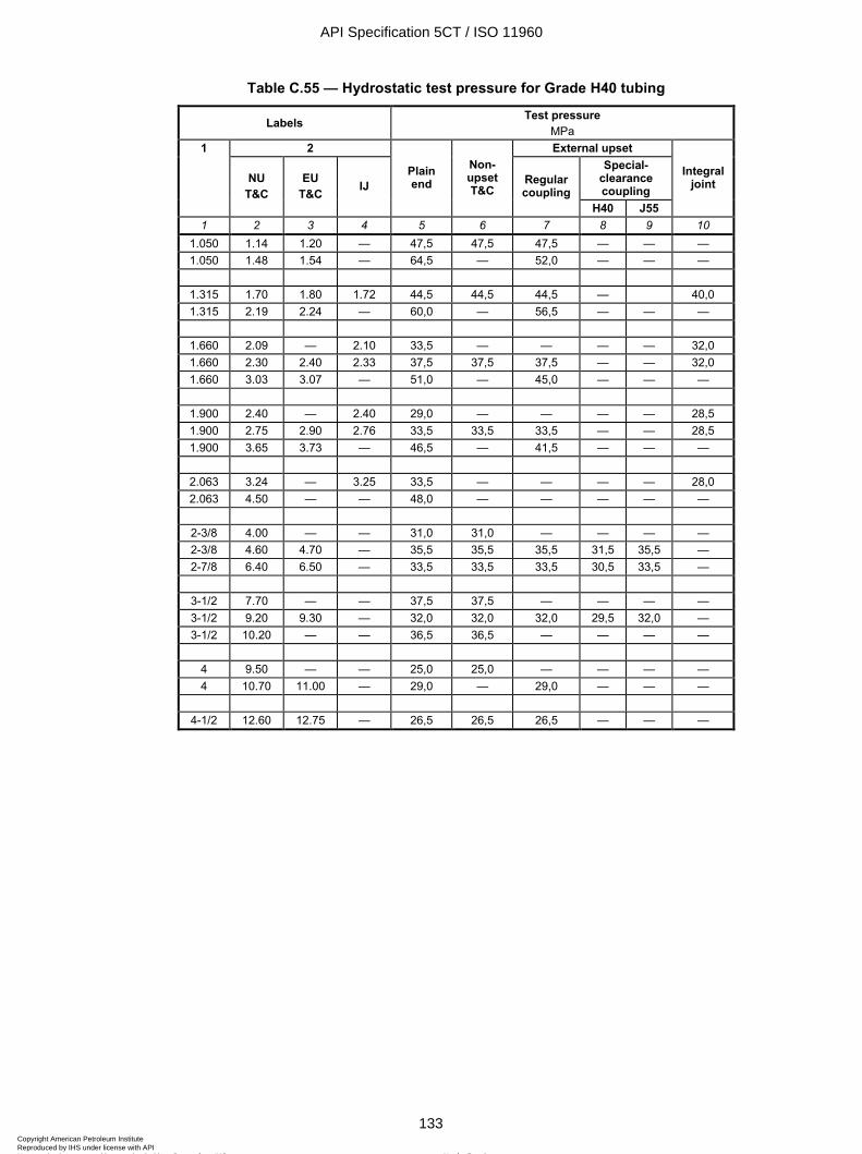
ISO 11960:2004(E)
© ISO 2004 – All rights reserved 133
Table C.55 — Hydrostatic test pressure for Grade H40 tubing
Labels Test pressure MPa
2 External upset Special-
clearance coupling
1
NU T&C
EU T&C IJ
Plain end
Non-upset T&C
Regular coupling
H40 J55
Integral joint
1 2 3 4 5 6 7 8 9 10 1.050 1.14 1.20 — 47,5 47,5 47,5 — — — 1.050 1.48 1.54 — 64,5 — 52,0 — — —
1.315 1.70 1.80 1.72 44,5 44,5 44,5 — 40,0 1.315 2.19 2.24 — 60,0 — 56,5 — — —
1.660 2.09 — 2.10 33,5 — — — — 32,0 1.660 2.30 2.40 2.33 37,5 37,5 37,5 — — 32,0 1.660 3.03 3.07 — 51,0 — 45,0 — — —
1.900 2.40 — 2.40 29,0 — — — — 28,5 1.900 2.75 2.90 2.76 33,5 33,5 33,5 — — 28,5 1.900 3.65 3.73 — 46,5 — 41,5 — — —
2.063 3.24 — 3.25 33,5 — — — — 28,0 2.063 4.50 — — 48,0 — — — — —
2-3/8 4.00 — — 31,0 31,0 — — — — 2-3/8 4.60 4.70 — 35,5 35,5 35,5 31,5 35,5 — 2-7/8 6.40 6.50 — 33,5 33,5 33,5 30,5 33,5 —
3-1/2 7.70 — — 37,5 37,5 — — — — 3-1/2 9.20 9.30 — 32,0 32,0 32,0 29,5 32,0 — 3-1/2 10.20 — — 36,5 36,5 — — — —
4 9.50 — — 25,0 25,0 — — — — 4 10.70 11.00 — 29,0 — 29,0 — — —
4-1/2 12.60 12.75 — 26,5 26,5 26,5 — — —
API Specification 5CT / ISO 11960
133Copyright American Petroleum Institute Reproduced by IHS under license with API
Not for ResaleNo reproduction or networking permitted without license from IHS
--`,,,```-`-`,,`,,`,`,,`---
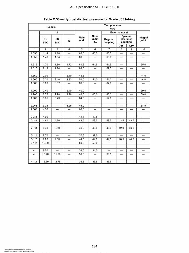
ISO 11960:2004(E)
134 © ISO 2004 – All rights reserved
Table C.56 — Hydrostatic test pressure for Grade J55 tubing
Labels Test pressure MPa
2 External upset Special-
clearance coupling
1
NU T&C
EU T&C IJ
Plain end
Non-upset T&C
Regular coupling
J55 L80
Integral joint
1 2 3 4 5 6 7 8 9 10 1.050 1.14 1.20 — 65,5 65,5 65,5 — — — 1.050 1.48 1.54 — 69,0 — 69,0 — — —
1.315 1.70 1.80 1.72 61,5 61,5 61,5 — 55,0 1.315 2.19 2.24 — 69,0 — 69,0 — — —
1.660 2.09 — 2.10 45,5 — — — — 44,0 1.660 2.30 2.40 2.33 51,0 51,0 51,0 — — 44,0 1.660 3.03 3.07 — 69,0 — 62,0 — — —
1.900 2.40 — 2.40 40,0 — — — — 39,0 1.900 2.75 2.90 2.76 46,0 46,0 46,0 — — 39,0 1.900 3.65 3.73 — 64,0 — 57,0 — — —
2.063 3.24 — 3.25 46,0 — — — — 38,5 2.063 4.50 — — 66,0 — — — — —
2-3/8 4.00 — — 42,5 42,5 — — — — 2-3/8 4.60 4.70 — 48,5 48,5 48,5 43,5 48,5 —
2-7/8 6.40 6.50 — 46,0 46,0 46,0 42,0 46,0 —
3-1/2 7.70 — — 37,5 37,5 — — — — 3-1/2 9.20 9.30 — 44,0 44,0 44,0 40,5 44,0 — 3-1/2 10.20 — — 50,0 50,0 — — — —
4 9.50 — — 34,5 34,5 — — — — 4 10.70 11.00 — 39,5 — 39,5 — — —
4-1/2 12.60 12.75 — 36,5 36,5 36,5 — — —
API Specification 5CT / ISO 11960
134Copyright American Petroleum Institute Reproduced by IHS under license with API
Not for ResaleNo reproduction or networking permitted without license from IHS
--`,,,```-`-`,,`,,`,`,,`---
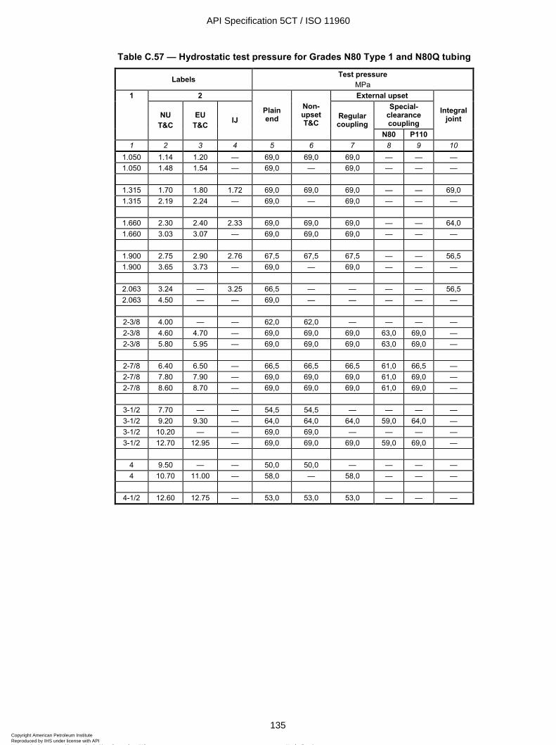
ISO 11960:2004(E)
© ISO 2004 – All rights reserved 135
Table C.57 — Hydrostatic test pressure for Grades N80 Type 1 and N80Q tubing
Labels Test pressure MPa
2 External upset Special-
clearance coupling
1
NU T&C
EU T&C IJ
Plain end
Non-upset T&C
Regular coupling
N80 P110
Integral joint
1 2 3 4 5 6 7 8 9 10 1.050 1.14 1.20 — 69,0 69,0 69,0 — — — 1.050 1.48 1.54 — 69,0 — 69,0 — — —
1.315 1.70 1.80 1.72 69,0 69,0 69,0 — — 69,0 1.315 2.19 2.24 — 69,0 — 69,0 — — —
1.660 2.30 2.40 2.33 69,0 69,0 69,0 — — 64,0 1.660 3.03 3.07 — 69,0 69,0 69,0 — — —
1.900 2.75 2.90 2.76 67,5 67,5 67,5 — — 56,5 1.900 3.65 3.73 — 69,0 — 69,0 — — —
2.063 3.24 — 3.25 66,5 — — — — 56,5 2.063 4.50 — — 69,0 — — — — —
2-3/8 4.00 — — 62,0 62,0 — — — — 2-3/8 4.60 4.70 — 69,0 69,0 69,0 63,0 69,0 — 2-3/8 5.80 5.95 — 69,0 69,0 69,0 63,0 69,0 —
2-7/8 6.40 6.50 — 66,5 66,5 66,5 61,0 66,5 — 2-7/8 7.80 7.90 — 69,0 69,0 69,0 61,0 69,0 — 2-7/8 8.60 8.70 — 69,0 69,0 69,0 61,0 69,0 —
3-1/2 7.70 — — 54,5 54,5 — — — — 3-1/2 9.20 9.30 — 64,0 64,0 64,0 59,0 64,0 — 3-1/2 10.20 — — 69,0 69,0 — — — — 3-1/2 12.70 12.95 — 69,0 69,0 69,0 59,0 69,0 —
4 9.50 — — 50,0 50,0 — — — — 4 10.70 11.00 — 58,0 — 58,0 — — —
4-1/2 12.60 12.75 — 53,0 53,0 53,0 — — —
API Specification 5CT / ISO 11960
135Copyright American Petroleum Institute Reproduced by IHS under license with API
Not for ResaleNo reproduction or networking permitted without license from IHS
--`,,,```-`-`,,`,,`,`,,`---
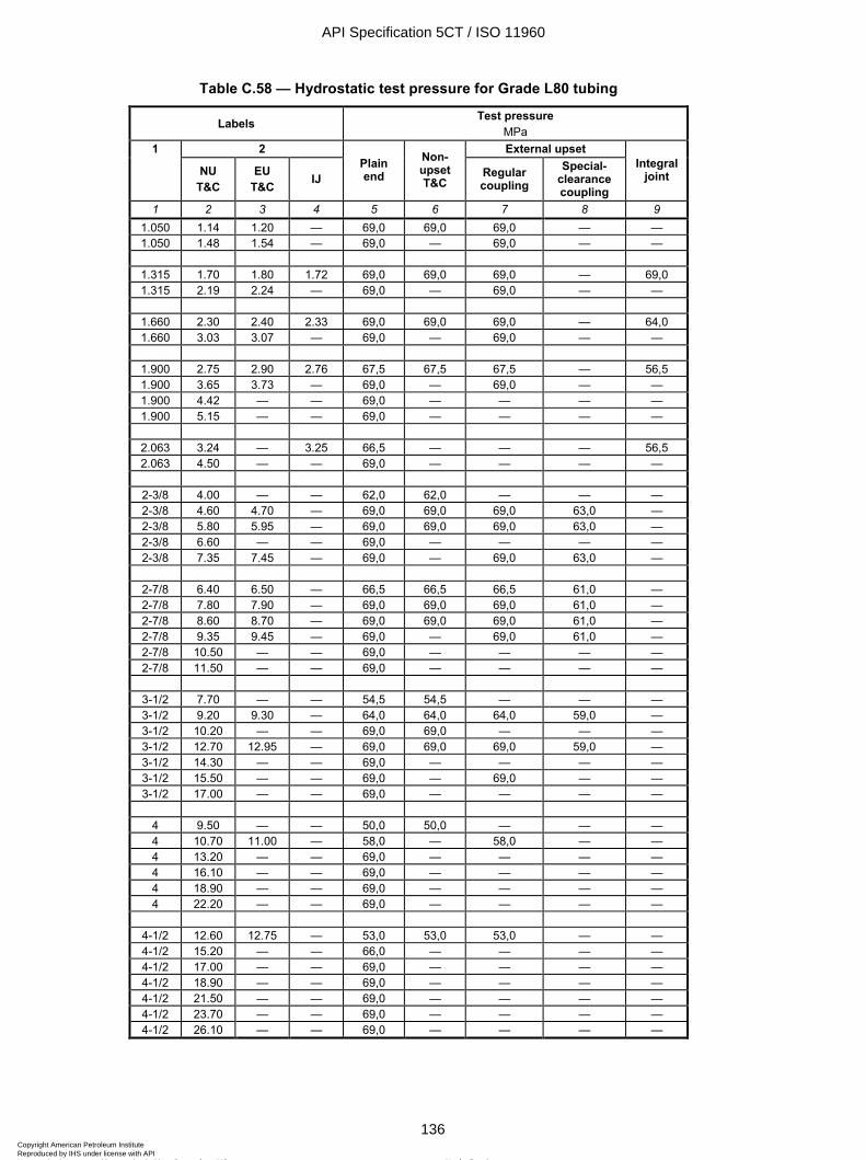
ISO 11960:2004(E)
136 © ISO 2004 – All rights reserved
Table C.58 — Hydrostatic test pressure for Grade L80 tubing
Labels Test pressure MPa
2 External upset 1
NU T&C
EU T&C IJ
Plain end
Non-upset T&C
Regular coupling
Special-clearance coupling
Integral joint
1 2 3 4 5 6 7 8 9 1.050 1.14 1.20 — 69,0 69,0 69,0 — — 1.050 1.48 1.54 — 69,0 — 69,0 — —
1.315 1.70 1.80 1.72 69,0 69,0 69,0 — 69,0 1.315 2.19 2.24 — 69,0 — 69,0 — —
1.660 2.30 2.40 2.33 69,0 69,0 69,0 — 64,0 1.660 3.03 3.07 — 69,0 — 69,0 — —
1.900 2.75 2.90 2.76 67,5 67,5 67,5 — 56,5 1.900 3.65 3.73 — 69,0 — 69,0 — — 1.900 4.42 — — 69,0 — — — — 1.900 5.15 — — 69,0 — — — —
2.063 3.24 — 3.25 66,5 — — — 56,5 2.063 4.50 — — 69,0 — — — —
2-3/8 4.00 — — 62,0 62,0 — — — 2-3/8 4.60 4.70 — 69,0 69,0 69,0 63,0 — 2-3/8 5.80 5.95 — 69,0 69,0 69,0 63,0 — 2-3/8 6.60 — — 69,0 — — — — 2-3/8 7.35 7.45 — 69,0 — 69,0 63,0 —
2-7/8 6.40 6.50 — 66,5 66,5 66,5 61,0 — 2-7/8 7.80 7.90 — 69,0 69,0 69,0 61,0 — 2-7/8 8.60 8.70 — 69,0 69,0 69,0 61,0 — 2-7/8 9.35 9.45 — 69,0 — 69,0 61,0 — 2-7/8 10.50 — — 69,0 — — — — 2-7/8 11.50 — — 69,0 — — — —
3-1/2 7.70 — — 54,5 54,5 — — — 3-1/2 9.20 9.30 — 64,0 64,0 64,0 59,0 — 3-1/2 10.20 — — 69,0 69,0 — — — 3-1/2 12.70 12.95 — 69,0 69,0 69,0 59,0 — 3-1/2 14.30 — — 69,0 — — — — 3-1/2 15.50 — — 69,0 — 69,0 — — 3-1/2 17.00 — — 69,0 — — — —
4 9.50 — — 50,0 50,0 — — — 4 10.70 11.00 — 58,0 — 58,0 — — 4 13.20 — — 69,0 — — — — 4 16.10 — — 69,0 — — — — 4 18.90 — — 69,0 — — — — 4 22.20 — — 69,0 — — — —
4-1/2 12.60 12.75 — 53,0 53,0 53,0 — — 4-1/2 15.20 — — 66,0 — — — — 4-1/2 17.00 — — 69,0 — — — — 4-1/2 18.90 — — 69,0 — — — — 4-1/2 21.50 — — 69,0 — — — — 4-1/2 23.70 — — 69,0 — — — — 4-1/2 26.10 — — 69,0 — — — —
API Specification 5CT / ISO 11960
136Copyright American Petroleum Institute Reproduced by IHS under license with API
Not for ResaleNo reproduction or networking permitted without license from IHS
--`,,,```-`-`,,`,,`,`,,`---
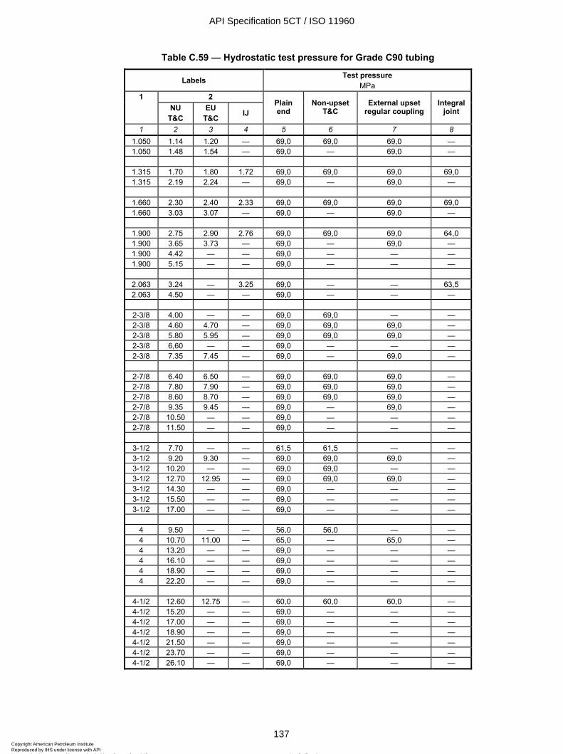
ISO 11960:2004(E)
© ISO 2004 – All rights reserved 137
Table C.59 — Hydrostatic test pressure for Grade C90 tubing
Labels Test pressure MPa
2 1 NU
T&C EU
T&C IJ Plain end
Non-upset T&C
External upset regular coupling
Integral joint
1 2 3 4 5 6 7 8 1.050 1.14 1.20 — 69,0 69,0 69,0 — 1.050 1.48 1.54 — 69,0 — 69,0 —
1.315 1.70 1.80 1.72 69,0 69,0 69,0 69,0 1.315 2.19 2.24 — 69,0 — 69,0 —
1.660 2.30 2.40 2.33 69,0 69,0 69,0 69,0 1.660 3.03 3.07 — 69,0 — 69,0 —
1.900 2.75 2.90 2.76 69,0 69,0 69,0 64,0 1.900 3.65 3.73 — 69,0 — 69,0 — 1.900 4.42 — — 69,0 — — — 1.900 5.15 — — 69,0 — — —
2.063 3.24 — 3.25 69,0 — — 63,5 2.063 4.50 — — 69,0 — — —
2-3/8 4.00 — — 69,0 69,0 — — 2-3/8 4.60 4.70 — 69,0 69,0 69,0 — 2-3/8 5.80 5.95 — 69,0 69,0 69,0 — 2-3/8 6,60 — — 69,0 — — — 2-3/8 7.35 7.45 — 69,0 — 69,0 —
2-7/8 6.40 6.50 — 69,0 69,0 69,0 — 2-7/8 7.80 7.90 — 69,0 69,0 69,0 — 2-7/8 8.60 8.70 — 69,0 69,0 69,0 — 2-7/8 9.35 9.45 — 69,0 — 69,0 — 2-7/8 10.50 — — 69,0 — — — 2-7/8 11.50 — — 69,0 — — —
3-1/2 7.70 — — 61,5 61,5 — — 3-1/2 9.20 9.30 — 69,0 69,0 69,0 — 3-1/2 10.20 — — 69,0 69,0 — — 3-1/2 12.70 12.95 — 69,0 69,0 69,0 — 3-1/2 14.30 — — 69,0 — — — 3-1/2 15.50 — — 69,0 — — — 3-1/2 17.00 — — 69,0 — — —
4 9.50 — — 56,0 56,0 — — 4 10.70 11.00 — 65,0 — 65,0 — 4 13.20 — — 69,0 — — — 4 16.10 — — 69,0 — — — 4 18.90 — — 69,0 — — — 4 22.20 — — 69,0 — — —
4-1/2 12.60 12.75 — 60,0 60,0 60,0 — 4-1/2 15.20 — — 69,0 — — — 4-1/2 17.00 — — 69,0 — — — 4-1/2 18.90 — — 69,0 — — — 4-1/2 21.50 — — 69,0 — — — 4-1/2 23.70 — — 69,0 — — — 4-1/2 26.10 — — 69,0 — — —
API Specification 5CT / ISO 11960
137Copyright American Petroleum Institute Reproduced by IHS under license with API
Not for ResaleNo reproduction or networking permitted without license from IHS
--`,,,```-`-`,,`,,`,`,,`---
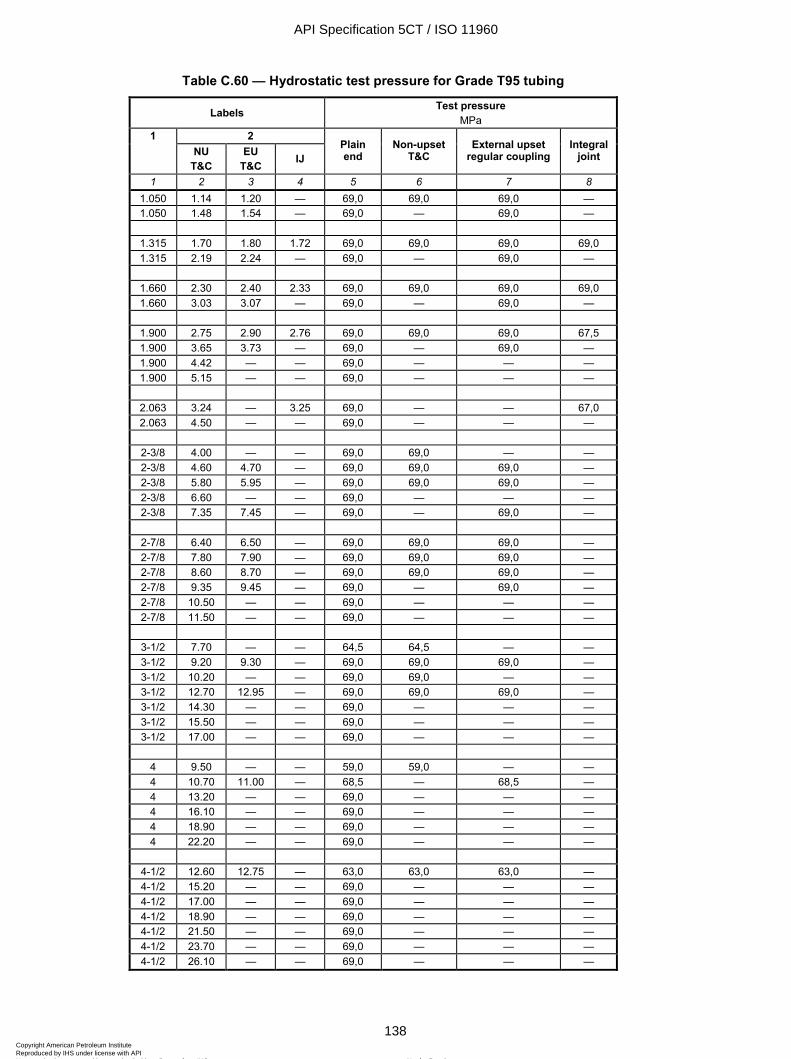
ISO 11960:2004(E)
138 © ISO 2004 – All rights reserved
Table C.60 — Hydrostatic test pressure for Grade T95 tubing
Labels Test pressure MPa
2 1 NU
T&C EU
T&C IJ Plain end
Non-upset T&C
External upset regular coupling
Integral joint
1 2 3 4 5 6 7 8 1.050 1.14 1.20 — 69,0 69,0 69,0 — 1.050 1.48 1.54 — 69,0 — 69,0 —
1.315 1.70 1.80 1.72 69,0 69,0 69,0 69,0 1.315 2.19 2.24 — 69,0 — 69,0 —
1.660 2.30 2.40 2.33 69,0 69,0 69,0 69,0 1.660 3.03 3.07 — 69,0 — 69,0 —
1.900 2.75 2.90 2.76 69,0 69,0 69,0 67,5 1.900 3.65 3.73 — 69,0 — 69,0 — 1.900 4.42 — — 69,0 — — — 1.900 5.15 — — 69,0 — — —
2.063 3.24 — 3.25 69,0 — — 67,0 2.063 4.50 — — 69,0 — — —
2-3/8 4.00 — — 69,0 69,0 — — 2-3/8 4.60 4.70 — 69,0 69,0 69,0 — 2-3/8 5.80 5.95 — 69,0 69,0 69,0 — 2-3/8 6.60 — — 69,0 — — — 2-3/8 7.35 7.45 — 69,0 — 69,0 —
2-7/8 6.40 6.50 — 69,0 69,0 69,0 — 2-7/8 7.80 7.90 — 69,0 69,0 69,0 — 2-7/8 8.60 8.70 — 69,0 69,0 69,0 — 2-7/8 9.35 9.45 — 69,0 — 69,0 — 2-7/8 10.50 — — 69,0 — — — 2-7/8 11.50 — — 69,0 — — —
3-1/2 7.70 — — 64,5 64,5 — — 3-1/2 9.20 9.30 — 69,0 69,0 69,0 — 3-1/2 10.20 — — 69,0 69,0 — — 3-1/2 12.70 12.95 — 69,0 69,0 69,0 — 3-1/2 14.30 — — 69,0 — — — 3-1/2 15.50 — — 69,0 — — — 3-1/2 17.00 — — 69,0 — — —
4 9.50 — — 59,0 59,0 — — 4 10.70 11.00 — 68,5 — 68,5 — 4 13.20 — — 69,0 — — — 4 16.10 — — 69,0 — — — 4 18.90 — — 69,0 — — — 4 22.20 — — 69,0 — — —
4-1/2 12.60 12.75 — 63,0 63,0 63,0 — 4-1/2 15.20 — — 69,0 — — — 4-1/2 17.00 — — 69,0 — — — 4-1/2 18.90 — — 69,0 — — — 4-1/2 21.50 — — 69,0 — — — 4-1/2 23.70 — — 69,0 — — — 4-1/2 26.10 — — 69,0 — — —
API Specification 5CT / ISO 11960
138Copyright American Petroleum Institute Reproduced by IHS under license with API
Not for ResaleNo reproduction or networking permitted without license from IHS
--`,,,```-`-`,,`,,`,`,,`---
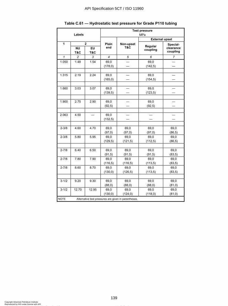
ISO 11960:2004(E)
© ISO 2004 – All rights reserved 139
Table C.61 — Hydrostatic test pressure for Grade P110 tubing
Test pressure MPa Labels
External upset 2 1
NU T&C
EU T&C
Plain end
Non-upset T&C Regular
coupling Special-
clearance coupling
1 2 3 4 5 6 7 1.050 1.48 1.54 69,0
(178,0) — —
69,0 (142,5)
— —
1.315 2.19 2.24 69,0
(165,0) — —
69,0 (154,5)
— —
1.660 3.03 3.07 69,0
(139,5) — —
69,0 (123,5)
— —
1.900 2.75 2.90 69,0
(92,5) — —
69,0 (92,5)
— —
2.063 4.50 — 69,0
(132,5) — —
— —
— —
2-3/8 4.60 4.70 69,0
(97,0) 69,0
(97,0) 69,0
(97,0) 69,0
(86,5) 2-3/8 5.80 5.95 69,0
(129,5) 69,0
(121,5) 69,0
(112,5) 69,0
(86,5)
2-7/8 6.40 6.50 69,0 (91,5)
69,0 (91,5)
69,0 (91,5)
69,0 (83,5)
2-7/8 7.80 7.90 69,0 (116,5)
69,0 (116,5)
69,0 (113,5)
69,0 (83,5)
2-7/8 8.60 8.70 69,0 (130,0)
69,0 (126,5)
69,0 (113,5)
69,0 (83,5)
3-1/2 9.20 9.30 69,0
(88,0) 69,0
(88,0) 69,0
(88,0) 69,0
(81,0) 3-1/2 12.70 12.95 69,0
(130,0) 69,0
(124,0) 69,0
(118,0) 69,0
(81,0) NOTE Alternative test pressures are given in parentheses.
API Specification 5CT / ISO 11960
139Copyright American Petroleum Institute Reproduced by IHS under license with API
Not for ResaleNo reproduction or networking permitted without license from IHS
--`,,,```-`-`,,`,,`,`,,`---
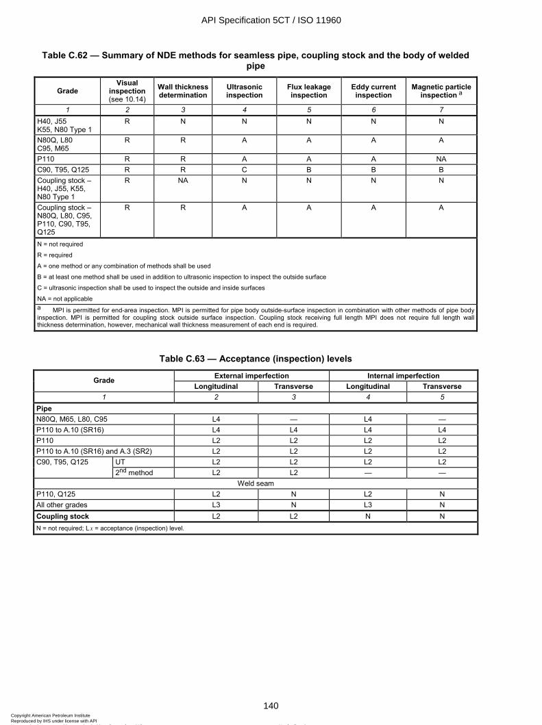
ISO 11960:2004(E)
140 © ISO 2004 – All rights reserved
Table C.62 — Summary of NDE methods for seamless pipe, coupling stock and the body of welded pipe
Grade Visual
inspection (see 10.14)
Wall thickness determination
Ultrasonic inspection
Flux leakage inspection
Eddy current inspection
Magnetic particle inspection a
1 2 3 4 5 6 7 H40, J55 K55, N80 Type 1
R N N N N N
N80Q, L80 C95, M65
R R A A A A
P110 R R A A A NA C90, T95, Q125 R R C B B B Coupling stock – H40, J55, K55, N80 Type 1
R NA N N N N
Coupling stock – N80Q, L80, C95, P110, C90, T95, Q125
R R A A A A
N = not required
R = required
A = one method or any combination of methods shall be used
B = at least one method shall be used in addition to ultrasonic inspection to inspect the outside surface
C = ultrasonic inspection shall be used to inspect the outside and inside surfaces
NA = not applicable a MPI is permitted for end-area inspection. MPI is permitted for pipe body outside-surface inspection in combination with other methods of pipe body inspection. MPI is permitted for coupling stock outside surface inspection. Coupling stock receiving full length MPI does not require full length wall thickness determination, however, mechanical wall thickness measurement of each end is required.
Table C.63 — Acceptance (inspection) levels
External imperfection Internal imperfection Grade Longitudinal Transverse Longitudinal Transverse
1 2 3 4 5 Pipe N80Q, M65, L80, C95 L4 — L4 — P110 to A.10 (SR16) L4 L4 L4 L4 P110 L2 L2 L2 L2 P110 to A.10 (SR16) and A.3 (SR2) L2 L2 L2 L2
UT L2 L2 L2 L2 C90, T95, Q125 2nd method L2 L2 — —
Weld seam P110, Q125 L2 N L2 N All other grades L3 N L3 N Coupling stock L2 L2 N N N = not required; L x = acceptance (inspection) level.
API Specification 5CT / ISO 11960
140Copyright American Petroleum Institute Reproduced by IHS under license with API
Not for ResaleNo reproduction or networking permitted without license from IHS
--`,,,```-`-`,,`,,`,`,,`---

ISO 11960:2004(E)
© ISO 2004 – All rights reserved 141
Table C.64 — Artificial reference indicators
Acceptance (inspection) level
Notch depth a max.
%
Notch length max. at full depth
mm
Width max. mm
Radially drilled hole diameter b
mm 1 2 3 4 5
L2 5 50 1 1,6 L3 10 50 1 3,2 L4 12,5 50 1 3,2
NOTE See Figure D.17. a Depth as a percent of specified wall thickness. The depth tolerance shall be ± 15 % of the calculated notch depth with a minimum notch depth of 0,3 mm ± 0,05 mm. b Drilled hole diameter (through the pipe wall) shall be based on the drill bit size.
Table C.65 — Size of stamp markings
Product Label 1 Marking height mm
Pipe < 4-1/2 W 4-1/2
4,8 6,4
Coupling For pipe sizes < 4-1/2 For pipe sizes W 4-1/2 to < 7-5/8
For pipe sizes W 7-5/8
6,4 9,5
12,7
API Specification 5CT / ISO 11960
141Copyright American Petroleum Institute Reproduced by IHS under license with API
Not for ResaleNo reproduction or networking permitted without license from IHS
--`,,,```-`-`,,`,,`,`,,`---

ISO 11960:2004(E)
142 © ISO 2004 – All rights reserved
Table C.66 — Grade colour codes
Colour(s) for couplings Grade Grade type
Number and colour of bands for pipe, coupling stock and pup joints WWWW 1,8 m Entire coupling Band(s) a
1 2 3 4 5 H40 None or black band at the manufacturer’s option None Same as for pipe J55
tubing One bright green Bright green None
J55 casing
One bright green Bright green One white
K55 Two bright green Bright green None M65 One bright green, one blue M65 pipe uses L80 Type 1 couplings N80 1 One red Red None N80 Q One red, one bright green Red Green L80 1 One red, one brown Red One brown L80 9Cr One red, one brown, two yellow Red Two yellow L80 13Cr One red, one brown, one yellow Red One yellow C90 1 One purple Purple None C90 2 One purple, one yellow Purple One yellow T95 1 One silver Silver None T95 2 One silver, one yellow Silver One yellow C95 One brown Brown None P110 One white White None Q125 1 One orange Orange None Q125 2 One orange, one yellow Orange One yellow Q125 3 One orange, one green Orange One green Q125 4 One orange, one brown Orange One brown
a Special-clearance couplings shall also have a black band.
Table C.67 — Thread type markings
Product Thread type Marked symbol Casing Short round
Long round Buttress
Extreme-line
STC LC BC XC
Tubing Non-upset External upset Integral joint
NU EU IJ
API Specification 5CT / ISO 11960
142Copyright American Petroleum Institute Reproduced by IHS under license with API
Not for ResaleNo reproduction or networking permitted without license from IHS
--`,,,```-`-`,,`,,`,`,,`---
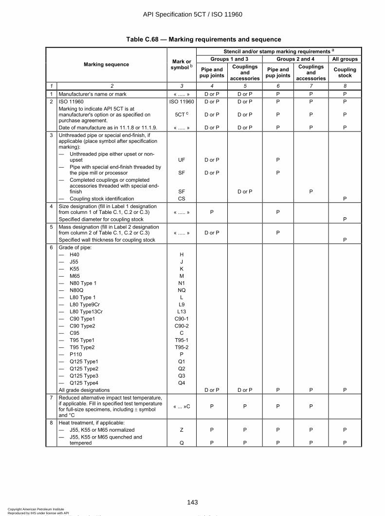
ISO 11960:2004(E)
© ISO 2004 – All rights reserved 143
Table C.68 — Marking requirements and sequence
Stencil and/or stamp marking requirements a
Groups 1 and 3 Groups 2 and 4 All groups Marking sequence Mark or
symbol b Pipe and pup joints
Couplings and
accessoriesPipe and
pup joints Couplings
and accessories
Coupling stock
1 2 3 4 5 6 7 8 1 Manufacturer’s name or mark « ..... » D or P D or P P P P 2 ISO 11960
Marking to indicate API 5CT is at manufacturer's option or as specified on purchase agreement. Date of manufacture as in 11.1.8 or 11.1.9.
ISO 11960
5CT c
« ..... »
D or P
D or P
D or P
D or P
D or P
D or P
P
P
P
P
P
P
P
P
P 3 Unthreaded pipe or special end-finish, if
applicable (place symbol after specification marking): — Unthreaded pipe either upset or non-
upset — Pipe with special end-finish threaded by
the pipe mill or processor — Completed couplings or completed
accessories threaded with special end-finish
— Coupling stock identification
UF
SF
SF CS
D or P
D or P
D or P
P
P
P P
4 Size designation (fill in Label 1 designation from column 1 of Table C.1, C.2 or C.3) Specified diameter for coupling stock
« ..... »
P
P
P 5 Mass designation (fill in Label 2 designation
from column 2 of Table C.1, C.2 or C.3) Specified wall thickness for coupling stock
« ..... »
D or P
P
P 6 Grade of pipe:
— H40 — J55 — K55 — M65 — N80 Type 1 — N80Q — L80 Type 1 — L80 Type9Cr — L80 Type13Cr — C90 Type1 — C90 Type2 — C95 — T95 Type1 — T95 Type2 — P110 — Q125 Type1 — Q125 Type2 — Q125 Type3 — Q125 Type4 All grade designations
H J K M N1 NQ L L9
L13 C90-1 C90-2
C T95-1 T95-2
P Q1 Q2 Q3 Q4
D or P D or P P P P 7 Reduced alternative impact test temperature,
if applicable. Fill in specified test temperature for full-size specimens, including ± symbol and °C
« ... »C P P P P
8 Heat treatment, if applicable: — J55, K55 or M65 normalized — J55, K55 or M65 quenched and
tempered
Z
Q
P
P
P
P
P
P
P
P
P
P
API Specification 5CT / ISO 11960
143Copyright American Petroleum Institute Reproduced by IHS under license with API
Not for ResaleNo reproduction or networking permitted without license from IHS
--`,,,```-`-`,,`,,`,`,,`---
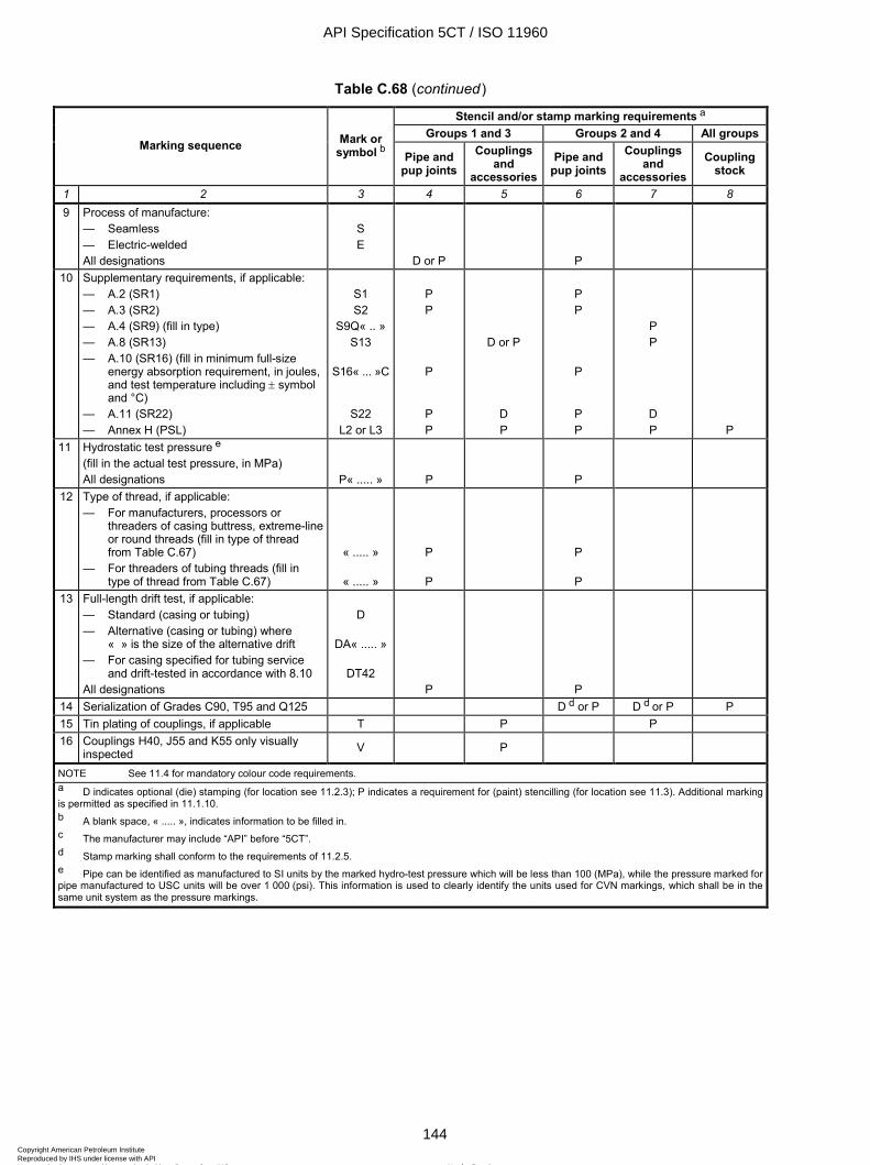
ISO 11960:2004(E)
144 © ISO 2004 – All rights reserved
Table C.68 (continued)
Stencil and/or stamp marking requirements a
Groups 1 and 3 Groups 2 and 4 All groups Marking sequence Mark or
symbol b Pipe and pup joints
Couplings and
accessoriesPipe and
pup joints Couplings
and accessories
Coupling stock
1 2 3 4 5 6 7 8 9 Process of manufacture:
— Seamless — Electric-welded All designations
S E
D or P
P
10 Supplementary requirements, if applicable: — A.2 (SR1) — A.3 (SR2) — A.4 (SR9) (fill in type) — A.8 (SR13) — A.10 (SR16) (fill in minimum full-size
energy absorption requirement, in joules, and test temperature including ± symbol and °C)
— A.11 (SR22) — Annex H (PSL)
S1 S2
S9Q« .. » S13
S16« ... »C
S22 L2 or L3
P P
P
P P
D or P
D P
P P
P
P P
P P
D P P
11 Hydrostatic test pressure e (fill in the actual test pressure, in MPa) All designations P« ..... » P
P
12 Type of thread, if applicable: — For manufacturers, processors or
threaders of casing buttress, extreme-line or round threads (fill in type of thread from Table C.67)
— For threaders of tubing threads (fill in type of thread from Table C.67)
« ..... »
« ..... »
P
P
P
P
13 Full-length drift test, if applicable: — Standard (casing or tubing) — Alternative (casing or tubing) where
« » is the size of the alternative drift — For casing specified for tubing service
and drift-tested in accordance with 8.10 All designations
D
DA« ..... »
DT42 P
P
14 Serialization of Grades C90, T95 and Q125 D d or P D d or P P 15 Tin plating of couplings, if applicable T P P 16 Couplings H40, J55 and K55 only visually
inspected V P
NOTE See 11.4 for mandatory colour code requirements. a D indicates optional (die) stamping (for location see 11.2.3); P indicates a requirement for (paint) stencilling (for location see 11.3). Additional marking is permitted as specified in 11.1.10. b A blank space, « ..... », indicates information to be filled in. c The manufacturer may include “API” before “5CT”. d Stamp marking shall conform to the requirements of 11.2.5. e Pipe can be identified as manufactured to SI units by the marked hydro-test pressure which will be less than 100 (MPa), while the pressure marked for pipe manufactured to USC units will be over 1 000 (psi). This information is used to clearly identify the units used for CVN markings, which shall be in the same unit system as the pressure markings.
API Specification 5CT / ISO 11960
144Copyright American Petroleum Institute Reproduced by IHS under license with API
Not for ResaleNo reproduction or networking permitted without license from IHS
--`,,,```-`-`,,`,,`,`,,`---
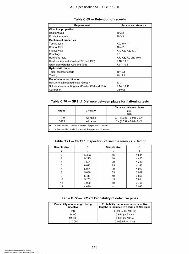
ISO 11960:2004(E)
© ISO 2004 – All rights reserved 145
Table C.69 — Retention of records
Requirement Subclause reference Chemical properties Heat analysis Product analysis
10.3.2 10.3.3
Mechanical properties Tensile tests Control tests Impact tests Couplings Hardness tests Hardenability test (Grades C90 and T95) Grain size (Grades C90 and T95)
7.2, 10.4.7 10.4.2 7.4, 7.5, 7.6, 10.7 9.5 7.7, 7.8, 7.9 and 10.6 7.10, 10.9 7.11, 10.8
Hydrostatic tests Tester recorder charts Testing
10.12.1 10.12.1
Manufacturer certification Results of all required tests (Group 4) Sulfide stress-cracking test (Grades C90 and T95) Calibration
13.3 7.14, 10.10 Various
Table C.70 — SR11.1 Distance between plates for flattening tests
Grade D/t ratio Distance between plates
mm max.
P110 Q125
All ratios All ratios
D × (1,086 – 0,016 3 D/t) D × (1,092 – 0,014 0 D/t)
D is the specified outside diameter of pipe, in millimetres.
t is the specified wall thickness of the pipe, in millimetres.
Table C.71 — SR12.1 Inspection lot sample sizes vs. F factor
Sample size F Sample size F 1 2 3 4 3 4 5 6 7 8 9 10 12 14
13,857 9,215 7,501 6,612 6,061 5,686 5,414 5,203 4,900 4,690
16 18 20 25 30 35 40 45 50 ∞
4,534 4,415 4,319 4,143 4,022 3,937 3,866 3,811 3,766 3,090
Table C.72 — SR12.2 Probability of defective pipes
Probability of one length being defective
Probability that one or more defective lengths is included in a string of 100 pipes
1/10 1/100
1/1 000 1/10 000
0,999 97 (or 100 %) 0,634 (or 63 %) 0,095 (or 10 %)
0,009 95 (or 1 %)
API Specification 5CT / ISO 11960
145Copyright American Petroleum Institute Reproduced by IHS under license with API
Not for ResaleNo reproduction or networking permitted without license from IHS
--`,,,```-`-`,,`,,`,`,,`---
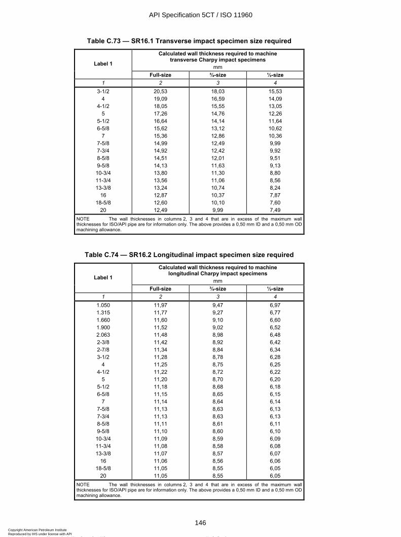
ISO 11960:2004(E)
146 © ISO 2004 – All rights reserved
Table C.73 — SR16.1 Transverse impact specimen size required
Calculated wall thickness required to machine transverse Charpy impact specimens
mm Label 1
Full-size ¾-size ½-size 1 2 3 4
3-1/2 4
4-1/2 5
5-1/2 6-5/8
7 7-5/8 7-3/4 8-5/8 9-5/8 10-3/4 11-3/4 13-3/8
16 18-5/8
20
20,53 19,09 18,05 17,26 16,64 15,62 15,36 14,99 14,92 14,51 14,13 13,80 13,56 13,24 12,87 12,60 12,49
18,03 16,59 15,55 14,76 14,14 13,12 12,86 12,49 12,42 12,01 11,63 11,30 11,06 10,74 10,37 10,10 9,99
15,53 14,09 13,05 12,26 11,64 10,62 10,36 9,99 9,92 9,51 9,13 8,80 8,56 8,24 7,87 7,60 7,49
NOTE The wall thicknesses in columns 2, 3 and 4 that are in excess of the maximum wall thicknesses for ISO/API pipe are for information only. The above provides a 0,50 mm ID and a 0,50 mm OD machining allowance.
Table C.74 — SR16.2 Longitudinal impact specimen size required
Calculated wall thickness required to machine longitudinal Charpy impact specimens
mm Label 1
Full-size ¾-size ½-size 1 2 3 4
1.050 1.315 1.660 1.900 2.063 2-3/8 2-7/8 3-1/2
4 4-1/2
5 5-1/2 6-5/8
7 7-5/8 7-3/4 8-5/8 9-5/8 10-3/4 11-3/4 13-3/8
16 18-5/8
20
11,97 11,77 11,60 11,52 11,48 11,42 11,34 11,28 11,25 11,22 11,20 11,18 11,15 11,14 11,13 11,13 11,11 11,10 11,09 11,08 11,07 11,06 11,05 11,05
9,47 9,27 9,10 9,02 8,98 8,92 8,84 8,78 8,75 8,72 8,70 8,68 8,65 8,64 8,63 8,63 8,61 8,60 8,59 8,58 8,57 8,56 8,55 8,55
6,97 6,77 6,60 6,52 6,48 6,42 6,34 6,28 6,25 6,22 6,20 6,18 6,15 6,14 6,13 6,13 6,11 6,10 6,09 6,08 6,07 6,06 6,05 6,05
NOTE The wall thicknesses in columns 2, 3 and 4 that are in excess of the maximum wall thicknesses for ISO/API pipe are for information only. The above provides a 0,50 mm ID and a 0,50 mm OD machining allowance.
API Specification 5CT / ISO 11960
146Copyright American Petroleum Institute Reproduced by IHS under license with API
Not for ResaleNo reproduction or networking permitted without license from IHS
--`,,,```-`-`,,`,,`,`,,`---
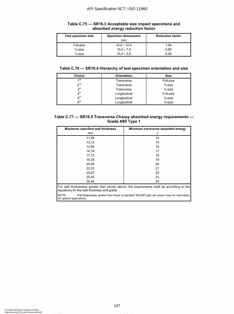
ISO 11960:2004(E)
© ISO 2004 – All rights reserved 147
Table C.75 — SR16.3 Acceptable size impact specimens and absorbed energy reduction factor
Test specimen size Specimen dimensions mm
Reduction factor
Full-size 10,0 × 10,0 1,00 ¾-size 10,0 × 7,5 0,80 ½-size 10,0 × 5,0 0,55
Table C.76 — SR16.4 Hierarchy of test specimen orientation and size
Choice Orientation Size 1st 2nd 3rd 4th 5th 6th
Transverse Transverse Transverse Longitudinal Longitudinal Longitudinal
Full-size ¾-size ½-size
Full-size ¾-size ½-size
Table C.77 — SR16.5 Transverse Charpy absorbed energy requirements — Grade N80 Type 1
Maximum specified wall thickness mm
Minimum transverse absorbed energy J
11,59 13,12 14,66 16,19 17,73 19,26 20,80 22,33 23,87 25,40 26,94
14 15 16 17 18 19 20 21 22 23 24
For wall thicknesses greater than shown above, the requirements shall be according to the equations for the wall thickness and grade. NOTE Wall thicknesses greater than those of standard ISO/API pipe are shown here for information for special applications.
API Specification 5CT / ISO 11960
147Copyright American Petroleum Institute Reproduced by IHS under license with API
Not for ResaleNo reproduction or networking permitted without license from IHS
--`,,,```-`-`,,`,,`,`,,`---
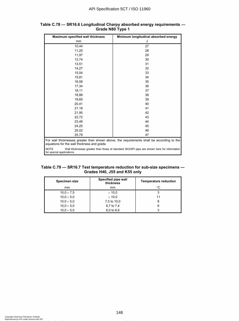
ISO 11960:2004(E)
148 © ISO 2004 – All rights reserved
Table C.78 — SR16.6 Longitudinal Charpy absorbed energy requirements — Grade N80 Type 1
Maximum specified wall thickness mm
Minimum longitudinal absorbed energy J
10,44 11,20 11,97 12,74 13,51 14,27 15,04 15,81 16,58 17,34 18,11 18,88 19,65 20,41 21,18 21,95 22,72 23,48 24,25 25,02 25,79
27 28 29 30 31 32 33 34 35 36 37 38 39 40 41 42 43 44 45 46 47
For wall thicknesses greater than shown above, the requirements shall be according to the equations for the wall thickness and grade. NOTE Wall thicknesses greater than those of standard ISO/API pipe are shown here for information for special applications.
Table C.79 — SR16.7 Test temperature reduction for sub-size specimens — Grades H40, J55 and K55 only
Specimen size Specified pipe wall thickness Temperature reduction
mm mm ∞C 10,0 × 7,5 > 10,0 3 10,0 × 5,0 10,0 × 5,0 10,0 × 5,0 10,0 × 5,0
> 10,0 7,5 to 10,0 6,7 to 7,4 6,0 to 6,6
11 8 6 3
API Specification 5CT / ISO 11960
148Copyright American Petroleum Institute Reproduced by IHS under license with API
Not for ResaleNo reproduction or networking permitted without license from IHS
--`,,,```-`-`,,`,,`,`,,`---
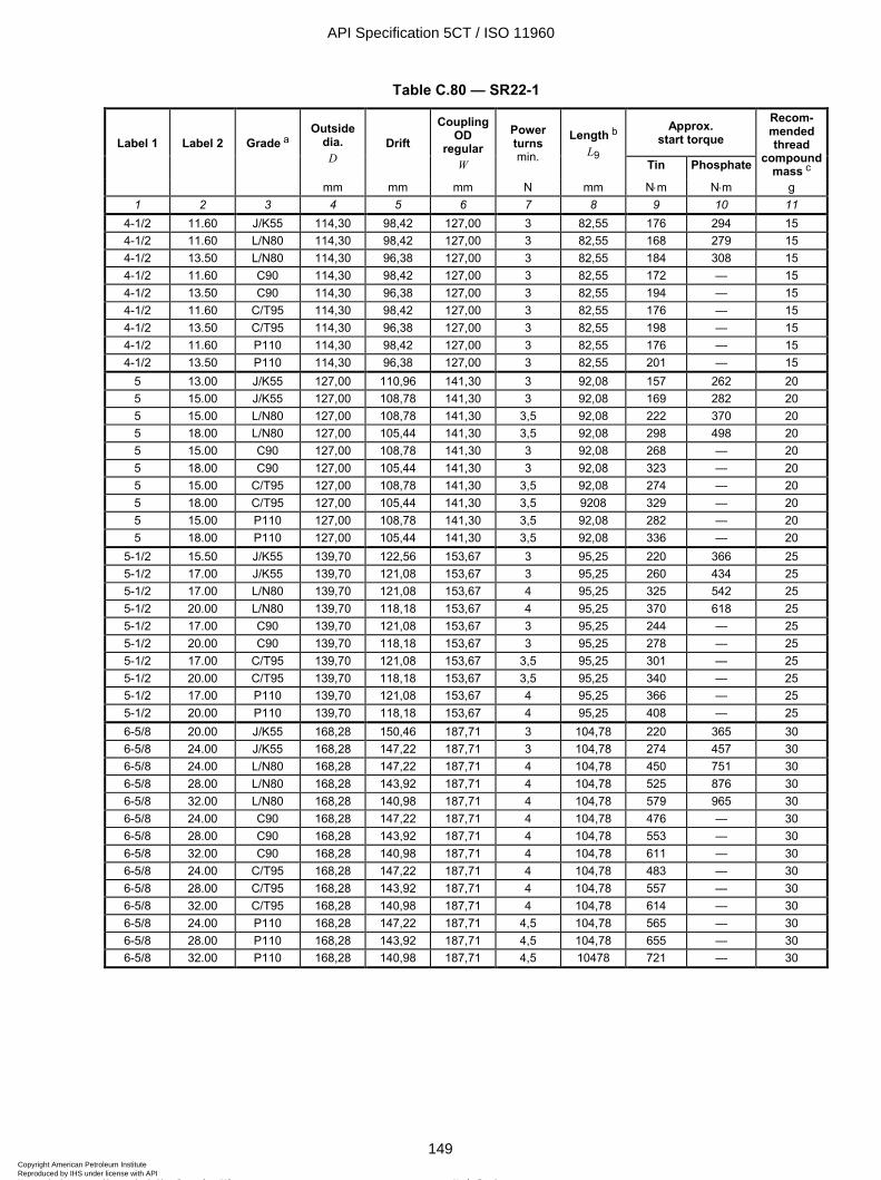
ISO 11960:2004(E)
© ISO 2004 – All rights reserved 149
Table C.80 — SR22-1
Approx. start torque Label 1 Label 2 Grade a
Outside dia.
D Drift
Coupling OD
regular W
Power turns min.
Length b L9
Tin Phosphate
Recom-mended thread
compound mass c
mm mm mm N mm N⋅m N⋅m g 1 2 3 4 5 6 7 8 9 10 11
4-1/2 11.60 J/K55 114,30 98,42 127,00 3 82,55 176 294 15 4-1/2 11.60 L/N80 114,30 98,42 127,00 3 82,55 168 279 15 4-1/2 13.50 L/N80 114,30 96,38 127,00 3 82,55 184 308 15 4-1/2 11.60 C90 114,30 98,42 127,00 3 82,55 172 — 15 4-1/2 13.50 C90 114,30 96,38 127,00 3 82,55 194 — 15 4-1/2 11.60 C/T95 114,30 98,42 127,00 3 82,55 176 — 15 4-1/2 13.50 C/T95 114,30 96,38 127,00 3 82,55 198 — 15 4-1/2 11.60 P110 114,30 98,42 127,00 3 82,55 176 — 15 4-1/2 13.50 P110 114,30 96,38 127,00 3 82,55 201 — 15
5 13.00 J/K55 127,00 110,96 141,30 3 92,08 157 262 20 5 15.00 J/K55 127,00 108,78 141,30 3 92,08 169 282 20 5 15.00 L/N80 127,00 108,78 141,30 3,5 92,08 222 370 20 5 18.00 L/N80 127,00 105,44 141,30 3,5 92,08 298 498 20 5 15.00 C90 127,00 108,78 141,30 3 92,08 268 — 20 5 18.00 C90 127,00 105,44 141,30 3 92,08 323 — 20 5 15.00 C/T95 127,00 108,78 141,30 3,5 92,08 274 — 20 5 18.00 C/T95 127,00 105,44 141,30 3,5 9208 329 — 20 5 15.00 P110 127,00 108,78 141,30 3,5 92,08 282 — 20 5 18.00 P110 127,00 105,44 141,30 3,5 92,08 336 — 20
5-1/2 15.50 J/K55 139,70 122,56 153,67 3 95,25 220 366 25 5-1/2 17.00 J/K55 139,70 121,08 153,67 3 95,25 260 434 25 5-1/2 17.00 L/N80 139,70 121,08 153,67 4 95,25 325 542 25 5-1/2 20.00 L/N80 139,70 118,18 153,67 4 95,25 370 618 25 5-1/2 17.00 C90 139,70 121,08 153,67 3 95,25 244 — 25 5-1/2 20.00 C90 139,70 118,18 153,67 3 95,25 278 — 25 5-1/2 17.00 C/T95 139,70 121,08 153,67 3,5 95,25 301 — 25 5-1/2 20.00 C/T95 139,70 118,18 153,67 3,5 95,25 340 — 25 5-1/2 17.00 P110 139,70 121,08 153,67 4 95,25 366 — 25 5-1/2 20.00 P110 139,70 118,18 153,67 4 95,25 408 — 25 6-5/8 20.00 J/K55 168,28 150,46 187,71 3 104,78 220 365 30 6-5/8 24.00 J/K55 168,28 147,22 187,71 3 104,78 274 457 30 6-5/8 24.00 L/N80 168,28 147,22 187,71 4 104,78 450 751 30 6-5/8 28.00 L/N80 168,28 143,92 187,71 4 104,78 525 876 30 6-5/8 32.00 L/N80 168,28 140,98 187,71 4 104,78 579 965 30 6-5/8 24.00 C90 168,28 147,22 187,71 4 104,78 476 — 30 6-5/8 28.00 C90 168,28 143,92 187,71 4 104,78 553 — 30 6-5/8 32.00 C90 168,28 140,98 187,71 4 104,78 611 — 30 6-5/8 24.00 C/T95 168,28 147,22 187,71 4 104,78 483 — 30 6-5/8 28.00 C/T95 168,28 143,92 187,71 4 104,78 557 — 30 6-5/8 32.00 C/T95 168,28 140,98 187,71 4 104,78 614 — 30 6-5/8 24.00 P110 168,28 147,22 187,71 4,5 104,78 565 — 30 6-5/8 28.00 P110 168,28 143,92 187,71 4,5 104,78 655 — 30 6-5/8 32.00 P110 168,28 140,98 187,71 4,5 10478 721 — 30
API Specification 5CT / ISO 11960
149Copyright American Petroleum Institute Reproduced by IHS under license with API
Not for ResaleNo reproduction or networking permitted without license from IHS
--`,,,```-`-`,,`,,`,`,,`---
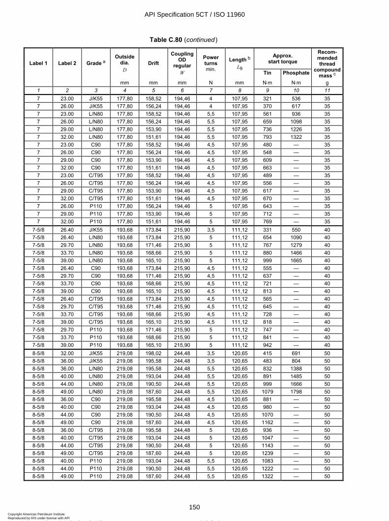
ISO 11960:2004(E)
150 © ISO 2004 – All rights reserved
Table C.80 (continued)
Approx. start torque Label 1 Label 2 Grade a
Outside dia.
D Drift
Coupling OD
regular W
Power turns min.
Length b L9
Tin Phosphate
Recom-mended thread
compound mass c
mm mm mm N mm N⋅m N⋅m g 1 2 3 4 5 6 7 8 9 10 11 7 23.00 J/K55 177,80 158,52 194,46 4 107,95 321 536 35 7 26.00 J/K55 177,80 156,24 194,46 4 107,95 370 617 35 7 23.00 L/N80 177,80 158,52 194,46 5,5 107,95 561 936 35 7 26.00 L/N80 177,80 156,24 194,46 5,5 107,95 659 1098 35 7 29.00 L/N80 177,80 153,90 194,46 5,5 107,95 736 1226 35 7 32.00 L/N80 177,80 151,61 194,46 5,5 107,95 793 1322 35 7 23.00 C90 177,80 158,52 194,46 4,5 107,95 480 — 35 7 26.00 C90 177,80 156,24 194,46 4,5 107,95 548 — 35 7 29.00 C90 177,80 153,90 194,46 4,5 107,95 609 — 35 7 32.00 C90 177,80 151,61 194,46 4,5 107,95 663 — 35 7 23.00 C/T95 177,80 158,52 194,46 4,5 107,95 489 — 35 7 26.00 C/T95 177,80 156,24 194,46 4,5 107,95 556 — 35 7 29.00 C/T95 177,80 153,90 194,46 4,5 107,95 617 — 35 7 32.00 C/T95 177,80 151,61 194,46 4,5 107,95 670 — 35 7 26.00 P110 177,80 156,24 194,46 5 107,95 643 — 35 7 29.00 P110 177,80 153,90 194,46 5 107,95 712 — 35 7 32.00 P110 177,80 151,61 194,46 5 107,95 769 — 35
7-5/8 26.40 J/K55 193,68 173,84 215,90 3,5 111,12 331 550 40 7-5/8 26.40 L/N80 193,68 173,84 215,90 5 111,12 654 1090 40 7-5/8 29.70 L/N80 193,68 171,46 215,90 5 111,12 767 1279 40 7-5/8 33.70 L/N80 193,68 168,66 215,90 5 111,12 880 1466 40 7-5/8 39.00 L/N80 193,68 165,10 215,90 5 111,12 999 1665 40 7-5/8 26.40 C90 193,68 173,84 215,90 4,5 111,12 555 — 40 7-5/8 29.70 C90 193,68 171,46 215,90 4,5 111,12 637 — 40 7-5/8 33.70 C90 193,68 168,66 215,90 4,5 111,12 721 — 40 7-5/8 39.00 C90 193,68 165,10 215,90 4,5 111,12 813 — 40 7-5/8 26.40 C/T95 193,68 173,84 215,90 4,5 111,12 565 — 40 7-5/8 29.70 C/T95 193,68 171,46 215,90 4,5 111,12 645 — 40 7-5/8 33.70 C/T95 193,68 168,66 215,90 4,5 111,12 728 — 40 7-5/8 39.00 C/T95 193,68 165,10 215,90 4,5 111,12 818 — 40 7-5/8 29.70 P110 193,68 171,46 215,90 5 111,12 747 — 40 7-5/8 33.70 P110 193,68 168,66 215,90 5 111,12 841 — 40 7-5/8 39.00 P110 193,68 165,10 215,90 5 111,12 942 — 40 8-5/8 32.00 J/K55 219,08 198,02 244,48 3,5 120,65 415 691 50 8-5/8 36.00 J/K55 219,08 195,58 244,48 3,5 120,65 483 804 50 8-5/8 36.00 L/N80 219,08 195,58 244,48 5,5 120,65 832 1388 50 8-5/8 40.00 L/N80 219,08 193,04 244,48 5,5 120,65 891 1485 50 8-5/8 44.00 L/N80 219,08 190,50 244,48 5,5 120,65 999 1666 50 8-5/8 49.00 L/N80 219,08 187,60 244,48 5,5 120,65 1079 1798 50 8-5/8 36.00 C90 219,08 195,58 244,48 4,5 120,65 881 — 50 8-5/8 40.00 C90 219,08 193,04 244,48 4,5 120,65 980 — 50 8-5/8 44.00 C90 219,08 190,50 244,48 4,5 120,65 1070 — 50 8-5/8 49.00 C90 219,08 187,60 244,48 4,5 120,65 1162 — 50 8-5/8 36.00 C/T95 219,08 195,58 244,48 5 120,65 936 — 50 8-5/8 40.00 C/T95 219,08 193,04 244,48 5 120,65 1047 — 50 8-5/8 44.00 C/T95 219,08 190,50 244,48 5 120,65 1143 — 50 8-5/8 49.00 C/T95 219,08 187,60 244,48 5 120,65 1239 — 50 8-5/8 40.00 P110 219,08 193,04 244,48 5,5 120,65 1083 — 50 8-5/8 44.00 P110 219,08 190,50 244,48 5,5 120,65 1222 — 50 8-5/8 49.00 P110 219,08 187,60 244,48 5,5 120,65 1322 — 50
API Specification 5CT / ISO 11960
150Copyright American Petroleum Institute Reproduced by IHS under license with API
Not for ResaleNo reproduction or networking permitted without license from IHS
--`,,,```-`-`,,`,,`,`,,`---
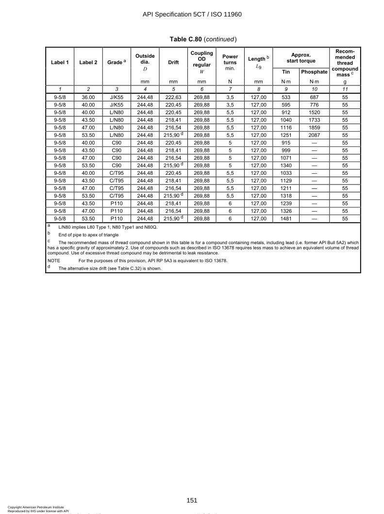
ISO 11960:2004(E)
© ISO 2004 – All rights reserved 151
Table C.80 (continued)
Approx. start torque Label 1 Label 2 Grade a
Outside dia.
D Drift
Coupling OD
regular W
Power turns min.
Length b L9
Tin Phosphate
Recom-mended thread
compound mass c
mm mm mm N mm N⋅m N⋅m g 1 2 3 4 5 6 7 8 9 10 11
9-5/8 36.00 J/K55 244,48 222,63 269,88 3,5 127,00 533 687 55 9-5/8 40.00 J/K55 244,48 220,45 269,88 3,5 127,00 595 776 55 9-5/8 40.00 L/N80 244,48 220,45 269,88 5,5 127,00 912 1520 55 9-5/8 43.50 L/N80 244,48 218,41 269,88 5,5 127,00 1040 1733 55 9-5/8 47.00 L/N80 244,48 216,54 269,88 5,5 127,00 1116 1859 55 9-5/8 53.50 L/N80 244,48 215,90 d 269,88 5,5 127,00 1251 2087 55 9-5/8 40.00 C90 244,48 220,45 269,88 5 127,00 915 — 55 9-5/8 43.50 C90 244,48 218,41 269,88 5 127,00 999 — 55 9-5/8 47.00 C90 244,48 216,54 269,88 5 127,00 1071 — 55 9-5/8 53.50 C90 244,48 215,90 d 269,88 5 127,00 1340 — 55 9-5/8 40.00 C/T95 244,48 220,45 269,88 5,5 127,00 1033 — 55 9-5/8 43.50 C/T95 244,48 218,41 269,88 5,5 127,00 1129 — 55 9-5/8 47.00 C/T95 244,48 216,54 269,88 5,5 127,00 1211 — 55 9-5/8 53.50 C/T95 244,48 215,90 d 269,88 5,5 127,00 1318 — 55 9-5/8 43.50 P110 244,48 218,41 269,88 6 127,00 1239 — 55 9-5/8 47.00 P110 244,48 216,54 269,88 6 127,00 1326 — 55 9-5/8 53.50 P110 244,48 215,90 d 269,88 6 127,00 1481 — 55
a L/N80 implies L80 Type 1, N80 Type1 and N80Q. b End of pipe to apex of triangle c The recommended mass of thread compound shown in this table is for a compound containing metals, including lead (i.e. former API Bull 5A2) which has a specific gravity of approximately 2. Use of compounds such as described in ISO 13678 requires less mass to achieve an equivalent volume of thread compound. Use of excessive thread compound may be detrimental to leak resistance.
NOTE For the purposes of this provision, API RP 5A3 is equivalent to ISO 13678. d The alternative size drift (see Table C.32) is shown.
API Specification 5CT / ISO 11960
151Copyright American Petroleum Institute Reproduced by IHS under license with API
Not for ResaleNo reproduction or networking permitted without license from IHS
--`,,,```-`-`,,`,,`,`,,`---
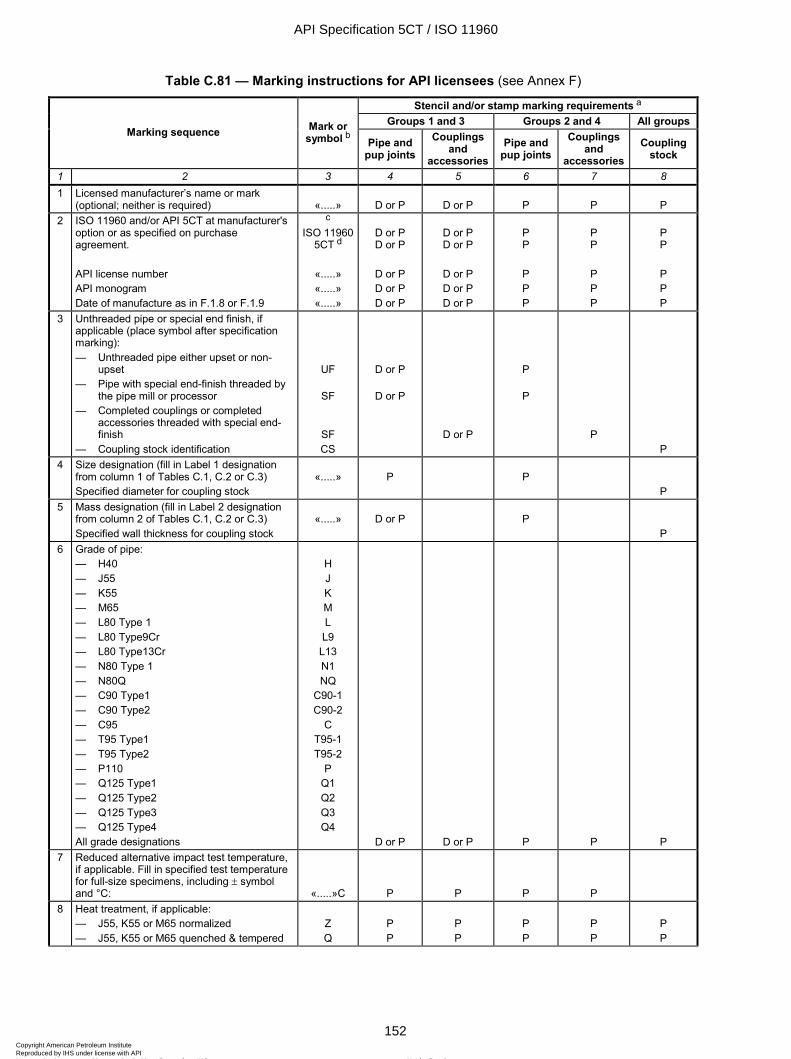
ISO 11960:2004(E)
152 © ISO 2004 – All rights reserved
Table C.81 — Marking instructions for API licensees (see Annex F)
Stencil and/or stamp marking requirements a
Groups 1 and 3 Groups 2 and 4 All groups Marking sequence Mark or
symbol b Pipe and pup joints
Couplings and
accessoriesPipe and
pup joints Couplings
and accessories
Coupling stock
1 2 3 4 5 6 7 8 1 Licensed manufacturer’s name or mark
(optional; neither is required) «.....» D or P D or P P P P 2 ISO 11960 and/or API 5CT at manufacturer's
option or as specified on purchase agreement. API license number API monogram Date of manufacture as in F.1.8 or F.1.9
c ISO 11960
5CT d
«.....» «.....» «.....»
D or P D or P
D or P D or P D or P
D or P D or P
D or P D or P D or P
P P
P P P
P P
P P P
P P
P P P
3 Unthreaded pipe or special end finish, if applicable (place symbol after specification marking): — Unthreaded pipe either upset or non-
upset — Pipe with special end-finish threaded by
the pipe mill or processor — Completed couplings or completed
accessories threaded with special end-finish
— Coupling stock identification
UF
SF
SF CS
D or P
D or P
D or P
P
P
P P
4 Size designation (fill in Label 1 designation from column 1 of Tables C.1, C.2 or C.3) Specified diameter for coupling stock
«.....»
P
P
P 5 Mass designation (fill in Label 2 designation
from column 2 of Tables C.1, C.2 or C.3) Specified wall thickness for coupling stock
«.....»
D or P
P
P 6 Grade of pipe:
— H40 — J55 — K55 — M65 — L80 Type 1 — L80 Type9Cr — L80 Type13Cr — N80 Type 1 — N80Q — C90 Type1 — C90 Type2 — C95 — T95 Type1 — T95 Type2 — P110 — Q125 Type1 — Q125 Type2 — Q125 Type3 — Q125 Type4 All grade designations
H J K M L L9
L13 N1 NQ
C90-1 C90-2
C T95-1 T95-2
P Q1 Q2 Q3 Q4
D or P D or P P P P 7 Reduced alternative impact test temperature,
if applicable. Fill in specified test temperature for full-size specimens, including ± symbol and °C: «.....»C P P P P
8 Heat treatment, if applicable: — J55, K55 or M65 normalized — J55, K55 or M65 quenched & tempered
Z Q
P P
P P
P P
P P
P P
API Specification 5CT / ISO 11960
152Copyright American Petroleum Institute Reproduced by IHS under license with API
Not for ResaleNo reproduction or networking permitted without license from IHS
--`,,,```-`-`,,`,,`,`,,`---

ISO 11960:2004(E)
© ISO 2004 – All rights reserved 153
Table C.81 (continued)
Stencil and/or stamp marking requirements a
Groups 1 and 3 Groups 2 and 4 All groups Marking sequence Mark or
symbol b Pipe and pup joints
Couplings and
accessoriesPipe and
pup joints Couplings
and accessories
Coupling stock
1 2 3 4 5 6 7 8 9 Process of manufacture:
— Seamless — Electric-welded All designations
S E
D or P
P
10 Supplementary requirements, if applicable: — A.2 (SR1) — A.3 (SR2) — A.4 (SR9) (fill in type) — A.8 (SR13) — A.10 (SR16) (fill in minimum full-size
energy absorption requirement in joules and test temperature including ± symbol and °C)
— A.11 (SR22) — Annex H (PSL)
S1 S2
S9Q«.....» S13
S16«.....»C
S22 L2 or L3
P P
P
P P
D or P
D P
P P
P
P P
P P
D P P
11 Hydrostatic test pressure e (fill in the actual test pressure in MPa) All designations P«.....» P
P
12 Type of thread, if applicable: — For manufacturers, processors or
threaders of casing buttress, extreme-line or round threads (fill in type of thread from Table C.67).
— For threaders of tubing threads (fill in type of thread from Table C.67)
«.....»
«.....»
P
P
P
P
13 Full length drift test, if applicable: — Standard (casing or tubing) — Alternative (casing or tubing) where
« ..... » is the size of the alternative drift. — For casing specified for tubing service
and drift-tested in accordance with 8.10 All designations
D
DA« ..... »
DT42 P
P
14 Serialization of Grades C90, T95 and Q125 D f or P D f or P P 15 Tin plating of couplings, if applicable T P P 16 Couplings H40, J55 and K55 only visually
inspected V
P
NOTE See F.4 for mandatory colour code requirements. a D = optional (die) stamping; P = Requirement for (paint) stencilling. Optional marking is permitted as specified in F.1 and F.2. b A blank space, «.....», indicates information to be filled in. c The manufacturer may include “API” before “5CT”. d Alternative markings for the standards are: “5CT”, “API 5CT”, “ISO 11960 5CT”. e Pipe can be identified as manufactured to SI units by the marked hydro-test pressure which will be less than 100 (MPa), while the pressure marked for pipe manufactured to USC units (psi) will be over 1 000. This information is used to clearly identify the units used for CVN markings, which shall be in the same unit system as the pressure markings. f Stamp marking shall conform to the requirements of F.2.5.
API Specification 5CT / ISO 11960
153Copyright American Petroleum Institute Reproduced by IHS under license with API
Not for ResaleNo reproduction or networking permitted without license from IHS
--`,,,```-`-`,,`,,`,`,,`---
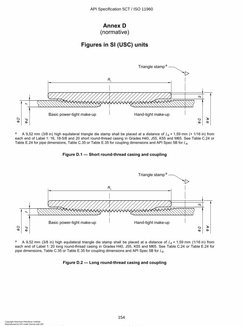
ISO 11960:2004(E)
154 © ISO 2004 – All rights reserved
Annex D (normative)
Figures in SI (USC) units
a A 9,52 mm (3/8 in) high equilateral triangle die stamp shall be placed at a distance of L4 + 1,59 mm (+ 1/16 in) from each end of Label 1: 16, 18-5/8 and 20 short round-thread casing in Grades H40, J55, K55 and M65. See Table C.24 or Table E.24 for pipe dimensions, Table C.35 or Table E.35 for coupling dimensions and API Spec 5B for L4.
Figure D.1 — Short round-thread casing and coupling
a A 9,52 mm (3/8 in) high equilateral triangle die stamp shall be placed at a distance of L4 + 1,59 mm (1/16 in) from each end of Label 1: 20 long round-thread casing in Grades H40, J55, K55 and M65. See Table C.24 or Table E.24 for pipe dimensions, Table C.35 or Table E.35 for coupling dimensions and API Spec 5B for L4.
Figure D.2 — Long round-thread casing and coupling
API Specification 5CT / ISO 11960
154Copyright American Petroleum Institute Reproduced by IHS under license with API
Not for ResaleNo reproduction or networking permitted without license from IHS
--`,,,```-`-`,,`,,`,`,,`---
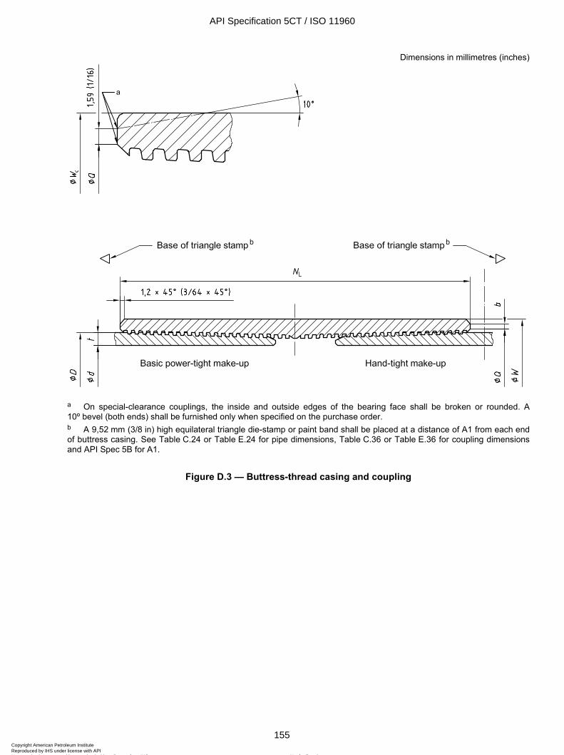
ISO 11960:2004(E)
© ISO 2004 – All rights reserved 155
Dimensions in millimetres (inches)
a On special-clearance couplings, the inside and outside edges of the bearing face shall be broken or rounded. A 10º bevel (both ends) shall be furnished only when specified on the purchase order. b A 9,52 mm (3/8 in) high equilateral triangle die-stamp or paint band shall be placed at a distance of A1 from each end of buttress casing. See Table C.24 or Table E.24 for pipe dimensions, Table C.36 or Table E.36 for coupling dimensions and API Spec 5B for A1.
Figure D.3 — Buttress-thread casing and coupling
API Specification 5CT / ISO 11960
155Copyright American Petroleum Institute Reproduced by IHS under license with API
Not for ResaleNo reproduction or networking permitted without license from IHS
--`,,,```-`-`,,`,,`,`,,`---
ISO 11960:2004(E)
156 © ISO 2004 – All rights reserved
NOTE See Table C.25 or Table E.25 for pipe dimensions, Table C.37 or Table E.37 for coupling dimensions and API Spec 5B for thread details.
a On special bevel couplings, the inside and outside edges of the bearing face shall be broken or rounded.
Figure D.4 — Non-upset tubing and coupling
API Specification 5CT / ISO 11960
156Copyright American Petroleum Institute Reproduced by IHS under license with API
Not for ResaleNo reproduction or networking permitted without license from IHS
--`,,,```-`-`,,`,,`,`,,`---
ISO 11960:2004(E)
© ISO 2004 – All rights reserved 157
NOTE See Tables C.25 and C.27 or Tables E.25 and E.27 for pipe dimensions, Table C.38 or Table E.38 for coupling dimensions and API Spec 5B for thread details.
a On special bevel couplings and special clearance couplings, the inside and outside edges of the bearing face shall be broken or rounded. b Upset run-out interval, not to be confused with b on the right-hand side of the figure which indicates the coupling bearing face dimension. c See 8.11.1 for tolerance on outside diameter at a distance La from end of pipe.
Figure D.5 — External-upset tubing and coupling
API Specification 5CT / ISO 11960
157Copyright American Petroleum Institute Reproduced by IHS under license with API
Not for ResaleNo reproduction or networking permitted without license from IHS
--`,,,```-`-`,,`,,`,`,,`---
ISO 11960:2004(E)
158 © ISO 2004 – All rights reserved
Label 1 Radius a
r mm (in)
1 2 2-3/8 2,4 (3/32) 2-7/8 2,4 (3/32) 3-1/2 3,2 (1/8) 4-1/2 3,2 (1/8)
a These dimensions are for reference only and are not subject to measurement for determining product acceptance.
NOTE See API Spec 5B for product acceptance.
Figure D.6 — Rounded nose for external-upset tubing
NOTE 1 Dashed lines indicate power-tight make-up.
NOTE 2 See Tables C.25 and C.28 or Tables E.25 and E.28 for pipe dimensions and API Spec 5B for thread details.
Figure D.7 — Integral-joint tubing
API Specification 5CT / ISO 11960
158Copyright American Petroleum Institute Reproduced by IHS under license with API
Not for ResaleNo reproduction or networking permitted without license from IHS
--`,,,```-`-`,,`,,`,`,,`---
ISO 11960:2004(E)
© ISO 2004 – All rights reserved 159
Dimensions in millimetres (inches)
Key 1 box 2 pin
a For 193,70 (7-5/8) outside diameter and smaller. b For 219,10 (8-5/8) outside diameter and larger. c Upset run-out interval, including both internal and external upset tapers. d Drift diameter.
Figure D.8 — Extreme-line casing
API Specification 5CT / ISO 11960
159Copyright American Petroleum Institute Reproduced by IHS under license with API
Not for ResaleNo reproduction or networking permitted without license from IHS
--`,,,```-`-`,,`,,`,`,,`---
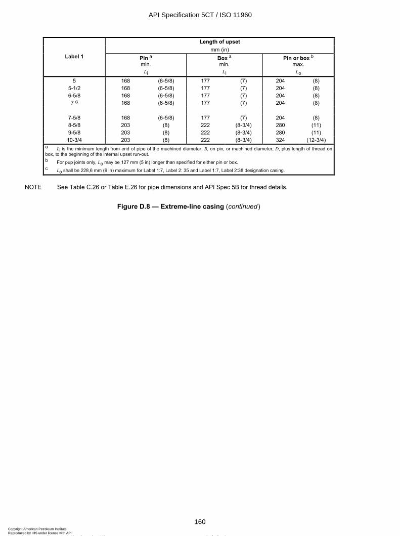
ISO 11960:2004(E)
160 © ISO 2004 – All rights reserved
Length of upset mm (in)
Label 1 Pin a min.
Li
Box a min.
Li
Pin or box b max.
Lo 5 168 (6-5/8) 177 (7) 204 (8)
5-1/2 168 (6-5/8) 177 (7) 204 (8) 6-5/8 168 (6-5/8) 177 (7) 204 (8) 7 c 168 (6-5/8) 177 (7) 204 (8)
7-5/8 168 (6-5/8) 177 (7) 204 (8) 8-5/8 203 (8) 222 (8-3/4) 280 (11) 9-5/8 203 (8) 222 (8-3/4) 280 (11)
10-3/4 203 (8) 222 (8-3/4) 324 (12-3/4) a Li is the minimum length from end of pipe of the machined diameter, B, on pin, or machined diameter, D, plus length of thread on box, to the beginning of the internal upset run-out. b For pup joints only, Lo may be 127 mm (5 in) longer than specified for either pin or box. c Lo shall be 228,6 mm (9 in) maximum for Label 1:7, Label 2: 35 and Label 1:7, Label 2:38 designation casing.
NOTE See Table C.26 or Table E.26 for pipe dimensions and API Spec 5B for thread details.
Figure D.8 — Extreme-line casing (continued)
API Specification 5CT / ISO 11960
160Copyright American Petroleum Institute Reproduced by IHS under license with API
Not for ResaleNo reproduction or networking permitted without license from IHS
--`,,,```-`-`,,`,,`,`,,`---
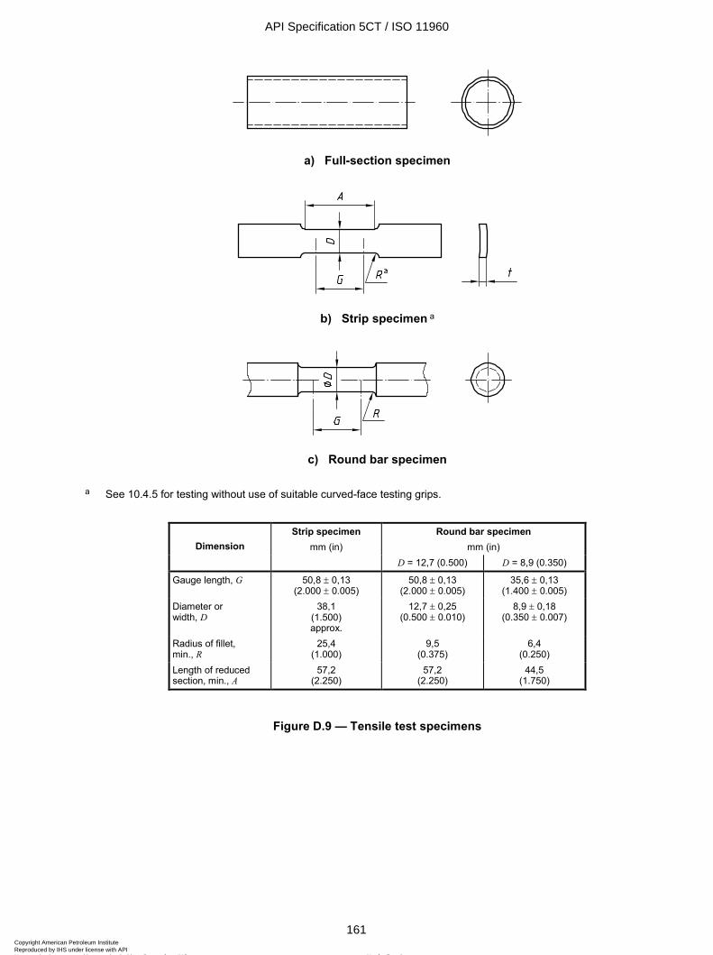
ISO 11960:2004(E)
© ISO 2004 – All rights reserved 161
a) Full-section specimen
b) Strip specimen a
c) Round bar specimen
a See 10.4.5 for testing without use of suitable curved-face testing grips.
Strip specimen Round bar specimen mm (in) Dimension mm (in)
D = 12,7 (0.500) D = 8,9 (0.350)
Gauge length, G 50,8 ± 0,13 (2.000 ± 0.005)
50,8 ± 0,13 (2.000 ± 0.005)
35,6 ± 0,13 (1.400 ± 0.005)
Diameter or width, D
38,1 (1.500) approx.
12,7 ± 0,25 (0.500 ± 0.010)
8,9 ± 0,18 (0.350 ± 0.007)
Radius of fillet, min., R
25,4 (1.000)
9,5 (0.375)
6,4 (0.250)
Length of reduced section, min., A
57,2 (2.250)
57,2 (2.250)
44,5 (1.750)
Figure D.9 — Tensile test specimens
API Specification 5CT / ISO 11960
161Copyright American Petroleum Institute Reproduced by IHS under license with API
Not for ResaleNo reproduction or networking permitted without license from IHS
--`,,,```-`-`,,`,,`,`,,`---
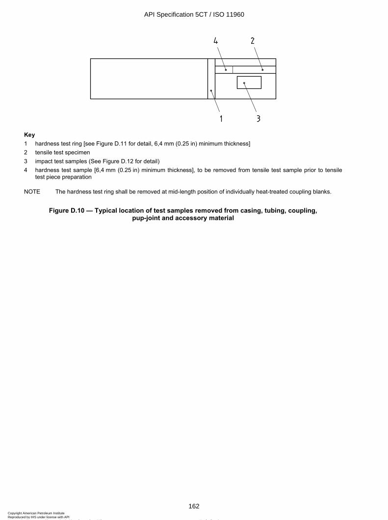
ISO 11960:2004(E)
162 © ISO 2004 – All rights reserved
Key 1 hardness test ring [see Figure D.11 for detail, 6,4 mm (0.25 in) minimum thickness] 2 tensile test specimen 3 impact test samples (See Figure D.12 for detail) 4 hardness test sample [6,4 mm (0.25 in) minimum thickness], to be removed from tensile test sample prior to tensile
test piece preparation
NOTE The hardness test ring shall be removed at mid-length position of individually heat-treated coupling blanks.
Figure D.10 — Typical location of test samples removed from casing, tubing, coupling, pup-joint and accessory material
API Specification 5CT / ISO 11960
162Copyright American Petroleum Institute Reproduced by IHS under license with API
Not for ResaleNo reproduction or networking permitted without license from IHS
--`,,,```-`-`,,`,,`,`,,`---
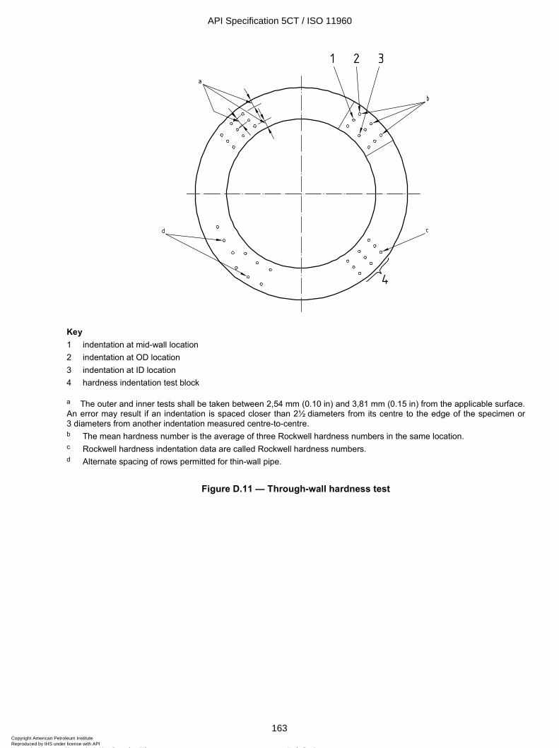
ISO 11960:2004(E)
© ISO 2004 – All rights reserved 163
Key 1 indentation at mid-wall location 2 indentation at OD location 3 indentation at ID location 4 hardness indentation test block
a The outer and inner tests shall be taken between 2,54 mm (0.10 in) and 3,81 mm (0.15 in) from the applicable surface. An error may result if an indentation is spaced closer than 2½ diameters from its centre to the edge of the specimen or 3 diameters from another indentation measured centre-to-centre. b The mean hardness number is the average of three Rockwell hardness numbers in the same location. c Rockwell hardness indentation data are called Rockwell hardness numbers. d Alternate spacing of rows permitted for thin-wall pipe.
Figure D.11 — Through-wall hardness test
API Specification 5CT / ISO 11960
163Copyright American Petroleum Institute Reproduced by IHS under license with API
Not for ResaleNo reproduction or networking permitted without license from IHS
--`,,,```-`-`,,`,,`,`,,`---
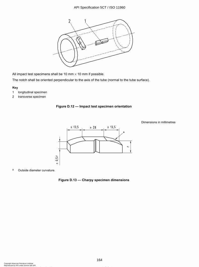
ISO 11960:2004(E)
164 © ISO 2004 – All rights reserved
All impact test specimens shall be 10 mm ¥ 10 mm if possible.
The notch shall be oriented perpendicular to the axis of the tube (normal to the tube surface).
Key 1 longitudinal specimen 2 transverse specimen
Figure D.12 — Impact test specimen orientation
Dimensions in millimetres
a Outside diameter curvature.
Figure D.13 — Charpy specimen dimensions
API Specification 5CT / ISO 11960
164Copyright American Petroleum Institute Reproduced by IHS under license with API
Not for ResaleNo reproduction or networking permitted without license from IHS
--`,,,```-`-`,,`,,`,`,,`---
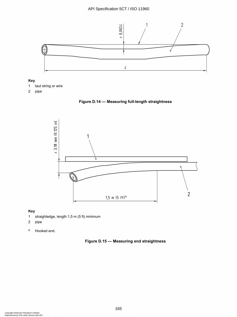
ISO 11960:2004(E)
© ISO 2004 – All rights reserved 165
Key 1 taut string or wire 2 pipe
Figure D.14 — Measuring full-length straightness
Key 1 straightedge, length 1,5 m (5 ft) minimum 2 pipe
a Hooked end.
Figure D.15 — Measuring end straightness
API Specification 5CT / ISO 11960
165Copyright American Petroleum Institute Reproduced by IHS under license with API
Not for ResaleNo reproduction or networking permitted without license from IHS
--`,,,```-`-`,,`,,`,`,,`---
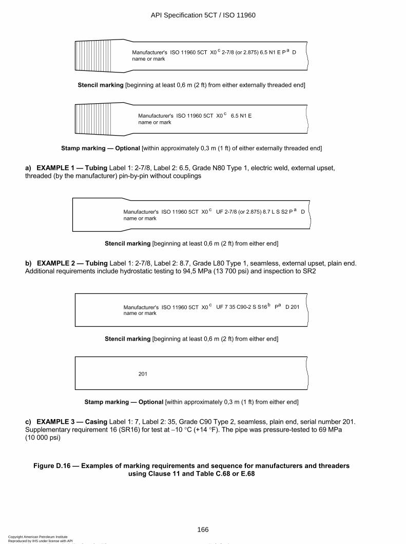
ISO 11960:2004(E)
166 © ISO 2004 – All rights reserved
Stencil marking [beginning at least 0,6 m (2 ft) from either externally threaded end]
Stamp marking — Optional [within approximately 0,3 m (1 ft) of either externally threaded end]
a) EXAMPLE 1 — Tubing Label 1: 2-7/8, Label 2: 6.5, Grade N80 Type 1, electric weld, external upset, threaded (by the manufacturer) pin-by-pin without couplings
Stencil marking [beginning at least 0,6 m (2 ft) from either end]
b) EXAMPLE 2 — Tubing Label 1: 2-7/8, Label 2: 8.7, Grade L80 Type 1, seamless, external upset, plain end. Additional requirements include hydrostatic testing to 94,5 MPa (13 700 psi) and inspection to SR2
Stencil marking [beginning at least 0,6 m (2 ft) from either end]
Stamp marking — Optional [within approximately 0,3 m (1 ft) from either end]
c) EXAMPLE 3 — Casing Label 1: 7, Label 2: 35, Grade C90 Type 2, seamless, plain end, serial number 201. Supplementary requirement 16 (SR16) for test at -10 ∞C (+14 ∞F). The pipe was pressure-tested to 69 MPa (10 000 psi)
Figure D.16 — Examples of marking requirements and sequence for manufacturers and threaders using Clause 11 and Table C.68 or E.68
API Specification 5CT / ISO 11960
166Copyright American Petroleum Institute Reproduced by IHS under license with API
Not for ResaleNo reproduction or networking permitted without license from IHS
--`,,,```-`-`,,`,,`,`,,`---
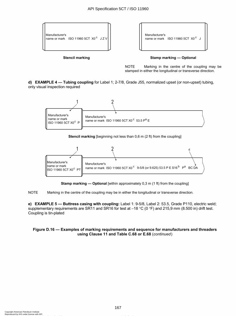
ISO 11960:2004(E)
© ISO 2004 – All rights reserved 167
Stencil marking Stamp marking — Optional
NOTE Marking in the centre of the coupling may be stamped in either the longitudinal or transverse direction.
d) EXAMPLE 4 — Tubing coupling for Label 1; 2-7/8, Grade J55, normalized upset (or non-upset) tubing, only visual inspection required
Stencil marking [beginning not less than 0,6 m (2 ft) from the coupling]
Stamp marking — Optional [within approximately 0,3 m (1 ft) from the coupling]
NOTE Marking in the centre of the coupling may be in either the longitudinal or transverse direction.
e) EXAMPLE 5 — Buttress casing with coupling: Label 1: 9-5/8, Label 2: 53.5, Grade P110, electric weld; supplementary requirements are SR11 and SR16 for test at -18 ∞C (0 ∞F) and 215,9 mm (8.500 in) drift test. Coupling is tin-plated
Figure D.16 — Examples of marking requirements and sequence for manufacturers and threaders using Clause 11 and Table C.68 or E.68 (continued)
API Specification 5CT / ISO 11960
167Copyright American Petroleum Institute Reproduced by IHS under license with API
Not for ResaleNo reproduction or networking permitted without license from IHS
--`,,,```-`-`,,`,,`,`,,`---
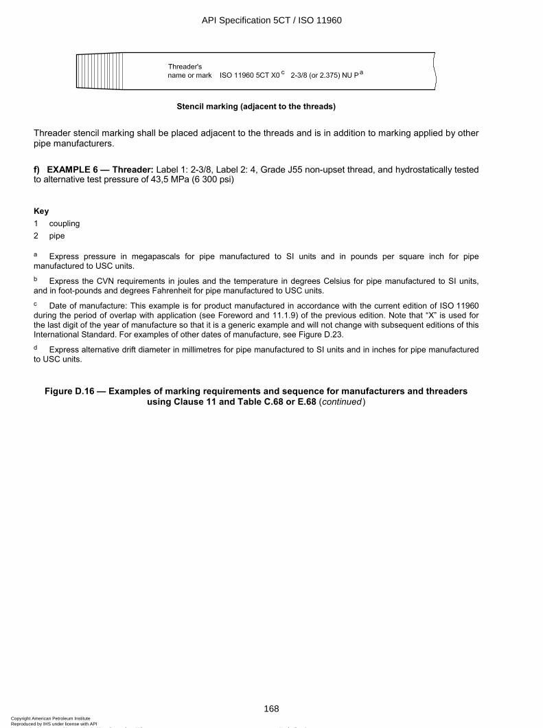
ISO 11960:2004(E)
168 © ISO 2004 – All rights reserved
Stencil marking (adjacent to the threads)
Threader stencil marking shall be placed adjacent to the threads and is in addition to marking applied by other pipe manufacturers.
f) EXAMPLE 6 — Threader: Label 1: 2-3/8, Label 2: 4, Grade J55 non-upset thread, and hydrostatically tested to alternative test pressure of 43,5 MPa (6 300 psi)
Key 1 coupling 2 pipe
a Express pressure in megapascals for pipe manufactured to SI units and in pounds per square inch for pipe manufactured to USC units. b Express the CVN requirements in joules and the temperature in degrees Celsius for pipe manufactured to SI units, and in foot-pounds and degrees Fahrenheit for pipe manufactured to USC units. c Date of manufacture: This example is for product manufactured in accordance with the current edition of ISO 11960 during the period of overlap with application (see Foreword and 11.1.9) of the previous edition. Note that “X” is used for the last digit of the year of manufacture so that it is a generic example and will not change with subsequent editions of this International Standard. For examples of other dates of manufacture, see Figure D.23. d Express alternative drift diameter in millimetres for pipe manufactured to SI units and in inches for pipe manufactured to USC units.
Figure D.16 — Examples of marking requirements and sequence for manufacturers and threaders using Clause 11 and Table C.68 or E.68 (continued)
API Specification 5CT / ISO 11960
168Copyright American Petroleum Institute Reproduced by IHS under license with API
Not for ResaleNo reproduction or networking permitted without license from IHS
--`,,,```-`-`,,`,,`,`,,`---
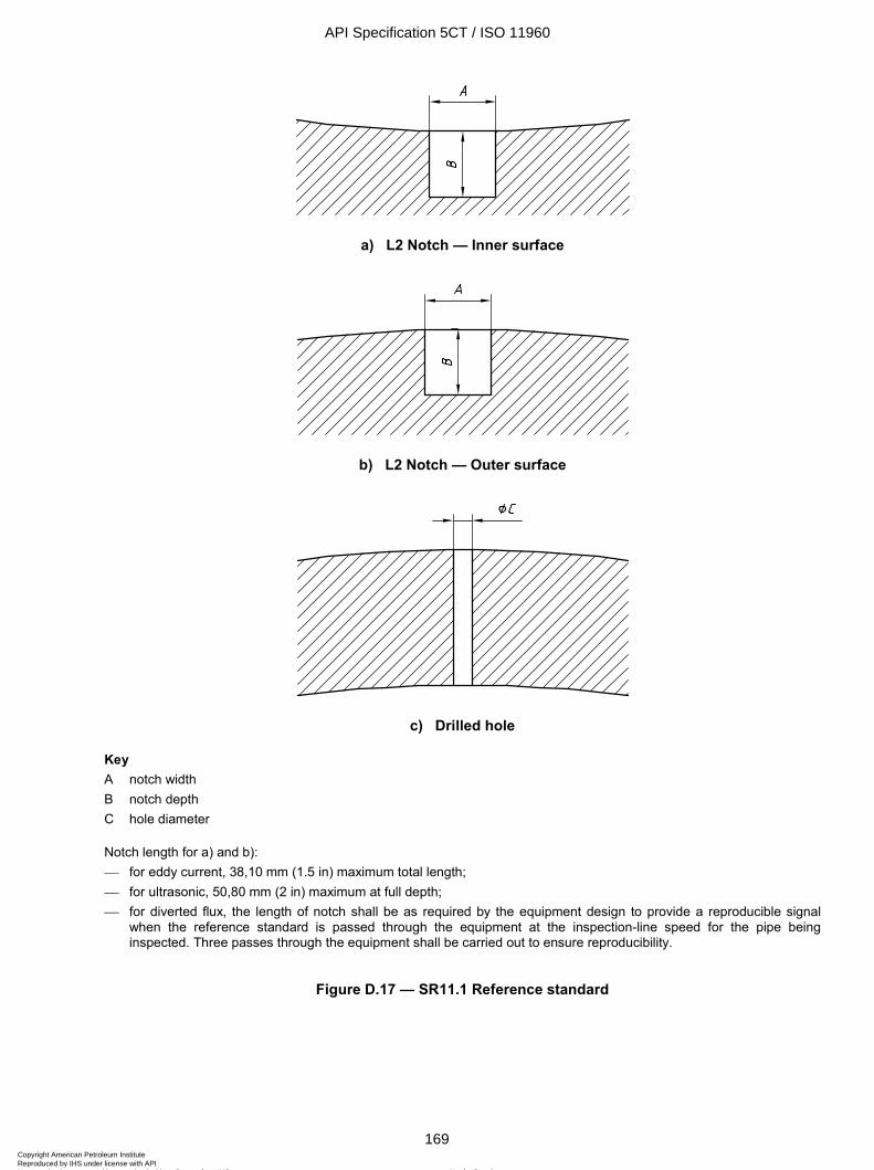
ISO 11960:2004(E)
© ISO 2004 – All rights reserved 169
a) L2 Notch — Inner surface
b) L2 Notch — Outer surface
c) Drilled hole
Key A notch width B notch depth C hole diameter
Notch length for a) and b): for eddy current, 38,10 mm (1.5 in) maximum total length; for ultrasonic, 50,80 mm (2 in) maximum at full depth; for diverted flux, the length of notch shall be as required by the equipment design to provide a reproducible signal
when the reference standard is passed through the equipment at the inspection-line speed for the pipe being inspected. Three passes through the equipment shall be carried out to ensure reproducibility.
Figure D.17 — SR11.1 Reference standard
API Specification 5CT / ISO 11960
169Copyright American Petroleum Institute Reproduced by IHS under license with API
Not for ResaleNo reproduction or networking permitted without license from IHS
--`,,,```-`-`,,`,,`,`,,`---
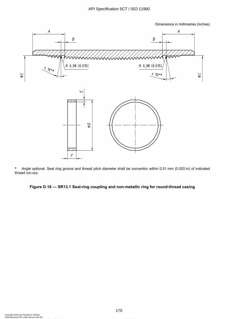
ISO 11960:2004(E)
170 © ISO 2004 – All rights reserved
Dimensions in millimetres (inches)
a Angle optional. Seal ring groove and thread pitch diameter shall be concentric within 0,51 mm (0.020 in) of indicated thread run-out.
Figure D.18 — SR13.1 Seal-ring coupling and non-metallic ring for round-thread casing
API Specification 5CT / ISO 11960
170Copyright American Petroleum Institute Reproduced by IHS under license with API
Not for ResaleNo reproduction or networking permitted without license from IHS
--`,,,```-`-`,,`,,`,`,,`---
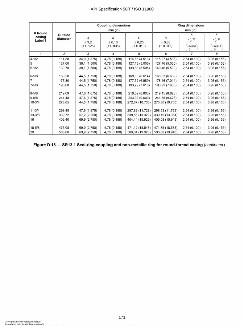
ISO 11960:2004(E)
© ISO 2004 – All rights reserved 171
Coupling dimensions Ring dimensions mm (in) mm (in)
8 Round casing Label 1
Outside diameter A
± 3,2 (± 0.125)
B ± 0,13
(± 0.005)
C ± 0,25
(± 0.010)
D ± 0,38
(± 0.015)
E 0, 250
+
0.0100
+
F 0, 380
+
0.0150
+
1 2 3 4 5 6 7 8 4-1/2 114,30 34,9 (1.375) 4,78 (0.188) 114,63 (4.513) 115,27 (4.538) 2,54 (0.100) 3,96 (0.156) 5 127,00 38,1 (1.500) 4,78 (0.188) 127,13 (5.005) 127,76 (5.030) 2,54 (0.100) 3,96 (0.156) 5-1/2 139,70 38,1 (1.500) 4,78 (0.188) 139,83 (5.505) 140,46 (5.530) 2,54 (0.100) 3,96 (0.156) 6-5/8 168,28 44,5 (1.750) 4,78 (0.188) 168,00 (6.614) 168,63 (6.639) 2,54 (0.100) 3,96 (0.156) 7 177,80 44,5 (1.750) 4,78 (0.188) 177,52 (6.989) 178,16 (7.014) 2,54 (0.100) 3,96 (0.156) 7-5/8 193,68 44,5 (1.750) 4,78 (0.188) 193,29 (7.610) 193,93 (7.635) 2,54 (0.100) 3,96 (0.156) 8-5/8 219,09 47,6 (1.875) 4,78 (0.188) 218,52 (8.603) 219,15 (8.628) 2,54 (0.100) 3,96 (0.156) 9-5/8 244,48 47,6 (1.875) 4,78 (0.188) 243,92 (9.603) 244,55 (9.628) 2,54 (0.100) 3,96 (0.156) 10-3/4 273,05 44,5 (1.750) 4,78 (0.188) 272,67 (10.735) 273,30 (10.760) 2,54 (0.100) 3,96 (0.156) 11-3/4 298,45 47,6 (1.875) 4,78 (0.188) 297,89 (11.728) 298,53 (11.753) 2,54 (0.100) 3,96 (0.156) 13-3/8 339,72 57,2 (2.250) 4,78 (0.188) 338,56 (13.329) 339,19 (13.354) 2,54 (0.100) 3,96 (0.156) 16 406,40 69,9 (2.750) 4,78 (0.188) 404,44 (15.923) 405,08 (15.948) 2,54 (0.100) 3,96 (0.156) 18-5/8 473,08 69,9 (2.750) 4,78 (0.188) 471,12 (18.548) 471,75 (18.573) 2,54 (0.100) 3,96 (0.156) 20 508,00 69,9 (2.750) 4,78 (0.188) 506,04 (19.923) 506,68 (19.948) 2,54 (0.100) 3,96 (0.156)
Figure D.18 — SR13.1 Seal-ring coupling and non-metallic ring for round-thread casing (continued)
API Specification 5CT / ISO 11960
171Copyright American Petroleum Institute Reproduced by IHS under license with API
Not for ResaleNo reproduction or networking permitted without license from IHS
--`,,,```-`-`,,`,,`,`,,`---
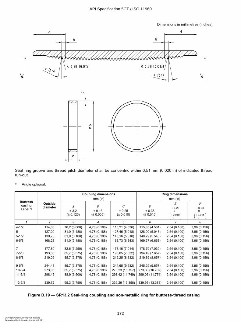
ISO 11960:2004(E)
172 © ISO 2004 – All rights reserved
Dimensions in millimetres (inches)
Seal ring groove and thread pitch diameter shall be concentric within 0,51 mm (0.020 in) of indicated thread run-out.
a Angle optional.
Coupling dimensions Ring dimensions mm (in) mm (in)
Buttress casing Label 1
Outside diameter A
± 3,2 (± 0.125)
B ± 0,13
(± 0.005)
C ± 0,25
(± 0.010)
D ± 0,38
(± 0.015)
E 0, 250
+
0.0100
+
F 0, 380
+
0.0150
+
1 2 3 4 5 6 7 8 4-1/2 114,30 76,2 (3.000) 4,78 (0.188) 115,21 (4.536) 115,85 (4.561) 2,54 (0.100) 3,96 (0.156) 5 127,00 81,0 (3.188) 4,78 (0.188) 127,46 (5.018) 128,09 (5.043) 2,54 (0.100) 3,96 (0.156) 5-1/2 139,70 81,0 (3.188) 4,78 (0.188) 140,16 (5.518) 140,79 (5.543) 2,54 (0.100) 3,96 (0.156) 6-5/8 168,28 81,0 (3.188) 4,78 (0.188) 168,73 (6.643) 169,37 (6.668) 2,54 (0.100) 3,96 (0.156) 7 177,80 82,6 (3.250) 4,78 (0.188) 178,16 (7.014) 178,79 (7.039) 2,54 (0.100) 3,96 (0.156) 7-5/8 193,68 85,7 (3.375) 4,78 (0.188) 193,85 (7.632) 194,49 (7.657) 2,54 (0.100) 3,96 (0.156) 8-5/8 219,09 85,7 (3.375) 4,78 (0.188) 219,25 (8.632) 219,89 (8.657) 2,54 (0.100) 3,96 (0.156) 9-5/8 244,48 85,7 (3.375) 4,78 (0.188) 244,65 (9.632) 245,29 (9.657) 2,54 (0.100) 3,96 (0.156) 10-3/4 273,05 85,7 (3.375) 4,78 (0.188) 273,23 (10.757) 273,86 (10.782) 2,54 (0.100) 3,96 (0.156) 11-3/4 298,45 88,9 (3.500) 4,78 (0.188) 298,42 (11.749) 299,06 (11.774) 2,54 (0.100) 3,96 (0.156) 13-3/8 339,72 95,3 (3.750) 4,78 (0.188) 339,29 (13.358) 339,93 (13.383) 2,54 (0.100) 3,96 (0.156)
Figure D.19 — SR13.2 Seal-ring coupling and non-metallic ring for buttress-thread casing
API Specification 5CT / ISO 11960
172Copyright American Petroleum Institute Reproduced by IHS under license with API
Not for ResaleNo reproduction or networking permitted without license from IHS
--`,,,```-`-`,,`,,`,`,,`---
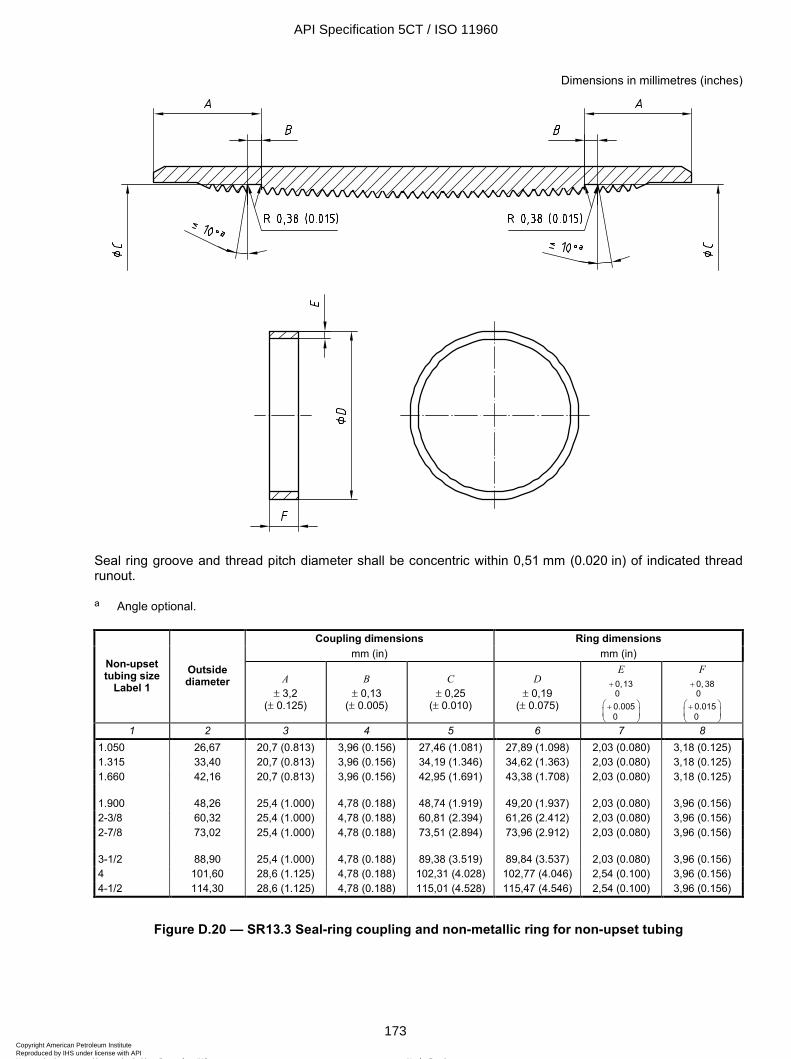
ISO 11960:2004(E)
© ISO 2004 – All rights reserved 173
Dimensions in millimetres (inches)
Seal ring groove and thread pitch diameter shall be concentric within 0,51 mm (0.020 in) of indicated thread runout.
a Angle optional.
Coupling dimensions Ring dimensions mm (in) mm (in)
Non-upset tubing size
Label 1 Outside diameter A
± 3,2 (± 0.125)
B ± 0,13
(± 0.005)
C ± 0,25
(± 0.010)
D ± 0,19
(± 0.075)
E 0,130
+
0.0050
+
F 0, 380
+
0.0150
+
1 2 3 4 5 6 7 8 1.050 26,67 20,7 (0.813) 3,96 (0.156) 27,46 (1.081) 27,89 (1.098) 2,03 (0.080) 3,18 (0.125) 1.315 33,40 20,7 (0.813) 3,96 (0.156) 34,19 (1.346) 34,62 (1.363) 2,03 (0.080) 3,18 (0.125) 1.660 42,16 20,7 (0.813) 3,96 (0.156) 42,95 (1.691) 43,38 (1.708) 2,03 (0.080) 3,18 (0.125) 1.900 48,26 25,4 (1.000) 4,78 (0.188) 48,74 (1.919) 49,20 (1.937) 2,03 (0.080) 3,96 (0.156) 2-3/8 60,32 25,4 (1.000) 4,78 (0.188) 60,81 (2.394) 61,26 (2.412) 2,03 (0.080) 3,96 (0.156) 2-7/8 73,02 25,4 (1.000) 4,78 (0.188) 73,51 (2.894) 73,96 (2.912) 2,03 (0.080) 3,96 (0.156) 3-1/2 88,90 25,4 (1.000) 4,78 (0.188) 89,38 (3.519) 89,84 (3.537) 2,03 (0.080) 3,96 (0.156) 4 101,60 28,6 (1.125) 4,78 (0.188) 102,31 (4.028) 102,77 (4.046) 2,54 (0.100) 3,96 (0.156) 4-1/2 114,30 28,6 (1.125) 4,78 (0.188) 115,01 (4.528) 115,47 (4.546) 2,54 (0.100) 3,96 (0.156)
Figure D.20 — SR13.3 Seal-ring coupling and non-metallic ring for non-upset tubing
API Specification 5CT / ISO 11960
173Copyright American Petroleum Institute Reproduced by IHS under license with API
Not for ResaleNo reproduction or networking permitted without license from IHS
--`,,,```-`-`,,`,,`,`,,`---
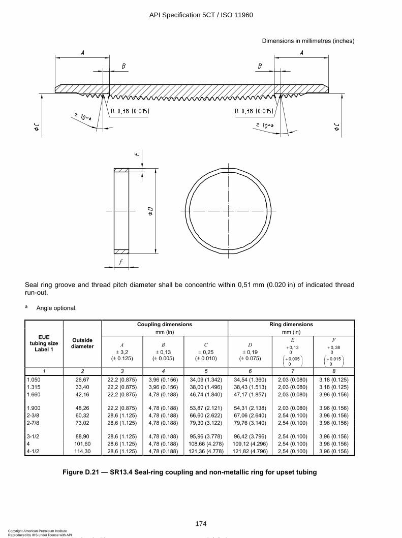
ISO 11960:2004(E)
174 © ISO 2004 – All rights reserved
Dimensions in millimetres (inches)
Seal ring groove and thread pitch diameter shall be concentric within 0,51 mm (0.020 in) of indicated thread run-out.
a Angle optional.
Coupling dimensions Ring dimensions mm (in) mm (in)
EUE tubing size
Label 1 Outside diameter A
± 3,2 (± 0.125)
B ± 0,13
(± 0.005)
C ± 0,25
(± 0.010)
D ± 0,19
(± 0.075)
E 0,130
+
0.0050
+
F 0, 380
+
0.0150
+
1 2 3 4 5 6 7 8 1.050 26,67 22,2 (0.875) 3,96 (0.156) 34,09 (1.342) 34,54 (1.360) 2,03 (0.080) 3,18 (0.125) 1.315 33,40 22,2 (0.875) 3,96 (0.156) 38,00 (1.496) 38,43 (1.513) 2,03 (0.080) 3,18 (0.125) 1.660 42,16 22,2 (0.875) 4,78 (0.188) 46,74 (1.840) 47,17 (1.857) 2,03 (0.080) 3,96 (0.156) 1.900 48,26 22,2 (0.875) 4,78 (0.188) 53,87 (2.121) 54,31 (2.138) 2,03 (0.080) 3,96 (0.156) 2-3/8 60,32 28,6 (1.125) 4,78 (0.188) 66,60 (2.622) 67,06 (2.640) 2,54 (0.100) 3,96 (0.156) 2-7/8 73,02 28,6 (1.125) 4,78 (0.188) 79,30 (3.122) 79,76 (3.140) 2,54 (0.100) 3,96 (0.156) 3-1/2 88,90 28,6 (1.125) 4,78 (0.188) 95,96 (3.778) 96,42 (3.796) 2,54 (0.100) 3,96 (0.156) 4 101,60 28,6 (1.125) 4,78 (0.188) 108,66 (4.278) 109,12 (4.296) 2,54 (0.100) 3,96 (0.156) 4-1/2 114,30 28,6 (1.125) 4,78 (0.188) 121,36 (4.778) 121,82 (4.796) 2,54 (0.100) 3,96 (0.156)
Figure D.21 — SR13.4 Seal-ring coupling and non-metallic ring for upset tubing
API Specification 5CT / ISO 11960
174Copyright American Petroleum Institute Reproduced by IHS under license with API
Not for ResaleNo reproduction or networking permitted without license from IHS
--`,,,```-`-`,,`,,`,`,,`---
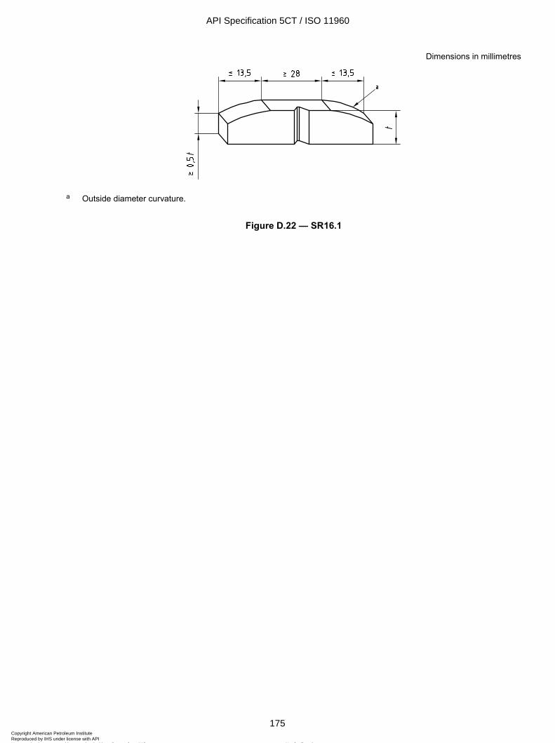
ISO 11960:2004(E)
© ISO 2004 – All rights reserved 175
Dimensions in millimetres
a Outside diameter curvature.
Figure D.22 — SR16.1
API Specification 5CT / ISO 11960
175Copyright American Petroleum Institute Reproduced by IHS under license with API
Not for ResaleNo reproduction or networking permitted without license from IHS
--`,,,```-`-`,,`,,`,`,,`---
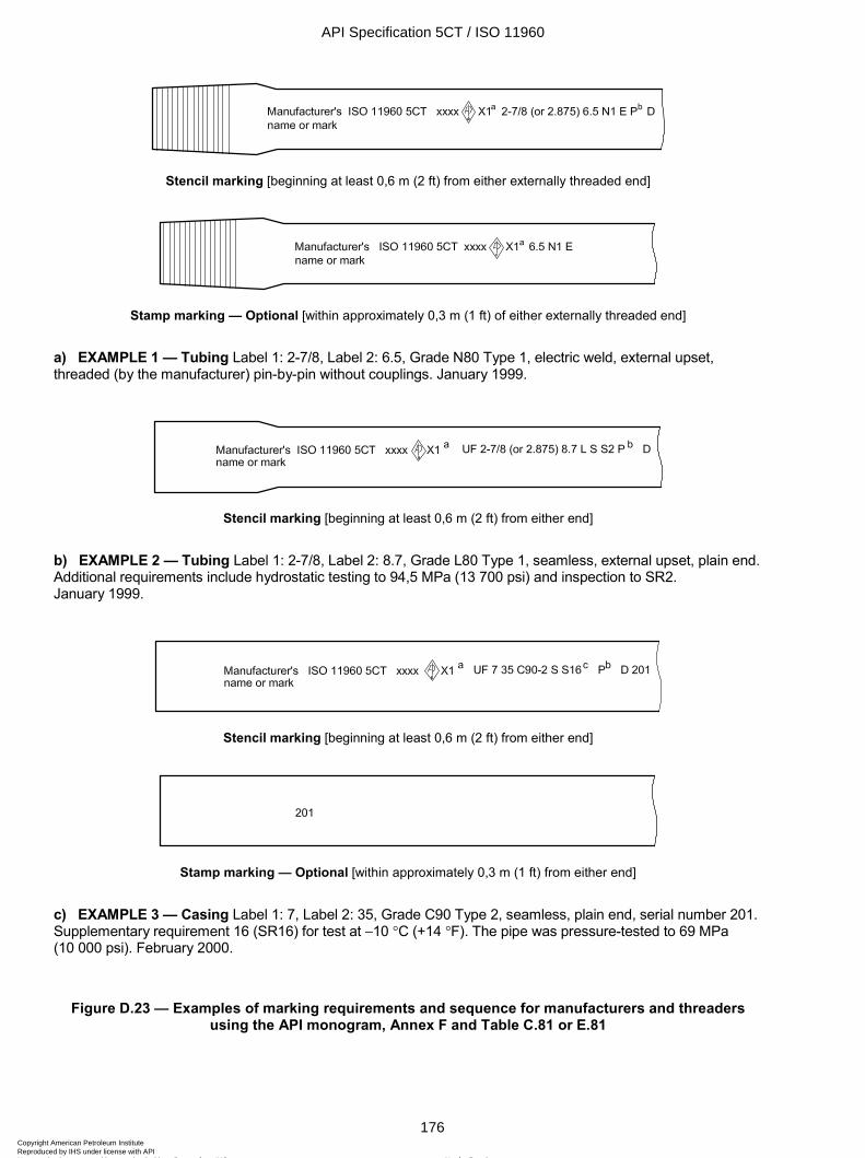
ISO 11960:2004(E)
176 © ISO 2004 – All rights reserved
Stencil marking [beginning at least 0,6 m (2 ft) from either externally threaded end]
Stamp marking — Optional [within approximately 0,3 m (1 ft) of either externally threaded end]
a) EXAMPLE 1 — Tubing Label 1: 2-7/8, Label 2: 6.5, Grade N80 Type 1, electric weld, external upset, threaded (by the manufacturer) pin-by-pin without couplings. January 1999.
Stencil marking [beginning at least 0,6 m (2 ft) from either end]
b) EXAMPLE 2 — Tubing Label 1: 2-7/8, Label 2: 8.7, Grade L80 Type 1, seamless, external upset, plain end. Additional requirements include hydrostatic testing to 94,5 MPa (13 700 psi) and inspection to SR2. January 1999.
Stencil marking [beginning at least 0,6 m (2 ft) from either end]
Stamp marking — Optional [within approximately 0,3 m (1 ft) from either end]
c) EXAMPLE 3 — Casing Label 1: 7, Label 2: 35, Grade C90 Type 2, seamless, plain end, serial number 201. Supplementary requirement 16 (SR16) for test at -10 ∞C (+14 ∞F). The pipe was pressure-tested to 69 MPa (10 000 psi). February 2000.
Figure D.23 — Examples of marking requirements and sequence for manufacturers and threaders using the API monogram, Annex F and Table C.81 or E.81
API Specification 5CT / ISO 11960
176Copyright American Petroleum Institute Reproduced by IHS under license with API
Not for ResaleNo reproduction or networking permitted without license from IHS
--`,,,```-`-`,,`,,`,`,,`---
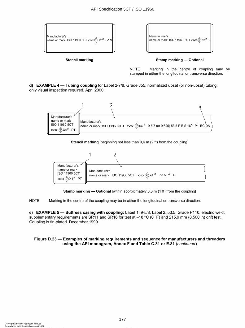
ISO 11960:2004(E)
© ISO 2004 – All rights reserved 177
Stencil marking Stamp marking — Optional
NOTE Marking in the centre of coupling may be stamped in either the longitudinal or transverse direction.
d) EXAMPLE 4 — Tubing coupling for Label 2-7/8, Grade J55, normalized upset (or non-upset) tubing, only visual inspection required. April 2000.
Stencil marking [beginning not less than 0,6 m (2 ft) from the coupling]
Stamp marking — Optional [within approximately 0,3 m (1 ft) from the coupling]
NOTE Marking in the centre of the coupling may be in either the longitudinal or transverse direction.
e) EXAMPLE 5 — Buttress casing with coupling: Label 1: 9-5/8, Label 2: 53.5, Grade P110, electric weld; supplementary requirements are SR11 and SR16 for test at -18 ∞C (0 ∞F) and 215,9 mm (8.500 in) drift test. Coupling is tin-plated. December 1999.
Figure D.23 — Examples of marking requirements and sequence for manufacturers and threaders using the API monogram, Annex F and Table C.81 or E.81 (continued)
API Specification 5CT / ISO 11960
177Copyright American Petroleum Institute Reproduced by IHS under license with API
Not for ResaleNo reproduction or networking permitted without license from IHS
--`,,,```-`-`,,`,,`,`,,`---
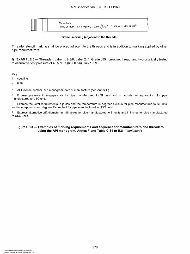
ISO 11960:2004(E)
178 © ISO 2004 – All rights reserved
Stencil marking (adjacent to the threads)
Threader stencil marking shall be placed adjacent to the threads and is in addition to marking applied by other pipe manufacturers.
f) EXAMPLE 6 — Threader: Label 1: 2-3/8, Label 2: 4, Grade J55 non-upset thread, and hydrostatically tested to alternative test pressure of 43,5 MPa (6 300 psi). July 1999.
Key 1 coupling 2 pipe
a API license number, API monogram, date of manufacture (see Annex F). b Express pressure in megapascals for pipe manufactured to SI units and in pounds per square inch for pipe manufactured to USC units. c Express the CVN requirements in joules and the temperature in degrees Celsius for pipe manufactured to SI units, and in foot-pounds and degrees Fahrenheit for pipe manufactured to USC units. d Express alternative drift diameter in millimetres for pipe manufactured to SI units and in inches for pipe manufactured to USC units.
Figure D.23 — Examples of marking requirements and sequence for manufacturers and threaders using the API monogram, Annex F and Table C.81 or E.81 (continued)
API Specification 5CT / ISO 11960
178Copyright American Petroleum Institute Reproduced by IHS under license with API
Not for ResaleNo reproduction or networking permitted without license from IHS
--`,,,```-`-`,,`,,`,`,,`---
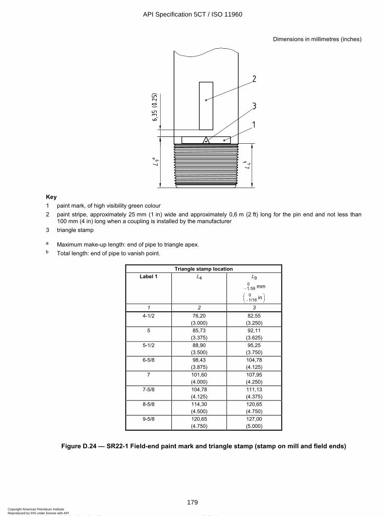
ISO 11960:2004(E)
© ISO 2004 – All rights reserved 179
Dimensions in millimetres (inches)
Key 1 paint mark, of high visibility green colour 2 paint stripe, approximately 25 mm (1 in) wide and approximately 0,6 m (2 ft) long for the pin end and not less than
100 mm (4 in) long when a coupling is installed by the manufacturer 3 triangle stamp
a Maximum make-up length: end of pipe to triangle apex. b Total length: end of pipe to vanish point.
Triangle stamp location Label 1 L4 L9
01, 59− mm 01/16 in−
1 2 3 4-1/2 76,20
(3.000) 82,55
(3.250) 5 85,73
(3.375) 92,11
(3.625) 5-1/2 88,90
(3.500) 95,25
(3.750) 6-5/8 98,43
(3.875) 104,78 (4.125)
7 101,60 (4.000)
107,95 (4.250)
7-5/8 104,78 (4.125)
111,13 (4.375)
8-5/8 114,30 (4.500)
120,65 (4.750)
9-5/8 120,65 (4.750)
127,00 (5.000)
Figure D.24 — SR22-1 Field-end paint mark and triangle stamp (stamp on mill and field ends)
API Specification 5CT / ISO 11960
179Copyright American Petroleum Institute Reproduced by IHS under license with API
Not for ResaleNo reproduction or networking permitted without license from IHS
--`,,,```-`-`,,`,,`,`,,`---
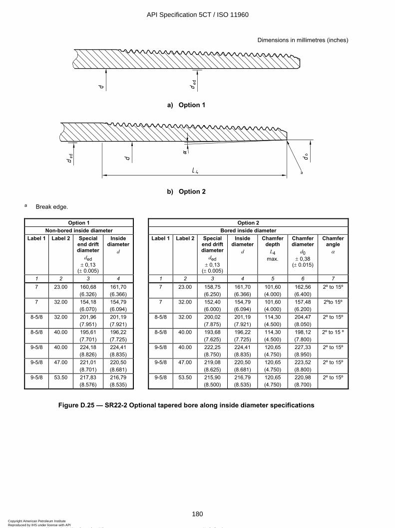
ISO 11960:2004(E)
180 © ISO 2004 – All rights reserved
Dimensions in millimetres (inches)
a) Option 1
b) Option 2
a Break edge.
Option 1 Option 2 Non-bored inside diameter Bored inside diameter
Label 1 Label 2 Special end drift diameter
ded ± 0,13
(± 0.005)
Inside diameter
d
Label 1 Label 2 Special end drift diameter
ded ± 0,13
(± 0.005)
Inside diameter
d
Chamfer depth
L4 max.
Chamfer diameter
d0 ± 0,38
(± 0.015)
Chamfer angle
α
1 2 3 4 1 2 3 4 5 6 7 7 23.00 160,68
(6.326) 161,70 (6.366)
7 23.00 158,75 (6.250)
161,70 (6.366)
101,60 (4.000)
162,56 (6.400)
2º to 15º
7 32.00 154,18 (6.070)
154,79 (6.094)
7 32.00 152,40 (6.000)
154,79 (6.094)
101,60 (4.000)
157,48 (6.200)
2ºto 15º
8-5/8 32.00 201,96 (7.951)
201,19 (7.921)
8-5/8 32.00 200,02 (7.875)
201,19 (7.921)
114,30 (4.500)
204,47 (8.050)
2º to 15º
8-5/8 40.00 195,61 (7.701)
196,22 (7.725)
8-5/8 40.00 193,68 (7.625)
196,22 (7.725)
114,30 (4.500)
198,12 (7.800)
2º to 15 º
9-5/8 40.00 224,18 (8.826)
224,41 (8.835)
9-5/8 40.00 222,25 (8.750)
224,41 (8.835)
120,65 (4.750)
227,33 (8.950)
2º to 15º
9-5/8 47.00 221,01 (8.701)
220,50 (8.681)
9-5/8 47.00 219,08 (8.625)
220,50 (8.681)
120,65 (4.750)
223,52 (8.800)
2º to 15º
9-5/8 53.50 217,83 (8.576)
216,79 (8.535)
9-5/8 53.50 215,90 (8.500)
216,79 (8.535)
120,65 (4.750)
220,98 (8.700)
2º to 15º
Figure D.25 — SR22-2 Optional tapered bore along inside diameter specifications
API Specification 5CT / ISO 11960
180Copyright American Petroleum Institute Reproduced by IHS under license with API
Not for ResaleNo reproduction or networking permitted without license from IHS
--`,,,```-`-`,,`,,`,`,,`---
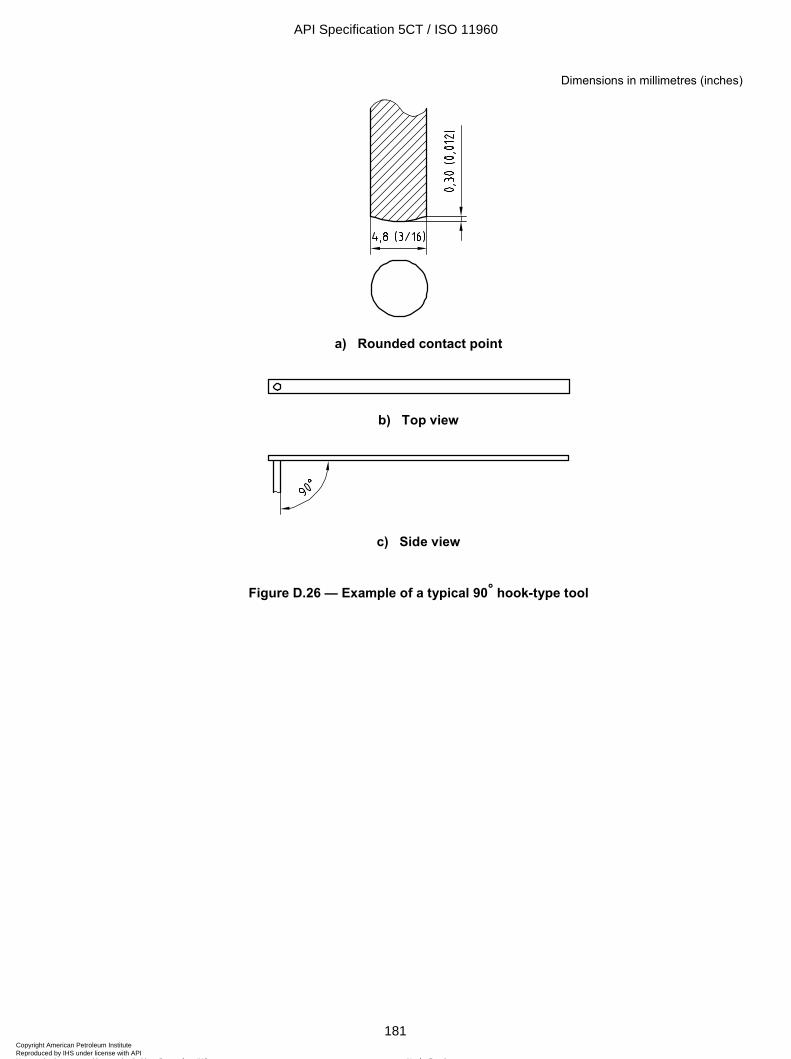
ISO 11960:2004(E)
© ISO 2004 – All rights reserved 181
Dimensions in millimetres (inches)
a) Rounded contact point
b) Top view
c) Side view
Figure D.26 — Example of a typical 90° hook-type tool
API Specification 5CT / ISO 11960
181Copyright American Petroleum Institute Reproduced by IHS under license with API
Not for ResaleNo reproduction or networking permitted without license from IHS
--`,,,```-`-`,,`,,`,`,,`---
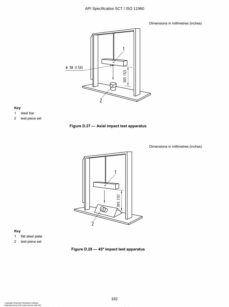
ISO 11960:2004(E)
182 © ISO 2004 – All rights reserved
Dimensions in millimetres (inches)
Key 1 steel bar 2 test-piece set
Figure D.27 — Axial impact test apparatus
Dimensions in millimetres (inches)
Key 1 flat steel plate 2 test-piece set
Figure D.28 — 45º impact test apparatus
API Specification 5CT / ISO 11960
182Copyright American Petroleum Institute Reproduced by IHS under license with API
Not for ResaleNo reproduction or networking permitted without license from IHS
--`,,,```-`-`,,`,,`,`,,`---
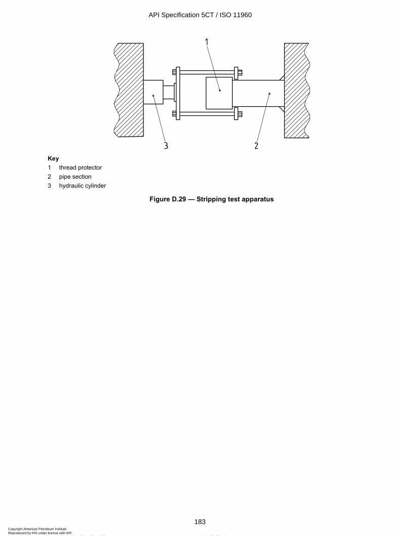
ISO 11960:2004(E)
© ISO 2004 – All rights reserved 183
Key 1 thread protector 2 pipe section 3 hydraulic cylinder
Figure D.29 — Stripping test apparatus
API Specification 5CT / ISO 11960
183Copyright American Petroleum Institute Reproduced by IHS under license with API
Not for ResaleNo reproduction or networking permitted without license from IHS
--`,,,```-`-`,,`,,`,`,,`---
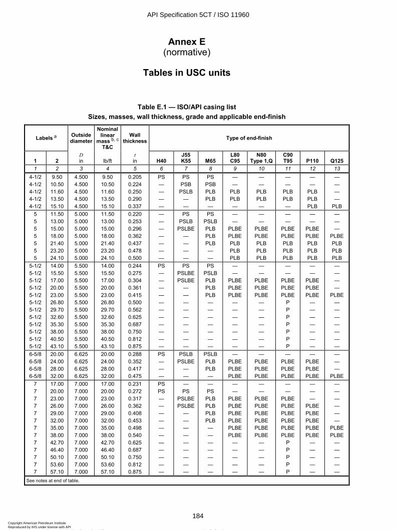
ISO 11960:2004(E)
184 © ISO 2004 – All rights reserved
Annex E (normative)
Tables in USC units
Table E.1 — ISO/API casing list Sizes, masses, wall thickness, grade and applicable end-finish
Labels a Outside diameter
Nominal linear
mass b, c
T&C
Wall thickness Type of end-finish
1
2
D in
lb/ft
t in
H40
J55 K55
M65
L80 C95
N80 Type 1,Q
C90 T95
P110
Q125
1 2 3 4 5 6 7 8 9 10 11 12 13 4-1/2 4-1/2 4-1/2 4-1/2 4-1/2
9.50 10.50 11.60 13.50 15.10
4.500 4.500 4.500 4.500 4.500
9.50 10.50 11.60 13.50 15.10
0.205 0.224 0.250 0.290 0.337
PS — — — —
PS PSB
PSLB — —
PS PSB PLB PLB —
— —
PLB PLB —
— —
PLB PLB —
— —
PLB PLB —
— —
PLB PLB PLB
— — — —
PLB 5 5 5 5 5 5 5
11.50 13.00 15.00 18.00 21.40 23.20 24.10
5.000 5.000 5.000 5.000 5.000 5.000 5.000
11.50 13.00 15.00 18.00 21.40 23.20 24.10
0.220 0.253 0.296 0.362 0.437 0.478 0.500
— — — — — — —
PS PSLB
PSLBE — — — —
PS PSLB PLB PLB PLB — —
— —
PLBE PLBE PLB PLB PLB
— —
PLBE PLBE PLB PLB PLB
— —
PLBE PLBE PLB PLB PLB
— —
PLBE PLBE PLB PLB PLB
— — —
PLBE PLB PLB PLB
5-1/2 5-1/2 5-1/2 5-1/2 5-1/2 5-1/2 5-1/2 5-1/2 5-1/2 5-1/2 5-1/2 5-1/2
14.00 15.50 17.00 20.00 23.00 26.80 29.70 32.60 35.30 38.00 40.50 43.10
5.500 5.500 5.500 5.500 5.500 5.500 5.500 5.500 5.500 5.500 5.500 5.500
14.00 15.50 17.00 20.00 23.00 26.80 29.70 32.60 35.30 38.00 40.50 43.10
0.244 0.275 0.304 0.361 0.415 0.500 0.562 0.625 0.687 0.750 0.812 0.875
PS — — — — — — — — — — —
PS PSLBE PSLBE
— — — — — — — — —
PS PSLB PLB PLB PLB — — — — — — —
— —
PLBE PLBE PLBE
— — — — — — —
— —
PLBE PLBE PLBE
— — — — — — —
— —
PLBE PLBE PLBE
P P P P P P P
— —
PLBE PLBE PLBE
— — — — — — —
— — — —
PLBE — — — — — — —
6-5/8 6-5/8 6-5/8 6-5/8
20.00 24.00 28.00 32.00
6.625 6.625 6.625 6.625
20.00 24.00 28.00 32.00
0.288 0.352 0.417 0.475
PS — — —
PSLB PSLBE
— —
PSLB PLB PLB —
— PLBE PLBE PLBE
— PLBE PLBE PLBE
— PLBE PLBE PLBE
— PLBE PLBE PLBE
— — —
PLBE 7 7 7 7 7 7 7 7 7 7 7 7 7
17.00 20.00 23.00 26.00 29.00 32.00 35.00 38.00 42.70 46.40 50.10 53.60 57.10
7.000 7.000 7.000 7.000 7.000 7.000 7.000 7.000 7.000 7.000 7.000 7.000 7.000
17.00 20.00 23.00 26.00 29.00 32.00 35.00 38.00 42.70 46.40 50.10 53.60 57.10
0.231 0.272 0.317 0.362 0.408 0.453 0.498 0.540 0.625 0.687 0.750 0.812 0.875
PS PS — — — — — — — — — — —
— PS
PSLBE PSLBE
— — — — — — — — —
— PS
PLB PLB PLB PLB — — — — — — —
— —
PLBE PLBE PLBE PLBE PLBE PLBE
— — — — —
— —
PLBE PLBE PLBE PLBE PLBE PLBE
— — — — —
— —
PLBE PLBE PLBE PLBE PLBE PLBE
P P P P P
— — —
PLBE PLBE PLBE PLBE PLBE
— — — — —
— — — — — —
PLBE PLBE
— — — — —
See notes at end of table.
API Specification 5CT / ISO 11960
184Copyright American Petroleum Institute Reproduced by IHS under license with API
Not for ResaleNo reproduction or networking permitted without license from IHS
--`,,,```-`-`,,`,,`,`,,`---
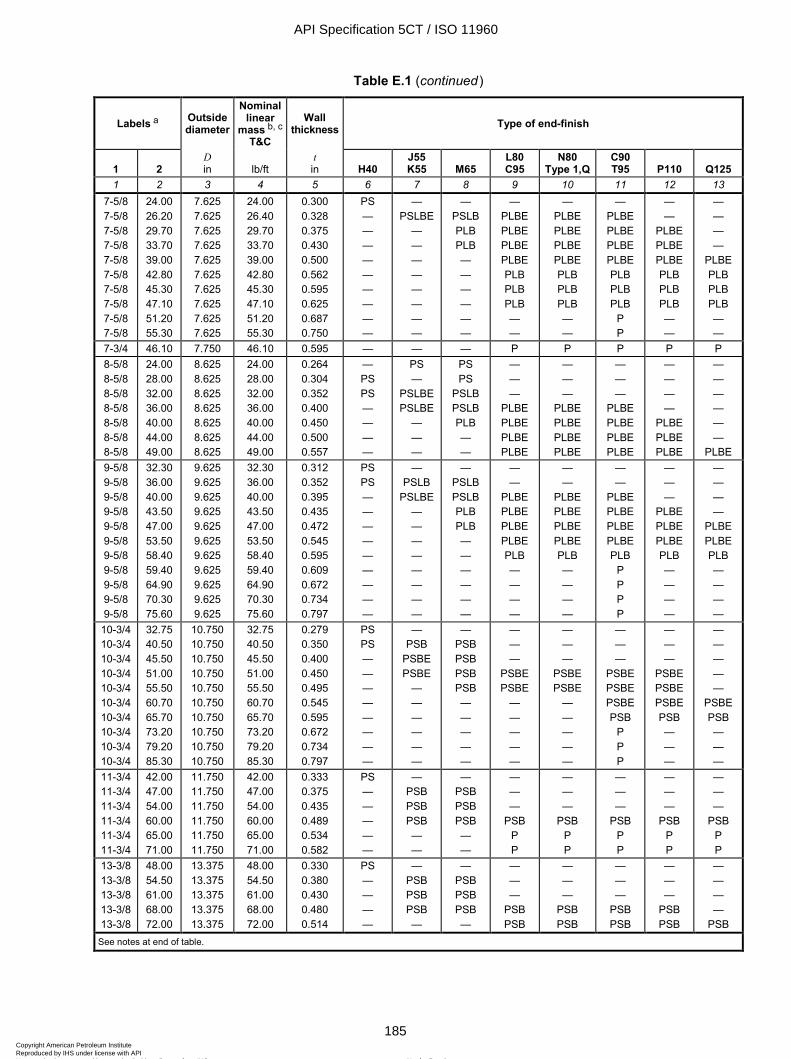
ISO 11960:2004(E)
© ISO 2004 – All rights reserved 185
Table E.1 (continued)
Labels a Outside diameter
Nominal linear
mass b, c T&C
Wall thickness Type of end-finish
1
2
D in
lb/ft
t in
H40
J55 K55
M65
L80 C95
N80 Type 1,Q
C90 T95
P110
Q125
1 2 3 4 5 6 7 8 9 10 11 12 13 7-5/8 7-5/8 7-5/8 7-5/8 7-5/8 7-5/8 7-5/8 7-5/8 7-5/8 7-5/8
24.00 26.20 29.70 33.70 39.00 42.80 45.30 47.10 51.20 55.30
7.625 7.625 7.625 7.625 7.625 7.625 7.625 7.625 7.625 7.625
24.00 26.40 29.70 33.70 39.00 42.80 45.30 47.10 51.20 55.30
0.300 0.328 0.375 0.430 0.500 0.562 0.595 0.625 0.687 0.750
PS — — — — — — — — —
— PSLBE
— — — — — — — —
— PSLB PLB PLB — — — — — —
— PLBE PLBE PLBE PLBE PLB PLB PLB — —
— PLBE PLBE PLBE PLBE PLB PLB PLB — —
— PLBE PLBE PLBE PLBE PLB PLB PLB
P P
— —
PLBE PLBE PLBE PLB PLB PLB — —
— — — —
PLBE PLB PLB PLB — —
7-3/4 46.10 7.750 46.10 0.595 — — — P P P P P 8-5/8 8-5/8 8-5/8 8-5/8 8-5/8 8-5/8 8-5/8
24.00 28.00 32.00 36.00 40.00 44.00 49.00
8.625 8.625 8.625 8.625 8.625 8.625 8.625
24.00 28.00 32.00 36.00 40.00 44.00 49.00
0.264 0.304 0.352 0.400 0.450 0.500 0.557
— PS PS — — — —
PS —
PSLBE PSLBE
— — —
PS PS
PSLB PSLB PLB — —
— — —
PLBE PLBE PLBE PLBE
— — —
PLBE PLBE PLBE PLBE
— — —
PLBE PLBE PLBE PLBE
— — — —
PLBE PLBE PLBE
— — — — — —
PLBE 9-5/8 9-5/8 9-5/8 9-5/8 9-5/8 9-5/8 9-5/8 9-5/8 9-5/8 9-5/8 9-5/8
32.30 36.00 40.00 43.50 47.00 53.50 58.40 59.40 64.90 70.30 75.60
9.625 9.625 9.625 9.625 9.625 9.625 9.625 9.625 9.625 9.625 9.625
32.30 36.00 40.00 43.50 47.00 53.50 58.40 59.40 64.90 70.30 75.60
0.312 0.352 0.395 0.435 0.472 0.545 0.595 0.609 0.672 0.734 0.797
PS PS — — — — — — — — —
— PSLB
PSLBE — — — — — — — —
— PSLB PSLB PLB PLB — — — — — —
— —
PLBE PLBE PLBE PLBE PLB — — — —
— —
PLBE PLBE PLBE PLBE PLB — — — —
— —
PLBE PLBE PLBE PLBE PLB
P P P P
— — —
PLBE PLBE PLBE PLB — — — —
— — — —
PLBE PLBE PLB — — — —
10-3/4 10-3/4 10-3/4 10-3/4 10-3/4 10-3/4 10-3/4 10-3/4 10-3/4 10-3/4
32.75 40.50 45.50 51.00 55.50 60.70 65.70 73.20 79.20 85.30
10.750 10.750 10.750 10.750 10.750 10.750 10.750 10.750 10.750 10.750
32.75 40.50 45.50 51.00 55.50 60.70 65.70 73.20 79.20 85.30
0.279 0.350 0.400 0.450 0.495 0.545 0.595 0.672 0.734 0.797
PS PS — — — — — — — —
— PSB
PSBE PSBE
— — — — — —
— PSB PSB PSB PSB — — — — —
— — —
PSBE PSBE
— — — — —
— — —
PSBE PSBE
— — — — —
— — —
PSBE PSBE PSBE PSB
P P P
— — —
PSBE PSBE PSBE PSB — — —
— — — — —
PSBE PSB — — —
11-3/4 11-3/4 11-3/4 11-3/4 11-3/4 11-3/4
42.00 47.00 54.00 60.00 65.00 71.00
11.750 11.750 11.750 11.750 11.750 11.750
42.00 47.00 54.00 60.00 65.00 71.00
0.333 0.375 0.435 0.489 0.534 0.582
PS — — — — —
— PSB PSB PSB — —
— PSB PSB PSB — —
— — —
PSB P P
— — —
PSB P P
— — —
PSB P P
— — —
PSB P P
— — —
PSB P P
13-3/8 13-3/8 13-3/8 13-3/8 13-3/8
48.00 54.50 61.00 68.00 72.00
13.375 13.375 13.375 13.375 13.375
48.00 54.50 61.00 68.00 72.00
0.330 0.380 0.430 0.480 0.514
PS — — — —
— PSB PSB PSB —
— PSB PSB PSB —
— — —
PSB PSB
— — —
PSB PSB
— — —
PSB PSB
— — —
PSB PSB
— — — —
PSB See notes at end of table.
API Specification 5CT / ISO 11960
185Copyright American Petroleum Institute Reproduced by IHS under license with API
Not for ResaleNo reproduction or networking permitted without license from IHS
--`,,,```-`-`,,`,,`,`,,`---
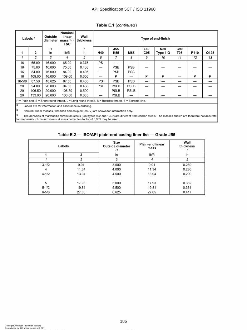
ISO 11960:2004(E)
186 © ISO 2004 – All rights reserved
Table E.1 (continued)
Labels a Outside diameter
Nominal linear
mass b, c
T&C
Wall thickness Type of end-finish
1
2
D in
lb/ft
t in
H40
J55 K55
M65
L80 C95
N80 Type 1,Q
C90 T95
P110
Q125
1 2 3 4 5 6 7 8 9 10 11 12 13 16 16 16 16
65.00 75.00 84.00 109.00
16.000 16.000 16.000 16.000
65.00 75.00 84.00
109.00
0.375 0.438 0.495 0.656
PS — — —
— PSB PSB
P
— PSB PSB —
— — — P
— — — P
— — — —
— — — P
— — — P
18-5/8 87.50 18.625 87.50 0.435 PS PSB PSB — — — — — 20 20 20
94.00 106.50 133.00
20.000 20.000 20.000
94.00 106.50 133.00
0.438 0.500 0.635
PSL — —
PSLB PSLB PSLB
PSLB PSLB
—
— — —
— — —
— — —
— — —
— — —
P = Plain end, S = Short round thread, L = Long round thread, B = Buttress thread, E = Extreme-line. a Labels are for information and assistance in ordering. b Nominal linear masses, threaded and coupled (col. 2) are shown for information only. c The densities of martensitic chromium steels (L80 types 9Cr and 13Cr) are different from carbon steels. The masses shown are therefore not accurate for martensitic chromium steels. A mass correction factor of 0,989 may be used.
Table E.2 — ISO/API plain-end casing liner list — Grade J55
Labels Size
Outside diameter D
Plain-end linear mass
Wall thickness
t 1 2 in lb/ft in 1 2 3 4 5
3-1/2 9.91 3.500 9.91 0.289 4 11.34 4.000 11.34 0.286
4-1/2 13.04 4.500 13.04 0.290 5 17.93 5.000 17.93 0.362
5-1/2 19.81 5.500 19.81 0.361 6-5/8 27.65 6.625 27.65 0.417
API Specification 5CT / ISO 11960
186Copyright American Petroleum Institute Reproduced by IHS under license with API
Not for ResaleNo reproduction or networking permitted without license from IHS
--`,,,```-`-`,,`,,`,`,,`---
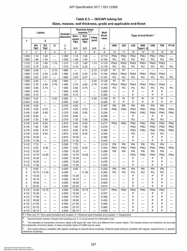
ISO 11960:2004(E)
© ISO 2004 – All rights reserved 187
Table E.3 — ISO/API tubing list Sizes, masses, wall thickness, grade and applicable end-finish
Nominal linear masses a, b Labels
1 2
Outside diameter Non-
upset T&C
Ext. upset T&C
Integ. joint
Wall thick-ness
Type of end-finish c
NU T&C
EU T&C
IJ D in
lb/ft
lb/ft
lb/ft
t in
H40 J55 L80 N80 Type1, Q
C90 T95 P110
1 2 3 4 5 6 7 8 9 10 11 12 13 14 15 16 1.050 1.050
1.14 1.48
1.20 1.54
— —
1.050 1.050
1.14 1.48
1.20 1.54
— —
0.113 0.154
PNU PU
PNU PU
PNU PU
PNU PU
PNU PU
PNU PU
— PU
1.315 1.315
1.70 2.19
1.80 2.24
1.72 —
1.315 1.315
1.70 2.19
1.80 2.24
1.72 —
0.133 0.179
PNUI PU
PNUI PU
PNUI PU
PNUI PU
PNUI PU
PNUI PU
— PU
1.660 1.660 1.660
2.09 2.30 3.03
— 2.40 3.07
2.10 2.33 —
1.660 1.660 1.660
— 2.30 3.03
— 2.40 3.07
2.10 2.33 —
0.125 0.140 0.191
PI PNUI PU
PI PNUI PU
— PNUI PU
— PNUI PU
— PNUI PU
— PNUI PU
— — PU
1.900 1.900 1.900 1.900 1.900
2.40 2.75 3.65 4.42 5.15
— 2.90 3.73 — —
2.40 2.76 — —
1.900 1.900 1.900 1.900 1.900
— 2.75 3.65 4.42 5.15
— 2.90 3.73 — —
2.40 2.76 — — —
0.125 0.145 0.200 0.250 0.300
PI PNUI PU — —
PI PNUI PU — —
— PNUI PU P P
— PNUI PU — —
— PNU I
PU P P
— PNUI PU P P
— — PU — —
2.063 2.063
3.24 4.50
— —
3.25 —
2.063 2.063
— 4.50
— —
3.25 —
0.156 0.225
PI P
PI P
PI P
PI P
PI P
PI P
— P
2-3/8 2-3/8 2-3/8 2-3/8 2-3/8
4.00 4.60 5.80 6.60 7.35
— 4.70 5.95 —
7.45
— — — — —
2.375 2.375 2.375 2.375 2.375
4.00 4.60 5.80 6.60 7.35
— 4.70 5.95 —
7.45
— — — — —
0.167 0.190 0.254 0.295 0.336
PN PNU — — —
PN PNU — — —
PN PNU PNU
P PU
PN PNU PNU — —
PN PNU PNU
P PU
PN PNU PNU
P PU
— PNU PNU — —
2-7/8 2-7/8 2-7/8 2-7/8 2-7/8 2-7/8
6.40 7.80 8.60 9.35 10.50 11.50
6.50 7.90 8.70 9.45 — —
— — — — — —
2.875 2.875 2.875 2.875 2.875 2.875
6.40 7.80 8.60 9.35 10.50 11.50
6.50 7.90 8.70 9.45 — —
— — —- — — —
0.217 0.276 0.308 0.340 0.392 0.440
PNU — — — — —
PNU — — — — —
PNU PNU PNU PU P P
PNU PNU PNU — — —
PNU PNU PNU PU P P
PNU PNU PNU PU P P
PNU PNU PNU — — —
3-1/2 3-1/2 3-1/2 3-1/2 3-1/2 3-1/2 3-1/2
7.70 9.20 10.20 12.70 14.30 15.50 17.00
— 9.30
— 12.95
— — —
— — — — — — —
3.500 3.500 3.500 3.500 3.500 3.500 3.500
7.70 9.20 10.20 12.70 14.30 15.50 17.00
— 9.30 —
12.95 — — —
— — — — — — —
0.216 0.254 0.289 0.375 0.430 0.476 0.530
PN PNU PN — — — —
PN PNU PN — — — —
PN PNU PN
PNU P P P
PN PNU PN
PNU — — —
PN PNU PN
PNU P P P
PN PNU PN
PNU P P P
— PNU —
PNU — — —
4 4 4 4 4 4
9.50 10.70 13.20 16.10 18.90 22.20
— 11.00
— — — —
— — — — — —
4.000 4.000 4.000 4.000 4.000 4.000
9.50 —
13.20 16.10 18.90 22.20
— 11.00
— — — —
— — — — — —
0.226 0.262 0.330 0.415 0.500 0.610
PN PU — — — —
PN PU — — — —
PN PU P P P P
PN PU — — — —
PN PU P P P P
PN PU P P P P
— — — — — —
4-1/2 4-1/2 4-1/2 4-1/2 4-1/2 4-1/2 4-1/2
12.60 15.20 17.00 18.90 21.50 23.70 26.10
12.75 — — — — — —
— — — — — — —
4.500 4.500 4.500 4.500 4.500 4.500 4.500
12.60 15.20 17.00 18.90 21.50 23.70 26.10
12.75 — — — — — —
— — — — — — —
0.271 0.337 0.380 0.430 0.500 0.560 0.630
PNU — — — — — —
PNU — — — — — —
PNU P P P P P P
PNU — — — — — —
PNU P P P P P P
PNU P P P P P P
— — — — — — —
P = Plain end, N = Non-upset threaded and coupled, U = External upset threaded and coupled, I = Integral joint.
a Nominal linear masses, threads and coupling (col. 2, 3, 4) are shown for information only. b The densities of martensitic chromium steels (L80 types 9Cr and 13Cr) are different from carbon steels. The masses shown are therefore not accurate for martensitic chromium steels. A mass correction factor of 0.989 may be used. c Non-upset tubing is available with regular couplings or special bevel couplings. External-upset tubing is available with regular, special-bevel, or special-clearance couplings.
API Specification 5CT / ISO 11960
187Copyright American Petroleum Institute Reproduced by IHS under license with API
Not for ResaleNo reproduction or networking permitted without license from IHS
--`,,,```-`-`,,`,,`,`,,`---
ISO 11960:2004(E)
188 © ISO 2004 – All rights reserved
Table E.4 — Process of manufacture and heat treatment
Group Grade Type Manufacturing process a Heat treatment Tempering temperature
°F min.
1 2 3 4 5 6 1 H40
J55 K55 N80 N80
— — — 1 Q
S or EW S or EW S or EW S or EW S or EW
None None b None b
c
Q&T
— — — — —
2 M65 L80 L80 L80 C90 C90 C95 T95 T95
— 1
9Cr 13Cr
1 2 — 1 2
S or EW S or EW
S S S S
S or EW S S
d
Q&T Q&T e Q&T e Q&T Q&T Q&T Q&T Q&T
— 1 050 1 100 1 100 1 150 1 150 1 000 1 200 1 200
3 P110 — S or EW f, g Q&T — 4 Q125
Q125 Q125 Q125
1 2 3 4
S or EW g S or EW g S or EW g S or EW g
Q&T Q&T Q&T Q&T
— — — —
a S = seamless process; EW = electric-welded process. b Full length normalized (N), normalized and tempered (N&T), or quenched and tempered (Q&T), at the manufacturer's option or as specified on the purchase agreement. c Full length normalized or normalized and tempered at the manufacturer's option. d All pipe shall be full body heat-treated. Full length normalized (N), normalized and tempered (N&T), or quenched and tempered (Q&T), at the manufacturer's option or as specified on the purchase agreement. e Types 9Cr and 13Cr may be air-quenched. f Special chemical requirements for electric-welded P110 casing are specified in Table C.5. g Special requirements unique to electric-welded P110 and Q125 are specified in A.6 (SR11).
API Specification 5CT / ISO 11960
188Copyright American Petroleum Institute Reproduced by IHS under license with API
Not for ResaleNo reproduction or networking permitted without license from IHS
--`,,,```-`-`,,`,,`,`,,`---
ISO 11960:2004(E)
© ISO 2004 – All rights reserved 189
Table E.5 — Chemical composition, mass fraction (%)
C Mn Mo Cr Ni Cu P S Si Group Grade Type min. max. min. max. min. max. min. max. max. max. max. max. max.
1 2 3 4 5 6 7 8 9 10 11 12 13 14 15 16 H40 — — — — — — — — — — — 0.030 0.030 — J55 — — — — — — — — — — — 0.030 0.030 — K55 — — — — — — — — — — — 0.030 0.030 — N80 1 — — — — — — — — — — 0.030 0.030 —
1
N80 Q — — — — — — — — — — 0.030 0.030 — M65 — — — — — — — — — — — 0.030 0.030 — L80 1 — 0.43 a — 1.90 — — — — 0.25 0.35 0.030 0.030 0.45 L80 9Cr — 0.15 0.30 0.60 0.90 1.10 8.00 10.0 0.50 0.25 0.020 0.010 1.00 L80 13Cr 0.15 0.22 0.25 1.00 — — 12.0 14.0 0.50 0.25 0.020 0.010 1.00 C90 1 — 0.35 — 1.20 0.25 b 0.85 — 1.50 0.99 — 0.020 0.010 — C90 2 — 0.50 — 1.90 — NL — NL 0.99 — 0.030 0.010 — C95 — — 0.45 c — 1.90 — — — — — — 0.030 0.030 0.45 T95 1 — 0.35 — 1.20 0.25 d 0.85 0.40 1.50 0.99 — 0.020 0.010 —
2
T95 2 — 0.50 — 1.90 — — — — 0.99 — 0.030 0.010 — 3 P110 e — — — — — — — — — — 0.030 e 0.030 e —
Q125 1 — 0.35 1.35 — 0.85 — 1.50 0.99 — 0.020 0.010 — Q125 2 — 0.35 — 1.00 — NL — NL 0.99 — 0.020 0.020 — Q125 3 — 0.50 — 1.90 — NL — NL 0.99 — 0.030 0.010 —
4
Q125 4 — 0.50 — 1.90 — NL — NL 0.99 — 0.030 0.020 — a The carbon content for L80 may be increased up to 0.50 % max. if the product is oil-quenched. b The molybdenum content for Grade C90 Type 1 has no minimum tolerance if the wall thickness is less than 0.700 in. c The carbon content for C95 may be increased up to 0.55 % max. if the product is oil-quenched. d The molybdenum content for T95 Type 1 may be decreased to 0.15 % min. if the wall thickness is less than 0.700 in. e For EW Grade P110, the phosphorus content shall be 0.020 % max. and the sulfur content 0.010 % max.
NL = no limit. Elements shown shall be reported in product analysis.
API Specification 5CT / ISO 11960
189Copyright American Petroleum Institute Reproduced by IHS under license with API
Not for ResaleNo reproduction or networking permitted without license from IHS
--`,,,```-`-`,,`,,`,`,,`---
ISO 11960:2004(E)
190 © ISO 2004 – All rights reserved
Table E.6 — Tensile and hardness requirements
Total elongation under load
Yield strength
ksi
Tensile strength
min.
Hardness a
max. Specified wall
thickness Allowable hardness variation bGroup Grade Type
% min. max. ksi HRC HBW in HRC 1 2 3 4 5 6 7 8 9 10 11 1 H40
J55
K55
N80 N80
—
—
— 1 Q
0.5
0.5
0.5
0.5 0.5
40
55
55
80 80
80
80
80
110 110
60
75
95
100 100
—
—
—
— —
—
—
—
— —
—
—
—
— —
—
—
—
— —
2 M65
L80 L80 L80
C90 C90 C90 C90
C95
T95 T95 T95 T95
— 1
9Cr 13Cr
1, 2 1, 2 1, 2 1, 2
—
1, 2 1, 2 1, 2 1, 2
0.5
0.5 0.5 0.5
0.5 0.5 0.5 0.5
0.5
0.5 0.5 0.5 0.5
65
80 80 80
90 90 90 90
95
95 95 95 95
85
95 95 95
105 105 105 105
110
110 110 110 110
85
95 95 95
100 100 100 100
105
105 105 105 105
22
23 23 23
25.4 25.4 25.4 25.4
—
25.4 25.4 25.4 25.4
235
241 241 241
255 255 255 255
—
255 255 255 255
—
— — —
u 0.500 0.501 to 0.749 0.750 to 0.999
W 1.000
—
u 0.500 0.501 to 0.749 0.750 to 0.999
W 1.000
—
— — —
3.0 4.0 5.0 6.0
—
3.0 4.0 5.0 6.0
3 P110 — 0.6 110 140 125 — — — — 4 Q125
Q125 Q125
— — —
0.65 0.65 0.65
125 125 125
150 150 150
135 135 135
b b b
— — —
u 0.500 0.501 to 0.749
W 0.750
3.0 4.0 5.0
a In case of dispute, laboratory Rockwell C hardness testing shall be used as the referee method. b No hardness limits are specified, but the maximum variation is restricted as a manufacturing control in accordance with 7.8 and 7.9.
API Specification 5CT / ISO 11960
190Copyright American Petroleum Institute Reproduced by IHS under license with API
Not for ResaleNo reproduction or networking permitted without license from IHS
--`,,,```-`-`,,`,,`,`,,`---
ISO 11960:2004(E)
© ISO 2004 – All rights reserved 191
Table E.7 — Elongation table
Minimum elongation in 2.0 in %
Grade Tensile test specimen H40 J55 M65 K55
L80 N80-1 N80Q C90
C95 T95
P110 Q125
Specified wall thickness in
Specified minimum tensile strength ksi Specimen
area in2
Specimen width ¾ in
Specimen width 1 in
Specimen width 1½ in
60 75 85 95 100 105 125 135
1 2 3 4 5 6 7 8 9 10 11 12 0.750 W 0.994 W 0.746 W 0.497 30 24 22 20 19 18 15 14 0.740 0.980-0.993 0.735-0.745 0.490-0.496 29 24 22 19 19 18 15 14 0.730 0.967-0.979 0.726-0.734 0.484-0.489 29 24 21 19 19 18 15 14 0.720 0.954-0.966 0.715-0.725 0.477-0.483 29 24 21 19 19 18 15 14 0.710 0.941-0.953 0.706-0.714 0.471-0.476 29 24 21 19 18 18 15 14 0.700 0.927-0.940 0.695-0.705 0.464-0.470 29 24 21 19 18 18 15 14 0.690 0.914-0.926 0.686-0.694 0.457-0.463 29 24 21 19 18 18 15 14 0.680 0.900-0.913 0.675-0.685 0.450-0.456 29 24 21 19 18 18 15 14 0.670 0.887-0.899 0.666-0.674 0.444-0.449 29 24 21 19 18 17 15 14 0.660 0.874-0.886 0.655-0.665 0.437-0.443 29 24 21 19 18 17 15 14 0.650 0.861-0.873 0.646-0.654 0.431-0.436 29 23 21 19 18 17 15 14 0.640 0.847-0.860 0.635-0.645 0.424-0.430 29 23 21 19 18 17 15 14 0.630 0.834-0.846 0.626-0.634 0.417-0.423 29 23 21 19 18 17 15 14 0.620 0.820-0.833 0.615-0.625 0.410-0.416 28 23 21 19 18 17 15 14 0.610 0.807-0.819 0.606-0.614 0.404-0.409 28 23 21 19 18 17 15 14 0.600 0.794-0.806 0.595-0.605 0.397-0.403 28 23 21 19 18 17 15 14 0.590 0.781-0.793 0.586-0.594 0.391-0.396 28 23 21 19 18 17 15 14 0.580 0.767-0.780 0.575-0.585 0.384-0.390 28 23 21 19 18 17 14 14 0.570 0.754-0.766 0.566-0.574 0.377-0.383 28 23 20 18 18 17 14 13 0.560 0.740-0.753 0.555-0.565 0.370-0.376 28 23 20 18 18 17 14 13 0.550 0.727-0.739 0.546-0.554 0.364-0.369 28 23 20 18 18 17 14 13 0.540 0.714-0.726 0.535-0.545 0.357-0.363 28 23 20 18 17 17 14 13 0.530 0.701-0.713 0.526-0.534 0.351-0.356 28 23 20 18 17 17 14 13 0.520 0.687-0.700 0.515-0.525 0.344-0.350 27 22 20 18 17 17 14 13 0.510 0.674-0.686 0.506-0.514 0.337-0.343 27 22 20 18 17 17 14 13 0.500 0.660-0.673 0.495-0.505 0.330-0.336 27 22 20 18 17 16 14 13 0.490 0.647-0.659 0.486-0.494 0.324-0.329 27 22 20 18 17 16 14 13 0.480 0.634-0.646 0.475-0.485 0.317-0.323 27 22 20 18 17 16 14 13 0.470 0.621-0.633 0.466-0.474 0.311-0.316 27 22 20 18 17 16 14 13 0.460 0.607-0.620 0.455-0.465 0.304-0.310 27 22 20 18 17 16 14 13 0.450 0.594-0.606 0.446-0.454 0.297-0.303 27 22 20 18 17 16 14 13 0.440 0.580-0.593 0.435-0.445 0.290-0.296 27 22 19 18 17 16 14 13 0.430 0.567-0.579 0.426-0.434 0.284-0.289 26 22 19 17 17 16 14 13 0.420 0.554-0.566 0.415-0.425 0.277-0.283 26 22 19 17 17 16 14 13 0.410 0.541-0.553 0.406-0.414 0.271-0.276 26 21 19 17 17 16 14 13 0.400 0.527-0.540 0.395-0.405 0.264-0.270 26 21 19 17 16 16 13 13 0.390 0.514-0.526 0.386-0.394 0.257-0.263 26 21 19 17 16 16 13 12 0.380 0.500-0.513 0.375-0.385 0.250-0.256 26 21 19 17 16 16 13 12 0.370 0.487-0.499 0.366-0.374 0.244-0.249 26 21 19 17 16 16 13 12 0.360 0.474-0.486 0.355-0.365 0.237-0.243 26 21 19 17 16 15 13 12 0.350 0.461-0.473 0.346-0.354 0.231-0.236 25 21 19 17 16 15 13 12 0.340 0.447-0.460 0.335-0.345 0.224-0.230 25 21 18 17 16 15 13 12 0.330 0.434-0.446 0.326-0.334 0.217-0.223 25 21 18 17 16 15 13 12 0.320 0.420-0.433 0.315-0.325 0.210-0.216 25 20 18 16 16 15 13 12 0.310 0.407-0.419 0.306-0.314 0.204-0.209 25 20 18 16 16 15 13 12 0.300 0.394-0.406 0.295-0.305 0.197-0.203 25 20 18 16 16 15 13 12
API Specification 5CT / ISO 11960
191Copyright American Petroleum Institute Reproduced by IHS under license with API
Not for ResaleNo reproduction or networking permitted without license from IHS
--`,,,```-`-`,,`,,`,`,,`---
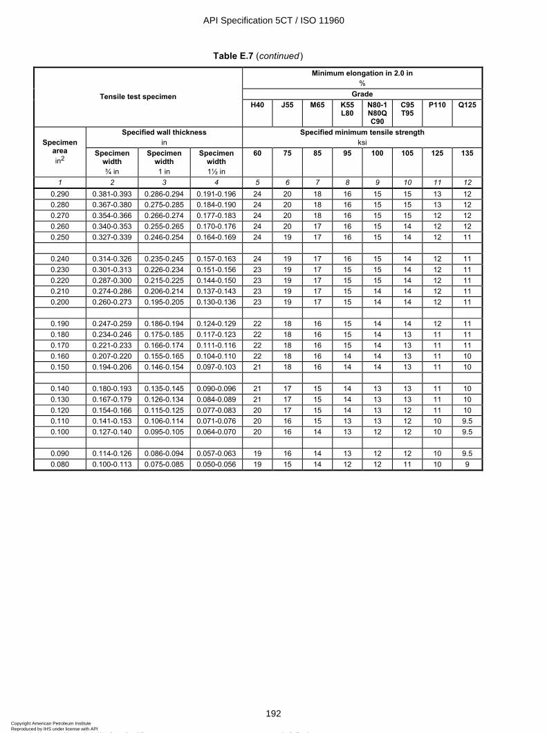
ISO 11960:2004(E)
192 © ISO 2004 – All rights reserved
Table E.7 (continued)
Minimum elongation in 2.0 in %
Grade Tensile test specimen H40 J55 M65 K55
L80 N80-1 N80Q C90
C95 T95
P110 Q125
Specified wall thickness in
Specified minimum tensile strength ksi Specimen
area in2
Specimen width ¾ in
Specimen width 1 in
Specimen width 1½ in
60 75 85 95 100 105 125 135
1 2 3 4 5 6 7 8 9 10 11 12 0.290 0.381-0.393 0.286-0.294 0.191-0.196 24 20 18 16 15 15 13 12 0.280 0.367-0.380 0.275-0.285 0.184-0.190 24 20 18 16 15 15 13 12 0.270 0.354-0.366 0.266-0.274 0.177-0.183 24 20 18 16 15 15 12 12 0.260 0.340-0.353 0.255-0.265 0.170-0.176 24 20 17 16 15 14 12 12 0.250 0.327-0.339 0.246-0.254 0.164-0.169 24 19 17 16 15 14 12 11
0.240 0.314-0.326 0.235-0.245 0.157-0.163 24 19 17 16 15 14 12 11 0.230 0.301-0.313 0.226-0.234 0.151-0.156 23 19 17 15 15 14 12 11 0.220 0.287-0.300 0.215-0.225 0.144-0.150 23 19 17 15 15 14 12 11 0.210 0.274-0.286 0.206-0.214 0.137-0.143 23 19 17 15 14 14 12 11 0.200 0.260-0.273 0.195-0.205 0.130-0.136 23 19 17 15 14 14 12 11
0.190 0.247-0.259 0.186-0.194 0.124-0.129 22 18 16 15 14 14 12 11 0.180 0.234-0.246 0.175-0.185 0.117-0.123 22 18 16 15 14 13 11 11 0.170 0.221-0.233 0.166-0.174 0.111-0.116 22 18 16 15 14 13 11 11 0.160 0.207-0.220 0.155-0.165 0.104-0.110 22 18 16 14 14 13 11 10 0.150 0.194-0.206 0.146-0.154 0.097-0.103 21 18 16 14 14 13 11 10
0.140 0.180-0.193 0.135-0.145 0.090-0.096 21 17 15 14 13 13 11 10 0.130 0.167-0.179 0.126-0.134 0.084-0.089 21 17 15 14 13 13 11 10 0.120 0.154-0.166 0.115-0.125 0.077-0.083 20 17 15 14 13 12 11 10 0.110 0.141-0.153 0.106-0.114 0.071-0.076 20 16 15 13 13 12 10 9.5 0.100 0.127-0.140 0.095-0.105 0.064-0.070 20 16 14 13 12 12 10 9.5
0.090 0.114-0.126 0.086-0.094 0.057-0.063 19 16 14 13 12 12 10 9.5 0.080 0.100-0.113 0.075-0.085 0.050-0.056 19 15 14 12 12 11 10 9
API Specification 5CT / ISO 11960
192Copyright American Petroleum Institute Reproduced by IHS under license with API
Not for ResaleNo reproduction or networking permitted without license from IHS
--`,,,```-`-`,,`,,`,`,,`---
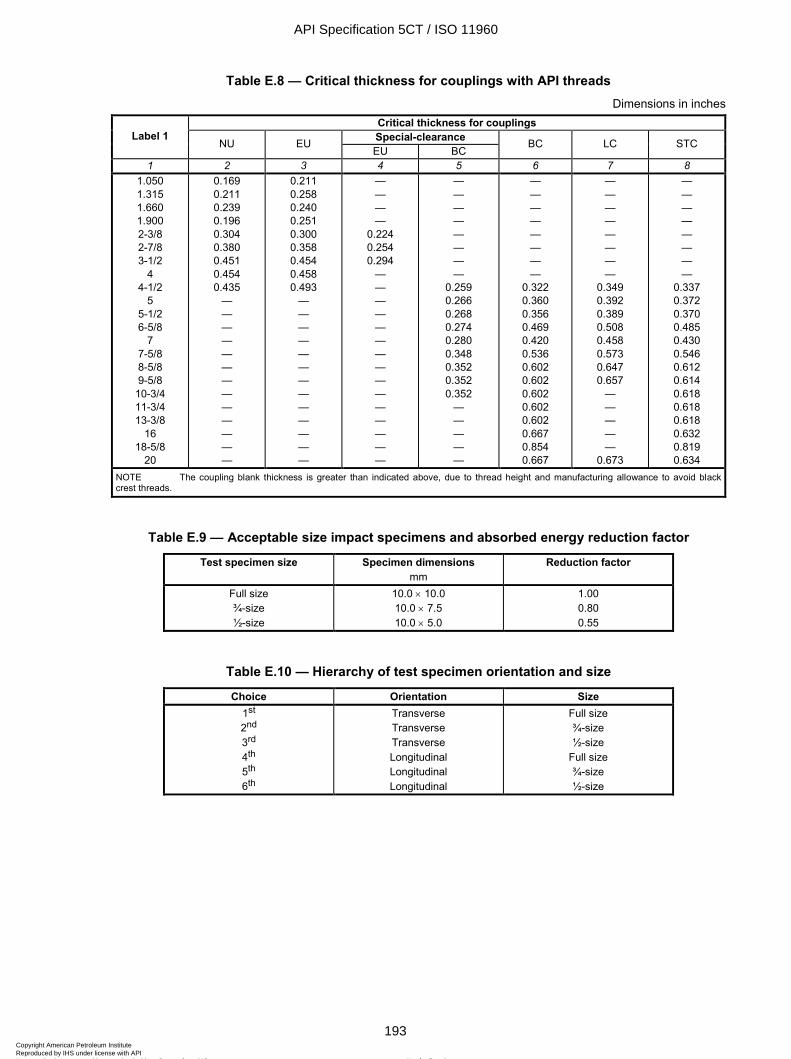
ISO 11960:2004(E)
© ISO 2004 – All rights reserved 193
Table E.8 — Critical thickness for couplings with API threads Dimensions in inches
Critical thickness for couplings Special-clearance Label 1
NU EU EU BC
BC LC STC
1 2 3 4 5 6 7 8 1.050 1.315 1.660 1.900 2-3/8 2-7/8 3-1/2
4 4-1/2
5 5-1/2 6-5/8
7 7-5/8 8-5/8 9-5/8
10-3/4 11-3/4 13-3/8
16 18-5/8
20
0.169 0.211 0.239 0.196 0.304 0.380 0.451 0.454 0.435
— — — — — — — — — — — — —
0.211 0.258 0.240 0.251 0.300 0.358 0.454 0.458 0.493
— — — — — — — — — — — — —
— — — —
0.224 0.254 0.294
— — — — — — — — — — — — — — —
— — — — — — — —
0.259 0.266 0.268 0.274 0.280 0.348 0.352 0.352 0.352
— — — — —
— — — — — — — —
0.322 0.360 0.356 0.469 0.420 0.536 0.602 0.602 0.602 0.602 0.602 0.667 0.854 0.667
— — — — — — — —
0.349 0.392 0.389 0.508 0.458 0.573 0.647 0.657
— — — — —
0.673
— — — — — — — —
0.337 0.372 0.370 0.485 0.430 0.546 0.612 0.614 0.618 0.618 0.618 0.632 0.819 0.634
NOTE The coupling blank thickness is greater than indicated above, due to thread height and manufacturing allowance to avoid black crest threads.
Table E.9 — Acceptable size impact specimens and absorbed energy reduction factor
Test specimen size Specimen dimensions mm
Reduction factor
Full size ¾-size ½-size
10.0 × 10.0 10.0 × 7.5 10.0 × 5.0
1.00 0.80 0.55
Table E.10 — Hierarchy of test specimen orientation and size
Choice Orientation Size 1st 2nd 3rd 4th
5th
6th
Transverse Transverse Transverse Longitudinal Longitudinal Longitudinal
Full size ¾-size ½-size
Full size ¾-size ½-size
API Specification 5CT / ISO 11960
193Copyright American Petroleum Institute Reproduced by IHS under license with API
Not for ResaleNo reproduction or networking permitted without license from IHS
--`,,,```-`-`,,`,,`,`,,`---
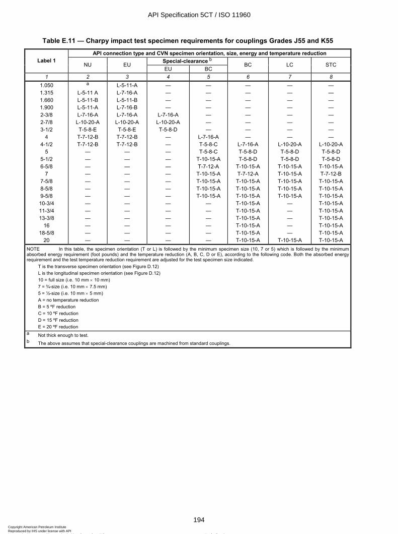
ISO 11960:2004(E)
194 © ISO 2004 – All rights reserved
Table E.11 — Charpy impact test specimen requirements for couplings Grades J55 and K55
API connection type and CVN specimen orientation, size, energy and temperature reduction Special-clearance b Label 1
NU EU EU BC
BC LC STC
1 2 3 4 5 6 7 8 1.050 1.315 1.660 1.900 2-3/8 2-7/8 3-1/2
4 4-1/2
5 5-1/2 6-5/8
7 7-5/8 8-5/8 9-5/8 10-3/4 11-3/4 13-3/8
16 18-5/8
20
a
L-5-11 A L-5-11-B L-5-11-A L-7-16-A
L-10-20-A T-5-8-E T-7-12-B T-7-12-B
— — — — — — — — — — — — —
L-5-11-A L-7-16-A L-5-11-B L-7-16-B L-7-16-A
L-10-20-A T-5-8-E T-7-12-B T-7-12-B
— — — — — — — — — — — — —
— — — —
L-7-16-A L-10-20-A T-5-8-D
— — — — — — — — — — — — — — —
— — — — — — —
L-7-16-A T-5-8-C T-5-8-C
T-10-15-A T-7-12-A T-10-15-A T-10-15-A T-10-15-A T-10-15-A
— — — — — —
— — — — — — — —
L-7-16-A T-5-8-D T-5-8-D
T-10-15-A T-7-12-A T-10-15-A T-10-15-A T-10-15-A T-10-15-A T-10-15-A T-10-15-A T-10-15-A T-10-15-A T-10-15-A
— — — — — — — —
L-10-20-A T-5-8-D T-5-8-D
T-10-15-A T-10-15-A T-10-15-A T-10-15-A T-10-15-A
— — — — —
T-10-15-A
— — — — — — — —
L-10-20-A T-5-8-D T-5-8-D
T-10-15-A T-7-12-B
T-10-15-A T-10-15-A T-10-15-A T-10-15-A T-10-15-A T-10-15-A T-10-15-A T-10-15-A T-10-15-A
NOTE In this table, the specimen orientation (T or L) is followed by the minimum specimen size (10, 7 or 5) which is followed by the minimum absorbed energy requirement (foot pounds) and the temperature reduction (A, B, C, D or E), according to the following code. Both the absorbed energy requirement and the test temperature reduction requirement are adjusted for the test specimen size indicated.
T is the transverse specimen orientation (see Figure D.12) L is the longitudinal specimen orientation (see Figure D.12) 10 = full size (i.e. 10 mm × 10 mm) 7 = ¾-size (i.e. 10 mm × 7.5 mm) 5 = ½-size (i.e. 10 mm × 5 mm) A = no temperature reduction B = 5 ºF reduction C = 10 ºF reduction D = 15 ºF reduction E = 20 ºF reduction
a Not thick enough to test. b The above assumes that special-clearance couplings are machined from standard couplings.
API Specification 5CT / ISO 11960
194Copyright American Petroleum Institute Reproduced by IHS under license with API
Not for ResaleNo reproduction or networking permitted without license from IHS
--`,,,```-`-`,,`,,`,`,,`---

ISO 11960:2004(E)
© ISO 2004 – All rights reserved 195
Table E.12 — Charpy impact test specimen requirements for couplings Grade L80 all types
API connection type and CVN specimen orientation, size and energy Special-clearance b Label 1
NU EU EU BC
BC LC STC
1 2 3 4 5 6 7 8 1.050 1.315 1.660 1.900 2-3/8 2-7/8 3-1/2
4 4-1/2
5 5-1/2 6-5/8
7 7-5/8 8-5/8 9-5/8 10-3/4 11-3/4 13-3/8
16 18-5/8
20
a
L-5-16 L-5-16 L-5-16 L-7-24 L-10-30 T-5-8
T-7-12 T-7-12
— — — — — — — — — — — — —
L-5-16 L-7-24 L-5-16 L-7-24 L-7-24 L-10-30 T-5-8
T-7-12 T-7-12
— — — — — — — — — — — — —
— — — —
L-7-24 L-10-30 T-5-8
— — — — — — — — — — — — — — —
— — — — — — — —
L-7-24 T-5-8 T-5-8
T-10-15 T-7-12
T-10-15 T-10-15 T-10-15 T-10-15
— — — — —
— — — — — — — —
L-7-24 T-5-8 T-5-8
T-10-15 T-7-12
T-10-15 T-10-15 T-10-15 T-10-15 T-10-15 T-10-15 T-10-16 T-10-18 T-10-16
— — — — — — — —
L-10-30 T-5-8 T-5-8
T-10-15 T-10-15 T-10-15 T-10-15 T-10-16
— — — — —
T-10-16
— — — — — — — — — — — — — — — —
T-10-15 T-10-15 T-10-15 T-10-15 T-10-18 T-10-15
NOTE In this table, the specimen orientation (T or L) is followed by the minimum specimen size (10, 7 or 5) which is followed by the minimum absorbed energy requirement (foot pounds) according to the following code. The absorbed energy requirement is adjusted for the test specimen size indicated.
T is the transverse specimen orientation (see Figure D.12) L is the longitudinal specimen orientation (see Figure D.12) 10 = full size (i.e. 10 mm × 10 mm) 7 = ¾-size (i.e. 10 mm × 7.5 mm) 5 = ½-size (i.e. 10 mm × 5 mm)
a Not thick enough to test. b The above assumes that special-clearance couplings are machined from standard couplings.
API Specification 5CT / ISO 11960
195Copyright American Petroleum Institute Reproduced by IHS under license with API
Not for ResaleNo reproduction or networking permitted without license from IHS
--`,,,```-`-`,,`,,`,`,,`---
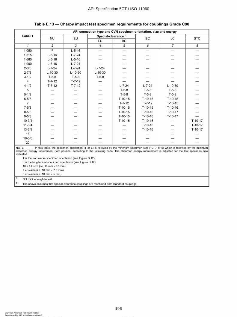
ISO 11960:2004(E)
196 © ISO 2004 – All rights reserved
Table E.13 — Charpy impact test specimen requirements for couplings Grade C90
API connection type and CVN specimen orientation, size and energy Special-clearance b Label 1
NU EU EU BC
BC LC STC
1 2 3 4 5 6 7 8 1.050 1.315 1.660 1.900 2-3/8 2-7/8 3-1/2
4 4-1/2
5 5-1/2 6-5/8
7 7-5/8 8-5/8 9-5/8 10-3/4 11-3/4 13-3/8
16 18-5/8
20
a
L-5-16 L-5-16 L-5-16 L-7-24 L-10-30 T-5-8
T-7-12 T-7-12
— — — — — — — — — — — — —
L-5-16 L-7-24 L-5-16 L-7-24 L-7-24 L-10-30 T-5-8
T-7-12 T-7-12
— — — — — — — — — — — — —
— — — —
L-7-24 L-10-30 T-5-8
— — — — — — — — — — — — — — —
— — — — — — — —
L-7-24 T-5-8 T-5-8
T-10-15 T-7-12
T-10-15 T-10-15 T-10-15 T-10-15
— — — — —
— — — — — — — —
L-7-24 T-5-8 T-5-8
T-10-15 T-7-12
T-10-15 T-10-16 T-10-16 T-10-16 T-10-16 T-10-16
— — —
— — — — — — — —
L-10-30 T-5-8 T-5-8
T-10-15 T-10-15 T-10-16 T-10-17 T-10-17
— — — — — —
— — — — — — — — — — — — — — — —
T-10-17 T-10-17 T-10-17
— — —
NOTE In this table, the specimen orientation (T or L) is followed by the minimum specimen size (10, 7 or 5) which is followed by the minimum absorbed energy requirement (foot pounds) according to the following code. The absorbed energy requirement is adjusted for the test specimen size indicated.
T is the transverse specimen orientation (see Figure D.12) L is the longitudinal specimen orientation (see Figure D.12) 10 = full size (i.e. 10 mm × 10 mm) 7 = ¾-size (i.e. 10 mm × 7.5 mm) 5 = ½-size (i.e. 10 mm × 5 mm)
a Not thick enough to test. b The above assumes that special-clearance couplings are machined from standard couplings.
API Specification 5CT / ISO 11960
196Copyright American Petroleum Institute Reproduced by IHS under license with API
Not for ResaleNo reproduction or networking permitted without license from IHS
--`,,,```-`-`,,`,,`,`,,`---
ISO 11960:2004(E)
© ISO 2004 – All rights reserved 197
Table E.14 — Charpy impact test specimen requirements for couplings — Grades N80 Type 1, N80Q, C95 and T95
API connection type and CVN specimen orientation, size and energy Special-clearance b Label 1
NU EU EU BC
BC LC STC
1 2 3 4 5 6 7 8 1.050 1.315 1.660 1.900 2-3/8 2-7/8 3-1/2
4 4-1/2
5 5-1/2 6-5/8
7 7-5/8 8-5/8 9-5/8 10-3/4 11-3/4 13-3/8
16 18-5/8
20
a
L-5-16 L-5-16 L-5-16 L-7-24
L-10-30 T-5-8 T-7-12 T-7-12
— — — — — — — — — — — — —
L-5-16 L-7-24 L-5-16 L-7-24 L-7-24
L-10-30 T-5-8 T-7-12
T-10-15 — — — — — — — — — — — — —
— — — —
L-7-24 L-10-30 T-5-8
— — — — — — — — — — — — — — —
— — — — — — — —
L-7-24 T-5-8 T-5-8
T-10-15 T-7-12
T-10-15 T-10-15 T-10-15 T-10-15
— — — — —
— — — — — — — —
L-7-24 T-5-8 T-5-8
T-10-15 T-7-12 T-10-16 T-10-17 T-10-17 T-10-17 T-10-17 T-10-17
— — —
— — — — — — — —
L-10-30 T-5-8 T-5-8
T-10-16 T-10-15 T-10-17 T-10-18 T-10-18
— — — — — —
— — — — — — — — — — — — — — — —
T-10-17 T-10-17 T-10-17
— — —
NOTE In this table, the specimen orientation (T or L) is followed by the minimum specimen size (10, 7 or 5) which is followed by the minimum absorbed energy requirement (foot pounds) according to the following code. The absorbed energy requirement is adjusted for the test specimen size indicated.
T is the transverse specimen orientation (see Figure D.12) L is the longitudinal specimen orientation (see Figure D.12) 10 = full size (i.e. 10 mm × 10 mm) 7 = ¾-size (i.e. 10 mm × 7.5 mm) 5 = ½-size (i.e. 10 mm × 5 mm)
a Not thick enough to test. b The above assumes that special-clearance couplings are machined from standard couplings.
API Specification 5CT / ISO 11960
197Copyright American Petroleum Institute Reproduced by IHS under license with API
Not for ResaleNo reproduction or networking permitted without license from IHS
--`,,,```-`-`,,`,,`,`,,`---

ISO 11960:2004(E)
198 © ISO 2004 – All rights reserved
Table E.15 — Charpy impact test specimen requirements for couplings Grade P110
API connection type and CVN specimen orientation, size and energy Special-clearance b Label 1
NU EU EU BC
BC LC STC
1 2 3 4 5 6 7 8 1.050 1.315 1.660 1.900 2-3/8 2-7/8 3-1/2
4 4-1/2
5 5-1/2 6-5/8
7 7-5/8 8-5/8 9-5/8 10-3/4 11-3/4 13-3/8
16 18-5/8
20
a
L-5-16 L-5-16 L-5-16 L-7-25
L-10-34 T-5-10 T-7-15 T-7-14
— — — — — — — — — — — — —
L-5-16 L-7-24 L-5-16 L-7-24 L-7-25
L-10-33 T-5-10 T-7-15 T-7-15
— — — — — — — — — — — — —
— — — —
L-7-24 L-10-30 T-5-8
— — — — — — — — — — — — — — —
— — — — — — — —
L-7-24 T-5-8 T-5-8
T-10-15 T-7-12
T-10-16 T-10-16 T-10-16 T-10-16
— — — — —
— — — — — — — —
L-7-26 T-5-9 T-5-9
T-10-19 T-7-14 T-10-20 T-10-22 T-10-22 T-10-22 T-10-22 T-10-22
— — —
-— — — — — — — —
L-10-33 T-5-9 T-5-9
T-10-20 T-10-19 T-10-21 T-10-23 T-10-23
— — — — — —
— — — — — — — — — — — — — — — —
T-10-22 T-10-22 T-10-22
— — —
NOTE In this table, the specimen orientation (T or L) is followed by the minimum specimen size (10, 7 or 5) which is followed by the minimum absorbed energy requirement (foot pounds) according to the following code. The absorbed energy requirement is adjusted for the test specimen size indicated.
T is the transverse specimen orientation (see Figure D.12) L is the longitudinal specimen orientation (see Figure D.12) 10 = full size (i.e. 10 mm × 10 mm) 7 = ¾-size (i.e. 10 mm × 7.5 mm) 5 = ½-size (i.e. 10 mm × 5 mm)
a Not thick enough to test. b The above assumes that special-clearance couplings are machined from standard couplings.
API Specification 5CT / ISO 11960
198Copyright American Petroleum Institute Reproduced by IHS under license with API
Not for ResaleNo reproduction or networking permitted without license from IHS
--`,,,```-`-`,,`,,`,`,,`---
ISO 11960:2004(E)
© ISO 2004 – All rights reserved 199
Table E.16 — Charpy impact test specimen requirements for couplings Grade Q125
API connection type and CVN specimen orientation, size and energy Special-clearance a Label 1
BC BC LC STC
1 2 3 4 5 4-1/2
5 5-1/2 6-5/8
7 7-5/8 8-5/8 9-5/8 10-3/4 11-3/4 13-3/8
16 18-5/8
20
L-7-25 T-5-9 T-5-9
T-10-16 T-7-13
T-10-18 T-10-18 T-10-18 T-10-18
— — — — —
L-7-27 T-5-10 T-5-10
T-10-20 T-7-15
T-10-22 T-10-23 T-10-23 T-10-23 T-10-23 T-10-23
— — —
L-10-35 T-5-10 T-5-10
T-10-21 T-10-19 T-10-23 T-10-24 T-10-25
— — — — — —
— — — — — — — —
T-10-24 T-10-24 T-10-24
— — —
NOTE In this table, the specimen orientation (T or L) is followed by the minimum specimen size (10, 7 or 5) which is followed by the minimum absorbed energy requirement (foot pounds) according to the following code. The absorbed energy requirement is adjusted for the test specimen size indicated.
T is the transverse specimen orientation (see Figure D.12) L is the longitudinal specimen orientation (see Figure D.12) 10 = full size (i.e. 10 mm × 10 mm) 7 = ¾-size (i.e. 10 mm × 7.5 mm) 5 = ½-size (i.e. 10 mm × 5 mm)
a The above assumes that special-clearance couplings are machined from standard couplings.
API Specification 5CT / ISO 11960
199Copyright American Petroleum Institute Reproduced by IHS under license with API
Not for ResaleNo reproduction or networking permitted without license from IHS
--`,,,```-`-`,,`,,`,`,,`---
ISO 11960:2004(E)
200 © ISO 2004 – All rights reserved
Table E.17 — Transverse Charpy absorbed energy requirements for couplings
Maximum critical thickness for various grades in
L80 C90 N80Q, C95, T95 P110 Q125
Minimum transverse
absorbed energy ft⋅lb
1 2 3 4 5 6 0.652 0.550 0.505 0.307 0.258 15 0.721 0.612 0.565 0.354 0.302 16 0.790 0.675 0.625 0.401 0.346 17 0.860 0.738 0.685 0.448 0.390 18 0.929 0.800 0.745 0.495 0.434 19 0.998 0.863 0.805 0.542 0.478 20 1.067 0.926 0.864 0.589 0.521 21
0.988 0.924 0.636 0.565 22 1.051 0.984 0.683 0.609 23 1.044 0.730 0.653 24 0.777 0.697 25 0.824 0.741 26 0.871 0.785 27 0.918 0.828 28 0.965 0.872 29 1.012 0.916 30 0.960 31 1.004 32
For critical thickness greater than shown above, the requirements shall be according to the equations for the wall thickness and grade.
NOTE 1 Critical thicknesses greater than shown in Table E.8 are not applicable for couplings with API threads and are shown here for information for special applications.
NOTE 2 Grade M65 is not mentioned in this table, because it is furnished with L80 Type 1 couplings.
API Specification 5CT / ISO 11960
200Copyright American Petroleum Institute Reproduced by IHS under license with API
Not for ResaleNo reproduction or networking permitted without license from IHS
--`,,,```-`-`,,`,,`,`,,`---
ISO 11960:2004(E)
© ISO 2004 – All rights reserved 201
Table E.18 — Longitudinal Charpy absorbed energy requirements for couplings
Maximum critical thickness in
L80 C90 N80Q, C95, T95 P110 Q125
Minimum longitudinal
absorbed energy ft⋅lb
1 2 3 4 5 6 0.635 0.534 0.491 0.295 0.247 30 0.669 0.565 0.520 0.319 0.269 31 0.704 0.597 0.550 0.342 0.291 32 0.738 0.628 0.580 0.366 0.313 33 0.773 0.659 0.610 0.389 0.335 34 0.808 0.691 0.640 0.413 0.357 35 0.842 0.722 0.670 0.436 0.379 36 0.877 0.753 0.700 0.460 0.401 37 0.912 0.785 0.730 0.483 0.423 38 0.946 0.816 0.760 0.507 0.445 39 0.981 0.847 0.790 0.530 0.467 40 1.015 0.879 0.819 0.554 0.489 41
0.910 0.849 0.577 0.510 42 0.941 0.879 0.601 0.532 43 0.973 0.909 0.624 0.554 44 1.004 0.939 0.648 0.576 45 0.969 0.671 0.598 46 0.999 0.695 0.620 47 1.029 0.718 0.642 48 0.742 0.664 49 0.765 0.686 50
For critical thickness greater than shown above, the requirements shall be according to the equations for the wall thickness and grade.
NOTE 1 Critical thicknesses greater than shown in Table E.8 are not applicable for couplings with API threads and are shown here for information for special applications.
NOTE 2 Grade M65 is not mentioned in this table, because it is furnished with L80 Type 1 couplings.
API Specification 5CT / ISO 11960
201Copyright American Petroleum Institute Reproduced by IHS under license with API
Not for ResaleNo reproduction or networking permitted without license from IHS
--`,,,```-`-`,,`,,`,`,,`---
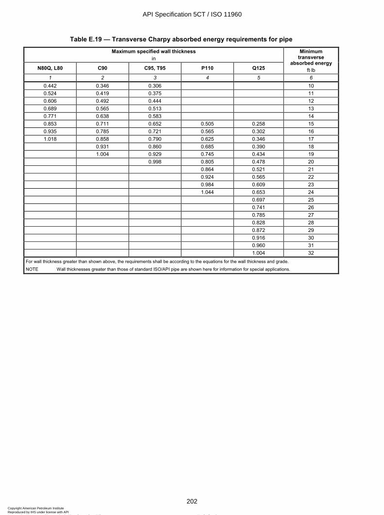
ISO 11960:2004(E)
202 © ISO 2004 – All rights reserved
Table E.19 — Transverse Charpy absorbed energy requirements for pipe
Maximum specified wall thickness in
N80Q, L80 C90 C95, T95 P110 Q125
Minimum transverse
absorbed energy ft⋅lb
1 2 3 4 5 6 0.442 0.346 0.306 10 0.524 0.419 0.375 11 0.606 0.492 0.444 12 0.689 0.565 0.513 13 0.771 0.638 0.583 14 0.853 0.711 0.652 0.505 0.258 15 0.935 0.785 0.721 0.565 0.302 16 1.018 0.858 0.790 0.625 0.346 17
0.931 0.860 0.685 0.390 18 1.004 0.929 0.745 0.434 19 0.998 0.805 0.478 20 0.864 0.521 21 0.924 0.565 22 0.984 0.609 23 1.044 0.653 24 0.697 25 0.741 26 0.785 27 0.828 28 0.872 29 0.916 30 0.960 31 1.004 32
For wall thickness greater than shown above, the requirements shall be according to the equations for the wall thickness and grade.
NOTE Wall thicknesses greater than those of standard ISO/API pipe are shown here for information for special applications.
API Specification 5CT / ISO 11960
202Copyright American Petroleum Institute Reproduced by IHS under license with API
Not for ResaleNo reproduction or networking permitted without license from IHS
--`,,,```-`-`,,`,,`,`,,`---
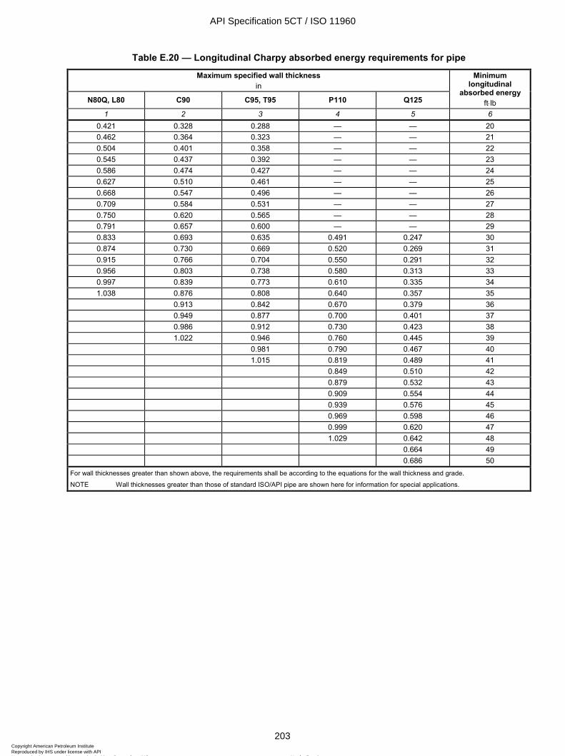
ISO 11960:2004(E)
© ISO 2004 – All rights reserved 203
Table E.20 — Longitudinal Charpy absorbed energy requirements for pipe
Maximum specified wall thickness in
N80Q, L80 C90 C95, T95 P110 Q125
Minimum longitudinal
absorbed energy ft⋅lb
1 2 3 4 5 6 0.421 0.328 0.288 — — 20 0.462 0.364 0.323 — — 21 0.504 0.401 0.358 — — 22 0.545 0.437 0.392 — — 23 0.586 0.474 0.427 — — 24 0.627 0.510 0.461 — — 25 0.668 0.547 0.496 — — 26 0.709 0.584 0.531 — — 27 0.750 0.620 0.565 — — 28 0.791 0.657 0.600 — — 29 0.833 0.693 0.635 0.491 0.247 30 0.874 0.730 0.669 0.520 0.269 31 0.915 0.766 0.704 0.550 0.291 32 0.956 0.803 0.738 0.580 0.313 33 0.997 0.839 0.773 0.610 0.335 34 1.038 0.876 0.808 0.640 0.357 35
0.913 0.842 0.670 0.379 36 0.949 0.877 0.700 0.401 37 0.986 0.912 0.730 0.423 38 1.022 0.946 0.760 0.445 39 0.981 0.790 0.467 40 1.015 0.819 0.489 41 0.849 0.510 42 0.879 0.532 43 0.909 0.554 44 0.939 0.576 45 0.969 0.598 46 0.999 0.620 47 1.029 0.642 48 0.664 49 0.686 50
For wall thicknesses greater than shown above, the requirements shall be according to the equations for the wall thickness and grade.
NOTE Wall thicknesses greater than those of standard ISO/API pipe are shown here for information for special applications.
API Specification 5CT / ISO 11960
203Copyright American Petroleum Institute Reproduced by IHS under license with API
Not for ResaleNo reproduction or networking permitted without license from IHS
--`,,,```-`-`,,`,,`,`,,`---
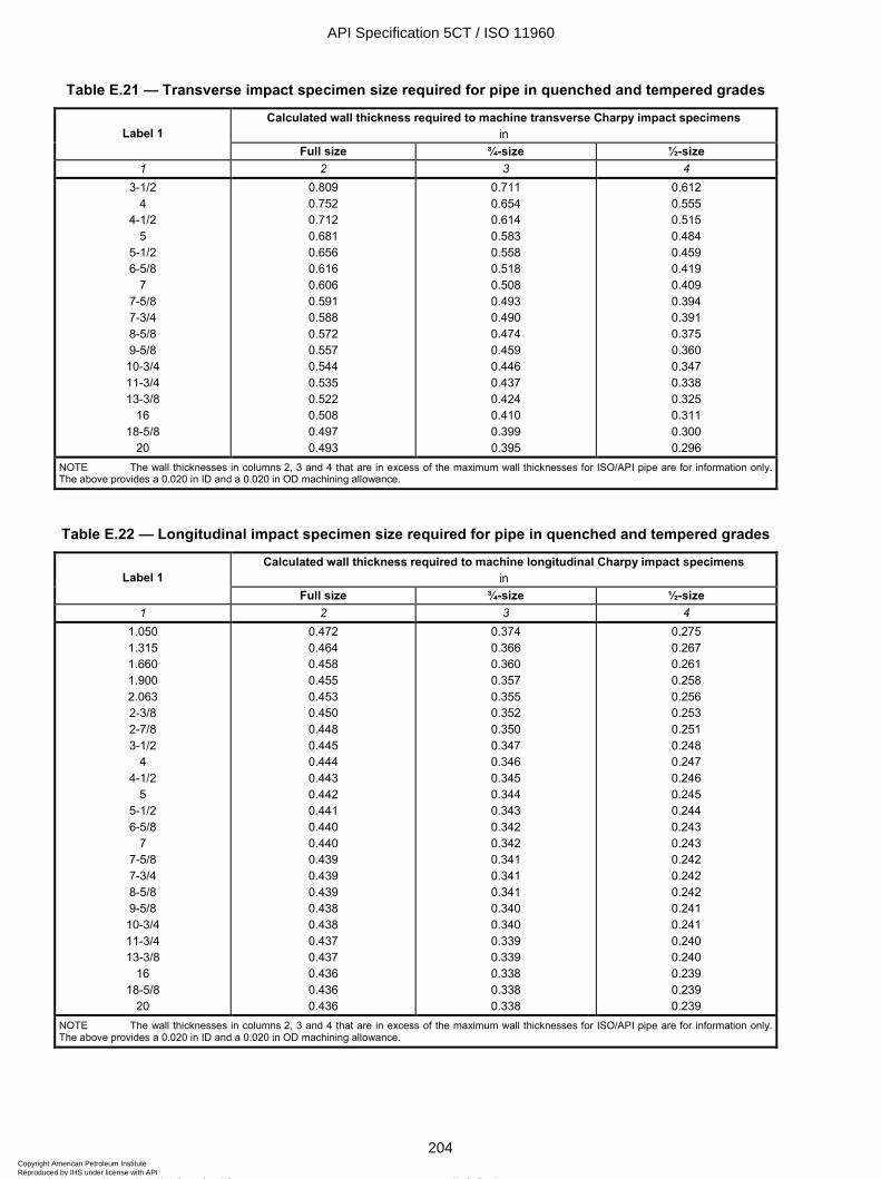
ISO 11960:2004(E)
204 © ISO 2004 – All rights reserved
Table E.21 — Transverse impact specimen size required for pipe in quenched and tempered grades
Calculated wall thickness required to machine transverse Charpy impact specimens in Label 1
Full size ¾-size ½-size 1 2 3 4
3-1/2 4
4-1/2 5
5-1/2 6-5/8
7 7-5/8 7-3/4 8-5/8 9-5/8 10-3/4 11-3/4 13-3/8
16 18-5/8
20
0.809 0.752 0.712 0.681 0.656 0.616 0.606 0.591 0.588 0.572 0.557 0.544 0.535 0.522 0.508 0.497 0.493
0.711 0.654 0.614 0.583 0.558 0.518 0.508 0.493 0.490 0.474 0.459 0.446 0.437 0.424 0.410 0.399 0.395
0.612 0.555 0.515 0.484 0.459 0.419 0.409 0.394 0.391 0.375 0.360 0.347 0.338 0.325 0.311 0.300 0.296
NOTE The wall thicknesses in columns 2, 3 and 4 that are in excess of the maximum wall thicknesses for ISO/API pipe are for information only. The above provides a 0.020 in ID and a 0.020 in OD machining allowance.
Table E.22 — Longitudinal impact specimen size required for pipe in quenched and tempered grades
Calculated wall thickness required to machine longitudinal Charpy impact specimens in Label 1
Full size ¾-size ½-size 1 2 3 4
1.050 1.315 1.660 1.900 2.063 2-3/8 2-7/8 3-1/2
4 4-1/2
5 5-1/2 6-5/8
7 7-5/8 7-3/4 8-5/8 9-5/8 10-3/4 11-3/4 13-3/8
16 18-5/8
20
0.472 0.464 0.458 0.455 0.453 0.450 0.448 0.445 0.444 0.443 0.442 0.441 0.440 0.440 0.439 0.439 0.439 0.438 0.438 0.437 0.437 0.436 0.436 0.436
0.374 0.366 0.360 0.357 0.355 0.352 0.350 0.347 0.346 0.345 0.344 0.343 0.342 0.342 0.341 0.341 0.341 0.340 0.340 0.339 0.339 0.338 0.338 0.338
0.275 0.267 0.261 0.258 0.256 0.253 0.251 0.248 0.247 0.246 0.245 0.244 0.243 0.243 0.242 0.242 0.242 0.241 0.241 0.240 0.240 0.239 0.239 0.239
NOTE The wall thicknesses in columns 2, 3 and 4 that are in excess of the maximum wall thicknesses for ISO/API pipe are for information only. The above provides a 0.020 in ID and a 0.020 in OD machining allowance.
API Specification 5CT / ISO 11960
204Copyright American Petroleum Institute Reproduced by IHS under license with API
Not for ResaleNo reproduction or networking permitted without license from IHS
--`,,,```-`-`,,`,,`,`,,`---
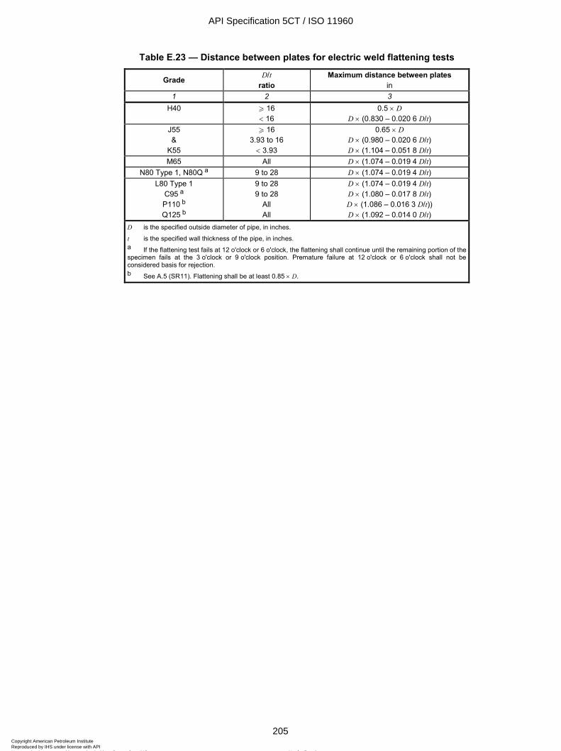
ISO 11960:2004(E)
© ISO 2004 – All rights reserved 205
Table E.23 — Distance between plates for electric weld flattening tests
Grade D/t ratio
Maximum distance between plates in
1 2 3 H40 W 16
< 16 0.5 × D
D × (0.830 – 0.020 6 D/t) J55 &
K55
W 16 3.93 to 16 < 3.93
0.65 × D D × (0.980 – 0.020 6 D/t) D × (1.104 – 0.051 8 D/t)
M65 All D × (1.074 – 0.019 4 D/t) N80 Type 1, N80Q a 9 to 28 D × (1.074 – 0.019 4 D/t)
L80 Type 1 C95 a P110 b Q125 b
9 to 28 9 to 28
All All
D × (1.074 – 0.019 4 D/t) D × (1.080 – 0.017 8 D/t) D × (1.086 – 0.016 3 D/t)) D × (1.092 – 0.014 0 D/t)
D is the specified outside diameter of pipe, in inches.
t is the specified wall thickness of the pipe, in inches. a If the flattening test fails at 12 o'clock or 6 o'clock, the flattening shall continue until the remaining portion of the specimen fails at the 3 o'clock or 9 o'clock position. Premature failure at 12 o'clock or 6 o'clock shall not be considered basis for rejection. b See A.5 (SR11). Flattening shall be at least 0.85 × D.
API Specification 5CT / ISO 11960
205Copyright American Petroleum Institute Reproduced by IHS under license with API
Not for ResaleNo reproduction or networking permitted without license from IHS
--`,,,```-`-`,,`,,`,`,,`---
ISO 11960:2004(E)
206 © ISO 2004 – All rights reserved
Table E.24 — Dimensions and masses for standard casing and for casing threaded with API round thread, buttress thread and extreme-line connections
Calculated mass c em , mass gain or loss due to end finishing d
lb Labels a Outside diameter
Nominal linear mass
T&C b, c
Wall thick-ness
Inside diam-eter
Drift diam-eter
Plain end
Round thread Buttress thread Extreme-line
1 2 D in lb/ft
t in
d in in
wpe lb/ft
Short Long Reg. OD SCC Standard Optional
1 2 3 4 5 6 7 8 9 10 11 12 13 14 4-1/2 4-1/2 4-1/2 4-1/2 4-1/2
9.50 10.50 11.60 13.50 15.10
4.500 4.500 4.500 4.500 4.500
9.50 10.50 11.60 13.50 15.10
0.205 0.224 0.250 0.290 0.337
4.090 4.052 4.000 3.920 3.826
3.965 3.927 3.875 3.795 3.701
9.41 10.24 11.36 13.05 15.00
4.20 3.80 3.40 — —
— —
3.80 3.20 2.80
— 5.00 4.60 4.00 3.20
— 2.56 2.16 1.56 0.76
— — — — —
— — — — —
5 5 5 5 5 5 5
11.50 13.00 15.00 18.00 21.40 23.20 24.10
5.000 5.000 5.000 5.000 5.000 5.000 5.000
11.50 13.00 15.00 18.00 21.40 23.20 24.10
0.220 0.253 0.296 0.362 0.437 0.478 0.500
4.560 4.494 4.408 4.276 4.126 4.044 4.000
4.435 4.369 4.283 4.151 4.001 3.919 3.875
11.24 12.84 14.88 17.95 21.32 23.11 24.05
5.40 4.80 4.20 — — — —
— 5.80 5.20 4.20 2.95 2.30 1.95
— 6.60 5.80 4.40 2.46 2.05 1.24
— 2.42 1.62 0.22 -1.72 -2.09 -2.94
— —
4.60 1.40 — — —
— — — — — — —
5-1/2 5-1/2 5-1/2 5-1/2 5-1/2 5-1/2 5-1/2 5-1/2 5-1/2 5-1/2 5-1/2 5-1/2
14.00 15.50 17.00 20.00 23.00 26.80 29.70 32.60 35.30 38.00 40.50 43.10
5.500 5.500 5.500 5.500 5.500 5.500 5.500 5.500 5.500 5.500 5.500 5.500
14.00 15.50 17.00 20.00 23.00 26.80 29.70 32.60 35.30 38.00 40.50 43.10
0.244 0.275 0.304 0.361 0.415 0.500 0.562 0625 0.687 0.750 0.812 0.875
5.012 4.950 4.892 4.778 4.670 4.500 4.376 4.250 4.126 4.000 3.876 3.750
4.887 4.825 4.767 4.653 4.545 4.375 4.251 4.125 4.001 3.875 3.751 3.625
13.71 15.36 16.89 19.83 22.56 26.72 29.67 32.57 35.35 38.08 40.69 43.26
5.40 4.80 4.40 — — — — — — — — —
— 5.80 5.40 4.40 3.20 — — — — — — —
— 6.40 5.80 4.60 3.40 — — — — — — —
— 2.10 1.50 0.30 -0.90
— — — — — — —
— 5.80 4.80 1.40 0.00 — — — — — — —
— 4.20 3.20 -0.20 -1.60
— — — — — — —
6-5/8 6-5/8 6-5/8 6-5/8
20.00 24.00 28.00 32.00
6.625 6.625 6.625 6.625
20.00 24.00 28.00 32.00
0.288 0.352 0.417 0.475
6.049 5.921 5.791 5.675
5.924 5.796 5.666 5.550
19.51 23.60 27.67 31.23
11.009.60 — —
13.60 12.00 10.20 8.80
14.40 12.60 10.60 9.00
2.38 0.58 -1.42 -3.02
— 3.40 0.20 -1.40
— 1.80 -1.40 -3.00
7 7 7 7 7 7 7 7 7 7 7 7 7 7 7
17.00 20.00 23.00 23.00 26.00 29.00 32.00 32.00 35.00 38.00 42.70 46.40 50.10 53.60 57.10
7.000 7.000 7.000 7.000 7.000 7.000 7.000 7.000 7.000 7.000 7.000 7.000 7.000 7.000 7.000
17.00 20.00 23.00 23.00 26.00 29.00 32.00 32.00 35.00 38.00 42.70 46.40 50.10 53.60 57.10
0.231 0.272 0.317 0.317 0.362 0.408 0.453 0.453 0.498 0.540 0.625 0.687 0.750 0.812 0.875
6.538 6.456 6.366 6.366 6.276 6.184 6.094 6.094 6.004 5.920 5.750 5.625 5.500 5.376 5.250
6.413 6.331
6.250 e 6.241 6.151 6.059
6.000 e 5.969 5.879 5.795 5.625 5.500 5.375 5.251 5.125
16.72 19.56 22.65 22.65 25.69 28.75 31.70 31.70 34.61 37.29 42.59 46.36 50.11 53.71 57.29
10.009.40 8.00 8.00 7.20 — — — — — — — — — —
— —
10.40 10.40 9.40 8.00 6.60 6.60 5.60 4.40 — — — — —
— —
11.00 11.00 9.60 8.20 6.80 6.80 5.60 4.20 — — — — —
— —
1.60 1.60 0.20 -1.20 -2.60 -2.60 -3.80 -5.20
— — — — —
— —
6.00 6.00 2.80 0.60 -0.60 -0.60 1.00 -0.20
— — — — —
— —
4.20 4.20 1.00 -1.20 -2.40 -2.40 -1.80 -3.00
— — — — —
See notes at end of table.
API Specification 5CT / ISO 11960
206Copyright American Petroleum Institute Reproduced by IHS under license with API
Not for ResaleNo reproduction or networking permitted without license from IHS
--`,,,```-`-`,,`,,`,`,,`---
ISO 11960:2004(E)
© ISO 2004 – All rights reserved 207
Table E.24 (continued)
Calculated mass c em , mass gain or loss due to end finishing d
lb Labels a Outside diameter
Nominal linear mass
T&C b, c
Wall thick-ness
Inside diam-eter
Drift diam-eter
Plain end
Round thread Buttress thread Extreme-line
1 2 D in lb/ft
t in
d in in
wpe lb/ft
Short Long Reg. OD SCC Standard Optional
1 2 3 4 5 6 7 8 9 10 11 12 13 14 7-5/8 7-5/8 7-5/8 7-5/8 7-5/8 7-5/8 7-5/8 7-5/8 7-5/8 7-5/8
24.00 26.20 29.70 33.70 39.00 42.80 45.30 47.10 51.20 55.30
7.625 7.625 7.625 7.625 7.625 7.625 7.625 7.625 7.625 7.625
24.00 26.40 29.70 33.70 39.00 42.80 45.30 47.10 51.20 55.30
0.300 0.328 0.375 0.430 0.500 0.562 0.595 0.625 0.687 0.750
7.025 6.969 6.875 6.765 6.625 6.501 6.435 6.375 6.251 6.125
6.900 6.844 6.750 6.640 6.500 6.376 6.310 6.250 6.126 6.000
23.49 25.59 29.06 33.07 38.08 42.43 44.71 46.77 50.95 55.12
15.8015.20
— — — — — — — —
— 19.00 17.40 15.80 13.60 12.01 11.04 10.16
— —
— 20.60 18.80 17.00 14.60 11.39 11.04 9.23 — —
— 6.21 4.41 2.61 0.21 -3.01 -3.36 -5.17
— —
— 6.40 2.60 0.00 -2.20
— — — — —
— 4.00 0.20 -2.40 -4.60
— — — — —
7-3/4 7-3/4
46.10 46.10
7.750 7.750
46.10 46.10
0.595 0.595
6.560 6.560
6.500 e 6.435
45.51 45.51
— —
— —
— —
— —
— —
— —
8-5/8 8-5/8 8-5/8 8-5/8 8-5/8 8-5/8 8-5/8 8-5/8 8-5/8
24.00 28.00 32.00 32.00 36.00 40.00 40.00 44.00 49.00
8.625 8.625 8.625 8.625 8.625 8.625 8.625 8.625 8.625
24.00 28.00 32.00 32.00 36.00 40.00 40.00 44.00 49.00
0.264 0.304 0.352 0.352 0.400 0.450 0.450 0.500 0.557
8.097 8.017 7.921 7.921 7.825 7.725 7.725 7.625 7.511
7.972 7.892
7.875 e 7.796 7.700
7.625 e 7.600 7.500 7.286
23.60 27.04 31.13 31.13 35.17 39.33 39.33 43.43 48.04
23.6022.2020.8020.8019.40
— — — —
— —
27.60 27.60 25.60 23.80 23.80 21.80 19.60
— —
28.30 28.20 26.20 24.20 24.20 22.20 19.80
— —
6.03 6.03 4.03 2.03 2.03 0.03 -2.37
— —
13.20 13.20 7.60 4.00 4.00 1.60 -0.80
— —
8.80 8.80 4.20 0.60 0.60 -1.80 -4.20
9-5/8 9-5/8 9-5/8 9-5/8 9-5/8 9-5/8 9-5/8 9-5/8 9-5/8 9-5/8 9-5/8 9-5/8 9-5/8 9-5/8
32.30 36.00 40.00 40.00 43.50 47.00 53.50 53.50 58.40 58.40 59.40 64.90 70.30 75.60
9.625 9.625 9.625 9.625 9.625 9.625 9.625 9.625 9.625 9.625 9.625 9.625 9.625 9.625
32.30 36.00 40.00 40.00 43.50 47.00 53.50 53.50 58.40 58.40 59.40 64.90 70.30 75.60
0.312 0.352 0.395 0.395 0.435 0.472 0.545 0.545 0.595 0.595 0.609 0.672 0.734 0.797
9.001 8.921 8.835 8.835 8.755 8.681 8.535 8.535 8.435 8.435 8.407 8.281 8.157 8.031
8.845 8.765
8.750 e 8.679 8.599 8.525
8.500 e 8.379
8.375 e 8.279 8.251 8.125 8.001 7.875
31.06 34.89 38.97 38.97 42.73 46.18 52.90 52.90 57.44 57.44 58.70 64.32 69.76 75.21
24.4023.0021.4021.40
— — — — — — — — — —
— 32.00 30.00 30.00 28.20 26.60 23.40 23.40 21.50 21.50
— — — —
— 31.00 29.00 29.00 27.20 25.60 22.40 22.40 20.13 20.13
— — — —
— 6.48 4.48 4.48 2.68 1.08 -2.12 -2.12 -4.40 -4.40
— — — —
— —
10.60 10.60 5.40 2.20 -1.20 -1.20
— — — — — —
— —
7.20 7.20 2.00 -1.20 -4.60 -4.60
— — — — — —
10-3/4 10-3/4 10-3/4 10-3/4 10-3/4 10-3/4 10-3/4 10-3/4 10-3/4 10-3/4 10-3/4 10-3/4
32.75 40.50 45.50 45.50 51.00 55.50 55.50 60.70 65.70 73.20 79.20 85.30
10.750 10.750 10.750 10.750 10.750 10.750 10.750 10.750 10.750 10.750 10.750 10.750
32.75 40.50 45.50 45.50 51.00 55.50 55.50 60.70 65.70 73.20 79.20 85.30
0.279 0.350 0.400 0.400 0.450 0.495 0.495 0.545 0.595 0.672 0.734 0.797
10.192 10.050 9.950 9.950 9.850 9.760 9.760 9.660 9.560 9.406 9.282 9.156
10.036 9.894
9.875 e 9.794 9.694
9.625 e 9.604 9.504 9.404 9.250 9.126 9.000
31.23 38.91 44.26 44.26 49.55 54.26 54.26 59.45 64.59 72.40 78.59 84.80
29.0026.4024.4024.4022.6020.8020.8018.8016.80
— — —
— — — — — — — — — — — —
— 34.40 31.80 31.80 29.40 27.00 27.00 24.40 22.00
— — —
— 7.21 4.61 4.61 2.21 -0.19 -0.19
— — — — —
— —
21.20 21.20 18.40 15.80 15.80 13.00
— — — —
— — — — — — — — — — — —
See notes at end of table.
API Specification 5CT / ISO 11960
207Copyright American Petroleum Institute Reproduced by IHS under license with API
Not for ResaleNo reproduction or networking permitted without license from IHS
--`,,,```-`-`,,`,,`,`,,`---
ISO 11960:2004(E)
208 © ISO 2004 – All rights reserved
Table E.24 (continued)
Calculated mass c em , mass gain or loss due to end finishing d
lb Labels a Outside diameter
Nominal linear mass
T&C b, c
Wall thick-ness
Inside diam-eter
Drift diam-eter
Plain end
Round thread Buttress thread Extreme-line
1 2 D in lb/ft
t in
d in in
wpe lb/ft
Short Long Reg. OD SCC Standard Optional
1 2 3 4 5 6 7 8 9 10 11 12 13 14 11-3/4 11-3/4 11-3/4 11-3/4 11-3/4 11-3/4 11-3/4 11-3/4 11-3/4
42.00 42.00 47.00 54.00 60.00 60.00 65.00 65.00 71.00
11.750 11.750 11.750 11.750 11.750 11.750 11.750 11.750 11.750
42.00 42.00 47.00 54.00 60.00 60.00 65.00 65.00 71.00
0.333 0.333 0.375 0.435 0.489 0.489 0.534 0.534 0.582
11.084 11.084 11.000 10.880 10.772 10.772 10.682 10.682 10.586
11.000 e
10.928 10.844 10.724
10.625 e
10.616 10.625 e
10.526 10.430
40.64 40.64 45.60 52.62 58.87 58.87 64.03 64.03 69.48
29.6029.6027.6025.0022.6022.60
— — —
— — — — — — — — —
— —
35.80 32.40 29.60 29.60
— — —
— — — — — — — — —
— — — — — — — — —
— — — — — — — — —
13-3/8 13-3/8 13-3/8 13-3/8 13-3/8 13-3/8
48.00 54.50 61.00 68.00 72.00 72.00
13.375 13.375 13.375 13.375 13.375 13.375
48.00 54.50 61.00 68.00 72.00 72.00
0.330 0.380 0.430 0.480 0.514 0.514
12.715 12.615 12.515 12.415 12.347 12.347
12.559 12.459 12.359 12.259
12.250 e
12.191
46.02 52.79 59.50 66.17 70.67 70.67
33.2030.8028.4025.8024.2024.20
— — — — — —
— 40.20 36.80 33.60 31.60 31.60
— — — — — —
— — — — — —
— — — — — —
16 16 16 16
65.00 75.00 84.00
109.00
16.000 16.000 16.000 16.000
65.00 75.00 84.00
109.00
0.375 0.438 0.495 0.656
15.250 15.124 15.010 14.688
15.062 14.936 14.822 14.500
62.64 72.86 82.05
107.60
42.6038.2034.20
—
— — — —
— 45.60 39.60
—
— — — —
— — — —
— — — —
18-5/8 87.50 18.625 87.50 0.435 17.755 17.567 84.59 73.60 — 86.40 — — — 20 20 20
94.00 106.50 133.00
20.000 20.000 20.000
94.00 106.50 133.00
0.438 0.500 0.635
19.124 19.000 18.730
18.936 18.812 18.542
91.59 104.23 131.45
47.0041.6030.00
61.20 54.80 40.60
54.80 48.40 35.20
— — —
— — —
— — —
See Figures D.1, D.2, D.3 and D.8. a Labels are for information and assistance in ordering. b Nominal linear masses, threaded and coupled (col. 4) are shown for information only. c The densities of martensitic chromium steels (L80 Types 9Cr and 13Cr) are less than those of carbon steels. The masses shown are therefore not accurate for martensitic chromium steels. A mass correction factor of 0.989 may be used. d Mass gain or loss due to end finishing. See 8.5. e Drift diameter for most common bit size. This drift diameter shall be specified on the purchase agreement and marked on the pipe. See 8.10 for drift requirements.
API Specification 5CT / ISO 11960
208Copyright American Petroleum Institute Reproduced by IHS under license with API
Not for ResaleNo reproduction or networking permitted without license from IHS
--`,,,```-`-`,,`,,`,`,,`---
ISO 11960:2004(E)
© ISO 2004 – All rights reserved 209
Table E.25 — Dimensions and masses for standard tubing and for tubing threaded with API non-upset, external upset and integral joint tubing connections
Calculated mass c
Labels a Nominal linear masses b, c
em , mass gain or loss due to end finishing d
lb 1 2
Outside dia.
Wall thick-ness
Inside dia. Plain
end External upset e
NU T&C
EU T&C
IJ D in
Non-upset T&C lb/ft
Ext. upset T&C lb/ft
Integral joint
lb/ft
t in
d in
wpe lb/ft
Non-upset Regular Special-
clear-ance
Integral joint
1 2 3 4 5 6 7 8 9 10 11 12 13 14 15 1.050 1.050
1.14 1.48
1.20 1.54
— —
1.050 1.050
1.14 1.48
1.20 1.54
— —
0.113 0.154
0.824 0.742
1.13 1.48
0.20 —
1.40 1.32
— —
— —
1.315 1.315
1.70 2.19
1.80 2.24
1.72 —
1.315 1.315
1.70 2.19
1.80 2.24
1.72 —
0.133 0.179
1.049 0.957
1.68 2.17
0.40 —
1.40 1.35
— —
0.20 —
1.660 1.660 1.660
2.09 2.30 3.03
— 2.40 3.07
2.10 2.33 —
1.660 1.660 1.660
— 2.30 3.03
— 2.40 3.07
2.10 2.33 —
0.125 0.140 0.191
1.410 1.380 1.278
2.05 2.27 3.00
— 0.80 —
— 1.60 1.50
— —
0.20
0.20 0.20 —
1.900 1.900 1.900 1.900 1.900
2.40 2.75 3.65 4.42 5.15
— 2.90 3.73 — —
2.40 2.76 — — —
1.990 1.990 1.990 1.990 1.990
— 2.75 3.65 4.42 5.15
— 2.90 3.73 — —
2.40 2.76 — — —
0.125 0.145 0.200 0.250 0.300
1.650 1.610 1.500 1.400 1.300
2.37 2.72 3.63 4.41 5.13
— 0.60 — — —
— 2.00 2.03 — —
— — — — —
0.20 0.20 — — —
2.063 2.063
3.24 4.50
— —
3.25 —
2.063 2.063
— —
— —
3.25 —
0.156 0.225
1.751 1.613
3.18 4.42
— —
— —
— —
0.20 —
2-3/8 2-3/8 2-3/8 2-3/8 2-3/8
4.00 4.60 5.80 6.60 7.35
— 4.70 5.95 —
7.45
— — — — —
2.375 2.375 2.375 2.375 2.375
4.00 4.60 5.80 6.60 7.35
— 4.70 5.95 —
7.45
— — — — —
0.167 0.190 0.254 0.295 0.336
2.041 1.995 1.867 1.785 1.703
3.94 4.44 5.76 6.56 7.32
1.60 1.60 1.40 — —
— 4.00 3.60 — —
— 2.96 2.56 — —
— — — — —
2-7/8 2-7/8 2-7/8 2-7/8 2-7/8 2-7/8
6.40 7.80 8.60 9.35 1.050 11.50
6.50 7.90 8.70 9.45 — —
— — — — —
2.875 2.875 2.875 2.875 2.875 2.875
6.40 7.80 8.60 9.35
10.50 11.50
6.50 7.90 8.70 9.45 — —
— — — — — —
0.217 0.276 0.308 0.340 0.392 0.440
2.441 2.323 2.259 2.195 2.091 1.995
6.17 7.67 8.45 9.21 10.40 11.45
3.20 2.80 2.60 — — —
5.60 5.80 5.00 — — —
3.76 3.92 3.16 — — —
— — — — — —
3-1/2 3-1/2 3-1/2 3-1/2 3-1/2 3-1/2 3-1/2
7.70 9.20 10.20 12.70 14.30 15.50 17.00
— 9.30 —
12.95 — — —
— — — — — — —
3.500 3.500 3.500 3.500 3.500 3.500 3.500
7.70 9.20
10.20 12.70 14.30 15.50 17.00
— 9.30 —
12.95 — — —
— — — — — — —
0.216 0.254 0.289 0.375 0.430 0.476 0.530
3.068 2.992 2.922 2.750 2.640 2.548 2.440
7.58 8.81 9.92 12.53 14.11 15.39 16.83
5.40 5.00 4.80 4.00 — — —
— 9.20 —
8.20 — — —
— 5.40 —
4.40 — — —
— — — — — — —
4 4 4 4 4 4
9.50 10.70 13.20 16.10 18.90 22.20
— 11.00
— — — —
— — — — — —
4.000 4.000 4.000 4.000 4.000 4.000
9.50 —
13.20 16.10 18.90 22.20
— 11.00
— — — —
— — — — — —
0.226 0.262 0.330 0.415 0.500 0.610
3.548 3.476 3.340 3.170 3.000 2.78o
9.12 10.47 12.95 15.90 18.71 22.11
6.20 — — — — —
— 10.60
— — — —
— — — — — —
— — — — — —
4-1/2 4-1/2 4-1/2 4-1/2 4-1/2 4-1/2 4-1/2
12.60 15.20 17.00 18.90 21.50 23.70 26.10
12.75 — — — — — —
— — — — — — —
4.500 4.500 4.500 4.500 4.500 4.500 4.500
12.60 15.20 17.00 18.90 21.50 23.70 26.10
12.75 — — — — — —
— — — — — — —
0.271 0.337 0.380 0.430 0.500 0.560 0.630
3.958 3.826 3.740 3.640 3.500 3.380 3.240
12.25 15.00 16.77 18.71 21.38 23.59 26.06
6.00 — — — — — —
13.20 — — — — — —
— — — — — — —
— — — — — — —
See Figures D.4, D.5 and D.7. a Labels are for information and assistance in ordering. b Nominal linear masses, threaded and coupled (Col. 6, 7 and 8) are shown for information only. c The densities of martensitic chromium (L80 Types 9Cr and 13Cr) are different from carbon steels. The masses shown are therefore not accurate for martensitic chromium steels. A mass correction factor of 0.989 may be used. d Mass gain or loss due to end finishing. See 8.5. e The length of the upset may alter the mass gain or loss due to end finishing.
API Specification 5CT / ISO 11960
209Copyright American Petroleum Institute Reproduced by IHS under license with API
Not for ResaleNo reproduction or networking permitted without license from IHS
--`,,,```-`-`,,`,,`,`,,`---
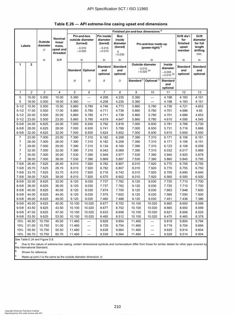
ISO 11960:2004(E)
210 © ISO 2004 – All rights reserved
Table E.26 — API extreme-line casing upset end dimensions
Finished pin-and-box dimensions a
Labels Outside diameter
D
Nominal linear mass,
upset and threaded
Pin-and-box outside diameter
(turned) 0.0100.020
-+
Pin inside diameter (bored)
0.0150.015
-+
Box inside
diameter (bored)
00.030+
Pin-and-box made-up (power-tight) b
Drift dia’r for
finished upset
member
Drift diameter for full length drifting
min.
in lb/ft in in in in in in 1 2
Standard Optional Standard
and optional
Standard and
optional
Outside diameter 0.0100.020
-+ in
Inside diameter
0.0050.010
-+ in
Standard and
optional
Standard and
optional
M M B D Standard c Optional c Standard
and optional
1 2 3 4 5 6 7 8 9 10 11 12 13 5 5
15.00 18.00
5.000 5.000
15.00 18.00
5.360 5.360
— —
4.208 4.208
4.235 4.235
5.360 5.360
— —
4.198 4.198
4.183 4.183
4.151 4.151
5-1/2 5-1/2 5-1/2 5-1/2
15.50 17.00 20.00 23.00
5.500 5.500 5.500 5.500
15.50 17.00 20.00 23.00
5.860 5.860 5.860 5.860
5.780 5.780 5.780 5.780
4.746 4.711 4.711 4.619
4.773 4.738 4.738 4.647
5.860 5.860 5.860 5.860
5.780 5.780 5.780 5.780
4.736 4.701 4.701 4.610
4.721 4.686 4.686 4.595
4.653 4.65 4.653 4.545
6-5/8 6-5/8 6-5/8
24.00 28.00 32.00
6.625 6.625 6.625
24.00 28.00 32.00
7.000 7.000 7.000
6.930 6.930 6.930
5.792 5.741 5.624
5.818 5.768 5.652
7.000 7.000 7.000
6.930 6.930 6.930
5.781 5.731 5.615
5.766 5.716 5.600
5.730 5.666 5.550
7 7 7 7 7 7
23.00 26.00 29.00 32.00 35.00 38.00
7.000 7.000 7.000 7.000 7.000 7.000
23.00 26.00 29.00 32.00 35.00 38.00
7.390 7.390 7.390 7.390 7.530 7.530
7.310 7.310 7.310 7.310 7.390 7.390
6.182 6.182 6.134 6.042 5.949 5.869
6.208 6.208 6.160 6.069 5.977 5.897
7.390 7.390 7.390 7.390 7.530 7.530
7.310 7.310 7.310 7.310 7.390 7.390
6.171 6.171 6.123 6.032 5.940 5.860
6.156 5.156 6.108 6.017 5.925 5.845
6.151 6.151 6.059 5.969 5.879 5.795
7-5/8 7-5/8 7-5/8 7-5/8
26.40 29.70 33.70 39.00
7.625 7.625 7.625 7.625
26.40 29.70 33.70 39.00
8.010 8.010 8.010 8.010
7.920 7.920 7.920 7.920
6.782 6.782 6.716 6.575
6.807 6.807 6.742 6.602
8.010 8.010 8.010 8.010
7.920 7.920 7.920 7.920
6.770 6.770 6.705 6.565
6.755 6.755 6.690 6.550
6.750 6.750 6.640 6.500
8-5/8 8-5/8 8-5/8 8-5/8 8-5/8
32.00 36.00 40.00 44.00 49.00
8.625 8.625 8.625 8.625 8.625
32.00 36.00 40.00 44.00 49.00
9.120 9.120 9.120 9.120 9.120
9.030 9.030 9.030 9.030 9.030
7.737 7.737 7.674 7.575 7.460
7.762 7.762 7.700 7.602 7.488
9.120 9.120 9.120 9.120 9.120
9.030 9.030 9.030 9.030 9.030
7.725 7.725 7.663 7.565 7.451
7.710 7.710 7.648 7.550 7.436
7.700 7.700 7.600 7.500 7.386
9-5/8 9-5/8 9-5/8 9-5/8
40.00 43.50 47.00 53.50
9.625 9.625 9.625 9.625
40.00 43.50 47.00 53.50
10.100 10.100 10.100 10.100
10.020 10.020 10.020 10.020
8.677 8.677 8.633 8.485
8.702 8.702 8.658 8.512
10.100 10.100 10.100 10.100
10.020 10.020 10.020 10.020
8.665 8.665 8.621 8.475
8.650 8.650 8.606 8.460
8.599 8.599 8.525 8.379
10¾ 10¾ 10¾ 10¾
45.50 51.00 55.50 60.70
10.750 10.750 10.750 10.750
45.50 51.00 55.50 60.70
11.460 11.460 11.460 11.460
— — — —
9.829 9.729 9.639 9.539
9.854 9.754 9.664 9.564
11.460 11.460 11.460 11.460
— — — —
9.819 9.719 9.629 9.529
9.804 9.704 9.614 9.514
9.794 9.694 9.604 9.504
See Table E.24 and Figure D.8. a Due to the nature of extreme-line casing, certain dimensional symbols and nomenclature differ from those for similar details for other pipe covered by this International Standard. b Shown for reference. c Made-up joint D is the same as the outside diameter dimension M.
API Specification 5CT / ISO 11960
210Copyright American Petroleum Institute Reproduced by IHS under license with API
Not for ResaleNo reproduction or networking permitted without license from IHS
--`,,,```-`-`,,`,,`,`,,`---

ISO 11960:2004(E)
© ISO 2004 – All rights reserved 211
Table E.27 — External upset tubing dimensions for API connections, Groups 1, 2, and 3
Upset
Labels a Size
Outside diameter D
Nominal linear mass, threaded and
coupled b Outside diameter c
D4
Length from end of pipe to start of taper d, c
Leu
Length from end of pipe to end of taper e
La
Length from end of pipe to start of pipe
body e Lb
1 2 in lb/ft in
0.06250
+
in 01-
in in max.
1 2 3 4 5 6 7 8 1.050 1.050 1.315 1.315 1.660 1.660 1.900 1.900
1.20 1.54 1.80 2.24 2.40 3.07 2.90 3.73
1.050 1.050 1.315 1.315 1.660 1.660 1.900 1.900
1.20 1.54 1.80 2.24 2.40 3.07 2.90 3.73
1.315 1.315 1.469 1.469 1.812 1.812 2.094 2.094
2 3/8 2 3/8 2 ½ 2 ½
2 5/8 2 5/8
2 11/16 2 11/16
— — — — — — — —
— — — — — — — —
2-3/8 2-3/8 2-3/8
4.70 5.95 7.45
2.375 2.375 2.375
4.70 5.95 7.45
2.594 2.594 2.594
4.00 4.00 4.00
6.00 6.00 6.00
10.00 10.00 10.00
2-7/8 2-7/8 2-7/8 2-7/8
6.50 7.90 8.70 9.45
2.875 2.875 2.875 2.875
6.50 7.90 8.70 9.45
3.094 3.094 3.094 3.094
4 ¼ 4 ¼ 4 ¼ 4 ¼
6 ¼ 6 ¼ 6 ¼ 6 ¼
10 ¼ 10 ¼ 10 ¼ 10 ¼
3-1/2 3-1/2
9.30 12.95
3.500 3.500
9.30 12.95
3.750 3.750
4 ½ 4 ½
6 ½ 6 ½
10 ½ 10 ½
4 11.00 4.000 11.00 4.250 4 ½ 6 ½ 10 ½ 4-1/2 12.75 4.500 12.75 4.750 4 ¾ 6 ¾ 10 ¾
See also Figures D.5 and D.6. a Labels are for information and assistance in ordering. b The densities of martensitic chromium steels (L80 9Cr and 13Cr) are different from carbon steels. The masses shown are therefore not accurate for chromium steels. A mass correction factor of 0.989 may be used. c The minimum outside diameter of upset D4 is limited by the minimum length of full-crest threads. See API Spec 5B. d For pup joints only, the length tolerance on Leu is: 4
1+-
in. The length on Lb may be 4 in longer than specified. e For extended length upsets on external upset tubing, add 1 in to the dimensions in columns 6, 7 and 8.
API Specification 5CT / ISO 11960
211Copyright American Petroleum Institute Reproduced by IHS under license with API
Not for ResaleNo reproduction or networking permitted without license from IHS
--`,,,```-`-`,,`,,`,`,,`---
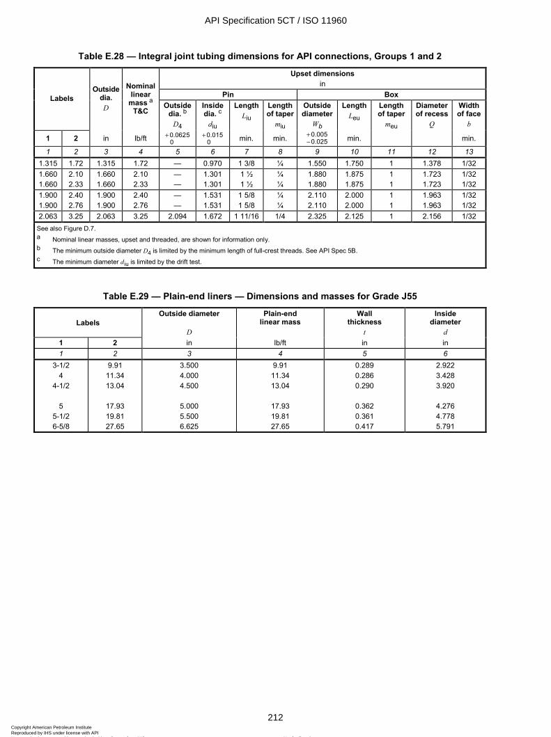
ISO 11960:2004(E)
212 © ISO 2004 – All rights reserved
Table E.28 — Integral joint tubing dimensions for API connections, Groups 1 and 2
Upset dimensions in
Pin Box Labels Outside
dia. D
Nominal linear
mass a T&C
Outside dia. b
D4
Inside dia. c
diu
Length Liu
Length of taper
miu
Outside diameter
Wb
Length Leu
Length of taper
meu
Diameter of recess
Q
Width of face
b
1 2 in lb/ft 0.06250
+ 0.0150
+ min. min. 0.0050.025
+-
min. min.
1 2 3 4 5 6 7 8 9 10 11 12 13 1.315 1.72 1.315 1.72 — 0.970 1 3/8 ¼ 1.550 1.750 1 1.378 1/32 1.660 1.660
2.10 2.33
1.660 1.660
2.10 2.33
— —
1.301 1.301
1 ½ 1 ½
¼ ¼
1.880 1.880
1.875 1.875
1 1
1.723 1.723
1/32 1/32
1.900 1.900
2.40 2.76
1.900 1.900
2.40 2.76
— —
1.531 1.531
1 5/8 1 5/8
¼ ¼
2.110 2.110
2.000 2.000
1 1
1.963 1.963
1/32 1/32
2.063 3.25 2.063 3.25 2.094 1.672 1 11/16 1/4 2.325 2.125 1 2.156 1/32 See also Figure D.7. a Nominal linear masses, upset and threaded, are shown for information only. b The minimum outside diameter D4 is limited by the minimum length of full-crest threads. See API Spec 5B. c The minimum diameter d iu is limited by the drift test.
Table E.29 — Plain-end liners — Dimensions and masses for Grade J55
Labels Outside diameter
D
Plain-end linear mass
Wall thickness
t
Inside diameter
d 1 2 in lb/ft in in 1 2 3 4 5 6
3-1/2 4
4-1/2
5 5-1/2 6-5/8
9.91 11.34 13.04
17.93 19.81 27.65
3.500 4.000 4.500
5.000 5.500 6.625
9.91 11.34 13.04
17.93 19.81 27.65
0.289 0.286 0.290
0.362 0.361 0.417
2.922 3.428 3.920
4.276 4.778 5.791
API Specification 5CT / ISO 11960
212Copyright American Petroleum Institute Reproduced by IHS under license with API
Not for ResaleNo reproduction or networking permitted without license from IHS
--`,,,```-`-`,,`,,`,`,,`---
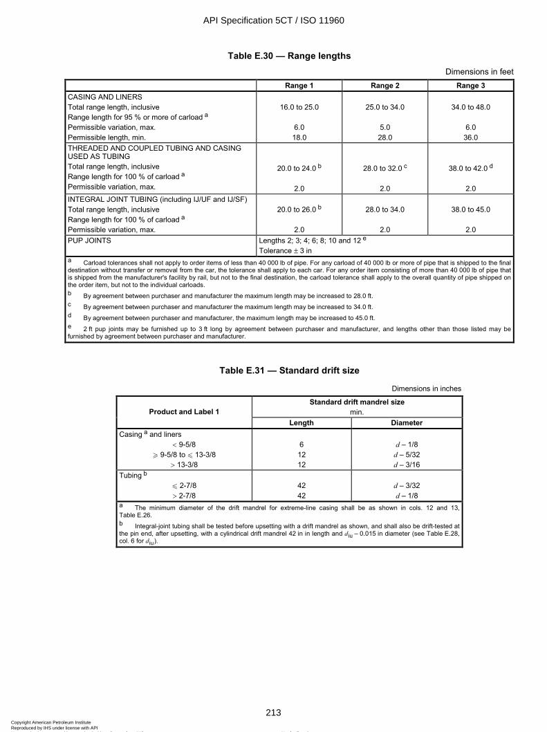
ISO 11960:2004(E)
© ISO 2004 – All rights reserved 213
Table E.30 — Range lengths
Dimensions in feet Range 1 Range 2 Range 3
CASING AND LINERS Total range length, inclusive Range length for 95 % or more of carload a Permissible variation, max. Permissible length, min.
16.0 to 25.0
6.0 18.0
25.0 to 34.0
5.0 28.0
34.0 to 48.0
6.0
36.0 THREADED AND COUPLED TUBING AND CASING USED AS TUBING Total range length, inclusive Range length for 100 % of carload a Permissible variation, max.
20.0 to 24.0 b
2.0
28.0 to 32.0 c
2.0
38.0 to 42.0 d
2.0 INTEGRAL JOINT TUBING (including IJ/UF and IJ/SF) Total range length, inclusive Range length for 100 % of carload a Permissible variation, max.
20.0 to 26.0 b
2.0
28.0 to 34.0
2.0
38.0 to 45.0
2.0
PUP JOINTS Lengths 2; 3; 4; 6; 8; 10 and 12 e Tolerance ± 3 in
a Carload tolerances shall not apply to order items of less than 40 000 lb of pipe. For any carload of 40 000 lb or more of pipe that is shipped to the final destination without transfer or removal from the car, the tolerance shall apply to each car. For any order item consisting of more than 40 000 lb of pipe that is shipped from the manufacturer's facility by rail, but not to the final destination, the carload tolerance shall apply to the overall quantity of pipe shipped on the order item, but not to the individual carloads. b By agreement between purchaser and manufacturer the maximum length may be increased to 28.0 ft. c By agreement between purchaser and manufacturer the maximum length may be increased to 34.0 ft. d By agreement between purchaser and manufacturer, the maximum length may be increased to 45.0 ft. e 2 ft pup joints may be furnished up to 3 ft long by agreement between purchaser and manufacturer, and lengths other than those listed may be furnished by agreement between purchaser and manufacturer.
Table E.31 — Standard drift size
Dimensions in inches
Standard drift mandrel size min. Product and Label 1
Length Diameter Casing a and liners
< 9-5/8 W 9-5/8 to u 13-3/8
> 13-3/8
6 12 12
d – 1/8
d – 5/32 d – 3/16
Tubing b u 2-7/8 > 2-7/8
42 42
d – 3/32 d – 1/8
a The minimum diameter of the drift mandrel for extreme-line casing shall be as shown in cols. 12 and 13, Table E.26. b Integral-joint tubing shall be tested before upsetting with a drift mandrel as shown, and shall also be drift-tested at the pin end, after upsetting, with a cylindrical drift mandrel 42 in in length and d iu – 0.015 in diameter (see Table E.28, col. 6 for d iu).
API Specification 5CT / ISO 11960
213Copyright American Petroleum Institute Reproduced by IHS under license with API
Not for ResaleNo reproduction or networking permitted without license from IHS
--`,,,```-`-`,,`,,`,`,,`---
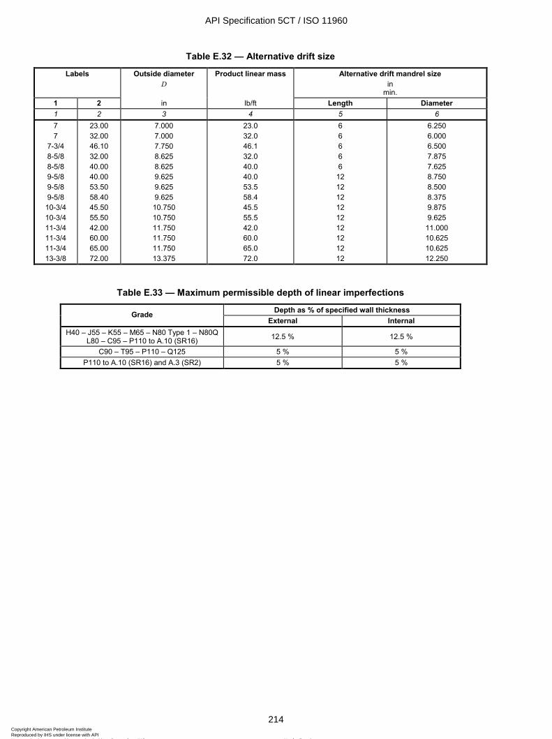
ISO 11960:2004(E)
214 © ISO 2004 – All rights reserved
Table E.32 — Alternative drift size
Labels Outside diameter D
Product linear mass Alternative drift mandrel size in
min. 1 2 in lb/ft Length Diameter 1 2 3 4 5 6 7 7
7-3/4 8-5/8 8-5/8 9-5/8 9-5/8 9-5/8
10-3/4 10-3/4 11-3/4 11-3/4 11-3/4 13-3/8
23.00 32.00 46.10 32.00 40.00 40.00 53.50 58.40 45.50 55.50 42.00 60.00 65.00 72.00
7.000 7.000 7.750 8.625 8.625 9.625 9.625 9.625 10.750 10.750 11.750 11.750 11.750 13.375
23.0 32.0 46.1 32.0 40.0 40.0 53.5 58.4 45.5 55.5 42.0 60.0 65.0 72.0
6 6 6 6 6
12 12 12 12 12 12 12 12 12
6.250 6.000 6.500 7.875 7.625 8.750 8.500 8.375 9.875 9.625
11.000 10.625 10.625 12.250
Table E.33 — Maximum permissible depth of linear imperfections
Depth as % of specified wall thickness Grade External Internal
H40 – J55 – K55 – M65 – N80 Type 1 – N80Q L80 – C95 – P110 to A.10 (SR16) 12.5 % 12.5 %
C90 – T95 – P110 – Q125 5 % 5 % P110 to A.10 (SR16) and A.3 (SR2) 5 % 5 %
API Specification 5CT / ISO 11960
214Copyright American Petroleum Institute Reproduced by IHS under license with API
Not for ResaleNo reproduction or networking permitted without license from IHS
--`,,,```-`-`,,`,,`,`,,`---
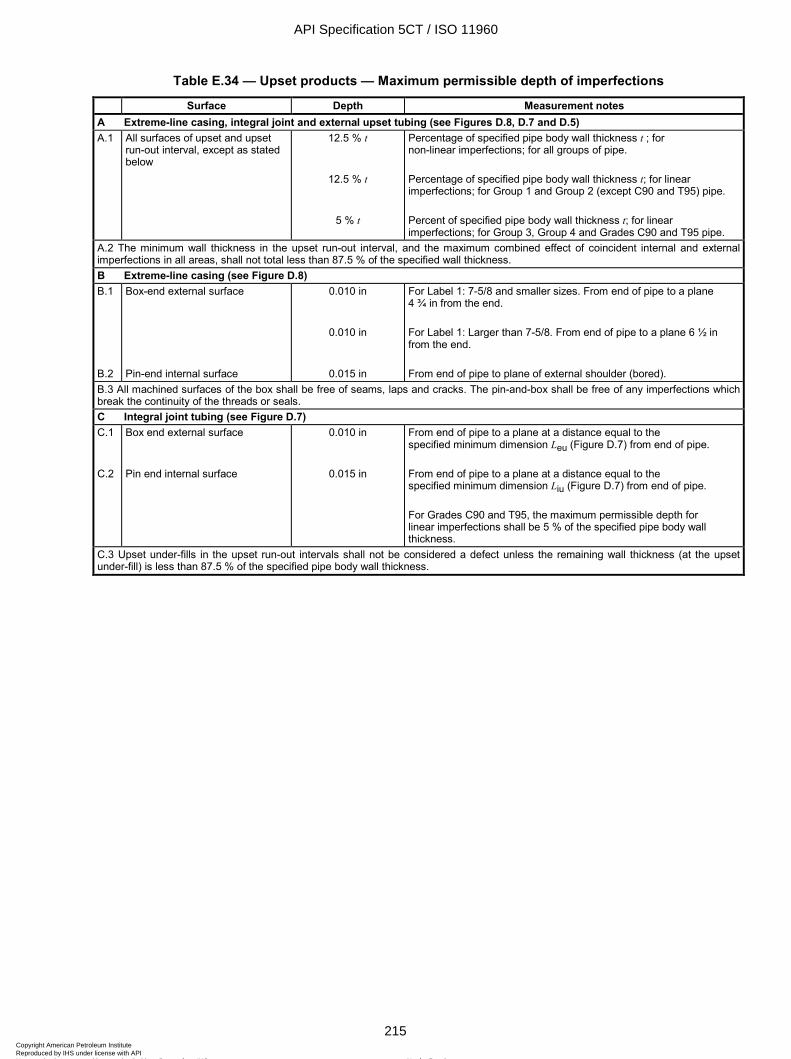
ISO 11960:2004(E)
© ISO 2004 – All rights reserved 215
Table E.34 — Upset products — Maximum permissible depth of imperfections
Surface Depth Measurement notes A Extreme-line casing, integral joint and external upset tubing (see Figures D.8, D.7 and D.5) A.1 All surfaces of upset and upset
run-out interval, except as stated below
12.5 % t
12.5 % t
5 % t
Percentage of specified pipe body wall thickness t ; for non-linear imperfections; for all groups of pipe. Percentage of specified pipe body wall thickness t; for linear imperfections; for Group 1 and Group 2 (except C90 and T95) pipe. Percent of specified pipe body wall thickness t; for linear imperfections; for Group 3, Group 4 and Grades C90 and T95 pipe.
A.2 The minimum wall thickness in the upset run-out interval, and the maximum combined effect of coincident internal and external imperfections in all areas, shall not total less than 87.5 % of the specified wall thickness. B Extreme-line casing (see Figure D.8) B.1 B.2
Box-end external surface Pin-end internal surface
0.010 in
0.010 in
0.015 in
For Label 1: 7-5/8 and smaller sizes. From end of pipe to a plane 4 ¾ in from the end. For Label 1: Larger than 7-5/8. From end of pipe to a plane 6 ½ in from the end. From end of pipe to plane of external shoulder (bored).
B.3 All machined surfaces of the box shall be free of seams, laps and cracks. The pin-and-box shall be free of any imperfections which break the continuity of the threads or seals. C Integral joint tubing (see Figure D.7) C.1 C.2
Box end external surface Pin end internal surface
0.010 in
0.015 in
From end of pipe to a plane at a distance equal to the specified minimum dimension Leu (Figure D.7) from end of pipe. From end of pipe to a plane at a distance equal to the specified minimum dimension Liu (Figure D.7) from end of pipe. For Grades C90 and T95, the maximum permissible depth for linear imperfections shall be 5 % of the specified pipe body wall thickness.
C.3 Upset under-fills in the upset run-out intervals shall not be considered a defect unless the remaining wall thickness (at the upset under-fill) is less than 87.5 % of the specified pipe body wall thickness.
API Specification 5CT / ISO 11960
215Copyright American Petroleum Institute Reproduced by IHS under license with API
Not for ResaleNo reproduction or networking permitted without license from IHS
--`,,,```-`-`,,`,,`,`,,`---
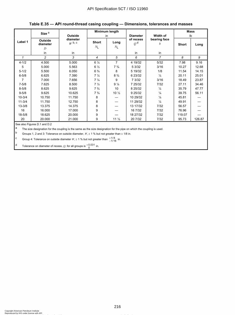
ISO 11960:2004(E)
216 © ISO 2004 – All rights reserved
Table E.35 — API round-thread casing coupling — Dimensions, tolerances and masses
Size a Minimum length in
Mass lb
Outside diameter
D
Outside diameter
W b, c Short NL
Long NL
Diameter of recess
Q d
Width of bearing face
b Short Long Label 1
in in in in 1 2 3 4 5 6 7 8 9
4-1/2 5
5-1/2 6-5/8
7 7-5/8 8-5/8 9-5/8 10-3/4 11-3/4 13-3/8
16 18-5/8
20
4.500 5.000 5.500 6.625 7.000 7.625 8.625 9.625
10.750 11.750 13.375 16.000 18.625 20.000
5.000 5.563 6.050 7.390 7.656 8.500 9.625
10.625 11.750 12.750 14.375 17.000 20.000 21.000
6 ¼ 6 ½ 6 ¾ 7 ¼ 7 ¼ 7 ½ 7 ¾ 7 ¾ 8 8 8 9 9 9
7 7 ¾ 8
8 ¾ 9
9 ¼ 10
10 ½ — — — — —
11 ½
4 19/32 5 3/32
5 19/32 6 23/32 7 3/32
7 25/32 8 25/32 9 25/32 10 29/32 11 29/32 13 17/32 16 7/32 18 27/32 20 7/32
5/32 3/16 1/8 ¼
3/16 7/32 ¼ ¼ ¼ ¼
7/32 7/32 7/32 7/32
7.98 10.27 11.54 20.11 18.49 27.11 35.79 39.75 45.81 49.91 56.57 76.96
119.07 95.73
9.16 12.68 14.15 25.01 23.87 34.46 47.77 56.11
— — — — —
126.87 See also Figures D.1 and D.2 a The size designation for the coupling is the same as the size designation for the pipe on which the coupling is used. b Groups 1, 2 and 3: Tolerance on outside diameter, W, ± 1 % but not greater than ± 1/8 in. c Group 4: Tolerance on outside diameter W, ± 1 % but not greater than 1/ 8
1/16+- in.
d Tolerance on diameter of recess, Q, for all groups is 0.0310
+ in.
API Specification 5CT / ISO 11960
216Copyright American Petroleum Institute Reproduced by IHS under license with API
Not for ResaleNo reproduction or networking permitted without license from IHS
--`,,,```-`-`,,`,,`,`,,`---
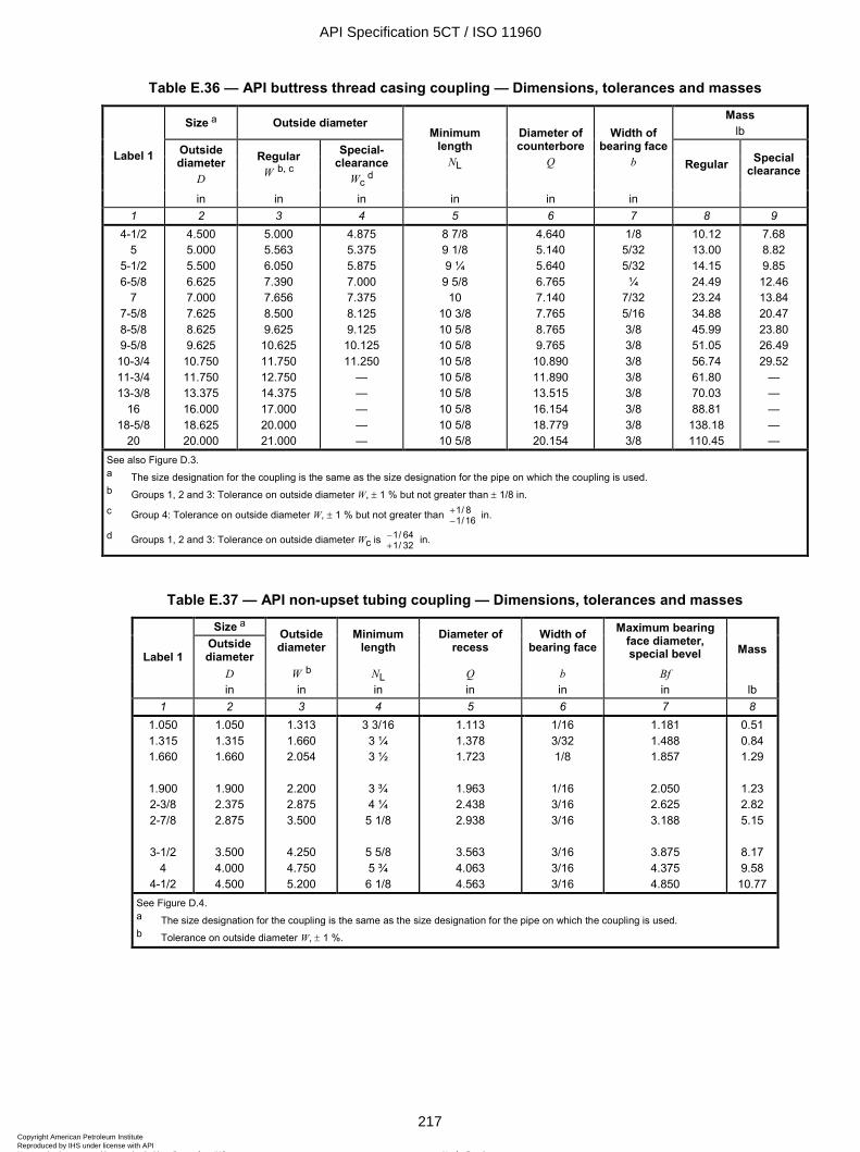
ISO 11960:2004(E)
© ISO 2004 – All rights reserved 217
Table E.36 — API buttress thread casing coupling — Dimensions, tolerances and masses
Size a Outside diameter Mass lb
Outside diameter
D
Regular W b, c
Special-clearance
Wc d
Minimum length
NL
Diameter ofcounterbore
Q
Width of bearing face
b Regular Special clearance
Label 1
in in in in in in 1 2 3 4 5 6 7 8 9
4-1/2 5
5-1/2 6-5/8
7 7-5/8 8-5/8 9-5/8 10-3/4 11-3/4 13-3/8
16 18-5/8
20
4.500 5.000 5.500 6.625 7.000 7.625 8.625 9.625
10.750 11.750 13.375 16.000 18.625 20.000
5.000 5.563 6.050 7.390 7.656 8.500 9.625 10.625 11.750 12.750 14.375 17.000 20.000 21.000
4.875 5.375 5.875 7.000 7.375 8.125 9.125 10.125 11.250
— — — — —
8 7/8 9 1/8 9 ¼
9 5/8 10
10 3/8 10 5/8 10 5/8 10 5/8 10 5/8 10 5/8 10 5/8 10 5/8 10 5/8
4.640 5.140 5.640 6.765 7.140 7.765 8.765 9.765 10.890 11.890 13.515 16.154 18.779 20.154
1/8 5/32 5/32 ¼
7/32 5/16 3/8 3/8 3/8 3/8 3/8 3/8 3/8 3/8
10.12 13.00 14.15 24.49 23.24 34.88 45.99 51.05 56.74 61.80 70.03 88.81
138.18 110.45
7.68 8.82 9.85 12.46 13.84 20.47 23.80 26.49 29.52
— — — — —
See also Figure D.3. a The size designation for the coupling is the same as the size designation for the pipe on which the coupling is used. b Groups 1, 2 and 3: Tolerance on outside diameter W, ± 1 % but not greater than ± 1/8 in. c Group 4: Tolerance on outside diameter W, ± 1 % but not greater than 1/ 8
1/16+- in.
d Groups 1, 2 and 3: Tolerance on outside diameter Wc is 1/ 641/ 32
-+ in.
Table E.37 — API non-upset tubing coupling — Dimensions, tolerances and masses
Size a Outside diameter
Outside diameter
Minimum length
Diameter of recess
Width of bearing face
Maximum bearing face diameter, special bevel
D W b NL Q b Bf
Mass Label 1
in in in in in in lb 1 2 3 4 5 6 7 8
1.050 1.315 1.660
1.900 2-3/8 2-7/8
3-1/2
4 4-1/2
1.050 1.315 1.660
1.900 2.375 2.875
3.500 4.000 4.500
1.313 1.660 2.054
2.200 2.875 3.500
4.250 4.750 5.200
3 3/16 3 ¼ 3 ½
3 ¾ 4 ¼ 5 1/8
5 5/8 5 ¾ 6 1/8
1.113 1.378 1.723
1.963 2.438 2.938
3.563 4.063 4.563
1/16 3/32 1/8
1/16 3/16 3/16
3/16 3/16 3/16
1.181 1.488 1.857
2.050 2.625 3.188
3.875 4.375 4.850
0.51 0.84 1.29
1.23 2.82 5.15
8.17 9.58
10.77 See Figure D.4. a The size designation for the coupling is the same as the size designation for the pipe on which the coupling is used. b Tolerance on outside diameter W, ± 1 %.
API Specification 5CT / ISO 11960
217Copyright American Petroleum Institute Reproduced by IHS under license with API
Not for ResaleNo reproduction or networking permitted without license from IHS
--`,,,```-`-`,,`,,`,`,,`---
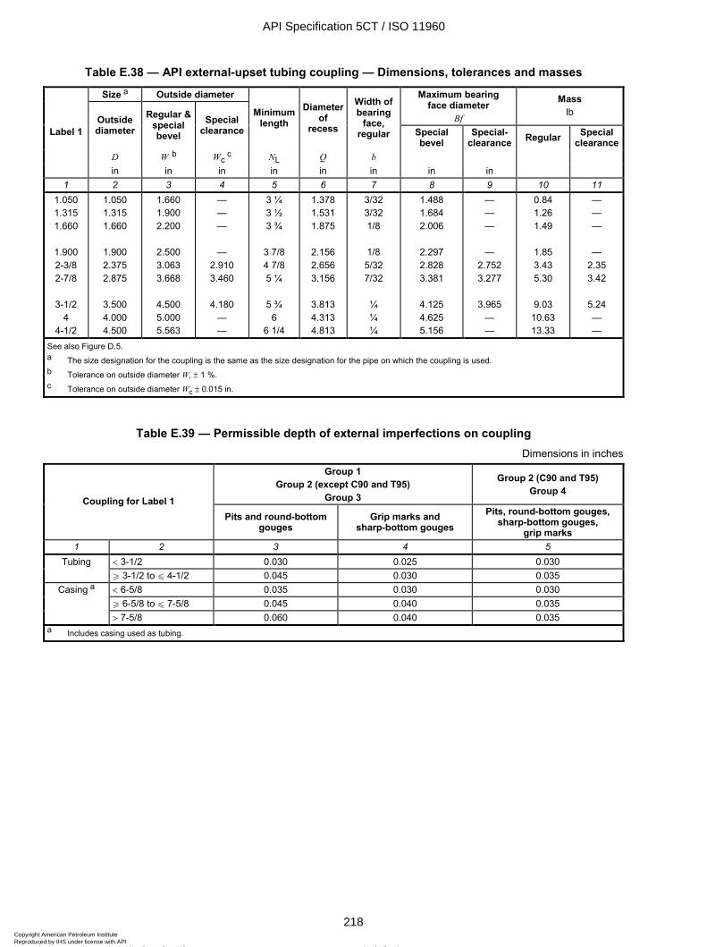
ISO 11960:2004(E)
218 © ISO 2004 – All rights reserved
Table E.38 — API external-upset tubing coupling — Dimensions, tolerances and masses
Size a Outside diameter Maximum bearing face diameter
Bf
Mass lb
Outside diameter
Regular & special bevel
Special clearance
Minimum length
Diameter of
recess
Width of bearing
face, regular Special
bevel Special-
clearance Regular Special clearance
D W b Wc c NL Q b
Label 1
in in in in in in in in 1 2 3 4 5 6 7 8 9 10 11
1.050 1.315 1.660
1.900 2-3/8 2-7/8
3-1/2
4 4-1/2
1.050 1.315 1.660
1.900 2.375 2.875
3.500 4.000 4.500
1.660 1.900 2.200
2.500 3.063 3.668
4.500 5.000 5.563
— — —
— 2.910 3.460
4.180
— —
3 ¼ 3 ½ 3 ¾
3 7/8 4 7/8 5 ¼
5 ¾
6 6 1/4
1.378 1.531 1.875
2.156 2.656 3.156
3.813 4.313 4.813
3/32 3/32 1/8
1/8 5/32 7/32
¼ ¼ ¼
1.488 1.684 2.006
2.297 2.828 3.381
4.125 4.625 5.156
— — —
— 2.752 3.277
3.965
— —
0.84 1.26 1.49
1.85 3.43 5.30
9.03
10.63 13.33
— — —
— 2.35 3.42
5.24 — —
See also Figure D.5. a The size designation for the coupling is the same as the size designation for the pipe on which the coupling is used. b Tolerance on outside diameter W, ± 1 %. c Tolerance on outside diameter Wc ± 0.015 in.
Table E.39 — Permissible depth of external imperfections on coupling Dimensions in inches
Group 1 Group 2 (except C90 and T95)
Group 3
Group 2 (C90 and T95) Group 4
Coupling for Label 1 Pits and round-bottom
gouges Grip marks and
sharp-bottom gouges Pits, round-bottom gouges,
sharp-bottom gouges, grip marks
1 2 3 4 5 < 3-1/2 0.030 0.025 0.030 Tubing W 3-1/2 to u 4-1/2 0.045 0.030 0.035 < 6-5/8 0.035 0.030 0.030 W 6-5/8 to u 7-5/8 0.045 0.040 0.035
Casing a
> 7-5/8 0.060 0.040 0.035 a Includes casing used as tubing.
API Specification 5CT / ISO 11960
218Copyright American Petroleum Institute Reproduced by IHS under license with API
Not for ResaleNo reproduction or networking permitted without license from IHS
--`,,,```-`-`,,`,,`,`,,`---
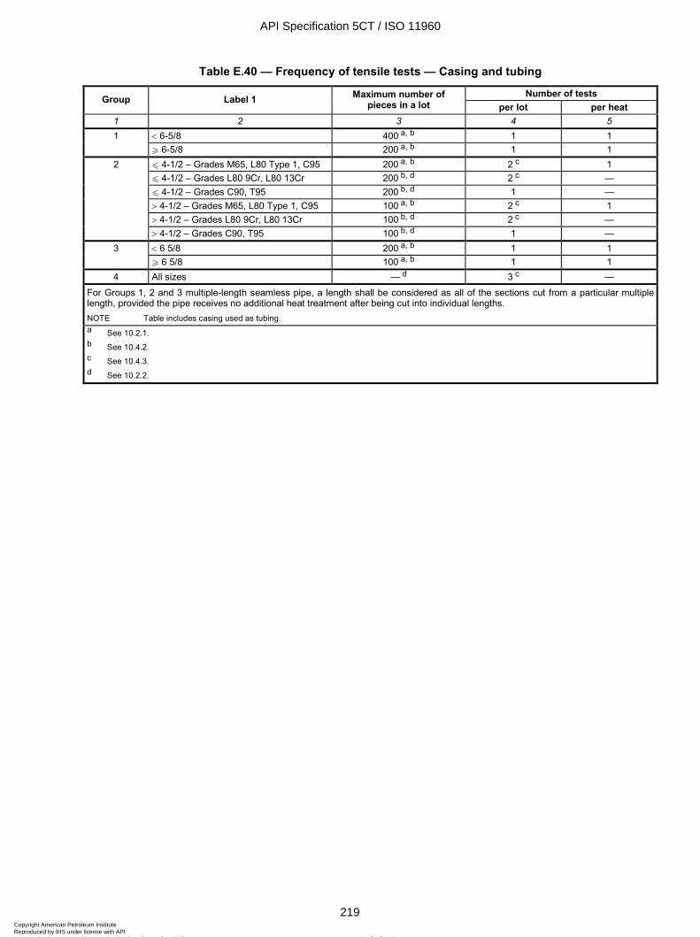
ISO 11960:2004(E)
© ISO 2004 – All rights reserved 219
Table E.40 — Frequency of tensile tests — Casing and tubing
Number of tests Group Label 1 Maximum number of pieces in a lot per lot per heat
1 2 3 4 5 < 6-5/8 400 a, b 1 1 1 W 6-5/8 200 a, b 1 1 u 4-1/2 – Grades M65, L80 Type 1, C95 200 a, b 2 c 1 u 4-1/2 – Grades L80 9Cr, L80 13Cr 200 b, d 2 c — u 4-1/2 – Grades C90, T95 200 b, d 1 — > 4-1/2 – Grades M65, L80 Type 1, C95 100 a, b 2 c 1 > 4-1/2 – Grades L80 9Cr, L80 13Cr 100 b, d 2 c —
2
> 4-1/2 – Grades C90, T95 100 b, d 1 — < 6 5/8 200 a, b 1 1 3 W 6 5/8 100 a, b 1 1
4 All sizes — d 3 c —
For Groups 1, 2 and 3 multiple-length seamless pipe, a length shall be considered as all of the sections cut from a particular multiple length, provided the pipe receives no additional heat treatment after being cut into individual lengths. NOTE Table includes casing used as tubing. a See 10.2.1. b See 10.4.2. c See 10.4.3. d See 10.2.2.
API Specification 5CT / ISO 11960
219Copyright American Petroleum Institute Reproduced by IHS under license with API
Not for ResaleNo reproduction or networking permitted without license from IHS
--`,,,```-`-`,,`,,`,`,,`---
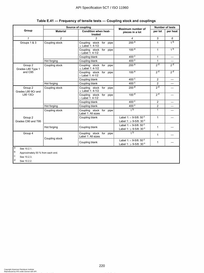
ISO 11960:2004(E)
220 © ISO 2004 – All rights reserved
Table E.41 — Frequency of tensile tests — Coupling stock and couplings
Source of coupling Number of tests Group Material Condition when heat-
treated
Maximum number of pieces in a lot per lot per heat
1 2 3 4 5 6 Coupling stock for pipe u Label 1: 4-1/2
200 a 1 1 b
Coupling stock for pipe > Label 1: 4-1/2
100 a 1 1 b
Coupling stock
Coupling blank 400 c 1 —
Groups 1 & 3
Hot forging Coupling blank 400 c 1 — Coupling stock for pipe u Label 1: 4-1/2
200 a 2 d 2 d
Coupling stock for pipe > Label 1: 4-1/2
100 a 2 d 2 d
Coupling stock
Coupling blank 400 c 2 —
Group 2 Grades L80 Type 1
and C95
Hot forging Coupling blank 400 c 2 — Coupling stock for pipe u Label 1: 4-1/2
200 d 2 d —
Coupling stock for pipe > Label 1: 4-1/2
100 d 2 d —
Coupling stock
Coupling blank 400 c 2 —
Group 2 Grades L80 9Cr and
L80 13Cr
Hot forging Coupling blank 400 c 2 — Coupling stock for pipe Label 1: All sizes
1 b 1 — Coupling stock
Coupling blank Label 1: < 9-5/8: 50 c
Label 1: W 9-5/8: 30 c 1 — Group 2
Grades C90 and T95
Hot forging Coupling blank Label 1: < 9-5/8: 50 c
Label 1: W 9-5/8: 30 c 1 —
Coupling stock for pipe Label 1: All sizes
1 b 1 — Group 4
Coupling stock Coupling blank
Label 1: < 9-5/8: 50 c
Label 1: W 9-5/8: 30 c 1 —
a See 10.2.1. b Approximately 50 % from each end. c See 10.2.3. d See 10.2.2.
API Specification 5CT / ISO 11960
220Copyright American Petroleum Institute Reproduced by IHS under license with API
Not for ResaleNo reproduction or networking permitted without license from IHS
--`,,,```-`-`,,`,,`,`,,`---
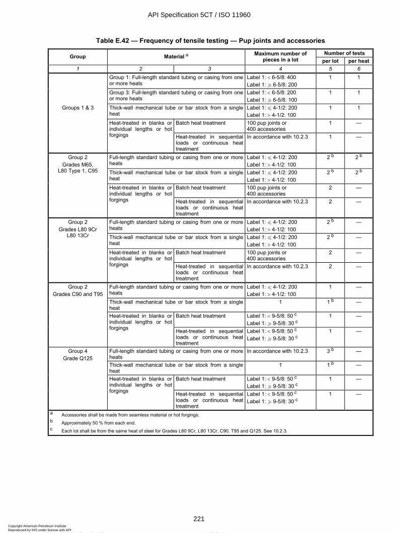
ISO 11960:2004(E)
© ISO 2004 – All rights reserved 221
Table E.42 — Frequency of tensile testing — Pup joints and accessories
Number of tests Group Material a Maximum number of pieces in a lot per lot per heat
1 2 3 4 5 6 Group 1: Full-length standard tubing or casing from one
or more heats Label 1: < 6-5/8: 400 Label 1: W 6-5/8: 200
1 1
Group 3: Full-length standard tubing or casing from one or more heats
Label 1: < 6-5/8: 200 Label 1: W 6-5/8: 100
1 1
Groups 1 & 3 Thick-wall mechanical tube or bar stock from a single heat
Label 1: u 4-1/2: 200 Label 1: > 4-1/2: 100
1 1
Batch heat treatment 100 pup joints or 400 accessories
1 —
Heat-treated in blanks or individual lengths or hot forgings Heat-treated in sequential
loads or continuous heat treatment
In accordance with 10.2.3 1 —
Full-length standard tubing or casing from one or more heats
Label 1: u 4-1/2: 200 Label 1: > 4-1/2: 100
2 b 2 b
Thick-wall mechanical tube or bar stock from a single heat
Label 1: u 4-1/2: 200 Label 1: > 4-1/2: 100
2 b 2 b
Batch heat treatment 100 pup joints or 400 accessories
2 —
Group 2 Grades M65,
L80 Type 1, C95
Heat-treated in blanks or individual lengths or hot forgings Heat-treated in sequential
loads or continuous heat treatment
In accordance with 10.2.3 2 —
Full-length standard tubing or casing from one or more heats
Label 1: u 4-1/2: 200 Label 1: > 4-1/2: 100
2 b —
Thick-wall mechanical tube or bar stock from a single heat
Label 1: u 4-1/2: 200 Label 1: > 4-1/2: 100
2 b —
Batch heat treatment 100 pup joints or 400 accessories
2 —
Group 2 Grades L80 9Cr
L80 13Cr
Heat-treated in blanks or individual lengths or hot forgings Heat-treated in sequential
loads or continuous heat treatment
In accordance with 10.2.3 2 —
Full-length standard tubing or casing from one or more heats
Label 1: u 4-1/2: 200 Label 1: > 4-1/2: 100
1 —
Thick-wall mechanical tube or bar stock from a single heat
1 1 b —
Batch heat treatment Label 1: < 9-5/8: 50 c Label 1: W 9-5/8: 30 c
1 —
Group 2 Grades C90 and T95
Heat-treated in blanks or individual lengths or hot forgings Heat-treated in sequential
loads or continuous heat treatment
Label 1: < 9-5/8: 50 c Label 1: W 9-5/8: 30 c
1 —
Full-length standard tubing or casing from one or more heats
In accordance with 10.2.3 3 b —
Thick-wall mechanical tube or bar stock from a single heat
1 1 b —
Batch heat treatment Label 1: < 9-5/8: 50 c Label 1: W 9-5/8: 30 c
1 —
Group 4 Grade Q125
Heat-treated in blanks or individual lengths or hot forgings Heat-treated in sequential
loads or continuous heat treatment
Label 1: < 9-5/8: 50 c Label 1: W 9-5/8: 30 c
1 —
a Accessories shall be made from seamless material or hot forgings. b Approximately 50 % from each end. c Each lot shall be from the same heat of steel for Grades L80 9Cr, L80 13Cr, C90, T95 and Q125. See 10.2.3.
API Specification 5CT / ISO 11960
221Copyright American Petroleum Institute Reproduced by IHS under license with API
Not for ResaleNo reproduction or networking permitted without license from IHS
--`,,,```-`-`,,`,,`,`,,`---
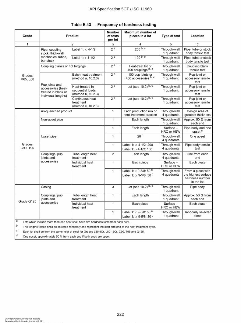
ISO 11960:2004(E)
222 © ISO 2004 – All rights reserved
Table E.43 — Frequency of hardness testing
Grade Product Number of tests per lot
Maximum number of pieces in a lot Type of test Location
1 2 3 4 5 6 Label 1: u 4-1/2 2 a 200 b, c Through-wall,
1 quadrant Pipe, tube or stock body tensile test
Pipe, coupling stock, thick-wall mechanical tubes, bar stock
Label 1: > 4-1/2 2 a 100 b, c Through-wall, 1 quadrant
Pipe, tube or stock body tensile test
Coupling blanks or hot forgings 2 a Heat-treat lot or 400 couplings b, c
Through-wall, 1 quadrant
Coupling blank tensile test
Batch heat treatment (method a, 10.2.3)
2 a 100 pup joints or 400 accessories b, c
Through-wall, 1 quadrant
Pup-joint or accessory tensile
test Heat-treated in sequential loads (method b, 10.2.3)
2 a Lot (see 10.2) b, c Through-wall, 1 quadrant
Pup-joint or accessory tensile
test
Grades M65, L80
Pup joints and accessories (heat-treated in blank or individual lengths)
Continuous heat treatment (method c, 10.2.3)
2 a Lot (see 10.2) b, c Through-wall, 1 quadrant
Pup-joint or accessory tensile
test As-quenched product 1 Each production run or
heat-treatment practice Through-wall, 4 quadrants
Design area of greatest thickness
Non-upset pipe 1 Each length Through-wall, 1 quadrant
Approx. 50 % from each end
1 Each length Surface – HRC or HBW
Pipe body and one upset d
Upset pipe 1 20 c Through-wall, 4 quadrants
One upset
1 Label 1: u 4-1/2: 200 Label 1: > 4-1/2: 100
Through-wall, 4 quadrants
Pipe body tensile test
Tube length heat treatment
2 Each length Through-wall, 4 quadrants
One from each end
1 Each piece Surface – HRC or HBW
Each piece
Grades C90, T95
Couplings, pup joints and accessories Individual heat
treatment 1 Label 1: < 9-5/8: 50 c
Label 1: W 9-5/8: 30 c Through-wall, 4 quadrants
From a piece with the highest surface hardness number
in the lot Casing 3 Lot (see 10.2) b, c Through-wall,
1 quadrant Pipe body
Tube length heat treatment
1 Each length Through-wall, 1 quadrant
Approx. 50 % from each end
1 Each piece Surface – HRC or HBW
Each piece Grade Q125
Couplings, pup joints and accessories Individual heat
treatment 1 Label 1: < 9-5/8: 50 c
Label 1: W 9-5/8: 30 c Through-wall,
1 quadrant Randomly selected
piece a Lots which include more than one heat shall have two hardness tests from each heat. b The lengths tested shall be selected randomly and represent the start and end of the heat treatment cycle. c Each lot shall be from the same heat of steel for Grades L80 9Cr, L80 13Cr, C90, T95 and Q125. d One upset, approximately 50 % from each end if both ends are upset.
API Specification 5CT / ISO 11960
222Copyright American Petroleum Institute Reproduced by IHS under license with API
Not for ResaleNo reproduction or networking permitted without license from IHS
--`,,,```-`-`,,`,,`,`,,`---

ISO 11960:2004(E)
© ISO 2004 – All rights reserved 223
Table E.44 — Frequency of flattening tests
Casing and tubing Group Type of heat treatment Number of tests
1 2 3 4 Non-full body As described in footnote a
u Label 1: 4-1/2 Same as non-full body heat-treated or 1 per lot of 100 lengths or less 1, 2 and 3
Full body > Label 1: 4-1/2 b Same as non-full body heat-treated or 1 per lot of
20 lengths or less 4 All 1 on each end of each length of pipe [see A.5 (SR11)]
Pup joints Number of tests Group Source of pup joint Maximum number of
pieces in a lot per lot per heat 1 2 3 4 5 6
Batch heat-treated 100 pup joints Treated separately
Continuously heat-treated — u Label 1: 4-1/2 200 lengths
1, 2 and 3 Manufactured from EW pipe
> Label 1: 4-1/2 b 100 lengths
1 1
4 All 1 on each end of each length of pipe
a The leading end of the first pipe of each coil shall have two test specimens flattened: one in the 90° position and one in the 0° position. Two test specimens shall be flattened from an intermediate pipe of each coil: one in the 90° position and one in the 0° position. The trailing end of the last pipe of each coil shall have two test specimens flattened: one in the 90° position and one in the 0° position. When a weld stop condition occurs during production of a multiple length, flattening tests with the weld at the 90° position and 0° position shall be made from the crop end resulting from each side of the weld stop, and may be substituted for the intermediate flattening tests. 90° position: the weld is positioned at 3 o’clock or at 9 o’clock. 0° position: the weld is positioned at 6 o’clock or at 12 o’clock. b Includes casing used as tubing.
API Specification 5CT / ISO 11960
223Copyright American Petroleum Institute Reproduced by IHS under license with API
Not for ResaleNo reproduction or networking permitted without license from IHS
--`,,,```-`-`,,`,,`,`,,`---

ISO 11960:2004(E)
224 © ISO 2004 – All rights reserved
Table E.45 — Hydrostatic test pressure for Grade H40 casing
Test pressure psi
Round thread a Label 1 Label 2
Plain end STC LC
1 2 3 4 5 4-1/2 9.50 2 900 2 900 — 5-1/2 14.00 2 800 2 800 — 6-5/8 20.00 2 800 2 800 —
7 17.00 2 100 2 100 — 7 20.00 2 500 2 500 —
7-5/8 24.00 2 500 2 500 — 8-5/8 28.00 2 300 2 300 — 8-5/8 32.00 2 600 2 600 — 9-5/8 32.30 2 100 2 100 — 9-5/8 36.00 2 300 2 300 — 10-3/4 32.75 1 200
(1 700) 1 200
(1 700) — —
10-3/4 40.50 1 600 (2 100)
1 600 (2 100)
— —
11-3/4 42.00 1 400 (1 800)
1 400 (1 800)
— —
13-3/8 48.00 1 200 (1 600)
1 200 (1 600)
— —
16 65.00 1 100 (1 500)
1 100 (1 500)
— —
18-5/8 87.50 1 100 (1 500)
1 100 (1 500)
— —
20 94.00 1 100 (1 400)
1 100 (1 400)
1 100 (1 400)
NOTE Alternative test pressures are given in parentheses.
a The test pressures shown are for threaded and coupled pipe furnished with H40, J55 or K55 couplings.
API Specification 5CT / ISO 11960
224Copyright American Petroleum Institute Reproduced by IHS under license with API
Not for ResaleNo reproduction or networking permitted without license from IHS
--`,,,```-`-`,,`,,`,`,,`---
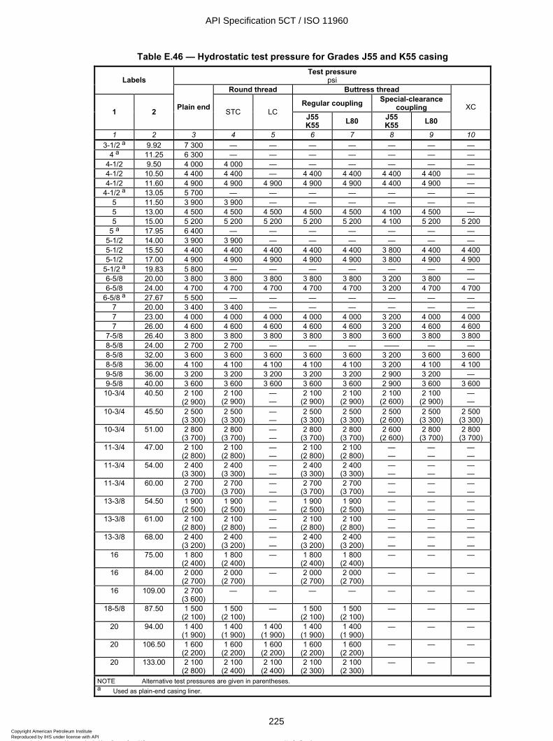
ISO 11960:2004(E)
© ISO 2004 – All rights reserved 225
Table E.46 — Hydrostatic test pressure for Grades J55 and K55 casing Test pressure
psi Labels Round thread Buttress thread
Regular coupling Special-clearance coupling 1 2 Plain end STC LC J55
K55 L80 J55 K55 L80
XC
1 2 3 4 5 6 7 8 9 10 3-1/2 a 9.92 7 300 — — — — — — —
4 a 11.25 6 300 — — — — — — — 4-1/2 9.50 4 000 4 000 — — — — — — 4-1/2 10.50 4 400 4 400 — 4 400 4 400 4 400 4 400 — 4-1/2 11.60 4 900 4 900 4 900 4 900 4 900 4 400 4 900 —
4-1/2 a 13.05 5 700 — — — — — — — 5 11.50 3 900 3 900 — — — — — — 5 13.00 4 500 4 500 4 500 4 500 4 500 4 100 4 500 — 5 15.00 5 200 5 200 5 200 5 200 5 200 4 100 5 200 5 200
5 a 17.95 6 400 — — — — — — — 5-1/2 14.00 3 900 3 900 — — — — — — 5-1/2 15.50 4 400 4 400 4 400 4 400 4 400 3 800 4 400 4 400 5-1/2 17.00 4 900 4 900 4 900 4 900 4 900 3 800 4 900 4 900
5-1/2 a 19.83 5 800 — — — — — — — 6-5/8 20.00 3 800 3 800 3 800 3 800 3 800 3 200 3 800 — 6-5/8 24.00 4 700 4 700 4 700 4 700 4 700 3 200 4 700 4 700
6-5/8 a 27.67 5 500 — — — — — — — 7 20.00 3 400 3 400 — — — — — — 7 23.00 4 000 4 000 4 000 4 000 4 000 3 200 4 000 4 000 7 26.00 4 600 4 600 4 600 4 600 4 600 3 200 4 600 4 600
7-5/8 26.40 3 800 3 800 3 800 3 800 3 800 3 600 3 800 3 800 8-5/8 24.00 2 700 2 700 — — — —— — — 8-5/8 32.00 3 600 3 600 3 600 3 600 3 600 3 200 3 600 3 600 8-5/8 36.00 4 100 4 100 4 100 4 100 4 100 3 200 4 100 4 100 9-5/8 36.00 3 200 3 200 3 200 3 200 3 200 2 900 3 200 — 9-5/8 40.00 3 600 3 600 3 600 3 600 3 600 2 900 3 600 3 600 10-3/4 40.50 2 100
(2 900) 2 100
(2 900) — —
2 100 (2 900)
2 100 (2 900)
2 100 (2 600)
2 100 (2 900)
— —
10-3/4 45.50 2 500 (3 300)
2 500 (3 300)
— —
2 500 (3 300)
2 500 (3 300)
2 500 (2 600)
2 500 (3 300)
2 500 (3 300)
10-3/4 51.00 2 800 (3 700)
2 800 (3 700)
— —
2 800 (3 700)
2 800 (3 700)
2 600 (2 600)
2 800 (3 700)
2 800 (3 700)
11-3/4 47.00 2 100 (2 800)
2 100 (2 800)
— —
2 100 (2 800)
2 100 (2 800)
— —
— —
— —
11-3/4 54.00 2 400 (3 300)
2 400 (3 300)
— —
2 400 (3 300)
2 400 (3 300)
— —
— —
— —
11-3/4 60.00 2 700 (3 700)
2 700 (3 700)
— —
2 700 (3 700)
2 700 (3 700)
— —
— —
— —
13-3/8 54.50 1 900 (2 500)
1 900 (2 500)
— —
1 900 (2 500)
1 900 (2 500)
— —
— —
— —
13-3/8 61.00 2 100 (2 800)
2 100 (2 800)
— —
2 100 (2 800)
2 100 (2 800)
— —
— —
— —
13-3/8 68.00 2 400 (3 200)
2 400 (3 200)
— —
2 400 (3 200)
2 400 (3 200)
— —
— —
— —
16 75.00 1 800 (2 400)
1 800 (2 400)
— 1 800 (2 400)
1 800 (2 400)
— — —
16 84.00 2 000 (2 700)
2 000 (2 700)
— 2 000 (2 700)
2 000 (2 700)
— — —
16 109.00 2 700 (3 600)
— — — — — — —
18-5/8 87.50 1 500 (2 100)
1 500 (2 100)
— 1 500 (2 100)
1 500 (2 100)
— — —
20 94.00 1 400 (1 900)
1 400 (1 900)
1 400 (1 900)
1 400 (1 900)
1 400 (1 900)
— — —
20 106.50 1 600 (2 200)
1 600 (2 200)
1 600 (2 200)
1 600 (2 200)
1 600 (2 200)
— — —
20 133.00 2 100 (2 800)
2 100 (2 400)
2 100 (2 400)
2 100 (2 300)
2 100 (2 300)
— — —
NOTE Alternative test pressures are given in parentheses. a Used as plain-end casing liner.
API Specification 5CT / ISO 11960
225Copyright American Petroleum Institute Reproduced by IHS under license with API
Not for ResaleNo reproduction or networking permitted without license from IHS
--`,,,```-`-`,,`,,`,`,,`---
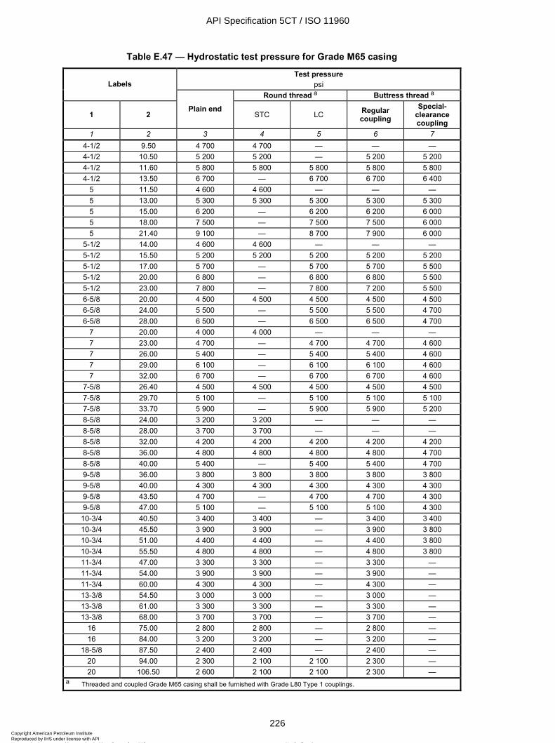
ISO 11960:2004(E)
226 © ISO 2004 – All rights reserved
Table E.47 — Hydrostatic test pressure for Grade M65 casing
Test pressure psi Labels
Round thread a Buttress thread a
1 2 Plain end
STC LC Regular coupling
Special-clearance coupling
1 2 3 4 5 6 7 4-1/2 9.50 4 700 4 700 — — — 4-1/2 10.50 5 200 5 200 — 5 200 5 200 4-1/2 11.60 5 800 5 800 5 800 5 800 5 800 4-1/2 13.50 6 700 — 6 700 6 700 6 400
5 11.50 4 600 4 600 — — — 5 13.00 5 300 5 300 5 300 5 300 5 300 5 15.00 6 200 — 6 200 6 200 6 000 5 18.00 7 500 — 7 500 7 500 6 000 5 21.40 9 100 — 8 700 7 900 6 000
5-1/2 14.00 4 600 4 600 — — — 5-1/2 15.50 5 200 5 200 5 200 5 200 5 200 5-1/2 17.00 5 700 — 5 700 5 700 5 500 5-1/2 20.00 6 800 — 6 800 6 800 5 500 5-1/2 23.00 7 800 — 7 800 7 200 5 500 6-5/8 20.00 4 500 4 500 4 500 4 500 4 500 6-5/8 24.00 5 500 — 5 500 5 500 4 700 6-5/8 28.00 6 500 — 6 500 6 500 4 700
7 20.00 4 000 4 000 — — — 7 23.00 4 700 — 4 700 4 700 4 600 7 26.00 5 400 — 5 400 5 400 4 600 7 29.00 6 100 — 6 100 6 100 4 600 7 32.00 6 700 — 6 700 6 700 4 600
7-5/8 26.40 4 500 4 500 4 500 4 500 4 500 7-5/8 29.70 5 100 — 5 100 5 100 5 100 7-5/8 33.70 5 900 — 5 900 5 900 5 200 8-5/8 24.00 3 200 3 200 — — — 8-5/8 28.00 3 700 3 700 — — — 8-5/8 32.00 4 200 4 200 4 200 4 200 4 200 8-5/8 36.00 4 800 4 800 4 800 4 800 4 700 8-5/8 40.00 5 400 — 5 400 5 400 4 700 9-5/8 36.00 3 800 3 800 3 800 3 800 3 800 9-5/8 40.00 4 300 4 300 4 300 4 300 4 300 9-5/8 43.50 4 700 — 4 700 4 700 4 300 9-5/8 47.00 5 100 — 5 100 5 100 4 300
10-3/4 40.50 3 400 3 400 — 3 400 3 400 10-3/4 45.50 3 900 3 900 — 3 900 3 800 10-3/4 51.00 4 400 4 400 — 4 400 3 800 10-3/4 55.50 4 800 4 800 — 4 800 3 800 11-3/4 47.00 3 300 3 300 — 3 300 — 11-3/4 54.00 3 900 3 900 — 3 900 — 11-3/4 60.00 4 300 4 300 — 4 300 — 13-3/8 54.50 3 000 3 000 — 3 000 — 13-3/8 61.00 3 300 3 300 — 3 300 — 13-3/8 68.00 3 700 3 700 — 3 700 —
16 75.00 2 800 2 800 — 2 800 — 16 84.00 3 200 3 200 — 3 200 —
18-5/8 87.50 2 400 2 400 — 2 400 — 20 94.00 2 300 2 100 2 100 2 300 — 20 106.50 2 600 2 100 2 100 2 300 —
a Threaded and coupled Grade M65 casing shall be furnished with Grade L80 Type 1 couplings.
API Specification 5CT / ISO 11960
226Copyright American Petroleum Institute Reproduced by IHS under license with API
Not for ResaleNo reproduction or networking permitted without license from IHS
--`,,,```-`-`,,`,,`,`,,`---

ISO 11960:2004(E)
© ISO 2004 – All rights reserved 227
Table E.48 — Hydrostatic test pressure for Grade L80 casing
Test pressure psi Labels
Round thread Buttress thread
1 2 Plain end
STC LC Regular coupling
Special-clearance coupling
XC
1 2 3 4 5 6 7 8 4-1/2 11.60 7 100 — 7 100 7 100 6 400 — 4-1/2 13.50 8 200 — 8 200 7 800 6 400 —
5 15.00 7 600 — 7 600 7 600 6 000 7 600 5 18.00 9 300 — 8 700 7 900 6 000 9 300 5 21.40 10 000 — 8 700 7 900 6 000 — 5 23.20 10 000 — 8 700 7 900 6 000 — 5 24.10 10 000 — 8 700 7 900 6 000 —
5-1/2 17.00 7 100 — 7 100 7 100 5 500 7 100 5-1/2 20.00 8 400 — 7 900 7 200 5 500 8 400 5-1/2 23.00 9 700 — 7 900 7 200 5 500 9 700 6-5/8 24.00 6 800 — 6 800 6 800 4 700 6 800 6-5/8 28.00 8 100 — 8 100 7 900 4 700 8 100 6-5/8 32.00 9 200 — 8 500 7 900 4 700 9 200
7 23.00 5 800 — 5 800 5 800 4 600 5 800 7 26.00 6 600 — 6 600 6 600 4 600 6 600 7 29.00 7 500 — 7 400 6 800 4 600 7 500 7 32.00 8 300 — 7 400 6 800 4 600 8 300 7 35.00 9 100 — 7 400 6 800 4 600 9 100 7 38.00 9 900 — 7 400 6 800 4 600 9 900
7-5/8 26.40 5 500 — 5 500 5 500 5 200 5 500 7-5/8 29.70 6 300 — 6 300 6 300 5 200 6 300 7-5/8 33.70 7 200 — 7 200 7 200 5 200 7 200 7-5/8 39.00 8 400 — 8 400 7 800 5 200 8 400 7-5/8 42.80 9 400 — 8 400 7 800 5 200 — 7-5/8 45.30 10 000 — 8 400 7 800 5 200 — 7-5/8 47.10 10 000 — 8 400 7 800 5 200 — 7-3/4 46.10 9 800 — — — — — 8-5/8 36.00 5 900 — 5 900 5 900 4 700 5 900 8-5/8 40.00 6 700 — 6 700 6 700 4 700 6 700 8-5/8 44.00 7 400 — 7 400 7 400 4 700 7 400 8-5/8 49.00 8 300 — 8 300 7 800 4 700 8 300 9-5/8 40.00 5 300 — 5 300 5 300 4 300 5 300 9-5/8 43.50 5 800 — 5 800 5 800 4 300 5 800 9-5/8 47.00 6 300 — 6 300 6 300 4 300 6 300 9-5/8 53.50 7 200 — 7 200 7 100 4 300 7 200 9-5/8 58.40 7 900 — 7 700 7 100 4 300 —
10-3/4 51.00 5 400 5 400 — 5 400 3 800 5 400 10-3/4 55.50 5 900 5 900 — 5 900 3 800 5 900 11-3/4 60.00 5 300 5 300 — 5 300 — — 11-3/4 65.00 5 800 — — — — — 11-3/4 71.00 6 300 — — — — — 13-3/8 68.00 4 600 4 600 — 4 600 — — 13-3/8 72.00 4 900 4 600 — 4 900 — —
16 109.00 5 200 — — — — —
API Specification 5CT / ISO 11960
227Copyright American Petroleum Institute Reproduced by IHS under license with API
Not for ResaleNo reproduction or networking permitted without license from IHS
--`,,,```-`-`,,`,,`,`,,`---
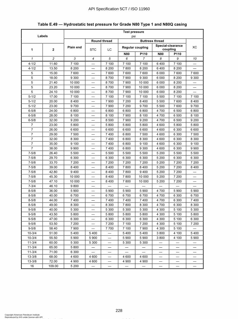
ISO 11960:2004(E)
228 © ISO 2004 – All rights reserved
Table E.49 — Hydrostatic test pressure for Grade N80 Type 1 and N80Q casing
Test pressure psi Labels
Round thread Buttress thread
Regular coupling Special-clearance coupling 1 2
Plain end STC LC
N80 P110 N80 P110
XC
1 2 3 4 5 6 7 8 9 10 4-1/2 11.60 7 100 — 7 100 7 100 7 100 6 400 7 100 — 4-1/2 13.50 8 200 — 8 200 7 800 8 200 6 400 8 200 —
5 15.00 7 600 — 7 600 7 600 7 600 6 000 7 600 7 600 5 18.00 9 300 — 8 700 7 900 9 300 6 000 8 200 9 300 5 21.40 10 000 — 8 700 7 900 10 000 6 000 8 200 — 5 23.20 10 000 — 8 700 7 900 10 000 6 000 8 200 — 5 24.10 10 000 — 8 700 7 900 10 000 6 000 8 200 —
5-1/2 17.00 7 100 — 7 100 7 100 7 100 5 500 7 100 7 100 5-1/2 20.00 8 400 — 7 900 7 200 8 400 5 500 7 600 8 400 5-1/2 23.00 9 700 — 7 900 7 200 9 700 5 500 7 600 9 700 6-5/8 24.00 6 800 — 6 800 6 800 6 800 4 700 6 500 6 800 6-5/8 28.00 8 100 — 8 100 7 900 8 100 4 700 6 500 8 100 6-5/8 32.00 9 200 — 8 500 7 900 9 200 4 700 6 500 9 200
7 23.00 5 800 — 5 800 5 800 5 800 4 600 5 800 5 800 7 26.00 6 600 — 6 600 6 600 6 600 4 600 6 300 6 600 7 29.00 7 500 — 7 400 6 800 7 500 4 600 6 300 7 500 7 32.00 8 300 — 7 400 6 800 8 300 4 600 6 300 8 300 7 35.00 9 100 — 7 400 6 800 9 100 4 600 6 300 9 100 7 38.00 9 900 — 7 400 6 800 9 300 4 600 6 300 9 900
7-5/8 26.40 5 500 — 5 500 5 500 5 500 5 200 5 500 5 500 7-5/8 29.70 6 300 — 6 300 6 300 6 300 5 200 6 300 6 300 7-5/8 33.70 7 200 — 7 200 7 200 7 200 5 200 7 200 7 200 7-5/8 39.00 8 400 — 8 400 7 800 8 400 5 200 7 200 8 400 7-5/8 42.80 9 400 — 8 400 7 800 9 400 5 200 7 200 — 7-5/8 45.30 10 000 — 8 400 7 800 10 000 5 200 7 200 — 7-5/8 47.10 10 000 — 8 400 7 800 10 000 5 200 7 200 — 7-3/4 46.10 9 800 — — — — — — — 8-5/8 36.00 5 900 — 5 900 5 900 5 900 4 700 5 900 5 900 8-5/8 40.00 6 700 — 6 700 6 700 6 700 4 700 6 300 6 700 8-5/8 44.00 7 400 — 7 400 7 400 7 400 4 700 6 300 7 400 8-5/8 49.00 8 300 — 8 300 7 800 8 300 4 700 6 300 8 300 9-5/8 40.00 5 300 — 5 300 5 300 5 300 4 300 5 100 5 300 9-5/8 43.50 5 800 — 5 800 5 800 5 800 4 300 5 100 5 800 9-5/8 47.00 6 300 — 6 300 6 300 6 300 4 300 5 100 6 300 9-5/8 53.50 7 200 — 7 200 7 100 7 200 4 300 5 100 7 200 9-5/8 58.40 7 900 — 7 700 7 100 7 900 4 300 5 100 —
10-3/4 51.00 5 400 5 400 — 5 400 5 400 3 800 4 100 5 400 10-3/4 55.50 5 900 5 900 — 5 900 5 900 3 800 4 100 5 900 11-3/4 60.00 5 300 5 300 — 5 300 5 300 — — — 11-3/4 65.00 5 800 — — — — — — — 11-3/4 71.00 6 300 — — — — — — — 13-3/8 68.00 4 600 4 600 — 4 600 4 600 — — — 13-3/8 72.00 4 900 4 600 — 4 900 4 900 — — —
16 109.00 5 200 — — — — — — —
API Specification 5CT / ISO 11960
228Copyright American Petroleum Institute Reproduced by IHS under license with API
Not for ResaleNo reproduction or networking permitted without license from IHS
--`,,,```-`-`,,`,,`,`,,`---
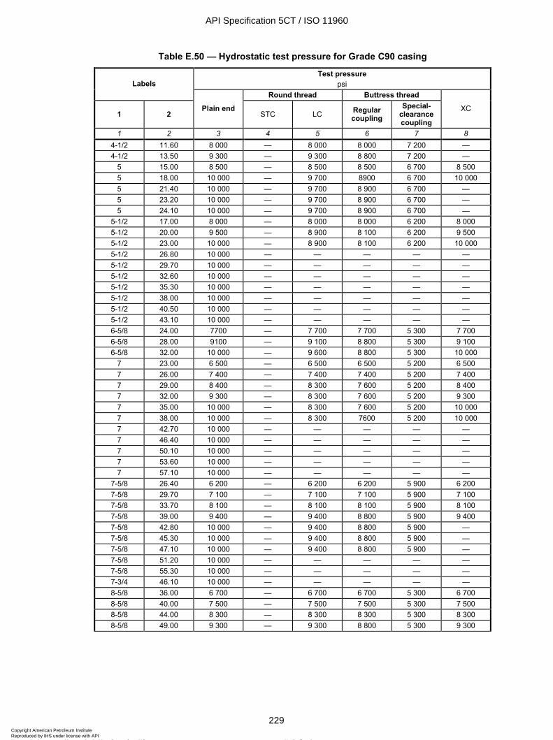
ISO 11960:2004(E)
© ISO 2004 – All rights reserved 229
Table E.50 — Hydrostatic test pressure for Grade C90 casing
Test pressure psi Labels
Round thread Buttress thread
1 2 Plain end
STC LC Regular coupling
Special-clearance coupling
XC
1 2 3 4 5 6 7 8 4-1/2 11.60 8 000 — 8 000 8 000 7 200 — 4-1/2 13.50 9 300 — 9 300 8 800 7 200 —
5 15.00 8 500 — 8 500 8 500 6 700 8 500 5 18.00 10 000 — 9 700 8900 6 700 10 000 5 21.40 10 000 — 9 700 8 900 6 700 — 5 23.20 10 000 — 9 700 8 900 6 700 — 5 24.10 10 000 — 9 700 8 900 6 700 —
5-1/2 17.00 8 000 — 8 000 8 000 6 200 8 000 5-1/2 20.00 9 500 — 8 900 8 100 6 200 9 500 5-1/2 23.00 10 000 — 8 900 8 100 6 200 10 000 5-1/2 26.80 10 000 — — — — — 5-1/2 29.70 10 000 — — — — — 5-1/2 32.60 10 000 — — — — — 5-1/2 35.30 10 000 — — — — — 5-1/2 38.00 10 000 — — — — — 5-1/2 40.50 10 000 — — — — — 5-1/2 43.10 10 000 — — — — — 6-5/8 24.00 7700 — 7 700 7 700 5 300 7 700 6-5/8 28.00 9100 — 9 100 8 800 5 300 9 100 6-5/8 32.00 10 000 — 9 600 8 800 5 300 10 000
7 23.00 6 500 — 6 500 6 500 5 200 6 500 7 26.00 7 400 — 7 400 7 400 5 200 7 400 7 29.00 8 400 — 8 300 7 600 5 200 8 400 7 32.00 9 300 — 8 300 7 600 5 200 9 300 7 35.00 10 000 — 8 300 7 600 5 200 10 000 7 38.00 10 000 — 8 300 7600 5 200 10 000 7 42.70 10 000 — — — — — 7 46.40 10 000 — — — — — 7 50.10 10 000 — — — — — 7 53.60 10 000 — — — — — 7 57.10 10 000 — — — — —
7-5/8 26.40 6 200 — 6 200 6 200 5 900 6 200 7-5/8 29.70 7 100 — 7 100 7 100 5 900 7 100 7-5/8 33.70 8 100 — 8 100 8 100 5 900 8 100 7-5/8 39.00 9 400 — 9 400 8 800 5 900 9 400 7-5/8 42.80 10 000 — 9 400 8 800 5 900 — 7-5/8 45.30 10 000 — 9 400 8 800 5 900 — 7-5/8 47.10 10 000 — 9 400 8 800 5 900 — 7-5/8 51.20 10 000 — — — — — 7-5/8 55.30 10 000 — — — — — 7-3/4 46.10 10 000 — — — — — 8-5/8 36.00 6 700 — 6 700 6 700 5 300 6 700 8-5/8 40.00 7 500 — 7 500 7 500 5 300 7 500 8-5/8 44.00 8 300 — 8 300 8 300 5 300 8 300 8-5/8 49.00 9 300 — 9 300 8 800 5 300 9 300
API Specification 5CT / ISO 11960
229Copyright American Petroleum Institute Reproduced by IHS under license with API
Not for ResaleNo reproduction or networking permitted without license from IHS
--`,,,```-`-`,,`,,`,`,,`---

ISO 11960:2004(E)
230 © ISO 2004 – All rights reserved
Table E.50 (continued)
Test pressure psi Labels
Round thread Buttress thread
1 2 Plain end
STC LC Regular coupling
Special-clearance coupling
XC
1 2 3 4 5 6 7 8 9-5/8 40.00 5 900 — 5 900 5 900 4 800 5 900 9-5/8 43.50 6 500 — 6 500 6 500 4 800 6 500 9-5/8 47.00 7 100 — 7 100 7 100 4 800 7 100 9-5/8 53.50 8 200 — 8 200 7 900 4 800 8 200 9-5/8 58.40 8 900 — 8 500 7 900 4 800 — 9-5/8 59.40 9 100 — — — — — 9-5/8 64.90 10 000 — — — — — 9-5/8 70.30 10 000 — — — — — 9-5/8 75.60 10 000 — — — — —
10-3/4 51.00 6 000 6 000 — 6 000 4 100 6 000 10-3/4 55.50 6 600 6 600 — 6 600 4 100 6 600 10-3/4 60.70 7 300 6 900 — 7 200 4 100 7 300 10-3/4 65.70 8 000 6 900 — 7 200 4 100 — 10-3/4 73.20 9 000 — — — — — 10-3/4 79.20 9 800 — — — — — 10-3/4 85.30 10 000 — — — — — 11-3/4 60.00 6 000 5 800 — 6 000 — — 11-3/4 65.00 6 500 — — — — — 11-3/4 71.00 7 100 — — — — — 13-3/8 68.00 5 200 4 600 — 4 900 — — 13-3/8 72.00 5 500 4 600 — 4 900 — —
API Specification 5CT / ISO 11960
230Copyright American Petroleum Institute Reproduced by IHS under license with API
Not for ResaleNo reproduction or networking permitted without license from IHS
--`,,,```-`-`,,`,,`,`,,`---

ISO 11960:2004(E)
© ISO 2004 – All rights reserved 231
Table E.51 — Hydrostatic test pressure for Grade C95 casing
Test pressure psi Labels
Round thread Buttress thread
1 2 Plain end
STC LC Regular coupling
Special-clearance coupling
XC
1 2 3 4 5 6 7 8 4-1/2 11.60 8 400 — 8 400 8 400 7 600 — 4-1/2 13.50 9 800 — 9 800 9 300 7 600 —
5 15.00 9 000 — 9 000 9 000 7 100 9 000 5 18.00 10 000 — 10 000 9 400 7 100 10 000 5 21.40 10 000 — 10 000 9 400 7 100 — 5 23.20 10 000 — 10 000 9 400 7 100 — 5 24.10 10 000 — 10 000 9 400 7 100 —
5-1/2 17.00 8 400 — 8 400 8 400 6 500 8 400 5-1/2 20.00 10 000 — 9 400 8 500 6 500 10 000 5-1/2 23.00 10 000 — 9 400 8 500 6 500 10 000 6-5/8 24.00 8 100 — 8 100 8 100 5 600 8 100 6-5/8 28.00 9 600 — 9 600 9 300 5 600 9 600 6-5/8 32.00 10 000 — 10 000 9 300 5 600 10 000
7 23.00 6 900 — 6 900 6 900 5 500 6 900 7 26.00 7 900 — 7 900 7 900 5 500 7 900 7 29.00 8 900 — 8 800 8 000 5 500 8 900 7 32.00 9 800 — 8 800 8 000 5 500 9 800 7 35.00 10 000 — 8 800 8 000 5 500 10 000 7 38.00 10 000 — 8 800 8 000 5 500 10 000
7-5/8 26.40 6 500 — 6 500 6 500 6 200 6 500 7-5/8 29.70 7 500 — 7 500 7 500 6 200 7 500 7-5/8 33.70 8 600 — 8 600 8 600 6 200 8 600 7-5/8 39.00 10 000 — 10 000 9 300 6 200 10 000 7-5/8 42.80 10 000 — 10 000 9 300 6 200 — 7-5/8 45.30 10 000 — 10 000 9 300 6 200 — 7-5/8 47.10 10 000 — 10 000 9 300 6 200 — 7-3/4 46.10 10 000 — — — — — 8-5/8 36.00 7 000 — 7 000 7 000 5 600 7 000 8-5/8 40.00 7 900 — 7 900 7 900 5 600 7 900 8-5/8 44.00 8 800 — 8 800 8 800 5 600 8 800 8-5/8 49.00 9 800 — 9 800 9 300 5 600 9 800 9-5/8 40.00 6 200 — 6 200 6 200 5 100 6 200 9-5/8 43.50 6 900 — 6 900 6 900 5 100 6 900 9-5/8 47.00 7 500 — 7 500 7 500 5 100 7 500 9-5/8 53.50 8 600 — 8 500 8 400 5 100 8 600 9-5/8 58.40 9 400 — 8 500 8 400 5 100 —
10-3/4 51.00 6 400 6 400 — 6 400 4 100 6 400 10-3/4 55.50 7 000 6 900 — 7 000 4 100 7 000 11-3/4 60.00 6 300 5 800 — 6 300 — — 11-3/4 65.00 6 900 — — — — — 11-3/4 71.00 7 500 — — — — — 13-3/8 68.00 5 500 4 600 — 4 900 — — 13-3/8 72.00 5 800 4 600 — 4 900 — —
16 109.00 6 200 — — — — —
API Specification 5CT / ISO 11960
231Copyright American Petroleum Institute Reproduced by IHS under license with API
Not for ResaleNo reproduction or networking permitted without license from IHS
--`,,,```-`-`,,`,,`,`,,`---
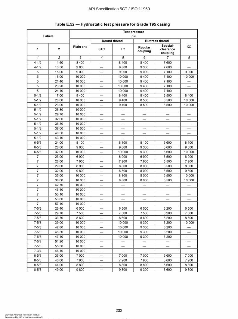
ISO 11960:2004(E)
232 © ISO 2004 – All rights reserved
Table E.52 — Hydrostatic test pressure for Grade T95 casing
Test pressure psi Labels
Round thread Buttress thread
1 2 Plain end
STC LC Regular coupling
Special-clearance coupling
XC
1 2 3 4 5 6 7 8 4-1/2 11.60 8 400 — 8 400 8 400 7 600 — 4-1/2 13.50 9 800 — 9 800 9 300 7 600 —
5 15.00 9 000 — 9 000 9 000 7 100 9 000 5 18.00 10 000 — 10 000 9 400 7 100 10 000 5 21.40 10 000 — 10 000 9 400 7 100 — 5 23.20 10 000 — 10 000 9 400 7 100 — 5 24.10 10 000 — 10 000 9 400 7 100 —
5-1/2 17.00 8 400 — 8 400 8 400 6 500 8 400 5-1/2 20.00 10 000 — 9 400 8 500 6 500 10 000 5-1/2 23.00 10 000 — 9 400 8 500 6 500 10 000 5-1/2 26.80 10 000 — — — — — 5-1/2 29.70 10 000 — — — — — 5-1/2 32.60 10 000 — — — — — 5-1/2 35.30 10 000 — — — — — 5-1/2 38.00 10 000 — — — — — 5-1/2 40.50 10 000 — — — — — 5-1/2 43.10 10 000 — — — — — 6-5/8 24.00 8 100 — 8 100 8 100 5 600 8 100 6-5/8 28.00 9 600 — 9 600 9 300 5 600 9 600 6-5/8 32.00 10 000 — 10 000 9 300 5 600 10 000
7 23.00 6 900 — 6 900 6 900 5 500 6 900 7 26.00 7 900 — 7 900 7 900 5 500 7 900 7 29.00 8 900 — 8 800 8 000 5 500 8 800 7 32.00 9 800 — 8 800 8 000 5 500 9 800 7 35.00 10 000 — 8 800 8 000 5 500 10 000 7 38.00 10 000 — 8 800 8 000 5 500 10 000 7 42.70 10 000 — — — — — 7 46.40 10 000 — — — — — 7 50.10 10 000 — — — — — 7 53.60 10 000 — — — — — 7 57.10 10 000 — — — — —
7-5/8 26.40 6 500 — 6 500 6 500 6 200 6 500 7-5/8 29.70 7 500 — 7 500 7 500 6 200 7 500 7-5/8 33.70 8 600 — 8 600 8 600 6 200 8 600 7-5/8 39.00 10 000 — 10 000 9 300 6 200 10 000 7-5/8 42.80 10 000 — 10 000 9 300 6 200 — 7-5/8 45.30 10 000 — 10 000 9 300 6 200 — 7-5/8 47.10 10 000 — 10 000 9 300 6 200 — 7-5/8 51.20 10 000 — — — — — 7-5/8 55.30 10 000 — — — — — 7-3/4 46.10 10 000 — — — — — 8-5/8 36.00 7 000 — 7 000 7 000 5 600 7 000 8-5/8 40.00 7 900 — 7 900 7 900 5 600 7 900 8-5/8 44.00 8 800 — 8 800 8 800 5 600 8 800 8-5/8 49.00 9 800 — 9 800 9 300 5 600 9 800
API Specification 5CT / ISO 11960
232Copyright American Petroleum Institute Reproduced by IHS under license with API
Not for ResaleNo reproduction or networking permitted without license from IHS
--`,,,```-`-`,,`,,`,`,,`---
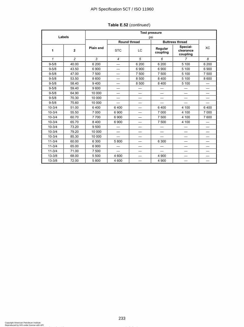
ISO 11960:2004(E)
© ISO 2004 – All rights reserved 233
Table E.52 (continued)
Test pressure psi Labels
Round thread Buttress thread
1 2 Plain end
STC LC Regular coupling
Special-clearance coupling
XC
1 2 3 4 5 6 7 8 9-5/8 40.00 6 200 — 6 200 6 200 5 100 6 200 9-5/8 43.50 6 900 — 6 900 6 900 5 100 6 900 9-5/8 47.00 7 500 — 7 500 7 500 5 100 7 500 9-5/8 53.50 8 600 — 8 500 8 400 5 100 8 600 9-5/8 58.40 9 400 — 8 500 8 400 5 100 — 9-5/8 59.40 9 600 — — — — — 9-5/8 64.90 10 000 — — — — — 9-5/8 70.30 10 000 — — — — — 9-5/8 75.60 10 000 — — — — —
10-3/4 51.00 6 400 6 400 — 6 400 4 100 6 400 10-3/4 55.50 7 000 6 900 — 7 000 4 100 7 000 10-3/4 60.70 7 700 6 900 — 7 500 4 100 7 600 10-3/4 65.70 8 400 6 900 — 7 500 4 100 — 10-3/4 73.20 9 500 — — — — — 10-3/4 79.20 10 000 — — — — — 10-3/4 85.30 10 000 — — — — — 11-3/4 60.00 6 300 5 800 — 6 300 — — 11-3/4 65.00 6 900 — — — — — 11-3/4 71.00 7 500 — — — — — 13-3/8 68.00 5 500 4 600 — 4 900 — — 13-3/8 72.00 5 800 4 600 — 4 900 — —
API Specification 5CT / ISO 11960
233Copyright American Petroleum Institute Reproduced by IHS under license with API
Not for ResaleNo reproduction or networking permitted without license from IHS
--`,,,```-`-`,,`,,`,`,,`---
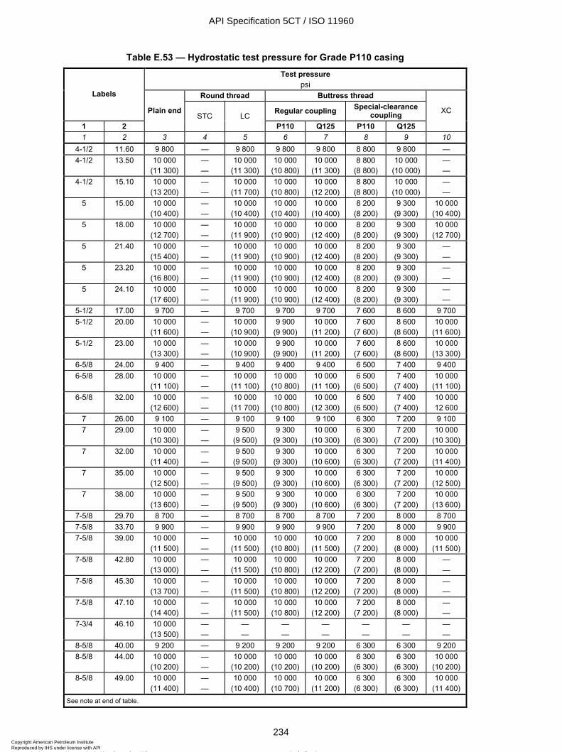
ISO 11960:2004(E)
234 © ISO 2004 – All rights reserved
Table E.53 — Hydrostatic test pressure for Grade P110 casing Test pressure
psi Round thread Buttress thread Labels
Regular coupling Special-clearance coupling
1 2
Plain endSTC LC
P110 Q125 P110 Q125
XC
1 2 3 4 5 6 7 8 9 10 4-1/2 11.60 9 800 — 9 800 9 800 9 800 8 800 9 800 — 4-1/2 13.50 10 000
(11 300) — —
10 000 (11 300)
10 000 (10 800)
10 000 (11 300)
8 800 (8 800)
10 000 (10 000)
— —
4-1/2 15.10 10 000 (13 200)
— —
10 000 (11 700)
10 000 (10 800)
10 000 (12 200)
8 800 (8 800)
10 000 (10 000)
— —
5 15.00 10 000 (10 400)
— —
10 000 (10 400)
10 000 (10 400)
10 000 (10 400)
8 200 (8 200)
9 300 (9 300)
10 000 (10 400)
5 18.00 10 000 (12 700)
— —
10 000 (11 900)
10 000 (10 900)
10 000 (12 400)
8 200 (8 200)
9 300 (9 300)
10 000 (12 700)
5 21.40 10 000 (15 400)
— —
10 000 (11 900)
10 000 (10 900)
10 000 (12 400)
8 200 (8 200)
9 300 (9 300)
— —
5 23.20 10 000 (16 800)
— —
10 000 (11 900)
10 000 (10 900)
10 000 (12 400)
8 200 (8 200)
9 300 (9 300)
— —
5 24.10 10 000 (17 600)
— —
10 000 (11 900)
10 000 (10 900)
10 000 (12 400)
8 200 (8 200)
9 300 (9 300)
— —
5-1/2 17.00 9 700 — 9 700 9 700 9 700 7 600 8 600 9 700 5-1/2 20.00 10 000
(11 600) — —
10 000 (10 900)
9 900 (9 900)
10 000 (11 200)
7 600 (7 600)
8 600 (8 600)
10 000 (11 600)
5-1/2 23.00 10 000 (13 300)
— —
10 000 (10 900)
9 900 (9 900)
10 000 (11 200)
7 600 (7 600)
8 600 (8 600)
10 000 (13 300)
6-5/8 24.00 9 400 — 9 400 9 400 9 400 6 500 7 400 9 400 6-5/8 28.00 10 000
(11 100) — —
10 000 (11 100)
10 000 (10 800)
10 000 (11 100)
6 500 (6 500)
7 400 (7 400)
10 000 (11 100)
6-5/8 32.00 10 000 (12 600)
— —
10 000 (11 700)
10 000 (10 800)
10 000 (12 300)
6 500 (6 500)
7 400 (7 400)
10 000 12 600
7 26.00 9 100 — 9 100 9 100 9 100 6 300 7 200 9 100 7 29.00 10 000
(10 300) — —
9 500 (9 500)
9 300 (9 300)
10 000 (10 300)
6 300 (6 300)
7 200 (7 200)
10 000 (10 300)
7 32.00 10 000 (11 400)
— —
9 500 (9 500)
9 300 (9 300)
10 000 (10 600)
6 300 (6 300)
7 200 (7 200)
10 000 (11 400)
7 35.00 10 000 (12 500)
— —
9 500 (9 500)
9 300 (9 300)
10 000 (10 600)
6 300 (6 300)
7 200 (7 200)
10 000 (12 500)
7 38.00 10 000 (13 600)
— —
9 500 (9 500)
9 300 (9 300)
10 000 (10 600)
6 300 (6 300)
7 200 (7 200)
10 000 (13 600)
7-5/8 29.70 8 700 — 8 700 8 700 8 700 7 200 8 000 8 700 7-5/8 33.70 9 900 — 9 900 9 900 9 900 7 200 8 000 9 900 7-5/8 39.00 10 000
(11 500) — —
10 000 (11 500)
10 000 (10 800)
10 000 (11 500)
7 200 (7 200)
8 000 (8 000)
10 000 (11 500)
7-5/8 42.80 10 000 (13 000)
— —
10 000 (11 500)
10 000 (10 800)
10 000 (12 200)
7 200 (7 200)
8 000 (8 000)
— —
7-5/8 45.30 10 000 (13 700)
— —
10 000 (11 500)
10 000 (10 800)
10 000 (12 200)
7 200 (7 200)
8 000 (8 000)
— —
7-5/8 47.10 10 000 (14 400)
— —
10 000 (11 500)
10 000 (10 800)
10 000 (12 200)
7 200 (7 200)
8 000 (8 000)
— —
7-3/4 46.10 10 000 (13 500)
— —
— —
— —
— —
— —
— —
— —
8-5/8 40.00 9 200 — 9 200 9 200 9 200 6 300 6 300 9 200 8-5/8 44.00 10 000
(10 200) — —
10 000 (10 200)
10 000 (10 200)
10 000 (10 200)
6 300 (6 300)
6 300 (6 300)
10 000 (10 200)
8-5/8 49.00 10 000 (11 400)
— —
10 000 (10 400)
10 000 (10 700)
10 000 (11 200)
6 300 (6 300)
6 300 (6 300)
10 000 (11 400)
See note at end of table.
API Specification 5CT / ISO 11960
234Copyright American Petroleum Institute Reproduced by IHS under license with API
Not for ResaleNo reproduction or networking permitted without license from IHS
--`,,,```-`-`,,`,,`,`,,`---
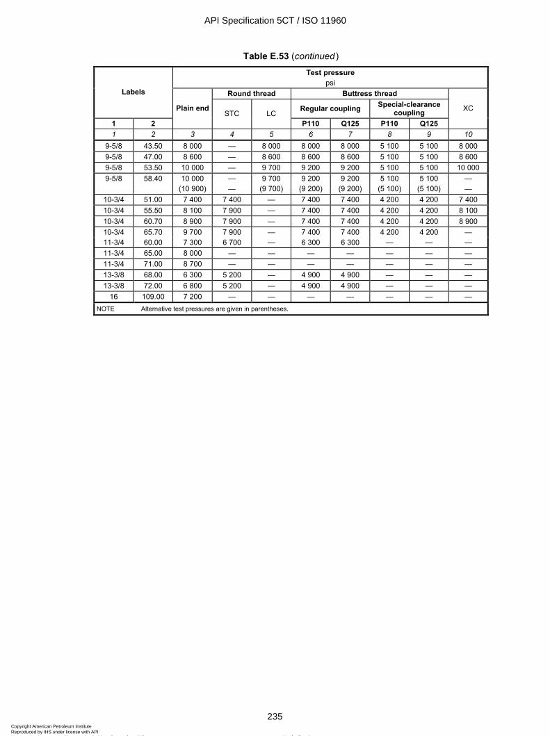
ISO 11960:2004(E)
© ISO 2004 – All rights reserved 235
Table E.53 (continued) Test pressure
psi Round thread Buttress thread Labels
Regular coupling Special-clearance coupling
1 2
Plain end STC LC
P110 Q125 P110 Q125
XC
1 2 3 4 5 6 7 8 9 10 9-5/8 43.50 8 000 — 8 000 8 000 8 000 5 100 5 100 8 000 9-5/8 47.00 8 600 — 8 600 8 600 8 600 5 100 5 100 8 600 9-5/8 53.50 10 000 — 9 700 9 200 9 200 5 100 5 100 10 000 9-5/8 58.40 10 000
(10 900) — —
9 700 (9 700)
9 200 (9 200)
9 200 (9 200)
5 100 (5 100)
5 100 (5 100)
— —
10-3/4 51.00 7 400 7 400 — 7 400 7 400 4 200 4 200 7 400 10-3/4 55.50 8 100 7 900 — 7 400 7 400 4 200 4 200 8 100 10-3/4 60.70 8 900 7 900 — 7 400 7 400 4 200 4 200 8 900 10-3/4 65.70 9 700 7 900 — 7 400 7 400 4 200 4 200 — 11-3/4 60.00 7 300 6 700 — 6 300 6 300 — — — 11-3/4 65.00 8 000 — — — — — — — 11-3/4 71.00 8 700 — — — — — — — 13-3/8 68.00 6 300 5 200 — 4 900 4 900 — — — 13-3/8 72.00 6 800 5 200 — 4 900 4 900 — — —
16 109.00 7 200 — — — — — — — NOTE Alternative test pressures are given in parentheses.
API Specification 5CT / ISO 11960
235Copyright American Petroleum Institute Reproduced by IHS under license with API
Not for ResaleNo reproduction or networking permitted without license from IHS
--`,,,```-`-`,,`,,`,`,,`---
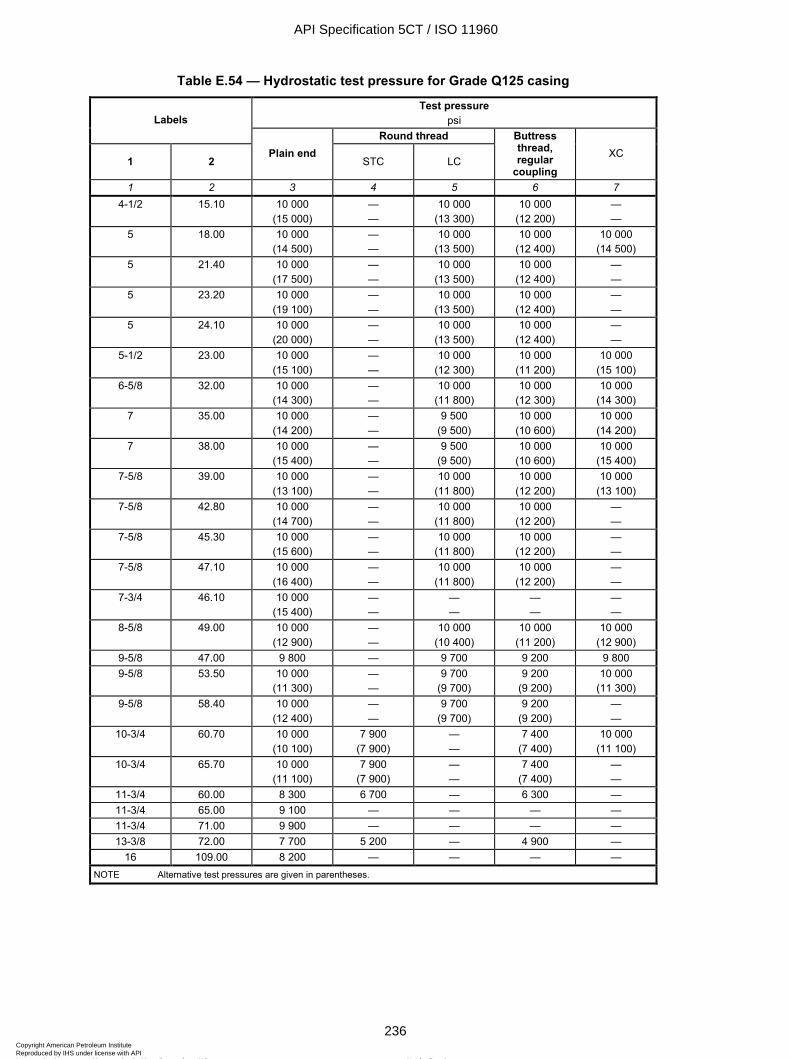
ISO 11960:2004(E)
236 © ISO 2004 – All rights reserved
Table E.54 — Hydrostatic test pressure for Grade Q125 casing
Test pressure psi Labels
Round thread
1 2 Plain end
STC LC
Buttress thread, regular
coupling XC
1 2 3 4 5 6 7 4-1/2 15.10 10 000
(15 000) — —
10 000 (13 300)
10 000 (12 200)
— —
5 18.00 10 000 (14 500)
— —
10 000 (13 500)
10 000 (12 400)
10 000 (14 500)
5 21.40 10 000 (17 500)
— —
10 000 (13 500)
10 000 (12 400)
— —
5 23.20 10 000 (19 100)
— —
10 000 (13 500)
10 000 (12 400)
— —
5 24.10 10 000 (20 000)
— —
10 000 (13 500)
10 000 (12 400)
— —
5-1/2 23.00 10 000 (15 100)
— —
10 000 (12 300)
10 000 (11 200)
10 000 (15 100)
6-5/8 32.00 10 000 (14 300)
— —
10 000 (11 800)
10 000 (12 300)
10 000 (14 300)
7 35.00 10 000 (14 200)
— —
9 500 (9 500)
10 000 (10 600)
10 000 (14 200)
7 38.00 10 000 (15 400)
— —
9 500 (9 500)
10 000 (10 600)
10 000 (15 400)
7-5/8 39.00 10 000 (13 100)
— —
10 000 (11 800)
10 000 (12 200)
10 000 (13 100)
7-5/8 42.80 10 000 (14 700)
— —
10 000 (11 800)
10 000 (12 200)
— —
7-5/8 45.30 10 000 (15 600)
— —
10 000 (11 800)
10 000 (12 200)
— —
7-5/8 47.10 10 000 (16 400)
— —
10 000 (11 800)
10 000 (12 200)
— —
7-3/4 46.10 10 000 (15 400)
— —
— —
— —
— —
8-5/8 49.00 10 000 (12 900)
— —
10 000 (10 400)
10 000 (11 200)
10 000 (12 900)
9-5/8 47.00 9 800 — 9 700 9 200 9 800 9-5/8 53.50 10 000
(11 300) — —
9 700 (9 700)
9 200 (9 200)
10 000 (11 300)
9-5/8 58.40 10 000 (12 400)
— —
9 700 (9 700)
9 200 (9 200)
— —
10-3/4 60.70 10 000 (10 100)
7 900 (7 900)
— —
7 400 (7 400)
10 000 (11 100)
10-3/4 65.70 10 000 (11 100)
7 900 (7 900)
— —
7 400 (7 400)
— —
11-3/4 60.00 8 300 6 700 — 6 300 — 11-3/4 65.00 9 100 — — — — 11-3/4 71.00 9 900 — — — — 13-3/8 72.00 7 700 5 200 — 4 900 —
16 109.00 8 200 — — — — NOTE Alternative test pressures are given in parentheses.
API Specification 5CT / ISO 11960
236Copyright American Petroleum Institute Reproduced by IHS under license with API
Not for ResaleNo reproduction or networking permitted without license from IHS
--`,,,```-`-`,,`,,`,`,,`---
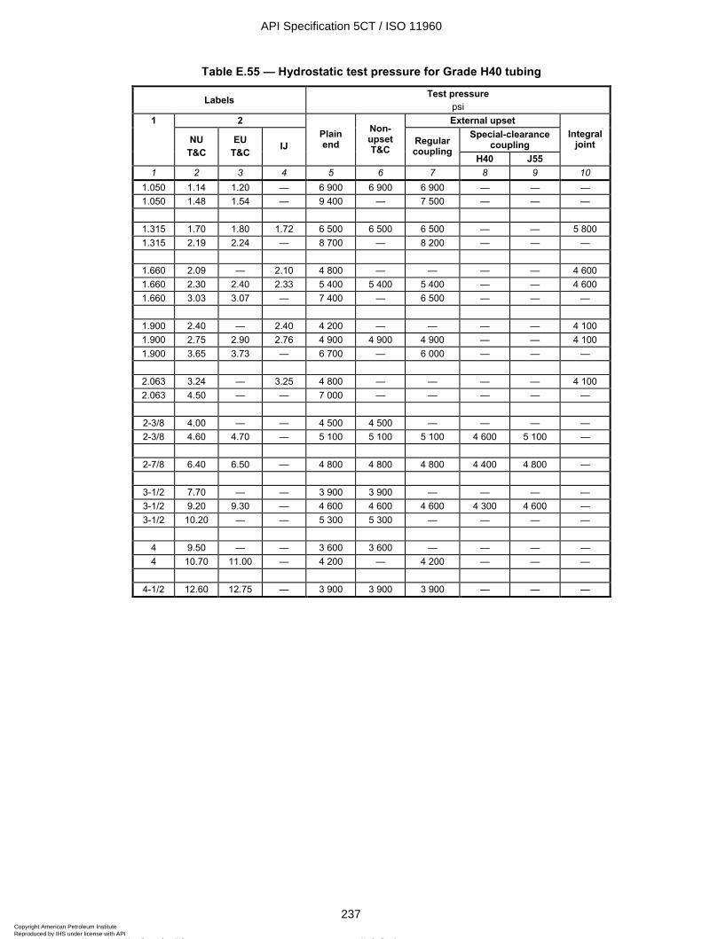
ISO 11960:2004(E)
© ISO 2004 – All rights reserved 237
Table E.55 — Hydrostatic test pressure for Grade H40 tubing
Labels Test pressure psi
2 External upset Special-clearance
coupling
1
NU T&C
EU T&C
IJ Plain end
Non-upset T&C
Regular coupling
H40 J55
Integral joint
1 2 3 4 5 6 7 8 9 10 1.050 1.14 1.20 — 6 900 6 900 6 900 — — — 1.050 1.48 1.54 — 9 400 — 7 500 — — —
1.315 1.70 1.80 1.72 6 500 6 500 6 500 — — 5 800 1.315 2.19 2.24 — 8 700 — 8 200 — — —
1.660 2.09 — 2.10 4 800 — — — — 4 600 1.660 2.30 2.40 2.33 5 400 5 400 5 400 — — 4 600 1.660 3.03 3.07 — 7 400 — 6 500 — — —
1.900 2.40 — 2.40 4 200 — — — — 4 100 1.900 2.75 2.90 2.76 4 900 4 900 4 900 — — 4 100 1.900 3.65 3.73 — 6 700 — 6 000 — — —
2.063 3.24 — 3.25 4 800 — — — — 4 100 2.063 4.50 — — 7 000 — — — — —
2-3/8 4.00 — — 4 500 4 500 — — — — 2-3/8 4.60 4.70 — 5 100 5 100 5 100 4 600 5 100 —
2-7/8 6.40 6.50 — 4 800 4 800 4 800 4 400 4 800 —
3-1/2 7.70 — — 3 900 3 900 — — — — 3-1/2 9.20 9.30 — 4 600 4 600 4 600 4 300 4 600 — 3-1/2 10.20 — — 5 300 5 300 — — — —
4 9.50 — — 3 600 3 600 — — — — 4 10.70 11.00 — 4 200 — 4 200 — — —
4-1/2 12.60 12.75 — 3 900 3 900 3 900 — — —
API Specification 5CT / ISO 11960
237Copyright American Petroleum Institute Reproduced by IHS under license with API
Not for ResaleNo reproduction or networking permitted without license from IHS
--`,,,```-`-`,,`,,`,`,,`---
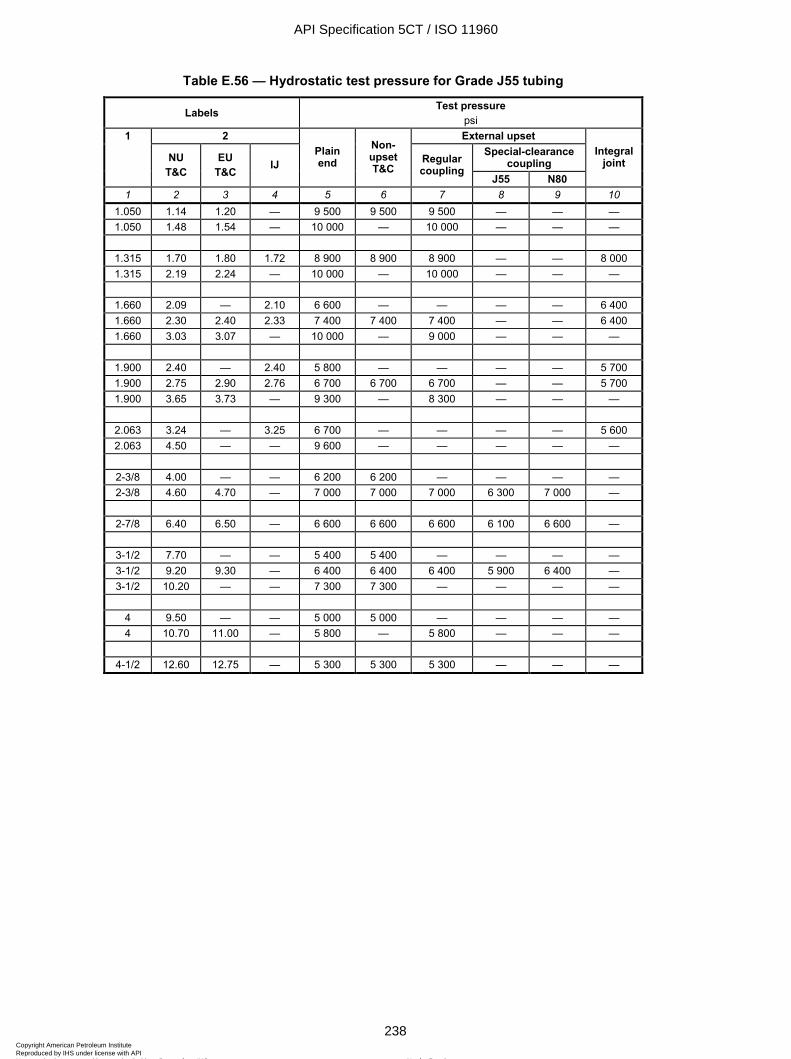
ISO 11960:2004(E)
238 © ISO 2004 – All rights reserved
Table E.56 — Hydrostatic test pressure for Grade J55 tubing
Labels Test pressure psi
2 External upset Special-clearance
coupling
1
NU T&C
EU T&C
IJ Plain end
Non-upset T&C
Regular coupling
J55 N80
Integral joint
1 2 3 4 5 6 7 8 9 10 1.050 1.14 1.20 — 9 500 9 500 9 500 — — — 1.050 1.48 1.54 — 10 000 — 10 000 — — —
1.315 1.70 1.80 1.72 8 900 8 900 8 900 — — 8 000 1.315 2.19 2.24 — 10 000 — 10 000 — — —
1.660 2.09 — 2.10 6 600 — — — — 6 400 1.660 2.30 2.40 2.33 7 400 7 400 7 400 — — 6 400 1.660 3.03 3.07 — 10 000 — 9 000 — — —
1.900 2.40 — 2.40 5 800 — — — — 5 700 1.900 2.75 2.90 2.76 6 700 6 700 6 700 — — 5 700 1.900 3.65 3.73 — 9 300 — 8 300 — — —
2.063 3.24 — 3.25 6 700 — — — — 5 600 2.063 4.50 — — 9 600 — — — — —
2-3/8 4.00 — — 6 200 6 200 — — — — 2-3/8 4.60 4.70 — 7 000 7 000 7 000 6 300 7 000 —
2-7/8 6.40 6.50 — 6 600 6 600 6 600 6 100 6 600 —
3-1/2 7.70 — — 5 400 5 400 — — — — 3-1/2 9.20 9.30 — 6 400 6 400 6 400 5 900 6 400 — 3-1/2 10.20 — — 7 300 7 300 — — — —
4 9.50 — — 5 000 5 000 — — — — 4 10.70 11.00 — 5 800 — 5 800 — — —
4-1/2 12.60 12.75 — 5 300 5 300 5 300 — — —
API Specification 5CT / ISO 11960
238Copyright American Petroleum Institute Reproduced by IHS under license with API
Not for ResaleNo reproduction or networking permitted without license from IHS
--`,,,```-`-`,,`,,`,`,,`---
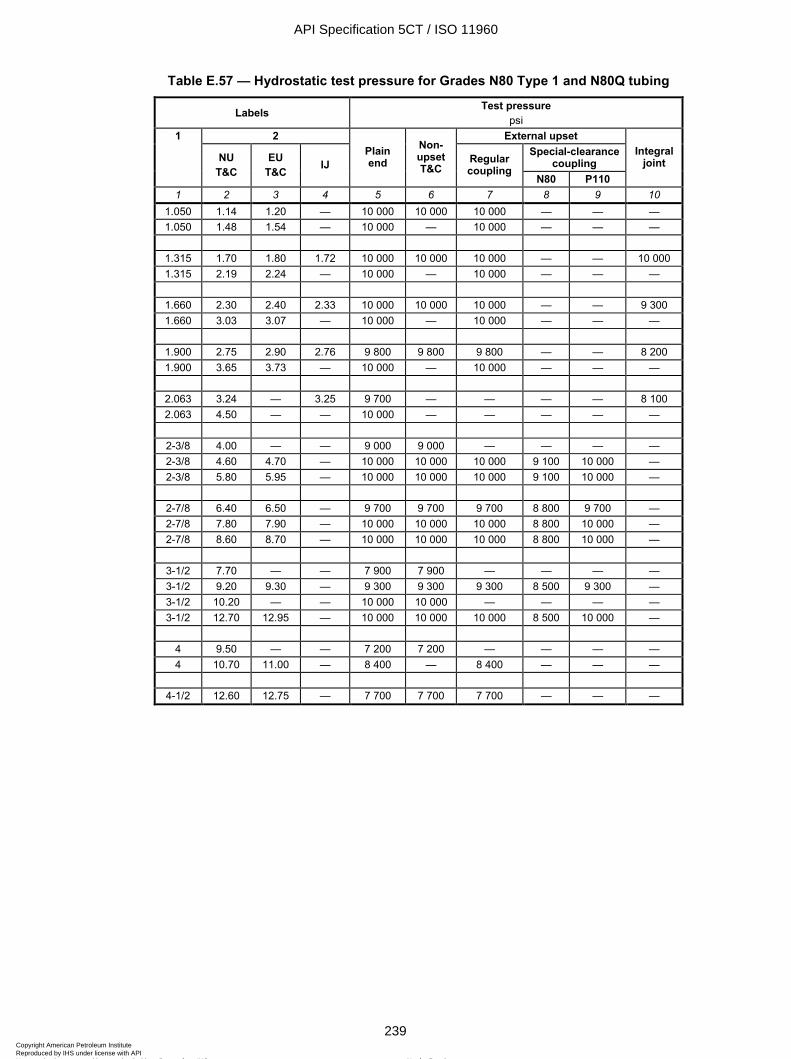
ISO 11960:2004(E)
© ISO 2004 – All rights reserved 239
Table E.57 — Hydrostatic test pressure for Grades N80 Type 1 and N80Q tubing
Labels Test pressure psi
2 External upset Special-clearance
coupling
1
NU T&C
EU T&C
IJ Plain end
Non-upset T&C
Regular coupling
N80 P110
Integral joint
1 2 3 4 5 6 7 8 9 10 1.050 1.14 1.20 — 10 000 10 000 10 000 — — — 1.050 1.48 1.54 — 10 000 — 10 000 — — —
1.315 1.70 1.80 1.72 10 000 10 000 10 000 — — 10 000 1.315 2.19 2.24 — 10 000 — 10 000 — — —
1.660 2.30 2.40 2.33 10 000 10 000 10 000 — — 9 300 1.660 3.03 3.07 — 10 000 — 10 000 — — —
1.900 2.75 2.90 2.76 9 800 9 800 9 800 — — 8 200 1.900 3.65 3.73 — 10 000 — 10 000 — — —
2.063 3.24 — 3.25 9 700 — — — — 8 100 2.063 4.50 — — 10 000 — — — — —
2-3/8 4.00 — — 9 000 9 000 — — — — 2-3/8 4.60 4.70 — 10 000 10 000 10 000 9 100 10 000 — 2-3/8 5.80 5.95 — 10 000 10 000 10 000 9 100 10 000 —
2-7/8 6.40 6.50 — 9 700 9 700 9 700 8 800 9 700 — 2-7/8 7.80 7.90 — 10 000 10 000 10 000 8 800 10 000 — 2-7/8 8.60 8.70 — 10 000 10 000 10 000 8 800 10 000 —
3-1/2 7.70 — — 7 900 7 900 — — — — 3-1/2 9.20 9.30 — 9 300 9 300 9 300 8 500 9 300 — 3-1/2 10.20 — — 10 000 10 000 — — — — 3-1/2 12.70 12.95 — 10 000 10 000 10 000 8 500 10 000 —
4 9.50 — — 7 200 7 200 — — — — 4 10.70 11.00 — 8 400 — 8 400 — — —
4-1/2 12.60 12.75 — 7 700 7 700 7 700 — — —
API Specification 5CT / ISO 11960
239Copyright American Petroleum Institute Reproduced by IHS under license with API
Not for ResaleNo reproduction or networking permitted without license from IHS
--`,,,```-`-`,,`,,`,`,,`---
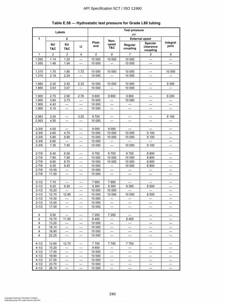
ISO 11960:2004(E)
240 © ISO 2004 – All rights reserved
Table E.58 — Hydrostatic test pressure for Grade L80 tubing
Labels Test pressure psi
2 External upset 1
NU T&C
EU T&C IJ
Plain end
Non-upset T&C
Regular coupling
Special-clearance coupling
Integral joint
1 2 3 4 5 6 7 8 9 1.050 1.14 1.20 — 10 000 10 000 10 000 — — 1.050 1.48 1.54 — 10 000 — 10 000 — —
1.315 1.70 1.80 1.72 10 000 10 000 10 000 — 10 000 1.315 2.19 2.24 — 10 000 — 10 000 — —
1.660 2.30 2.40 2.33 10 000 10 000 10 000 — 9 300 1.660 3.03 3.07 — 10 000 — 10 000 — —
1.900 2.75 2.90 2.76 9 800 9 800 9 800 — 8 200 1.900 3.65 3.73 — 10 000 — 10 000 — — 1.900 4.42 — — 10 000 — — — — 1.900 5.15 — — 10 000 — — — —
2.063 3.24 — 3.25 9 700 — — — 8 100 2.063 4.50 — — 10 000 — — — —
2-3/8 4.00 — — 9 000 9 000 — — — 2-3/8 4.60 4.70 — 10 000 10 000 10 000 9 100 — 2-3/8 5.80 5.95 — 10 000 10 000 10 000 9 100 — 2-3/8 6.60 — — 10 000 — — — — 2-3/8 7.35 7.45 — 10 000 — 10 000 9 100 —
2-7/8 6.40 6.50 — 9 700 9 700 9 700 8 800 — 2-7/8 7.80 7.90 — 10 000 10 000 10 000 8 800 — 2-7/8 8.60 8.70 — 10 000 10 000 10 000 8 800 — 2-7/8 9.35 9.45 — 10 000 — 10 000 8 800 — 2-7/8 10.50 — — 10 000 — — — — 2-7/8 11.50 — — 10 000 — — — —
3-1/2 7.70 — — 7 900 7 900 — — — 3-1/2 9.20 9.30 — 9 300 9 300 9 300 8 500 — 3-1/2 10.20 — — 10 000 10 000 — — — 3-1/2 12.70 12.95 — 10 000 10 000 10 000 8 500 — 3-1/2 14.30 — — 10 000 — — — — 3-1/2 15.50 — — 10 000 — — — — 3-1/2 17.00 — — 10 000 — — — —
4 9.50 — — 7 200 7 200 — — — 4 10.70 11.00 — 8 400 — 8 400 — — 4 13.20 — — 10 000 — — — — 4 16.10 — — 10 000 — — — — 4 18.90 — — 10 000 — — — — 4 22.20 — — 10 000 — — — —
4-1/2 12.60 12.75 — 7 700 7 700 7 700 — — 4-1/2 15.20 — — 9 600 — — — — 4-1/2 17.00 — — 10 000 — — — — 4-1/2 18.90 — — 10 000 — — — — 4-1/2 21.50 — — 10 000 — — — — 4-1/2 23.70 — — 10 000 — — — — 4-1/2 26.10 — — 10 000 — — — —
API Specification 5CT / ISO 11960
240Copyright American Petroleum Institute Reproduced by IHS under license with API
Not for ResaleNo reproduction or networking permitted without license from IHS
--`,,,```-`-`,,`,,`,`,,`---
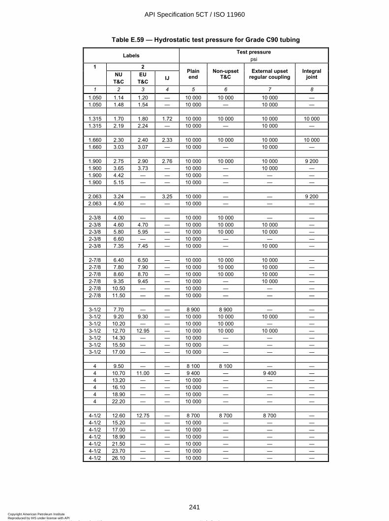
ISO 11960:2004(E)
© ISO 2004 – All rights reserved 241
Table E.59 — Hydrostatic test pressure for Grade C90 tubing
Labels Test pressure psi
2 1 NU
T&C EU
T&C IJ Plain end
Non-upset T&C
External upset regular coupling
Integral joint
1 2 3 4 5 6 7 8 1.050 1.14 1.20 — 10 000 10 000 10 000 — 1.050 1.48 1.54 — 10 000 — 10 000 —
1.315 1.70 1.80 1.72 10 000 10 000 10 000 10 000 1.315 2.19 2.24 — 10 000 — 10 000 —
1.660 2.30 2.40 2.33 10 000 10 000 10 000 10 000 1.660 3.03 3.07 — 10 000 — 10 000 —
1.900 2.75 2.90 2.76 10 000 10 000 10 000 9 200 1.900 3.65 3.73 — 10 000 — 10 000 — 1.900 4.42 — — 10 000 — — — 1.900 5.15 — — 10 000 — — —
2.063 3.24 — 3.25 10 000 — — 9 200 2.063 4.50 — — 10 000 — — —
2-3/8 4.00 — — 10 000 10 000 — — 2-3/8 4.60 4.70 — 10 000 10 000 10 000 — 2-3/8 5.80 5.95 — 10 000 10 000 10 000 — 2-3/8 6.60 — — 10 000 — — — 2-3/8 7.35 7.45 — 10 000 — 10 000 —
2-7/8 6.40 6.50 — 10 000 10 000 10 000 — 2-7/8 7.80 7.90 — 10 000 10 000 10 000 — 2-7/8 8.60 8.70 — 10 000 10 000 10 000 — 2-7/8 9.35 9.45 — 10 000 — 10 000 — 2-7/8 10.50 — — 10 000 — — — 2-7/8 11.50 — — 10 000 — — —
3-1/2 7.70 — — 8 900 8 900 — — 3-1/2 9.20 9.30 — 10 000 10 000 10 000 — 3-1/2 10.20 — — 10 000 10 000 — — 3-1/2 12.70 12.95 — 10 000 10 000 10 000 — 3-1/2 14.30 — — 10 000 — — — 3-1/2 15.50 — — 10 000 — — — 3-1/2 17.00 — — 10 000 — — —
4 9.50 — — 8 100 8 100 — — 4 10.70 11.00 — 9 400 — 9 400 — 4 13.20 — — 10 000 — — — 4 16.10 — — 10 000 — — — 4 18.90 — — 10 000 — — — 4 22.20 — — 10 000 — — —
4-1/2 12.60 12.75 — 8 700 8 700 8 700 — 4-1/2 15.20 — — 10 000 — — — 4-1/2 17.00 — — 10 000 — — — 4-1/2 18.90 — — 10 000 — — — 4-1/2 21.50 — — 10 000 — — — 4-1/2 23.70 — — 10 000 — — — 4-1/2 26.10 — — 10 000 — — —
API Specification 5CT / ISO 11960
241Copyright American Petroleum Institute Reproduced by IHS under license with API
Not for ResaleNo reproduction or networking permitted without license from IHS
--`,,,```-`-`,,`,,`,`,,`---
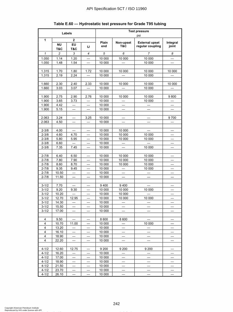
ISO 11960:2004(E)
242 © ISO 2004 – All rights reserved
Table E.60 — Hydrostatic test pressure for Grade T95 tubing
Labels Test pressure psi
2 1 NU
T&C EU
T&C IJ Plain end
Non-upset T&C
External upset regular coupling
Integral joint
1 2 3 4 5 6 7 8 1.050 1.14 1.20 — 10 000 10 000 10 000 — 1.050 1.48 1.54 — 10 000 — 10 000 —
1.315 1.70 1.80 1.72 10 000 10 000 10 000 10 000 1.315 2.19 2.24 — 10 000 — 10 000 —
1.660 2.30 2.40 2.33 10 000 10 000 10 000 10 000 1.660 3.03 3.07 — 10 000 — 10 000 —
1.900 2.75 2.90 2.76 10 000 10 000 10 000 9 800 1.900 3.65 3.73 — 10 000 — 10 000 — 1.900 4.42 — — 10 000 — — — 1.900 5.15 — — 10 000 — — —
2.063 3.24 — 3.25 10 000 — — 9 700 2.063 4.50 — — 10 000 — — —
2-3/8 4.00 — — 10 000 10 000 — — 2-3/8 4.60 4.70 — 10 000 10 000 10 000 — 2-3/8 5.80 5.95 — 10 000 10 000 10 000 — 2-3/8 6.60 — — 10 000 — — — 2-3/8 7.35 7.45 — 10 000 — 10 000 —
2-7/8 6.40 6.50 — 10 000 10 000 10 000 — 2-7/8 7.80 7.90 — 10 000 10 000 10 000 — 2-7/8 8.60 8.70 — 10 000 10 000 10 000 — 2-7/8 9.35 9.45 — 10 000 — 10 000 — 2-7/8 10.50 — — 10 000 — — — 2-7/8 11.50 — — 10 000 — — —
3-1/2 7.70 — — 9 400 9 400 — — 3-1/2 9.20 9.30 — 10 000 10 000 10 000 — 3-1/2 10.20 — — 10 000 10 000 — — 3-1/2 12.70 12.95 — 10 000 10 000 10 000 — 3-1/2 14.30 — — 10 000 — — — 3-1/2 15.50 — — 10 000 — — — 3-1/2 17.00 — — 10 000 — — —
4 9.50 — — 8 600 8 600 — — 4 10.70 11.00 — 10 000 — 10 000 — 4 13.20 — — 10 000 — — — 4 16.10 — — 10 000 — — — 4 18.90 — — 10 000 — — — 4 22.20 — — 10 000 — — —
4-1/2 12.60 12.75 — 9 200 9 200 9 200 — 4-1/2 16.20 — — 10 000 — — — 4-1/2 17.00 — — 10 000 — — — 4-1/2 18.90 — — 10 000 — — — 4-1/2 21.50 — — 10 000 — — — 4-1/2 23.70 — — 10 000 — — — 4-1/2 26.10 — — 10 000 — — —
API Specification 5CT / ISO 11960
242Copyright American Petroleum Institute Reproduced by IHS under license with API
Not for ResaleNo reproduction or networking permitted without license from IHS
--`,,,```-`-`,,`,,`,`,,`---
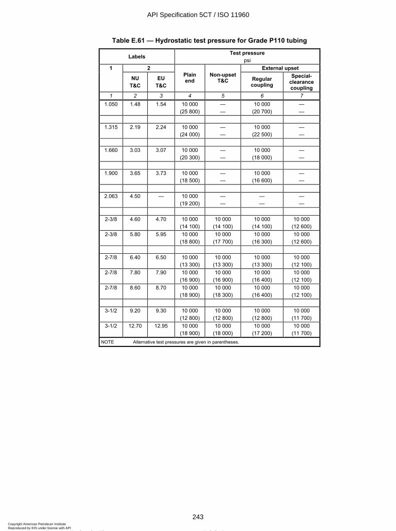
ISO 11960:2004(E)
© ISO 2004 – All rights reserved 243
Table E.61 — Hydrostatic test pressure for Grade P110 tubing
Labels Test pressure psi
1 2 External upset
NU T&C
EU T&C
Plain end
Non-upset T&C Regular
coupling Special-
clearance coupling
1 2 3 4 5 6 7 1.050 1.48 1.54 10 000
(25 800) — —
10 000 (20 700)
— —
1.315 2.19 2.24 10 000
(24 000) — —
10 000 (22 500)
— —
1.660 3.03 3.07 10 000
(20 300) — —
10 000 (18 000)
— —
1.900 3.65 3.73 10 000
(18 500) — —
10 000 (16 600)
— —
2.063 4.50 — 10 000
(19 200) — —
— —
— —
2-3/8 4.60 4.70 10 000
(14 100) 10 000
(14 100) 10 000
(14 100) 10 000
(12 600) 2-3/8 5.80 5.95 10 000
(18 800) 10 000
(17 700) 10 000
(16 300) 10 000
(12 600)
2-7/8 6.40 6.50 10 000 (13 300)
10 000 (13 300)
10 000 (13 300)
10 000 (12 100)
2-7/8 7.80 7.90 10 000 (16 900)
10 000 (16 900)
10 000 (16 400)
10 000 (12 100)
2-7/8 8.60 8.70 10 000 (18 900)
10 000 (18 300)
10 000 (16 400)
10 000 (12 100)
3-1/2 9.20 9.30 10 000
(12 800) 10 000
(12 800) 10 000
(12 800) 10 000
(11 700) 3-1/2 12.70 12.95 10 000
(18 900) 10 000
(18 000) 10 000
(17 200) 10 000
(11 700) NOTE Alternative test pressures are given in parentheses.
API Specification 5CT / ISO 11960
243Copyright American Petroleum Institute Reproduced by IHS under license with API
Not for ResaleNo reproduction or networking permitted without license from IHS
--`,,,```-`-`,,`,,`,`,,`---
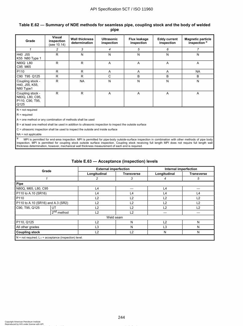
ISO 11960:2004(E)
244 © ISO 2004 – All rights reserved
Table E.62 — Summary of NDE methods for seamless pipe, coupling stock and the body of welded pipe
Grade Visual
inspection (see 10.14)
Wall thickness determination
Ultrasonic inspection
Flux leakage inspection
Eddy current inspection
Magnetic particle inspection a
1 2 3 4 5 6 7 H40 J55 K55 N80 Type 1
R N N N N N
N80Q L80 C95 M65
R R A A A A
P110 R R A A A NA C90 T95 Q125 R R C B B B Coupling stock - H40, J55, K55, N80 Type1
R NA N N N N
Coupling stock - N80Q, L80, C95, P110, C90, T95, Q125
R R A A A A
N = not required
R = required
A = one method or any combination of methods shall be used
B = at least one method shall be used in addition to ultrasonic inspection to inspect the outside surface
C = ultrasonic inspection shall be used to inspect the outside and inside surface
NA = not applicable
a MPI is permitted for end-area inspection. MPI is permitted for pipe-body outside-surface inspection in combination with other methods of pipe body inspection. MPI is permitted for coupling stock outside surface inspection. Coupling stock receiving full length MPI does not require full length wall thickness determination, however, mechanical wall thickness measurement of each end is required.
Table E.63 — Acceptance (inspection) levels
External imperfection Internal imperfection Grade Longitudinal Transverse Longitudinal Transverse
1 2 3 4 5 Pipe N80Q, M65, L80, C95 L4 — L4 — P110 to A.10 (SR16) L4 L4 L4 L4 P110 L2 L2 L2 L2 P110 to A.10 (SR16) and A.3 (SR2) L2 L2 L2 L2
UT L2 L2 L2 L2 C90, T95, Q125 2nd method L2 L2 — —
Weld seam P110, Q125 L2 N L2 N All other grades L3 N L3 N Coupling stock L2 L2 N N N = not required; L x = acceptance (inspection) level.
API Specification 5CT / ISO 11960
244Copyright American Petroleum Institute Reproduced by IHS under license with API
Not for ResaleNo reproduction or networking permitted without license from IHS
--`,,,```-`-`,,`,,`,`,,`---
ISO 11960:2004(E)
© ISO 2004 – All rights reserved 245
Table E.64 — Artificial reference indicators
Acceptance (inspection) level
Notch depth a max.
%
Notch length max. at full depth
in
Width max.
in
Radially drilled hole diameter b
in 1 2 3 4 5
L2 5 2.0 0.040 1/16 L3 10 2.0 0.040 1/8 L4 12.5 2.0 0.040 1/8
NOTE See Figure D.17. a Depth as a percent of specified wall thickness. The depth tolerance shall be ± 15 % of the calculated notch depth, with a minimum notch depth of 0.012 in ± 0.002 in. b Drilled hole diameter (through the pipe wall) shall be based on the drill bit size.
Table E.65 — Size of stamp markings
Product Label 1 Marking height in
Pipe < 4-1/2 W 4-1/2
3/16 ¼
Coupling For pipe sizes < 4-1/2 For pipe sizes W 4-1/2 to < 7-5/8
For pipe sizes W 7-5/8
¼ 3/8 ½
API Specification 5CT / ISO 11960
245Copyright American Petroleum Institute Reproduced by IHS under license with API
Not for ResaleNo reproduction or networking permitted without license from IHS
--`,,,```-`-`,,`,,`,`,,`---
ISO 11960:2004(E)
246 © ISO 2004 – All rights reserved
Table E.66 — Grade colour codes
Colour(s) for coupling Grade Grade type
Number and colour of bands for pipe, coupling stock and pup joints of length WWWW 6.0 ft Entire coupling Band(s) a
1 2 3 4 5 H40 None or black band at the manufacturer’s option None Same as for pipe J55
tubing One bright green Bright green None
J55 casing
One bright green Bright green One white
K55 Two bright green Bright green None M65 One bright green, one blue M65 pipe uses L80 Type 1 couplings N80 1 One red Red None N80 Q One red, one bright green Red Green L80 1 One red, one brown Red One brown L80 9Cr One red, one brown, two yellow Red Two yellow L80 13Cr One red, one brown, one yellow Red One yellow C90 1 One purple Purple None C90 2 One purple, one yellow Purple One yellow T95 1 One silver Silver None T95 2 One silver, one yellow Silver One yellow C95 One brown Brown None P110 One white White None Q125 1 One orange Orange None Q125 2 One orange, one yellow Orange One yellow Q125 3 One orange, one green Orange One green Q125 4 One orange, one brown Orange One brown
a Special-clearance couplings shall also have a black band.
Table E.67 — Thread type markings
Product Thread type Marked symbol Casing Short round
Long round Buttress
Extreme-line
STC LC BC XC
Tubing Non-upset External upset Integral joint
NU EU IJ
API Specification 5CT / ISO 11960
246Copyright American Petroleum Institute Reproduced by IHS under license with API
Not for ResaleNo reproduction or networking permitted without license from IHS
--`,,,```-`-`,,`,,`,`,,`---
ISO 11960:2004(E)
© ISO 2004 – All rights reserved 247
Table E.68 — Marking requirements and sequence
Stencil and/or stamp marking requirements a
Groups 1 and 3 Groups 2 and 4 All groups Marking sequence Mark or
symbol b Pipe and pup-joints
Couplings and
accessoriesPipe and
pup-joints Couplings
and accessories
Coupling stock
1 2 3 4 5 6 7 8 1 Manufacturer’s name or mark « ... » D or P D or P P P P 2 ISO 11960
Marking to indicate API 5CT is at manufacturer's option or as specified on purchase agreement. Date of manufacture as in 11.1.8 or 11.1.9.
ISO 11960
5CT c
« ... »
D or P
D or P
D or P
D or P
D or P
D or P
P
P
P
P
P
P
P
P
P 3 Unthreaded pipe or special end finish, if
applicable (place symbol after specification marking): — Unthreaded pipe either upset or non-
upset — Pipe with special end finish threaded by
the pipe mill or processor — Completed couplings or completed
accessories threaded with special end finish
— Coupling stock identification
UF
SF
SF CS
D or P
D or P
D or P
P
P
P P
4 Size designation (fill in Label 1 designation from column 1 of Table E.1, E.2 or E.3) Specified diameter for coupling stock
« ... »
P
P
P 5 Mass designation
(fill in Label 2 designation from column 2 of Table E.1, E.2 or E.3) Specified wall thickness for coupling stock
« ..... »
D or P
P
P 6 Grade of pipe:
— H40 — J55 — K55 — N80 Type 1 — N80Q — M65 — L80 — P110 — C95 — L80 Type 9Cr — L80 Type 13Cr — C90 Type 1 — C90 Type 2 — T95 Type 1 — T95 Type 2 — Q125 Type 1 — Q125 Type 2 — Q125 Type 3 — Q125 Type 4 All grade designations
H J K
N1 NQ M L P C L9
L13 C90-1 C90-2 T95-1 T95-2
Q1 Q2 Q3 Q4
D or P D or P P P P 7 Reduced alternative impact test temperature,
if applicable. Fill in specified test temperature for full-size specimens, including ± symbol and °F
« ... »F P P P P
8 Heat treatment, if applicable: — J55, K55 or M65 normalized — J55, K55 or M65 quenched & tempered
Z Q
P P
P P
P P
P P
P P
API Specification 5CT / ISO 11960
247Copyright American Petroleum Institute Reproduced by IHS under license with API
Not for ResaleNo reproduction or networking permitted without license from IHS
--`,,,```-`-`,,`,,`,`,,`---
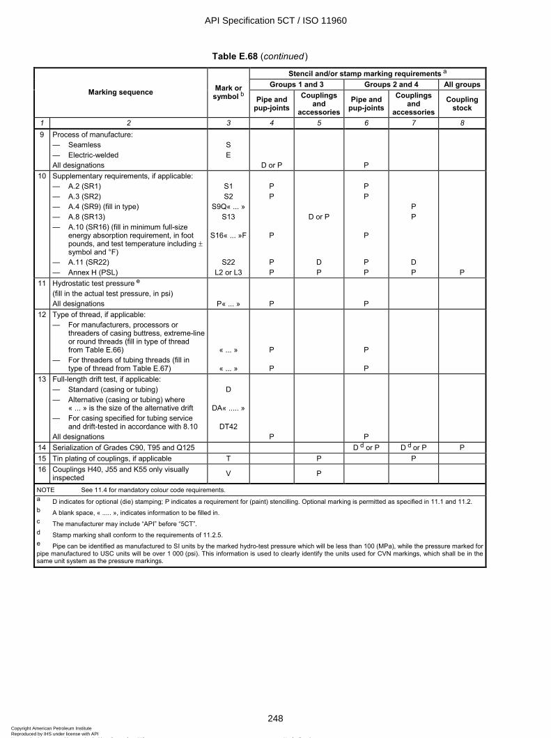
ISO 11960:2004(E)
248 © ISO 2004 – All rights reserved
Table E.68 (continued)
Stencil and/or stamp marking requirements a
Groups 1 and 3 Groups 2 and 4 All groups Marking sequence Mark or
symbol b Pipe and pup-joints
Couplings and
accessoriesPipe and
pup-joints Couplings
and accessories
Coupling stock
1 2 3 4 5 6 7 8 9 Process of manufacture:
— Seamless — Electric-welded All designations
S E
D or P
P
10 Supplementary requirements, if applicable: — A.2 (SR1) — A.3 (SR2) — A.4 (SR9) (fill in type) — A.8 (SR13) — A.10 (SR16) (fill in minimum full-size
energy absorption requirement, in foot pounds, and test temperature including ± symbol and °F)
— A.11 (SR22) — Annex H (PSL)
S1 S2
S9Q« ... » S13
S16« ... »F
S22 L2 or L3
P P
P
P P
D or P
D P
P P
P
P P
P P
D P P
11 Hydrostatic test pressure e (fill in the actual test pressure, in psi) All designations P« ... » P
P
12 Type of thread, if applicable: — For manufacturers, processors or
threaders of casing buttress, extreme-line or round threads (fill in type of thread from Table E.66)
— For threaders of tubing threads (fill in type of thread from Table E.67)
« ... »
« ... »
P
P
P
P
13 Full-length drift test, if applicable: — Standard (casing or tubing) — Alternative (casing or tubing) where
« ... » is the size of the alternative drift — For casing specified for tubing service
and drift-tested in accordance with 8.10 All designations
D
DA« ..... »
DT42 P
P
14 Serialization of Grades C90, T95 and Q125 D d or P D d or P P 15 Tin plating of couplings, if applicable T P P 16 Couplings H40, J55 and K55 only visually
inspected V P
NOTE See 11.4 for mandatory colour code requirements. a D indicates for optional (die) stamping; P indicates a requirement for (paint) stencilling. Optional marking is permitted as specified in 11.1 and 11.2. b A blank space, « ..... », indicates information to be filled in. c The manufacturer may include “API” before “5CT”. d Stamp marking shall conform to the requirements of 11.2.5. e Pipe can be identified as manufactured to SI units by the marked hydro-test pressure which will be less than 100 (MPa), while the pressure marked for pipe manufactured to USC units will be over 1 000 (psi). This information is used to clearly identify the units used for CVN markings, which shall be in the same unit system as the pressure markings.
API Specification 5CT / ISO 11960
248Copyright American Petroleum Institute Reproduced by IHS under license with API
Not for ResaleNo reproduction or networking permitted without license from IHS
--`,,,```-`-`,,`,,`,`,,`---
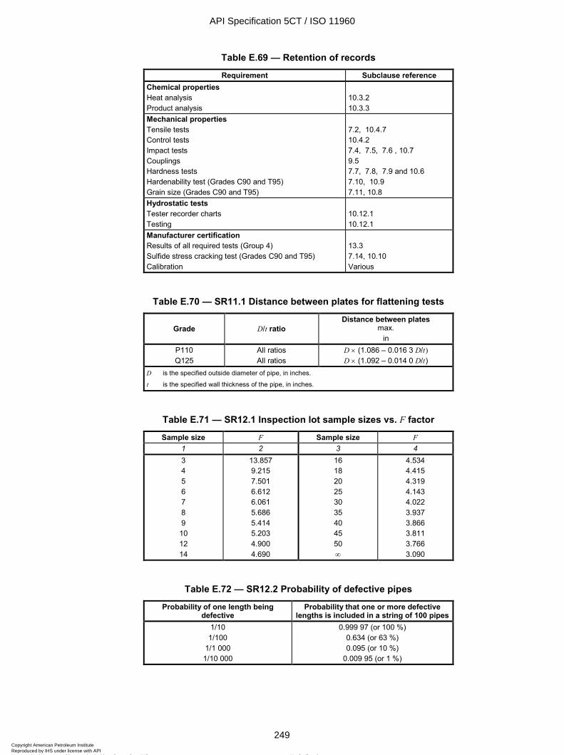
ISO 11960:2004(E)
© ISO 2004 – All rights reserved 249
Table E.69 — Retention of records
Requirement Subclause reference Chemical properties Heat analysis Product analysis
10.3.2 10.3.3
Mechanical properties Tensile tests Control tests Impact tests Couplings Hardness tests Hardenability test (Grades C90 and T95) Grain size (Grades C90 and T95)
7.2, 10.4.7 10.4.2 7.4, 7.5, 7.6 , 10.7 9.5 7.7, 7.8, 7.9 and 10.6 7.10, 10.9 7.11, 10.8
Hydrostatic tests Tester recorder charts Testing
10.12.1 10.12.1
Manufacturer certification Results of all required tests (Group 4) Sulfide stress cracking test (Grades C90 and T95) Calibration
13.3 7.14, 10.10 Various
Table E.70 — SR11.1 Distance between plates for flattening tests
Grade D/t ratio Distance between plates
max. in
P110 Q125
All ratios All ratios
D × (1.086 – 0.016 3 D/t) D × (1.092 – 0.014 0 D/t)
D is the specified outside diameter of pipe, in inches.
t is the specified wall thickness of the pipe, in inches.
Table E.71 — SR12.1 Inspection lot sample sizes vs. F factor
Sample size F Sample size F 1 2 3 4 3 4 5 6 7 8 9 10 12 14
13.857 9.215 7.501 6.612 6.061 5.686 5.414 5.203 4.900 4.690
16 18 20 25 30 35 40 45 50 ∞
4.534 4.415 4.319 4.143 4.022 3.937 3.866 3.811 3.766 3.090
Table E.72 — SR12.2 Probability of defective pipes
Probability of one length being defective
Probability that one or more defective lengths is included in a string of 100 pipes
1/10 1/100
1/1 000 1/10 000
0.999 97 (or 100 %) 0.634 (or 63 %) 0.095 (or 10 %)
0.009 95 (or 1 %)
API Specification 5CT / ISO 11960
249Copyright American Petroleum Institute Reproduced by IHS under license with API
Not for ResaleNo reproduction or networking permitted without license from IHS
--`,,,```-`-`,,`,,`,`,,`---
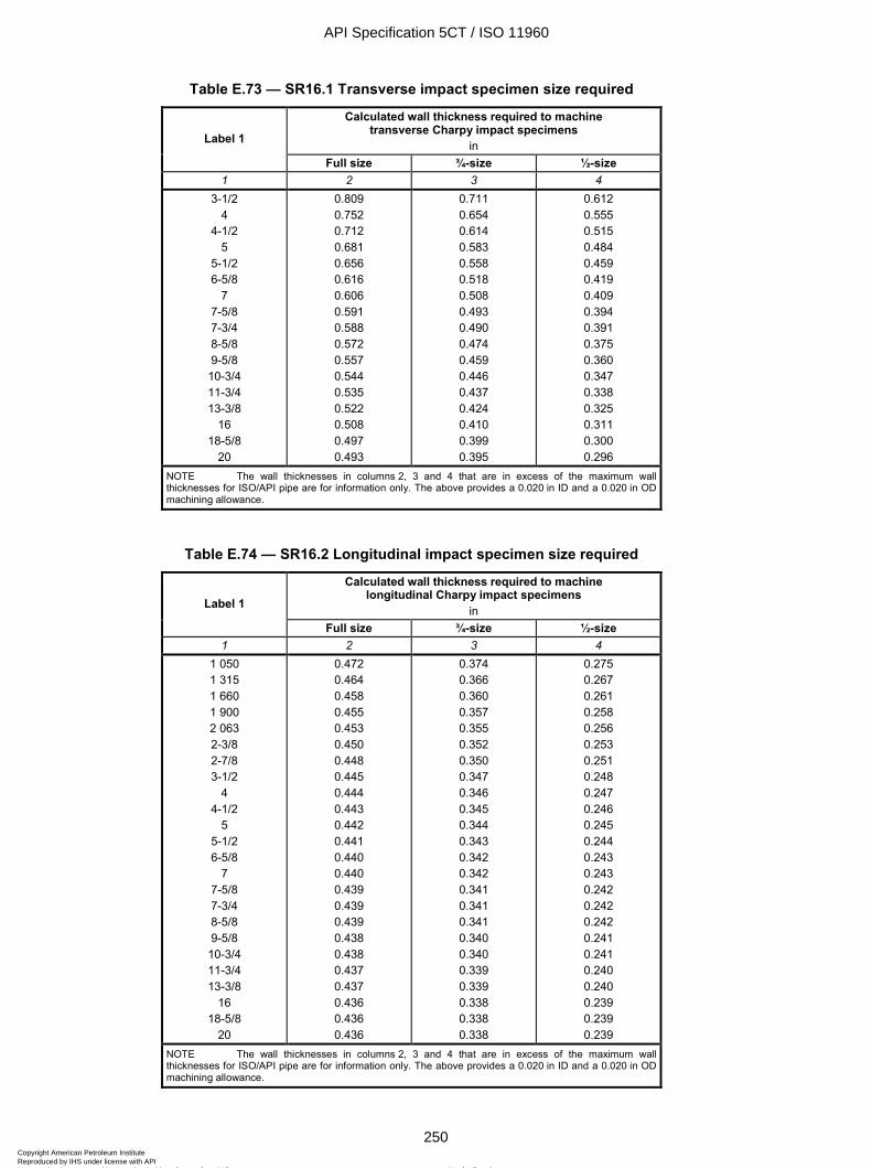
ISO 11960:2004(E)
250 © ISO 2004 – All rights reserved
Table E.73 — SR16.1 Transverse impact specimen size required
Calculated wall thickness required to machine transverse Charpy impact specimens
in Label 1
Full size ¾-size ½-size 1 2 3 4
3-1/2 4
4-1/2 5
5-1/2 6-5/8
7 7-5/8 7-3/4 8-5/8 9-5/8 10-3/4 11-3/4 13-3/8
16 18-5/8
20
0.809 0.752 0.712 0.681 0.656 0.616 0.606 0.591 0.588 0.572 0.557 0.544 0.535 0.522 0.508 0.497 0.493
0.711 0.654 0.614 0.583 0.558 0.518 0.508 0.493 0.490 0.474 0.459 0.446 0.437 0.424 0.410 0.399 0.395
0.612 0.555 0.515 0.484 0.459 0.419 0.409 0.394 0.391 0.375 0.360 0.347 0.338 0.325 0.311 0.300 0.296
NOTE The wall thicknesses in columns 2, 3 and 4 that are in excess of the maximum wall thicknesses for ISO/API pipe are for information only. The above provides a 0.020 in ID and a 0.020 in OD machining allowance.
Table E.74 — SR16.2 Longitudinal impact specimen size required
Calculated wall thickness required to machine longitudinal Charpy impact specimens
in Label 1
Full size ¾-size ½-size 1 2 3 4
1 050 1 315 1 660 1 900 2 063 2-3/8 2-7/8 3-1/2
4 4-1/2
5 5-1/2 6-5/8
7 7-5/8 7-3/4 8-5/8 9-5/8 10-3/4 11-3/4 13-3/8
16 18-5/8
20
0.472 0.464 0.458 0.455 0.453 0.450 0.448 0.445 0.444 0.443 0.442 0.441 0.440 0.440 0.439 0.439 0.439 0.438 0.438 0.437 0.437 0.436 0.436 0.436
0.374 0.366 0.360 0.357 0.355 0.352 0.350 0.347 0.346 0.345 0.344 0.343 0.342 0.342 0.341 0.341 0.341 0.340 0.340 0.339 0.339 0.338 0.338 0.338
0.275 0.267 0.261 0.258 0.256 0.253 0.251 0.248 0.247 0.246 0.245 0.244 0.243 0.243 0.242 0.242 0.242 0.241 0.241 0.240 0.240 0.239 0.239 0.239
NOTE The wall thicknesses in columns 2, 3 and 4 that are in excess of the maximum wall thicknesses for ISO/API pipe are for information only. The above provides a 0.020 in ID and a 0.020 in OD machining allowance.
API Specification 5CT / ISO 11960
250Copyright American Petroleum Institute Reproduced by IHS under license with API
Not for ResaleNo reproduction or networking permitted without license from IHS
--`,,,```-`-`,,`,,`,`,,`---
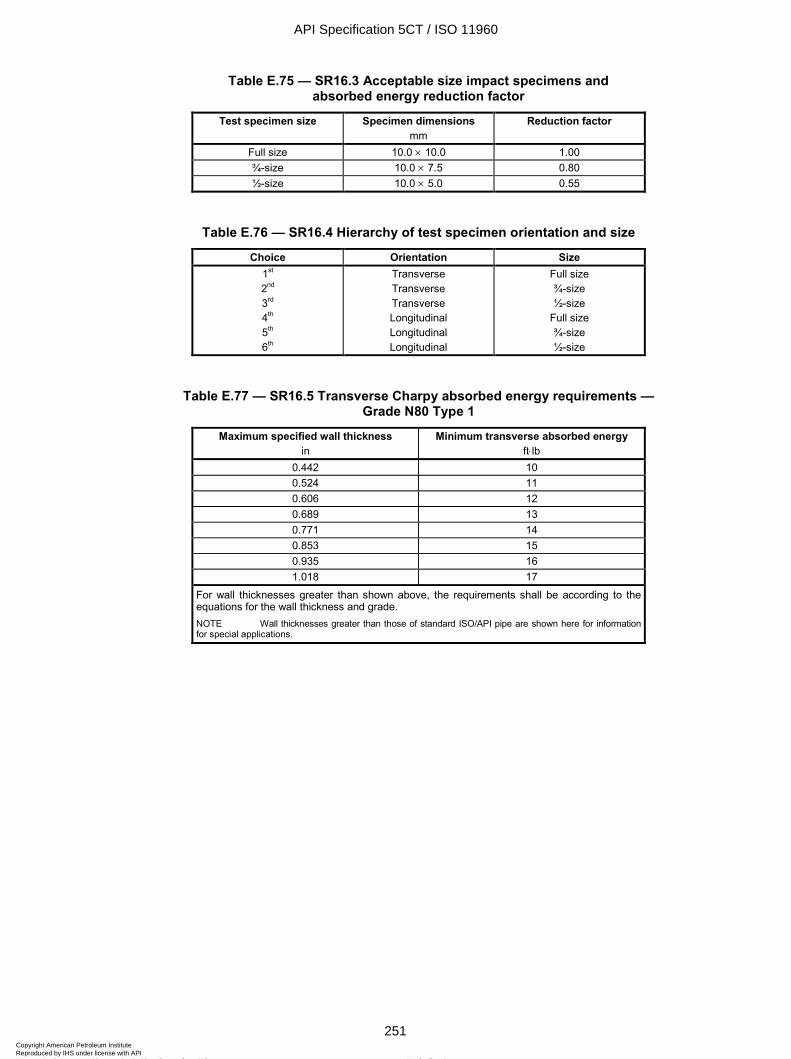
ISO 11960:2004(E)
© ISO 2004 – All rights reserved 251
Table E.75 — SR16.3 Acceptable size impact specimens and absorbed energy reduction factor
Test specimen size Specimen dimensions mm
Reduction factor
Full size 10.0 × 10.0 1.00 ¾-size 10.0 × 7.5 0.80 ½-size 10.0 × 5.0 0.55
Table E.76 — SR16.4 Hierarchy of test specimen orientation and size
Choice Orientation Size 1st 2nd 3rd 4th 5th 6th
Transverse Transverse Transverse Longitudinal Longitudinal Longitudinal
Full size ¾-size ½-size
Full size ¾-size ½-size
Table E.77 — SR16.5 Transverse Charpy absorbed energy requirements — Grade N80 Type 1
Maximum specified wall thickness in
Minimum transverse absorbed energy ft⋅lb
0.442 10 0.524 11 0.606 12 0.689 13 0.771 14 0.853 15 0.935 16 1.018 17
For wall thicknesses greater than shown above, the requirements shall be according to the equations for the wall thickness and grade. NOTE Wall thicknesses greater than those of standard ISO/API pipe are shown here for information for special applications.
API Specification 5CT / ISO 11960
251Copyright American Petroleum Institute Reproduced by IHS under license with API
Not for ResaleNo reproduction or networking permitted without license from IHS
--`,,,```-`-`,,`,,`,`,,`---

ISO 11960:2004(E)
252 © ISO 2004 – All rights reserved
Table E.78 — SR16.6 Longitudinal Charpy absorbed energy requirements — Grade N80 Type 1
Maximum specified wall thickness in
Minimum longitudinal absorbed energy ft⋅lb
0.421 20 0.462 21 0.504 22 0.545 23 0.586 24 0.627 25 0.668 26 0.709 27 0.750 28 0.791 29 0.833 30 0.874 31 0.915 32 0.956 33 0.997 34 1.038 35
For wall thicknesses greater than shown above, the requirements shall be according to the equations for the wall thickness and grade. NOTE Wall thicknesses greater than those of standard ISO/API pipe are shown here for information for special applications.
Table E.79 — SR16.7 Test temperature reduction for sub-size specimens — Grades H40, J55 and K55 only
Specimen size Specified pipe wall thickness Temperature reduction
mm in ∞F 10.0 × 7.5 > 0.394 5 10.0 × 5.0 > 0.394 20 10.0 × 5.0 0.295 to 0.394 15 10.0 × 5.0 0.264 to 0.291 10 10.0 × 5.0 0.236 to 0.260 5
API Specification 5CT / ISO 11960
252Copyright American Petroleum Institute Reproduced by IHS under license with API
Not for ResaleNo reproduction or networking permitted without license from IHS
--`,,,```-`-`,,`,,`,`,,`---
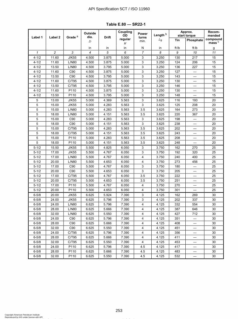
ISO 11960:2004(E)
© ISO 2004 – All rights reserved 253
Table E.80 — SR22-1
Approx. start torque Label 1 Label 2 Grade a
Outside dia.
D Drift
Coupling OD
regular W
Power turns min.
Length b L9 Tin Phosphate
Recom-mended
compound mass c
in in in N in ft⋅lb ft⋅lb g 1 2 3 4 5 6 7 8 9 10 11
4-1/2 11.60 J/K55 4.500 3.875 5.000 3 3.250 130 217 15 4-1/2 11.60 L/N80 4.500 3.875 5.000 3 3.250 124 206 15 4-1/2 13.50 L/N80 4.500 3.795 5.000 3 3.250 136 227 15 4-1/2 11.60 C90 4.500 3.875 5.000 3 3.250 127 — 15 4-1/2 13.50 C90 4.500 3.795 5.000 3 3.250 143 — 15 4-1/2 11.60 C/T95 4.500 3.875 5.000 3 3.250 130 — 15 4-1/2 13.50 C/T95 4.500 3.795 5.000 3 3.250 146 — 15 4-1/2 11.60 P110 4.500 3.875 5.000 3 3.250 130 — 15 4-1/2 13.50 P110 4.500 3.795 5.000 3 3.250 148 — 15
5 13.00 J/K55 5.000 4.369 5.563 3 3.625 116 193 20 5 15.00 J/K55 5.000 4.283 5.563 3 3.625 125 208 20 5 15.00 L/N80 5.000 4.283 5.563 3.5 3.625 164 273 20 5 18.00 L/N80 5.000 4.151 5.563 3.5 3.625 220 367 20 5 15.00 C90 5.000 4.283 5.563 3 3.625 198 — 20 5 18.00 C90 5.000 4.151 5.563 3 3.625 238 — 20 5 15.00 C/T95 5.000 4.283 5.563 3.5 3.625 202 — 20 5 18.00 C/T95 5.000 4.151 5.563 3.5 3.625 243 — 20 5 15.00 P110 5.000 4.283 5.563 3.5 3.625 208 — 20 5 18.00 P110 5.000 4.151 5.563 3.5 3.625 248 — 20
5-1/2 15.50 J/K55 5.500 4.825 6.050 3 3.750 162 270 25 5-1/2 17.00 J/K55 5.500 4.767 6.050 3 3.750 192 320 25 5-1/2 17.00 L/N80 5.500 4.767 6.050 4 3.750 240 400 25 5-1/2 20.00 L/N80 5.500 4.653 6.050 4 3.750 273 456 25 5-1/2 17.00 C90 5.500 4.767 6.050 3 3.750 180 — 25 5-1/2 20.00 C90 5.500 4.653 6.050 3 3.750 205 — 25 5-1/2 17.00 C/T95 5.500 4.767 6.050 3.5 3.750 222 — 25 5-1/2 20.00 C/T95 5.500 4.653 6.050 3.5 3.750 251 — 25 5-1/2 17.00 P110 5.500 4.767 6.050 4 3.750 270 — 25 5-1/2 20.00 P110 5.500 4.653 6.050 4 3.750 301 — 25 6-5/8 20.00 J/K55 6.625 5.924 7.390 3 4.125 162 269 30 6-5/8 24.00 J/K55 6.625 5.796 7.390 3 4.125 202 337 30 6-5/8 24.00 L/N80 6.625 5.796 7.390 4 4.125 332 554 30 6-5/8 28.00 L/N80 6.625 5.666 7.390 4 4.125 387 646 30 6-5/8 32.00 L/N80 6.625 5.550 7.390 4 4.125 427 712 30 6-5/8 24.00 C90 6.625 5.796 7.390 4 4.125 351 — 30 6-5/8 28.00 C90 6.625 5.666 7.390 4 4.125 408 — 30 6-5/8 32.00 C90 6.625 5.550 7.390 4 4.125 451 — 30 6-5/8 24.00 C/T95 6.625 5.796 7.390 4 4.125 356 — 30 6-5/8 28.00 C/T95 6.625 5.666 7.390 4 4.125 411 — 30 6-5/8 32.00 C/T95 6.625 5.550 7.390 4 4.125 453 — 30 6-5/8 24.00 P110 6.625 5.796 7.390 4.5 4.125 417 — 30 6-5/8 28.00 P110 6.625 5.666 7.390 4.5 4.125 483 — 30 6-5/8 32.00 P110 6.625 5.550 7.390 4.5 4.125 532 — 30
API Specification 5CT / ISO 11960
253Copyright American Petroleum Institute Reproduced by IHS under license with API
Not for ResaleNo reproduction or networking permitted without license from IHS
--`,,,```-`-`,,`,,`,`,,`---
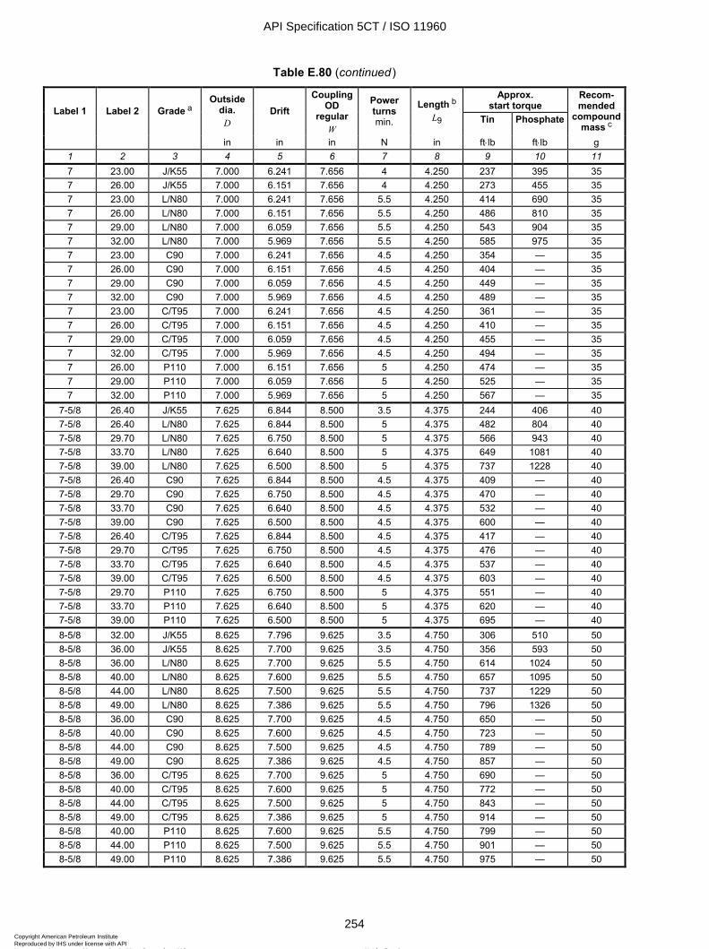
ISO 11960:2004(E)
254 © ISO 2004 – All rights reserved
Table E.80 (continued)
Approx. start torque Label 1 Label 2 Grade a
Outside dia.
D Drift
Coupling OD
regular W
Power turns min.
Length b L9 Tin Phosphate
Recom-mended
compound mass c
in in in N in ft⋅lb ft⋅lb g 1 2 3 4 5 6 7 8 9 10 11 7 23.00 J/K55 7.000 6.241 7.656 4 4.250 237 395 35 7 26.00 J/K55 7.000 6.151 7.656 4 4.250 273 455 35 7 23.00 L/N80 7.000 6.241 7.656 5.5 4.250 414 690 35 7 26.00 L/N80 7.000 6.151 7.656 5.5 4.250 486 810 35 7 29.00 L/N80 7.000 6.059 7.656 5.5 4.250 543 904 35 7 32.00 L/N80 7.000 5.969 7.656 5.5 4.250 585 975 35 7 23.00 C90 7.000 6.241 7.656 4.5 4.250 354 — 35 7 26.00 C90 7.000 6.151 7.656 4.5 4.250 404 — 35 7 29.00 C90 7.000 6.059 7.656 4.5 4.250 449 — 35 7 32.00 C90 7.000 5.969 7.656 4.5 4.250 489 — 35 7 23.00 C/T95 7.000 6.241 7.656 4.5 4.250 361 — 35 7 26.00 C/T95 7.000 6.151 7.656 4.5 4.250 410 — 35 7 29.00 C/T95 7.000 6.059 7.656 4.5 4.250 455 — 35 7 32.00 C/T95 7.000 5.969 7.656 4.5 4.250 494 — 35 7 26.00 P110 7.000 6.151 7.656 5 4.250 474 — 35 7 29.00 P110 7.000 6.059 7.656 5 4.250 525 — 35 7 32.00 P110 7.000 5.969 7.656 5 4.250 567 — 35
7-5/8 26.40 J/K55 7.625 6.844 8.500 3.5 4.375 244 406 40 7-5/8 26.40 L/N80 7.625 6.844 8.500 5 4.375 482 804 40 7-5/8 29.70 L/N80 7.625 6.750 8.500 5 4.375 566 943 40 7-5/8 33.70 L/N80 7.625 6.640 8.500 5 4.375 649 1081 40 7-5/8 39.00 L/N80 7.625 6.500 8.500 5 4.375 737 1228 40 7-5/8 26.40 C90 7.625 6.844 8.500 4.5 4.375 409 — 40 7-5/8 29.70 C90 7.625 6.750 8.500 4.5 4.375 470 — 40 7-5/8 33.70 C90 7.625 6.640 8.500 4.5 4.375 532 — 40 7-5/8 39.00 C90 7.625 6.500 8.500 4.5 4.375 600 — 40 7-5/8 26.40 C/T95 7.625 6.844 8.500 4.5 4.375 417 — 40 7-5/8 29.70 C/T95 7.625 6.750 8.500 4.5 4.375 476 — 40 7-5/8 33.70 C/T95 7.625 6.640 8.500 4.5 4.375 537 — 40 7-5/8 39.00 C/T95 7.625 6.500 8.500 4.5 4.375 603 — 40 7-5/8 29.70 P110 7.625 6.750 8.500 5 4.375 551 — 40 7-5/8 33.70 P110 7.625 6.640 8.500 5 4.375 620 — 40 7-5/8 39.00 P110 7.625 6.500 8.500 5 4.375 695 — 40 8-5/8 32.00 J/K55 8.625 7.796 9.625 3.5 4.750 306 510 50 8-5/8 36.00 J/K55 8.625 7.700 9.625 3.5 4.750 356 593 50 8-5/8 36.00 L/N80 8.625 7.700 9.625 5.5 4.750 614 1024 50 8-5/8 40.00 L/N80 8.625 7.600 9.625 5.5 4.750 657 1095 50 8-5/8 44.00 L/N80 8.625 7.500 9.625 5.5 4.750 737 1229 50 8-5/8 49.00 L/N80 8.625 7.386 9.625 5.5 4.750 796 1326 50 8-5/8 36.00 C90 8.625 7.700 9.625 4.5 4.750 650 — 50 8-5/8 40.00 C90 8.625 7.600 9.625 4.5 4.750 723 — 50 8-5/8 44.00 C90 8.625 7.500 9.625 4.5 4.750 789 — 50 8-5/8 49.00 C90 8.625 7.386 9.625 4.5 4.750 857 — 50 8-5/8 36.00 C/T95 8.625 7.700 9.625 5 4.750 690 — 50 8-5/8 40.00 C/T95 8.625 7.600 9.625 5 4.750 772 — 50 8-5/8 44.00 C/T95 8.625 7.500 9.625 5 4.750 843 — 50 8-5/8 49.00 C/T95 8.625 7.386 9.625 5 4.750 914 — 50 8-5/8 40.00 P110 8.625 7.600 9.625 5.5 4.750 799 — 50 8-5/8 44.00 P110 8.625 7.500 9.625 5.5 4.750 901 — 50 8-5/8 49.00 P110 8.625 7.386 9.625 5.5 4.750 975 — 50
API Specification 5CT / ISO 11960
254Copyright American Petroleum Institute Reproduced by IHS under license with API
Not for ResaleNo reproduction or networking permitted without license from IHS
--`,,,```-`-`,,`,,`,`,,`---

ISO 11960:2004(E)
© ISO 2004 – All rights reserved 255
Table E.80 (continued)
Approx. start torque Label 1 Label 2 Grade a
Outside dia.
D Drift
Coupling OD
regular W
Power turns min.
Length b L9 Tin Phosphate
Recom-mended
compound mass c
in in in N in ft⋅lb ft⋅lb g 1 2 3 4 5 6 7 8 9 10 11
9-5/8 36.00 J/K55 9.625 8.765 10.625 3.5 5.000 393 507 55 9-5/8 40.00 J/K55 9.625 8.679 10.625 3.5 5.000 439 572 55 9-5/8 40.00 L/N80 9.625 8.679 10.625 5.5 5.000 673 1121 55 9-5/8 43.50 L/N80 9.625 8.599 10.625 5.5 5.000 767 1278 55 9-5/8 47.00 L/N80 9.625 8.525 10.625 5.5 5.000 823 1371 55 9-5/8 53.50 L/N80 9.625 8.500 d 10.625 5.5 5.000 923 1539 55 9-5/8 40.00 C90 9.625 8.679 10.625 5 5.000 675 — 55 9-5/8 43.50 C90 9.625 8.599 10.625 5 5.000 737 — 55 9-5/8 47.00 C90 9.625 8.525 10.625 5 5.000 790 — 55 9-5/8 53.50 C90 9.625 8.500 d 10.625 5 5.000 988 — 55 9-5/8 40.00 C/T95 9.625 8.679 10.625 5.5 5.000 762 — 55 9-5/8 43.50 C/T95 9.625 8.599 10.625 5.5 5.000 833 — 55 9-5/8 47.00 C/T95 9.625 8.525 10.625 5.5 5.000 893 — 55 9-5/8 53.50 C/T95 9.625 8.500 d 10.625 5.5 5.000 972 — 55 9-5/8 43.50 P110 9.625 8.599 10.625 6 5.000 914 — 55 9-5/8 47.00 P110 9.625 8.525 10.625 6 5.000 978 — 55 9-5/8 53.50 P110 9.625 8.500 d 10.625 6 5.000 1092 — 55
a L/N80 implies L80 Type 1, N80 Type 1 and N80Q. b End of pipe to apex of triangle. c The recommended mass of thread compound shown in this table is for a compound containing metals, including lead (i.e. former API Bull 5A2) which has a specific gravity of approximately 2. Use of compounds such as ISO 13678 requires less mass to achieve an equivalent volume of thread compound. Use of excessive thread compound may be detrimental to leak resistance.
NOTE For the purposes of this provision, API RP 5A3 is equivalent to ISO 13678. d The alternative size drift (see Table E.32) is shown.
API Specification 5CT / ISO 11960
255Copyright American Petroleum Institute Reproduced by IHS under license with API
Not for ResaleNo reproduction or networking permitted without license from IHS
--`,,,```-`-`,,`,,`,`,,`---
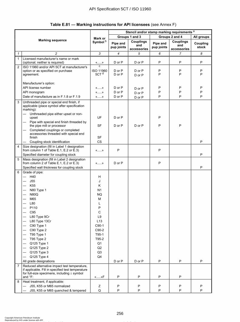
ISO 11960:2004(E)
256 © ISO 2004 – All rights reserved
Table E.81 — Marking instructions for API licensees (see Annex F)
Stencil and/or stamp marking requirements a Groups 1 and 3 Groups 2 and 4 All groups
Marking sequence Mark or Symbol b Pipe and
pup joints Couplings
and accessories
Pipe and pup joints
Couplings and
accessories Coupling
stock
1 2 3 4 5 6 7 8 1 Licensed manufacturer’s name or mark
(optional; neither is required) «.....» D or P D or P P P P 2 ISO 11960 and/or API 5CT at manufacturer's
option or as specified on purchase agreement. Manufacturer’s option: API license number API monogram Date of manufacture as in F.1.8 or F.1.9
c ISO 11960
5CT d
«.....» «.....» «.....»
D or P D or P
D or P D or P D or P
D or P D or P
D or P D or P D or P
P P
P P P
P P
P P P
P P
P P P
3 Unthreaded pipe or special end finish, if applicable (place symbol after specification marking): — Unthreaded pipe either upset or non-
upset — Pipe with special end finish threaded by
the pipe mill or processor — Completed couplings or completed
accessories threaded with special end finish
— Coupling stock identification
UF
SF
SF CS
D or P
D or P
D or P
P
P
P
P 4 Size designation (fill in Label 1 designation
from column 1 of Table E.1, E.2 or E.3) Specified diameter for coupling stock
«.....»
P
P
P 5 Mass designation (fill in Label 2 designation
from column 2 of Table E.1, E.2 or E.3) Specified wall thickness for coupling stock
«.....»
D or P
P
P 6 Grade of pipe:
— H40 — J55 — K55 — N80 Type 1 — N80Q — M65 — L80 — P110 — C95 — L80 Type 9Cr — L80 Type 13Cr — C90 Type 1 — C90 Type 2 — T95 Type 1 — T95 Type 2 — Q125 Type 1 — Q125 Type 2 — Q125 Type 3 — Q125 Type 4 All grade designations
H J K
N1 NQ M L P C L9
L13 C90-1 C90-2 T95-1 T95-2
Q1 Q2 Q3 Q4
D or P D or P P P P 7 Reduced alternative impact test temperature,
if applicable. Fill in specified test temperature for full-size specimens, including ± symbol and °F: «.....»F P P P P
8 Heat treatment, if applicable: — J55, K55 or M65 normalized — J55, K55 or M65 quenched & tempered
Z Q
P P
P P
P P
P P
P P
API Specification 5CT / ISO 11960
256Copyright American Petroleum Institute Reproduced by IHS under license with API
Not for ResaleNo reproduction or networking permitted without license from IHS
--`,,,```-`-`,,`,,`,`,,`---
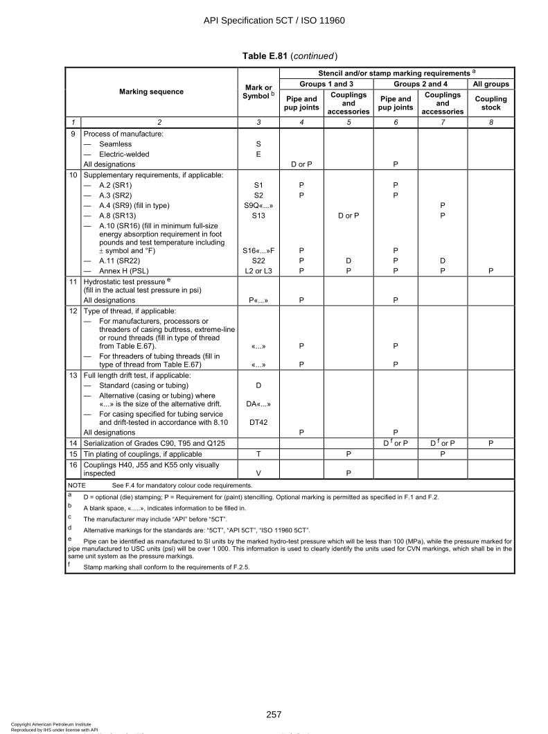
ISO 11960:2004(E)
© ISO 2004 – All rights reserved 257
Table E.81 (continued)
Stencil and/or stamp marking requirements a Groups 1 and 3 Groups 2 and 4 All groups
Marking sequence Mark or Symbol b Pipe and
pup joints Couplings
and accessories
Pipe and pup joints
Couplings and
accessoriesCoupling
stock
1 2 3 4 5 6 7 8 9 Process of manufacture:
— Seamless — Electric-welded All designations
S E
D or P
P
10 Supplementary requirements, if applicable: — A.2 (SR1) — A.3 (SR2) — A.4 (SR9) (fill in type) — A.8 (SR13) — A.10 (SR16) (fill in minimum full-size
energy absorption requirement in foot pounds and test temperature including ± symbol and °F)
— A.11 (SR22) — Annex H (PSL)
S1 S2
S9Q«...» S13
S16«...»F S22
L2 or L3
P P
P P P
D or P
D P
P P
P P P
P P
D P P
11 Hydrostatic test pressure e (fill in the actual test pressure in psi) All designations P«...» P
P
12 Type of thread, if applicable: — For manufacturers, processors or
threaders of casing buttress, extreme-line or round threads (fill in type of thread from Table E.67).
— For threaders of tubing threads (fill in type of thread from Table E.67)
«...»
«...»
P
P
P
P
13 Full length drift test, if applicable: — Standard (casing or tubing) — Alternative (casing or tubing) where
«...» is the size of the alternative drift. — For casing specified for tubing service
and drift-tested in accordance with 8.10 All designations
D
DA«...»
DT42 P
P
14 Serialization of Grades C90, T95 and Q125 D f or P D f or P P 15 Tin plating of couplings, if applicable T P P 16 Couplings H40, J55 and K55 only visually
inspected V
P
NOTE See F.4 for mandatory colour code requirements. a D = optional (die) stamping; P = Requirement for (paint) stencilling. Optional marking is permitted as specified in F.1 and F.2. b A blank space, «.....», indicates information to be filled in. c The manufacturer may include “API” before “5CT”. d Alternative markings for the standards are: “5CT”, “API 5CT”, “ISO 11960 5CT”. e Pipe can be identified as manufactured to SI units by the marked hydro-test pressure which will be less than 100 (MPa), while the pressure marked for pipe manufactured to USC units (psi) will be over 1 000. This information is used to clearly identify the units used for CVN markings, which shall be in the same unit system as the pressure markings. f Stamp marking shall conform to the requirements of F.2.5.
API Specification 5CT / ISO 11960
257Copyright American Petroleum Institute Reproduced by IHS under license with API
Not for ResaleNo reproduction or networking permitted without license from IHS
--`,,,```-`-`,,`,,`,`,,`---
ISO 11960:2004(E)
258 © ISO 2004 – All rights reserved
Annex F (informative)
Marking instructions for API licensees
F.1 General
F.1.1 Products manufactured in conformance with this International Standard may be marked by the API licensee as specified in Clause 11 in this International Standard or as specified in this annex. Products to which the API monogram is applied shall be marked according to this annex.
F.1.2 For all manufacturers except threaders, the marking instructions in this annex, except those in F.6, are applicable. For threaders, the marking instructions in F.5 and F.6 and Tables C.81 or Table E.81 are applicable. Processors shall remove any identity that is not indicative of the new condition of the product as a result of heat treating (for example, prior grade identity and original pipe manufacturer’s name or logo).
F.1.3 Products shall be colour-coded as specified in F.4.
F.1.4 Products shall be marked by stencilling, or a combination of stencilling and stamping, at the option of the manufacturer, as stipulated, with two exceptions:
by agreement between purchaser and manufacturer, stamping can be required, in which case a combination of stamping and stencil marking shall be used;
at the option of the manufacturer, hot-rolled or hot-stamped markings on pipe and couplings may be substituted for die-stamped markings and are permitted at intervals along the length.
F.1.5 Requirements for optional stamp markings are specified in F.2, and stencil markings shall be as specified in F.3. Marking instructions and sequence of markings are specified in Table C.81 or Table E.81, which includes only those items that are stamped or stencilled for product identification. If die-stamp marking is selected, it is not required to also stencil-mark the information. Examples of markings are shown in Figure D.23. Marking shall not overlap and shall be applied in such a manner as not to injure the product.
F.1.6 Additional markings for other compatible standards are allowed to be placed following the required marking sequence. Such markings are at the option of the manufacturer or as requested by the purchaser.
F.1.7 In a circumstance where it is necessary to re-mark product with the original marking information, the accuracy and traceability of the transferred markings shall be the responsibility of the entity re-marking the product. The transferred markings shall include the words “transferred by ‹‹ ››” with the name of the entity responsible for transferring the markings listed between the ‹‹ ››.
F.1.8 The complete monogram consists of the following: “5CT”, license number of the plant doing the manufacturing, the API monogram and the date of manufacture. The date of manufacture is defined for marking purposes as either:
a) a two-digit number consisting of the last digit of the year followed by the calendar quarter in which the markings of Clause 11 are completed or
b) a three-digit number consisting of last digit of the year followed by a two digit number indicating the month in which the markings of Clause 11 are completed.
F.1.9 Products manufactured in accordance with this third edition of ISO 11960 during the period of overlap of application (see Foreword) with the second edition shall be identified by using either “0” as the overlap period designation rather than the quarter, or "00" as the overlap period designation rather than the month.
API Specification 5CT / ISO 11960
258Copyright American Petroleum Institute Reproduced by IHS under license with API
Not for ResaleNo reproduction or networking permitted without license from IHS
--`,,,```-`-`,,`,,`,`,,`---
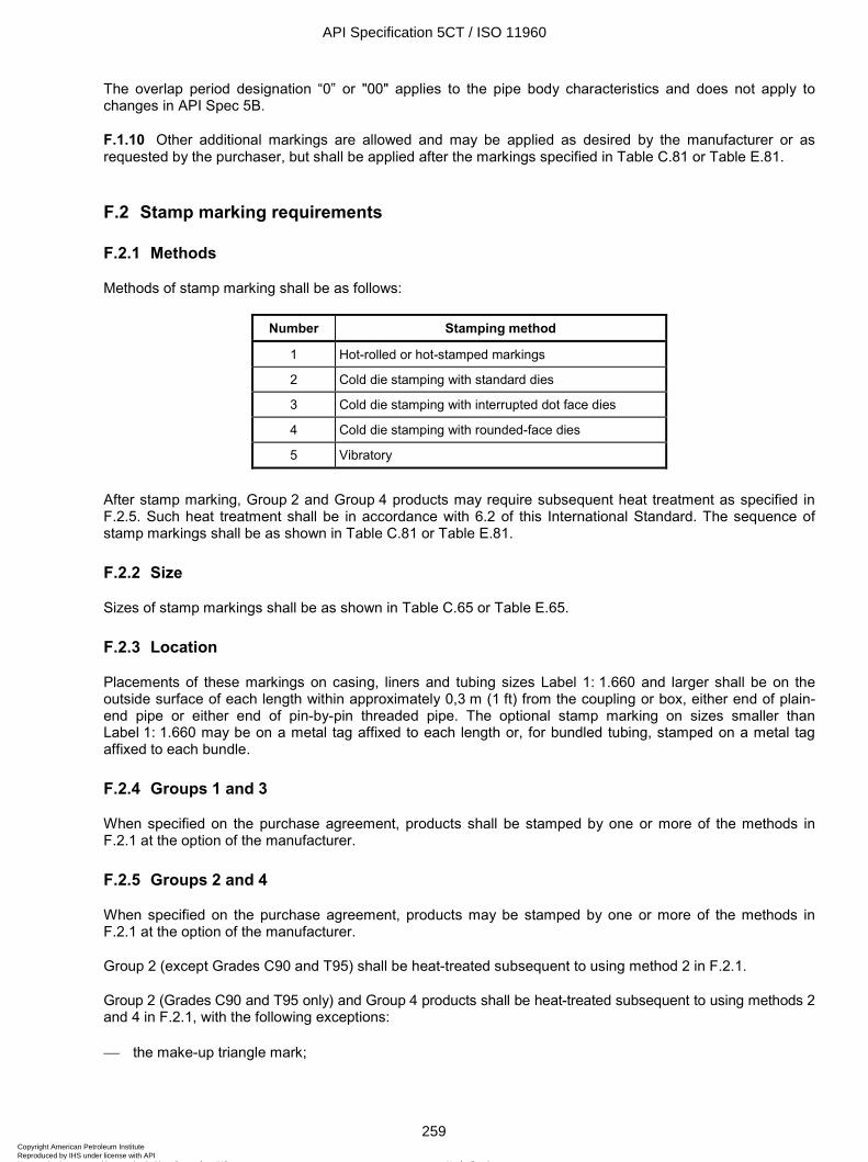
ISO 11960:2004(E)
© ISO 2004 – All rights reserved 259
The overlap period designation “0” or "00" applies to the pipe body characteristics and does not apply to changes in API Spec 5B.
F.1.10 Other additional markings are allowed and may be applied as desired by the manufacturer or as requested by the purchaser, but shall be applied after the markings specified in Table C.81 or Table E.81.
F.2 Stamp marking requirements
F.2.1 Methods
Methods of stamp marking shall be as follows:
Number Stamping method
1 Hot-rolled or hot-stamped markings
2 Cold die stamping with standard dies
3 Cold die stamping with interrupted dot face dies
4 Cold die stamping with rounded-face dies
5 Vibratory
After stamp marking, Group 2 and Group 4 products may require subsequent heat treatment as specified in F.2.5. Such heat treatment shall be in accordance with 6.2 of this International Standard. The sequence of stamp markings shall be as shown in Table C.81 or Table E.81.
F.2.2 Size
Sizes of stamp markings shall be as shown in Table C.65 or Table E.65.
F.2.3 Location
Placements of these markings on casing, liners and tubing sizes Label 1: 1.660 and larger shall be on the outside surface of each length within approximately 0,3 m (1 ft) from the coupling or box, either end of plain-end pipe or either end of pin-by-pin threaded pipe. The optional stamp marking on sizes smaller than Label 1: 1.660 may be on a metal tag affixed to each length or, for bundled tubing, stamped on a metal tag affixed to each bundle.
F.2.4 Groups 1 and 3
When specified on the purchase agreement, products shall be stamped by one or more of the methods in F.2.1 at the option of the manufacturer.
F.2.5 Groups 2 and 4
When specified on the purchase agreement, products may be stamped by one or more of the methods in F.2.1 at the option of the manufacturer.
Group 2 (except Grades C90 and T95) shall be heat-treated subsequent to using method 2 in F.2.1.
Group 2 (Grades C90 and T95 only) and Group 4 products shall be heat-treated subsequent to using methods 2 and 4 in F.2.1, with the following exceptions:
the make-up triangle mark;
API Specification 5CT / ISO 11960
259Copyright American Petroleum Institute Reproduced by IHS under license with API
Not for ResaleNo reproduction or networking permitted without license from IHS
--`,,,```-`-`,,`,,`,`,,`---
ISO 11960:2004(E)
260 © ISO 2004 – All rights reserved
when the stamp markings are removed by grinding, machining, threading or cropping to a depth not less than twice the depth of the stamping;
when not removing the stamping is by agreement between purchaser and manufacturer.
F.2.6 Make-up triangle marking
For buttress casing in all sizes and grades and for round thread casing in sizes Label 1: 16 and larger in Grades H40, J55, K55 and M65, the make-up triangle shall be stamped on the outside of each length on both ends. By agreement between purchaser and manufacturer, the make-up triangle may be replaced with a transverse white paint band 10 mm (3/8 in) wide by 76 mm (3 in) long. To assist in locating the triangle or transverse white paint band on buttress casing, a 25 mm (1 in) wide by 610 mm (24 in) long longitudinal white paint stripe shall be placed adjacent to the triangle or transverse paint band on the field end; additionally, a 25 mm (1 in) wide by 100 mm (4 in) long longitudinal white paint stripe shall be placed adjacent to the triangle or transverse paint band on the mill end.
For Groups 1 and 3, the triangle shall be stamped by method 2 or 4 only.
For Group 2 (Grades C90 and T95 only), the triangle shall be stamped by method 3 only.
For Group 2 (except Grades C90 and T95) and Group 4, the triangle shall be stamped by method 3 or 4 only.
F.3 Stencil marking requirements
Stencil markings shall be placed on the outside surface of each length of pipe, beginning at least 0,6 m (2 ft) from the coupling or box or from either end of plain-end pipe, pin-by-pin threaded pipe or coupling stock . For accessories and pup joints less than 1,8 m (6 ft) in length, the required stencil markings may be placed on a decal attached to the outside surface within 0,3 m (1 ft) of the end. These markings shall be separated by a dash or shall be adequately spaced.
The sequence of stencil markings shall be as specified in Table C.81 or Table E.81, except the thread marking shall be at a location convenient to the manufacturer.
F.4 Colour identification
F.4.1 Colour coding
Each product shall be colour-coded as described in F.4.2 to F.4.6, unless otherwise specified on the purchase agreement:
F.4.2 Product 1,8 m (6 ft) and longer
One or more of the following methods shall be used.
a) For threaded pipe, pup joints and accessories: paint a band encircling the product at a distance not greater than 0,6 m (24 in) from the coupling or internally threaded end.
b) For plain-end or pin-by-pin threaded product: paint a band encircling the product at a distance not greater than 0,6 m (24 in) from either end.
c) Coupling: paint the entire outside surface of the coupling, including the appropriate coupling colour bands.
d) If the pipe is furnished with special-clearance couplings or if the pipe and couplings are of a different grade (except Grades H40, J55 and K55 applied in accordance with 9.2.1), paint both the pipe and couplings as specified in items a), b) and c) above.
API Specification 5CT / ISO 11960
260Copyright American Petroleum Institute Reproduced by IHS under license with API
Not for ResaleNo reproduction or networking permitted without license from IHS
--`,,,```-`-`,,`,,`,`,,`---
ISO 11960:2004(E)
© ISO 2004 – All rights reserved 261
F.4.3 Loose couplings
Paint the entire surface of the coupling, including the appropriate colour bands.
F.4.4 Special-clearance couplings
Paint the colours indicative of the steel grade from which the couplings are manufactured and also paint a black band around the centre.
F.4.5 Pup joints and accessories shorter than 1,8 m (6 ft) in length
Paint the entire surface except the threads, including the appropriate colour bands.
F.4.6 Grade colour codes
The colour and number of bands used to represent each grade shall be as shown in Table C.66 or Table E.66.
F.5 Thread and end-finish marking — All groups
F.5.1 API thread marking
For manufacturers, thread identification shall be stencilled on casing with round, buttress or extreme-line threads. For threaders, thread identification is required on casing and tubing. This thread identification shall be as shown in Table C.67 or Table E.67.
F.5.2 Unfinished and special end-finish markings
Different marking is required for
a) plain-end pipe furnished either upset or non-upset or
b) pipe with special end-finish not specified herein but having the body of the pipe manufactured in accordance with the requirements specified herein or
c) completed couplings and completed accessories furnished with special end-finish not specified herein but which meet all the other requirements specified herein for these products except dimensions.
This marking shall be as shown in Table C.81 or Table E.81.
F.6 Pipe threader marking requirements — All groups
Pipe threaded by a facility other than the original pipe manufacturer shall be identified by a stamp or stencil consistent with F.1, F2 and F.3 adjacent to the threads with the name or mark of the threader, the specification mark, and size and type of thread as listed in F.5 and Table C.67 or Table E.67.
The threader shall mark on the body of the pipe the actual hydrostatic test pressure, unless the pipe has been previously tested to the pressure required for the thread as shown in Tables C.45 to C.61 or Tables E.45 to E.61 and marked as specified in Table C.81 or Table E.81.
API Specification 5CT / ISO 11960
261Copyright American Petroleum Institute Reproduced by IHS under license with API
Not for ResaleNo reproduction or networking permitted without license from IHS
--`,,,```-`-`,,`,,`,`,,`---
ISO 11960:2004(E)
262 © ISO 2004 – All rights reserved
EXAMPLE For Label 1: 7, Label 2: 29.00, C95, long-thread coupling:
Case 1) If the pipe manufacturer produced UF pipe and hydrostatic pressure-tested to 34,5 MPa (5 000 psi) based on the documented design basis of the tester for 177,8 mm (7 in) pipe (see 10.12.3), and marked P34,5 (P5000), then the threader shall pressure-test the pipe to 60,5 MPa (8 800 psi) and mark the pipe in accordance with Figure D.16.
Case 2) If the pipe manufacturer produced UF pipe and hydrostatic pressure tested to 61,0 MPa (8 900 psi) and marked the pipe P61,0 (P8900) then the threader is not required to pressure test or mark the test pressure.
The markings applied to the body of the pipe by the original pipe manufacturer shall not be removed or altered.
Use of the letters “API” to identify or certify that threads on tubular goods comply with API Spec 5B is not permitted.
API Specification 5CT / ISO 11960
262Copyright American Petroleum Institute Reproduced by IHS under license with API
Not for ResaleNo reproduction or networking permitted without license from IHS
--`,,,```-`-`,,`,,`,`,,`---
ISO 11960:2004(E)
© ISO 2004 – All rights reserved 263
Annex G (informative)
Procedures used to convert from USC units to SI units
G.1 Background
The following procedures were adopted in this International Standard for converting units from the United States Customary (USC) system into the Système Internationale (SI).
G.2 General
G.2.1 Rounding
The last retained digit in a number was unchanged when the next digit was less than 5 or raised when it was greater than 5.
When the digit following the last retained digit was exactly 5 followed by all zeros, the last retained digit was unchanged if it was even, or was raised if it was odd.
G.2.2 Fractions
Fractions or numbers with fractions in USC units were converted to the full decimal equivalents in USC units without rounding. The full decimal equivalents in USC units were then converted to SI values using the following formula:
Nm = 25,4 × N
where
Nm is the SI equivalent, expressed in millimetres, of a USC fraction or USC number with fractions (in inches);
N is the full decimal equivalent, expressed in inches, of a USC fraction or number with fractions which has not been rounded.
The converted SI values, in millimetres, for the equivalent of USC fractions or numbers with fractions were rounded to the appropriate number of places for the application.
G.2.3 Tolerances
The formula used was the same as that given in G.2.2.
The USC values for tolerances, except angular misalignment, were converted to SI values based on the appropriate conversion factor.
The converted SI values for the tolerances, except angular misalignment, were rounded to the same number of decimal places as the SI value to which they were applicable.
API Specification 5CT / ISO 11960
263Copyright American Petroleum Institute Reproduced by IHS under license with API
Not for ResaleNo reproduction or networking permitted without license from IHS
--`,,,```-`-`,,`,,`,`,,`---
ISO 11960:2004(E)
264 © ISO 2004 – All rights reserved
G.3 Pipe dimensions
G.3.1 Outside diameter
The USC values for outside diameters of pipe and couplings were converted to SI values using the following formula:
Dm = 25,4 × D
where
Dm is the outside diameter, expressed in millimetres;
D is the outside diameter, expressed in inches.
The converted SI values for the outside diameters of pipe and couplings were rounded to the nearest 0,01 mm.
G.3.2 Wall thickness
The USC values for wall thickness were converted to SI values using the following formula:
tm = 25,4 × t
where
tm is the wall thickness, expressed in millimetres;
t is the wall thickness, expressed in inches.
The converted SI values for wall thickness were rounded to the nearest 0,01 mm.
G.3.3 Inside diameter
The SI values for the inside diameters of pipe were calculated (not converted) using the following formula:
dm = Dm – (2 × tm)
where
dm is the inside diameter, expressed in millimetres;
Dm is the outside diameter, expressed in millimetres;
tm is the wall thickness, expressed in millimetres.
The calculated SI values for inside diameters of pipe were rounded to the nearest 0,01 mm.
G.3.4 Diameters and lengths of upsets
The USC values for the diameters and lengths of upsets were converted to SI values using the following formula:
Um = 25,4 × U
where
Um is the upset dimension, expressed in millimetres;
U is the upset dimension, expressed in inches.
API Specification 5CT / ISO 11960
264Copyright American Petroleum Institute Reproduced by IHS under license with API
Not for ResaleNo reproduction or networking permitted without license from IHS
--`,,,```-`-`,,`,,`,`,,`---
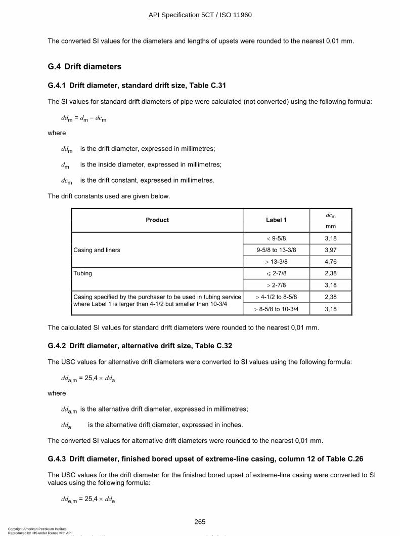
ISO 11960:2004(E)
© ISO 2004 – All rights reserved 265
The converted SI values for the diameters and lengths of upsets were rounded to the nearest 0,01 mm.
G.4 Drift diameters
G.4.1 Drift diameter, standard drift size, Table C.31
The SI values for standard drift diameters of pipe were calculated (not converted) using the following formula:
ddm = dm − dcm
where
ddm is the drift diameter, expressed in millimetres;
dm is the inside diameter, expressed in millimetres;
dcm is the drift constant, expressed in millimetres.
The drift constants used are given below.
dcm Product Label 1
mm
< 9-5/8 3,18
Casing and liners 9-5/8 to 13-3/8 3,97
> 13-3/8 4,76
u 2-7/8 2,38 Tubing
> 2-7/8 3,18
> 4-1/2 to 8-5/8 2,38 Casing specified by the purchaser to be used in tubing service where Label 1 is larger than 4-1/2 but smaller than 10-3/4
> 8-5/8 to 10-3/4 3,18
The calculated SI values for standard drift diameters were rounded to the nearest 0,01 mm.
G.4.2 Drift diameter, alternative drift size, Table C.32
The USC values for alternative drift diameters were converted to SI values using the following formula:
dda,m = 25,4 × dda
where
dda,m is the alternative drift diameter, expressed in millimetres;
dda is the alternative drift diameter, expressed in inches.
The converted SI values for alternative drift diameters were rounded to the nearest 0,01 mm.
G.4.3 Drift diameter, finished bored upset of extreme-line casing, column 12 of Table C.26
The USC values for the drift diameter for the finished bored upset of extreme-line casing were converted to SI values using the following formula:
dde,m = 25,4 × dde
API Specification 5CT / ISO 11960
265Copyright American Petroleum Institute Reproduced by IHS under license with API
Not for ResaleNo reproduction or networking permitted without license from IHS
--`,,,```-`-`,,`,,`,`,,`---
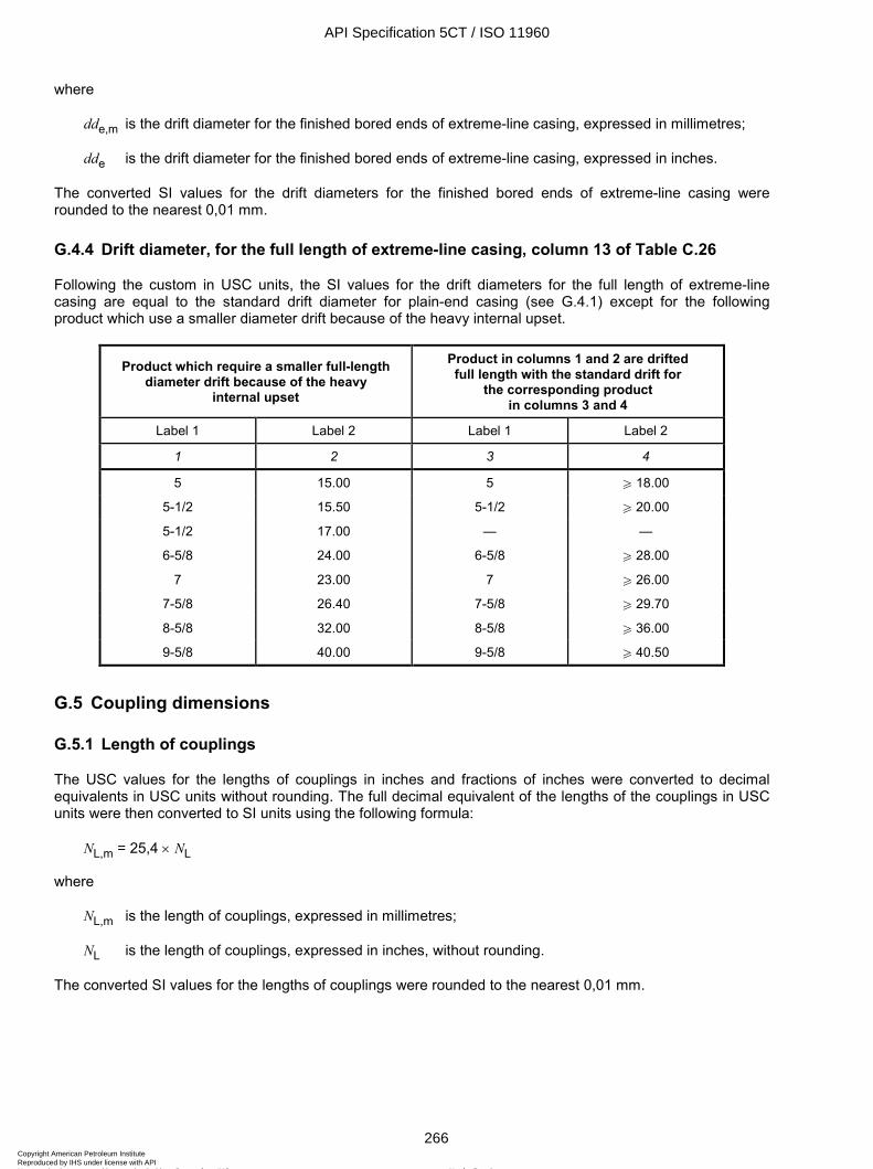
ISO 11960:2004(E)
266 © ISO 2004 – All rights reserved
where
dde,m is the drift diameter for the finished bored ends of extreme-line casing, expressed in millimetres;
dde is the drift diameter for the finished bored ends of extreme-line casing, expressed in inches.
The converted SI values for the drift diameters for the finished bored ends of extreme-line casing were rounded to the nearest 0,01 mm.
G.4.4 Drift diameter, for the full length of extreme-line casing, column 13 of Table C.26
Following the custom in USC units, the SI values for the drift diameters for the full length of extreme-line casing are equal to the standard drift diameter for plain-end casing (see G.4.1) except for the following product which use a smaller diameter drift because of the heavy internal upset.
Product which require a smaller full-length diameter drift because of the heavy
internal upset
Product in columns 1 and 2 are drifted full length with the standard drift for
the corresponding product in columns 3 and 4
Label 1 Label 2 Label 1 Label 2
1 2 3 4
5 15.00 5 W 18.00
5-1/2 15.50 5-1/2 W 20.00
5-1/2 17.00 — —
6-5/8 24.00 6-5/8 W 28.00
7 23.00 7 W 26.00
7-5/8 26.40 7-5/8 W 29.70
8-5/8 32.00 8-5/8 W 36.00
9-5/8 40.00 9-5/8 W 40.50
G.5 Coupling dimensions
G.5.1 Length of couplings
The USC values for the lengths of couplings in inches and fractions of inches were converted to decimal equivalents in USC units without rounding. The full decimal equivalent of the lengths of the couplings in USC units were then converted to SI units using the following formula:
NL,m = 25,4 × NL
where
NL,m is the length of couplings, expressed in millimetres;
NL is the length of couplings, expressed in inches, without rounding.
The converted SI values for the lengths of couplings were rounded to the nearest 0,01 mm.
API Specification 5CT / ISO 11960
266Copyright American Petroleum Institute Reproduced by IHS under license with API
Not for ResaleNo reproduction or networking permitted without license from IHS
--`,,,```-`-`,,`,,`,`,,`---
ISO 11960:2004(E)
© ISO 2004 – All rights reserved 267
G.5.2 Diameter of coupling recess
The USC values for diameters of the coupling recess were converted to SI values using the following formula:
Qm = 25,4 × Q
where
Qm is the diameter of the coupling recess, expressed in millimetres;
Q is the diameter of the coupling recess, expressed in inches.
The converted SI values for the diameters of the coupling recess were rounded to the nearest 0,01 mm.
G.5.3 Width of the coupling bearing face
The USC values for the widths of the bearing face of couplings were converted to SI values using the following formula:
bm = 25,4 × b
where
bm is the width of the coupling bearing face, expressed in millimetres;
b is the width of the coupling bearing face, expressed in inches.
The converted SI values for the widths of the coupling bearing faces were rounded to the nearest 0,01 mm.
G.5.4 Diameter at the root of the coupling thread at the end of the pipe in the power-tight position
The USC values for the diameter at the root of the coupling thread at the end of the pipe in the power-tight position were calculated without rounding and were then converted to SI values using the following formula:
d1m = 25,4 × d1
where
d1m is the diameter, expressed in millimetres, at the root of the coupling thread at the end of the pipe in the power-tight position;
d1 is the unrounded diameter, expressed in inches, at the root of the coupling thread at the end of the pipe in the power-tight position.
The converted SI values for the diameter at the root of the coupling thread at the end of the pipe in the power-tight position were rounded to the nearest 0,01 mm.
G.6 Linear mass
G.6.1 Nominal threaded and coupled linear mass
The USC values for nominal threaded and coupled linear mass were converted to SI units using the following formula:
wm = 1,488 16 × w
API Specification 5CT / ISO 11960
267Copyright American Petroleum Institute Reproduced by IHS under license with API
Not for ResaleNo reproduction or networking permitted without license from IHS
--`,,,```-`-`,,`,,`,`,,`---
ISO 11960:2004(E)
268 © ISO 2004 – All rights reserved
where
wm is the linear mass, expressed in kilograms per metre;
w is the linear mass, expressed in pounds per foot.
The converted SI values for nominal threaded and coupled linear mass were rounded to the nearest 0,01 kg/m.
G.6.2 Plain-end linear mass
The plain-end linear masses expressed in SI units were calculated (not converted) using the following formula:
wpe,m = 0,024 661 5 × (Dm − tm) × tm
where
wpe,m is the plain-end linear mass, expressed in kilograms per metre;
Dm is the outside diameter, expressed in millimetres;
tm is the wall thickness, expressed in millimetres.
The calculated SI values for plain-end linear masses were rounded to the nearest 0,01 kg/m.
G.6.3 Coupling masses
The USC values for the calculated masses of couplings were converted to SI values using the following formula:
mc,m = 0,453 592 × mc
where
mc,m is the mass of the coupling, expressed in kilograms;
mc is the mass of the coupling, expressed in pounds.
The converted SI values for calculated masses of couplings were rounded to the nearest 0,01 kg.
G.6.4 Mass gain or loss due to end finish
The USC values for mass gain or loss due to end finish were converted to SI units using the following formula:
ee,m = 0,453 592 × ee
where
ee,m is the mass gain or loss due to end finish, expressed in kilograms;
ee is the mass gain or loss due to end finish, expressed in pounds.
The converted SI values for mass gain or loss due to end finish were rounded to the nearest 0,01 kg.
API Specification 5CT / ISO 11960
268Copyright American Petroleum Institute Reproduced by IHS under license with API
Not for ResaleNo reproduction or networking permitted without license from IHS
--`,,,```-`-`,,`,,`,`,,`---
ISO 11960:2004(E)
© ISO 2004 – All rights reserved 269
G.7 Tensile and flattening tests
G.7.1 Yield strength
The USC values for yield strength were converted to SI values using the following formula:
YSm = 0,006 894 76 × YS
where
YSm is the yield strength, expressed in megapascals;
YS is the yield strength, expressed in pounds per square inch.
The converted SI values for strengths were rounded to the nearest megapascal.
G.7.2 Tensile strength
The USC values for tensile strength were converted to SI values using the following formula:
TSm = 0,006 894 76 × TS
where
TSm is the tensile strength, expressed in megapascals;
TS is the tensile strength, expressed in pounds per square inch.
The converted SI values for strengths were rounded to the nearest megapascal.
G.7.3 Elongation
The values for elongation, in SI units, were calculated (not converted) using the following formula:
em = 1 944 × Am0,2/Um
0,9
where
em is the minimum elongation, expressed as a percentage;
Am is the cross-sectional area of the tensile specimen, expressed in square millimetres;
Um is the specified minimum tensile strength, expressed in megapascals.
The calculated SI values for elongation were rounded to the nearest 1,0 % for values of 10,0 % and larger, and to the nearest 0,5 % for values less than 10,0 %.
G.7.4 Flattening test formula
The formula used to determine the maximum distance between the plates during a flattening test had the following form:
Df = D × [Z1 – (Z2 × D / t)]
API Specification 5CT / ISO 11960
269Copyright American Petroleum Institute Reproduced by IHS under license with API
Not for ResaleNo reproduction or networking permitted without license from IHS
--`,,,```-`-`,,`,,`,`,,`---
ISO 11960:2004(E)
270 © ISO 2004 – All rights reserved
where
Df is the maximum distance between the plates during a flattening test, expressed in inches or millimetres depending on the units of D and t ;
Z1 is a constant;
Z2 is a constant;
D is the specified outside diameter of the pipe, expressed in inches or millimetres;
t is the specified wall thickness of the pipe, expressed in inches or millimetres.
The same values for the constants Z1 and Z2 were used regardless of whether the units for D and t were inches or millimetres, provided the units for both D and t were the same.
G.8 Charpy impact energy requirements
G.8.1 Critical thickness for couplings with API threads, Table C.8
The USC values for the critical thickness for couplings with API threads were converted to SI values using the following formula:
tc,m = 25,4 × tc
where
tc,m is the critical thickness, expressed in millimetres;
tc is the critical thickness, expressed in inches.
The calculated SI values were rounded to the nearest 0,01 mm.
G.8.2 Charpy impact energy
The USC values for standard CVN impact energy requirements that are not determined by an equation (for example, as used in Table C.11 and other minimum requirements) were converted to SI values using the following formula:
Cm = 1,355 82 × C
where
Cm is the standard Charpy impact energy, expressed in joules;
C is the standard Charpy impact energy, expressed in foot-pounds (e.g. 8, 15, 20, 30 ft-lb).
The converted SI values for standard CVN impact energy were rounded to the nearest joule.
G.8.3 Minimum absorbed energy requirements for couplings, Tables C.12 to C.18
The SI values for the minimum absorbed energy requirements for couplings with API threads were calculated using the following formulae:
For Grades N80 Type 1, N80Q, L80, C90, C95, T95, P110 and Q125
API Specification 5CT / ISO 11960
270Copyright American Petroleum Institute Reproduced by IHS under license with API
Not for ResaleNo reproduction or networking permitted without license from IHS
--`,,,```-`-`,,`,,`,`,,`---
ISO 11960:2004(E)
© ISO 2004 – All rights reserved 271
Transverse Charpy absorbed energy requirements for couplings:
Cctm = fc × YSmax × [(0,001 18 × tc) + 0,012 59]
Longitudinal Charpy absorbed energy requirements for couplings
Cclm = fc × YSmax × [(0,002 36 × tc) + 0,025 18]
where
Cctm is the minimum transverse Charpy impact energy for couplings, expressed in joules;
Cclm is the minimum longitudinal Charpy impact energy for couplings, expressed in joules;
YSmax is the specified maximum yield strength of the coupling, expressed in megapascals;
tc is the critical thickness shown in Table C.8 for couplings with API threads, expressed in millimetres;
fc is a factor depending on the size of the Charpy impact specimen:
1,00 for full-size specimens (10 mm × 10 mm);
0,80 for ¾-size specimens (10 mm × 7,5 mm);
0,55 for ½-size specimens (10 mm × 5 mm).
The calculated SI values were rounded to the nearest joule.
NOTE 1 The maximum-size fully machined transverse and longitudinal Charpy impact specimens for couplings for API threads can be found in API Bull 5C3. These sizes are included in Tables C.12 to C.16 and used in the calculation of the Charpy requirements shown in those tables.
NOTE 2 The absorbed energy requirements in Tables C.17 and C.18 are for full-size test specimens where the factor f is set to 1,00.
G.8.4 Absorbed energy requirements for pipe
The SI values for the maximum specified wall thickness for various grades of pipe for minimum absorbed energy values from full-size test specimens were calculated based on the equations given in a) and b) below. In these equations the following is applicable:
Cpt,m is the minimum transverse Charpy impact energy for pipe, expressed in joules;
Cpl,m is the minimum longitudinal Charpy impact energy for pipe, expressed in joules;
YSmax is the specified maximum yield strength of the pipe, expressed in megapascals;
YSmin is the specified minimum yield strength of the pipe, expressed in megapascals.
The rounding procedures of ISO 31-0 or ASTM E29 shall be followed. For example, when calculating the requirements for 27 J, 27,499 999 99 should be used for Cpt,m or Cpl,m (since that rounds to 27). Similarly, when calculating the requirements for 28 J, 28,500 000 00 should be used for Cpt,m or Cpl,m (since that rounds to 28). The wall thickness that results from the calculation shall be rounded down to two decimal places.
a) Grades N80Q, L-80, C90, C95, T95 and P110
Transverse Charpy absorbed energy requirements for pipe, Table C.19:
t = [(Cpt,m/YSmin) – 0,012 59] / 0,001 18
API Specification 5CT / ISO 11960
271Copyright American Petroleum Institute Reproduced by IHS under license with API
Not for ResaleNo reproduction or networking permitted without license from IHS
--`,,,```-`-`,,`,,`,`,,`---
ISO 11960:2004(E)
272 © ISO 2004 – All rights reserved
Longitudinal Charpy absorbed energy requirements for pipe, Table C.20:
t = [(Cpl,m/YSmin) – 0,025 18] / 0,002 36
b) Grade Q125
Transverse Charpy absorbed energy requirements for pipe, Table C.19:
t = [(Cpt,m/YSmax) – 0,012 59] / 0,001 18
Longitudinal Charpy absorbed energy requirements for pipe, Table C.20:
t = [(Cpl,m/YSmax) – 0,025 18] / 0,002 36
G.8.5 Calculated wall thickness required to machine transverse and longitudinal Charpy impact specimens from pipe and couplings, Tables C.21 and C.22
The SI values for the wall thicknesses required to machine transverse and longitudinal Charpy impact test specimens from pipe and couplings were calculated using the following formulae:
Transverse Charpy impact specimens, Table C.21:
tt = (Dm/2) – [(Dm/2)2 – 756,25]0,5 + 1,00 + wCs
Longitudinal Charpy impact specimens, Table C.22:
tl = (Dm/2) – [(Dm/2)2 – 25]0,5 + 1,00 + wCs
where
tt is the calculated value for the wall thickness, expressed in millimetres, required to machine transverse Charpy impact test specimens from pipe and couplings;
tl is the calculated value for the wall thickness, expressed in millimetres, required to machine longitudinal Charpy impact test specimens from pipe and couplings;
Dm is the specified outside diameter of the pipe or coupling, expressed in millimetres;
wCs is the width of the Charpy impact test specimen, expressed in millimetres:
10,0 mm for full-size specimens;
7,5 mm for ¾-size specimens;
5,0 mm for ½-size specimens.
In the above formulae, a machining allowance of 1,00 mm is included (USC formulae allowed 0,020 in on the inside pipe surface and 0,020 in on the outside surface or 1,00 mm total for the purposes of this calculation).
The calculated SI values for the wall thicknesses required to machine transverse and longitudinal Charpy impact test specimens from pipe and couplings were rounded to the nearest 0,01 mm.
API Specification 5CT / ISO 11960
272Copyright American Petroleum Institute Reproduced by IHS under license with API
Not for ResaleNo reproduction or networking permitted without license from IHS
--`,,,```-`-`,,`,,`,`,,`---
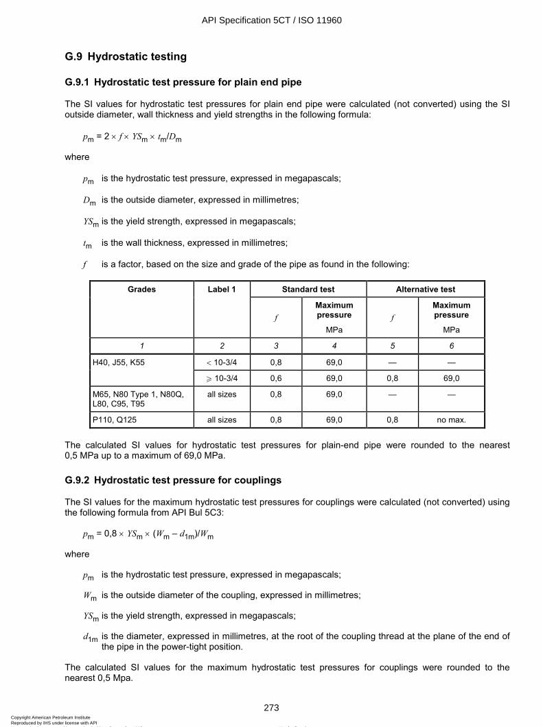
ISO 11960:2004(E)
© ISO 2004 – All rights reserved 273
G.9 Hydrostatic testing
G.9.1 Hydrostatic test pressure for plain end pipe
The SI values for hydrostatic test pressures for plain end pipe were calculated (not converted) using the SI outside diameter, wall thickness and yield strengths in the following formula:
pm = 2 × f × YSm × tm/Dm
where
pm is the hydrostatic test pressure, expressed in megapascals;
Dm is the outside diameter, expressed in millimetres;
YSm is the yield strength, expressed in megapascals;
tm is the wall thickness, expressed in millimetres;
f is a factor, based on the size and grade of the pipe as found in the following:
Standard test Alternative test Grades Label 1
f Maximum pressure
MPa f
Maximum pressure
MPa
1 2 3 4 5 6
< 10-3/4 0,8 69,0 — — H40, J55, K55
W 10-3/4 0,6 69,0 0,8 69,0
M65, N80 Type 1, N80Q, L80, C95, T95
all sizes 0,8 69,0 — —
P110, Q125 all sizes 0,8 69,0 0,8 no max.
The calculated SI values for hydrostatic test pressures for plain-end pipe were rounded to the nearest 0,5 MPa up to a maximum of 69,0 MPa.
G.9.2 Hydrostatic test pressure for couplings
The SI values for the maximum hydrostatic test pressures for couplings were calculated (not converted) using the following formula from API Bul 5C3:
pm = 0,8 × YSm × (Wm – d1m)/Wm
where
pm is the hydrostatic test pressure, expressed in megapascals;
Wm is the outside diameter of the coupling, expressed in millimetres;
YSm is the yield strength, expressed in megapascals;
d1m is the diameter, expressed in millimetres, at the root of the coupling thread at the plane of the end of the pipe in the power-tight position.
The calculated SI values for the maximum hydrostatic test pressures for couplings were rounded to the nearest 0,5 Mpa.
API Specification 5CT / ISO 11960
273Copyright American Petroleum Institute Reproduced by IHS under license with API
Not for ResaleNo reproduction or networking permitted without license from IHS
--`,,,```-`-`,,`,,`,`,,`---
ISO 11960:2004(E)
274 © ISO 2004 – All rights reserved
G.9.3 Internal pressure leak-resistance at E1 or E7 plane
The SI values for internal pressure leak-resistance at the E1 plane of round thread connections and at the E7 plane of buttress thread casing were calculated (not converted) using the following formula from API Bul 5C3:
pLRm = E × T × N × P × [Wm2 - Es
2] / [2 × Es × Wm2]
where
pLRm is the internal pressure leak-resistance at the E1 or E7 plane, expressed in megapascals;
Wm is the outside diameter of the coupling, expressed in millimetres;
YSm is the yield strength, expressed in megapascals;
d1m is the diameter, expressed in millimetres, at the root of the coupling thread at the plane of the end of the pipe in the power-tight position;
E is the modulus of elasticity, 207 000 MPa;
Es is the pitch diameter at the seal, expressed in millimetres:
E1 for round threads;
E7 for buttress threads;
N is the number of power turns;
P is the thread pitch, expressed in inches per thread;
T is the thread taper, expressed in inches per inch.
The calculated SI values for internal pressure leak-resistance limits were rounded to the nearest 0,5 MPa.
G.9.4 Hydrostatic test pressure for threaded and coupled pipe
The hydrostatic test pressure for threaded and coupled pipe is the lowest pressure of:
the hydrostatic test pressure for plain-end pipe,
the maximum hydrostatic test pressure for couplings, or
the internal pressure leak-resistance.
G.10 Other
G.10.1 Temperature
The temperatures in degrees Fahrenheit (USC) were converted to temperatures in degrees Celsius (SI) using the following formula:
∞C = (∞F – 32) × 5/9
where
∞C is the temperature, expressed in degrees Celsius;
∞F is the temperature, expressed in degrees Fahrenheit.
API Specification 5CT / ISO 11960
274Copyright American Petroleum Institute Reproduced by IHS under license with API
Not for ResaleNo reproduction or networking permitted without license from IHS
--`,,,```-`-`,,`,,`,`,,`---
ISO 11960:2004(E)
© ISO 2004 – All rights reserved 275
The converted SI values for temperatures were rounded to the nearest degree.
When the temperature being converted was over 600 ∞F, the number was rounded to the most rational value rounded to the nearest 5 ∞C. For example, 750 ∞F converts to 399 ∞C but the rational conversion is 400 ∞C.
G.10.2 Torque
The USC values for make-up torque may be converted to SI values using the following formula:
Tm = 1,355 82 × T
where
Tm is the torque, expressed in newton-metres;
T is the torque, expressed in foot-pounds.
The converted SI values for make-up torque may be rounded to the nearest newton metre.
NOTE This International Standard does not include requirements for torque. However, as this International Standard is the primary casing and tubing standard, a conversion procedure for torque is included here for convenience of the user.
API Specification 5CT / ISO 11960
275Copyright American Petroleum Institute Reproduced by IHS under license with API
Not for ResaleNo reproduction or networking permitted without license from IHS
--`,,,```-`-`,,`,,`,`,,`---
ISO 11960:2004(E)
276 © ISO 2004 – All rights reserved
Annex H (normative)
Product Specification Levels
H.1 General
This annex describes Product Specification Level (PSL) requirements for PSL-2 and PSL-3, for all Grades except H-40 and L-80 9Cr, that may be specified by the purchaser. Higher PSL requirements may be furnished at the option of the manufacturer. The requirements for PSL-2 and PSL-3 are in addition to those for PSL-1, which are the basis of this International Standard. All requirements for PSL-3 are in addition to requirements for PSL-2, except as otherwise indicated by PLS-3 requirements. Accordingly, in the body of this International Standard, clauses and subclauses that give additional PSL-3 requirements are identified as only PSL-3. Those clauses and subclauses that give PSL-2 requirements are identified as both PSL-2 and PSL-3.
Table H.1, at the end of this annex, is a reference table for PSL-2 and PSL-3 requirements.
NOTE The numbers in parentheses following titles to clauses and subclauses in this annex are the paragraph numbers in the body of this International Standard which are amended by the requirements of the PSL.
H.2 Heat treatment
H.2.1 Grade J55 and K55, PSL-2 (6.2.2)
Product shall be full-body normalized or normalized and tempered and, if upset, shall be normalized or normalized and tempered after upsetting.
H.2.2 Grade N80Q, PSL-3 (6.2.2)
Only Grade N80Q shall be furnished for PSL-3.
H.3 Straightening, PSL-2
H.3.1 Grades C90 and T95 (6.3.4)
Product, when necessary, shall be either cold rotary straightened followed by stress relief at 30 ºC to 56 ºC (50 ºF to 100 ºF) below the final specified temper temperature, or hot rotary straightened with an exit temperature not more than 165 ºC (300 ºF) below the final specified temper temperature. When necessary, light gag straightening shall be permitted.
H.3.2 Grades C95 and P110 (6.3.1, 6.3.3)
Gag press straightening or hot rotary straightening [400 ºC (750 ºF) minimum at end of rotary straightening unless a higher minimum temperature is specified on the purchase agreement] is acceptable. If hot rotary straightening is not possible, the pipe may be cold rotary straightened provided it is then stress-relieved at 510 ºC (950 ºF) or higher.
API Specification 5CT / ISO 11960
276Copyright American Petroleum Institute Reproduced by IHS under license with API
Not for ResaleNo reproduction or networking permitted without license from IHS
--`,,,```-`-`,,`,,`,`,,`---
ISO 11960:2004(E)
© ISO 2004 – All rights reserved 277
H.4 Chemical composition (7.1)
H.4.1 Grades C90, T95, and Q125 PSL-2
Chemical composition shall be Type 1.
H.4.2 Grades C90 and T95, PSL-3
The manufacturer shall inform the purchaser at the time of inquiry of the minimum and maximum concentrations for all elements deliberately added to each heat, regardless of the purpose of the addition.
H.5 Yield strength — Grade Q125, PSL-3 (7.2.3)
The maximum yield strength shall be 965 MPa (140 ksi).
H.6 Charpy V-notch tests
H.6.1 Charpy V-notch test properties — General requirements, Grades N80 Type 1, N80Q, L80 Type 1, C90, C95, T95, P110 and Q125, PSL-2 (7.3.1)
In order to meet the test requirement, a 75 % minimum shear area is necessary, in accordance with ASTM E23.
H.6.2 Charpy V-notch — Absorbed energy requirements for pipe, PSL-2
H.6.2.1 All grades except M65 and Q125 (7.5.1 and 7.5.3)
Impact testing shall be carried out in accordance with A.10 (SR16). The test temperature shall be 21 °C (70 °F) for Grades J55 and K55 and 0 °C (32 °F) for all other grades, or a lower temperature by agreement between purchaser and manufacturer.
H.6.2.2 Grade Q125 (7.5.4)
Statistical impact testing is required in accordance with A.7 (SR12).
H.7 Hardenability — Minimum percentage martensite required for quenched and tempered products
H.7.1 Grade L80 Type 1, PSL-2 (7.10.2)
A full-body as-quenched sample shall be taken in accordance with a documented procedure to confirm sufficient hardening for each size, mass, chemical composition, and austenitize and quench combination. To be in compliance with this International Standard, the mean hardness numbers (see 10.6.10) obtained during the documented procedure shall equal or exceed the hardness corresponding to 90 % minimum martensite, as determined by the following equation:
HRCmin = 58 × (% carbon) + 27
API Specification 5CT / ISO 11960
277Copyright American Petroleum Institute Reproduced by IHS under license with API
Not for ResaleNo reproduction or networking permitted without license from IHS
--`,,,```-`-`,,`,,`,`,,`---
ISO 11960:2004(E)
278 © ISO 2004 – All rights reserved
H.7.2 Grades C90 AND T95, PSL-3 (7.10.1)
The mean hardness numbers obtained as specified in H.7.1 shall equal or exceed the hardness corresponding to a minimum of 95 % martensite as determined by the following equation:
HRCmin = 59 × (% carbon) + 29
For pipes with a wall thickness of 30 mm (1.181 in) or larger, an alternative requirement may be used by agreement between manufacturer and purchaser.
H.8 Inside surface preparation — Grade L80 13Cr, PSL-2 (7.12)
The pipe inside surface properties shall meet the requirements for Sa 2½ in ISO 8501-1. During surface preparation, any blasting media that may cause surface iron contamination shall not be used.
H.9 Sulfide stress-cracking (SSC) test — PSL-3
H.9.1 Grades C90 and T95 (7.14)
If Method A is specified for the SSC test (in accordance with ANSI-NACE TM0177-96), manufacturers shall for each heat demonstrate that the product meets or exceeds the 90 % YSmin threshold for three specimens, one each from the ends of three different pipes selected from the start, middle and end of the heat/heat treatment lot. A retest of one specimen may be carried out if only one of the initial samples fails. If the retest specimen fails, the heat shall be rejected.
By agreement between the purchaser and manufacturer, the number of specimens per heat/heat treatment lot required may be reduced to no less than one with a process control plan that is sufficient to ensure that the product meets or exceeds the 90 % YSmin threshold.
H.9.2 Grade L80 13Cr
If requested by the purchaser, the manufacturer shall for each heat demonstrate that the product meets or exceeds the 80 % SMYS threshold using test Method A in accordance with ANSI-NACE TM0177-96. The test solution shall have a pH of 3,5 and a partial pressure of H2S of 10 kPa (1.5 psi).
H.10 Processing of pin ends — All groups, PSL-2 (8.12.7)
Pin threads shall be abrasive-blasted unless processed by any appropriate technique, including primary machining, which has been agreed between the purchaser and manufacturer to be sufficient to avoid the presence of material susceptible to detaching or causing galling during make-up.
H.11 Seal-ring couplings — All groups, PSL-2 (9.11)
Seal-ring grooves shall be machined in the same set-up used to machine the box threads. The seal-ring groove eccentricity shall be no greater than 0,13 mm (0.005 in) and shall be verified for each machine set-up. Seal-ring groove eccentricity is the maximum difference between the values of the distance from the root of the seal-ring groove to the minor cone of the coupling threads in a plane at any location around the circumference.
API Specification 5CT / ISO 11960
278Copyright American Petroleum Institute Reproduced by IHS under license with API
Not for ResaleNo reproduction or networking permitted without license from IHS
--`,,,```-`-`,,`,,`,`,,`---
ISO 11960:2004(E)
© ISO 2004 – All rights reserved 279
H.12 Processing of box ends — All groups, PSL-2 (9.13.1)
Box threads shall be abrasive-blasted unless processed by any appropriate technique, including primary machining, which has been agreed between the purchaser and manufacturer to be sufficient to avoid the presence of material susceptible to detaching or causing galling during make-up.
H.13 Frequency of tensile testing — Casing and tubing, Grades N80 Type 1, and N80Q, PSL-2 (10.4.3)
The frequency of testing shall be the same as for Grade L80 Type 1.
H.14 Hardness testing, PSL-3
H.14.1 Hardness test — Grades N80Q, L80 Type 1, C95, P110 and Q125 (10.6.1, 10.6.4 and 10.6.8)
The manufacturer shall apply a process control plan which has been demonstrated to the satisfaction of the purchaser as sufficient to ensure that each pipe body, each upset and each coupling has mechanical properties conforming to the requirements of this International Standard. If this condition is not fulfilled, each pipe body, each upset and each coupling shall be surface-hardness-tested. Hardness minimum and maximum values, when not specified in this International Standard, shall be in accordance with the manufacturer’s specifications or by agreement between the purchaser and the manufacturer.
H.14.2 Sampling and test specimen location — Non-upset pipe, Grades C90 and T95 (10.6.5)
A test ring shall be cut from both ends of each pipe.
H.15 Metallographic evaluation for EW pipe — Grades J55, K55, M65, N80 Type 1, N80Q, L80 Type 1, and C95, PSL-2 (10.11)
A metallographic evaluation shall be performed at the beginning of the welding process for each size of tubular, at least every 4 h during the welding and after any substantial interruption of the welding process. The samples shall be obtained prior to heat treatment.
H.16 Hydrostatic test — Grades J55 and K55, PSL-2 (10.12.2)
Alternative test pressures shall be used for sizes above Label 1: 9-5/8.
H.17 Wall thickness (10.13.4)
H.17.1 All groups, PSL-2
Wall thickness shall be measured and recorded for the full length, with a minimum coverage of 25 % of the surface area covered by the automatic system.
H.17.2 All groups, PSL-3
Wall thickness shall be measured and recorded for the full length, with a minimum coverage of 100 % of the surface area covered by the automatic system. The minimum measured wall thickness for each pipe shall be reported. Traceability per pipe is not required.
API Specification 5CT / ISO 11960
279Copyright American Petroleum Institute Reproduced by IHS under license with API
Not for ResaleNo reproduction or networking permitted without license from IHS
--`,,,```-`-`,,`,,`,`,,`---
ISO 11960:2004(E)
280 © ISO 2004 – All rights reserved
H.18 Non-destructive examination (NDE)
H.18.1 Full-body NDE — Casing and tubing
H.18.1.1 Grades J55 and K55, PSL-2 (10.15.5)
All pipe shall be inspected for the detection of longitudinal imperfections on the outside and inside surfaces to acceptance level L4 by one or more of the methods specified in 10.15.5.
H.18.1.2 Grades M65, N80 Type 1 and N80Q, PSL-2 (10.15.5 and 10.15.6)
All pipe shall be inspected for the detection of longitudinal and transverse imperfections on the outside and inside surfaces to acceptance level L3 by ultrasonic or EMI testing in accordance with A.2 (SR1).
H.18.1.3 Grades L80 Type 1, L80 13CR, and C95, PSL2 (10.15.6)
All pipe shall be inspected for the detection of both longitudinal and transverse imperfections on the outside and inside surfaces to acceptance level L2 by one or more of the methods specified in 10.15.8. Magnetic particle testing is only allowed as a second full-length inspection.
H.18.1.4 Grades J55, K55, and M65, PSL-3 (10.15.5 and 10.15.6)
All pipe shall be inspected for the detection of both longitudinal and transverse imperfections on the outside and inside surfaces to acceptance level L2 by one or more of the methods specified in 10.15.6 a, b, or c. Magnetic particle testing is only allowed as a second full-length inspection.
H.18.1.5 Grades N80Q, L80 Type 1, L80 13CR, C95, and P110, and P110 A.10 (SR16), PSL-3 (10.15.6, 10.15.7 and 10.15.8)
All pipe shall be inspected for the detection of both longitudinal and transverse imperfections on the outside and inside surfaces to acceptance level L2 in accordance with ISO 9303 or ASTM E213 (longitudinal) and ISO 9305 or ASTM E213 (transverse).
In addition, all pipe shall be inspected for the detection of imperfections on the outside surface by one of the methods in 10.15.9.
H.18.2 NDE of the weld seam of welded pipe — Grades K55 and M65, PSL-2 (10.15.10)
The weld seam inspection required by this International Standard shall be performed after the hydrostatic test using ultrasonic test methods.
H.18.3 NDE of untested pipe ends — All groups, PSL-3 (10.15.12)
The inspection of untested end area shall be performed using the wet magnetic particle method, or a method agreed between purchaser and manufacturer, after end-finishing and before coupling installation of threaded and coupled tubulars.
H.18.4 NDE of coupling stock — Groups 2, 3 and 4, PSL-2 (10.15.11)
H.18.4.1 Permitted imperfections before machining
Coupling stock for couplings that will be fully machined may have imperfections on the unmachined surfaces, however the final machined surfaces shall meet the specified dimensions and the surface inspection criteria of 9.14 (A.4.3 SR9.3).
API Specification 5CT / ISO 11960
280Copyright American Petroleum Institute Reproduced by IHS under license with API
Not for ResaleNo reproduction or networking permitted without license from IHS
--`,,,```-`-`,,`,,`,`,,`---
ISO 11960:2004(E)
© ISO 2004 – All rights reserved 281
H.18.4.2 Further evaluation
Coupling stock containing defects may be given further evaluation in accordance with 10.15.14, except the maximum size of the non-surface-breaking imperfection specified in 8.13.1 c) shall be reduced to 32 mm2 (0.05 in2). Coupling stock containing defects shall either be given disposition in accordance with 10.15.17, or the section of coupling stock containing the defect shall be cut off within the limits of the requirements on length specified on the coupling stock purchase agreement.
H.18.4.3 Ultrasonic testing — Through-wall
Coupling stock shall be inspected full length for the entire through-wall thickness, from the OD surface to the FBH reference indicator, by the manufacturer using ultrasonic compression-wave techniques to detect and identify imperfections.
Reference indicator Metal distance a Minimum coverage b
6,4 mm (1/4 in) ID FBH (one only) 90 % 25 % a Distance from the OD surface to the bottom of the FBH, expressed as a percent of the specified minimum wall thickness. The metal distance tolerance shall be ± 1,5 % of the calculated metal distance. b Determine coverage in accordance with 10.15.4 a).
H.18.4.4 Ultrasonic testing — Inside surface
Coupling stock shall be inspected for longitudinal and transverse imperfections on the inside surface using ultrasonic shear-wave techniques to acceptance level L4. By agreement between the purchaser and manufacturer, alternative NDE methods which demonstrate the capability to detect the reference indicators may be used.
H.18.5 NDE of coupling stock — Groups 2, 3 and 4, PSL-3 (10.15.11)
H.18.5.1 Minimum coverage
Coupling stock shall be inspected in accordance with H.18.4.3, except the minimum coverage shall be 100 %.
H.18.5.2 Acceptance level
Coupling stock shall be inspected in accordance with H.18.4.4, except the acceptance level shall be L3 with a maximum notch length of 25 mm (1 in).
H.19 Thread protectors — All grades, PSL-2 (12.2.1)
Thread protectors shall meet the requirement of annex I or be as specified on the purchase agreement.
H.20 Certification requirements — Groups 1, 2 and 3, PSL-2 (13.2)
Certification shall be provided by the manufacturer for all product shipped. The requirements of A.9 (SR15) shall apply.
H.21 Non-metallic seal ring — All groups, PSL-2 (A.8.2)
Seal rings for field-end box threads shall be shipped separately in a sealed package labelled with the quantity, connection description, connection manufacturer, date inspected, and date packaged.
API Specification 5CT / ISO 11960
281Copyright American Petroleum Institute Reproduced by IHS under license with API
Not for ResaleNo reproduction or networking permitted without license from IHS
--`,,,```-`-`,,`,,`,`,,`---
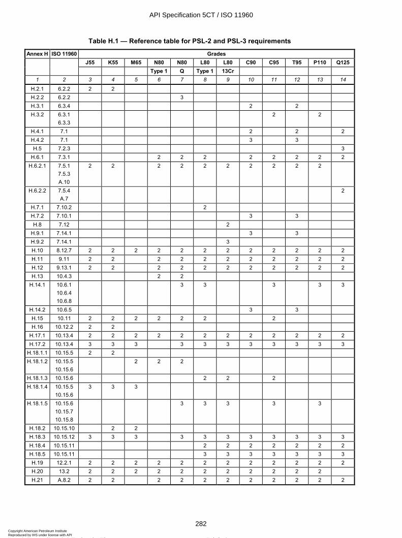
ISO 11960:2004(E)
282 © ISO 2004 – All rights reserved
Table H.1 — Reference table for PSL-2 and PSL-3 requirements
Annex H ISO 11960 Grades J55 K55 M65 N80 N80 L80 L80 C90 C95 T95 P110 Q125
Type 1 Q Type 1 13Cr
1 2 3 4 5 6 7 8 9 10 11 12 13 14
H.2.1 6.2.2 2 2 H.2.2 6.2.2 3 H.3.1 6.3.4 2 2 H.3.2 6.3.1
6.3.3 2 2
H.4.1 7.1 2 2 2 H.4.2 7.1 3 3 H.5 7.2.3 3
H.6.1 7.3.1 2 2 2 2 2 2 2 2 H.6.2.1 7.5.1
7.5.3 A.10
2 2 2 2 2 2 2 2 2 2
H.6.2.2 7.5.4 A.7
2
H.7.1 7.10.2 2 H.7.2 7.10.1 3 3 H.8 7.12 2
H.9.1 7.14.1 3 3 H.9.2 7.14.1 3 H.10 8.12.7 2 2 2 2 2 2 2 2 2 2 2 2 H.11 9.11 2 2 2 2 2 2 2 2 2 2 2 H.12 9.13.1 2 2 2 2 2 2 2 2 2 2 2 H.13 10.4.3 2 2
H.14.1 10.6.1 10.6.4 10.6.8
3 3 3 3 3
H.14.2 10.6.5 3 3 H.15 10.11 2 2 2 2 2 2 2 H.16 10.12.2 2 2
H.17.1 10.13.4 2 2 2 2 2 2 2 2 2 2 2 2 H.17.2 10.13.4 3 3 3 3 3 3 3 3 3 3 3
H.18.1.1 10.15.5 2 2 H.18.1.2 10.15.5
10.15.6 2 2 2
H.18.1.3 10.15.6 2 2 2 H.18.1.4 10.15.5
10.15.6 3 3 3
H.18.1.5 10.15.6 10.15.7 10.15.8
3 3 3 3 3
H.18.2 10.15.10 2 2 H.18.3 10.15.12 3 3 3 3 3 3 3 3 3 3 3 H.18.4 10.15.11 2 2 2 2 2 2 2 H.18.5 10.15.11 3 3 3 3 3 3 3 H.19 12.2.1 2 2 2 2 2 2 2 2 2 2 2 2 H.20 13.2 2 2 2 2 2 2 2 2 2 2 2 H.21 A.8.2 2 2 2 2 2 2 2 2 2 2 2
API Specification 5CT / ISO 11960
282Copyright American Petroleum Institute Reproduced by IHS under license with API
Not for ResaleNo reproduction or networking permitted without license from IHS
--`,,,```-`-`,,`,,`,`,,`---
ISO 11960:2004(E)
© ISO 2004 – All rights reserved 283
Annex I (normative)
Requirements for thread protector design validation
I.1 General
I.1.1 The design-validation requirements given in this annex pertain to thread protectors that are required for PSL-2 and PSL-3 of this International Standard for tubular products with API or SF threaded connections. These protectors are typically composite-type metal-plastic; composite-type plastic, or all-plastic construction; they have a plastic-type thread profile to prevent galling and a reinforced outer shell to resist impact loads. The thread protector shall be designed to comply with 12.2 and the testing specified in this annex.
I.1.2 The thread-protector manufacturer shall document the design criteria, evaluation data and installation procedures to demonstrate compliance with these requirements. This information shall be available upon request to both the protector purchaser and/or the tubular user.
I.1.3 The thread-protector manufacturer shall design the protector to be used in conjunction with API and/or SF thread forms. Thread-protector design shall assist in minimizing corrosion that can result from moisture intrusion or entrapment. The protectors shall be capable of a snug-up fit with the face of the pin or coupling as applicable (no gap). The use of a gasket-type insert in the pin-end protector is acceptable by agreement between the manufacturer and purchaser.
I.1.4 The protector shall be designed to operate in the temperature range of – 46 ºC (– 50 ºF) to 66 ºC (150 ºF). The tolerance for all test temperatures shall be ± 6 ºC (± 10 ºF).
I.1.5 The thread profile shall be made of a material that will prevent galling of both the pin and box threads. It shall have sufficient thread contact to ensure performance. There shall be no metal-to-metal contact on the connection thread form or metal-to-metal seal surface.
I.1.6 All plastic shall be either compounded or protected against deterioration from ultraviolet light for not less than one year. This may be accomplished by either chemical additions to the plastic or mechanical methods that limit exposure to this type of radiation.
I.1.7 The protector shall not be affected by solvents (such as diesel fuel, acetone, varsol, trichloroethylene), storage or assembly-thread compounds.
I.1.8 Air entrapment in the plastic material during moulding shall be minimized. This should be controlled by the manufacturing process. At least 90 % of any one thread shall remain where air entrapment voids do occur, and no continuous line of broken threads shall cross the seal area or perfect-thread area.
I.1.9 If hookable/liftable thread protectors are specified, the protectors shall be made in such a way to preclude contact between lift hooks and pipe ends or the threaded portion of the box.
I.2 Validation procedure
The following validation procedure determines the suitability for service of thread protectors. The protector manufacturer shall test a minimum of two sizes of tubing and two sizes of casing that define the size range offered by the manufacturer for each of the manufacturer's design types. The manufacturer shall provide objective evidence that pipe sizes tested are the worst case for his design. Justification for extrapolation to non-tested sizes shall be provided.
API Specification 5CT / ISO 11960
283Copyright American Petroleum Institute Reproduced by IHS under license with API
Not for ResaleNo reproduction or networking permitted without license from IHS
--`,,,```-`-`,,`,,`,`,,`---
ISO 11960:2004(E)
284 © ISO 2004 – All rights reserved
I.3 Sample identification
Hereafter, the protector/connector sets are referred to as “test-piece sets”. Each protector and connector set shall be identified with a unique identifier (pin and box).
I.4 Dimensional stability tests
I.4.1 Measure and record the thread diameters and seal diameters (where applicable) on the test-piece sets at 21 °C (70 °F). Test-piece sets that do not meet the manufacturer's design criteria shall be rejected.
I.4.2 Using appropriate temperature bath(s), soak test-piece sets at – 46 ºC (– 50 ºF), 66 ºC (150 ºF) and 21 ºC (70 ºF). Remove from the bath and immediately record the thread diameters and seal diameters (where applicable) of the test-piece sets.
I.4.3 Restabilize the test-piece sets at 21 ºC (70 ºF). Measure and record the thread diameters and the seal diameters (where applicable) of the protectors and connectors. Changes in thread diameter resulting in thread engagement of less than one-half the specified thread height per side shall be unacceptable throughout the design temperature range.
I.5 Torque and vibration tests
I.5.1 The pin and box-thread protector shall be self-locking and able to withstand vibrations encountered during transportation. Refer to manufacturer's procedures for torque requirements to seat and remove protectors.
I.5.2 Make up test sets (with storage compound and/or thread compound applied to machined threaded area of a connection) by applying the protectors to the connections using the protector manufacturer's recommended practice, and record the make-up torque.
I.5.3 Stabilize made-up test-piece sets at – 46 ºC (– 50 ºF), 66 ºC (150 ºF) and 21 ºC (70 ºF). Break out the protector from the connection and record the torque.
I.5.4 Protectors that are incapable of meeting the manufacturer's required installation torque (or with stripping, disengaging and not shouldering the threads of the protector) shall not be considered acceptable for service.
I.5.5 Using test-piece sets made up to manufacturer's installation procedure, perform vibration testing in accordance with MIL-STD-810.
I.5.6 The protector shall not fall off or out during a one-million-cycle test. The test shall be conducted at a minimum of 900 r/min with a minimum vertical displacement of 8,4 mm (0.33 in) and a minimum acceleration of four times gravitational acceleration.
I.6 Axial impact tests
I.6.1 Make up test-piece sets (with appropriate storage compound and/or thread compound) by applying the protectors to the connectors using the protector manufacturer's recommended practice and record torque.
I.6.2 Stabilize test-piece sets at – 46 ºC (– 50 ºF), 66 ºC (150 ºF) and 21 ºC (70 ºF).
I.6.3 Subject the test-piece sets to the axial impact test (see Figure D.27) at the stabilized temperatures using a steel bar of 38 mm (1.5 in) diameter and a minimum free fall height of 0,3 m (12 in). The thread protectors (pin and box) shall be capable of sustaining the axial impact loads in Table I.1 without damage to the machined surfaces of pipe pin or box threads.
API Specification 5CT / ISO 11960
284Copyright American Petroleum Institute Reproduced by IHS under license with API
Not for ResaleNo reproduction or networking permitted without license from IHS
--`,,,```-`-`,,`,,`,`,,`---
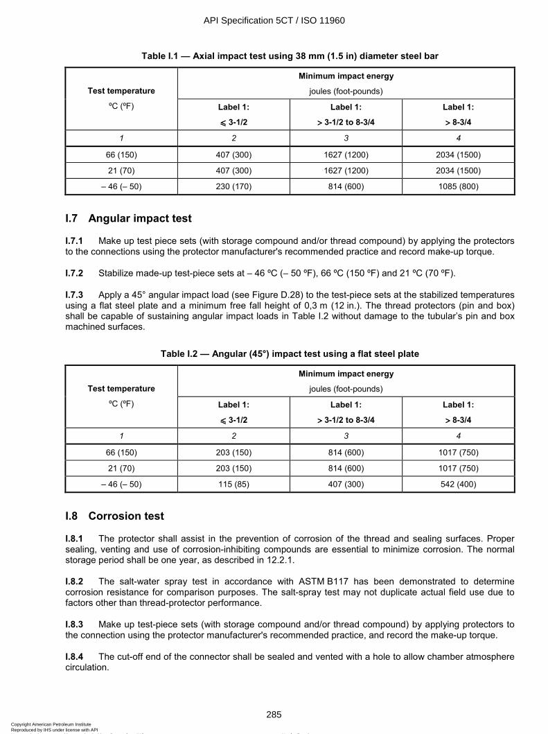
ISO 11960:2004(E)
© ISO 2004 – All rights reserved 285
Table I.1 — Axial impact test using 38 mm (1.5 in) diameter steel bar
Minimum impact energy
joules (foot-pounds) Test temperature
ºC (ºF) Label 1:
uuuu 3-1/2
Label 1:
>>>> 3-1/2 to 8-3/4
Label 1:
>>>> 8-3/4
1 2 3 4
66 (150) 407 (300) 1627 (1200) 2034 (1500)
21 (70) 407 (300) 1627 (1200) 2034 (1500)
– 46 (– 50) 230 (170) 814 (600) 1085 (800)
I.7 Angular impact test
I.7.1 Make up test piece sets (with storage compound and/or thread compound) by applying the protectors to the connections using the protector manufacturer's recommended practice and record make-up torque.
I.7.2 Stabilize made-up test-piece sets at – 46 ºC (– 50 ºF), 66 ºC (150 ºF) and 21 ºC (70 ºF).
I.7.3 Apply a 45° angular impact load (see Figure D.28) to the test-piece sets at the stabilized temperatures using a flat steel plate and a minimum free fall height of 0,3 m (12 in.). The thread protectors (pin and box) shall be capable of sustaining angular impact loads in Table I.2 without damage to the tubular’s pin and box machined surfaces.
Table I.2 — Angular (45°) impact test using a flat steel plate
Minimum impact energy
joules (foot-pounds) Test temperature
ºC (ºF) Label 1:
uuuu 3-1/2
Label 1:
>>>> 3-1/2 to 8-3/4
Label 1:
>>>> 8-3/4
1 2 3 4
66 (150) 203 (150) 814 (600) 1017 (750)
21 (70) 203 (150) 814 (600) 1017 (750)
– 46 (– 50) 115 (85) 407 (300) 542 (400)
I.8 Corrosion test
I.8.1 The protector shall assist in the prevention of corrosion of the thread and sealing surfaces. Proper sealing, venting and use of corrosion-inhibiting compounds are essential to minimize corrosion. The normal storage period shall be one year, as described in 12.2.1.
I.8.2 The salt-water spray test in accordance with ASTM B117 has been demonstrated to determine corrosion resistance for comparison purposes. The salt-spray test may not duplicate actual field use due to factors other than thread-protector performance.
I.8.3 Make up test-piece sets (with storage compound and/or thread compound) by applying protectors to the connection using the protector manufacturer's recommended practice, and record the make-up torque.
I.8.4 The cut-off end of the connector shall be sealed and vented with a hole to allow chamber atmosphere circulation.
API Specification 5CT / ISO 11960
285Copyright American Petroleum Institute Reproduced by IHS under license with API
Not for ResaleNo reproduction or networking permitted without license from IHS
--`,,,```-`-`,,`,,`,`,,`---
ISO 11960:2004(E)
286 © ISO 2004 – All rights reserved
I.8.5 Conduct a salt-spray test in accordance with ASTM B117 for a minimum of 1 000 h at a temperature of 35 ºC (95 ºF).
I.8.6 Orient the test-piece sets in the test chamber to simulate pipe rack storage.
I.8.7 The protectors shall be deemed to have passed the test if there is
no or slight corrosion damage in the seal and the perfect thread area, and
less than 10 % corrosion damage of the overall thread surface.
I.9 Stripping test (pin end only)
I.9.1 Make up test-piece sets (with storage compound and/or thread compound) by applying protectors to the connector using the protector manufacturer's recommended practice, and record the make-up torque.
I.9.2 Stabilize made-up test-piece sets at – 46 ºC (– 50 ºF), 66 ºC (150 ºF) and 21 ºC (70 ºF).
I.9.3 Conduct a stripping test in accordance with IADC/SPE 11396 on the pin protector (see Figure D.29) at the required stabilized temperatures and with an axial load equal to or greater than Fax:
Fax = 0,18 × wm
where
Fax is the force, expressed in kilonewtons;
wm is the linear mass of the pipe, expressed in kilograms per metre;
or
Fax = 60 × w
where
Fax is the force, expressed in pounds force;
w is the linear mass of the pipe, expressed in pounds per foot.
I.9.4 Remove the protectors and inspect for torn threads. Protector threads may show signs of stress but shall not be torn away.
I.10 Hookability (liftability) test
When a hookable (liftable) thread protector is required, the manufacturer shall demonstrate the hookability (liftability) of the design. The hookability (liftability) shall be evaluated on the basis of no damage to the pin-end or box-end of the connector. The type of hook used for the test shall be documented.
API Specification 5CT / ISO 11960
286Copyright American Petroleum Institute Reproduced by IHS under license with API
Not for ResaleNo reproduction or networking permitted without license from IHS
--`,,,```-`-`,,`,,`,`,,`---
ISO 11960:2004(E)
© ISO 2004 – All rights reserved 287
Annex J (informative)
Summary of Product Specification Level (PSL) requirements
J.1 General
J.1.1 This annex is provided for the convenience of the user of this specification and identifies the additional requirements when product is ordered to PSL-2 or PSL-3.
J.1.2 Requirements are given in the subclauses indicated in square brackets [ ] after each item.
J.2 PSL-2 requirements
J.2.1 All grades except H40
J.2.1.1 Mandatory CVN impact testing and requirements (according to SR 16) [H.6.2.1].
NOTE This is a PSL-1 requirement for Grades M65 and Q125.
J.2.1.2 No product to be susceptible to having material detach during make-up (appropriate processing or abrasive blasting [H.10 and H.12].
J.2.1.3 Seal-ring groove machining and tolerances [H.11].
J.2.1.4 Metallographic examination of the weld zone [H.15].
NOTE This is a PSL-1 requirement for Grades P110 and Q125, and there is no EW Grade L80 13CR, C90, or T95.
J.2.1.5 Wall thickness measurement (25 % coverage) [H.17.1].
J.2.1.6 Thread protectors shall be qualified to Annex I requirements [H.19].
J.2.1.7 Certification to SR 15 (with heat and lot traceability) [H.20].
J.2.1.8 Seal ring to be shipped separately [H.21].
J.2.2 Grades J55 and K55
J.2.2.1 Full-body heat treatment (after upsetting if applicable) [H.2.1].
J.2.2.2 Alternative test pressures for Label 1 larger than 9-5/8 [H.16].
J.2.2.3 NDE for longitudinal internal and external defects with a 12,5 % notch [H.18.1.1].
J.2.2.4 For K55 only: ultrasonic testing of the weld seam after hydrostatic test [H.18.2].
J.2.3 Grade M65
J.2.3.1 NDE for longitudinal and transverse, internal and external defects with a 10 % notch (no MPI) [H.18.1.2].
API Specification 5CT / ISO 11960
287Copyright American Petroleum Institute Reproduced by IHS under license with API
Not for ResaleNo reproduction or networking permitted without license from IHS
--`,,,```-`-`,,`,,`,`,,`---
ISO 11960:2004(E)
288 © ISO 2004 – All rights reserved
J.2.3.2 Ultrasonic testing of the weld seam after hydrostatic test [H.18.2].
J.2.4 Grades N80 Type 1 and N80Q
J.2.4.1 CVN impact shear area requirement of 75 % shear [H.6.1].
J.2.4.2 Tensile test frequency as for Grade L80 [H.13].
J.2.4.3 NDE for longitudinal and transverse, internal and external defects with a 10 % notch (no MPI) [H.18.1.2].
J.2.5 Grade L80 Type 1
J.2.5.1 CVN impact shear area requirement of 75 % shear [H.6.1].
J.2.5.2 Minimum martensite content of 90 % (based on a minimum Rockwell C-scale hardness for an as-quenched sample) [H.7.1].
J.2.5.3 NDE for longitudinal and transverse, internal and external defects with a 5 % notch, on pipe [H.18.1.3].
J.2.5.4 NDE for coupling stock [H.18.4].
J.2.6 Grade L80 13Cr
J.2.6.1 Inside surface preparation [H.8].
J.2.6.2 NDE for longitudinal and transverse, internal and external defects with a 5 % notch, on pipe [H.18.1.3].
J.2.6.3 NDE for coupling stock [H.18.4].
J.2.7 Grades C90 and T95
J.2.7.1 Hot-straightening requirement with a minimum temperature or cold-straightening followed by stress relief [H.3.1].
J.2.7.2 Type 1 chemical composition required [H.4.1].
J.2.7.3 CVN impact shear area requirement of 75 % shear [H.6.1].
J.2.7.4 NDE for coupling stock [H.18.4].
J.2.8 Grade C95
J.2.8.1 Hot-straightening requirement with a minimum temperature or cold-straightening followed by stress relief [H.3.2].
J.2.8.2 CVN impact shear area requirement of 75 % shear [H.6.1].
J.2.8.3 NDE for longitudinal and transverse, internal and external defects with a 5 % notch, on pipe [H.18.1.3].
J.2.8.4 NDE for coupling stock [H.18.4].
API Specification 5CT / ISO 11960
288Copyright American Petroleum Institute Reproduced by IHS under license with API
Not for ResaleNo reproduction or networking permitted without license from IHS
--`,,,```-`-`,,`,,`,`,,`---
ISO 11960:2004(E)
© ISO 2004 – All rights reserved 289
J.2.9 Grade P110
J.2.9.1 Hot-straightening requirement with a minimum temperature or cold-straightening followed by stress relief [H.3.2].
J.2.9.2 CVN impact shear area requirement of 75 % shear [H.6.1].
J.2.9.3 NDE for coupling stock [H.18.4].
J.2.10 Grade Q125
J.2.10.1 Type 1 chemical composition required [H.4.1].
J.2.10.2 CVN impact shear area requirement of 75 % shear [H.6.1].
J.2.10.3 Statistical impact testing according to SR 12 [H.6.2.2].
J.2.10.4 NDE for coupling stock [H.18.4].
J.3 PSL-3 requirements
J.3.1 General
In addition to those requirements for PSL-2, PSL-3 has further requirements as described in the following sub-clauses.
J.3.2 All Grades except H40 and N80 Type 1
J.3.2.1 Wall thickness measurement with 100 % coverage, report the minimum wall thickness [H.17.2].
J.3.2.2 Wet MPI of threaded ends required before make-up [H.18.3].
J.3.3 All Grades except Group 1
NDE for coupling stock [H.18.5].
J.3.4 Grades J55, K55 and M65
NDE for longitudinal and transverse, internal and external, defects with a 5 % notch (no MPI) [H.18.1.4].
J.3.5 Grades N80Q, L80 Type 1, C95 and P110
J.3.5.1 Surface hardness test of each pipe body, upset end and coupling [H.14.1].
J.3.5.2 NDE: mandatory ultrasonic test plus one other method [H.18.1.5].
J.3.6 Grade L80 13Cr
J.3.6.1 SSC test: using ANSI-NACE TM0177:1996, Method A, demonstrate a threshold stress of 80 % of the specified minimum yield stress in a test solution with pH 3,5 and a hydrogen sulfide partial pressure of 10 kPa (1.5 psi) [H.9.2].
J.3.6.2 NDE: mandatory ultrasonic test plus EMI for the outside surface [H.18.1.5].
API Specification 5CT / ISO 11960
289Copyright American Petroleum Institute Reproduced by IHS under license with API
Not for ResaleNo reproduction or networking permitted without license from IHS
--`,,,```-`-`,,`,,`,`,,`---
ISO 11960:2004(E)
290 © ISO 2004 – All rights reserved
J.3.7 Grades C90 and T95
J.3.7.1 Agreement on chemical composition [H.4.2].
J.3.7.2 Minimum martensite content of 95 % (based on a minimum Rockwell C-scale hardness for an as-quenched sample) [H.7.2].
J.3.7.3 SSC test: using ANSI-NACE TM0177:1996, Method A, test three pipes per heat at an applied stress of 90 % of the specified minimum yield stress [H.9.1].
J.3.7.4 Hardness test of both ends of each pipe [H.14.2].
J.3.8 Grade Q125
J.3.8.1 Maximum yield strength of 965 MPa (140 ksi) specified [H.5].
J.3.8.2 Surface hardness test of each pipe body, upset and coupling [H.14.1].
API Specification 5CT / ISO 11960
290Copyright American Petroleum Institute Reproduced by IHS under license with API
Not for ResaleNo reproduction or networking permitted without license from IHS
--`,,,```-`-`,,`,,`,`,,`---
ISO 11960:2004(E)
© ISO 2004 – All rights reserved 291
Bibliography
[1] Failure Analysis and Prevention, ASM Metals Handbook, Volume 11, 9th edition, 1986
[2] J.M. HODGE and M.A. OREHOSKI, Relationship between hardenability and percentage martensite in some low alloy steels. Trans. AIME, 167, 1946, pp. 627-642
[3] API Bull 5A2, Bulletin on Thread Compounds for Casing, Tubing, and Line Pipe, sixth edn, May 31, 1988
[4] API Spec 5CT, Specification for Casing and Tubing Seventh Edition; ISO 11960:2001; Supersedes Spec 5CT Metric/ISO 11960 Adoption
[5] National Bureau of Standards, Handbook 91, U.S. Department of Commerce, Experimental Statistics
[6] API RP 5A3, Recommended Practice On Thread Compounds For Casing, Tubing And Line Pipe
[7] API RP 5C1, Recommended Practice for Care and Use of Casing and Tubing
API Specification 5CT / ISO 11960
291Copyright American Petroleum Institute Reproduced by IHS under license with API
Not for ResaleNo reproduction or networking permitted without license from IHS
--`,,,```-`-`,,`,,`,`,,`---

Copyright American Petroleum Institute Reproduced by IHS under license with API
Not for ResaleNo reproduction or networking permitted without license from IHS
--`,,,```-`-`,,`,,`,`,,`---
Invoice To (❏ Check here if same as “Ship To”)
Name:
Title:
Company:
Department:
Address:
City: State/Province:
Zip/Postal Code: Country:
Telephone:
Fax:
E-Mail:
❏ Payment Enclosed ❏ P.O. No. (Enclose Copy)
❏ Charge My Global Account No.
❏ VISA ❏ MasterCard ❏ American Express ❏ Diners Club ❏ Discover
Credit Card No.:
Print Name (As It Appears on Card):
Expiration Date:
Signature:
Quantity Product Number Title Total
Subtotal
Applicable Sales Tax (see below)
Rush Shipping Fee (see below)
Shipping and Handling (see below)
Total (in U.S. Dollars)
★ To be placed on Standing Order for future editions of this publication,place a check mark in the SO column and sign here:
Pricing and availability subject to change without notice.
Date:
SO★ Unit Price
❏ API Member (Check if Yes)
Ship To (UPS will not deliver to a P.O. Box)
Name:
Title:
Company:
Department:
Address:
City: State/Province:
Zip/Postal Code: Country:
Telephone:
Fax:
E-Mail:
Mail Orders – Payment by check or money order in U.S. dollars is required except for established accounts. State and local taxes, $10 processing fee*, and 5% shipping must be added. Sendmail orders to: API Publications, Global Engineering Documents, 15 Inverness Way East, M/S C303B, Englewood, CO 80112-5776, USA.Purchase Orders – Purchase orders are accepted from established accounts. Invoice will include actual freight cost, a $10 processing fee*, plus state and local taxes.Telephone Orders – If ordering by telephone, a $10 processing fee* and actual freight costs will be added to the order.Sales Tax – All U.S. purchases must include applicable state and local sales tax. Customers claiming tax-exempt status must provide Global with a copy of their exemption certificate.Shipping (U.S. Orders) – Orders shipped within the U.S. are sent via traceable means. Most orders are shipped the same day. Subscription updates are sent by First-Class Mail. Other options,including next-day service, air service, and fax transmission are available at additional cost. Call 1-800-854-7179 for more information.Shipping (International Orders) – Standard international shipping is by air express courier service. Subscription updates are sent by World Mail. Normal delivery is 3-4 days from shipping date.Rush Shipping Fee – Next Day Delivery orders charge is $20 in addition to the carrier charges. Next Day Delivery orders must be placed by 2:00 p.m. MST to ensure overnight delivery.Returns – All returns must be pre-approved by calling Global’s Customer Service Department at 1-800-624-3974 for information and assistance. There may be a 15% restocking fee. Special orderitems, electronic documents, and age-dated materials are non-returnable.*Minimum Order – There is a $50 minimum for all orders containing hardcopy documents. The $50 minimum applies to the order subtotal including the $10 processing fee, excluding anyapplicable taxes and freight charges. If the total cost of the documents on the order plus the $10 processing fee is less than $50, the processing fee will be increased to bring the order amountup to the $50 minimum. This processing fee will be applied before any applicable deposit account, quantity or member discounts have been applied. There is no minimum for orders containing onlyelectronically delivered documents.
Effective January 1, 2005.API Members receive a 30% discount where applicable.The member discount does not apply to purchases made for the purpose of resale or for incorporation into commercial products, training courses, workshops, or othercommercial enterprises.
Available through Global Engineering Documents:Phone Orders: 1-800-854-7179 (Toll-free in the U.S. and Canada)
303-397-7956 (Local and International)Fax Orders: 303-397-2740Online Orders: www.global.ihs.com
®APIAmerican Petroleum Institute2005 Publications Order Form
Copyright American Petroleum Institute Reproduced by IHS under license with API
Not for ResaleNo reproduction or networking permitted without license from IHS
--`,,,```-`-`,,`,,`,`,,`---
There’s more where this came from.The American Petroleum Institute provides additional resources and programs to the oil and natural gas industry which are based on API® Standards. For moreinformation, contact:
• API Monogram® Licensing Program Phone: 202-962-4791Fax: 202-682-8070
• American Petroleum Institute Quality Registrar Phone: 202-962-4791(APIQR®) Fax: 202-682-8070
• API Spec Q1® Registration Phone: 202-962-4791Fax: 202-682-8070
• API Perforator Design Registration Phone: 202-962-4791Fax: 202-682-8070
• API ISO/TS 29001 Registration Phone: 202-962-4791Fax: 202-682-8070
• API Training Provider Certification Program Phone: 202-682-8490Fax: 202-682-8070
• Individual Certification Programs Phone: 202-682-8064Fax: 202-682-8348
• Engine Oil Licensing and Certification System (EOLCS) Phone: 202-682-8516Fax: 202-962-4739
• API PetroTEAM™ (Training, Education and Meetings) Phone: 202-682-8195Fax: 202-682-8222
Check out the API Publications, Programs, and Services Catalog online at www.api.org.
Helping You Get The Job Done Right.®
Copyright American Petroleum Institute Reproduced by IHS under license with API
Not for ResaleNo reproduction or networking permitted without license from IHS
--`,,,```-`-`,,`,,`,`,,`---

Copyright American Petroleum Institute Reproduced by IHS under license with API
Not for ResaleNo reproduction or networking permitted without license from IHS
--`,,,```-`-`,,`,,`,`,,`---

Additional copies are available through Global Engineering Documents at (800) 854-7179 or (303) 397-7956
Information about API Publications, Programs and Services is available on the World Wide Web at http://www.api.org
Product No: GX5CT08
Copyright American Petroleum Institute Reproduced by IHS under license with API
Not for ResaleNo reproduction or networking permitted without license from IHS
--`,,,```-`-`,,`,,`,`,,`---