api specification 16rcd ballot draft - my...
TRANSCRIPT
Ballot Draft
Specification for Drill Through Equipment – Rotating Control Devices 1
DRAFT Specification for Drill Through Equipment – Rotating Control Devices API Specification 16RCD (Note: Patterned on API Specification 16A – reflects underbalanced drilling operating environment and requirements)
API 16A UBO Task Group Revision: Draft-3.4 April 26, 2004
Ballot Draft
2 SPECIFICATION 16RCD
FOREWORD This publication is under jurisdiction of the API Subcommittee on Drilling Well Control Systems. This specification was formulated to serve as an aid to procurement of standardized equipment and materials as well as provide instructions to designers and manufacturers of marine drilling riser equipment. It identifies requirements for design, materials, processing and testing of standardized equipment. This standard shall become effective on the date printed on the cover but may be used voluntarily from the date of distribution. This publication includes use of the verbs "shall" and "should" whichever is deemed most applicable for the specific situation. For the purpose of this publication, the following definitions are applicable: Shall. Denotes a minimum requirement in order to conform to the specification. Should. Denotes a recommendation or that which is advised but not required in order to conform to the specification. Changes in the uses of these verbs are not to be made without risk of changing intent of specifications set forth herein. Suggested revisions are invited and should be submitted to the director of the Exploration and Production Department, American Petroleum Institute, 1220 L Street, Northwest, Washington, DC 20005-4070.
Ballot Draft
Specification for Drill Through Equipment – Rotating Control Devices 3
Table of Contents
1 Scope................................................................................................................................................... 5 1.1 Purpose........................................................................................................................................ 5 1.2 Applications ................................................................................................................................ 5 1.3 Product Specification .................................................................................................................. 5 1.4 Units and Dimensioning ............................................................................................................. 5 1.5 Metric Conversions..................................................................................................................... 5 1.6 Appendices.................................................................................................................................. 5
2 Referenced Standards.......................................................................................................................... 5 2.1 General ........................................................................................................................................ 5 2.2 Requirements .............................................................................................................................. 5 2.3 Alternate Standards..................................................................................................................... 5
3 Definitions /Abbreviations and Descriptions.................................................................................... 11 3.1 Definitions................................................................................................................................. 11 3.2 Abbreviations and Descriptions................................................................................................ 14
4 Design Requirements ........................................................................................................................ 15 4.1 Size Designation ....................................................................................................................... 15 4.2 Service Conditions .................................................................................................................... 15 4.3 Equipment-Specific Design Requirements ............................................................................... 15 4.4 Design Methods ........................................................................................................................ 19 4.5 Design Verification Testing...................................................................................................... 20 4.6 Documentation.......................................................................................................................... 20 4.7 Operational Characteristics Tests ............................................................................................. 20 4.8 Design Temperature Verification Testing for Non-Metallic Sealing Materials and Molded Sealing Assemblies ............................................................................................................................... 25 4.9 Operating Manual Requirements .............................................................................................. 25
5 Material Requirements...................................................................................................................... 26 5.1 General ...................................................................................................................................... 26 5.2 Written Specifications............................................................................................................... 26 5.3 Pressure-Containing Members.................................................................................................. 26
6 Welding Requirements...................................................................................................................... 31 6.1 General ...................................................................................................................................... 31 6.2 Weldment Design and Configuration ....................................................................................... 31 6.3 Welding Controls ...................................................................................................................... 33 6.4 Welding Procedure and Performance Qualifications................................................................ 34 6.5 Other Requirements .................................................................................................................. 35
7 Quality Control Requirements .......................................................................................................... 38 7.1 General ...................................................................................................................................... 38 7.2 Measuring and Testing Equipment ........................................................................................... 38 7.3 Quality Control Personnel Qualifications................................................................................. 39 7.4 Quality Control Requirements for Equipment and Parts .......................................................... 39 7.5 Quality Control Requirements for Specific Equipment and Parts ............................................ 39 7.6 7.6 Quality Control Records Requirements ............................................................................. 47
8 Marking Requirements...................................................................................................................... 48 8.1 General ...................................................................................................................................... 48
API 16A UBO Task Group Revision: Draft-3.4 April 26, 2004
Ballot Draft
4 SPECIFICATION 16RCD
8.2 Types of Identification Stamping.............................................................................................. 49 8.3 Specific Codification Requirements of Equipment .................................................................. 49
9 Storing and Shipping......................................................................................................................... 51 9.1 Storing for Periods of Greater than 30 Days............................................................................. 51 9.2 Shipping .................................................................................................................................... 51
APPENDIX A - Metric Conversions and Fraction-to-Decimal Equivalents............................................ 53 APPENDIX B - Operational Characteristics Test Procedures. ................................................................ 55 APPENDIX C—Design Temperature Verification Test Procedures. ...................................................... 57 APPENDIX D—Recommended Practice for Heat-treating Equipment Qualifications ........................... 60 APPENDIX E—Typical Weld Groove Designs....................................................................................... 62 APPENDIX F— Purchasing Guidelines .................................................................................................. 65 APPENDIX G—Failure Reporting........................................................................................................... 66 APPENDIX H—Referenced Standards.....................................................Error! Bookmark not defined. Figures Figure 1 –Typical Surface Stack illustrating an Active Rotating Control Devices .................................... 8 Figure 2–Typical Surface Stack illustrating a Passive Rotating Control Device ....................................... 9 Figure 3 –Typical Surface Stack illustrating a Hybrid Rotating Control Device ..................................... 10 Figure 4 - Equivalent Round Models........................................................................................................ 32 Figure 5 - Welding Procedure Qualification Rockwell Hardness Test Locations.................................... 35 Figure 6 - Welding Procedure Qualification Vickers Hardness Test Locations....................................... 36 Figure D 1 - Thermocouple Locations...................................................................................................... 61 Tables Table 1 - Temperature Ratings for Metallic Materials ............................................................................. 15 Table 2 - Pressure Ratings and Size Ranges of API Specification 6A Flange Connections .................... 16 Table 3 - Required Operational Characteristics Tests And Acceptable Scaling Practices ....................... 21 Table 4 - Pressure Containing Member Material Property Requirements............................................... 27 Table 5 - API Material Applications for Pressure Containing Members.................................................. 27 Table 6 - Steel Composition Limits (Wt%) for Pressure-Containing Members....................................... 28 Table 7 - Alloying Element Maximum Tolerance Range Requirements (Wt%)...................................... 28 Table 8 - Acceptance Criteria Charpy V-Notch Impact Requirements .................................................... 29 Table 9 - Elastomer Compound Marking Code........................................................................................ 50 Table 10 - Marking Requirements and Locations..................................................................................... 52
Ballot Draft
SPECIFICATION FOR DRILL THROUGH EQUIPMENT – ROTATING CONTROL DEVICES 5
1 SCOPE 1.1 PURPOSE This specification is formulated to provide for the availability of safe and functionally interchangeable Rotating Control Devices (RCDs) utilized for drilling for oil and gas. Technical content provides requirements for design, performance, materials, tests and inspection, welding, marking, handling, storing, and shipping. This specification does not apply to field use or field-testing of RCDs. Critical components are those parts having requirements specified in this document.
1.2 APPLICATIONS 1.2.1 Equipment Specific equipment covered by this specification is listed as follows:
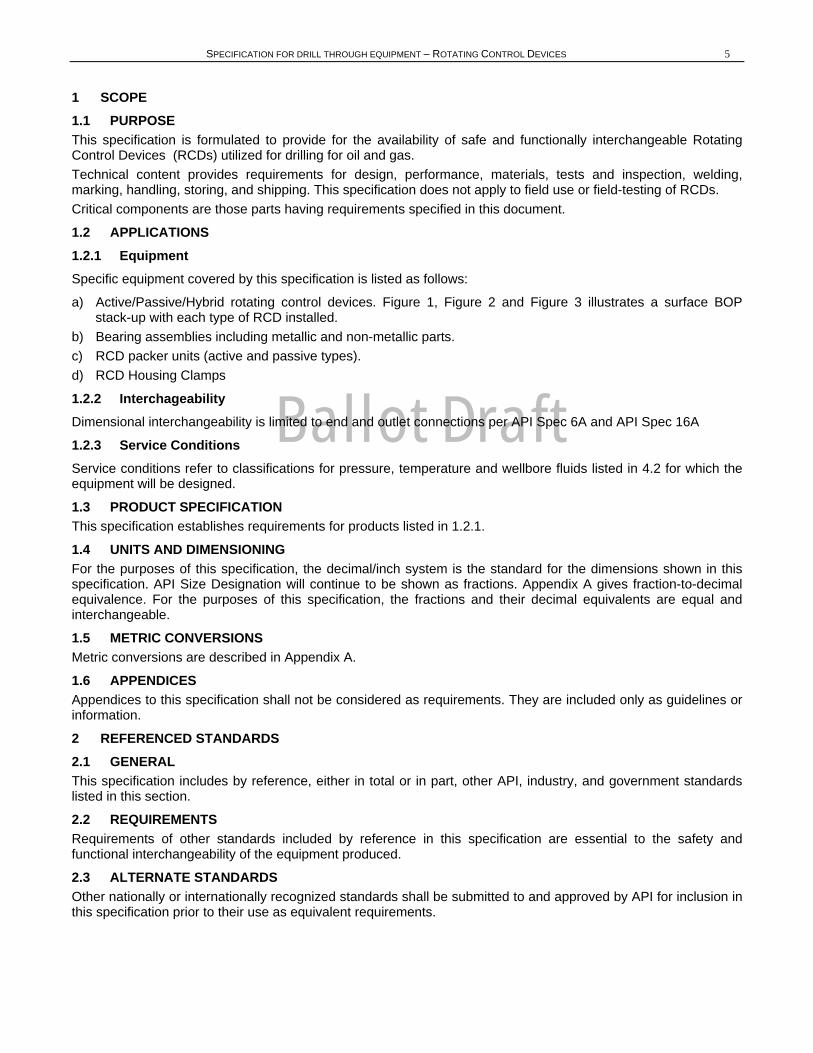
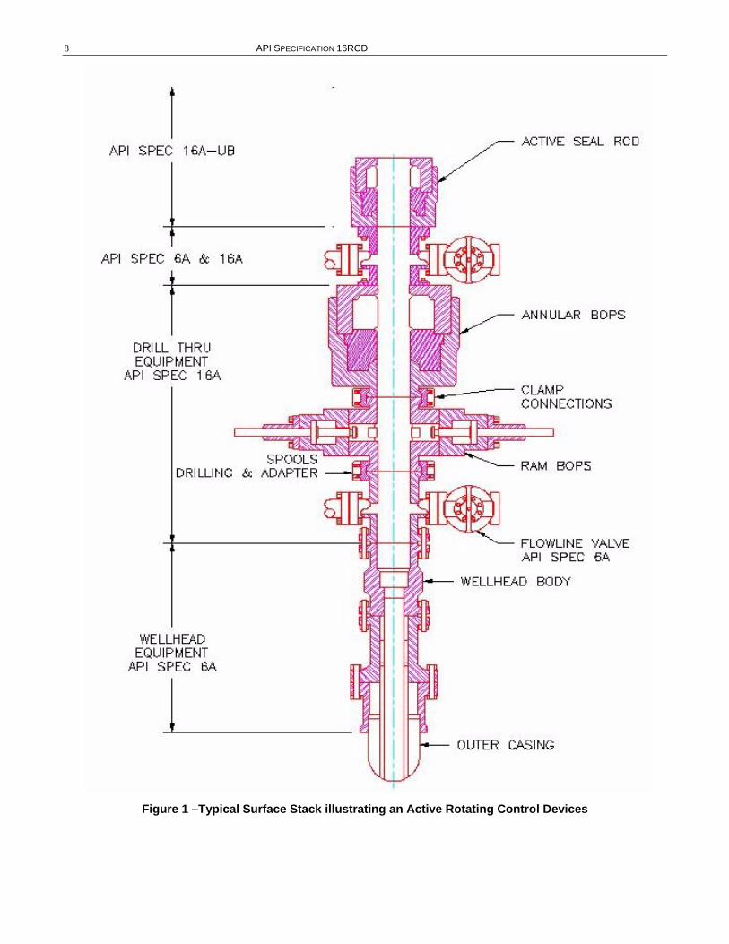
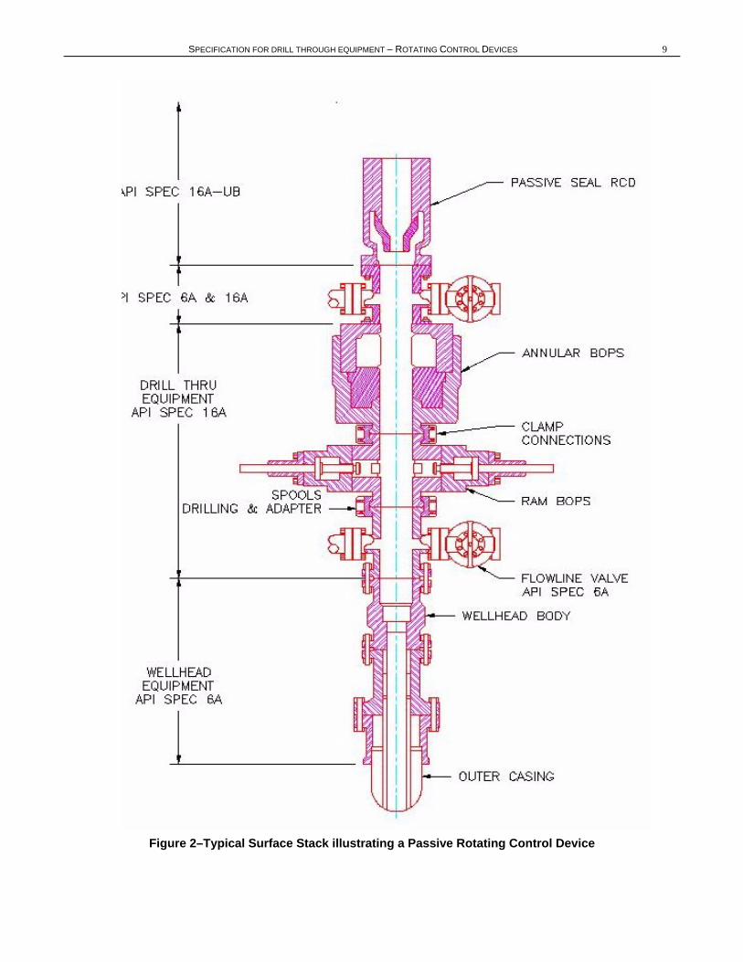
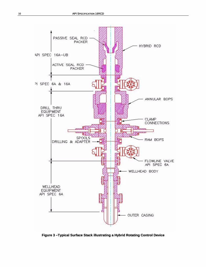
a) Active/Passive/Hybrid rotating control devices. Figure 1, Figure 2 and Figure 3 illustrates a surface BOP stack-up with each type of RCD installed.
b) Bearing assemblies including metallic and non-metallic parts. c) RCD packer units (active and passive types). d) RCD Housing Clamps
1.2.2 Interchageability Dimensional interchangeability is limited to end and outlet connections per API Spec 6A and API Spec 16A
1.2.3 Service Conditions Service conditions refer to classifications for pressure, temperature and wellbore fluids listed in 4.2 for which the equipment will be designed.
1.3 PRODUCT SPECIFICATION This specification establishes requirements for products listed in 1.2.1.
1.4 UNITS AND DIMENSIONING For the purposes of this specification, the decimal/inch system is the standard for the dimensions shown in this specification. API Size Designation will continue to be shown as fractions. Appendix A gives fraction-to-decimal equivalence. For the purposes of this specification, the fractions and their decimal equivalents are equal and interchangeable.
1.5 METRIC CONVERSIONS Metric conversions are described in Appendix A.
1.6 APPENDICES Appendices to this specification shall not be considered as requirements. They are included only as guidelines or information.
2 REFERENCED STANDARDS 2.1 GENERAL This specification includes by reference, either in total or in part, other API, industry, and government standards listed in this section.
2.2 REQUIREMENTS Requirements of other standards included by reference in this specification are essential to the safety and functional interchangeability of the equipment produced.
2.3 ALTERNATE STANDARDS Other nationally or internationally recognized standards shall be submitted to and approved by API for inclusion in this specification prior to their use as equivalent requirements.
Ballot Draft
6 API SPECIFICATION 16RCD
API1
Spec 5CT Specification for Casing and Tubing Spec 5D Specification for Drill Pipe Spec 6A Specification for Wellhead and Christmas Equipment Spec 16A Specification for Drill Through Equipment Bull 6AF2 Capabilities of API Flanges under Combinations of Loads
ANSI ASQC Z1.4 Sampling Procedures for Tables for Inspection by Attributes
ASME2
Boiler and Pressure Vessel Code, Section V, Nondestructive Testing,\ Article 5, UT Examination Methods for Materials and Fabrication Boiler and Pressure Vessel Code, Section VIII, Division 1 Appendix 4: Rounded Indication Charts Acceptance Standard for Radiographically Determined Rounded Indications in
Welds Boiler and Pressure Vessel Code, Section VIII, Division 2: Pressure Vessel—Alternate Rules Appendix 4: Design Based on Stress Analysis Appendix 6: Experimental Stress Analysis
ASNT3
SNT-TC-1A Personnel Qualification and Certification in Nondestructive Testing, 1984 or latest Edition ASTM
A193 Specification for Alloy Steel and Stainless Steel Bolting Materials for High Temperature Service A320 Specification for Alloy Steel Bolting Materials for Low Temperature Service A370 Test Methods and Definitions for Mechanical Testing of Steel Products A453 Specification for Bolting Materials, High Temperature, 50 to 120 ksi Yield Strength, with Expansion Coefficients
Comparable to Austenitic Steels D395 Standard Test Methods for Rubber Property—Compression Set D412 Test Methods for Vulcanized Rubber, Thermoplastic Rubbers and Thermoplastic Elastomers D471 Standard Test Methods for Rubber Property—Effect of Liquids
D475 Specification for Pure Para Red Toner Pigment D569 Method for Measuring the Flow Properties of Thermoplastic Molding Materials D575 Test Methods for Rubber Properties in Compression D1414 Test Methods for Rubber O-Rings D1415 Test Method for Rubber Property—International Hardness D1418 Practice for Rubber and Rubber Latices—Nomenclature D2084 Test Method for Rubber Property—Vulcanization Characteristics Using Oscillating Disk Cure Meter D2240 Test Method for Rubber Property—Durometer Hardness E10 Test Method for Brinell Hardness of Metallic Materials E18 Test Methods for Rockwell Hardness and Rockwell Superficial Hardness of Metallic Materials E30 Test Method for Chemical Analysis of Steel, Cast Iron, Open-Hearth Iron, and Wrought Iron E92 Test Method for Vickers Hardness of Metallic Materials E94 Guide for Radiographic Testing E140 Hardness Conversion Tables for Metals E165 Practice for Liquid Penetrant Examination E709 Practice for Magnetic Particle Examination E747 Guide for Controlling Quality of Radiographic Examination Using Wire Pentrameters
Ballot Draft
SPECIFICATION FOR DRILL THROUGH EQUIPMENT – ROTATING CONTROL DEVICES 7
MIL-STD4
MIL-STD-120 Gage Inspection MIL-STD-105D Sampling Procedures and Tables for Inspection Attributes
NACE5
MR0175 Sulfide Stress Cracking Resistant Metallic Materials for Oilfield Equipment
1American National Standards Institute, 11 West 42nd Street, New York, New York 10036 2American Society for Mechanical Engineers, 345 East 47th Street New York, New York 10017 3American Society for Nondestructive Testing, Inc., 1711 Arlington Lane, P.O. Box 28518, Columbus, Ohio 43228-0518 4US Government Printing Office, Washington, DC 5National Association of Corrosion Engineers, P.O. Box 218340, Houston, Texas 77218
Ballot Draft
8 API SPECIFICATION 16RCD
Figure 1 –Typical Surface Stack illustrating an Active Rotating Control Devices
Ballot Draft
SPECIFICATION FOR DRILL THROUGH EQUIPMENT – ROTATING CONTROL DEVICES 9
Figure 2–Typical Surface Stack illustrating a Passive Rotating Control Device
Ballot Draft
10 API SPECIFICATION 16RCD 10 API SPECIFICATION 16RCD
Figure 3 –Typical Surface Stack illustrating a Hybrid Rotating Control Device Figure 3 –Typical Surface Stack illustrating a Hybrid Rotating Control Device
Ballot Draft
SPECIFICATION FOR DRILL THROUGH EQUIPMENT – RCDS 11 3 DEFINITIONS /ABBREVIATIONS AND DESCRIPTIONS 3.1 DEFINITIONS 3.1.1. acceptance criteria: Defined limits placed on characteristics of materials, products, or services.
3.1.2. active seal relaxed diameter: The inside diameter through the active packing element when in the fully open condition (no hydraulic closing pressure applied and after closing to manufacturers minimum specified diameter).
3.1.3. API Monogram: A registered mark of the American Petroleum Institute.
3.1.4. body: Any portion of equipment between end connections, with or without internal parts, which contains wellbore pressure.
3.1.5. bolting, closure: Threaded fasteners used to assemble API Specification 16RCD pressure-containing parts other than end and outlet connections.
3.1.6. bolting: Threaded fasteners used to join end or outlet connections.
3.1.7. bore through the bearing: The minimum inside diameter through the bearing assembly.
3.1.8. bore through the body: The minimum inside diameter through the RCD body including the bottom connection.
3.1.9. calibration: Comparison and adjustment to a standard of known accuracy.
3.1.10. casting: (1) An object at or near finished shape obtained by solidification of a substance in a mold. (2) Pouring molten metal into a mold to produce an object of desired shape.
3.1.11. chemical analysis: Determination of the chemical composition of material.
3.1.12. clamp, RCD Housing: A device used to fasten and lock mating RCD body components.
3.1.13. clamp: A device with internal angled shoulders used to fasten mating hubs.
3.1.14. clamping load: The axial load applied to the clamp hubs by the clamp due to hydraulic force or bolt tightening.
3.1.15. conformance (conform): Compliance with specified requirements in every detail.
3.1.16. connection, API: Flanges, hubs, and studded connections manufactured in accordance with API specification including dimensional requirements.
3.1.17. connection, blind: An end or outlet connection with no center bore, used to completely close off a connection.
3.1.18. connection, end: Flanges (studded or open face), hub connections or Other End Connections which are used to join together equipment and are integral to the equipment.
3.1.19. connection, loose: Flanges (studded or open face), hub connections, or Other End Connections which are used to join together equipment but are not integral to the equipment.
3.1.20. connection, other end (O.E.C.): Connections which are not specified in an API dimensional specification, including API flanges and hubs with non-API gasket preparations and manufacturer’s proprietary connections.
3.1.21. connections, studded: Connections in which thread-anchored studs are screwed into tapped holes.
3.1.22. CSO: Complete shut-off of wellbore with out tubular in wellbore.
3.1.23. data acquisition system: A system for storing and/or providing permanent copies of test information, such as: strip chart recorders, circular chart recorders, or computer systems.
3.1.24. date of manufacture: The date of manufacturer’s final acceptance of finished equipment.
3.1.25. dynamic pressure rating: The maximum pressure rating including rotation of the drill string and packing element, while drilling.
Ballot Draft
12 API SPECIFICATION 16RCD
3.1.26. equipment: Any single completed unit that can be used for its intended purpose without further processing or assembly.
3.1.27. examination, visual: Examination of parts and equipment for visible defects in material and workmanship.
3.1.28. examination, volumetric nondestructive: Examination for internal material defects by radiography, acoustic emission, or ultrasonic testing.
3.1.29. flange: A protruding rim, with holes to accept bolts and having a sealing mechanism, used to join pressure containing equipment together by bolting one flange to another.
3.1.30. forging: (1) Plastically deforming metal, usually hot, into desired shapes with compressive force, with open or closed dies. (2) A shaped metal part formed by the forging method.
3.1.31. gasket retaining load: That portion of the clamping load required to offset the separating force the gasket exerts on the mating parts when pressurized.
3.1.32. gasket seating load: That portion of the clamping load required to seat the gasket and bring the mating RCD and RCD bearing assembly faces into contact.
3.1.33. heat (cast lot): Material originating from a final melt. For remelted alloys, a heat shall be defined as the raw material originating from a single remelted ingot.
3.1.34. heat affected zone (HAZ): That portion of the base metal which has not been melted, but whose mechanical properties or microstructure has been altered by the heat of welding or cutting.
3.1.35. heat treatment (heat-treating): Alternate steps of controlled heating and cooling of materials for the purpose of changing physical or mechanical properties.
3.1.36. heat treatment load: That material moved as a batch through one heat treatment cycle.
3.1.37. hot working: Deforming metal plastically at a temperature above the recrystallization temperature.
3.1.38. hub: Protruding rim with an external angled shoulder and a sealing mechanism used to join pressure-containing equipment.
3.1.39. hydraulic operating system rated working pressure - The maximum hydraulic pressure at which the equipment is designed to operate.
3.1.40. hydraulic operating system recommended operating pressure - The manufacturers recommended operating pressure.
3.1.41. indications, linear: An indication in liquid penetrant or magnetic particle examination whose length is equal to or greater than 3 times its width.
3.1.42. indications, relevant: Any indication in liquid penetrant or magnetic particle examination with a major dimension over 0.062 inch.
3.1.43. indications, rounded: Any indication in liquid penetrant or magnetic particle examination that is approximately circular or elliptical with its length less than 3 times its width.
3.1.44. indications: Visual signs of cracks, pits, or other abnormalities found during liquid penetrant and magnetic particle examination.
3.1.45. integral: Parts which are joined by the forging, casting, or welding process.
3.1.46. leakage: Visible passage of the pressurized fluid from the inside to the outside of the pressure containment area of the equipment being tested.
3.1.47. packing element: sealing element between the rotating control device and the drill string.
3.1.48. part: An individual piece used in the assembly of a single equipment unit.
3.1.49. personnel, qualified: Individuals with characteristics or abilities gained through training, experience, or both, as measured against the manufacturer’s established requirements.
3.1.50. post weld heat treatment: Any heat treatment subsequent to welding, including stress relief.
Ballot Draft
SPECIFICATION FOR DRILL THROUGH EQUIPMENT – ROTATING CONTROL DEVICES 13
3.1.51. pressure end load: The axial load resulting from internal pressure applied to the area defined by the maximum seal diameter.
3.1.52. pressure vessel quality: Metallic material the integrity of which is such that it can be used to safely contain pressure without risk of leakage or rupture.
3.1.53. pressure-containing part(s) or member(s): Those parts exposed to wellbore fluids whose failure to function as intended would result in a release of wellbore fluid to the environment, e.g., bodies, bearing assemblies.
3.1.54. pressure-controlling part(s) or member(s): Those parts intended to control or regulate the movement of wellbore fluids, e.g., packing elements, seats with a pressure-containing member or part(s).
3.1.55. pressure-retaining part(s) or member(s): Those parts not exposed to wellbore fluids whose failure to function as intended would result in a release of wellbore fluid to the environment, e.g., closure bolts and RCD Housing clamps.
3.1.56. product family: A model or type of specific equipment listed in 1.2.1.
3.1.57. rated working pressure: The maximum internal pressure that the equipment is designed to contain and/or control. For a RCD there is no designated rated working pressure since the maximum internal pressure that the equipment is designed to contain and/or control depends on the operation: dynamic – pipe rotating, stripping – pipe reciprocating or tripped but not rotating and static – no pipe movement.
3.1.58. records: Retrievable information. 3.1.59. relevant: See indications, relevant.
3.1.60. ring grooves, corrosion resistant: Ring grooves lined with metal resistant to metal-loss corrosion.
3.1.61. rotating control device (RCD): A drill through device with a rotating seal that contacts and seals against the drill string (drill pipe, casing, kelly etc.) for the purpose of controlling the pressure or fluid flow to surface.
3.1.62. rotating speed rating: The maximum rotating speed specified at a given pressure for a specific pipe size as defined by the manufacturer.
3.1.63. serialization: Assignment of a unique code to individual parts and/or pieces of equipment to maintain records.
3.1.64. special processes: Operations which convert or affect material properties.
3.1.65. stabilized (pressure testing): When the initial pressure decline rate decreases to within the manufacturer’s specified rate. This pressure decline can be caused by such things as changes in temperature, setting of elastomer seals or compression of trapped air in the equipment being tested.
3.1.66. stabilized (temperature testing): When the initial temperature fluctuations decrease to within the manufacturer’s specified range. This temperature fluctuation can be caused by such things as mixing of different temperature fluids, convection, or conduction.
3.1.67. static pressure rating: The maximum pressure that the equipment is designed to control with no pipe movement.
3.1.68. stress relief: Controlled heating of material to a predetermined temperature for the purpose of reducing any residual stresses.
3.1.69. stripping pressure rating: The maximum pressure when reciprocating or tripping but not rotating the drill string for a specific packer model.
3.1.70. structure, wrought: One that contains no cast dendritic structure.
3.1.71. surface finish: The measurement of the average roughness (RMS) of a surface. All of the surface finishes given within this specification are to be considered maximums.
3.1.72. traceability, job lot: The ability for parts to be identified as originating from a job lot which identifies the included heat(s).
3.1.73. trepanned: To produce a hole through a part by boring a narrow band or groove around the circumference of the hole and removing the solid central core of material.
Ballot Draft
14 API SPECIFICATION 16RCD
3.1.74. weld groove: An area between two metals to be joined that has been prepared to receive weld filler metal.
3.1.75. weld joint: A description of the way components are fitted together in order to facilitate joining by welding.
3.1.76. weld, fabrication: A weld joining two or more parts.
3.1.77. weld, full penetration: A weld which extends throughout the complete wall section of the parts joined.
3.1.78. weld, major repair: Welds that are greater than 25 percent of the original wall thickness or one inch, whichever is less.
3.1.79. weld, non pressure containing: A weld the failure of which will not reduce the pressure-containing integrity of the component.
3.1.80. weld, pressure containing: A weld, the failure of which will reduce the pressure-containing integrity of the component.
3.1.81. welding: The fusion of materials, with or without the addition of filler materials.
3.1.82. yield strength: The stress level measured at room temperature, expressed in pounds per square inch of loaded area, at which material plastically deforms and will not return to its original dimensions when the load is released. All yield strengths specified in this standard shall be considered as being the 0.2 percent yield offset strength per ASTM A370.
3.2 ABBREVIATIONS AND DESCRIPTIONS AE Acoustic Emissions
ANSI American National Standards Institute
API American Petroleum Institute
ASME American Society of Mechanical Engineers
ASNT American Society for Nondestructive Testing
ASTM American Society for Testing and Materials
AWS American Welding Society
CRA Corrosion Resistant Alloy
ER Equivalent Round
HAZ Heat Affected Zone
I.D. Inside Diameter
LP Liquid Penetrant
MP Magnetic Particle
MPD Managed Pressure Drilling
NACE National Association of Corrosion Engineers
NDE Nondestructive Examination
O.D. Outside Diameter
O.E.C. Other End Connection
PDC Product Description Code
PQR Procedure Qualification Record
Ballot Draft
SPECIFICATION FOR DRILL THROUGH EQUIPMENT – ROTATING CONTROL DEVICES 15
QTC Qualification Test Coupons
RCD Rotating Control Device
WPS Welding Procedure Specifications
4 DESIGN REQUIREMENTS 4.1 SIZE DESIGNATION The size designation of equipment within the scope of this specification shall be in accordance with 4.3.
4.2 SERVICE CONDITIONS 4.2.1 Pressure Ratings The static pressure rating, the dynamic pressure rating and the stripping pressure rating shall be specified by the manufacturer and validated by this specification. All pressure ratings are for new packing elements and shall not exceed the pressure rating of the lowest rated connection seeing well bore pressure.
4.2.2 Temperature Ratings Minimum temperature is the lowest ambient temperature to which the equipment may be subjected.
Maximum temperature is the highest temperature of the fluid, which may flow through the equipment.
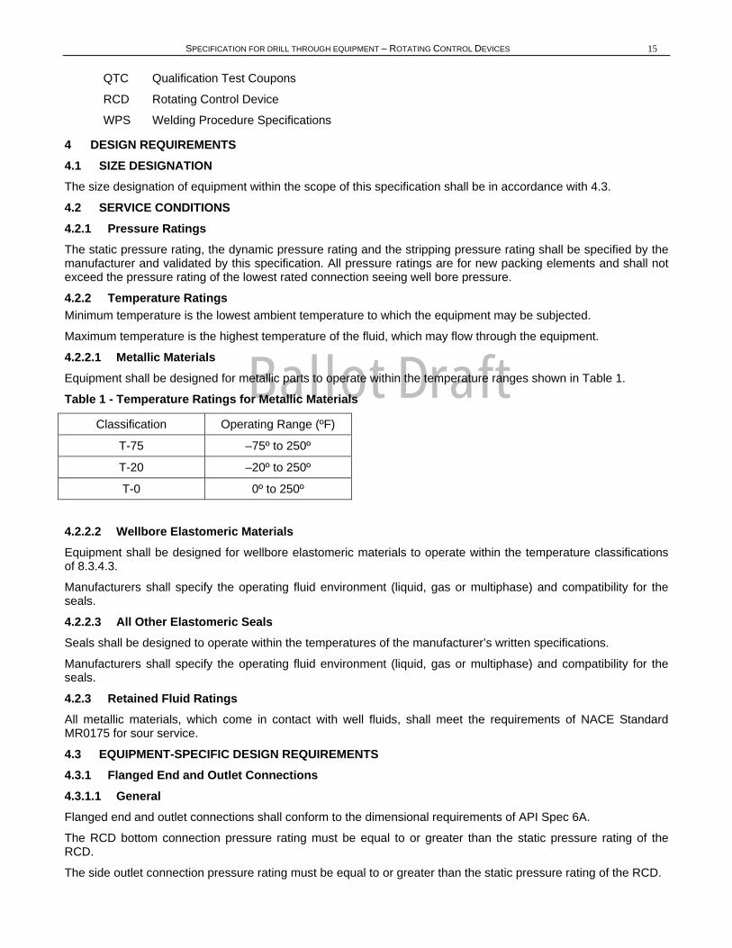
4.2.2.1 Metallic Materials Equipment shall be designed for metallic parts to operate within the temperature ranges shown in Table 1.
Table 1 - Temperature Ratings for Metallic Materials
Classification Operating Range (ºF)
T-75 –75º to 250º
T-20 –20º to 250º
T-0 0º to 250º
4.2.2.2 Wellbore Elastomeric Materials Equipment shall be designed for wellbore elastomeric materials to operate within the temperature classifications of 8.3.4.3.
Manufacturers shall specify the operating fluid environment (liquid, gas or multiphase) and compatibility for the seals.
4.2.2.3 All Other Elastomeric Seals Seals shall be designed to operate within the temperatures of the manufacturer’s written specifications.
Manufacturers shall specify the operating fluid environment (liquid, gas or multiphase) and compatibility for the seals.
4.2.3 Retained Fluid Ratings All metallic materials, which come in contact with well fluids, shall meet the requirements of NACE Standard MR0175 for sour service.
4.3 EQUIPMENT-SPECIFIC DESIGN REQUIREMENTS 4.3.1 Flanged End and Outlet Connections 4.3.1.1 General Flanged end and outlet connections shall conform to the dimensional requirements of API Spec 6A.
The RCD bottom connection pressure rating must be equal to or greater than the static pressure rating of the RCD.
The side outlet connection pressure rating must be equal to or greater than the static pressure rating of the RCD.
Ballot Draft
16 API SPECIFICATION 16RCD
4.3.1.1.1 6B and 6BX flange connections may be used as integral connections.
4.3.1.1.2 6B and 6BX flanges integral to RCDs shall not contain test connections.
4.3.1.1.3 The manufacturer shall document the load/capacity for the flanged end and outlet connections using the same format as used for API flanges in API Bulletin 6AF2. This format relates pressure to allowable bending moment for various tensions. The manufacturer shall state which part of the connection contains the stress limitations that form the basis for the graphs. Analytical design methods shall conform to 4.4.
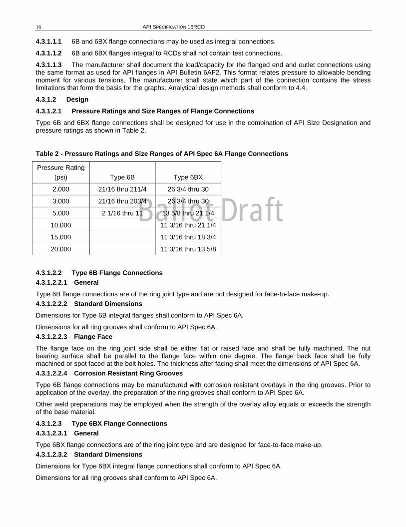
4.3.1.2 Design 4.3.1.2.1 Pressure Ratings and Size Ranges of Flange Connections Type 6B and 6BX flange connections shall be designed for use in the combination of API Size Designation and pressure ratings as shown in Table 2.
Table 2 - Pressure Ratings and Size Ranges of API Spec 6A Flange Connections
Pressure Rating (psi)
Type 6B
Type 6BX
2,000 21/16 thru 211/4 26 3/4 thru 30
3,000 21/16 thru 203/4 26 3/4 thru 30
5,000 2 1/16 thru 11 13 5/8 thru 21 1/4
10,000 11 3/16 thru 21 1/4
15,000 11 3/16 thru 18 3/4
20,000 11 3/16 thru 13 5/8
4.3.1.2.2 Type 6B Flange Connections 4.3.1.2.2.1 General Type 6B flange connections are of the ring joint type and are not designed for face-to-face make-up. 4.3.1.2.2.2 Standard Dimensions Dimensions for Type 6B integral flanges shall conform to API Spec 6A.
Dimensions for all ring grooves shall conform to API Spec 6A. 4.3.1.2.2.3 Flange Face The flange face on the ring joint side shall be either flat or raised face and shall be fully machined. The nut bearing surface shall be parallel to the flange face within one degree. The flange back face shall be fully machined or spot faced at the bolt holes. The thickness after facing shall meet the dimensions of API Spec 6A. 4.3.1.2.2.4 Corrosion Resistant Ring Grooves Type 6B flange connections may be manufactured with corrosion resistant overlays in the ring grooves. Prior to application of the overlay, the preparation of the ring grooves shall conform to API Spec 6A.
Other weld preparations may be employed when the strength of the overlay alloy equals or exceeds the strength of the base material.
4.3.1.2.3 Type 6BX Flange Connections 4.3.1.2.3.1 General Type 6BX flange connections are of the ring joint type and are designed for face-to-face make-up. 4.3.1.2.3.2 Standard Dimensions Dimensions for Type 6BX integral flange connections shall conform to API Spec 6A.
Dimensions for all ring grooves shall conform to API Spec 6A.
Ballot Draft
SPECIFICATION FOR DRILL THROUGH EQUIPMENT – ROTATING CONTROL DEVICES 17
4.3.1.2.3.3 Flange Face The flange face on the ring joint side shall be raised and shall be fully machined. The nut bearing surface shall be parallel to the flange face within one degree. The back face shall be fully machined or spot faced at the bolt holes. The thickness after facing shall meet the dimensions of API Spec 6A. 4.3.1.2.3.4 Corrosion Resistant Ring Grooves Type 6BX flange connections may be manufactured with corrosion resistant overlays in the ring grooves. Prior to application of the overlay, the preparation of the ring grooves shall conform to the dimensions of API Spec 6A.
Other weld preparations may be employed when the strength of the overlay alloy equals or exceeds the strength of the base material.
4.3.2 Studded End and Outlet Connections 4.3.2.1 General The two types of studded end and outlet connections (6B and 6BX) in this specification shall conform to the API Spec 6A.
6B and 6BX studded connections may be used as integral connections.
The manufacturer shall document the load/capacity for the studded connections using the same format as used for API flanges in API Bulletin 6AF2. This format relates pressure to allowable bending moment for various tensions. The manufacturer shall state which part of the connection contains the stress limitations that form the basis for the graphs. Analytical design methods shall conform to 4.4.
4.3.2.2 Design Design for studded end and outlet connections is the same specified in 4.3.1.2 except as follows:
4.3.2.2.1 Type 6B Studded Connections 4.3.2.2.1.1 Standard Dimensions Dimensions for Type 6B studded connections shall conform to API Spec 6A as it relates to the bore size, diameter of the bolt circle, and flange O.D. 4.3.2.2.1.2 Studded Connection Face The studded connection shall be fully machined in accordance with API Spec 6A. 4.3.2.2.1.3 Stud Bolt Holes Stud bolt holes shall be sized and located to conform with API Spec 6A. The thread form of the tapped hole shall conform to the requirements of 4.3.3. The minimum depth of the full threads in the hole shall be equal to the diameter of the stud and the maximum depth shall be in accordance with manufacturer’s written specification.
4.3.2.2.2 Type 6BX Studded Connections 4.3.2.2.2.1 Standard Dimensions Dimensions for Type 6BX studded connections shall conform to API Spec 6A as it relates to bore size, diameter of the bolt circle and flange O.D.
4.3.2.2.2.2 Studded Connection Face The studded connection shall be fully machined in accordance with API Spec 6A. 4.3.2.2.2.3 Stud Bolt Holes Stud bolt holes shall be sized and located to conform with API Spec 6A. The thread form of the tapped hole shall conform to the requirements of 4.3.3. The minimum depth of the full threads in the hole shall be equal to the diameter of the stud and the maximum depth shall be in accordance with the manufacturer’s written specifications.
4.3.3 Studs, Nuts, and Tapped Stud Holes (Bolting) Bolting for end and outlet connections, both studded and flanged, shall meet the requirements of API Spec 6A, PSL 1.
Ballot Draft
18 API SPECIFICATION 16RCD
4.3.4 Hubbed End and Outlet Connections End and outlet hubs (16B and 16BX) if specified by the manufacturer shall conform to the requirements of API Spec 16A.
Clamps that shall be used in conjunction with end and outlet hubs (16B and 16BX) if specified by the manufacturer shall conform to the requirements of API Spec 16A.
Type 16B hub connections may be manufactured with corrosion resistant overlays in the ring grooves. Prior to overlay, the ring groove shall be prepared as specified in API Spec 6A.
4.3.5 Rotating Control Devices 4.3.5.1 Dimensions 4.3.5.1.1 API Designated Size RCDs shall be identified by:
• Flange size (top, bottom and outlet) and pressure rating.
• Bore through body.
• Minimum restricted I.D. with packing elements in place
• Bore through bearing if different from minimum restricted I.D.
4.3.5.1.2 End-to-End Dimensions The end-to-end dimensions for RCDs shall be the overall height from the bottom face of the bottom connection to the top face of the RCD. These dimensions shall be in accordance with the manufacturer’s written specifications.
4.3.5.2 Design Methods Design methods shall conform to 4.4.
4.3.5.3 End Connections End connections on all equipment within the scope of this specification shall conform to the requirements of 4.3.1, 4.3.2, 4.3.4, or 4.3.9.
4.3.5.4 Outlet Connections Outlet connections shall conform to the requirements of Section 4.3.1, 4.3.2, 4.3.4.
4.3.5.5 Material 4.3.5.5.1 Material used for pressure containing parts or members shall comply with Section 5.
4.3.5.5.2 Closure bolting and other parts shall conform to manufacturer’s written specifications.
4.3.6 Ring Gaskets Gaskets used for equipment manufactured to this specification shall meet all the requirements of API Spec 6A, PSL 1.
Type R, RX, and BX ring-joint gaskets are used in flanged, studded and hub connections. Types R and RX gaskets are interchangeable in Type R ring grooves. Only Type RX gaskets are to be used with SR ring grooves. Only Type BX gaskets are to be used with 6BX ring grooves. Type RX and BX gaskets are not interchangeable. Refer to Appendix B for a summary of groove and gasket usage.
4.3.7 Weld Neck Hubs Weld neck hubs are not addressed in this edition of Spec 16RCD.
4.3.8 Other End Connections (O.E.C.s) 4.3.8.1 General This section provides requirements for other end connections which may be used for joining RCDs and which are not specified in API dimensional specifications. O.E.C.s include API flanges and hubs with non-API gasket preparations and manufacturer’s proprietary connections.
Ballot Draft
SPECIFICATION FOR DRILL THROUGH EQUIPMENT – ROTATING CONTROL DEVICES 19
4.3.8.2 Design 4.3.8.2.1 Design Methods O.E.C.s shall be designed in accordance with 4.4.
4.3.8.2.2 Size O.E.C.s shall be designed with the same API Size Designation shown in Table 1 API Spec 16A.
4.3.8.2.3 Bore Dimensions The bore diameter shall conform to the minimum bore dimension shown in Table 1 API Spec 16A.
4.3.8.3 Materials O.E.C. materials shall meet the requirements of Section 5.
4.3.8.4 Testing API Spec 16RCD equipment utilizing O.E.C.s shall successfully complete the tests required in Section 7.
4.3.9 Blind Connections 4.3.9.1 Flanges 6B and 6BX blind flanges shall conform to the dimensional requirements of API Spec 6A.
4.3.9.2 Hubs Dimensions of 16B and 16BX blind hubs if specified by the manufacturer shall conform to the requirements of API Spec 16A
4.3.9.3 Other End Connections (O.E.C.s) The design and configuration of blind O.E.C.s shall conform to 4.3.9.2 and 4.3.9.3, and 4.3.8.4.
4.3.10 Test, Vent, Injection, and Gage Connections Sealing and porting of flanges, hubs, and O.E.C.s shall conform to the requirements of API Spec 6A.
4.4 DESIGN METHODS 4.4.1 End and Outlet Connections End and outlet connections shall conform to the requirements of this specification.
4.4.2 Members Containing Wellbore Pressure Pressure-containing parts or members shall be designed in accordance with API Spec 16A.
4.4.3 Closure Bolting Refer to API Spec 16A.
4.4.4 Other Parts Pressure retaining parts and pressure-controlling parts shall be designed to satisfy the manufacturer’s written specifications and the service conditions defined in 4.2.
4.4.5 Miscellaneous Design Information 4.4.5.1 General End and outlet connections to the wellbore shall be integral.
4.4.5.2 RCD Housing Clamps The manufacturer shall document the load/capacity for the RCD clamp connection using the same format as used for API flanges in API 6AF2. This format relates pressure to allowable bending moment for various tensions. The manufacturer shall state whether the limitation is in the stress level of the clamp or the RCD hub. Analytical design methods shall conform to 4.4.
Ballot Draft
20 API SPECIFICATION 16RCD
4.4.5.3 O.E.C.s The manufacturer shall document the load/capacity for the O.E.C. using the same format as used for API flanges in API Bulletin 6AF2. This format relates pressure to allowable bending moment for various tensions. The manufacturer shall state which part of the connection contains the stress limitations that form the basis for the graphs. Analytical design methods shall conform to 4.4.
4.5 DESIGN VERIFICATION TESTING 4.5.1 General Design verification testing shall be performed on equipment specified in 1.2.1 and shall be described in the manufacturer’s written specification(s). Design verification testing shall not be required on API clamps, API flanges, API hubs, or API ring gaskets.
4.5.2 General Experimental confirmation of the design shall be documented and verified as required in 4.6.
4.5.3 Rotating Control Devices Tests of the operating characteristics for RCDs shall conform to 4.7.
4.5.4 RCD Packer Units 4.5.4.1 Tests on RCD packing units shall conform to 4.7.
4.5.4.2 Design temperature verification testing on RCD packing units shall conform to 4.8.2.
4.5.5 O.E.C.s Tests of the operating characteristics for O.E.C.s shall conform to manufacturer’s written specifications
4.6 DOCUMENTATION 4.6.1 Design Documentation Designs including design requirements, methods, assumptions and calculations shall be documented. Design documentation media shall be clear, legible, reproducible, and retrievable.
4.6.2 Design Review Design documentation shall be reviewed and verified by personnel other than the individual who created the original design.
4.6.3 Design Verification Design verification procedures and results shall be documented.
4.6.4 Documentation Retention Documentation retention for documents in Section 4 shall be for ten years after the last unit of that model, size, and rated static pressure is manufactured.
4.7 OPERATIONAL CHARACTERISTICS TESTS 4.7.1 General 4.7.1.1 Requirements All testing shall be in accordance with Table 3.
4.7.1.2 Procedure All operational characteristics tests shall be conducted using water as the wellbore fluid. Unless otherwise noted, the closing pressure shall be the pressure recommended by the manufacturer and shall not exceed the designed hydraulic operating system working pressure. The manufacturer shall document his procedure and results including temperatures. Procedures in Appendix B may be used.
Ballot Draft
SPECIFICATION FOR DRILL THROUGH EQUIPMENT – ROTATING CONTROL DEVICES 21
4.7.1.3 Acceptance Criterion With the exception of stripping tests, the acceptance criterion for all tests that verify pressure integrity shall be no visible leakage.
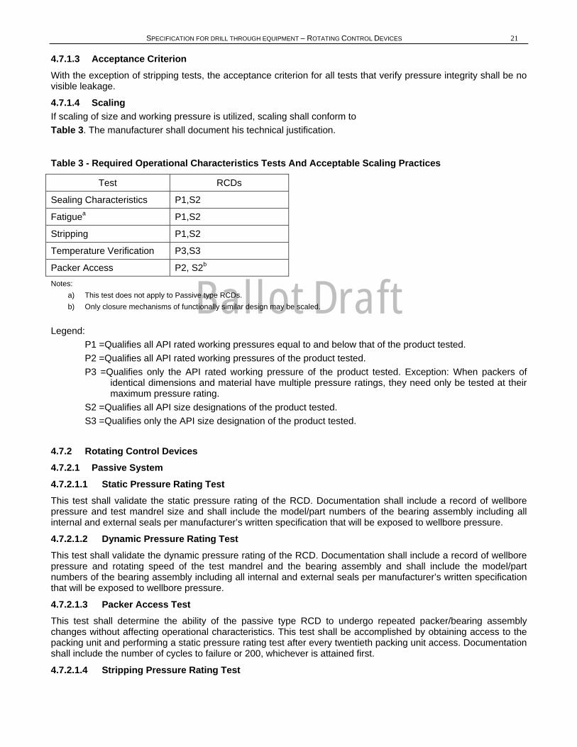
4.7.1.4 Scaling If scaling of size and working pressure is utilized, scaling shall conform to Table 3. The manufacturer shall document his technical justification.
Table 3 - Required Operational Characteristics Tests And Acceptable Scaling Practices
Test RCDs
Sealing Characteristics P1,S2
Fatiguea P1,S2
Stripping P1,S2
Temperature Verification P3,S3
Packer Access P2, S2b
Notes: a) This test does not apply to Passive type RCDs. b) Only closure mechanisms of functionally similar design may be scaled.
Legend: P1 =Qualifies all API rated working pressures equal to and below that of the product tested. P2 =Qualifies all API rated working pressures of the product tested. P3 =Qualifies only the API rated working pressure of the product tested. Exception: When packers of
identical dimensions and material have multiple pressure ratings, they need only be tested at their maximum pressure rating.
S2 =Qualifies all API size designations of the product tested. S3 =Qualifies only the API size designation of the product tested.
4.7.2 Rotating Control Devices 4.7.2.1 Passive System 4.7.2.1.1 Static Pressure Rating Test This test shall validate the static pressure rating of the RCD. Documentation shall include a record of wellbore pressure and test mandrel size and shall include the model/part numbers of the bearing assembly including all internal and external seals per manufacturer’s written specification that will be exposed to wellbore pressure.
4.7.2.1.2 Dynamic Pressure Rating Test This test shall validate the dynamic pressure rating of the RCD. Documentation shall include a record of wellbore pressure and rotating speed of the test mandrel and the bearing assembly and shall include the model/part numbers of the bearing assembly including all internal and external seals per manufacturer’s written specification that will be exposed to wellbore pressure.
4.7.2.1.3 Packer Access Test This test shall determine the ability of the passive type RCD to undergo repeated packer/bearing assembly changes without affecting operational characteristics. This test shall be accomplished by obtaining access to the packing unit and performing a static pressure rating test after every twentieth packing unit access. Documentation shall include the number of cycles to failure or 200, whichever is attained first.
4.7.2.1.4 Stripping Pressure Rating Test
Ballot Draft
22 API SPECIFICATION 16RCD
This test shall validate the stripping pressure rating of a specific model RCD packer element while stripping a minimum of 400 tool joints at the manufacturers specified stripping pressure rating. Documentation shall include a record of wellbore pressure and temperature, mandrel size and tool joint diameter, test fluid and shall include the model/part numbers of packing element. 4.7.2.1.5 Stripping Life Test This test shall determine the ability of the passive packing unit to maintain control of wellbore pressure while stripping test mandrel and tool joints through the closed packing unit without leaking fluid in excess of volume pulled through (due to mandrel geometry) while stripping out. The stripping test shall be conducted against a maximum wellbore pressure (manufacturers specified stripping pressure rating) to qualify the element for a specific stripping pressure. Documentation shall include:
a) Wellbore pressure used during the test.
b) Wellbore fluid used during the test.
c) Record of reciprocating speed.
d) Equivalent length of pipe and number of tool joints stripped or 1000 tool joints, whichever is attained first.
e) Wellbore fluid pulled through volume measured during the test.
f) Record of the temperature conditions during the test (ambient and surface temperature of mandrel).
4.7.2.1.6 Fatigue Test A fatigue test is not required for the passive type RCD packing unit.
4.7.2.2 Active System 4.7.2.2.1 Static Pressure Rating Test This test shall validate the static pressure rating of the RCD. Documentation shall include a record of wellbore pressure and test mandrel size and shall include the model/part numbers of the bearing assembly including all internal and external seals per manufacturer’s written specification that will be exposed to wellbore pressure.
4.7.2.2.2 Sealing Characteristics Test - Active This test shall determine the closing pressure necessary and the maximum allowable rotational speed to maintain a seal as a function of wellbore pressures up to full dynamic pressure rating of the Active Type RCD. The test is conducted on a drill pipe mandrel and on open hole conditions (non rotating). The test is conducted on a drill pipe mandrel sized for the minimum drill pipe OD that the packer can be used with, as specified by the manufacturer. This test shall consist of four parts for the Hybrid-active packer element:
4.7.2.2.3 Constant Wellbore Pressure Test This test shall determine the actual closing pressure required to maintain a wellbore pressure seal on the test mandrel. Documentation shall include a record of wellbore pressure vs. closing pressure.
4.7.2.2.4 Constant Closing Pressure Test This test shall determine the maximum wellbore pressure obtainable for a given closing pressure with the Active Type RCD closed on the test mandrel. Documentation shall include a record of wellbore pressure vs. closing pressure.
4.7.2.2.5 Full Closure Pressure Test This test is required for any RCD that the manufacturer specifies as capable of CSO. This test shall determine the closing pressure required to seal on the open hole at one half rated static pressure. Documentation shall include a record of wellbore pressure vs. closing pressure.
4.7.2.2.6 Dynamic Pressure Rating Test This test shall validate the dynamic pressure rating of the RCD. Documentation shall include a record of wellbore pressure and rotating speed of the test mandrel and the bearing assembly and shall include the model/part numbers of the bearing assembly including all internal and external seals per manufacturer’s written specification that will be exposed to wellbore pressure.
4.7.2.2.7 Fatigue Test
Ballot Draft
SPECIFICATION FOR DRILL THROUGH EQUIPMENT – ROTATING CONTROL DEVICES 23
This test shall determine the ability of an active type RCD to maintain a 50-120 psi and rated static pressure seal throughout repeated closings and openings. Documentation shall include:
a) Packing element inside diameter (I.D.) after every twentieth cycle vs. time up to 30 minutes.
b) The number of cycles to failure to maintain a seal or 364 close/open cycles and 52 pressure cycles, whichever is attained first.
4.7.2.2.8 Packer Access Test This test shall determine the ability of the active type RCD to undergo repeated packer changes without affecting operational characteristics. This test shall be accomplished by obtaining access to the packing unit and performing a static pressure rating test after every twentieth packing unit access. Documentation shall include the number of cycles to failure or 200, whichever is attained first.
4.7.2.2.9 Stripping Pressure Rating Test This test shall validate the stripping pressure rating of a specific model RCD packer element while stripping a minimum of 400 tool joints at the manufacturers specified stripping pressure rating. Documentation shall include a record of wellbore pressure and temperature, mandrel size and tool joint diameter, test fluid and shall include the model/part numbers of packing element. 4.7.2.2.10 Stripping Life Test This test shall determine the ability of the active packing unit to maintain control of wellbore pressure while stripping test mandrel and tool joints through the closed packing unit without leaking fluid in excess of volume pulled through (due to mandrel geometry) while stripping out. The stripping test shall be conducted against a maximum wellbore pressure (manufacturers specified stripping pressure rating) to qualify the element for a specific stripping pressure. Documentation shall include:
a) Wellbore pressure used during the test.
b) Wellbore fluid used during the test.
c) Record of reciprocating speed.
d) Equivalent length of pipe and number of tool joints stripped or 1000 tool joints, whichever is attained first.
e) Wellbore fluid pulled through volume measured during the test.
f) Record of the temperature conditions during the test (ambient and surface temperature of mandrel).
4.7.2.3 Hybrid System A hybrid system in the context of this specification is a RCD that combines a passive type packer element with a packer element that requires an external hydraulic pressure source to provide the closure force required to maintain a seal against wellbore pressures. Both elements must independently maintain a seal against wellbore pressures up to the full rated static pressure of the RCD. Each element in the hybrid design must be tested to this specification independently.
4.7.2.3.1 Static Pressure Rating Test This test shall validate the static pressure rating of the RCD. Documentation shall include a record of wellbore pressure and test mandrel size and shall include the model/part numbers of the bearing assembly including all internal and external seals per manufacturer’s written specification that will be exposed to wellbore pressure.
4.7.2.3.2 Stripping Pressure Rating Test This test shall validate the stripping pressure rating of a specific model RCD packer element while stripping a minimum of 400 tool joints at the manufacturers specified stripping pressure rating. Documentation shall include a record of wellbore pressure and temperature, mandrel size and tool joint diameter, test fluid and shall include the model/part numbers of packing element. 4.7.2.3.3 Dynamic Pressure Rating Test This test shall validate the dynamic pressure rating of the RCD. Documentation shall include a record of wellbore pressure and rotating speed of the test mandrel and the bearing assembly and shall include the model/part numbers of the bearing assembly including all internal and external seals per manufacturer’s written specification
Ballot Draft
24 API SPECIFICATION 16RCD
that will be exposed to wellbore pressure. In the event that each packer is associated with an independent bearing assembly, then each bearing assembly in the hybrid design must be tested to this specification independently.
4.7.2.3.4 Packer Access Test This test shall determine the ability of the Hybrid type RCD to undergo repeated packer/bearing assembly changes without affecting operational characteristics. This test shall be accomplished by obtaining access to the packing unit and performing a static pressure rating test after every twentieth packing unit access. Documentation shall include the number of cycles to failure or 200, whichever is attained first.
4.7.2.3.5 Stripping Life Test This test shall determine the ability of the passive and active packing units to maintain control of wellbore pressure while stripping test mandrel and tool joints through the closed packing unit without leaking fluid in excess of volume pulled through (due to mandrel geometry) while stripping out. The stripping test shall be conducted against a maximum wellbore pressure (manufacturers specified stripping pressure rating) to qualify the element for a specific stripping pressure. Documentation shall include:
a) Wellbore pressure used during the test.
b) Wellbore fluid used during the test.
c) Record of reciprocating speed.
d) Equivalent length of pipe and number of tool joints stripped or 1000 tool joints, whichever is attained first.
e) Wellbore fluid pulled through volume measured during the test.
f) Record of the temperature conditions during the test (ambient and surface temperature of mandrel).
4.7.2.3.6 Sealing Characteristics Test - Active This test shall determine the closing pressure necessary and the maximum allowable rotational speed to maintain a seal as a function of wellbore pressures up to full dynamic pressure rating of the Hybrid Type RCD. The test is conducted on a drill pipe mandrel and on open hole conditions (non rotating). The test is conducted on a drill pipe mandrel sized for the minimum drill pipe OD that the packer can be used with, as specified by the manufacturer. This test shall consist of four parts for the Hybrid-active packer element:
4.7.2.3.7 Constant Wellbore Pressure Test This test shall determine the actual closing pressure required to maintain a wellbore pressure seal on the test mandrel. Documentation shall include a record of wellbore pressure vs. closing pressure.
4.7.2.3.8 Constant Closing Pressure Test This test shall determine the maximum wellbore pressure obtainable for a given closing pressure with the Hybrid-active Type packer closed on the test mandrel. Documentation shall include a record of wellbore pressure vs. closing pressure.
4.7.2.3.9 Full Closure Pressure Test This test is required for any Hybrid type RCD that the manufacturer specifies as capable of CSO. This test shall determine the closing pressure required to seal on the open hole at one half rated static pressure. Documentation shall include a record of wellbore pressure vs. closing pressure.
4.7.2.3.10 Fatigue Test This test shall determine the ability of a Hybrid-active type RCD to maintain a 50-120 psi and rated static pressure seal throughout repeated closings and openings. Documentation shall include:
a) Packing element inside diameter (I.D.) after every twentieth cycle vs. time up to 30 minutes.
b) The number of cycles to failure to maintain a seal or 364 close/open cycles and 52 pressure cycles, whichever is attained first.
Ballot Draft
SPECIFICATION FOR DRILL THROUGH EQUIPMENT – ROTATING CONTROL DEVICES 25
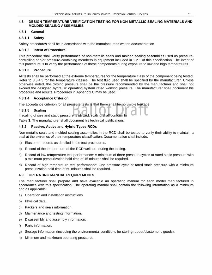
4.8 DESIGN TEMPERATURE VERIFICATION TESTING FOR NON-METALLIC SEALING MATERIALS AND MOLDED SEALING ASSEMBLIES
4.8.1 General 4.8.1.1 Safety Safety procedures shall be in accordance with the manufacturer’s written documentation.
4.8.1.2 Intent of Procedure This procedure shall verify performance of non-metallic seals and molded sealing assemblies used as pressure-controlling and/or pressure-containing members in equipment included in 1.2.1 of this specification. The intent of this procedure is to verify the performance of these components during exposure to low and high temperatures.
4.8.1.3 Procedure All tests shall be performed at the extreme temperatures for the temperature class of the component being tested. Refer to 8.3.4.3 for the temperature classes. The test fluid used shall be specified by the manufacturer. Unless otherwise noted, the closing pressure shall be the pressure recommended by the manufacturer and shall not exceed the designed hydraulic operating system rated working pressure. The manufacturer shall document his procedure and results. Procedures in Appendix C may be used.
4.8.1.4 Acceptance Criterion The acceptance criterion for all pressure tests is that there shall be no visible leakage.
4.8.1.5 Scaling If scaling of size and static pressure is utilized, scaling shall conform to Table 3. The manufacturer shall document his technical justifications.
4.8.2 Passive, Active and Hybrid Types RCDs Non-metallic seals and molded sealing assemblies in the RCD shall be tested to verify their ability to maintain a seal at the extremes of their temperature classification. Documentation shall include:
a) Elastomer records as detailed in the test procedures.
b) Record of the temperature of the RCD wellbore during the testing.
c) Record of low temperature test performance: A minimum of three pressure cycles at rated static pressure with a minimum pressurization hold time of 15 minutes shall be required.
d) Record of high temperature test performance: One pressure cycle at rated static pressure with a minimum pressurization hold time of 60 minutes shall be required.
4.9 OPERATING MANUAL REQUIREMENTS The manufacturer shall prepare and have available an operating manual for each model manufactured in accordance with this specification. The operating manual shall contain the following information as a minimum and as applicable:
a) Operation and installation instructions.
b) Physical data.
c) Packers and seals information.
d) Maintenance and testing information.
e) Disassembly and assembly information.
f) Parts information.
g) Storage information (including the environmental conditions for storing rubber/elastomeric goods).
h) Minimum and maximum operating pressures.
Ballot Draft
26 API SPECIFICATION 16RCD
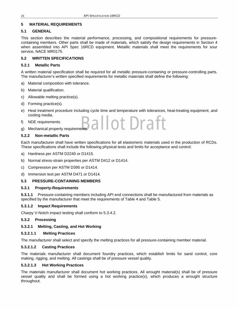
5 MATERIAL REQUIREMENTS 5.1 GENERAL This section describes the material performance, processing, and compositional requirements for pressure-containing members. Other parts shall be made of materials, which satisfy the design requirements in Section 4 when assembled into API Spec 16RCD equipment. Metallic materials shall meet the requirements for sour service, NACE MR0175.
5.2 WRITTEN SPECIFICATIONS 5.2.1 Metallic Parts A written material specification shall be required for all metallic pressure-containing or pressure-controlling parts. The manufacturer’s written specified requirements for metallic materials shall define the following:
a) Material composition with tolerance.
b) Material qualification.
c) Allowable melting practice(s).
d) Forming practice(s).
e) Heat treatment procedure including cycle time and temperature with tolerances, heat-treating equipment, and cooling media.
f) NDE requirements.
g) Mechanical property requirements.
5.2.2 Non-metallic Parts Each manufacturer shall have written specifications for all elastomeric materials used in the production of RCDs. These specifications shall include the following physical tests and limits for acceptance and control:
a) Hardness per ASTM D2240 or D1415.
b) Normal stress-strain properties per ASTM D412 or D1414.
c) Compression per ASTM D395 or D1414.
d) Immersion test per ASTM D471 or D1414.
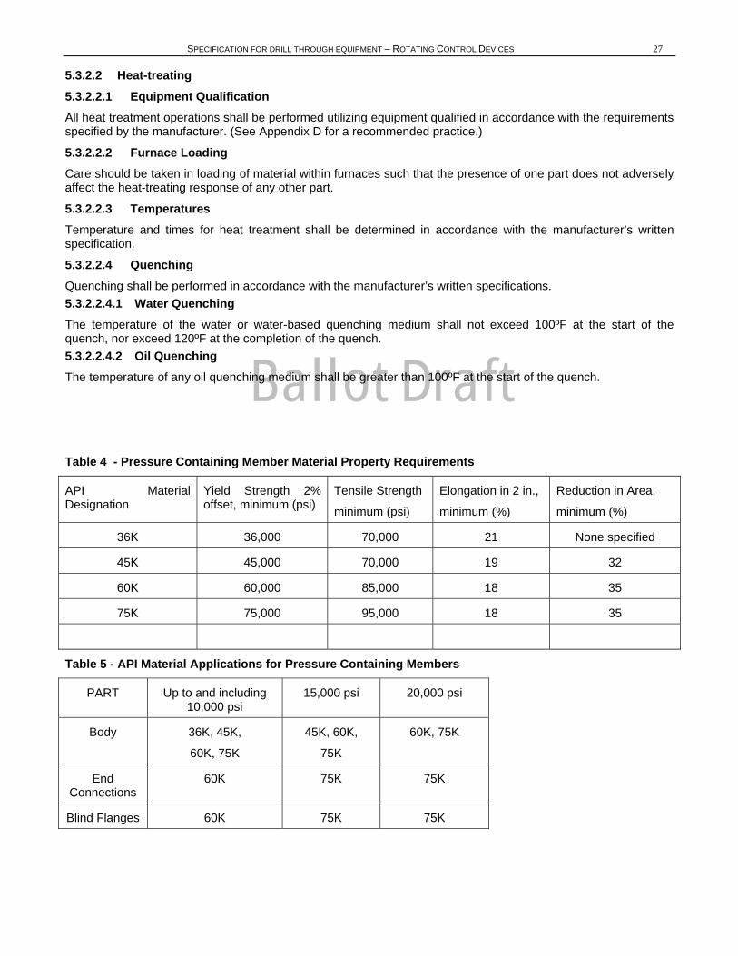
5.3 PRESSURE-CONTAINING MEMBERS 5.3.1 Property-Requirements 5.3.1.1 Pressure-containing members including API end connections shall be manufactured from materials as specified by the manufacturer that meet the requirements of Table 4 and Table 5.
5.3.1.2 Impact Requirements Charpy V-Notch impact testing shall conform to 5.3.4.2.
5.3.2 Processing 5.3.2.1 Melting, Casting, and Hot Working 5.3.2.1.1 Melting Practices The manufacturer shall select and specify the melting practices for all pressure-containing member material.
5.3.2.1.2 Casting Practices The materials manufacturer shall document foundry practices, which establish limits for sand control, core making, rigging, and melting. All castings shall be of pressure vessel quality.
5.3.2.1.3 Hot Working Practices The materials manufacturer shall document hot working practices. All wrought material(s) shall be of pressure vessel quality and shall be formed using a hot working practice(s), which produces a wrought structure throughout.
Ballot Draft
SPECIFICATION FOR DRILL THROUGH EQUIPMENT – ROTATING CONTROL DEVICES 27
5.3.2.2 Heat-treating 5.3.2.2.1 Equipment Qualification All heat treatment operations shall be performed utilizing equipment qualified in accordance with the requirements specified by the manufacturer. (See Appendix D for a recommended practice.)
5.3.2.2.2 Furnace Loading Care should be taken in loading of material within furnaces such that the presence of one part does not adversely affect the heat-treating response of any other part.
5.3.2.2.3 Temperatures Temperature and times for heat treatment shall be determined in accordance with the manufacturer’s written specification.
5.3.2.2.4 Quenching Quenching shall be performed in accordance with the manufacturer’s written specifications. 5.3.2.2.4.1 Water Quenching The temperature of the water or water-based quenching medium shall not exceed 100ºF at the start of the quench, nor exceed 120ºF at the completion of the quench. 5.3.2.2.4.2 Oil Quenching The temperature of any oil quenching medium shall be greater than 100ºF at the start of the quench.
Table 4 - Pressure Containing Member Material Property Requirements
API Material Designation
Yield Strength 2% offset, minimum (psi)
Tensile Strength
minimum (psi)
Elongation in 2 in.,
minimum (%)
Reduction in Area,
minimum (%)
36K 36,000 70,000 21 None specified
45K 45,000 70,000 19 32
60K 60,000 85,000 18 35
75K 75,000 95,000 18 35
Table 5 - API Material Applications for Pressure Containing Members
PART Up to and including 10,000 psi
15,000 psi 20,000 psi
Body 36K, 45K,
60K, 75K
45K, 60K,
75K
60K, 75K
End Connections
60K 75K 75K
Blind Flanges 60K 75K 75K
Ballot Draft
SPECIFICATION FOR DRILL THROUGH EQUIPMENT – RCDS 28 5.3.3 Chemical Compositions 5.3.3.1 General 5.3.3.1.1 The manufacturer shall specify the chemical range of material used to manufacture pressure containing members.
5.3.3.1.2 Material composition shall be determined on a heat basis (or a remelt ingot basis for remelt grade materials) in accordance with the manufacturer’s written specification.
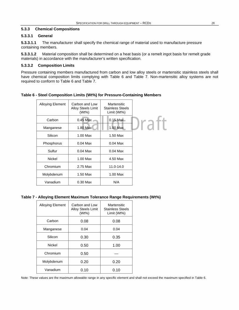
5.3.3.2 Composition Limits Pressure containing members manufactured from carbon and low alloy steels or martensitic stainless steels shall have chemical composition limits complying with Table 6 and Table 7. Non-martensitic alloy systems are not required to conform to Table 6 and Table 7.
Table 6 - Steel Composition Limits (Wt%) for Pressure-Containing Members
Alloying Element Carbon and Low Alloy Steels Limit
(Wt%)
Martensitic Stainless Steels
Limit (Wt%)
Carbon 0.45 Max 0.15 Max
Manganese 1.80 Max 1.00 Max
Silicon 1.00 Max 1.50 Max
Phosphorus 0.04 Max 0.04 Max
Sulfur 0.04 Max 0.04 Max
Nickel 1.00 Max 4.50 Max
Chromium 2.75 Max 11.0-14.0
Molybdenum 1.50 Max 1.00 Max
Vanadium 0.30 Max N/A
Table 7 - Alloying Element Maximum Tolerance Range Requirements (Wt%)
Alloying Element Carbon and Low Alloy Steels Limit
(Wt%)
Martensitic Stainless Steels
Limit (Wt%)
Carbon 0.08 0.08
Manganese 0.04 0.04
Silicon 0.30 0.35
Nickel 0.50 1.00
Chromium 0.50 —
Molybdenum 0.20 0.20
Vanadium 0.10 0.10
Note: These values are the maximum allowable range in any specific element and shall not exceed the maximum specified in Table 6.
Ballot Draft
SPECIFICATION FOR DRILL THROUGH EQUIPMENT – ROTATING CONTROL DEVICES 29
5.3.3.3 Alloy Element Range The alloy element range shall conform to Table 7.
5.3.4 Material Qualification 5.3.4.1 Tensile Testing 5.3.4.1.1 Test Specimens Tensile test specimens shall be removed from a Qualification Test Coupon (QTC) as described in 5.3.5. This QTC shall be used to qualify a heat and the products produced from that heat.
5.3.4.1.2 Methods 5.3.4.1.2.1 Tensile tests shall be performed at room temperature in accordance with the procedures specified in ASTM A370. 5.3.4.1.2.2 A minimum of one tensile test shall be performed. The results of the tensile test(s) shall satisfy the applicable requirements of Table 4. If the results of the first tensile tests do not satisfy the applicable requirements, two additional tensile tests may be performed in an effort to qualify the material. The results of each of these additional tests shall satisfy the requirements of Table 4.
5.3.4.2 Impact Testing 5.3.4.2.1 Sampling Impact testing shall be performed on each heat of material used for pressure-containing members.
5.3.4.2.2 Test Specimens Impact test specimens shall be removed from a QTC as prescribed in 5.3.5. This QTC shall be used to qualify a heat and the products produced from that heat.
5.3.4.2.3 Size Standard size specimens, 10 mm x 10 mm in cross section, shall be used except where there is insufficient material, in which case the next smaller standard size specimen obtainable shall be used. When it is necessary to prepare sub-size specimens, the reduced dimension shall be in the direction parallel to the base of the V-Notch.
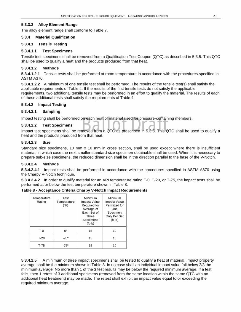
5.3.4.2.4 Methods 5.3.4.2.4.1 Impact tests shall be performed in accordance with the procedures specified in ASTM A370 using the Charpy V-Notch technique. 5.3.4.2.4.2 In order to qualify material for an API temperature rating T-0, T-20, or T-75, the impact tests shall be performed at or below the test temperature shown in Table 8. Table 8 - Acceptance Criteria Charpy V-Notch Impact Requirements
Temperature Rating
Test Temperature
(ºF)
Minimum Impact Value Required for Average of Each Set of
Three Specimens
(ft-lb)
Minimum Impact Value Permitted for
One Specimen
Only Per Set (ft-lb)
T-0 0º 15 10
T-20 -20º 15 10
T-75 -75º 15 10
5.3.4.2.5 A minimum of three impact specimens shall be tested to qualify a heat of material. Impact property average shall be the minimum shown in Table 8. In no case shall an individual impact value fall below 2/3 the minimum average. No more than 1 of the 3 test results may be below the required minimum average. If a test fails, then 1 retest of 3 additional specimens (removed from the same location within the same QTC with no additional heat treatment) may be made. The retest shall exhibit an impact value equal to or exceeding the required minimum average.
Ballot Draft
30 API SPECIFICATION 16RCD
5.3.4.2.6 Specimen Orientation The values listed in Table 8 are the minimum acceptable values for forgings and wrought products tested in the transverse direction and for castings and weld qualifications. Forgings and wrought products may be tested in the longitudinal direction instead of the transverse direction and then shall exhibit 20 ft-lb minimum average value.
5.3.5 Qualification Test Coupons (QTC) 5.3.5.1 General 5.3.5.1.1 The properties exhibited by the QTC shall represent the properties of the material comprising the equipment it qualifies. A single QTC may be used to represent the impact and/or tensile properties of components produced from the same heat provided it satisfies the requirements of this specification.
5.3.5.1.2 When the QTC is a trepanned core or a prolongation removed from a production part, the QTC may only qualify parts having the same or smaller equivalent round (ER).
5.3.5.1.3 A QTC may only qualify material and parts produced from the same heat. (Remelt heat may be qualified on a master heat basis.)
5.3.5.2 Equivalent Round 5.3.5.2.1 General The size of a QTC for a part shall be determined using the ER methods in the following sections.
5.3.5.2.2 ER Methods Figure 4 illustrates the basic models for determining the ER of simple solid and hollowed parts and more complicated equipment. The ER of a part shall be determined using the actual dimensions of the part in the “as heat treated” condition.
5.3.5.2.3 Size Requirements The ER of the QTC shall be equal to or greater than the dimensions of the part it qualifies, except the size of the QTC is not required to exceed 5 inches ER.
5.3.5.3 Processing 5.3.5.3.1 Melting, Casting, and Hot Working 5.3.5.3.1.1 Melting Practices In no case shall the QTC be processed using a melting practice(s) cleaner than that of the material it qualifies [e.g., a QTC made from a remelt grade or vacuum degassed material may not qualify material from the same primary melt which has not experienced the identical melting practice(s)]. Remelt grade material removed from a single remelt ingot may be used to qualify other remelt grade material which has been processed in like manner and is from the same primary melt. No additional alloying shall be performed on these individual remelt ingots. 5.3.5.3.1.2 Casting Practices The manufacturer shall use the same foundry practice(s) for the QTC as those used for the parts it qualifies to assure accurate representation. 5.3.5.3.1.3 Hot Working Practices The manufacturer shall use hot working ratios on the QTC, which are equal to or less than those used in processing the part it qualifies. The total hot work ratio for the QTC shall not exceed the total hot work ratio of the parts it qualifies.
5.3.5.3.2 Welding Welding on the QTC is prohibited except for attachment type welds.
5.3.5.3.3 Heat-treating 5.3.5.3.3.1 Equipment Qualification All heat treatment operations shall be performed utilizing production type equipment certified in accordance with the manufacturer’s written specification. Production type heat-treating equipment shall be considered equipment that is routinely used to process parts. 5.3.5.3.3.2 Methods
Ballot Draft
SPECIFICATION FOR DRILL THROUGH EQUIPMENT – ROTATING CONTROL DEVICES 31
5.3.5.3.3.3 The QTC shall experience the same specified heat treatment processing as the parts it qualifies. The QTC shall be heat treated using the manufacturer’s specified heat-treating procedures. 5.3.5.3.3.4 When the QTC is not heat treated as part of the same heat treatment load as the parts it qualifies, the austenitizing (or solution heat treat) temperatures for the QTC shall be within 25ºF of those for the parts. The tempering temperature for the part shall be no lower than 25ºF below that of the QTC. The upper limit shall be no higher than permitted by the heat treat procedure for that material. The cycle time of the QTC at each temperature shall not exceed that for the parts.
5.3.5.4 Tensile and Impact Testing - Test Specimens 5.3.5.4.1 When tensile and/or impact test specimens are required, they shall be removed from a QTC after the final QTC heat treatment cycle. It is allowable to remove tensile and impact specimens from multiple QTCs as long as the multiple QTCs had the same heat treatment cycle(s).
5.3.5.4.2 Tensile and impact specimens shall be removed from the QTC such that their longitudinal centerline axis is wholly within the center core 1/4T envelope for a solid QTC or within 1/4-inch of the mid-thickness of the thickest section of a hollow QTC (refer to Figure 4).
For QTCs larger than the size specified in 5.3.5.2.3, the test specimens need not be removed from a location farther from the QTC surface than would be required if the specified QTC size were used.
5.3.5.4.3 When a sacrificial production part is used as the QTC, the test specimens shall be removed from a section of the part meeting the size requirements of the QTC for that production part as described in 5.3.5.2.
5.3.5.5 Hardness Testing 5.3.5.5.1 General A hardness test shall be performed on the QTC after the final heat treatment cycle.
5.3.5.5.2 Methods Hardness testing shall be performed in accordance with procedures specified in ASTM A370 or ASTM E10 as appropriate.
6 WELDING REQUIREMENTS 6.1 GENERAL 6.1.1 All welding of components exposed to wellbore fluid shall comply with the welding requirements of NACE MR0175. Verification of compliance shall be established through the implementation of the manufacturer’s written Welding Procedure Specification (WPS) and the supporting Procedure Qualification Record (PQR).
6.1.2 When material specifications for pressure-containing and pressure-retaining components require impact testing, verification of compliance shall be established through the implementation of the manufacturer’s WPS and supporting PQR.
6.2 WELDMENT DESIGN AND CONFIGURATION 6.2.1 Pressure Containing Fabrication Weldments Pressure-containing fabrication weldments contain and are wetted by wellbore fluid.
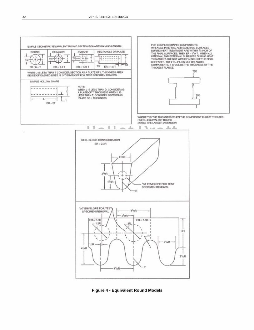
Ballot Draft
32 API SPECIFICATION 16RCD
.
Figure 4 - Equivalent Round Models
Ballot Draft
SPECIFICATION FOR DRILL THROUGH EQUIPMENT – RCDS 33 6.2.1.1 Only full penetration welds fabricated in accordance with the manufacturer’s written specification shall be used. Appendix E is provided for reference.
6.2.1.2 Welding and completed welds shall meet the quality control requirements of Section 7 of this specification.
6.2.2 Load Bearing Weldment Load bearing weldments are those subject to external loads and not exposed to wellbore fluids.
6.2.2.1 Joint design shall be in accordance with the manufacturer’s written procedures.
6.2.2.2 Welding and completed welds shall meet the quality control requirements of Section 7 of this specification.
6.2.3 Weld Repairs Weld repairs to pressure-containing members.
6.2.3.1 All repair welding shall be done in accordance with the manufacturer’s written specification. All major repair welds performed subsequent to original heat treatment shall be mapped. Manufacturers shall have a written procedure defining major repair.
6.2.3.2 Welding and completed welds shall meet the requirement of Section 7 of this specification.
6.2.4 Weld Surfacing (Overlay) for Corrosion Resistance and Wear Resistance for Material Surface Property Controls
6.2.4.1 Corrosion-Resistant API Ring Grooves Standard dimensions for the preparation of API Type SR ring grooves for overlay are specified in API Spec 16A. Standard dimensions for API Type R and BX ring grooves are specified in API Spec 6A.
6.2.4.2 Corrosion-Resistant and Wear-Resistant Overlays Other Than Ring Grooves 6.2.4.2.1 The manufacturer shall use a written procedure that provides controls for consistently meeting the manufacturer specified material surface properties in the final machined condition. As a minimum this shall include inspection methods and acceptance criteria.
6.2.4.2.2 Qualification shall be in accordance with Article II and III of ASME Boiler & Pressure Vessel Code Section IX for corrosion-resistant weld metal overlay or hardfacing weld metal overlay as applicable.
6.2.4.2.3 Mechanical Properties Mechanical properties of the base material shall retain the minimum mechanical property requirements after thermal treatment. The manufacturer shall specify the methods to assure these mechanical properties and record the results as a part of the PQR.
6.3 WELDING CONTROLS 6.3.1 Procedures The manufacturer’s system for controlling welding shall include procedures for monitoring, updating, and controlling the qualification of welders and welding operators and the use of welding procedure specifications.
Ballot Draft
34 API SPECIFICATION 16RCD
6.3.2 Application 6.3.2.1 Welding shall be performed by personnel qualified in accordance with the requirements of 6.4.1.
6.3.2.2 Welding shall be performed in accordance with written WPS and qualified in accordance with Article II of ASME Section IX. The WPS shall describe all the essential, non-essential and supplementary essential (when required—see ASME Section IX) variables. Welders and welding operators shall have access to, and shall comply with, the welding parameters as defined in the WPS.
6.3.3 Designed Welds 6.3.3.1 All welds that are considered part of the design of a production part shall be specified by the manufacturer to describe the requirements for the intended weld.
6.3.3.2 Dimensions of groove and fillet welds with tolerances shall be documented in the manufacturer’s specification. Appendix E of this specification depicts some typical joint designs.
6.3.4 Preheating Preheating of assemblies or parts, when required, shall be performed to manufacturer’s written procedures.
6.3.5 Instrument Calibration Instruments to verify temperature, voltage, and amperage shall be serviced and calibrated in accordance with the written specification of the manufacturer performing the welding.
6.3.6 Materials 6.3.6.1 Welding Consumables 6.3.6.1.1 Welding consumables shall conform to the American Welding Society’s (AWS) or consumable manufacturer’s approved specifications.
6.3.6.1.2 The manufacturer shall have a written procedure for storage and control of weld consumables. Materials of low hydrogen type shall be stored and used as recommended by the consumable manufacturer to retain their original low hydrogen properties.
6.3.6.2 Deposited Weld Metal Properties The deposited weld metal mechanical properties shall meet or exceed the minimum specified mechanical properties of the base material. Verification of properties shall be established through the implementation of the manufacturer’s WPS and supporting PQR. When materials of differing strength are joined, the weld metal shall meet the minimum requirements of the lesser material.
6.3.7 Post-Weld Heat Treatment 6.3.7.1 Post-weld heat treatment of components shall be in accordance with the manufacturer’s written procedures.
6.3.7.2 Furnace post-weld heat treatment shall be performed in equipment meeting the requirements specified by the manufacturer.
6.3.7.3 Local post-weld heat treatment shall consist of heating a band around a weld at a temperature within the range specified in the qualified WPS. The minimum width of the controlled band adjacent to the weld, on the face of the greatest weld width, shall be the thickness of the weld. Localized flame heating is permitted provided the flame is baffled to prevent direct impingement on the weld and base material.
6.4 WELDING PROCEDURE AND PERFORMANCE QUALIFICATIONS 6.4.1 General All weld procedures, welders, and welding operators shall be qualified in accordance with the qualification and test methods of Section IX, ASME Boiler and Pressure Vessel Code, as amended below.
6.4.1.1 Base Metals 6.4.1.1.1 The manufacturer may use ASME Section IX P number materials.
6.4.1.1.2 The manufacturer may establish an equivalent P number (EP) grouping for low alloy steels not listed in ASME Section IX with nominal carbon content equal to or less than 0.35 percent.
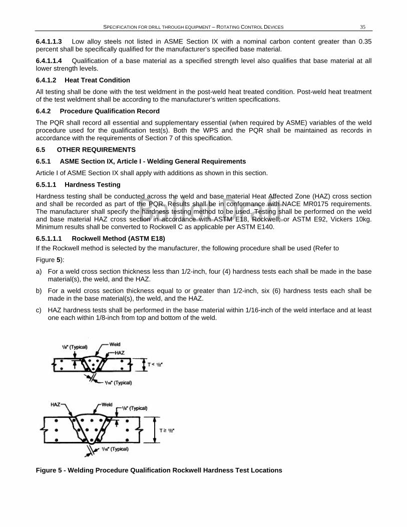
Ballot Draft
SPECIFICATION FOR DRILL THROUGH EQUIPMENT – ROTATING CONTROL DEVICES 35
6.4.1.1.3 Low alloy steels not listed in ASME Section IX with a nominal carbon content greater than 0.35 percent shall be specifically qualified for the manufacturer’s specified base material.
6.4.1.1.4 Qualification of a base material as a specified strength level also qualifies that base material at all lower strength levels.
6.4.1.2 Heat Treat Condition All testing shall be done with the test weldment in the post-weld heat treated condition. Post-weld heat treatment of the test weldment shall be according to the manufacturer’s written specifications.
6.4.2 Procedure Qualification Record The PQR shall record all essential and supplementary essential (when required by ASME) variables of the weld procedure used for the qualification test(s). Both the WPS and the PQR shall be maintained as records in accordance with the requirements of Section 7 of this specification.
6.5 OTHER REQUIREMENTS 6.5.1 ASME Section IX, Article I - Welding General Requirements Article I of ASME Section IX shall apply with additions as shown in this section.
6.5.1.1 Hardness Testing Hardness testing shall be conducted across the weld and base material Heat Affected Zone (HAZ) cross section and shall be recorded as part of the PQR. Results shall be in conformance with NACE MR0175 requirements. The manufacturer shall specify the hardness testing method to be used. Testing shall be performed on the weld and base material HAZ cross section in accordance with ASTM E18, Rockwell; or ASTM E92, Vickers 10kg. Minimum results shall be converted to Rockwell C as applicable per ASTM E140.
6.5.1.1.1 Rockwell Method (ASTM E18) If the Rockwell method is selected by the manufacturer, the following procedure shall be used (Refer to
Figure 5):
a) For a weld cross section thickness less than 1/2-inch, four (4) hardness tests each shall be made in the base material(s), the weld, and the HAZ.
b) For a weld cross section thickness equal to or greater than 1/2-inch, six (6) hardness tests each shall be made in the base material(s), the weld, and the HAZ.
c) HAZ hardness tests shall be performed in the base material within 1/16-inch of the weld interface and at least one each within 1/8-inch from top and bottom of the weld.
Figure 5 - Welding Procedure Qualification Rockwell Hardness Test Locations

Ballot Draft
36 API SPECIFICATION 16RCD
6.5.1.1.2 Vickers Method (ASTM E92) If the Vickers method is selected by the manufacturer, the following procedure shall be used (Refer to
Figure 6):
a) For a weld cross section thickness less than 1/2-inch, four (4) hardness tests each shall be made in the base materials and the weld.
b) For a weld cross section thickness equal to or greater than 1/2-inch, six (6) hardness tests each shall be made in the base material(s) and the weld.
c) Multiple HAZ hardness tests equally spaced 1/8-inch apart shall be performed in each of the base materials within 0.010-inch of the weld interface and at least one within 1/16-inch from the top and the bottom of the weld.
Figure 6 - Welding Procedure Qualification Vickers Hardness Test Locations
6.5.1.1.3 Hardness Testing (Optional) Minimum mechanical properties: For the purpose of hardness inspection and qualifying production weldments, a minimum of three hardness tests in the weld metal shall be made and recorded as part of the PQR. These tests shall be made by the same methods used to inspect production weldments. These tests may be used to qualify weld metal with hardness less than shown in 7.5.1.3 by the method shown in the same section.
6.5.1.2 Impact Testing 6.5.1.2.1 When impact testing is required by the base material specification, the testing shall be performed in accordance with ASTM A370 using the Charpy V-Notch technique. Results of testing in the weld and base material HAZ shall meet the minimum requirements of the base material. Records of results shall become part of the PQR.
Ballot Draft
SPECIFICATION FOR DRILL THROUGH EQUIPMENT – ROTATING CONTROL DEVICES 37
6.5.1.2.2 When impact testing is required of the base material, one set of three test specimens shall be removed at the 1/4 thickness location of the test weldment for each of the weld metal and base material HAZ. The root of the notch shall be oriented normal to the surface of the test weldment and located as follows:
a) Weld metal specimens (three each) shall be 100 percent weld metal.
b) HAZ specimens (three each) shall include HAZ material as specified in the manufacturer’s written procedure.
c) When weld thickness of the product is equal to or greater than 2 inches, impact testing as defined in 6.5.1.2.2 shall be performed on weld metal and HAZ material removed within 1/4 thickness.
6.5.2 ASME Section IX, Article II—Welding Procedure Qualifications Article II of ASME Section IX shall apply with additions as shown in this section.
6.5.2.1 Heat Treatment The post-weld heat treatment of the test weldment and the production weldment shall be in the same range as that specified on the WPS. Allowable range for the post-weld heat treatment on the WPS shall be a nominal temperature ±25ºF. The stress relieving heat treatment(s) time(s) at temperature(s) of production parts shall be equal to or greater than that of the test weldment.
6.5.2.2 Chemical Analysis Chemical analysis of the base materials for the test weldment shall be obtained from the supplier or by testing and shall be part of the PQR.
6.5.2.3 Chemical Analysis Ring Groove Overlay For corrosion-resistant ring groove overlay, chemical analysis shall be performed in the weld metal in accordance with the requirements of ASME Section IX at a location of 0.125 inch or less from the original base metal surface. The chemical composition of the deposited weld metal at that location shall be as specified by the manufacturer. For 300 Series stainless steel, the chemical composition shall be within the following limits:
Nickel 8.0% Minimum
Chromium 16.0% Minimum
Carbon 0.08% Maximum
6.5.3 ASME Section IX, Article III—Welding Performance Qualifications Article III of ASME Section IX shall apply with additions as shown in this section.
6.5.3.1 Bolt, Tapped, and Blind Hold Repair Performance Qualification The welder or welding operator shall perform an additional repair welding performance qualification test using a mock-up hole. (Refer to Appendix E.) The repair welding qualification test hole shall be qualified by radiography according to Section 7 of this specification or shall be cross sectioned through the center line of the hole and both faces shall be examined by NDE in accordance with Section 7 of this specification. This evaluation shall include the total depth of the hole.
The repair weld qualification shall be restricted by the following essential variables for performance controls:
a) The hole diameter used for the performance qualification test is the minimum diameter qualified. Any hole with a greater diameter than the diameter used for the test shall be considered qualified.
b) The depth-to-diameter ratio of the test hole shall qualify all repairs to holes with the same or smaller depth-to-diameter ratio.
c) The performance qualification test shall have straight parallel walls. If any taper, counter bore, or other aid is used to enhance the hole configuration of the performance test, that configuration shall be considered an essential variable.
6.5.3.2 For welder performance qualification, ASME Section IX P-1 base metals may be used for the test coupon in place of the low alloy steels covered by.
6.5.4 ASME Section IX, Article IV—Welding Data Article IV of ASME Section IX shall apply as written.
Ballot Draft
38 API SPECIFICATION 16RCD
7 QUALITY CONTROL REQUIREMENTS 7.1 GENERAL This section specifies the requirements relative to Quality Control to assure that the equipment, materials, and services meet this specification. The following subjects are covered: a) Measuring and Test Equipment: 7.2. b) Quality Control Personnel Qualifications: 7.3. c) Quality Control Requirements For Equipment and Parts: 7.4. d) Quality Control Requirements For Specific Equipment and Parts: 7.5.
1. Pressure Containing and Pressure Controlling Parts: 7.5.1.
2. Studs and Nuts: 7.5.2.
3. Closure Bolting: 7.5.3.
4. Ring Gaskets: 7.5.4.
5. Non-Metallic Sealing Materials and Molded Sealing Assemblies: 7.5.5.
6. All Other RCD Parts: 7.5.6.
7. Assembled RCDs: 7.5.7
e) Quality Control Records: 7.6.
7.2 MEASURING AND TESTING EQUIPMENT 7.2.1 General All equipment used to inspect, test, or examine material or other equipment shall be identified, controlled, calibrated, and adjusted at specified intervals in accordance with documented manufacturer instructions, and shall be consistent with referenced industry standards to maintain the accuracy required by this specification.
7.2.2 Dimensional Measuring Equipment Dimensional measuring equipment shall be controlled and calibrated by the methods specified in MIL-STD-120 to maintain the accuracies specified by API and the manufacturer’s specification. Dimensional measuring equipment not covered by MIL-STD-120 shall be controlled and calibrated in accordance with the manufacturer’s written specification.
7.2.3 Pressure Measuring Devices 7.2.3.1 Type and Accuracy Test pressure-measuring devices shall be either pressure gages or pressure transducers and shall be accurate to at least ±0.5 percent of full scale range.
7.2.3.2 Pressure Range Pressure measurements shall be made at not less than 25 percent nor more than 75 percent of the full pressure span of the gauge.
7.2.3.3 Calibration Procedure Pressure-measuring Devices shall be periodically recalibrated with a master pressure-measuring device or a dead weight tester at 25 percent, 50 percent, and 75 percent of full scale.
7.2.3.4 Calibration Intervals 7.2.3.4.1 Intervals shall be established for calibrations based on repeatability and degree of usage of the pressure-measuring Devices.
7.2.3.4.2 Calibration intervals shall be a maximum of three months until recorded calibration history can be determined by the manufacturer and new intervals established.

Ballot Draft
SPECIFICATION FOR DRILL THROUGH EQUIPMENT – ROTATING CONTROL DEVICES 39
7.3 QUALITY CONTROL PERSONNEL QUALIFICATIONS 7.3.1 NDE Personnel NDE personnel shall be qualified in accordance with requirements specified in ASNT Recommended Practice SNT-TC-1A.
7.3.2 Visual Examination Personnel Personnel performing visual examinations shall have an annual eye examination in accordance with ASNT Recommended Practice SNT-TC-1A.
7.3.3 Welding Inspectors Personnel performing visual inspection of welding operations and completed welds shall be qualified and certified as follows:
a) AWS-certified welding inspector, or
b) AWS-certified associate welding inspector, or
c) Welding inspector certified by the manufacturer’s documented training program.
7.3.4 Other Personnel All personnel performing other quality control activities directly affecting material and product quality shall be qualified in accordance with the manufacturer’s documented requirements.
7.4 QUALITY CONTROL REQUIREMENTS FOR EQUIPMENT AND PARTS 7.4.1 General All equipment exposed to wellbore fluid shall comply with the requirements of NACE MR0175 in addition to specific requirements of this specification.
7.4.2 Materials Section 7.5.1 of this specification includes detailed qualification requirements for parts and qualification test coupons. It also includes heat-treating equipment qualification requirements.
7.4.3 Quality Control Instructions All quality control work shall be controlled by documented manufacturer’s instructions, which include appropriate methodology and acceptance criteria.
7.4.4 Nondestructive Examination (NDE) The manufacturer shall provide written instructions for NDE activities regarding the requirements of this specification and those of all applicable referenced specifications. All NDE instructions shall be approved by the manufacturer’s qualified Level III NDE personnel.
7.4.5 Acceptance Status The acceptance status of all equipment, parts and materials shall be indicated either on the equipment, parts or materials or in the records traceable to the equipment, parts, or materials.
7.5 QUALITY CONTROL REQUIREMENTS FOR SPECIFIC EQUIPMENT AND PARTS 7.5.1 Pressure-Containing and Pressure-Controlling Parts Pressure-containing and pressure-controlling parts exposed to wellbore fluid except for studs and nuts, closure bolting, ring gaskets, non-metallic sealing materials, molded sealing assemblies, and metallic inserts in molded assemblies. (See 7.5.2, 7.5.3, 7.5.4, and 7.5.5.)
7.5.1.1 Tensile Testing 7.5.1.1.1 Pressure Containing Parts Methods and acceptance criteria shall be in accordance with 5.3.4.
7.5.1.1.2 Pressure-Controlling Parts Exposed to Wellbore Fluid
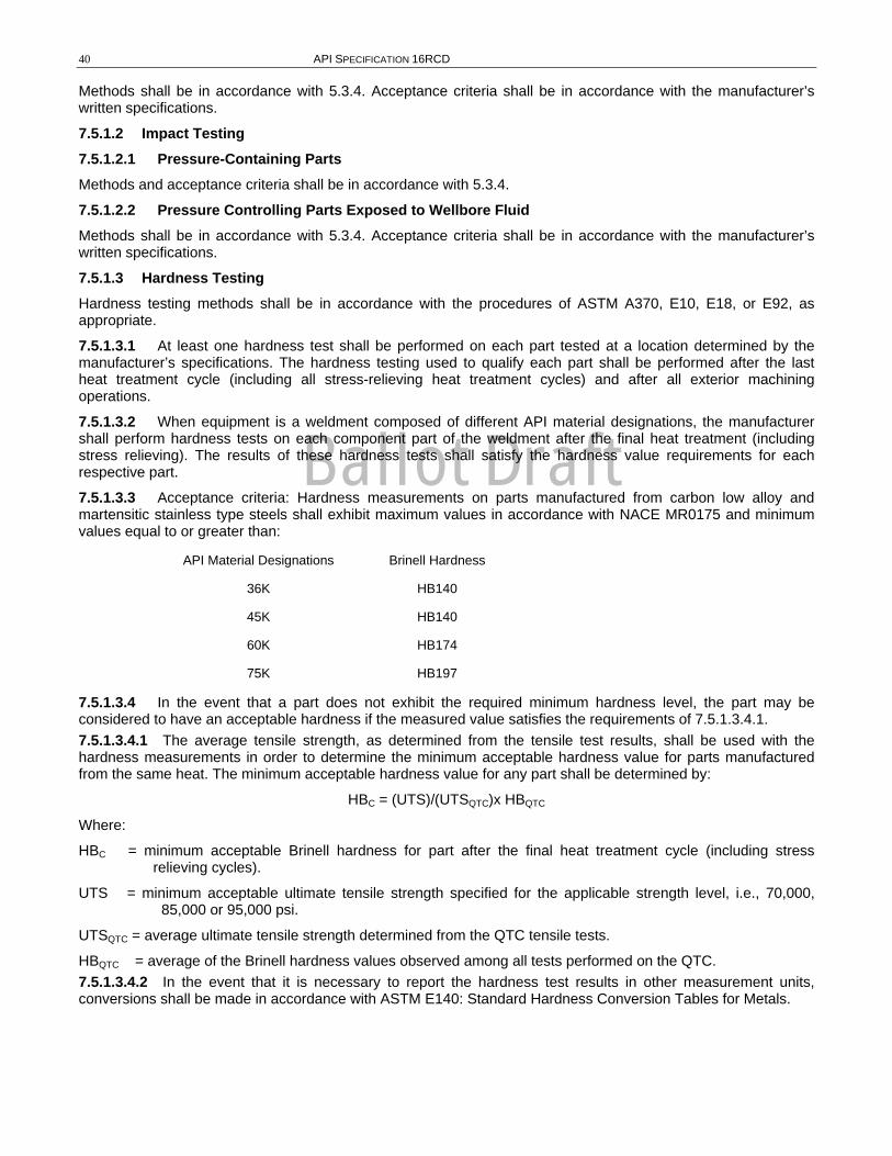
Ballot Draft
40 API SPECIFICATION 16RCD
Methods shall be in accordance with 5.3.4. Acceptance criteria shall be in accordance with the manufacturer’s written specifications.
7.5.1.2 Impact Testing 7.5.1.2.1 Pressure-Containing Parts Methods and acceptance criteria shall be in accordance with 5.3.4.
7.5.1.2.2 Pressure Controlling Parts Exposed to Wellbore Fluid Methods shall be in accordance with 5.3.4. Acceptance criteria shall be in accordance with the manufacturer’s written specifications.
7.5.1.3 Hardness Testing Hardness testing methods shall be in accordance with the procedures of ASTM A370, E10, E18, or E92, as appropriate.
7.5.1.3.1 At least one hardness test shall be performed on each part tested at a location determined by the manufacturer’s specifications. The hardness testing used to qualify each part shall be performed after the last heat treatment cycle (including all stress-relieving heat treatment cycles) and after all exterior machining operations.
7.5.1.3.2 When equipment is a weldment composed of different API material designations, the manufacturer shall perform hardness tests on each component part of the weldment after the final heat treatment (including stress relieving). The results of these hardness tests shall satisfy the hardness value requirements for each respective part.
7.5.1.3.3 Acceptance criteria: Hardness measurements on parts manufactured from carbon low alloy and martensitic stainless type steels shall exhibit maximum values in accordance with NACE MR0175 and minimum values equal to or greater than:
API Material Designations Brinell Hardness
36K HB140
45K HB140
60K HB174
75K HB197
7.5.1.3.4 In the event that a part does not exhibit the required minimum hardness level, the part may be considered to have an acceptable hardness if the measured value satisfies the requirements of 7.5.1.3.4.1. 7.5.1.3.4.1 The average tensile strength, as determined from the tensile test results, shall be used with the hardness measurements in order to determine the minimum acceptable hardness value for parts manufactured from the same heat. The minimum acceptable hardness value for any part shall be determined by:
HBC = (UTS)/(UTSQTC)x HBQTC
Where:
HBC = minimum acceptable Brinell hardness for part after the final heat treatment cycle (including stress relieving cycles).
UTS = minimum acceptable ultimate tensile strength specified for the applicable strength level, i.e., 70,000, 85,000 or 95,000 psi.
UTSQTC = average ultimate tensile strength determined from the QTC tensile tests.
HBQTC = average of the Brinell hardness values observed among all tests performed on the QTC. 7.5.1.3.4.2 In the event that it is necessary to report the hardness test results in other measurement units, conversions shall be made in accordance with ASTM E140: Standard Hardness Conversion Tables for Metals.
Ballot Draft
SPECIFICATION FOR DRILL THROUGH EQUIPMENT – ROTATING CONTROL DEVICES 41
7.5.1.4 Dimensional Verification Critical dimensions as defined by the manufacturer shall be documented for each part and such documentation shall be retained by the manufacturer in accordance with 7.6. The manufacturer shall define and document the extent to which dimensions shall be verified.
7.5.1.5 Traceability Parts and material shall be traceable to the individual heat and heat treatment lot.
7.5.1.5.1 Identification shall be maintained on materials and parts, to facilitate traceability, as required by documented manufacturer requirements.
7.5.1.5.2 Manufacturer documented traceability requirements shall include provisions for maintenance or replacement of identification marks and identification control records.
7.5.1.6 Chemical Analysis 7.5.1.6.1 Sampling Chemical analysis shall be performed on a heat basis.
7.5.1.6.2 Methods Chemical analysis shall be performed in accordance with the manufacturer’s written procedure.
7.5.1.6.3 Acceptance Criteria The chemical composition shall meet the requirements of 5.3.3.
7.5.1.7 Visual Examination 7.5.1.7.1 Sampling Each part shall be visually examined.
7.5.1.7.2 Methods Visual examinations of castings and forgings shall be performed in accordance with the manufacturer’s written specification.
7.5.1.7.3 Acceptance Criteria Acceptance criteria shall be in accordance with manufacturer’s written specifications.
7.5.1.7.4 Non-Well Fluid Wetted and Non-Sealing Surfaces Such surfaces shall be examined in accordance with visual examination methods described in this section.
7.5.1.8 Surface NDE 7.5.1.8.1 General All accessible surfaces of each finished part shall be inspected in accordance with this section. 7.5.1.8.1.1 Surface NDE of Ferromagnetic Materials All accessible well fluid wetted surfaces and all accessible sealing surfaces of each finished part shall be inspected after final heat treatment and after final machining operations by either magnetic particle (MP) or liquid penetrant (LP) methods. 7.5.1.8.1.2 Surface NDE of Non-Ferromagnetic Materials All accessible well fluid wetted surfaces of each finished part shall be inspected after final heat treatment and after final machining operations by LP method.
7.5.1.8.2 Methods 7.5.1.8.2.1 MP examination shall be in accordance with procedures specified in ASTM E709. Prods are not permitted on well fluid wetted surfaces or sealing surfaces. 7.5.1.8.2.2 LP examination shall be in accordance with procedures specified in ASTM E-165.
7.5.1.8.3 Acceptance Criteria for MP and LP
Ballot Draft
42 API SPECIFICATION 16RCD
Note: Inherent indications not associated with a surface rupture (e.g. magnetic permeability variations, non-metallic stringers) are not considered relevant indications. 7.5.1.8.3.1 Acceptance criteria for surfaces other than pressure contact (metal-to-metal) sealing surfaces:
a) No relevant indication with a major dimension equal to or greater than 3/16-inch.
b) No more than ten relevant indications in any continuous 6-square-inch area.
c) Four or more relevant indications in a line separated by less than 1/16-inch (edge to edge) are unacceptable. 7.5.1.8.3.2 Acceptance Criteria for pressure-contact (metal-to-metal) sealing surfaces:
There shall be no relevant indications in the pressure contact (metal-to-metal) sealing surfaces.
7.5.1.9 Weld NDE—General When examination is required herein, essential welding variables and equipment shall be monitored, and completed weldments (a minimum of 1/2-inch of surrounding base metal) and the entire accessible weld shall be examined in accordance with the methods and acceptance criteria of this section.
7.5.1.10 Weld Prep NDE—Visual 7.5.1.10.1 Weld Prep NDE—Surface Preparation Examination 7.5.1.10.1.1 One hundred percent of all surfaces prepared for welding shall be visually examined prior to initiating welding. 7.5.1.10.1.2 Examinations shall include a minimum of 1/2-inch of adjacent base metal on both sides of the weld.
7.5.1.10.2 Weld NDE surface preparation acceptance shall be in accordance with the manufacturer’s written specification.
7.5.1.11 Post-Weld Visual Examination 7.5.1.11.1 All welds shall be examined according to manufacturer’s written specification.
7.5.1.11.2 Any undercut detected by visual examination shall be evaluated in accordance with the manufacturer’s written specification.
7.5.1.11.3 Surface porosity and exposed slag are not permitted on or within 1/8-inch of sealing surfaces.
7.5.1.12 Weld NDE—Surface (Other Than Visual) 7.5.1.12.1 General One hundred percent of all pressure-containing welds, repair, and weld metal overlay welds and repaired fabrication welds shall be examined by either MP or LP methods after all welding, post-weld heat treatment, and machining operations are completed. The examination shall include 1/2-inch of adjacent base material on both sides of the weld.
7.5.1.12.2 Methods Methods and acceptance criteria for MP and LP examinations shall be the same as in 7.5.1.8.2 except:
a Magnetic Particle
1) No relevant linear indications.
2) No rounded indications greater than 1/8-inch for welds whose depth is 5/8-inch or less or 3/16-inch for welds whose depth is greater than 5/8-inch.
b Liquid Penetrant: No rounded indications greater than 1/8-inch for welds whose depth is 5/8-inch or less or 3/16-inch for welds whose depth is greater than 5/8-inch.
7.5.1.12.3 Manufacturers shall not be restricted to these criteria provided they have the means to and determine the acceptable defect size and configuration based on their stress analysis of the product. Results of the analysis shall be documented.
7.5.1.13 Repair Welds 7.5.1.13.1 All repair welds shall be examined using the same methods and acceptance criteria used in examining the base metal (Refer to 7.5.1.8).
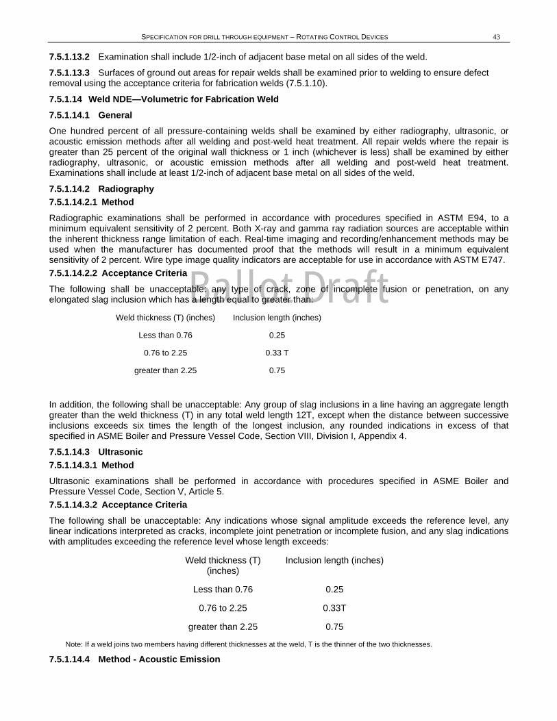
Ballot Draft
SPECIFICATION FOR DRILL THROUGH EQUIPMENT – ROTATING CONTROL DEVICES 43
7.5.1.13.2 Examination shall include 1/2-inch of adjacent base metal on all sides of the weld.
7.5.1.13.3 Surfaces of ground out areas for repair welds shall be examined prior to welding to ensure defect removal using the acceptance criteria for fabrication welds (7.5.1.10).
7.5.1.14 Weld NDE—Volumetric for Fabrication Weld 7.5.1.14.1 General One hundred percent of all pressure-containing welds shall be examined by either radiography, ultrasonic, or acoustic emission methods after all welding and post-weld heat treatment. All repair welds where the repair is greater than 25 percent of the original wall thickness or 1 inch (whichever is less) shall be examined by either radiography, ultrasonic, or acoustic emission methods after all welding and post-weld heat treatment. Examinations shall include at least 1/2-inch of adjacent base metal on all sides of the weld.
7.5.1.14.2 Radiography 7.5.1.14.2.1 Method Radiographic examinations shall be performed in accordance with procedures specified in ASTM E94, to a minimum equivalent sensitivity of 2 percent. Both X-ray and gamma ray radiation sources are acceptable within the inherent thickness range limitation of each. Real-time imaging and recording/enhancement methods may be used when the manufacturer has documented proof that the methods will result in a minimum equivalent sensitivity of 2 percent. Wire type image quality indicators are acceptable for use in accordance with ASTM E747. 7.5.1.14.2.2 Acceptance Criteria The following shall be unacceptable: any type of crack, zone of incomplete fusion or penetration, on any elongated slag inclusion which has a length equal to greater than:
Weld thickness (T) (inches) Inclusion length (inches)
Less than 0.76 0.25
0.76 to 2.25 0.33 T
greater than 2.25 0.75
In addition, the following shall be unacceptable: Any group of slag inclusions in a line having an aggregate length greater than the weld thickness (T) in any total weld length 12T, except when the distance between successive inclusions exceeds six times the length of the longest inclusion, any rounded indications in excess of that specified in ASME Boiler and Pressure Vessel Code, Section VIII, Division I, Appendix 4.
7.5.1.14.3 Ultrasonic 7.5.1.14.3.1 Method Ultrasonic examinations shall be performed in accordance with procedures specified in ASME Boiler and Pressure Vessel Code, Section V, Article 5. 7.5.1.14.3.2 Acceptance Criteria The following shall be unacceptable: Any indications whose signal amplitude exceeds the reference level, any linear indications interpreted as cracks, incomplete joint penetration or incomplete fusion, and any slag indications with amplitudes exceeding the reference level whose length exceeds:
Weld thickness (T) (inches)
Inclusion length (inches)
Less than 0.76 0.25
0.76 to 2.25 0.33T
greater than 2.25 0.75
Note: If a weld joins two members having different thicknesses at the weld, T is the thinner of the two thicknesses.
7.5.1.14.4 Method - Acoustic Emission
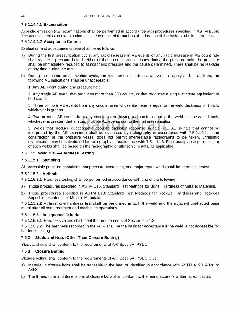
Ballot Draft
44 API SPECIFICATION 16RCD
7.5.1.14.4.1 Examination Acoustic emission (AE) examinations shall be performed in accordance with procedures specified in ASTM E569. The acoustic emission examination shall be conducted throughout the duration of the hydrostatic “in-plant” test. 7.5.1.14.4.2 Acceptance Criteria Evaluation and acceptance criteria shall be as follows:
a) During the first pressurization cycle, any rapid increase in AE events or any rapid increase in AE count rate shall require a pressure hold. If either of these conditions continues during the pressure hold, the pressure shall be immediately reduced to atmospheric pressure and the cause determined. There shall be no leakage at any time during the test.
b) During the second pressurization cycle, the requirements of item a above shall apply and, in addition, the following AE indications shall be unacceptable:
1. Any AE event during any pressure hold.
2. Any single AE event that produces more than 500 counts, or that produces a single attribute equivalent to 500 counts.
3. Three or more AE events from any circular area whose diameter is equal to the weld thickness or 1 inch, whichever is greater.
4. Two or more AE events from any circular area (having a diameter equal to the weld thickness or 1 inch, whichever is greater) that emitted multiple AE events during the first pressurization.
5. Welds that produce questionable acoustic emission response signals (i.e., AE signals that cannot be interpreted by the AE examiner) shall be evaluated by radiography in accordance with 7.5.1.14.2. If the construction of the pressure vessel does not permit interpretable radiographs to be taken, ultrasonic examination may be substituted for radiography in accordance with 7.5.1.14.3. Final acceptance (or rejection) of such welds shall be based on the radiographic or ultrasonic results, as applicable.
7.5.1.15 Weld NDE—Hardness Testing 7.5.1.15.1 Sampling All accessible pressure-containing, nonpressure-containing, and major repair welds shall be hardness tested.
7.5.1.15.2 Methods 7.5.1.15.2.1 Hardness testing shall be performed in accordance with one of the following:
a) Those procedures specified in ASTM E10, Standard Test Methods for Brinell Hardness of Metallic Materials.
b) Those procedures specified in ASTM E18: Standard Test Methods for Rockwell Hardness and Rockwell Superficial Hardness of Metallic Materials.
7.5.1.15.2.2 At least one hardness test shall be performed in both the weld and the adjacent unaffected base metal after all heat treatment and machining operations.
7.5.1.15.3 Acceptance Criteria 7.5.1.15.3.1 Hardness values shall meet the requirements of Section 7.5.1.3. 7.5.1.15.3.2 The hardness recorded in the PQR shall be the basis for acceptance if the weld is not accessible for hardness testing.
7.5.2 Studs and Nuts (Other Than Closure Bolting) Studs and nuts shall conform to the requirements of API Spec 6A, PSL 1.
7.5.3 Closure Bolting Closure bolting shall conform to the requirements of API Spec 6A, PSL 1, plus:
a) Material in closure bolts shall be traceable to the heat or identified in accordance with ASTM A193, A320 or A453.
b) The thread form and dimensions of closure bolts shall conform to the manufacturer’s written specification.
Ballot Draft
SPECIFICATION FOR DRILL THROUGH EQUIPMENT – ROTATING CONTROL DEVICES 45
7.5.4 Ring Gaskets Ring gaskets shall conform to the requirements of API Spec 6A, PSL 1.
7.5.5 Non-Metallic Sealing Materials and Molded Sealing Assemblies 7.5.5.1 RCD Packers and Seals 7.5.5.1.1 Testing of Material Testing of each batch shall be in accordance with ASTM procedures. If a suitable ASTM procedure cannot be applied, the manufacturer shall provide a written procedure for testing. Characteristics shall be defined by measurements of physical properties.
Mechanical property data shall include the following:
a) Hardness data in accordance with ASTM D1415 or D2240.
b) Tensile data in accordance with ASTM D1414 or D412.
c) Elongation data in accordance with ASTM D1414 or D412.
d) Modulus data in accordance with ASTM D1414 or D412.
7.5.5.1.2 Acceptance Criteria Acceptance shall be in accordance with manufacturer’s written specifications.
7.5.5.2 Metallic Inserts in Molded Assemblies 7.5.5.2.1 Dimensional Verification 7.5.5.2.1.1 Sampling Sampling shall be in accordance with manufacturer’s written requirements or MIL STD 105D, Level II, 4.0 AQL. 7.5.5.2.1.2 Methods All methods shall be in accordance with manufacturer’s written requirements. 7.5.5.2.1.3 Acceptance Criteria Acceptance shall be in accordance with manufacturer’s written specifications.
7.5.5.2.2 Hardness Testing 7.5.5.2.2.1 Sampling Sampling shall be in accordance with manufacturer’s written requirements or MIL STD-105D, Level II, 4.0 AQL. 7.5.5.2.2.2 Methods A minimum of one hardness test shall be performed in accordance with procedures specified in ASTM E18 or E10. 7.5.5.2.2.3 Acceptance Criteria Acceptance shall be in accordance with manufacturer’s written requirements and NACE MR0175.
7.5.5.2.3 Welding NDE Welding NDE shall be in accordance with manufacturer’s written specifications.
7.5.6 All Other Drill through RCD Equipment not Covered in 7.5.1 Through 7.5.5 All quality control requirements shall be documented in the manufacturer’s written specifications.
7.5.7 Assembled Equipment 7.5.7.1 General The quality control requirements for assembled equipment shall include drift tests, pressure tests, rotating torque tests (if applicable) and hydraulic operating system tests.
Ballot Draft
46 API SPECIFICATION 16RCD
7.5.7.2 Serialization Serialization is required on all assembled equipment and shall be done in accordance with the manufacturer’s written specification.
7.5.7.3 Traceability Record Report A report shall be prepared in which all serialized and individual heat traceable parts are listed as traceable to the assembly (e.g., assembly part number, serial number).
7.5.7.4 Drift Test A drift test is required on RCDs.
7.5.7.4.1 Method Pass a drift mandrel through the bore of the assembly after all pressure testing. 7.5.7.4.1.1 Drift mandrel diameter shall be 0.020-0.030 inches less than the manufacturers specified size designation of the bore of the bearing assembly and RCD body. 7.5.7.4.1.2 Drift mandrel gage length shall be at least 2 inches longer than any cavity that intersects the bore, but not less than 12 inches.
7.5.7.4.2 Acceptance The drift mandrel shall pass through without being forced.
7.5.7.5 Pressure Test Equipment A data acquisition system shall be used on all hydrostatic tests and on hydraulic control system tests. Pressure gauges used shall be as described in 7.2.3. The record shall identify the recording device and shall be dated and signed.
7.5.7.6 Hydrostatic Proof Testing 7.5.7.6.1 General All RCDs shall be subjected to a hydrostatic proof test prior to shipment from the manufacturer’s facility. Water or water with additives shall be used as the testing fluid. Any additives shall be documented in the test records.
7.5.7.6.2 In-Plant Hydrostatic body or Shell Test 7.5.7.6.2.1 General RCDs shall be tested with its sealing mechanisms in the open position, if applicable. 7.5.7.6.2.2 Test Pressure The hydrostatic proof or shell test pressure shall be determined by the rated static pressure for the equipment. Hydrostatic proof test pressures shall be 1.5 X static pressure rating
7.5.7.6.3 Rotating Torque Test Following all pressure tests a rotating torque test shall be undertaken to confirm that the torque is within Manufacturers specification.
7.5.7.6.4 Hydraulic Operating Chamber Test 7.5.7.6.4.1 General The hydraulic operating system test shall be tested on each assembled RCD. 7.5.7.6.4.2 Test Pressure The hydraulic operating chamber shall be tested at a minimum test pressure equal to 1.5 times the operating chamber’s rated working pressure.
7.5.7.6.5 Procedure The hydrostatic proof test shall consist of three steps:
a) The initial pressure-holding period of not less than 3 minutes.
b) The reduction of the pressure to zero.
Ballot Draft
SPECIFICATION FOR DRILL THROUGH EQUIPMENT – ROTATING CONTROL DEVICES 47
c) The second pressure-holding period of not less than 15 minutes.
The timing of the test shall not start until the test pressure has been stabilized within the manufacturer’s specified range and the external surfaces have been thoroughly dried.
7.5.7.6.6 Acceptance Criterion The acceptance criterion is that there shall be no leakage.
7.5.7.7 Closed RCD Test 7.5.7.7.1 General 7.5.7.7.1.1 Each assembled RCD shall be subjected to a closed test after the hydrostatic proof test. The hydraulic operating system pressure used shall be equal to or less than the manufacturer’s specified operating pressure. The test fluids used for all closed tests shall meet the requirements of 7.5.7.6.1. 7.5.7.7.1.2 The timing of all closed RCD tests shall not start until the test pressure has stabilized. 7.5.7.7.1.3 Closed RCD tests shall be performed at low and high pressure with the low pressure tests always preceding the high pressure test.
7.5.7.7.1.3.1 Low Pressure Test A pressure of 50 to 120 psi shall be applied and held below the closed RCD packing unit for a time period of not less than 10 minutes after stabilization.
7.5.7.7.1.3.2 High Pressure Test A pressure at least equal to the rated static pressure of the RCD shall be applied and held below the closed RCD packing unit for a time period of not less than 10 minutes after stabilization. (see exception for RCD packing units in 7.5.7.7.2.2.
7.5.7.7.1.3.3 Acceptance Criterion The acceptance criterion is that there shall be no visible leakage.
7.5.7.7.2 RCD Packing Unit Test Requirements RCD packing units shall be tested in two stages. 7.5.7.7.2.1 Stage one This test shall require closing on the appropriate size drill pipe as specified by the manufacturer: 7.5.7.7.2.2 Stage Two If manufacturer specifies CSO, this test shall require closing without drill pipe in the RCD, i.e., on the open hole. The high pressure test shall be as specified in 7.5.7.7.1.3.2 except as a minimum it shall be performed at a pressure equal to half the manufacturers specified working pressure.
7.6 QUALITY CONTROL RECORDS REQUIREMENTS 7.6.1 General The quality control records required by this specification are those documents and records necessary to substantiate that all materials and equipment made to this specification do conform to the specified requirements.
7.6.1.1 NACE Records Requirements Records required to substantiate conformance of equipment to NACE requirements shall be in addition to those described in other sections of this document unless the records required by this specification also satisfy the MR0175 requirements.
7.6.1.2 Records Control 7.6.1.2.1 Records required by this specification shall be legible, identifiable, retrievable and protected from damage, deterioration, or loss.
7.6.1.2.2 Records required by this specification shall be retained by the manufacturer for a minimum of ten years following the date of manufacture as marked on the equipment associated with the records.
Ballot Draft
48 API SPECIFICATION 16RCD
7.6.1.2.3 The manufacturer shall document and retain all records for each batch of raw material used in the manufacture of RCD packers and seals. Records shall be retained for a minimum period of five years.
7.6.1.2.4 All records required by this specification shall be signed and dated. Computer-stored records shall contain originator’s personal code.
7.6.2 Records to Be Maintained by Manufacturer
7.6.2.1 The manufacturer shall retain all documents and records as required in Sections 4, 5, 6, and 7.
7.6.2.2 For those parts or components covered in Section 7.5.1: a) Weld procedure qualification record. b) Welder qualification record. c) Material test records:
1. Chemical analysis. 2. Tensile tests (QTC). 3. Impact tests (QTC, as required). 4. Hardness tests (QTC).
d) NDE personnel qualification records. e) NDE records:
1. Surface NDE records. 2. Full penetration fabrication. 3. Weld volumetric NDE records. 4. Repair weld NDE records.
f) Hardness test records. g) Welding process records:
1. Welder identification. 2. Weld procedures. 3. Filler materials. 4. Post-Weld heat treatments.
h) Heat treatment records: 1. Actual temperature. 2. Actual times at temperature.
i) Volumetric NDE records. j) Hydrostatic pressure test records. k) Critical dimensions as defined by the manufacturer.
7.6.2.3 Closure Bolting The manufacturer shall retain individual heat traceability records for closure bolting, as required.
7.6.2.4 Non-Metallic Sealing Materials and Molded Sealing Assemblies The manufacturer shall retain a certification of compliance for non-metallic sealing materials and molded sealing assemblies to manufacturer’s written requirements.
7.6.3 Records to Be Furnished to Original Purchaser upon Product Delivery A manufacturer’s certificate of compliance stating that equipment conforms to the current edition of API Spec 16RCD shall be furnished to the original purchaser upon product delivery.
8 MARKING REQUIREMENTS 8.1 GENERAL All equipment, as listed in Section 1.2.1, manufactured in accordance with this specification shall be marked in accordance with the procedure and requirements of this section and Table 10.
Ballot Draft
SPECIFICATION FOR DRILL THROUGH EQUIPMENT – ROTATING CONTROL DEVICES 49
8.2 TYPES OF IDENTIFICATION STAMPING 8.2.1 Metallic components 8.2.1.1 Low Stress Area Marking For identification on low stress areas (such as nameplates, outside diameters of flanges, etc.), the use of sharp “V” stamping is acceptable.
8.2.1.2 High Stress Area Marking For identification on high stress areas, dot, vibration, or round “V” stamping is acceptable. Sharp “V” stamping is allowed in high stress areas only if subsequent stress relieving is performed to the component.
8.2.1.3 Weld Metal Overlays When equipment has weld metal overlaid ring grooves, shall be marked in accordance with API Spec 6A.
8.2.1.4 Monogram For API monogrammed equipment, the API Monogram shall be stamped on the product after the product description code (PDC) or alphanumeric code, followed by “16RCD”, the edition of Spec 16RCD to which the equipment was manufactured, and the manufacturer’s license number. For information on API Licensing, contact the API Exploration and Production Department.
8.2.1.5 Static Pressure Rating Identification The manufacturer’s specified static pressure rating shall be clearly and permanently marked by means of welding, milling, casting, grinding or forging in an easily accessible and readable area on the RCD body. Cold stamping does not meet this requirement.
8.2.2 Non-Metallic Components 8.2.2.1 Wellbore Non-Metallic Components For identification of wellbore non-metallic components, such as RCD-type RCD packers and seals, the manufacturer shall have a written procedure for affixing the required codification to the product or its package.
8.2.2.2 Non-Wellbore Non-Metallic Components Identification of non-wellbore non-metallic components, such as elastomeric seals used in RCD type RCD actuation systems shall be in accordance with the manufacturer’s written specification.
8.3 SPECIFIC CODIFICATION REQUIREMENTS OF EQUIPMENT 8.3.1 Gaskets Ring gaskets shall be marked in accordance with API Spec 6A.
8.3.2 Studs and Nuts Studs and nuts shall be marked in accordance with API Spec 6A.
8.3.3 Closure Bolting Closure bolting shall be marked in accordance with the manufacturer’s written specification.
8.3.4 Packers and Seals 8.3.4.1 Wellbore Non-Metallic Components Wellbore non-metallic components, as described in Section 8.2.2.1, shall be marked with an alpha-numeric codification system in the sequence denoted below. The meaning of the digits that make up this alpha-numeric number is described below. In addition, the manufacturer’s part number shall be marked on the component.
AA BBBB CCCC DDDD EE
Compound Hardness (durometer) AA
Compound (see Table 9) BBBB
Date of manufacture (see 8.3.4.2) CCCC
Ballot Draft
50 API SPECIFICATION 16RCD
Lot/Serial Number (per manufacturer’s specs.) DDDD
Temperature Class (see 8.3.4.3) EE
Table 9 - Elastomer Compound Marking Code
Common Name Chemical Name ASTM Code D1418
Butyl Isobutylene-isoprene IIR
Epichlorohydrin CO
Epichlorohydrin-ethylene oxide
ECO
Kel-F Chloro fluoro elastomer
CFM
Hypalon Chlorosulfonated polyethylene
CSM
EPR Ethylene-propylene copolymer
EPM
EPT Ethylene-propylene terpolymer
EPDM
Viton Fluorocarbon FKM
Natural Polyisoprene NR
Isoprene
Natural or synthetic Polisoprene IR
Nitrile Butadiene-acrylonitrile NBR
Acrylic Polyacrylic ACM
Diene Polybutadiene BR
Neoprene Polychloroprene CR
Vistanex Polyisobutylene IM
Thiokol Polysulfide —
Silicone Polysiloxanes Si
SBR(GR-S) Styrene-butadiene SBR
Urethane Diisocyanates —
Note: Compounds which are not listed above shall be marked “N/A.”
8.3.4.2 Date of Manufacture The date of manufacture shall consist of the month, in numerical form and the last two digits of the year (eg. October 1996 would be coded 1096 for code CCCC).
8.3.4.3 Temperature Class The temperature class shall be as follows:
Lower Limit (first digit) Upper Limit (second digit)
A –15ºF A 180ºF
B 0ºF B 200ºF
C 10ºF C 220ºF
Ballot Draft
SPECIFICATION FOR DRILL THROUGH EQUIPMENT – ROTATING CONTROL DEVICES 51
D 20ºF D 250ºF
E 30ºF E 300ºF
F 40ºF F 350ºF
G other G other
X (see note) X (see note)
Note: These components may carry a temperature class of 40º to 180ºF without performing temperature verification testing provided they are marked as temperature class “XX” in accordance with this section.
(Example: “EB” has a temperature class of 30º to 200ºF.)
9 STORING AND SHIPPING 9.1 STORING FOR PERIODS OF GREATER THAN 30 DAYS 9.1.1 Draining after Testing All equipment shall be drained after testing and prior to storage.
9.1.2 Rust Prevention Prior to storage, parts and equipment shall have exposed metallic surfaces protected with a rust preventative, which will not become fluid a temperatures below 125ºF.
9.1.3 Connection Surface Protection All connection faces and ring gasket grooves shall be protected with durable covers.
9.1.4 Hydraulic Operating System The hydraulic operating system shall be flushed with a non-freezing, corrosion-inhibiting fluid in accordance with the manufacturer’s written procedures. Ports shall be plugged prior to storing.
9.1.5 Elastomeric Seals Elastomeric seals shall be stored in accordance with the manufacturer’s written procedures.
9.1.6 Ring Gaskets Loose ring gaskets shall be wrapped or boxed for storage and shipping.
9.2 SHIPPING All equipment is to be shipped in accordance with the manufacturer’s written procedures.
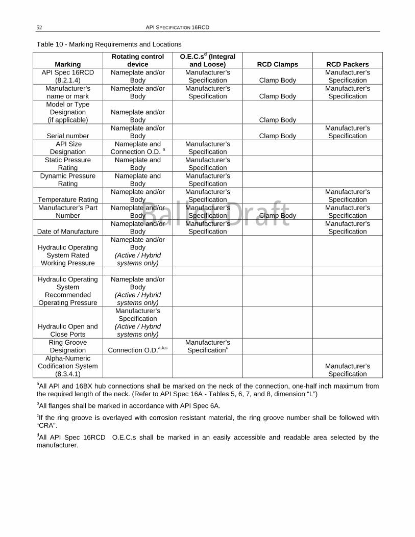
Ballot Draft
52 API SPECIFICATION 16RCD
Table 10 - Marking Requirements and Locations
Marking Rotating control
device O.E.C.sd (Integral
and Loose) RCD Clamps RCD Packers API Spec 16RCD
(8.2.1.4) Nameplate and/or
Body Manufacturer’s Specification Clamp Body
Manufacturer’s Specification
Manufacturer’s name or mark
Nameplate and/or Body
Manufacturer’s Specification Clamp Body
Manufacturer’s Specification
Model or Type Designation
(if applicable) Nameplate and/or
Body Clamp Body
Serial number Nameplate and/or
Body Clamp Body Manufacturer’s Specification
API Size Designation
Nameplate and Connection O.D. a
Manufacturer’s Specification
Static Pressure Rating
Nameplate and Body
Manufacturer’s Specification
Dynamic Pressure Rating
Nameplate and Body
Manufacturer’s Specification
Temperature Rating Nameplate and/or
Body Manufacturer’s Specification
Manufacturer’s Specification
Manufacturer’s Part Number
Nameplate and/or Body
Manufacturer’s Specification Clamp Body
Manufacturer’s Specification
Date of Manufacture Nameplate and/or
Body Manufacturer’s Specification
Manufacturer’s Specification
Hydraulic Operating System Rated
Working Pressure
Nameplate and/or Body
(Active / Hybrid systems only)
Hydraulic Operating
System Recommended
Operating Pressure
Nameplate and/or Body
(Active / Hybrid systems only)
Hydraulic Open and Close Ports
Manufacturer’s Specification
(Active / Hybrid systems only)
Ring Groove Designation Connection O.D.a,b,c
Manufacturer’s Specificationc
Alpha-Numeric Codification System
(8.3.4.1) Manufacturer’s Specification
aAll API and 16BX hub connections shall be marked on the neck of the connection, one-half inch maximum from the required length of the neck. (Refer to API Spec 16A - Tables 5, 6, 7, and 8, dimension “L”) bAll flanges shall be marked in accordance with API Spec 6A. cIf the ring groove is overlayed with corrosion resistant material, the ring groove number shall be followed with “CRA”. dAll API Spec 16RCD O.E.C.s shall be marked in an easily accessible and readable area selected by the manufacturer.
Ballot Draft
SPECIFICATION FOR DRILL THROUGH EQUIPMENT – ROTATING CONTROL DEVICES 53
APPENDIX A - METRIC CONVERSIONS AND FRACTION-TO-DECIMAL EQUIVALENTS English units are in all cases preferential (except for test coupons, which are 10 mm x 10 mm) and shall be the standard in this specification. These factors are taken from API publication 2564.
Length 1 inch (in.) = 25.4 millimeters (mm), exactly
Pressure 1 pound per square inch (psi) = 0.06894757 Bar
Strength or Stress 1 pound per square inch (psi) = 0.006894757 Megapascals (mPa)
Impact Energy 1 foot-pound (ft-lb) = 1.355818 Joules (J)
Torque 1 foot-pound (ft-lb) = 1.355818 newton-meters (N-m)
Temperature To convert degrees Fahrenheit (F) to degrees Celsius (C): (C = 5/9(ºF-32)
Mass 1 pound-mass (lbm) = 0.4535924 kilograms (kg)
Force 1 pound-force = 4.44823 newton (N)
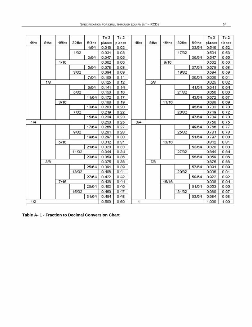
Ballot Draft
SPECIFICATION FOR DRILL THROUGH EQUIPMENT – RCDS 54
Table A- 1 - Fraction to Decimal Conversion Chart
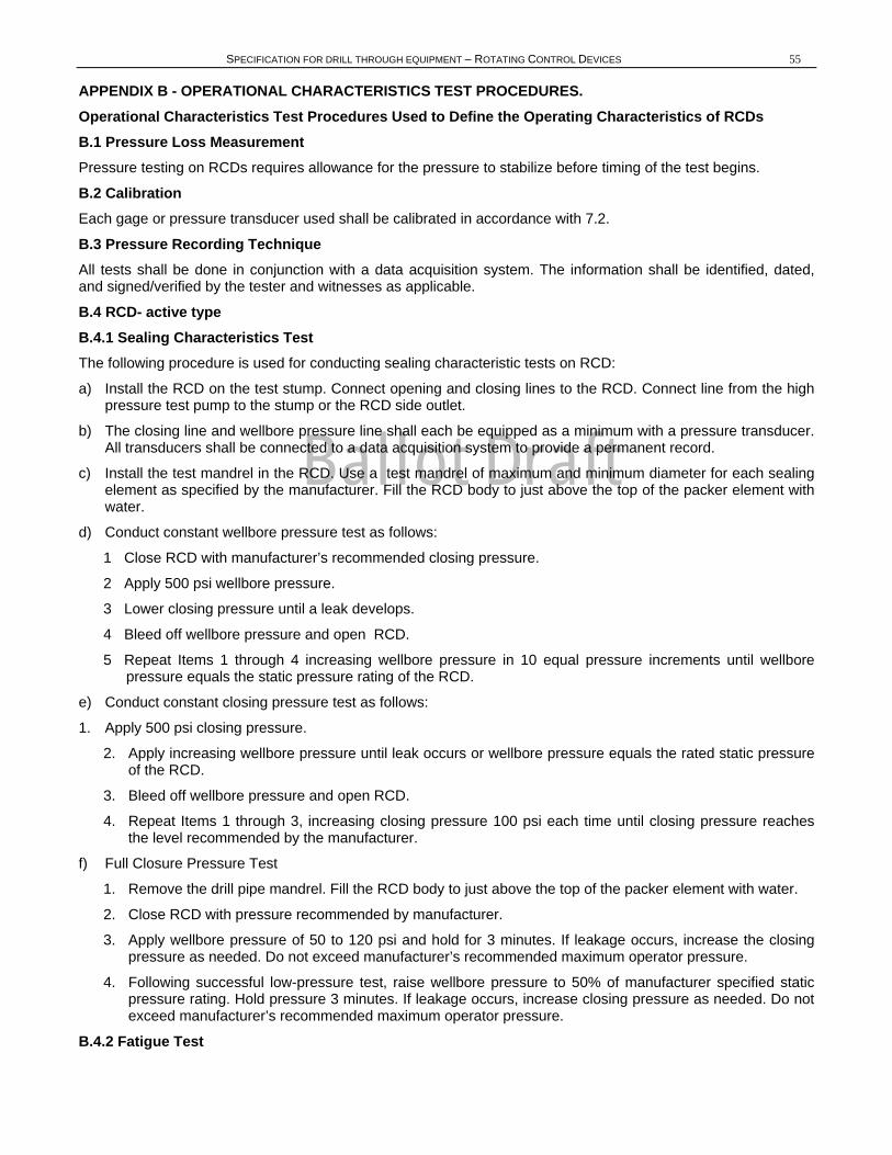
Ballot Draft
SPECIFICATION FOR DRILL THROUGH EQUIPMENT – ROTATING CONTROL DEVICES 55
APPENDIX B - OPERATIONAL CHARACTERISTICS TEST PROCEDURES. Operational Characteristics Test Procedures Used to Define the Operating Characteristics of RCDs B.1 Pressure Loss Measurement Pressure testing on RCDs requires allowance for the pressure to stabilize before timing of the test begins.
B.2 Calibration Each gage or pressure transducer used shall be calibrated in accordance with 7.2.
B.3 Pressure Recording Technique All tests shall be done in conjunction with a data acquisition system. The information shall be identified, dated, and signed/verified by the tester and witnesses as applicable.
B.4 RCD- active type B.4.1 Sealing Characteristics Test The following procedure is used for conducting sealing characteristic tests on RCD:
a) Install the RCD on the test stump. Connect opening and closing lines to the RCD. Connect line from the high pressure test pump to the stump or the RCD side outlet.
b) The closing line and wellbore pressure line shall each be equipped as a minimum with a pressure transducer. All transducers shall be connected to a data acquisition system to provide a permanent record.
c) Install the test mandrel in the RCD. Use a test mandrel of maximum and minimum diameter for each sealing element as specified by the manufacturer. Fill the RCD body to just above the top of the packer element with water.
d) Conduct constant wellbore pressure test as follows:
1 Close RCD with manufacturer’s recommended closing pressure.
2 Apply 500 psi wellbore pressure.
3 Lower closing pressure until a leak develops.
4 Bleed off wellbore pressure and open RCD.
5 Repeat Items 1 through 4 increasing wellbore pressure in 10 equal pressure increments until wellbore pressure equals the static pressure rating of the RCD.
e) Conduct constant closing pressure test as follows:
1. Apply 500 psi closing pressure.
2. Apply increasing wellbore pressure until leak occurs or wellbore pressure equals the rated static pressure of the RCD.
3. Bleed off wellbore pressure and open RCD.
4. Repeat Items 1 through 3, increasing closing pressure 100 psi each time until closing pressure reaches the level recommended by the manufacturer.
f) Full Closure Pressure Test
1. Remove the drill pipe mandrel. Fill the RCD body to just above the top of the packer element with water.
2. Close RCD with pressure recommended by manufacturer.
3. Apply wellbore pressure of 50 to 120 psi and hold for 3 minutes. If leakage occurs, increase the closing pressure as needed. Do not exceed manufacturer’s recommended maximum operator pressure.
4. Following successful low-pressure test, raise wellbore pressure to 50% of manufacturer specified static pressure rating. Hold pressure 3 minutes. If leakage occurs, increase closing pressure as needed. Do not exceed manufacturer’s recommended maximum operator pressure.
B.4.2 Fatigue Test
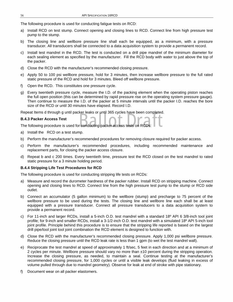
Ballot Draft
56 API SPECIFICATION 16RCD
The following procedure is used for conducting fatigue tests on RCD:
a) Install RCD on test stump. Connect opening and closing lines to RCD. Connect line from high pressure test pump to the stump.
b) The closing line and wellbore pressure line shall each be equipped, as a minimum, with a pressure transducer. All transducers shall be connected to a data acquisition system to provide a permanent record.
c) Install test mandrel in the RCD. The test is conducted on a drill pipe mandrel of the minimum diameter for each sealing element as specified by the manufacturer. Fill the RCD body with water to just above the top of the packer.
d) Close the RCD with the manufacturer’s recommended closing pressure.
e) Apply 50 to 100 psi wellbore pressure, hold for 3 minutes, then increase wellbore pressure to the full rated static pressure of the RCD and hold for 3 minutes. Bleed off wellbore pressure.
f) Open the RCD. This constitutes one pressure cycle.
g) Every twentieth pressure cycle, measure the I.D. of the packing element when the operating piston reaches the full open position (this can be determined by rapid pressure rise on the operating system pressure gauge). Then continue to measure the I.D. of the packer at 5 minute intervals until the packer I.D. reaches the bore size of the RCD or until 30 minutes have elapsed. Record I.D.
Repeat Items d through g until packer leaks or until 365 cycles have been completed.
B.4.3 Packer Access Test The following procedure is used for conducting packer access tests on RCDs:
a) Install the RCD on a test stump.
b) Perform the manufacturer’s recommended procedures for removing closure required for packer access.
c) Perform the manufacturer’s recommended procedures, including recommended maintenance and replacement parts, for closing the packer access closure.
d) Repeat b and c 200 times. Every twentieth time, pressure test the RCD closed on the test mandrel to rated static pressure for a 3 minute holding period.
B.4.4 Stripping Life Test Procedures for RCD The following procedure is used for conducting stripping life tests on RCDs:
a) Measure and record the durometer hardness of the packer rubber. Install RCD on stripping machine. Connect opening and closing lines to RCD. Connect line from the high pressure test pump to the stump or RCD side outlet.
b) Connect an accumulator (5 gallon minimum) to the wellbore (stump) and precharge to 75 percent of the wellbore pressure to be used during the tests. The closing line and wellbore line each shall be at least equipped with a pressure transducer. Connect all pressure transducers to a data acquisition system to provide a permanent record.
c) For 11-inch and larger RCDs, install a 5-inch O.D. test mandrel with a standard 18º API 6 3/8-inch tool joint profile; for 9-inch and smaller RCDs, install a 3-1/2-inch O.D. test mandrel with a simulated 18º API 5-inch tool joint profile. Principle behind this procedure is to ensure that the stripping life reported is based on the largest drill pipe/tool joint tool joint combination the RCD element is designed to function with.
d) Close the RCD with the manufacturer’s recommended closing pressure. Apply 1,000 psi wellbore pressure. Reduce the closing pressure until the RCD leak rate is less than 1 gpm (to wet the test mandrel wall).
e) Reciprocate the test mandrel at speed of approximately 1 ft/sec, 5 feet in each direction and at a minimum of 2 cycles per minute. Wellbore pressure should vary no more than ±10 percent during the stripping operation. Increase the closing pressure, as needed, to maintain a seal. Continue testing at the manufacturer’s recommended closing pressure, for 1,000 cycles or until a visible leak develops (fluid leaking in excess of volume pulled through due to mandrel geometry). Observe for leak at end of stroke with pipe stationary.
f) Document wear on all packer elastomers.
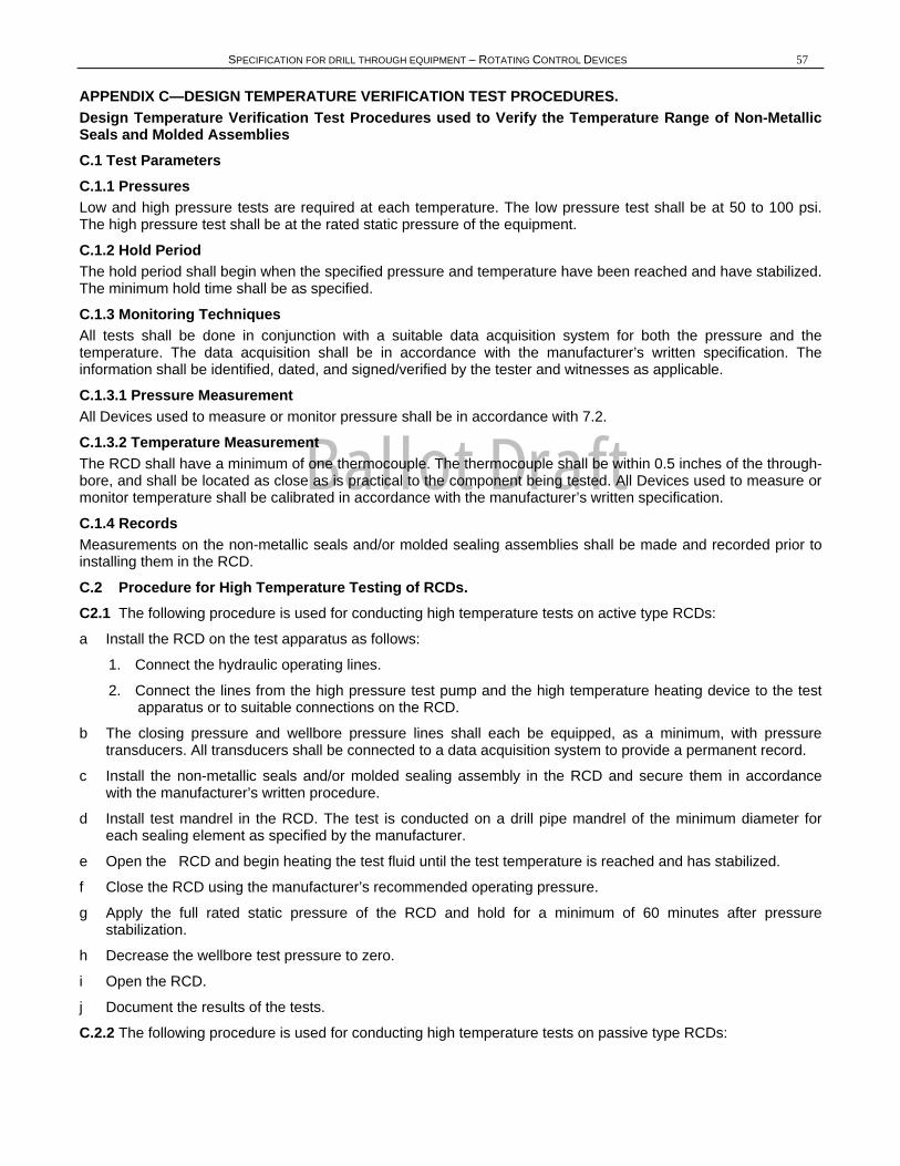
Ballot Draft
SPECIFICATION FOR DRILL THROUGH EQUIPMENT – ROTATING CONTROL DEVICES 57
APPENDIX C—DESIGN TEMPERATURE VERIFICATION TEST PROCEDURES. Design Temperature Verification Test Procedures used to Verify the Temperature Range of Non-Metallic Seals and Molded Assemblies C.1 Test Parameters C.1.1 Pressures Low and high pressure tests are required at each temperature. The low pressure test shall be at 50 to 100 psi. The high pressure test shall be at the rated static pressure of the equipment.
C.1.2 Hold Period The hold period shall begin when the specified pressure and temperature have been reached and have stabilized. The minimum hold time shall be as specified.
C.1.3 Monitoring Techniques All tests shall be done in conjunction with a suitable data acquisition system for both the pressure and the temperature. The data acquisition shall be in accordance with the manufacturer’s written specification. The information shall be identified, dated, and signed/verified by the tester and witnesses as applicable.
C.1.3.1 Pressure Measurement All Devices used to measure or monitor pressure shall be in accordance with 7.2.
C.1.3.2 Temperature Measurement The RCD shall have a minimum of one thermocouple. The thermocouple shall be within 0.5 inches of the through-bore, and shall be located as close as is practical to the component being tested. All Devices used to measure or monitor temperature shall be calibrated in accordance with the manufacturer’s written specification.
C.1.4 Records Measurements on the non-metallic seals and/or molded sealing assemblies shall be made and recorded prior to installing them in the RCD.
C.2 Procedure for High Temperature Testing of RCDs. C2.1 The following procedure is used for conducting high temperature tests on active type RCDs:
a Install the RCD on the test apparatus as follows:
1. Connect the hydraulic operating lines.
2. Connect the lines from the high pressure test pump and the high temperature heating device to the test apparatus or to suitable connections on the RCD.
b The closing pressure and wellbore pressure lines shall each be equipped, as a minimum, with pressure transducers. All transducers shall be connected to a data acquisition system to provide a permanent record.
c Install the non-metallic seals and/or molded sealing assembly in the RCD and secure them in accordance with the manufacturer’s written procedure.
d Install test mandrel in the RCD. The test is conducted on a drill pipe mandrel of the minimum diameter for each sealing element as specified by the manufacturer.
e Open the RCD and begin heating the test fluid until the test temperature is reached and has stabilized.
f Close the RCD using the manufacturer’s recommended operating pressure.
g Apply the full rated static pressure of the RCD and hold for a minimum of 60 minutes after pressure stabilization.
h Decrease the wellbore test pressure to zero.
i Open the RCD.
j Document the results of the tests.
C.2.2 The following procedure is used for conducting high temperature tests on passive type RCDs:
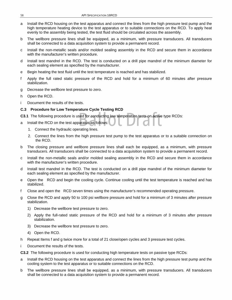
Ballot Draft
58 API SPECIFICATION 16RCD
a Install the RCD housing on the test apparatus and connect the lines from the high pressure test pump and the high temperature heating device to the test apparatus or to suitable connections on the RCD. To apply heat evenly to the assembly being tested, the test fluid should be circulated across the assembly.
b The wellbore pressure lines shall be equipped, as a minimum, with pressure transducers. All transducers shall be connected to a data acquisition system to provide a permanent record.
c Install the non-metallic seals and/or molded sealing assembly in the RCD and secure them in accordance with the manufacturer’s written procedure.
d Install test mandrel in the RCD. The test is conducted on a drill pipe mandrel of the minimum diameter for each sealing element as specified by the manufacturer.
e Begin heating the test fluid until the test temperature is reached and has stabilized.
f Apply the full rated static pressure of the RCD and hold for a minimum of 60 minutes after pressure stabilization.
g Decrease the wellbore test pressure to zero.
h Open the RCD.
i Document the results of the tests.
C.3 Procedure for Low Temperature Cycle Testing RCD C3.1 The following procedure is used for conducting low temperature tests on active type RCDs:
a Install the RCD on the test apparatus as follows:
1. Connect the hydraulic operating lines.
2. Connect the lines from the high pressure test pump to the test apparatus or to a suitable connection on the RCD.
b The closing pressure and wellbore pressure lines shall each be equipped, as a minimum, with pressure transducers. All transducers shall be connected to a data acquisition system to provide a permanent record.
c Install the non-metallic seals and/or molded sealing assembly in the RCD and secure them in accordance with the manufacturer’s written procedure.
d Install test mandrel in the RCD. The test is conducted on a drill pipe mandrel of the minimum diameter for each sealing element as specified by the manufacturer.
e Open the RCD and begin the cooling cycle. Continue cooling until the test temperature is reached and has stabilized.
f Close and open the RCD seven times using the manufacturer’s recommended operating pressure.
g Close the RCD and apply 50 to 100 psi wellbore pressure and hold for a minimum of 3 minutes after pressure stabilization.
1) Decrease the wellbore test pressure to zero.
2) Apply the full-rated static pressure of the RCD and hold for a minimum of 3 minutes after pressure stabilization.
3) Decrease the wellbore test pressure to zero.
4) Open the RCD.
h Repeat Items f and g twice more for a total of 21 close/open cycles and 3 pressure test cycles.
i Document the results of the tests.
C3.2 The following procedure is used for conducting high temperature tests on passive type RCDs:
a Install the RCD housing on the test apparatus and connect the lines from the high pressure test pump and the cooling system to the test apparatus or to suitable connections on the RCD.
b The wellbore pressure lines shall be equipped, as a minimum, with pressure transducers. All transducers shall be connected to a data acquisition system to provide a permanent record.
Ballot Draft
SPECIFICATION FOR DRILL THROUGH EQUIPMENT – ROTATING CONTROL DEVICES 59
c Install the non-metallic seals and/or molded sealing assembly in the RCD and secure them in accordance with the manufacturer’s written procedure.
d Install test mandrel in the RCD. The test is conducted on a tapered mandrel designed to model the minimum drill pipe diameter and the maximum tool joint OD for each sealing element as specified by the manufacturer.
e Begin the cooling cycle. Continue cooling until the test temperature is reached and has stabilized.
f Stroke the test mandrel through the RCD seven times ensuring maximum stretch and contraction of the RCD packer on each stroke.
g Position the drill pipe portion of the test mandrel in the RCD packer and apply 50 to 100 psi wellbore pressure and hold for a minimum of 3 minutes after pressure stabilization.
1) Decrease the wellbore test pressure to zero.
2) Apply the full-rated static pressure of the RCD and hold for a minimum of 3 minutes after pressure stabilization.
3) Decrease the wellbore test pressure to zero.
h Repeat Items f and g twice more for a total of 21 stretch/contract cycles and 3 pressure test cycles.
i Document the results of the tests.
C.4 High/ Low Temperature Cycle Testing of Hybrid RCDs Each packer element in the hybrid design must be tested to this specification independently. Procedures for testing of active and passive components shall conform to C 2 and C 3 respectively.

Ballot Draft
60 API SPECIFICATION 16RCD
APPENDIX D—RECOMMENDED PRACTICE FOR HEAT-TREATING EQUIPMENT QUALIFICATIONS D.1 Heat-treating Equipment Qualifications All heat-treating on parts and QTCs shall be performed with equipment meeting the requirements of this section.
D.2 Furnace Equipment D.2.1 Temperature Tolerance The temperature at any point in the working zone shall not vary by more than ±25ºF from the furnace set point temperature after the furnace working zone has been brought up to temperature. Furnaces which are used for tempering, aging, and/or stress relieving shall not vary by more than ±15ºF from the furnace set point temperature after the furnace working zone has been brought up to temperature.
D.2.2 Furnace Calibration D.2.2.1 General Heat-treating of production parts shall be performed with heat-treating equipment that has been calibrated and surveyed.
D.2.2.2 Records Records of furnace calibration and surveys shall be maintained for a period not less than two years.
D.2.2.3 Batch Type Furnace Methods D.2.2.3.1 A temperature survey within the furnace working zone(s) shall be performed on each furnace at the maximum and minimum temperatures for which each furnace is to be used.
D.2.2.3.2 A minimum of 9 thermocouple test locations shall be used for all furnaces having a working zone greater than 10 cubic feet.
D.2.2.3.3 For each 125 cubic feet of furnace working zone surveyed, at least 1 thermocouple test location shall be used up to a maximum of 40 thermocouples. For thermocouple locations. reference Figure D 1
D.2.2.3.4 For furnaces having a working zone less than 10 cubic feet, the temperature survey may be made with a minimum of 3 thermocouples located either at the front, center and rear, or at the top, center and bottom of the furnace working zone.
D.2.2.3.5 After insertion of the temperature sensing Devices , readings shall be taken at least once every three minutes to determine when the temperature of the furnace working zone approaches the bottom of the temperature range being surveyed.
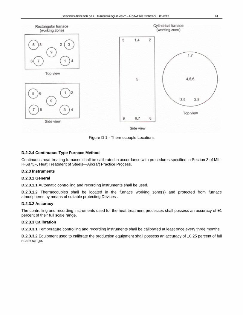
Ballot Draft
SPECIFICATION FOR DRILL THROUGH EQUIPMENT – ROTATING CONTROL DEVICES 61
Figure D 1 - Thermocouple Locations
D.2.2.4 Continuous Type Furnace Method Continuous heat-treating furnaces shall be calibrated in accordance with procedures specified in Section 3 of MIL-H-6875F, Heat Treatment of Steels—Aircraft Practice Process.
D.2.3 Instruments D.2.3.1 General D.2.3.1.1 Automatic controlling and recording instruments shall be used.
D.2.3.1.2 Thermocouples shall be located in the furnace working zone(s) and protected from furnace atmospheres by means of suitable protecting Devices .
D.2.3.2 Accuracy The controlling and recording instruments used for the heat treatment processes shall possess an accuracy of ±1 percent of their full scale range.
D.2.3.3 Calibration D.2.3.3.1 Temperature controlling and recording instruments shall be calibrated at least once every three months.
D.2.3.3.2 Equipment used to calibrate the production equipment shall possess an accuracy of ±0.25 percent of full scale range.
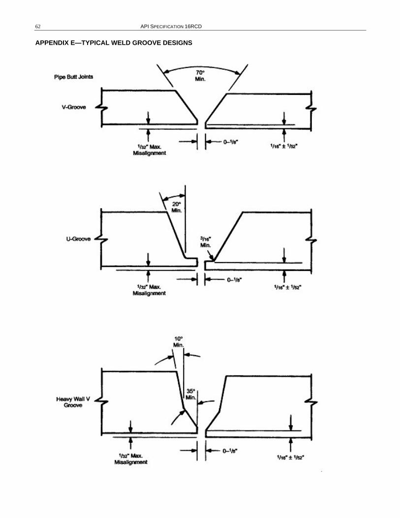
Ballot Draft
62 API SPECIFICATION 16RCD
APPENDIX E—TYPICAL WELD GROOVE DESIGNS
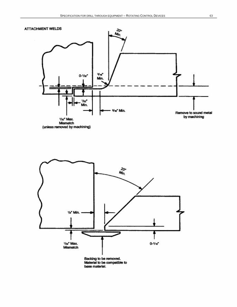
Ballot Draft
SPECIFICATION FOR DRILL THROUGH EQUIPMENT – ROTATING CONTROL DEVICES 63
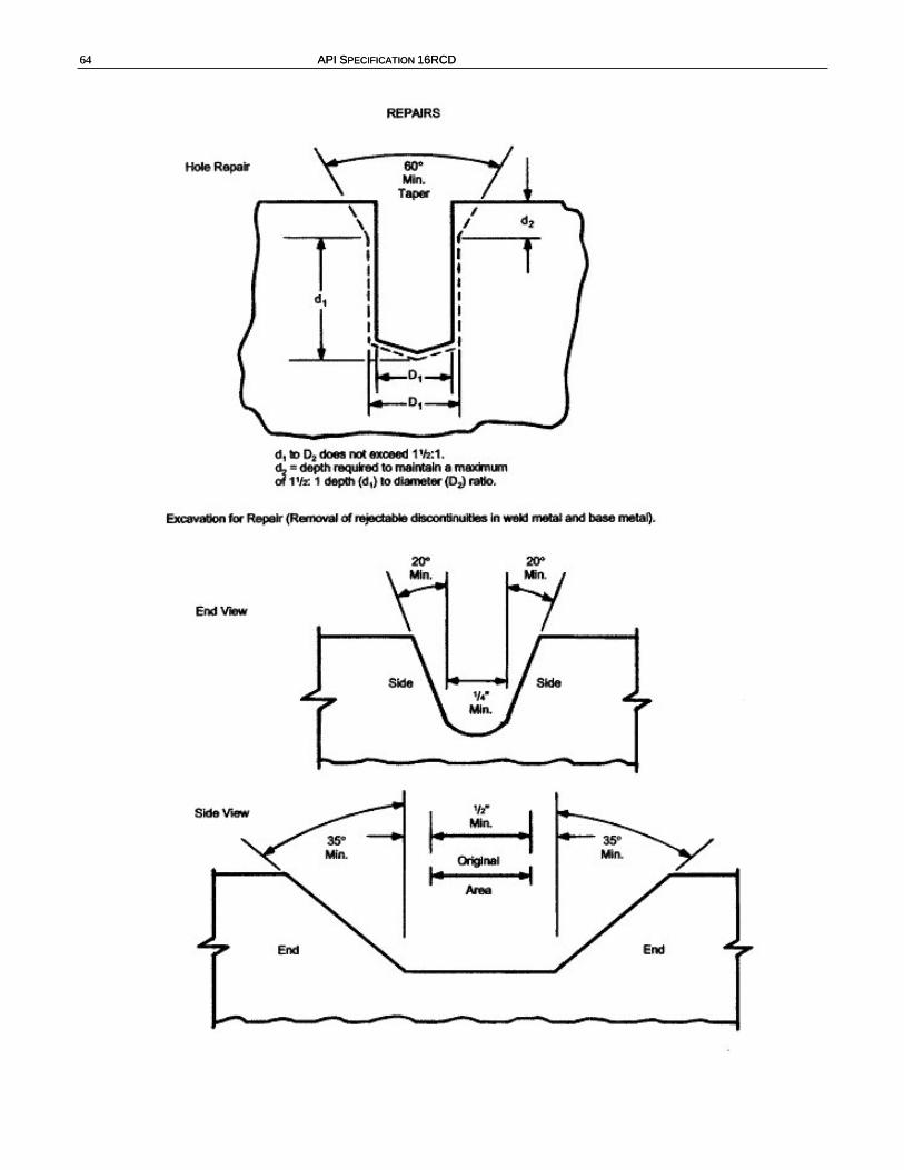
Ballot Draft
64 API SPECIFICATION 16RCD 64 API SPECIFICATION 16RCD
Ballot Draft
SPECIFICATION FOR DRILL THROUGH EQUIPMENT – ROTATING CONTROL DEVICES 65
APPENDIX F— PURCHASING GUIDELINES FOR ROTATING CONTROL DEVICES Note: This appendix provides recommended guidelines for inquiry and purchase of API Spec 16RCD equipment.
F.1 Size Designation The size designation consists of the vertical bore through the body, the bore through the bearing and the size of top, outlet and bottom flanges.
F.2 Service Conditions F.2.1 Rated static pressure The rated static pressure is determined by the lowest pressure rating of all integral end or outlet connections. Rated static pressures for API Spec 16RCD equipment are given in 4.2.1.
F.2.2 Temperature Rating Minimum temperature is the lowest ambient temperature to which the equipment may be subjected. Maximum temperature is the highest temperature of the fluid which may flow through the equipment.
F.2.2.1 Metallic Materials Metallic parts will be designed to operate in 1 of 3 temperature ratings, which should be designated by the purchaser. These ratings can be found in Table 1.
F.2.2.2 Wellbore Elastomeric Materials The purchaser should provide the temperature range for which wellbore elastomeric materials must operate. These ratings can be found in 8.3.4.3.
F.2.2.3 All Other Elastomeric Seals The purchaser should provide the temperature range for which all other elastomeric materials must operate.
F.3 Outlet Connections The purchaser should determine the number, location, size, pressure, and temperature ratings for all outlet connections. It should be noted that the pressure rating for the RCD or drilling spool is determined by the lowest pressure rating of all end or outlet connections.
F.4 Equipment Details/Data Book Supply of a data book shall require a request by the purchaser and shall contain the following information:
a. Purchase order number/sales order number.
b. Product identification, type, part number, serial number.
c. Date of completion and inspection.
d. Assembly drawings, actual overall package dimensions, pressure rating, end connection/outlet description, weight, center of gravity, material where used list.
e. Manufacturer’s statement of compliance to current edition of API Spec 16RCD.
f. Material certificates.
g. Welding procedure qualification.
h. NDE reports.
i. Pressure test reports.
Ballot Draft
66 API SPECIFICATION 16RCD
APPENDIX G—FAILURE REPORTING G.1 User Recommendation The operator of RCDs manufactured to this specification shall provide a written report to the equipment manufacturer of any malfunction or failure which occurs. This report shall include as much information as possible as to the operating conditions that existed at the time of the malfunction or failure, and any operating history of the RCDs leading up to the malfunction or failure (e.g., field repair, modifications made to the RCDs, etc.).
G.2 Manufacturer’s Recommendation G.2.1 Manufacturer’s Internal Requirements All significant problems experienced with RCDs furnished to this specification noted during its manufacture, testing or use shall be formally communicated to the individual or group within the manufacturer’s organization responsible for the design and specification documents.
The manufacturer shall have a written procedure that describes forms and procedures for making this type of communication, and the manufacturer shall provide written records of progressive design, material changes or other corrective actions taken for each model and size of RCDs.
G.2.2 Manufacturer’s External Recommendations All significant problems experienced with RCDs furnished to this specification should be reported in writing to each and every operator of the RCDs within six weeks after the occurrence. Design changes resulting from a malfunction or failure history of RCDs manufactured to this specification shall be communicated within thirty days after the design change by the manufacturer to each and every operator using the model or size RCDs having the malfunctions or failures, and all models of other RCDs that could have similar potential problems.
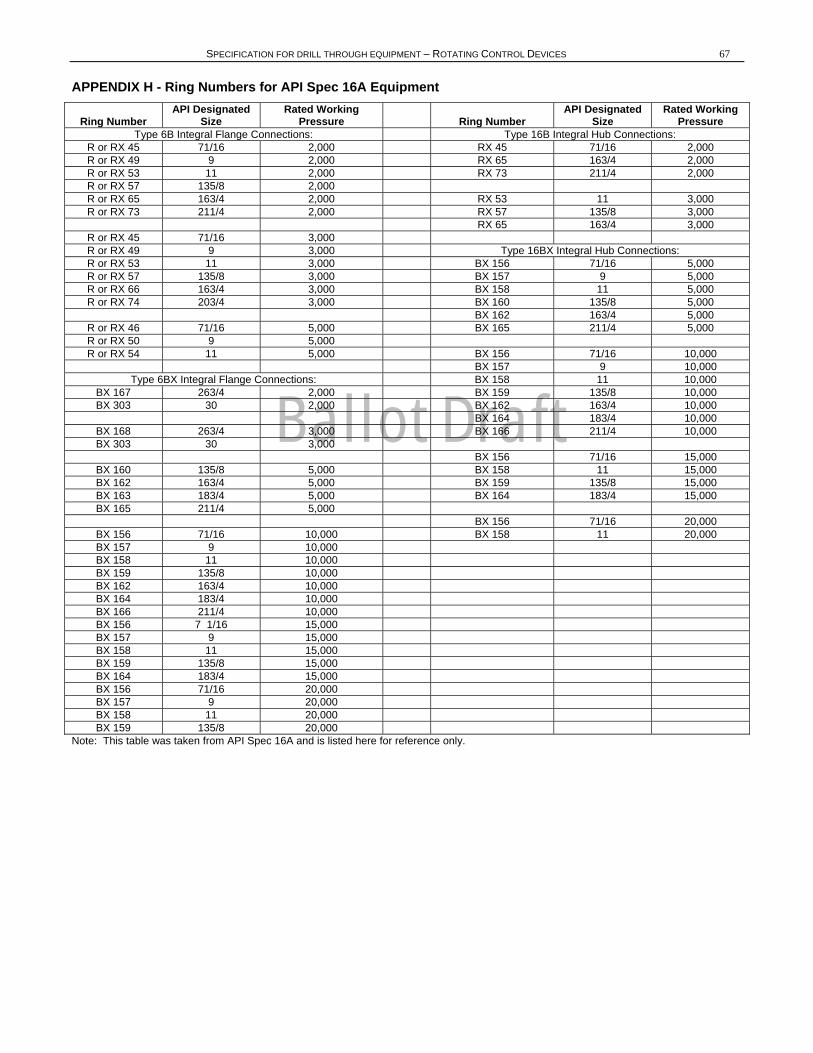
Ballot Draft
SPECIFICATION FOR DRILL THROUGH EQUIPMENT – ROTATING CONTROL DEVICES 67
APPENDIX H - Ring Numbers for API Spec 16A Equipment
Ring Number API Designated
Size Rated Working
Pressure Ring Number API Designated
Size Rated Working
Pressure Type 6B Integral Flange Connections: Type 16B Integral Hub Connections:
R or RX 45 71/16 2,000 RX 45 71/16 2,000 R or RX 49 9 2,000 RX 65 163/4 2,000 R or RX 53 11 2,000 RX 73 211/4 2,000 R or RX 57 135/8 2,000 R or RX 65 163/4 2,000 RX 53 11 3,000 R or RX 73 211/4 2,000 RX 57 135/8 3,000
RX 65 163/4 3,000 R or RX 45 71/16 3,000 R or RX 49 9 3,000 Type 16BX Integral Hub Connections: R or RX 53 11 3,000 BX 156 71/16 5,000 R or RX 57 135/8 3,000 BX 157 9 5,000 R or RX 66 163/4 3,000 BX 158 11 5,000 R or RX 74 203/4 3,000 BX 160 135/8 5,000
BX 162 163/4 5,000 R or RX 46 71/16 5,000 BX 165 211/4 5,000 R or RX 50 9 5,000 R or RX 54 11 5,000 BX 156 71/16 10,000
BX 157 9 10,000 Type 6BX Integral Flange Connections: BX 158 11 10,000
BX 167 263/4 2,000 BX 159 135/8 10,000 BX 303 30 2,000 BX 162 163/4 10,000
BX 164 183/4 10,000 BX 168 263/4 3,000 BX 166 211/4 10,000 BX 303 30 3,000
BX 156 71/16 15,000 BX 160 135/8 5,000 BX 158 11 15,000 BX 162 163/4 5,000 BX 159 135/8 15,000 BX 163 183/4 5,000 BX 164 183/4 15,000 BX 165 211/4 5,000
BX 156 71/16 20,000 BX 156 71/16 10,000 BX 158 11 20,000 BX 157 9 10,000 BX 158 11 10,000 BX 159 135/8 10,000 BX 162 163/4 10,000 BX 164 183/4 10,000 BX 166 211/4 10,000 BX 156 7 1/16 15,000 BX 157 9 15,000 BX 158 11 15,000 BX 159 135/8 15,000 BX 164 183/4 15,000 BX 156 71/16 20,000 BX 157 9 20,000 BX 158 11 20,000 BX 159 135/8 20,000
Note: This table was taken from API Spec 16A and is listed here for reference only.