antonio marinucci, ph.d, pe - stgec conference stgec - evaluation... · antonio marinucci, ph.d, pe...
TRANSCRIPT
Evaluation Evaluation and Guidance Development and Guidance Development ppfor Postfor Post‐‐Grouted Drilled Shafts for Grouted Drilled Shafts for
HighwaysHighwaysHighwaysHighways
Antonio Marinucci, Ph.D, PEDirector of Operations ADSCDirector of Operations, ADSC
Silas Nichols, PEPrincipal Geotechnical Engineer, FHWA
Benjamin S Rivers PEBenjamin S. Rivers, PEGeotechnical Engineer, FHWA – Resource Center

OverviewOverview
•• PostPost‐‐grouting Defined & Conceptgrouting Defined & Concept
•• Objectives of ProjectObjectives of Project
•• StateState‐‐ofof‐‐thethe‐‐Practice SummaryPractice Summary
•• Focus of Ongoing ResearchFocus of Ongoing Research
PostPost‐‐grouting Definedgrouting Defined
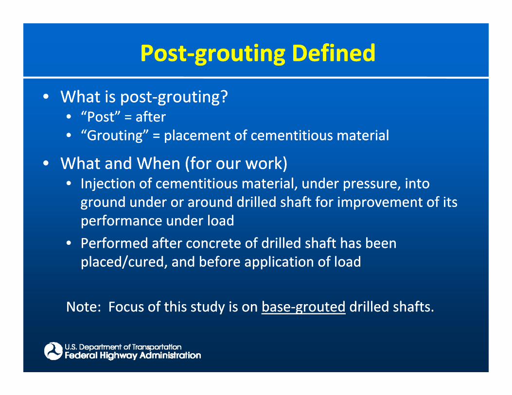
•• What is postWhat is post‐‐grouting?grouting?•• “Post” = after“Post” = after•• “Grouting” = placement of cementitious material“Grouting” = placement of cementitious material
•• What and When (for our work)What and When (for our work)•• Injection of cementitious material, under pressure, into Injection of cementitious material, under pressure, into ground under or around drilled shaft for improvement of its ground under or around drilled shaft for improvement of its performance under loadperformance under loadperformance under loadperformance under load
•• Performed after concrete of drilled shaft has been Performed after concrete of drilled shaft has been placed/cured, and before application of loadplaced/cured, and before application of load
Note: Focus of this study is on Note: Focus of this study is on basebase‐‐groutedgrouted drilled shafts.drilled shafts.

Purpose of PostPurpose of Post‐‐groutinggrouting
•• Design verificationDesign verification•• PrePre‐‐mobilize tipmobilize tip‐‐resistanceresistancePrePre mobilize tipmobilize tip resistanceresistance
•• Verifying Verifying lowerlower‐‐bound resistancebound resistance
•• Risk mitigationRisk mitigation•• Risk mitigationRisk mitigation•• Reduce uncertainties with bottom cleanlinessReduce uncertainties with bottom cleanliness
•• Cost considerationCost consideration•• Shorten Shorten shafts based on improved shafts based on improved resistanceresistance
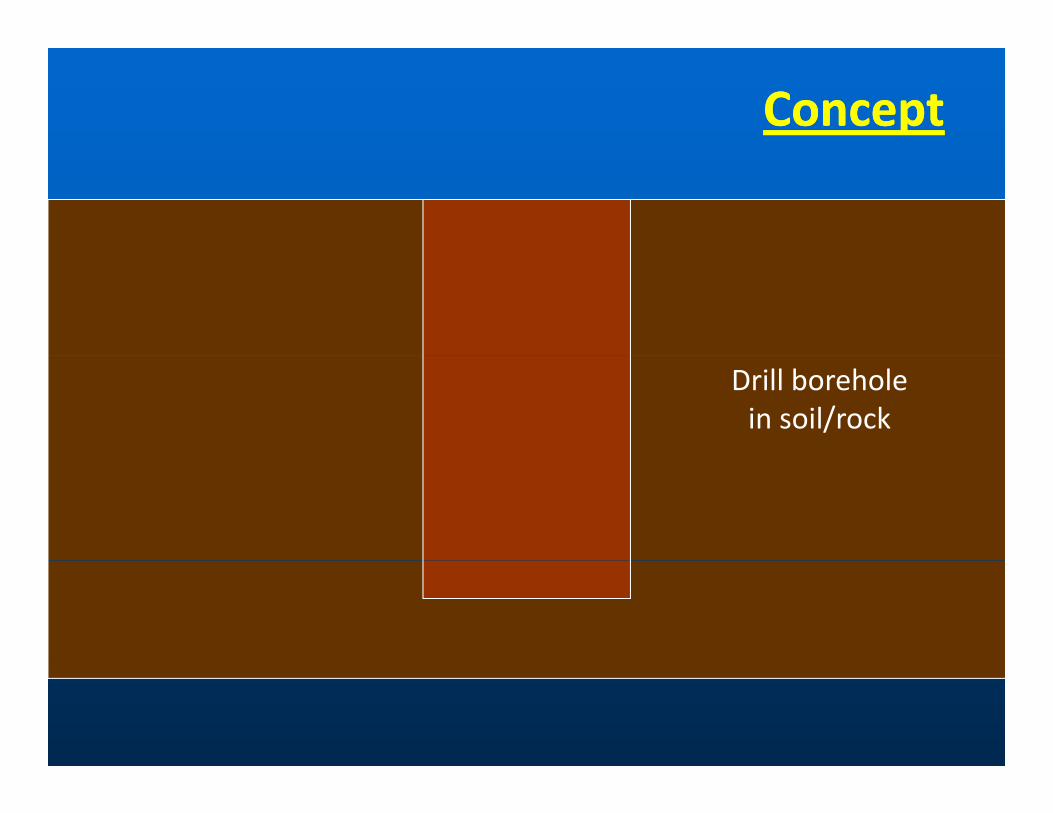
ConceptConcept
Drill borehole in soil/rock

ConceptConcept
Place reinforcement, NDT tubes, and post‐grouting devicesgrouting devices
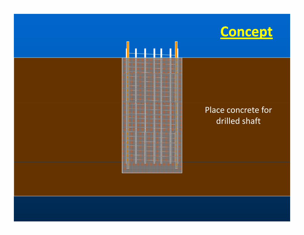
ConceptConcept
Place concrete for drilled shaft

ConceptConcept
Attach grout lines and water flush theand water flush the grout pipes w/in drilled shaft
(continue untilreturn is clear)

ConceptConcept
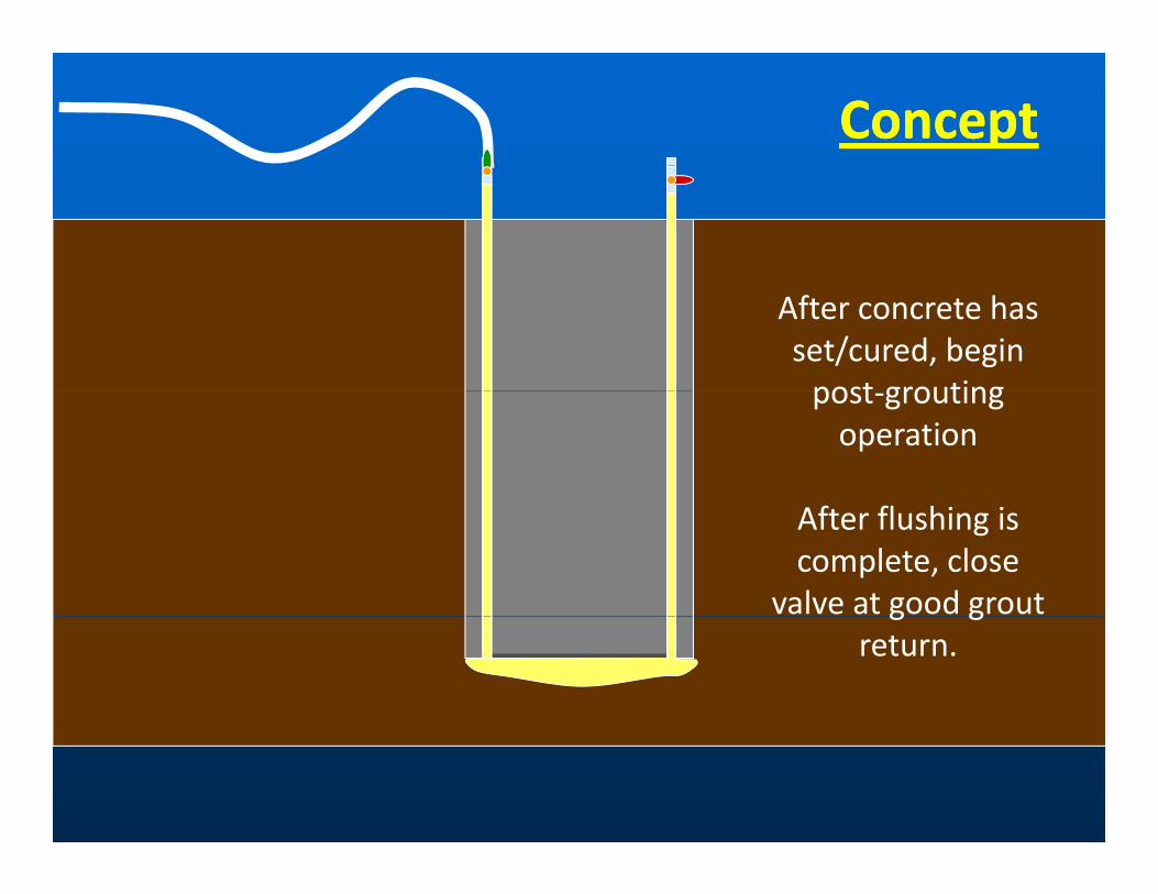
After concrete has set/cured, begin post groutingpost‐grouting operation
After flushing is complete, close
valve at good grout g greturn.
ConceptConcept
After concrete has set/cured, begin post groutingpost‐grouting operation
After flushing is complete, close
valve at good grout g greturn.

ConceptConceptGroutpressure
Upwardpdisplacement
Continue injection of grout until
criteria is achieved
Volumeof groutg

ConceptConceptUpwardp
displacement
Following post‐i bgrouting, base
resistance has been mobilized and there is a reversal of side
resistance
Volumeof grout

Objectives of StudyObjectives of Study
•• Develop Develop consensus consensus opinionopinion•• ImprovedImproved understanding of how it worksunderstanding of how it worksImproved Improved understanding of how it worksunderstanding of how it works
•• Appropriate application of postAppropriate application of post‐‐groutinggrouting
•• Guidance Guidance documents to facilitate rational and reliable design documents to facilitate rational and reliable design ggand construction of postand construction of post‐‐grouted drilled grouted drilled shaftsshafts
•• Primary objectivesPrimary objectivesPrimary objectivesPrimary objectives•• Bound use of postBound use of post‐‐grouting for current grouting for current state of state of knowledgeknowledge
•• Quantify Quantify improvement improvement mechanism(s) for mechanism(s) for postpost‐‐groutinggroutingQ yQ y pp ( )( ) pp g gg g
•• Develop design methodology(Develop design methodology(iesies) for ) for appropriate useappropriate use
•• Provide method(s) for Provide method(s) for verificationverification
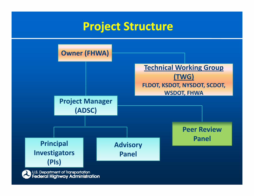
Project StructureProject Structure
Owner (FHWA)
Technical Working Group (TWG)
FLDOT KSDOT NYSDOT SCDOT
Project Manager (ADSC)
FLDOT, KSDOT, NYSDOT, SCDOT, WSDOT, FHWA
(ADSC)
Peer Review
Principal Investigators
(PI )
AdvisoryPanel
Panel
(PIs)
StateState‐‐ofof‐‐thethe‐‐PracticePractice Overview ofOverview ofPostPost‐‐groutinggrouting
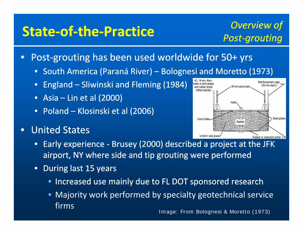
•• PostPost‐‐grouting has been used worldwide for 50+ grouting has been used worldwide for 50+ yrsyrs•• SouthSouth AmericaAmerica (Paraná(Paraná RiverRiver)) –– BolognesiBolognesi andand MorettoMoretto (1973)(1973)South South America America (Paraná (Paraná RiverRiver)) BolognesiBolognesi and and MorettoMoretto (1973)(1973)
•• England England –– SliwinskiSliwinski and Fleming (1984and Fleming (1984))
•• Asia Asia –– Lin et al (2000)Lin et al (2000)
•• Poland Poland –– KlosinskiKlosinski et et al (2006)al (2006)
•• United StatesUnited StatesUnited States United States •• Early experience Early experience ‐‐ Brusey (2000) described a project Brusey (2000) described a project at the JFK at the JFK airport, NY where side and tip grouting were performedairport, NY where side and tip grouting were performed
•• During last 15 yearsDuring last 15 years
•• Increased Increased use use mainly due to FL DOT mainly due to FL DOT sponsored sponsored researchresearch
• Majority work performed by specialty geotechnical service firms
Image: From Bolognesi & Moretto (1973)

StateState‐‐ofof‐‐thethe‐‐PracticePractice Mechanisms forMechanisms forImproving PerformanceImproving Performance
•• 4 improvement mechanisms described 4 improvement mechanisms described in the in the literatureliterature
““ l d ” fl d ” f d ll d h fd ll d h f1.1. Due Due to “preto “pre‐‐loading” of loading” of drilled shaftdrilled shaft
2.2. Due Due to improvement of the ground beneath the shaft to improvement of the ground beneath the shaft tiptip
•• Densification Densification of of ground near tip of the shaftground near tip of the shaft
•• Permeation Permeation of grout of grout into ground at tip into ground at tip of of the shaftthe shaft
3.3. Due Due to to enlarged enlarged tip areatip area
4.4. Due Due to upward flow of grout around the perimeter of the to upward flow of grout around the perimeter of the shaftshaft
StateState‐‐ofof‐‐thethe‐‐PracticePractice Mechanisms forMechanisms forImproving PerformanceImproving Performance
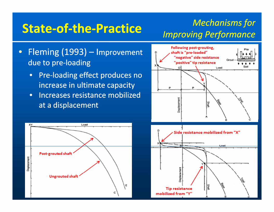
•• Fleming (Fleming (1993) 1993) –– IImprovement mprovement due due to to prepre‐‐loadingloadingpp gg
•• PrePre‐‐loading effect produces no loading effect produces no increase in ultimate increase in ultimate capacitycapacityII ii bili dbili d•• Increases Increases resistance resistance mobilized mobilized at a at a displacementdisplacement

StateState‐‐ofof‐‐thethe‐‐PracticePractice Mechanisms forMechanisms forImproving PerformanceImproving Performance
•• Ruiz (2005) Ruiz (2005) ‐‐ improvement in shaft resistance due toimprovement in shaft resistance due to
•• Compression of the soil under the pile tip (“stiffer”Compression of the soil under the pile tip (“stiffer” response)response)•• Compression of the soil under the pile tip ( stiffer Compression of the soil under the pile tip ( stiffer response)response)
•• Redistribution of residual stresses along the shaft due to the Redistribution of residual stresses along the shaft due to the upward movement of the shaft during grouting (“preupward movement of the shaft during grouting (“pre‐‐loading”)loading”)upward movement of the shaft during grouting ( preupward movement of the shaft during grouting ( pre loading )loading )
•• Increase Increase of the tip area due to the formation of a grout bulb of the tip area due to the formation of a grout bulb (increased ultimate tip resistance and stiffness(increased ultimate tip resistance and stiffness))
Compression of thesoil under the pile tip
Redistribution of stresses along shaft due to upward movement during
groutingincrease of pile tip area due to
formation of grout bulb
StateState‐‐ofof‐‐thethe‐‐PracticePractice Mechanisms forMechanisms forImproving PerformanceImproving Performance
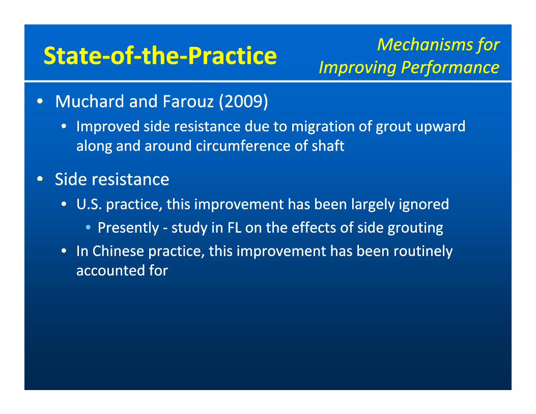
•• Muchard and Farouz (2009)Muchard and Farouz (2009)•• ImprovedImproved side resistanceside resistance due to migration ofdue to migration of groutgrout upwardupwardImproved Improved side resistance side resistance due to migration of due to migration of grout grout upward upward along and around circumference of shaftalong and around circumference of shaft
•• Side resistanceSide resistanceSide resistanceSide resistance•• U.S. practice, this improvement has U.S. practice, this improvement has been largely been largely ignoredignored
•• Presently Presently ‐‐ study in FL on the effects of side groutingstudy in FL on the effects of side groutingyy y g gy g g
•• In Chinese practice, this improvement has been routinely In Chinese practice, this improvement has been routinely accounted foraccounted for

StateState‐‐ofof‐‐thethe‐‐PracticePractice GroutingGroutingMechanismsMechanisms
•• Tip Tip grouting grouting mechanismsmechanisms•• Stem (orifice)Stem (orifice) distribution systemdistribution systemStem (orifice)Stem (orifice) distribution systemdistribution system
•• SleeveSleeve‐‐port (tubeport (tube‐‐áá‐‐manchette) distribution manchette) distribution systemsystem
•• FlatFlat‐‐jack jack distribution distribution systemsystemjj yy
•• Gravel pack w/ sleeveGravel pack w/ sleeve‐‐port or flatport or flat‐‐jack jack distribution distribution systemsystem
G bG b•• Grout tubesGrout tubes•• Typically Typically ‐‐ 11‐‐inch diameter, schedule 80 PVCinch diameter, schedule 80 PVC
•• AlsoAlso CSL tubes have been usedCSL tubes have been used 22 inch diam sched 40 steelinch diam sched 40 steel•• Also Also ‐‐ CSL tubes have been used CSL tubes have been used ‐‐ 22‐‐inch diam, sched 40 steelinch diam, sched 40 steel
•• Transition to steel pipe required for segments that extend Transition to steel pipe required for segments that extend through the top of shaftthrough the top of shaftg pg p
StateState‐‐ofof‐‐thethe‐‐PracticePractice GroutingGroutingMechanismsMechanisms
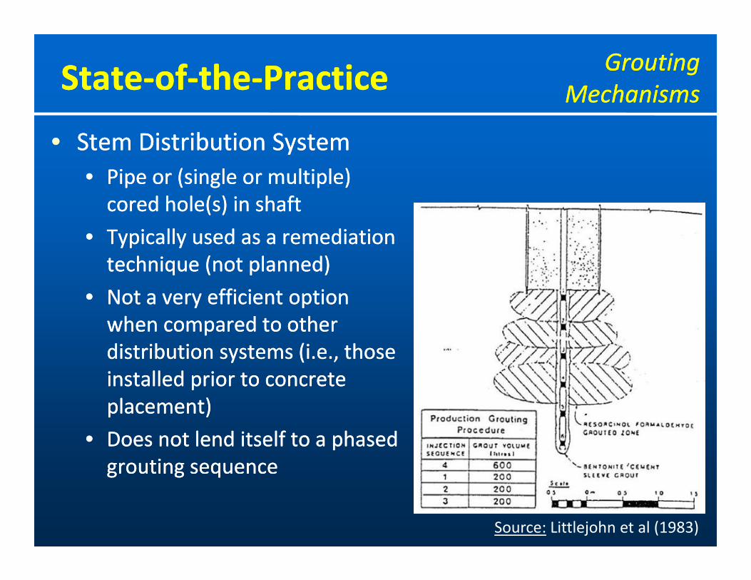
•• Stem Distribution SystemStem Distribution System•• Pipe or (single or multiple)Pipe or (single or multiple)Pipe or (single or multiple) Pipe or (single or multiple) cored hole(s) in shaftcored hole(s) in shaft
•• Typically used as a remediation Typically used as a remediation technique (not planned)technique (not planned)
•• Not a Not a very efficient option very efficient option when compared towhen compared to otherotherwhen compared to when compared to other other distribution systems (i.e., those distribution systems (i.e., those installed prior installed prior to concrete to concrete l )l )placement)placement)
•• Does not Does not lend itself to a phased lend itself to a phased groutinggrouting sequencesequencegrouting grouting sequencesequence
Source: Littlejohn et al (1983)

StateState‐‐ofof‐‐thethe‐‐PracticePractice GroutingGroutingMechanismsMechanisms
•• SleeveSleeve‐‐port port ((tubetube‐‐áá‐‐manchette) Distribution Systemmanchette) Distribution System
•• Steel plateSteel plate separationseparation•• Steel plate Steel plate –– separationseparation
•• Scuff ring Scuff ring –– for strength for strength andand to “contain”to “contain” groutgroutand and to contain to contain groutgrout
•• Gravel Pack Gravel Pack ‐‐ to level baseto level base
Source: Mullins et al (2001)Source: Mullins et al (2001)

StateState‐‐ofof‐‐thethe‐‐PracticePractice GroutingGroutingMechanismsMechanisms
•• SleeveSleeve‐‐port Distribution Systemport Distribution System•• Shafts with a flat bottomShafts with a flat bottom
Courtesy:Applied
FoundationFoundation Testing
Source: Sliwinski and Fleming (1984) Source: FHWA (2010)
StateState‐‐ofof‐‐thethe‐‐PracticePractice GroutingGroutingMechanismsMechanisms
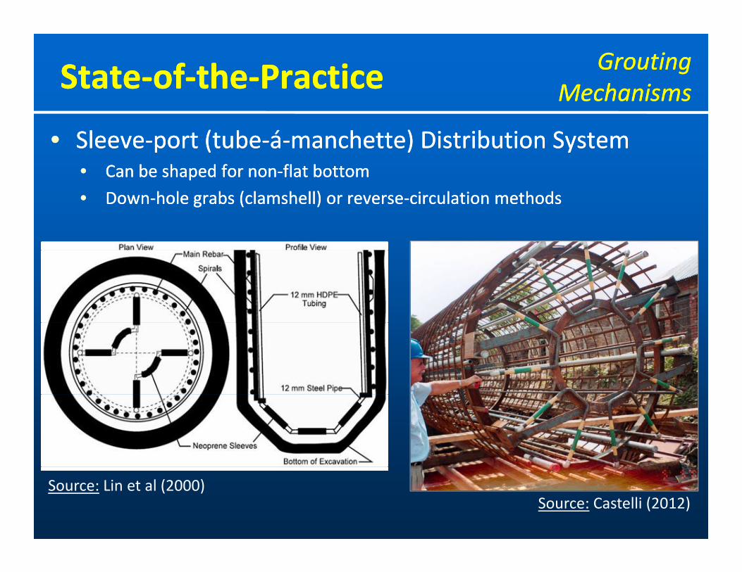
•• SleeveSleeve‐‐port port (tube(tube‐‐áá‐‐manchette) manchette) Distribution SystemDistribution System•• Can be shaped for nonCan be shaped for non‐‐flat bottomflat bottompp
•• DownDown‐‐hole grabs (clamshell) or reversehole grabs (clamshell) or reverse‐‐circulation methodscirculation methods
Source: Castelli (2012)Source: Lin et al (2000)

StateState‐‐ofof‐‐thethe‐‐PracticePractice GroutingGroutingMechanismsMechanisms
•• FlatFlat‐‐jack jack (“Pre(“Pre‐‐load cell”) Distribution Systemload cell”) Distribution System•• Grout is injected between steel Grout is injected between steel plate and rubber plate and rubber membrane (expands)membrane (expands)jj pp ( p )( p )
Source: FHWA (2010)
Source: Mullins et al (2001)

StateState‐‐ofof‐‐thethe‐‐PracticePractice GroutGroutPropertiesProperties
•• Most commonMost common•• CementCement‐‐based (simple waterbased (simple water‐‐cement mix)cement mix)CementCement based (simple waterbased (simple water cement mix)cement mix)
•• Type I/II cementType I/II cement
•• (Admixtures (Admixtures ‐‐ control flowability and set times)control flowability and set times)
•• Typical water/cement ratios Typical water/cement ratios –– 0.4 to 0.6 (high as 0.7)0.4 to 0.6 (high as 0.7)
•• Important properties of grout mixImportant properties of grout mix•• Important properties of grout mixImportant properties of grout mix•• FlowFlow, pumpability, viscosity, , pumpability, viscosity, comp. strength, colloidal naturecomp. strength, colloidal nature
•• Quality control (in field)Quality control (in field)•• Quality control (in field)Quality control (in field)•• Specific gravity measured using mud balanceSpecific gravity measured using mud balance
•• Fluidity (flowability) measured with a flow coneFluidity (flowability) measured with a flow coneFluidity (flowability) measured with a flow coneFluidity (flowability) measured with a flow cone

StateState‐‐ofof‐‐thethe‐‐PracticePractice Measurements andMeasurements andQuality ControlQuality Control
•• Quality Control during groutingQuality Control during grouting•• Grout Grout PressurePressure
•• Measured with a bourdon gaugeMeasured with a bourdon gauge•• Min. pressure is specifiedMin. pressure is specified•• Max pressure is determinedMax pressure is determined•• Max. pressure is determinedMax. pressure is determined
(ground, grouting conditions)(ground, grouting conditions)
•• Grout VolumeGrout Volume•• Min. and max. volume (cubic feet or liters) Min. and max. volume (cubic feet or liters) is is specifiedspecified
•• TopTop‐‐ofof‐‐Shaft DisplacementShaft Displacement•• Max. displacement is specified (typically ¼ to ½ inch)Max. displacement is specified (typically ¼ to ½ inch)
•• Phased Phased groutinggrouting•• Performed if desired pressure / grout volume not Performed if desired pressure / grout volume not
achieved; upward movement excessiveachieved; upward movement excessive
StateState‐‐ofof‐‐thethe‐‐PracticePractice Measurements andMeasurements andQuality ControlQuality Control
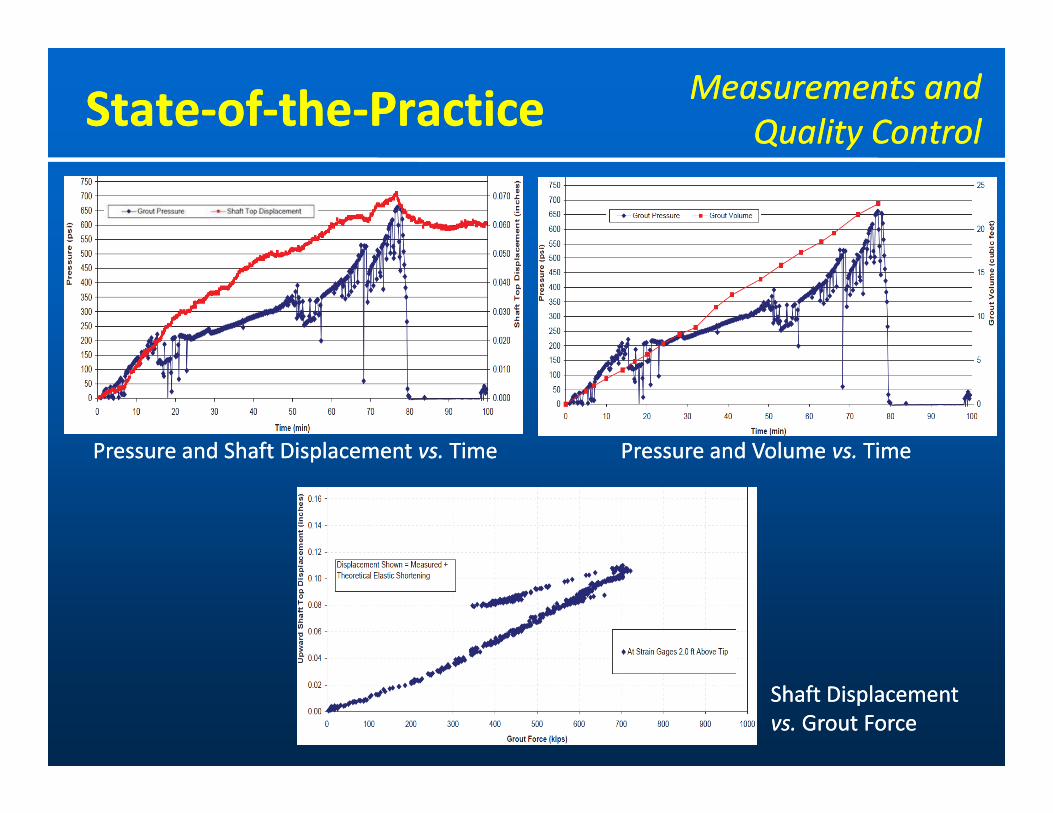
Pressure and Shaft DisplacementPressure and Shaft Displacement vs.vs. TimeTime Pressure and VolumePressure and Volume vs.vs. TimeTimePressure and Shaft Displacement Pressure and Shaft Displacement vs.vs. TimeTime Pressure and Volume Pressure and Volume vs.vs. TimeTime
Shaft Displacement Shaft Displacement vs.vs. Grout ForceGrout Force

StateState‐‐ofof‐‐thethe‐‐PracticePractice Measurements andMeasurements andQuality ControlQuality Control
•• Quality Control during grouting Quality Control during grouting ‐‐ Strain gaugesStrain gauges•• How How effectively effectively grout grout has distributed across has distributed across base of shaftbase of shaftyy gg•• Compared to grout pressure and shaft upliftCompared to grout pressure and shaft uplift
Courtesy:Courtesy: Applied Applied Foundation TestingFoundation Testing

StateState‐‐ofof‐‐thethe‐‐PracticePractice DesignDesignMethodsMethods
••

StateState‐‐ofof‐‐thethe‐‐PracticePractice DesignDesignMethodsMethods
•• Tip Capacity MultiplierTip Capacity Multiplier
Source:Source: Mullins et al (2006)Mullins et al (2006) Source:Source: Dapp and Brown (2010)Dapp and Brown (2010)
StateState‐‐ofof‐‐thethe‐‐PracticePractice DesignDesignMethodsMethods
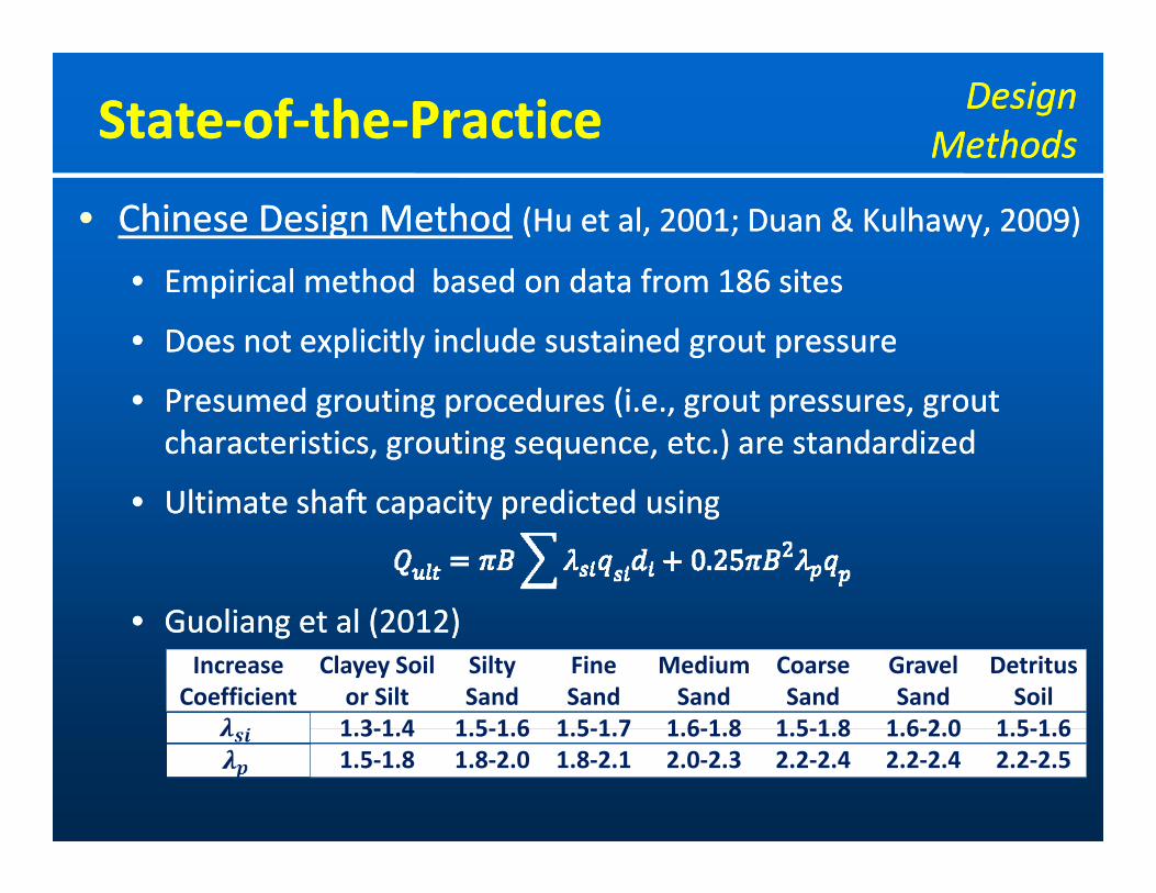
•• Chinese Design MethodChinese Design Method (Hu et al, 2001; Duan & Kulhawy, 2009)(Hu et al, 2001; Duan & Kulhawy, 2009)
•• Empirical methodEmpirical method based onbased on datadata fromfrom 186 sites186 sites•• Empirical method Empirical method based on based on data data from from 186 sites186 sites
•• Does not explicitly Does not explicitly include include sustained grout pressuresustained grout pressure
P d iP d i d (id (i•• Presumed grouting Presumed grouting procedures (i.eprocedures (i.e., ., grout pressures, grout grout pressures, grout characteristics, grouting sequence, etc.) are characteristics, grouting sequence, etc.) are standardizedstandardized
•• UltimateUltimate shaft capacityshaft capacity predicted usingpredicted using•• Ultimate Ultimate shaft capacity shaft capacity predicted usingpredicted using
•• G oliang et al (2012)G oliang et al (2012)•• Guoliang et al (2012)Guoliang et al (2012)Increase
CoefficientClayey Soil or Silt
Silty Sand
Fine Sand
Medium Sand
Coarse Sand
Gravel Sand
Detritus Soil
1 3 1 4 1 5 1 6 1 5 1 7 1 6 1 8 1 5 1 8 1 6 2 0 1 5 1 61.3‐1.4 1.5‐1.6 1.5‐1.7 1.6‐1.8 1.5‐1.8 1.6‐2.0 1.5‐1.61.5‐1.8 1.8‐2.0 1.8‐2.1 2.0‐2.3 2.2‐2.4 2.2‐2.4 2.2‐2.5

StateState‐‐ofof‐‐thethe‐‐PracticePractice DesignDesignMethodsMethods
•• Load Transfer ApproachLoad Transfer Approach (Ruiz, 2005)(Ruiz, 2005)
•• TheoreticallyTheoretically‐‐derived nonlinear curvesderived nonlinear curves (follows Fleming 1993)(follows Fleming 1993)TheoreticallyTheoretically derived nonlinear curves derived nonlinear curves (follows Fleming, 1993)(follows Fleming, 1993)
•• Load Load transfer attributed to three transfer attributed to three phenomenaphenomena•• Compression Compression of of soil soil under under shaft tipshaft tip•• Redistribution Redistribution of residual stresses of residual stresses due due to to upward movementupward movement•• Increase Increase in in shaft shaft tip area due to tip area due to formation formation of of grout bulbgrout bulb
•• tt‐‐z curve (side resistance)z curve (side resistance)tt z curve (side resistance)z curve (side resistance)
•• QQ‐‐z curve (base resistance)z curve (base resistance)
StateState‐‐ofof‐‐thethe‐‐PracticePractice DesignDesignMethodsMethods
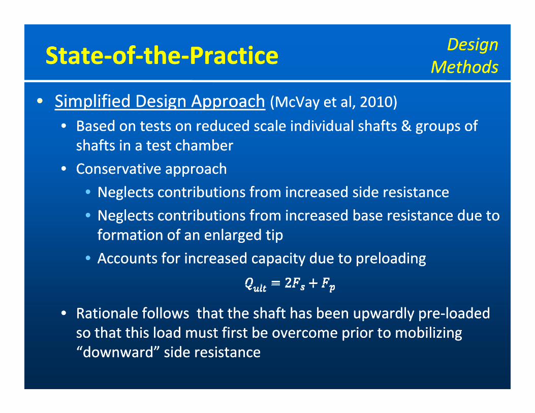
•• Simplified Design ApproachSimplified Design Approach (McVay et al, 2010)(McVay et al, 2010)
•• BasedBased onon tests ontests on reduced scale individual shaftsreduced scale individual shafts & groups& groups ofofBased Based on on tests on tests on reduced scale individual shafts reduced scale individual shafts & groups & groups of of shafts in a test shafts in a test chamberchamber
•• Conservative approachConservative approach
•• Neglects contributions Neglects contributions from increased side from increased side resistanceresistance
•• Neglects contributions from increased Neglects contributions from increased base base resistance due to resistance due to formation of an enlarged tipformation of an enlarged tipformation of an enlarged tipformation of an enlarged tip
•• Accounts Accounts for increased capacity due to for increased capacity due to preloadingpreloading
•• Rationale follows that the Rationale follows that the shaft has been upwardly preshaft has been upwardly pre‐‐loaded loaded so that this load must first be overcome prior to mobilizingso that this load must first be overcome prior to mobilizingso that this load must first be overcome prior to mobilizing so that this load must first be overcome prior to mobilizing “downward” side “downward” side resistanceresistance

StateState‐‐ofof‐‐thethe‐‐PracticePractice Preliminary FindingsPreliminary Findings‐‐ Data in SandsData in Sands

StateState‐‐ofof‐‐thethe‐‐PracticePractice Preliminary FindingsPreliminary Findings‐‐ Data in ClaysData in Clays
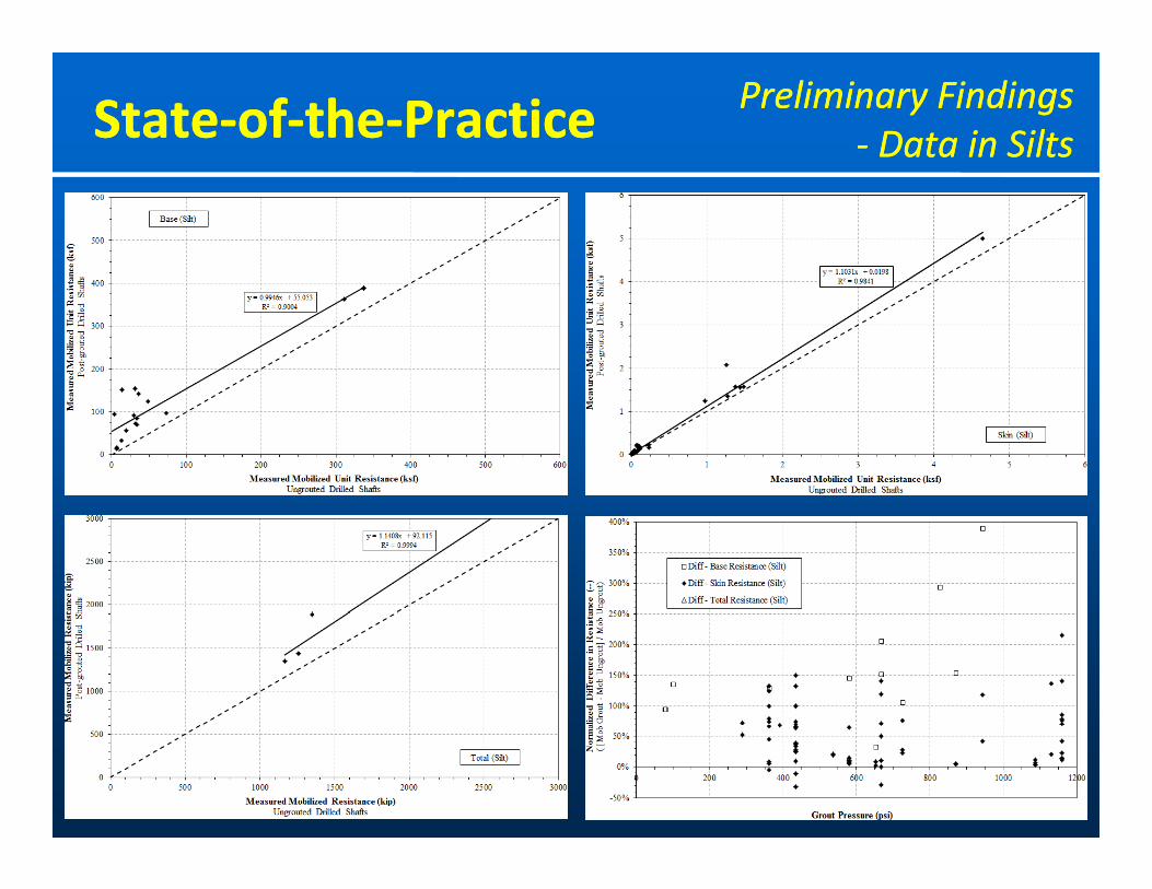
StateState‐‐ofof‐‐thethe‐‐PracticePractice Preliminary FindingsPreliminary Findings‐‐ Data in SiltsData in Silts

StateState‐‐ofof‐‐thethe‐‐PracticePractice Preliminary FindingsPreliminary Findings‐‐ Data in GravelsData in Gravels
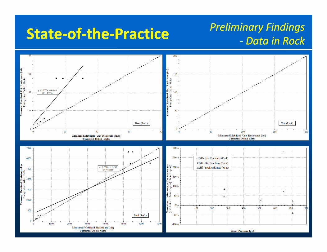
StateState‐‐ofof‐‐thethe‐‐PracticePractice Preliminary FindingsPreliminary Findings‐‐ Data in RockData in Rock
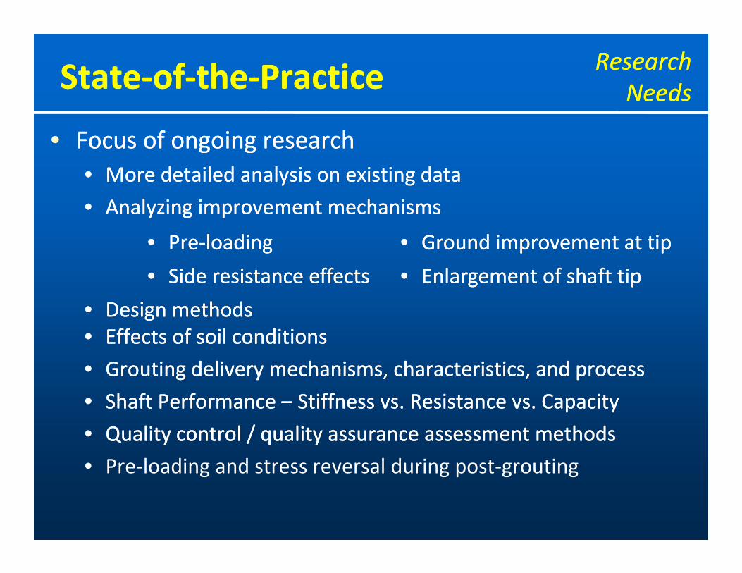
StateState‐‐ofof‐‐thethe‐‐PracticePractice ResearchResearchNeedsNeeds
•• Focus of ongoing researchFocus of ongoing research•• More detailed analysis on existing dataMore detailed analysis on existing dataMore detailed analysis on existing dataMore detailed analysis on existing data
•• Analyzing improvement mechanisms Analyzing improvement mechanisms
•• PrePre‐‐loadingloading •• Ground improvement at tipGround improvement at tip
•• Design methodsDesign methods
gg p pp p
•• Side resistance effectsSide resistance effects •• Enlargement of shaft tipEnlargement of shaft tip
•• Effects of soil conditionsEffects of soil conditions
•• Grouting delivery mechanisms, characteristics, and processGrouting delivery mechanisms, characteristics, and process
Sh fSh f P fP f S iff R i C iS iff R i C i•• Shaft Shaft Performance Performance –– Stiffness vs. Resistance vs. CapacityStiffness vs. Resistance vs. Capacity
•• Quality control / quality assurance assessment methodsQuality control / quality assurance assessment methods
• Pre‐loading and stress reversal during post‐grouting• Pre‐loading and stress reversal during post‐grouting

Th k f tt ti !!Th k f tt ti !!Thank you for your attention!!Thank you for your attention!!
Q ti ??Q ti ??Questions??Questions??