annex-2 map specifications of digital topographic...
TRANSCRIPT

ANNEX-2 Map Specifications of Digital Topographic Mapping

ANNEX-2
The Study for the Establishment of
Digital Topographic Maps and Hazard Maps
For
The Republic of Nicaragua
SPECIFICATIONS OF DIGITAL TOPOGRAPHIC
MAPPING
March, 2004
Pasco Corporation
OYO International Corporation
ANNEX-2
Table of Contents
CHAPTER 1 GENERAL................................................................................................................. 1
CHAPTER 2 CONTROL POINT SURVEY................................................................................. 2
CHAPTER 3 AERIAL PHOTOGRAPHY.................................................................................... 4
CHAPTER 4 INTERPRETATION OF AERIAL PHOTOGRAPHS AND FIELD
IDENTIFICATION............................................................................................................................ 8
CHAPTER 5 AERIAL TRIANGULATION ................................................................................ 10
CHAPTER 6 DIGITAL PLOTTING .......................................................................................... 12
CHAPTER 7 DIGITAL MAP COMPILATION ........................................................................ 14
CHAPTER 8 FIELD COMPLETION ......................................................................................... 14
CHAPTER 9 PLATE MAKING AND PRINTING.................................................................... 15
CHAPTER10 DIGITAL TOPOGRAPHIC DATA...................................................................... 16
1
SPECIFICATIONS FOR DIGITAL TOPOGRAPHIC MAPPING Chapter 1 General 1.1 Purpose The purpose of this specification is to define the method of the topographic and hazard mapping which the Japan International Co-operation Agency (JICA) conducts in the Republic of Nicaragua. 1.2 Relation with Other Specifications Surveying methods shall be in accordance with this specification except in the case of special specifications. When any other specifications are approved as equal or superior to it and permission to use these specifications are obtained in advance from JICA, they can be used. 1.3 Definition of Topographic Map In this specification, the term “topographic map” is used for base map and the hazard map at a scale of 1:50,000. 1.4 Standard Standards of surveying such as spheroid elements, etc., are; Reference spheroid: WGS84
Origin of longitude and latitude: 2952-III-I-ANA Original bench mark: NIC 0 (Boaco) Geoid model: EGM 96 1.5 Units Units of measurement shall be metric. Units of angle measurement shall be the degree, minute and second of arc. 1.6 Map Symbols Map symbols and their application rules shall be prepared by mutual consent based upon the existing specifications prepared by the Nicaraguan Institute of Territory Studies (INETER) .
2
1.7 Map Projection The projection shall be Universal Transverse Mercator Projection (UTM). 1.8 Sheet Dimension Sheet dimension is required to be based upon the specifications prepared by INETER. The size of neat lines shall be 10’ x 15’ with longitude and latitude. 1.9 Contour Interval Contour interval shall be 20m. The supplementary contours can be used every 10m in a flat area. The contour intervals for hazard map areas shall be more detailed as required of each purpose. 1.10 Precision of Map The precision of Map (in standard deviation) shall be as follows.
Table -1 Planimetry Altitude Contour line
0.51mm on the map 1/3 of contour interval 1/2 of contour interval
Chapter 2 Control Point Survey 2.1 Definition of Control Point Survey The control point survey is done to establish the necessary control points to perform aerial triangulation and mapping. 2.2 Selection of Points The position of a new GPS point shall be selected at the site where the point can be recognized easily on the aerial photograph. The point shall be chosen suitable to a ground object such as a corner or an intersection of road where the width of each road is 1m or more, a flat structure, etc., or in an open place where any obstacle does not exist in signal reception from GPS satellite. Also, temporary benchmark shall be marked within the survey pin or picket on to the decided position and a detailed point description shall be prepared. In addition, the
3
coordinates of the point shall be recorded by using a handy GPS receiver and ground photographs shall be taken for preparation of the point description.
2.3 Aerial Signal A white-painted aerial signal that is composed of three rectangles (approx. 3m×1m each), made of stones, wood plate or suitable material, in three directions centering the temporary benchmark shall be set up if the selected point is not suitable for recognition on the photo before commencement of aerial photography.
2.4 GPS Observation The GPS observation shall be executed by the static surveying method; using, geodetic GPS receivers to form the small network which unites existing reference points with the newly established points. To execute observation, the care shall be taken for the followings; (1) Expected accuracy of 3 dimensional closure errors by GPS observation shall be less than
10 PPM in compared with a trigonometric side length. (2) Measurement shall be performed with 2-hour continuous data, receiving simultaneously
at more than four (4) stations. (3) A distance to an adjacent point shall be within 30km and be close to the existing points. Furthermore, final heights of these GPS points shall be united to the leveling height obtained by leveling. 2.5 Pricking of GPS point and level point To secure accuracy for aerial triangulation, photo pricking shall be executed for the observed GPS points, existing GPS level points after execution of the aerial photography. An observed GPS point that has no aerial signal or no identifiable aerial signal on the newly taken aerial photographs shall be pricked to the Ortho-photo at a scale in the field. Direct pricking of the main point shall be executed in principle, and supplementary pricking shall be done in neighborhood of the main point where clear image is recognized on the photo. When the eccentric point element is measured for a supplementary point, "Sun azimuth measurement" or "compass azimuth measurement" shall be adopted for the short eccentric distance to the main point, and the GPS method shall be adopted for the long eccentric distance.
4
Moreover, the photo pricking of the existing level point shall be executed eccentrically to the place where the identification is easy by the aerial-photograph such as intersections on the road.
Chapter 3 Aerial Photography 3.1 Aircraft Aerial photographing aircraft shall meet the following requirements: (1) Be stable with full load while in flight to required height. (2) To have unobstructed vision in all directions. (3) To be able to install apparatus at a position where exhaust fumes will not affect the aerial
photography. (4) To have a navigation system suitable for local conditions. (5) To have an undistorted and calibrated viewfinder window glass if necessary. 3.2 Camera Aerial camera shall be a wide angle camera of format 23cm×23cm unless otherwise is specified and have the following properties: (1) minimum resolution power: 30 lines/mm (2) maximum tangential distortion: 0.05mm (3) maximum radial distortion: 0.01mm (4) flatness of film: less than 0.01mm (5) rotating inter-lens shutter (6) calibration report within 3 years with the following items:
a) camera number and lens number b) position of principal point relative to fiducial marks (in 0.01mm) c) calibrated focal length (in 0.01mm) d) radial distortion e) observer’s name and number of report
5
3.3 Navigation System GPS Navigation System for Airborne Differential GPS survey shall be installed. All photo center coordinates shall be measured by the ADGPS. 3.4 Film Aerial negative film shall have following performance capabilities. (1) After processing, ratio of differential change in dimension between longitudinal and
lateral shall not exceed 0.01%. (2) Ratio of differential change shall be also less than 0.001% per 1% of relative humidity. (3) The spectral sensitivity is panchromatic for 1:40,000 scale and color for 1:20,000 scale
unless otherwise specified. 3.5 Flight Plan Flight plan shall be made in consideration to the following items. (1) The flight lines shall be straight and drawn in relation to the aero triangulation and
mapping. (2) The average overlap is 60% and side lap 30%. 3.6 Project Area A projected area shall be photographed as a rule by an identical metric camera. 3.7 Roll of Film One meter of both sides of an aerial roll of film shall be left unexposed. A roll of film shall not be spliced as a rule for reassembly. 3.8 Data Record Name of area and date of photography shall be recorded legibly on the data recording area of film. 3.9 Flight The flight shall satisfy the following items. (1) There shall be adequate stereoscopic coverage in the photo-taking area.
6
(2) Overlap, side lap, crab, tip and tilt shall be within the following tolerances: Overlap: more than 55% and less than 65% Side lap: more than 10% Crab: less than 10 degrees Tip and tilt: less than 3 degrees
(3) The tone of photograph shall allow for details in the shade to be interpreted. (4) When a flight line is broken, that part shall be covered by an overlap of more than 2
models. (5) Photo images shall not be spoiled by cloud or mist. However, this may be permissible to
the extent of 10% if they are covered by the photographs of adjacent strips. (6) Navigation system shall for airborne differential GPS survey. All photo-center
coordinates shall be measured by the ADGPS. 3.10 Flight Record The following information shall be written on the flight record. (1) name of contract (2) name of photographing organization (3) film number (4) beginning and end times of flight (5) date of flight (6) camera number, lens number and magazine number (7) calibrated focal length (8) opening aperture, filter number and exposure time (9) type of film (10) type of aircraft (11) flight altitude 3.11 Negative Film Processing of negative film shall be carried out as follows: (1) Developer specified by manufacturer’s guidance, or one equal or superior, shall be used. (2) Development shall be carried out in such a manner that the negative contains all highlight
and shadow details and camera recording data is legible. (3) Fixer shall be acidity and fixing shall be carried out well enough to remove unused silver
7
halide. (4) Washing shall be carried out to remove undesirable residues. (5) In drying, distortions shall be avoided. (6) Photo-images shall not be marred by scratches, fingerprints smudges, pink marks or
shrinkage in the photo-processing. 3.12 Contact Print and Enlarged Photograph The preceding article is applied to the processing of paper prints. 3.13 Re-flight Film shall be developed and contact prints shall be printed for inspection as soon as possible. When the film is rejected, a re-flight shall be carried out immediately. 3.14 Editing of Negative Film The negative film shall be edited as follows, except if specified instructions are given. (1) A leader and trailer of clear film 1meter long shall be provided with all film rolls. (2) Information to be recorded on negative film includes name of area, date of flight, mission
number, strip number, photo number, flight height and name of photographing organization.
All information shall be recorded on photographs of both sides of each strip. But on the other photographs only strip number and photo number will be recorded. 3.15 Index Map Index map shall be made by using a map of appropriate scale. If no maps are usable, a photo-index shall be prepared. 3.16 Negative Film and Contact Print Negative film shall be kept into a tin labeled “flight information xx/xx/200x” in each roll. Contact prints shall be kept in sacks in each strip.
3.17 Scanning of Aerial Photographs Negative films of aerial photographs are scanned using a roller scanner at a precision level of 20 micrometers. One image of scanned photograph has 125 Mb of data. Therefore, DVD (5
8
giga-byte) will be used as medium of storage. 3.18 Simplified Aerial Triangulation
In order to make early conduct of field identification possible, a simplified-aerial triangulation shall be conducted using principal photo coordinates measured by DGPS before getting the result of the aerial triangulation.
3.19 Preparation of Simplified Photo Maps (Simplified Ortho- photos 1:25,000)
DEM with a grid interval of about 500 m is produced using the automatic procedure of a digital plotting system. Ortho-photo mosaic is produced for each sheet. The UTM coordinate values and grid are printed at the same time.
3.20 Output of Simplified Photo Maps (Simplified Ortho-photo 1:25,000)
The simplified photo maps are printed onto photographic paper at a scale of 1:25, 000 for each quadrangle of 1:50,000 topographic maps.
Chapter 4 Interpretation of Aerial Photographs and Field Identification 4.1 Use of Photo Maps Photo-interpretation for field identification is carried out using contact prints. Photo Maps produced in the former process aid the field identification work on-site to locations where interpreters have difficulties interpreting geographic features. The counterpart provides major staff for the work. The expert carefully instructs and guides staff to conduct the field identification. 4.2 Photo-interpretation for field identification Photo-interpreters interpret major geographic features on contact prints using portable stereoscopes before the field identification, referring to existing topographic maps. The target features are roads, villages, rivers, waterways, railroads and vegetation. Schools, churches and cemeteries are other features to be identified as much as possible.
9
4.3 Photograph field identification The field identification shall be classified according to PS/3AAA/101 specifications from NGA: buildings, vegetation, and other features for annotation using simple-photo maps and a handy GPS in accordance with the map symbol specifications. A handy GPS stores positional data. The data are then transferred to PCs and are used to inspecting possible error of identified results. The accuracy of the position of handy GPS is less than 15 m, and it satisfies accuracy of field identification for 1:50,000 topographic mapping. 4.4 Advanced Study Advanced studies shall be carried out as follows with aerial photographs and reference data assembled beforehand. (1) Photo Map shall be used for editing the data assembled by filed identification. (2) Studies shall be carried out on the following subject.
a) The map symbols prepared by PS/3AAA/101Spec. from NGA agreed on both side. b) Quality of the reference data and possibility of its use. c) No interpretable objects on the photographs. d) Discrepancies between reference data.
4.5 Execution Prior to execution of field identification, a deliberation has to be held with staff members from INETER concerned to the map symbols and application rules. The same may apply to the case that doubtful points have been raised on surveying. Field identification shall be carried out according to the map symbol application rule. 4.6 Editing The data gathered by the field identification shall be edited as follows on the Photo Maps. (1) The data shall be edited according to the map symbol PS/3AAA/101 specifications with
waterproof ink. (2) Positioning shall be assured using a handy GPS. (3) The geographic features shall be laid down precisely on the points.
10
(4) In case that density of detail does not permit type being placed precisely on the point, the point indicated by a spot and a leader arrow is required from the type to the spot. An overlay may be used to lay down on Photo Map when density of details is high.
Chapter 5 Aerial Triangulation 5.1 Aerial Triangulation Analytical block adjustment method is required for aerial triangulation. 5.2 Distribution of Control Points Horizontal and vertical control points shall be placed on every corner of the block. Others are distributed to the appropriate location for airborne DGPS aerial triangulation as to keep the required accuracy of the results.
5.3 Pass point and Tie Point Pass point and tie point are determined as follows. (1) Pass Points
a) Pass pint is fixed near the center of photograph and wing points on the line drawn through or near the center of photograph and perpendicular to the base line, except on water part.
b) Wing points are placed at a distance of 7 – 10 cm from pass point. c) Pass point and wing points are fixed on as flat an area as possible.
(2) Tie Points
a) More than one tie point shall be selected in a model. b) They shall be identifiable on the photographs of both strips.
(3) Marking of Points Pass points, wing points and tie point are enclosed with small red circle on the contact print.
5.4 Measurement of Photo Coordinates Measurements of coordinates of control points pass points, tie points and fiducial marks shall
11
be carried out twice by precise mono- or stereo-comparator. When the difference is less than 0.02mm the mean is adopted. 5.5 Inner Orientation (1) Effect of shrinkage of diapositive shall be considered for each photograph. (2) Distortion of aerial camera is required to be corrected. (3) Measurement error of distance between fiducial marks shall be less than 0.03mm. 5.6 Relative Orientation (1) All points of a model shall be used for relative orientation. (2) Effect of atmospheric refraction shall be considered. (3) Residual error of relative orientation shall be less than 0.03mm on the diapositive. (4) Discrepancies of model coordinates at a common point between successive models shall
be less than 0.05% of flight height for planimetry and height. 5.7 Conversion from Model Coordinates to Geodetic Coordinates (1) Independent model method is required for block adjustment. (2) Effect of earth curvature shall be corrected. (3) Discrepancies of coordinates at a common point between adjacent models shall be less
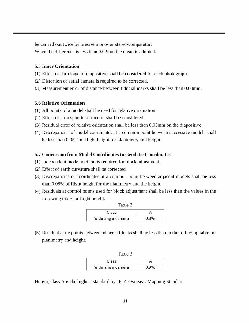
than 0.08% of flight height for the planimetry and the height. (4) Residuals at control points used for block adjustment shall be less than the values in the
following table for flight height. Table 2
Class A
Wide angle camera 0.8‰
(5) Residual at tie points between adjacent blocks shall be less than in the following table for
planimetry and height.
Table 3 Class A
Wide angle camera 0.9‰
Herein, class A is the highest standard by JICA Overseas Mapping Standard.
12
Chapter 6 Digital Plotting 6.1 Digital Plotting A detailed plotting work follows the specifications “Especificaciones para la Adquisición de Datos Topográficos Digitales” this work is based on the results of aerial triangulation, aerial-photo interpretation, and field identification. A digital plotter is the device to depict planimetric features and contour lines by providing stereoscopic vision. A relative orientation uses six points. Detailed plotting is conducted in the order of line-shaped features, buildings, and vegetation in principle. The interval of the contour is set at 20 m and the additionals at 10m. Spot heights are selected at major mountain peeks, major diverging points of roads, entry to a mouth of a valley, confluence of rivers, and critical points of inclination. The point shall be distributed evenly for the purpose of easy interpretation of topography. In order to avoid omission, a function of superimposition is to be used when plotting ground features. The plotting process is as follows (1) Loading results of aerial triangulation (2) Loading stereo-pair images to an analytical plotter (3) Digital plotting of topographic and feature data as viewed in 3D (4) Inspection of plotting sheet (5) Storing plotted data as DM data files of digital map (6) Production of DEM from topographic data using Arc GIS (7) Structuring DM Data using digital map in Arc GIS 6.2 DEM DEM (digital elevation modeling) is produced from contour lines and spot heights. The density shall be 40 m intervals. DEM is produced using Arc GIS, and the plotted data is structured. 6.3 Orientation (1) The relative orientation is carried out by using 6 points on a model and absolute
orientation by 6 points determined by aero triangulation.

13
(2) Control points in model, if exist, are used for checking the orientation. (3) Residuals of orientation are as follows:
a) Residual parallax of relative orientation shall not be exceed 0.02mm. b) Scaling error of model orientation is less than
0.3mm on the map for class A c) Leveling error of model orientation is less than
1/4 of contour interval for class A d) Measurements of spot height shall be carried out twice and the difference between the
measurements shall be less than 0.01mm.
6.4 Plotting (1) Plotting of geographic details is restricted to inside a limit obtained by connecting pass
points. (2) Plotting shall be carried out as follows.
a) Plotting error caused by height measurement error shall not occur. b) Topographic features for which distorted surface area symbol are not prepared shall
be expressed by contour lines as much as possible. c) Height shall be checked at the top of mountain, bottom of depressions and passes etc.,
to prevent the dropping of contour lines in restitution. (3) Matching of Map Sheets
a) Continuity shall be established with adjoining sheets when it is less than 0.51mm. b) When no adjoining maps exist, geographic features shall be plotted to the extent of
1cm outside on lines.
6.5 Spot Height (1) Spot height shall be measured at the following points distributed as uniformly as possible
on the map. a) Main top of mountains b) Main fork of roads c) Mouth of a valley, junction of river, riverbed d) Main changes of slopes e) Center of local plains f) Most lowest part of depression

14
(2) Independent measurements shall be carried out twice and the mean shall be adopted. (3) Earth curvature correction shall be applied when it exceeds the following limits Class A: 1/4 of contour interval Chapter 7 Digital Map Compilation 7.1 Digital Map Compilation The digital plotting data are symbolized according to PS/3AAA/101specifications, the “revised map symbols and application rules” The graphic software used is Adobe Illustrator for its use. The process of map symbolization is as follows: (1) Loading structured data files to Arc GIS (2) Data format change to Illustrator (3) New layer preparation for grid and border line (4) Preparation of texts for annotation, legend, border information (5) Shifting and adjusting map symbols from the true positions in a way to make production
of printing positives possible (6) Test print of the edited originals and checking with the results of field identification to
make necessary correction. (7) Preparation of files from the original plotting after map symbolization for plate making
film. Chapter 8 Field Completion 8.1 Field Completion The field completion clarifies uncertainties raised during the work processes of digital plotting and map symbolization. Uncertain features or annotations recorded on edited originals are brought on-site. As in the process of photo-interpretation and field identification, a handy GPS and edited originals with coordinate values aid less experienced workers to complete the work. 8.2 Working
15
(1) Field completion is carried out as follows. a) Boundaries, place names and others are laid down on the basis of data supplied from
INETER. b) Investigation of doubtful points c) Field survey if necessary d) A survey for checking the mapping accuracy is carried out if necessary.
(2) A responsible person of INETER is required to sign agreement on every sheet completed by field completion.
Chapter 9 Plate Making and Printing 9.1 Plate Making The symbolized data are separated into four layers of YMCK. The data are then printed onto films for plate making by using a high precision plotter. The output precision is set at 2000-3000 dpi. From the film, copy negatives are produced. For each copy negative, an aluminum PS plate is made. Test printing checks for hues, matching, dimension, and lines. If the test fails, the plate making process is repeated to achieve satisfactory results. The result of the final test print is subject to approval by INETER side. 9.2 Printing Map printing shall be executed in Nicaragua. The quality of paper shall be high enough to resist damages from folding, stretching, and tearing, and to be free from stretching and shrinkage. The dimension of a sheet of printed map discussed and approved by the INETER side. 500 copies are to be produced for the 60 sheets and hazard map areas. The following note shall be annotated the lower portion of each printed map: “This map was prepared jointly by Japan International Cooperation Agency (JICA) under the Japanese Government Technical Cooperation Program and Government of the Republic of Nicaragua” Prepared by the Nicaraguan Institute of Territory Studies (INETER) with the cooperation of the Japanese Government through the Japanese International Cooperation Agency (JICA),

16
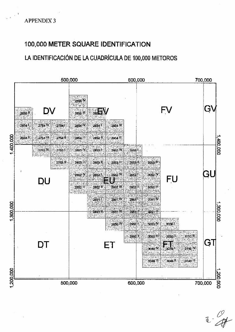
Managua, Nicaragua. Compiled in 2004 by digital photogrammetry method based on aerial photgrammetry to a scale 1: 40,000 taken in1996, 2000 and 2004. Printed in May, 2005 This map is not wholly verified in the field Chapter10 Digital Topographic Data 10.1 Vectorization Vectorization and identification of each geographic entity represented in each vector shall be conducted based on the codes discussed in the meetings and stated in Appendix 3.
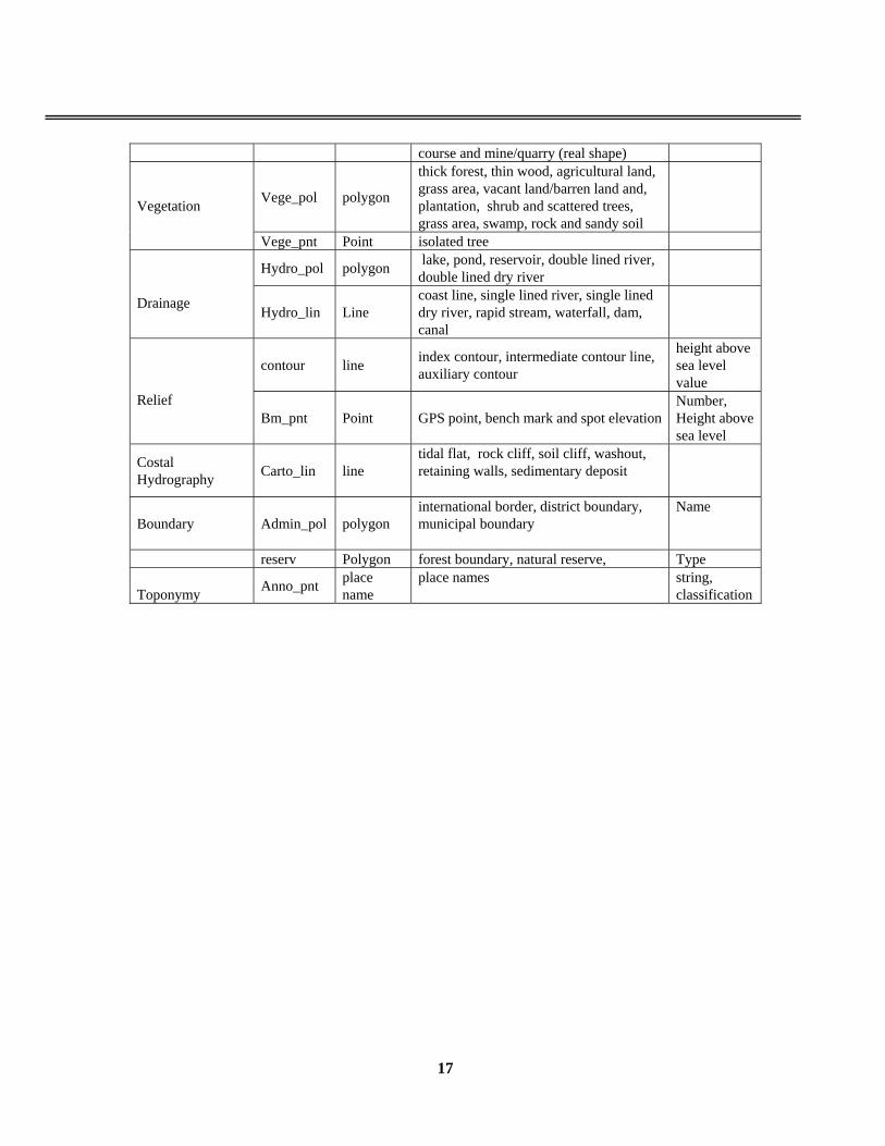
10.2 Editing and Structuring The vectorized data is structured to have topology structure so that the data can be used as a geographic information database. Data are inspected by point, line, and polygon and edited to correct physical and logical errors. The tolerance level is set to identify missing lines or recognition errors. Arc GIS is used to structure the data and the digital geographic database is produced. The specifications are as follows:
Table 4 Specifications of Topographic Mapping Database (draft) Category Layer Data Type Data Item Attribute
Road and road related facilities road line
expressway, major road, secondary road, other road, cart track, footpath, ferry, ford, bridge and tunnel
Railroad railway line single track
build_pol polygon built-up area, a public building, residence, abandoned village, monastery, church, school, hospital
Buildings
build_pnt point public building, residence, monastery, church, school, hospital,.
infra_lin line power transmission line, substation, pipeline, aqueduct, airport, airstrip
Infrastructure well Point Well etc.
Other structure landmark point monument, lighthouse, antenna, cave and water tower
Special district Built_up polygon populated area, airport, cemetery (real shape), religious facilities, stadium, golf
17
course and mine/quarry (real shape)
Vege_pol polygon
thick forest, thin wood, agricultural land, grass area, vacant land/barren land and, plantation, shrub and scattered trees, grass area, swamp, rock and sandy soil
Vegetation
Vege_pnt Point isolated tree
Hydro_pol polygon lake, pond, reservoir, double lined river, double lined dry river
Drainage Hydro_lin Line
coast line, single lined river, single lined dry river, rapid stream, waterfall, dam, canal
contour line index contour, intermediate contour line, auxiliary contour
height above sea level value
Relief Bm_pnt Point GPS point, bench mark and spot elevation
Number, Height above sea level
Costal Hydrography Carto_lin line
tidal flat, rock cliff, soil cliff, washout, retaining walls, sedimentary deposit
Boundary Admin_pol polygon international border, district boundary, municipal boundary
Name
reserv Polygon forest boundary, natural reserve, Type Toponymy Anno_pnt place
name place names
string, classification