anl anl h anl cplanetaklimata.com.ua/instr/aermec/aermec_anl_installation_maintenance... · 2...
TRANSCRIPT

IANLIY. 0906. 6755511_02 replaces 675511_01
CHILLERS AND HEAT PUMPS - Installation Maintenance Manualn MainteUMPS - Insta
ANLANL HANL C
SCROLLAXIAL
M
ODUCONTROL
ANL_INSTALLAZIONE riduzione costi_UK.indd 1 05/06/2009 10.34.45
2
AERMEC S.p.A. reserves the right at any moment to make any modifications considered necessary to improve our products and is not obliged to add these modifications to machines that have already been fabricated, delivered or are under construction.
Dear Customer,Thank you for choosing an AERMEC product. This product is the result of many ye-ars of experience and in-depth engineering research, and it is built using top quality materials and advanced technologies.Moreover, the CE mark guarantees that our appliances fully comply with the requirements of the European Machinery Directive in terms of safety. We constan-tly monitor the quality level of our products, and as a result AERMEC products are synonymous with Safety, Quality, and Reliability.
Product data may be subject to modifications deemed necessary for improving the product without the obligation to give prior notice.
Thank you again.AERMEC S.p.A
ANL_INSTALLAZIONE riduzione costi_UK.indd 2 05/06/2009 10.35.50
3
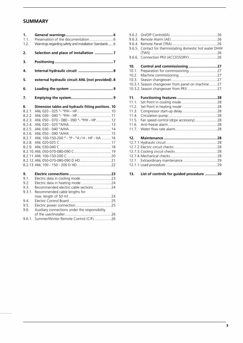
1. General warnings ..............................................61.1. Preservation of the documentation .......................61.2. Warnings regarding safety and installation Standards ......6
2. Selection and place of installation ..................7
3. Positioning .........................................................7
4. Internal hydraulic circuit ..................................8
5. external hydraulic circuit ANL (not provided) .8
6. Loading the system ..........................................9
7. Emptying the system .........................................9
8. Dimension tables and hydraulic fitting positions . 108.2.1. ANL 020 - 025 °- °P/H - HP .................................108.2.2. ANL 030 - 040 °- °P/H - HP .................................118.2.3. ANL 050 - 070 - 080 - 090 °- °P/H - HP ...............128.2.4. ANL 020 - 025 °A/HA .........................................138.2.5. ANL 030 - 040 °A/HA .........................................148.2.6. ANL 050 - 090 °A/HA .........................................158.2.7. ANL 100-150-200 ° - °P - °A / H - HP - HA ..........168.2.8. ANL 020-025 C ..................................................178.2.9. ANL 030-040 C ..................................................188.2.10. ANL 050-070-080-090 C ....................................198.2.11. ANL 100-150-200 C ...........................................208.2.12. ANL 050-070-080-090 D HD ..............................218.2.13. ANL 100 - 150 - 200 D HD .................................22
9. Electric connections .........................................239.1. Electric data in cooling mode ..............................239.2. Electric data in heating mode .............................249.3. Recommended electric cable sections .................249.3.1. Recommended cable lengths for max. length of 50 mt ..........................................249.4. Electric Control Board .........................................259.5. Electric power connection ...................................259.6. Auxiliary connections under the responsibility of the user/installer .............................................269.6.1. Summer/Winter Remote Control (C/F) .................26
9.6.2. On/Off Control(IA) ..............................................269.6.3. Remote Alarm (AE) .............................................269.6.4. Remote Panel (TRA) ............................................269.6.5. Contact for thermostating domestic hot water DHW
(TWS) ................................................................269.6.6. Connection PR3 (ACCESSORY) ...........................26
10. Control and commissioning ............................2710.1. Preparation for commissioning............................2710.2. Machine commissioning .....................................2710.3. Season changeover .............................................2710.3.1. Season changeover from panel on machine ........2710.3.2. Season changeover from PR3 .............................27
11. Functioning features .......................................2811.1. Set Point in cooling mode ...................................2811.2. Set Point in heating mode ..................................2811.3. Compressor start-up delay ..................................2811.4. Circulation pump ................................................2811.5. Fan speed control (dcpx accessory)......................2811.6. Anti-freeze alarm ................................................2811.7. Water flow rate alarm .........................................28
12. Maintenance ....................................................2812.7.1. Hydraulic circuit ..................................................2812.7.2. Electric circuit checks ..........................................2812.7.3. Cooling circuit checks .........................................2812.7.4. Mechanical checks ..............................................2812.1. Extraordinary maintenance .................................2912.1.1. Load procedure ..................................................29
13. List of controls for guided procedure ............30
SUMMARY
ANL_INSTALLAZIONE riduzione costi_UK.indd 3 05/06/2009 10.35.50
4
AERMEC S.p.A.I-37040 Bevilacqua (VR) Italy – Via Roma, 44Tel. (+39) 0442 633111Telefax 0442 93730 – (+39) 0442 93566www . aermec . com - info @ aermec . com
ANLANLH
Marketing ManagerSignature
SERIAL NUMBER
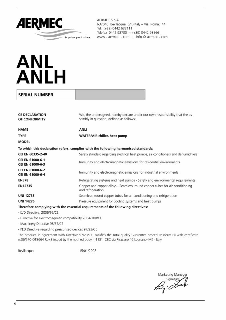
CE DECLARATION OF CONFORMITY
We, the undersigned, hereby declare under our own responsibility that the as-sembly in question, defined as follows:
NAME ANLI
TYPE WATER/AIR chiller, heat pump
MODEL
To which this declaration refers, complies with the following harmonised standards:
CEI EN 60335-2-40 Safety standard regarding electrical heat pumps, air conditioners and dehumidifiers
CEI EN 61000-6-1 CEI EN 61000-6-3
Immunity and electromagnetic emissions for residential environments
CEI EN 61000-6-2 CEI EN 61000-6-4
Immunity and electromagnetic emissions for industrial environments
EN378 Refrigerating systems and heat pumps - Safety and environmental requirements
EN12735 Copper and copper alloys - Seamless, round copper tubes for air conditioning and refrigeration
UNI 12735 Seamless, round copper tubes for air conditioning and refrigeration
UNI 14276 Pressure equipment for cooling systems and heat pumps
Therefore complying with the essential requirements of the following directives:
- LVD Directive: 2006/95/CE
- Directive for electromagnetic compatibility 2004/108/CE
- Machinery Directive 98/37/CE
- PED Directive regarding pressurised devices 97/23/CE
The product, in agreement with Directive 97/23/CE, satisfies the Total quality Guarantee procedure (form H) with certificate n.06/270-QT3664 Rev.3 issued by the notified body n.1131 CEC via Pisacane 46 Legnano (MI) - Italy
Bevilacqua 15/01/2008
ANL_INSTALLAZIONE riduzione costi_UK.indd 4 05/06/2009 10.35.51
5
AERMEC S.p.A.I-37040 Bevilacqua (VR) Italy – Via Roma, 44Tel. (+39) 0442 633111Telefax 0442 93730 – (+39) 0442 93566www . aermec . com - info @ aermec . com
SERIAL NUMBER
Marketing ManagerSignature
ANLC
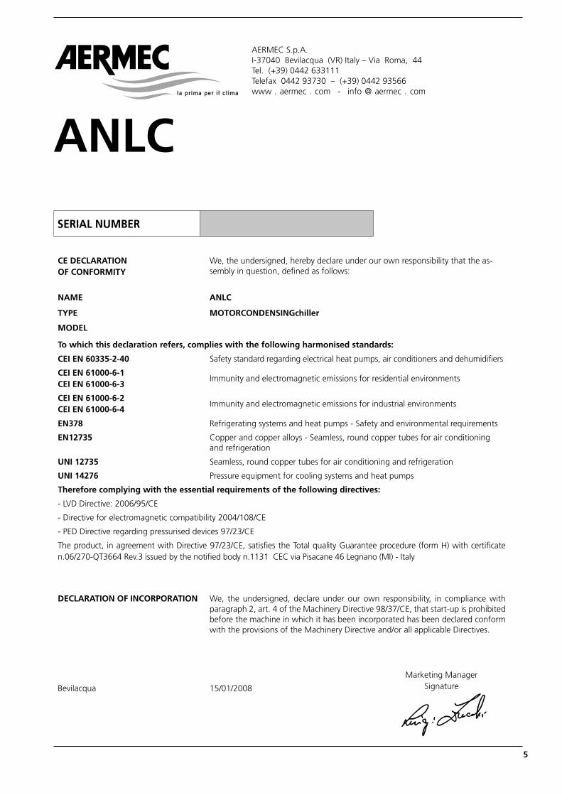
CE DECLARATION OF CONFORMITY
We, the undersigned, hereby declare under our own responsibility that the as-sembly in question, defined as follows:
NAME ANLC
TYPE MOTORCONDENSINGchiller
MODEL
To which this declaration refers, complies with the following harmonised standards:
CEI EN 60335-2-40 Safety standard regarding electrical heat pumps, air conditioners and dehumidifiers
CEI EN 61000-6-1 CEI EN 61000-6-3
Immunity and electromagnetic emissions for residential environments
CEI EN 61000-6-2 CEI EN 61000-6-4
Immunity and electromagnetic emissions for industrial environments
EN378 Refrigerating systems and heat pumps - Safety and environmental requirements
EN12735 Copper and copper alloys - Seamless, round copper tubes for air conditioning and refrigeration
UNI 12735 Seamless, round copper tubes for air conditioning and refrigeration
UNI 14276 Pressure equipment for cooling systems and heat pumps
Therefore complying with the essential requirements of the following directives:
- LVD Directive: 2006/95/CE
- Directive for electromagnetic compatibility 2004/108/CE
- PED Directive regarding pressurised devices 97/23/CE
The product, in agreement with Directive 97/23/CE, satisfies the Total quality Guarantee procedure (form H) with certificate n.06/270-QT3664 Rev.3 issued by the notified body n.1131 CEC via Pisacane 46 Legnano (MI) - Italy
DECLARATION OF INCORPORATION We, the undersigned, declare under our own responsibility, in compliance with paragraph 2, art. 4 of the Machinery Directive 98/37/CE, that start-up is prohibited before the machine in which it has been incorporated has been declared conform with the provisions of the Machinery Directive and/or all applicable Directives.
Bevilacqua 15/01/2008
ANL_INSTALLAZIONE riduzione costi_UK.indd 5 05/06/2009 10.35.51
6
1. GENERAL WARNINGS
Standards and Directives respected on designing and constructing the unit:
Safety: Machinery Directive 98/37/CELow Voltage DirectiveLVD 2006/95/CEElectromagnetic compatibility Directive EMC 89/336/EECPressure Equipment Directive PED 97/23/CE EN 378, UNI EN 14276Electric part: EN 60204-1Protection rating IP24Acoustic part: ISO DIS 9614/2 (intensimetric method)Certifications: EuroventNF x ANLI 020HRefrigerant GAS: This unit contains fluoride gases with greenhouse effect covered by the Kyoto Protocol. Mainte-nance and disposal must only be performed by qualified staff. R410A GWP=1900
AERMEC ANLs are constructed accor-ding to the recognised technical stan-dards and safety regulations. They have been designed for air conditioning and the production of domestic hot water (DHW) and must be destined to this use compatibly with their performance features. Any contractual or extra-contractual liability of the Company is excluded for injury/damage to persons, animals or objects owing to installation, regulation and maintenance errors or improper use. All uses not expressly indicated in this manual are prohibited.
1.1. PRESERVATION OF THE DOCU-MENTATION
The instructions along with all the related documentation must be given to the user of the system, who assu-mes the responsibility to conserve the instructions so that they are always at hand in case of need. Read this sheet carefully; the exe-cution of all works must be perfor-med by qualified staff, according to Standards in force ion this subject in different countries. (Ministerial Decree 329/2004). The appliance must be installed in such a way as to enable maintenance and/or repairs to be carried out. The appliance warranty does not cover the costs for ladder trucks, scaffolding,
or other elevation systems that may become necessary for carrying out servicing under warranty. Do not modify or tamper with the chiller as dangerous situations can be created and the manufacturer will not be liable for any damage caused. The validity of the warranty shall be void in the event of failure to comply with the above-mentioned indications.
1.2. WARNINGS REGARDING SAFETY AND INSTALLATION STANDARDS
−The chiller must be installed by a qualifi ed and suitably trained technician, in compliance with the national legislation in force in the country of destination (Ministerial Decree 329/2004).
AERMEC will not assume any responsibility for damage due to failure to follow these instructions.
− Before beginning any operation, READ THESE INSTRUCTIONS CAREFULLY AND CARRY OUT THE SAFETY CHECKS TO REDUCE ALL RISK OF DANGER TO A MINIMUM. All the staff involved must have tho-rough knowledge of the operations and any dangers that may arise at the moment in which the installa-tion operations are carried out.
Danger!The refrigerant circuit is under pressure. Moreover, very high temperatures can be reached. The appliance may only be opened by an SAT service technician or by a qualified technician.Work on the cooling circuit may only be carried out by a qualified refrigeration tech-nician.
R410A REFRIGERANT GASThe cooler comes supplied with a sufficient quantity of R410A refrigerant gas. This refrigerant is chlorine-free and does not damage the ozone layer. R410A is not flam-mable. However, all maintenance operations must be carried out exclusively by a specialised technician using suitable protective equipment.
Danger of electrical discharge!Before opening the heat pump, completely disconnect the appliance from the power mains.
ANL_INSTALLAZIONE riduzione costi_UK.indd 6 05/06/2009 10.35.51
7
FOR THE INSTALLER
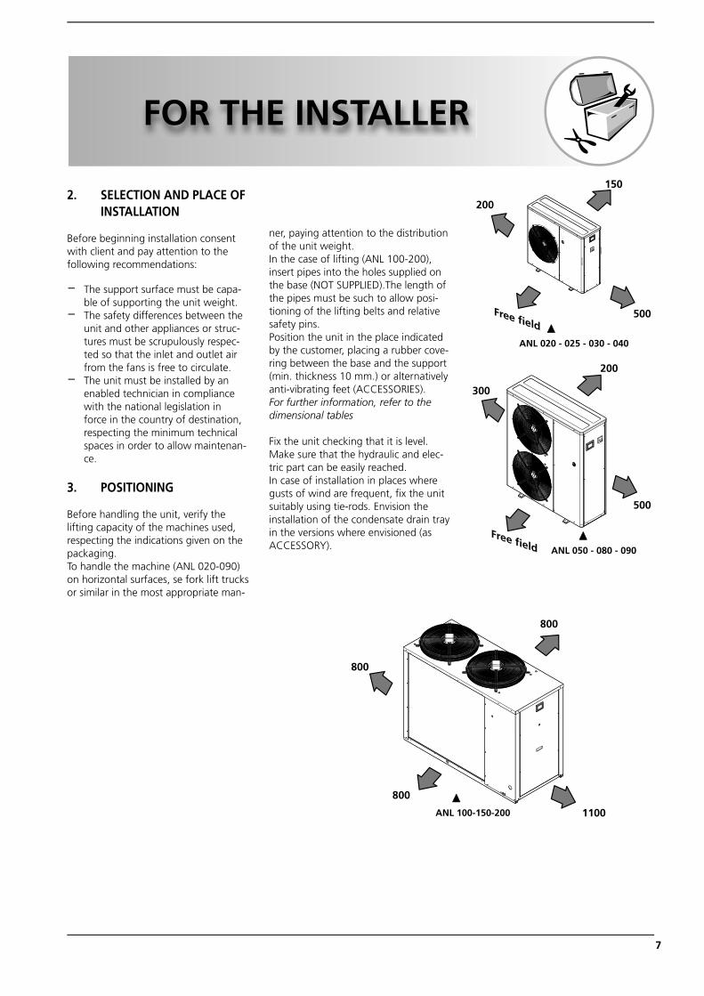
2. SELECTION AND PLACE OF INSTALLATION
Before beginning installation consent with client and pay attention to the following recommendations:
− The support surface must be capa-ble of supporting the unit weight.
− The safety differences between the unit and other appliances or struc-tures must be scrupulously respec-ted so that the inlet and outlet air from the fans is free to circulate.
− The unit must be installed by an enabled technician in compliance with the national legislation in force in the country of destination, respecting the minimum technical spaces in order to allow maintenan-ce.
3. POSITIONING
Before handling the unit, verify the lifting capacity of the machines used, respecting the indications given on the packaging. To handle the machine (ANL 020-090) on horizontal surfaces, se fork lift trucks or similar in the most appropriate man-
ner, paying attention to the distribution of the unit weight.In the case of lifting (ANL 100-200), insert pipes into the holes supplied on the base (NOT SUPPLIED).The length of the pipes must be such to allow posi-tioning of the lifting belts and relative safety pins.Position the unit in the place indicated by the customer, placing a rubber cove-ring between the base and the support (min. thickness 10 mm.) or alternatively anti-vibrating feet (ACCESSORIES). For further information, refer to the dimensional tables
Fix the unit checking that it is level. Make sure that the hydraulic and elec-tric part can be easily reached. In case of installation in places where gusts of wind are frequent, fix the unit suitably using tie-rods. Envision the installation of the condensate drain tray in the versions where envisioned (as ACCESSORY).
ANL 020 - 025 - 030 - 040
ANL 050 - 080 - 090
ANL 100-150-200
200
150
200
500
500
Free field
Free field
300
1100
800
800
800
ANL_INSTALLAZIONE riduzione costi_UK.indd 7 05/06/2009 10.35.51
8
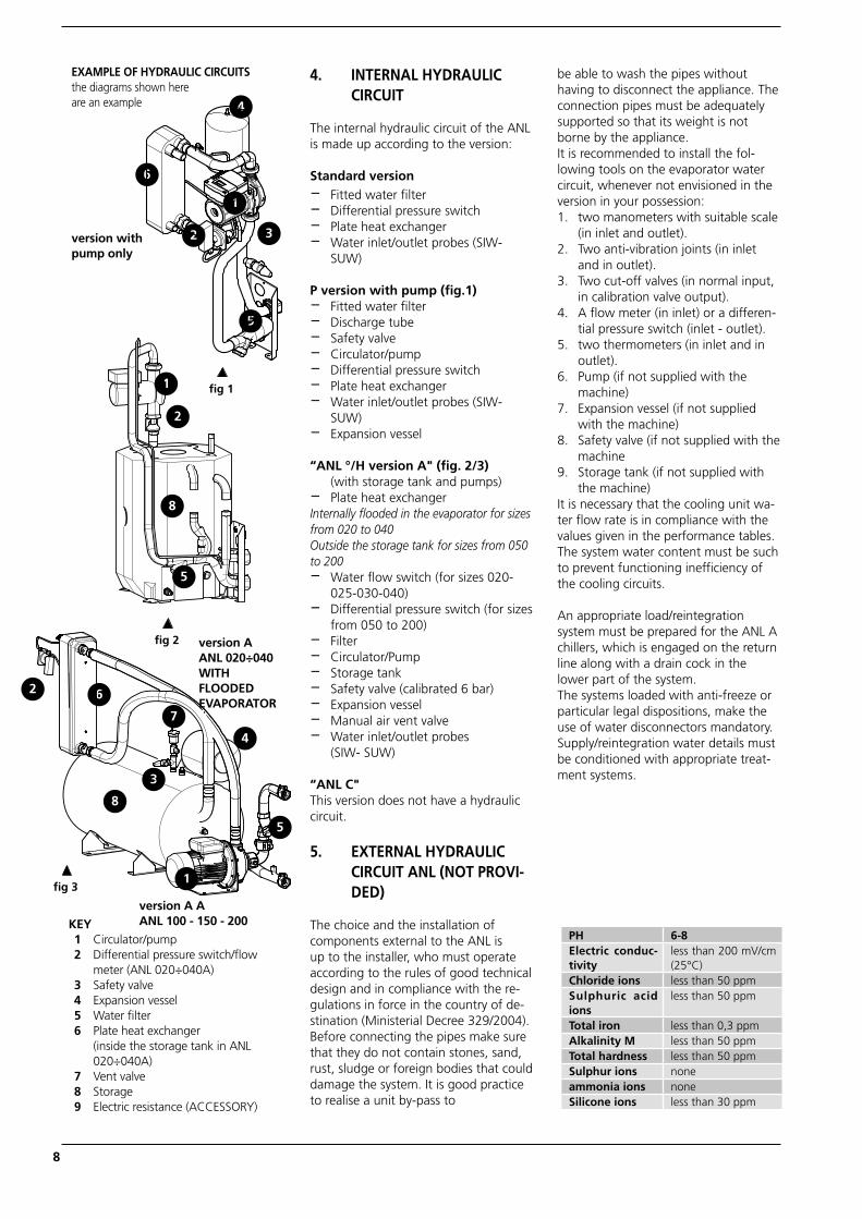
4. INTERNAL HYDRAULIC CIRCUIT
The internal hydraulic circuit of the ANL is made up according to the version:
Standard version− Fitted water fi lter− Differential pressure switch− Plate heat exchanger− Water inlet/outlet probes (SIW-
SUW)
P version with pump (fig.1)− Fitted water fi lter− Discharge tube− Safety valve − Circulator/pump− Differential pressure switch− Plate heat exchanger− Water inlet/outlet probes (SIW-
SUW)− Expansion vessel
“ANL °/H version A" (fig. 2/3) (with storage tank and pumps)− Plate heat exchanger Internally flooded in the evaporator for sizes from 020 to 040 Outside the storage tank for sizes from 050 to 200− Water fl ow switch (for sizes 020-
025-030-040)− Differential pressure switch (for sizes
from 050 to 200)− Filter− Circulator/Pump− Storage tank− Safety valve (calibrated 6 bar)− Expansion vessel− Manual air vent valve− Water inlet/outlet probes
(SIW- SUW)
“ANL C"This version does not have a hydraulic circuit.
5. EXTERNAL HYDRAULIC CIRCUIT ANL (NOT PROVI-DED)
The choice and the installation of components external to the ANL is up to the installer, who must operate according to the rules of good technical design and in compliance with the re-gulations in force in the country of de-stination (Ministerial Decree 329/2004). Before connecting the pipes make sure that they do not contain stones, sand, rust, sludge or foreign bodies that could damage the system. It is good practice to realise a unit by-pass to
be able to wash the pipes without having to disconnect the appliance. The connection pipes must be adequately supported so that its weight is not borne by the appliance. It is recommended to install the fol-lowing tools on the evaporator water circuit, whenever not envisioned in the version in your possession:1. two manometers with suitable scale (in inlet and outlet).2. Two anti-vibration joints (in inlet
and in outlet).3. Two cut-off valves (in normal input,
in calibration valve output).4. A flow meter (in inlet) or a differen-
tial pressure switch (inlet - outlet).5. two thermometers (in inlet and in
outlet).6. Pump (if not supplied with the
machine)7. Expansion vessel (if not supplied
with the machine)8. Safety valve (if not supplied with the
machine9. Storage tank (if not supplied with
the machine)It is necessary that the cooling unit wa-ter flow rate is in compliance with the values given in the performance tables.The system water content must be such to prevent functioning inefficiency of the cooling circuits.
An appropriate load/reintegration system must be prepared for the ANL A chillers, which is engaged on the return line along with a drain cock in the lower part of the system. The systems loaded with anti-freeze or particular legal dispositions, make the use of water disconnectors mandatory.Supply/reintegration water details must be conditioned with appropriate treat-ment systems.
version with pump only
EXAMPLE OF HYDRAULIC CIRCUITSthe diagrams shown here are an example
version A ANL 020÷040WITH FLOODED EVAPORATOR
KEY 1 Circulator/pump 2 Differential pressure switch/flow
meter (ANL 020÷040A) 3 Safety valve 4 Expansion vessel 5 Water filter 6 Plate heat exchanger (inside the storage tank in ANL
020÷040A) 7 Vent valve 8 Storage 9 Electric resistance (ACCESSORY)
version A A ANL 100 - 150 - 200
1
2 3
4
5
6
2
1
5
8
1
2
3
4
5
6
7
8
PH 6-8Electric conduc-tivity
less than 200 mV/cm (25°C)
Chloride ions less than 50 ppmSulphuric acid ions
less than 50 ppm
Total iron less than 0,3 ppmAlkalinity M less than 50 ppmTotal hardness less than 50 ppmSulphur ions noneammonia ions noneSilicone ions less than 30 ppm
fig 1
fig 2
fig 3
ANL_INSTALLAZIONE riduzione costi_UK.indd 8 05/06/2009 10.35.53
9
6. LOADING THE SYSTEM
− Before starting loading, check that the system drain cock is closed.
− Open all system vent valves and relative terminals.
− Open the system cut-off devices.− Start fi lling by slowly opening the
system water loading cock outside the appliance.
− When water starts to escape from the terminal vent valves, close them and continue loading until
− the value of 1.5 bar is read on the manometer.
−−The system must be loaded at a pres-
sure between 1 and 2 bar.−It is recommended to repeat this
operation after the appliance has functioned for a few hours and to periodically check the system pres-sure, reintegrating it
−if it falls below 1 bar.−Check the hydraulic sealing of the
joints.
7. EMPTYING THE SYSTEM
− Before beginning emptying, place the master switch at "OFF"
− Check that loading/water system reintegration cock is closed
− Open the drain cock outside the appliance and all system vent valves and relative terminals.
If anti-freeze is used by the unit, it must not be dumped as it is harm-ful to the environment. It should be collected and if possible reused.
If discharge takes place after fun-ctioning in heat pump mode, pay attention to the temperature of the water (also 50°).
ANL_INSTALLAZIONE riduzione costi_UK.indd 9 05/06/2009 10.35.56
10
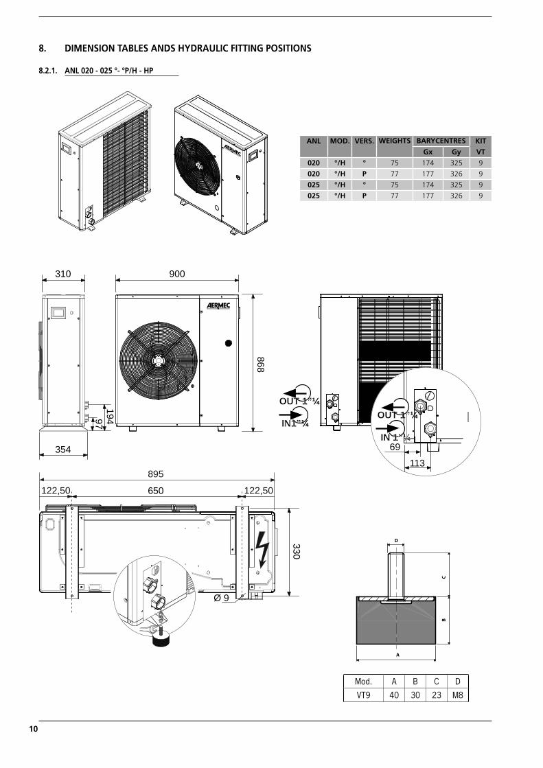
868
19497354
310 900
69
113
IN 1”¼
OUT 1”¼OUT 1”¼
IN1”¼
650
330
Ø 9
895
122,50 122,50
8. DIMENSION TABLES ANDS HYDRAULIC FITTING POSITIONS
8.2.1. ANL 020 - 025 °- °P/H - HP
A
D
CB
Mod. A B C D
VT9 40 30 23 M8
ANL MOD. VERS. WEIGHTS BARYCENTRES KIT
VTGx Gy
020 °/H ° 75 174 325 9
020 °/H P 77 177 326 9
025 °/H ° 75 174 325 9
025 °/H P 77 177 326 9
ANL_INSTALLAZIONE riduzione costi_UK.indd 10 05/06/2009 10.35.57
11
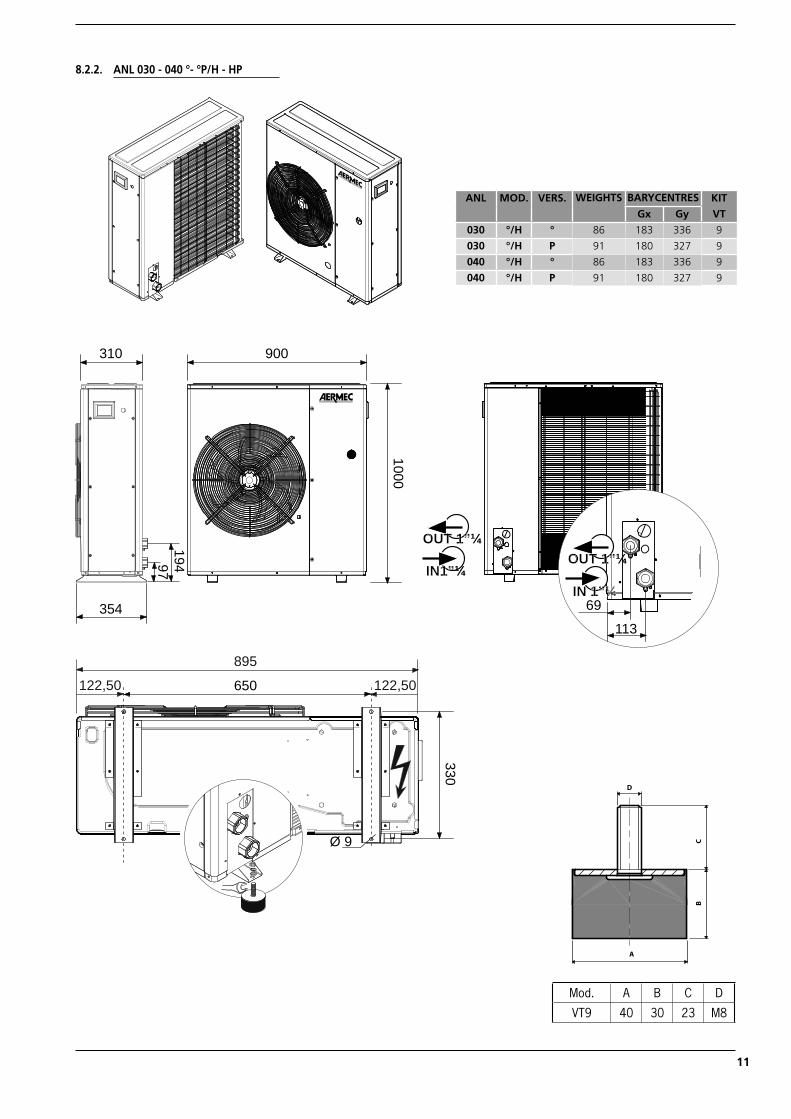
8.2.2. ANL 030 - 040 °- °P/H - HP
A
D
CB
Mod. A B C D
VT9 40 30 23 M8
1000
19497354
310 900
69
113
IN 1”¼
OUT 1”¼OUT 1”¼
IN1”¼
650
330
Ø 9
895
122,50 122,50
ANL MOD. VERS. WEIGHTS BARYCENTRES KIT
VTGx Gy
030 °/H ° 86 183 336 9
030 °/H P 91 180 327 9
040 °/H ° 86 183 336 9
040 °/H P 91 180 327 9
ANL_INSTALLAZIONE riduzione costi_UK.indd 11 05/06/2009 10.36.02
12
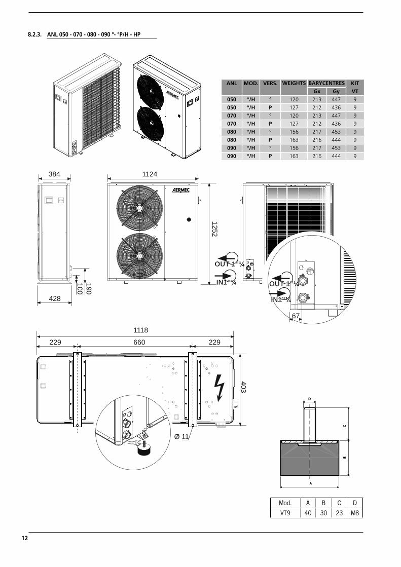
8.2.3. ANL 050 - 070 - 080 - 090 °- °P/H - HP
428
384 1124
190100
1252
OUT 1”¼
IN1”¼ OUT 1”¼
IN1”¼
67
Ø 11
660
403
1118
229 229
A
D
CB
Mod. A B C D
VT9 40 30 23 M8
ANL MOD. VERS. WEIGHTS BARYCENTRES KIT
VTGx Gy
050 °/H ° 120 213 447 9
050 °/H P 127 212 436 9
070 °/H ° 120 213 447 9
070 °/H P 127 212 436 9
080 °/H ° 156 217 453 9
080 °/H P 163 216 444 9
090 °/H ° 156 217 453 9
090 °/H P 163 216 444 9
ANL_INSTALLAZIONE riduzione costi_UK.indd 12 05/06/2009 10.36.06
13
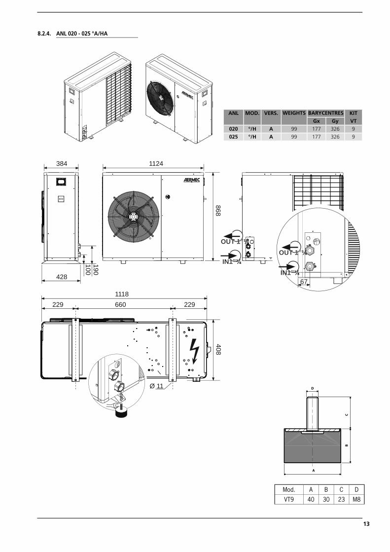
8.2.4. ANL 020 - 025 °A/HA
190100
428
384 1124868
OUT 1”¼
IN1”¼67
OUT 1”¼
IN1”¼
660229 2291118
408
Ø 11
A
D
CB
Mod. A B C D
VT9 40 30 23 M8
ANL MOD. VERS. WEIGHTS BARYCENTRES KIT
VTGx Gy
020 °/H A 99 177 326 9
025 °/H A 99 177 326 9
ANL_INSTALLAZIONE riduzione costi_UK.indd 13 05/06/2009 10.36.12
14
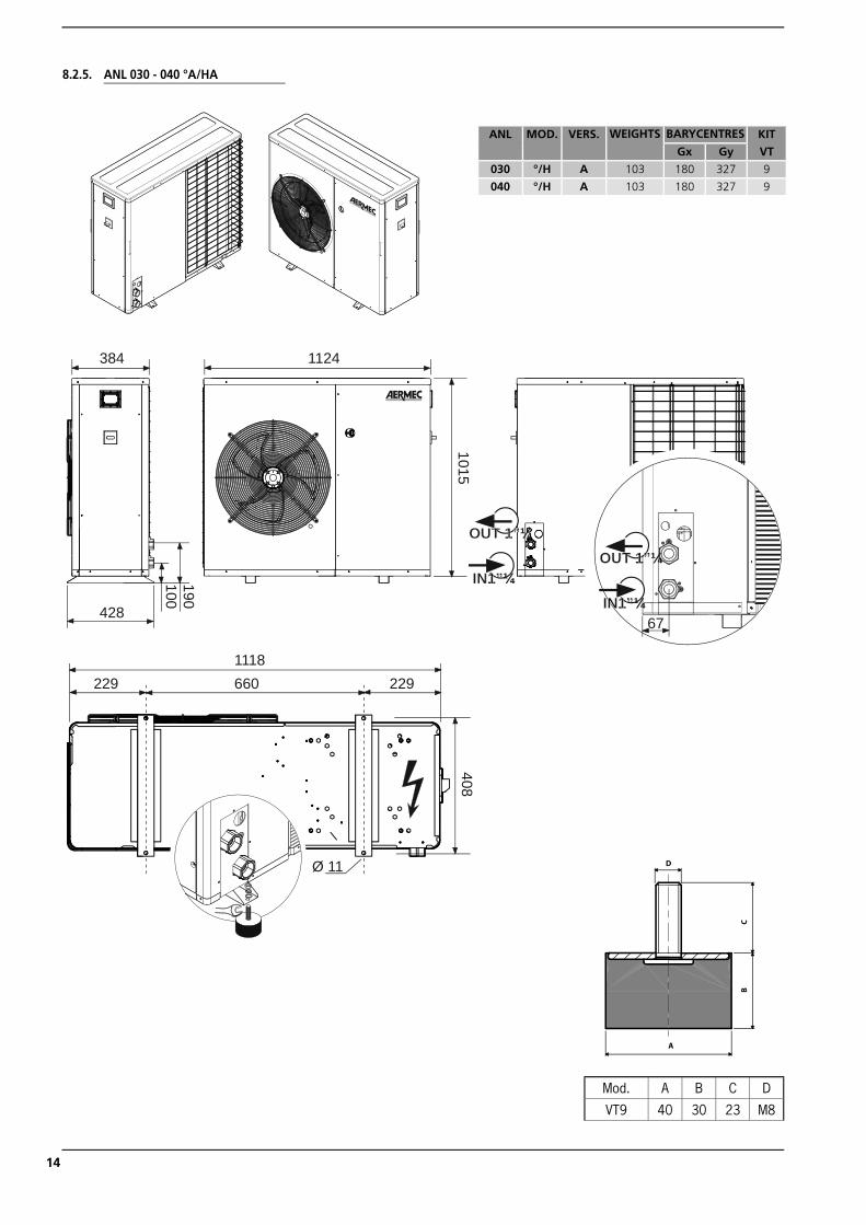
8.2.5. ANL 030 - 040 °A/HA
190100
428
384 1124
1015
OUT 1”¼
IN1”¼67
OUT 1”¼
IN1”¼
660229 2291118
408
Ø 11
ANL MOD. VERS. WEIGHTS BARYCENTRES KIT
VTGx Gy
030 °/H A 103 180 327 9
040 °/H A 103 180 327 9
A
D
CB
Mod. A B C D
VT9 40 30 23 M8
ANL_INSTALLAZIONE riduzione costi_UK.indd 14 05/06/2009 10.36.19
15
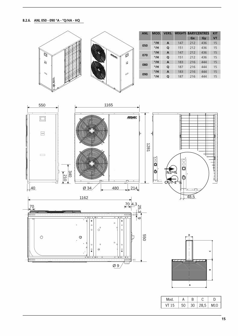
8.2.6. ANL 050 - 090 °A - °Q/HA - HQ
1165
1281
550
40 214480Ø 34
340210
48,5
OUT 1”¼
IN1”¼
Ø 9
550
70 4,370
25,39
1162
ANL MOD. VERS. WEIGHTS BARYCENTRES KIT
VTGx Gy
050°/H A 147 212 436 15
°/H Q 151 212 436 15
070°/H A 147 212 436 15
°/H Q 151 212 436 15
080°/H A 183 216 444 15
°/H Q 187 216 444 15
090°/H A 183 216 444 15
°/H Q 187 216 444 15
A
D
CB
Mod. A B C D
VT 15 50 30 28,5 M10
ANL_INSTALLAZIONE riduzione costi_UK.indd 15 05/06/2009 10.36.26
16
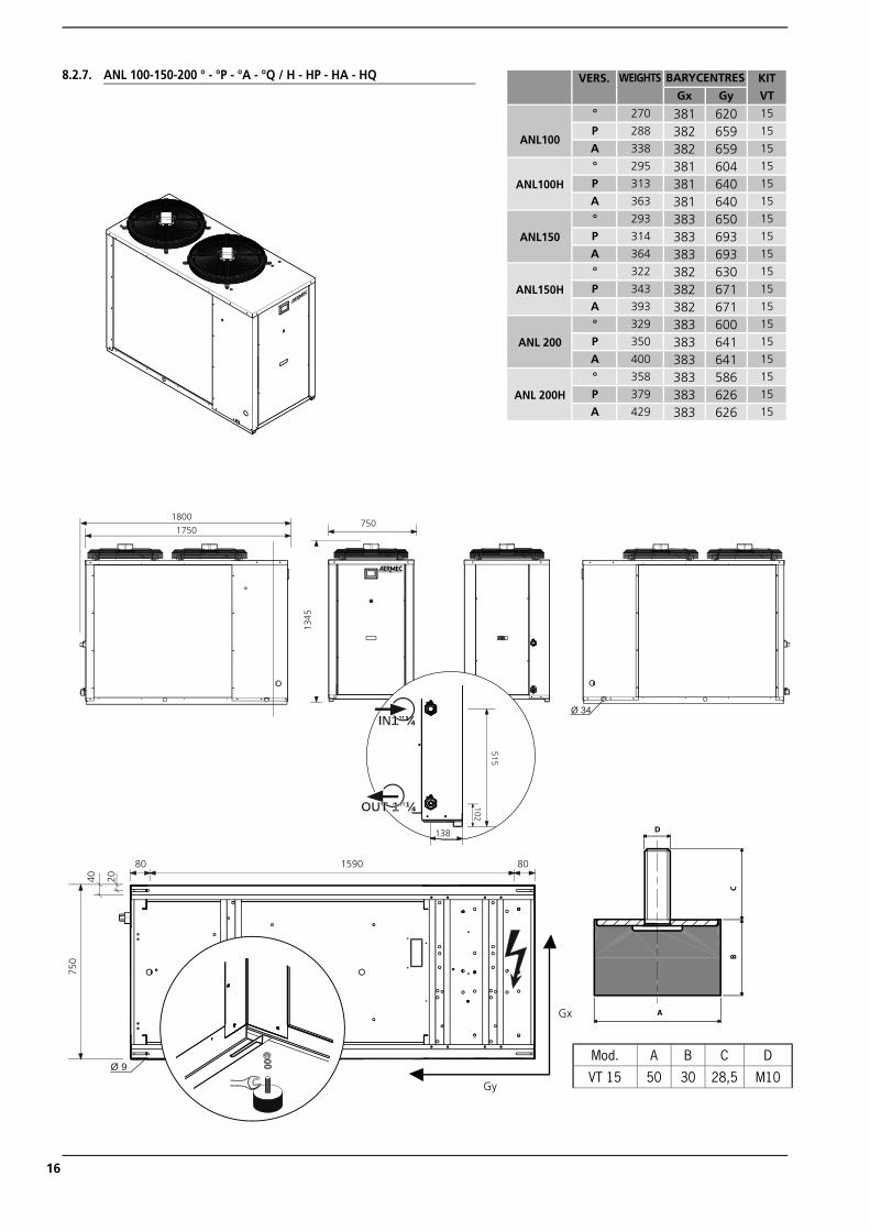
8.2.7. ANL 100-150-200 ° - °P - °A - °Q / H - HP - HA - HQ
102
515
OUT 1”¼
IN1”¼
1800
1750750
1345
Ø 34
138
80 1590 80
Ø 9
40 20
750
A
D
CB
Mod. A B C D
VT 15 50 30 28,5 M10
VERS. WEIGHTS BARYCENTRES KIT
VTGx Gy
ANL100
° 270 381 620 15
P 288 382 659 15
A 338 382 659 15
ANL100H
° 295 381 604 15
P 313 381 640 15
A 363 381 640 15
ANL150
° 293 383 650 15
P 314 383 693 15
A 364 383 693 15
ANL150H
° 322 382 630 15
P 343 382 671 15
A 393 382 671 15
ANL 200
° 329 383 600 15
P 350 383 641 15
A 400 383 641 15
ANL 200H
° 358 383 586 15
P 379 383 626 15
A 429 383 626 15
Gy
Gx
ANL_INSTALLAZIONE riduzione costi_UK.indd 16 05/06/2009 10.36.32
17
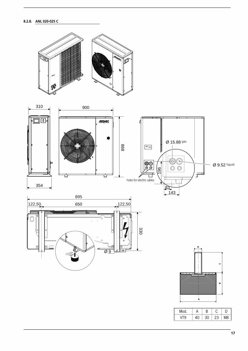
868
900
354
310
Ø 9.52 L
Ø 15.88 G
196
83143
650
330
Ø 9
895
122,50 122,50
8.2.8. ANL 020-025 C
holes for electric cables
gas
liquid
A
D
CB
Mod. A B C D
VT9 40 30 23 M8
ANL_INSTALLAZIONE riduzione costi_UK.indd 17 05/06/2009 10.36.38
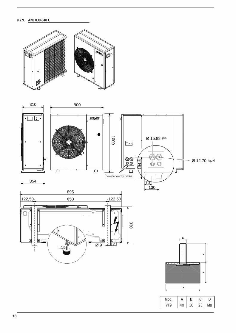
18
354
310
Ø 12.70 L
Ø 15.88 G19
4.5
70130
1000
900
650
330
Ø 9
895
122,50 122,50
8.2.9. ANL 030-040 C
holes for electric cables
gas
liquid
A
D
CB
Mod. A B C D
VT9 40 30 23 M8
ANL_INSTALLAZIONE riduzione costi_UK.indd 18 05/06/2009 10.36.42
19
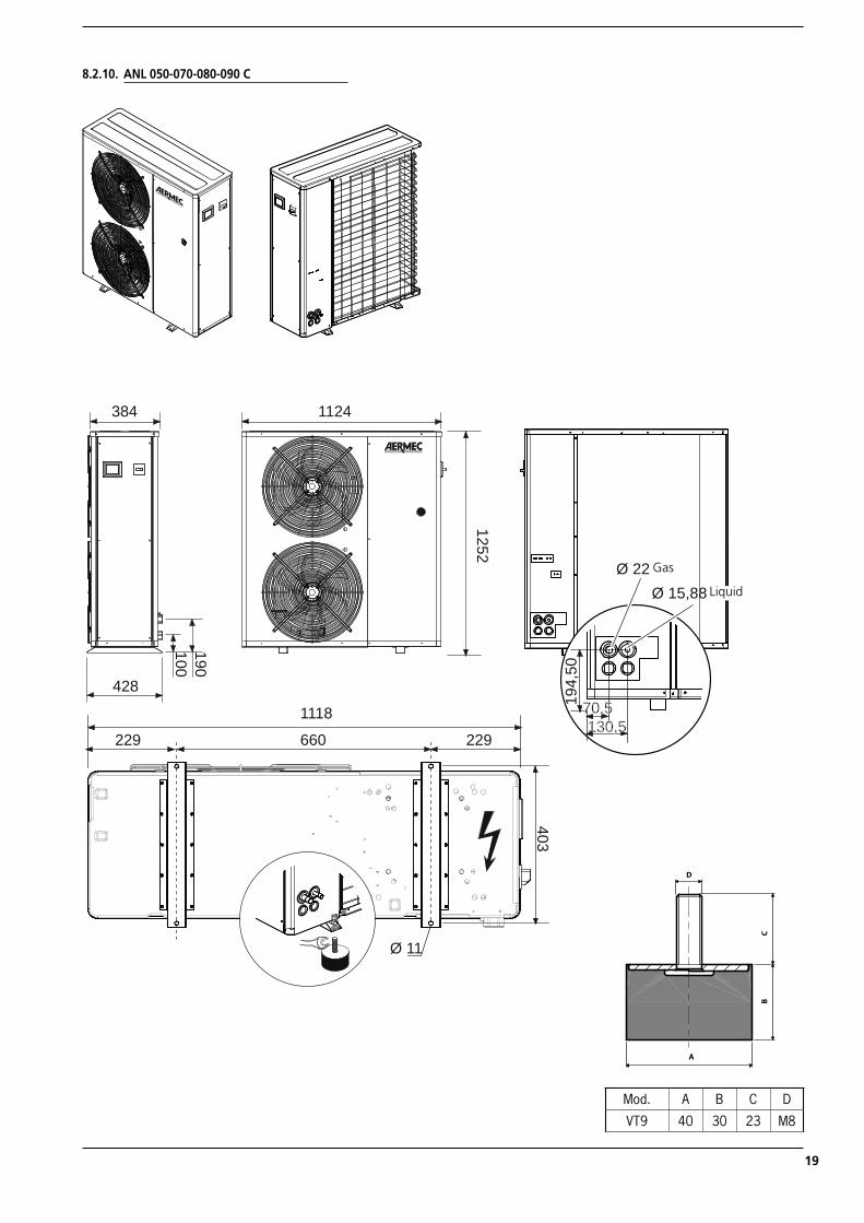
8.2.10. ANL 050-070-080-090 C
428
384 1124
190100
Ø 11
660
403
1118
229 229
1252
Ø 22 GØ 15,88 L
194,
50
70,5130,5
Gas
Liquid
A
D
CB
Mod. A B C D
VT9 40 30 23 M8
ANL_INSTALLAZIONE riduzione costi_UK.indd 19 05/06/2009 10.36.46
20
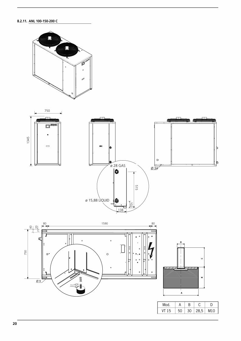
8.2.11. ANL 100-150-200 C
750
1345
Ø 34
102
515
138
Ø 28 G
Ø 15.88 L
80 1590 80
Ø 9
40 20
750
Gas
ø 15,88 LIQUID
ø 28 GAS
A
D
CB
Mod. A B C D
VT 15 50 30 28,5 M10
ANL_INSTALLAZIONE riduzione costi_UK.indd 20 05/06/2009 10.36.52
21
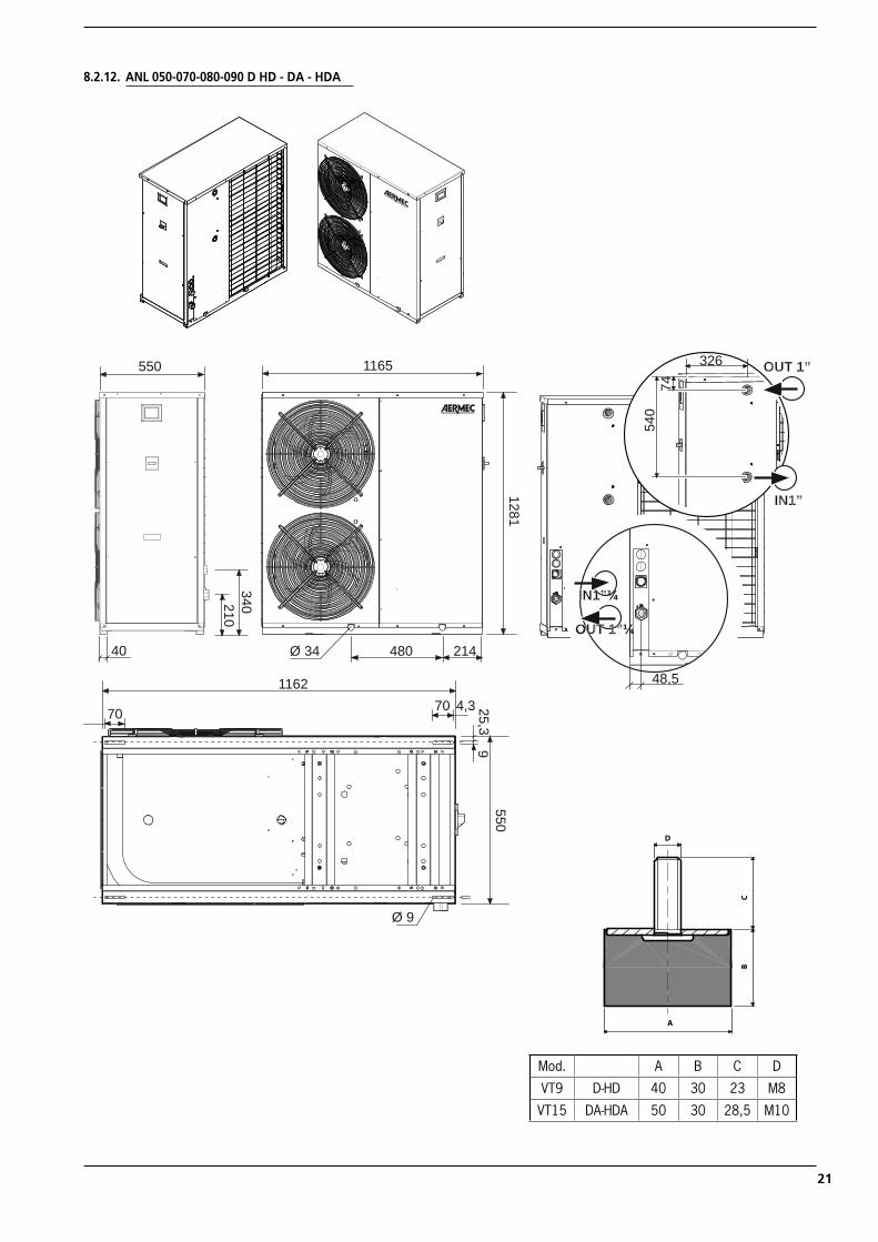
8.2.12. ANL 050-070-080-090 D HD - DA - HDA
11651281
550
40 214480Ø 34340210
Ø 9
550
70 4,370
25,39
1162 48,5
OUT 1”¼
IN1”¼
326
7454
0
IN1”
OUT 1”
A
D
CB
Mod. A B C D
VT9 D-HD 40 30 23 M8
VT15 DA-HDA 50 30 28,5 M10
ANL_INSTALLAZIONE riduzione costi_UK.indd 21 05/06/2009 10.36.57
22
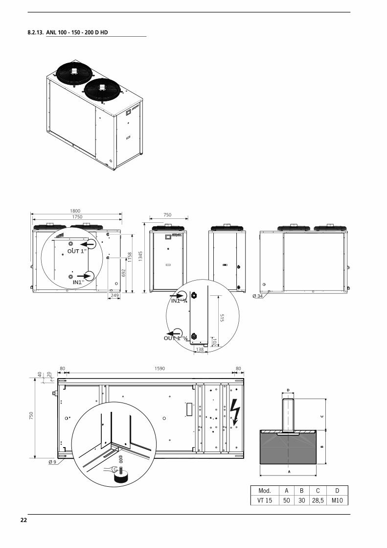
102
515
OUT 1”¼
IN1”¼
750
1345
Ø 34
138
80 1590 80
Ø 9
40 20
750
18001750
249
692
1158
OUT 1”
IN1”
8.2.13. ANL 100 - 150 - 200 D HD
A
D
CB
Mod. A B C D
VT 15 50 30 28,5 M10
ANL_INSTALLAZIONE riduzione costi_UK.indd 22 05/06/2009 10.37.03
23
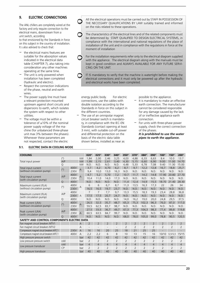
9. ELECTRIC CONNECTIONS
The ANL chillers are completely wired at the factory and only require connection to the electrical mains, downstream from aunit switch, accordingto that envisioned by the Standards in force on this subject in the country of installation. It s also advised to check that:
− the electrical mains features are suitable for the absorption values indicated in the electrical data table (CHAPTER 7), also taking into consideration any other machines operating at the same time.
− The unit is only powered when installation has been completed (hydraulic and electric).
− Respect the connection indications of the phase, neutral and earth wires.
− The power supply line must have a relevant protection mounted upstream against short circuits and dispersions to earth, which isolates the system with respect to other utilities.
− The voltage must be within a tolerance of ±10% of the nominal power supply voltage of the ma-chine (for unbalanced three-phase unit max 3% between the phases). Whenever these parameters are not respected, contact the electric
energy public body. For electric connections, use the cables with double isolation according to the Standards in force on this subject in the different countries.
− The use of an omnipolar magnet circuit breaker switch is mandato-ry, in compliance with the IEC-EN Standards (contact opening at least 3 mm), with suitable cut-off power and differential protection on the basis of the electric data table shown below, installed as near as
possible to the appliance.− It is mandatory to make an effective
earth connection. The manufacturer cannot be considered responsible for any damage caused by the lack of or ineffective appliance earth connection.
− For units with three-phase power supply, check the correct connection of the phases.
It is prohibited to use the water pipes to earth the appliance.
All the electrical operations must be carried out by STAFF IN POSSESSION OF THE NECESSARY QUALIFICATIONS BY LAW suitably trained and informed on the risks related to these operations.
The characteristics of the electrical lines and of the related components must be determined by STAFF QUALIFIED TO DESIGN ELECTRICAL SYSTEMS, in compliance with the international and national regulations of the place of installation of the unit and in compliance with the regulations in force at the moment of installation
For the installation requirements refer only to the electrical diagram supplied with the appliance. The electrical diagram along with the manuals must be kept in good condition and ALWAYS AVAILABLE FOR ANY FUTURE SERVI-CING ON THE UNIT.
IT IS mandatory to verify that the machine is watertight before making the electrical connections and it must only be powered up after the hydraulic and electrical works have been completed.
COOLING 020° 025° 030° 040° 050° 070° 080° 090° 100° 150° 200°
Total input power(°) kW 1,84 2,00 2,46 3,25 4,03 4,88 6,33 6,63 8.4 10.0 13.7A/P kW 1,99 2,15 2,61 3,40 4,30 5,15 6,60 6,90 9.00 11.00 14.70Q kW N.D. N.D. N.D. N.D. 4,48 5,33 6,78 7,08 9.40 11.30 15.00
Total input current(without circulation pump) (°)
400VA
3,7 4,2 4,70 6,2 8,7 9,7 12,2 12,8 16,7 18,8 25,7230V 9,4 10,0 13,0 16,3 N.D. N.D. N.D. N.D. N.D. N.D. N.D.
Total input current(with circulation pump)
A/P400V
A4,7 5,2 5,70 7,2 10.7 11.7 14.2 14.8 17.90 20.80 27.70
230V 10,4 11,0 14,0 17,3 N.D. N.D. N.D. N.D. N.D. N.D. N.D.Q 400V N.D. N.D. N.D. N.D. 11,4 12,4 14,9 15,5 18.70 21.40 28.30
Maximum current (FLA)(without circulation pump) (°)
400VA
6 6 6,7 8,7 11,3 13,5 16,3 17,3 22 26 34230V 16,5 16,5 19,7 23,7 N.D. N.D. N.D. N.D. N.D. N.D. N.D.
Maximum current (FLA)(with circulation pump)
A/P400V
A7 7 7,7 9,7 13,3 15,5 18,3 19,3 23,4 28,8 36,8
230V 17,5 17,5 20,7 24,7 N.D. N.D. N.D. N.D. N.D. N.D. N.D.Q 400V N.D. N.D. N.D. N.D. 14,0 16,2 19,0 20,0 24,8 29,5 37,5
Peak current (LRA)(without circulation pump) (°)
400VA
26,5 32,5 35,7 48,7 65,3 75,3 102,3 96,3 76,0 87,0 117,0230V 59,5 62,5 83,7 98,7 N.D. N.D. N.D. N.D. N.D. N.D. N.D.
Peak current (LRA)(with circulation pump)
A/P400V
A27,5 33,5 36,7 49,7 67,3 77,3 104,3 98,3 77,4 89,8 119,8
230V 60,5 63,5 84,7 99,7 N.D. N.D. N.D. N.D. N.D. N.D. N.D.Q 400V N.D. N.D. N.D. N.D. 68,0 78,0 105,0 99,0 78,8 90,5 120,5
SAFETY AND CONTROL COMPONENTS ELECTRIC DATAFan magnet circuit breakers MTV1 A 2 2 2 2 2 2 2 2 2 2 2Fan magnet circuit breakers MTV2 A - - - - 2 2 2 2 2 2 2Compressors magnet circuit breakers MTC1 230V A 16 16 20 25 18 21 25 25 - - -Compressors magnet circuit breakers MTC1 400V A 2,2 2,2 6 8 10 13 15 16 10/10 12,5/12,5 15/15High pressure pressure switch bar 42 42 42 42 42 42 42 42 42 42 42Low pressure pressure switch cold bar 2 2 2 2 2 2 2 2 2 2 2
Low pressure transducer cold bar 4 4 4 4 4 4 4 4 4 4 4CP bar 2 2 2 2 2 2 2 2 2 2 2
High pressure transducer bar 40 40 40 40 40 40 40 40 40 40 40
9.1. ELECTRIC DATA IN COOLING MODE
ANL_INSTALLAZIONE riduzione costi_UK.indd 23 05/06/2009 10.37.09
24
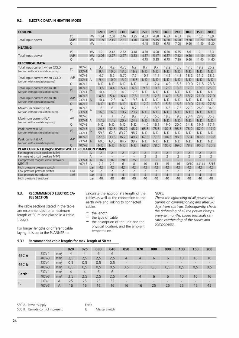
9.3. RECOMMENDED ELECTRIC CA-BLE SECTION
The cable sections stated in the table are recommended for a maximum length of 50 m and placed in a cable trough.
For longer lengths or different cable laying, it is up to the PLANNER to
calculate the appropriate length of the cables as well as the connection to the earth wire and linking to connected cables:
− the length− the type of cable− the absorption of the unit and the
physical location, and the ambient temperature.
NOTE:Check the tightening of all power wire clamps on commissioning and after 30 days from start-up. Subsequently, check the tightening of all the power clamps every six months. Loose terminals can cause overheating of the cables and components.
9.2. ELECTRIC DATA IN HEATING MODE
COOLING 020H 025H 030H 040H 050H 070H 080H 090H 100H 150H 200H
Total input power(°) kW 1,84 2,00 2,46 3,25 4,03 4,88 6,33 6,63 8,6 10,2 13,9A/P kW 1,99 2,15 2,61 3,40 4,30 5,15 6,60 6,90 9.20 11.20 14.90Q kW - - - - 4,48 5,33 6,78 7,08 9.60 11.50 15.20
HEATING
Total input power(°) kW 1,91 2,12 2,62 3,18 4,30 4,90 6,30 6,85 8,6 10,1 13,3A/P kW 2,06 2,27 2,77 3,33 4,57 5,17 6,57 7,12 9.20 11.10 14.30Q kW - - - - 4,75 5,35 6,75 7,30 9.60 11.40 14.60
ELECTRICAL DATATotal input current when COLD(version without circulation pump)
(°)400V-3
A3,7 4,2 4,70 6,2 8,7 9,7 12,2 12,8 17,0 19,2 26,2
230V-1 9,4 10,0 13,0 16,3 N.D. N.D. N.D. N.D. N.D. N.D. N.D.
Total input current when COLD(version with circulation pump)
A/P400V-3
A4,7 5,2 5,70 7,2 10,7 11,7 14,2 14,8 18.2 21.2 28.2
230V-1 9,4 10,0 13,0 16,3 N.D. N.D. N.D. N.D. N.D. N.D. N.D.Q 400V-3 N.D. N.D. N.D. N.D. 11,4 12,4 14,9 15,5 19.0 21.8 28.8
Total input current when HOT(version without circulation pump)
(°)400V-3
A 3,8 4,4 5,4 6,8 9,5 10,3 12,9 13,8 17,0 19,0 25,0230V-1 10,4 11,0 14,0 17,3 N.D. N.D. N.D. N.D. N.D. N.D. N.D.
Total input current when HOT(version with circulation pump)
A/P400V-3
A4,8 5,4 6,4 7,8 11,5 12,3 14,9 15,8 18.2 21.0 27.0
230V-1 10,4 12,3 14,0 19,3 N.D. N.D. N.D. N.D. N.D. N.D. N.D.Q 400V-3 N.D. N.D. N.D. N.D. 12,2 13,0 15,6 16,5 19.0 21.6 27.6
Maximum current (FLA)(version without circulation pump)
(°)400V-3
A6 6 6,7 8,7 11,3 13,5 16,3 17,3 22,0 26,0 34,0
230V-1 16,5 16,5 19,7 23,7 N.D. N.D. N.D. N.D. N.D. N.D. N.D.
Maximum current (FLA)(version with circulation pump)
A/P400V-3
A7 7 7,7 9,7 13,3 15,5 18,3 19,3 23.4 28.8 36.8
230V-1 17,5 17,5 20,7 24,7 N.D. N.D. N.D. N.D. N.D. N.D. N.D.Q 400V-3 N.D. N.D. N.D. N.D. 14,0 16,2 19,0 20,0 24.8 29.5 37.5
Peak current (LRA)(version without circulation pump)
(°)400V-3
A26,5 32,5 35,70 48,7 65,3 75,3 102,3 96,3 76,0 87,0 117,0
230V-1 59,5 62,5 83,70 98,7 N.D. N.D. N.D. N.D. N.D. N.D. N.D.
Peak current (LRA)(version with circulation pump)
A/P400V-3
A27,5 33,5 36,70 49,7 67,3 77,3 104,3 98,3 77,4 89,8 119,8
230V-1 60,5 63,5 84,7 99,7 N.D. N.D. N.D. N.D. N.D. N.D. N.D.Q 400V-3 N.D. N.D. N.D. N.D. 68,0 78,0 105,0 99,0 78,8 90,5 120,5
PEAK CURRENT (LRA)(VERSION WITH CIRCULATION PUMP)Fan magnet circuit breakers MTV1 A 2 2 2 2 2 2 2 2 2 2 2Fan magnet circuit breakers MTV2 A - - - - 2 2 2 2 2 2 2Compressors magnet circuit breakers MTC1/2
230V-1 A 16 16 20 25 - - - - - - -400V-3 A 2,2 2,2 6 8 10 13 15 16 10/10 12,5/12,5 15/15
High pressure pressure switch bar 42 42 42 42 42 42 42 42 42 42 42Low pressure pressure switch Cold bar 2 2 2 2 2 2 2 2 2 2 2Low pressure transducer Cold bar 4 4 4 4 4 4 4 4 4 4 4High pressure transducer bar 40 40 40 40 40 40 40 40 40 40 40
020 025 030 040 050 070 080 090 100 150 200
SEC A230V-1 mm2 4 4 6 6 - - - - - - -400V-3 mm2 2,5 2,5 2,5 2,5 4 4 6 6 10 16 16
SEC B230V-1 mm2 0,5 0,5 0,5 0,5 - - - - - - -400V-3 mm2 0,5 0,5 0,5 0,5 0,5 0,5 0,5 0,5 0,5 0,5 0,5
Earth230V-1 mm2 4 4 6 6 - - - - - - -400V-3 mm2 2,5 2,5 2,5 2,5 4 4 6 6 10 16 16
IL230V-1 A 25 25 25 32 - - - - - - -400V-3 A 16 16 16 16 16 16 25 25 25 45 45
9.3.1. Recommended cable lengths for max. length of 50 mt
SEC A Power supplySEC B Remote control if present
Earth IL Master switch
ANL_INSTALLAZIONE riduzione costi_UK.indd 24 05/06/2009 10.37.10
25
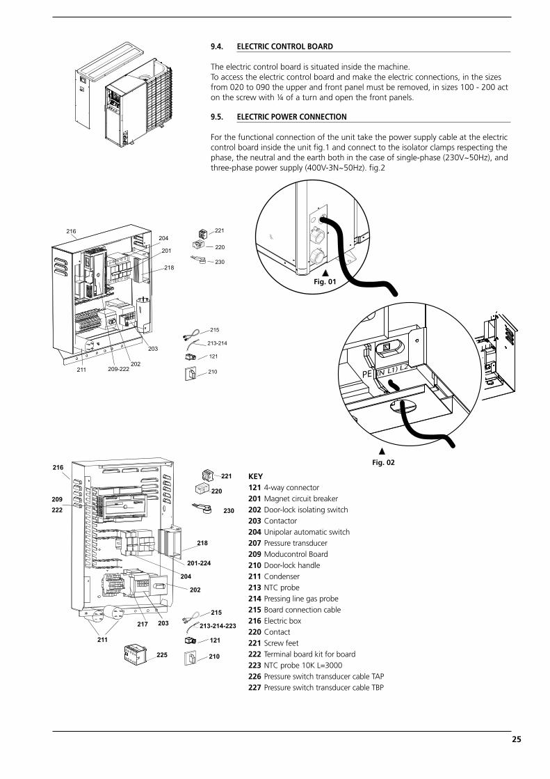
9.4. ELECTRIC CONTROL BOARD
The electric control board is situated inside the machine.To access the electric control board and make the electric connections, in the sizes from 020 to 090 the upper and front panel must be removed, in sizes 100 - 200 act on the screw with ¼ of a turn and open the front panels.
9.5. ELECTRIC POWER CONNECTION
For the functional connection of the unit take the power supply cable at the electric control board inside the unit fig.1 and connect to the isolator clamps respecting the phase, the neutral and the earth both in the case of single-phase (230V~50Hz), and three-phase power supply (400V-3N~50Hz). fig.2
KEY 121 4-way connector201 Magnet circuit breaker202 Door-lock isolating switch203 Contactor204 Unipolar automatic switch207 Pressure transducer 209 Moducontrol Board210 Door-lock handle211 Condenser213 NTC probe214 Pressing line gas probe 215 Board connection cable216 Electric box220 Contact221 Screw feet222 Terminal board kit for board223 NTC probe 10K L=3000226 Pressure switch transducer cable TAP227 Pressure switch transducer cable TBP
Fig. 01
Fig. 02
ANL_INSTALLAZIONE riduzione costi_UK.indd 25 05/06/2009 10.37.10
26
AE-N
15V
0VC/F
IACOM
AE-L
10
ALA
RM
T T T T
MAX 1A230V PR3
7 6 5 4 3 2 1
max 150mSEZ. MIN. 0.5 mm²
C/F IA
AE
max 150mSEZ. MIN. 0.5 mm²
TRA
TWS
TRA
TWS
ATTENZIONE!
tutti gli altri forniscono un'isolamento rinforzato .rispetto all'alimentazione della macchina,I morsetti 6 e 7 forniscono un'isolamento principale 3.2
3.3 3.3 2.82.5
3.43.4
3.33.2
3.23.2
M7S-5
M7S-7
M7S-8
M1-8
M1S-8
M5S1
-1M5
S1-2
M7-6M7-5
M7S-4M7S-3
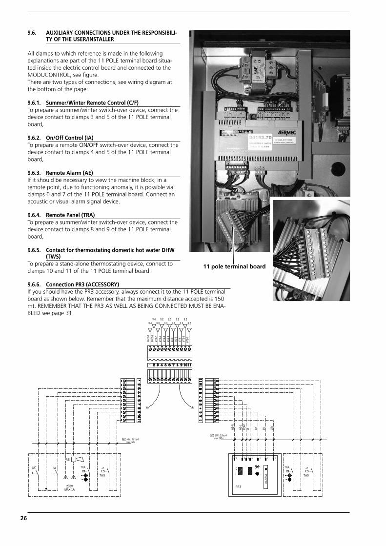
9.6. AUXILIARY CONNECTIONS UNDER THE RESPONSIBILI-TY OF THE USER/INSTALLER
All clamps to which reference is made in the following explanations are part of the 11 POLE terminal board situa-ted inside the electric control board and connected to the MODUCONTROL, see figure.There are two types of connections, see wiring diagram at the bottom of the page:
9.6.1. Summer/Winter Remote Control (C/F)To prepare a summer/winter switch-over device, connect the device contact to clamps 3 and 5 of the 11 POLE terminal board,
9.6.2. On/Off Control (IA)To prepare a remote ON/OFF switch-over device, connect the device contact to clamps 4 and 5 of the 11 POLE terminal board,
9.6.3. Remote Alarm (AE) If it should be necessary to view the machine block, in a remote point, due to functioning anomaly, it is possible via clamps 6 and 7 of the 11 POLE terminal board. Connect an acoustic or visual alarm signal device.
9.6.4. Remote Panel (TRA)To prepare a summer/winter switch-over device, connect the device contact to clamps 8 and 9 of the 11 POLE terminal board,
9.6.5. Contact for thermostating domestic hot water DHW (TWS)
To prepare a stand-alone thermostating device, connect to clamps 10 and 11 of the 11 POLE terminal board.
9.6.6. Connection PR3 (ACCESSORY)If you should have the PR3 accessory, always connect it to the 11 POLE terminal board as shown below. Remember that the maximum distance accepted is 150 mt. REMEMBER THAT THE PR3 AS WELL AS BEING CONNECTED MUST BE ENA-BLED see page 31
11 pole terminal board
ANL_INSTALLAZIONE riduzione costi_UK.indd 26 05/06/2009 10.37.11
27
10. CONTROL AND COMMIS-SIONING
10.1. PREPARATION FOR COMMISSIO-NING
Please note that, on request by the Aermec customer or the legitimate owner of the machine, the units in this series can be started up by the AERMEC After-Sales Service in your area (valid only on Italian territory).The start of operation must be schedu-led in advance based on the timeframe for the completion of works for the system. Prior to the work to be carried out by the AERMEC After-Sales Service, all other works (electrical and hydraulic connections, loading and bleeding of air from the system) must have been completed.
Before starting the unit make sure that:
− All safety conditions have been respected
− The unit is correctly fi xed to the support surface
− The minimum technical spaces have been respected;
− The hydraulic connections have been made respecting the inlet and outlet
− The hydraulic plant has been loaded and bled.
− The hydraulic circuit cocks are open
− The electric connections have been made correctly
− The voltage is within the toleran-ce of 10% of the unit nominal value
− The earth connection has been made correctly
− All electric and hydraulic connec-tions have been tightened well.
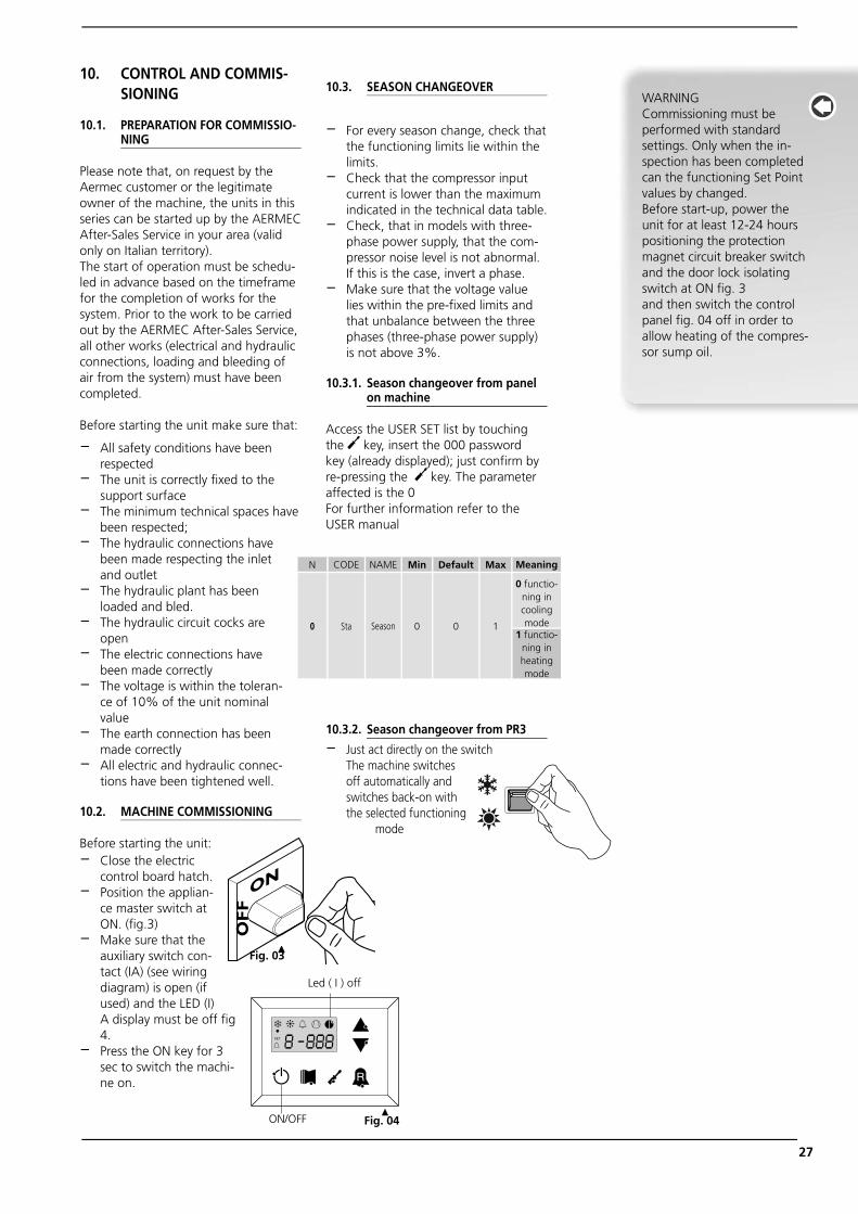
10.2. MACHINE COMMISSIONING
Before starting the unit:− Close the electric
control board hatch.− Position the applian-
ce master switch at ON. (fi g.3)
− Make sure that the auxiliary switch con-tact (IA) (see wiring diagram) is open (if used) and the LED (I) A display must be off fi g 4.
− Press the ON key for 3 sec to switch the machi-ne on.
10.3. SEASON CHANGEOVER
− For every season change, check that the functioning limits lie within the limits.
− Check that the compressor input current is lower than the maximum indicated in the technical data table.
− Check, that in models with three-phase power supply, that the com-pressor noise level is not abnormal. If this is the case, invert a phase.
− Make sure that the voltage value lies within the pre-fi xed limits and that unbalance between the three phases (three-phase power supply) is not above 3%.
10.3.1. Season changeover from panel on machine
Access the USER SET list by touching the key, insert the 000 password key (already displayed); just confirm by re-pressing the key. The parameter affected is the 0For further information refer to the USER manual
10.3.2. Season changeover from PR3
− Just act directly on the switch The machine switches
off automatically and switches back-on with the selected functioning
mode
WARNINGCommissioning must be performed with standard settings. Only when the in-spection has been completed can the functioning Set Point values by changed. Before start-up, power the unit for at least 12-24 hourspositioning the protection magnet circuit breaker switch and the door lock isolating switch at ON fi g. 3and then switch the control panel fi g. 04 off in order to allow heating of the compres-sor sump oil.
ON
OFF
Fig. 03
N CODE NAME Min Default Max Meaning
0 Sta Season 0 0 1
0 functio-ning in cooling mode
1 functio-ning in heating mode
Led ( I ) off
ON/OFF Fig. 04
ANL_INSTALLAZIONE riduzione costi_UK.indd 27 05/06/2009 10.37.16
28
11. FUNCTIONING FEATURES
11.1. SET POINT IN COOLING MODE
(factory set) = 7°C, t = 5°C.
11.2. SET POINT IN HEATING MODE
(factory set) = 45°C, t = 5°C.If the unit power supply is restored after a temporary interruption, the set mode will be kept in the memory.
11.3. COMPRESSOR START-UP DELAY
Two functions have been prepared to pre-vent compressor start-ups that are too close.
− Minimum time from last switch-off 180 seconds.
− Minimum time from last switch-on 300 seconds.
11.4. CIRCULATION PUMP
The circuit board envisions an output for pump management, which starts on commissioning and remains on for at least 150 seconds and controls the state of the probes.After the first 40 seconds that the pump functions, when the water flow rate is in normal working conditions, the water flow rate alarm functions are activated (differen-tial pressure switch or flow meter).
When the machine enters stand-by mode, the pump remains on for 30 sec and con-trols the flow meter or the pressure switch
11.5. FAN SPEED CONTROL (DCPX ACCESSORY)
To allow correct functioning of the unit at different external temperatures, the MODUCONTROL by reading the pressure via the pressure probe, controls the rotation speed of the fans, thus allowing to increase and/or decrease heat exchange, keeping the condensation or evaporation pressures more or less constant. The fan functions indepen-dently with respect to the compressor.Remember that the DCPX is mandatory for the production of DHW
11.6. ANTI-FREEZE ALARM
The anti-freeze alarm is never active if the machine is off or in stand-by mode. In order to prevent breakage of the plate heat exchanger due to freezing of the water it contains, the MODUCONTROL blocks the compressor and ignition of the resistance (ACCESSORY) if the temperature detected by the probe positioned at the outlet of the heat exchanger and in inlet to the chiller is below +4°C.THIS ANTI-FREEZE SET TEMPERATURE CAN ONLY BE VARIED BY AN AUTHORISED AFTER-SALES CENTRE AND ONLY AFTER HA-VING CHECKED THAT THERE IS ANTI-FREEZE
SOLUTION IN THE WATER SYSTEM.The intervention of this alarm determines compressor block and not pump block, which remains active along with the switch-on of the resistance if installed.To restore normal functions the temperature of the outlet water must rise above +4°C. Rearm is manual.WHENEVER THIS ALARM INTERVENES, WE ADVISE YOU CALL THE NEAREST AFTER-SALES SERVICE IMMEDIATELY.
11.7. WATER FLOW RATE ALARM
The MODUCONTROL manages a water flow rate alarm controlled by the differential pressure switch installed in series on the machine.This type of safety device intervenes after the first 40 seconds of pump functioning, if the water flow rate is not sufficient.The intervention of this alarm determines compressor and pump block.
12. MAINTENANCE
All cleaning is prohibited until the unit has been disconnected from the electric power supply mains.Make sure there is no voltage present before operating.Periodic maintenance is fundamental to keep the unit perfectly efficient under a functional and energetic point of view. It is therefore essential to carry out periodic yearly controls for the:
12.7.1. Hydraulic circuit− Refi lling of water circuit− Cleaning the water fi lter − Control of fl ow switch/pressure switch− Bleed the air from the circuit.− Verify that the water fl ow rate to the evapo-
rator is constant.− Verify the thermal insulation of the hydraulic
piping.− Check the percentage of glycol where neces-
sary
12.7.2. Electric circuit checks− Safety effi ciency− Electric supply pressure − Electrical Input− Connection tightness− Verify the operation of the carter compressor
resistance
12.7.3. Cooling circuit checks− State of compressor− Effi ciency of the plate heat exchanger resi-
stance if envisioned − Work pressure− Leak test for watertightness control of the
cooling circuit− Functioning of high and low pressure pressu-
re switches − Carry out the appropriate checks on the fi lter
dryer to check effi ciency
12.7.4. Mechanical checks− Check the tightening of the screws the
compressors and the electrical box, as well as the exterior panelling of the unit. Insuffi cient fastening can lead to undesired noise and
WARNINGInspection, maintenance and eventual repair work must be car-ried out only by a legally qualified technician.
Lack of control/maintenance can cause damage to persons or things.
For appliances installed near to the sea, the maintenance inter-vals must be halved.
ANL_INSTALLAZIONE riduzione costi_UK.indd 28 05/06/2009 10.37.17
29
vibrations− Check the condition of the structure.
If there are any oxidised parts, treat with paint suitable to eliminate or reduce oxidation.
12.1. EXTRAORDINARY MAINTENANCE
the ANLs are fi lled with R410A gas and are inspected at the factory. Under normal conditions they do not require Technical Assistance related to control of refrigerant gas. Through time gas leakage may be ge-nerated from the joints, causing refrigerant to escape and discharge the circuit, causing appliance malfunctioning. In these cases the leakage points are to be discovered, repai-red and the Gas circuit is to be replenished, respecting the December 28 1993 n°549 law.
12.1.1. Load procedure
The load procedure is the following:− Empty and dry the entire cooling circuit
using a vacuum pump connected to the low and high pressure socket until 10 Pa is read on the vacuum meter. Wait a few minutes and check that this value does not rise above 50 Pa.
− Connect the refrigerant gas cylinder or a load cylinder to the socket on the low pressure line.
− Load the amount of refrigerant gas indi-cated on the appliance features plate.
− After a few hours of functioning, check
that the liquid indicator indicates the dry circuit (dry-green). In the case of partial loss, the circuit must be emptied completely before being re-loaded.
− The R410A refrigerant must only be loaded in the liquid state.
− Functioning conditions that are different to the nominal conditions can give rise to values that are greatly different.
− The sealing test or the search for leaks must only be performed using R410A refrigerant gas, checking using a suita-ble leak detector.
− In the cooling circuit it is prohibited to use oxygen or acetylene or other infl am-mable or poisonous gases because they are a cause of explosions or intoxica-tion. We recommend to envision a ma-chine book (not supplied, but the user's responsibility), which allows to keep track of the interventions performed on the unit. In this way it will be easy to suitably organise the interventions making research and the prevention of any machine breakdowns easier.
− Use the date to record date, type of in-tervention made (routine maintenance, inspection or repairs), description of the intervention, measures actuated…
− IT IS forbidden to RELOAD the circuit with a refrigerant gas different to the one indicated. Using a different refrige-rant gas can cause serious damage to the compressor.
We recommend to envision a machine book (not supplied, but the user's responsibility), which allows to keep track of the interventions performed on the unit. In this way it will be easy to suitably organise the interven-tions making research and the prevention of any machine brea-kdowns easier.Use the date to record date, type of intervention made (routine maintenance, inspection or repai-rs), description of the interven-tion, measures actuated…
IT IS forbidden to RELOAD the circuit with a refrigerant gas different to the one indicated. Using a different refrigerant gas can cause serious damage to the compressor.
DISPOSAL Envisions that disposal of the unit is carried out in conformity with the Standards in force in the different countries
ANL_INSTALLAZIONE riduzione costi_UK.indd 29 05/06/2009 10.37.17
30
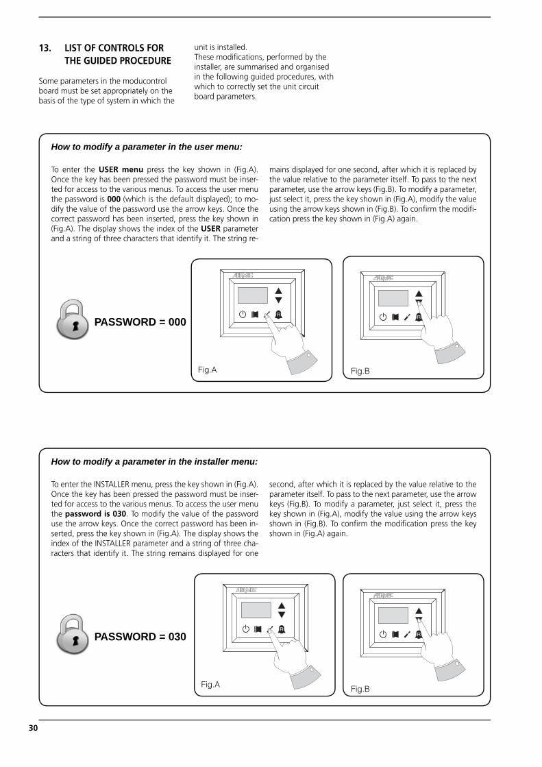
13. LIST OF CONTROLS FOR THE GUIDED PROCEDURE
Some parameters in the moducontrol board must be set appropriately on the basis of the type of system in which the
unit is installed.These modifi cations, performed by the installer, are summarised and organised in the following guided procedures, with which to correctly set the unit circuit board parameters.
To enter the USER menu press the key shown in (Fig.A). Once the key has been pressed the password must be inser-ted for access to the various menus. To access the user menu the password is 000 (which is the default displayed); to mo-dify the value of the password use the arrow keys. Once the correct password has been inserted, press the key shown in (Fig.A). The display shows the index of the USER parameter and a string of three characters that identify it. The string re-
mains displayed for one second, after which it is replaced by the value relative to the parameter itself. To pass to the next parameter, use the arrow keys (Fig.B). To modify a parameter, just select it, press the key shown in (Fig.A), modify the value using the arrow keys shown in (Fig.B). To confi rm the modifi -cation press the key shown in (Fig.A) again.
�
Fig.A Fig.B
�PASSWORD = 000
How to modify a parameter in the user menu:
To enter the INSTALLER menu, press the key shown in (Fig.A). Once the key has been pressed the password must be inser-ted for access to the various menus. To access the user menu the password is 030. To modify the value of the password use the arrow keys. Once the correct password has been in-serted, press the key shown in (Fig.A). The display shows the index of the INSTALLER parameter and a string of three cha-racters that identify it. The string remains displayed for one
second, after which it is replaced by the value relative to the parameter itself. To pass to the next parameter, use the arrow keys (Fig.B). To modify a parameter, just select it, press the key shown in (Fig.A), modify the value using the arrow keys shown in (Fig.B). To confi rm the modifi cation press the key shown in (Fig.A) again.
�
Fig.A Fig.B
�PASSWORD = 030
How to modify a parameter in the installer menu:
ANL_INSTALLAZIONE riduzione costi_UK.indd 30 05/06/2009 10.37.18
31
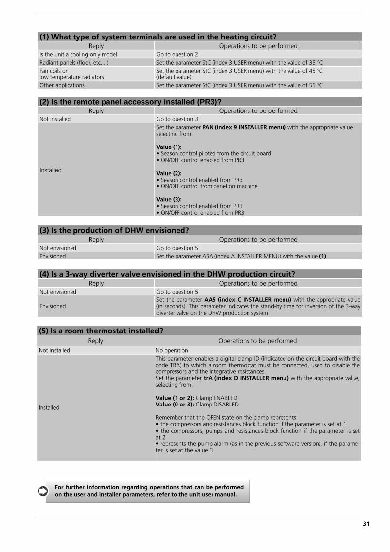
(1) What type of system terminals are used in the heating circuit?Reply Operations to be performed
Is the unit a cooling only model Go to question 2Radiant panels (fl oor, etc....) Set the parameter StC (index 3 USER menu) with the value of 35 °CFan coils or low temperature radiators
Set the parameter StC (index 3 USER menu) with the value of 45 °C (default value)
Other applications Set the parameter StC (index 3 USER menu) with the value of 55 °C
(2) Is the remote panel accessory installed (PR3)?Reply Operations to be performed
Not installed Go to question 3
Installed
Set the parameter PAN (index 9 INSTALLER menu) with the appropriate value selecting from:
Value (1): • Season control piloted from the circuit board• ON/OFF control enabled from PR3 Value (2): • Season control enabled from PR3• ON/OFF control from panel on machine Value (3): • Season control enabled from PR3• ON/OFF control enabled from PR3
(3) Is the production of DHW envisioned?Reply Operations to be performed
Not envisioned Go to question 5Envisioned Set the parameter ASA (index A INSTALLER MENU) with the value (1)
(4) Is a 3-way diverter valve envisioned in the DHW production circuit?Reply Operations to be performed
Not envisioned Go to question 5
EnvisionedSet the parameter AAS (index C INSTALLER menu) with the appropriate value (in seconds). This parameter indicates the stand-by time for inversion of the 3-way diverter valve on the DHW production system
(5) Is a room thermostat installed?Reply Operations to be performed
Not installed No operation
Installed
This parameter enables a digital clamp ID (indicated on the circuit board with the code TRA) to which a room thermostat must be connected, used to disable the compressors and the integrative resistances. Set the parameter trA (index D INSTALLER menu) with the appropriate value, selecting from:
Value (1 or 2): Clamp ENABLEDValue (0 or 3): Clamp DISABLED
Remember that the OPEN state on the clamp represents:• the compressors and resistances block function if the parameter is set at 1• the compressors, pumps and resistances block function if the parameter is set at 2• represents the pump alarm (as in the previous software version), if the parame-ter is set at the value 3
For further information regarding operations that can be performed on the user and installer parameters, refer to the unit user manual.
ANL_INSTALLAZIONE riduzione costi_UK.indd 31 05/06/2009 10.37.19
32
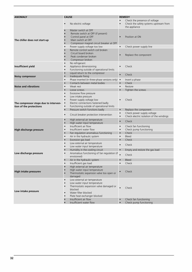
ANOMALY CAUSE REMEDY
The chiller does not start-up
• No electric voltage• Check the presence of voltage• Check the safety systems upstream from
the appliance• Master switch at OFF• Remote switch at OFF (if present)• Control panel at OFF• Main switch at OFF• Compressor magnet circuit breaker at OFF
• Position at ON
• Power supply voltage too low • Check power supply line• Remote control switch coil broken• Circuit board broken• Peak condenser broken• Compressor broken
• Replace the component
Insufficient yield• No refrigerant• Appliance dimensioning• Functioning outside of operational limits
• Check
Noisy compressor• Liquid return to the compressor• Inadequate fixing
• Check
• Phase inverted (in three-phase versions only) • Invert a phase
Noise and vibrations• Contacts between metal bodies • Check• Weak rest • Restore• Loose screws • Tighten the screws
The compressor stops due to interven-tion of the protections
• Excessive flow pressure• Low intake pressure• Power supply voltage low• Electric connections fastened badly• Functioning outside of operational limits
• Check
• Pressure switch functions badly • Replace the component
• Circuit breaker protection intervention• Check power supply voltage• Check electric isolation of the windings
High discharge pressure
• High external air temperature• High water input temperature
• Check
• Insufficient air flow• Insufficient water flow
• Check fan functioning• Check pump functioning
• Fan regulation anomalous functioning • Check• Air in the hydraulic system • Bleed• Excessive gas load • Check
Low discharge pressure
• Low external air temperature• Low water input temperature
• Check
• Humidity in the cooling circuit • Empty and restore the gas load• Anomalous functioning of fan regulation (if
envisioned)• Check
• Air in the hydraulic system • Bleed• Insufficient gas load • Check
High intake pressurev
• High external air temperature• High water input temperature• Thermostatic expansion valve too open or
damaged
• Check
Low intake pressure
• Low external air temperature• Low water input temperature• Thermostatic expansion valve damaged or
blocked• Water filter blocked• Plate heat exchanger blocked
• Check
• Insufficient air flow• Insufficient water flow
• Check fan functioning• Check pump functioning
ANL_INSTALLAZIONE riduzione costi_UK.indd 32 05/06/2009 10.37.19

33
ANL_INSTALLAZIONE riduzione costi_UK.indd 33 05/06/2009 10.37.19

34
ANL_INSTALLAZIONE riduzione costi_UK.indd 34 05/06/2009 10.37.19

35
ANL_INSTALLAZIONE riduzione costi_UK.indd 35 05/06/2009 10.37.19

The technical data given on the following documentation is not binding. Aermec reserves the right to make all the modifications deemed necessary for improving the product.
37040 Bevilacqua (VR) - ItalyVia Roma, 44 - Tel. (+39) 0442 633111Telefax (+39) 0442 93730 - (+39) 0442 93566www . aermec . com
carta reciclata recycled paperpapier recyclérecycled papier
ANL_INSTALLAZIONE riduzione costi_UK.indd 36 05/06/2009 10.37.19