and unfired pressure vessel code;...
TRANSCRIPT

WISCONSIN ADMINISTRATIVE -CODE 9
Chapter Ind 42
BOILER AND UNFIRED PRESSURE VESSEL CODE;EXISTING INSTALLATIONS
Ind 42,001 Application Ind 42,30 Flanged connectionsInd 42.005 , M a x i nr u m allowable ° `Ind 42.31 Washout and - inspection
working pressures openingsInd 42.0 1 Code constructed vessels Ind 42.32 ManholesInd 42.02 Pressure calculations for Ind 42.33 Maintenance
shells Ind 42.34 Threaded opening'sInd 42.03 Pressure calculations for Ind 42,35 Boiler setting and instal-
flat heads and flat sur- lationfaces Ind 42.36 Access and firing doors
Ind 42.04 Pressure calculations for Ind 42.37 Water tube boiler doorsdished heads Ind 42.38 Low-water cut-off and
Ind 42.05 Dished head restrictions water feederInd 4 2 .06 Pressure calculation for Ind 42.39 Safety valves, r e i i e f
furnaces and circular flues valves and connections forInd 42.07 Boiler platethickness unflred ':pressure vessels -`Ind 42.08 Secondhand boilers and Ind 42.40 Pressure relief devices on
unfi red pressure vessels unflred pressure vesselsInd 42.09 Factor of safety Ind 42.50 Rules and reportsInd 42.10 Strength of materials Ind 42.51 Hydrostatic testInd 42.11 Shearing strength of riv- Ind 42.52 'Design of riveted patches
ets Ind 42.53 Material for rivetedInd 42.12 Rivet .dimensions after patches
driving Ind 42.54 Workmanship on rivetedInd 42.13 Efficiency of joint patchesInd 42.14 Ligament between `paral- `Ind 42,55 Calculations for riveted
lel tube holes patchesInd 42.15 Ligaments between diag- Ind 42.56 Examples of calculations
onal tube holes for riveted patchesInd 42.16 ' Maximum pressure for ''Ind 42.59 Procedure
cast iron boilers Ind42.60 WeldersInd 42.17 Safety or relief valves re- Ind 42,61 Rules for welding
quired Ind 42.62 ;Prohibited repairsTnd I''.18 Safety valves for low Ind 42.63 Procedure
pressure steam, minia- Ind 42.64 Defective weldture, and power boilers Ind 42.65 Stress relieving operations
Ind 42.19 Water-relief valves for Ind 42.66 Cracks, permissiblehot water boilers welded repairs
Ind 42.20 Thermometers for hot wa- Ind 4 2.6 9 Corroded surfaces andter< boilers seal welding
Ind 42.21 Water glass Ind 42.74 Re-ending and piecing42.22 Gage cocks_Ind tubes
Ind 42.23 Water colunin piping Ind 42.75 Patches,; materialInd 42.24 Pressure gages Ind 42.76 Flush or butt weldedInd 42.25 Stop valves' on pressure - patches
discharge outlets Ind 42.78 Lapped and fillet weldedy Ind 42.26 Steam mains patches
Ind 42.27 Bottom blow-off or drain. Ind 42.79 StaysInd Feed pipe. 42.28 Ind 42.80 Additional acceptable re-Ind 42.29 Combustion regulators for pair methods
boilers
Ind 42.001 Application. The following orders shall apply to unfiredpressure vessels or boilers installed prior to January 1, 1957 andsecondhand unfired pressure vessels or boilers,*
r Note: For the installation, operation, and field' inspection of vessels usedfor the storage and transportation of liquid petroleum gases, anhydrousammonia, and all the refrigerant on aining vess Is, see the state bode,wjd h governs. ' The construction , shty^
¢i spection, a d_:repair of th de vessels.
sirll be governed by sections Ind 11,50 and Ind 41.51 and Ind 42.50. to Ind42.80 of this code.
History: Cr.' Register, December, 1956, No. 12, eff. 1-1-57.
Boiler and Unfired Pressure Vessel Code Register, December, 1956. No, 12

10 INDUSTRIAL. COMMISSION
Ind 42.005 Maximum allowable working pressures. (1) The maxi-mum allowable working pressure on a boiler
i-of-this
unfired pressurevessel is the safe pressure at which the boilerunfired pressurevessel may be operated as determined by chapter WisconsinAdministrative Code.
(2) No boiler or unfired pressure vessel shall be operated at apressure in excess of the maximum allowable working pressure for
a such boiler or unfired pressure vessel.
History: Cr. Register, December, 1956, No. 12, eff. 1-1-57.
Ind 42,01 Code constructed vessels. Any pressure vessel that hasbeen constructed and 'stamped in accordance with the rules and regu-lations of the A.S.M.E, Boiler and Pressure, Vessel_ Code, or otherrecognized codes, or has the standard stamping of another state thathas adopted the standard of construction of the A,S.M.E. 'Boiler andPressure ;Vessel' Code,, shall be allowed and may be operated at themaximum working pressure stamped on its shell providing the vesselis unaltered, in good working, order, and not deteriorated by age orcorrosion. For unstamped vessels, t e operating press^e shall bedetermined by using sections Ind 42.2 through Ind 42.'16 ` lnclusive.
History: Cr. Register, December, 1956, No.: 12, eff, 1-1-57,
Ind 42.02 Pressure calculations for shells. The maximum allowableworking pressure to be allowed on the shell of a boiler or unfired pres-sure vessel shall be determined from the following formula:
T.S.XtXER. X F.S.
where P = maximum allowable working pressure, pounds per .squareinch,
T.S. = tensile strength of shell plate, pounds per square inch,t - minimum thickness of shell plates, 'inches
E — efficiency of longitudinal joint .= method of -determiningwhich is given in section Ind 42.13..
R.= Inside radius of the outside course of the shell,' ItF.S., lowest factor of safety allowed by section Ind 42.09.
History: Cr. Register, December, 1956, No. 12, eff. 1-1-57,
Ind 42.03 'Pressure calculations for flat heads and flat surfaces. Themaximum allowable working pressure on flat surfaces of boilers andunfired pressure vessels shall be determined by the following formula:
T.S. X t'P ' 0.5 X da X F.S.
where P Maximum allowable working pressure, pounds per squareinch,
T.S.`- tensile strength of plate, pounds per square inch,t thickness of plate, inches,d:— diameter of head or shortest unsupported span of head or
maximum pitch between stays, inches,F.S. lowest factor of safety allowed by section Ind 42.09. 1/
Note: No allowance will be made for the bolding power of flanges,
History: Cr. Register, December, 1956, No. 12, eff. 1-1-57.
Boiler and Un fired Pressure Vessel Code Register, December, 1956. No. 1°

WISCONSIN ADMINISTRATIVE CODE 11
Ind 42.04 Pressure calculations for dished heads. The maximumallowable working pressure on unstayed dished heads shall be de-termined by the following formula:
Pressure on concave side (plus head)
P-2XT.S.XEXt
8.33 X L
Pressure on convex side (minus head)
2XT.S.XEXtX0.6P 8.33 X L
where t thickness of plate, inchesP maximum allowable working pressure pounds per square
inchT.S.:— tensile strength pounds per square inch
L.= radius to which the head is dished,measure on the concave side of the head, inches
E,_ efficiency of weakest joint used in forming the head(Exclusive of the joint to the shell) for seamless headsE — 1.00.
History: Cr. Register, December, 1956, No. -12,.eff. . 1-1-57.
Ind 42.05 Dished head restrictions. Dished heads without skirts orflanges shall not be used for any pressure.
History: Cr. Register, December, 1956, No. 13, eff. 1-1-57.
Ind 42.06 Pressure calculation for furnaces and circular flues. The
NOula
mum allowable working pressure on furnaces of vertical boilerscirc rrflus shall be determined as indicated in sections Ind` and Ind 41.51 of this code.
History: Cr. Register, December, 1956, No. 12, eff. 1-1-57.
Ind 42.07 Boiler plate thickness. (1) The minimum thickness ofany boiler plate under pressure shall be 1 4 inch except that boilerplate in stayed surfaces shall be 5/16 ineh thick minimum.
(2) Seamless shells for miniature boilers may be constructed of3/16 inch boiler plate.
History: Cr. tegister, December, 1956, No. 12, eff. 1-1-57.
Ind 42.08 Secondhand boilers and unfired pressure vessels. (1) AfterJanuary 1, 1957, except those covered by section Ind 42.6.1., all othersecondhand boilers and unfired pressure vessels, by which is meanta pressure vessel on which both ownership and location are changed,shall have a factor of safety of at least 6.
(2) Each secondhand pressure vessel shall be inspected and ahydrostatic pressure test applied by an authorized inspector, beforeit is installed. The hydrostatic pressure test shall be one and one-halftimes the maximum allowable working pressure.
(3) A secondhand boiler of the lap seam type larger than 36 inchesin diameter, shall be limited to :a maximum allowable working pres-sure not exceeding 15 pounds.
(4) Boilers the longitudinal joint on which is exposed to the in-tense heat of the furnace, shall not be installed for any pressure.
Note: The locomotive or 'inside welt strap will not be considered asstrengthening or 'changing the original type, of the boiler joint.
Boll ,wr and Unfired Pressure Vessel Code Register, December, 1956. No. 12

12 1INDUSTRIAL COMMISSION
(5) All secondhand pressure vessel vixen reinstall must complywith all the orders in sections Ind 41.50ry and Ind 41,31 pertaining tofittings, appliances, valves and connections and settings and supports.
(6) A portable boiler khich is brought into this state for use, shallbe inspected and shall 4e given a hydrostatic pressure test in accord-ance with subsection (2)Lof this section and the maximum allowableworking pressure shall be determine by using the correct factorof safety according to section Ind 42.09.
History; Cr. Register, December, 1956, No. 12, eff. 1-1-57.
Ind 42.09 Factor of safety. Maximum aljae.1t
1
able working pressureshall be determined by using, factor of sy ;gf at least._5 exceptas provided insections Ind 42.01 and Ind 42
History: Cr. Register, December, 1956, No. 12, eff. 1-1-57.
Ind 42.10 Strength of materials. When the tensile strength of ma-terials is not known, it shall be taken as 55,000 pounds per squareinch for steel and 45,000 pounds per square inch for wrought iron,30,000 pounds per square inch for copper and 18,000 pounds persquare inch for cast iron. The resistance to crushing of mild steelshall be taken as 95,000 pounds per square inch of cross sectional area.
History: Cr. ` Register, December, 1956, 'No. 12, eff. 1-1-57.
Ind 42.11 Shearing strength of rivets. The maximum shearingstrength of rivets per square inch of cross-sectional area shall betaken as follows:
Ultimate StrengthPounds per square inch
Iron rivets in single shear ________________ 38,000Iron rivets in double shear --------------- 76,000Steel rivets in single shear ._______________ 44,000Steel rivets in double shear _-___ _ 88,000
History: Cr. Register, December, 1956, No. 12, eff, 1-1-57.
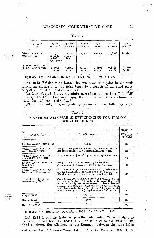
Ind 42.12 Rivet dimensions after driving. When the diameter of therivet holes in the longitudinal joints of a boiler or unfired pressure,,essel is not known, the diameter and cross-sectional area of rivets,after driving, shall be taken from the following tables:
'fable 1
Thicknessof Plate
%"0.25"
9/32"0.2812"
5/16"0.3125"
11/32"0.34375"
%"0.375"
%"0.375"
13/32"0.40625"
Diameter of 11/16" 11/16" %" %° %'< " 13/16" 13/16"Rivet after up, to &Driving includ- " Over
ing 2" '' 2" pitchpitch
Cross sectionalarea of rivetafter driving 0.3712 0.3712 0.4418 0.4418 0.4418 0.6186 0.5185
sq. in. sq. in. sq. in. sq. in. sq. in. sq. in. sq. in.
Boiler and Unfired Pressure Vessel Code Register, December, 1956. No. 12
WISCONSIN ADMINISTRATIVE CODE 13
Table 2
Thickness ofPlate
7/16"0.4375"
7/16"0.4375"
15/32"0.46875"
M"0.5"
9/16"0.5625"
%"0.625"
Diameter of Rivet %" 16/16" 15/16" 15/16" 1-1/1611 1-1/16"after Driving up to & over 2X"
including pitch2%"pitch
Cross sectional areaof rivet after driving 0.6013 0.6903 0.6903 0.6903 0.8866 0.8866
sq. in. sq. in. sq. in. sq. in. sq: in. sq. in.
History: Cr. Register, December, 1956, No. 12, eff. 1-1-57.
Ind 42.13 Efficiency of joint. The efficiency of a joint is the ratiowhich the strength of the joint bears to strength of the solid plate,and, shall be determined as follows:
(1) For jived joints, calculate according to sections Ind 44.50.andf Ind 41 5 of this co i using the values stated in sections Ind42. 0,' Ind 42 1 and Ind 42.12. 1'`
(2) For welded joints, calculate by reference to the following table:
Table 3MAXIMUM ALLOWABLE EFFICIENCIES FOR FUSION
WELDED JOINTS
MaximumJoint
Type of Joint Limitations EfficiencyPer .Cent
Double-Welded Butt Joint None 80
Single-Welded Butt Joint Longitudinal joints not over 1% inches thick. Nowith Backing Strip thickness limitations on circumferential joints. 80
Single-Welded Butt Joint Circumferential joints "only not over % inches thick.without Backing Strip 70
Double-Welded Full-Fillet Longitudinal joints not over . 1/9 inches thick.Lap Joint Circumferential joints not over % inches thick. 60
Single-Welded Full-Fillet Circumferential joints only not over % inches thickJoints with Plug Welds and for attachments of heads not over 24 inches out-
side diameter to shells not over % inches thick. - 50
Single-Full Fillet Joint For attachments to .heads convex to pressure to shellwithout Plug Welds not over % inches thick, only with use of fillet weld
on inside shell; for attachments to heads havingpressure on either side, with fillet weld on outside ofhead flange only, to shells not over 24 inches insidediameter and not over Y4 inches required thickness. 50
Forged Weld None 70 -
Brazed Steel None 80
Brazed Copper None 90
History: Cr. Register, December, 1956, No. 12, eff. 1-1-57.
Ind 42.14 Ligament between parallel tube holes. When a shell ordrum is drilled for tube holes in a line parallel to the axis of theshell or drum, the efficiency of the ligament between the tube holesBoiler and Unfired Pressure Vessel Code Register, December, 1956, No, 12

14 INDUSTRIAL COMMISSION
shall be determined as shown in sections Ind 41.50 and Ind 41.51 ofthis code,
History: Cr. Register, December, 1956, No. 12, eff. 1 -1-57.
Ind 42.15 Ligaments between diagonal tube holes. When a shell ordrum is drilled for tube holes in a line diagonal with the axis of theshell or drum, the efficiency of the ligaments bet.kge}r the to^ holesshall be determined as shown in sections Ind 41.50 and Ind 4:.51 ofthis code.
History: Cr. Register, December, 1956, No. 12, eff. 1-1-57.
Ind 42.16 Maximum pressure for cast iron boilers. (1) The maximumallowable working pressure on a steam boiler constructed wholly orprincipally of cast iron shall not exceed_ 15 pounds, per square inch.
(2) The maximum' allowable working pressure on boilers, the° tubes of which are secured to cast iron headers, shall not exceed 160pounds per square inch.
Historys Cr. Register, December, 1956, No. 12, eff. 1-1-57.
Ind 42.17 Safety or relief valves required. Every boiler or unfiredpressure vessel shall have one or more safety or relief valves set ator below the maximum allowable working pressure. On power boilersthe remaining valy s may be set at a higher pressure in accordancewith section Ind 42. 8.
History; Cr. Register, December, 1956, No. 12, eff. 1-1-57.
Ind 42.18 Safety valves for low pressure steam, miniature, andpower boilers. (1) Every boiler shall be provided with safety valvecapacity sufficient to discharge all the steam that can be generatedwithout an increase over the maximum allowable working pressureor to which the valve is set, except a 6% increase while the valveis discharging for power and miniature boilers, and a 5.pound persquare inch increase while the valve is discharging for low pressuresteam boilers.
(2) The steam generating capacity of a boiler in pounds of steamper hour may be determined by one of the following:
(a) Manufacturer's maximum output rating.
(b) Pounds of steam
Maximum Btu input per hour X 0.75per hour =
1000
(c) Actual evaporation test.
(d) On the basis of boiler heating surface or waterwall heatingsurface as given in the following table:
Boiler and Unfired Pressure Vessel Code Register, December, 1956. No. 12

A\T ISCONSIN'ADMINISTRATIVE CODE 15
Table 4MINIMUM POUNDS OF STEAM PER HOUR PER SQUARE
FOOT OF SURFACE
Type of Boiler Surface Firetube WatertubeBoilers Boilers
Power Boilers Boiler heating surfaceHand-fired------------------------------ 5 6Stoker-fired ----------------------------- 7 8Oil-, gas'-, or pulverized fuel-fired ---------- 8 10
Waterwall heating surfaceHand-fired------------------------------ 8 8Stoker-fired ----------------------------- 10 12Oil-, gas-, and pulverized fuel-fired ----- _--- 14 -; 16
Low Pressure Steam " Boiler heating surfaceand Miniature Any method of firing----------- --- 6 5:"Boilers
*Shall include cast iron boilers.
Note: Compliance with section Ind 42.18 -(1) vJ11 be required in every case.
(3) On power boilers one or more 'safety valves on the boiler propershall be set at or below the maximum allowable !working pressure.The remaining valves may be set within a range of 3 010 above themaximum allowable working pressure, but the range of setting of allof the valves on a boiler shall not exceed 10 010 of the highest pressureto which any valve is set.
(4) Safety valves ' which are constru ed I in accorq ne with thestandards as specified in sections Ind 41. O and Ind 41. 1 of this codeare acceptable. Safety valves constructed to other standards may beused if approved by the industrial commission. Dead-weight orweighted-lever safety valves shall not be used.
(5) When 2 or more safety valves are used on a boiler, they maybe mounted either separately or as twin valves made by placing indi-vidual valves on Y-bases, or duplex, triplex or multiplex valves havingtwo or more valves in the same body casing. The valves shall be madeof equal sizes, if possible, and
in any event if not of the same size,the smaller of the two valves shall have a relieving capacity of atleast 50% of that of the larger valve.
(6) The safety valve or valves shall be connected to the boilerindependent of any other steam connection, and attached as close aspractical to the boiler, without any unnecessary intervening pipe orfitting. Every safety valve shall be connected so as to stand in anupright position, with spindle vertical, when possible.
(7) The opening, or connection: between the boiler and the safetyvalve or valves shall have at least the area of the inlet of the valveor valves. No valve of any description shall-1 be placed between therequired safety valve or valves and the boiler, nor on the dischargepipe between the safety valve and the atmosphere. When a dischargepipe is used, the cross-sectional area shall be not less than the fullarea of the valve outlet or of the total of the areas of the valve out-lets discharging thereinto, and shall be as short and straight aspossible and so arranged to avoid , undue , stresses on the valve orvalves.
Boiler and Unfired Pressure Vessel Code Register, December, 1956. No. 1.2
16 INDUSTRIAL COMMISSION
(a) All safety-valve discharges shall be so located or piped as to becarried :clear from -running; boards, platforms, or otherwise carriedto a safe location.
(b) Provision for gravity drain shall be made in the dischargepipe, at or near each safety valve, and where water of condensationmay collect.
(8) (a) The spring in a safety valve in service for pressures up toand including 250 pounds shall not be used for any pressure morethan 10% above or 10% below that for -which it was designed.For higher pressures, the spring shall not be used for any pressuremore than 5 010 above or 5% below that for which it was designed.
(b) If the operating conditions of a valve are changed so as torequire a new spring for a different pressure, the valve shall be ad-justed by the manufacturer or his authorized representative who shallfurnish and install a new name plate.
(9) Every superheater shall have one or more safety valves nearthe outlet. The discharge capacity of the safety valve or ,valves on anattached superheater may be included in determining the number andsize of the safety valves for the boiler, provided there are no inter-vening valves between the superheater safety valve and the boiler, andprovided the discharge capacity of the safety valve or valves on theboiler, as distinct from the superheater, is at least 75% of theaggregate valve capacity: required. A soot-blower connection may beattached to the same outlet from the superheater that is used for thesafety valve connection.
(10) ;(a) Every boiler shall have outlet connections for the re-quired safety valve or valves, independent of any other outside steamconnection. The area of the boiler <opening or -openings shall be , atleast equal to the aggregate areas of inlet connections of all of thesafety valves to _ be attached thereto. An internal collecting pipe,splash plate, or pan be used, provided the _total area for inletof steam thereto is not _less than twice the aggregate areas of theinlet connections of the attached safety valves. The holes insuchcollection pipes shall be at least 1/4 inch in diameter and the leastdimension in any other form of opening for <inlet of steam shall be1/4 inch.- (b) If safety valves are attached to a „separate steam drum or
dome, the opening between the boiler proper and the steam drumrdome shall be not less than required by section Ind 42.18—(10)—(h).
(c) When boilers allowed different pressures are connected to acommon steam main and all safety valves are not set at the lowestpressure allowed, no safety valve shall be set to exceed by more than50% the lowest pressure allowed.
(d) For conditions exceeding those specified in the above para-graph, the case shall be referred to the industrial commission fordecision.
History: Cr. Regist er, December, 1956, No. 12, eff. 1-1-57.
Ind 42.19 Water-relief valves for hot water boilers. (1) Each hotwater boiler shallhave one or more relief valves of the spring loadedtype, without disc 'guides on the pressure 'side of the 'valve. Thevalves shall be set to relieve at a pressure at or below the maximumallowable working pressure of the boiler.
Boiler and Unfired Pressure Vessel Code Register, December, 1956. No. 12
WISCONSIN ADMINISTRATIVE CODE 17
(2) ReliefInd
which f are constructed in accordance with sec-tions Ind 41. O and Ind 41.51 i°of this code are acceptable. Relief valvesconstructed to other standards may be used if approved by the indus-trial commission.
(3) Water-relief valves shall be attached directly or as close aspossible to the boiler without any unnecessary intervening pipe orfitting. A water-relief valve shall not be connected to an internal pipein the boiler. Water-relief valves shall be connected so as to stand up-right with the spindle vertical when possible.
(4) No shut-off of any description shall be placed between thewater-relief valve and the boiler, nor on discharge pipes betweensuch valve and the atmosphere.
(5) When a discharge pipe is used its area shall be not less thanthe area of the valve or aggregate area based on the nominal diame-ters of the valves with which it connects. The discharge pipe shall bepitched away from the valve to prevent water from lodging in theupper part of the valve or in the pipe. The water-relief valve shallbe so located and piped that there will be no clanger of scaldingattendants.
(6) The required water-relief valve capacity for any hot waterboiler shall be equal to the maximum Btu output at the boiler nozzleor shall be equal to the boiler heating surface multiplied by 5000.
(7) The water-relief valve capacity for each hot water boiler shallbe such that the valve or valves will relieve all the pressure that canbe generated by the boiler without allowing the pressure to rise morethan 3 pounds above the maximum allowable working pressure of theboiler.
(8) Every boiler shall have proper outlet connections for the re-quired water-relief valves, independent of any other connection out-side the 'boiler. The area of the opening or openings shall be at leastequal to the aggregate area based on the nominal diameters of all ofthe water-relief valves with which it connects.
(9) When a hot water supply is heated indirectly by steam in acoil or 'pipe, the pressure of the steam used .shall not exceed the safeworking pressure of the hot water tank, and a water-relief valveof at least one inch in diameter, set to relieve at or below the maxi-mum allowable working pressure of the tank, shall be used.
History: Cr. Register, December, 1956, No. 12, eff, 1-1-57.
Ind 42.20 "Thermometers for hot water boilers. Every hot-waterboiler shall have a thermometer so located and connected that it shallbe easily readable when observing the water pressure or altitude. Thethermometer shall be so located that it shall at all times 'indicatethe temperature in degrees Fahrenheit of the water in the boiler, ator near the outlet.
History: Cr. Register, December, 1956, No, 12, eff. 1-1-57.
Ind 42.21 Water glass. Every low pressure ,steam, miniature andpower boiler shall have at least one <water glass, equipped with avalved drain, the lowest visible part of ;which shall be at or abovethe following location except that in all cases it shall be so placed asto give adequate protection to those parts of a boiler proper subjectto the heat of the products of combustion.
$giler and Ullfired Pressure Vessel Cocle Register, December, 1956. No. 1.
18 INDUSTRIAL COMMISSION
(1) 'HORIZONTAL RETURN TUBULAR BOILERS—nOt less than 4 inchesabove the upper -surface of the upper row of tubes except when thedistance between the uppermost surface of the tubes and the top ofsteam space is 13 inches or less the distance may be reduced to 2inches.
(2) LOCOMOTIVE .TYPE BOILERS-3 inches above the highest part, ofthe crown sheet.
(3) VERTICAL TIRE TUBE BOILERS—not less than one-third the lengthof the tube above the lower tube sheets.
(4) WATER TUBE BoILERs—as specified by the manufacturer.(5) SCOTCH MARINE TYPE BOILERS-3 inches above the combustion
chamber top.
Note: For Dry Back see section Ind 42.21 (1)
(6) CAST IRON ,BOILERs—as specified by the manufacturer.(7) OTHER TYPES AND DESIGNs—for other types and new designs
the location shall be fixed by the manufacturer subject to approvalby the industrial commission.
History: Cr. Register, December, 1956, No. 12, eff. 1-1-57.
Ind 42.22 Gage cocks. (1) Every steam boiler, except those exemptedbelow, shall >3 gage cocks located within the range of the visibleportion of the water glass.
(2) The following boilers shall not be required to have gage cocks:(a) Boilers which do, not have a definite water level.(b) Boilers which have 2 water glasses spaced not less than 2 feet
apart on the same horizontal line.(c) Boilers which have 2 remote water level indicators in addition
to the required water glass.(d) Miniature boilers.(3) The following boilers shall be _required to have only ,2 gage
cocks:(a) Low pressure steam boilers.(b) Locomotive type boilers not over 36 inches in diameter.(c) Firebox or water, leg, boilers in which the water heating sur-
face does not exceed 50 square feet.History: Cr. Register, December, 1956, No. 12, efL. 1-1-57.
Ind 42.23 Water column piping. (1) No connections shall be placedon pipes connecting the 'water column to the boiler except connectionsfor damper regulator, ,feed water regulator, steam gage or drains.
(2) The minimum size of the pipes connecting the water columnto a boiler shall be 1 inch. Water-glass fittings or gage cocks may beconnected direct to the boiler.
(3) The water connections to the water column of a boiler, whenpracticable, shall be provided with a cross at each right-angle turn tofacilitate cleaning. The water column shall be fitted with a drain cockor drain valve with a suitable connection to the ashpit or other safepoint of waste, and if the water connection thereto has a rising bendor pocket which cannot be drained by means of the water columndrain, an additional drain shall be :placed in this connection in orderthat it may be blown off to clear any sediment from the pipe.
(4) The steam connection to the water column of =a horizontal-return tubular boiler shall be taken from the top of the shell or the
Boiler and Unfired Pressure Vessel Code Register. December, 1956. No. 12

WISCONSIN ADMINISTRATIVE CODE 19
upper part of the head; the water connection shall be taken from thefront head at a point not less than 6 inches below the center line ofthe shell. For the firebox types of boilers, the water connection to thewater 'column shall be taken at a point not less than 6 inches belowthe lowest water 'line or as near thereto as possible, and in no caseless than 18 inches above the mud ring.
(5) When shut-offs are used on the connections to a water column,they shall be either outside-screw-and-yoke type valves or stop cockswith levers permanently fastened thereto and marked in line withtheir passage. Where stop cocks are used they shall be of a type withthe plug held in place by a guard or gland.
History: Cr. Register, December, 1956, No. 12, eff. 1-1-57.
Ind 42.24 Pressure gages. (1) (a) Every unfired pressure vesselor boiler shall be provided with a pressure gage connected to theupper part of the vessel and so arranged that the gage cannot beshut off from the vessel except that a shut-off valve or cock shallbe placed close to the gage to permit removal for testing while thepressure vessel is in operation.
(b) For steam boilers the gage may also be connected to thewater column or water column steam connection. For steam boilersa siphon or equivalent device of sufficient capacity to keep the gagetube filled with water shall be provided.
(2) The dial of the pressure gage _shall be graduated to at leastone and one-half times the pressure at which the safety or reliefvalve is set except as follows:
(a) On low pressure steam boilers the gage shall be graduated toat least 30 pounds per square inch.
(b) On hot water boilers the pressure or altitude gage shall begraduated to at least one and one-half times the maximum allowableworking pressure.
(3) (a) For low pressure steam boilers the travel of the pointerfrom zero to 30 pounds per square inch shall be at least 4 inches.
(b) Effective stops shall be provided for the indicating 'pointer atthe lowest and highest pressure points.
(4) The pressure gage dial shall at all times be protected by 'atransparent cover and shall be kept clear at all times. This gageshould be so located as to be readily visible to the operator.
History: Cr. Register, December, 1956, No. 12, eff. 1-1-57.
Ind 42.25 Stop valves on pressure discharge outlets. (1) Each:pres-sure discharge outlet on unfired pressure vessels, miniature and powerboilers, except safety or relief valve outlets, shall be fitted with oneor more stop valves, located as near to the pressure vessel as prac-ticable. When 2 or more low pressure steam boilers are connectedto a common' header,' a stop valve shall be provided in the steam out-let of each boiler as near to the boiler as practicable.
(2) When 2 stop valves are placed in the steam connection betweena power boiler and the steam main there shall be a free blow drainbetween them. The discharge of this drain valve shall be visible to theoperator while manipulating the valve.
(3) (a) When <a stop valve is so located that water can accumu-late, drains shall be provided.
Boiler and Unfired, Pressure Vessel Code Register, December, 1956. No. 12
20 INDUSTRIAL. COMMISSION
(b) Each dry pipe or similar apparatus shall have two holesdrilled into it. These holes shall be not less than 1/2 inch diametereach and shall be kept open so that the condensation can escape.
(4) Each superheater shall be equipped with at least one drain solocated as will most effectively provide for the proper operation of theapparatus.
History: Cr, Register, December, 1956, No. 12, efi'. 1-1-57.
Ind 42.26 Steam mains. Provision shall be made for the expansionand contraction of steam mains connected to boilers, by providingsubstantial anchorage at suitable points, so that there shall be noundue strain transmitted to the boiler. Steam reservoirs shall beused on steam mains when heavy pulsations of the steam currentscause vibration of the boiler shell plates.
History,: Cr. Register, December, 1956, No. 12, eft. 1-1-57.
Ind 42.27 Bottom blow -off or drain. (1) Connected to the lowestspace practicable of each pressure vessel, there shall be a bottom blow-off pipe fitted with a valve or cock. The valves shall be of straight-way or angle construction and cocks shall have the plugs held inplace with a gland or guard. Straightway globe valves of the ordinarytype or 'valves of such type that dams or pockets can exist for thecollection of sediment, shall not be used on such connections.
(2) A surface blow-off shall not exceed 2 1/2 inch pipe size andthe internal and external pipes, when used, shall form a continuouspassage, but with clearance between their ends and arranged so thatthe removal of either will not disturb the other. A properly designedsteel bushing or a flanged connection shall be used.
(3) (a) Each boiler shall have a bottom blow-off pipe, fitted witha valve or _cock, in direct connection with the lowest water spacepracticable. The maximum size of pipe and fittings shall be 2 1/2 !inchesand the minimum size shall be one inch except that for boilers with100 square feet of water heating surface or Tess and low pressuresteam boilers the minimum size of pipe and fittings may be 3/4 inch.Straightway, globe valves of the ordinary type or valves of such ,typethat dams or pockets can exist for the collection of sediment, shallnot be used on such connections.
(b) The bottom blow-off pipe for low pressure steam, miniature,and hot water boilers may be connected to return connections whichare the same_ size or larger than the size herein specified. -In suchcase, the blow-off shall be so located that the connection may be com-pletely drained.
(4) A'bottom blow-off cock shall have the plug held in place by aguard or gland. The end of the plug _shall be distinctly marked inline with the passage.
(5) (a) For power boilers, the bottom blow-off pipe or pipes shallbe of wrought iron or steel and shall be at least extra heavy.
(b) The fittings between .a power boiler and the required bottomblow-off valve or valves shall be of steel, cast steel or malleable ironand shall be not less than extra heavy ;construction for pressures notexceeding 150 pounds per square inch.
(c) For pressures exceeding 150 pounds per square inch such fit-tings_shall be of steel construction and not less than extra heavy.
Boiler and Unfired Pressure Vessel Code Register, December, 1956, No. 12
WISCONSIN ADMINISTRATIVE CODE 21
(d) Cast iron pipe and fittings shall not be used in the bottom blow-off pipe between the boiler and the bottom blow-off valve or valves.
(6) (a) On all boilers except those used for traction and portablepurposes, when the maximum allowable working pressure exceeds125 pounds per square inch, each bottom blow-off pipe shall have 2slow-opening valves, or one slow-opening valve and a cock, and suchvalves, or valve and cock, shall be at least extra heavy construction.On a boiler having multiple blow-off pipes, a single master valve maybe placed on the common blow-off pipe from the boiler, in which caseonly one valve on each individual blow-off is required. Two independ-ent valves, or a valve and a cock may be combined in one body pro-vided the combined fitting is the equivalent of 2 independent valves,
or a valve and a cock, so that the failure of one to operate could notaffect the operation of the other.
(b) Every traction and portable boiler shall have a bottom blow-offvalve; when the maximum allowable working pressure exceeds 125pounds per square inch, the blow-off valve shall. be at least extraheavy.
(c) For pressures exceeding 200 pounds per square inch the valvesor cocks shall be of steel construction.
(d) The blow-off valve or valves shall be the full size of the blow-off pipe.
(7) A bottom blow-off pipe when exposed to direct furnace heatshall be protected by fire brick or other heat resisting material soarranged that the pipe may be inspected.
(8) An opening in the boiler setting for a blow-off pipe shall bearranged to provide for ^ee expansion and contraction.
(9) See section Ind 41:11 for required boiler blow-off equipment.History: Cr. Register, December, 1956, No. 12, eff. 1-1-57.
Ind 42.28 Feed pipe. (1) (a) Each low pressure steam, miniatureand power 'boiler shall have the feed pipe fitted with a check valvenear the boiler and a stop valve between the check valve and theboiler. Single low pressure steam boiler installations of the gravityreturn type which do not have a stop valve in the steam outlet linewill not be required to have 'a stop valve in the return pipe.
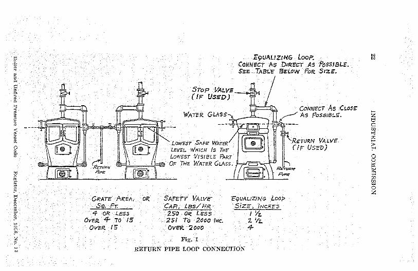
(b) On low pressure steam boilers, the return pipe loop connectionshown in Fig. 1 may be used in place of the check valve.
(2) (a), The feed water shall be introduced into a boiler in sucha manner that the water will not be discharged directly againstsurfaces exposed to gases of high temperature, or to direct radiationfrom the fire, or close to riveted ,joints of shell or furnace sheets.
-(b) Where horizontal return tubular boilers are fed through thefront a boiler bushing or its equivalent shall be used and the feedwater shall discharge at about three- fifths the length of the boilerfrom the front head, and above the second row of tubes from the top.
- (3) When 2 or more power boilers are fed from a common source,there shall be a globe or regulating valve on the branch to eachboiler, between the check valve and the source of supply. When 2 ormore low pressure steam boilers, using a gravity return system arefed from a common source, one check valve may be placed on themain return pipe with a stop valve on the branch return to each boiler.Wherever glove valves are used on feed piping, the inlet shall beunder the disc of the valve.
Boiler and Unfired Pressure Vessel Code Register, December, 1966, No. 12
t0
ro
m
0
N
C°o
z0
E9URLIZING , Loon. pCONNECT AS D►REGT AS I bSSIB L.E.SEE-..TABLE SELow FoR Size.
51-OP VALYF(IF USED)
CoNivecr As CLOSEWATEIZ GLASS-, ^^ AS PoSsiat-5.
a'
LOWEST SAFE (MATER11 ea If '^-IZETURN VALVF.
LEVEL WHICH Is THE IF USED)
LOWEST VISIBLE tPAP.T
f7FruR.a o o '' of THE WATER GLASS.
I lL=J^ JL°. P6P2'
GRATE AREA, OR SAFETY VALVE--EQUALIZlNr, 'Loop
S(q, Fr CAP, LSslsp- SiZE, INCHES4 OR ;LE55 - 250 OR LESS I YZ
OVER $ To 15 251 To 2000 INc 2 `/zOVER 15 Ovex 2000
Fig. 1
RETURN PIPE LOOP CONNECTION
zd
H
r
c^O
Oz
WISCONSIN ADMINISTRATIVE CODE 23
(4) (a) Means shall be provided for feeding a boiler against themaximum allowable working pressure or the pressure at which thesafety valve is set to blow.
(b) -Where a source of feed is available at a sufficient pressure tofeed the boiler against a pressure 6^o higher than that at which thesafety valve is set to blow, this may be considered one of the means.
(5) Every boiler and its piping system shall be provided with awater supply line from an outside source of water supply in orderto'' replace ' 'the 'water leaving the system through leakage, processwork, or other reasons.
(a) A stop and check valve shall be provided in the water supplyline with the stop valve closest to the boiler.
(b) On low pressure steam and hot water boilers, the water supplyline shall be connected to the boiler return or feed piping system andnot directly to the boiler.
(c) On low pressure steam, miniature, and hot water boilers, thewater supply line pressure shall be high enough to feed the boiler orthe system against the maximum allowable working pressure of theboiler.
(6) A heater for oil or other liquid harmful to boiler operationshall not be installed directly in the steam or water space within aboiler. Where an external type heater for such service is used, posi-tive means shall be provided to prevent the introduction into the boilerof oil or other liquid harmful to boiler. operation.
History: Cr. Register, December, 1956, No. 12, eff. 1-1-57.
Ind 42.29 Combustion regulators for boilers. '(1) A temperaturecombustion regulator, which will control the rate of combustion toprevent the temperature of the water from rising above 250 Fahren-heit at or near the outlet, or a thermostatic device which will relievethe pressure on the boiler when the temperature exceeds 250° Fahren-heit, shall be used on all hot water boilers.
(2) When a pressure combustion regulator is used on a steamboiler, it shall operate to prevent the steam pressure from risingabove the maximum allowable working pressure for the boiler.
History: Cr. Register, December, 3956, No. 12, eff. 1-1-157.
Ind 42.30 Flanged connections. Openings in boilers having flangedconnections shall have the flanges conform to the American standardfor the corresponding drilling for bolts or studs. Steel outlet nozzlesand flanges may be riveted or welded to the shell. Cast iron outletnozzles or flanges will be permitted only on low pressure steam or hotwater boilers and can be attached to the shell only by riveting.
History: Cr. Register, December, 1956, No. 12, eff, 1-1-57.
Ind 42.31 Washout and inspection openings. (1) All boilers or un-fired pressure vessels shall be provided with suitable 'manhole orhandhole openings, except 'special types where they are manifestlynot needed or used.
(2) All horizontal fire tube boilers shall be required to have thefollowing manhole or handhole openings: (a) A manhole in the fronthead below the tubes for: 1. Horizontal return tubular power boilersover 54 inches in diameter.
2. Horizontal return tubular low pressure steam or hot waterboilers over 60 inches in diameter.
Boiler and Unfired Pressure Vessel Code Register, December, 1956. No. 12

04 INDUSTRIAL COMMISSION
3. For smaller boilers a handhole may be used in place of themanhole.
(b) A manhole in the upper part of the shell or head for: 1. Hori-zontal return tubular, fire box and locomotive power boilers over 48inches.
2. Scotch marine power boilers over 54 inches in diameter.
3. Low pressure steam boilers over 60 inches in diameter.
4. For smaller boilers a handhole may be used in place of themanhole.
(c) Locomotive and fire box boilers shall also have the followinghandhole or washout openings: 1. One at each of the four corners ofthe lower portion of the water leg.
2. One in the front head at or about the line of the crown sheet.3. One near the throat sheet of power boilers where possible.4. One in the rear head of power boilers below the tubes.(3) '(a) A vertical fire tube boiler, except boilers 24 inches or less
in `diameter, shall have not less than 4 handholes located as fol-lows: Two in the shell at or about the line of the crown sheet or lowertube sheet; 2 in the shell at the lower part of the water leg.
(b) Vertical fire tube boilers 24 inches or less in diameter shallhave three one inch diameter washout plugs except that boilers notexceeding 12 inches internal diameter . `having less than _ 10 squarefeet of water heating surface need not have more than 2 such wash-out Mugs, one of which may be used for the attachment of thebottom blow-off valve. The threads of the washout plugs shall be ofaon-ferrous material.
(4) All unfired pressure vessels, in other than non-corrosive service,1.8 inches in -diameter or over shall be provided with one of thefollowing washout or inspection opening ,combinations: 2 hand-holes in the shell or heads, a manhole, or 2 or more plugged threadedopenings of ,2 inches in .diameter.
(5) All ,unfired pressure vessels, in other than non-corrosive serv-ice, less than 18" and over 12"- in diameter <must be provided with atleast -2 handholes, or 2 inspection holes, properly located for in-spection, the inspection holes to be not less than 1 1/z" pipe size, unlessthe pressure vessel has a removable head or cover plate. For vessels12" and under inspection openings may be omitted.
(a) Vessels not over 16" in inside diameter that are installed sothat they must be disconnected from an assembly to permit inspection,heed not be provided with openings for inspection only, if there areat least two removable pipe' connections not less than 1 1/2" pipe size.
(6) Where handholes are provided, such handholes shall not be lessthan 2 1/2 inches by 3% inches in size.
(7) Washout plugs, except for vertical fire tube boilers, shall be notless than 1 1/2 inch pipe size and shall have threads of non-ferrousmaterials.
(8) Every cast iron boiler shall be provided_ with washout openingsto permit the removal of any sediment that may accumulate therein.Washout openings may be used for return ,pipe connection if thewashout plug is placed in a tee so that the plug is directly oppositeand as close as possible to the opening in the boiler.
History: Cr. Register, December, 1956, No. 12, eff. 1-1-57.
P,oller and. Unflred Pressure Vessel Code Register, December, 1956. No. 12
WISCONSIN ADMINISTRATIVh CODE 25
Ind 42.32 Manholes. Where manholes are provided, such manholesshall be not less than 11 inches by 15 inches, or 10 inches by 16inches in size. <A circular manhole opening shall be not less than 15inches in diameter. Any opening, the greatest dimension of whichexceeds 6 inches, in the shell of an unfired pressure vessel shall bereinforced in accordance with rules for manholes. No manholes orhandholes are required on unfired pressure vessels which have remova-ble heads or cover plates.
History: Cr. Register, December, 1956, No. 12, eff. 1-1-57.
Ind 42.33 Maintenance. (1) All boilers or unfired pressure vesselsshall be installed and maintained in such a manner as to preventexcessive corrosion or deterioration.
(2) The inspector shall note conditions during the internal inspec-tion, external inspection or hydrostatic pressure test and order suchchanges or repairs as will place the pressure vessel in a safe workingcondition.
History: Cr. Register, December, 1956, No. 12, eff. 1-1-57.
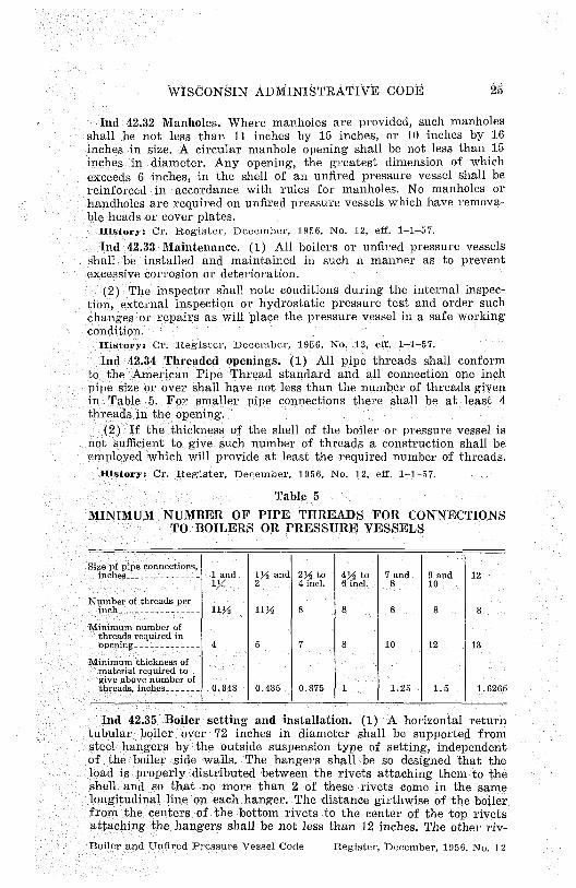
Ind 42.34 Threaded openings. (1) All pipe threads shall conformto the American Pipe Thread standard and all connection one inchpipe size or over shall have not less than the number of threads givenin Table 5. For smaller, pipe connections there shall be at least 4threads in the opening.
(2) If the thickness of the shell of the boiler or pressure vessel isnot sufficient to .give such number of threads a. construction shall beemployed which will provide at least the required number of threads.
History: Cr. Register, December, 1956, No. 12, ,eff. 1-1-57.
Table 5
MINIMUM NUMBER OF PIPE THREADS FOR CONNECTIONSTO BOILERS OR PRESSURE VESSELS
Size pf pipe connections,inches--------------- :1 and
1%
Number of threads perinch---------------- 11Y
Minimum number ofthreads required inopening------------- 45 7 8 10 12 13
Minimum thickness ofmaterial required togive above number ofthreads,inebes------- 0.348 0.435 0.875 1 1.25 - 1.5 1.6265
Ind 42.35 Boiler setting and installation. (1) 'A horizontal returntubular boiler over 72 inches in diameter shall be 'supported fromsteel hangers by the outside suspension type of setting, independentof the boiler- side walls. The hangers shall be so designed that theload is properly distributed between the rivets attaching them to theshell and so that no more than 2 of these 'rivets 'come in the samelongitudinal line on each hanger. The distance girthwise of the boilerfrom the centers of the bottom rivets to the center of the top rivetsattaching the hangers shall be not less than 12 inches. The other riv-
1Y2 and 2Y2 to 4% to 7 and 9 and 122 4 Incl. 6 incl. 8 10
11Y 8 s s 8 8
Boiler and Unfired Pressure Vessel Code Register, December, 1956. No. 12
23 INDUSTRIAL COMMISSION
ets used sha`1 be spaced evenly between these points, If more than4 hangers are used they shall be set in 4 pairs.
(2)'A horizontal return tubular boiler over 54 inches and up toand including 72 inches in diameter, shall be supported by the outsidesuspension type of setting, or at 4 points by not less than 8 steel orcast iron 'brackets, set in pairs. A horizontal return tubular boiler upto and including 54 inches in diameter shall be supported by the out-side suspens i on type of setting, or by not less than 2 steel or cast ironbrackets on each side.
(3) Lugs or hangers, when used to support a boiler of any typeshall be properly fitted to the surfaces to which they are attached.If riveted the shearing , nd ,crushing stresses on the rivets used forattaching , the lugs orangArs shall not exceed 8 % of the strengthgiven in section Ind 42. 1. here it is impractical to use rivets, studswith not less than 10 threads per inch may be used. In computingthe shearingf stress, the area at the bottom of the thread shall beused. Strert h ,wvelding r^r y 1 e used, if done in accordance with sec-tions Ind 41. 01and Ind 41.51 `6f this code.
(4) Wet bottom stationary boilers shall have a space of not lessthan 12 inches between the bottom of the boiler and the floor line,with access for inspection.
(5) The upper surface of the fire grate of an internally fired boilerof the open bottom locomotive, vertical fire tube or similar type, shallnot be below the water space in the water leg, except where the rivetsat the bottom of the water leg are '`protected from the action of thefire and products of combustion.
'History: Cr. Register, December, 1956, No. 12, eff. 1-1-57.
Ind 42.36 Access and firing doors. The minimum size of an accessdoor to be placed in a boiler setting: shall be 12 inches by 16 inchesor equivalent area, 11 inches to be the least; dimension in any case.
History: Cr. Register, December, 1956, No. 12, eff. 1-1-57.
Ind 42.37 Water tube boiler doors. A water tube boiler shall havethe firing doors, furnace inspection doors and clinker doors of theinward opening type, unless such doors are provided with latching orfastening devices or otherwise so , constructed as to prevent them,when closed, from being blown open by pressure on the furnace side.
History: Cr. Register, December, 1956, No, 12, eff. 1-1-57.
Ind 42.38 Low-water cut-off and water feeder. (1) Every low pres-sure steam or power boiler which is automatically ; fired shall beequipped with an automatic low-water fuel cut-off or other devicewhich will perform a similar function, `so located as to automaticallycut off the fuel supply when the 'surface of the water falls to thelowest safe water line. if a water feeding device is installed, it shallbe so constructed that the water inlet valve cannot feed water intothe boiler through the float chamber: and < so located as to supplyrequisite feed water. The lowest safe water line shall be not lowerthan the lowest visible part of the water glass.
(2) Such a fuel or feed water, control device may be attacheddirect to a boiler or to the tapped openings provided for attaching awater glass direct to a boiler, p rovided that such connections from theboiler are non-ferrous tees or Y's not less than 1/2 inch pipe ' size ' be-
Boiler and Un fired Pressure Vessel Code Register, December, 1956. No. 12

WISCONSIN ADMINISTRATIVE CODE 27
tween the boiler and the water glass so that the water glass is at-tached direct and as close as possible to the boiler; the straightwaytapping of the Y or tee to take the water glass fittings, the sideoutlet of the Y or tee to take the fuel cut-off or water-feeding device.The ends of all nipples shall be reamed to full size diameter.
(3) Designs embodying a float and float bowl shall have a verticalstraightway valved drain pipe at the lowest point in the water equal-izing pipe connections by which the bowl and the equalizing pipe canbe flushed and the device tested.
History: Cr. Register, December, 1956, No. 12, eff. 1-1-57.
Ind 42.39 Safety valves, relief valves and connections for unfiredpressure vessels. (1) Safety valves which ar constructed }n accord-ance with the standards of sections Ind 41`004nd Ind 41511of thiscode are acceptable. Safety valves constructed to other standards maybe used if approved by the industrial commission.
(2) Each safety or relief valve shall have a full size direct con-nection to the pressure vessel. When an escape pipe is used it shallbe full sized and fitted with an open drain, to prevent water lodgingin the tipper part of the safety or relief valve or escape pipe. Whena pressure vessel is fitted with 2 safety or relief valves on one con-nection, this connection to the pressure vessel shall have a cross-sectional area equal to or greater than the combined area of the 2safety or relief valves. No valve of any description shall be placedbetween the safety or relief valve and the pressure vessel, nor on theescape pipe between the safety or relief valve and the atmosphere.
(3) When an elbow is placed on a safety or relief valve escape pipeit shall be located close to the safety or relief valve outlet, or theescape pipe shall be securely anchored and supported.
History: ; Cr. Register, December, 1956, No. 12, eff. 1-1-57.
Ind 42.40 Pressure relief devices on unfired pressure vessels. (1)VESSELS rOR CONTAINING GASES. When the capacity of the safetyvalve on an existing tank for containing gases is not known, the re-lieving capacity of such safety valve shall be determined from Table 6.Such safety valves shall not exceed 4 inches in diameter.
(2) VESSELS SUPPLIED THROUGH PRESSURE REDUCING VALVES. Thefollowing formula shall be used for determining the sizes of safetyand relief valves on unfired pressure vessels such as pressure cookers,indirect hot water heaters, equipment in heating systems, etc., whichare supplied through pressure reducing valves from boilers carryinga higher steam pressure:
RVC = 1/3 X OC X VSPAwhere RVC relief valve capacity, lbs. of steam per hour.
OC orifice capacity, lbs. of steam per hour per square hicn(See Table 7)
VSPA ^ valve size pipe area, sq. in. (See Table 8)Note: Most pressure reducing valves are arranged with a valved by-pass
which also acts as a potential steam source hazard in case the by-pass isleft open. Where such valved by-pass is used, the following formula shallbe used to determine the steam flow rate through the by-pass:
RVC._ 1/2 X OC X BPAwhere RVC =: relief valve capacity, lbs. of steam per 'hour..
OC =orifice capacity, lbs. of steam per hour per square inch.(See 'Table 7)
BPA = by-pass pipe area, sq. inch. (See Table 8)
Boiler and Unfired Pressure Vessel Code Register, December, 1956, No, t12

t^0
Table 6a
MAXIMUM FREE AIR SUPPLIED IN CUBIC FEET PER MINUTE FOR DIFFERENT SIZES OF SAFETYVALVES AT 'STATED PRESSURES
yi Gage pressure, poundsDiameter of Valve (inches)
50 100 150 - 200 250 300 350 400
— - - - -- - - - " - -- - - --- -------- ----- --- --------- ----- 53__ _-___ -____ __ ___ __ 20 32 42 51
8§59 67 74 111
m%_- ____ -____ ____ _-___ ___ _ 37 59 78 96 112 127 141 1761 _
--------------------------------------------------58 94 124 152 178 202 224 248
1X/---- — ------------- ----- --- ---- ------------ 84 135 180 221 259 293 325 ----------
n 1Y2--------- ------------------------------------- — 114 186 248 302 354 400 444 ----------2 _ 189 306 410 501 592 668 741m2Y2_ __ ____ _ ____ _____ _____ ________ 282 457 613 750 880 998 1114 __ ___
3------=-------`------------------------------------ 393 638 856 _ '1050 1230 1398 1557 ----------
Gage Pressure, poundsDiameter of Valve (inches)
500 600 800 1,000 1,200 1,600 2,000—
2,400mm—
tj %_ __-_ ____ ___- -___ __ - - - - 61 70 84 97 109 128 147 167
3------------------------------------------------- 129 147 177 205 230 270 304 330_- - _____ ___ _---_ _____ __ ______ 224 232 242 346 386 423 474 518
1-`------------------------------------------------- 286 324 390 450 500 586 ---------- ----------1 Y4 -------------------------------------------------- 374 ---------- 5091'2-------------------------------------------------- 472 ---------- 634 ---------- ---------- ---------- ---------- ------------------------------------------------------------- - --- - - --- --- --- -- ---- - - --- - --------------------------------------------------
3-- - !--_-- -_ -- -- -- -- ---- - - -- - -
M00
zc
aC
O
Oz
r
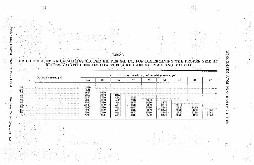
Table 7'd W.
n6 ORIFICE RELIEVING CAPACITIES, LB. PER HR. PER SQ. IN., FOR DETERMINING THE PROPER SIZE OFZ RELIEF VALVES USED ON LOW PRESSURE SIDE OF REDUCING VALVES
Pressure-reducing valve inlet pressure, psiOutlet Pressure, psi y —
125 100 85 75 60, 50 40 so 25
0—110--------------------------------------- 4550 ----- --- -- ---------- ---------- ---------- ------ --- - ---------- ---------- ----------100------=--85-_
-------- 56306640
----------4070
---------- ---------- ---------- ---------- ---------- ---------- ----------
75-i -------------------------------------_______
7050 4980----------
3150----------- -------- -
--------------------
--------------------
- -------------------
-- ------- -----------
-------- ---
----------60__50---------------------------------------
____ -:___ ____ ______ 72007200
57505920
45405000
35204230
----------2680
---- -- -- ------------- ------------ -------- -------------------- -
40;-_ -_<______________________________ 7200 5920 5140 4630 3480 2470 ---------- ---------- ----------30-- _ __ ------------------- 7200 5920 5140 4630 3860 3140 2210 ---------- ---------- C15__25 - - ------------------------------------- 7200
720059205920
5140 46304630
38603860
3340 2580 1485---
t:f 10-_-------------------------------------
__--______________ 7200 592051405140 4630 3860
33403340
28302830
23202320 2060
5-- -____ ______________________ 7200 5920 5140 4630 3860 3340 2830 2320 2060
Lt
O
30 INDUSTRIAL COMMISSION
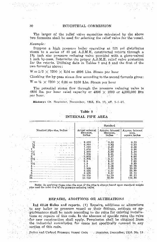
The larger of the relief valve capacities calculated by the abovetwo formulas shall be used for selecting the relief valve for the vessel.
Example:Suppose a high pressure boiler operating at 125 psi distributes
steam to a series of 40 psi A.S.M.E. constructed retorts through a1% inch size pressure reducing valve provided with a glove-valved1 inch by-pass. Determine the proper A.S.M.E. relief valve protectionfor the retorts. Utilizing data in Tables 7 and 8 and the first of thetwo formulas above:
W = 1/3 X 7200 X 2.04 4896 Lbs. Steam per hour
Checking the by-pass steam flow according to the second formula gives:
W % X 7200 X 0.86= 3100 Lbs. Steam per hour
The potential steam flow through the pressure reducing valve is4896 lbs. per hour rated capacity or 4896.X;1000 or 4,896,000 Btuper hour.
History: Cr. Register, December, 1956, No. 12, eff. 1-1-57.
Table 8
INTERNAL PIPE AREA
Standard
Nominal pipe size, inches Actual external Approx. internal Approx. internal
diameter, diameter, area,
inches inches - squareinches
Y8-__ ------------- 0.675 0.49 0.19---- --------- 0.840 0.62 0.30
Y4----------------------------1.050 0.82 0.53
1------------------------------ 1.315 1.05 0.86
1X --------------------------- 1.660 1.38 1.50
1Y2 -------------------- ------- 1.900 1.61 2.04
2_----------------------------- 2.375 2.07 3.36
2M -- --- - ------ 2.875 2.47 4.78
3 ------------------------------ 3.5 3.07 7.39
3 Y2 ---------------------------- 4.0 3.55 9.89
4 ------------------------------ 4.5 4:03 12.73
5------------------------------ 5.563 5.05 19.99
6------------------------------ 6.625 6.07 28.89
8 ------------------------------ 8.625 8.07 51.15
10______________________________ 10.750 10.19 81.55
12 ______________________________ 12.750 12.09 114.80
Note: In applying these rules the area of the pipe is always based upon standard weightpipe and the inlet size of the pressure-reducing valve.
REPAIRS, ADDITIONS OR ALTERATIONS
Ind 42.50 iRules and reports. (1) Repairs, additions or alterationsto any boiler or pressure vessel or their fittings, settings or ;ap-purtenances shall be made according to the rules for existing installa-tions or repairs of this code. In the absence of specific rules the rulesfor new construction shall apply. Permission shall be 'obtained fromthe industrial commission for cases not specifically 'covered in anysection of this code.
Boiler and Unfired Pressure Vessel Code Tegister, December, 1956. No. 12

WISCONSIN ADMINISTRATIVE CODE 31
(2) Manufacturers, owners, or contractors who make major repairs*in accordance with these rules shall furnish the industrial commissionwith a report of every such major repair within 30 clays after com-pletion thereof. The report shall be signed by the authorized'inspee-tor who inspected the repair. The owner of the equipment on whichmajor repairs were made shall retain a copy, of the report in hisfiles for review by an authorized inspector. The form to be used forthe report shall contain the information shown in the followingexample:
See section Ind 41.001 `(1 ).
Record of Riveted or Welded Major Repairs
This is to certify that the major repair made by or under the direction
ofthe undersigned on ------------------------(Date of Repair)
andcons i sting of -----------------------------------------------(Description of Repair)
----------------------------------------------------------------(On Boiler No.) (On Unfired Pressure Vessel No,)
locatedin the plant of ------------------------------------------(Name of Pressure Vessel ,Owner)
------------------------------------------------------....---------(Address of Plant)
was made in accordance with the requirements of the Wisconsin In-dustrial Commission for ,repairs by riveting or fusion welding topower or miniature boilers and unfired pressure vessels. The welding
-k,,,as'done by ----------------------------------------------------(Fill in only if a, fusion welded repair)
who has made the test requirements of said rules.
Signed------------------------------
Datedat --------------- On ------------
---------------------- ------------------------------Employed by Autll.orized Inspector
History: Cr. Register, December, 1956, No. 12, eff. 1-1-57.
Ind 42.51 Hydrostatic test. Upon completion of repairs, a hydro-static test of 150% of the maximum allowable working pressure shallbe applied and the patch seams should be tight at this pressure.
History: C'n Register, December, 1956, No. 12, eff. 1-1-57.
Ind 42.52 Design of riveted patches. It is the purpose of sectionsInd 42:52'to Ind 42.58 coverin the application of riveted patches,to restore to -the weakened portion of the shell or head enough of itsinitial strength to permit the boiler to operate at its original ivoekingBoiler and Unfired Pressure Vessel Code Register, December, 1956. No. 12

32 INDUSTRIAL. COMMISSION
pressure. This involves calculations of the patch joints based on theshape and location of the patch. The rules .herein given enable theefficiency of the patch joints to be readily determined. It is requiredthat when riveted patches are considered necessary or desirable, theyshall be applied under the following rules.
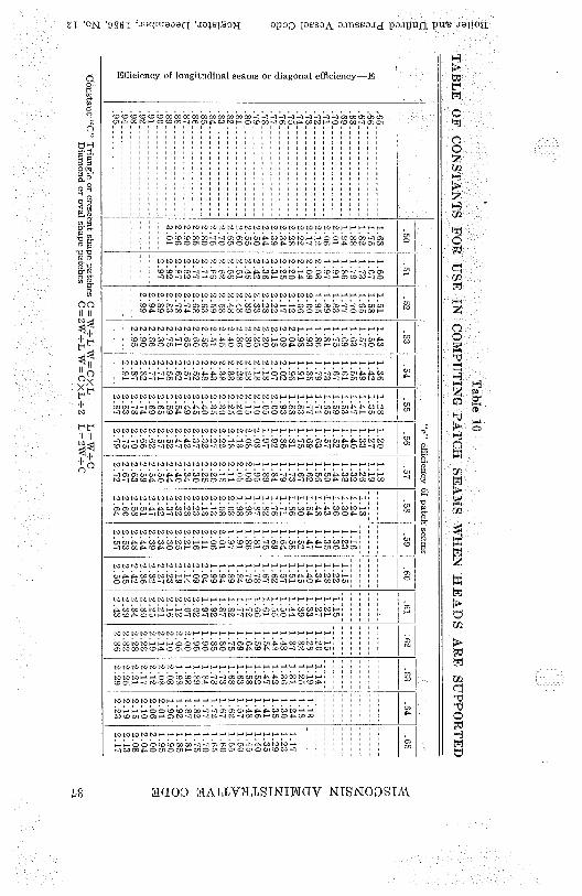
(1) The first thing that shall be taken into consideration whenproceeding with the design of a patch is whether or not all of theend stress is to be carried by the patch; in other words, whether theheads are supported or unsupported. In drums of water tube boilers,the full end wise stress has to be carried by the shell plates and thepatch seams, whereas in shells of horizontal tubular boilers some ofthe .end wise stress is carried by the through rods, tube or flues, andconsequently there is less stress on the shell and patch seams. It isevident; then thata patch in the one case need not have the samewidth for a given length as in the other case. In other words, differ-ent constants may be used in determining the width. Tables 10 and 11take into account these 2 different conditions.
(2) The angle of a patch when laid out in the flat does not changewhen formed to the curvature of the boiler, therefore, the diameterof the boiler does not need to be aien into consideration in the de-sign when the provisions of item ( ) p are met.
(3) (a) A patch shall be laid out in the flat and then carefullyformed to accurately fit the contour of the boiler where it is to beapplied.
(b) Patches shall be of the same thickness as the original thicknessof the plate they replace.
(4) (a) Seams exposed to the products of combustion shall besingle riveted lap construction.
(b) Seams not exposed to the products of combustion shall be dou-ble riveted or constructed similar to the original seams of the boiler.
(5) (a) Patches exceeding 24 inches in length shall have theproper width as determined by the rules herewith.
(b) Patches 24" or less in length shall be triangular, crescent,diamond or oval in form and the width shall be at least twice thelength.
(6) (a) If it is found that a patch would extend extremely highit may be shortened in width to the extent that no more than 4 rivetswill be in a longitudinal line, as shown in Figure 3.
(b) Likewise, to avoid the necessity of calking in sharp corners, apatch may be shortened in width to the extent that no more than 4rivets will be in a longitudinal line, as shown in Figure 3.
(7) (a) If it is found that a patch would have to be 60 inches ormore in length consideration shall be given to the use of a sheethaving a width equivalent to % of the circumference of the boilerand the longitudinal seam : shall be of a design ?similar to the designof the original seam of the boiler.
(b) In designing patches, it is not necessary to deal_ with anglesin the term of degrees, but merely with the dimensions of the tri-angles forming a -patch.: The relation between the length and widthprovides certain fixed :constants that have been tabulated and 'desig-nated as Tables 10 and 11. The constant is the figure by which thelength shall be multiplied to determine the width.
Boiler and Unftred Pressure Vessel Code Register, December, 1656. No. 12

^t
'WISCONSIN AD MINI STRATIVL CODE S
Fig. 2 Fig. 3
TRIANGULAR PATCH Showing, how patch may beseam on bottom of boiler
short-
girth
rt-Att gir b
ened girthivise provided no more than4 rivets are in a line parallel with the
(insde) as viewed from outside of longitudinal seam.boiler
N
:^ Scarf., >a
^o to w o am
iOi0 I ^10 .i 86u
O 10 1 i h 6 71O 10 W 000 ". W N,0000'0 2 ' Enlargement o
o jo of Scarf o 000 10 X00 10
O O 10 10
A'p0o io ^^ OD
iO 2 i
o Longitudinal-t . ^o B' pit° 1O°^,(.,.P Io /0 10 I
d W 0 to
°o L - 0 18°°° ^^ a oo
toio p
1° o @ I ,
7tI pp
°°°O .^YM ^^ .: iO 1 ' lC
° _6
o C ° +Longitudinal—+- `Bo ......... L
,1W course iO 1sheet Patuh plate) ;2nd course W
sheela
W_ Section Thru t A - B
Section Thru t A-B
Pig. 4 Fig. 5
DIAMOND SHAPE PATCH TRIANGULAR PATCHAt centre of sheet (inside)
At head seam and blow-off on hot-tom of boiler (outside)
1
C '
C
/1;—Z
0
O^ 0,,
-22;
lo
•oop^ w ^bd.
X00 —Long'ituc3inal—, Ai
o00 ----- 2 ------ I o I
00 - L----------- a9 >I°000 f 0 0
0000 00 W
o 0 00
00-11- :Scarf,o
^, ca ham G iQ the
° plafe
Soctlon Thru A-B-A'
Boiler and Unfired Pressure Vessel Code Register, December, 1956. No. 12

Fig. 6
CRESCENT PATCH
At Girth Scam
^z
;o <C
T_K -00p 10
^O i0
IW
I0 2 1
`10 r
AB-1-;_r-j
I
,00,^,o
°axle —^--- C
ioO 000000^o
ao Longifuo/ina/ r 1
r L 82 W
S L
010 0
C'
Fig. 7
OVAL PATCH
it ,-C
34 INDUSTRIAL COMMISSION
(c) If a patch is diamond in shape, it is considered equivalent to2 triangular patches and half the total length is used in determiningthe width.
(d) As the angle of a patch as laid out when flat does not changewhen formed to the curvature of the boiler, the diameter of theboiler does not have to be taken into consideration in the design.
(8) (a) In laying out new patches over 24 inches long, it is rec-ommended that they be triangular or diamond in shape, as may berequired for the particular job, with definite ,straight line sides, butwith the corner's properly rounded out to permit proper calking, asillustrated in Figures 2, 3, 4, and 5.
(b) Where the length designated as "L" and the width designatedas "W" is measured is also shown in Figures 2, 3, 4, and 5.
(9) (a) Rivets, patch bolts or staybolts may be used in "riveted"seams surfaces that are stayed or braced, provided at least one rivetor patch bolt is used between adjacent staybolts. The riveting shallbe completed first.
(b) Rivet holes may be countersunk in patches on shells that havebraced heads, if desired, without materially affecting the calculatedstrength of the patch. The angle of the chamfer with center line ofthe rivet hole shall not exceed 45 degrees and the depth shall notexceed half the thickness of the plate.
(10) Where patches have already been applied the problem is todetermine : the effective diagonal efficiency. If the 'seams are allrounded, that is to say, the patch is crescent or oval in shape, thelength "L" shall be taken between the center of the extreme two
t th 1 t d' al ter 1' a d 4-1, dth "W" 1, t thi ive s on e ongl u m een me n e- e ween ecenter of the extreme two rivets on the girthwise center line, asillustrated in Figures 6 and 7.
History* Cr. Register, December, 1956, No. 12, eff. 1-1-57.
Boiler and Unfired Pressure Vessel Code Register, December, 1956. No. 12

«W ISCONSIN ADMINISTRATIVE CODE 35
Ind 42.53 Material for riveted patches. (1) Patch material shall beeither fire box or flange steel. Structural steel shall not be used. Therepair shop shall produce a copy of the manufacturer's mill test re-port of the material to be used.
(2) The material shall contain the steelmaker's brand. If only partof a plate is required and this part does not contain the brand, thebrand shall be transferred to the patch plate in the presence of anauthorized boiler inspector or a representative of the plate manufac-turer, before the plate is cut. Rivets, patch bolts, or staybolts, shallbe of material of standard quality.
History: Cr. Register, December, 1956, No. 12, eff. 1-1-57.
Ind 42.54 Workmanship on riveted patches. "(1) All patch platesshall be placed inside a boiler shell or drum where exposed to theproducts of .combustion and where deposits would be pocketed. Wherea patch plate includes the part to which the blow-off is attached, thepatch shall be placed on the outside.
(2) All defective material exposed to the products of combustionshall be 'removed and properly trimmed to provide for neat work-manship in attaching the patch. Defects not exposed to the productsof combustion need not be removed unless necessary to insure a work-manlike job.
(3) A distorted sheet which is to be , patched shall first be setback straight as much as possible before proceeding with the cuttingout of the plate so that the patch may be kept as small as possible.
(4) The edge of a patch shall be beveled by planing, chipping, orgas cutting before applying it to the boiler. Rivets shall be drivenby gun, if at all possible.
(5) All rivet holes shall be drilled full size or the holes may bepunched not to exceed i/4 inch less than full size for plates over 5/16inch, and 1/s <,inch :less for plates 5/16 inch or less in thickness„ andthen reamed to full size with patch in place. Rivet holes are usually1/16 inch greater in diameter than the normal diameter: of the rivetbut a 1/32 inch difference is preferable when the rivets are of uniformsize.
(6) If seal welding is used, it shall be laid in a single bead with athroat thickness not less than 3/16 inch, nor more than 5/16 inch.The patch shall be tight before seal welding under a hydrostatic testequal to the operating pressure.
(7) Where 3 plates have to be lapped at the corners of a patch, themiddle plate shall be carefully scarfed to a feather edge the entirewidth of the lap, as shown in Figure 2.'
History: Cr. Register, December, 1956, No. 12, eff. 1-1-57.
Ind 42.55 Calculations for riveted patches. (1) First the length Lof the patch shall be determined. The dimension is, of course, gov-erned by the area of the defect. Next, the normal efficiency, e, of thesingle-riveted seam that is to be used in the patch shall be determinedfrom Table 9. This is governed by the thickness of plate and diameterof rivet holes.
(2) After determining the length that a patch shall be, the nextstep is to ,determine what the width girthwise shall be. This is foundby multiplying the length by the constant, C, as shown in Table 10or 11, depending upon the type of boiler to be repaired. These tables
Boilera.nl I7nfired Pressure Vessel Code Register, December, 1956. No. ]2

36 INDUSTRIAL COMMISSION
give a''constant C for a given efficiency, e, of patch and efficiency, E,of longitudinal seam.
(3) To determine the longitudinal efficiency of an existing patch, I,and W shall be measured, also the pitch, p, and diameter of rivet, d.W "divided by L will give the constant C. Table 9 will give e. Thenunder e in Table 10 or 11, depending upon the type of boiler to berepaired, fi the constant C. Then whatever E at the left is foundis the lonYudmal or allowed efficiency of the patch seam (See sec-tion Ind 42.56).x°'
Table 9EFFICIENCIES_ OF SINGLE-RIVETED SEAMS
Plate Rivet Hole Pitch of Efficiency ofThickness, t, Diameter, d Rivets, p Seam, e
11/16 1 % 63.39/32 Y4 17/ 60.06/16 % 17/8 (10.011/32 13/16 1-15/16 58.0'''/s 13/16 1-15/16 57.013/32 j 2-1/16 57.57 ;! 16 15/16 2% 56.01/32 15/16 2 % -55.5r G 1 ,.2% 55.7
1-1/16 2 % 53.019/32 - 1-1/16 2Y 52.8.d 1-1/16 2% 50.521/32 1 % 2-5/16 51.411/16 1 % 2-5/16 51.4
Tensile strength assumed at 55,000 psi . and shearing strength at 44: .,000. psi..'.History: Cr. Register, December, 1956,' No. % 12, eff. 1-1-57.
Ind 42.56 Examples of calculations ' for riveted patches. (1) DE-SIGN OF PATCH FOR HORIZONTAL-TUBULAR` BOILER. (a) A patch is to beplaced in the fire sheet of a horizontal-return tubular boiler havingshell plate 7/16 inch 'thick, a longitudinal seam efficiency of 74%,and a length of patch of 36 inches. Find the width W of patchto be applied so that there will not be any reduction in pressure, usinga single-riveted seam of normal design.
(b) Referring to Table 9, ii is found that a 7/16 .inch plate with15/16 inch diameter rivet holes, pitch 2 3/4 inch, gives a seam effi-ciency of 56%.
(c) Referring to Table 10, E-74 and e-56 give a constant-C-1.75;then width W:= L X C 36 X 1.75 = 63 inches.
(2) PRESSURE ALLOWANCE ON AN EXISTING PATCH FOR HORI7.ONTAL-TUBULAR BOILER. (a) A crescent shape patch has already been installedon a horizontal-tubular boiler. It is found to be 30 inches lon g and48 inches wide. The seam is noted to be single-riveted %with 13/16inch riveted holes pitch 1-15/16 inch. The boiler shell plate is % inchthick. The longitudinal seam is of the double-riveted butt-strap typehaving an efficiency of 82%. The safety valve is set for 125 poundspressure. What maximum pressure should be allowed on the boiler?
(b) Referring to Table 9, it shows that the normal efficiency of thepatch seam is 57%.Boiler and Unftred Pressure Vessel Code Register, December, 1956. No. 12
no;
wd
n
a^w w.
owRmo°
o^c^
N ^
roNm^m
m^N
(D
nnto
' I' rr^u0nxxrrLo
rrII II
n
ZZ * ON '9 9 6T `,taqutaoaQ apoD Iassa11 oanssaaa po.t flufl,put- a9llog
His
rl^
Lo4.^^
n0
HZHyJO
fynlJ
lld
roC,H H
V ^
IDHxlJivHi^
pC
^W^WW
l^L
LIU
fR
^^yy`i
H
Efficiency of longitudinal seams or diagonal efficiency—E
OCO CO GOCO tOWW WOJ GO GOW00000011 V- Il-JNN : N: O: TO^Onto H OOW 11 CT ^P W LV F A O 10 W11Cn iPWLJNOCO 00 11 cn
W LO Wtototo to to to to Lo to to to to to to!o to to. F+..NOCOOW W11G^1Cn W W Lo W-Cn,P -00.O . 1^+1oG^QGio cn outo^Pm^Pmlolrol^^Pmrocn oo - °
M Lo Lo b0 to of Ito vo LV to ^^LVroroto^^^Hr^r+rr-^OtDWOJ-^] ^111 Cn G^^P ^P wW to tv l-+ ooID :DW111T ^1LO ltot r^l lolf+ llol^cn QiPm Wl^lcowlQ a
to toNto toLoLOMNLoLonltolototoLoloN/-^Nl1F+F+F+F+i cOOW W1111Cn GC^P rPW WLO LONh + 000OW W111 Vt U^ ^^ O^fOW W^P LAWCD GJW WCO UJWLV 1LO10Cn tDW1QCT OOH ^
r [^! N N Lo LV [o Lo Lo N to Lo Lo Lo to [o to lV N to F + F+ F+ F+ h+ l-+ F+ F+ F+ h+i tO CO'bW1111G^UC ^P ^P WWIV to Fd OOtO COW W111^n G•^ WG,Q1Qa^enQlrenoloenocn en .P WW1r3 G^enW1oW
n. tv to Lo to LV roLV LO to LV tv L.^torotororon^rrr^+r+^^.-^r^^+LU
^DW9J-^1111 U, DP Co W[O toNWO O<O <O w--1--11aG^4DPW 1^r-+ 1N11 to 1 LOW W W W W W W WI NIF+ CPO Co I L-'Cn Wlo1
Nio NNNLo IO t'!o!o Lo W Lo Io!o!o
N CJ ill F+ F+ F+ N F+ f , 4, N F , F, F-oom1111 UtUC^P^4 4w Co M to l-^Y 00<0000o 1-1 U1 iP4 GJ Lo ^1W00 ^P t0 [n O^ Gt O Q, O GC O GiO.10 W W W1 I COWL- `CI^GO
to W to toM Lo LS M Lo Lo N Lo to LV IONHNNNNNNHHNN HN (per11111tH CT ^P ^P WCJNlV M^4^Q OCD CDW W111cn GL WI oWP M
1OCn01C^11V-1 LO1LV1toW WOOWll^14-^Cn COW 1lV CnOW10 ^..^..
Io Lo to lo N to [o to Cv to to N N lV IV I^ N F+ I^ F+ F+ t+ F+ 1-^ F+ t^ 1^ F+ F+ k+ F+111GC UC C.n ^P DPW Wto tv F + H OOCD WW1111cn Cn DP W to h+w G^
1
tj'y.
N1WeO ^PO^PO^POGtoG^^G^oG^eO^eOW1LO1o^PwloleOW ^
^to Nlo NloNLO [^NIV N[o [o IONNHHHHNNH NHNHNHi ^O>O: Vt VC iP iPwwi^ivNi-^oocO CO CO x :.l ^lmmcn iP iP Co wiO i GC w^P01i-+ 1NIIV OOWOOW yJW W W 1 to 1L-'104 GO WI OAP
Lo tv [o L^ Lo LO [v to to Nlo LV N F1 F+ N N N F+ N F+ N N H N N H N^ ^.C.n UC^P iPW WWNLO L+f+ 000O CD'yJW y Q>1cn fT ^P DPW Wtv I-+^ GC Hw1WOO ^P CO ^POUt1-`1F+ 1 F+ 1F+ 1^-+ fT CD ^P'.Y IV 11^000W1i O P
^i000'C4,P, ww to io l-+ M O000 c0 co w --1-J Q1 O>o, Cn iP .P w io ioo01to1ro-1WCO W1LV IF-`000 ^P'w to Uti i O
lo!o Lo i ll to to io!o to[o r
F+F+HNL-+-,H --- -H`h'r'i^P w w w to toNNO0w N w w--1 . 1 O OJ OC C, ;P w W io i'oWCOrPOCn I-`11o1 to 1N 1to1 N 1N GC OAP CDW 1F+w
loNlvloNNlo to [o FA H HNH1-+ NHNNHF+ F-`H HH^W Co Lo to WW 1 io Lo Ni 1C71[oWOJO^OC.n OCJCOG^OCn tb ^P NiP (% Wllvl O:ni
NN CJ LO!111 No HNNNF+NNF+HN H1-+F+HN^L LOto.. 0000 tD OOW1111C.n U•^^PW WlV F^`I-`i ^'CO U1 h+ 1loWW WWCO DPW W00 WOO lolly li-+cnW^i W
tv LV [o ro ro LOHwrr^+rri-+^^+ r ^+^+rrrr^NL-- - 000D CO 00W1111 4;pP W io h+ F+ i i 1WCD GJOIF'1LV 1LO1ty 11V 1601 ^-+ CTO^PW W^ ^ ^'
Lv to LO to lV F1HNF+HN^-`H1^NHNF+NH^-+^H NOOOCDW W^01-^111Cn fT rP x'^WLJ IONi 11WW^P QGIQ GPI-^cn oo^o G^ocno v^COWI^ G`
Lc HQOO `[AIIVUISINIIi GV NISNOOSIAk

38 INDUSTRIAL COMMISSION
9^
Wq
Qr
^i
C!1
^pryMy
W
U]
^i
F^9
U:
y Qr
F
^nW
Uzrw,,
H
FV -yyH
UF^
In ^<r1'1ry NOmoam000 tD -o lnmmm-i^ rrr li cNOt 1n
.r Nm1 1 1]1n :91'7 mrn/>otiNmllalnot-wmo,-+^.iHN.-1.-r .aNMrl .-1 .-1N NNNNNNnINNNmm
1 i^CD Inm O - 1<) i t NO c1O/: W mt l O]^WO c )ci1DN m d1 If] tD t [ e,0 0: 0 0 .-1 N m 11 1J IfJ :O l op O) O.i N19
.-1 '-r H H - .-1 .-1 .-i'.-1 +y N N N N N N N N N N N N m m m
m icDO^n<trN.-pmt- cD d. m.-ImNtiwd l N ^.-Immw^NC,rr-I Nm 11' 1119,19
t, 09 M. C .I.iNc d CD I; CG O>c . Nc Vrcim^ci ci ci ci ci N Cy^MM m mm
N iNmN MNr mW Do11 a O[ OOl - "i —^
19 oc
1.+Nm<t1 ^r..mNNCOrnc. -INmm^ln cD r - Nm.i-----f--Hf.V CV GV Cpl :1 Cl Pl clN CiNmmmm r
6H mD^ OC1+COO M 1 In1,7
OO 1-- 1m OO Mcc'i11 ^ 11 m^..i .-I .-I .i .-Ii...i .i lnlNNCi CV CV NlV GVNm mmm M ^
O ^Hl rl .+am t-fD ^OmN.+O al l-tD I!?m minm CD l-t-O:ar— r r
ci0 ' 19 1-9L Wll OC -.-INmc'"I[. (p t-1p 1101-ici.-i e-i .-1 H -.-1 .-r .-r .-1 — N N N N N N N N N N N mm m m
N'd1 NNN OOII CO t-mc N OOIm C-1 `7c alm cN NCO+-1Nm^ 1n u^<o c- mv, o.-+Nmca^ln ^,t m.-INm +^ r
m - -- - -i -.-i - -i - c^ ci ci cv c^i c^i c^ ci ci ci ci m c^ c*a cn
:^,ro
^1n
^<nmN.-^/:moot-cn In ^+N N.-+,-^,-rNmlrtimaNma1 ^'^cDCt-corno.-^Nmwlno^cowo.-INS
°'0
.-i >-+.-i .1 .-^ .-i .^ .-^ .-i N ci ci ci ^i ct ci N c^ ci M m m
^ tiIn lnNm.-+oornrnrnNCn u>>n In lr.NtioNN^n ^ r
^ ^ m 1l ^nmi oommo.iNmi^ln ^n^corn.-INm^rd
(.
(UC H .-1.-1 .^-I .-I .-1 .-1 .-i N N CV GV GV 4V C pl GV N GV G+J t+'J C.1 t.'.1 1 r r i
4pj ,^ k'J 1t ll m ta ll .. . . . . . 1 c0N c t Cn c 1 r11 lnmi mrno.-INm t • ^in cD OO 1^o.-^Nmci ci .iNCi ci ci ci c^i cimcomo^ r
cf;n <D<O.[J tD 11 11 m m N N 1.111 1900 11 tH i.^m Naomo.i Nmm^totioow -INmw
.-^rl .-1 e-1NGi P1 N N N N N m m
;^ X00 OO tD tO tD tD 101900 O t WO0'C^ tO t-
00^0.-INmcN 19 1
p l^CS10NNcM-1.-I rINN NN N N NNNm m mm r r r
V
N.
^ ^ .-1 .--iNNNNNNN NNNmmmm 1 r
N mmmcOm M m l.J tOl Cirr r^
Ci-rna.-IN C-.^1!1n
lDN 19 O 'a chi! r r
.-IN N N NN N N N N m m mn+
OCO---C---mt--N O1' N N N N N N N N N m m mm
O NO 11 C .-Im1Jb m^CD L` m N O N- 0 L 011 mmNN N N N NNNmmmmm 1
vi tO r oomo,-i ci o'J <r to co t-r ao ci o,-i ci o^I I Iti colr oo aio,ti Chi c+Jd uiacD tDmmC o-L t- r- N^ t- t L'7 m m oo oO CO 09 co m 09 rn rn rn Olrn
a—Bau@pMa luuo2utp .lo sucsas iuuipnji8uoito SouaiaLgai
Boiler and Unfired Pressure Vessel Cod e, Register, December, 1966. No. 12
WISCONSIN ADMINISTRATIVE CODE 39
(e) If the efficiency is not found in the table, refer to any otheravailable table or determine it in the customary manner described insections Ind 41.50 and Ind 41.51 of this code.
(d) Divide the width of the patch W := 48 inches by the lengthL = 30 inches to find the constant C 48/30 = 1.60.
(e) Follow down column e := 0.57 of Table 10 until 1.60 is found.It will be noted that this is somewhere between 1.56 and 1.62 rep-resenting E somewhere between 0.72 and 0.73. As the di fference be-tween 1.56 and '1.62 is 6, and the difference between 1.56 and 1.60 is4, E will be 0.72 plus 4/6 of 0.001 which is 0.7266.
(f) The pressure approved varies directly as the seam efficiency.Accordingly P = 0.7266/0.82 X 125 = 110 pounds per square inch.
(g) If this allowance interferes with the operation of the plant,the patch will have to be replaced by a new one with proper di-mensions giving a diagonal efficiency of 82 %.
(3) DESIGN OF PATCH 'FOR WATER-TUBE BOILER. (a) Sections of theplate having a'total length of 36 inches (measured at the pitch line)are to be removed on each side of a girth seam. The patch is to bediamond or oval shape. The 'shell plate is 7/16 inches thick and thelongitudinal seam is 'double-riveted butt strap construction, having anefficiency of''82%. =What 'should be the width of the patch for main-taining the same pressure allowance?
(b) Referring to Table 9, it shows that a single-riveted lap seamwith 7/16 inch plate, 15/16 inch diameter rivet holes, and 2% inchpitch has a normal efficiency of 56 01o.
(c) Referring to 'Table 11, it shows for E 0.82 and e 0.56,the constant C is 8.16.
(d) Then width W .- C X L- 2W = 3.16 X 36 - 2 := 56.88, say 57 inches.
History: Cr. Register, December, 1956, No. 12, eff. 1-1-57.
Ind 42.59 Welding procedure. Manufacturers, owners or contractorsundertakin repairs under these rules shall have available for theinspector a written welding procedure specification that shall be fol-lowed in milting the necessary repair and also a record of procedurequalification teats. Welding p ocedure speci fications shall have beenprepared an p d//qualified incoxdance with the requirements of sec-tions Ind 41`60 and Ind 4 .5/1'of this code under Welding Quali fica-tions, section Ind 41.50–(9)." Repairs by fusion welding on low, pres-sure steam and hot water boilers
sa 4exempt from the provisions
of sections Ind 42.50 through Ind 42.79,' exceptexcept that a qualified weldershall be required.for suck'repairs gfid the repair7^shall co m/tosections Ind 42.61; Ind 42.62, Ind 42.63; Ind 4 !64;. and Ind 42.78.,'`
History: Cr. Register, December, 1956, No. 12, eff. 1-1-57.
Ind 42.60 Welders. (1) WELDER QUALIFICATION. Manufacturers,owners or contractors shall have available for the inspector recordsof welder qualification ests showing that each welder to be employedon the
" ^kvo , has sat' acttorily passed tests as prescribed in sections
Ind 4150 nd Ind 41. 1%f this code under Welding Quali fications; forthe type of ,filler metal to be used and for each position in whichhe will be called upon to operate in making the repair.
(2) WELDING TESTS, MANUFACTURER'S, OWNER'S OR CONTRACTOR'S RE-SPONSIBILITY, INSPECTOR'S DUTY. Preparation of welding procedureBoiler and Unfired Pressure Vessel Code Register, December, 1956. No. 12

40 INDUSTRIAL COMMISSION
specifications and the conducting of tests of procedures and weldersshall be the responsibility of the manufacturer, owners or contrac-tor. Before repairs are started, it shall be the duty of the inspectorto r satisfy himself by examination of the written welding procedureand records of : qualification tests that procedures and VyWgIders havebeen .'properly qualified as required in section Ind 41.50 (l1) r Witness-ing of the tests by the inspector shall not be mandatory but he shallhave the right to witness such tests when he deems it necessary. Theinspector : shall also have the right to call for and witness the makingof test plates by any welder, at any time, and to observe the physicaltesting of such plates.
History: Cr. Register, December, 1956, No. 12, eff. 1-1-57.
bid 42.61 Rules for welding. The repairs that may be made underthese rules are limited to steels of flange or fire box quality havingknown weldable quality and further limited to carbon steels having• carbon content of not more than 0.35% and low alloy steels having• carbon content of not more than 0.25%. Structural steel shall not beused. The welding_ of high alloy material and non-ferrous materialshrill be done in , ccordance with the requirements of sections Ind41.50 '"tnd Ind 41.51iiof this code for boilers and unfired pressurevessels.
History: Cr. Register, December, 1956, No. 12, eff. 1-1-57.
Ind 42.62 Prohibited repairs. A welder shall not make repairs Ana plate thi ness in excess of that permitted under sections Ind 41.50 •and Ind 41.51\f this code for Welding Qualifications. A welder _shallnot make repairs on a material that is not covered within his qualifi-cation tests.
History: Cr. Register, December, 1956, No. 12, eff. 1-1-57.
Ind 42.63 Procedure. Groove welds shall completely_ penetrate thethickness of the material being welded. If possible, welding shall beapplied from both sides of the plate or a backing strip or ring may beused to insure complete penetration. Manually applied welds shallhave a con\ • eN surface on both sides if applied on both sides of theplates being joined, or on one side if welding is applied from oneside only. Valleys and undercutting at edges of welded joints shallnot be permitted. The reinforcement may be chipped, ground, ormachined off flush with the base metal, if so desired, after the weld-ing has been completed.
History: Cr. Register, December, 1956, No. 12, eff. 1- 1-57.
Ind 42.64 Defective weld. In making a repair to a weld that hasfailed in service, the defective weld shall be removed by chipping,grinding or gouging until sound metal is reached on all sides. Theresulting groove 'shall be filled as required by the applicable weldingprocedure.
111story: Cr. Register, December, 1956, No. 12, eff. 1-1-57.
Ind 42.65 Stress relieving operations. (1) In repairing carbon orlow alloy steels, when required by these rules and considered necessaryby the authorized inspector, thermal stress relieving shall be appliedto the completed work. The heat may be applied by any means thatwill raise the temperature of the material being heated graduallyp9iler and Unfired Pressure Vessel Code Register, December, 1956, No. 12

WISCONSIN ADMINISTRATIVE CODE 41
and uniformly to approximately 1,200 degrees Fahrenheit. (In theabsence of more 'accurate means of determining temperature, a dullred glow in daylight will suffice). This temperature shall be main-tained''for a period of one hour per inch of thickness of material.For circumferential joints, the area heated shall comprise a bandextending completely around the cylinder and having a width on eachside of the center line of the weld not less than 3 times the greatestwidth of the finished weld. For nozzles, the heated area shall comprisea circumferential band extending around the entire vessel, includingthe nozzle or welded attachment and shall extend at least 6 timesthe plate thickness beyond the welding which connects the nozzle orother attachment to the vessel. Under certain conditions other methodsof "thermal stress relieving acceptable to the authorized inspectormay be used. Under certain conditions preheating may be necessary.
(2) Upon completion of the stress relieving operation, the plateshall be allowed to cool at a rate not greater than 500 degrees Fahren-heit per hour divided by the maximum thickness of the welded part ininches, but in no 'case more than 500 degrees Fahrenheit per hour.This rate of cooling shall be maintained until a temperature ofapproximately 600 degrees Fahrenheit is reached, after which nor-mal cooling by exposure in a still atmosphere may be permitted.
(3) Thermal stress relieving of austenitic steels is a controversialsubject. It shall not be a tempted excep in accordance with the mc-ommendations of the nucturer of the material of the require-ments of sections Ind 41.50=and Ind 41`1 of this code.t"
(4) In lieu of thermal stress relieving of carbon steels, peeningor other methods acceptable to the authorized inspector may beemployed.
History: Cr. Register, December, 1956, No. 12, eff. 1-1-57.
Ind 42.66 Cracks, permissible welded repairs. (1) Cracks in un-stayed shells, drums or headers of boilers or pressure vessels may berepaired by welding, providing the cracks do not extend between rivetholes in a longitudinal seam or parallel to a rivet seam within 8inches, measured from nearest calking edge. The total length of anyone such crack; shall' not exceed 8 inches. Cracks of a greater lengthmay be welded, provided' the complete repair is A adiographed andstress relieved in accordance with section Ind 4ft5.' /See Figures 8and 8 (a) for Acceptable Methods.
(2) Cracks of any length in unstayed furnaces may be welded,provided the Ids are thermally stress relieved in accordance withsection Ind 42.65 k Welds applied from both sides of the plate shall beused where possible. Welds, applied from one side only shall be sub-ject to the approval of the authorized inspector. Field repair ofcracks at knuckle or turn of flange of furnace opening are prohibitedunless specifically approved by the industrial commission. See Figure9 for Acceptable Methods.
(3) Cracks of any length in stayed areas may be repaired by fusionwelding except, that multiple or star cracks radiating from rivet orstaybolt holes shall not be welded. See Figure 10 for AcceptableMethods.
History: Cr. Register, December, 1956, No. 12, eff. 1-1-57.
P,oiler and Unfired Pressure Vessel Code Register, December, 1950,. No. 12

42 INDUSTRIAL COMMISSION
Ind 42.69 Corroded surfaces and seal welding. (1) Corroded -areasin stayed surfaces may be built up by fusion welding, provided theremaining plate has an average thickness of not less than 50% of theoriginal thickness, and further provided that the areas so affected arenot sufficiently extensive to impair the safety of the object. See Fig-ure 11 for Acceptable Methods.
-(2) Corroded areas around manhole or handhole openings in eitherstayed 'or'unstayed plates may be built up by fusion welding, pro-vided'the average loss of thickness does not exceed 50% of the originalplate thickness and also provided the area to be so repaired doesnot extend more than 3 inches from the edge of the hole.
(3) Corroded areas in unstayed shells, drums or headers may bebuilt 'up by fusion welding provided that in the judgment of theauthorized inspector, the strength of the structure has not been im-paired.;,See Figure 12 for Acceptable Methods.
(4) Edges of butt straps or of plate laps and nozzles or connectionsattached by riveting may be restored to original dimensions by weld-ing. Seal welding shall not be used except with the special approvalof the authorized inspector, and in no case where cracks are presentin <riveted areas. See Figure 13 for Acceptable Methods.
(5) The ends of tubes in fire tube and water tube boilers may beseal welded provided they have not been reduceA more than 0%in thickness, and requirements of sections Ind 41.50 land Ind 41Vofthis code are satisfied. See Figure 14 for Acceptable Methods.
History: Cr. Register, December, 1956, No. 12, eff. 1-1-57.
Ind 42.74 - Re-ending and piecing tubes. Re-ending or piecing oftubes or pipes in either fire tube or water tube boilers is permittedprovided the thickness of the tube or pipe has not been0 eluced bymore than 10% from that required by sections Ind 41.50 "and Ind41.1 Vbf this code for the pressfii to be cared. In all cases therequirements of sections Ind 4 50'V and Ind 41.51 3of this code shallbe met.
History: Cr. Register, December, 1956, No. 12, eff. 1-1-57.
Ind 42.75 Patches, material. The material used for patches shall beof the same general quality and have at least the minimum physicalproperties of the plate to be patched. The thickness of any patch shallbe at least equal to, but not more than, 1/s inch greater than the platebeing patched.
History: :. Cr. Register, December, 1956, No. 12, eff.. 1-1-57..
Ind 42.76 <Flush or butt welded patches. '(1) Flush or butt weldedpatches in unstay d shells,' drums or headers shall be 'radiographedai 'st ess relievd o conform to the requirements of sections 'Ind41.150 `,-And Ind 41.51 of this code for new construction. Subject to theapproval of an authorized inspector, peening or other methods ofstress relieving may be substituted for thermal stress relieving. Sub-ject to compliance with this requirement," no limit is ' placed ondimensions or location of such patches or on the thickness of thematerial. When the longest dimension of a patch does not exceed1.6 times the plate thickness or a maximum of 8 inches, radiograph-ing and stress relieving is not required. See Figure 15 for AcceptableMethods.Boilor and Unfired Pressure Vessel Code Register, December, 1956. No. 12

WISCONSIN ADMINISTRATIVE CODE 43
(2) Flush or butt welded patches or new sections may be appliedto stayed plates without limitation of size or plate thickness. SeeFigure 16 for Acceptable Methods.
History: Cr. Register, December, 1956, No. 12, eff. 1-1-57.
Ind 42.78 Lapped and fillet welded patches. Lapped and fillet weldedpatches may be applied to stayed plates provided they are not ex-posed to radiant heat. Lapped and fillet welded patches may beapplied on the pressure side of the sheet in unstayed areas, providedthe maximum diameter of the opening so repaired does not exceed16 times the thickness of the plate, but in no case larger than 8 inchesin diameter. See Figure 17 for Acceptable Methods.
History: Cr. Register, December, 1956, No. 12, eff. 1-1-57.
Ind 42.79 Stays. (1) Threaded stays may be replaced by welded-instays provided that in the judgment of the inspector the plate adja-cent to the stay bolt has not bee materially weakened by deteriora-tion or wasting Away. All requ elTents of the applicable section ofsections Ind 41. 0 And Ind 41.51 ' of this code governing welded-instays shall be met, except that stress relieving other than thermalmay be used as provided in section Ind 42.65.
History: Cr. Register, December, 1956, No. 12, eff. 1-1-57.
Ind 42.80 Additional acceptable repair methods. Repairs and repairmethods not discussed in the chapter shall comply with methods illus-trated in Figures 18, 19, 20, and 21.
History: Cr. Register, December, 1956, No. 12, eff. 1-1-57.
Boiler and Unfired Pressure Vessel Code Register, December, 1956. No. 12
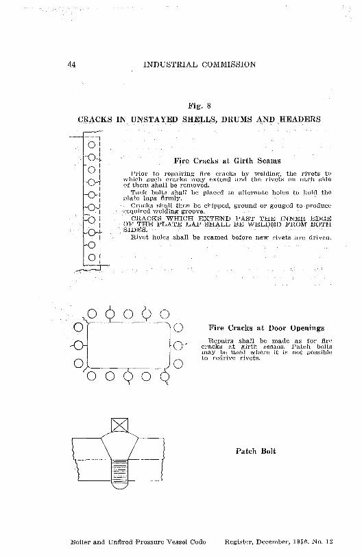
Patch Bolt
44 INDUSTRIAL COMMISSION
Fig. 8
CRACKS IN UNSTAYED SHELLS, DRUMS AND HEADERS
--,OII
IFire Cracks at Girth Seams
O I Prior torepairing fire cracks by welding, the rivets towhich such cracks may extend and the rivets on each sideof them shall be removed.
Tack bolts shall be placed in alternate holes to hold theMate laps 'firmly.
Cracks shall then be chipped, ground or gouged to produce
I required welding groove.I CRACKS WHICH EXTEND PAST THE INNER EDGE
OF THE PLATE LAP SHALL BE WELDED FROM BOTHSIDES.
1 Rivet holes shall be reamed before new rivets are driven.I
O!
0 0 00
0/10- 0
O Fire Cracks at Door Openings
Repairs shall be made as for firecracks at girth seams. Patch boltsmay be used where it is not possible
Oto redrive rivets.
Boiler and Unfired Pressure Vessel Code Register, December, 1966. No, 12

WISCONSIN ADMINISTRATIVE CODE
45
Fig. 8a
CRACKS IN UNSTAYED SHELLS, DRUMS AND HEADERS
^ Iii
Circumferential Cracks at Girth Seamsi
Caution: Before atteinpting• repairs care shall be takento investigate the cause of cracks of this type.- Weldingl shall not be used if "caustic embrittlement" is indi-cated. Multiple or star cracks shall not be welded.
If repair by welding is authorized, method for repair-i
ii
ing fire cracks at girth seams shall be used.
i
i
;0
Exam 1e of Multi le or Star C'rackinP P g
Cracks Between Tube Holes
In repairing cracks of this type, -welding shall beapplied from both sides of the plate if possible.
The tubes to which the cracks extend and the tubeson each side of them shall be removed and the crackschipped, ground or gouged to provide the required weld-ing groove. Tube holes shall be reamed before new tubesare installed.
Cracks in Headers
in repairing cracks of this type, welding may be appliedfrom one side. A backing strip shall be used if possibleto -insure complete penetration at bottom of weldinggroove.
Boiler and Un fired Pressure Vessel Code Register, December, 1956. No. 12

46 INDUSTRIAL COMMISSION
Pig. 9
CRACKS IN UNSTAYED FURNACES
Caution: Successful perform-ance of this repair requires aductile weld free from slag in-clusions, voids, cracks or otherdefects.
Cracks shall be chipped,ground or gouged to providerequired welding groove; rootof weld shall be cleaned bychipping or flame gouging andwelding applied from both sidesof the plate. Thermal <stress re-lieving is recommended.
Field repair ofcracks at knuckle orturn of flange of fur-nace opening is difFi-cult. It is 'recommended that this re-pair be made in 'a wellequipped shop.
Boiler and Upflred Pressure Vessel Code Register, December, 1956. No. 12
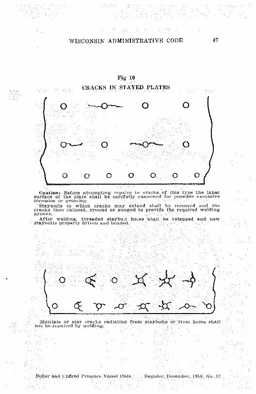
WISCONSIN'' ADMINISTRATIVE CODE 47
Fig 10
CRACKS IN STAYED PLATES
1
Q_`^ 0 --4D-- 0
O 0 O ® ® 0
Caution: Before attempting repairs to cracks of this type the innersurface of the plate shall be carefully examined for possible excessivecorrosion or grooving.
Staybolts to which cracks inay extend shall be removed and thecracks then chipped, ground or gouged to Provide the required weldinggroove.
After welding, threaded staybolt holes shall be retauped and newstaybolts properly driven and headed.
s 0 O
Multiple or star cracks radiating from staybolts or rivet holes shallnot be repaired by welding.
Boiler and Unfired Pressure Vessel Code Register, December, 1956. No. '12
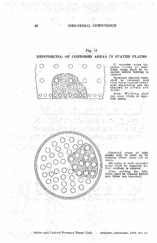
48
INDUSTRIAL COMMISSION
Fig.
REINFORCING OF CORRODED AREAS IN STAYED PLATES
O Oo o
O if corroded, area includes stayrivets or -bolts, these shall be, re-moved before welding is
:;: r..:;; >•:, applied.
o %Threaded staybolt'holes
shall be retapped anda '^` ''"' rivet holes reamed before
new staybolts are myr stalled or rivets are
driven.
00 0r j 1
0 0 Q O Q' 0 0 0 Note: Welding shall.. not cover rivets or stay-
bolt heads.
O OO O
0 0 0oO 0 0'o'.:00 ot'o0 0 00^01oo^/
Corroded areas of tubesheets may be built up bywelding where tubes act asstays.
All tubes in such corrodedareas shall be removed be-fore welding is applied:,
After. welding the tubeholes shall be reamed beforenew tubes are installed.
Boiler and Unfired Pressure Vessel Code Register, December, 1956. No. 12
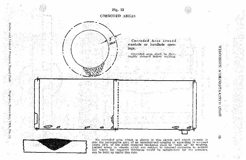
0
UZ
r
Fig. 12
CORRODED AREAS
H
C^Ozz
z
yC
O
t7
coNo corroded area which is shown in this sketch and which exceeds in
size the permissible area of an unreinforced opening or exceeding in averagedepth 50 1,1'0 of the plate required thickness shall be "built up" by welding.Larger areas in vessels which are subject to internal corrosion or erosionbut where the required thickness would be satisfactory for the pressure,can be built up under this rule.
r

50 INDUSTRIAL "COMMISSION
Trig 13
SEAL WELDING OF CAULKING EDGES
® 1,(i
1 ^01 011 1` O O 1
01®® 1
011®
1 ® ®®^
®j 1
O OO i1 1O
I,01
0 1 O O1
01 00
0 1 ®1 ®
O
Caution.—Seal welding shall not be applied if cracks are present inriveted areas.
Indications of persistent or recurring leakage may be a sigh ofcracking. No welding shall be applies. until a careful examination-including removal of rivets if necessary—leas been made of such areas.
Seal welding shall be applied in one light layer H practicable but notmore than two layers shall be used.
Threat approx. 1/1"
Boiler and Unfired Pressure Vessel Code Register, December, 1956. No. 12

WISCONSIN ADMINISTRATIVE CODE 51
Fig 14
SEAL WELDING OF TUBE ENDS
Seal welding shall be applied in onelight layer if practicable but not morethan two layers shall be used—Throatdimension shall' not `exceed 5/16".
Boiler and Unfired Pressure Ve,sscl Cork Register, December, 1956. No. 12

52 INDUSTRIAL COMMISSION
Before any effort is made to patch a bagged or deformed area theoriginal shape or curvature shall be restored as far as possible. Patch shallbe rolled or pressed to proper shape or curvature. Edges shall align withoutoverlap.
Flush or butt welded patches may be of any shape, an adequate radiusshall however be provided at corners if patch is rectangular. Sharp cornersshall be avoided.
Note: Patches shall be of material equal to the original constructionin thickness and quality.
Boller and Unfired Pressure Vessel Cods: Register, December, 1956. No, 12
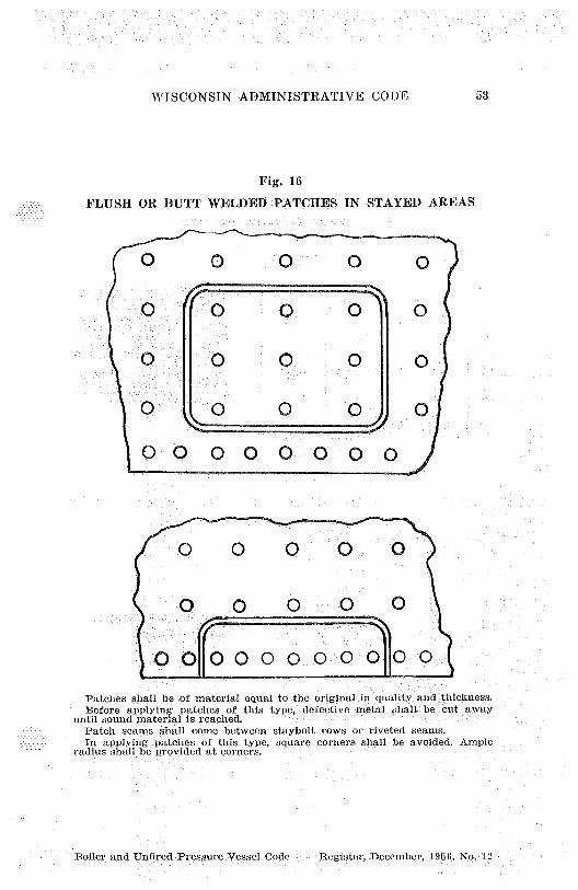
AVISCONSIN'ADMINISTRATIVE CODE 53
Fig. 16
FLUSH OR BUTT WELDED PATCHES IN STAYED AREAS
0 0 0 0 0
0
0
0
O 0 0 0 0 0 0 0-)
® 0 0 0
0 0 0 0 001
00 000 0. 0 0 0110 0
Patches shall be of material equal to the original in quality and thickness.Before applying patches of this type, ',defective metal shall be cut away
until sound material is reached.Patch seams shall come between staybolt rows or riveted seams.In applying patches of this type, square corners shall be avoided. Ample
radius shall be provided at corners.
Boiler, and Unfired Pressure Vessel Code Register, December, 1956. Nn. 'I

54 "' 'INDUSTRIAL COMMISSION
Fig. 17
LAP-FILLET WELDED PATCHES
0 0 0 0Patches shall be of mate-
rial `equal to the original inquality and thickness.0 0 0 If area to be patched in-eludes a' riveted seam rivets_shall be removed before
1' I patch
is `applied and newI rivets driven before patch isI0 0 10 0 welded at edges.
New staybolts shall be in-stalled in patched area, the
I heads of staybolts shall notbe covered by lwelding.
0 010 0 0 0 10 0 0 0 0'
Lap Fillet Welded Patch in\\ ; Unstayed Area
-4'I —MIN. LAP
Boiler and Unfired Pressure Vessel Code Register, December, 1956.' No. 12

IVISCONSIN ADMINISTRATIVE CODE 55
Fig. 18ACCEPTABLE REPAIRS FOR CORRODED OR WORN HEADS OF
VERTICAL TUBE OR SIMILAR TYPE BOILERS
000Op 0 p 0° 0
00 0 0 0 000000 000000 0 0 p 00
00O00000
O 00
O_
0 0 00 0 0
0 0p 0 00 0\ \ 00 0 °0 0p 0 p p i 00 0
0 0 00
1'0000 0000 0000 00001 00 p o p 00, ; OO O 0 p 00
0 0 O O 0 O\0000000/
3
0000000
z` -- - °E=1. Flush Butt Welded Head
With this repair the old head is cut close to the point of tangencyof the knuckle of the flange and the new head, previously drilled fortube holes-andbeveled for adequate welding groove is butt welded toflanged section of old head. Pack up ring, inserted in sections if neces-sary, shall be used to insure weld penetration for 'full head thickness.
2. Lapped and Fillet Welded HeadWith this repair, the new head is lapped under the flange knuckle of
old head, previously slotted as shown to admit ne«r head, then filletwelded at edge.
3. Segmental or Pie-Shaped Butt Welded Patch
13oiler c.nd Upfired Pressure vessel Code Register, December, 1956, No. 11

56 INDUSTRIAL COMMISSION
Fig. 19
ACCEPTED REPAIRS FOR INSPECTION OPENINGS
SPAN DARMANHOLE LPENINO
IZ-16 OR 11x15
A badly corroded manhole flange may be repaired by cuttin outflanged section and inserting a ring type frame a^,shown. Time ionsshall comply with requirements of sections Ind 41.50 mid Tnd_41.51 ofthis code.
Ring type frame may be fabricated and stress relieved in shop thenwelded inplace.
Rules for fl ush patches shall be complied with.
f ^
Plate lap should not be less than ?2".When corrosion has reduced thickness of plate arouml handhole open-
ing by more than 50% (average) a reinforcing ring shill be used asshown placed on the inside.
Boiler and Unfired Pressure Vessel Code Register, December, 195f,. No. 19

WISCONSIN'' ADMINISTRATIVE CODE 57
Fig. 20
SUGGESTED METHOD OF INSTALLING NEW FURNACE ININTERNALLY FIRED BOILER WHERE TUBES ACT AS
STAYS SUPPORTING. HEADS
0
AID z
> ) Nby
^' VwmR0
V ^ ^
S7^N
^'^ b4
wX09
cd 0
S r R
aw 9
V O
Nw
a>9Abo san oaN^ • p9
Boiler and Un fired Pressure Vessel Code : Register, December, 1956. No. 12
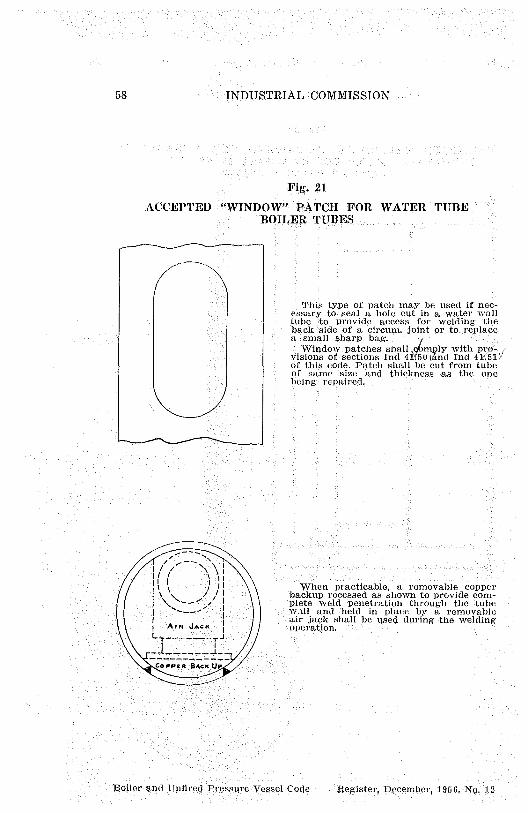
58 INDUSTRIAL COMMISSION
Fig. 21
ACCEPTED "WINDOW PATCH FOR WATER TUBEBOILER TUBES
This type of patch may be used if nec-essary to seal a hole cut in a water walltube to provide access for welding theback side of a circum, joint or to replacea small sharp bag.Window patches shall , bmply with pro=
visions of sections Ind l;and Ind 4 Y51.of this code. Patch shall be cut from tubeof same size and thickness as the oneTieing repaired.
D11
it
i l When practicable, a removable copper
/ I backup recessed as shown to provide com-
^ I plete weld penetration throughthe tubewalland-held 'in place by a removableairjack shall'be used during the welding
I operation.
-1-
U ►
Boiler and Unfired Pl•essllre'Vessel CoQe ZeKister, December, 19 5 6, No. 12