anass 2007 - template - hrvatska znanstvena … · web viewa calculation of the whole model (figure...
TRANSCRIPT
Josip SERTIĆ*, Dražan KOZAK*, Pejo KONJATIĆ*, Mato KOKANOVIĆ*
* J. J. Strossmayer University of Osijek, Mechanical Engineering Faculty in Slav. BrodTrg Ivane Brlić-Mažuranić 2, HR-35000 Slavonski Brod, Croatia
E-mails: {josip.sertic,drazan.kozak,pejo.konjatic,mato.kokanovic}@sfsb.hr
Abstract. Thermal stress can cause problems while designing power plants, especially steam boilers. The standards for calculation of the boiler pressure parts mostly determine only the calculation procedure for overpressure load. Other load influences, including the influence of thermal dilatation on the stress values in the boiler structure, should be dealt by the designer. The aim of this work is to present the whole procedure of stress / strain calculation in the steam boiler pipe. The stressed state in the pipe is the result of thermal dilatation differences. The analytical calculation for linear-elastic behaviour of the material was created, together with numerical one, where bilinear yield law of the material was supposed.
1 Introduction
The primary households waste represents not only a huge problem, but also an insufficiently used source of energy. Waste incineration is one of the possibilities how this energy source could be used. The central part of the waste incineration power plant is a steam boiler. A procedure of carrying capacity calculation of connecting pipes of the steam superheater (SH) of the steam boiler under the design name ''SITA TEES VALLEY'' [1] manufactured by Đ.Đ. Termoenergetska postrojenja d.o.o., is presented in this paper. The connecting pipes (Figure 1 and 2) connect the superheater with the collector header, and then with the next superheater. On one side, they are structurally fixed on the membrane boiler wall, and on the other side on the superheater collector header. Their bending is caused by temperature differences of the membrane wall and the collector header.
2 Description of the problem
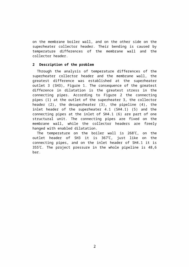
Through the analysis of temperature differences of the superheater collector header and the membrane wall, the greatest difference was established at the superheater outlet 3 (SH3), Figure 1. The consequence of the greatest difference in dilatation is the greatest stress in the connecting pipes. According to Figure 2 the connecting pipes (1) at the outlet of the superheater 3, the collector header (2), the desuperheater (3), the pipeline (4), the inlet header of the superheater 4.1 (SH4.1) (5) and the connecting pipes at the inlet of SH4.1 (6) are part of one structural unit. The connecting pipes are fixed on the membrane wall, while the collector headers are freely hanged with enabled dilatation.
The temperature on the boiler wall is 268C, on the outlet header of SH3 it is 367C, just like on the connecting pipes, and on the inlet header of SH4.1 it is 355 C. The project pressure in the whole pipeline is 48,6 bar.
1
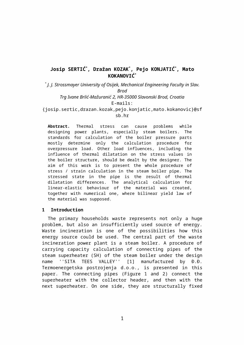
1 – membrane wall, 2 – outlet header of the superheater 3 (SH3),3 – inlet header of the superheater 4.1 (SH4.1)
Figure 1: Steam boiler of the waste incineration power plant
The material used for SH3 collector header, the connecting pipes and the pipeline, including the desuperheater, is P235GHTC2, while the material used for other pipelines, the collector headers and the connecting pipes SH4.1 is 16Mo3.
A calculation of the whole model (Figure 2) was previously made using Finite Element Method (FEM) under the assumption of homogenous and linear-elastic behaviour of the material [2]. The acquired stress values on the connecting pipes exceed by far the conventional yield point [3].
Due to these unfavourable calculation results, a reconstruction was needed, under the assumption that the value of stress would decrease after the extension of the connecting pipes. It was difficult to perform this operation since the structure has already been fixed at the construction site.
Another solution was to determine the yield of the material at the critical cross-section of the most loaded overflow pipe and to determine the existing carrying capacity of the pipe.
2
Figure 2: SH3 and SH4.1 superheater pipe joint
3 Analytical calculation of the necessary connecting pipe length
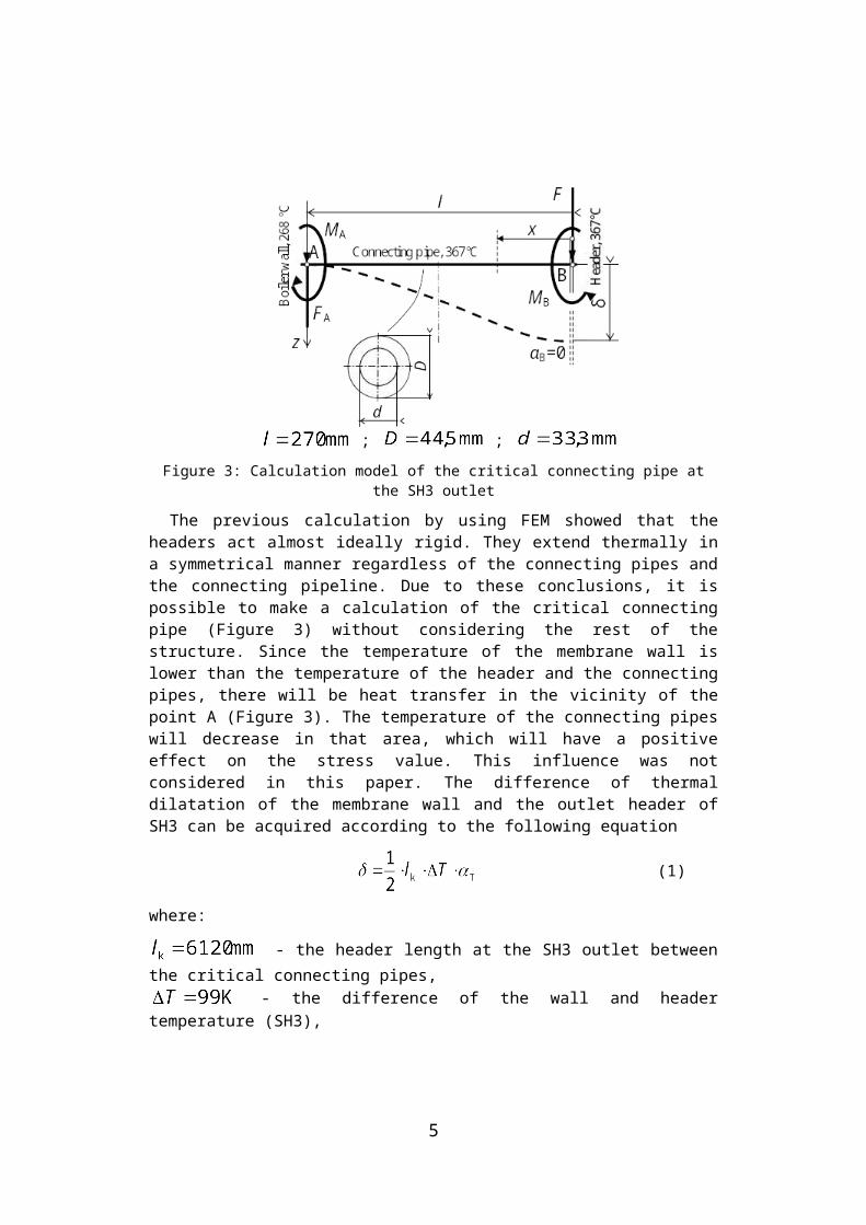
The most loaded connecting pipes are straight connecting pipes at the outlet of SH3 at the beginning and at the end of the header, Figure 3.
; ;
Figure 3: Calculation model of the critical connecting pipe at the SH3 outlet
3
The previous calculation by using FEM showed that the headers act almost ideally rigid. They extend thermally in a symmetrical manner regardless of the connecting pipes and the connecting pipeline. Due to these conclusions, it is possible to make a calculation of the critical connecting pipe (Figure 3) without considering the rest of the structure. Since the temperature of the membrane wall is lower than the temperature of the header and the connecting pipes, there will be heat transfer in the vicinity of the point A (Figure 3). The temperature of the connecting pipes will decrease in that area, which will have a positive effect on the stress value. This influence was not considered in this paper. The difference of thermal dilatation of the membrane wall and the outlet header of SH3 can be acquired according to the following equation
(1)
where:
- the header length at the SH3 outlet between the critical connecting pipes,
- the difference of the wall and header temperature (SH3), - the coefficient of temperature elongation.
By using Castiglian theorem [4], it is possible to calculate the reactions in the supports and the necessary length of the connecting pipe that would not cause any yield. The influence of the project pressure is negligible so it will not be considered here. Partial derivation of the strain energy over bending moment at the fixation B is
, (2)
from which follows:
, (3)
Displacement (the difference of thermal dilatation) and the force that pushes the connecting pipe due to the difference of thermal dilatation can be calculated by partial derivation of the strain energy over the force by which the header at the SH3 outlet pushes the connecting pipe. According to Figure 3:
. (4)
4
According to equation (3)
. (5)
By using equation (4) and (5) we can determine the stress at the connecting pipe fixation
. (6)
By using equations (4) and (5) we get the necessary length of the connecting pipe that would not cause any yield
. (7)
The value of conventional yield strength is for the material P235GHTC2 at 367 C, and the elasticity modulus is adopted as E = 200 GPa [2].The maximal stress at the connecting pipe fixation, under the assumption of linear-elastic behaviour of the material, according to the expression (6) is
.
The calculated stress is in accordance with the stress acquired by the previous calculation of the whole model (Figure 2) by using FEM for the linear-elastic material behaviour. This confirms the correctness of the adopted assumptions.The necessary pipe length that would decrease the stress below the conventional yield point ( ) can be calculated by using the expression (7) and it is
.
It is impossible to make the necessary structural changes concerning the length of the connecting pipes. It is necessary to determine the yield at the critical cross-section of the most loaded connecting pipe and also to determine the carrying capacity.
4 Calculation of the residual carrying capacity of the connecting pipe
With bending, the structure loses its carrying capacity when the plasticisation of the whole cross-section at the certain level of bending is achieved. A plastic joint is formed, followed by an uncontrollable collapse of the structure [5]. A simulation of the yield at the critical cross-section of the connecting pipe, which is maximally exposed to load, was made by using FEM and the results [6] of experimental investigation of mechanical properties of the material P235GHTC2 at the elevated temperature 367C. This testing was done according to the standards defined in EN 10002, Teil 5 (equivalent: ANNUAL BOOK OF ASTM STANDARDS, 2005, Vol. 03.01) and the results are given in the Figure 4.
5
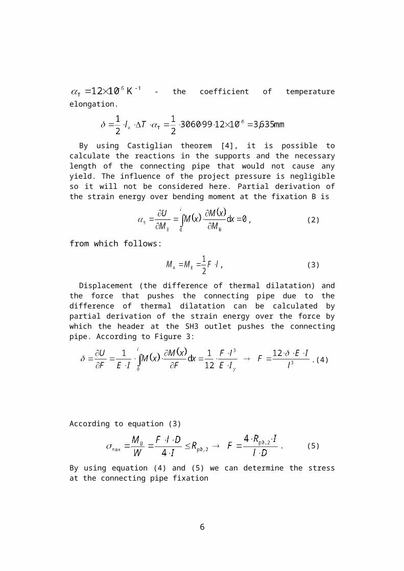
Figure 4: Stress / strain diagram for P235GHTC2 at 367 C [6]
The calculation was done in ANSYS 9.0. A bilinear model of the material was applied, with the use of tangent intersection (TI) method [7]. The boundary conditions and the finite element mesh are shown in Figure 5. 20-node isoparametric finite element SOLID95 with 3 degrees of freedom in each node was used for the model meshing [8].
Figure 5: Boundary conditions and a finite element mesh for the calculation and analysis of the connecting pipe SH3 with the same geometry as is presented in the Figure 3
6
Work pressure 48,6 bar
Pressure on the surface causing displacement
Fixation
Constrained displacement in the direction of z axis
Constrained displacement in the direction of x axis
x zy
The material yields at most for the 16 mm shifted cross section from the location of displacement acting, what is presented in the Figure 6. Yield zones are there almost symmetrical with portion which is more than 50%. The percent of the material yielding at the cross-section and maximum equivalent stress value according to the longitudinal axis of the pipe are depicted in the Figure 7.
Figure 6: The yield of material at the cross-section of the connecting pipe, x=16 mm
0
10
20
30
40
50
60
0 5 10 15 20 25 30
Cross-section position x, mm
Yie
ldin
g of
mat
eria
l thr
ough
cro
ss-s
ectio
n, %
169
170
171
172
173
174
175
176
177
178
179
180
Max
imum
of e
quiv
alen
t str
ess,
MPa
Yielding of material through cross-sectionMaximum of equivalent stress
Figure 7: The portion of the material yielding at the cross-section and maximum equivalent stress value according to the longitudinal axis of the pipe
7
5 Conclusion
According to the results of carried testing of the material at elevated temperatures, it can be concluded that material properties at work temperatures are much better than the available data from the reference books. This is good in terms of the carrying capacity of the structure.
Calculated value of difference of thermal dilatation of the membrane wall and the outlet header of SH3 was used for the FEM calculation, by using ANSYS 9.0. The magnitude of the yielding at the critical cross-section of connected pipe, with assumption of bilinear elastic-plastic material behaviour and according to the test data, was determined. The critical overflow pipe at the superheater 3 outlet, gave results, which guarantee that there will be no fracture, but under the assumption that the structure operates under normal (static) load.
Variable load due to the change of the membrane wall and superheater header temperature, and under the influence of work pressure variation, with eventual presence of the initial damage, can cause fracture. According to the Smith diagram, after the final number of the vibration load cycle (cold boiler start f.i.), there will be fracture because of the strain. The critical number of cycles is unknown at the moment because there are no Wöhler curves for the material which was used and the adequate work temperature.Because of the quiet structure load, and with specific way of load, which is present here, there will be some material relaxation, i.e. decrease of the maximal stress value.
References[1] http://www.aee-group.com/aee_dd/[2] Kozak, D. Sertić, J. Mechanical Engineering Faculty in Slavonski Brod. Institute for
mechanical engineering structures. Numerical investigation of elastic-plastic behaviour of connecting pipes between heat chamber and steam overheater loaded thermo-mechanically . Technical report (in Croatian). Slavonski Brod, February 2009.
[3] EN10216-2:2002+A2:2007 [4] Solecki, R. Jay Conant, R. Advanced Mechanics of Materials. Oxford University Press, New
York and Oxford, 2003.[5] Brnić, J. Elastomehanika i plastomehanika. Školska knjiga Zagreb, Zagreb, 1996.[6] Faculty of Engineering in Rijeka. Department of engineering mechanics. Experimental
determination of the mechanical properties of material at elevated temperature. Technical report (in Croatian), Rijeka, 04.02.2009
[7] Save, M. Experimental verification of plastic limit analysis of torispherical and toriconical head. In: (4th edn ed.), G. J. Bohm et al. Pressure Vessel and Piping: Design and Analysis 1, 382-416. ASME, 1972.
[8] ANSYS Release 9.0. Programme for finite element analysis
8