analysis of slotting models for the calculation of no-load rotor … · 2019-12-16 · analysis of...
TRANSCRIPT

Analysis of Slotting Models for the Calculation ofNo-Load Rotor Losses in PM Machines
J. R. Anglada, Student Member, IEEE, S. M. Sharkh, Senior Member, IEEE, and A. A. Qazalbash
Abstract—The magnetic flux density distribution in the air-gap of electric machines is essential for accurate prediction ofno-load eddy-current power losses. The effect of slotting canbe modelled using a simplified single-slot model or a completemultiple-slots model. Until now there has not been a clearand justified criterion to choose between the two models. Inthis paper we propose a criterion based on the conformaltransformations used to calculate the magnetic field distributionof single-slot and multiple-slots models. The computationalimplementation of both methods produced a graph that clearlyshows which method to use as a function of the normalisedgeometrical parameters of the machine. The paper presentsa case study of a high speed machine whose proportions fallwithin the multiple-slot model range, according to the criterionproposed. It is shown that using a single slot model in this caseresults in significant errors in the estimation of rotor losses.Better agreement with FEA results is achieved when a multiple-slot model is used.
Index Terms—Analytical models, permanent magnet ma-chines, conformal mapping, rotor eddy-current power losscalculation.
I. INTRODUCTION
ACCURATE calculation of the magnetic field in the air-gap of electric machines is essential when calculat-
ing rotor losses, cogging torque and similar quantities thatstrongly depend on the harmonic content of the magnetic fielddistribution [1]–[5]. High accuracy is crucial in the case ofrotor losses as small errors can result in designing a machinethat will run too hot if the losses are underestimated. Over-estimating the losses could result in a decision to abandon agood design variant and opting for expensive solutions suchas magnet segmentation or increasing the air-gap length orthe magnet and sleeve thickness.
The methods used to calculate the magnetic field in theair-gap of electric machines can be classified into two maingroups: numerical methods or analytical methods. Numericalmethods, like Finite Element Analysis (FEA), are extremelyuseful tools because they are versatile and accurate. However,the computation time tends to be high and in general it isdifficult to gain an insight from the these solutions unless
This work was supported by EPSRC and by TSL Technology.J. R. Anglada and S. M. Sharkh are with the Mechatronics Re-
search Group, Engineering Sciences, Faculty of Engineering and theEnvironment, University of Southampton, Highfield Campus, Southamp-ton SO17 1BJ, United Kingdom (e-mail: [email protected];[email protected]).
A. A. Qazalbash is with Emerson Control Techniques Dynamics Ltd, UK(email: [email protected]).
several geometries are analysed; some numerical solversprovide tools for parametric analysis for this purpose [6],[7]. Numerical methods remain very useful tools for thevalidation and the refinement of the final design.
On the other hand, analytical methods are still very usefultools for initial design and optimisation based on the insightobtained. Carter pioneered the use of conformal mapping,which transforms a slotted geometry of the air-gap into aslotless one in which the field could be calculated. He defineda coefficient to quantify the effect of slotting on the meanvalue of the magnetic field waveform [8]. However, thetransformation from the slotted geometry into the slotlessone is a Schwarz-Christoffel (SC) transformation that doesnot have an explicit expression for complicated domains [9]which made the practical application of this method difficult.Gibbs [10] extended Carter’s work by developing two dif-ferent methods also based on conformal mapping: one is asimplification considering infinitely wide teeth and the otherone takes into account the effect of the neighbouring slots.Freeman [11] applied Gibbs’ methods to a range of practicalgeometries and expressed the magnetic field distribution as aFourier series. Even though Gibbs’ method can be solved,the SC transformation of the multiple slots model is socomplicated that in most of the cases the single slot solutionis preferred [3]–[5], [12]–[14].
The problem of neglecting the effect of the neighbouringslots, i. e., using a single-slot model, is that when the teethare narrow and the air-gap is large the waveform obtainedmay not be of sufficient accuracy. This is commonly thecase in PM machines which have large effective air-gaps.In [3]–[5] for example, the machines analysed have verylarge effective air-gaps with thick magnets and sleeves. Inthese machines a strong influence from the adjacent slots isexpected and a multiple-slot model would be needed. But inthe literature only Freeman suggested a criterion to choosebetween single-slot and the multiple-slots models, but withoutany clear justification behind this assertion [11].
The aim of this paper is to understand the limitations ofthe single-slot model and develop a criterion that can be usedto determine when it is valid to apply it for the calculation ofrotor eddy-current power loss calculation. The methodologychosen for the analysis is Gibbs’ single-slot and multiple-slots methods because they are completely analytical and theassumptions of both models are exactly the same except forthe width of the teeth. For tooth widths that are higher thana certain value the influence of the adjacent slots can beneglected and the single-slot model is valid. For smaller tooth
widths there is an interaction between the neighbouring slotsand the single-slot model will be inaccurate. In theory themultiple-slots model should always provide correct resultsbut in practice for geometries with very large tooth widthsthe transformation is ill defined making the numerical solversfail to find a solution. In these cases the single-slot modelshould be used.
In this paper we propose a clear and explicit criterionfor choosing between single-slot and multiple-slots methods.This criterion is based on the properties of the confor-mal transformations proposed by Gibbs [10]. The graphicalrepresentation of the limits of application of each of themethodologies allows us to know immediately which modelto use in each case.
The paper starts with a summary of methodology tocalculate rotor eddy-current power loss calculation using acurrent sheet model. Then, Gibbs’ methodologies for thesingle-slot and multiple-slots geometries are presented briefly.Next, section IV shows how the limits of application of eachof the methodologies are obtained. The results are presentedin section IV-C; Fig. 5 covers the typical geometries andclearly states which model should be used in each case. Also,an example is presented to illustrate the significant errorsintroduced when neglecting the effect of the neighbouringslots in the calculation of rotor losses in a PM machine.Finally, the conclusions are presented in section VI.
II. CALCULATION OF NO-LOAD ROTOR EDDY-CURRENTPOWER LOSS
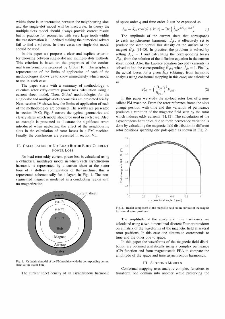
No-load rotor eddy-current power loss is calculated usinga cylindrical multilayer model in which each asynchronousharmonic is represented by a current sheet at the statorbore of a slotless configuration of the machine; this isrepresented schematically for 4 layers in Fig. 1. The non-segmented magnet is modelled as a conducting region withno magnetization.
µ1, σ1
µ2, σ2
µ3, σ3
µ4, σ4
Hub
Magnet
Air-gap
Stator
current sheet
Fig. 1. Cylindrical model of the PM machine with the corresponding currentsheet at the stator bore.
The current sheet density of an asynchronous harmonic
of space order q and time order k can be expressed as
Jqk = Jqk cos(qθ + kωt) = Re(Jqke
jqθejkωt). (1)
The amplitude of the current sheet that correspondsto each asynchronous harmonic, Jqk, is effectively set toproduce the same normal flux density on the surface of themagnet Bqk [3]–[5]. In practice, the problem is solved bysetting Jqk = 1 and calculating the corresponding lossesPqk1 from the solution of the diffusion equation in the currentsheet model. Also, the Laplace equation (no eddy currents) issolved to find the corresponding Bqk1 when Jqk = 1. Finally,the actual losses for a given Bqk (obtained from harmonicanalysis using conformal mapping in this case) are calculatedas
Pqk =( BqkBqk1
)2Pqk1. (2)
In this paper we study the no-load rotor loss of a non-salient PM machine. From the rotor reference frame the slotschange position with time and this variation of permeanceproduces a variation of the magnetic field seen by the rotorwhich induces eddy currents [1], [2]. The calculation of theasynchronous harmonics due to tooth permeance variation isdone by calculating the magnetic field distribution in differentrotor positions spanning one pole-pitch as shown in Fig. 2.
Fig. 2. Radial component of the magnetic field on the surface of the magnetfor several rotor positions.
The amplitude of the space and time harmonics arecalculated using a two-dimensional discrete Fourier transformon a matrix of the waveforms of the magnetic field at severalrotor positions. In this case one dimension corresponds totime and the other one to space.
In this paper the waveforms of the magnetic field distri-bution are obtained analytically using a complex permeance(CP) function and from magnetostatic FEA to compare theamplitude of the space and time asynchronous harmonics.
III. SLOTTING MODELS
Conformal mapping uses analytic complex functions totransform one domain into another while preserving the
angles [10]. Using conformal mapping we can transform adomain —a rectangular polygon in this case— into a newone in which the solution is known. If we call the originaldomain the z-plane and the new one the w-plane we canfind the relationship between their magnetic fields. For anarbitrary analytic complex function w = f(z) the expressionthat relates the magnetic field in both planes [13] is
Bz = Bw
(dwdz
)∗= Bw
(f ′(z)
)∗, (3)
where the asterisk denotes the complex conjugate. TheSchwarz-Christoffel (SC) transformation is commonly usedto find the suitable function f(z). By definition an SCtransformation can map the interior of an arbitrary polygonin the upper half of the complex plane [9].
The following methods based on [10], [11] show how toobtain the magnetic field distribution in the air-gap of electricmachines with a toothed member. The air-gap has a magneticpermeability of µ0 and the iron permeability is assumed tobe infinity.
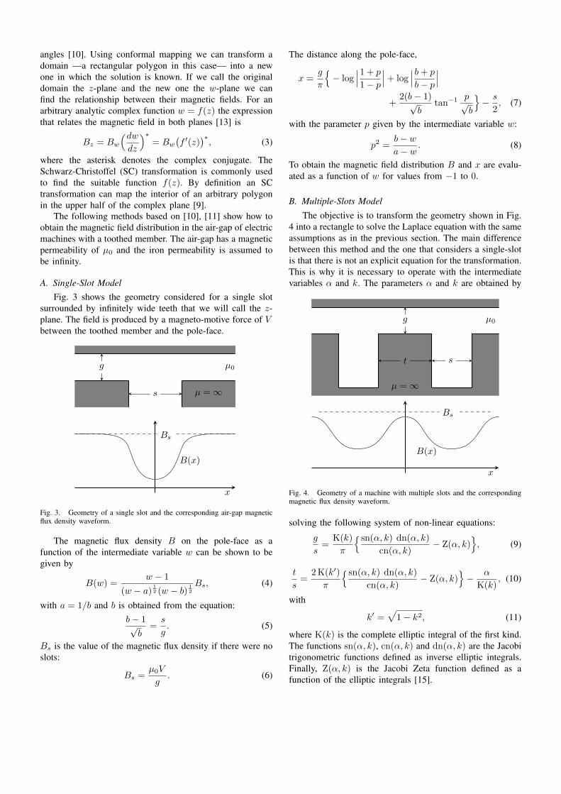
A. Single-Slot ModelFig. 3 shows the geometry considered for a single slot
surrounded by infinitely wide teeth that we will call the z-plane. The field is produced by a magneto-motive force of Vbetween the toothed member and the pole-face.
s
g µ0
µ =∞
Bs
x
B(x)
Fig. 3. Geometry of a single slot and the corresponding air-gap magneticflux density waveform.
The magnetic flux density B on the pole-face as afunction of the intermediate variable w can be shown to begiven by
B(w) =w − 1
(w − a)12 (w − b) 1
2
Bs, (4)
with a = 1/b and b is obtained from the equation:b− 1√b
=s
g. (5)
Bs is the value of the magnetic flux density if there were noslots:
Bs =µ0V
g. (6)
The distance along the pole-face,
x =g
π
{− log
∣∣∣1 + p
1− p
∣∣∣+ log∣∣∣b+ p
b− p
∣∣∣+
2(b− 1)√b
tan−1p√b
}− s
2, (7)
with the parameter p given by the intermediate variable w:
p2 =b− wa− w
. (8)
To obtain the magnetic field distribution B and x are evalu-ated as a function of w for values from −1 to 0.
B. Multiple-Slots Model
The objective is to transform the geometry shown in Fig.4 into a rectangle to solve the Laplace equation with the sameassumptions as in the previous section. The main differencebetween this method and the one that considers a single-slotis that there is not an explicit equation for the transformation.This is why it is necessary to operate with the intermediatevariables α and k. The parameters α and k are obtained by
µ0
µ =∞
t s
g
Bs
x
B(x)
Fig. 4. Geometry of a machine with multiple slots and the correspondingmagnetic flux density waveform.
solving the following system of non-linear equations:
g
s=
K(k)
π
{ sn(α, k) dn(α, k)
cn(α, k)− Z(α, k)
}, (9)
t
s=
2 K(k′)
π
{ sn(α, k) dn(α, k)
cn(α, k)− Z(α, k)
}− α
K(k), (10)
with
k′ =√
1− k2, (11)
where K(k) is the complete elliptic integral of the first kind.The functions sn(α, k), cn(α, k) and dn(α, k) are the Jacobitrigonometric functions defined as inverse elliptic integrals.Finally, Z(α, k) is the Jacobi Zeta function defined as afunction of the elliptic integrals [15].
The expression for the magnetic flux density as a functionof the intermediate variable v is:
B(v) =(1 + k21v
2)12
(1 + k2v2)12
Bmax, (12)
where
Bmax =πg
sK(k1)
cn(α, k)
sn(α, k) dn(α, k)Bs, (13)
with k1 = k sn(α, k).The distance along the pole-face,
x(v) =s
π
[{ sn(α, k) dn(α, k)
cn(α, k)− Z(α, k)
}β
+ tan−1−2∞∑1
(−1)mqm2
sin πmαK(k) sinh πmβ
K(k)
1 + 2∞∑1
(−1)mqm2 cos πmαK(k) cosh πmβK(k)
], (14)
with
β = F( v
(1 + v2)12
, k′), (15)
where F(φ, k) is the incomplete elliptic integral of the first
kind and q is called the nome, q = e−πK(k′)K(k) .
To obtain the flux density distribution B and x areevaluated as a function of v for values from 0 to ∞ in asimilar way as in the previous method.
IV. LIMITS OF APPLICATION
A. Practical Limit
When the teeth are wide enough it was noted by Gibbsand Freeman that the maximum value of the flux density,Bmax, is almost equal to Bs. This suggests that the effect ofneighbouring slots on the field distribution in the vicinity ofa slot is negligible.
We can define the following indicator to study if thesingle-slot model is going to give almost the same answeras the multiple-slots model for a particular geometry:
rp =BmaxBs
=πg
sK(k1)
cn(α, k)
sn(α, k) dn(α, k), (16)
where Bmax is obtained from (13). With this indicator for anygeometry (a given t/s and g/s) we can estimate immediatelyif both models give a similar answer. If the value of rp isclose to be 1 it means that the interaction between adjacentslots is negligible and a single-slot model can be used. If itis significantly smaller than 1 then a multiple-slot model isneeded.
B. Numerical Limit
This section shows the range of the geometrical variableswithin which the multiple-slots model is valid. Theoretically,according to the definition of the Schwarz-Christoffel trans-formation the geometry of Fig. 4 can always be mapped intoa rectangle. However, in practice when the ratio of the tooth
width t and the air-gap length g is large, i.e., the teeth arevery wide, the numerical solution of (9) and (10) becomesimpossible.
Let us define the right hand side of (9) as Fg(α, k) andthe right hand side of (10) as Ft(α, k):
g
s= Fg(α, k), (17)
t
s= Ft(α, k). (18)
Considering a particular value of gs = K, a curve ΓK of all
the points (α, k) that satisfy this equation can be defined asthe following:
(αi, ki) ∈ ΓK ⇔ Fg(αi, ki) = K. (19)
Of all the points in ΓK there is only one point (αopt, kopt)that satisfies:
Ft(αopt, kopt) =t
s. (20)
To know the limits of application of the multiple-slotsmethodology we need to find the maximum tooth widthwithin which the numerical solver can provide a solution.To find the maximum value of t
s for a particular value of gs
an algorithm was implemented in MATLAB. The algorithmis divided in three stages:
(a) Choose a value of gs = Fg(α, k) = K.
(b) Obtain the curve (family of points) ΓK .(c) Calculate the point (αopt, kopt) that maximizes the
function Ft(α, k) and evaluate ts |max.
The value of ts |max will depend on the numerical precision
of the software.For this case as the value of t
s increases k′ —see equation(11)— tends to be close to zero. This results in k being closeto 1 and the elliptic integral of the first kind has the followingproperty:
limk′→0
K(k′) =∞ ⇒ limk→1
Ft(α, k) =∞. (21)
For this reason the numerical limit in which the multiple slotsmethod has a solution will depend on the numerical precisionof the software; for the case of MATLAB the minimum valueof k′ in which K(k′) is not infinite is k′ = 10−8.
C. Representation of the Limits
This section presents the results obtained with MATLABafter implementing the algorithms to calculate the practicaland numerical limits. To obtain the limits the previousmethodology was applied for a range of values of g
s tocalculate the corresponding t
s |max.Freeman [11] proposed the following criterion: if t/g >
3.3 the single-slot model should be used and if t/g < 3.3the multiple-slots model should be used. This condition canalso be expressed using the normalised parameters t
s and gs :
t
s≶ 3.3
g
s. (22)

0 0.5 1 1.5 2 2.5 3
g/s
0
5
10
15
20
25
t/s
Numerical limit
Practical limit rp=99.99%
Practical limit rp=99.9%
Freeman‘s limit
Case study Both models
Single-slot model
Multiple-slots model
Fig. 5. Numerical and practical limits of the two methodologies as a function of the geometric variables. Also, representation of Freeman’s limit and theposition of the machine analysed in section V.
Fig. 5 shows the limit proposed by Freeman, the numer-ical limit and the practical limit for 3 different values of rpas a function of the normalised variables t
s and gs . The figure
can be divided in three different regions. In the region abovethe solid red line the single-slot model should always be usedbecause the multiple-slots model will fail as it was noted insection IV-B. Below the orange line with the circular markersignoring the effect of the neighbouring slots can producesignificant errors because the magnetic field in the middleof the teeth does not reach Bs as it was described in sectionIV-A (here the minimum value of rp was considered to be the99.9 %). Between these two lines both models can be used inthe sense that they will give similar answers. However, abovethe magenta line with square markers that is rp of 99.99 %the solution of both methods will be almost identical andk′ → 0. Freeman’s limit in Fig. 5 is the dashed blue line. Itis almost the same as the practical limit with rp of 99.9 %.
V. CASE STUDY
Fig. 6 shows a quarter of the cross-section of a high speedPM generator with a non-conductive rotor sleeve to hold themagnets, making the effective air-gap even larger [3]. Theparameters of this machine are shown in table I.
TABLE IPARAMETERS OF THE MACHINE
Quantity Symbol ValueNumber of poles 2p 4Number of slots Qs 24Core length L 125 mmRotor radius R1 21.6 mmMagnet outer radius R2 27.1 mmStator radius R3 31 mmMagnet thickness hm 5.5 mmSleeve thickness tsl 2 mmClearance gap hg 1.9 mmSlot opening bo 3 mmRotor hub permeability µr 750Rotor hub conductivity σr 6.7 · 106 S/mMagnet conductivity σm 0.77 · 106 S/mMagnet material - NdFeBMagnet remanence Br 1.07 TMagnet coercivity Hc 851 kA/m
Fig. 6. Quarter model of the PM synchronous generator under study.
Taking into account that the permeability of the magnetsand the sleeve is close to µ0 the effective air-gap length:
g = hm + tsl + hg = 9.4mm. (23)
In the developed model of the machine t = 3.492mm ands = 3.394mm, therefore
g
s≈ 2.770, (24)
t
s≈ 1.029. (25)
The position of this machine in Fig. 5 is shown with a blackcross. Clearly the machine is in the region where only themultiple-slots model should be used. To study the limitationsof the single-slot model the CP function is obtained for amultiple-slots and single-slot configuration for comparison.Both methodologies include a first conformal transformationto model the effect of curvature [16].
The no-load magnetic field distribution in the air-gap ofthe slotless configuration using the rotor’s reference frame
can be expressed using complex number notation as
Bsl(θ, r) =
∞∑n=1,3,5
Kn(r) cos(npθ)
+ j
∞∑n=1,3,5
Dn(r) sin(npθ), (26)
where the coefficients Kn(r) and Dn(r) are calculated ac-cording to [17] and j =
√−1 is the pure imaginary part.
The CP function (both for the multiple-slots and single-slotmodels) using the rotor’s reference frame is
λ(θ, r, t) = λa0 +
∞∑m=1,2,3
λam(r) cos(mQs(θ − ωt)
)+ j
∞∑m=1,2,3
λbm(r) sin(mQs(θ − ωt)
), (27)
where the coefficients λa0, λam(r) and λbm(r) are calculatedusing conformal mapping. Therefore, according to [13] themagnetic field distribution of the slotted geometry is
B(θ, r, t) = Bsl(θ, r) · λ∗(θ, r, t). (28)
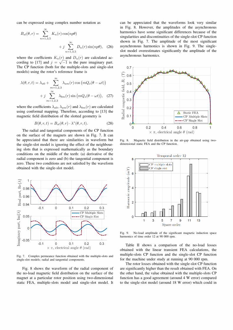
The radial and tangential components of the CP functionon the surface of the magnets are shown in Fig. 7. It canbe appreciated that there are similarities in waveform butthe single-slot model is ignoring the effect of the neighbour-ing slots that is expressed mathematically as the boundaryconditions on the middle of the teeth: (a) derivative of theradial component is zero and (b) the tangential component iszero. These two conditions are not satisfied by the waveformobtained with the single-slot model.
Fig. 7. Complex permeance function obtained with the multiple-slots andsingle-slot models; radial and tangential components.
Fig. 8 shows the waveform of the radial component ofthe no-load magnetic field distribution on the surface of themagnet at a particular rotor position using two-dimensionalstatic FEA, multiple-slots model and single-slot model. It
can be appreciated that the waveforms look very similarin Fig. 8. However, the amplitudes of the asynchronousharmonics have some significant differences because of thesingularities and discontinuities of the single-slot CP functionshown in Fig. 7. The amplitude of the most significantasynchronous harmonics is shown in Fig. 9. The single-slot model overestimates significantly the amplitude of theasynchronous harmonics.
Fig. 8. Magnetic field distribution in the air-gap obtained using two-dimensional static FEA and the CP function.
Fig. 9. No-load amplitude of the significant magnetic induction spaceharmonics of time order 12 at 90 000 rpm.
Table II shows a comparison of the no-load lossesobtained with the linear transient FEA calculations, themultiple-slots CP function and the single-slot CP functionfor the machine under study at running at 90 000 rpm.
The rotor losses obtained with the single-slot CP functionare significantly higher than the result obtained with FEA. Onthe other hand, the value obtained with the multiple-slots CPfunction has a good agreement (around 4 W error) comparedto the single-slot model (around 18 W error) which could in
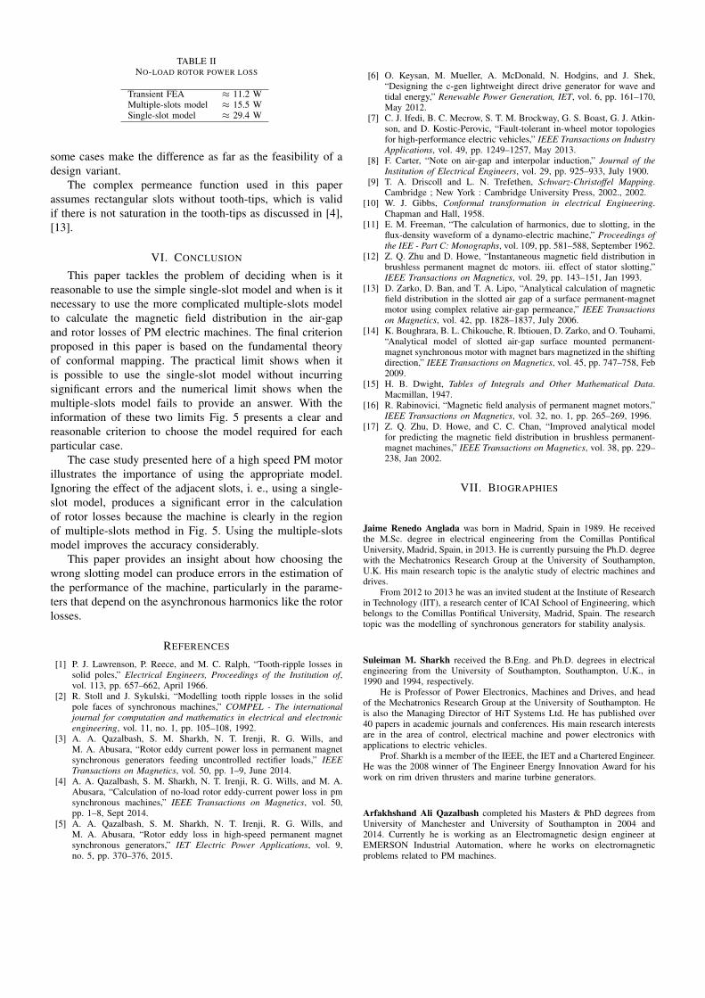
TABLE IINO-LOAD ROTOR POWER LOSS
Transient FEA ≈ 11.2 WMultiple-slots model ≈ 15.5 WSingle-slot model ≈ 29.4 W
some cases make the difference as far as the feasibility of adesign variant.
The complex permeance function used in this paperassumes rectangular slots without tooth-tips, which is validif there is not saturation in the tooth-tips as discussed in [4],[13].
VI. CONCLUSION
This paper tackles the problem of deciding when is itreasonable to use the simple single-slot model and when is itnecessary to use the more complicated multiple-slots modelto calculate the magnetic field distribution in the air-gapand rotor losses of PM electric machines. The final criterionproposed in this paper is based on the fundamental theoryof conformal mapping. The practical limit shows when itis possible to use the single-slot model without incurringsignificant errors and the numerical limit shows when themultiple-slots model fails to provide an answer. With theinformation of these two limits Fig. 5 presents a clear andreasonable criterion to choose the model required for eachparticular case.
The case study presented here of a high speed PM motorillustrates the importance of using the appropriate model.Ignoring the effect of the adjacent slots, i. e., using a single-slot model, produces a significant error in the calculationof rotor losses because the machine is clearly in the regionof multiple-slots method in Fig. 5. Using the multiple-slotsmodel improves the accuracy considerably.
This paper provides an insight about how choosing thewrong slotting model can produce errors in the estimation ofthe performance of the machine, particularly in the parame-ters that depend on the asynchronous harmonics like the rotorlosses.
REFERENCES
[1] P. J. Lawrenson, P. Reece, and M. C. Ralph, “Tooth-ripple losses insolid poles,” Electrical Engineers, Proceedings of the Institution of,vol. 113, pp. 657–662, April 1966.
[2] R. Stoll and J. Sykulski, “Modelling tooth ripple losses in the solidpole faces of synchronous machines,” COMPEL - The internationaljournal for computation and mathematics in electrical and electronicengineering, vol. 11, no. 1, pp. 105–108, 1992.
[3] A. A. Qazalbash, S. M. Sharkh, N. T. Irenji, R. G. Wills, andM. A. Abusara, “Rotor eddy current power loss in permanent magnetsynchronous generators feeding uncontrolled rectifier loads,” IEEETransactions on Magnetics, vol. 50, pp. 1–9, June 2014.
[4] A. A. Qazalbash, S. M. Sharkh, N. T. Irenji, R. G. Wills, and M. A.Abusara, “Calculation of no-load rotor eddy-current power loss in pmsynchronous machines,” IEEE Transactions on Magnetics, vol. 50,pp. 1–8, Sept 2014.
[5] A. A. Qazalbash, S. M. Sharkh, N. T. Irenji, R. G. Wills, andM. A. Abusara, “Rotor eddy loss in high-speed permanent magnetsynchronous generators,” IET Electric Power Applications, vol. 9,no. 5, pp. 370–376, 2015.
[6] O. Keysan, M. Mueller, A. McDonald, N. Hodgins, and J. Shek,“Designing the c-gen lightweight direct drive generator for wave andtidal energy,” Renewable Power Generation, IET, vol. 6, pp. 161–170,May 2012.
[7] C. J. Ifedi, B. C. Mecrow, S. T. M. Brockway, G. S. Boast, G. J. Atkin-son, and D. Kostic-Perovic, “Fault-tolerant in-wheel motor topologiesfor high-performance electric vehicles,” IEEE Transactions on IndustryApplications, vol. 49, pp. 1249–1257, May 2013.
[8] F. Carter, “Note on air-gap and interpolar induction,” Journal of theInstitution of Electrical Engineers, vol. 29, pp. 925–933, July 1900.
[9] T. A. Driscoll and L. N. Trefethen, Schwarz-Christoffel Mapping.Cambridge ; New York : Cambridge University Press, 2002., 2002.
[10] W. J. Gibbs, Conformal transformation in electrical Engineering.Chapman and Hall, 1958.
[11] E. M. Freeman, “The calculation of harmonics, due to slotting, in theflux-density waveform of a dynamo-electric machine,” Proceedings ofthe IEE - Part C: Monographs, vol. 109, pp. 581–588, September 1962.
[12] Z. Q. Zhu and D. Howe, “Instantaneous magnetic field distribution inbrushless permanent magnet dc motors. iii. effect of stator slotting,”IEEE Transactions on Magnetics, vol. 29, pp. 143–151, Jan 1993.
[13] D. Zarko, D. Ban, and T. A. Lipo, “Analytical calculation of magneticfield distribution in the slotted air gap of a surface permanent-magnetmotor using complex relative air-gap permeance,” IEEE Transactionson Magnetics, vol. 42, pp. 1828–1837, July 2006.
[14] K. Boughrara, B. L. Chikouche, R. Ibtiouen, D. Zarko, and O. Touhami,“Analytical model of slotted air-gap surface mounted permanent-magnet synchronous motor with magnet bars magnetized in the shiftingdirection,” IEEE Transactions on Magnetics, vol. 45, pp. 747–758, Feb2009.
[15] H. B. Dwight, Tables of Integrals and Other Mathematical Data.Macmillan, 1947.
[16] R. Rabinovici, “Magnetic field analysis of permanent magnet motors,”IEEE Transactions on Magnetics, vol. 32, no. 1, pp. 265–269, 1996.
[17] Z. Q. Zhu, D. Howe, and C. C. Chan, “Improved analytical modelfor predicting the magnetic field distribution in brushless permanent-magnet machines,” IEEE Transactions on Magnetics, vol. 38, pp. 229–238, Jan 2002.
VII. BIOGRAPHIES
Jaime Renedo Anglada was born in Madrid, Spain in 1989. He receivedthe M.Sc. degree in electrical engineering from the Comillas PontificalUniversity, Madrid, Spain, in 2013. He is currently pursuing the Ph.D. degreewith the Mechatronics Research Group at the University of Southampton,U.K. His main research topic is the analytic study of electric machines anddrives.
From 2012 to 2013 he was an invited student at the Institute of Researchin Technology (IIT), a research center of ICAI School of Engineering, whichbelongs to the Comillas Pontifical University, Madrid, Spain. The researchtopic was the modelling of synchronous generators for stability analysis.
Suleiman M. Sharkh received the B.Eng. and Ph.D. degrees in electricalengineering from the University of Southampton, Southampton, U.K., in1990 and 1994, respectively.
He is Professor of Power Electronics, Machines and Drives, and headof the Mechatronics Research Group at the University of Southampton. Heis also the Managing Director of HiT Systems Ltd. He has published over40 papers in academic journals and conferences. His main research interestsare in the area of control, electrical machine and power electronics withapplications to electric vehicles.
Prof. Sharkh is a member of the IEEE, the IET and a Chartered Engineer.He was the 2008 winner of The Engineer Energy Innovation Award for hiswork on rim driven thrusters and marine turbine generators.
Arfakhshand Ali Qazalbash completed his Masters & PhD degrees fromUniversity of Manchester and University of Southampton in 2004 and2014. Currently he is working as an Electromagnetic design engineer atEMERSON Industrial Automation, where he works on electromagneticproblems related to PM machines.