analog to digital conversion
TRANSCRIPT


Analog to Digital Conversion (ADC)

Analog-to-Digital Conversion
An analog signal is a continuous signal that contains time-varying quantities, such as temperature or speed, with infinite possible values in between
An analog signal can be used to measure changes in some physical phenomena such as light, sound, pressure, or temperature.
For example, an analog microphone can convert sound waves into an analog signal.
Even in digital devices, there is typically some analog component that is used to take in information from the external world, which will then get translated into digital form
(using an analog-to-digital converter).

Analog-to-Digital Conversion
A digital signal refers to an electrical signal that is converted into a pattern of bits. A digital signal has a discrete value at each sampling point. The precision of the signal is determined by how many samples are recorded per unit of time. For example an analog pattern (represented as the curve) alongside a digital pattern (represented as the discrete lines).
A digital signal is easily represented by a computer because each sample can be defined with a series of bits that are either in the state 1 (on) or 0 (off).
Digital signals can be compressed and can include additional information for error correction.

An analog-to-digital converter
Abbreviated ADC, A/D or A to D,A2D
ADC is a device that converts a continuous
quantity to a discrete digital number. The
reverse operation is performed by a digital-to-
analog converter (DAC).

©Alex Doboli 2006
Quantization
• Quantization is the process of converting the sampled continuous-
Valued signals into discrete-valued data
In mathematics and digital signal processing, is the process of mapping a large set of input values to a (countable) smaller set – such as rounding valuesto some unit of precision.

Quantizing
The number of possible states that the converter can output is:
N=2n
where n is the number of bits in the AD converter
Example: For a 3 bit A/D converter, N=23=8.
Analog quantization size:Q=(V max -V min)/N = (10V – 0V)/8 = 1.25V

Analog Digital Conversion
2-Step Process:
• Quantizing - breaking down analog value is a set of finite states
• Encoding - assigning a digital word or number to each state and matching it to the input signal

Step 1: Quantizing
Example:
You have 0-10V signals. Separate them into a set of discrete states with 1.25V increments. (How did we get 1.25V?
(Discussed in previous slide)
Output
States
Discrete Voltage
Ranges (V)
0 0.00-1.25
1 1.25-2.50
2 2.50-3.75
3 3.75-5.00
4 5.00-6.25
5 6.25-7.50
6 7.50-8.75
7 8.75-10.0

Step 2. Encoding
• Here we assign the digital value (binary number) to each state for the computer to read.
Output
States
Output Binary Equivalent
0 000
1 001
2 010
3 011
4 100
5 101
6 110
7 111

Sampling
• It is a process of taking a sufficient number of discrete values at point on a waveform that will define the shape of waveform.
• The more samples you take, the more accurately you will define the waveform.
• It converts analog signal into series of impulses, each representing amplitude of the signal at given point…….
3 Basic Types
• Flash ADC
• Digital-Ramp/Dual slope/Counter slope ADC
• Successive Approximation ADC

Flash ADC
• Flash ADC
• Also known as a Direct conversion ADC is a type of analog-to-digital converter that uses a linear voltage ladder with a comparator at each "rung" of the ladder to compare the input voltage to successive reference voltages.
How Flash Works
• As the analog input voltage exceeds the reference voltage at each comparator, the comparator outputs will sequentially saturate to a high state.
• The priority encoder generates a binary number based on the highest-order active input, ignoring all other active inputs.

3 bit Flash ADC Circuit

Flash ADC
• Very fast for high quality audio and video
• Very expensive for wide bits conversion
• Sample and hold circuit usually NOT required
• The number of comparators needed is 2n-1
which grows rapidly with the number of bits i.e. 4-bit,15 comparators; for 6-bit,63 comparators

Flash ADC
• Flash ADC is one of the fastest ADC
• Complexity is less when compared to other ADC’s
• As # bits increases we need more comparators so required more space on chip
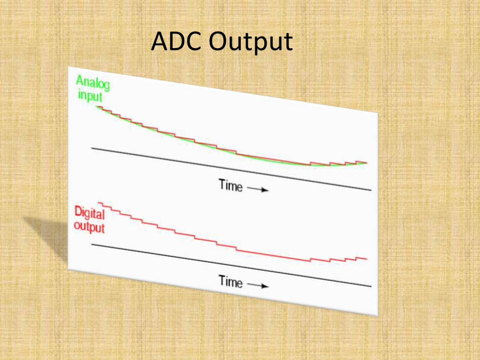
ADC Output

Flash
Advantages• Simplest in terms of
operational theory
• Most efficient in terms of speed, very fast
limited only in terms of comparator and gate propagation delays
Disadvantages
• Lower resolution
• Expensive
• For each additional output bit, the number of comparators is doubled
i.e. for 8 bits, 256 comparators needed

2-> Dual Slope ADC
• Also known as Counter-Ramp or Digital Ramp ADC
• A dual slope ADC is commonly used in measurement instruments (such as DVM’s).
ADC 1.21

Dual Slope ADC circuitInput
Digital Output
Oscillator
Control Logic
Registers
Switch
Counter
VReference
ADC 1.22

Dual Slope Function
• The Dual Slope ADC functions in this manner:– When an analog value is applied the capacitor begins to
charge in a linear manner and the oscillator passes to the counter.
– The counter continues to count until it reaches a predetermined value. Once this value is reached the count stops and the counter is reset. The control logic switches the input to the first comparator to a reference voltage, providing a discharge path for the capacitor.
– As the capacitor discharges the counter counts.
– When the capacitor voltage reaches the reference voltage the count stops and the value is stored in the register.
ADC 1.23

Successive approximation ADC
• Much faster than the digital ramp ADC because it uses digital logic to converge on the value closest to the input voltage.
• A comparator and a DAC are used in the process.

Successive Approximation ADC
• A Successive Approximation Register (SAR) is added to the circuit
• Instead of counting up in binary sequence, this register counts by trying all values of bits starting with the MSB and finishing at the LSB.
• The register monitors the comparators output to see if the binary count is greater or less than the analog signal input and adjusts the bits accordingly

Successive Approximation ADC Circuit
Output

Successive Approximation
Advantages
• Capable of high speed and reliable
• Medium accuracy compared to other ADC types
• Good tradeoff between speed and cost
• Capable of outputting the binary number in serial (one bit at a time) format.
Disadvantages
• Higher resolution successive approximation ADC’s will be slower
• Speed limited to ~5Msps
