an update on ccs: recent developments - cslf · an update on ccs: recent developments ... steam....
TRANSCRIPT

www.ieagreen.org.uk
An update on CCS: Recent developments An update on CCS: Recent developments
Harry AudusIEA Greenhouse Gas R&D Programme
Presented at:2nd IEA Workshop on Legal Aspects of storing CO2
Paris, France,17th October 2006

www.ieagreen.org.uk
CCS UPDATE: STRUCTURE OF PRESENTATION
1. Power generation - capture
2. CO2 Transport
3. Geological storage
4. near-term opportunities –route to commercial application

www.ieagreen.org.uk
CO2 CAPTURE

www.ieagreen.org.uk
Stationary sources of COStationary sources of CO22**
Power generation 4,942 (10.5 Gt)Cement production 1,175 (0.9 Gt)Refineries 638 (0.8 Gt)Petrochemicals 470 (0.4 Gt)Iron & Steel industry 269 (0.6 Gt)
* Of at least 100,000 tonnes/year. Figures from IPCC Special Report on Carbon Dioxide Capture and Storage

www.ieagreen.org.uk
Leading COLeading CO22 capture technologiescapture technologies• Capture of CO2 from flue gases:
• Post-combustion capture• Burning fuel in oxygen instead of air:
• Oxy-combustion• Conversion of fuel to H2 (and CO2) before
combustion:• Pre-combustion capture

www.ieagreen.org.uk
PostPost--combustion capture: processcombustion capture: process
Boiler or gas turbine
(FGD)
N2, O2, H2O to atmosphere
CapturePower generation
Air
Fuel Solvent scrubbing
PowerCO2 to storage
Steam
CO2compression
Steam turbine

www.ieagreen.org.uk
PostPost--combustion capture: solventcombustion capture: solvent• Widely used on reducing gases, e.g. natural gas• Less widely used for oxidising flue gases• MEA1 used in post-combustion capture plants
• CO2 is used in food & drink processing• New solvents being developed
• e.g. hindered amines• Lower energy consumption, solvent losses, <corrosion
• Low SOX (<10 ppm) and NO2 (<20ppm) is needed• Possible with limestone-gypsum FGD and SCR
1. MEA: mono-ethanolamine

www.ieagreen.org.uk
PostPost--combustion capture: statuscombustion capture: status
• Warrior Run power plant, USA
• 180 MWe coal fired circulating fluidised bed combustor
• 150 t/d of CO2 captured from a slipstream• About 5% of the total

www.ieagreen.org.uk
PostPost--combustion capture: KEY ISSUEScombustion capture: KEY ISSUES• Corrosion
• Stainless steel v carbon steel• Inhibitors can contain V, Sn, Sb (antimony)
• Solvent life• 2 US$/tCO2 (1,300 US$/t MEA and use of 1.6kg MEA/tCO2 )• Enhanced SO2 removal (10ppm to 2ppm ?)
• Environmental impacts• Some degradation products known and regulated others are
not.

www.ieagreen.org.uk
PostPost--Combustion capture: summaryCombustion capture: summary• Advantages
• Existing combustion technology can be used• Retrofit to existing plants is possible
• Retrofit to old inefficient plants is not attractive• Demonstrated at small power plants
• Disadvantages • Energy penalty has been relatively high
• Penalty is being reduced by process developments• Solvents are degraded by oxygen and impurities
• Environmental issues

www.ieagreen.org.uk
OxyOxy--combustion capture: processcombustion capture: processAir Air
separation
Fuel Boiler or gas turbine
Recycled flue gasVentOxygen
Purification/ compression
CO2Cooling (+FGD)
Power
Steam
Steam turbine

www.ieagreen.org.uk
OxyOxy--combustion capture: statuscombustion capture: status
5 MWe CES water cycle plant at Kimberlina, California

www.ieagreen.org.uk
OxyOxy--combustion capture: KEY ISSUEScombustion capture: KEY ISSUES
• Leak prevention & build up of inerts• Boiler under slight vacuum –pressurised operation
possible?• Wet recycle
• Acid corrosion implications• Purity of oxygen supply
• Inerts build up• Fate of impurities (SOx, NOx, etc.)

www.ieagreen.org.uk
OxyOxy--combustion capture: summarycombustion capture: summary• Advantages
• Combustors could be fairly conventional• Possibility of compact boilers with lower quantities of
flue gas recycle• Possibility of avoiding separate FGD step• Could give closest approach to ‘zero emissions’
• Disadvantages• Only tested at a small scale• High cost of oxygen production• If gas turbines, new designs are needed

www.ieagreen.org.uk
PrePre--combustion capture: process (noncombustion capture: process (non--gaseous fuel)gaseous fuel)
Coal Gasification Acid gas removal
Shift conversion
Air separation
Combined cycle
Air
Fuel gas (mainly H2)
Nitrogen
CO2CO2compression
Sulphur
Power
Oxygen
Air
H2S
Air
CO+H2O→H2+CO2
Sulphur recovery
IGCC

www.ieagreen.org.uk
PrePre--combustion status: IGCC without COcombustion status: IGCC without CO22 CaptureCapture
• 4 coal-based IGCC demonstration plants (USA, Netherlands, and Spain)
• Availability has been poor but is improving• IGCC is not, at present, the preferred
technology for new coal-fired power plants• At present the main commercial interest in
IGCC is for use of petroleum residues

www.ieagreen.org.uk
PrePre--combustion status: IGCC without COcombustion status: IGCC without CO22 capturecapture
Shell gasifier IGCC plant, Buggenum, Netherlands

www.ieagreen.org.uk
PrePre--combustion capture: KEY ISSUEScombustion capture: KEY ISSUES• Integrated operation
• Several processing units must all work• Turndown e.g. for load following
• Gasifier (or partial oxidation unit) availability• Maximum size• Spares requirement?• Burner and refractory life
• Hydrogen turbine• Can not used most advanced models

www.ieagreen.org.uk
PrePre--combustion capture: summarycombustion capture: summary• Advantages
• High CO2 concentration and high overall pressure• Lower energy consumption for CO2 separation• Compact equipment
• Proven CO2 separation technology can be used• Possibility of co-production of hydrogen
• Disadvantages• Unfamiliar technology for power generators• Coal-fired IGCC plants have had low availability• IGCC without CO2 capture has generally higher costs
than pulverised coal combustion

www.ieagreen.org.uk
COCO22 capture: summary capture: summary • CO2 can be captured using ‘existing’ technology
• 3 options to chose from• Capture technology needs to be demonstrated at
larger scales• CO2 capture reduces power plant efficiency by
about 6-11 percentage points• Cost of capture is about 1-3 US cents/kWh,
excluding storage ($20-60/t CO2-avoided)• Cost-reduction likely from ‘learning-by-doing’

www.ieagreen.org.uk
CO2 TRANSPORT

www.ieagreen.org.uk
COCO22 transmission: costs transmission: costs
0
5
10
15
20
25
30
35
40
45
50
0 500 1000 1500 2000 2500 3000 3500 4000 4500 5000
Distance (km)
Shi
p tra
nspo
rt co
sts
(US
$/tC
O2)
ship costs
offshore pipeline onshore pipeline

www.ieagreen.org.uk
Pipeline transmission: statusPipeline transmission: status
• CO2 pipeline transmission is well established• Large CO2 pipelines have been in use since the early
1970s• CO2 supplied for enhanced oil recovery• About 4000 km in use today• Most pipelines are in the USA (Texas/New Mexico)• Most of the CO2 is from natural sources• Individual pipeline capacities up to 20 Mt/y

www.ieagreen.org.uk
WeyburnWeyburn PipelinePipeline
• USA to Canada• CO2 from coal gasification
used for enhanced oil recovery • CO2 about 1% H2S and traces
of other sulphur compounds, including mercaptans• Good for detecting small leaks

www.ieagreen.org.uk
Shipping COShipping CO22 by tanker by tanker
• CO2 tankers:• CO2 transported as a
liquid (>6 bar, <-55C)• Construction similar to
LPG tankers• Attractive for long
distances• ‘Easier’ than shipping
LNG
CO2 tanker
LPG tanker

www.ieagreen.org.uk
COCO22 transport: summary transport: summary • CO2 pipeline transmission is well established• Existing pipelines have a good safety record• Ships can be attractive for long distance
transport• Costs <10$/tCO2 if the source is within 500km
of the store

www.ieagreen.org.uk
CO2 STORAGE

www.ieagreen.org.uk
COCO22 storage optionsstorage options
• Geological – covered in this presentation
• Ocean – unlikely to be environmentally acceptable in the near future
• Mineralisation – unlikely to be economically practicable in the near future
www.ieagreen.org.uk
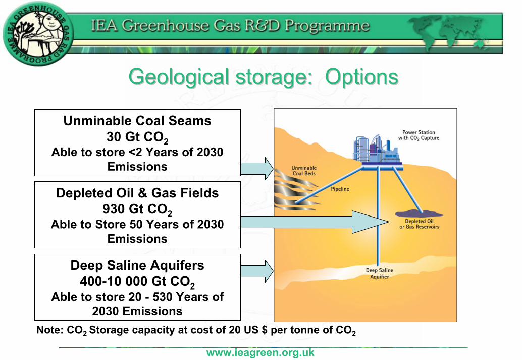
Geological storage: OptionsGeological storage: Options
Note: CO2 Storage capacity at cost of 20 US $ per tonne of CO2
Deep Saline Aquifers400-10 000 Gt CO2
Able to store 20 - 530 Years of 2030 Emissions
Depleted Oil & Gas Fields930 Gt CO2
Able to Store 50 Years of 2030Emissions
Unminable Coal Seams30 Gt CO2
Able to store <2 Years of 2030Emissions

www.ieagreen.org.uk
Geological StorageGeological Storage
• Sufficient capacity available to store all CO2 needed to stabilise emissions
• Will need to rely heavily on deep saline aquifers
• Need additional effort to quantify the storage capacity and integrity of deep saline aquifers

www.ieagreen.org.uk
Activities Underway on Capacity AssessmentActivities Underway on Capacity Assessment
Japan
Australia - Detailed assessment and risking analysis
APEC - Assessment of Pacific Rim Countries
UK - Southern North SeaChina - NZEP activity funded by ECActivity by USDOE
USA - Regional partnershipsEC - GESTCO/GEOCAPACITY (Central and Eastern Europe)
Canada - Alberta BasinIEA GHG - Northern Europe, North America, India
Basinal Level AssessmentsHigh Level Assessments
CSLF initiative to adopt a standard set of criteria for capacity assessment

www.ieagreen.org.uk
Costs of storage (US$/tCOCosts of storage (US$/tCO22))
0.5 – 4 173Depleted oil field
0.5 – 12.2123Depleted gas field
0.2 – 12122Saline aquifer
Range from IPCC SRCCS
IEA GHG results for North America
IEA GHG results for Europe
Storage formation

www.ieagreen.org.uk
Snøhvit
Sleipner
Weyburn
In-Salah
CommercialCommercial--scale operationsscale operations
Images Courtesy of BP, Statoil, and PTRC
NOT POWER GENERATION

www.ieagreen.org.uk
MonitoredMonitored COCO22 Stored UndergroundStored Underground
0
5
10
15
20
25
30
35
40
1995 1996 1997 1998 1999 2000 2001 2002 2003 2004 2005 2006 2007 2008 2009 2010Year
Milli
ons
of to
nnes
of C
O2
Sleipner (1996)
Weyburn (2000)
In Salah (2005)One 500MW coal-fired power station

www.ieagreen.org.uk
Current Status: COCurrent Status: CO22 storage activitystorage activity
Otway

www.ieagreen.org.uk
Deep Saline aquifersDeep Saline aquifers• Geology of oil and gas fields well known
• Demonstrated sealing potential• Punctured by many drilling holes
• Aquifers are largely unexplored structures• Many will be ‘virgin’ structures• Want to avoid them being punctured by wells to retain their integrity• Have to drill cores to ensure the caprocks will seal• Need extensive programme of geological and geophysical
characterisation before you can be sure they are suitable• Some parallels with natural gas storage industry

www.ieagreen.org.uk
Safety & PermanenceSafety & Permanence• Whenever CCS is discussed one of the key questions is
asked is:• Is it safe?
• Will the storage formations leak?• What are the environmental impacts if it leaks?
• This is a question we must answer satisfactorily• Important issue to resolve to get general acceptance for
this technology• Governmental commitment • Public awareness is low and could be a barrier to wide scale
implementation

www.ieagreen.org.uk
COCO22 ContainmentContainment• Statistics show there will be fugitive emissions from pipelines and surface
facilities• Low level and intermittent• Can quantify such emissions• Reported through national inventories
• The storage formation should be designed for zero seepage; but cannot say there will never be seepage incidents
• Preventative methods include:• Effective site characterisation
• Geology, hydrogeology, faults and wells• Risk assessment
• Health & Safety, short-term (project lifetime), long-term • Monitoring programme – pre and post injection• Remediation planning

www.ieagreen.org.uk
COCO22 ContainmentContainment• No evidence from any of the new large scale projects that
seepage is occurring.• One EOR project has reported surface seepage but there are
doubts about the data• Biogenically converted methane
• Performance assessment studies suggest negligible seepage• Weyburn – simulations suggest 5000 years before surface
seepage theoretically could occur• Sleipner modelling suggests all CO2 will have dissolved by
3000 years• No technical basis on which to quote a ‘seepage-rate’ for
geological storage

www.ieagreen.org.uk
Geological storage: summaryGeological storage: summary
• Demonstration of storage more advanced than demonstration of capture
• Confidence more of an issue than cost• Key issues:
• Permitting/Licensing • Long term liability• Environmental Impact Assessment• Monitoring requirements• Remediation practices

www.ieagreen.org.uk
The Route to wide-spread application of CCS

www.ieagreen.org.uk
The ChallengeThe Challenge
How do we get from where we are now(<10 ‘commercial-scale’ projects)
to wide-spread implementation with thousands of commercial CCS projects?

www.ieagreen.org.uk
A route to wideA route to wide--spread applicationspread application• Target for wide-spread application: Power generation – coal – deep saline aquifers
• Introduce the technology – using near-term opportunities• ‘cheap’ CO2• EOR• Financial instruments (Kyoto, CDM, JI, ETS)• Clear necessary ‘hurdles’ – involve legislators & regulators, H&SE issues (trials planned in UK),
acceptance
• Establish the technology- by demonstration and development• International co-operation & funding• Establishing a value-chain• Infrastructure use and development• Establish national & international legal & regulatory frameworks
• Apply the technology – through international action• Carbon management
• Allocation of responsibility for carbon between supplier and user• Supply security
• capture- ready power generation

www.ieagreen.org.uk
Creating a Creating a ‘‘ValueValue--chainchain’’
• Norwegian initiative to create a CO2 supply infrastructure• Part public sector/part private sector enterprise• Establish a CO2 supply infrastructure for Norway to
realise CO2 -EOR potential• Leave behind a supply infrastructure that can then
be used for CO2 storage

www.ieagreen.org.uk
Power SectorPower Sector• Power sector’s business is to produce and sell electricity • May prefer to act in the same way for CO2
• Pipelines and geological activities not traditional skills in power sector
• How do we establish a storage industry to work with the power sector?
• Will emissions trading be sufficient to establish such an industry?• CSS as a CDM option would be a good start

www.ieagreen.org.uk
Power Sector CCS ProjectsPower Sector CCS Projects
FutureGen Hypogen
ZeroGen
Sask Power RWE
BP DF2
BP DF1EoN
nZETVattenfall

www.ieagreen.org.uk
Examples of planned CCS projects Examples of planned CCS projects withwith power generationpower generation
• BP Miller-Peterhead DF1 project, UK• 475 MW natural gas fired power plant, pre-combustion capture• CO2 for EOR, Start up 2010
• BP Carson DF2 project, California• 500 MW petroleum coke gasification, pre-combustion capture• CO2 for EOR, Start-up 2011
• Shell/Statoil HALTEN project, Norway• 860 MW natural gas power plant, post-combustion capture• CO2 for EOR, Start-up 2011
• RWE project, Germany• 450 MW coal IGCC, pre-combustion capture• Saline reservoir storage of CO2, Start-up 2014
• Future Gen project, USA• 275 MW coal IGCC, pre-combustion capture• Saline reservoir storage of CO2, Start-up 2014

www.ieagreen.org.uk
Developing Country InvolvementDeveloping Country Involvement

www.ieagreen.org.uk
Developing Country ImplementationDeveloping Country Implementation• Route through the Kyoto Protocol to establish CCS
projects in developing countries is:• The Clean Development Mechanism (CDM)
• CCS inclusion as a CDM option was raised at COP11/MOP1 but a decision was deferred• Referred to UNFCCC Subsidiary Technical
Committee met in Bonn, Germany in May 2006• Referred back to COP12/MOP2 in November 2007
• Some resistance observed

www.ieagreen.org.uk
CONCLUSIONSCONCLUSIONS• The costs of CCS are not excessive and can be reduced by
application of the technology.• The main potential for cost-reduction is in the capture step.• Confidence in geological storage needs consolidating.• Demonstrations needed; particularly of capture at power
stations.• A ‘road-map’ to ‘wide-spread’ application is required.• It is important that ‘non-technical’ barriers are identified
early and resolved: financial, legal & regulatory, acceptance

www.ieagreen.org.uk
IEA GHG thanks you for your attentionIEA GHG thanks you for your attention