an introduction to plumbing and gas systems for … · an introduction to plumbing and gas ... 2.3...
TRANSCRIPT
PDHonline Course M352 (4 PDH)
An Introduction to Plumbing and GasSystems for Medical Facilities
2012
Instructor: J. Paul Guyer, P.E., R.A., Fellow ASCE, Fellow AEI
PDH Online | PDH Center5272 Meadow Estates Drive
Fairfax, VA 22030-6658Phone & Fax: 703-988-0088
www.PDHonline.orgwww.PDHcenter.com
An Approved Continuing Education Provider
www.PDHcenter.com PDH Course M352 www.PDHonline.org
© J. Paul Guyer 2009 Page 2 of 43
CONTENTS
1. GENERAL
1.1 PLUMBING SYSTEMS
1.2 WATERBORNE PATHOGEN PREVENTION/CONTROL
1.3 GENERAL DESIGN CONSIDERATIONS
2. POTABLE WATER SUPPLY SYSTEM
2.1 QUALITY 2.2 CONTINUITY OF SERVICE 2.3 BACKFLOW PREVENTION 2.4 DOMESTIC HOT WATER SYSTEMS
2.5 PLUMBING FIXTURES AND OTHER EQUIPMENT 2.6 SANITARY DRAINAGE SYSTEM 2.7 STORM WATER DISPOSAL
2.8 FUEL GAS SERVICE
2.9 MEDICAL GAS SYSTEMS
2.9.1 Systems for Medical Clinics
2.9.2 Dental Clinics
2.9.3 System Control Valves
2.9.4 Alarm Systems
2.9.5 Gas System Sources (Storage) 2.9.6 Point-of-Use Sources
2.9.7 Alternative Compressed Air Sources
2.9.8 Color Coding and Labeling
2.9.9 Medical Gas Systems Outlets 2.9.10 Emergency Power Source
2.9.11 Medical Compressed Air (MCA)
2.9.12 Dental Compressed Air (DCA) 2.9.13 Laboratory Air (LA) 2.9.14 Instrument Air (IA)
2.9.15 Surgical Handpiece Drive Air (SHDA)
www.PDHcenter.com PDH Course M352 www.PDHonline.org
© J. Paul Guyer 2009 Page 3 of 43
2.9.16 Medical-Surgical Vacuum System (MV)
2.9.17 Dental High Vacuum (DHV)
2.9.18 Dental Low Vacuum (DLV)
2.9.19 Central Dental High-Volume Laboratory Dust Evacuation (LDE)
2.9.20 Waste Anesthesia Gas Disposal (WAGD) 2.9.21 Oxygen (OX)
2.9.22 Nitrous Oxide (NO) 2.9.23 Nitrogen (NI) 2.9.24 Sterilization Gas
2.9.25 Process Gas
www.PDHcenter.com PDH Course M352 www.PDHonline.org
© J. Paul Guyer 2009 Page 4 of 43
An Introduction to Plumbing and Gas Systems for Medical Facilities J. Paul Guyer, P.E., R.A., Fellow ASCE, Fellow AEI
1. GENERAL.
This discussion provides an introduction to plumbing and medical gas systems for medical,
dental, training, and research facilities (hereinafter, Medical Treatment Facility). The
primary purpose of these systems is to provide safe and reliable support to the medical
mission. In addition, appropriate design consideration shall be given to ensure system
maintainability, economy and energy efficiency, and adaptability to future facility
modification or expansion.. This information is an introduction only to this topic. Designers
must always be guided in project design by current and applicable codes, standards and
practices.
1.1 PLUMBING SYSTEMS. Plumbing systems include domestic cold and hot water;
sanitary, storm, and industrial (acid) waste drainage; water treatment (such as softening,
deionization, reverse osmosis); fuel gas; and landscape irrigation. Plumbing systems shall
be designed to be safe reliable and maintainable. Selection of materials, equipment, and
installation techniques shall consider life cycle cost effectiveness and maintainability in
addition to medical functional requirements. Potable water distribution pipe 50 mm (2”) and
smaller shall be copper. Designers are specifically alerted to provide for appropriate system
isolation and balancability, and necessary equipment and design practices to avoid cross
connections and backflow.
1.2 WATERBORNE PATHOGEN PREVENTION/CONTROL. The Center for Disease
Control (CDC), the American Society of Heating, Refrigeration, and Air-Conditioning
Engineers (ASHRAE), the American Society for Healthcare Engineering (ASHE) and the
Joint Commission on Accreditation of Healthcare Organizations (JCAHO) have cited two
main means by which waterborne pathogens are introduced into medical treatment facilities
- by the water supply system and cooling towers. Water-borne bacteria, chiefly Legionella,
have been documented as the infectious pathogens in a significant percentage of
www.PDHcenter.com PDH Course M352 www.PDHonline.org
© J. Paul Guyer 2009 Page 5 of 43
nosocomial infections. The diseases associated with legionella infection are legionellosis,
frequently resulting in pneumonia, and Pontiac Fever, a less severe illness. The guidance
provided in this Section addresses control of Legionella in plumbing systems, and is based
in principle on the recommendations found in these references. Typical water supply
systems, including base or public central distribution and local wells, must be presumed to
be contaminated with the Legionella bacteria. Standard water utility treatment and testing
practices are not considered adequate to ensure protection against the bacteria entering a
facility. It is therefore necessary that Legionella bacteria prevention and control guidelines
be considered in Medical Treatment Facility designs.
1.2.1 Legionella Characteristics and Transmission. The legionella bacterium is found
throughout earth and water (aquifers, wells, reservoirs) environments, and must be
expected in all water supplies. The greatest danger to humans occurs when the organism is
permitted to multiply or “amplify” in a water supply system to the point that significant
numbers of bacteria are present. Factors that lead to amplification include the following:
• Growth support deposits or coatings in system piping or equipment (e.g. scale,
sediment, biofilm).
• A water temperature range of 25-42 degrees C (77-108degrees F) of both supply
domestic cold and hot water systems, including temperature at fixture discharge, hot
water generator, hot water return distribution systems, and in storage or holding
tanks,
• Stagnation in tanks, and supply and return distribution systems, for both cold and hot
water.
Legionella bacteria become aerosolized in moisture droplets of less than 5 micrometer
diameter (optimum transmission droplet size for sustained suspension in air), created by
shower heads, faucet aerators, spray nozzles, respiratory equipment, water impacting on
hard surfaces, and bubbles breaking (such as occurs in hydrotherapy bath whirlpools).
Practical means for altering the aerosols that can lead to legionella infections are limited.
www.PDHcenter.com PDH Course M352 www.PDHonline.org
© J. Paul Guyer 2009 Page 6 of 43
1.3 GENERAL DESIGN CONSIDERATIONS. Legionella protection guidance is provided
in applicable locations throughout this Section; however designers should also carefully
consider provisions in the latest editions of the guidelines referenced. Healthcare facility
operational procedures for legionella control, such as cleaning or decontaminating of
respiratory equipment and environmental sampling, are addressed in the referenced
guidelines. The referenced guidelines also address disinfection techniques for reducing
Legionella colonization in existing facilities, such as superheated water flushing and
hyperchlorination shocking. Generally speaking, the goal of the legionella-protection design
is not to eradicate the bacteria, but to prevent or limit colonization.
2. POTABLE WATER SUPPLY SYSTEM.
2.1 QUALITY. All potable water supplies shall have an established potability monitoring
program to be acceptable for use by an Medical Treatment Facility. When an Medical
Treatment Facility project includes a non-potable water service (i.e., “gray water”) for
systems such as irrigation, heating, or cooling, the design shall provide for requirements for
signage, pipe labeling, and other means as needed to clearly identify the system (including
outlets) as unsafe for human consumption.
2.2 CONTINUITY OF SERVICE. To the extent economically practicable, provide a
minimum of two water services for hospitals, with each service fed from separate mains and
sources, and designed for full demand (serving potable, process, and fire protection
systems). These services should enter the building at separate locations. The purpose of
this provision is to provide an uninterrupted supply of potable water, or permit swift service
restoration, in the event of a water main break. If two separate water sources are not
practically available, on-site storage shall be considered. Where practical, loop the mains
around the facility and provide sectionalizing valves.
2.3 BACKFLOW PREVENTION. The flow of non-potable water, or any other nonpotable
liquids, into the potable water supply shall be prevented. Necessary measures to prevent
backflow, cross connection, or back-siphonage shall be included in the design. Cross
connection of a municipal and installation-dedicated (well-based, base pumping station,

www.PDHcenter.com PDH Course M352 www.PDHonline.org
© J. Paul Guyer 2009 Page 7 of 43
etc.) system shall require approval from the local Administrative Authorities. Generally,
backflow isolation will be required on the main supply mains serving a Medical Treatment
Facility; Designers shall coordinate backflow prevention requirements, including
requirements for maintenance accessibility and periodic testing, with the local municipality,
as appropriate.
2.3.1 Devices and Methods. All potable water discharge points, such as a faucet
discharging into a reservoir sink or tub, shall be provided with an adequate air gap, in
accordance with referenced criteria. Fixtures or equipment where the discharge point is
positioned below the reservoir rim shall be fitted with a vacuum breaker. Examples of
concern include the following:
• Bedpan washers, or similar fixtures including a flushometer valve.
• Flexible-hoses or shower heads, of length sufficient to reach below fixture rim,
typically found in procedure rooms, hydrotherapy bath equipment, laboratories, and
food service areas (e.g. washers, steam tables).
• Laboratory or other serrated-nozzle fixtures designed to accept flexible tubing.
• Water delivery outlets serving therapeutic, surgical, or autopsy/mortuary procedures.
• Hose bibs.
For the protection of makeup supplies to low hazard equipment (such as autoclaves and fire
protection sprinkler systems), double-check backflow preventers may suffice. For the
protection of sources supplying high hazard equipment and processes, reduced-pressure
backflow preventers are required. Designers shall include provisions for drainage of the
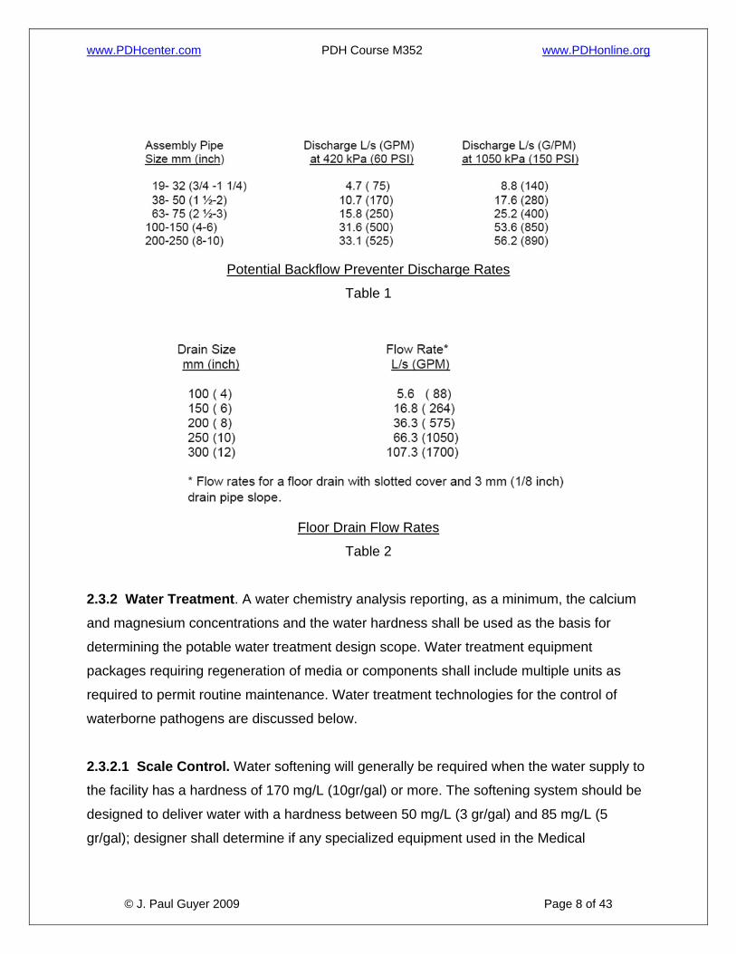
discharge from these devices; refer to Tables 1 and 2.
www.PDHcenter.com PDH Course M352 www.PDHonline.org
© J. Paul Guyer 2009 Page 8 of 43
Potential Backflow Preventer Discharge Rates
Table 1
Floor Drain Flow Rates
Table 2
2.3.2 Water Treatment. A water chemistry analysis reporting, as a minimum, the calcium
and magnesium concentrations and the water hardness shall be used as the basis for
determining the potable water treatment design scope. Water treatment equipment
packages requiring regeneration of media or components shall include multiple units as
required to permit routine maintenance. Water treatment technologies for the control of
waterborne pathogens are discussed below.
2.3.2.1 Scale Control. Water softening will generally be required when the water supply to
the facility has a hardness of 170 mg/L (10gr/gal) or more. The softening system should be
designed to deliver water with a hardness between 50 mg/L (3 gr/gal) and 85 mg/L (5
gr/gal); designer shall determine if any specialized equipment used in the Medical
www.PDHcenter.com PDH Course M352 www.PDHonline.org
© J. Paul Guyer 2009 Page 9 of 43
Treatment Facility may require more stringent requirements. Dental facilities’ water
hardness shall not exceed 85 mg/L.
2.3.2.2 High Purity Water Systems. Water purification is the process by which
contaminants or impurities, which affect undesirably the performance of specific equipment,
or the outcome of medical and laboratory tests, are removed from the water. Water
purification systems include reverse osmosis, deionization, ultra filtration, and UV
sterilization. Type I and Type III reagent grade water, as specified in ASTM D 1193
(reference 8g), are used in various applications such as for medicine preparation processes
in pharmacies, in distillation units, for designated laboratory outlets, and in selected
equipment for Renal Dialysis, Glassware Washing, Central Sterile Supply, and other
medical and laboratory functions. Their use shall be coordinated with the Using Agency and
the Government Design Agent. The designer shall consider local and central treatment
options, and treatment system combinations, best meeting the User’s needs and overall life
cycle cost.
2.3.3 Legionella Control. The relative danger that legionellae pose in any given Medical
Treatment Facility is a function of “system” factors which promote or discourage
colonization of the relative vulnerability of the patient population, and even of such factors
as climate and ground water temperature. The presence of aerosol generating sources
such as showers and whirlpool baths increase the risk of legionella infection. More seriously
ill patients, particularly those who are immunocompromised by medical condition or
treatment, are more vulnerable to legionella infection than the general population. In
addition to potential contamination danger from hot water systems, cold water systems pose
the risk of supporting legionella colonization if the piping systems are subjected to heat
sources. The temperature of cold water systems may be elevated into ranges more
conducive to legionella colonization by ground temperatures, piping located in attics, ceiling
spaces, equipment rooms, crawlspaces, or other unconditioned spaces, or by being located
adjacent to hot water or steam piping. All of these risk factors should be taken into
consideration when designing the domestic water system to help determine what special
measures, if any, are called for to help control legionella.
www.PDHcenter.com PDH Course M352 www.PDHonline.org
© J. Paul Guyer 2009 Page 10 of 43
2.3.3.1 Scale, Sediment, and Biofilm. Scale, sediment, and biofilm are contaminants that
support Legionella bacteria colonization. The extent to which these support colonization is a
function of factors including potable water service quality (including the presence of living
aquatic amoebae such as are found in biofilms), system operating temperatures, and pipe
material. Standard control technologies for scale and sediment deposits normally minimize
the contribution of these factors to legionella colonization. Biofilms are resistant to some
treatments. For addition and alteration projects, designers must be aware of the potential
presence of established biofilms, sediments, and scale. Exercise caution in reusing existing
piping system components without an analysis of the existing conditions. It may be
contributing to Legionella colonization and subsequently, may lead to contamination of new
service.
2.3.3.2 Reducing Legionella Potential in Existing Facilities. High velocity water flushing
may be to some degree effective to purge excessive scale and sediment from existing
piping or equipment. Additional measures for reducing legionella colonization potential
include cleaning or replacement of hot-water storage tanks, hot water generators, faucets,
and showerheads. Piping disinfection may be accomplished via hyper chlorination at levels
of up to 10 mg/L of free residual chlorine, or by thermal shock (hot water flushing) using
water heated to a temperature of 65 degrees C (150 degrees F) or more for a duration of at
least 5 minutes.
2.3.3.3 Design Considerations. Treatment systems for legionella control shall be sized on
the total potable water demand – both cold and hot. Treatment shall be applied to the water
service main. Designs should incorporate the following practices to minimize the potential
for legionella colonization:
• Treatment systems shall be provided for hospitals, and shall be either copper-silver
ionization or chlorine dioxide.
• Whenever practicable, specify pipe, equipment, and fixture components having
direct water contact to be of materials which inhibit bacteria colonization, such as
www.PDHcenter.com PDH Course M352 www.PDHonline.org
© J. Paul Guyer 2009 Page 11 of 43
copper. For inpatient Medical Treatment Facilities, avoid materials that support
colonization, such as natural rubbers and some plastics, whenever practical.
• Design distribution mains to maintain balanced flow throughout. Piping runs should
be as short as practicable. Avoid creating piping “zones” which experience
infrequent use, and therefore stagnation. As practicable, route mains close to
fixtures to minimize the lengths of branch piping runs. Avoid creating stagnant piping
sections, e.g. dead legs. Do not locate cold water piping near hot water piping or
other heat sources.
• Locate pressure balancing and thermostatic mixing anti-scald valves as close as
practicable to the fixture discharge. The maximum pipe run should be 2 meters (6
feet).
• Piping between fixture shutoff and discharge should be self-draining where possible.
• Use care to properly select the operating head of the recirculation pump(s), taking
into consideration system head requirements, including the pressure drop of
thermostatic mixing valves.
• Consider instantaneous hot water generators where feasible, and when on-site
storage is not required by other criteria, to avoid stagnant storage conditions.
• Water storage of holding tanks, both cold and hot, shall be designed to have
continuous flow with maximum practical velocity. They shall not be piped as
branched components with discharge line shutoff valves closed. Storage tank
capacity shall be adequate for the application, but not oversized. The capacity sizing
shall factor in the current healthcare procedures such as increased outpatient
medical functions reducing the load profiles and hot water recovery demand.
www.PDHcenter.com PDH Course M352 www.PDHonline.org
© J. Paul Guyer 2009 Page 12 of 43
2.4 DOMESTIC HOT WATER SYSTEMS.
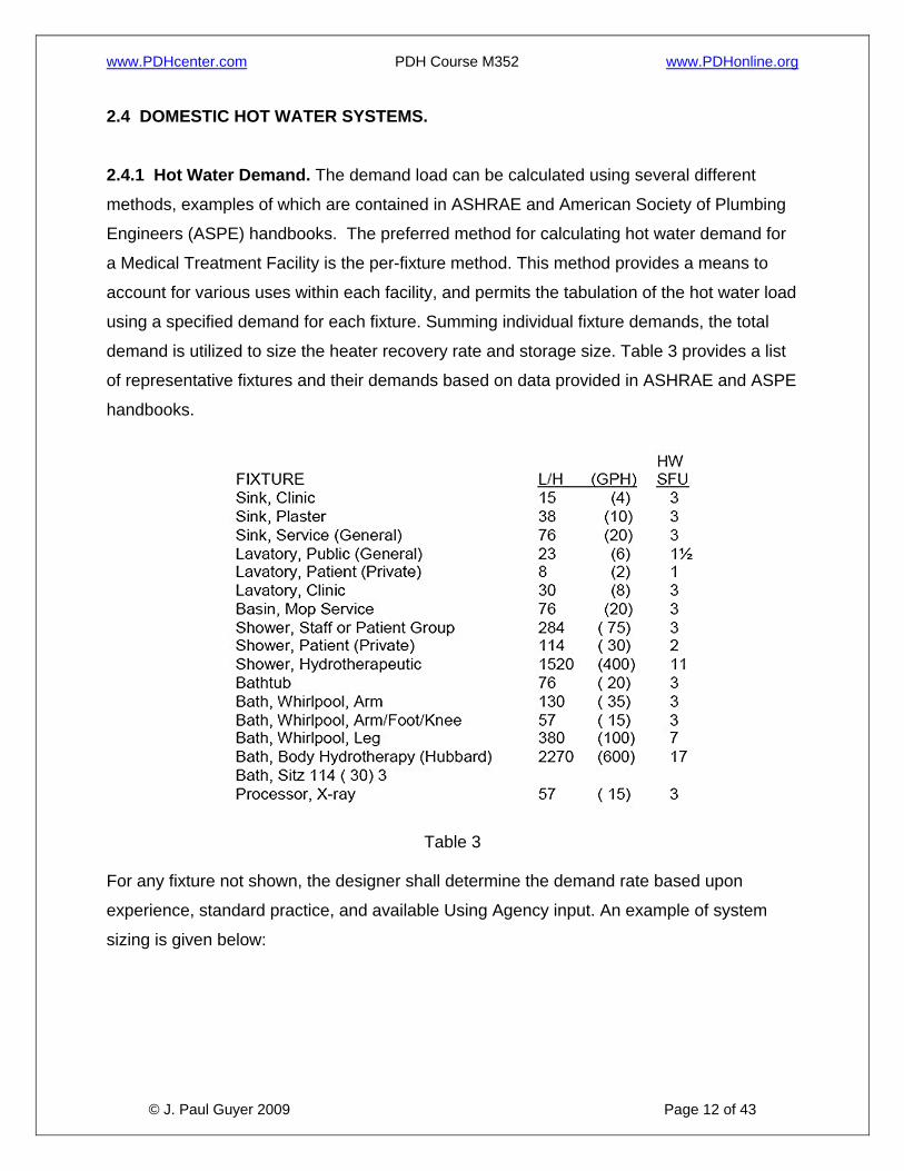
2.4.1 Hot Water Demand. The demand load can be calculated using several different
methods, examples of which are contained in ASHRAE and American Society of Plumbing
Engineers (ASPE) handbooks. The preferred method for calculating hot water demand for
a Medical Treatment Facility is the per-fixture method. This method provides a means to
account for various uses within each facility, and permits the tabulation of the hot water load
using a specified demand for each fixture. Summing individual fixture demands, the total
demand is utilized to size the heater recovery rate and storage size. Table 3 provides a list
of representative fixtures and their demands based on data provided in ASHRAE and ASPE
handbooks.
Table 3
For any fixture not shown, the designer shall determine the demand rate based upon
experience, standard practice, and available Using Agency input. An example of system
sizing is given below:

www.PDHcenter.com PDH Course M352 www.PDHonline.org
© J. Paul Guyer 2009 Page 13 of 43
Explanation of Example 1: A Demand Factor is applied to the Possible Maximum Demand to calculate
the Probable Maximum Demand. The Probable Maximum Demand is the rate
at which the heater shall generate hot water, or the recovery rate.
The Probable Maximum Demand is factored by the Storage Capacity Factor to
determine the Storage Tank Capacity. The Storage Tank Capacity is the
capacity required being available for use. Storage tanks are not considered to
be 100% usable and thus, a usable storage tank factor shall be applied to the
calculated storage tank capacity; the percent capacity considered usable for
most tanks is 70, thereby resulting is a 1.43usable storage tank factor. The
usable storage tank factor for systems utilizing instantaneous generators or
multiple tank arrangements shall be coordinated with the Design Agent.
Additional Note: The fixture-unit method is adequate for typical usage.
Expanded usage for food service, non-standard fixtures, or abnormal usage
patterns (extreme low or high demand peaks or erratic peak duration and
www.PDHcenter.com PDH Course M352 www.PDHonline.org
© J. Paul Guyer 2009 Page 14 of 43
occurrence) shall be factored into the sizing calculations. For example, food-
service fixture demand factors need to be adjusted if disposable service ware
is used. Concentrated patient treatment for sick call, or other instance of high-
peak usage, is another example of fixture hot water demand adjustment.
The Demand Factor and Storage Capacity Factor are listed in References 8h
and 8i for given building types, which include a hospital but not medical clinic,
dental clinic, nor laboratory. A Demand Factor of 0.40 and Storage Capacity
Factor of 1.00 are considered representative for a clinic upon review of the
factors for the building types shown. Factors for Medical Treatment Facilities
with laboratory space greater than 10% of the total facility space shall be
coordinated with the user.
2.4.2 Hot Water Design Temperature. Domestic hot water shall be generated and stored
at 60 degrees C (140 degrees F) minimum. It shall be tempered with a thermostatic mixing
valve at the hot water generator discharge to permit distribution at a temperature range
between 43 and 52degrees C (110-126 degrees F). The maximum hot water temperature
distribution design set point shall be 43 degrees C (110 degrees F).However, provide the
capability to increase system temperature to 52degrees C (126 degrees F) to permit a
Medical Treatment Facility the option to increase the temperature if so recommended by the
Infection Control Officer. It is extremely important to note that at this temperature the
exposure time for a first-degree burn is approximately 45 seconds. This is considered an
adequate period for a fully aware adult to remove the exposed body area from the stream of
a sink or lavatory, thereby maintaining a relatively safe condition at these fixtures without
the requirement furan anti-scald valve. Infants, persons desensitized by medical condition
or treatment, or those with severely limited motor capabilities, may be endangered by water
at this temperature. Anti-scald valves shall be provided as close as possible to the taps of
“whole-body” fixtures such as showers, bathtubs, and hydrotherapy baths. Hot water
recirculation systems shall be designed to limit system temperature drop to 3 degrees C
(5.5 degrees F) or less. Maximum hot water temperatures for other applications shall not
exceed the following:
www.PDHcenter.com PDH Course M352 www.PDHonline.org
© J. Paul Guyer 2009 Page 15 of 43
• Supply and Utility Areas. Central sterile supply, soiled utility rooms equipped with
bedpan washers, cart wash areas, and special pathological wash areas shall be
provided with 60 degrees C (140 degrees F) hot water.
• Kitchen Areas. The temperature normally required in dietary areas is the same as
that distributed to standard hand washing and bathing plumbing fixtures.
Dishwashing (automatic equipment) and pot washing normally require 82 degrees C
(180 degrees F). Booster heaters shall be provided to obtain this temperature.
• All Other. All other domestic hot water applications shall be provided with a hot water
temperature the same as is distributed to standard hand washing and bathing
fixtures.
2.4.3 Hot Water System Temperature Maintenance. In most facilities, a means of
controlling system heat loss (and therefore temperature decrease) will be required to
maintain delivery temperatures within acceptable tolerances. Hot water recirculation is
required for all patient care facilities (both inpatient and outpatient), and shall be located as
close to the fixture connections as practicable. Designs shall include provisions for isolating
and balancing the system. Heat tape systems may be utilized in non-patient care facilities if
cost justified, but are considered less desirable due to reported system malfunctions and
difficulty in locating the malfunction point.
2.5 PLUMBING FIXTURES AND OTHER EQUIPMENT. Plumbing fixtures should conform
generally to American Society of Mechanical Engineers International, ASME standards
series A112 or International Association of Plumbing and Mechanical Officials, IAMPO
standards seriesZ124.
2.5.1 Handicapped Fixtures. Provide handicapped fixtures in accordance with the
requirements of the Accessibility Provisions for the Disabled Section of this document and
the TMA PFD.
www.PDHcenter.com PDH Course M352 www.PDHonline.org
© J. Paul Guyer 2009 Page 16 of 43
2.5.2 Drinking Water Coolers. Locate public drinking water coolers convenient to each
public waiting room and elsewhere as directed. The standard rating and performance shall
conform to ARI Standard 1010 (reference 8m). Refer to the Accessibility Section of this
document for handicapped requirements.
2.5.3 Emergency Shower/Eye Wash Fixtures. Design in accordance with the American
National Standards Institute (ANSI) Standard Z358.1.
2.5.4 Water Usage Conservation. As of July 1992, the National Energy Policy Act
(EPACT) has specified maximum consumption requirements for water closets, urinals,
faucets and shower heads (for example, the water closet standard was lowered from 13.2
liters (3.5 gallons) per flush to 6.1 liters (1.6 gallons). Low-flow fixtures shall be specified for
all projects.
2.6 SANITARY DRAINAGE SYSTEM. The Medical Treatment Facility sanitary waste
system shall be connected to an approved existing sewer system, either government or
private as appropriate. If an existing sewage disposal system is not available, an approved
alternative system shall be provided. For example, a holding tank may be acceptable for
remote locations, for temporary service while awaiting the installation or retrofit of an
approved sewage disposal system, or a backup such as for hardened or essential facilities.
Any alternative to an approved central sanitary system shall be coordinated with the
Installation’s local approving authority. When connected to a local public system, code
requirements in excess of the IPC (reference 8b) imposed by the local regulatory agencies
shall be considered in the design. The system shall be designed to avoid excessive back
pressure and aspiration effects. Adequate cleanouts shall be provided to permit access to
all sections of the waste drainage system. The cleanouts shall be located to avoid or
minimize disruption of medical functions. If a facility sanitary waste requires lifting or
pumping, provide duplex pumping equipment and a backflow preventing check valve. This
equipment shall be connected to the alternative power source if one exists, or is included in
the project scope.
2.6.1 Protection of Special Fixtures and Equipment. Fixtures and equipment used for
sterilization, and food preparation, processing, or storage, shall be protected from
www.PDHcenter.com PDH Course M352 www.PDHonline.org
© J. Paul Guyer 2009 Page 17 of 43
contamination by backflow of waste. An indirect waste line, such as an air break or physical
disconnection (open drain) at the associated waste outlet, shall be incorporated into the
system design. These provisions also apply to equipment that cannot be easily cleaned.
Included are sterilizers, glass washers, refrigerators, kitchen equipment, film X-ray
processors, dental lab equipment (e.g. boilout assembly tanks), and vacuum system
separator tanks.
2.6.2 Special Drainage Equipment. Interceptors shall be provided when precious
materials or heavy metals, such as silver and barium, are sediment in the waste drainage
from such spaces as a Cast Room, a Prosthodontics Laboratory, barium procedure areas,
film X-ray processing, and spaces employing blood analyzers. Interceptors for barium waste
shall be aluminum. Flush rim floor drains shall be provided in Autopsy. Garbage grinding
disposers shall be provided in kitchens on dishwashers, pot and pan sinks, and other sinks
as designated. Grease traps shall be provided with grease-producing kitchen equipment
including prewash sinks, pot washers or sinks, and floor drains serving kettles. Separators
shall be provided in uses where petroleum products are subject to dripping or spills, such as
ambulance garages and mechanical equipment rooms.
2.6.3 Special Purpose Waste Lines. Separate waste lines shall be provided for acid
waste and radioactive waste from laboratories, darkrooms and nuclear medicine treatment
rooms, when justified by the quantities and/or concentration of reagent expected to be
introduced. Acid-resistant waste piping will be utilized for such applications and, if required,
will pass through a neutralizing or dilution tank before combining with building waste. If large
quantities of acid or strong base solutions are to be discharged into the waste system,
neutralization will be required. There are various radioactive materials to be found in a
Medical Treatment Facility. The particular radioactive waste for a given facility shall be
identified. The appropriate prescribed manner of disposal in accordance with federal and
local safety standards shall be incorporated into the design.
2.6.4 General-Purpose Floor Drains. General floor drains shall be considered for rooms
in which water-using plumbing fixtures or equipment are located. These include physical
therapy rooms which are equipped with hydrotherapy equipment, central sterile areas for
www.PDHcenter.com PDH Course M352 www.PDHonline.org
© J. Paul Guyer 2009 Page 18 of 43
sterilizers and sanitizing washers, food service areas, wash-down and housekeeping. Floor
drains are normally not required at emergency shower locations.
2.6.5 Trap Priming. Where a trap seal is subject to loss by evaporation, a trap seal primer
valve shall be installed per IPC. When utilized, automatic primers shall incorporate a
backflow prevention feature. Other means of trap prime maintenance, such as using
alternative sealing fluids (e.g. glycerin), are not permitted.
2.6.6 Retrofit/Alteration Considerations. The replacement of older existing fixtures with
lower-flow fixtures will alter system performance. Smaller diameter pipe or increased slope
may be necessary alterations.
2.6.7 Elevator Pit Sumps. Elevator pits shall be provided with a sump, which shall be
either pumped or drained by gravity. Pumped designs shall deliver fluids to an indirect
connection to the sanitary or storm drainage systems, such as a floor drain. The sump
discharge line shall include a check valve to prevent back flow of fluid into the sump. If
permitted by the local jurisdiction, a direct connection to the storm drainage system may be
considered. Designers should also determine from the base engineering office or local
jurisdiction if an oil interceptor is required. No other drains or sump discharges shall be
connected to the elevator pit drain or sump. This equipment shall be connected to the
alternative power source if one exists or is included in the project scope.
2.6.8 Mercury Control. Facilities containing operations which generate mercury wastes in
the free or leachable (e.g. dental filling amalgams) state which are intended to be disposed
to the sanitary waste system, shall consider separation provisions in accordance with
federal, state or local requirements. The separation provision shall be incorporated as close
to the source point as feasible. For mercury generating operations which do not require a
separation provision initially, provide a 0.2 square meter (2 square foot) floor space with
0.67 meter (2 foot) clearance all around to accommodate a retrofit installation.
2.7 STORM WATER DISPOSAL. Provide drainage and disposal of storm water, direct or
from runoff, from roofs and paved areas. The means of disposal shall preferably be to an
existing storm sewer. If an existing storm sewer of sufficient capacity is unavailable,
www.PDHcenter.com PDH Course M352 www.PDHonline.org
© J. Paul Guyer 2009 Page 19 of 43
alternative means of disposal, including such options as ponds, basins, or dry wells, shall
be considered. Storm water disposal shall be consistent with the Installation’s storm water
management plan.
2.7.1 Prohibited Discharge. Storm water shall not be discharged into sanitary sewers,
unless it is rated as a combination system and no alternative cost-effective means is
available. When storm water is discharged into a combination system, the connection at the
point of combining with the sanitary waste shall include a trap.
2.7.2 Sizing. Sizing of the storm water drainage system shall be based on the guidance and
precipitation rates shown in the IPC. When approved, local storm data may be utilized if
based on U.S. Weather Bureau specified sampling methods.
2.8 FUEL GAS SERVICE. Applications for fuel gas utilization in Medical Treatment
Facilities include fuel source for space heating, domestic hot water generation, cooking,
generation of steam for humidification and sterilization, and as a point-of-use heat or flame
source to support medical and laboratory functions. The gas service for medical and
laboratory functions is discussed below. Fuel gas system design, including liquefied
petroleum gas systems, shall be in accordance with NFPA 54, 58, and 59A as applicable.
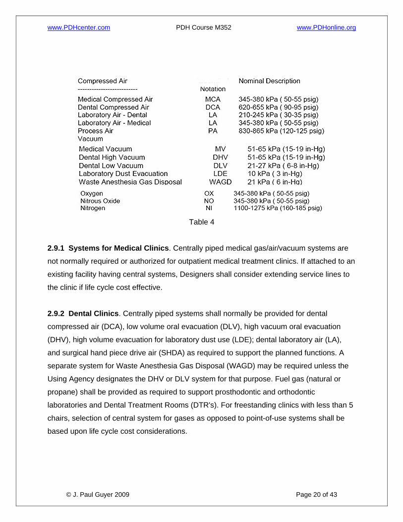
2.9 MEDICAL GAS SYSTEMS. Medical gas systems include: compressed air for medical
and dental patient and laboratory use; vacuum for medical and dental patient use,
laboratory dust collection, waste anesthesia gas disposal; and gases for patient, laboratory,
and equipment use. See Table 4 for general information. Medical gas systems shall be
designed to be safe, reliable, and maintainable.
www.PDHcenter.com PDH Course M352 www.PDHonline.org
© J. Paul Guyer 2009 Page 20 of 43
Table 4
2.9.1 Systems for Medical Clinics. Centrally piped medical gas/air/vacuum systems are
not normally required or authorized for outpatient medical treatment clinics. If attached to an
existing facility having central systems, Designers shall consider extending service lines to
the clinic if life cycle cost effective.
2.9.2 Dental Clinics. Centrally piped systems shall normally be provided for dental
compressed air (DCA), low volume oral evacuation (DLV), high vacuum oral evacuation
(DHV), high volume evacuation for laboratory dust use (LDE); dental laboratory air (LA),
and surgical hand piece drive air (SHDA) as required to support the planned functions. A
separate system for Waste Anesthesia Gas Disposal (WAGD) may be required unless the
Using Agency designates the DHV or DLV system for that purpose. Fuel gas (natural or
propane) shall be provided as required to support prosthodontic and orthodontic
laboratories and Dental Treatment Rooms (DTR's). For freestanding clinics with less than 5
chairs, selection of central system for gases as opposed to point-of-use systems shall be
based upon life cycle cost considerations.
www.PDHcenter.com PDH Course M352 www.PDHonline.org
© J. Paul Guyer 2009 Page 21 of 43
2.9.3 System Control Valves. All medical gas centrally piped systems shall be provided
with shut-off valves and zone valve box assemblies in accordance with NFPA 99.
Additional shutoff valves shall be included as necessary to provide system section isolation
for maintenance or alterations.
2.9.4 Alarm Systems. Medical gas alarm systems shall be provided for all central piped
systems in accordance with NFPA 99.
2.9.5 Gas System Sources (Storage). Gas system sources or storage provisions shall be
designed in accordance with NFPA 99. Flammable and nonflammable storage containers
shall be stored in separate enclosures. Bulk oxygen storage design shall be in accordance
with NFPA 50.
2.9.6 Point-of-Use Sources. Point-of-use cylinders are defined as B, D, or E sizes. The
Designer shall coordinate with the Using Service the provisions for point-of-use cylinder
storage when their use is planned. Storage in the storage room for central system cylinder
banks is permissible. The point-of-use cylinder volume shall be included in the total when
determining the storage room ventilation requirements. Design shall incorporate
Compressed Gas Association requirements of Pamphlet P-2.
2.9.7 Alternative Compressed Air Sources. Alternative compressed air sources such as
pneumatic control air or shop air compressors shall not be used as a source for medical
compressed air, dental compressed air, laboratory air, process air, or surgical hand piece
drive air.
2.9.8 Color Coding and Labeling. Labeling and color identification of piping shall be in
accordance with NFPA 99 and the CGA Pamphlet C-9. System components shall also be
labeled for identification to prevent tampering and inadvertent closing. In particular, shutoff
valves and pressure gauges shall be labeled in accordance with NFPA 99.
2.9.9 Medical Gas Systems Outlets. The Designer shall coordinate the gas types and
outlet quantities with the Using Service. Additional outlets and gas types may be provided
when justified by the Using Service to TMA. All outlets shall comply with the latest edition of
www.PDHcenter.com PDH Course M352 www.PDHonline.org
© J. Paul Guyer 2009 Page 22 of 43
NFPA 99 and the requirements of Compressed Gas Association Pamphlet V-5. There are
DISS and Quick Connect type outlets, with two primary different configurations of the Quick
Connect outlet. Therefore, designer shall also coordinate the outlet type configuration with
the Using Service so that the Users will not have to use an outlet adapter for their existing
medical equipment.
2.9.9.1 Outlets for Non-Medical Function Use. The use of a central medical gas system
to serve an outlet that indirectly supports the medical function such as in a laboratory may
be justified. If so, the branch piping and outlets shall be in accordance with NFPA 99. Non-
medical uses are not permissible except for unique circumstances with documented waiver
requests, coordinated with the user, reviewed individually.
2.9.10 Emergency Power Source. Life-critical medical gas system equipment, requiring
electrical power for generation, operation, or alarm, shall be connected to an emergency
power source. At the discretion of the designer, when requested by the user, dental
compressed air, vacuum, and medical gas systems serving anesthetizing treatment rooms
in outpatient and dental treatment clinics may be connected to an emergency power source.
2.9.11 Medical Compressed Air (MCA). The MCA system shall be an independent central
piped system consisting of two or more medical air compressors and a central receiver, all
conforming to the requirements of NFPA 99. It shall be used only for medical functions
requiring breathable air to support respiration or for air-driven instruments that discharge
into the pharynx. The MCA system shall not be used to satisfy any other compressed air
requirements. The system design shall include automatic operation of the compressors,
including alternating lead/lag status.
2.9.11.1 Air Quality Standards. The medical air compressor(s) shall be specifically
designed and manufactured for this purpose. MCA quality shall be as defined in NFPA 99
(reference 8r). Intake air shall be direct from outdoors or another source of equal or better
quality located in accordance with NFPA 99. Designers are responsible to size and show
routing of medical air intake piping.
www.PDHcenter.com PDH Course M352 www.PDHonline.org
© J. Paul Guyer 2009 Page 23 of 43
2.9.11.2 General Requirements. MCA shall be provided by two or more compressors with
provisions for automatic, alternating, and simultaneous operation. The compressors shall be
sized such that if any one compressor fails, the remaining compressor(s) shall provide
100% of maximum system demand. Provide an alarm to indicate compressor failure that
annunciates at the master medical gas alarm panel. All system components downstream of
the compressors shall be sized for 100% standard system demand and be duplexed. The
receiver shall have an automatic drain feature specified
2.9.11.3 Air Drying. System design shall include an air dryer of either the mechanical
refrigeration or desiccant type. Designers shall closely coordinate with the Using Agency for
each project, to determine whether operating conditions, facility maintenance capabilities,
air dryness limitations, or other factors favor preference of one type over the other for the
given application. Designers are responsible to consider the following:
• When mechanical refrigeration systems are specified, designers shall include
specification of a cycling feature for all systems under 3.7 kW (5 horsepower (hp), to
minimize the possibility of icing and moisture carry-over. Designers shall evaluate
whether anticipated flow conditions will require the cycling feature for systems3.7 kW
(5 hp) and over.
• When desiccant systems are specified, designers shall consult the Using Agency on
dryness limitations. Desiccant dryers are capable of drying the air to a dewpoint as
low as –40 degrees C (-40degrees F), which may be considered too low for some
medical or dental applications. When required by the User, the design shall include
specification of equipment accessories that will permit upward adjustment of air
moisture to the required dewpoint.
• The relative advantages and disadvantages of mechanical refrigeration dryers and
desiccant dryers generate questions. Good arguments may be made for in favor of
either dryer type. Both systems can be successfully utilized in Medical Treatment
Facilities if project-specific conditions and User needs are taken into account and the
equipment is properly specified.
www.PDHcenter.com PDH Course M352 www.PDHonline.org
© J. Paul Guyer 2009 Page 24 of 43
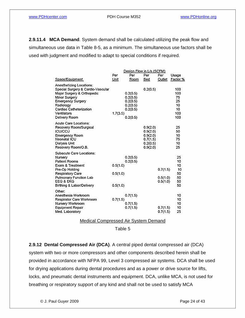
2.9.11.4 MCA Demand. System demand shall be calculated utilizing the peak flow and
simultaneous use data in Table 8-5, as a minimum. The simultaneous use factors shall be
used with judgment and modified to adapt to special conditions if required.
Medical Compressed Air System Demand
Table 5
2.9.12 Dental Compressed Air (DCA). A central piped dental compressed air (DCA)
system with two or more compressors and other components described herein shall be
provided in accordance with NFPA 99, Level 3 compressed air systems. DCA shall be used
for drying applications during dental procedures and as a power or drive source for lifts,
locks, and pneumatic dental instruments and equipment. DCA, unlike MCA, is not used for
breathing or respiratory support of any kind and shall not be used to satisfy MCA
www.PDHcenter.com PDH Course M352 www.PDHonline.org
© J. Paul Guyer 2009 Page 25 of 43
requirements. Air that is normally used for dental laboratory restorative and fabrication
techniques may be provided by the DCA system.
2.9.12.1 Air Quality Standard. DCA quality shall be as defined in NFPA 99, Level 3
compressed air systems. Intake air shall be direct from outdoors or of quality better than
outside air.
2.9.12.2 DCA Components. DCA shall be provided by two or more equally sized
compressors, with provisions for automatic, alternating, and simultaneous operation. Each
compressor shall be sized such that if anyone compressor fails, the remaining
compressor(s) shall provide 65% of standard demand. Provide an alarm to indicate
compressor failure that annunciates to the master medical gas alarm panel. All system
components downstream of compressors shall be sized for maximum combined
compressor output. In-line pressure regulators shall be provided when DCA and dental LA
systems are served by a common compressor. Each laboratory supply main shall have a
pressure regulator. Dryer type may be of either the mechanical refrigeration or desiccant
type, according to project specific operational requirements and the User’s needs.
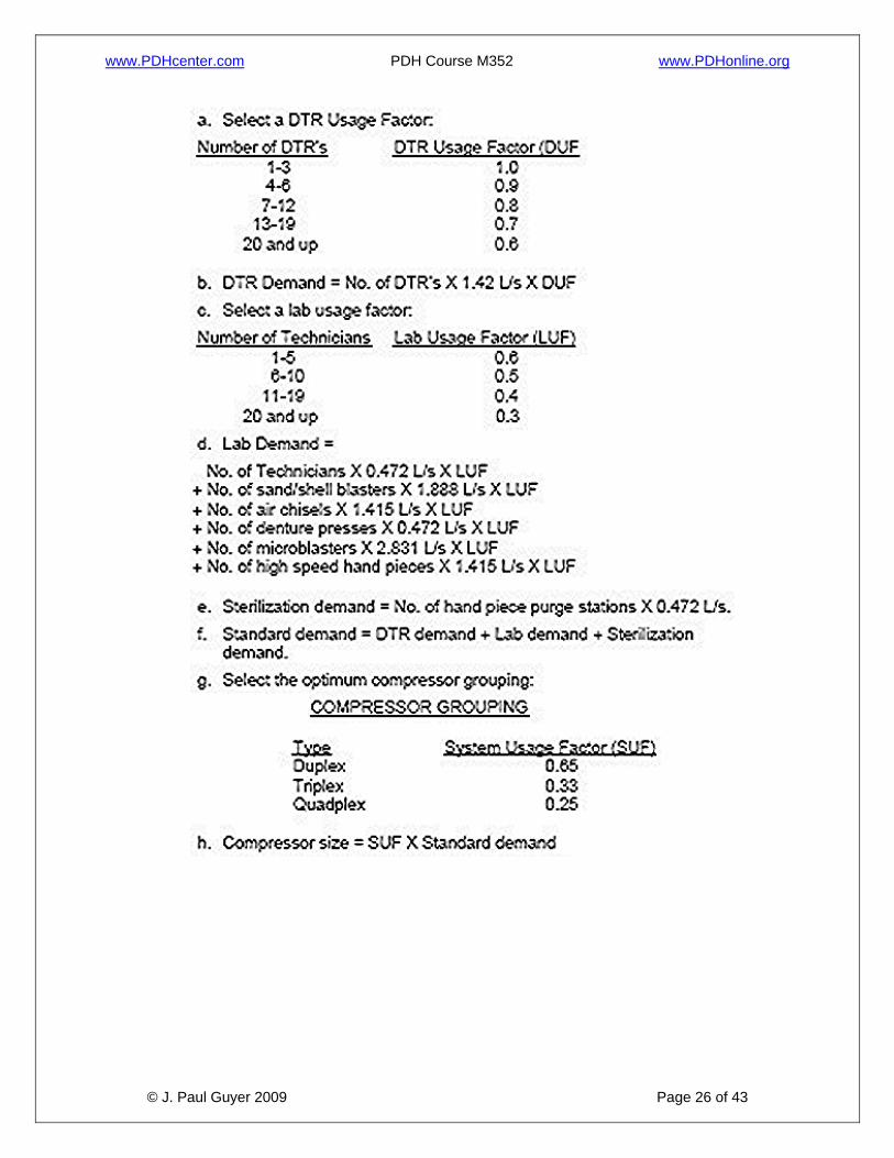
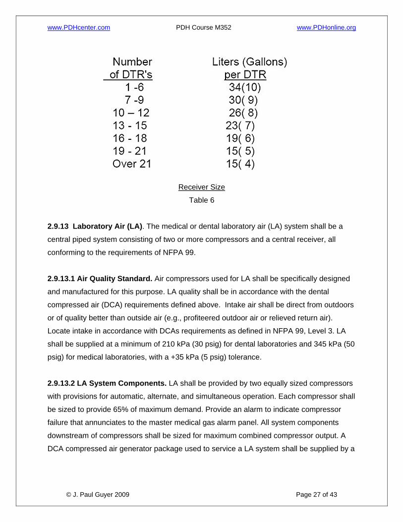
2.9.12.3 DCA System Demand. The system shall be sized using the following criteria:
www.PDHcenter.com PDH Course M352 www.PDHonline.org
© J. Paul Guyer 2009 Page 26 of 43
www.PDHcenter.com PDH Course M352 www.PDHonline.org
© J. Paul Guyer 2009 Page 27 of 43
Receiver Size
Table 6
2.9.13 Laboratory Air (LA). The medical or dental laboratory air (LA) system shall be a
central piped system consisting of two or more compressors and a central receiver, all
conforming to the requirements of NFPA 99.
2.9.13.1 Air Quality Standard. Air compressors used for LA shall be specifically designed
and manufactured for this purpose. LA quality shall be in accordance with the dental
compressed air (DCA) requirements defined above. Intake air shall be direct from outdoors
or of quality better than outside air (e.g., profiteered outdoor air or relieved return air).
Locate intake in accordance with DCAs requirements as defined in NFPA 99, Level 3. LA
shall be supplied at a minimum of 210 kPa (30 psig) for dental laboratories and 345 kPa (50
psig) for medical laboratories, with a +35 kPa (5 psig) tolerance.
2.9.13.2 LA System Components. LA shall be provided by two equally sized compressors
with provisions for automatic, alternate, and simultaneous operation. Each compressor shall
be sized to provide 65% of maximum demand. Provide an alarm to indicate compressor
failure that annunciates to the master medical gas alarm panel. All system components
downstream of compressors shall be sized for maximum combined compressor output. A
DCA compressed air generator package used to service a LA system shall be supplied by a

www.PDHcenter.com PDH Course M352 www.PDHonline.org
© J. Paul Guyer 2009 Page 28 of 43
dedicated main located just downstream of the final package component and inside the
equipment room.
2.9.13.3 LA System Demand. The LA system flow demand shall be determined by the
number of work stations and their function plus the requirements for laboratory equipment.
The user shall provide this information. The designer in conjunction with the user shall
establish the flow rates. Medical LA system flow rate demand shall be 0.5 L/s (1 cfm) per
outlet. Dental LA system flow rate demand is determined by the sizing procedure shown.
The simultaneous use factors shall be as follows in Table 7:
Medical Laboratory Air System Demand
Table 7
2.9.14 Instrument Air (IA). An Instrument Air (IA) system is intended to be used to power
medical devices not related to human respiration (e.g. to power surgical tools, surgical
arms, and surgical columns). This system may be utilized in lieu of a high pressure piped
nitrogen (NI) system. The user in conjunction with the designer will identify IA requirements.
IA shall not be used to satisfy Medical Air (MA) requirements. IA systems shall be designed
in accordance with the requirements of NFPA 99.
2.9.14.1 Air Quality Standard. Air compressors used for IA shall conform to the
requirements of NFPA 99. Instrument air quality shall be as defined in NFPA 99 (reference
8r). It is recommended that intake air be direct from outdoors, but it is permitted to be within
the equipment room.
2.9.14.2 IA System Components. The number of compressors for an IA system shall be a
function of the application; however, at least two compressors or one compressor with a
www.PDHcenter.com PDH Course M352 www.PDHonline.org
© J. Paul Guyer 2009 Page 29 of 43
standby header must be provided as a minimum. Coordinate the compressor arrangement
with the user. Each compressor shall be sized to provide 100% of the demand. Provide an
alarm to indicate compressor failure that annunciates to the master medical gas alarm panel
in accordance with NFPA 99. All system components downstream of compressors shall be
sized for 100% of the system peak demand.
2.9.14.3 IA System Demand. The number of workstations and their functions plus the
requirement of any equipment shall determine the IA system flow demand. The user shall
provide this information. The designer in conjunction with the user shall establish the flow
rates.
2.9.15 Surgical Handpiece Drive Air (SHDA). SHDA may be used as a substitute for
nitrogen to power pneumatic surgical handpieces used in dental procedures. SHDA is not
used for breathing or respiratory support. SHDA must be a separate system from DCA and
dental LA; however, DCA may be used as a first stage of compression.
2.9.16 Medical-Surgical Vacuum System (MV). The medical vacuum (MV) system shall
be a centrally piped, dry vacuum system containing two or more continuous duty pumps
with a central receiver. The system shall meet the requirements of NFPA 99 and shall be
sized so that if one pump fails, the remaining pump(s) can supply 100% of the total system
demand. The system design shall include automatic operation of the vacuum pumps
including alternating lead/lag status. Provide an alarm to indicate vacuum pump failure that
annunciates to the master medical gas alarm panel.
2.9.16.1 Applications. The MV shall be used only for medical functions involving patient
care, therapy, and diagnostic functions as described below. It may also serve DHV
requirements for dental treatment rooms and oral surgeries, and small laboratories in
patient care areas that function in direct support of medical functions. Analysis, research or
teaching laboratory located within a Medical Treatment Facility may also be served by the
MV, provided that a separate system connection or main is provided at the vacuum
receiver, with a shutoff valve and trap with a drain valve. A laboratory not supporting
medical functions shall have a vacuum system separate from the MV.
www.PDHcenter.com PDH Course M352 www.PDHonline.org
© J. Paul Guyer 2009 Page 30 of 43
2.9.16.2 Demand. Vacuum system pumps and piping shall be sized in accordance with
NFPA 99 "Recommended Vacuum Source Sizing” and "Recommended Minimum Pipe
Sizing." Note to “round up” pipe sizes, especially those serving operating rooms including
the risers and laterals. Ascertain the intended staff operational procedures to determine the
need for an additional factor of safety. Indiscriminate opening of vacuum inlets for extended
periods, whether in service or not, requires a factor increase in demand and pipe sizing.
Also, the intended use of “Y-connectors” as a means of increasing available inlets is not
recommended. A justified need for a vacuum inlet shall be accommodated with another wall
inlet, not a Y-connector. Verify with the User’s representative that the number of vacuum
inlets proposed will support the planned medical function operation without the use of Y-
connectors.
2.9.16.3 Performance. System pressure drop shall be a maximum of 10 kPa (3 in-Hg) at
the calculated demand flow rate. A flow rate of 1.4 L/s (3 scfm) per inlet, with no equipment
attached, shall be measured while maintaining 41 kPa (12 in-Hg) vacuum at the farthest
inlet. The 1.4 L/s (3 scfm) without equipment is equivalent to the recommended 0.7 L/s (1.5
scfm) with.
2.9.16.4 Slide Brackets. Vacuum bottle slide brackets shall be provided for all medical
vacuum inlets. Vacuum bottles shall be used at all vacuum inlets to prevent liquids and
solids from entering the piping network. Vacuum bottles shall be provided with an overflow
shut-off device to prevent carry over of fluids or solids into the piping system. Brackets shall
be positioned to provide proper clearance for flow meters and adapters and to eliminate
conflict with electrical receptacles. Thus, it is recommended that the vacuum outlet be
located at either end of a group of medical gas outlets, with the slide bracket to the outside,
e.g. in a healthcare station head wall unit. If two vacuum inlets are required at a given
station, locate one at each end of the outlet group with the slide brackets to the outside. It is
critical to coordinate vacuum inlet and slide locations with the Architectural Designer and
the User’s representative to avoid interference with other items without compromising the
medical function.
2.9.16.5 Vacuum shall be exhausted in accordance with NFPA 99.
www.PDHcenter.com PDH Course M352 www.PDHonline.org
© J. Paul Guyer 2009 Page 31 of 43
2.9.17 Dental High Vacuum (DHV). A central DHV system may be supplied for areas in
dental clinics where MV is required. This system is also a dry system with a central piped
distribution system and receiver; no liquids or solids shall be transported in the distribution
system. Individual separators shall be located in each applicable DTR. The system shall
consist of two or more vacuum pumps and a central receiver. System shall be sized so that
upon failure of one pump the remaining pump(s) shall maintain the minimum vacuum
specified while providing 100% of the calculated demand. The system design shall include
automatic operation of the vacuum pumps including alternating lead/lag status. Provide an
alarm to indicate vacuum pump failure that annunciates to the master medical gas alarm
panel. For dental clinics located in a hospital, the MV system may be used in lieu of a DHV
system.
2.9.17.1 Performance. A minimum vacuum of 65 kPa (19 in-Hg) shall be maintained at the
receiver. System pressure drop shall be such that the most remote inlet will have a
minimum vacuum of 41 kPa (12 in-Hg) under peak demand conditions. System pressure
drop shall be a maximum of 10 kPa (3 in-Hg) at the calculated demand flow rate.
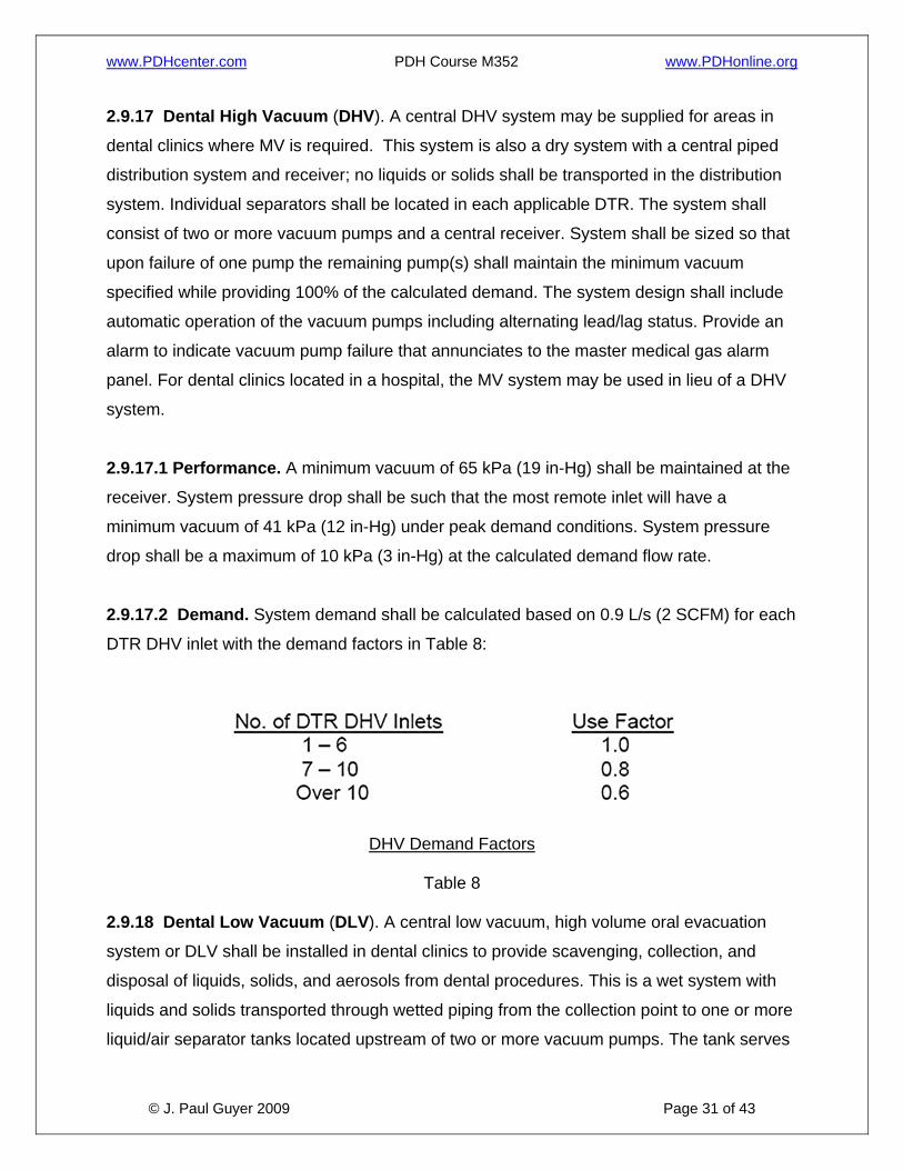
2.9.17.2 Demand. System demand shall be calculated based on 0.9 L/s (2 SCFM) for each
DTR DHV inlet with the demand factors in Table 8:
DHV Demand Factors
Table 8
2.9.18 Dental Low Vacuum (DLV). A central low vacuum, high volume oral evacuation
system or DLV shall be installed in dental clinics to provide scavenging, collection, and
disposal of liquids, solids, and aerosols from dental procedures. This is a wet system with
liquids and solids transported through wetted piping from the collection point to one or more
liquid/air separator tanks located upstream of two or more vacuum pumps. The tank serves
www.PDHcenter.com PDH Course M352 www.PDHonline.org
© J. Paul Guyer 2009 Page 32 of 43
as a collector for the fluids and solids and provides a means of automatic draining for them
by being connected, indirectly, to the sanitary sewer. The tank draining system may include
an automatic wash down feature for larger systems in a Medical Treatment Facility having
greater than 10 DTR’s. The system shall meet the requirements of NFPA 99, Level 3
vacuum systems. The vacuum pumps shall be sized so that when one pump is inoperable,
the remaining pump(s) shall provide the above vacuum pressure and fluid flow for a
minimum of 70% of the system demand. The system design shall include automatic
operation of the vacuum pumps including alternating lead/lag status. Provide an alarm to
indicate vacuum system fault (e.g. pump failure) that annunciates to the master medical gas
alarm panel. Protocol shall include alarm initiation when a pump does not operate when
called for and when a pump operates when not called for.
2.9.18.1 Components. The service inlet normally is floor mounted in a utility center at the
dental chair, or wall mounted with a means of connection to clinical end items such as the
high volume hose. The separator(s) shall receive all liquid, air, and solids upstream of
vacuum pump(s). Liquids and solids shall be discharged from the separator(s), with piped
gravity flow through an air gap into a trapped and vented receptor (e.g. a floor drain or sink,
or standpipe receptor for small system suspended tank installations) connected to the
sanitary waste system. Local codes may require the use of an amalgam separator between
the separator tank and the sanitary waste system to control the discharge of mercury into it.
Coordinate with the Ins local regulatory agency when discharge is to a public sanitary
system. The separator tank shall discharge a minimum of once during a 24-hour interval for
a one-tank system, when a high liquid level sensor activates for a two-tank system, or
multiple daily discharges as recommended by the manufacturer. Separator overflow
protection shall be included to protect during periods of abnormal usage or when the
automatic discharge malfunctions.
2.9.18.2 Performance. The system operating range shall be 21 to 27kPa (6 to 8 in-Hg). A
minimum vacuum of 21 kPa (6 in-Hg) shall be maintained at the farthest inlet. System
pressure drop shall be a maximum of 3 kPa (1 in-Hg) at the calculated demand flow rate. A
flow rate of 3.3 L/s (7 scfm) per inlet shall be measured while maintaining 21kPa (6 in-Hg) at
the farthest inlet.
www.PDHcenter.com PDH Course M352 www.PDHonline.org
© J. Paul Guyer 2009 Page 33 of 43
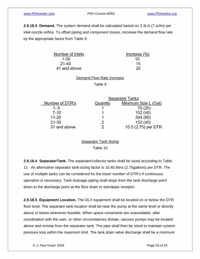
2.9.18.3 Demand. The system demand shall be calculated based on 3.3L/s (7 scfm) per
inlet-nozzle orifice. To offset piping and component losses, increase the demand flow rate
by the appropriate factor from Table 9.
Demand Flow Rate Increase
Table 9
Separator Tank Sizing
Table 10
2.9.18.4 SeparatorTank. The separator/collector tanks shall be sized according to Table
11. An alternative separator tank-sizing factor is 10.45 liters (2.75gallons) per DTR. The
use of multiple tanks can be considered for the lower number of DTR’s if continuous
operation is necessary. Tank drainage piping shall slope from the tank discharge point
down to the discharge point at the floor drain or standpipe receptor.
2.9.18.5 Equipment Location. The DLV equipment shall be located on or below the DTR
floor level. The separator tank location shall be near the pump at the same level or directly
above or below whenever feasible. When space constraints are unavoidable, after
coordination with the user, or other circumstances dictate, vacuum pumps may be located
above and remote from the separator tank. The pipe shall then be sized to maintain system
pressure loss within the maximum limit. The tank drain valve discharge shall be a minimum
www.PDHcenter.com PDH Course M352 www.PDHonline.org
© J. Paul Guyer 2009 Page 34 of 43
150 millimeter (0.5 foot) above the floor to accommodate the pipe slope, drain line turndown
and the indirect connection air gap to the sanitary drainage system receptor. The sanitary
waste centerline of pipe shall be a minimum 0.34meter (1 foot) below the floor to
accommodate the floor drain trap. The equipment room shall be located as near the DTR’s
as possible to minimize distribution piping bends and pipe length. Equipment placement in
the mechanical room shall be arranged to provide the most direct connection to the
distribution piping, the sanitary waste line, and the exhaust discharge point, in that order.
2.9.18.6 Piping Distribution. The piping run from the dental utility center, located on or
recessed into the floor, should continuously slope back to the vacuum source equipment
with limited rise, to facilitate transportation of fluids and particulate. Minimum required slope
is 0.65centimeter per 3.0 meter (1/4 inch per 10 feet). Vacuum shall be increased from the
level specified in Table 8-4 at the rate of 1 in-Hg for every 1.1 foot of rise. Distribution
system piping encased in the slab or buried below the slab shall be a minimum 50
millimeter (2 inch) in diameter. Where maintenance access is required, piping shall be
installed in accessible locations in covered trenches, tunnels, or crawlspaces. Provide
cleanout fittings at every change of direction greater than 45 degrees. Minimum access
space shall be 600 milimeter (2 feet) minimum to within 600 milimeter (2 feet) of the
cleanout and a minimum 150 millimeter ( 0.5 foot) from this point to the cleanout. Specify
DWV fittings to facilitate movement of solids. Enlarging the pipe size shall be considered
depending upon availability of the DWV fittings and relative pipe costs. When overhead pipe
routing cannot be practicably avoided, provide cleanout fittings at the base of all risers and
observe the following requirements:
• Minimize lift height by locating overhead horizontal pipe run as close to floor as
possible.
• Vertical pipe run from inlet to overhead pipe shall be a minimum 40-millimeter (1½-
inch) diameter.
• Overhead pipe shall be not less than 40 millimeter (1½ inch) minimum in diameter.
www.PDHcenter.com PDH Course M352 www.PDHonline.org
© J. Paul Guyer 2009 Page 35 of 43
• The vertical pipe shall “tee” into the top of the overhead branch main.
• The available vacuum level to satisfy performance requirements stated in 8-6.18.2
shall be based on a reduction of the pump-generated vacuum at the rate of 3kPa (1
in-Hg) for each 0.33 meter (1.1 foot) rise.
2.9.18.7 Exhaust. The exhaust pipe material and size, including the connection to the
equipment discharge point, shall be in accordance with manufacturer’s recommendation.
The number of bends and total length shall be minimized. The exhaust piping shall be a
dedicated run from the equipment connection to the discharge point outside the Medical
Treatment Facility. It shall not be connected to any other piping, such as a plumbing vent
line. The exhaust line shall be protected from backflow of air or liquids by detailing an
appropriate discharge arrangement, such as a gooseneck or shroud with screen with a
check valve, or using a flapper valve approved by the manufacturer. The discharge point
shall be separated a minimum of10 meters from the dental or medical compressed air
system intakes and any HVAC system outdoor air intake(s).
2.9.19 Central Dental High-Volume Laboratory Dust Evacuation (LDE).The LDE
system shall scavenge and centrally separate, filter, and collect material trimmings, grinding
debris (toxic and nontoxic), and particulates from polishing and finishing operations in the
dental laboratory. Point of use dust collection may be provided for some operations per
using Military Department requirements.
2.9.19.1 System Components. The LDE system for dental laboratories shall consist
primarily of one belt-driven vacuum pump complete with a preset, field-adjustable ingestion
valve, exhaust silencer, and a central cyclonic separator with a filter bag system.
2.9.19.2 Performance. The vacuum at the farthest inlet shall be a minimum of 4.2 kPa
(1.25 in-Hg). A flow rate of 28 L/s (60 scfm) per technician work station inlet and 71 L/s (150
scfm) per equipment item inlet shall be measured while maintaining the 10 kPa (3 in-Hg) at
the separator. Verify the equipment requirements.
www.PDHcenter.com PDH Course M352 www.PDHonline.org
© J. Paul Guyer 2009 Page 36 of 43
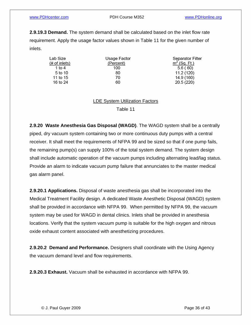
2.9.19.3 Demand. The system demand shall be calculated based on the inlet flow rate
requirement. Apply the usage factor values shown in Table 11 for the given number of
inlets.
LDE System Utilization Factors
Table 11
2.9.20 Waste Anesthesia Gas Disposal (WAGD). The WAGD system shall be a centrally
piped, dry vacuum system containing two or more continuous duty pumps with a central
receiver. It shall meet the requirements of NFPA 99 and be sized so that if one pump fails,
the remaining pump(s) can supply 100% of the total system demand. The system design
shall include automatic operation of the vacuum pumps including alternating lead/lag status.
Provide an alarm to indicate vacuum pump failure that annunciates to the master medical
gas alarm panel.
2.9.20.1 Applications. Disposal of waste anesthesia gas shall be incorporated into the
Medical Treatment Facility design. A dedicated Waste Anesthetic Disposal (WAGD) system
shall be provided in accordance with NFPA 99. When permitted by NFPA 99, the vacuum
system may be used for WAGD in dental clinics. Inlets shall be provided in anesthesia
locations. Verify that the system vacuum pump is suitable for the high oxygen and nitrous
oxide exhaust content associated with anesthetizing procedures.
2.9.20.2 Demand and Performance. Designers shall coordinate with the Using Agency
the vacuum demand level and flow requirements.
2.9.20.3 Exhaust. Vacuum shall be exhausted in accordance with NFPA 99.
www.PDHcenter.com PDH Course M352 www.PDHonline.org
© J. Paul Guyer 2009 Page 37 of 43
2.9.21 Oxygen (OX). Oxygen (OX) is used in the gaseous state to sustain life through direct
delivery to the patient. Oxygen can be stored as a gas in cylinders or as a liquid in bulk
tanks. It is classified as a nonflammable gas; however it can increase the range of
flammability of other materials and gases when present in sufficient concentration. Its
storage requires proper construction and ventilation, in accordance NFPA 99 and NFPA 50.
The oxygen system shall not be used to supply non-patient uses, including equipment in
laboratories or medical equipment maintenance/repair shops. Separate point-of-use
services shall be used for such non-patient applications.
2.9.21.1 Provision of Central Systems. When justified by the number of required outlets
and frequency of use, central oxygen storage and distribution systems shall be provided,
such as is typically the case with medical centers, hospitals, and large ambulatory care
centers. Point-of-use (“roll-in”) cylinders should be utilized for clinical applications involving
few oxygen outlets and infrequent utilization.
2.9.21.2 Emergency Connection. Provide an emergency oxygen supply connection on
the building exterior when the oxygen supply system is located outside of the building. This
connection shall be used as a temporary auxiliary source of supply. Valving and pressure
control devices shall be in accordance with NFPA 99.
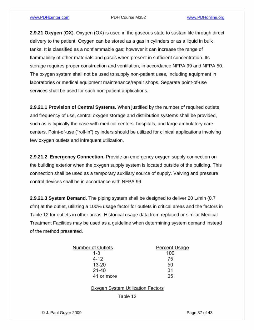
2.9.21.3 System Demand. The piping system shall be designed to deliver 20 L/min (0.7
cfm) at the outlet, utilizing a 100% usage factor for outlets in critical areas and the factors in
Table 12 for outlets in other areas. Historical usage data from replaced or similar Medical
Treatment Facilities may be used as a guideline when determining system demand instead
of the method presented.
Oxygen System Utilization Factors
Table 12
www.PDHcenter.com PDH Course M352 www.PDHonline.org
© J. Paul Guyer 2009 Page 38 of 43
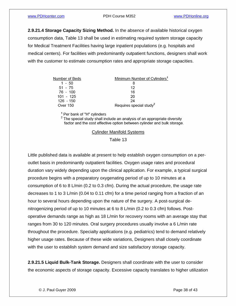
2.9.21.4 Storage Capacity Sizing Method. In the absence of available historical oxygen
consumption data, Table 13 shall be used in estimating required system storage capacity
for Medical Treatment Facilities having large inpatient populations (e.g. hospitals and
medical centers). For facilities with predominantly outpatient functions, designers shall work
with the customer to estimate consumption rates and appropriate storage capacities.
Cylinder Manifold Systems
Table 13
Little published data is available at present to help establish oxygen consumption on a per-
outlet basis in predominantly outpatient facilities. Oxygen usage rates and procedural
duration vary widely depending upon the clinical application. For example, a typical surgical
procedure begins with a preparatory oxygenating period of up to 10 minutes at a
consumption of 6 to 8 L/min (0.2 to 0.3 cfm). During the actual procedure, the usage rate
decreases to 1 to 3 L/min (0.04 to 0.11 cfm) for a time period ranging from a fraction of an
hour to several hours depending upon the nature of the surgery. A post-surgical de-
nitrogenizing period of up to 10 minutes at 6 to 8 L/min (0.2 to 0.3 cfm) follows. Post-
operative demands range as high as 18 L/min for recovery rooms with an average stay that
ranges from 30 to 120 minutes. Oral surgery procedures usually involve a 6 L/min rate
throughout the procedure. Specialty applications (e.g. pediatrics) tend to demand relatively
higher usage rates. Because of these wide variations, Designers shall closely coordinate
with the user to establish system demand and size satisfactory storage capacity.
2.9.21.5 Liquid Bulk-Tank Storage. Designers shall coordinate with the user to consider
the economic aspects of storage capacity. Excessive capacity translates to higher utilization
www.PDHcenter.com PDH Course M352 www.PDHonline.org
© J. Paul Guyer 2009 Page 39 of 43
costs due to boil off. Too little capacity may lead to higher costs because of more frequent
tank refills, which includes vented oxygen cost as well as delivery fees. Designers shall also
consider the availability of oxygen refill service. For remote locations, oversized capacity
may be more practical and economical to minimize deliveries and provide for unexpected
consumption increases. The selection between purchasing or leasing the bulk storage tank
and ancillary equipment shall be coordinated. Both economic and logistic factors relative to
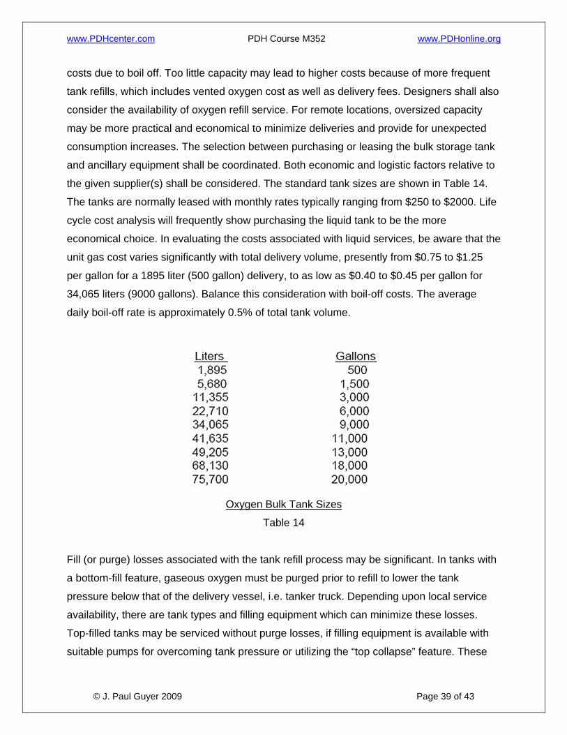
the given supplier(s) shall be considered. The standard tank sizes are shown in Table 14.
The tanks are normally leased with monthly rates typically ranging from $250 to $2000. Life
cycle cost analysis will frequently show purchasing the liquid tank to be the more
economical choice. In evaluating the costs associated with liquid services, be aware that the
unit gas cost varies significantly with total delivery volume, presently from $0.75 to $1.25
per gallon for a 1895 liter (500 gallon) delivery, to as low as $0.40 to $0.45 per gallon for
34,065 liters (9000 gallons). Balance this consideration with boil-off costs. The average
daily boil-off rate is approximately 0.5% of total tank volume.
Oxygen Bulk Tank Sizes
Table 14
Fill (or purge) losses associated with the tank refill process may be significant. In tanks with
a bottom-fill feature, gaseous oxygen must be purged prior to refill to lower the tank
pressure below that of the delivery vessel, i.e. tanker truck. Depending upon local service
availability, there are tank types and filling equipment which can minimize these losses.
Top-filled tanks may be serviced without purge losses, if filling equipment is available with
suitable pumps for overcoming tank pressure or utilizing the “top collapse” feature. These
www.PDHcenter.com PDH Course M352 www.PDHonline.org
© J. Paul Guyer 2009 Page 40 of 43
should be specified when available. The top-filling procedure must be conducted only by
trained personnel to avoid uncontrolled system pressure drop below minimum service
levels.
2.9.21.6 System Monitoring. The central oxygen system design shall facilitate oxygen
system purity monitoring with an outlet placed in the biomedical maintenance area, or other
area, as directed by users. This outlet shall be upstream (on the source side) of all other
oxygen outlets.
2.9.22 Nitrous Oxide (NO). Nitrous oxide is an anesthetic gas capable of inducing the first
and second stages of anesthesia when inhaled. It is classified as a nonflammable gas;
however, it can increase the range of flammability of other materials and gases when
present in sufficient concentration. Its storage requires proper construction and ventilation in
accordance with NFPA 99. Nitrous oxide manifolds shall not be located outside in cold
climates due to the low vapor pressure of nitrous oxide at low temperatures.
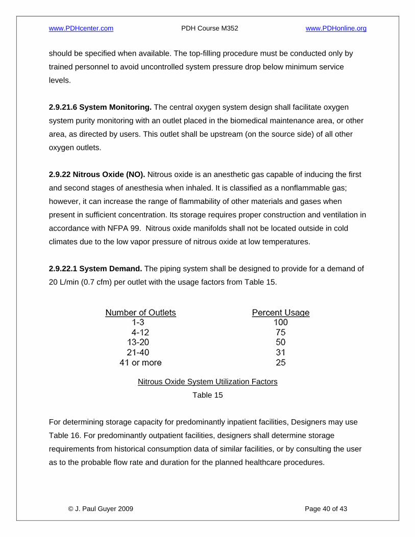
2.9.22.1 System Demand. The piping system shall be designed to provide for a demand of
20 L/min (0.7 cfm) per outlet with the usage factors from Table 15.
Nitrous Oxide System Utilization Factors
Table 15
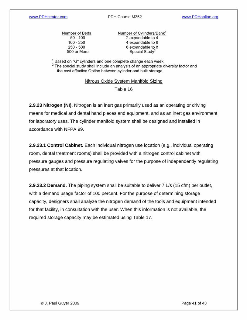
For determining storage capacity for predominantly inpatient facilities, Designers may use
Table 16. For predominantly outpatient facilities, designers shall determine storage
requirements from historical consumption data of similar facilities, or by consulting the user
as to the probable flow rate and duration for the planned healthcare procedures.
www.PDHcenter.com PDH Course M352 www.PDHonline.org
© J. Paul Guyer 2009 Page 41 of 43
Nitrous Oxide System Manifold Sizing
Table 16
2.9.23 Nitrogen (NI). Nitrogen is an inert gas primarily used as an operating or driving
means for medical and dental hand pieces and equipment, and as an inert gas environment
for laboratory uses. The cylinder manifold system shall be designed and installed in
accordance with NFPA 99.
2.9.23.1 Control Cabinet. Each individual nitrogen use location (e.g., individual operating
room, dental treatment rooms) shall be provided with a nitrogen control cabinet with
pressure gauges and pressure regulating valves for the purpose of independently regulating
pressures at that location.
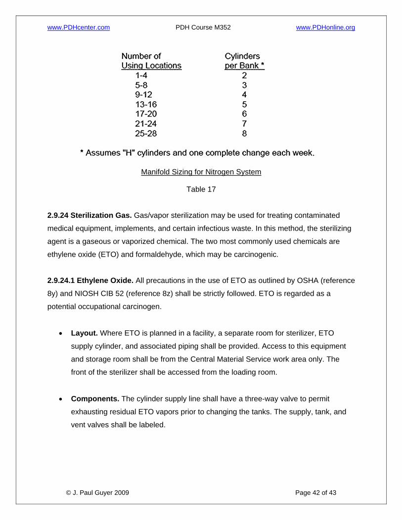
2.9.23.2 Demand. The piping system shall be suitable to deliver 7 L/s (15 cfm) per outlet,
with a demand usage factor of 100 percent. For the purpose of determining storage
capacity, designers shall analyze the nitrogen demand of the tools and equipment intended
for that facility, in consultation with the user. When this information is not available, the
required storage capacity may be estimated using Table 17.
www.PDHcenter.com PDH Course M352 www.PDHonline.org
© J. Paul Guyer 2009 Page 42 of 43
Manifold Sizing for Nitrogen System
Table 17
2.9.24 Sterilization Gas. Gas/vapor sterilization may be used for treating contaminated
medical equipment, implements, and certain infectious waste. In this method, the sterilizing
agent is a gaseous or vaporized chemical. The two most commonly used chemicals are
ethylene oxide (ETO) and formaldehyde, which may be carcinogenic.
2.9.24.1 Ethylene Oxide. All precautions in the use of ETO as outlined by OSHA (reference
8y) and NIOSH CIB 52 (reference 8z) shall be strictly followed. ETO is regarded as a
potential occupational carcinogen.
• Layout. Where ETO is planned in a facility, a separate room for sterilizer, ETO
supply cylinder, and associated piping shall be provided. Access to this equipment
and storage room shall be from the Central Material Service work area only. The
front of the sterilizer shall be accessed from the loading room.
• Components. The cylinder supply line shall have a three-way valve to permit
exhausting residual ETO vapors prior to changing the tanks. The supply, tank, and
vent valves shall be labeled.
www.PDHcenter.com PDH Course M352 www.PDHonline.org
© J. Paul Guyer 2009 Page 43 of 43
• Ventilation. Ventilation shall also be provided for the waste gases from the sterilizer
evacuation line and the drain air gap.
• Emission Control. Some states have adopted legislation that prohibits the release
of ETO sterilizer exhaust gas to the atmosphere. Presently the only available ETO
emission control technology is based on a chemical conversion or scrubber. The
design shall incorporate the necessary provisions to comply with both federal and
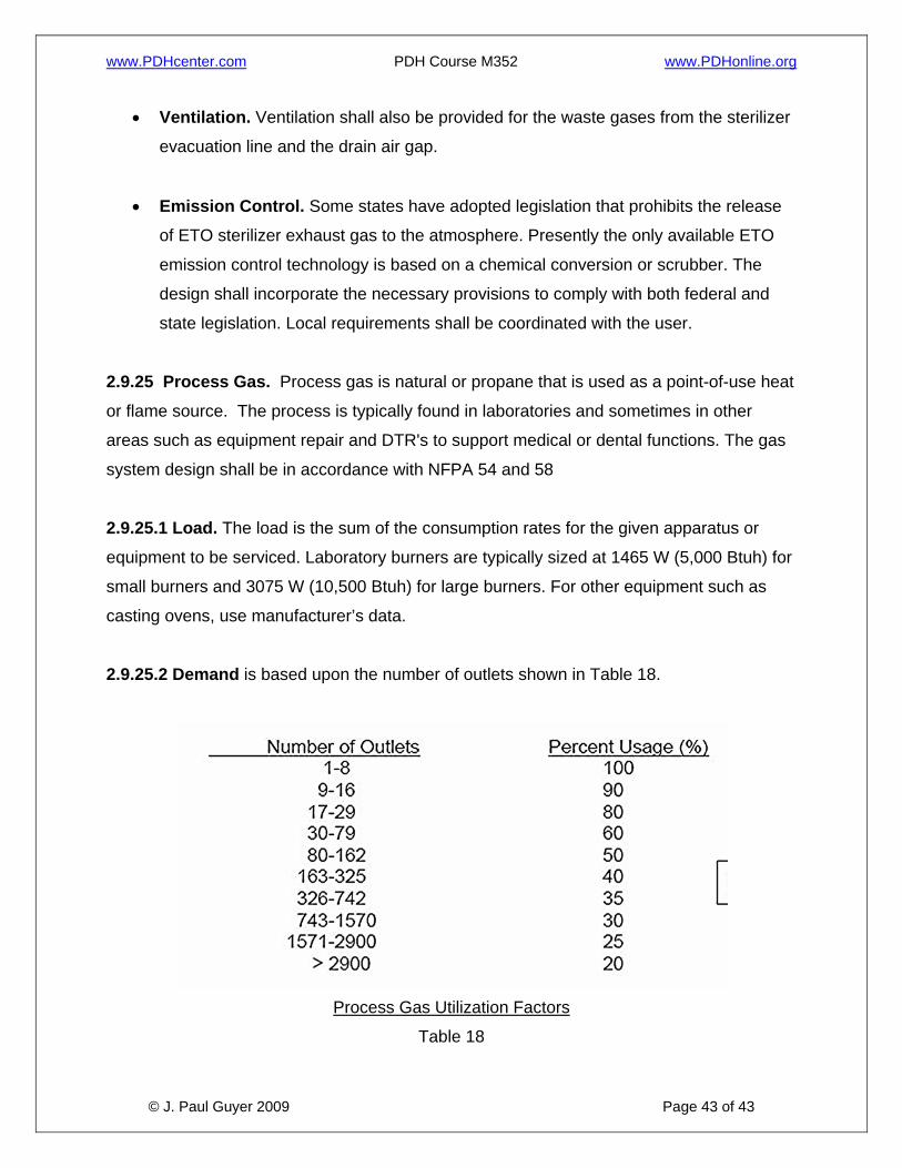
state legislation. Local requirements shall be coordinated with the user. 2.9.25 Process Gas. Process gas is natural or propane that is used as a point-of-use heat
or flame source. The process is typically found in laboratories and sometimes in other
areas such as equipment repair and DTR's to support medical or dental functions. The gas
system design shall be in accordance with NFPA 54 and 58
2.9.25.1 Load. The load is the sum of the consumption rates for the given apparatus or
equipment to be serviced. Laboratory burners are typically sized at 1465 W (5,000 Btuh) for
small burners and 3075 W (10,500 Btuh) for large burners. For other equipment such as
casting ovens, use manufacturer’s data.
2.9.25.2 Demand is based upon the number of outlets shown in Table 18.
Process Gas Utilization Factors
Table 18