an intelligent system for vulnerability and remediation ... · remediation assessment of flooded...
TRANSCRIPT
Loughborough UniversityInstitutional Repository
An intelligent system forvulnerability and
remediation assessment offlooded residential buildings
This item was submitted to Loughborough University's Institutional Repositoryby the/an author.
Additional Information:
• A Doctoral Thesis. Submitted in partial fulfillment of the requirementsfor the award of Doctor of Philosophy of Loughborough University.
Metadata Record: https://dspace.lboro.ac.uk/2134/9150
Publisher: c© Yusef Fiener
Please cite the published version.
This item was submitted to Loughborough’s Institutional Repository (https://dspace.lboro.ac.uk/) by the author and is made available under the
following Creative Commons Licence conditions.
For the full text of this licence, please go to: http://creativecommons.org/licenses/by-nc-nd/2.5/
AN INTELLIGENT SYSTEM FOR VULNERABILITY
AND REMEDIATION ASSESSMENT OF FLOODED
RESIDENTIAL BUILDINGS
By
YUSEF AHMED FIENER
A Doctoral thesis submitted in fulfilment of the requirements for the
award of Doctor of Philosophy of Loughborough University
November, 2011
© Yusef Fiener 2011
ACKNOWLDGEMENT
I am mostly thankful to Allah for giving me the courage and strength to complete
this thesis. Also I would like to take this opportunity to express my sincere thanks
and appreciation to the people who helped me complete this work. I would like to
express my sincere thanks to my academic supervisors Prof.Chimay Anumba and
Dr. Ashraf Elhamalawi, for their continual guidance, support and encouragement
throughout the duration of this project. I consider it a pleasure to have had the
opportunity to work with them and share their valuable knowledge and expertise.
I would like to especially thank Dr Nabil Achour and Dr. Lee Bosher for their
help and advice. I would also like to thank all those who participated in the
survey, interviews, and prototype evaluation and shared their valuable knowledge
and experiences. A final thanks goes to my family, friends for their support and
encouragement.
ABSTRACT
ii
ABSTRACT
Floods are natural phenomena which are a threat to human settlements. Flooding
can result in costly repairs to buildings, loss of business and, in some cases, loss
of life. The forecasts for climate change show a further increased risk of flooding
in future years. Accordingly, the flooding of residential property has been
observed as on the rise in the UK.
It is difficult to prevent floods from occurring, but the effects of flooding can be
managed in an attempt to reduce risks and costs of repair. This can be achieved
through ensuring a good understanding of the problem, and thereby establishing
good management systems which are capable of dealing with all aspects of the
flood.
The use of an intelligent system for assessment and remediation of buildings
subjected to flooding damage can facilitate the management of this problem. Such
a system can provide guidance for the assessment of vulnerability and the repair
of flood damaged residential buildings; this could save time and money through
the use of the advantages and benefits offered by knowledge base systems.
A prototype knowledge base system has been developed in this research. The
system comprises three subsystems: degree of vulnerability assessment
subsystem; remediation options subsystem; and foundation damage assessment
subsystem. The vulnerability assessment subsystem is used to calculate the degree
of vulnerability, which will then be used by the remediation options subsystem to
select remediation options strategy. The vulnerability assessment subsystem can
subsequently be used to calculate the degree to which the building is vulnerable to
ABSTRACT
iii
damage by flooding—even if it is not flooded. Remediation options subsystem
recommended two strategy options: either ordinary remediation options in the
case of vulnerability being low or, alternatively, resilience remediation options in
the case of vulnerability being high. The foundation damage assessment
subsystem is working alone and is used to assess the damage caused by flooding
to the building‘s foundation, and to thereby recommend a repair option based on
the damage caused and foundation type.
The system has been developed based on the knowledge acquired from different
sources and methods, including survey questionnaires, documents, interviews, and
workshops. The system is then evaluated by experts and professionals in the
industry.
The developed system makes a contribution in the management and
standardisation of residential building flooded damage and repair.
KEYWORDS
Flood damage, Vulnerability assessment, knowledge base system and flood,
residential building and flood, flooded building, damage management. Building Vulnerability to flood, flooded building, flood repair, resilient repair.
TABLE OF CONTENTS
iv
TABLE OF CONTENTS
Acknowldgement .............................................................................................................. i Abstract ............................................................................................................................ ii
KeyWords ....................................................................................................................... iii Table of Contents ........................................................................................................... iv
List of Figures ................................................................................................................ vii List of Tables.................................................................................................................... x CHAPTER 1 INTRODUCTION ............................................................................... 1
1.1 Preface.................................................................................................................... 1 1.2 Rationale for the research ...................................................................................... 1
1.3 Research Aims and Objectives ............................................................................ 10 1.4 Purpose of developing the knowledge base system ............................................. 11 1.5 Justification for the research ................................................................................ 13
1.6 Research Methods ................................................................................................ 15 CHAPTER 2 RESEARCH METHODOLOGY..................................................... 19
2.1 Introduction .......................................................................................................... 19 2.2 Review of reseArch methods ............................................................................... 19
2.2.1 Quantitative research .............................................................................. 20
2.2.2 Qualitative Research .............................................................................. 22 2.2.3 Triangulation Research .......................................................................... 25
2.3 Methodology Selected for the Research .............................................................. 25 2.3.1 Methods used.......................................................................................... 26 2.3.2 Literature Review ................................................................................... 28
2.3.3 Case studies ............................................................................................ 29 2.3.4 Knowledge Acquisition .......................................................................... 31
2.3.5 Prototype development........................................................................... 43 2.3.6 Evaluation............................................................................................... 46
2.4 Summary .............................................................................................................. 47
CHAPTER 3 VULNERABILITY ASSESSMENT................................................ 49 3.1 Introduction .......................................................................................................... 49
3.2 Definition of vulnerability ................................................................................... 49 3.3 Vulnerability assessment...................................................................................... 51
3.3.1 Examples of vulnerability and hazard assessment methods................... 52
3.4 The proposed method developed to calculate the vulnerability of residential buildings to flood damage.................................................................................... 62
3.4.1 The steps IN THE DEVELOPMENT of THE degree of vulnerability assessment model.............................................................. 64
3.5 Summary .............................................................................................................. 91
CHAPTER 4 REVIEW OF FLOOD DAMAGE MANAGEMENT AND
KNOWLEDGE BASE SYSTEMS ................................................................... 92
4.1 Introduction .......................................................................................................... 92 4.2 Review of flood damage management................................................................. 92
4.2.1 Flood types ............................................................................................. 92
4.2.2 Causes of flooding.................................................................................. 97 4.2.3 Sources of flooding ................................................................................ 98
4.3 Flood risk in the UK .......................................................................................... 100 4.4 Flood damage to buildings ................................................................................. 105
4.4.1 Factors affecting building flood damage.............................................. 108

TABLE OF CONTENTS
v
4.5 Damage repair of flooded buildings................................................................... 128 4.5.1 Management of damage to flooded residential buildings .................... 128 4.5.2 Issues in flood repair and the need to establish repair standards ......... 130
4.5.3 Flooded building damage repair options .............................................. 132 4.6 Review of Knowledge base systems .................................................................. 136
4.6.1 Artificial Intelligence ........................................................................... 136 4.6.2 Concept and Components of a Knowledge base system (ES) ............. 140 4.6.3 Types of knowledge base system ......................................................... 144
4.6.4 Knowledge base system applications ................................................... 144 4.6.5 Knowledge base systems structure and design .................................... 147
4.7 Applications of knowledge base systems in civil engineering .......................... 156 4.8 Summary ............................................................................................................ 160 CHAPTER 5 KNOWLEDGE ACQUISITION FOR PROTOTYPE
DEVLOPMENT ............................................................................................... 162 5.1 Introduction ........................................................................................................ 162
5.2 Methodology used.............................................................................................. 162 5.2.1 The questionnaire surveys .................................................................... 164 5.2.2 Review of technical publications and manuals .................................... 170
5.3 Flood damage repair options.............................................................................. 178 5.3.1 flood damage repair options ................................................................. 179
5.4 Repair options used in the proposed system ...................................................... 184 5.4.1 Standard repair options......................................................................... 184
5.5 Summary ............................................................................................................ 216
CHAPTER 6 DEVELOPMENT AND OPERATION OF THE
PROTOTYPE SYSTEM ................................................................................. 217 6.1 INTRODUCTION ............................................................................................. 217
6.2 Degree of Vulnerability and remediation assessment of flooded Residential building System (VRAFRBS)............................................................................ 217
6.2.1 The functions of the system ................................................................. 217 6.2.2 The system architecture........................................................................ 218 6.2.3 System Development............................................................................ 220
6.3 Operation of the prototype system ..................................................................... 230 6.3.1 System Requirements ........................................................................... 230
6.3.2 User requirements ................................................................................ 231 6.3.3 Starting the prototype system ............................................................... 231
6.4 Summary ............................................................................................................ 249
CHAPTER 7 EVALUATION OF THE PROTOTYPE SYSTEM .................... 251 7.1 Introduction ........................................................................................................ 251
7.2 Evaluation aim and objectives ........................................................................... 251 7.3 Evaluation methodology .................................................................................... 252
7.3.1 Evaluation approach ............................................................................. 253
7.3.2 Questionnaire design ............................................................................ 255 7.4 Evaluation results ............................................................................................... 255
7.5 Discussion .......................................................................................................... 258 7.5.1 Results .................................................................................................. 259 7.5.2 Suggestions for improvement............................................................... 261
7.5.3 Benefits of the prototype ...................................................................... 262 7.6 Summary ............................................................................................................ 262
CHAPTER 8 CONCLUSION AND RECOMMENDATIONS .......................... 264 8.1 Introduction ........................................................................................................ 264

TABLE OF CONTENTS
vi
8.2 Summary ............................................................................................................ 264 8.3 Benefits Of The Prototype System .................................................................... 270 8.4 Limitations Of The Prototype Sytem ................................................................. 271
8.5 Conclusions ........................................................................................................ 272 8.6 Recommendations For Further Research ........................................................... 275
8.7 Closing Remarks ................................................................................................ 277 References .................................................................................................................... 278 APPENDIX-A .............................................................................................................. 291
APPENDIX-B .............................................................................................................. 293 APPENDIX-C .............................................................................................................. 301
APPENDIX-D .............................................................................................................. 302

LIST OF FIGURES
vii
LIST OF FIGURES
Figure 0-1: Steps to reinstate or insure a building (Association of British Insurers and the National Flood Forum, 2005) ...........................................................5
Figure 0-2: Repair process for a flooded building (CIRIA, 2005)...........................6 Figure 0-3: Level of homeowner satisfaction with respect to reinstatement time
(Woodhead, 2008).........................................................................................8 Figure 0-4: Stages at which the system can be involved during the steps to
reinstate or insure a building. Adapted from Association of British Insurers
(ABI) and the National Flood Forum (2005) ..............................................12 Figure 0-5: Stages at which the system can be involved during the repair process
for a flooded building. Adapted from CIRIA (2005)..................................13 Figure 0-6: A flowchart of the research process and methodology .......................18 Figure 2-1: Triangulation: making inferences and drawing conclusions from both
quantitative and qualitative data (Fellows & Liu, 2008). ...........................25 Figure 2-2: Methods of knowledge acquisition (Source: Turban & Aronson, 2001)
.....................................................................................................................33 Figure 2-3: Knowledge Acquisition Matrix presents several tools used in order to
acquire various types of knowledge (Emberey et al., 2007) .......................34
Figure 2-4: Prototyping process (Sommerville, 2001)...........................................44 Figure 2-5: Prototyping methodology (Sommerville, 2001)..................................45
Figure 2-6: The main steps in developing the prototype system............................46 Figure 3-1: The overall vulnerability calculation (Villagran, 2006) ......................59 Figure 3-2: The mechanism of vulnerability of buildings to flood damage...........63
Figure 3-3: Major steps of vulnerability assessment used in this research ............65 Figure 3-4: Extent of chalk on the UK geological map (EA, 2006) ......................71
Figure 3-5: Groundwater rising during winter in chalk soil (Cobby et al., 2009) .72 Figure 3-6: Depth-damage curve differentiated by flood duration ........................74 Figure 3-7: Difference in water depth dH (DCLG, 2007)......................................75
Figure 3-8: Flood damage curve (Nicholas, Holt & Proverbs, 2001) ....................76 Figure 3-9: Sources of floodwater entry (ODPM, 2003) .......................................80
Figure 3-10: Vulnerability assessment flowchart...................................................90 Figure 4-1: Fluvial flooding (CIRIA, 2004b).........................................................93 Figure 4-2: Groundwater flooding (CIRIA, 2004b)...............................................94
Figure 4-3: Overland flow flooding (CIRIA, 2004b).............................................95 Figure 4-4: Flooding from artificial drainage systems (CIRIA, 2004b) ................96
Figure 4-5: Flooding from infrastructure failure (CIRIA, 2004b). ........................97 Figure 4-6: Causes of property flooding based on Autumn 2000 floods (ODPM,
2003). ..........................................................................................................98
Figure 4-7: Some sources of flooding (CIRIA, 2004b) .......................................100 Figure 4-8: Flood entry routes into a house (Environment Agency, 2003) .........107
Figure 4-9: Difference in water depth (dH) (DCLG and EA, 2007)....................111 Figure 4-10: Flood damage curve (Nicholas, Holt & Proverbs, 2001) ................112 Figure 4-11: Depth-damage curve differentiated by flood duration ....................113
Figure 4-12: Typical duration of different types of flood (DCLG and EA, 2007)...................................................................................................................113
Figure 4-13: Victorian and prior foundations type (Glover, 2006)......................117 Figure 4-14: Typical 1930 domestic foundations type (Glover, 2006)................118 Figure 4-15: Modern short-bored pile foundations type (Glover, 2006) .............118
LIST OF FIGURES
viii
Figure 4-16: Suspended timber floor (adopted from ‗Preparing for Floods‘) (ODPM, 2003) ..........................................................................................120
Figure 4-17: Solid concrete floor (adopted from ‗Preparing for Floods‘) (ODPM,
2003) .........................................................................................................121 Figure 4-18: Suspended concrete floor (adopted from ‗Preparing for Floods'
(ODPM, 2003) ..........................................................................................122 Figure 4-19: Wall types (CIRIA, 2003b, Advice sheet 4) ...................................123 Figure 4-20: Wall types (CIRIA, 2003, Advice sheet 4) .....................................124
Figure 4-21: Repair process for a flooded building (CIRIA, 2005).....................129 Figure 4-22 Depth/damage profiles for different flood resistance and resilience
packages (DEFRA, 2008) .........................................................................135 Figure 4-23: Major areas of artificial intelligence (AI) (Turban & Aronson, 2001)
...................................................................................................................137
Figure 4-24: Knowledge base system concepts (Giarratano, 1998).....................141 Figure 4-25: The basic elements of an ES (Arian & Pheng, 2006)......................143
Figure 4-26: Structure of knowledge base system components (Turban & Aronson, [date?]; Liang, 2005) .................................................................143
Figure 4-27: Knowledge base system lifecycle model (Awad, 1996) .................148
Figure 4-28: Classification of building tools (Awad, 1996) ................................155 Figure 5-1: Building elements that are subject to flood damage with respect to
flood depth ................................................................................................173 Figure 5-2: Categorised building elements (external walls) ................................174 Figure 5-3: Categorised building elements (floors) .............................................175
Figure 5-4: Categorised building elements (external walls/internal walls and partitions) ..................................................................................................175
Figure 5-5: Categorised building elements (internal walls and partitions) ..........176
Figure 5-6: Categorised building elements (joinery and fittings) ........................176 Figure 5-7: Categorised building elements (services)..........................................177
Figure 5-8: Categorised building elements (sanitary ware) .................................177 Figure 5-9: Categorised building elements (drainage) .........................................178 Figure 6-1: The modular architecture of the prototype system ............................219
Figure 6-2: The main screen of the prototype system ..........................................221 Figure 6-3: The operation flowchart of the prototype system..............................222
Figure 6-4: The degree of vulnerability assessment sub-system flowchart .........223 Figure 6-5: Remediation assessment subsystem flowchart..................................229 Figure 6-6: The main screen.................................................................................232
Figure 6-7: Foundation damage assessment flowchart ........................................233 Figure 6-8: The degree of vulnerability assessment screen .................................235
Figure 6-9: The output screen of the degree of vulnerability assessment ............236 Figure 6-10: The reports screen ...........................................................................237 Figure 6-11: The screen displayed when the user clicks the remediation option
button ........................................................................................................240 Figure 6-12: The start screen of the remediation option view .............................241
Figure 6-13: Flood depth selection.......................................................................241 Figure 6-14: Building elements selection screen .................................................242 Figure 6-15: Subcategorise under the building element (Floors).........................243
Figure 6-16: Example of the remediation viewed in case of concrete floor ........244 Figure 6-17: The start screen of the foundation damage assessment and
remediation subsystem ..............................................................................245 Figure 6-18: Example of questions used by the subsystem .................................246

LIST OF FIGURES
ix
Figure 6-19: Example of instruction and inquiry used by the system..................247 Figure 6-20: Example of remediation options viewed by the subsystem ............247 Figure 6-21: Underpinning methods viewed in the form of buttons....................248
Figure 6-22: Example of the underpinning method viewed by the system..........249 Figure 7-1: Overall rating from the experts on the system performance .............259
Figure 7-2: Overall rating of the applicability of the prototype system to the flooded residential building management industry ...................................260
Figure 7-3: Overall rating of the prototype system ..............................................261
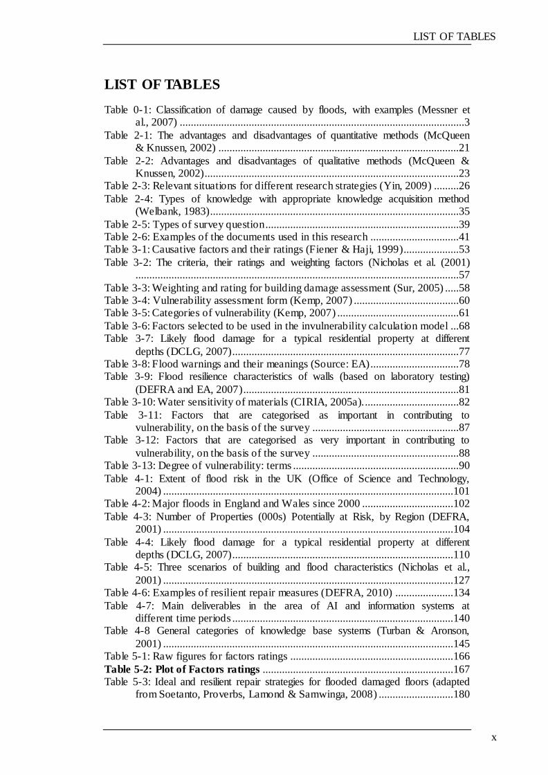
LIST OF TABLES
x
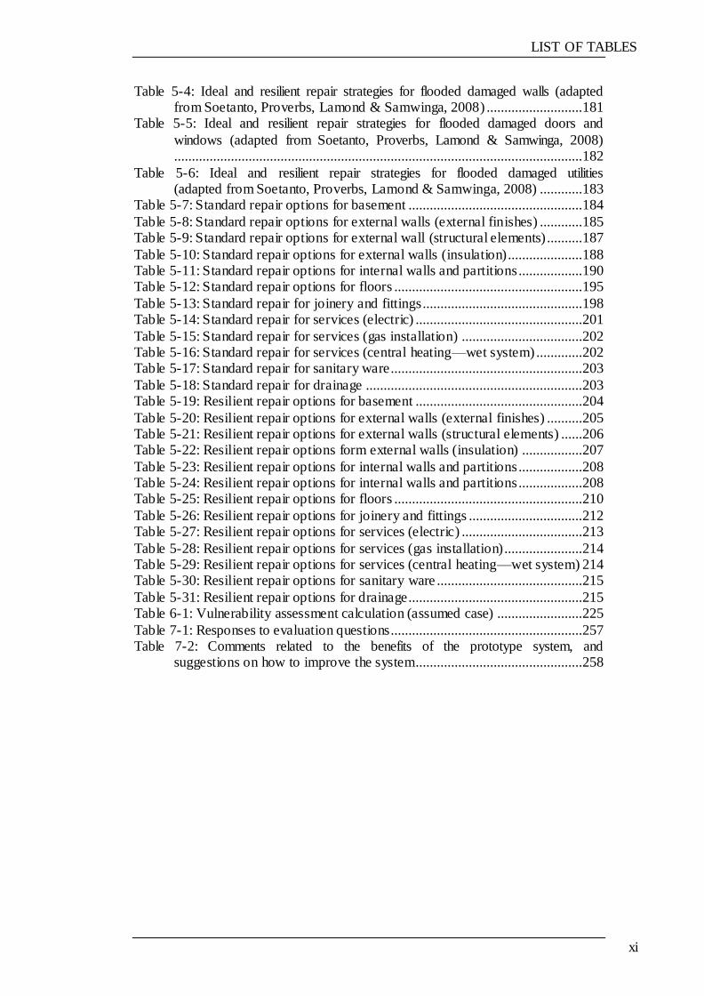
LIST OF TABLES
Table 0-1: Classification of damage caused by floods, with examples (Messner et al., 2007) .......................................................................................................3
Table 2-1: The advantages and disadvantages of quantitative methods (McQueen & Knussen, 2002) .......................................................................................21
Table 2-2: Advantages and disadvantages of qualitative methods (McQueen & Knussen, 2002)............................................................................................23
Table 2-3: Relevant situations for different research strategies (Yin, 2009) .........26
Table 2-4: Types of knowledge with appropriate knowledge acquisition method (Welbank, 1983)..........................................................................................35
Table 2-5: Types of survey question ......................................................................39 Table 2-6: Examples of the documents used in this research ................................41 Table 3-1: Causative factors and their ratings (Fiener & Haji, 1999)....................53
Table 3-2: The criteria, their ratings and weighting factors (Nicholas et al. (2001).....................................................................................................................57
Table 3-3: Weighting and rating for building damage assessment (Sur, 2005) .....58 Table 3-4: Vulnerability assessment form (Kemp, 2007) ......................................60 Table 3-5: Categories of vulnerability (Kemp, 2007) ............................................61
Table 3-6: Factors selected to be used in the invulnerability calculation model ...68 Table 3-7: Likely flood damage for a typical residential property at different
depths (DCLG, 2007)..................................................................................77 Table 3-8: Flood warnings and their meanings (Source: EA)................................78 Table 3-9: Flood resilience characteristics of walls (based on laboratory testing)
(DEFRA and EA, 2007)..............................................................................81 Table 3-10: Water sensitivity of materials (CIRIA, 2005a)...................................82
Table 3-11: Factors that are categorised as important in contributing to vulnerability, on the basis of the survey .....................................................87
Table 3-12: Factors that are categorised as very important in contributing to
vulnerability, on the basis of the survey .....................................................88 Table 3-13: Degree of vulnerability: terms ............................................................90
Table 4-1: Extent of flood risk in the UK (Office of Science and Technology, 2004) .........................................................................................................101
Table 4-2: Major floods in England and Wales since 2000 .................................102
Table 4-3: Number of Properties (000s) Potentially at Risk, by Region (DEFRA, 2001) .........................................................................................................104
Table 4-4: Likely flood damage for a typical residential property at different depths (DCLG, 2007)................................................................................110
Table 4-5: Three scenarios of building and flood characteristics (Nicholas et al.,
2001) .........................................................................................................127 Table 4-6: Examples of resilient repair measures (DEFRA, 2010) .....................134
Table 4-7: Main deliverables in the area of AI and information systems at different time periods ................................................................................140
Table 4-8 General categories of knowledge base systems (Turban & Aronson,
2001) .........................................................................................................145 Table 5-1: Raw figures for factors ratings ...........................................................166
Table 5-2: Plot of Factors ratings .....................................................................167 Table 5-3: Ideal and resilient repair strategies for flooded damaged floors (adapted
from Soetanto, Proverbs, Lamond & Samwinga, 2008) ...........................180
LIST OF TABLES
xi
Table 5-4: Ideal and resilient repair strategies for flooded damaged walls (adapted from Soetanto, Proverbs, Lamond & Samwinga, 2008) ...........................181
Table 5-5: Ideal and resilient repair strategies for flooded damaged doors and
windows (adapted from Soetanto, Proverbs, Lamond & Samwinga, 2008)...................................................................................................................182
Table 5-6: Ideal and resilient repair strategies for flooded damaged utilities (adapted from Soetanto, Proverbs, Lamond & Samwinga, 2008) ............183
Table 5-7: Standard repair options for basement .................................................184
Table 5-8: Standard repair options for external walls (external finishes) ............185 Table 5-9: Standard repair options for external wall (structural elements) ..........187
Table 5-10: Standard repair options for external walls (insulation).....................188 Table 5-11: Standard repair options for internal walls and partitions..................190 Table 5-12: Standard repair options for floors .....................................................195
Table 5-13: Standard repair for joinery and fittings.............................................198 Table 5-14: Standard repair for services (electric) ...............................................201
Table 5-15: Standard repair for services (gas installation) ..................................202 Table 5-16: Standard repair for services (central heating—wet system) .............202 Table 5-17: Standard repair for sanitary ware......................................................203
Table 5-18: Standard repair for drainage .............................................................203 Table 5-19: Resilient repair options for basement ...............................................204
Table 5-20: Resilient repair options for external walls (external finishes) ..........205 Table 5-21: Resilient repair options for external walls (structural elements) ......206 Table 5-22: Resilient repair options form external walls (insulation) .................207
Table 5-23: Resilient repair options for internal walls and partitions..................208 Table 5-24: Resilient repair options for internal walls and partitions..................208 Table 5-25: Resilient repair options for floors .....................................................210
Table 5-26: Resilient repair options for joinery and fittings ................................212 Table 5-27: Resilient repair options for services (electric) ..................................213
Table 5-28: Resilient repair options for services (gas installation)......................214 Table 5-29: Resilient repair options for services (central heating—wet system) 214 Table 5-30: Resilient repair options for sanitary ware .........................................215
Table 5-31: Resilient repair options for drainage.................................................215 Table 6-1: Vulnerability assessment calculation (assumed case) ........................225
Table 7-1: Responses to evaluation questions......................................................257 Table 7-2: Comments related to the benefits of the prototype system, and
suggestions on how to improve the system...............................................258

CHAPTER 1 INTRODUCTION
1.1 PREFACE
This chapter provides an introduction for the entire thesis. It focuses on the
rationale behind the study, its aim and objectives, and details a summary of
methodologies as well as research processes. This chapter also outlines the thesis
and the contents of each chapter.
1.2 RATIONALE FOR THE RESEARCH
Floods are natural phenomena which pose a threat to human settlements. Floods
are the most common natural disasters, representing approximately 35% of the
total number of natural disasters reported around the world (O. le Polain de
Waroux (2011). Flooding can result in costly repairs to buildings and affect their
price, loss of business and, in some cases, loss of life (Jonkman and Vrijling,
2008; Lamond et al., 2007a). The forecasts for climate change show a further
increased risk of flooding in future years.
In one of their reports, the Environment agency (EA) states some figures on the
risk of flood:
‗One in six homes in England is at risk of flooding; over 2.4 million properties
at risk of flooding from rivers or the sea in England, of which nearly half a
million are at significant risk; One million of these are also vulnerable to
surface water flooding with a further 3.8 million properties susceptible to
surface water flooding alone; 55 per cent living in flood risk areas knew they
were at risk and for these three out of five of them had taken some action to
prepare for flooding‘ (EA, 2009; EA,2009a).
INTRODUCTION
2
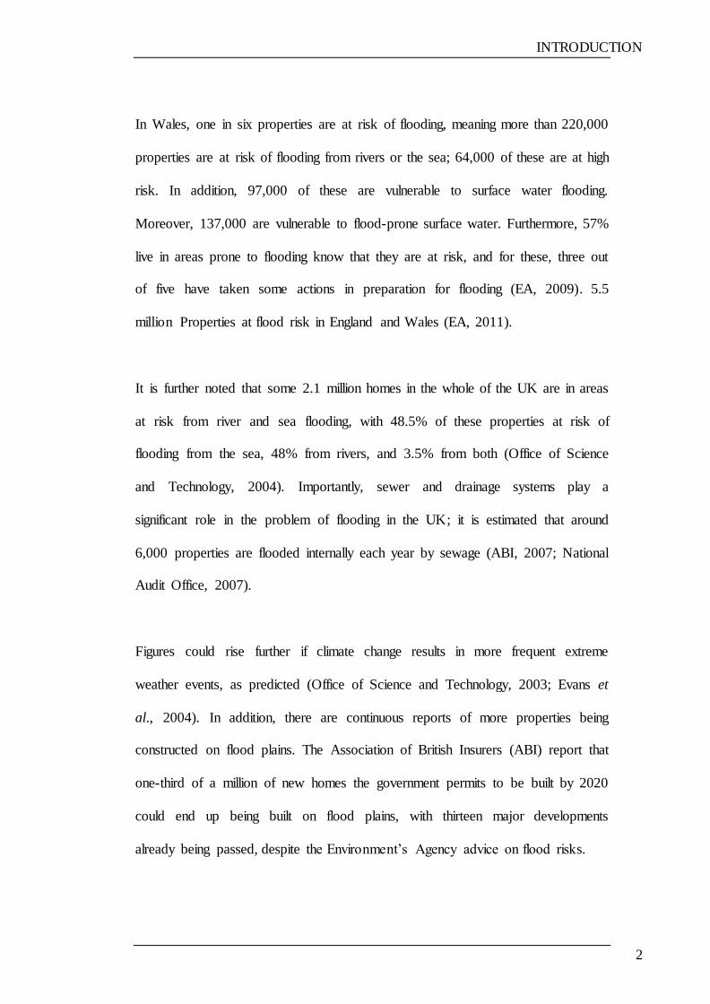
In Wales, one in six properties are at risk of flooding, meaning more than 220,000
properties are at risk of flooding from rivers or the sea; 64,000 of these are at high
risk. In addition, 97,000 of these are vulnerable to surface water flooding.
Moreover, 137,000 are vulnerable to flood-prone surface water. Furthermore, 57%
live in areas prone to flooding know that they are at risk, and for these, three out
of five have taken some actions in preparation for flooding (EA, 2009). 5.5
million Properties at flood risk in England and Wales (EA, 2011).
It is further noted that some 2.1 million homes in the whole of the UK are in areas
at risk from river and sea flooding, with 48.5% of these properties at risk of
flooding from the sea, 48% from rivers, and 3.5% from both (Office of Science
and Technology, 2004). Importantly, sewer and drainage systems play a
significant role in the problem of flooding in the UK; it is estimated that around
6,000 properties are flooded internally each year by sewage (ABI, 2007; National
Audit Office, 2007).
Figures could rise further if climate change results in more frequent extreme
weather events, as predicted (Office of Science and Technology, 2003; Evans et
al., 2004). In addition, there are continuous reports of more properties being
constructed on flood plains. The Association of British Insurers (ABI) report that
one-third of a million of new homes the government permits to be built by 2020
could end up being built on flood plains, with thirteen major developments
already being passed, despite the Environment‘s Agency advice on flood risks.
INTRODUCTION
3
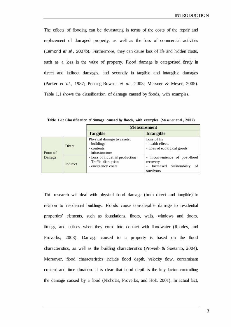
The effects of flooding can be devastating in terms of the costs of the repair and
replacement of damaged property, as well as the loss of commercial activities
(Lamond et al., 2007b). Furthermore, they can cause loss of life and hidden costs,
such as a loss in the value of property. Flood damage is categorised firstly in
direct and indirect damages, and secondly in tangible and intangible damages
(Parker et al., 1987; Penning-Rowsell et al., 2003; Messner & Meyer, 2005).
Table 1.1 shows the classification of damage caused by floods, with examples.
Table 1-1: Classification of damage caused by floods, with examples (Messner et al., 2007)
Measurement
Tangible Intangible
Form of
Damage
Direct
Physical damage to assets:
- buildings
- contents
- infrastructure
Loss of life
- health effects
- Loss of ecological goods
Indirect
- Loss of industrial production
- Traffic disruption
- emergency costs
- Inconvenience of post-flood
recovery
- Increased vulnerability of
survivors
This research will deal with physical flood damage (both direct and tangible) in
relation to residential buildings. Floods cause considerable damage to residential
properties‘ elements, such as foundations, floors, walls, windows and doors,
fittings, and utilities when they come into contact with floodwater (Rhodes, and
Proverbs, 2008). Damage caused to a property is based on the flood
characteristics, as well as the building characteristics (Proverb & Soetanto, 2004).
Moreover, flood characteristics include flood depth, velocity flow, contaminant
content and time duration. It is clear that flood depth is the key factor controlling
the damage caused by a flood (Nicholas, Proverbs, and Holt, 2001). In actual fact,
INTRODUCTION
4
the effect of the other factors is not clear since it is difficult to measure these, and
there is also a lack of clear data showing the influence of such factors.
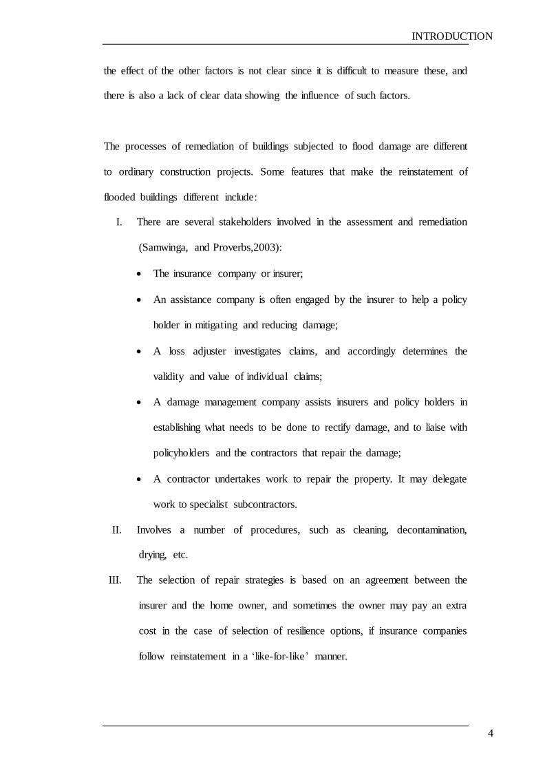
The processes of remediation of buildings subjected to flood damage are different
to ordinary construction projects. Some features that make the reinstatement of
flooded buildings different include:
I. There are several stakeholders involved in the assessment and remediation
(Samwinga, and Proverbs,2003):
The insurance company or insurer;
An assistance company is often engaged by the insurer to help a policy
holder in mitigating and reducing damage;
A loss adjuster investigates claims, and accordingly determines the
validity and value of individual claims;
A damage management company assists insurers and policy holders in
establishing what needs to be done to rectify damage, and to liaise with
policyholders and the contractors that repair the damage;
A contractor undertakes work to repair the property. It may delegate
work to specialist subcontractors.
II. Involves a number of procedures, such as cleaning, decontamination,
drying, etc.
III. The selection of repair strategies is based on an agreement between the
insurer and the home owner, and sometimes the owner may pay an extra
cost in the case of selection of resilience options, if insurance companies
follow reinstatement in a ‗like-for-like‘ manner.
INTRODUCTION
5
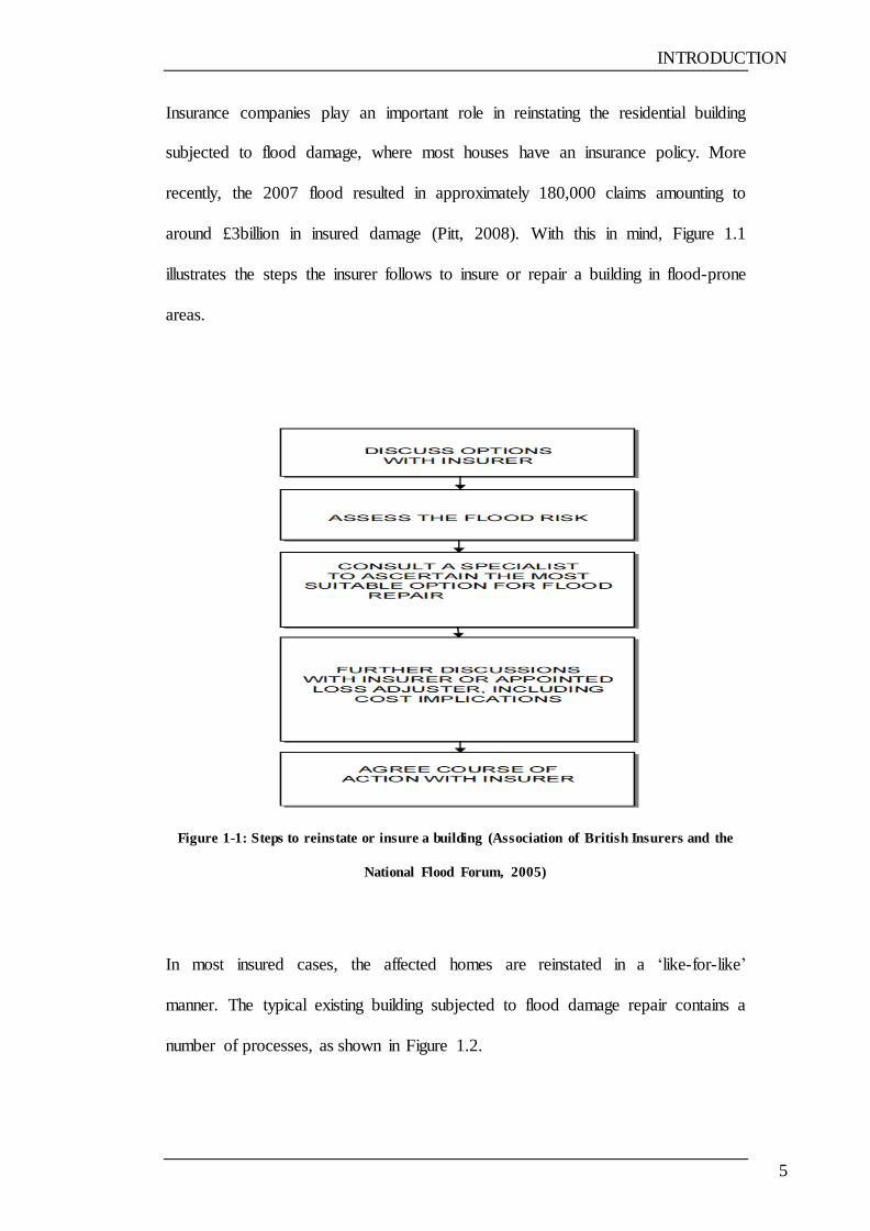
Insurance companies play an important role in reinstating the residential building
subjected to flood damage, where most houses have an insurance policy. More
recently, the 2007 flood resulted in approximately 180,000 claims amounting to
around £3billion in insured damage (Pitt, 2008). With this in mind, Figure 1.1
illustrates the steps the insurer follows to insure or repair a building in flood-prone
areas.
Figure 1-1: Steps to reinstate or insure a building (Association of British Insurers and the
National Flood Forum, 2005)
In most insured cases, the affected homes are reinstated in a ‗like-for-like‘
manner. The typical existing building subjected to flood damage repair contains a
number of processes, as shown in Figure 1.2.
INTRODUCTION
6
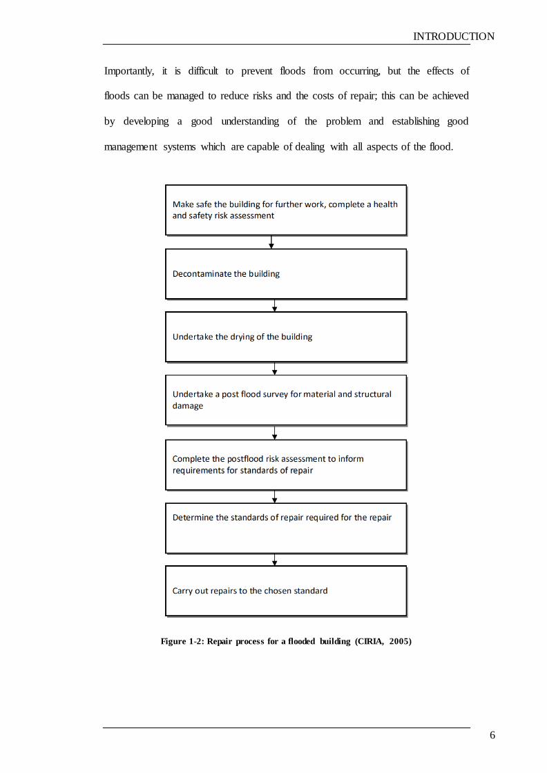
Importantly, it is difficult to prevent floods from occurring, but the effects of
floods can be managed to reduce risks and the costs of repair; this can be achieved
by developing a good understanding of the problem and establishing good
management systems which are capable of dealing with all aspects of the flood.
Figure 1-2: Repair process for a flooded building (CIRIA, 2005)
INTRODUCTION
7
A number of surveys, case studies, and papers have indicated the difficulties
experienced in managing flood events and their subsequent results. This
highlights the need for a more coordinated approach to the problem, and also that
the literature describing how to repair flood damaged properties are very general
and need update (Wordsworth & Bithell, 2004; Nicholas, Holt & Proverbs, 2001;
DCLG, 2010; Environment, Food and Rural Affairs Committee 2008).
A review of the literature has highlighted an increased need for professional
advice for both individuals and developers on designing for floods (Wynn, 2002).
In addition, definitive guidance for repairing flood damaged buildings is needed in
order to minimise variations in subsequent repair and reinstatement works
(Soetanto & Proverbs, 2004; DCLG, 2010; ABI, 2010).
In the Carlisle flood of 2005, Hendy (2006) mentioned the following points
regarding the service provided to the homeowner by the insurer:
I. The low level of proficiency; and
II. Neighbours with similar properties and policies repair works done to their
properties.
Woodhead (2008) mentioned that the level of confidence of homeowners
decreases with reinstatement process time, as shown in Figure 1.3. Pitt (2008)
further states that homeowners were dissatisfied with the recovery service
provided by the insurance companies, simply because the repair processes took a
long time.

INTRODUCTION
8
It is clear that resilience can help to minimise the damage from floodwaters, and
also greatly reduces the timescale for recovery of a property (Broadbent, 2004;
ABI, 2003; DEFRA, 2008; ABI, 2006; Escarameia, Karanxha, and Tagg, 2007).
A study by ABI and the Building Research Establishment (BRE) states that
resistance and resilience measures can, in many cases, mean that essential services
can be maintained during the flood event; flooded buildings can be re-cleaned,
dried and restored within a short time and a minimum of disruption (ABI, 2002;
ABI,2006).
Figure 1-3: Level of homeowner satisfaction with respect to reinstatement time (Woodhead,
2008)
Pitt (2008) recommends that the Building Regulations should be revised to ensure
that all new buildings or refurbished building in flood-risk areas are flood-
resistant or resilient. He also adds that all local authorities should extend
INTRODUCTION
9
eligibility for home improvement grants and loans so as to include flood
resistance and resilience products for properties in risk flood areas.
In July 2004, the Government launched the ‗Making Space for Water‘
consultation exercise, which seeks views on a broad range of flood and coastal
erosion risk management issues in an attempt to inform the development of a new
strategy. Responses on flood resilience and resistance from the consultation urged
the government to (OST 2004):
a) Encourage the incorporation of suitable flood resilience and resistance
measures in new and existing buildings;
b) Include flood resilience measures in the new code for buildings;
c) Consider financial incentives for the adoption of flood resilience measures
in the existing properties; and
d) Improve the quality of advice on flood resilience and resistance to the
homeowners of properties, and to involve and train builders and surveyors
to achieve this goal.
DEFRA made a £500,000 grant available for the implementation of the pilot
scheme of property-level resistance and/or resilience measures. The aim was to
investigate approaches and to accordingly assess the implementation and
evaluation of potential take-up by property owners (Defra, July, 2008).
The comprehensive Pitt review following the severe flood in the United Kingdom
in 2007—during which time 55,000 properties were affected by floods—
INTRODUCTION
10
contained 92 recommendations, including (Pitt, 2008; EA,2011; Rhodes, and
Proverbs, 2008):
a) The building regulations should be revised to ensure that all new buildings
or refurbished buildings in flood-risk areas are flood-resistant or resilient;
and
b) All local authorities should broaden eligibility for home improvement
loans and grants so as to consider flood resistance and resilience products
for properties in the high risk flood-prone areas.
1.3 RESEARCH AIMS AND OBJECTIVES
The aim of this research is to investigate the vulnerability of residential buildings
to flooding damage, and to accordingly develop an intelligent system for assessing
the vulnerability of residential buildings to flooding damage, and recommend
remedial measures. In order to achieve the above aim, the following are the main
objectives of the research:
To review the risk exposure of residential buildings to flood damage—
especially in the UK;
To review recent research developments in the vulnerability assessment
and remediation of residential buildings subjected to flooding;
To develop a method to assess the vulnerability of residential building
subjected to flood damage;
To undertake detailed case studies with a view to establishing current
industry practice, identifying opportunities for improvement, and
establishing end-user requirements;
INTRODUCTION
11
To develop a framework and functional specification for an intelligent
approach to the vulnerability assessment and remediation of residential
buildings subject to flood damage; and
To implement and evaluate a prototype system based on the functional
specification developed above and using test cases from industry.
1.4 PURPOSE OF DEVELOPING THE KNOWLEDGE BASE SYSTEM
The use of an intelligent system for the assessment and remediation of buildings
subjected to flooding and subsidence damage can facilitate the management of
this problem. Such a system can provide guidance for the assessment of
vulnerability and the repair of flood damaged residential buildings, and could also
save time and money through the use of the advantage and the benefits of
knowldge base systems. The management of flood damage would also gain
numerous benefits and improvements through:
I. Knowledge, which can be transferred easily to the largest number
of stakeholders in a short time. This will help to train younger
engineers working in the field of flood damage management, and
accordingly increase the level of rehabilitation;
II. Reductions in the time required for decision-making, where the
information is organised, easily and rapidly accessible;
III. The ability to compare different remediation alternatives easily and
in a short time;
IV. Laptop system installation, which will help to identify the problem
and make decisions on-site;
V. Less expensive, thereby helping to reduce costs.
INTRODUCTION
12
The intelligent system proposed in this research has the aim of achieving the
following objectives:
To assess and evaluate the vulnerability of buildings to flood damage, with
consideration to factors contributing to building flood damage;
To assist in the selection of repair methods and procedures to be followed
when dealing with flooded buildings, as based on the degree of
vulnerability to flood damage; and
To aid in the selection of suitable flood damage reduction options by
introducing resilience options as this will reduce the cost of future damage
repair. The resilience remediation options are only recommended when the
vulnerability of buildings to flood damage is high.
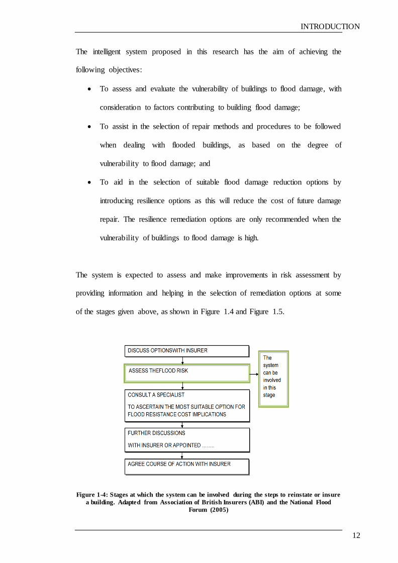
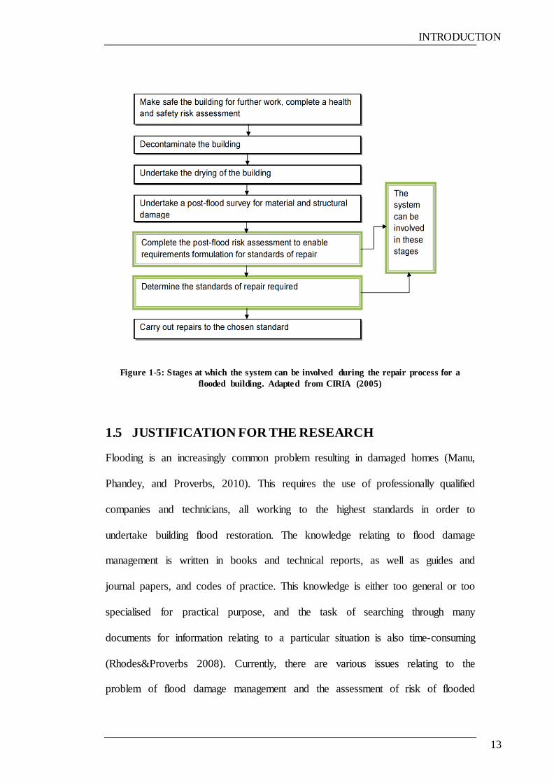
The system is expected to assess and make improvements in risk assessment by
providing information and helping in the selection of remediation options at some
of the stages given above, as shown in Figure 1.4 and Figure 1.5.
Figure 1-4: Stages at which the system can be involved during the steps to reinstate or insure
a building. Adapted from Association of British Insurers (ABI) and the National Flood
Forum (2005)
INTRODUCTION
13
Figure 1-5: Stages at which the system can be involved during the repair process for a
flooded building. Adapted from CIRIA (2005)
1.5 JUSTIFICATION FOR THE RESEARCH
Flooding is an increasingly common problem resulting in damaged homes (Manu,
Phandey, and Proverbs, 2010). This requires the use of professionally qualified
companies and technicians, all working to the highest standards in order to
undertake building flood restoration. The knowledge relating to flood damage
management is written in books and technical reports, as well as guides and
journal papers, and codes of practice. This knowledge is either too general or too
specialised for practical purpose, and the task of searching through many
documents for information relating to a particular situation is also time-consuming
(Rhodes&Proverbs 2008). Currently, there are various issues relating to the
problem of flood damage management and the assessment of risk of flooded
INTRODUCTION
14
building for insurance purposes, which need to be dealt with. Mainly, insurance
cover is not related to flood risk, and it is also clear that there is a need to establish
repair standards. Moreover, there is a need for a system which helps to estimate
the vulnerability of building to flood damage, and that also contains relevant
information, which will help speed and standardised developing of repair
strategies, and assessments in evaluate the risk of buildings due to flood. In
addition, the knowledge acquired can be very useful, and may act as a training
tool for the new people coming into the industry.
To cope with the issues mentioned above, there is the need for an organised and
concise system to evaluate the vulnerability of residential buildings subjected to
flood damage, which should comprise all information relating to repair methods
and the procedure of remediation of buildings damaged by flood, which lead to
standardised and speed flooded building repair. Notably, such a system should
also help in establishing the basis for flooded residential building risk assessment
and repair process.
In addition, the system should also include resilience options as one other repair
option could reduce time, costs and repairs in the case of the building flooded in
the future (Escarameia,Karanxha,and Tagg,2007; Department for Environment
Food and Rural Affairs ,2008). In order to satisfy these needs, it is therefore
essential to carry out this research.
INTRODUCTION
15
1.6 RESEARCH METHODS
Figures 1.1 illustrates the research methods used to achieve the specific objectives
of the research. A brief description of the research methods used is given in this
section. The detailed research methodology is presented in Chapter 2.
1. Literature Review: The extensive literature review focused on three major
subjects: first, reviewing vulnerability assessment to understand the
concept of vulnerability and the methods of vulnerability assessment;
second, flood damage management so as to gain an understanding of all
issues relating to flood and the flood damage of residential buildings; and
thirdly, review the Knowledge-Based System in general, and its
applications in civil engineering in particular. Notably, the literature
review on these three topics provides a theoretical background and forms
the basis for continuing further into the research. Importantly, the review
of literature was achieved through several sources, including publications
from several professional bodies, participation at workshops, seminars to
interact with other researchers and professionals in similar research areas,
the use of the Loughborough University library to assess reports, theses,
journals and conference papers relating to the subject, and relevant internet
searches.
2. Knowledge Acquisition: The process involves capturing and transforming
appropriate knowledge from experts in the related field into some
manageable form in an attempt to develop a knowledge-based system
which can assess the vulnerability of building subjected to flood damage
and help in selection of repair options. In addition, a method to assess the
INTRODUCTION
16
vulnerability of buildings subjected to flood damage has been developed
through identifying the factors contributing to the vulnerability of
buildings subjected to flood damage based on the literature available, and
accordingly investigated through a questionnaire survey. Moreover, factor
weighting (rating) was then used to develop a simple model to determine
the vulnerability (refer to Chapter 3 and Chapter 4 of this thesis for further
details).
This research has utilised two postal surveys with the objective to
investigate the factors that contribute to the vulnerability of buildings
subjected to flood damage, and remediation options. Knowledge acquired
for the prototype system using a number of different techniques and
methods, including review of literature and survey questionnaire. The first
questionnaire was applied to help in rating factors assigned based on the
literature, and then accordingly utilised in order to develop the model so as
to determine the vulnerability. The second questionnaire was used to
investigate the existing repair options. In addition, other sources were also
used to validate and thereby gain a deeper understanding of the knowledge
acquired each time, including documents, interviews and discussion with
experts during the workshops and seminars.
In addition The Document Processing knowledge acquisition method were used
which is considered as the most important and reliable approach (Castellanos,
Albiter, Hernandez, and Barrera (2011).
INTRODUCTION
17
3. Prototype Development: The development of the proposed knowledge-
based system was based on the results captured from the knowledge
acquisition process. Rapid prototyping methodology was used in the
prototype development.
4. Evaluation: The completed prototype was evaluated following the
development process in order to assess functionality and usability. The
evaluators were drawn from flood damage repair industry experts,
researcher and academic. The prototype was demonstrated to the
evaluators, who were then asked to use the system. At the end of each
evaluation process, the evaluators were asked to complete a questionnaire
which assessed the prototype from various perspectives.
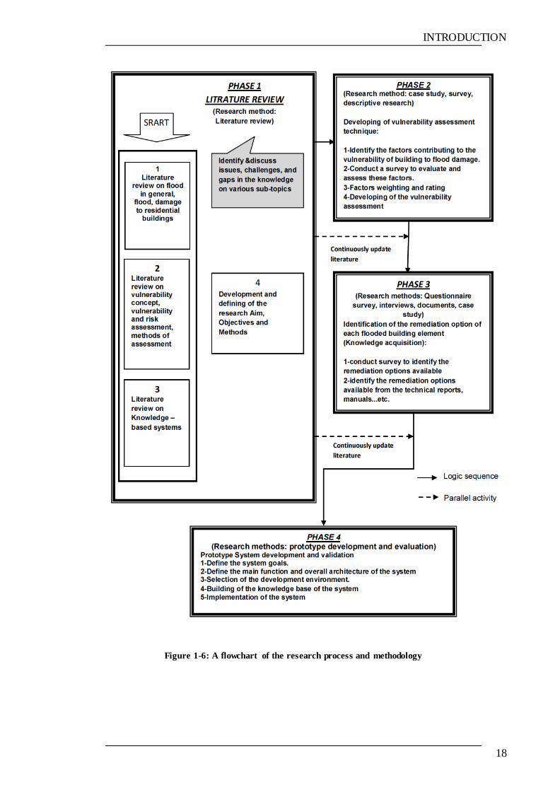
A flowchart summarising the research process and methods adopted is presented
in Figure 1.6, with further information concerning the methodological issues
presented in subsequent chapters.
INTRODUCTION
18
Figure 1-6: A flowchart of the research process and methodology

RESEARCH METHODOLOGY
19
CHAPTER 2 RESEARCH METHODOLOGY
2.1 INTRODUCTION
Research methodology can be described as the activities carried out by researchers
in the investigation of various matters, dealing specifically with the methods of
data collection, analysis and interpretation. This chapter will describe different
research methodologies, and subsequently focus on the research methodology
used in this research.
2.2 REVIEW OF RESEARCH METHODS
Research methods can be classified in a number of ways. One of the most
common methods of classification is into quantitative and qualitative research and
a combination of the two (Breach, 2009):
I. Quantitative methods of research: this method of research deals
with the investigation of problems that can be represented in terms
of numbers. Examples of quantitative methods applied in
engineering and science normally involve some or all of the
following:
o creating mathematical models to investigate theories and
hypotheses
o designing instruments
o developing methods of measurement
o collecting numerical data
o experiments with controls
o changing variables and appraising the results.
RESEARCH METHODOLOGY
20
II. Qualitative research methods: these methods deal with ideas,
opinions, meanings and perceptions. The methods of qualitative
research are direct observation by the researcher, questionnaires,
and interviews, as well as documentary review.
III. Combined (qualitative and quantitative): simply a combination of
qualitative and quantitative methods, where both are used at the
same time.
2.2.1 QUANTITATIVE RESEARCH
Quantitative research can be defined as ‗an inquiry into a social or human
problem, based on testing a hypothesis or theory composed of variables, measured
with numbers, and analysed with statistical procedures to determine whether the
hypothesis or theory holds true‘ (Creswell, 2009). There are two main types of
quantitative research method: experiments and surveys. A brief note on each of
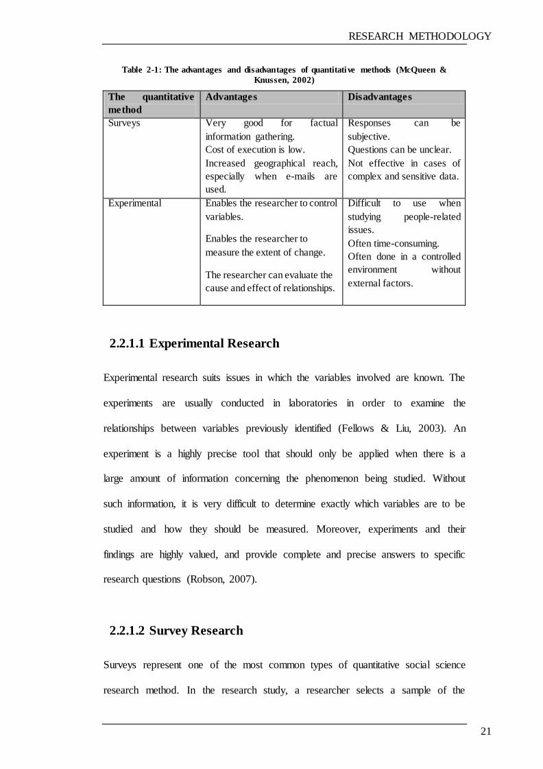
these two methods is presented in the next sections. Table 2.1 describes both the
advantages and disadvantages of using these methods.
RESEARCH METHODOLOGY
21
Table 2-1: The advantages and disadvantages of quantitative methods (McQueen &
Knussen, 2002)
The quantitative
method
Advantages Disadvantages
Surveys Very good for factual
information gathering.
Cost of execution is low.
Increased geographical reach,
especially when e-mails are
used.
Responses can be
subjective.
Questions can be unclear.
Not effective in cases of
complex and sensitive data.
Experimental
Enables the researcher to control
variables.
Enables the researcher to
measure the extent of change.
The researcher can evaluate the
cause and effect of relationships.
Difficult to use when
studying people-related
issues.
Often time-consuming.
Often done in a controlled
environment without
external factors.
2.2.1.1 Experimental Research
Experimental research suits issues in which the variables involved are known. The
experiments are usually conducted in laboratories in order to examine the
relationships between variables previously identified (Fellows & Liu, 2003). An
experiment is a highly precise tool that should only be applied when there is a
large amount of information concerning the phenomenon being studied. Without
such information, it is very difficult to determine exactly which variables are to be
studied and how they should be measured. Moreover, experiments and their
findings are highly valued, and provide complete and precise answers to specific
research questions (Robson, 2007).
2.2.1.2 Survey Research
Surveys represent one of the most common types of quantitative social science
research method. In the research study, a researcher selects a sample of the
RESEARCH METHODOLOGY
22
population, and issues a standardised questionnaire to the sample. The survey can
be conducted via a written document to be completed by the persons being
surveyed (or it can be issued via the Internet), a face-to-face interview, or a
telephone interview. Surveys make it possible to obtain information from a large
or small number of people. A survey can be carried out with the aim of collecting
data from a group of people and/or on a subject area by various methods including
mail and interviews.
A survey typically involves obtaining answers to a number of standard questions
from a carefully selected group of people (Robson, 2007). Survey methods vary
from highly structured questionnaires to unstructured interviews (Fellows & Liu,
2003).
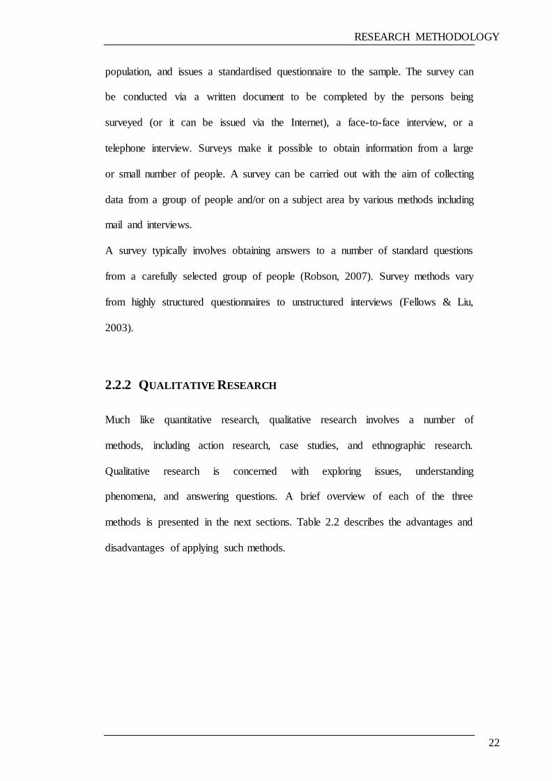
2.2.2 QUALITATIVE RESEARCH
Much like quantitative research, qualitative research involves a number of
methods, including action research, case studies, and ethnographic research.
Qualitative research is concerned with exploring issues, understanding
phenomena, and answering questions. A brief overview of each of the three
methods is presented in the next sections. Table 2.2 describes the advantages and
disadvantages of applying such methods.

RESEARCH METHODOLOGY
23
Table 2-2: Advantages and disadvantages of qualitative methods (McQueen & Knussen,
2002)
The qualitative method Advantages Disadvantages
Action research A collaborative approach
which gives an active role to
participants, hence a more
democratic form of research
than most approaches.
It is particularly suitable for
practitioner–researchers,
contributing to their
professional and personal
development.
If successful, it can initiate a
continuing cycle of
development.
The involved collaborative stance
required is difficult for a novice
researcher.
The shared ownership of the research
processes between researchers and
participants can lead to problems,
particularly as regards completion of
the project on time.
Active co-operation by participants is
essential, but is difficult to achieve as
it takes place in the work setting
where there can be conflicting
demands.
Case studies Studying a single case (or a
small number of cases) gives
the opportunity to carry out a
study in depth, which can
capture complexities,
relationships and processes.
It strongly encourages the use
of multiple methods of
collecting data, and of
multiple data sources.
It can be used for a wide
variety of research purposes
and for widely different types
of cases.
Case studies typically seek to focus
on situations as they occur naturally,
and hence observer effects caused by
the presence of the researchers can be
problematic.
The flexible nature of case study
design means that you have to be
prepared to modify your approach,
depending on the results of your
involvement. It can be difficult to
keep to deadlines.
Ethnographic surveys They rely upon direct
observation and do not call for
other specialized data
collection methods.
They are particularly suitable
for studies focusing on how
members of a culture see
events.
They can be very involving
and interesting.
It can be very difficult and confusing
for novice researchers to come to
terms with their participant observer
role.
The skills needed to understand what
is going on in a strange situation,
including decisions on the choice of
informants, may need considerable
experience to acquire.
There are problems of generalizability
of findings similar to those with case
studies.
RESEARCH METHODOLOGY
24
2.2.2.1 Action Research
Action research is an approach involving active participation by the researcher in
a situation or practice with the aim of evaluating the problem and finding a
solution or improvement. Action research can adopt a variety of data collection
methods, depending on the type of research question the researcher seeks to
answer. A great deal of emphasis is directed to the quality of the research data—
usually in the form of words—obtained from relatively unstructured interviews or
observations of participants (Fellows & Liu, 2003; Robson, 2007).
2.2.2.2 Case Studies
Case studies focus on the development and in-depth analysis of the case or a small
number of cases. The cases are selected because they are important or interesting.
Furthermore, case studies adopt a variety of methods of data collection, including
interviews and observations. They are sometimes based purely on documentary
sources. In such cases, it is advisable to have a set of documents of different types
for analysis (documentary analysis) (Robson, 2007).
2.2.2.3 Ethnographic Research
Ethnography is a social science research method which can be defined as ‗the art
and science of describing a group or culture‘ (Fetterman, 1998). Ethnographic
research applies three kinds of data collection method: interviews, observation and
documents. The group can be a team or an organisation, and ‗culture‘ can refer to
that of the organisation. Researchers conducting ethnographic assessments of
organisational culture do so through the monitoring and recording of behaviour
RESEARCH METHODOLOGY
25
within the organisation over an extended period of time (Somekh & Lewin, 2005).
Moreover, ethnographers detail the daily routine of people in the group.
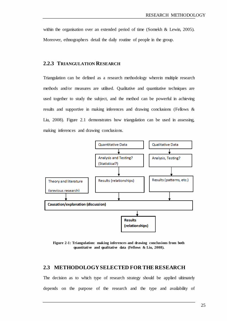
2.2.3 TRIANGULATION RESEARCH
Triangulation can be defined as a research methodology wherein multiple research
methods and/or measures are utilised. Qualitative and quantitative techniques are
used together to study the subject, and the method can be powerful in achieving
results and supportive in making inferences and drawing conclusions (Fellows &
Liu, 2008). Figure 2.1 demonstrates how triangulation can be used in assessing,
making inferences and drawing conclusions.
Figure 2-1: Triangulation: making inferences and drawing conclusions from both
quantitative and qualitative data (Fellows & Liu, 2008).
2.3 METHODOLOGY SELECTED FOR THE RESEARCH
The decision as to which type of research strategy should be applied ultimately
depends on the purpose of the research and the type and availability of
RESEARCH METHODOLOGY
26
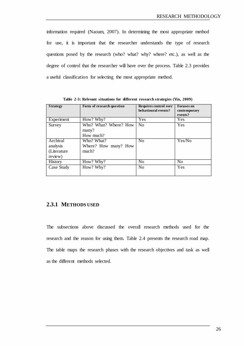
information required (Naoum, 2007). In determining the most appropriate method
for use, it is important that the researcher understands the type of research
questions posed by the research (who? what? why? where? etc.), as well as the
degree of control that the researcher will have over the process. Table 2.3 provides
a useful classification for selecting the most appropriate method.
Table 2-3: Relevant situations for different research strategies (Yin, 2009)
Strategy Form of research question Requires control over
behavioural events?
Focuses on
contemporary
events?
Experiment How? Why? Yes Yes Survey Who? What? Where? How
many? How much?
No Yes
Archival analysis (Literature review)
Who? What? Where? How many? How much?
No Yes/No
History How? Why? No No Case Study
How? Why? No Yes
2.3.1 METHODS USED
The subsections above discussed the overall research methods used for the
research and the reason for using them. Table 2.4 presents the research road map.
The table maps the research phases with the research objectives and task as well
as the different methods selected.
RESEARCH METHODOLOGY
27
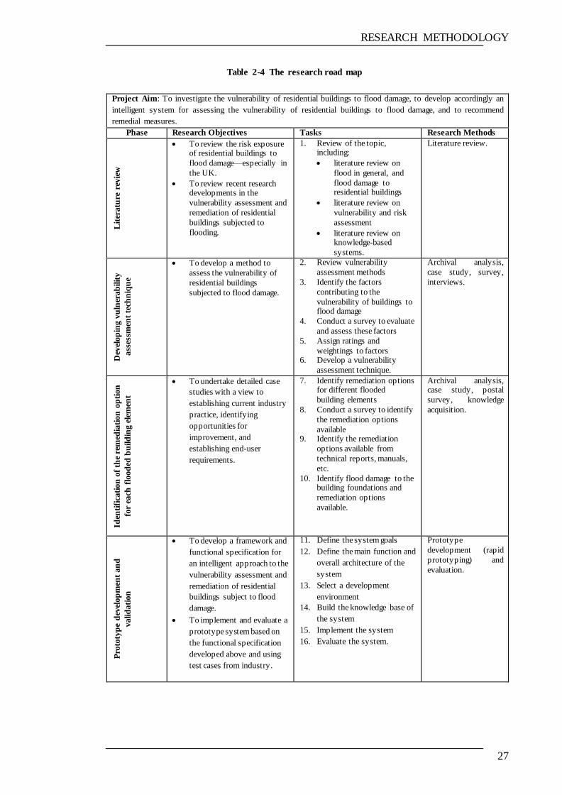
Table 2-4 The research road map
Project Aim: To investigate the vulnerability of residential buildings to flood damage, to develop accordingly an
intelligent system for assessing the vulnerability of residential buildings to flood damage, and to recommend
remedial measures.
Phase Research Objectives Tasks Research Methods
Lit
eratu
re r
evie
w
To review the risk exposure of residential buildings to
flood damage—especially in
the UK.
To review recent research developments in the
vulnerability assessment and
remediation of residential
buildings subjected to
flooding.
1. Review of the topic, including:
literature review on
flood in general, and
flood damage to residential buildings
literature review on
vulnerability and risk
assessment
literature review on knowledge-based
systems.
Literature review.
Dev
elop
ing v
uln
erab
ilit
y
ass
essm
ent
tech
niq
ue
To develop a method to
assess the vulnerability of
residential buildings
subjected to flood damage.
2. Review vulnerability
assessment methods
3. Identify the factors
contributing to the
vulnerability of buildings to flood damage
4. Conduct a survey to evaluate
and assess these factors
5. Assign ratings and
weightings to factors 6. Develop a vulnerability
assessment technique.
Archival analysis,
case study, survey,
interviews.
Iden
tifi
cati
on
of
the
rem
edia
tion
op
tion
for
each
flo
od
ed b
uild
ing e
lem
ent
To undertake detailed case
studies with a view to
establishing current industry
practice, identifying
opportunities for
improvement, and
establishing end-user
requirements.
7. Identify remediation options for different flooded
building elements
8. Conduct a survey to identify
the remediation options
available 9. Identify the remediation
options available from
technical reports, manuals,
etc.
10. Identify flood damage to the building foundations and
remediation options
available.
Archival analysis, case study, postal
survey, knowledge
acquisition.
Pro
toty
pe
dev
elop
men
t an
d
valid
ati
on
To develop a framework and
functional specification for
an intelligent approach to the
vulnerability assessment and
remediation of residential
buildings subject to flood
damage.
To implement and evaluate a
prototype system based on
the functional specification
developed above and using
test cases from industry.
11. Define the system goals
12. Define the main function and
overall architecture of the
system
13. Select a development
environment
14. Build the knowledge base of
the system
15. Implement the system
16. Evaluate the system.
Prototype
development (rapid
prototyping) and
evaluation.
RESEARCH METHODOLOGY
28
2.3.2 LITERATURE REVIEW
Fink (2010) defines a literature review as ‗a systematic, explicit, comprehensive,
and reproducible method for identifying, evaluating and interpreting the existing
body of original work produced by researchers and scholars‘. Moreover, in the
view of Fink (2010), high quality literature reviews should base their findings on
evidence ascertained through experiments or controlled observation.
A review of the literature should be carried out widely and conclusively at all
stages of the study in an attempt to establish a solid foundation for the research
topic and to provide a basis for addressing the problems and achieving the
objectives of the research.
The main reasons for conducting a literature review, as highlighted by Neuman &
Lawrence (2003) and Fink (2010), include the following:
to clarify and explain the background of the subject of research
to identify gaps in the available literature and thereby indicate what will
add to the topic
to identify methods, ideas and information suitable for research
to identify experts who could assist in the interpretation of existing
literature and identify sources of unpublished information
to review previous works by others in this area
to identify effective research and development methods.
A literature review is the cheapest and effective method of collecting the existing
literature on the subject matter. In this research, an intensive review of the

RESEARCH METHODOLOGY
29
literature has been carried out in order to investigate the residential building flood
damage problem. This involved a detailed investigation of three topics, including:
I. Vulnerability and vulnerability assessment: definition and concepts of
vulnerability, vulnerability assessment, and methods of vulnerability
assessment specially related to geohazard risks, such as landslides and
earthquakes.
II. Issues relating to floods and flood damage caused to residential buildings:
including types and characteristics of flood, types and characteristics of
buildings in the UK, flood damage, building materials, and the effects of
flooding. Also reviewed were different remediation methods for buildings
and building elements subjected to flood damage.
III. Knowledge-based systems: including concepts, types, and advantages,
methods of development, applications, and previous systems developed in
the field of civil engineering.
A number of procedures were carried out in order to conduct the literature review,
including: defining the research topic, identifying the sources of information,
keeping records, reading, and note-taking.
2.3.3 CASE STUDIES
A case study should involve extensive data collection as a means of providing a
broad understanding of the domain being studied. This is the preferred strategy
when ‗how‘, ‗who‘, ‗why‘ or ‗what‘ questions are being posed, or when the focus
is on contemporary real-life phenomena. Case studies are selected in an attempt to
RESEARCH METHODOLOGY
30
develop knowledge concerning the key topics of the research, which in this
instance are: flood damage caused to residential buildings and their vulnerability
assessment, and establishing a relationship between these so that the selection of
the proper way of repairing these buildings can be based on their degree of
vulnerability to flood damage, thereby reducing future costs. The case study
method was selected as it provides an in-depth analysis of a specific domain
(Naum, 2007). In this regard, the case study method helps in terms of providing
an understanding of a difficult topic or subject, and can therefore extend
knowledge or add strength to what is already known from existing research
(Cohen, Manion, and Morrison, 2007). In addition, Anderson et al. (2005) believe
that the case study strategy can contribute appropriately at any level of knowledge
development. Moreover, the case study also provides a detailed investigation of
variables relevant to the subject under study (Key, 1997). A case study may
combine a variety of data collection methods and research strategies (Fellows &
Liu, 2008). The case study approach was used in this research to develop the
vulnerability assessment model, and to establish a framework for remediation
options strategies.
In this research the case study approach was used for tasks 3, 7, 9, and 10 (see
Table 2.3) to gather data from many different sources, including documents,
experts and companies in the field of flooded buildings damage management.
RESEARCH METHODOLOGY
31
2.3.4 KNOWLEDGE ACQUISITION
Many techniques have been developed to assist in obtaining knowledge from
experts. This process is referred to as the development of knowledge or
knowledge acquisition (KA). Knowledge acquisition can be defined as the transfer
and transformation or capturing of potential problem-solving expertise from one
or more knowledge sources to a computer program (Buchanan et al., 1983;
Milton, 2007).
In addition, there are several different sources of knowledge acquisition (Turban
& Aronson, 2001), including:
documented (books, manuals, technical reports, etc.)
undocumented (from experts or professionals in the field)
databases
the Internet.
Moreover, there are a number of factors which should be kept in mind when
running a project to acquire knowledge (Milton, 2007):
The end product must be useful to the end-users.
In order to be useful, the knowledge should be of high quality, correct,
relevant, and stored in a structured manner.
The project must be run in an effective way so as to use most of the
available resources.
In this research, the knowledge acquisition process involved collecting as much
information as possible from different sources which might be needed for the
RESEARCH METHODOLOGY
32
objectives of this research. The knowledge captured was mainly derived from
three sources: firstly, experts working in the field of flooded buildings damage
management (human experts); secondly, books, peer-reviewed journal and
conference papers, manuals and technical reports (documented sources); and
thirdly, a questionnaire survey. The focus was on gathering information which
met the purposes of this research, and was related to the following topics:
a) Factors affecting the vulnerability of residential buildings and the different
components affected by the flooding, as well as the materials used in the
buildings
b) Methods of repairing buildings exposed to flooding; the relationship
between the choice of methods and the vulnerability of the buildings and
their different components; and the use of methods and materials to reduce
the risk of flooding, and accordingly reduce the costs of repair in the
future.
According to Kendal & Creen (2007), printed sources and the Internet can be very
useful for acquiring knowledge. In the specific context of knowledge engineering,
with particular reference to the acquisition of knowledge in a certain area, detailed
technical information, case studies and textbooks demonstrate high value. With
this in mind, it is important that the engineer utilises knowledge from such
sources.
During the knowledge acquisition phase, the knowledge engineer utilises
techniques and tools such as those mentioned above in order to gain implicit
knowledge from professionals in the discipline (Milton, 2007). Turban & Aronson
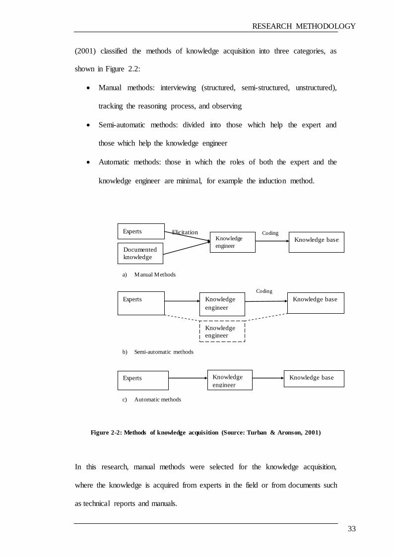
RESEARCH METHODOLOGY
33
(2001) classified the methods of knowledge acquisition into three categories, as
shown in Figure 2.2:
Manual methods: interviewing (structured, semi-structured, unstructured),
tracking the reasoning process, and observing
Semi-automatic methods: divided into those which help the expert and
those which help the knowledge engineer
Automatic methods: those in which the roles of both the expert and the
knowledge engineer are minimal, for example the induction method.
a) Manual Methods
b) Semi-automatic methods
c) Automatic methods
Figure 2-2: Methods of knowledge acquisition (Source: Turban & Aronson, 2001)
In this research, manual methods were selected for the knowledge acquisition,
where the knowledge is acquired from experts in the field or from documents such
as technical reports and manuals.
Experts Knowledge
engineer Documented
knowledge
Knowledge base Coding Elicitation
Knowledge
engineer
Experts Knowledge base
Knowledge
engineer
Coding
Knowledge
engineer
Knowledge base Experts
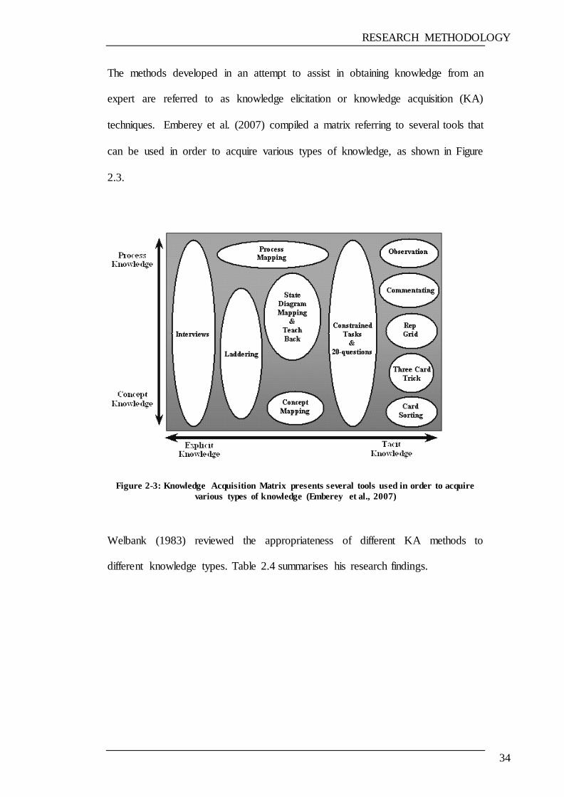
RESEARCH METHODOLOGY
34
The methods developed in an attempt to assist in obtaining knowledge from an
expert are referred to as knowledge elicitation or knowledge acquisition (KA)
techniques. Emberey et al. (2007) compiled a matrix referring to several tools that
can be used in order to acquire various types of knowledge, as shown in Figure
2.3.
Figure 2-3: Knowledge Acquisition Matrix presents several tools used in order to acquire
various types of knowledge (Emberey et al., 2007)
Welbank (1983) reviewed the appropriateness of different KA methods to
different knowledge types. Table 2.4 summarises his research findings.
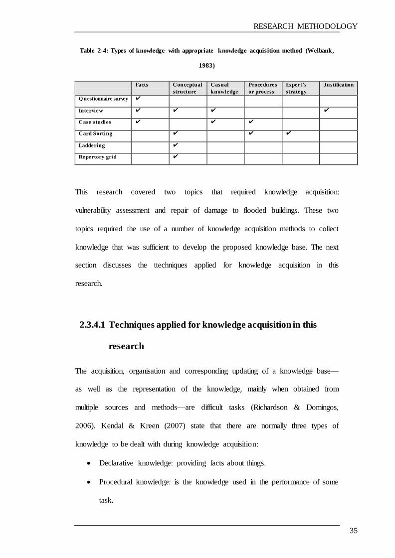
RESEARCH METHODOLOGY
35
Table 2-4: Types of knowledge with appropriate knowledge acquisition method (Welbank,
1983)
Facts Conceptual
structure
Casual
knowledge
Procedures
or process
Expert’s
strategy
Justification
Q uestionnaire survey ✔
Interview ✔ ✔ ✔ ✔
Case studies ✔ ✔ ✔
Card Sorting ✔ ✔ ✔
Laddering ✔
Repertory grid ✔
This research covered two topics that required knowledge acquisition:
vulnerability assessment and repair of damage to flooded buildings. These two
topics required the use of a number of knowledge acquisition methods to collect
knowledge that was sufficient to develop the proposed knowledge base. The next
section discusses the ttechniques applied for knowledge acquisition in this
research.
2.3.4.1 Techniques applied for knowledge acquisition in this
research
The acquisition, organisation and corresponding updating of a knowledge base—
as well as the representation of the knowledge, mainly when obtained from
multiple sources and methods—are difficult tasks (Richardson & Domingos,
2006). Kendal & Kreen (2007) state that there are normally three types of
knowledge to be dealt with during knowledge acquisition:
Declarative knowledge: providing facts about things.
Procedural knowledge: is the knowledge used in the performance of some
task.
RESEARCH METHODOLOGY
36
Meta-knowledge: knowledge about knowledge, which helps us to learn
how experts use knowledge to make decisions.
The main sources of knowledge used in this research include:
Expert opinion: in this research, expert opinion was ascertained in various
different ways: indirectly, during workshops and seminars, when
discussing or presenting ideas or problems relating to the research topic;
directly, by asking a question or introducing an idea or issue, and allowing
the expert to give their opinion or comments; and through using survey
questionnaires.
The library database: access to a wide range of information sources,
including full-text journals, books, and electronic books, images, and
statistical data related to the research area.
Historical data: information relating to previous flood events, which was
requested from the Environment Agency (EA), the Construction Industry
Research and Information Association (CIRIA), and the British Insurance
Association (BIA).
Codes of Practice: used as a source of repair methods to be included in the
knowledge base of the prototype system.
Standard engineering procedures: standards relating to the methods or
materials of repair, identified by their codes and numbers, given to the user
for use if required. e.g. the British Standards which used in this research.
Experimental data: results of experiments carried out by other researchers
or organisations studying the effects of floodwater on different building
materials or building structures, which were subsequently used in the

RESEARCH METHODOLOGY
37
evaluation and rating of factors relating to building materials to identify
the materials susceptible to damage by floodwater.
Technical literature including:
text books
journals
manuals
technical reports.
These materials were used to identify the factors adopted in vulnerability
assessment, remediation options, damage caused by flood, building
materials, knowledge base systems, and standards related to the research.
The Internet: used to access information and knowledge related to the
topic from different sources, including organisation websites.
The knowledge acquisition techniques used in this research for developing the
prototype system comprised a combination of methods, as illustrated below.
Questionnaire survey:
A questionnaire survey is a tool of scientific research which is widely used to
collect data relating to a particular topic or research problem. Two questionnaires
were developed for the purpose of this research. The questionnaires were
organised to obtain information relating to the following aspects of the research:
Factors affecting vulnerability of buildings to flood damage: Following the
identification of those factors believed to contribute to the vulnerability of
buildings to flood damage, as based on the literature review, a survey was
conducted in order to investigate these factors and to identify their relative
importance in terms of their contribution to the vulnerability of buildings
RESEARCH METHODOLOGY
38
to flood damage; and to identify any other factors that might not have been
apparent from the literature review.
The repair of flood-damaged buildings: Data were collected from the
literature review on the methods and options used for the maintenance of
buildings exposed to flooding. The questionnaire was applied with the aim
of identifying the various different methods of remediation. Some flood
characteristics—mainly flood depth—were based on previous cases of
flooding and past experience. Also of interest were any materials or other
options that can be used during the repair of flood damaged buildings.
The survey questionnaire (cross-sectional) method was adopted for the collection
of required information owing to its advantages in being economical and offering
rapid results in data collection. Both an Internet survey via email and a postal
survey were carried out because of their low cost and their effectiveness. In
addition, the questionnaires were sent to a number of contractors and experts in
the field of flood damage management, or otherwise handed out in person during
workshops attended. The postal and email addresses of the contractors were
obtained by contacting various different organisations, such as The Royal
Institution of Chartered Surveyors (RICS), The Association of British Insurers
(ABI) and the Environment Agency (EA), or were otherwise collected in person
during the workshops.
Figure 2.4 illustrates various types of survey question. Rating questions were used
to investigate the factors affecting buildings‘ vulnerability to flood damage. The
aim was to determine the relative importance of each factor in contributing to

RESEARCH METHODOLOGY
39
vulnerability to flood damage (more details are given in Chapter 3). A copy of the
survey is shown in Appendix A.
Partial open-ended questions (multiple-choice with other options) were used in the
survey on the repair of flood-damaged buildings so as to give the participants the
opportunity to add any further remediation options. A copy of the survey is shown
in Appendix B.
Table 2-5: Types of survey question
Question
Type
Uses Advantages Disadvantages
Open-
ended
(essay or
short-
answer)
Discover relevant
issues
Obtain a full range of
responses
Explore respondents‘
views in depth
Identifies issues most
relevant to
respondents
Generates new ideas
about topic
Clarifies respondents‘
positions
Provides detail and
depth
Requires more time,
thought, and
communication skill
to complete
Requires time-
consuming data
entry
May generate
incomplete or
irrelevant data
Complicates data
summary and
analysis
Closed
(multiple-
choice or
yes/no)
Ask many questions
in a short time period
Assess learning or
attitudes when issues
are clear
Measure knowledge
or ability
Fast and easy to
complete
Enables automated
data entry
Facilitates data
analysis and summary
of data
Limits response
options
May omit a preferred
answer
Requires moderate
knowledge of the
topic to write
appropriate
questions and
responses
Lacks detail and
depth
Partial
open-
ended
(multiple-
choice
with
‗other‘
option)
Ask many questions
in a short time period
Assess learning or
attitudes when issues
are clear and
identifiable
Discover relevant
issues
Enables respondents
to create their own
response if choices do
not represent their
preferred response
Generates new ideas
about topic
Fast and easy to
complete
Requires moderate
knowledge of the
topic to write
appropriate
questions and
responses
Lacks detail and
depth
Complicates data
analysis and
summary
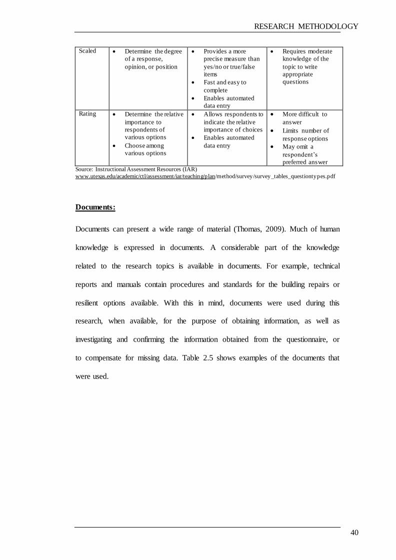
RESEARCH METHODOLOGY
40
Scaled
Determine the degree
of a response,
opinion, or position
Provides a more
precise measure than
yes/no or true/false
items
Fast and easy to
complete
Enables automated
data entry
Requires moderate
knowledge of the
topic to write
appropriate
questions
Rating
Determine the relative
importance to
respondents of
various options
Choose among
various options
Allows respondents to
indicate the relative
importance of choices
Enables automated
data entry
More difficult to
answer
Limits number of
response options
May omit a
respondent‘s
preferred answer Source: Instructional Assessment Resources (IAR)
www.utexas.edu/academic/ctl/assessment/iar/teaching/plan/method/survey/survey_tables_questiontypes.pdf
Documents:
Documents can present a wide range of material (Thomas, 2009). Much of human
knowledge is expressed in documents. A considerable part of the knowledge
related to the research topics is available in documents. For example, technical
reports and manuals contain procedures and standards for the building repairs or
resilient options available. With this in mind, documents were used during this
research, when available, for the purpose of obtaining information, as well as
investigating and confirming the information obtained from the questionnaire, or
to compensate for missing data. Table 2.5 shows examples of the documents that
were used.
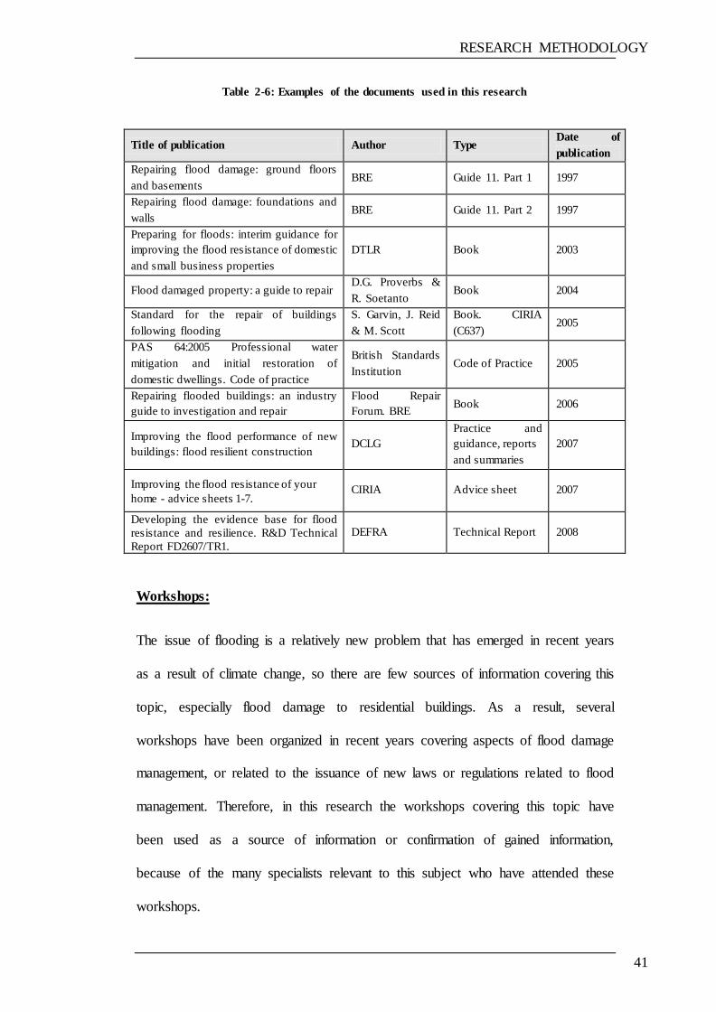
RESEARCH METHODOLOGY
41
Table 2-6: Examples of the documents used in this research
Workshops:
The issue of flooding is a relatively new problem that has emerged in recent years
as a result of climate change, so there are few sources of information covering this
topic, especially flood damage to residential buildings. As a result, several
workshops have been organized in recent years covering aspects of flood damage
management, or related to the issuance of new laws or regulations related to flood
management. Therefore, in this research the workshops covering this topic have
been used as a source of information or confirmation of gained information,
because of the many specialists relevant to this subject who have attended these
workshops.
Title of publication Author Type Date of
publication
Repairing flood damage: ground floors
and basements BRE Guide 11. Part 1 1997
Repairing flood damage: foundations and
walls BRE Guide 11. Part 2 1997
Preparing for floods: interim guidance for
improving the flood resistance of domestic
and small business properties
DTLR Book 2003
Flood damaged property: a guide to repair D.G. Proverbs &
R. Soetanto Book 2004
Standard for the repair of buildings
following flooding
S. Garvin, J. Reid
& M. Scott
Book. CIRIA
(C637) 2005
PAS 64:2005 Professional water
mitigation and initial restoration of
domestic dwellings. Code of practice
British Standards
Institution Code of Practice 2005
Repairing flooded buildings: an industry
guide to investigation and repair
Flood Repair
Forum. BRE Book 2006
Improving the flood performance of new
buildings: flood resilient construction DCLG
Practice and
guidance, reports
and summaries
2007
Improving the flood resistance of your
home - advice sheets 1-7. CIRIA Advice sheet 2007
Developing the evidence base for flood
resistance and resilience. R&D Technical
Report FD2607/TR1.
DEFRA Technical Report 2008
RESEARCH METHODOLOGY
42
Attendance and participation at a number of workshops was considered relevant
throughout the period of the research, for the following purposes:
increasing and improving the acquisition of information concerning the
subject matter
gaining views and ideas from discussions with experts
finding sources of information on the subject of the research
identifying the most recent developments, such as studies, technical
reports, regulations and technologies developed in relation to the research
problem
establishing specialists and experts in the subject of the research.
Workshops that have been attended are given below:
1. Critical examination of developments in flood resilience. HR Wallingford,
Oxfordshire, 27 March 2007.
2. Delivering flood risk management in new developments. The Arup
Campus, Solihull, West Midlands, 9 April 2008.
3. The impact of flooding on property owners. Birmingham, 8 May 2008.
4. Flood Repair Network. Anderson Strathern, Edinburgh, 9 October 2008.
5. Household flood resilience and protection – DEFRA consultation
workshops. DEFRA Innovation Centre, Reading, 24 October 2008.
6. Stemming the flow - managing flood risk in existing developments. The
Arup Campus, Solihull, West Midlands, 15 October 2009.

RESEARCH METHODOLOGY
43
In this research, the benefits gained from attendance at and participation in
workshops is as follows:
1. gaining information directly from the lectures presented or from audience
contributions
2. achieving a wider view and understanding of the topic
3. becoming acquainted with people and publications relating to the topic
4. gaining the opportunity to inquire about some aspects of information
which need to be clarified by specialists in this area (through unstructured
interviews)
5. gathering responses to the questionnaires that were distributed directly by
hand
6. identifying policies and regulations that will be developed and which are
related to the topic.
The unstructured interview technique was adopted during workshops in order
to gain knowledge from experts attending, in addition to the information
gained directly.
Various other techniques were also used, including codifying information and
classifying it for use, as well as conducting interviews with professionals who
attended the workshops. In addition, the database of the model was updated and
developed each time new information was obtained from the workshops.
2.3.5 PROTOTYPE DEVELOPMENT
The final objective of this research was to implement and evaluate a prototype
system, which is the most important element of the methodology used. A rapid
prototyping methodology was applied with the objective of developing the
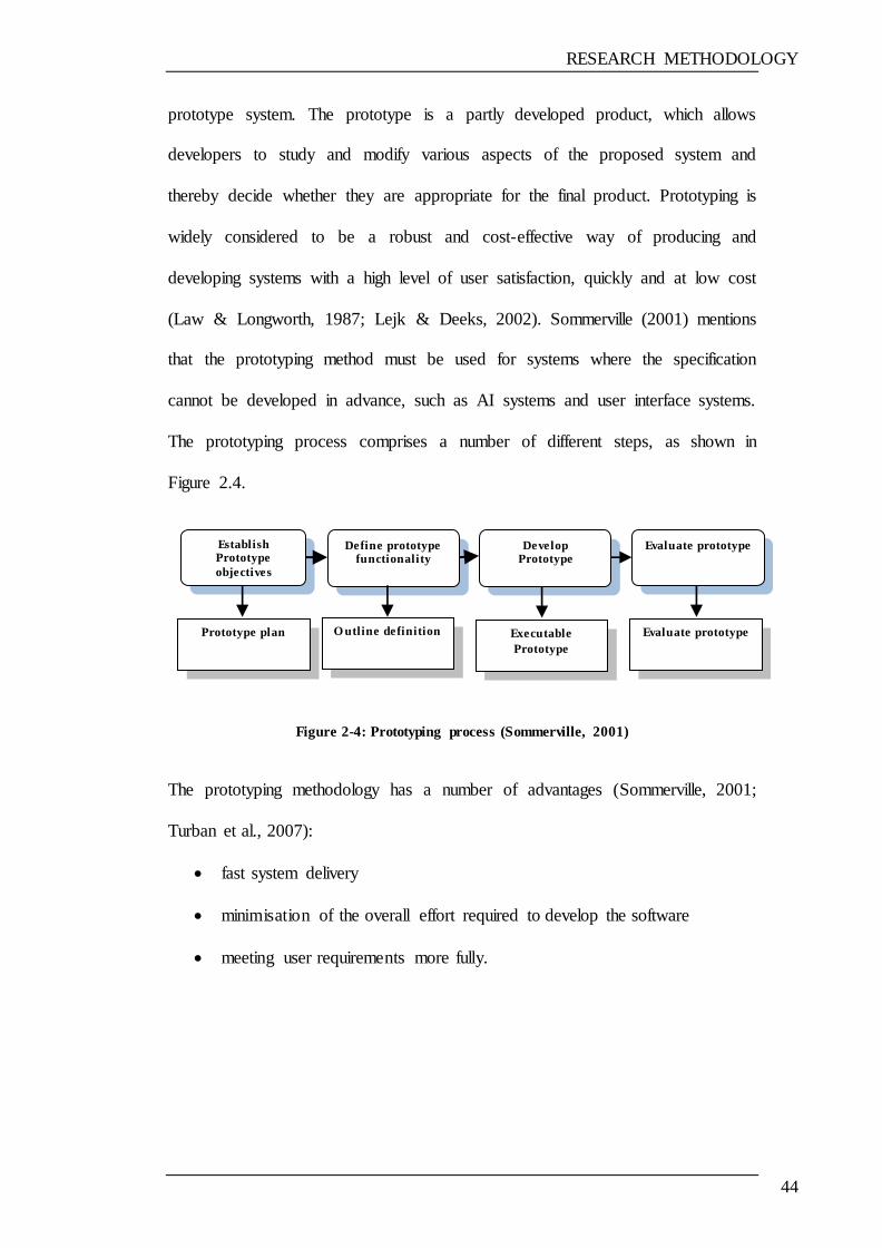
RESEARCH METHODOLOGY
44
prototype system. The prototype is a partly developed product, which allows
developers to study and modify various aspects of the proposed system and
thereby decide whether they are appropriate for the final product. Prototyping is
widely considered to be a robust and cost-effective way of producing and
developing systems with a high level of user satisfaction, quickly and at low cost
(Law & Longworth, 1987; Lejk & Deeks, 2002). Sommerville (2001) mentions
that the prototyping method must be used for systems where the specification
cannot be developed in advance, such as AI systems and user interface systems.
The prototyping process comprises a number of different steps, as shown in
Figure 2.4.
Figure 2-4: Prototyping process (Sommerville, 2001)
The prototyping methodology has a number of advantages (Sommerville, 2001;
Turban et al., 2007):
fast system delivery
minimisation of the overall effort required to develop the software
meeting user requirements more fully.
Establish Prototype
objectives
Define prototype functionality
Develop Prototype
Evaluate prototype
Evaluate prototype Executable
Prototype
O utline definition Prototype plan
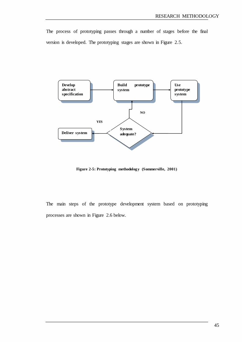
RESEARCH METHODOLOGY
45
The process of prototyping passes through a number of stages before the final
version is developed. The prototyping stages are shown in Figure 2.5.
Figure 2-5: Prototyping methodology (Sommerville, 2001)
The main steps of the prototype development system based on prototyping
processes are shown in Figure 2.6 below.
Develop
abstract
specification
Build prototype
system
Use
prototype
system
System
adequate? Deliver system
YES
NO
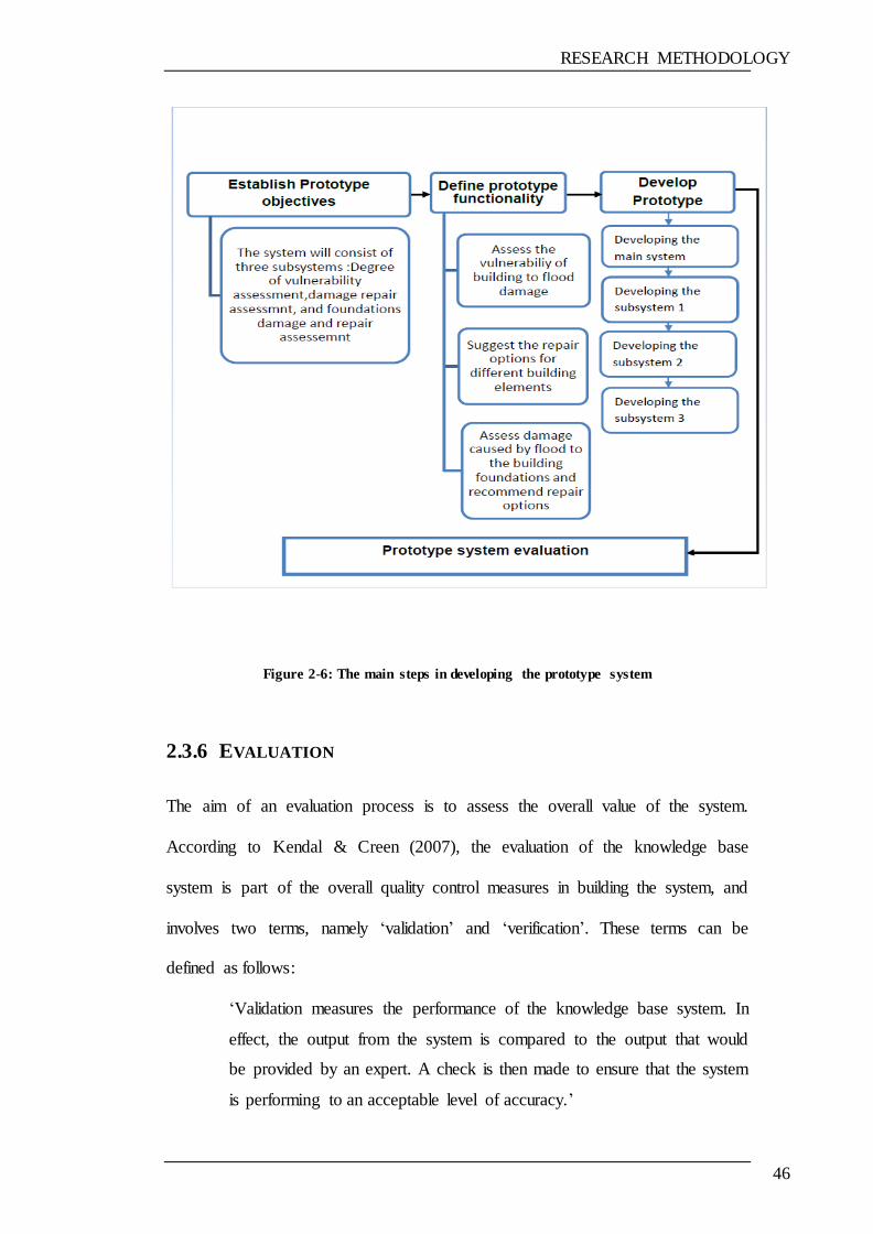
RESEARCH METHODOLOGY
46
Figure 2-6: The main steps in developing the prototype system
2.3.6 EVALUATION
The aim of an evaluation process is to assess the overall value of the system.
According to Kendal & Creen (2007), the evaluation of the knowledge base
system is part of the overall quality control measures in building the system, and
involves two terms, namely ‗validation‘ and ‗verification‘. These terms can be
defined as follows:
‗Validation measures the performance of the knowledge base system. In
effect, the output from the system is compared to the output that would
be provided by an expert. A check is then made to ensure that the system
is performing to an acceptable level of accuracy.‘
RESEARCH METHODOLOGY
47
(Kendal & Creen, 2007)
‗Verification is checking that the system has been built correctly, i.e., that
the rules are logical and consistent with the knowledge obtained via the
knowledge acquisition process.‘
(Kendal & Creen, 2007)
The prototype system was evaluated in two stages: during the development stage,
and following development. In the system evaluation which occurs during the
development stage, also known as ‗formative evaluation‘, the system was
demonstrated to a number of experts in order to validate and verify it. The
prototype subsequently went through several iterations with appropriate
refinements for its improvement. In the second stage of the evaluation, which
followed the development process, and which is also known as ‗summative
evaluation‘, several experts from different organisations were invited to give their
views and comments on the final prototype. The comments and recommendations
were noted, and various modifications were accordingly made to improve the
prototype system. The prototype evaluation pricesses and purpose is described in
detail in Chapter 7.
2.4 SUMMARY
In this chapter, the basic concepts and principles relating to the research
methodology were reviewed, and various types of research methodologies were
described. The chapter also described the methodology adopted in order to realise
the aim and the objectives of the research. The research methodology adopted
several approaches and such as literature review ,surveys, case study,

RESEARCH METHODOLOGY
48
questionnaires, prototype system developing and evaluation The next chapter
describes the model that developed in order to assess the vulnerability of
residential buildings to flood damage.

VULNERABILITY ASSESSMENT
49
CHAPTER 3 VULNERABILITY ASSESSMENT
3.1 INTRODUCTION
This chapter is divided into four main sections: a definition of vulnerability, an
explanation of vulnerability and hazard assessment with the provision of various
examples, the method developed to calculate the vulnerability of residential
buildings to flood damage, and a summary. This chapter reviews the vulnerability
assessment methods used mainly in relation to natural disasters, then discusses the
factors considered in the proposed model to calculate the vulnerability of
buildings to flood damage. Finally illustrate the developed model to calculate the
degree of vulnerability of building to flood damage.
3.2 DEFINITION OF VULNERABILITY
Vulnerability has been defined in various different ways by numerous experts on
the basis of what is the desired outcome. A number of different concepts have
been termed ‗vulnerability‘, as given below:
a measure, for a given population or region, of the underlying
factors that influence exposure to hazardous events and
predisposition to adverse consequences (Downing, 1993)
a characteristic of individuals and groups of people who inhabit a
given natural, social and economic space, within which they are
differentiated according to their varying position in society into
more or less vulnerable individuals and groups (Cannon, 1993)
the potential for attributes of a system to respond adversely to the
occurrence of hazardous events (Yamada et al., 1995)
VULNERABILITY ASSESSMENT
50
the extent to which a given hazard would impact on a property by
reason of its materials or layout (Clark et al., 1998)
the extent to which a natural or social system is susceptible to
sustaining damage from climate change (IPCC, 2001)
a function of a system‘s ability to cope with stress and shock
(Nicholls & Klein, 2000)
the propensity of social and ecological systems to suffer harm from
external stresses and shocks (International Council for Science,
2002)
a human condition or process resulting from physical, social,
economic and environmental factors, which ultimately determine
the likelihood and scale of damage from the impact of a given
hazard (UNDP, 2004).
Vulnerability is path dependent: the vulnerability of someone or
something at any point of time depends upon what has previously
happened to that person or thing (Green, 2004).
The word ‗vulnerability‘ comes from the Latin verb vulnerare,
meaning ‗to wound‘, and signifies exposure to physical or moral
harm (Alexander, 2005).
―the predisposition of an element or a system to be affected or
susceptible to damage‖ (Villagran de Leon, 2006)
The characteristics and circumstances of a community, system or
asset those make it susceptible to the damaging effects of a hazard‖
(UNISDR, 2009).
VULNERABILITY ASSESSMENT
51
For the purpose of this research, the term ‗vulnerability‘ is defined as the expected
susceptibility of a building to flood and the susceptibility of any building element
to damage from a flood event.
3.3 VULNERABILITY ASSESSMENT
A risk and vulnerability assessment helps to identify people and property, as well
as resources, that are considered to be at risk of injury or damage or loss resulting
from hazardous incidents or natural hazards. Amongst the tangible vulnerable
elements subjected to flood risk are buildings. A vulnerability assessment is the
process of estimating disaster potential in terms of what is susceptible to damage
(NCDEM, 1998; Kron, 2005). A building vulnerability assessment is important in
the evaluation of risk from flood hazards (Chen, Yin, and Dia, 2011).
The vulnerability assessment includes an inventory and assessment of potential
losses. There are two basic approaches which can be utilised in an attempt to
establish the degrees of vulnerability. The first approach is based on damage data
obtained from experiments or from field observations following the flood event.
The second approach is based on numerical models or simplified methods, or, if
no other method is available, on engineering judgments.
In the case of earthquake vulnerability assessment of buildings, which is similar to
flood vulnerability assessment, Tyagunov et al. (2004) state that there are two
principal approaches, namely observed vulnerability and predicted vulnerability.
Observed vulnerability refers to assessment based on the statistics of past
earthquake damage; predicted vulnerability refers to the assessment of
VULNERABILITY ASSESSMENT
52
performance expected of the buildings on the basis of engineering calculations
and design specifications, or, if there are no other means, t based on engineering
judgment. The second method is more appropriate when there are no data
available regarding the observed vulnerability.
3.3.1 EXAMPLES OF VULNERABILITY AND HAZARD ASSESSMENT
METHODS
One of the definitions which can be applied in the case of flood damage is that
suggested by Cardona (2003): ―Vulnerability: the degree of loss to a given
element at risk or set of such elements resulting from the occurrence of a natural
phenomenon of a given magnitude and expressed on a scale from 0 (no damage)
to 1 (total loss). On the other hand, vulnerability may be understood, in general
terms, as an internal risk factor, mathematically expressed in terms of the
feasibility that the exposed subject or system will be affected by the phenomenon
that characterizes the hazard.‖ In layman‘s terms, it means the degree to which an
individual, family, community, class or region is at risk from suffering a sudden
and serious misfortune following an extreme natural event (Buckle et al., 2000;
Fuchs, Heiss, and Hubl, 2007).
Examples of vulnerability and hazard assessment methods are provided below
with consideration to several aspects of geohazard vulnerability and risk
assessment:
Fiener & Haji (1999) developed a method to calculate the landslide hazard of
highway slopes, which was then used in highway slope management and
maintenance. The major causative factors which are known to influence slope
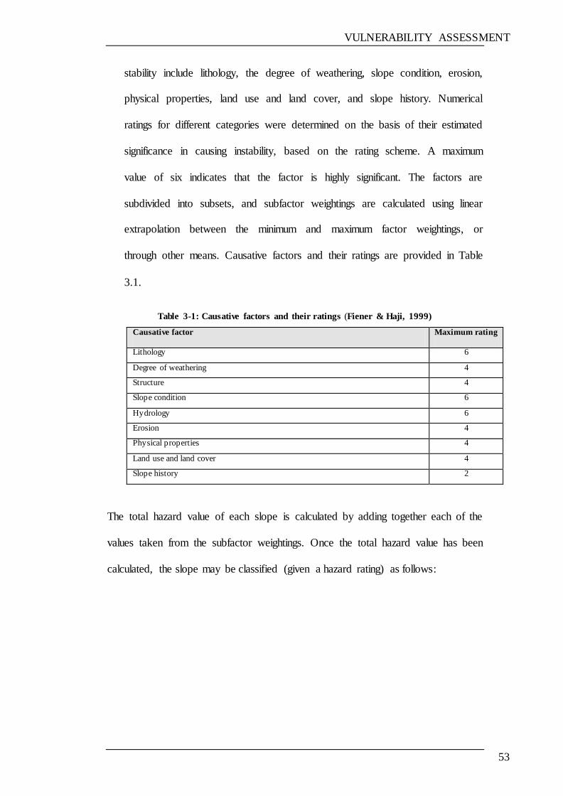
VULNERABILITY ASSESSMENT
53
stability include lithology, the degree of weathering, slope condition, erosion,
physical properties, land use and land cover, and slope history. Numerical
ratings for different categories were determined on the basis of their estimated
significance in causing instability, based on the rating scheme. A maximum
value of six indicates that the factor is highly significant. The factors are
subdivided into subsets, and subfactor weightings are calculated using linear
extrapolation between the minimum and maximum factor weightings, or
through other means. Causative factors and their ratings are provided in Table
3.1.
Table 3-1: Causative factors and their ratings (Fiener & Haji, 1999)
Causative factor Maximum rating
Lithology 6
Degree of weathering 4
Structure 4
Slope condition 6
Hydrology 6
Erosion 4
Physical properties 4
Land use and land cover 4
Slope history 2
The total hazard value of each slope is calculated by adding together each of the
values taken from the subfactor weightings. Once the total hazard value has been
calculated, the slope may be classified (given a hazard rating) as follows:

VULNERABILITY ASSESSMENT
54
HAZARD RATING TOTAL HAZARD VALUE
Very high hazard >32
High hazard 26-32
Moderate hazard 20-26
Low hazard 14-20
Very low hazard <14
Nicholas et al. (2001) developed a conceptual model for assessing flood
damage to UK domestic properties. The model originates from a critique of
the knowledge available at that time in the field, as well as from discussions
held with practitioners responsible for surveying, and recommended strategies
for the repair of such properties. The model comprises two independent
factors: building characteristics and flood characteristics. The dependent
variable is flood damage. The model is expressed as:
Flood damage = f (the flood characteristics + the building‘s characteristics) (1)
The flood characteristics are defined as:
the velocity of floodwater (m/s) in contact with a particular dwelling;
the contaminant content of the floodwater (grams/m3);
the time duration of the flood (hours/minutes).
The building‘s characteristics are defined as:
the frequency of flooding of the dwelling (number of times in period x);
the materials from which the building is constructed;
drying characteristics of the materials;
the condition of the building prior to being flooded.
VULNERABILITY ASSESSMENT
55
The mathematical relationships of the variables in equation (1) are then
identified as given below:
Fcx = flood characteristics that have been in contact with property x;
Dcx = dwelling characteristics of property x;
then:
Flood damage repair index = f (Fcx+Dcx)
and:
Fcx = f (Fxt ime + Fxcont + Fxdepth + Fxvel)
where:
Fxtime = the time duration of flood x;
Fxcont = the contaminant content of flood x;
Fxdepth = the depth of flood x;
Fxvel = the velocity flow of flood x.
Also:
Dxc = f (Dxloc+Dxfurnish+Dxconst)
where:
Dx loc = physical location of dwelling x;
Dx furnish = nature of furnishings of dwelling x;
Dxconst = construction characteristics of dwelling x.
Nicholas et al. (2001) stated that future research will determine the
quantitative values for all variables.
Papathoma & Dominey-Howes (2003) applied a tsunami vulnerability
assessment method to two coastal villages in the Gulf of Corinth, Greece,
using the tsunami of 7 February 1963 as a worst-case scenario. The
VULNERABILITY ASSESSMENT
56
vulnerability of each building (BV) in the inundation zone is then calculated
as follows:
BV = (7xa)+(6xb)+(5xc)+(4xd)+(3xe)+(2xf)+(1xg)
where:
(a) = the standardised score that is related to the materials of the
building;
(b) = the standardised score that is related to the row of the building;
(c) = the standardised score that is related to the number of floors the building has;
(d) = the standardised score that is related to the building‘s surroundings;
(e) = the standardised score that is related to the condition of the ground floor of
the building;
(f) = the standardised score that is related to the presence of sea defences in front
of the building;
(g) = the standardised score that is related to the width of the intertidal zone in
front of the building.
Owing to the fact that the vulnerability factors do not all have the same effect,
they then need to be ranked according to their importance. A weighting factor is
then applied, as shown in Table 3.2.

VULNERABILITY ASSESSMENT
57
Table 3-2: The criteria, their ratings and weighting factors (Nicholas et al. (2001)
Criterion Weighting factor
Building material 7
Row 6
Surroundings 5
Condition of ground floor 4
Number of floors 3
Sea defence 2
Natural environment 1
Sur (2005) adopted the weighting and rating values given in Table 3.3 below in an
attempt to assess the vulnerability of buildings subjected to earthquake damage in
Dhradan City (India).
The vulnerability assessment of a building is calculated using equation 3.1:
Final weighting = [10* (building shape sub-class rank)] + [8*(building age sub-
class rank)] + [6* (no. of storeys sub-class rank)] + [4* (building proximity sub-
class rank)] + [2* (building maintenance sub-class rank)].
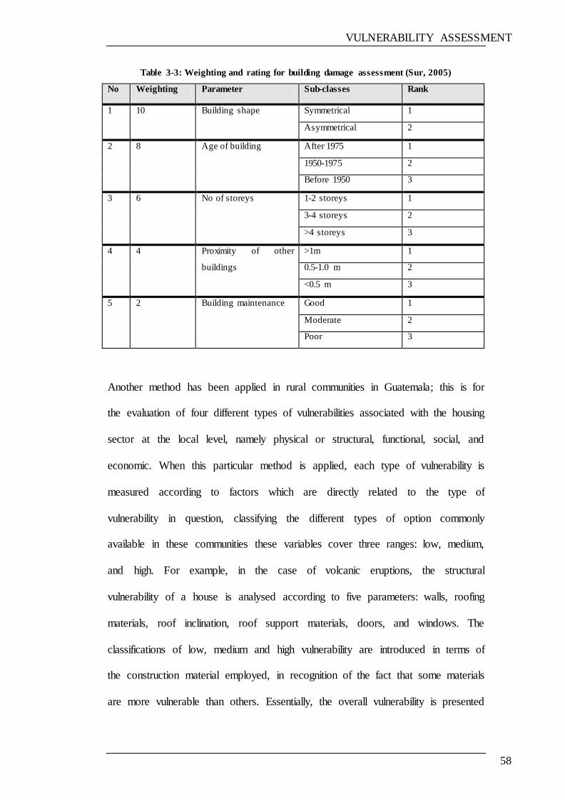
VULNERABILITY ASSESSMENT
58
Table 3-3: Weighting and rating for building damage assessment (Sur, 2005)
No Weighting Parameter Sub-classes Rank
1 10 Building shape Symmetrical 1
Asymmetrical 2
2 8 Age of building After 1975 1
1950-1975 2
Before 1950 3
3 6 No of storeys 1-2 storeys 1
3-4 storeys 2
>4 storeys 3
4 4 Proximity of other
buildings
>1m 1
0.5-1.0 m 2
<0.5 m 3
5 2 Building maintenance Good 1
Moderate 2
Poor 3
Another method has been applied in rural communities in Guatemala; this is for
the evaluation of four different types of vulnerabilities associated with the housing
sector at the local level, namely physical or structural, functional, social, and
economic. When this particular method is applied, each type of vulnerability is
measured according to factors which are directly related to the type of
vulnerability in question, classifying the different types of option commonly
available in these communities these variables cover three ranges: low, medium,
and high. For example, in the case of volcanic eruptions, the structural
vulnerability of a house is analysed according to five parameters: walls, roofing
materials, roof inclination, roof support materials, doors, and windows. The
classifications of low, medium and high vulnerability are introduced in terms of
the construction material employed, in recognition of the fact that some materials
are more vulnerable than others. Essentially, the overall vulnerability is presented
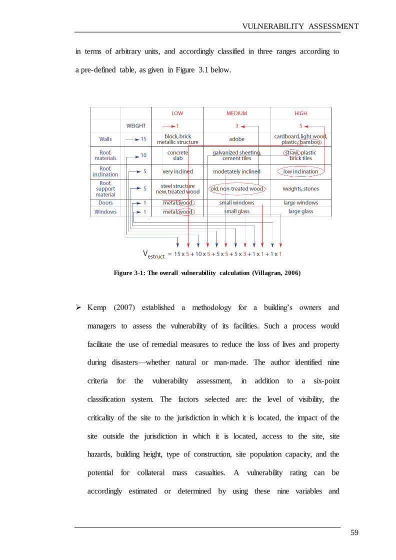
VULNERABILITY ASSESSMENT
59
in terms of arbitrary units, and accordingly classified in three ranges according to
a pre-defined table, as given in Figure 3.1 below.
Figure 3-1: The overall vulnerability calculation (Villagran, 2006)
Kemp (2007) established a methodology for a building‘s owners and
managers to assess the vulnerability of its facilities. Such a process would
facilitate the use of remedial measures to reduce the loss of lives and property
during disasters—whether natural or man-made. The author identified nine
criteria for the vulnerability assessment, in addition to a six-point
classification system. The factors selected are: the level of visibility, the
criticality of the site to the jurisdiction in which it is located, the impact of the
site outside the jurisdiction in which it is located, access to the site, site
hazards, building height, type of construction, site population capacity, and the
potential for collateral mass casualties. A vulnerability rating can be
accordingly estimated or determined by using these nine variables and
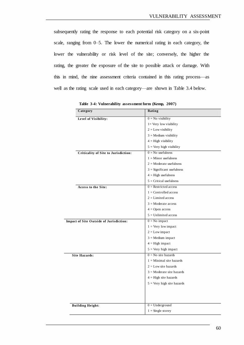
VULNERABILITY ASSESSMENT
60
subsequently rating the response to each potential risk category on a six-point
scale, ranging from 0–5. The lower the numerical rating in each category, the
lower the vulnerability or risk level of the site; conversely, the higher the
rating, the greater the exposure of the site to possible attack or damage. With
this in mind, the nine assessment criteria contained in this rating process—as
well as the rating scale used in each category—are shown in Table 3.4 below.
Table 3-4: Vulnerability assessment form (Kemp, 2007)
Category Rating
Level of Visibility: 0 = No visibility
1= Very low visibility
2 = Low visibility
3 = Medium visibility
4 = High visibility
5 = Very high visibility
Criticality of Site to Jurisdiction: 0 = No usefulness
1 = Minor usefulness
2 = Moderate usefulness
3 = Significant usefulness
4 = High usefulness
5 = Critical usefulness
Access to the Site:
0 = Restricted access
1 = Controlled access
2 = Limited access
3 = Moderate access
4 = Open access
5 = Unlimited access
Impact of Site O utside of Jurisdiction:
0 = No impact
1 = Very low impact
2 = Low impact
3 = Medium impact
4 = High impact
5 = Very high impact
Site Hazards: 0 = No site hazards
1 = Minimal site hazards
2 = Low site hazards
3 = Moderate site hazards
4 = High site hazards
5 = Very high site hazards
Building Height:
0 = Underground
1 = Single storey
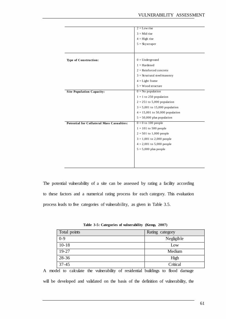
VULNERABILITY ASSESSMENT
61
2 = Low rise
3 = Mid rise
4 = High rise
5 = Skyscraper
Type of Construction:
0 = Underground
1 = Hardened
2 = Reinforced concrete
3 = Structural steel/masonry
4 = Light frame
5 = Wood structure
Site Population Capacity: 0 = No population
1 = 1 to 250 population
2 = 251 to 5,000 population
3 = 5,001 to 15,000 population
4 = 15,001 to 50,000 population
5 = 50,000 plus population
Potential for Collateral Mass Casualties: 0 = 0 to 100 people
1 = 101 to 500 people
2 = 501 to 1,000 people
3 = 1,001 to 2,000 people
4 = 2,001 to 5,000 people
5 = 5,000 plus people
The potential vulnerability of a site can be assessed by rating a facility according
to these factors and a numerical rating process for each category. This evaluation
process leads to five categories of vulnerability, as given in Table 3.5.
Table 3-5: Categories of vulnerability (Kemp, 2007)
Total points Rating category
0-9 Negligible
10-18 Low
19-27 Medium
28-36 High
37-45 Critical
A model to calculate the vulnerability of residential buildings to flood damage
will be developed and validated on the basis of the definition of vulnerability, the
VULNERABILITY ASSESSMENT
62
ideas and examples of vulnerability assessment using the similar ideas mentioned
in the previous examples. The will be discussed in next sections.
3.4 THE PROPOSED METHOD DEVELOPED TO
CALCULATE THE VULNERABILITY OF RESIDENTIAL
BUILDINGS TO FLOOD DAMAGE
The vulnerability of the elements at risk highlights how damaged buildings, or
any other elements, may react if they experience some degree of hazard, such as
floods. The loss measurement applied depends on the element at risk; therefore,
the loss can be measured as a proportion of the number of dead or injured to the
total population, as the cost of repair, or as the extent of physical damage
measured by an appropriate scale (Gwilliam et al., 2006). Assessing the
vulnerability of buildings in flood-prone areas is a key issue when evaluating the
risk induced by flood events; nevertheless, a comprehensive methodology for risk
assessment of buildings subject to flooding is still missing.
The model which has been developed is based on key factors—in particular, the
susceptibility of the building elements to damage by floodwater, as well as the
susceptibility of the entire building to flooding (e.g. as a result of its geographical
location). The damage that would occur to different elements of the building is
considered, as well as the building elements that would need to be repaired as a
result of flood damage, leaving aside other considerations (e.g. health risks). This
means that only physical damage to the building elements is considered.
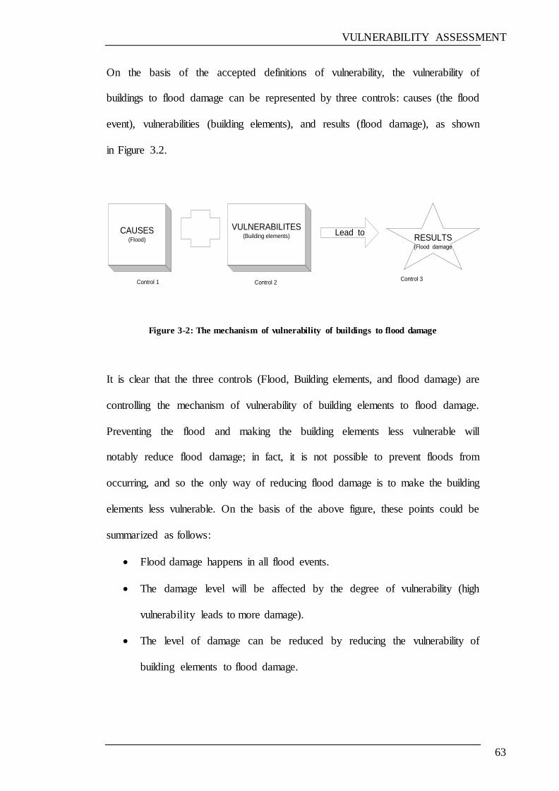
VULNERABILITY ASSESSMENT
63
On the basis of the accepted definitions of vulnerability, the vulnerability of
buildings to flood damage can be represented by three controls: causes (the flood
event), vulnerabilities (building elements), and results (flood damage), as shown
in Figure 3.2.
CAUSES(Flood)
VULNERABILITES(Building elements) Lead to
RESULTS(Flood damage
Control 1 Control 2Control 3
Figure 3-2: The mechanism of vulnerability of buildings to flood damage
It is clear that the three controls (Flood, Building elements, and flood damage) are
controlling the mechanism of vulnerability of building elements to flood damage.
Preventing the flood and making the building elements less vulnerable will
notably reduce flood damage; in fact, it is not possible to prevent floods from
occurring, and so the only way of reducing flood damage is to make the building
elements less vulnerable. On the basis of the above figure, these points could be
summarized as follows:
Flood damage happens in all flood events.
The damage level will be affected by the degree of vulnerability (high
vulnerability leads to more damage).
The level of damage can be reduced by reducing the vulnerability of
building elements to flood damage.
VULNERABILITY ASSESSMENT
64
The vulnerability of buildings to flood damage can be determined
according to how vulnerable they are and the other factors that put them at
risk of flooding.
Vulnerability tends to be greater when the risk of flooding is high.
The proposed model considers the flood damage caused to different
building elements.
3.4.1 THE STEPS IN THE DEVELOPMENT OF THE DEGREE OF
VULNERABILITY ASSESSMENT MODEL
Itemised information relating to flood damage to building structures is not always
available, and, owing to the lack of precise information or field measurements that
can be used to develop the vulnerability assessment model, it has been necessary
to rely on references, technical reports and research papers, as well as the
questionnaire.
The model for calculating the vulnerability of buildings to flood damage has been
developed on the basis of the vulnerability definitions provided at the beginning
of this chapter, as well as the examples of methods detailed for the calculation of
vulnerability, given in Section 3.3.1, and the discussion in Section 3.3.2.
The developed model is based on the ordinal scale relative weighting-rating
technique. With this in mind, the flow chart shown in Figure 3.3 below shows the
key stages involved in the vulnerability assessment adopted in this research. The
description of the different steps is presented in the following sections.

VULNERABILITY ASSESSMENT
65
Figure 3-3: Major steps of vulnerability assessment used in this research
3.4.1.1 Identification of factors contributing to vulnerability
Brooks (2003) compares two viewpoints from which vulnerability could be
viewed in the climate change literature:
Identifying the factors contributing to vulnerability
using descriptive research methodology `
Developing a questionnaire to investigate the factors
contributing to vulnerability
Weighting of factors based on their importance
Developing a computer program to calculate the
vulnerability
Defining the vulnerability of the building to flood
damage
Developing the vulnerability calculation equation
VULNERABILITY ASSESSMENT
66
i. The amount of damage caused to a system by a particular hazard (physical
vulnerability)
ii. a state that exists within a system before it encounters a hazard (social
vulnerability).
The first concept was considered when developing the vulnerability assessment
model. The vulnerability assessed by the model and the factors considered (as
given in table 6.3) aimed to calculate the physical vulnerability (damage) caused
by flood to different building elements.
It can be stated that vulnerability is determined by various factors (Kunreuther et
al., 2004). For the purpose of assessing the vulnerability of a building to flood
damage, a number of factors have been identified, based on various sources,
including the literature, previous cases, and discussions with experts in the field.
The following list of general issues can help to assess whether or not a particular
property is subject to flood damage (OPDM, 2003):
Has the property or surrounding land and gardens ever been flooded in the
past?
Has the property been issued with a flood warning?
Is the property close to a surface water drainage ditch or stream that could
overflow?
Is the property in a hollow or a low-lying area or at the bottom of a hill?
Is the property protected by river or coastal defences?
VULNERABILITY ASSESSMENT
67
Is the area at risk from groundwater flooding?
If the answer to all of these questions is negative, the vulnerability of the property
to flood damage is considered small; on the other hand, if the answer to one or
more of these questions is ‗yes‘, this suggests that the vulnerability of this
property to flood damage is high.
A variety of approaches use indicators for vulnerability assessment in the field of
risk analysis (Cardona, 2006; Cutter et al., 2003; Dilley et al., 2005; Peduzzi,
2006). These approaches focus on assessing risk and vulnerability quantitatively
by means of indicators (Birkmann, 2007; Schmidtlein, 2008).
The indicators in the vulnerability assessment can be used to evaluate adaptive
strategies and measures. On this basis, factors (or indicators) have been selected
which seem to be important and which make the building more vulnerable to
flood damage. The selection of factors is based on:
their contribution to vulnerability to flood damage
susceptibility of materials to flood damage
increased cost of repair
the building being more at risk of damage when subjected to flooding (e.g.
fair condition of the building)
things that make the building more vulnerable to flood damage than would
otherwise be the case.
The factors that are believed to contribute to the vulnerability of a building to
flood damage were selected on the basis of reports in the available literature that
these factors contribute in some way to building flood damage. The factors
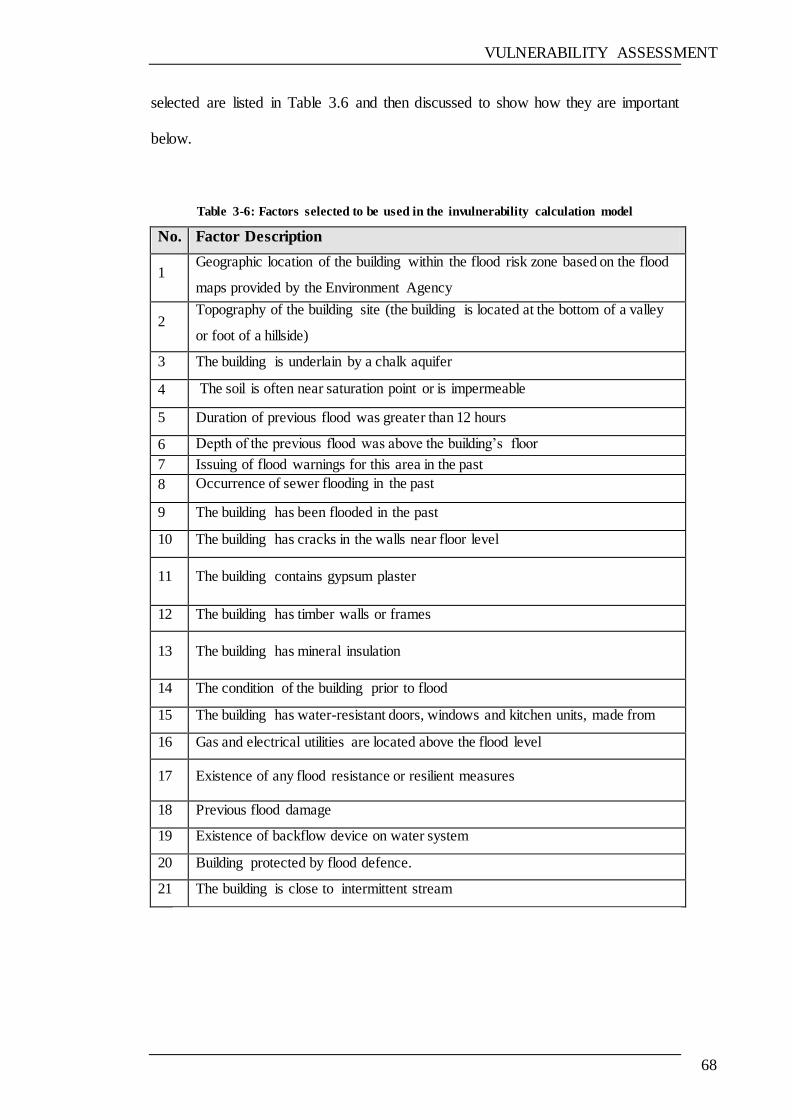
VULNERABILITY ASSESSMENT
68
selected are listed in Table 3.6 and then discussed to show how they are important
below.
Table 3-6: Factors selected to be used in the invulnerability calculation model
No. Factor Description
1 Geographic location of the building within the flood risk zone based on the flood
maps provided by the Environment Agency
2 Topography of the building site (the building is located at the bottom of a valley
or foot of a hillside)
3 The building is underlain by a chalk aquifer
4 The soil is often near saturation point or is impermeable
5 Duration of previous flood was greater than 12 hours
6 Depth of the previous flood was above the building‘s floor
7 Issuing of flood warnings for this area in the past
8 Occurrence of sewer flooding in the past
9 The building has been flooded in the past
10 The building has cracks in the walls near floor level
11 The building contains gypsum plaster
12 The building has timber walls or frames
13 The building has mineral insulation
14 The condition of the building prior to flood
15 The building has water-resistant doors, windows and kitchen units, made from
PVC or other water resistant materials 16 Gas and electrical utilities are located above the flood level
17 Existence of any flood resistance or resilient measures
18 Previous flood damage
19 Existence of backflow device on water system
20 Building protected by flood defence.
21 The building is close to intermittent stream
VULNERABILITY ASSESSMENT
69
1. Geographic location of the building within the flood risk zone, based on
flood maps provided by the Environment Agency (EA)
Geographic location is an important factor that needs to be considered in cases of
flood damage (Rhodes, and Proverbs, 2008). A flood map is intended to act as a
guide only. It can be used to find the predicted risk of flooding from rivers and the
sea in a certain area. A building could be at risk from other sources of flooding.
The following two easy steps are offered on the Environment Agency site:
a) Search for your post code, using the search box on the right of the
map page (http://www.environment-agency.gov.uk/homeandleisure/
floods/default.aspx) to establish your location on the map.
b) Once you can see your location on the map, click on the point you
are interested in. You will then see a guide to the chance of flooding
in your area, i.e. low, moderate or significant.
There are two different kinds of area shown on the flood map. They can be
described as follows:
‗Dark blue shows the area that could be affected by flooding, either from rivers
or the sea, if there were no flood defences. This area could be flooded:
From the sea by a flood that has a 0.5% (1 in 200) or greater
chance of happening each year.
Or from a river by a flood that has a 1% (1 in 100) or greater
chance of happening each year.
VULNERABILITY ASSESSMENT
70
Light blue shows the additional extent of an extreme flood from rivers
or the sea. These outlying areas are likely to be affected by a major flood,
with up to a 0.1% (1 in 1000) chance of occurring each year.‘ (EA, 2008)
These two colours show the extent of the natural floodplain if there were no flood
defences or certain other manmade structures and channel improvements.
2. Topography of the building site
The topography of the building site is considered to be one of the most important
factors when determining the degree of vulnerability of the building to damage as
a result of flooding, since a building which is located in a valley or at the bottom
of a hill is at risk of flooding from water flowing from the top of the slope and
gathering quickly into a large amount, thereby making the building more
vulnerable to the risk of damage due to flooding.
3. The building is underlain by a chalk aquifer
Groundwater flooding occurs when water levels in the ground rise above surface
elevations. Chalk, which is a permeable rock, forms aquifers, because the chalk
stores groundwater and allows it to flow. The chalk areas show some of the largest
seasonal variations at groundwater level, and are the most extensive sources of
groundwater flooding. Figure 3.4 shows the extent of chalk on the UK geological
map.
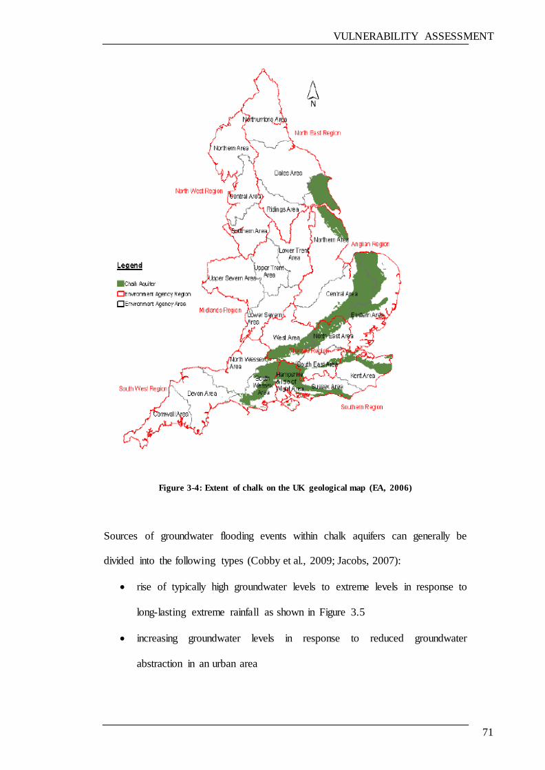
VULNERABILITY ASSESSMENT
71
Figure 3-4: Extent of chalk on the UK geological map (EA, 2006)
Sources of groundwater flooding events within chalk aquifers can generally be
divided into the following types (Cobby et al., 2009; Jacobs, 2007):
rise of typically high groundwater levels to extreme levels in response to
long-lasting extreme rainfall as shown in Figure 3.5
increasing groundwater levels in response to reduced groundwater
abstraction in an urban area

VULNERABILITY ASSESSMENT
72
rise of groundwater levels owing to leaking sewers, drains and water
supply mains
increases in groundwater levels and changed flow paths owing to artificial
obstructions, including deep foundations and quarries, and loss of natural
drainage paths
inundation of trenches intercepting high groundwater levels.
Recent and historical records show that groundwater as the source of flooding
where there are areas vulnerable to ground water flood (Cobby et al., 2009).
Figure 3-5: Groundwater rising during winter in chalk soil (Cobby et al., 2009)

VULNERABILITY ASSESSMENT
73
Groundwater flooding may take weeks or months to dissipate as it moves much
more slowly than surface water (Macdonald et al., 2008). Flooding from
groundwater is most likely to occur in areas of chalk, limestone or other aquifers.
Notably, heavy rainfall in the autumn of 2000 followed the wettest 12-month
period in many areas of England and Wales (AIR, 2008). These large amounts of
rain led to many of the aquifers being filled earlier than usual, leading to
unusually high levels of groundwater in some areas, so that surface water and
springs often formed in places where people had not been aware of the presence
of springs for a generation or more (Jacobs, 2007). As a result, almost one
thousand homes and businesses were affected by groundwater flooding (ODPM,
2003).
4. The soil is often near saturation point or is impermeable
The soil becomes saturated at the point at which the soil or aquifer will not absorb
any further amounts of water (Jacobs, 2007). Overland flows can be caused by
heavy rains falling on saturated ground, where groundwater levels are already
high, or on paved areas. Properties can be flooded by overland flows if they are
located in areas where floodwater can accumulate. Paved areas, such as roads, can
work as channels for overland flows. Properties can be flooded by overland flows
if they are located in areas that can accumulate water (ODPM, 2003).
5. Duration of previous flood was greater than 12 hours
Flood duration—which is the time during which floodwaters are in contact with
the building—is also a key factor in determining the level of damage. Generally,
the longer the period of flooding, the more damage would be caused to the
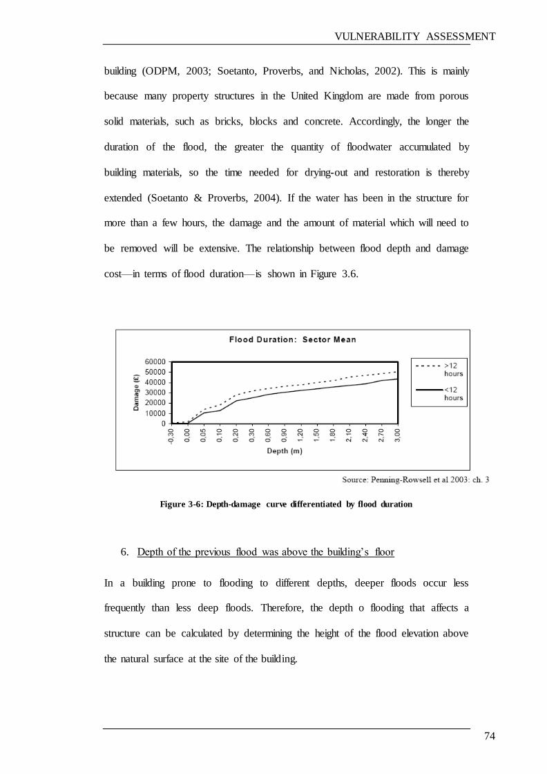
VULNERABILITY ASSESSMENT
74
building (ODPM, 2003; Soetanto, Proverbs, and Nicholas, 2002). This is mainly
because many property structures in the United Kingdom are made from porous
solid materials, such as bricks, blocks and concrete. Accordingly, the longer the
duration of the flood, the greater the quantity of floodwater accumulated by
building materials, so the time needed for drying-out and restoration is thereby
extended (Soetanto & Proverbs, 2004). If the water has been in the structure for
more than a few hours, the damage and the amount of material which will need to
be removed will be extensive. The relationship between flood depth and damage
cost—in terms of flood duration—is shown in Figure 3.6.
Figure 3-6: Depth-damage curve differentiated by flood duration
6. Depth of the previous flood was above the building‘s floor
In a building prone to flooding to different depths, deeper floods occur less
frequently than less deep floods. Therefore, the depth o flooding that affects a
structure can be calculated by determining the height of the flood elevation above
the natural surface at the site of the building.
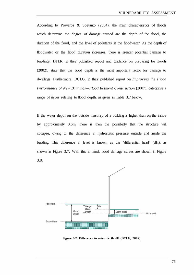
VULNERABILITY ASSESSMENT
75
According to Proverbs & Soetanto (2004), the main characteristics of floods
which determine the degree of damage caused are the depth of the flood, the
duration of the flood, and the level of pollutants in the floodwater. As the depth of
floodwater or the flood duration increases, there is greater potential damage to
buildings. DTLR, in their published report and guidance on preparing for floods
(2002), state that the flood depth is the most important factor for damage to
dwellings. Furthermore, DCLG, in their published report on Improving the Flood
Performance of New Buildings—Flood Resilient Construction (2007), categorise a
range of issues relating to flood depth, as given in Table 3.7 below.
If the water depth on the outside masonry of a building is higher than on the inside
by approximately 0.6m, there is then the possibility that the structure will
collapse, owing to the difference in hydrostatic pressure outside and inside the
building. This difference in level is known as the ‗differential head‘ (dH), as
shown in Figure 3.7. With this in mind, flood damage curves are shown in Figure
3.8.
Figure 3-7: Difference in water depth dH (DCLG, 2007)
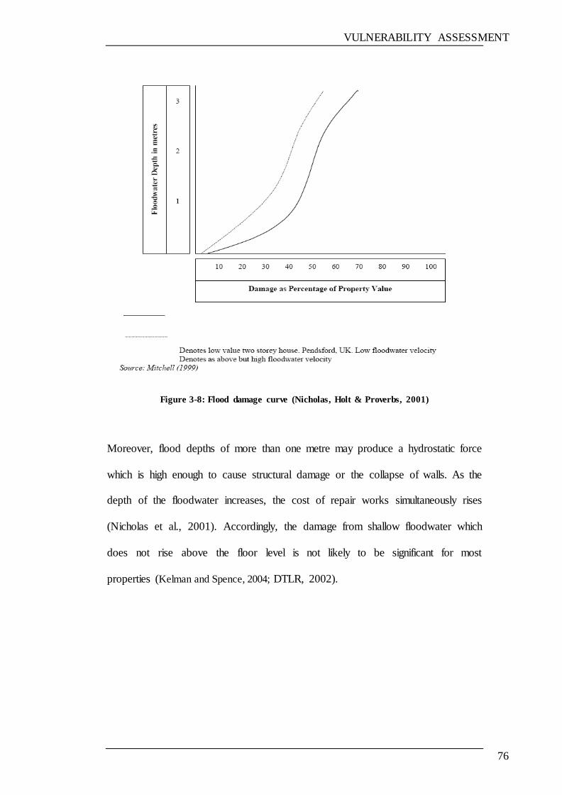
VULNERABILITY ASSESSMENT
76
Figure 3-8: Flood damage curve (Nicholas, Holt & Proverbs, 2001)
Moreover, flood depths of more than one metre may produce a hydrostatic force
which is high enough to cause structural damage or the collapse of walls. As the
depth of the floodwater increases, the cost of repair works simultaneously rises
(Nicholas et al., 2001). Accordingly, the damage from shallow floodwater which
does not rise above the floor level is not likely to be significant for most
properties (Kelman and Spence, 2004; DTLR, 2002).
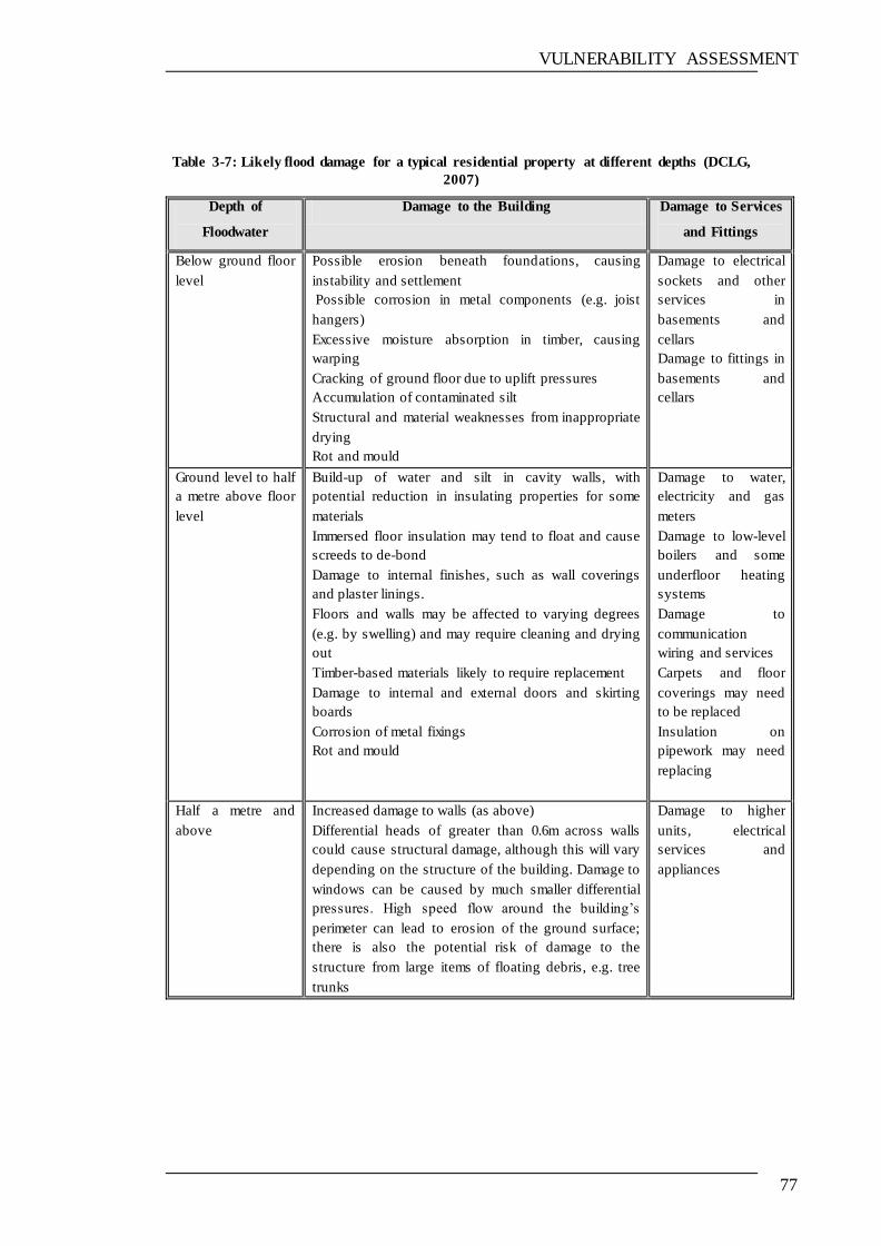
VULNERABILITY ASSESSMENT
77
Table 3-7: Likely flood damage for a typical residential property at different depths (DCLG,
2007)
Depth of
Floodwater
Damage to the Building Damage to Services
and Fittings
Below ground floor
level
Possible erosion beneath foundations, causing
instability and settlement
Possible corrosion in metal components (e.g. joist
hangers)
Excessive moisture absorption in timber, causing
warping
Cracking of ground floor due to uplift pressures
Accumulation of contaminated silt
Structural and material weaknesses from inappropriate
drying
Rot and mould
Damage to electrical
sockets and other
services in
basements and
cellars
Damage to fittings in
basements and
cellars
Ground level to half
a metre above floor
level
Build-up of water and silt in cavity walls, with
potential reduction in insulating properties for some
materials
Immersed floor insulation may tend to float and cause
screeds to de-bond
Damage to internal finishes, such as wall coverings
and plaster linings.
Floors and walls may be affected to varying degrees
(e.g. by swelling) and may require cleaning and drying
out
Timber-based materials likely to require replacement
Damage to internal and external doors and skirting
boards
Corrosion of metal fixings
Rot and mould
Damage to water,
electricity and gas
meters
Damage to low-level
boilers and some
underfloor heating
systems
Damage to
communication
wiring and services
Carpets and floor
coverings may need
to be replaced
Insulation on
pipework may need
replacing
Half a metre and
above
Increased damage to walls (as above)
Differential heads of greater than 0.6m across walls
could cause structural damage, although this will vary
depending on the structure of the building. Damage to
windows can be caused by much smaller differential
pressures. High speed flow around the building‘s
perimeter can lead to erosion of the ground surface;
there is also the potential risk of damage to the
structure from large items of floating debris, e.g. tree
trunks
Damage to higher
units, electrical
services and
appliances
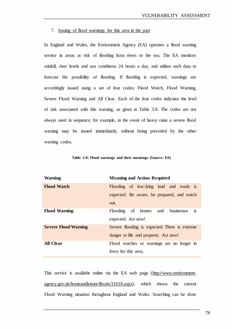
VULNERABILITY ASSESSMENT
78
7. Issuing of flood warnings for this area in the past
In England and Wales, the Environment Agency (EA) operates a flood warning
service in areas at risk of flooding from rivers or the sea. The EA monitors
rainfall, river levels and sea conditions 24 hours a day, and utilises such data to
forecast the possibility of flooding. If flooding is expected, warnings are
accordingly issued using a set of four codes: Flood Watch, Flood Warning,
Severe Flood Warning and All Clear. Each of the four codes indicates the level
of risk associated with this warning, as given in Table 3.8. The codes are not
always used in sequence; for example, in the event of heavy rains a severe flood
warning may be issued immediately, without being preceded by the other
warning codes.
Table 3-8: Flood warnings and their meanings (Source: EA)
Warning Meaning and Action Required
Flood Watch Flooding of low-lying land and roads is
expected. Be aware, be prepared, and watch
out.
Flood Warning Flooding of homes and businesses is
expected. Act now!
Severe Flood Warning Severe flooding is expected. There is extreme
danger to life and property. Act now!
All Clear Flood watches or warnings are no longer in
force for this area.
This service is available online via the EA web page (http://www.environment-
agency.gov.uk/homeandleisure/floods/31618.aspx), which shows the current
Flood Warning situation throughout England and Wales. Searching can be done
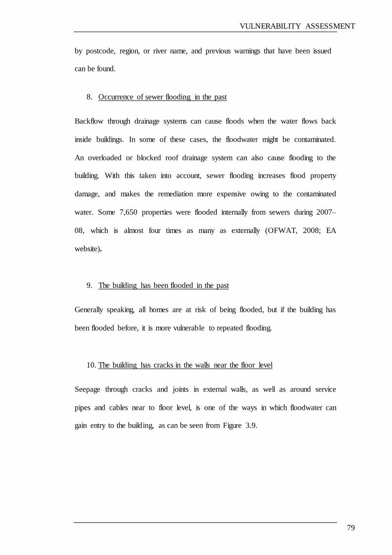
VULNERABILITY ASSESSMENT
79
by postcode, region, or river name, and previous warnings that have been issued
can be found.
8. Occurrence of sewer flooding in the past
Backflow through drainage systems can cause floods when the water flows back
inside buildings. In some of these cases, the floodwater might be contaminated.
An overloaded or blocked roof drainage system can also cause flooding to the
building. With this taken into account, sewer flooding increases flood property
damage, and makes the remediation more expensive owing to the contaminated
water. Some 7,650 properties were flooded internally from sewers during 2007–
08, which is almost four times as many as externally (OFWAT, 2008; EA
website).
9. The building has been flooded in the past
Generally speaking, all homes are at risk of being flooded, but if the building has
been flooded before, it is more vulnerable to repeated flooding.
10. The building has cracks in the walls near the floor level
Seepage through cracks and joints in external walls, as well as around service
pipes and cables near to floor level, is one of the ways in which floodwater can
gain entry to the building, as can be seen from Figure 3.9.
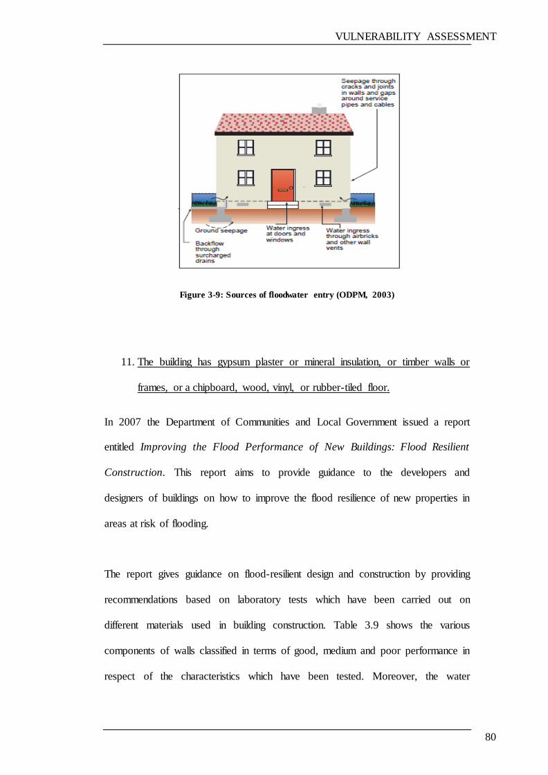
VULNERABILITY ASSESSMENT
80
Figure 3-9: Sources of floodwater entry (ODPM, 2003)
11. The building has gypsum plaster or mineral insulation, or timber walls or
frames, or a chipboard, wood, vinyl, or rubber-tiled floor.
In 2007 the Department of Communities and Local Government issued a report
entitled Improving the Flood Performance of New Buildings: Flood Resilient
Construction. This report aims to provide guidance to the developers and
designers of buildings on how to improve the flood resilience of new properties in
areas at risk of flooding.
The report gives guidance on flood-resilient design and construction by providing
recommendations based on laboratory tests which have been carried out on
different materials used in building construction. Table 3.9 shows the various
components of walls classified in terms of good, medium and poor performance in
respect of the characteristics which have been tested. Moreover, the water
VULNERABILITY ASSESSMENT
81
sensitivity of different materials used in building construction, based on
laboratory tests, is shown in Table 3.10.
It is clear from the tables below that gypsum plaster, mineral and blown-in
insulation, and timber are materials which can easily be affected by water and
damaged. These materials have been classified in terms of performance
characteristics as poor, and are therefore unsuitable for use as construction
materials owing to their largest water sensitivity.
Table 3-9: Flood resilience characteristics of walls (based on laboratory testing) (DEFRA
and EA, 2007)
Material
Resilience Characteristics* Overall
resilience performance
Water
penetration
Drying
ability
Retention of pre-flood
dimensions,
Integrity
External Face
Engineering
bricks (Classes
A and B)
Good Good Good Good
Facing bricks
(wire cut, sand
facing)
Medium Medium Good Medium
Internal Face
Concrete
Blocks Poor Medium Good Medium
Aircrete Medium Poor Good Medium
Cavity Insulation
Mineral fibre Poor Poor Poor Poor
Blown-in Poor Poor Poor Poor
Rigid PU foam Medium Medium Good Medium
Renders/Plaster
Cement render—external Good Good Good Good
Cement/lime
Render—external Good Good Good Good
Gypsum
plasterboard Poor
Not
assessed Poor Poor
Lime plaster
Poor
Not
assessed Poor Poor

VULNERABILITY ASSESSMENT
82
Table 3-10: Water sensitivity of materials (CIRIA, 2005a).
Material Example Water Sensitivity
Gypsum-based
materials
Plaster
Plasterboard
Plaster render/Wall plaster
-
-
-
Lime-based
materials
Mortar and render
Limestone
+
+
Cement-based
materials
Mortar and render
Concrete
Concrete blocks
Concrete floor
+
+
+
+
Fired-clay materials Brick
Clinker block
Glazed ceramic tiles
Unglazed earthenware
+
+
+
O
Timber Joists and beams
Floorboards and planks
Chipboard and particleboard
Cellulose insulation board
Parquet flooring
- to +
-
-
-
-
Metal Steel beams and joists
Copper/zinc sheet
+
+
Plastics Various - to +
Bitumen materials Gaskets
Bitumen paint
+
+
{‗+‘ good suitability (no or limited water sensitivity), ‗O‘ moderate suitability (some water sensitivity) ‗-‘ unsuitable
(strong water sensitivity)}
12. The condition of the building prior to the flood
The condition of the building before being flooded is also an important factor that
influences flood damage (Proverbs & Soetanto, 2004). A building which is not
well repaired and maintained will be more seriously affected by flooding.
VULNERABILITY ASSESSMENT
83
13. The building has water resistant doors, windows and kitchen units, made
from PVC or other water resistant materials.
―Doors, windows, skirting boards, architraves, doorframes and window frames
with Fibreglass (GRP), plastic, uPVC or other similar water resistant
alternatives … do not absorb water or warp and so are more readily functional
after a flood‖ (CIRIA, 2005a).
14. Gas and electric utilities are located above the flood level
Gas meters, electricity meters and consumer units (fuse boxes) can be affected by
floodwater. If they are located above the expected flood levels during
refurbishment works, this will subsequently reduce the cost of replacing them if
they come into contact with floodwater (CIRIA Advice sheet 7, 2003a).
15. Existence of any flood resistance or resilience measures
Resistance construction is the construction of a building in such a way as to
prevent floodwater entering it and damaging its materials and structure. Resilience
construction is the construction of a building in such a way that, although
floodwater may enter, its impact is reduced, in that no permanent damage is
caused, structural integrity is maintained, and drying and cleaning is made easy.
The existence of any resistance or resilience measures will reduce the time and
costs associated with repairing the property (Broadbent, 2004; Escarameia et al.,
2007; Department for Environment, Food and Rural Affairs, 2008). Flood
resistance or resilience measures include (Bowker, 2007):
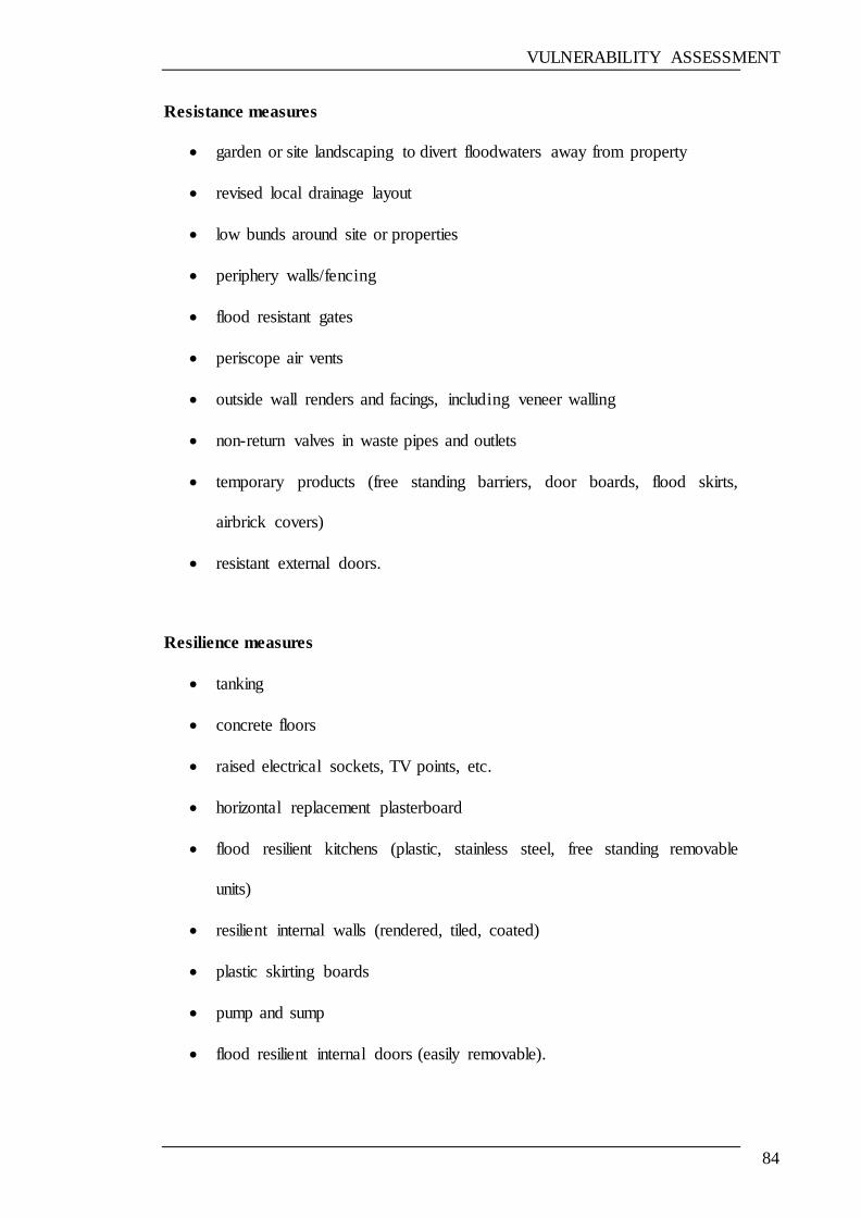
VULNERABILITY ASSESSMENT
84
Resistance measures
garden or site landscaping to divert floodwaters away from property
revised local drainage layout
low bunds around site or properties
periphery walls/fencing
flood resistant gates
periscope air vents
outside wall renders and facings, including veneer walling
non-return valves in waste pipes and outlets
temporary products (free standing barriers, door boards, flood skirts,
airbrick covers)
resistant external doors.
Resilience measures
tanking
concrete floors
raised electrical sockets, TV points, etc.
horizontal replacement plasterboard
flood resilient kitchens (plastic, stainless steel, free standing removable
units)
resilient internal walls (rendered, tiled, coated)
plastic skirting boards
pump and sump
flood resilient internal doors (easily removable).

VULNERABILITY ASSESSMENT
85
16. Building protected by flood defence
Building flood resistance can be increased by providing temporary building-level
flood defence measures, such as installing flood boards on doorways or covers on
service ducts (DCLG/Environment Agency, 2007).
3.4.1.2 The degree of vulnerability assessment model
It was part of the research plan to obtain detailed information concerning the
factors considered by previous cases, which can be used to conduct statistical
analysis in order to distinguish between these factors, as well as to exclude non-
important ones. It was expected that several points would be addressed relating to
this information, but this information was not available, with the exception of
some general statistical data. For this reason, the weighting and rating of factors
was done in a way that relies mainly on past experience and expert opinion in this
area. This method has been used in previous cases, as given in examples of
vulnerability assessment (Section 3.3.1). Notably, factors which are believed to
cause the damage of buildings as a result of flooding were also identified on the
basis of existing references, as well as a questionnaire which has been prepared
for the purpose of demonstrating the importance of these factors, as well as the
possibility of adding any other factors that the participants think it is important.
Based on the methods applied to assess the risk in the examples illustrated in
Section 3.3.1, a method was developed in a similar way, and involves the
following steps:
1. The factors which are believed to cause the collapse of buildings as a
result of flooding were identified on the basis of existing literature and
VULNERABILITY ASSESSMENT
86
expert opinions obtained during the workshops attended in relation to the
topic.
2. Since, there are no data available to carry out a statistical analysis which
allows the investigation of these factors. In this research, only the relative
importance of these factors in contributing to flood damage is considered.
Accordingly, it is important to distinguish between the degrees of
importance of such factors. For this purpose, a survey has been conducted
in order to investigate the value of such factors, and to give participants
the opportunity to add any other factors which they believe contribute to
building flood damage. A copy of this survey is shown in the appendices.
The main aim of this survey is to rank these factors in two groups—either
important or very important.
3. The next step is to incorporate weighting and rating, which are generally
used in risk assessment, where a weighting is assigned to each risk factor.
The reason for this is that the risk factors are not all equally important, and
weighting should be assigned to each risk factor in order to reflect its
perceived importance. For this purpose—and based on the survey
results—the factors are divided into two groups: important and very
important.
After the factors have been divided into the two different groups, their ratings are
then converted to numerical weightings. In the case of the risk assessment,
weightings can be derived for each factor by applying statistical techniques or
otherwise assigned through expert judgement. In this research, the weighting is
assigned by expert judgment since statistical analysis is not applicable.
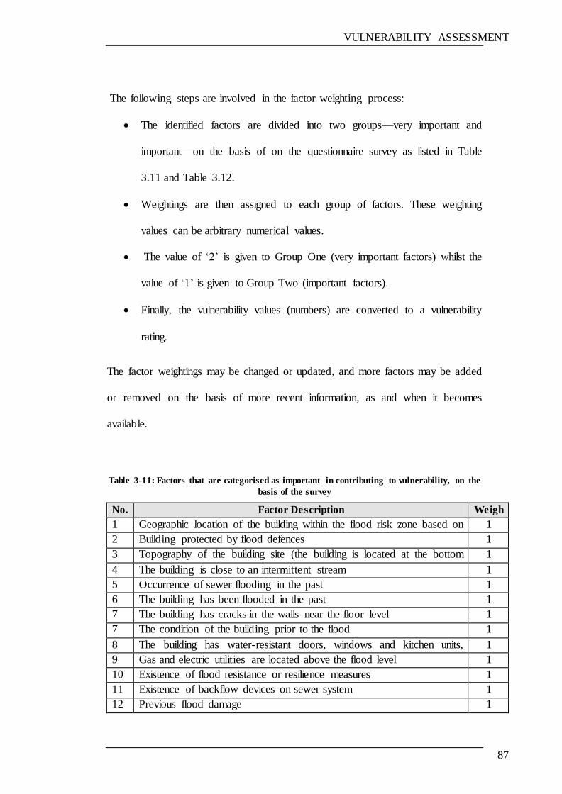
VULNERABILITY ASSESSMENT
87
The following steps are involved in the factor weighting process:
The identified factors are divided into two groups—very important and
important—on the basis of on the questionnaire survey as listed in Table
3.11 and Table 3.12.
Weightings are then assigned to each group of factors. These weighting
values can be arbitrary numerical values.
The value of ‗2‘ is given to Group One (very important factors) whilst the
value of ‗1‘ is given to Group Two (important factors).
Finally, the vulnerability values (numbers) are converted to a vulnerability
rating.
The factor weightings may be changed or updated, and more factors may be added
or removed on the basis of more recent information, as and when it becomes
available.
Table 3-11: Factors that are categorised as important in contributing to vulnerability, on the
basis of the survey
No. Factor Description Weigh
t 1 Geographic location of the building within the flood risk zone based on
the flood maps provided by the Environment Agency
1
2 Building protected by flood defences 1
3 Topography of the building site (the building is located at the bottom
of a valley or the foot of a hillside)
1
4 The building is close to an intermittent stream 1
5 Occurrence of sewer flooding in the past 1
6 The building has been flooded in the past 1
7 The building has cracks in the walls near the floor level 1
7 The condition of the building prior to the flood 1
8 The building has water-resistant doors, windows and kitchen units,
made from PVC or other water-resistant materials
1
9 Gas and electric utilities are located above the flood level 1
10 Existence of flood resistance or resilience measures 1
11 Existence of backflow devices on sewer system 1
12 Previous flood damage 1
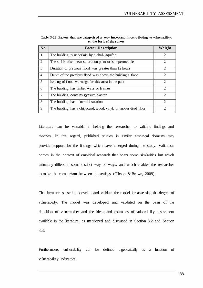
VULNERABILITY ASSESSMENT
88
Table 3-12: Factors that are categorised as very important in contributing to vulnerability,
on the basis of the survey
No. Factor Description Weight
1 The building is underlain by a chalk aquifer 2
2 The soil is often near saturation point or is impermeable 2
3 Duration of previous flood was greater than 12 hours 2
4 Depth of the previous flood was above the building‘s floor 2
5 Issuing of flood warnings for this area in the past 2
6 The building has timber walls or frames 2
7 The building contains gypsum plaster 2
8 The building has mineral insulation 2
9 The building has a chipboard, wood, vinyl, or rubber-tiled floor 2
Literature can be valuable in helping the researcher to validate findings and
theories. In this regard, published studies in similar empirical domains may
provide support for the findings which have emerged during the study. Validation
comes in the context of empirical research that bears some similarities but which
ultimately differs in some distinct way or ways, and which enables the researcher
to make the comparison between the settings (Gibson & Brown, 2009).
The literature is used to develop and validate the model for assessing the degree of
vulnerability. The model was developed and validated on the basis of the
definition of vulnerability and the ideas and examples of vulnerability assessment
available in the literature, as mentioned and discussed in Section 3.2 and Section
3.3.
Furthermore, vulnerability can be defined algebraically as a function of
vulnerability indicators.
VULNERABILITY ASSESSMENT
89
Vulnerability = function (factor1, factor 2 ……….factor n) In this regard, it can be stated that the degree of vulnerability can be obtained by
adding the vulnerability factors (indications). These factors are ranked and
weighted (i.e. assigned a numerical value). A weighting is a value assigned to a
factor according to the perceived importance of its contribution to the overall risk
rating, i.e. the larger the value, the more important the factor.
For the development of the proposed model, the ability of buildings to avoid
damage as a result of their vulnerability to flooding has been identified, based on
references, technical reports and research papers, and expert opinion.
Weighting factors are estimated values indicating the relative importance or
impact of each factor in a group compared with other factors in the group. Since
the factors do not affect vulnerability equally, they have to be ranked according to
their own importance. Essentially, the purpose of assigning weighting factors is
straightforward; it will help to determine the degree of vulnerability (a numeric
value) which can then be converted to descriptive terms.
The simple empirical equation given below has been developed to calculate the
degree of a building‘s vulnerability to flood damage:
Degree of Vulnerability (DOV) = SUM (weightings of factors in Group One) +
(weightings of factors in Group Two) ......................................Equation 3.1
The sum of numerical weightings (values) will give the degree of building
vulnerability, which will be converted into descriptive terms, as given in Table
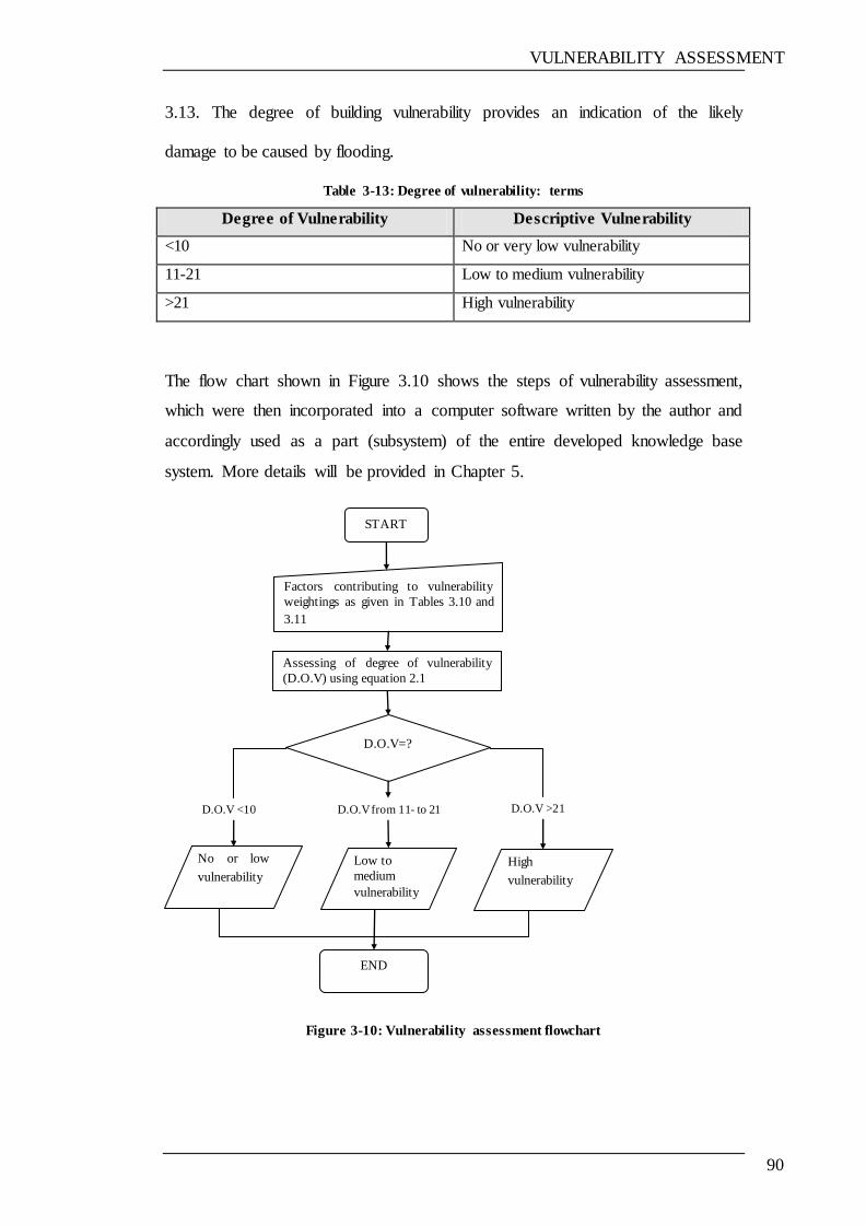
VULNERABILITY ASSESSMENT
90
3.13. The degree of building vulnerability provides an indication of the likely
damage to be caused by flooding.
Table 3-13: Degree of vulnerability: terms
Degree of Vulnerability Descriptive Vulnerability
<10 No or very low vulnerability
11-21 Low to medium vulnerability
>21 High vulnerability
The flow chart shown in Figure 3.10 shows the steps of vulnerability assessment,
which were then incorporated into a computer software written by the author and
accordingly used as a part (subsystem) of the entire developed knowledge base
system. More details will be provided in Chapter 5.
Figure 3-10: Vulnerability assessment flowchart
High
vulnerability
Low to
medium
vulnerability
No or low
vulnerability
START
Factors contributing to vulnerability
weightings as given in Tables 3.10 and
3.11
Assessing of degree of vulnerability
(D.O.V) using equation 2.1
D.O.V=?
END
D.O.V from 11- to 21 D.O.V >21 D.O.V <10
VULNERABILITY ASSESSMENT
91
3.5 SUMMARY
This chapter focused on the concept and assessment of vulnerability, with
examples. It also discussed the proposed model that was developed in order to
calculate the degree of vulnerability of buildings to flood damage. Moreover,
there are differences in vulnerability, and a variety of definitions distinguishing
between different vulnerabilities. With this in mind, the proposed model has been
developed on the basis of various definitions and the different vulnerability
assessment methods used to calculate geohazard risks. The model is based on the
weighting and rating of factors which are known to contribute to flood damage,
and a simple mathematical equation has been used to calculate the degree of
vulnerability.
The next chapter reviews two topics: flood damage management and knowledge-
based systems.
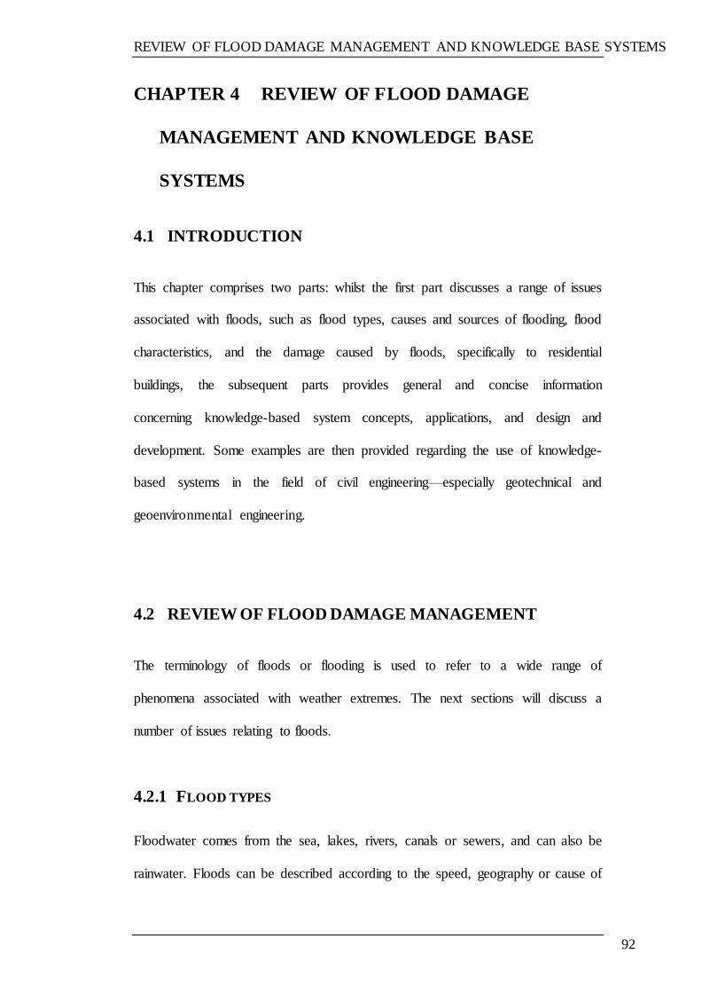
REVIEW OF FLOOD DAMAGE MANAGEMENT AND KNOWLEDGE BASE SYSTEMS
92
CHAPTER 4 REVIEW OF FLOOD DAMAGE
MANAGEMENT AND KNOWLEDGE BASE
SYSTEMS
4.1 INTRODUCTION
This chapter comprises two parts: whilst the first part discusses a range of issues
associated with floods, such as flood types, causes and sources of flooding, flood
characteristics, and the damage caused by floods, specifically to residential
buildings, the subsequent parts provides general and concise information
concerning knowledge-based system concepts, applications, and design and
development. Some examples are then provided regarding the use of knowledge-
based systems in the field of civil engineering—especially geotechnical and
geoenvironmental engineering.
4.2 REVIEW OF FLOOD DAMAGE MANAGEMENT
The terminology of floods or flooding is used to refer to a wide range of
phenomena associated with weather extremes. The next sections will discuss a
number of issues relating to floods.
4.2.1 FLOOD TYPES
Floodwater comes from the sea, lakes, rivers, canals or sewers, and can also be
rainwater. Floods can be described according to the speed, geography or cause of
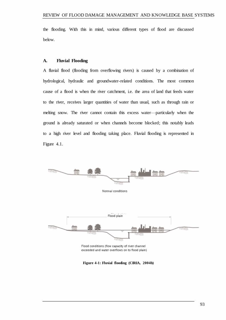
REVIEW OF FLOOD DAMAGE MANAGEMENT AND KNOWLEDGE BASE SYSTEMS
93
the flooding. With this in mind, various different types of flood are discussed
below.
A. Fluvial Flooding
A fluvial flood (flooding from overflowing rivers) is caused by a combination of
hydrological, hydraulic and groundwater-related conditions. The most common
cause of a flood is when the river catchment, i.e. the area of land that feeds water
to the river, receives larger quantities of water than usual, such as through rain or
melting snow. The river cannot contain this excess water—particularly when the
ground is already saturated or when channels become blocked; this notably leads
to a high river level and flooding taking place. Fluvial flooding is represented in
Figure 4.1.
A.
B.
C.
D.
E.
F.
G.
H.
I.
Figure 4-1: Fluvial flooding (CIRIA, 2004b)
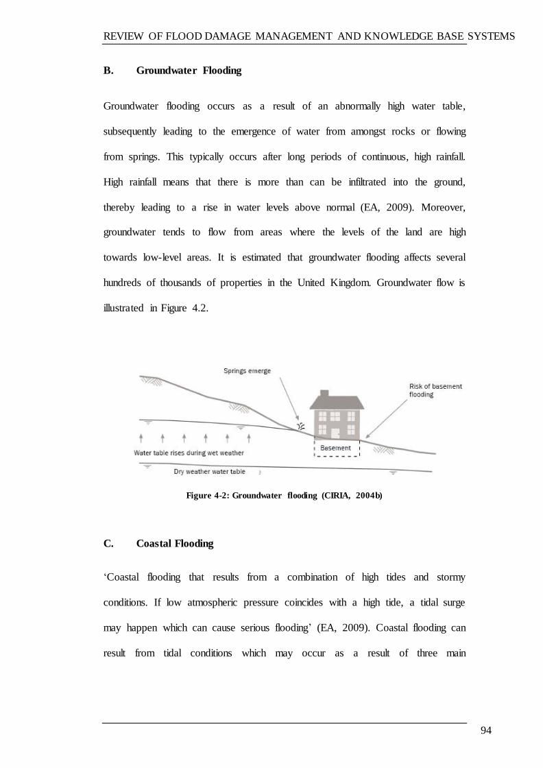
REVIEW OF FLOOD DAMAGE MANAGEMENT AND KNOWLEDGE BASE SYSTEMS
94
B. Groundwater Flooding
Groundwater flooding occurs as a result of an abnormally high water table,
subsequently leading to the emergence of water from amongst rocks or flowing
from springs. This typically occurs after long periods of continuous, high rainfall.
High rainfall means that there is more than can be infiltrated into the ground,
thereby leading to a rise in water levels above normal (EA, 2009). Moreover,
groundwater tends to flow from areas where the levels of the land are high
towards low-level areas. It is estimated that groundwater flooding affects several
hundreds of thousands of properties in the United Kingdom. Groundwater flow is
illustrated in Figure 4.2.
Figure 4-2: Groundwater flooding (CIRIA, 2004b)
C. Coastal Flooding
‗Coastal flooding that results from a combination of high tides and stormy
conditions. If low atmospheric pressure coincides with a high tide, a tidal surge
may happen which can cause serious flooding‘ (EA, 2009). Coastal flooding can
result from tidal conditions which may occur as a result of three main

REVIEW OF FLOOD DAMAGE MANAGEMENT AND KNOWLEDGE BASE SYSTEMS
95
mechanisms, with flooding most commonly associated with a combination of two
or more of these (CIRIA, 2004b):
High astronomical tide level: cyclical variation in tide levels owing to the
gravitational effects of (mainly) the sun and moon;
Surge: an increase in water level above the astronomical tide level caused
by low barometric pressure exacerbated by the wind acting on the surface
of the sea; and
Wave action: dependent on wind speed and direction, local topography
and exposure.
D. Overland Flow Flooding
Overland flow is caused when rainfall intensity exceeds the infiltration capacity of
the surface on which it falls, or otherwise when, during long periods of wet
weather, the soil becomes so saturated that it cannot accept more water(Samwinga,
Proverbs, and Homan,2004). Figure 4.3 illustrates overland flow flooding.
Figure 4-3: Overland flow flooding (CIRIA, 2004b)
REVIEW OF FLOOD DAMAGE MANAGEMENT AND KNOWLEDGE BASE SYSTEMS
96
E. Flooding from Artificial Drainage Systems
During heavy rainfall, flooding from artificial drainage systems—such as pipes,
land drains, sewers and drainage channels, for example—may occur if the rainfall
event exceeds the capacity of the drainage system, as shown in Figure 4.4.
Figure 4-4: Flooding from artificial drainage systems (CIRIA, 2004b)
F. Flooding from Infrastructure Failure
Where infrastructure exists that retains, transmits or controls the flow of water,
flooding may result if there is a structural, hydraulic, geotechnical, mechanical or
operational failure. The risk of this mechanism of flooding is associated with three
main categories of infrastructure (CIRIA, 2004b):
Failure of infrastructure designed to store or carry water (e.g. dam break,
canal leak, water mains burst);
Failure of infrastructure designed to protect an area from flooding;
Blockage of a pipe, bridge or culvert.
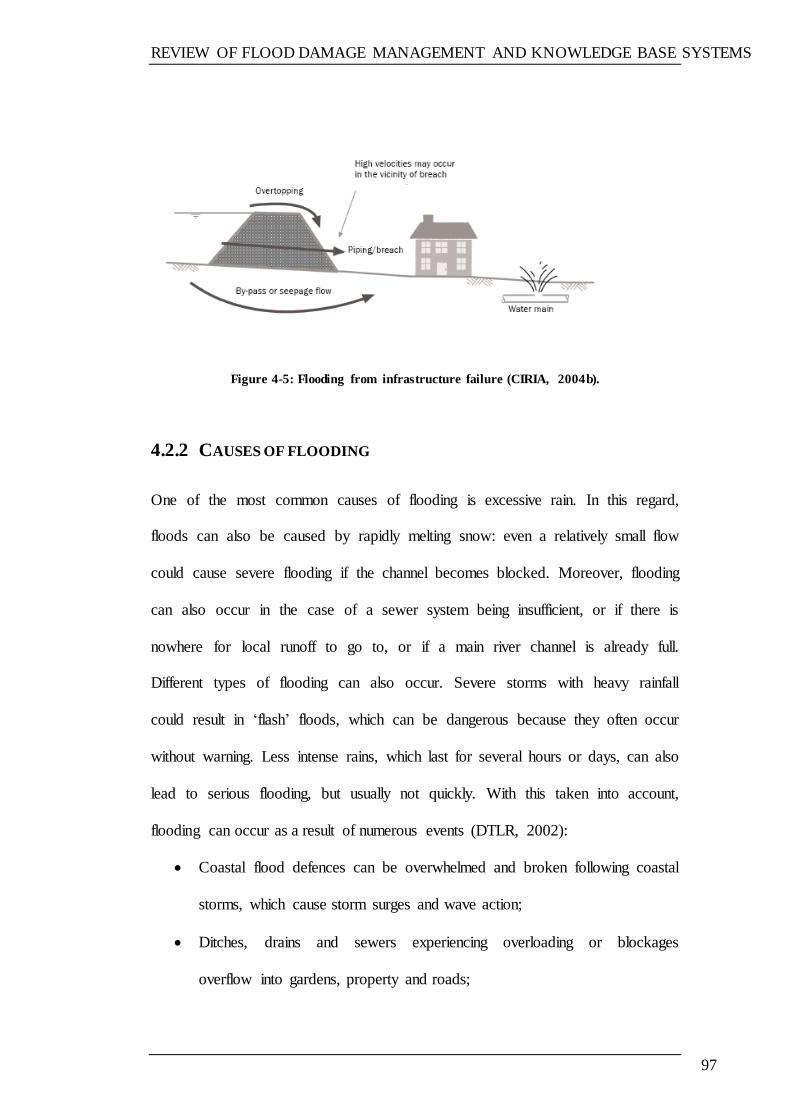
REVIEW OF FLOOD DAMAGE MANAGEMENT AND KNOWLEDGE BASE SYSTEMS
97
Figure 4-5: Flooding from infrastructure failure (CIRIA, 2004b).
4.2.2 CAUSES OF FLOODING
One of the most common causes of flooding is excessive rain. In this regard,
floods can also be caused by rapidly melting snow: even a relatively small flow
could cause severe flooding if the channel becomes blocked. Moreover, flooding
can also occur in the case of a sewer system being insufficient, or if there is
nowhere for local runoff to go to, or if a main river channel is already full.
Different types of flooding can also occur. Severe storms with heavy rainfall
could result in ‗flash‘ floods, which can be dangerous because they often occur
without warning. Less intense rains, which last for several hours or days, can also
lead to serious flooding, but usually not quickly. With this taken into account,
flooding can occur as a result of numerous events (DTLR, 2002):
Coastal flood defences can be overwhelmed and broken following coastal
storms, which cause storm surges and wave action;
Ditches, drains and sewers experiencing overloading or blockages
overflow into gardens, property and roads;
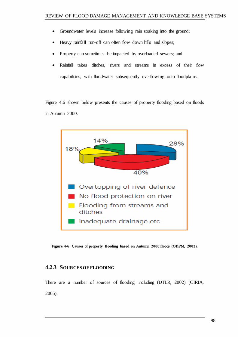
REVIEW OF FLOOD DAMAGE MANAGEMENT AND KNOWLEDGE BASE SYSTEMS
98
Groundwater levels increase following rain soaking into the ground;
Heavy rainfall run-off can often flow down hills and slopes;
Property can sometimes be impacted by overloaded sewers; and
Rainfall takes ditches, rivers and streams in excess of their flow
capabilities, with floodwater subsequently overflowing onto floodplains.
Figure 4.6 shown below presents the causes of property flooding based on floods
in Autumn 2000.
Figure 4-6: Causes of property flooding based on Autumn 2000 floods (ODPM, 2003).
4.2.3 SOURCES OF FLOODING
There are a number of sources of flooding, including (DTLR, 2002) (CIRIA,
2005):
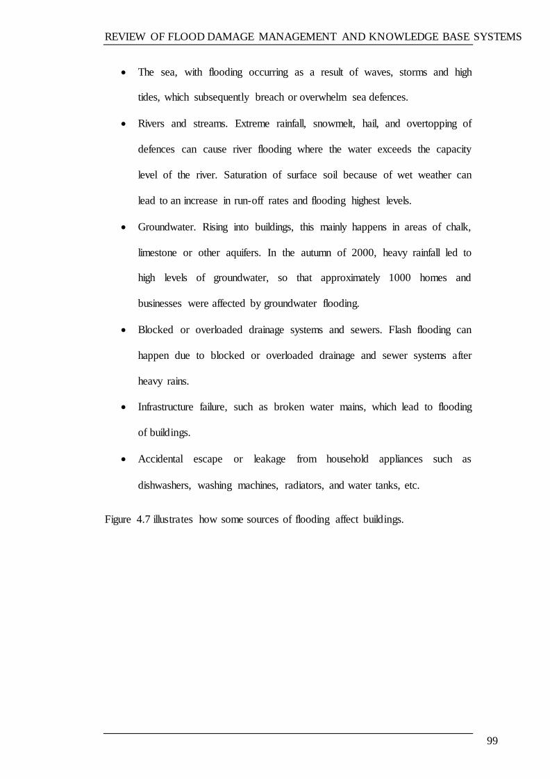
REVIEW OF FLOOD DAMAGE MANAGEMENT AND KNOWLEDGE BASE SYSTEMS
99
The sea, with flooding occurring as a result of waves, storms and high
tides, which subsequently breach or overwhelm sea defences.
Rivers and streams. Extreme rainfall, snowmelt, hail, and overtopping of
defences can cause river flooding where the water exceeds the capacity
level of the river. Saturation of surface soil because of wet weather can
lead to an increase in run-off rates and flooding highest levels.
Groundwater. Rising into buildings, this mainly happens in areas of chalk,
limestone or other aquifers. In the autumn of 2000, heavy rainfall led to
high levels of groundwater, so that approximately 1000 homes and
businesses were affected by groundwater flooding.
Blocked or overloaded drainage systems and sewers. Flash flooding can
happen due to blocked or overloaded drainage and sewer systems after
heavy rains.
Infrastructure failure, such as broken water mains, which lead to flooding
of buildings.
Accidental escape or leakage from household appliances such as
dishwashers, washing machines, radiators, and water tanks, etc.
Figure 4.7 illustrates how some sources of flooding affect buildings.
REVIEW OF FLOOD DAMAGE MANAGEMENT AND KNOWLEDGE BASE SYSTEMS
100
Figure 4-7: Some sources of flooding (CIRIA, 2004b)
4.3 FLOOD RISK IN THE UK
In England, more than 5% of the population lives less than 5 metres above sea
level. It is also stated that approximately 7% of the country is likely to flood at
least once every 100 years from rivers. In addition, almost 30% of the coasts are
developed with about 1.5% of the country at risk from coastal flooding (Office of
the Deputy Prime Minister, 2003).
Importantly, some 2.1 million homes in the whole of the UK are in areas which
are considered to be at risk from river and sea flooding. Notably, 48.5% of these
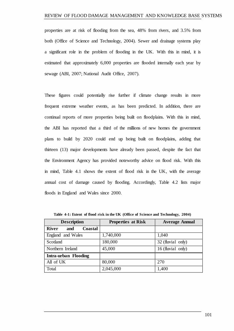
REVIEW OF FLOOD DAMAGE MANAGEMENT AND KNOWLEDGE BASE SYSTEMS
101
properties are at risk of flooding from the sea, 48% from rivers, and 3.5% from
both (Office of Science and Technology, 2004). Sewer and drainage systems play
a significant role in the problem of flooding in the UK. With this in mind, it is
estimated that approximately 6,000 properties are flooded internally each year by
sewage (ABI, 2007; National Audit Office, 2007).
These figures could potentially rise further if climate change results in more
frequent extreme weather events, as has been predicted. In addition, there are
continual reports of more properties being built on floodplains. With this in mind,
the ABI has reported that a third of the millions of new homes the government
plans to build by 2020 could end up being built on floodplains, adding that
thirteen (13) major developments have already been passed, despite the fact that
the Environment Agency has provided noteworthy advice on flood risk. With this
in mind, Table 4.1 shows the extent of flood risk in the UK, with the average
annual cost of damage caused by flooding. Accordingly, Table 4.2 lists major
floods in England and Wales since 2000.
Table 4-1: Extent of flood risk in the UK (Office of Science and Technology, 2004)
Description Properties at Risk
(number)
Average Annual
Damage (£ millions) River and Coastal
Flooding
England and Wales 1,740,000 1,040
Scotland 180,000 32 (fluvial only)
Northern Ireland 45,000 16 (fluvial only)
Intra-urban Flooding
All of UK 80,000 270
Total 2,045,000 1,400

REVIEW OF FLOOD DAMAGE MANAGEMENT AND KNOWLEDGE BASE SYSTEMS
102
Table 4-2: Major floods in England and Wales since 2000
Date Area affected and features of the event
Autumn 2000 More than 10,000 properties were flooded in England and Wales. (ABI, 2005)
August 16, 2004
(Boscastle)
Flash floods, 100 homes and businesses were flooded.
(Environment Agency )
January 8–9, 2005
(Carlisle)
1,700 homes and 300 businesses were flooded.
(ABI, 2005)
Summer 2007 Claimed 14 lives. More than 49,000 homes and 7,000
businesses flooded, roads closed included M1, M4, M5, M18, M40 and M50. (ABI, 2007)
November 2009
(Cumbria)
36,000 flood and storm damage claims totalling an
estimated £206 million, with 60% of the sum relating to business damage. (ABI, 2010a)
In England and Wales, the areas at risk from flooding have been mapped
according to what are known as Indicative Floodplain Maps (IFM), which is
available on the Environment Agency website.
Notably, flood risk has always been present for buildings near coasts, rivers or
watercourses, and it has since become clear during recent years that much of the
property stock in the UK has been at risk of a flood event. Markedly, the flood
risk for a property can generally be defined as a combination of the possibility of a
flood happening and the consequences of the flood in terms of damage caused or
its impact (DTLR, 2002; ABI ,2008).
REVIEW OF FLOOD DAMAGE MANAGEMENT AND KNOWLEDGE BASE SYSTEMS
103
In the autumn of 2000, 11,000 homes were flooded. During the New Year period
of 2003, 1,200 properties were flooded in central and southern England. More
recently, during June, 2007, there were a number of flood events in various parts
of Northern Ireland, North Yorkshire, the Midlands, Gloucestershire and
Worcestershire. Six people died in the floods, and damage to commercial property
was estimated to have reached £1 billion, with 5,000 businesses and 27,000
houses affected. Moreover, two million homes and 185,000 businesses are at risk
of flooding in both England and Wales (Crichton, 2003; Environment, Food and
Rural Affairs Committee, 2008).
Without question, flood danger is always present, affecting people and property
near the coasts and rivers or waterways. However, during recent years, it has
become clear that the risks and consequences of flood events have become a
reality for more properties. With this in mind, it is noteworthy to emphasise that
flood risk in the UK are likely to continue to increase, and actual floods become
more frequent, widespread and costly, owing to a number of factors combined,
these including (Broadbent, 2004; RMS, 2001; United Nations University, 2004;
Dyer,2004):
Development on floodplains, with plans for construction of up to three
million more homes by 2016;
Recent under-investment in the maintenance of local flood defences;
Potential increases in risk due to climate variability which will cause
heavy rains and raise sea levels, leading to an increased flood risk;
Lack of maintenance of drainage and flood-fighting systems; and
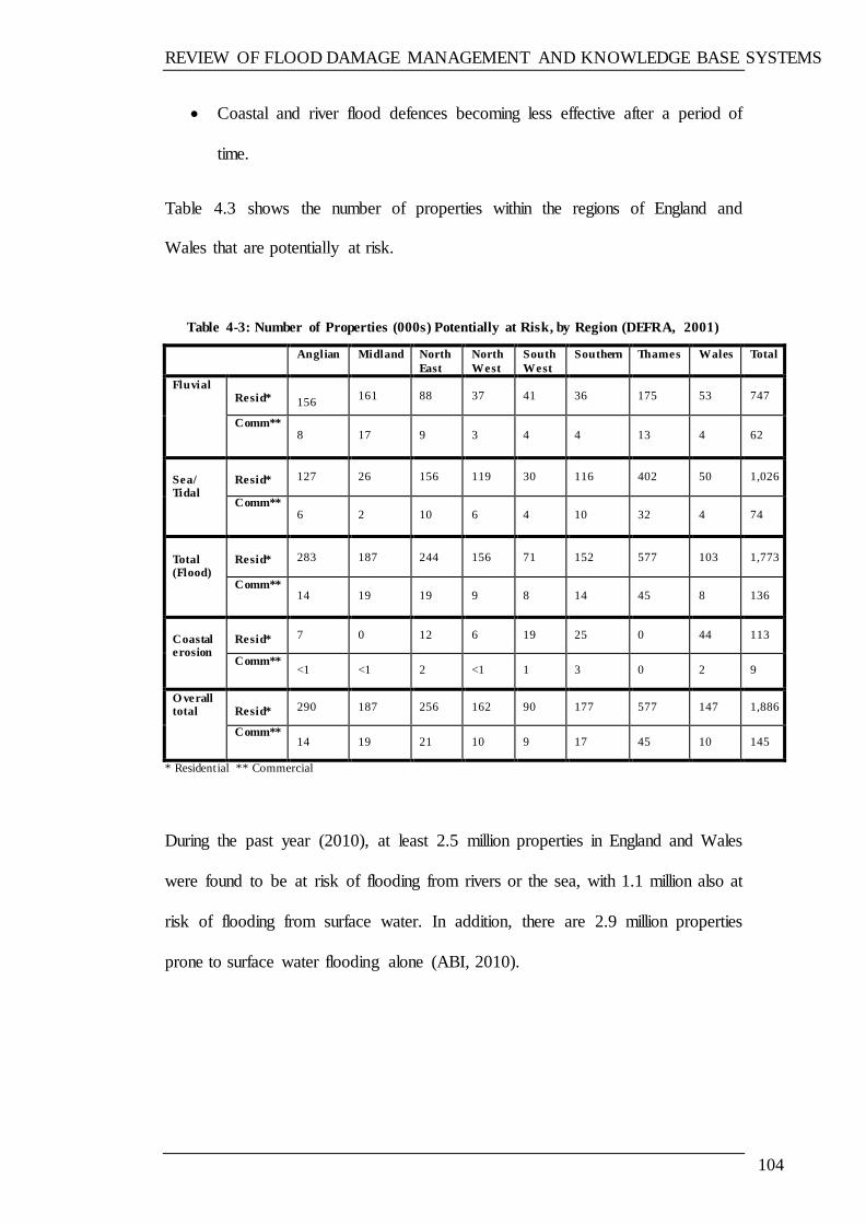
REVIEW OF FLOOD DAMAGE MANAGEMENT AND KNOWLEDGE BASE SYSTEMS
104
Coastal and river flood defences becoming less effective after a period of
time.
Table 4.3 shows the number of properties within the regions of England and
Wales that are potentially at risk.
Table 4-3: Number of Properties (000s) Potentially at Risk, by Region (DEFRA, 2001)
Anglian Midland North
East
North
West
South
West
Southern Thames Wales Total
Fluvial Resid*
156
161 88 37 41 36 175 53 747
Comm** 8
17 9 3 4 4 13 4 62
Sea/ Tidal
Resid* 127 26 156 119 30 116 402 50 1,026
Comm** 6 2 10 6 4 10 32 4 74
Total (Flood)
Resid* 283 187 244 156 71 152 577 103 1,773
Comm** 14 19 19 9 8 14 45 8 136
Coastal erosion
Resid* 7 0 12 6 19 25 0 44 113
Comm** <1 <1 2 <1 1 3 0 2 9
O verall total
Resid* 290 187 256 162 90 177 577 147 1,886
Comm** 14 19 21 10 9 17 45 10 145
* Residential ** Commercial
During the past year (2010), at least 2.5 million properties in England and Wales
were found to be at risk of flooding from rivers or the sea, with 1.1 million also at
risk of flooding from surface water. In addition, there are 2.9 million properties
prone to surface water flooding alone (ABI, 2010).
REVIEW OF FLOOD DAMAGE MANAGEMENT AND KNOWLEDGE BASE SYSTEMS
105
4.4 FLOOD DAMAGE TO BUILDINGS
Flood damage can range from minor, with small amounts of water entering the
building, through to more severe cases, where extensive damage occurs. The
amount of damage depends on the depth and duration of flooding (DTLR, 2002).
Importantly, flooding that causes significant damage to residential buildings
essentially depends on the depth of the flood. In this regard, floodwater can enter
unprotected buildings through several routes, including (EA, 2003):
Around closed doors and windows, mainly via the joints between frames
and walls;
Through gaps around services which enter the property, e.g. pipes for gas,
water and sewerage, electricity, telephone and television cables, and vents
for central heating systems, washing machines, etc.;
Directly through the walls of the property;
Some bricks, blocks, stones and mortar used in buildings and floodwater
will seep through them due to their natural permeability;
Through cracks in the walls;
Through party walls shared with the property next door, in the case of
semi-detached or terraced houses;
Via joints between building elements, such as expansion joints between
walls, at positions where different construction materials meet or between
the floor slab and wall;
Through gaps in masonry, stonework and blockwork walls, where mortar
has been omitted during the construction of the building; and
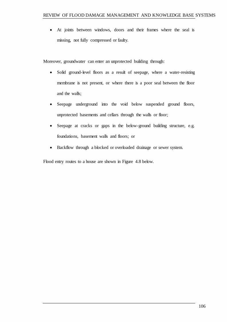
REVIEW OF FLOOD DAMAGE MANAGEMENT AND KNOWLEDGE BASE SYSTEMS
106
At joints between windows, doors and their frames where the seal is
missing, not fully compressed or faulty.
Moreover, groundwater can enter an unprotected building through:
Solid ground-level floors as a result of seepage, where a water-resisting
membrane is not present, or where there is a poor seal between the floor
and the walls;
Seepage underground into the void below suspended ground floors,
unprotected basements and cellars through the walls or floor;
Seepage at cracks or gaps in the below-ground building structure, e.g.
foundations, basement walls and floors; or
Backflow through a blocked or overloaded drainage or sewer system.
Flood entry routes to a house are shown in Figure 4.8 below.
REVIEW OF FLOOD DAMAGE MANAGEMENT AND KNOWLEDGE BASE SYSTEMS
107
Figure 4-8: Flood entry routes into a house (Environment Agency, 2003)
Kelman & Spence (2004) identify a set of potential effects which could be
experienced by houses as a result of floodwater, as follows:
Hydrostatic actions: these include the lateral and uplift pressure forces
owing to surrounding floodwater and saturated ground. Increased depth of
flooding leads to increased hydrostatic pressure.
Hydrodynamic actions: these are the effects on a building of
hydrodynamic forces owing to the flowing and movement of floodwater
around the building. These forces increase as the depth and velocity of
flooding increase.
REVIEW OF FLOOD DAMAGE MANAGEMENT AND KNOWLEDGE BASE SYSTEMS
108
Erosion actions: erosion can be caused by water flowing around the
building or by the actions of waves lapping at a building.
Buoyancy actions: buildings or components may exhibit buoyancy in
floodwater. These include oil and gas tanks and all elements that rely on
self-weight to ensure stability.
Debris actions: action from any debris contained in the floodwater. Can be
a static force, such as in the case of a building up of silt, or it could be a
dynamic effect from an object being propelled against the building.
Non-physical actions: building materials can be influenced by the
chemical composition of water. The floodwater may be saline or contain
contaminants such as sewage or chemicals.
Direct water contact: building materials can be affected by direct contact
with floodwater. For example, they may swell, crack or dissolve from
exposure to water.
4.4.1 FACTORS AFFECTING BUILDING FLOOD DAMAGE
Damage caused to a property is dependent on the characteristics of the flood, as
well as of the building itself. Flood characteristics include flood depth, velocity
flow, contaminant content and flood duration (Robby and Proverbs, 2004).
Notably, it is clear that the flood depth is the key factor controlling the damage
caused by the flood. In actual fact, the effect of the other factors remains unclear
since it is difficult to measure these, and there is also no clear data highlighting
the effect of such factors.
REVIEW OF FLOOD DAMAGE MANAGEMENT AND KNOWLEDGE BASE SYSTEMS
109
4.4.1.1 Flood characteristics
a) Flood Depth
Although buildings may be prone to flooding to different depths, deeper floods
occur less frequently than shallower ones. The flood depth at the building
structure can be calculated by determining the height of the flood elevation above
the ground level at the site of the building.
It is clear that floodwater depth is the key factor affecting the extent of the damage
caused by flooding. Very shallow flooding—such as where the water does not rise
above the ground level—is unlikely to be significant for most properties;
however, it should be remembered that, even in the incidence of shallow flooding,
water can still enter cellars, basements and spaces under decks, and can also cause
problems of moisture in the walls. Moreover, serious damage can occur when the
floodwater depth rises above the level of the floor, and also comes into contact
with inner surfaces, electrical sockets, equipment, kitchen cupboards, carpets,
furniture and personal belongings. Moreover, it is recognised that flood depths
greater than one metre above the floor level are more likely to result in structural
damage to the building (ODPM (2003).
According to Proverb & Soetanto (2004), the main characteristics of floods which
determine the degree of damage caused are the depth of the flood, the duration of
the flood, and the level of pollutants or other contaminants in the floodwater. As
the depth of the flood or its duration increases, there is then greater potential
damage to buildings (Figure 4.9). In their published report providing guidance on
preparing for floods (2002), the DTLR state that flood depth is the most important
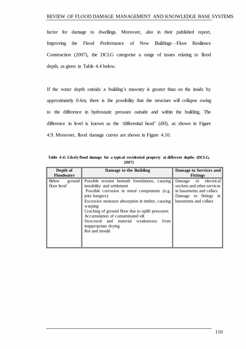
REVIEW OF FLOOD DAMAGE MANAGEMENT AND KNOWLEDGE BASE SYSTEMS
110
factor for damage to dwellings. Moreover, also in their published report,
Improving the Flood Performance of New Buildings—Floor Resilience
Construction (2007), the DCLG categorise a range of issues relating to flood
depth, as given in Table 4.4 below.
If the water depth outside a building‘s masonry is greater than on the inside by
approximately 0.6m, there is the possibility that the structure will collapse owing
to the difference in hydrostatic pressure outside and within the building. The
difference in level is known as the ‗differential head‘ (dH), as shown in Figure
4.9. Moreover, flood damage curves are shown in Figure 4.10.
Table 4-4: Likely flood damage for a typical residential property at different depths (DCLG,
2007)
Depth of
Floodwater
Damage to the Building Damage to Services and
Fittings
Below ground
floor level
Possible erosion beneath foundations, causing
instability and settlement
Possible corrosion in metal components (e.g.
joist hangers)
Excessive moisture absorption in timber, causing
warping
Cracking of ground floor due to uplift pressures
Accumulation of contaminated silt
Structural and material weaknesses from
inappropriate drying
Rot and mould
Damage to electrical
sockets and other services
in basements and cellars
Damage to fittings in
basements and cellars

REVIEW OF FLOOD DAMAGE MANAGEMENT AND KNOWLEDGE BASE SYSTEMS
111
Ground level to
half a metre
above floor level
Build-up of water and silt in cavity walls, with
potential reduction in insulating properties, for
some materials
Immersed floor insulation may tend to float and
cause screeds to debond
Damage to internal finishes, such as wall
coverings and plaster linings
Floors and walls may be affected to varying
degrees (e.g. swelling) and may require cleaning
and drying out
Timber-based materials likely to require
replacement
Damage to internal and external doors and
skirting boards
Corrosion of metal fixings
Rot and mould
Damage to water,
electricity and gas meters
Damage to low-level
boilers and some
underfloor heating
systems
Damage to
communication wiring
and services
Carpets and floor
coverings may need to be
replaced
Insulation on pipework
may need replacing
Half a metre and
above
Increased damage to walls (as above)
Differential heads of greater than 0.6m across
walls could cause structural damage, although
this will vary depending on the structure of the
building
Damage to windows can be caused by much
smaller differential pressures
High speed flow around the building‘s perimeter
can lead to erosion of the ground surface; there is
also the potential risk of damage to the structure
from large items of floating debris, e.g. tree
trunks
Damage to higher units,
electrical services and
appliances
Figure 4-9: Difference in water depth (dH) (DCLG and EA, 2007)
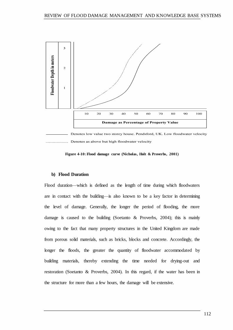
REVIEW OF FLOOD DAMAGE MANAGEMENT AND KNOWLEDGE BASE SYSTEMS
112
Figure 4-10: Flood damage curve (Nicholas, Holt & Proverbs, 2001)
b) Flood Duration
Flood duration—which is defined as the length of time during which floodwaters
are in contact with the building—is also known to be a key factor in determining
the level of damage. Generally, the longer the period of flooding, the more
damage is caused to the building (Soetanto & Proverbs, 2004); this is mainly
owing to the fact that many property structures in the United Kingdom are made
from porous solid materials, such as bricks, blocks and concrete. Accordingly, the
longer the floods, the greater the quantity of floodwater accommodated by
building materials, thereby extending the time needed for drying-out and
restoration (Soetanto & Proverbs, 2004). In this regard, if the water has been in
the structure for more than a few hours, the damage will be extensive.
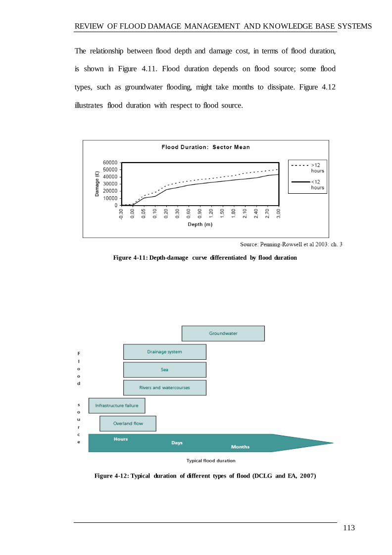
REVIEW OF FLOOD DAMAGE MANAGEMENT AND KNOWLEDGE BASE SYSTEMS
113
The relationship between flood depth and damage cost, in terms of flood duration,
is shown in Figure 4.11. Flood duration depends on flood source; some flood
types, such as groundwater flooding, might take months to dissipate. Figure 4.12
illustrates flood duration with respect to flood source.
Figure 4-11: Depth-damage curve differentiated by flood duration
Figure 4-12: Typical duration of different types of flood (DCLG and EA, 2007)
REVIEW OF FLOOD DAMAGE MANAGEMENT AND KNOWLEDGE BASE SYSTEMS
114
As discussed in the previous section, there are clear indications that flood
characteristics need to be considered in assessing damage to buildings due to
flooding. The damage caused by flooding is increased by an increase in flood
depth and duration and depends on the building materials.
4.4.1.2 Building characteristics
A building‘s characteristics constitute an important factor in assessing flood
damage. These include building type, the materials from which the building is
built, and their drying characteristics, building age, and the frequency with which
the building is flooded (Nicholas et al., 2001). Importantly, the majority of UK
properties are constructed from porous/permeable materials, such as bricks,
blocks, concrete, plaster and render. With this in mind, it is important to
acknowledge how these react following exposure to floodwater (Proverbs &
Soetanto, 2004).
Green & Suleman (1987) suggest that buildings which are frequently flooded
seem to suffer less damage than those which are flooded infrequently, simply
because the occupiers of the former will be more prepared and ready for any flood
events.
In addition, the condition of a building prior to being flooded is also an important
factor which is known to have a significant influence on flood damage (Proverbs
& Soetanto, 2004). For instance, a building which is not well repaired and
maintained will be affected more severely by flooding. With this in mind, it can
therefore be seen that the damage incurred through flooding can vary from being
either very minor or very severe, with the latter witnessed in the case of deep
REVIEW OF FLOOD DAMAGE MANAGEMENT AND KNOWLEDGE BASE SYSTEMS
115
floodwater causing notable damage to not only the building itself but also that
contained within.
Essentially, the degree of damage caused by a flood when it has been in contact
with building elements is dependent mainly on flood depth, the material type, and
other factors, as discussed previously. The building elements that might be in
contact with water during a flood event are discussed in the next section.
4.4.1.3 Damage caused by flooding to building elements
Floodwater can find its way into buildings through various different ways, as
mentioned in Section 4.4. The number of building elements that can be in contact
with floodwater depends mainly on the floodwater depth. For example, in shallow
floods, the walls might not be touched by the floodwater.
In general, the elements that might be damaged by flooding include foundations,
floors, walls (internal and external), windows and doors, sanitary ware, and
joinery and fittings. In addition, although it is known that flooding can damage
buildings in many different ways, the most common flood damage results from:
direct damage at the time of flooding, caused by high speed flows and
waves, erosion, or debris carried by the floodwater
damage caused to building materials due to contact with water during the
flood period and sometimes after.
The building elements that might be damaged and might need repair or
replacement include those detailed below. They are used as a basis for the
proposed system in damage assessment and selection of the repair options. There
REVIEW OF FLOOD DAMAGE MANAGEMENT AND KNOWLEDGE BASE SYSTEMS
116
is a subsystem that aims to assess the damage caused by flooding to the building
foundations and other subsystems can be used to suggest the repair options for the
other building elements. The next section presents different building elements,
including types and materials, that are used in the UK‘s residential buildings.
a) Building Foundations
Fast flowing floodwaters can affect a building‘s footings by removing
surrounding material, and thereby undermining the structure. In addition, it is
possible that some types of soil settle after flooding and produce structural
movements in the building‘s footings. In addition, foundation movements can
occur owing to slumping of sloping sites when affected by floodwater (CIRIA,
2004).
Generally, Foundation movement indications as follow (Driscoll & Skinner,
2007; Dickinson, and Thornton, 2004; Atkinson, 2004).
Cracks which show on both faces of a solid wall.
Cracks which show on both faces of a cavity wall - ie on the outside of the
outer leaf and the inside of the inner leaf.
Cracks which taper - either wide at the bottom or narrow at the top or vice
versa.
Distortion in door and window openings.
Walls out of plumb and ground floors out of level.
Cracks which run across (i.e. above and below) the DPC.
Broken drains or disrupted services.

REVIEW OF FLOOD DAMAGE MANAGEMENT AND KNOWLEDGE BASE SYSTEMS
117
There are three main types of foundations found in residential buildings (Glover ,
2006):
I. Victorian and prior foundations: these can be found in older buildings built
in the 19th Century and before. The technique was to dig a shallow trench
and lay a brick footing on the bed of hogging approximately 500mm
below the ground surface, as shown in Figure 4.13.
Figure 4-13: Victorian and prior foundations type (Glover, 2006)
II. 1930 domestic foundations comprises strips of concrete at a depth of more
than 450mm in order to protect the foundation from frost damage. Details
are given in Figure 4.14.

REVIEW OF FLOOD DAMAGE MANAGEMENT AND KNOWLEDGE BASE SYSTEMS
118
Figure 4-14: Typical 1930 domestic foundations type (Glover, 2006)
III. Modern short-bored pile foundations were founded in 1990, and comprise
reinforced beam placed of concrete columns piled four meters below the
surface soil on solid sub soil as given in Figure 4.15.
Figure 4-15: Modern short-bored pile foundations type (Glover, 2006)
REVIEW OF FLOOD DAMAGE MANAGEMENT AND KNOWLEDGE BASE SYSTEMS
119
b) Floors
Floors are one of the building elements that can be easily damaged as a result of
floodwater, even in the case of shallow flooding. The degree of damage caused by
floodwater depends on the type of floor. With this in mind, there are three
recognised types of floor, which are commonly applied in UK buildings:
suspended timber floors, solid concrete floors, and suspended concrete floors.
Suspended timber floors
Suspended timber floors are considered to be the most common form of
construction for the ground floors of existing houses in the UK, although they are
only used in a small proportion of newly constructed homes (Harris, 1995).
Moreover, suspended floors are usually made out of timber boards or waterproof
chipboard sheets fixed on top of joists. Figure 4.16 illustrates suspended timber
floor details and the issues to be considered in case of flood events.
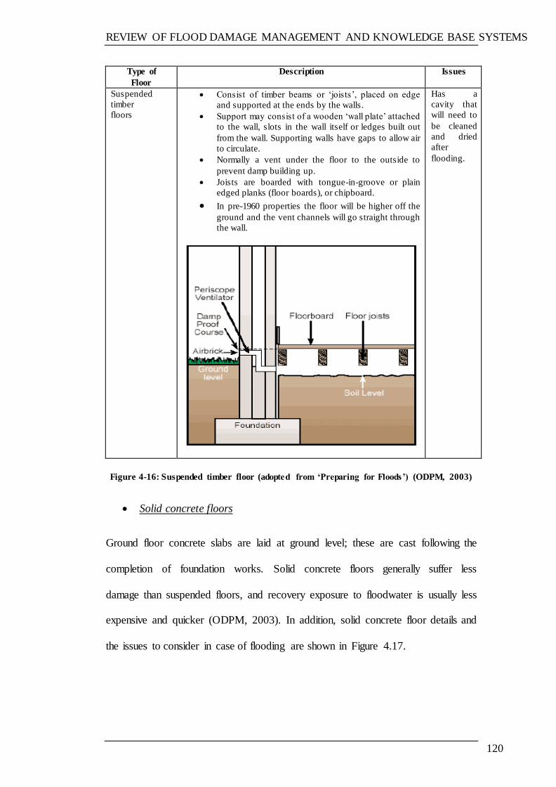
REVIEW OF FLOOD DAMAGE MANAGEMENT AND KNOWLEDGE BASE SYSTEMS
120
Type of
Floor
Description Issues
Suspended
timber
floors
Consist of timber beams or ‗joists‘, placed on edge
and supported at the ends by the walls.
Support may consist of a wooden ‗wall plate‘ attached
to the wall, slots in the wall itself or ledges built out
from the wall. Supporting walls have gaps to allow air
to circulate.
Normally a vent under the floor to the outside to
prevent damp building up.
Joists are boarded with tongue-in-groove or plain
edged planks (floor boards), or chipboard.
In pre-1960 properties the floor will be higher off the
ground and the vent channels will go straight through
the wall.
Has a
cavity that
will need to
be cleaned
and dried
after
flooding.
Figure 4-16: Suspended timber floor (adopted from ‘Preparing forFloods’) (ODPM, 2003)
Solid concrete floors
Ground floor concrete slabs are laid at ground level; these are cast following the
completion of foundation works. Solid concrete floors generally suffer less
damage than suspended floors, and recovery exposure to floodwater is usually less
expensive and quicker (ODPM, 2003). In addition, solid concrete floor details and
the issues to consider in case of flooding are shown in Figure 4.17.
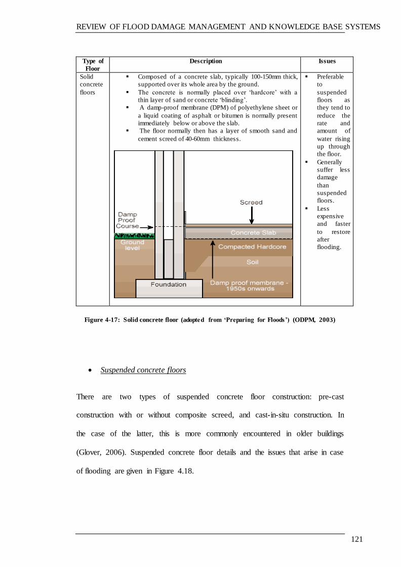
REVIEW OF FLOOD DAMAGE MANAGEMENT AND KNOWLEDGE BASE SYSTEMS
121
Type of
Floor
Description Issues
Solid
concrete
floors
Composed of a concrete slab, typically 100-150mm thick,
supported over its whole area by the ground.
The concrete is normally placed over ‗hardcore‘ with a
thin layer of sand or concrete ‗blinding‘.
A damp-proof membrane (DPM) of polyethylene sheet or
a liquid coating of asphalt or bitumen is normally present
immediately below or above the slab.
The floor normally then has a layer of smooth sand and
cement screed of 40-60mm thickness.
Preferable
to
suspended
floors as
they tend to
reduce the
rate and
amount of
water rising
up through
the floor.
Generally
suffer less
damage
than
suspended
floors.
Less
expensive
and faster
to restore
after
flooding.
Figure 4-17: Solid concrete floor (adopted from ‘Preparing forFloods’) (ODPM, 2003)
Suspended concrete floors
There are two types of suspended concrete floor construction: pre-cast
construction with or without composite screed, and cast-in-situ construction. In
the case of the latter, this is more commonly encountered in older buildings
(Glover, 2006). Suspended concrete floor details and the issues that arise in case
of flooding are given in Figure 4.18.

REVIEW OF FLOOD DAMAGE MANAGEMENT AND KNOWLEDGE BASE SYSTEMS
122
Type of
Floor
Description Issues
Suspended
concrete
floors
Modern floors (beam and block floors) use precast concrete beams
set on sleeper walls at the damp-proof course level, infilled with
concrete blocks.
Has a
cavity
that will
need to
be
cleaned
and
dried
Figure 4-18: Suspended concrete floor (adopted from ‘Preparing forFloods' (ODPM, 2003)
c) Walls
There are three common types of wall construction in UK dwellings:
Cavity walls with bricks and/or blocks;
Solid brick or masonry walls; and
Timber framed walls.
Figure 4.19 gives details of each type, and the issues that arise in case of flood
events.

REVIEW OF FLOOD DAMAGE MANAGEMENT AND KNOWLEDGE BASE SYSTEMS
123
Figure 4-19: Wall types (CIRIA, 2003b, Advice sheet 4)
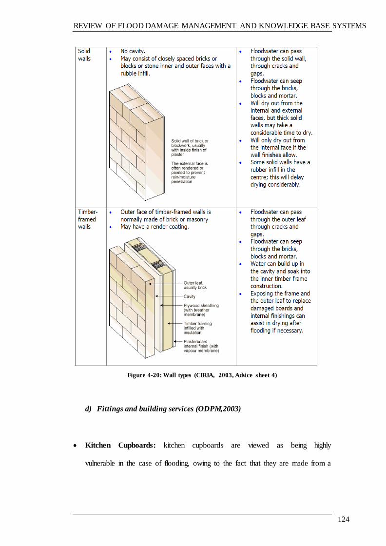
REVIEW OF FLOOD DAMAGE MANAGEMENT AND KNOWLEDGE BASE SYSTEMS
124
Figure 4-20: Wall types (CIRIA, 2003, Advice sheet 4)
d) Fittings and building services (ODPM,2003)
Kitchen Cupboards: kitchen cupboards are viewed as being highly
vulnerable in the case of flooding, owing to the fact that they are made from a
REVIEW OF FLOOD DAMAGE MANAGEMENT AND KNOWLEDGE BASE SYSTEMS
125
combination of MDF and chipboard, with plastic coverings. With this in mind,
such units will need to be replaced following flooding and internal damage.
Kitchen Appliances: all appliances susceptible to flooding—both gas and
electric—will need to be thoroughly inspected by a professional before they
are reused.
Bathrooms: flooding commonly affects bathrooms, including hand basins and
toilets. In addition, owing to their chipboard base, baths are also vulnerable to
floodwater, which will therefore need to be replaced following exposure to
such.
Doors: both internal and external doors are made from different materials,
including aluminium, PVCu and timber. Accordingly, some doors are more
likely to be damaged following flooding than others: for example, more solid
doors are less likely to be vulnerable whilst hollow doors are more open to
damage. Moreover, fire doors, which are usually made from fire-resistant
materials, can be damaged should there be exposure to floodwater.
Timber doors: upon exposure to flooding, hollow timber doors commonly
de-laminate, which therefore necessitates replacement.
Timber windows: following floodwater exposure, wooden window frames
may warp and distort, therefore necessitating replacement. Furthermore,
windows made from other materials—including aluminium and PVCu—
commonly have hollow section, which may therefore become filled with
floodwater, and cause problems when draining.
Staircases: flooding may only affect solid timber staircases to a minor extent.
REVIEW OF FLOOD DAMAGE MANAGEMENT AND KNOWLEDGE BASE SYSTEMS
126
Electricity supply: floodwater can cause notable damage to both electric
meters and fuse boxes, owing to the fact that they are within the house and
located at low levels.
Wiring and sockets: floodwater can affect sockets at low levels.
Gas supply: gas systems may be affected by water and silt, which affect their
overall functionality. Moreover, gas meters may also be damaged through
flooding.
Central heating systems: a professional will need to inspect and approve the
use of gas and oil fire boilers, as well as all associated controls, fittings and
pumps exposed to flooding. These items may need to be replaced.
Storage Heaters: floodwater can also damage electrical storage heaters,
therefore necessitating their replacement.
Water supply: flooding generally does not affect water meters and pipes,
although it is recognised that some damage may be noted in the case of pipe
insulation tubes.
Importantly, time is recognised as an important element for consideration when
seeking to determine the degree of damage incurred as a result of flooding.
Notably, when the elements in question have been in contact with water for more
than a few hours, it is recognised that damage may be significant and costly, as
can be recognised when considering walls and ceilings, electrical appliances, and
flooring, all of which will experience high levels of damage following exposure to
water.
The flood damage scenario is based on two main factors: the characteristics of the
building, and the characteristics of the flood. Different scenarios could occur that
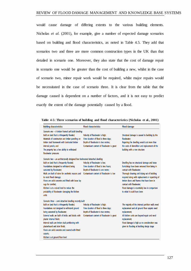
REVIEW OF FLOOD DAMAGE MANAGEMENT AND KNOWLEDGE BASE SYSTEMS
127
would cause damage of differing extents to the various building elements.
Nicholas et al. (2001), for example, give a number of expected damage scenarios
based on building and flood characteristics, as noted in Table 4.5. They add that
scenarios two and three are more common construction types in the UK than that
detailed in scenario one. Moreover, they also state that the cost of damage repair
in scenario one would be greater than the cost of building a new, whilst in the case
of scenario two, minor repair work would be required, whilst major repairs would
be necessitated in the case of scenario three. It is clear from the table that the
damage caused is dependent on a number of factors, and it is not easy to predict
exactly the extent of the damage potentially caused by a flood.
Table 4-5: Three scenarios of building and flood characteristics (Nicholas et al., 2001)
REVIEW OF FLOOD DAMAGE MANAGEMENT AND KNOWLEDGE BASE SYSTEMS
128
4.5 DAMAGE REPAIR OF FLOODED BUILDINGS
Association of British insurer (2009) estimate the average costs for building
restoration to be approximately £25,000.
Notably, the majority of properties in flood zones in the United Kingdom are
insured by private insurance companies; these agencies provide general policies
under which the cost of flood damage restoration is included in the standard
policy and is not costed separately in the sense that the property owner might
otherwise have to pay an extra cost for reinstatement of his property. Moreover,
the level of cover offered by insurance providers is different from one company to
another.
4.5.1 MANAGEMENT OF DAMAGE TO FLOODED RESIDENTIAL
BUILDINGS
The general steps of the repair process flow for repairing a building damaged by
flooding are shown in Figure 4.20. Furthermore, it is noteworthy to recognise that,
in most cases, the issues relating to flooded building damage repair are raised
during the repair stage, as discussed in the next sections.

REVIEW OF FLOOD DAMAGE MANAGEMENT AND KNOWLEDGE BASE SYSTEMS
129
Figure 4-21: Repair process for a flooded building (CIRIA, 2005)
As mentioned in Figure 4-21 above, one of the main steps in the repair process is
the selection of standards required for the repair. The existence of a knowledge
base system that can help in the selection of the repair options will reduce the time
and the cost required for the repair.
Make safe the building for further work, complete a
health and safety risk assessment
Undertake the drying-out of the building
Decontaminate the building
Undertake a post-flood survey of material and
structural damage
Complete the post-flood risk assessment to inform on
requirements for standards of repair
Determine the standards required for the repair
Carry out repairs to the chosen standard

REVIEW OF FLOOD DAMAGE MANAGEMENT AND KNOWLEDGE BASE SYSTEMS
130
4.5.2 ISSUES IN FLOOD REPAIR AND THE NEED TO ESTABLISH
REPAIR STANDARDS
4.5.2.1 Issues in flood repair
There are a number of issues which can arise during the repair stage; these can be
identified as:
The property owners are not satisfied with the performance of a particular
contractor and/or insurance company. In a presentation by Paul Hendy
during the Workshop on Identification and Dissemination of Good
Practice in Flood Repair, held on Wednesday, March 15, 2006 at
Wolverhampton University, reference was made to a survey relating to the
experience of victims of the Carlisle flood event in 2005. Notably, it was
highlighted that, on a scale where the worst contractors were scored at 3%
and below, the three lowest scoring contractors were all employed by one
insurance company. The insurance company itself subsequently scored 8%
for customer satisfaction. The highest scoring contractor (Rameses at
98%) was employed by only one insurance company, namely Lloyds TSB,
which was, itself, the highest scoring insurance company at 76%. The
second highest (Norwich Union) scored 37% and the third (AXA) scored
21%. He also added that neighbours with similar properties and policies
had different repair works done; this means that, in practice, there is still
considerable diversity between the best and the worst in terms of
reinstatement.
Lamond (2008) adds two factors based to a questionnaire survey of
recently flooded insured homeowners, namely:
REVIEW OF FLOOD DAMAGE MANAGEMENT AND KNOWLEDGE BASE SYSTEMS
131
1. Cost of cover not related to risk; and
2. Lack of fairness, including
Different standards pursued by different companies;
Flood repairs funded by those not at risk via higher
premiums.
Importantly, there is a great deal of knowledge available concerning the
impacts of floods on various construction materials, as well as relating to
the best ways in which the process of restoration can be addressed. This
knowledge is held by several specialised flood repair companies, although
a large proportion of reinstatement work is carried out by general builders,
all of whom may have a limited understanding of even the basics—such as
the most effective ways of drying out a building and its contents (Lamond,
2008).
Inclusion (or not) of resilient repair as an option is one of the more
contentious issues in flood repair and building reinstatement. When
resilient repair is provided as an option, it is not generally taken up unless
the buildings are subject to frequent flooding (Lamond, 2008). In addition,
loss adjusters often recommend the cheapest reinstatement option as an
alternative to the ideal or resilient option, this being done to meet the
wishes of their insurance companies (Proverbs & Soetanto, 2004).
4.5.2.2 The need to establish repair standards
It is clear that there is a need to establish repair standards—or to at least produce
general guides to help building repair contractors to establish acceptable repair
strategies. Flood damage assessment is, at the present time, a function of
REVIEW OF FLOOD DAMAGE MANAGEMENT AND KNOWLEDGE BASE SYSTEMS
132
surveyors‘ perceptions. Owing to the fact that they do not have a standard set of
guidelines for the assessment of flood damage or recommended repair options,
there are therefore significant differences between their decisions (Nicholas et al.,
2001; EA2011).
Nevertheless, there are a few publications which cover the subject of
standardisation of flooded building repairs, such as:
Flood Damaged Property: A guide to repair (Proverbs and Soetanto,
2004).
A Guide to the Investigation and Repair of Flood Damage to Housing and
Small Businesses (Flood Repairs Forum, 2006).
Standards for the Repair of Buildings following Flooding (CIRIA, 2005).
The aforementioned guides recommended flood-resistant repairs of different
building elements. In this regard, they state that the value of having repair
standards is that they:
Help to establish reinstatement repair strategies with not too much
variance;
Increase satisfaction (Lamond, 2008);
Allow better underwriting decisions (Lamond, 2008);
Promote fairness (Lamond, 2008);
Maintain property values (Lamond, 2008); and
Potentially promote resilience (ABI, 2003).
4.5.3 FLOODED BUILDING DAMAGE REPAIR OPTIONS
Every house is different, and the selection of the most appropriate repair approach
REVIEW OF FLOOD DAMAGE MANAGEMENT AND KNOWLEDGE BASE SYSTEMS
133
depends on many factors; these include the flood risk, frequency and depth of
flooding, type of floodwater, construction and condition of the fabric of the
building, and the cost of repairs compared with the potential saving in the event of
subsequent floods (Broadbent, 2004). With this in mind, there are two repair
options available (non-resilient and resilient), and the selection of these options
differ in relation to damage in each case. Details of non-resilient and resilient
repair options will be given in Chapter 5.
4.5.3.1 Resilient remediation option
In 2007, the Ministry of Communities and Local Government issued a report
entitled ‗Improving the Flood Performance of New Buildings: Flood resilient
construction.‘ It aims to provide guidance to developers and designers concerning
how to improve the flood resilience of new properties built in flood risk areas. The
report defines resilience as ‗building in such a way that, although floodwater may
enter a building, its impact is reduced‘.
A comprehensive review was conducted by Pitt following severe flooding in the
UK in 2007, when 55,000 properties were damaged. The review included 92
recommendations, including:
Building Regulations should be revised to ensure that all new or
refurbished buildings in high flood risk areas are flood resistant or
resilient;
All local authorities should extend eligibility for home improvement
grants and loans to include flood resistance and resilience products for
properties in high flood risk areas; and
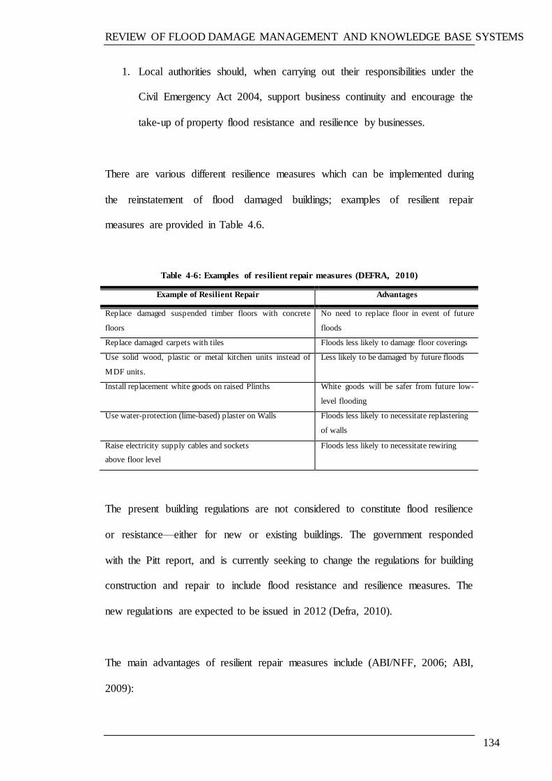
REVIEW OF FLOOD DAMAGE MANAGEMENT AND KNOWLEDGE BASE SYSTEMS
134
1. Local authorities should, when carrying out their responsibilities under the
Civil Emergency Act 2004, support business continuity and encourage the
take-up of property flood resistance and resilience by businesses.
There are various different resilience measures which can be implemented during
the reinstatement of flood damaged buildings; examples of resilient repair
measures are provided in Table 4.6.
Table 4-6: Examples of resilient repair measures (DEFRA, 2010)
Example of Resilient Repair Advantages
Replace damaged suspended timber floors with concrete
floors
No need to replace floor in event of future
floods
Replace damaged carpets with tiles Floods less likely to damage floor coverings
Use solid wood, plastic or metal kitchen units instead of
MDF units.
Less likely to be damaged by future floods
Install replacement white goods on raised Plinths White goods will be safer from future low-
level flooding
Use water-protection (lime-based) plaster on Walls Floods less likely to necessitate replastering
of walls
Raise electricity supply cables and sockets
above floor level
Floods less likely to necessitate rewiring
The present building regulations are not considered to constitute flood resilience
or resistance—either for new or existing buildings. The government responded
with the Pitt report, and is currently seeking to change the regulations for building
construction and repair to include flood resistance and resilience measures. The
new regulations are expected to be issued in 2012 (Defra, 2010).
The main advantages of resilient repair measures include (ABI/NFF, 2006; ABI,
2009):
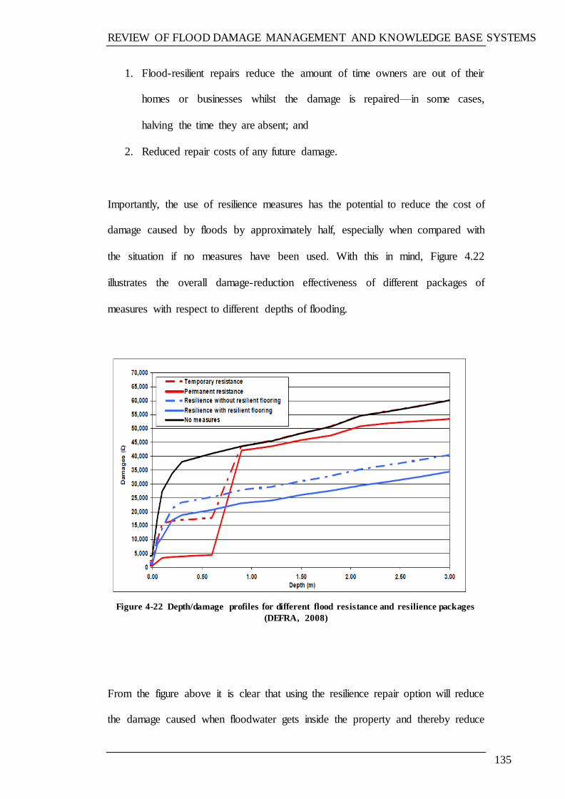
REVIEW OF FLOOD DAMAGE MANAGEMENT AND KNOWLEDGE BASE SYSTEMS
135
1. Flood-resilient repairs reduce the amount of time owners are out of their
homes or businesses whilst the damage is repaired—in some cases,
halving the time they are absent; and
2. Reduced repair costs of any future damage.
Importantly, the use of resilience measures has the potential to reduce the cost of
damage caused by floods by approximately half, especially when compared with
the situation if no measures have been used. With this in mind, Figure 4.22
illustrates the overall damage-reduction effectiveness of different packages of
measures with respect to different depths of flooding.
Figure 4-22 Depth/damage profiles for different flood resistance and resilience packages
(DEFRA, 2008)
From the figure above it is clear that using the resilience repair option will reduce
the damage caused when floodwater gets inside the property and thereby reduce
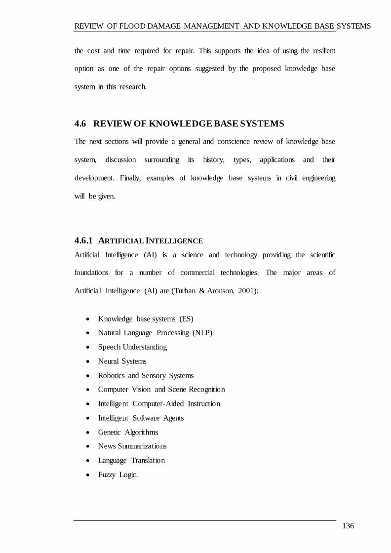
REVIEW OF FLOOD DAMAGE MANAGEMENT AND KNOWLEDGE BASE SYSTEMS
136
the cost and time required for repair. This supports the idea of using the resilient
option as one of the repair options suggested by the proposed knowledge base
system in this research.
4.6 REVIEW OF KNOWLEDGE BASE SYSTEMS
The next sections will provide a general and conscience review of knowledge base
system, discussion surrounding its history, types, applications and their
development. Finally, examples of knowledge base systems in civil engineering
will be given.
4.6.1 ARTIFICIAL INTELLIGENCE
Artificial Intelligence (AI) is a science and technology providing the scientific
foundations for a number of commercial technologies. The major areas of
Artificial Intelligence (AI) are (Turban & Aronson, 2001):
Knowledge base systems (ES)
Natural Language Processing (NLP)
Speech Understanding
Neural Systems
Robotics and Sensory Systems
Computer Vision and Scene Recognition
Intelligent Computer-Aided Instruction
Intelligent Software Agents
Genetic Algorithms
News Summarizations
Language Translation
Fuzzy Logic.

REVIEW OF FLOOD DAMAGE MANAGEMENT AND KNOWLEDGE BASE SYSTEMS
137
The term ‗Intelligent Systems‘ covers various applications of Artificial
Intelligence (AI) (Figure 4.23). Markedly, Knowledge base systems (ES) is
the sub-discipline of AI which is applied and utilised more commonly than
any other AI technology (Turban & Aronson, 2001).
Figure 4-23: Major areas of artificial intelligence (AI) (Turban & Aronson, 2001)
4.6.1.1 Expert system definitions (ES)
Knowledge base systems are the most popular applied Artificial Intelligence (AI)
technology. The terms ‗knowledge base systems‘, ‗knowledge-based systems‘,
and ‗knowledge-based knowledge base systems‘ are commonly applied
REVIEW OF FLOOD DAMAGE MANAGEMENT AND KNOWLEDGE BASE SYSTEMS
138
synonymously (Giarratano & Riley, 1998). With this in mind, Turban & Aronson
(2001) mention that the reference to ‗knowledge base system‘ derived from the
term ‗knowledge-based knowledge base system‘. In the beginning, knowledge
base systems only contained expert knowledge and, although the term knowledge-
based system (KBS) is more suitable, most people use knowledge base system
(ES) because it is shorter. With the aforementioned in mind, knowledge base
systems can therefore be defined as systems of knowledge bases (because they
work on the use of knowledge or facts that are used by human experts).
Importantly, there are numerous assigned to the concept of knowledge base
systems (ES). Some definitions taken from the literature and the internet are
provided below:
‘A computer system capable of giving advice in a particular knowledge domain,
by virtue of the fact that it contains knowledge provided by a human expert in this
domain.‘ (Source: http://www.mdx.ac.uk/www/ai/samples/ke/50-EXPE.HTM)
‗An expert system is a class of computer programs developed by researchers in
artificial intelligence during the 1970s and applied commercially throughout the
1980s. In essence, they are programs made up of a set of rules that analyse
information (usually supplied by the user of the system) about a specific class of
problems, as well as provide analysis of the problem(s), and, depending upon
their design, a recommended course of user action in order to implement
corrections.‘
(Source: Wikipedia, the free encyclopaedia-(http://en.wikipedia.org/wiki/
Expert_system)
REVIEW OF FLOOD DAMAGE MANAGEMENT AND KNOWLEDGE BASE SYSTEMS
139
‘Is a system that uses human knowledge captured in a computer to solve problems
that ordinarily require human expertise‘ (Turban & Aronson, 2001).
Adeli (1988) also cites three definitions of knowledge base systems, as follows:
‗An intelligent computer program that uses knowledge and inference
procedures to solve problems that is difficult enough to require significant
human expertise for their solution‘. (Feigenbaum, 1981).
‗Knowledge base system or ES is a computer program that reasons with
the knowledge of a specialist subject with a view to solving problems or
giving advice.‘ (Bian, Sha and Hong 1995).
‗An knowledge base system solves real-world, complex problems using a
complex model of expert human reasoning, reaching the same conclusions
that the human expert would reach if faced with a comparable problem‘.
(Weiss & Kulikowski, 1984).
4.6.1.2 History of knowledge base systems
Beginning in the mid-1960s, this new type of system was developed with the aim
of supporting management throughout the decision-making process. The first
system was designed (DENDRAL program) in 1965 in order to address the issue
of chemical composition of materials. This programme contained a great deal of
specialist chemical information, and the success of the program subsequently led
to the development and growth of knowledge base systems, as well as the
enhancement of companies specialising in the production of knowledge base
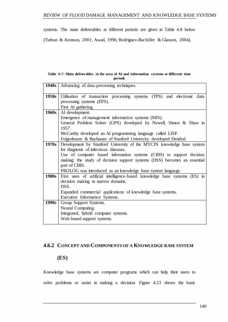
REVIEW OF FLOOD DAMAGE MANAGEMENT AND KNOWLEDGE BASE SYSTEMS
140
systems. The main deliverables at different periods are given in Table 4.8 below
(Turban & Aronson, 2001; Awad, 1996; Rodriguez-Bachiller & Glasson, 2004).
Table 4-7: Main deliverables in the area of AI and information systems at different time
periods
1940s Advancing of data-processing techniques.
1950s Utilisation of transaction processing systems (TPS) and electronic data processing systems (EPS).
First AI gathering.
1960s AI development. Emergence of management information systems (MIS). General Problem Solver (GPS) developed by Newell, Simon & Shaw in
1957. McCarthy developed an AI programming language called LISP.
Feigenbaum & Buchanan of Stanford University developed Dendral.
1970s Development by Stanford University of the MYCIN knowledge base system for diagnosis of infectious diseases. Use of computer based information systems (CBIS) to support decision
making; the study of decision support systems (DSS) becomes an essential part of CBIS.
PROLOG was introduced as an knowledge base system language.
1980s First uses of artificial intelligence-based knowledge base systems (ES) in decision making in narrow domains. DSS.
Expanded commercial applications of knowledge base systems. Executive Information Systems.
1990s Group Support Systems.
Neural Computing. Integrated, hybrid computer systems.
Web-based support systems.
4.6.2 CONCEPT AND COMPONENTS OF A KNOWLEDGE BASE SYSTEM
(ES)
Knowledge base systems are computer programs which can help their users to
solve problems or assist in making a decision. Figure 4.23 shows the basic
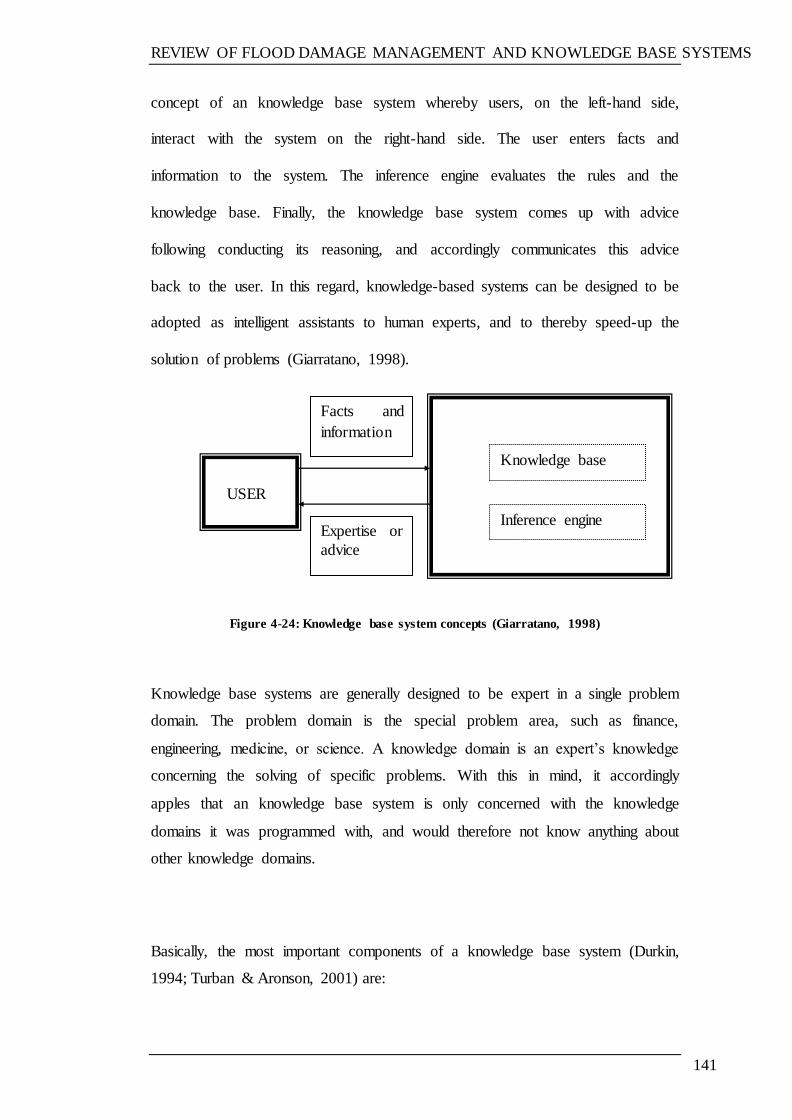
REVIEW OF FLOOD DAMAGE MANAGEMENT AND KNOWLEDGE BASE SYSTEMS
141
concept of an knowledge base system whereby users, on the left-hand side,
interact with the system on the right-hand side. The user enters facts and
information to the system. The inference engine evaluates the rules and the
knowledge base. Finally, the knowledge base system comes up with advice
following conducting its reasoning, and accordingly communicates this advice
back to the user. In this regard, knowledge-based systems can be designed to be
adopted as intelligent assistants to human experts, and to thereby speed-up the
solution of problems (Giarratano, 1998).
Figure 4-24: Knowledge base system concepts (Giarratano, 1998)
Knowledge base systems are generally designed to be expert in a single problem
domain. The problem domain is the special problem area, such as finance,
engineering, medicine, or science. A knowledge domain is an expert‘s knowledge
concerning the solving of specific problems. With this in mind, it accordingly
apples that an knowledge base system is only concerned with the knowledge
domains it was programmed with, and would therefore not know anything about
other knowledge domains.
Basically, the most important components of a knowledge base system (Durkin,
1994; Turban & Aronson, 2001) are:
USER
Knowledge base
Inference engine Expertise or
advice
Facts and
information
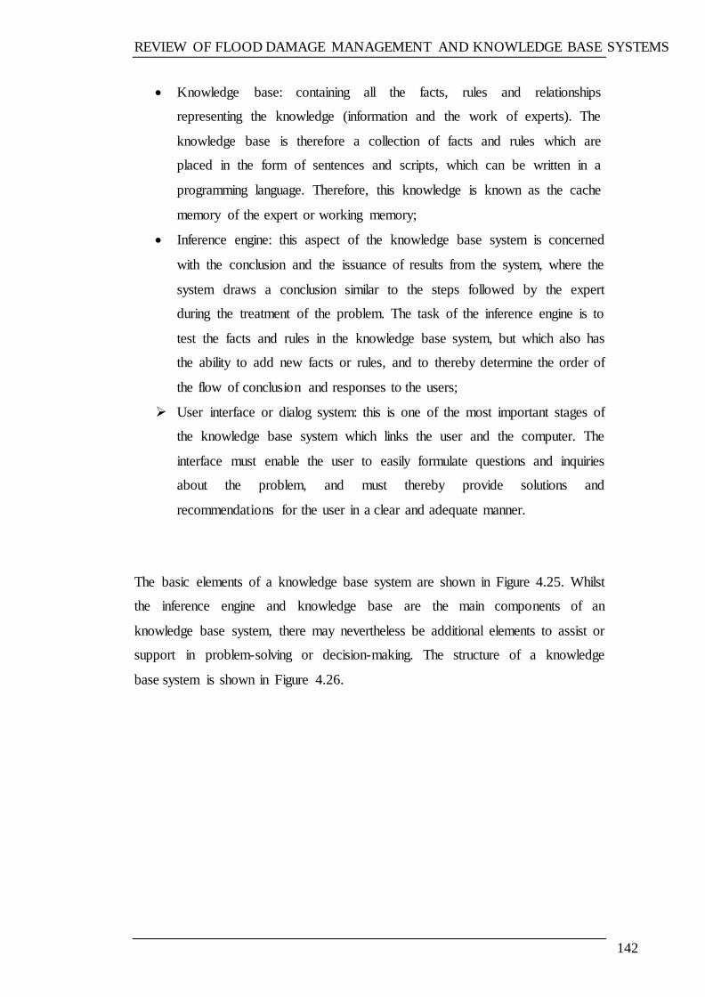
REVIEW OF FLOOD DAMAGE MANAGEMENT AND KNOWLEDGE BASE SYSTEMS
142
Knowledge base: containing all the facts, rules and relationships
representing the knowledge (information and the work of experts). The
knowledge base is therefore a collection of facts and rules which are
placed in the form of sentences and scripts, which can be written in a
programming language. Therefore, this knowledge is known as the cache
memory of the expert or working memory;
Inference engine: this aspect of the knowledge base system is concerned
with the conclusion and the issuance of results from the system, where the
system draws a conclusion similar to the steps followed by the expert
during the treatment of the problem. The task of the inference engine is to
test the facts and rules in the knowledge base system, but which also has
the ability to add new facts or rules, and to thereby determine the order of
the flow of conclusion and responses to the users;
User interface or dialog system: this is one of the most important stages of
the knowledge base system which links the user and the computer. The
interface must enable the user to easily formulate questions and inquiries
about the problem, and must thereby provide solutions and
recommendations for the user in a clear and adequate manner.
The basic elements of a knowledge base system are shown in Figure 4.25. Whilst
the inference engine and knowledge base are the main components of an
knowledge base system, there may nevertheless be additional elements to assist or
support in problem-solving or decision-making. The structure of a knowledge
base system is shown in Figure 4.26.
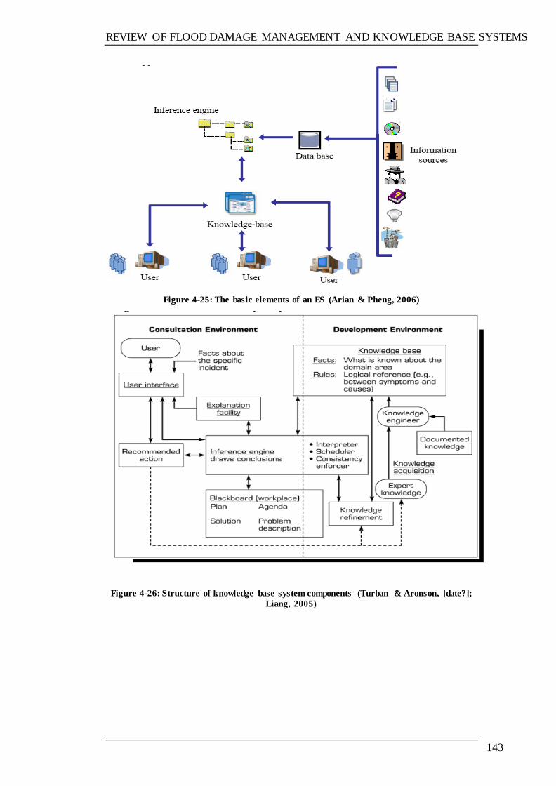
REVIEW OF FLOOD DAMAGE MANAGEMENT AND KNOWLEDGE BASE SYSTEMS
143
Figure 4-25: The basic elements of an ES (Arian & Pheng, 2006)
Figure 4-26: Structure of knowledge base system components (Turban & Aronson, [date?];
Liang, 2005)
REVIEW OF FLOOD DAMAGE MANAGEMENT AND KNOWLEDGE BASE SYSTEMS
144
4.6.3 TYPES OF KNOWLEDGE BASE SYSTEM
Knowledge base systems can range from a simple system which seeks to answer a
straightforward query, to a complex system providing a solution or advice relating
to a complicated problem, based on its related database. The main types of
knowledge base system are (Turban & Aronson, 2001):
1. Rule-based Systems: knowledge represented by a series of rules. The rule-
based approach uses an IF-THEN type rule or CONDITION-ACTION,
rules and it is the method currently used;
2. Custom-made Systems: meeting the specific needs of a user;
3. Frame-based Systems: knowledge represented through frames linked
together in a certain manner;
4. Hybrid Systems: several approaches are combined—commonly rules and
frames;
5. Off-the-shelf Systems: ready-made packages for general use;
6. Model-based Systems: models which simulate the structure and functions
of systems; and
7. Real-time Systems: strict limits set on system response times.
4.6.4 KNOWLEDGE BASE SYSTEM APPLICATIONS
One of several methods of knowledge base system classification is by the general
problems they address. The general categories of knowledge base system are
listed in Table 4.8.
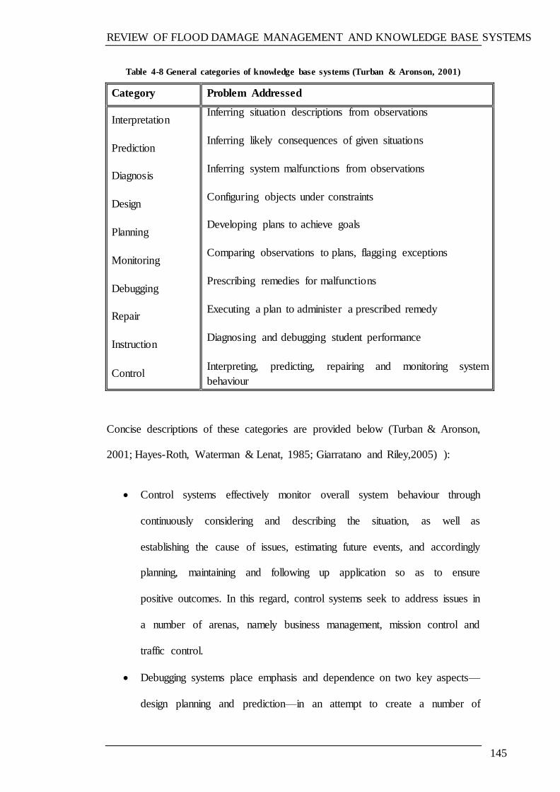
REVIEW OF FLOOD DAMAGE MANAGEMENT AND KNOWLEDGE BASE SYSTEMS
145
Table 4-8 General categories of knowledge base systems (Turban & Aronson, 2001)
Category Problem Addressed
Interpretation
Prediction
Diagnosis
Design
Planning
Monitoring
Debugging
Repair
Instruction
Control
Inferring situation descriptions from observations
Inferring likely consequences of given situations
Inferring system malfunctions from observations
Configuring objects under constraints
Developing plans to achieve goals
Comparing observations to plans, flagging exceptions
Prescribing remedies for malfunctions
Executing a plan to administer a prescribed remedy
Diagnosing and debugging student performance
Interpreting, predicting, repairing and monitoring system
behaviour
Concise descriptions of these categories are provided below (Turban & Aronson,
2001; Hayes-Roth, Waterman & Lenat, 1985; Giarratano and Riley,2005) ):
Control systems effectively monitor overall system behaviour through
continuously considering and describing the situation, as well as
establishing the cause of issues, estimating future events, and accordingly
planning, maintaining and following up application so as to ensure
positive outcomes. In this regard, control systems seek to address issues in
a number of arenas, namely business management, mission control and
traffic control.
Debugging systems place emphasis and dependence on two key aspects—
design planning and prediction—in an attempt to create a number of
REVIEW OF FLOOD DAMAGE MANAGEMENT AND KNOWLEDGE BASE SYSTEMS
146
recommendations or specifications for dealing with and subsequently
overcoming defined issues.
Design systems provide configurations for those items which fulfil the
restrictions posed by design issues, including budgeting, building design
and layout.
Diagnosis systems are those which create a link between noted
behavioural irregularities and the causes of such. This category comprises
diagnoses in the areas of electronic, mechanical, medical and software.
Instruction systems establish and overcome student knowledge problems,
and accordingly determine the most feasible solutions for overcoming
such weaknesses.
Interpretation systems seek to describe the noted information items
through attributing symbolic meanings to each. Importantly, this category
comprises image analysis, intelligent analysis, signal interpretation, speech
understanding and surveillance.
Monitoring systems conduct comparisons between system behaviours and
characteristics considered to be valuable in regard to plan results. In this
regard, a number of computer monitoring systems are in implementation,
including air traffic control, factor management and nuclear power plants.
Planning systems are concerned with planning-related issues, including
automatic programming. Notably, such systems also consider a number of
different areas of planning, including communications, military planning,
project management and routing.
Prediction systems apply parametric dynamic frameworks along with
parameter values assigned to the particular context. In this regard,

REVIEW OF FLOOD DAMAGE MANAGEMENT AND KNOWLEDGE BASE SYSTEMS
147
prediction systems may comprise crop predictions, demographic
predictions, military forecasting, traffic predictions and weather
forecasting.
Repair systems create and operate plans in an attempt to establish
solutions to various diagnostic problems.
4.6.5 KNOWLEDGE BASE SYSTEMS STRUCTURE AND DESIGN
The process of building an knowledge base system is known as knowledge
engineering. An knowledge base system development lifecycle model is
illustrated in Figure 4.26. Notably, there are six main stages in the developing of
an knowledge base system, which are listed below, as provided by Durkin (1994)
and Negnevitsky (2005):
Problem assessment;
Data and knowledge acquisition;
Development of a prototype system;
Development of a complete system;
Evaluation and revision of the system; and
Integration and maintenance of the system.
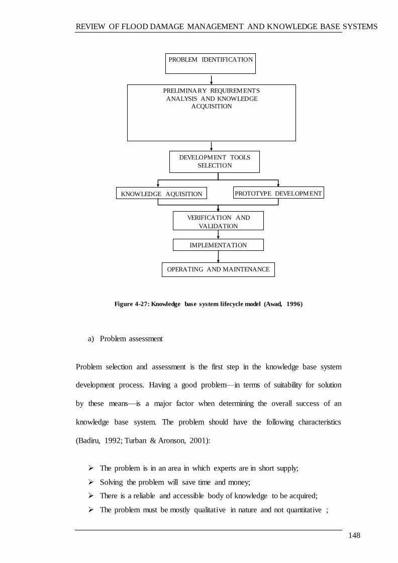
REVIEW OF FLOOD DAMAGE MANAGEMENT AND KNOWLEDGE BASE SYSTEMS
148
Figure 4-27: Knowledge base system lifecycle model (Awad, 1996)
a) Problem assessment
Problem selection and assessment is the first step in the knowledge base system
development process. Having a good problem—in terms of suitability for solution
by these means—is a major factor when determining the overall success of an
knowledge base system. The problem should have the following characteristics
(Badiru, 1992; Turban & Aronson, 2001):
The problem is in an area in which experts are in short supply;
Solving the problem will save time and money;
There is a reliable and accessible body of knowledge to be acquired;
The problem must be mostly qualitative in nature and not quantitative ;
PRELIMINARY REQUIREMENTS
ANALYSIS AND KNOWLEDGE
ACQUISITION
PROBLEM IDENTIFICATION
DEVELOPMENT TOOLS
SELECTION
KNOWLEDGE AQUISITION PROTOTYPE DEVELOPMENT
VERIFICATION AND
VALIDATION
IMPLEMENTATION
OPERATING AND MAINTENANCE
REVIEW OF FLOOD DAMAGE MANAGEMENT AND KNOWLEDGE BASE SYSTEMS
149
The required knowledge must be in a narrow area; and
The user interface must be friendly for learner users.
Moreover, it is recognised that problem assessment should include a number of
steps (Negnevitsky, 2005):
Determining the problem‘s characteristics
Determining the resources required for system building
Specifying the project‘s objectives.
b) Data and knowledge acquisition
This task is the most difficult challenge in the development of an knowledge base
system (Durkin, 1994). At this stage, the knowledge engineer gathers data from
experts, textbooks, technical manuals, and research papers, etc. This acquired
knowledge is subsequently converted to an electronic format for use by the
computer program in question.
Kendal and Creen (2007) mention three types of knowledge which the knowledge
engineer commonly deals with, namely:
Declarative knowledge, which informs us of relevant facts;
Meta-Knowledge: is knowledge about knowledge, which shows how the
expert use the knowledge to solve specific problem; and
Procedural knowledge, which provides other actions based on the use of
facts in an attempt to gain knowledge.
According to Milton (2007) the utilisation of acquired knowledge falls into three
categories:
REVIEW OF FLOOD DAMAGE MANAGEMENT AND KNOWLEDGE BASE SYSTEMS
150
Information can be shared amongst individuals through special websites
known as knowledge web
Such information can be shared amongst computer systems in cases where
data is coded according to ‗ontology‘, which is a special format permitting
services or systems to utilise data as and when required
Knowledge can be utilised as one aspect of knowledge base system
development in the form of a knowledge document, which is utilised by
software developers during the development process. Notably, this could
be an knowledge base system, a knowledge-based engineer system, or a
knowledge-based system.
During the overall data-gathering process, the knowledge engineer is required to
carry out four key activities (Negnevitsky, 2005):
1. The engineer needs to ensure comprehension and understanding of the
key aim and objectives of the suggested knowledge base system;
2. The engineer is then required to establish working data concerning the
problem domain and ensure understanding of terminology, which can
be achieved through research.
3. Further in-depth knowledge should be ascertained, such as through the
conduction of interviews with relevant professionals.
4. The gathered data should be analysed and evaluated in order to create a
‗document knowledge base‘ or a group of documents for the
communication of such data to the computer program.
Castellanos et al., (2011) described the available knowledge for the knowledge
base system as below:
REVIEW OF FLOOD DAMAGE MANAGEMENT AND KNOWLEDGE BASE SYSTEMS
151
1. Direct Approach: The knowledge acquired directly from the human expert,
through interviews or questionnaire, obtaining an explanation of the
knowledge that the expert used to solve a particular problem.
2. As a result verbal data are obtained and then interpreted by the
programmer or knowledge base system designer.
3. Observational Approach: In this case, the knowledge engineer reflect the
experience of the expert in him/her job and asks to explain of process step
by step, while carrying out his/her job.
4. Indirect Approach: The the programmer or designer of the system experts
applies a method through it is expected that the expert will reveal his
information.
5. Machine Learning Approach: In this case, software with learning
algorithms is used to guess the knowledge from domain examples
provided by the experts.
6. Document Processing: In this case the knowledge is acquired through
technical reports, books, journals, articles, etc.
c) Development of a prototype system
A prototype system is defined as a small version of the final system, which has
limited ability (Durkin, 1994). The purposes of a prototype system are (Durkin,
1994):
To validate the knowledge base system approach;
REVIEW OF FLOOD DAMAGE MANAGEMENT AND KNOWLEDGE BASE SYSTEMS
152
To confirm that the choice of tools selected for building the system and the
techniques for representing the acquired data and knowledge are all
adequate in relation to the task; and
To provide a vehicle for knowledge acquisition.
The development of a prototype system includes, which used in developing of the
proposed system in this research:
Selecting a tool for building an intelligent system;
Transforming data and representing knowledge;
Design and implementation; and
Testing with test cases.
d) Development of a complete system
This stage includes (Negnevitsky, 2005; Turban & Aronson, 2001):
Preparing a detailed design for a full-scale system;
Collecting additional data and knowledge that might be needed;
Developing the user interface; and
Implementing the complete system.
e) Evaluation and revision of the system
At this stage, the system is revised and further evaluated against the performance
criteria. Owing to the fact that intelligent systems are not like conventional
computer programs in the sense that they are developed to solve problems which
do not have exact solutions (right or wrong), the system should then be evaluated
REVIEW OF FLOOD DAMAGE MANAGEMENT AND KNOWLEDGE BASE SYSTEMS
153
or validated in order to meet the user‘s requirements and to thereby ensure that it
does what it was designed to do. A comparison between the development
lifecycles of a conventional information system and an knowledge base system are
shown in Figure, as provided by Awad (1996). The evaluation of the system is
normally accomplished through demonstrating the results of test cases
(Negnevitsky, 2005). The proposed system in this research was evaluated and
validated for its performance, applicability, and general performance.
4.6.5.1 Building tools for knowledge base systems
There are a number of tools for knowledge base system development, ranging
from high-level programming languages through to ready-to-use applications
packages (Awad, 1996). Four levels are used to classify building tools, as detailed
below and highlighted in Figure 4.28 (Awad, 1996):
Programming languages: these may be more traditional and long-standing,
such as LISP, which is the oldest programming language, or modern and
relatively recent, such as in the cases of C++ and VB.
Shells: these are reasoning systems provided without information. In this
regard, it can be stated that knowledge base system shells comprise a
number of key elements contained within an knowledge base system with
the exception of knowledge content (Turban & Aronson, 2001). In this
regard, it is further emphasised by Awad (1996) that a questionnaire
concerning modern knowledge base system applications highlight that the
REVIEW OF FLOOD DAMAGE MANAGEMENT AND KNOWLEDGE BASE SYSTEMS
154
majority were created with the use of shells as opposed to alternative
languages.
Special knowledge base system packages: these are programs provided on
a ready-to-use basis, which provide users within the arena with advice and
important insight into how to deal with various issues arising in the area.
Support tools and aids: various tools are available for the creation of a user
interface, the editing of programs, the gathering of data, and the validation
and verification of programs.
It is noted by Adeli (1994) that an a programming environment or expert shell
considered appropriate for engineering applications must have the capacity to deal
with both numerical and scientific calculations within the system. Moreover, he
further states what needs to be taken into account when choosing ES shells in
terms of engineering applications.
1. Availability of mathematical routines
2. Cost
3. Maximum number of rules
4. Portability
5. Program aids
6. Response time
7. The ability to interface with other programs written in the language of the
shell or another language
8. The type of application
9. Type of control strategy and inference mechanism
10. Type of machine and operating system

REVIEW OF FLOOD DAMAGE MANAGEMENT AND KNOWLEDGE BASE SYSTEMS
155
11. User support.
Figure 4-28: Classification of building tools (Awad, 1996)
For the development of the prototype system in this research, programming
languages were used to develop the system (Visual Basic) were the system
developed from scratch. The programming language was selected because of the
author‘s previous knowledge of this language and its low cost compared with
knowledge based system shells.
REVIEW OF FLOOD DAMAGE MANAGEMENT AND KNOWLEDGE BASE SYSTEMS
156
4.6.5.2 Benefits of knowledge base systems
Turban, Aronson and Liang (2005); Awad (1996) and Turban et al, (2008) list and
discuss the benefits associated with knowledge base systems, as those given
below:
1. Increased output and productivity
2. Decreased decision making time
3. Increased processes and product quality
4. Reduced downtime
5. Flexible and easy to modify compared with traditional programs
6. Elimination of expensive equipment
7. Make equipment operation easier
8. Integration of several experts' opinions
9. Deal with incomplete or uncertain information
10. Provide training by providing knowledge and information
11. Improved problem-solving and decision making
12. Improved decision making processes
13. Improved decision quality
14. Ability to solve complex problems.
4.7 APPLICATIONS OF KNOWLEDGE BASE SYSTEMS IN
CIVIL ENGINEERING
Knowledge base systems have been applied as assessment tools for the purposes
of design, maintenance and management in all fields of civil engineering. Some
such examples of developed knowledge base systems are provided below:
REVIEW OF FLOOD DAMAGE MANAGEMENT AND KNOWLEDGE BASE SYSTEMS
157
A. Applications in concrete technology
COMIX: rule- and frame-based knowledge base systems which provide
advice on the design of concrete mixes. The system has been designed
for use by concrete technologists, design engineers, and consultants
(Kaetzel & Clifton, 1993).
DURCON: knowledge base systems which provide suggestions
concerning the choice of concrete material for the following durability
areas: corrosion freeze-thaw, sulphate attack, alkali-aggregate reaction
(Kaetzel & Clifton, 1993).
HPCMIX: prototype knowledge base systems which provide proportions
for trial mixing of High Performance Concrete (HPC). The system is
based on knowledge from textual and human experts. HPCMIX is
capable of selecting the mixing proportions of water, cement,
supplementary cementation materials and aggregate, considering the air
content and moisture condition of the aggregate (Zain, Islam & Basri,
2005).
B. Structural assessment applications
A hybrid reasoning system: a knowledge-based system developed for
damage assessment of structures. The system combines use of a model
of the structure with a knowledge-based reasoning scheme to evaluate
whether or not damage is present, as well as its overall severity and
location (Mujica, Rodellar & Kolakowski, 2005).
C. Dam engineering applications
CASTOR: a dam safety assessment system integrated with a knowledge-
based system (SISAS). This system has been developed with the
objective to assess engineers responsible for dam safety assessment
(Farinha, Portela, Domingues & Sousa, 2005).
REVIEW OF FLOOD DAMAGE MANAGEMENT AND KNOWLEDGE BASE SYSTEMS
158
D. Railway tunnelling applications
MATUF system: a knowledge-based system designed in order to assist
in the making of recommendations for diagnosis and the repair of
tunnels. The system integrates various different types of knowledge
obtained from experts in the field of underground work. Notably, it is
designed to represent the information obtained, to carry out a brief
assessment of the safety conditions of the work, and to thereby classify
the tunnel with reference to its safety level, accordingly making
recommendations for its repair (Farinha, Portela, Domingues & Sousa,
2005).
E. Structure design applications
A knowledge-based system for liquid retaining structures. This is a
prototype knowledge-based system developed for the design of liquid
retaining structures based on the blackboard architecture. The system is
tailored to provide advice regarding preliminary design, loading
specifications, and optimised configuration selection for this type of
structure (Chau & Albermani, 2005).
BREXS: Bridge Rail Knowledge base system is an advisory system
developed to assist novice engineers with railway bridge design. The
goals of this system are to incorporate a railway bridge knowledge base,
a railway bridge database and analytical computer codes to aid in
decision-making (Tommelein, 1997).
CUFAD+: Compression and Uplift Foundation Analysis and Design is a
knowledge-based expert advice system built for use in designing
foundations for electric power transmission line structures. The goal of
REVIEW OF FLOOD DAMAGE MANAGEMENT AND KNOWLEDGE BASE SYSTEMS
159
this system is to provide engineers with the capacity to make better
designs (Tommelein, 1997).
F. Environmental engineering
LDEM-DSS: A decision support system for landfill design, evaluation,
and monitoring. LDEM contains a number of decision support modules
related to the various design and monitoring operations of sanitary landfill
(Lukasheh et al., 2001).
SLEUTH: A decision support system in landfill design and waste
management evaluation including transport and hydrology. SLEUTH was
developed for the design and remediation of shallow landfill burial
systems (Lukasheh et al., 2001).
G. Construction management (maintenance and repair)
(ESMHS) Knowledge base system for maintenance of Major Hydraulic
Structures. This system is applied for the diagnosis of different types and
classes of problem which may occur in various different elements of
masonry barrages (de Brito, Branco & Ibañez, 1994).
A Knowledge-based Advisory System for the Diagnosis and Repair of
Subsidence Damage: This system is provided to improve the management
of subsidence cases by providing engineers with intelligent advice at all
stages of the management process (Anumba et al., 1995).
Knowledge base system for Maintenance and Repair of Masonry Barrages:
This knowledge base system developed for diagnosis of various types and
categories of problems that may occur in the various elements of Masonry
REVIEW OF FLOOD DAMAGE MANAGEMENT AND KNOWLEDGE BASE SYSTEMS
160
Barrages. The system helps to recognize possible causes, and propose the
suitable method of remediation.
Knowledge base system for Airport Pavement Maintenance and
Rehabilitation: This knowledge base system is developed to help in
identifying the problems related to airport pavements and structures,
diagnosing the cause of deterioration, recommending the repair actions,
and estimate the cost of repair (Ismail, Ismail & Atiq, 2009).
4.8 SUMMARY
There are different causes of flood such as sea, rivers and streams, blocked or
overloaded drainage systems and sewers, and ground water. One of the most
common causes of flooding is excessive rain. Some 2.1 million homes in the
whole of the UK are in areas which are considered to be at risk from river and sea
flooding. Flood damage can range from minor to more severe cases, where
extensive damage occurs. Damage caused to a property is dependent on the
characteristics of the flood, as well as of the building itself. There are a number of
issues which can arise during the repair stage which emphasise clearly that there is
a need to establish repair standards. Considering using resilient repair options will
reduce repair costs of any future damage.
Knowledge base systems have been applied as assessment tools for the purposes
of design, maintenance and management in all fields of civil engineering and
could be helpful in the field of flooded building damage management.

REVIEW OF FLOOD DAMAGE MANAGEMENT AND KNOWLEDGE BASE SYSTEMS
161
The next chapter will discuss the Knowledge acquisition for prototype development.

KNOWLEDGE ACQUISITION FOR PROTOTYPE DEVLOPMENT
162
CHAPTER 5 KNOWLEDGE ACQUISITION FOR
PROTOTYPE DEVLOPMENT
5.1 INTRODUCTION
The chapter present the results of the survey and the knowledge elicited in the
knowledge acquisition stage from various different documents reviewed,
summarises the remediation options available for each building elements, and
finally demonstrates the remediation options used by the prototype system.
5.2 METHODOLOGY USED
Data generation methods are a means by which empirical (field) data or evidence
is produced. In this regard, data can be either quantitative or qualitative:
quantitative data is a numeric data, whereas qualitative data is all other types of
data.
According to Oates (2006), there are four different data-generation methods, as
detailed below:
1. Interviews: a particular kind of conservation between people. One-to-one
or group interview are possible;
2. Observation: watching what people actually do, rather than what they
report they do.
3. Questionnaire: a predefined set of questions assembled in a pre-determined
order, which provides the research with data to be analysed or
interoperated;
KNOWLEDGE ACQUISITION FOR PROTOTYPE DEVLOPMENT
163
4. Documents: documents which already exist prior to the research, such as
academic literature, previous research, visual resource of data, and
organisation publications. Moreover, it is often useful to study relevant
documentation either as the main basis for a project or as complement to
the other methods of data collection (Cornford & Smithson, 2006; et al.,
2011).
Following the topic having been defined and the literature identified to be
reviewed, some issues related to the topic were also identified, workshops related
to the topic were identified in an attempt to gain updated knowledge as well as the
chance to meet experts and professionals in the arena. A number of workshops
were attended during the research time period. The unstructured interview
technique was used to collect preliminary information at the beginning of the
research, and to thereby gain updated information during the research timescale.
Moreover, an initial interview with experts were conducted in order to determine
what knowledge is to be acquired, the purpose of the knowledge, and to gain some
understanding of key terminology.
The information-gathering was carried out mainly through the use of
questionnaire surveys, technical publications and manuals, as well as attendance
at, and contributions to, flood management workshops where there has been the
opportunity to meet experts in the field in order to gain knowledge or update
existing knowledge. This is because of the nature of the information that needed
to be collected, especially related to the maintenance of buildings, where it was
difficult to elicit responses through the questionnaires alone. This applies to all
KNOWLEDGE ACQUISITION FOR PROTOTYPE DEVLOPMENT
164
cases of flooding damage repair: for example, in most cases where the flood depth
has not been deep, it was found that the responses concentrated on these cases
alone, therefore requiring the use of other sources, such as documents (a list of
documents are given in Table 2.5). During this phase, there was the need to rely
on such sources so that they would complement each other and meet shortfalls
which might occur as a result of reliance on one source.
5.2.1 THE QUESTIONNAIRE SURVEYS
Two questionnaire surveys were conducted: one on vulnerability assessment, and
the second on flood repair options.
5.2.1.1 Vulnerability assessment questionnaire
The survey was conducted with the aim of investigating factors that contribute to
the vulnerability of residential buildings to flood damage, and to thereby identify
their relative importance in contributing to the vulnerability of buildings to
damage from flooding. Moreover, there was also the need to identify any other
factors which might not have been apparent from the literature review, but which
were suggested based on the experiences elicited by the responses.
The questionnaire was designed in four parts: a covering letter, basic information
concerning the participant, the body of the questionnaire, and finally, space for
additional comments. A copy of the questionnaire is shown in Appendix A.
KNOWLEDGE ACQUISITION FOR PROTOTYPE DEVLOPMENT
165
Rating questions were used to investigate those factors affecting buildings‘
vulnerability to flood damage. Extra space was given in case the participants
wanted to add additional factors or make any further comments.
The questionnaire was sent to a number of contractors, researchers and experts in
the field of flood damage management, either by mail with an addressed and
stamped, return envelope, emailed, or otherwise handed out in person during the
workshops attended. The postal and email addresses of the contractors were
obtained by contacting various organisations, such as the Royal Institution of
Chartered Surveyors (RICS), the Association of British Insurers (ABI) and the
Environment Agency (EA), or were otherwise collected in person through
workshops. 50 questionnaires were sent and distributed to different participants.
Results
The following sections present the results of the survey of factors contributing to
the vulnerability of residential buildings to flood damage.
Response
14 questionnaires were received out of a total of 50 questionnaires distributed.
The response rate was 28%, which is acceptable considering that a 20–30%
response rate to postal questionnaire surveys is typical in the construction industry
(Akintoye et al., 2000).
Factors rating
All 14 participants ranked the factors given as being either important or very
important, with the exception of one participant, who ranked some factors as not
important. Only one extra factor was added by a participant, namely the existence
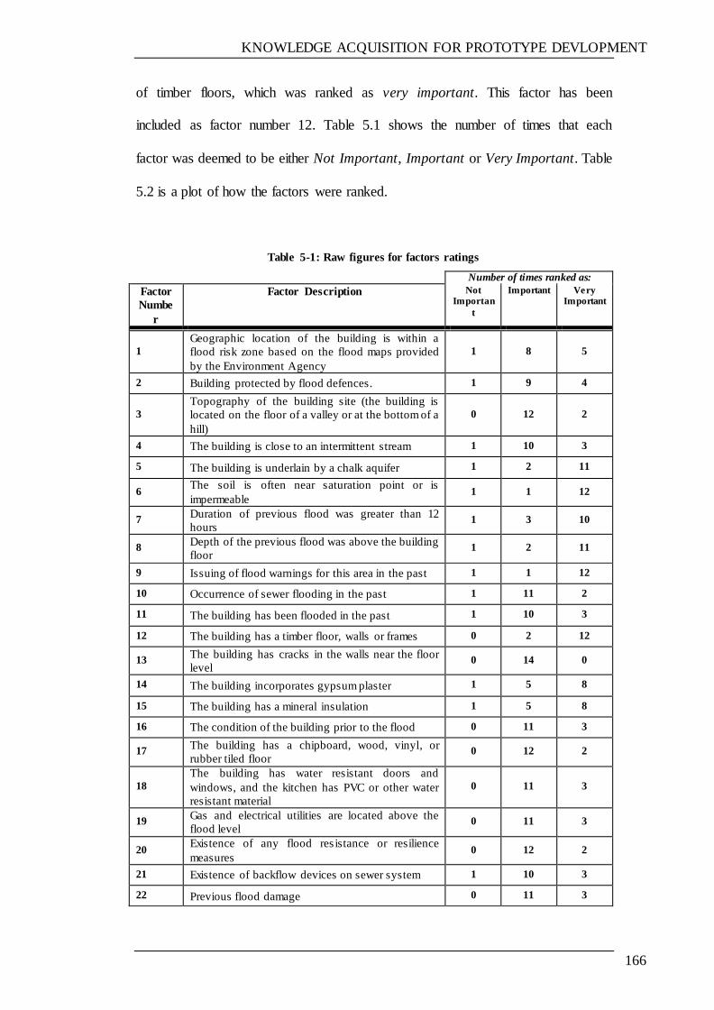
KNOWLEDGE ACQUISITION FOR PROTOTYPE DEVLOPMENT
166
of timber floors, which was ranked as very important. This factor has been
included as factor number 12. Table 5.1 shows the number of times that each
factor was deemed to be either Not Important, Important or Very Important. Table
5.2 is a plot of how the factors were ranked.
Table 5-1: Raw figures for factors ratings
Number of times ranked as:
Factor
Numbe
r
Factor Description
Not Importan
t
Important Very Important
1
Geographic location of the building is within a
flood risk zone based on the flood maps provided
by the Environment Agency
1 8 5
2 Building protected by flood defences. 1 9 4
3
Topography of the building site (the building is
located on the floor of a valley or at the bottom of a
hill)
0 12 2
4 The building is close to an intermittent stream 1 10 3
5 The building is underlain by a chalk aquifer 1 2 11
6 The soil is often near saturation point or is
impermeable 1 1 12
7 Duration of previous flood was greater than 12
hours 1 3 10
8 Depth of the previous flood was above the building
floor 1 2 11
9 Issuing of flood warnings for this area in the past 1 1 12
10 Occurrence of sewer flooding in the past 1 11 2
11 The building has been flooded in the past 1 10 3
12 The building has a timber floor, walls or frames 0 2 12
13 The building has cracks in the walls near the floor
level 0 14 0
14 The building incorporates gypsum plaster 1 5 8
15 The building has a mineral insulation 1 5 8
16 The condition of the building prior to the flood 0 11 3
17 The building has a chipboard, wood, vinyl, or
rubber tiled floor 0 12 2
18
The building has water resistant doors and
windows, and the kitchen has PVC or other water
resistant material
0 11 3
19 Gas and electrical utilities are located above the
flood level 0 11 3
20 Existence of any flood res istance or resilience
measures 0 12 2
21 Existence of backflow devices on sewer system 1 10 3
22 Previous flood damage 0 11 3

KNOWLEDGE ACQUISITION FOR PROTOTYPE DEVLOPMENT
167
Table 5-2: Plot of Factors ratings
Importantly, these results have been used as the basis for calculating the degree of
vulnerability, as discussed in Section 3.3.2.2.
5.2.1.2 Flood repair options questionnaire
The survey was conducted with the objective to investigate and identify options
and alternatives in existent, and is followed in the maintenance of buildings hit by
flooding, and also in relation to certain flood properties, such as flood depth,
KNOWLEDGE ACQUISITION FOR PROTOTYPE DEVLOPMENT
168
speed and duration. The survey addressed several issues, including damaged
building elements and the time taken to reinstate flooded buildings.
The questionnaire was designed in five parts: the covering letter, basic
information and flood characteristics, building characteristics and damage,
damaged components and remediation options, and finally space for additional
comments. Moreover, partially open-ended questions (multiple choices between
various options) were used in the survey on the repair of flood damaged buildings
so as to provide participants with the opportunity to add any other remediation
options they considered to be important. In addition, extra space was given for the
participants in case they wanted to add any comments. A copy of the survey is
shown in Appendix B.
The questionnaire was revised more than once, and several modifications were
made, with some questions being rephrased for clarity and the survey being
shortened from thirteen pages to eight pages. Accordingly, the questionnaire was
then sent to a number of contractors and experts in the field of flood damage
management, either by mail with an addressed and stamped, return envelope,
emailed, or otherwise handed out in person during the workshops that were
attended. The postal and email addresses of the contractors were obtained by
contacting various organisations such as THE Royal Institution of Chartered
Surveyors (RICS), THE Association of British Insurers (ABI) AND THE
Environment Agency (EA), or were collected in person during the workshops. 100
questionnaires were sent and distributed to different participants.
KNOWLEDGE ACQUISITION FOR PROTOTYPE DEVLOPMENT
169
Results
The following sections present the results of the survey into the options available
for repairing flood damaged buildings. Example of questionnaire survey reply is
given in Appendix B.
Response
16 questionnaires were returned out of 100 questionnaires that were delivered, but
only 12 were usable. The response rate was 12%, which is low considering that a
20–30% response rate for postal questionnaire surveys is typical in the
construction industry (Akintoye et al., 2000).
Moreover, owing to the diversity and the large amount of information needed to
be obtained from the questionnaire, as well as the overall lack of response, the
information that was gathered was not sufficient to cover all scenarios of flood
damage. For example, all the responses focused on cases where the flood depth
was very shallow, and so there was no possibility of obtaining information on
damage to walls, for example. Furthermore, most of the responses did not address
the use of resilience options as an alternative for the maintenance of flooded
buildings. Because of these reasons and the points mentioned in sections 4.5.2.1
and 4.5.2.2 in relation to those issues concerning flooded building maintenance
and management, it was deemed necessary to use publications and information
obtained through participation and attendance at relevant workshops in order to
complete the gathering of the information which was required for developing
strategies for the maintenance of buildings, and to thereby validate the
information obtained from the survey. Another reason was the need to consider
other alternatives, such as resilience repair. The use of documents will be clarified
KNOWLEDGE ACQUISITION FOR PROTOTYPE DEVLOPMENT
170
extensively in the following paragraphs. The reply from this survey questionnaire
is covered only some flood damage scenarios and used were useful.
5.2.2 REVIEW OF TECHNICAL PUBLICATIONS AND MANUALS
A number of documents have been used for this research (refer to Table 2.5).
Some of these documents are based on surveys investigating the selection of
different repair options, whilst others investigate the damage caused by water to
different building elements, based on laboratory tests and simulations of different
flood scenarios. Furthermore, there are a number of documents which offer repair
strategies, including resilience options (such as BRE, 2006). Documents including
PAS 64 (2005) offer repair standards and specifications. With this in mind, the
following sections set out the repair options for different elements of residential
buildings (ordinary or resilience) as elicited from these documents. This
information is then used in the knowledge base of the developed prototype.
5.2.2.1 Flood damaged building elements
The building elements that are subjected to flood damage will include:
Flood damaged foundations:
1- Ground erosion surrounding foundations;
2- Foundation subsidence and settlement;
3- Loosening of mortar;
4- Foundation cracks or partial damage.
Flood damaged floors:
1- Vinyl floor tiles submerged by floodwater;
2- Vinyl sheet floors submerged by floodwater;
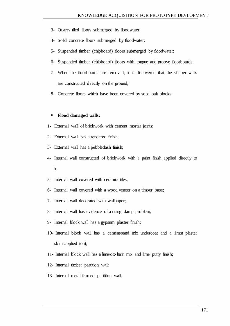
KNOWLEDGE ACQUISITION FOR PROTOTYPE DEVLOPMENT
171
3- Quarry tiled floors submerged by floodwater;
4- Solid concrete floors submerged by floodwater;
5- Suspended timber (chipboard) floors submerged by floodwater;
6- Suspended timber (chipboard) floors with tongue and groove floorboards;
7- When the floorboards are removed, it is discovered that the sleeper walls
are constructed directly on the ground;
8- Concrete floors which have been covered by solid oak blocks.
Flood damaged walls:
1- External wall of brickwork with cement mortar joints;
2- External wall has a rendered finish;
3- External wall has a pebbledash finish;
4- Internal wall constructed of brickwork with a paint finish applied directly to
it;
5- Internal wall covered with ceramic tiles;
6- Internal wall covered with a wood veneer on a timber base;
7- Internal wall decorated with wallpaper;
8- Internal wall has evidence of a rising damp problem;
9- Internal block wall has a gypsum plaster finish;
10- Internal block wall has a cement/sand mix undercoat and a 1mm plaster
skim applied to it;
11- Internal block wall has a lime/ox-hair mix and lime putty finish;
12- Internal timber partition wall;
13- Internal metal-framed partition wall.
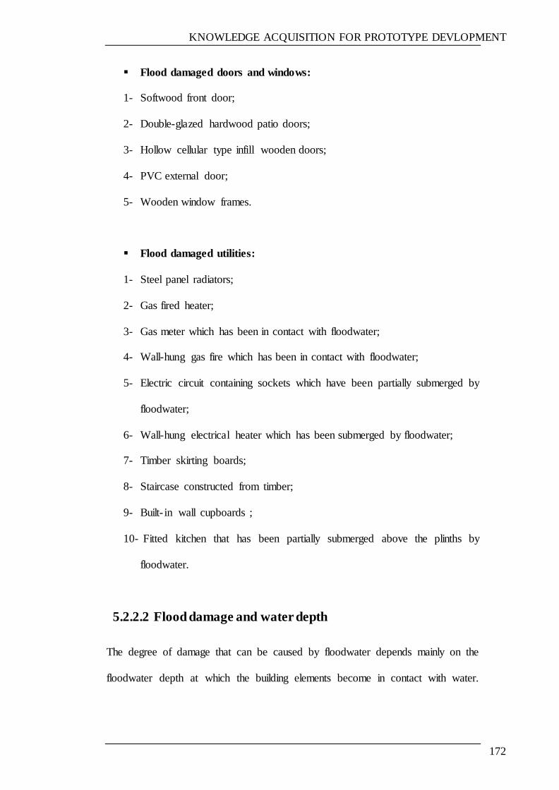
KNOWLEDGE ACQUISITION FOR PROTOTYPE DEVLOPMENT
172
Flood damaged doors and windows:
1- Softwood front door;
2- Double-glazed hardwood patio doors;
3- Hollow cellular type infill wooden doors;
4- PVC external door;
5- Wooden window frames.
Flood damaged utilities:
1- Steel panel radiators;
2- Gas fired heater;
3- Gas meter which has been in contact with floodwater;
4- Wall-hung gas fire which has been in contact with floodwater;
5- Electric circuit containing sockets which have been partially submerged by
floodwater;
6- Wall-hung electrical heater which has been submerged by floodwater;
7- Timber skirting boards;
8- Staircase constructed from timber;
9- Built- in wall cupboards ;
10- Fitted kitchen that has been partially submerged above the plinths by
floodwater.
5.2.2.2 Flood damage and water depth
The degree of damage that can be caused by floodwater depends mainly on the
floodwater depth at which the building elements become in contact with water.
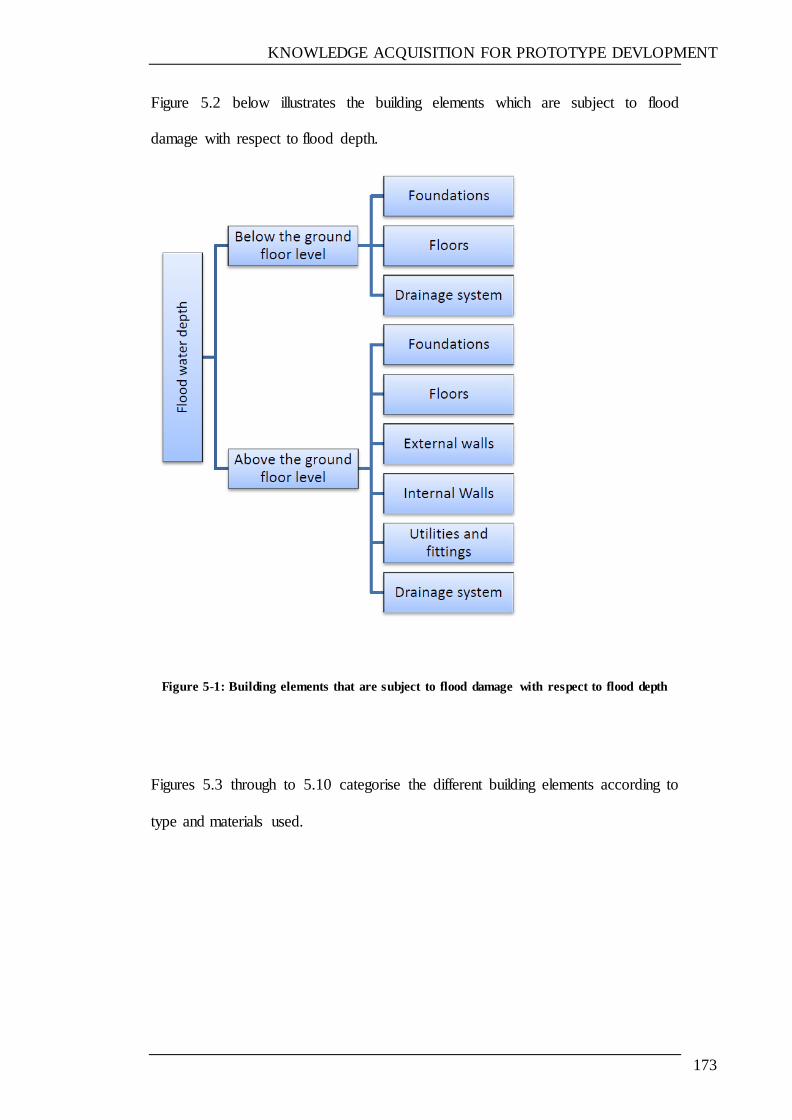
KNOWLEDGE ACQUISITION FOR PROTOTYPE DEVLOPMENT
173
Figure 5.2 below illustrates the building elements which are subject to flood
damage with respect to flood depth.
Figure 5-1: Building elements that are subject to flood damage with respect to flood depth
Figures 5.3 through to 5.10 categorise the different building elements according to
type and materials used.

KNOWLEDGE ACQUISITION FOR PROTOTYPE DEVLOPMENT
174
Figure 5-2: Categorised building elements (external walls)
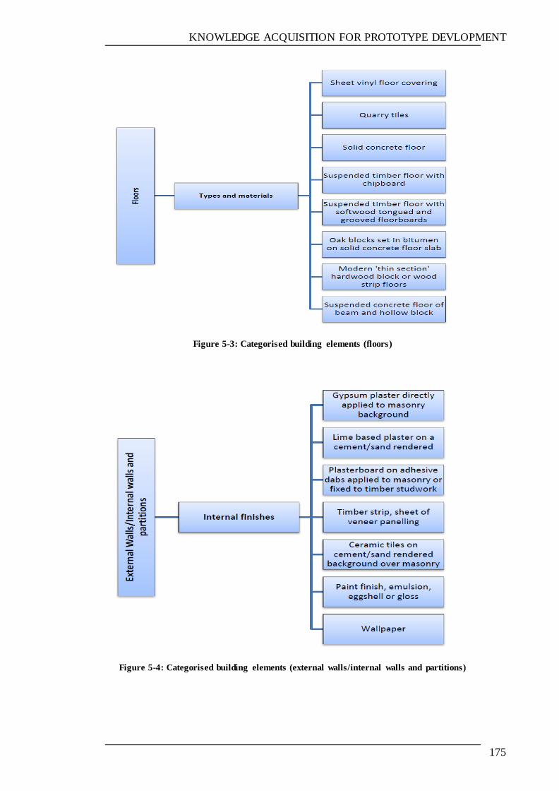
KNOWLEDGE ACQUISITION FOR PROTOTYPE DEVLOPMENT
175
Figure 5-3: Categorised building elements (floors)
Figure 5-4: Categorised building elements (external walls/internal walls and partitions)
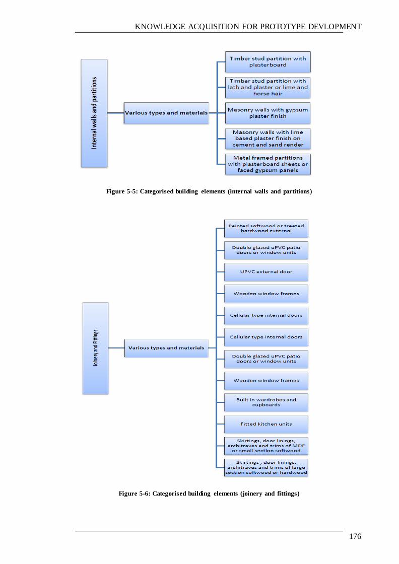
KNOWLEDGE ACQUISITION FOR PROTOTYPE DEVLOPMENT
176
Figure 5-5: Categorised building elements (internal walls and partitions)
Figure 5-6: Categorised building elements (joinery and fittings)

KNOWLEDGE ACQUISITION FOR PROTOTYPE DEVLOPMENT
177
Figure 5-7: Categorised building elements (services)
Figure 5-8: Categorised building elements (sanitary ware)
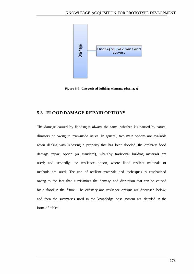
KNOWLEDGE ACQUISITION FOR PROTOTYPE DEVLOPMENT
178
Figure 5-9: Categorised building elements (drainage)
5.3 FLOOD DAMAGE REPAIR OPTIONS
The damage caused by flooding is always the same, whether it‘s caused by natural
disasters or owing to man-made issues. In general, two main options are available
when dealing with repairing a property that has been flooded: the ordinary flood
damage repair option (or standard), whereby traditional building materials are
used; and secondly, the resilience option, where flood resilient materials or
methods are used. The use of resilient materials and techniques is emphasised
owing to the fact that it minimises the damage and disruption that can be caused
by a flood in the future. The ordinary and resilience options are discussed below,
and then the summaries used in the knowledge base system are detailed in the
form of tables.
KNOWLEDGE ACQUISITION FOR PROTOTYPE DEVLOPMENT
179
5.3.1 FLOOD DAMAGE REPAIR OPTIONS
Some examples of repair strategies provided by the publications listed in Chapter
2 are shown in the subsequent tables. Proverbs & Soetanto (2004) present the
current benchmark strategies for reinstatement of a range of different flood
damage conditions which are common in domestic properties, as based on various
different flood damage scenarios. These benchmark repair strategies are based on
the literature review and various consultations with damage management experts,
insurers and loss adjusters, as well as questions to insurers and loss adjuster.
These strategies are summarised in tables 5.2 through to 5.5 below.
Soetanto, Proverbs, Lamond & Samwinga (2008) illustrate the ideal and resilient
repair strategies of different building components as shown in tables, as given
below.

KNOWLEDGE ACQUISITION FOR PROTOTYPE DEVLOPMENT
180
Table 5-3: Ideal and resilient repair strategies for flooded damaged floors (adapted from Soetanto, Proverbs, Lamond & Samwinga, 2008)
Elements Damaged and Type of Damage Ideal Repair Strategy Resilient Strategy
The dwelling has vinyl floor tiles installed that have been
submerged by floodwater
Recommend replacement of
all floor tiles
Vinyl is generally water resistant, but the
substrata should be dry before the tiles are put in place
The dwelling has a quarry tiled floor which has been
submerged by floodwater
Recommend the replacement
of floor tiles
Use a full bedding of tile adhesive (and water
resistant grout) to fix the tiles to the (dry) substrate
The dwelling has a solid concrete floor which has been
submerged by floodwater
Recommend that the floor
screed be removed, the floor allowed to dry and then the screed replaced.
Replace screed using cement-rich screed for flood
resilience, although drying could take a long time.
The dwelling has a suspended timber (chipboard) floor
which has been submerged by floodwater.
Recommend replacement of
all timber components
Replace all chipboard and damage timber
components (with preservative-treated timber joists and floorboards) or Replace suspended
floor with solid floors
The dwelling has a concrete floor which has been covered with solid oak blocks
Replace all floor covering (i.e. the oak blocks)
Replacement with more resilient material (such as tiles)
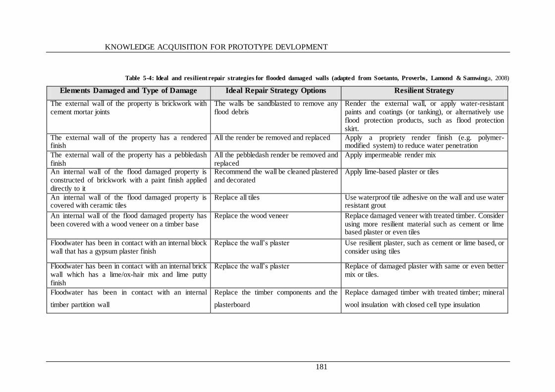
KNOWLEDGE ACQUISITION FOR PROTOTYPE DEVLOPMENT
181
Table 5-4: Ideal and resilient repair strategies for flooded damaged walls (adapted from Soetanto, Proverbs, Lamond & Samwinga, 2008)
Elements Damaged and Type of Damage Ideal Repair Strategy Options Resilient Strategy
The external wall of the property is brickwork with cement mortar joints
The walls be sandblasted to remove any flood debris
Render the external wall, or apply water-resistant paints and coatings (or tanking), or alternatively use flood protection products, such as flood protection skirt.
The external wall of the property has a rendered finish
All the render be removed and replaced Apply a propriety render finish (e.g. polymer-modified system) to reduce water penetration
The external wall of the property has a pebbledash finish
All the pebbledash render be removed and replaced
Apply impermeable render mix
An internal wall of the flood damaged property is constructed of brickwork with a paint finish applied directly to it
Recommend the wall be cleaned plastered and decorated
Apply lime-based plaster or tiles
An internal wall of the flood damaged property is covered with ceramic tiles
Replace all tiles Use waterproof tile adhesive on the wall and use water resistant grout
An internal wall of the flood damaged property has been covered with a wood veneer on a timber base
Replace the wood veneer Replace damaged veneer with treated timber. Consider using more resilient material such as cement or lime based plaster or even tiles
Floodwater has been in contact with an internal block wall that has a gypsum plaster finish
Replace the wall‘s plaster Use resilient plaster, such as cement or lime based, or consider using tiles
Floodwater has been in contact with an internal brick wall which has a lime/ox-hair mix and lime putty finish
Replace the wall‘s plaster Replace of damaged plaster with same or even better mix or tiles.
Floodwater has been in contact with an internal
timber partition wall
Replace the timber components and the
plasterboard
Replace damaged timber with treated timber; mineral
wool insulation with closed cell type insulation
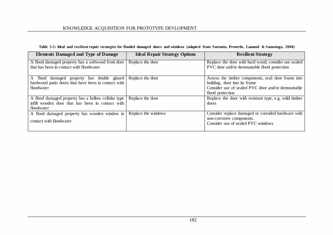
KNOWLEDGE ACQUISITION FOR PROTOTYPE DEVLOPMENT
182
Table 5-5: Ideal and resilient repair strategies for flooded damaged doors and windows (adapted from Soetanto, Proverbs, Lamond & Samwinga, 2008)
Elements Damaged and Type of Damage Ideal Repair Strategy Options Resilient Strategy
A flood damaged property has a softwood front door that has been in contact with floodwater
Replace the door Replace the door with hard wood; consider use sealed PVC door and/or demountable flood protection
A flood damaged property has double glazed hardwood patio doors that have been in contact with floodwater
Replace the door Assess the timber components, seal: door frame into building, door into its frame Consider use of sealed PVC door and/or demountable flood protection
A flood damaged property has a hollow cellular type infill wooden door that has been in contact with floodwater
Replace the door Replace the door with resistant type, e.g. solid timber doors
A flood damaged property has wooden window in
contact with floodwater
Replace the windows Consider replace damaged or corroded hardware with non-corrosive components. Consider use of sealed PVC windows

KNOWLEDGE ACQUISITION FOR PROTOTYPE DEVLOPMENT
183
Table 5-6: Ideal and resilient repair strategies for flooded damaged utilities (adapted from Soetanto, Proverbs, Lamond & Samwinga, 2008)
Elements Damaged and Type of Damage Ideal Repair Strategy Options Resilient Strategy
A flood damaged property has steel panel radiators that have
been in contact with floodwater
Replace the radiator and
valves
Qualified engineers to inspect the valves and radiators
before re-used.
A flood damaged property has a gas fired heater that has been
in contact with floodwater
Replace the heater Qualified engineers to inspect the heater before re-used.
A flood damaged property has a gas meter that has been in
contact with floodwater
Replace the meter Qualified engineers to inspect the gas meter before re-
used. move the gas meter to at least 1m above the floor
level or expected flood level
A flood damaged property has a wall-hung gas fire that has
been in contact with floodwater
The fire be placed Qualified engineers to inspect the fire before re-used.
The property has an electric circuit containing sockets that
have been partially submerged by floodwater
Completely replace this
installation
replace this installation and move to a higher level in the
structure so that cables drop from first-floor level down to
sockets
The dwelling has a wall-hung electric heater that has been
submerged by floodwater
The heater be replaced Qualified engineers to inspect the heater before re-used.
Move at least 1m above floor level, depending on the
predicted flood depth.
The dwelling has timber skirting boards Replace all skirting boards Replace skirting boards with more resilient materials such
as ceramic tiles and PVC The property has a staircase constructed from timber Complete replacement of the
stair caser
Use timber stair cases of solid timber construction.
The dwelling has built-in wall cupboards Completely replace the
cupboards
Consider repositioning cupboards above predicted future
flood level. Use more resilient materials such as PVC.
The dwelling has a fitted kitchen that has been partially Completely replace the
kitchen
Replace kitchen with water resistant alternatives (PVC) or
consider moving kitchen to first floor

KNOWLEDGE ACQUISITION FOR PROTOTYPE DEVLOPMENT
184
5.4 REPAIR OPTIONS USED IN THE PROPOSED SYSTEM
The repair options used for the proposed system were identified based on the documents as the examples given in Table 2.5, and other sources
used in the knowledge acquisition stage. The selected repair options are given below in the form of tables.
5.4.1 STANDARD REPAIR OPTIONS
The table below shows standard repair options used in, and recommended by, the system as standard repair options when the degree of
vulnerability assessed is low to medium.
Table 5-7: Standard repair options for basement
Flood Damaged
Element Repair Strategies Additional Information
Walls
1- replastering walls; do not use gypsum plasters 2- repairing floor screeds using dense cement/sand materials 3- positioning services in protected conduits, preferably at high level 4- replacing all damaged white goods and fittings
Refer to: BS 8102:1990 and BS 8000-4:1989
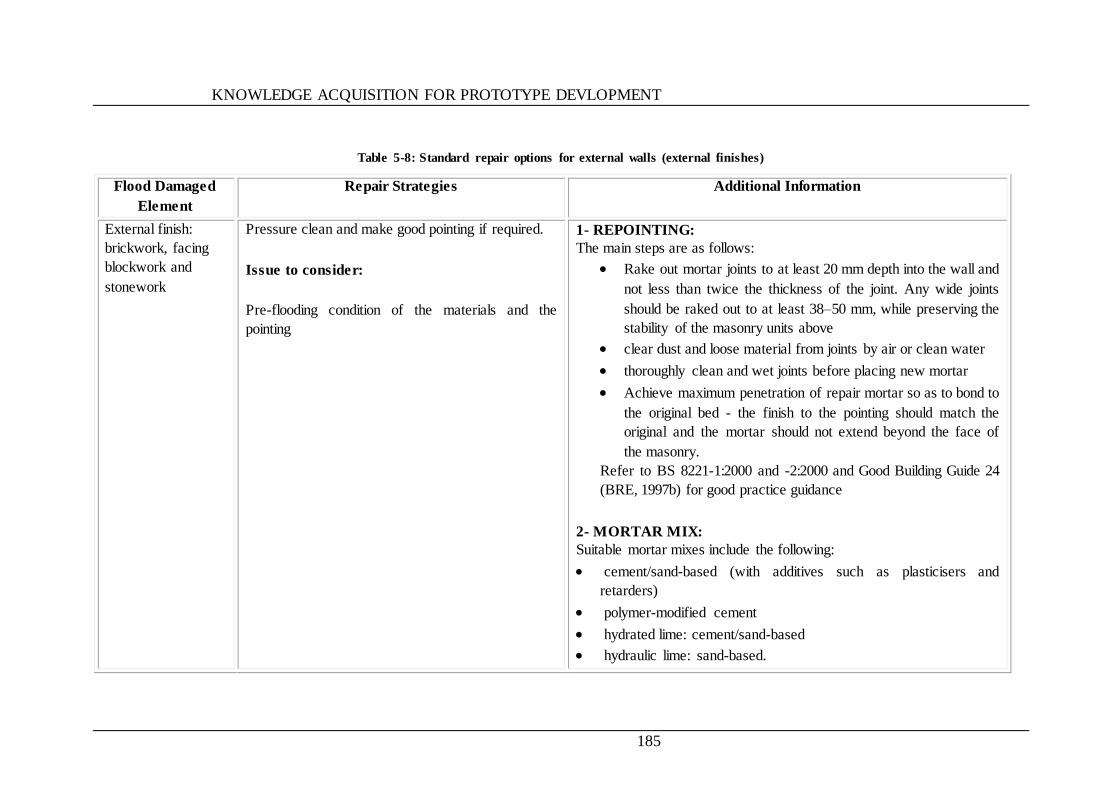
KNOWLEDGE ACQUISITION FOR PROTOTYPE DEVLOPMENT
185
Table 5-8: Standard repair options for external walls (external finishes)
Flood Damaged
Element
Repair Strategies Additional Information
External finish:
brickwork, facing
blockwork and
stonework
Pressure clean and make good pointing if required.
Issue to consider:
Pre-flooding condition of the materials and the
pointing
1- REPOINTING:
The main steps are as follows:
Rake out mortar joints to at least 20 mm depth into the wall and
not less than twice the thickness of the joint. Any wide joints
should be raked out to at least 38–50 mm, while preserving the
stability of the masonry units above
clear dust and loose material from joints by air or clean water
thoroughly clean and wet joints before placing new mortar
Achieve maximum penetration of repair mortar so as to bond to
the original bed - the finish to the pointing should match the
original and the mortar should not extend beyond the face of
the masonry.
Refer to BS 8221-1:2000 and -2:2000 and Good Building Guide 24
(BRE, 1997b) for good practice guidance
2- MORTAR MIX: Suitable mortar mixes include the following:
cement/sand-based (with additives such as plasticisers and
retarders)
polymer-modified cement
hydrated lime: cement/sand-based
hydraulic lime: sand-based.
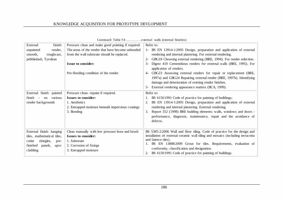
KNOWLEDGE ACQUISITION FOR PROTOTYPE DEVLOPMENT
186
Continued: Table 5.8……………external walls (external finishes)
External finish:
unpainted render,
smooth, roughcast,
pebbledash, Tyrolean
Pressure clean and make good pointing if required.
The areas of the render that have become unbonded
from the wall substrate should be replaced.
Issue to consider:
Pre-flooding condition of the render.
Refer to:
1- BS EN 13914-1:2005 Design, preparation and application of external
rendering and internal plastering. For external rendering.
2- GBG18 Choosing external rendering (BRE, 1994). For render selection.
3- Digest 410 Cementitious renders for external walls (BRE, 1995). For
application of renders.
4- GBG23 Assessing external renders for repair or replacement (BRE,
1997a) and GBG24 Repairing external render (BRE, 1997b). Identifying
damage and deterioration of existing render finishes.
5- External rendering appearance matters (BCA, 1999).
External finish: painted
finish - on various
render backgrounds
Pressure clean- repaint if required.
Issues to consider:
1. Aesthetics
2. Entrapped moisture beneath impervious coatings
3. Bonding
Refer to:
1. BS 6150:1991 Code of practice for painting of buildings;
2. BS EN 13914-1:2005 Design, preparation and application of external
rendering and internal plastering. External rendering.
3. Report 352 (1998) BRE building elements: walls, windows and doors -
performance, diagnosis, maintenance, repair and the avoidance of
defects.
External finish: hanging
tiles, mathematical tiles,
cedar shingles, pre-
finished panels, upvc
cladding
Clean manually with low pressure hose and brush
Issues to consider:
1. Substrate
2. Corrosion of fixings
3. Entrapped moisture
BS 5385-2:2006 Wall and floor tiling. Code of practice for the design and
installation of external ceramic wall tiling and mosaics (including terracotta
and faience tiles).
1. BS EN 13888:2009 Grout for tiles. Requirements, evaluation of
conformity, classification and designation.
2. BS 6150:1991 Code of practice for painting of buildings.
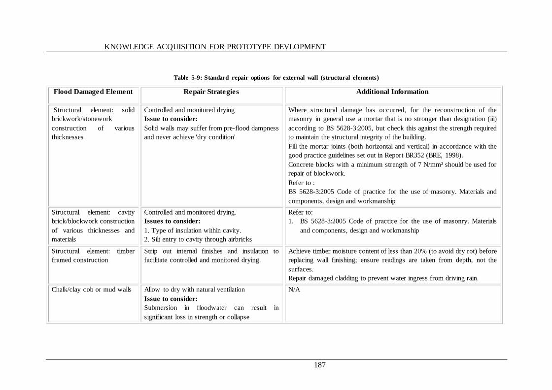
KNOWLEDGE ACQUISITION FOR PROTOTYPE DEVLOPMENT
187
Table 5-9: Standard repair options for external wall (structural elements)
Flood Damaged Element Repair Strategies Additional Information
Structural element: solid
brickwork/stonework
construction of various
thicknesses
Controlled and monitored drying
Issue to consider:
Solid walls may suffer from pre-flood dampness
and never achieve 'dry condition'
Where structural damage has occurred, for the reconstruction of the
masonry in general use a mortar that is no stronger than designation (iii)
according to BS 5628-3:2005, but check this against the strength required
to maintain the structural integrity of the building.
Fill the mortar joints (both horizontal and vertical) in accordance with the
good practice guidelines set out in Report BR352 (BRE, 1998).
Concrete blocks with a minimum strength of 7 N/mm² should be used for
repair of blockwork.
Refer to :
BS 5628-3:2005 Code of practice for the use of masonry. Materials and
components, design and workmanship
Structural element: cavity
brick/blockwork construction
of various thicknesses and
materials
Controlled and monitored drying.
Issues to consider:
1. Type of insulation within cavity.
2. Silt entry to cavity through airbricks
Refer to:
1. BS 5628-3:2005 Code of practice for the use of masonry. Materials
and components, design and workmanship
Structural element: timber
framed construction
Strip out internal finishes and insulation to
facilitate controlled and monitored drying.
Achieve timber moisture content of less than 20% (to avoid dry rot) before
replacing wall finishing; ensure readings are taken from depth, not the
surfaces.
Repair damaged cladding to prevent water ingress from driving rain.
Chalk/clay cob or mud walls Allow to dry with natural ventilation
Issue to consider:
Submersion in floodwater can result in
significant loss in strength or collapse
N/A
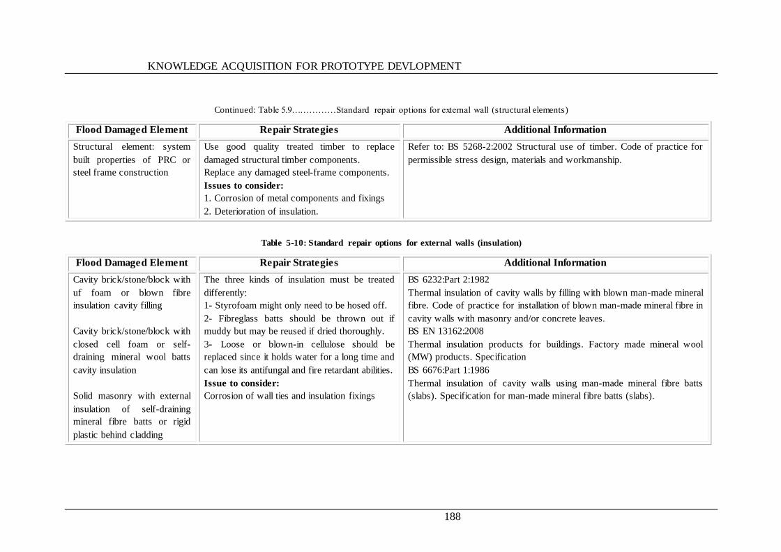
KNOWLEDGE ACQUISITION FOR PROTOTYPE DEVLOPMENT
188
Continued: Table 5.9……………Standard repair options for external wall (structural elements)
Flood Damaged Element Repair Strategies Additional Information
Structural element: system
built properties of PRC or
steel frame construction
Use good quality treated timber to replace
damaged structural timber components.
Replace any damaged steel-frame components.
Issues to consider:
1. Corrosion of metal components and fixings
2. Deterioration of insulation.
Refer to: BS 5268-2:2002 Structural use of timber. Code of practice for
permissible stress design, materials and workmanship.
Table 5-10: Standard repair options for external walls (insulation)
Flood Damaged Element Repair Strategies Additional Information
Cavity brick/stone/block with
uf foam or blown fibre
insulation cavity filling
Cavity brick/stone/block with
closed cell foam or self-
draining mineral wool batts
cavity insulation
Solid masonry with external
insulation of self-draining
mineral fibre batts or rigid
plastic behind cladding
The three kinds of insulation must be treated
differently:
1- Styrofoam might only need to be hosed off.
2- Fibreglass batts should be thrown out if
muddy but may be reused if dried thoroughly.
3- Loose or blown-in cellulose should be
replaced since it holds water for a long time and
can lose its antifungal and fire retardant abilities.
Issue to consider:
Corrosion of wall ties and insulation fixings
BS 6232:Part 2:1982
Thermal insulation of cavity walls by filling with blown man-made mineral
fibre. Code of practice for installation of blown man-made mineral fibre in
cavity walls with masonry and/or concrete leaves.
BS EN 13162:2008
Thermal insulation products for buildings. Factory made mineral wool
(MW) products. Specification
BS 6676:Part 1:1986
Thermal insulation of cavity walls using man-made mineral fibre batts
(slabs). Specification for man-made mineral fibre batts (slabs).
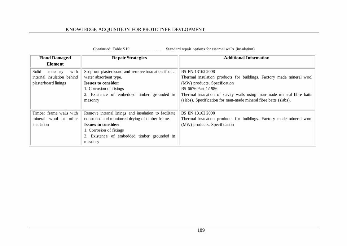
KNOWLEDGE ACQUISITION FOR PROTOTYPE DEVLOPMENT
189
Continued: Table 5.10 ……………………. Standard repair options for external walls (insulation)
Flood Damaged
Element
Repair Strategies Additional Information
Solid masonry with
internal insulation behind
plasterboard linings
Strip out plasterboard and remove insulation if of a
water absorbent type.
Issues to consider:
1. Corrosion of fixings
2. Existence of embedded timber grounded in
masonry
BS EN 13162:2008
Thermal insulation products for buildings. Factory made mineral wool
(MW) products. Specification
BS 6676:Part 1:1986
Thermal insulation of cavity walls using man-made mineral fibre batts
(slabs). Specification for man-made mineral fibre batts (slabs).
Timber frame walls with
mineral wool or other
insulation
Remove internal linings and insulation to facilitate
controlled and monitored drying of timber frame.
Issues to consider:
1. Corrosion of fixings
2. Existence of embedded timber grounded in
masonry
BS EN 13162:2008
Thermal insulation products for buildings. Factory made mineral wool
(MW) products. Specification
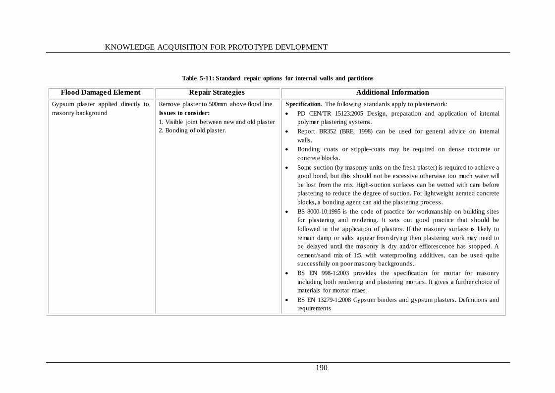
KNOWLEDGE ACQUISITION FOR PROTOTYPE DEVLOPMENT
190
Table 5-11: Standard repair options for internal walls and partitions
Flood Damaged Element Repair Strategies Additional Information
Gypsum plaster applied directly to
masonry background
Remove plaster to 500mm above flood line
Issues to consider:
1. Visible joint between new and old plaster
2. Bonding of old plaster.
Specification. The following standards apply to plasterwork:
PD CEN/TR 15123:2005 Design, preparation and application of internal
polymer plastering systems.
Report BR352 (BRE, 1998) can be used for general advice on internal
walls.
Bonding coats or stipple-coats may be required on dense concrete or
concrete blocks.
Some suction (by masonry units on the fresh plaster) is required to achieve a
good bond, but this should not be excessive otherwise too much water will
be lost from the mix. High-suction surfaces can be wetted with care before
plastering to reduce the degree of suction. For lightweight aerated concrete
blocks, a bonding agent can aid the plastering process.
BS 8000-10:1995 is the code of practice for workmanship on building sites
for plastering and rendering. It sets out good practice that should be
followed in the application of plasters. If the masonry surface is likely to
remain damp or salts appear from drying then plastering work may need to
be delayed until the masonry is dry and/or efflorescence has stopped. A
cement/sand mix of 1:5, with waterproofing additives, can be used quite
successfully on poor masonry backgrounds.
BS EN 998-1:2003 provides the specification for mortar for masonry
including both rendering and plastering mortars. It gives a further choice of
materials for mortar mixes.
BS EN 13279-1:2008 Gypsum binders and gypsum plasters. Definitions and
requirements
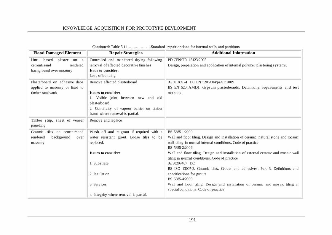
KNOWLEDGE ACQUISITION FOR PROTOTYPE DEVLOPMENT
191
Continued: Table 5.11 ………………Standard repair options for internal walls and partitions
Flood Damaged Element Repair Strategies Additional Information
Lime based plaster on a
cement/sand rendered
background over masonry
Controlled and monitored drying following
removal of affected decorative finishes
Issue to consider:
Loss of bonding
PD CEN/TR 15123:2005
Design, preparation and application of internal polymer plastering systems.
Plasterboard on adhesive dabs
applied to masonry or fixed to
timber studwork
Remove affected plasterboard
Issues to consider:
1. Visible joint between new and old
plasterboard;
2. Continuity of vapour barrier on timber
frame where removal is partial.
09/30185974 DC EN 520:2004/prA1:2009
BS EN 520 AMD1. Gypsum plasterboards. Definitions, requirements and test
methods
Timber strip, sheet of veneer
panelling
Remove and replace
Ceramic tiles on cement/sand
rendered background over
masonry
Wash off and re-grout if required with a
water resistant grout. Loose tiles to be
replaced.
Issues to consider:
1. Substrate
2. Insulation
3. Services
4. Integrity where removal is partial.
BS 5385-1:2009
Wall and floor tiling. Design and installation of ceramic, natural stone and mosaic
wall tiling in normal internal conditions. Code of practice
BS 5385-2:2006
Wall and floor tiling. Design and installation of external ceramic and mosaic wall
tiling in normal conditions. Code of practice
09/30207407 DC
BS ISO 13007-3. Ceramic tiles. Grouts and adhesives. Part 3. Definitions and
specifications for grouts
BS 5385-4:2009
Wall and floor tiling. Design and installation of ceramic and mosaic tiling in
special conditions. Code of practice
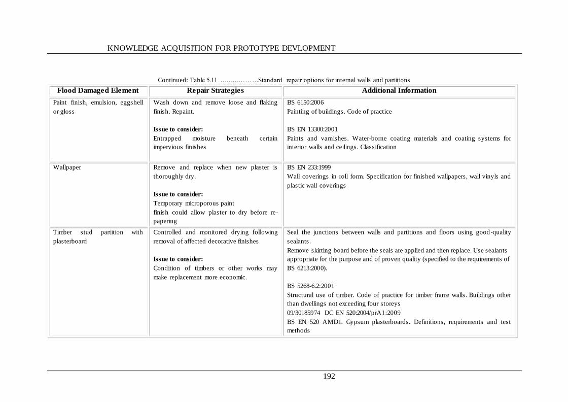
KNOWLEDGE ACQUISITION FOR PROTOTYPE DEVLOPMENT
192
Continued: Table 5.11 ………………Standard repair options for internal walls and partitions
Flood Damaged Element Repair Strategies Additional Information
Paint finish, emulsion, eggshell
or gloss
Wash down and remove loose and flaking
finish. Repaint.
Issue to consider:
Entrapped moisture beneath certain
impervious finishes
BS 6150:2006
Painting of buildings. Code of practice
BS EN 13300:2001
Paints and varnishes. Water-borne coating materials and coating systems for
interior walls and ceilings. Classification
Wallpaper
Remove and replace when new plaster is
thoroughly dry.
Issue to consider:
Temporary microporous paint
finish could allow plaster to dry before re-
papering
BS EN 233:1999
Wall coverings in roll form. Specification for finished wallpapers, wall vinyls and
plastic wall coverings
Timber stud partition with
plasterboard
Controlled and monitored drying following
removal of affected decorative finishes
Issue to consider:
Condition of timbers or other works may
make replacement more economic.
Seal the junctions between walls and partitions and floors using good-quality
sealants.
Remove skirting board before the seals are applied and then replace. Use sealants
appropriate for the purpose and of proven quality (specified to the requirements of
BS 6213:2000).
BS 5268-6.2:2001
Structural use of timber. Code of practice for timber frame walls. Buildings other
than dwellings not exceeding four storeys
09/30185974 DC EN 520:2004/prA1:2009
BS EN 520 AMD1. Gypsum plasterboards. Definitions, requirements and test
methods
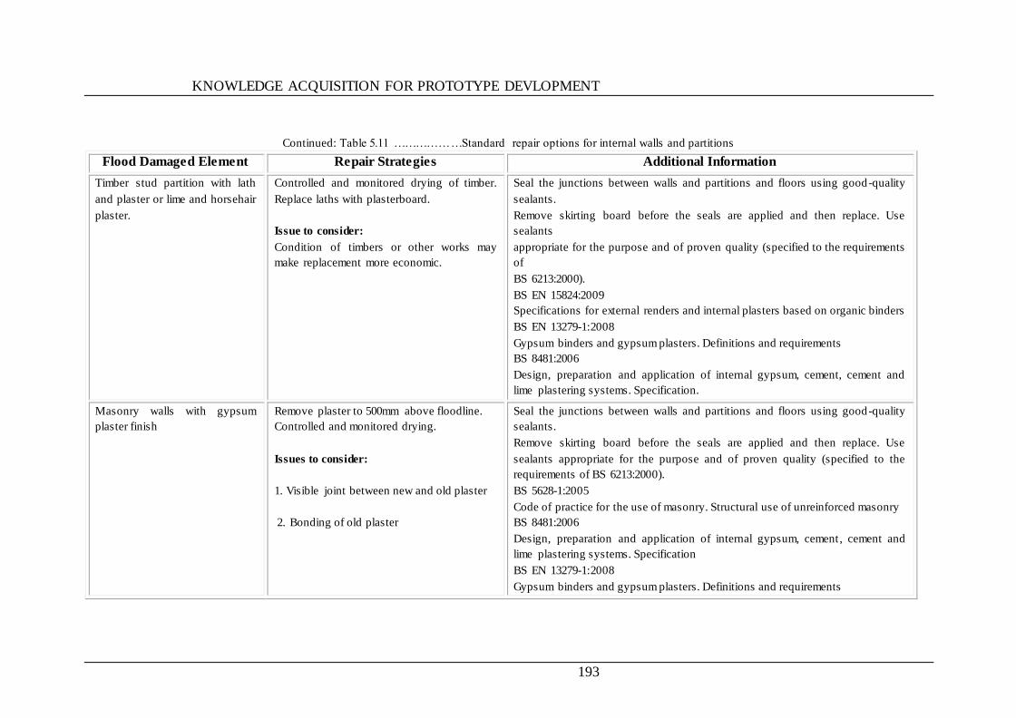
KNOWLEDGE ACQUISITION FOR PROTOTYPE DEVLOPMENT
193
Continued: Table 5.11 ………………Standard repair options for internal walls and partitions
Flood Damaged Element Repair Strategies Additional Information
Timber stud partition with lath
and plaster or lime and horsehair
plaster.
Controlled and monitored drying of timber.
Replace laths with plasterboard.
Issue to consider:
Condition of timbers or other works may
make replacement more economic.
Seal the junctions between walls and partitions and floors using good-quality
sealants.
Remove skirting board before the seals are applied and then replace. Use
sealants
appropriate for the purpose and of proven quality (specified to the requirements
of
BS 6213:2000).
BS EN 15824:2009
Specifications for external renders and internal plasters based on organic binders
BS EN 13279-1:2008
Gypsum binders and gypsum plasters. Definitions and requirements
BS 8481:2006
Design, preparation and application of internal gypsum, cement, cement and
lime plastering systems. Specification.
Masonry walls with gypsum
plaster finish
Remove plaster to 500mm above floodline.
Controlled and monitored drying.
Issues to consider:
1. Visible joint between new and old plaster
2. Bonding of old plaster
Seal the junctions between walls and partitions and floors using good-quality
sealants.
Remove skirting board before the seals are applied and then replace. Use
sealants appropriate for the purpose and of proven quality (specified to the
requirements of BS 6213:2000).
BS 5628-1:2005
Code of practice for the use of masonry. Structural use of unreinforced masonry
BS 8481:2006
Design, preparation and application of internal gypsum, cement , cement and
lime plastering systems. Specification
BS EN 13279-1:2008
Gypsum binders and gypsum plasters. Definitions and requirements

KNOWLEDGE ACQUISITION FOR PROTOTYPE DEVLOPMENT
194
Continued: Table 5.11 ………………Standard repair options for internal walls and partitions
Flood Damaged Element Repair Strategies Additional Information
Masonry walls with lime based
plaster finish on cement and
sand render.
Controlled and monitored drying following
removal of affected decorative finishes .
Use water resistant render and lime based
plaster or hydraulic lime coatings.
Issue to consider:
Loss of bonding
Seal the junctions between walls and partitions and floors using good-quality
sealants.
Remove skirting board before the seals are applied and then replace. Use sealants
appropriate for the purpose and of proven quality (specified to the requirements of
BS 6213:2000).
BS EN 13914-2:2005
Design, preparation and application of external rendering and internal plastering.
Design considerations and essential principles for internal plastering
PD CEN/TR 15123:2005
Design, preparation and application of internal polymer plastering systems
BS 8481:2006
Design, preparation and application of internal gypsum, cement, cement and lime
plastering systems. Specification
Metal framed partitions with
plasterboard sheets or faced
gypsum panels
Replace plasterboard or gypsum panels.
Issue to consider:
Corrosion of metal frame and fixings.
Seal the junctions between walls and partitions and floors using good-quality
sealants.
Remove skirting board before the seals are applied and then replace. Use sealants
appropriate for the purpose and of proven quality (specified to the requirements of
BS 6213:2000).
BS 7364:1990
Specification for galvanized steel studs and channels for stud and sheet partitions
and linings using screw fixed gypsum wallboards
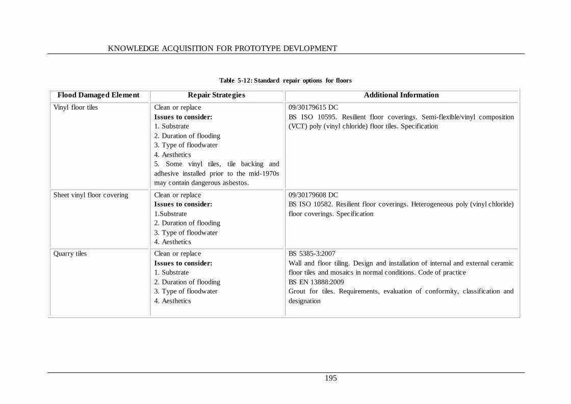
KNOWLEDGE ACQUISITION FOR PROTOTYPE DEVLOPMENT
195
Table 5-12: Standard repair options for floors
Flood Damaged Element Repair Strategies Additional Information
Vinyl floor tiles
Clean or replace
Issues to consider:
1. Substrate
2. Duration of flooding
3. Type of floodwater
4. Aesthetics
5. Some vinyl tiles, tile backing and
adhesive installed prior to the mid-1970s
may contain dangerous asbestos.
09/30179615 DC
BS ISO 10595. Resilient floor coverings. Semi-flexible/vinyl composition
(VCT) poly (vinyl chloride) floor tiles. Specification
Sheet vinyl floor covering
Clean or replace
Issues to consider:
1.Substrate
2. Duration of flooding
3. Type of floodwater
4. Aesthetics
09/30179608 DC
BS ISO 10582. Resilient floor coverings. Heterogeneous poly (vinyl chloride)
floor coverings. Specification
Quarry tiles
Clean or replace
Issues to consider:
1. Substrate
2. Duration of flooding
3. Type of floodwater
4. Aesthetics
BS 5385-3:2007
Wall and floor tiling. Design and installation of internal and external ceramic
floor tiles and mosaics in normal conditions. Code of practice
BS EN 13888:2009
Grout for tiles. Requirements, evaluation of conformity, classification and
designation
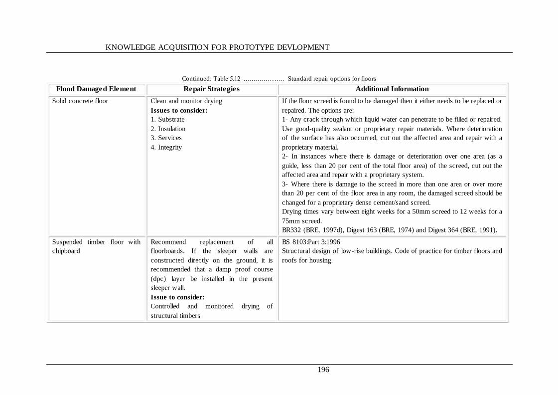
KNOWLEDGE ACQUISITION FOR PROTOTYPE DEVLOPMENT
196
Continued: Table 5.12 ……………….. Standard repair options for floors
Flood Damaged Element Repair Strategies Additional Information
Solid concrete floor Clean and monitor drying
Issues to consider:
1. Substrate
2. Insulation
3. Services
4. Integrity
If the floor screed is found to be damaged then it either needs to be replaced or
repaired. The options are:
1- Any crack through which liquid water can penetrate to be filled or repaired.
Use good-quality sealant or proprietary repair materials. Where deterioration
of the surface has also occurred, cut out the affected area and repair with a
proprietary material.
2- In instances where there is damage or deterioration over one area (as a
guide, less than 20 per cent of the total floor area) of the screed, cut out the
affected area and repair with a proprietary system.
3- Where there is damage to the screed in more than one area or over more
than 20 per cent of the floor area in any room, the damaged screed should be
changed for a proprietary dense cement/sand screed.
Drying times vary between eight weeks for a 50mm screed to 12 weeks for a
75mm screed.
BR332 (BRE, 1997d), Digest 163 (BRE, 1974) and Digest 364 (BRE, 1991).
Suspended timber floor with
chipboard
Recommend replacement of all
floorboards. If the sleeper walls are
constructed directly on the ground, it is
recommended that a damp proof course
(dpc) layer be installed in the present
sleeper wall.
Issue to consider:
Controlled and monitored drying of
structural timbers
BS 8103:Part 3:1996
Structural design of low-rise buildings. Code of practice for timber floors and
roofs for housing.
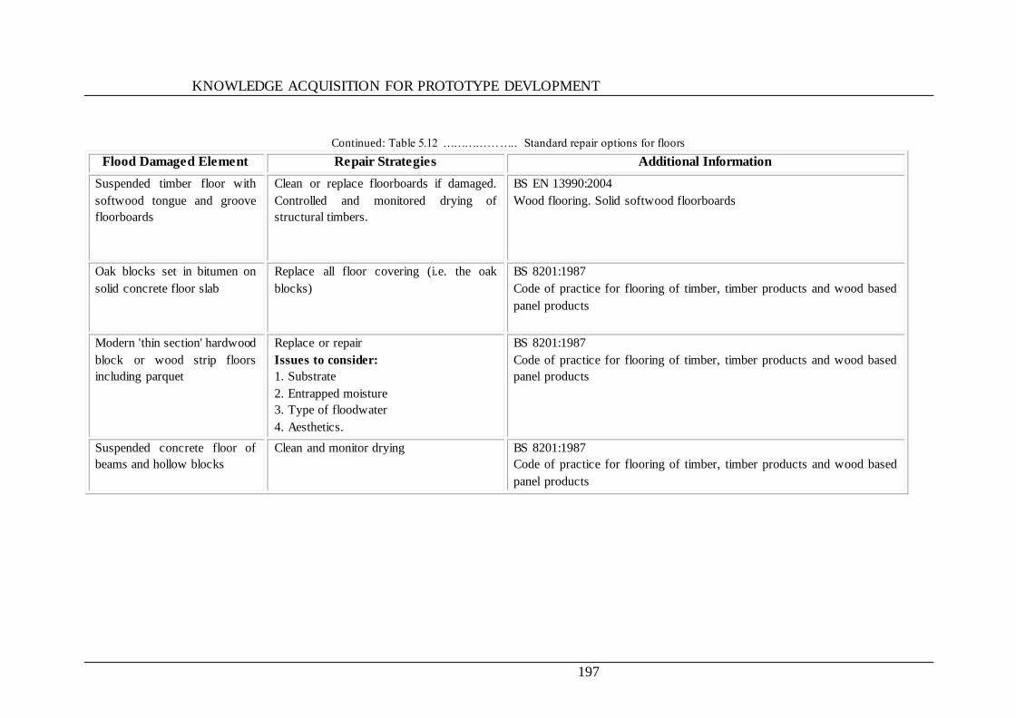
KNOWLEDGE ACQUISITION FOR PROTOTYPE DEVLOPMENT
197
Continued: Table 5.12 ……………….. Standard repair options for floors
Flood Damaged Element Repair Strategies Additional Information
Suspended timber floor with
softwood tongue and groove
floorboards
Clean or replace floorboards if damaged.
Controlled and monitored drying of
structural timbers.
BS EN 13990:2004
Wood flooring. Solid softwood floorboards
Oak blocks set in bitumen on
solid concrete floor slab
Replace all floor covering (i.e. the oak
blocks)
BS 8201:1987
Code of practice for flooring of timber, timber products and wood based
panel products
Modern 'thin section' hardwood
block or wood strip floors
including parquet
Replace or repair
Issues to consider:
1. Substrate
2. Entrapped moisture
3. Type of floodwater
4. Aesthetics.
BS 8201:1987
Code of practice for flooring of timber, timber products and wood based
panel products
Suspended concrete floor of
beams and hollow blocks
Clean and monitor drying BS 8201:1987
Code of practice for flooring of timber, timber products and wood based
panel products
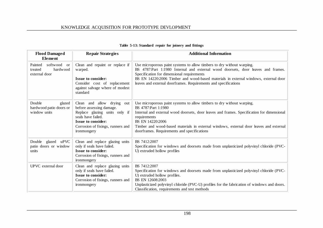
KNOWLEDGE ACQUISITION FOR PROTOTYPE DEVLOPMENT
198
Table 5-13: Standard repair for joinery and fittings
Flood Damaged
Element
Repair Strategies Additional Information
Painted softwood or
treated hardwood
external door
Clean and repaint or replace if
warped.
Issue to consider:
Consider cost of replacement
against salvage where of modest
standard
Use microporous paint systems to allow timbers to dry without warping.
BS 4787:Part 1:1980 Internal and external wood doorsets, door leaves and frames.
Specification for dimensional requirements
BS EN 14220:2006 Timber and wood-based materials in external windows, external door
leaves and external doorframes. Requirements and specifications
Double glazed
hardwood patio doors or
window units
Clean and allow drying out
before assessing damage.
Replace glazing units only if
seals have failed.
Issue to consider:
Corrosion of fixings, runners and
ironmongery
Use microporous paint systems to allow timbers to dry without warping.
BS 4787:Part 1:1980
Internal and external wood doorsets, door leaves and frames. Specification for dimensional
requirements
BS EN 14220:2006
Timber and wood-based materials in external windows, external door leaves and external
doorframes. Requirements and specifications
Double glazed uPVC
patio doors or window
units
Clean and replace glazing units
only if seals have failed.
Issue to consider:
Corrosion of fixings, runners and
ironmongery
BS 7412:2007
Specification for windows and doorsets made from unplasticized polyvinyl chloride (PVC-
U) extruded hollow profiles
UPVC external door
Clean and replace glazing units
only if seals have failed.
Issue to consider:
Corrosion of fixings, runners and
ironmongery
BS 7412:2007
Specification for windows and doorsets made from unplasticized polyvinyl chloride (PVC-
U) extruded hollow profiles.
BS EN 12608:2003
Unplasticized polyvinyl chloride (PVC-U) profiles for the fabrication of windows and doors.
Classification, requirements and test methods
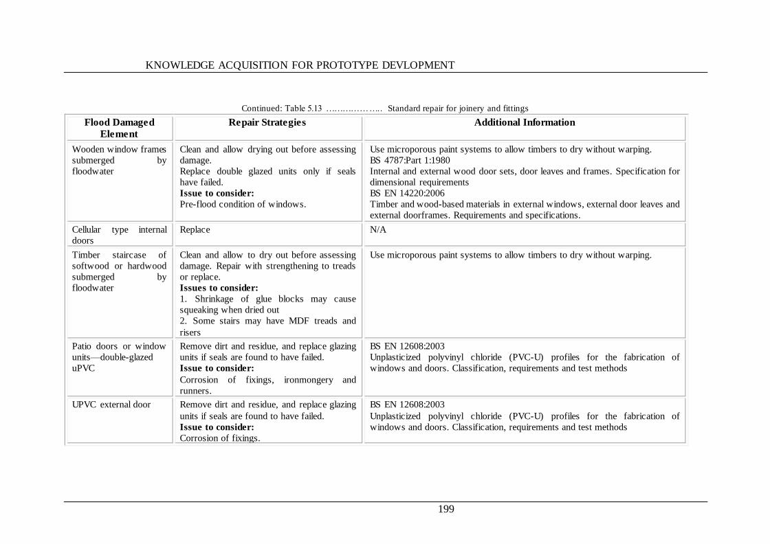
KNOWLEDGE ACQUISITION FOR PROTOTYPE DEVLOPMENT
199
Continued: Table 5.13 ……………….. Standard repair for joinery and fittings
Flood Damaged
Element
Repair Strategies Additional Information
Wooden window frames
submerged by
floodwater
Clean and allow drying out before assessing
damage.
Replace double glazed units only if seals
have failed.
Issue to consider:
Pre-flood condition of windows.
Use microporous paint systems to allow timbers to dry without warping.
BS 4787:Part 1:1980
Internal and external wood door sets, door leaves and frames. Specification for
dimensional requirements
BS EN 14220:2006
Timber and wood-based materials in external windows, external door leaves and
external doorframes. Requirements and specifications.
Cellular type internal
doors
Replace N/A
Timber staircase of
softwood or hardwood
submerged by
floodwater
Clean and allow to dry out before assessing
damage. Repair with strengthening to treads
or replace.
Issues to consider:
1. Shrinkage of glue blocks may cause
squeaking when dried out
2. Some stairs may have MDF treads and
risers
Use microporous paint systems to allow timbers to dry without warping.
Patio doors or window
units—double-glazed
uPVC
Remove dirt and residue, and replace glazing
units if seals are found to have failed.
Issue to consider:
Corrosion of fixings, ironmongery and
runners.
BS EN 12608:2003
Unplasticized polyvinyl chloride (PVC-U) profiles for the fabrication of
windows and doors. Classification, requirements and test methods
UPVC external door
Remove dirt and residue, and replace glazing
units if seals are found to have failed.
Issue to consider:
Corrosion of fixings.
BS EN 12608:2003
Unplasticized polyvinyl chloride (PVC-U) profiles for the fabrication of
windows and doors. Classification, requirements and test methods
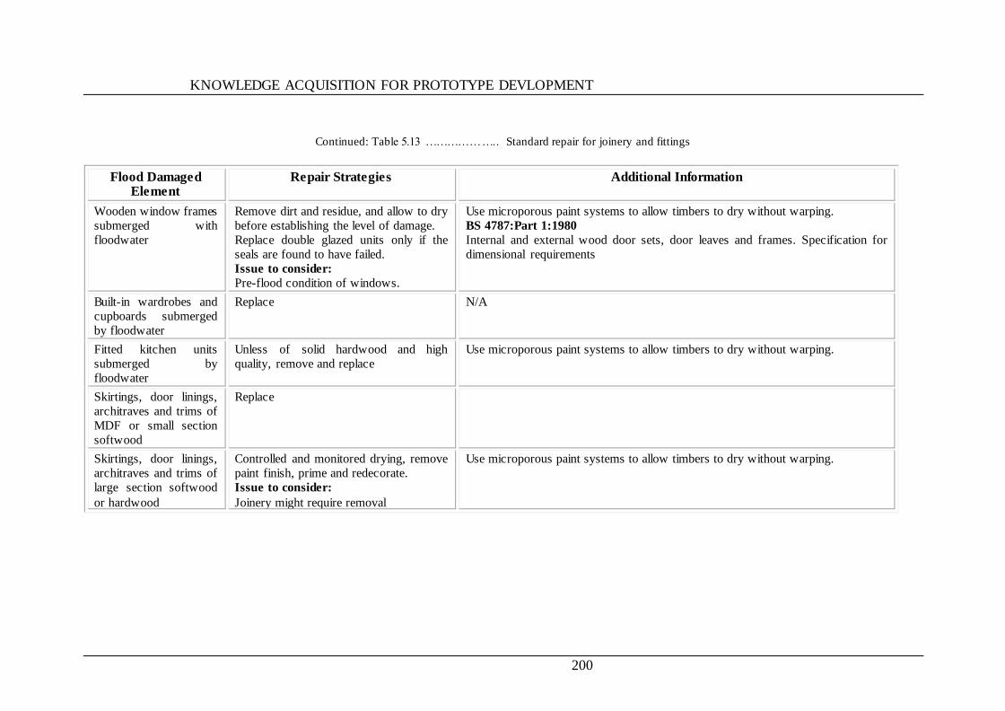
KNOWLEDGE ACQUISITION FOR PROTOTYPE DEVLOPMENT
200
Continued: Table 5.13 ……………….. Standard repair for joinery and fittings
Flood Damaged Element
Repair Strategies Additional Information
Wooden window frames
submerged with
floodwater
Remove dirt and residue, and allow to dry
before establishing the level of damage.
Replace double glazed units only if the
seals are found to have failed.
Issue to consider:
Pre-flood condition of windows.
Use microporous paint systems to allow timbers to dry without warping.
BS 4787:Part 1:1980
Internal and external wood door sets, door leaves and frames. Specification for
dimensional requirements
Built-in wardrobes and
cupboards submerged
by floodwater
Replace N/A
Fitted kitchen units
submerged by
floodwater
Unless of solid hardwood and high
quality, remove and replace
Use microporous paint systems to allow timbers to dry without warping.
Skirtings, door linings,
architraves and trims of
MDF or small section
softwood
Replace
Skirtings, door linings,
architraves and trims of
large section softwood
or hardwood
Controlled and monitored drying, remove
paint finish, prime and redecorate.
Issue to consider:
Joinery might require removal
Use microporous paint systems to allow timbers to dry without warping.
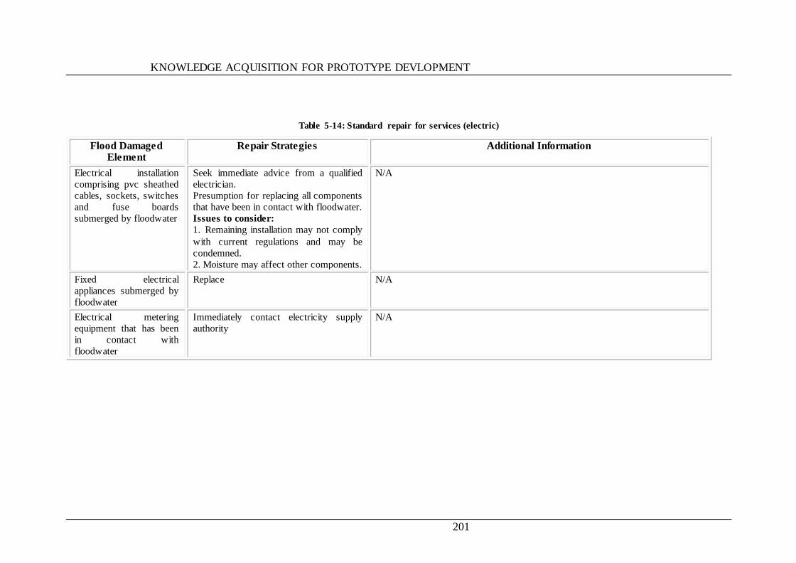
KNOWLEDGE ACQUISITION FOR PROTOTYPE DEVLOPMENT
201
Table 5-14: Standard repair for services (electric)
Flood Damaged Element
Repair Strategies Additional Information
Electrical installation
comprising pvc sheathed
cables, sockets, switches
and fuse boards
submerged by floodwater
Seek immediate advice from a qualified
electrician.
Presumption for replacing all components
that have been in contact with floodwater.
Issues to consider:
1. Remaining installation may not comply
with current regulations and may be
condemned.
2. Moisture may affect other components.
N/A
Fixed electrical
appliances submerged by
floodwater
Replace
N/A
Electrical metering
equipment that has been
in contact with
floodwater
Immediately contact electricity supply
authority
N/A
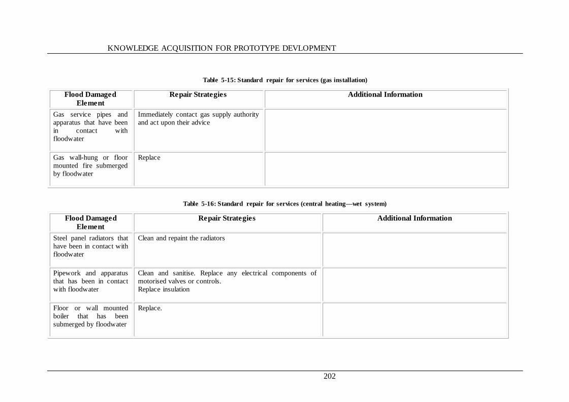
KNOWLEDGE ACQUISITION FOR PROTOTYPE DEVLOPMENT
202
Table 5-15: Standard repair for services (gas installation)
Flood Damaged
Element
Repair Strategies Additional Information
Gas service pipes and
apparatus that have been
in contact with
floodwater
Immediately contact gas supply authority
and act upon their advice
Gas wall-hung or floor
mounted fire submerged
by floodwater
Replace
Table 5-16: Standard repair for services (central heating—wet system)
Flood Damaged
Element
Repair Strategies Additional Information
Steel panel radiators that
have been in contact with
floodwater
Clean and repaint the radiators
Pipework and apparatus
that has been in contact
with floodwater
Clean and sanitise. Replace any electrical components of
motorised valves or controls.
Replace insulation
Floor or wall mounted
boiler that has been
submerged by floodwater
Replace.
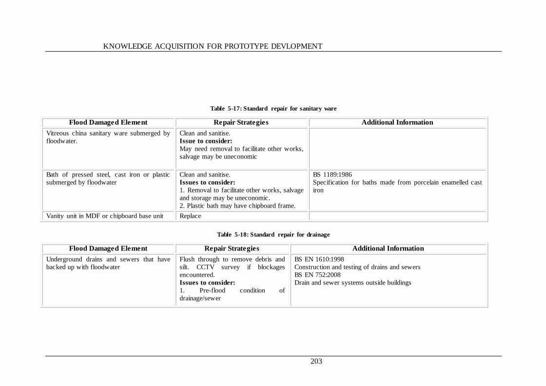
KNOWLEDGE ACQUISITION FOR PROTOTYPE DEVLOPMENT
203
Table 5-17: Standard repair for sanitary ware
Flood Damaged Element Repair Strategies Additional Information
Vitreous china sanitary ware submerged by
floodwater.
Clean and sanitise.
Issue to consider:
May need removal to facilitate other works,
salvage may be uneconomic
Bath of pressed steel, cast iron or plastic
submerged by floodwater
Clean and sanitise.
Issues to consider:
1. Removal to facilitate other works, salvage
and storage may be uneconomic.
2. Plastic bath may have chipboard frame.
BS 1189:1986
Specification for baths made from porcelain enamelled cast
iron
Vanity unit in MDF or chipboard base unit Replace
Table 5-18: Standard repair for drainage
Flood Damaged Element Repair Strategies Additional Information
Underground drains and sewers that have
backed up with floodwater
Flush through to remove debris and
silt. CCTV survey if blockages
encountered.
Issues to consider:
1. Pre-flood condition of
drainage/sewer
BS EN 1610:1998
Construction and testing of drains and sewers
BS EN 752:2008
Drain and sewer systems outside buildings

KNOWLEDGE ACQUISITION FOR PROTOTYPE DEVLOPMENT
204
Table 5-19: Resilient repair options for basement
Flood Damage
Element
Repair Strategy
Basement 1- when replastering walls do not use gypsum plasters
2- repair floor screeds using dense cement/sand materials
3- position services in protected conduits, preferably at high level
4- replace all damaged white goods and fittings.
Walls can be ‗tanked‘ externally both underground and normally up to a height of 1 metre above ground level.
Refer to: BS 8102:1990 and BS 8000-4:1989.
Facilities for pumping out basements. Three types of sump pump are commonly used.
1- Pedestal. This type of electric pump stands upright, with a motor a few feet above the pump, which is designed to get wet. It has a
float-activated switch
that turns the pump on when the water reaches a certain level.
2- Submersible. A submersible electric pump is installed underground and is designed to work underwater. It has the same float-activated
switch as the pedestal pump. While more expensive than the pedestal type, it is quieter and tends to have a longer life because its sealed,
oil-cooled motor is protected from moisture and dust.
3- Water-powered. This type of pump runs off the water pressure of the home plumbing system and also has the same float-activated
switch as the two types
above. It handles water at a much slower rate than the electric types, but requires no electricity to operate it. A water-powered pump can
be installed alongside an
electric pump and is generally used as a back-up system during a power failure.

KNOWLEDGE ACQUISITION FOR PROTOTYPE DEVLOPMENT
205
Table 5-20: Resilient repair options for external walls (external finishes)
Flood Damaged Element Resilient Repair Strategies
External finish: brickwork, facing blockwork and stonework N/A
External finish: unpainted render, smooth, roughcast, pebbledash, Tyrolean N/A
External finish: painted finish - on various render backgrounds
Pressure clean- repaint if required using a microporous coating
Issues to consider:
1. Aesthetics
2. Entrapped moisture beneath impervious coatings.
3. Bonding
External finish: hanging tiles, mathematical tiles, cedar shingles, pre-finished panels, upvc
cladding
N/A
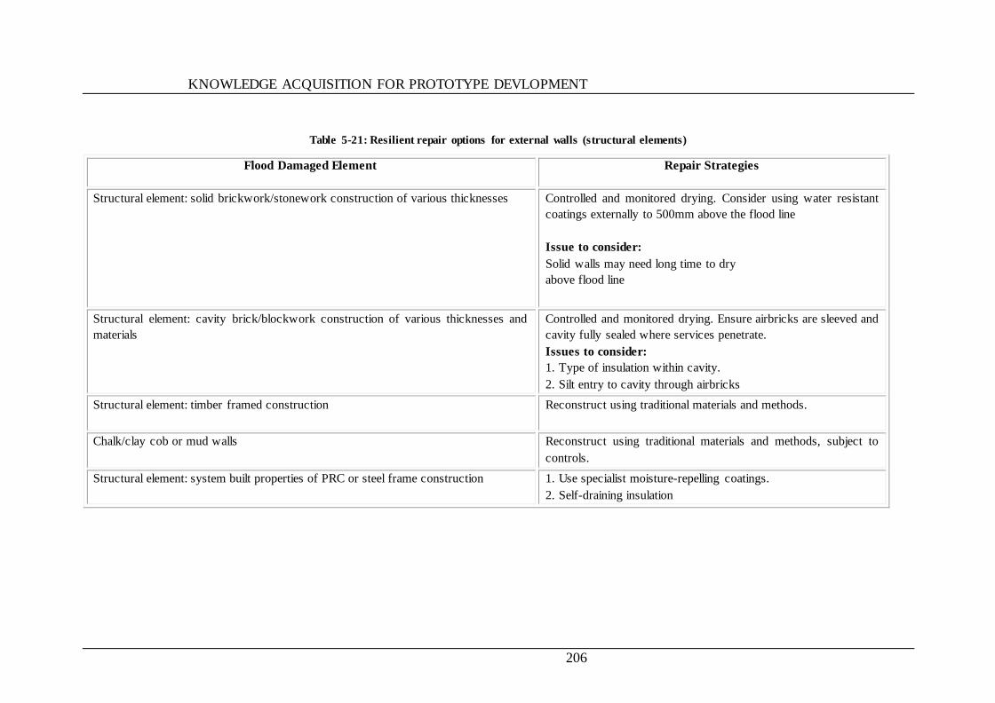
KNOWLEDGE ACQUISITION FOR PROTOTYPE DEVLOPMENT
206
Table 5-21: Resilient repair options for external walls (structural elements)
Flood Damaged Element Repair Strategies
Structural element: solid brickwork/stonework construction of various thicknesses Controlled and monitored drying. Consider using water resistant
coatings externally to 500mm above the flood line
Issue to consider:
Solid walls may need long time to dry
above flood line
Structural element: cavity brick/blockwork construction of various thicknesses and
materials
Controlled and monitored drying. Ensure airbricks are sleeved and
cavity fully sealed where services penetrate.
Issues to consider:
1. Type of insulation within cavity.
2. Silt entry to cavity through airbricks
Structural element: timber framed construction
Reconstruct using traditional materials and methods.
Chalk/clay cob or mud walls Reconstruct using traditional materials and methods, subject to
controls.
Structural element: system built properties of PRC or steel frame construction
1. Use specialist moisture-repelling coatings.
2. Self-draining insulation

KNOWLEDGE ACQUISITION FOR PROTOTYPE DEVLOPMENT
207
Table 5-22: Resilient repair options form external walls (insulation)
Flood Damaged Element Repair Strategies
Cavity brick/stone/block with uf or blown fibre insulation cavity filling Use closed cell insulation foam
Cavity brick/stone/block with closed cell foam or self-draining mineral wool batts cavity
insulation
Solid masonry with external insulation of self-draining mineral fibre batts or rigid plastic
behind cladding
Use stainless steel ties and fixings
Solid masonry with internal insulation behind plasterboard linings
1. Use stainless steel fixings.
2. Use low absorption insulating boards or semi-rigid self-
draining mineral wool batts
Timber frame walls with mineral wool or other insulation N/A
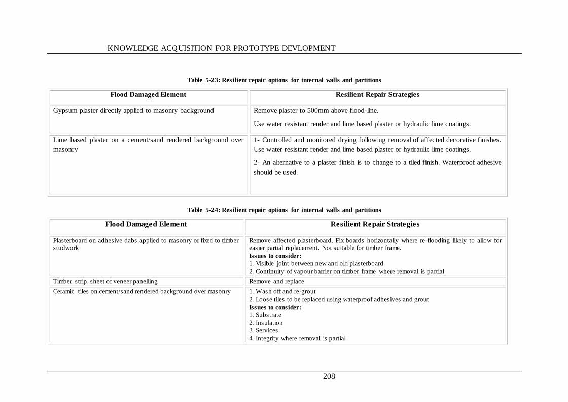
KNOWLEDGE ACQUISITION FOR PROTOTYPE DEVLOPMENT
208
Table 5-23: Resilient repair options for internal walls and partitions
Flood Damaged Element Resilient Repair Strategies
Gypsum plaster directly applied to masonry background
Remove plaster to 500mm above flood-line.
Use water resistant render and lime based plaster or hydraulic lime coatings.
Lime based plaster on a cement/sand rendered background over
masonry
1- Controlled and monitored drying following removal of affected decorative finishes.
Use water resistant render and lime based plaster or hydraulic lime coatings.
2- An alternative to a plaster finish is to change to a tiled finish. Waterproof adhesive
should be used.
Table 5-24: Resilient repair options for internal walls and partitions
Flood Damaged Element Resilient Repair Strategies
Plasterboard on adhesive dabs applied to masonry or fixed to timber
studwork
Remove affected plasterboard. Fix boards horizontally where re-flooding likely to allow for
easier partial replacement. Not suitable for timber frame.
Issues to consider:
1. Visible joint between new and old plasterboard
2. Continuity of vapour barrier on timber frame where removal is partial
Timber strip, sheet of veneer panelling Remove and replace
Ceramic tiles on cement/sand rendered background over masonry
1. Wash off and re-grout
2. Loose tiles to be replaced using waterproof adhesives and grout
Issues to consider:
1. Substrate
2. Insulation
3. Services
4. Integrity where removal is partial
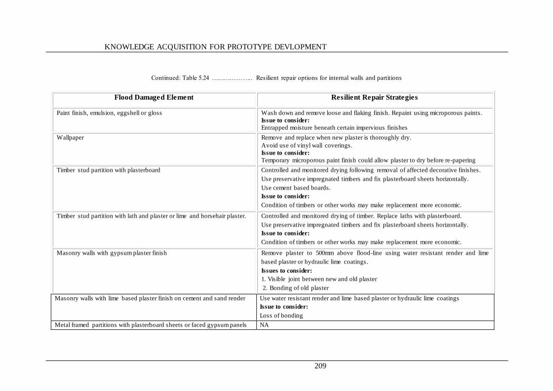
KNOWLEDGE ACQUISITION FOR PROTOTYPE DEVLOPMENT
209
Continued: Table 5.24 ……………….. Resilient repair options for internal walls and partitions
Flood Damaged Element Resilient Repair Strategies
Paint finish, emulsion, eggshell or gloss
Wash down and remove loose and flaking finish. Repaint using microporous paints.
Issue to consider:
Entrapped moisture beneath certain impervious finishes
Wallpaper
Remove and replace when new plaster is thoroughly dry.
Avoid use of vinyl wall coverings.
Issue to consider:
Temporary microporous paint finish could allow plaster to dry before re-papering
Timber stud partition with plasterboard
Controlled and monitored drying following removal of affected decorative finishes.
Use preservative impregnated timbers and fix plasterboard sheets horizontally.
Use cement based boards.
Issue to consider:
Condition of timbers or other works may make replacement more economic.
Timber stud partition with lath and plaster or lime and horsehair plaster. Controlled and monitored drying of timber. Replace laths with plasterboard.
Use preservative impregnated timbers and fix plasterboard sheets horizontally.
Issue to consider:
Condition of timbers or other works may make replacement more economic.
Masonry walls with gypsum plaster finish
Remove plaster to 500mm above flood-line using water resistant render and lime
based plaster or hydraulic lime coatings.
Issues to consider:
1. Visible joint between new and old plaster
2. Bonding of old plaster
Masonry walls with lime based plaster finish on cement and sand render Use water resistant render and lime based plaster or hydraulic lime coatings
Issue to consider:
Loss of bonding
Metal framed partitions with plasterboard sheets or faced gypsum panels NA
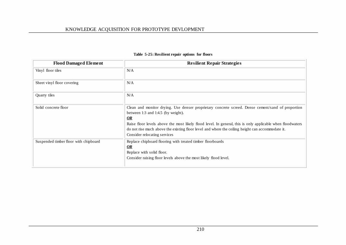
KNOWLEDGE ACQUISITION FOR PROTOTYPE DEVLOPMENT
210
Table 5-25: Resilient repair options for floors
Flood Damaged Element Resilient Repair Strategies
Vinyl floor tiles
N/A
Sheet vinyl floor covering
N/A
Quarry tiles N/A
Solid concrete floor
Clean and monitor drying. Use denser proprietary concrete screed. Dense cement/sand of proportion
between 1:3 and 1:4.5 (by weight).
OR
Raise floor levels above the most likely flood level. In general, this is only applicable when floodwaters
do not rise much above the existing floor level and where the ceiling height can accommodate it.
Consider relocating services
Suspended timber floor with chipboard
Replace chipboard flooring with treated timber floorboards
OR
Replace with solid floor.
Consider raising floor levels above the most likely flood level.
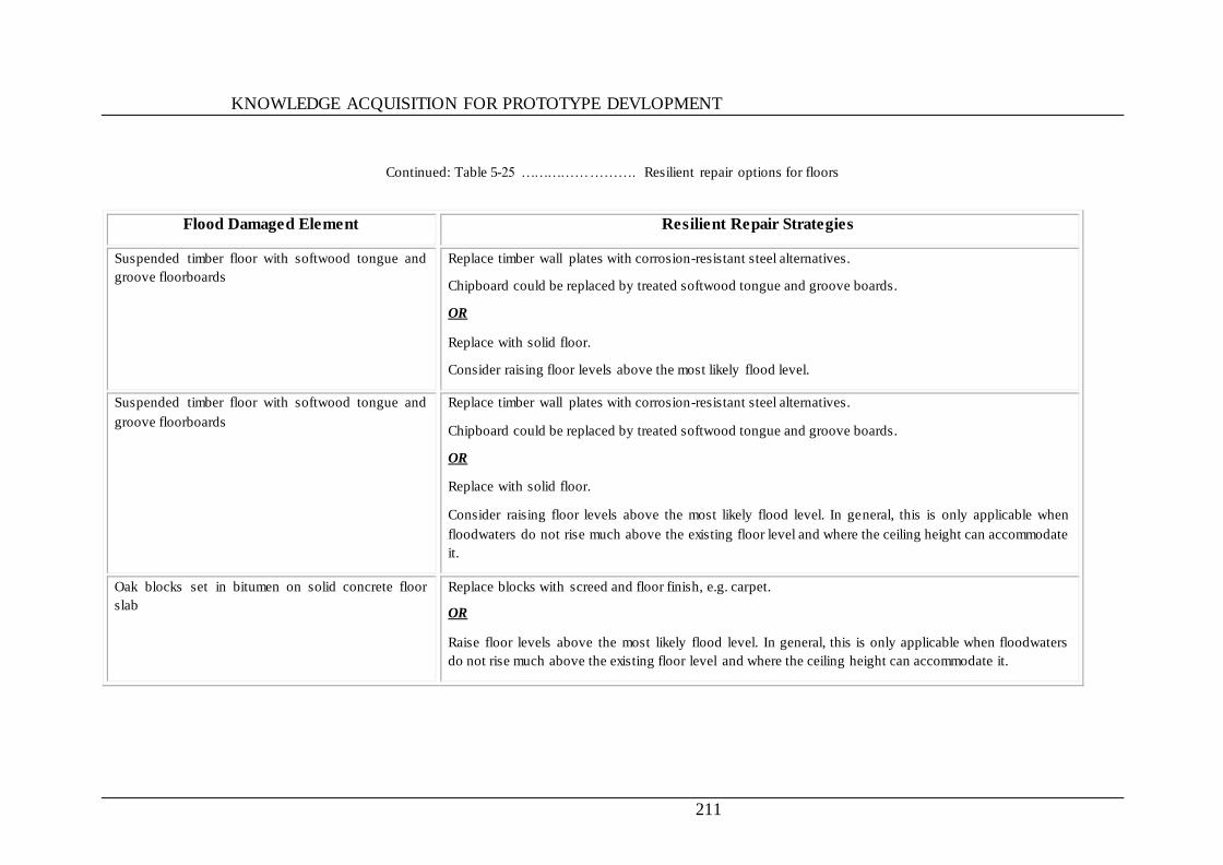
KNOWLEDGE ACQUISITION FOR PROTOTYPE DEVLOPMENT
211
Continued: Table 5-25 ……………………. Resilient repair options for floors
Flood Damaged Element Resilient Repair Strategies
Suspended timber floor with softwood tongue and
groove floorboards
Replace timber wall plates with corrosion-resistant steel alternatives.
Chipboard could be replaced by treated softwood tongue and groove boards.
OR
Replace with solid floor.
Consider raising floor levels above the most likely flood level.
Suspended timber floor with softwood tongue and
groove floorboards
Replace timber wall plates with corrosion-resistant steel alternatives.
Chipboard could be replaced by treated softwood tongue and groove boards.
OR
Replace with solid floor.
Consider raising floor levels above the most likely flood level. In general, this is only applicable when
floodwaters do not rise much above the existing floor level and where the ceiling height can accommodate
it.
Oak blocks set in bitumen on solid concrete floor
slab
Replace blocks with screed and floor finish, e.g. carpet.
OR
Raise floor levels above the most likely flood level. In general, this is only applicable when floodwaters
do not rise much above the existing floor level and where the ceiling height can accommodate it.
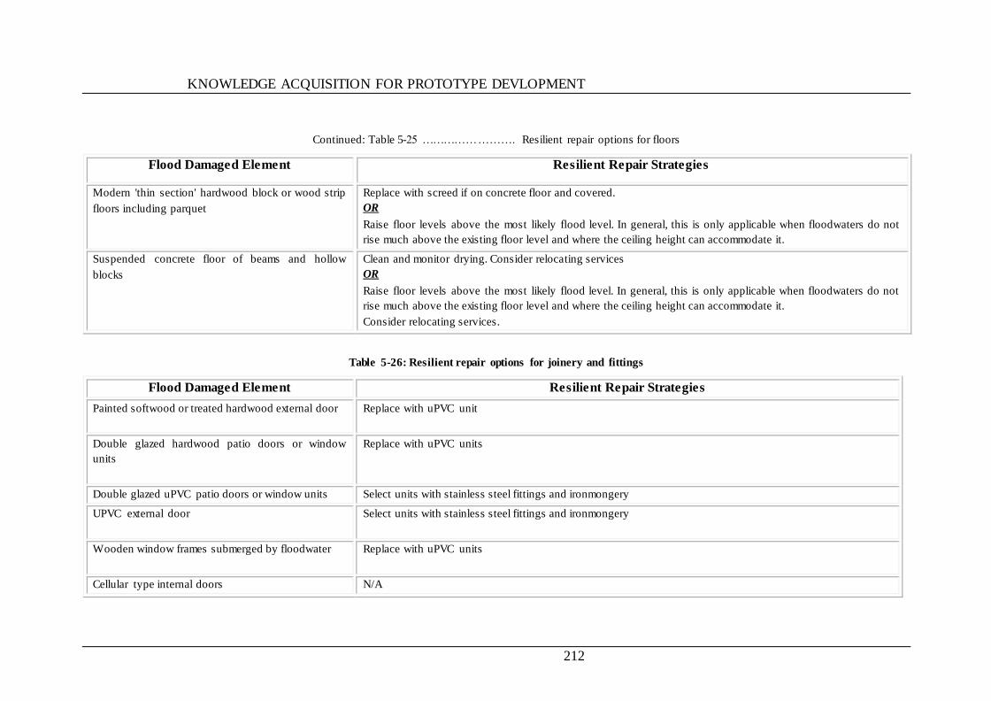
KNOWLEDGE ACQUISITION FOR PROTOTYPE DEVLOPMENT
212
Continued: Table 5-25 ……………………. Resilient repair options for floors
Flood Damaged Element Resilient Repair Strategies
Modern 'thin section' hardwood block or wood strip
floors including parquet
Replace with screed if on concrete floor and covered.
OR
Raise floor levels above the most likely flood level. In general, this is only applicable when floodwaters do not
rise much above the existing floor level and where the ceiling height can accommodate it.
Suspended concrete floor of beams and hollow
blocks
Clean and monitor drying. Consider relocating services
OR
Raise floor levels above the most likely flood level. In general, this is only applicable when floodwaters do not
rise much above the existing floor level and where the ceiling height can accommodate it.
Consider relocating services.
Table 5-26: Resilient repair options for joinery and fittings
Flood Damaged Element Resilient Repair Strategies
Painted softwood or treated hardwood external door
Replace with uPVC unit
Double glazed hardwood patio doors or window
units
Replace with uPVC units
Double glazed uPVC patio doors or window units Select units with stainless steel fittings and ironmongery
UPVC external door
Select units with stainless steel fittings and ironmongery
Wooden window frames submerged by floodwater
Replace with uPVC units
Cellular type internal doors N/A
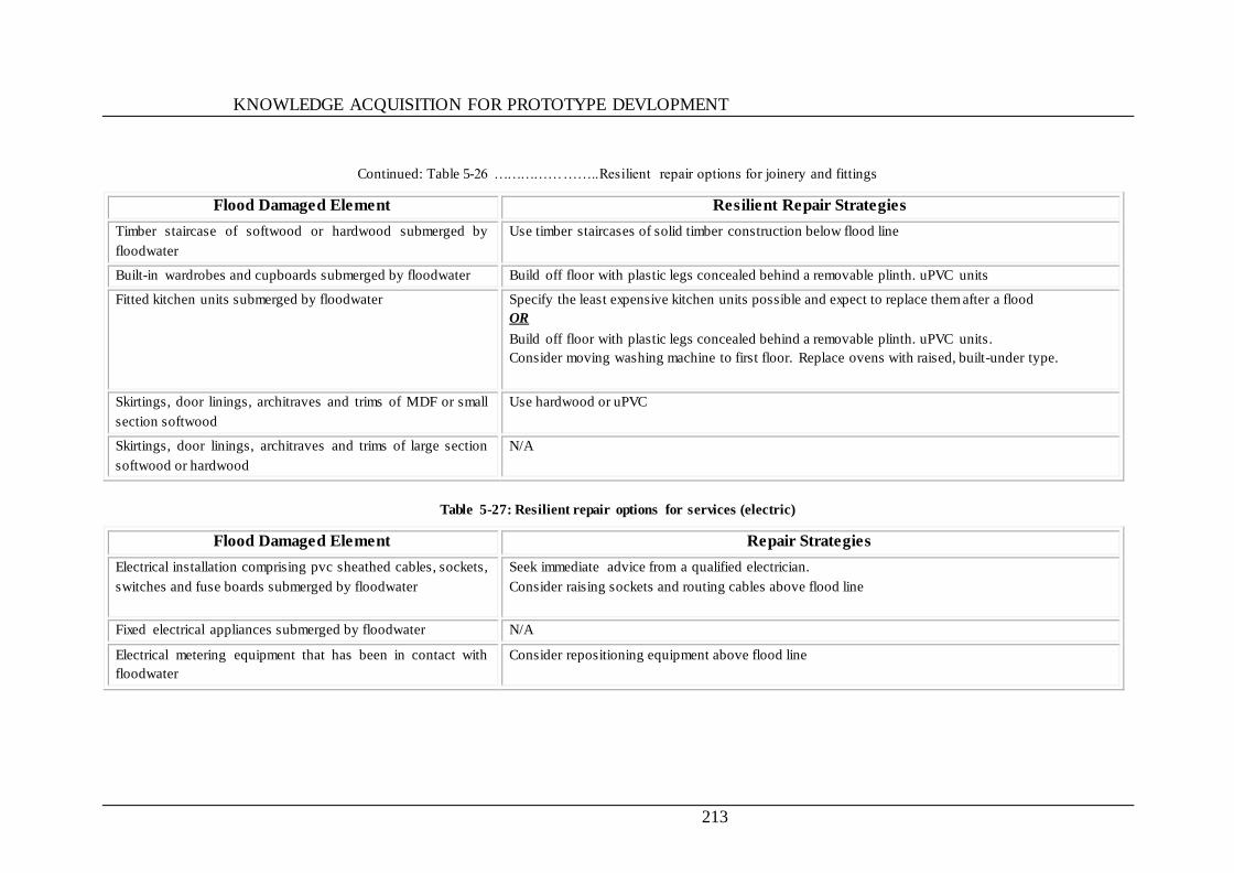
KNOWLEDGE ACQUISITION FOR PROTOTYPE DEVLOPMENT
213
Continued: Table 5-26 …………………..Resilient repair options for joinery and fittings
Flood Damaged Element Resilient Repair Strategies
Timber staircase of softwood or hardwood submerged by
floodwater
Use timber staircases of solid timber construction below flood line
Built-in wardrobes and cupboards submerged by floodwater Build off floor with plastic legs concealed behind a removable plinth. uPVC units
Fitted kitchen units submerged by floodwater Specify the least expensive kitchen units possible and expect to replace them after a flood
OR
Build off floor with plastic legs concealed behind a removable plinth. uPVC units.
Consider moving washing machine to first floor. Replace ovens with raised, built-under type.
Skirtings, door linings, architraves and trims of MDF or small
section softwood
Use hardwood or uPVC
Skirtings, door linings, architraves and trims of large section
softwood or hardwood
N/A
Table 5-27: Resilient repair options for services (electric)
Flood Damaged Element Repair Strategies
Electrical installation comprising pvc sheathed cables, sockets,
switches and fuse boards submerged by floodwater
Seek immediate advice from a qualified electrician.
Consider raising sockets and routing cables above flood line
Fixed electrical appliances submerged by floodwater N/A
Electrical metering equipment that has been in contact with
floodwater
Consider repositioning equipment above flood line
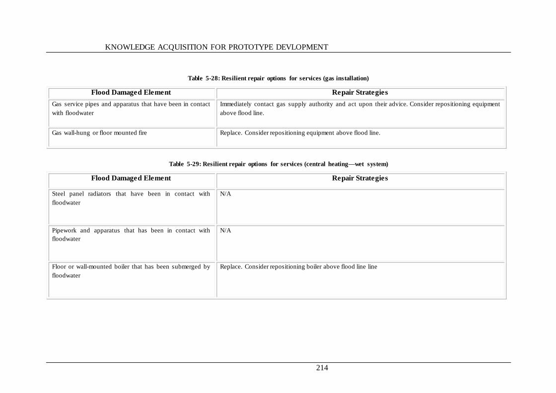
KNOWLEDGE ACQUISITION FOR PROTOTYPE DEVLOPMENT
214
Table 5-28: Resilient repair options for services (gas installation)
Flood Damaged Element Repair Strategies
Gas service pipes and apparatus that have been in contact
with floodwater
Immediately contact gas supply authority and act upon their advice. Consider repositioning equipment
above flood line.
Gas wall-hung or floor mounted fire
Replace. Consider repositioning equipment above flood line.
Table 5-29: Resilient repair options for services (central heating—wet system)
Flood Damaged Element Repair Strategies
Steel panel radiators that have been in contact with
floodwater
N/A
Pipework and apparatus that has been in contact with
floodwater
N/A
Floor or wall-mounted boiler that has been submerged by
floodwater
Replace. Consider repositioning boiler above flood line line
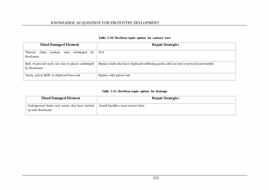
KNOWLEDGE ACQUISITION FOR PROTOTYPE DEVLOPMENT
215
Table 5-30: Resilient repair options for sanitary ware
Flood Damaged Element Repair Strategies
Vitreous china sanitary ware submerged by
floodwater.
N/A
Bath of pressed steel, cast iron or plastic submerged
by floodwater
Replace baths that have chipboard stiffening panels with cast iron or pressed steel models.
Vanity unit in MDF or chipboard base unit Replace with plastic unit
Table 5-31: Resilient repair options for drainage
Flood Damaged Element Repair Strategies
Underground drains and sewers that have backed
up with floodwater
Install backflow (non-return) valve.
KNOWLEDGE ACQUISITION FOR PROTOTYPE DEVLOPMENT
216
5.5 SUMMARY
This chapter discussed the method used for knowledge acquisition and the results of
surveys carried out used to investigate the factors contribute to vulnerability of
residential building to flood damage. Also, state the repair options based on the
documents that provide technical information for this purpose summarized in the form
of tables and charts. Finally, given the standard and resilient repair options that used by
the prototype system which produced during the knowledge acquisition stage. The next
chapter will discuss the development and operation of the prototype system.
DEVELOPMENT AND OPERATION OF THE PROTOTYPE SYSTEM
217
CHAPTER 6 DEVELOPMENT AND OPERATION OF
THE PROTOTYPE SYSTEM
6.1 INTRODUCTION
This chapter begins by providing a review of the prototype system‘s functions and
architecture. It then goes on to describe in detail the process of developing the prototype
system. The operation of the system is also demonstrated, with its main features
highlighted.
6.2 DEGREE OF VULNERABILITY AND REMEDIATION
ASSESSMENT OF FLOODED RESIDENTIAL BUILDING
SYSTEM (VRAFRBS)
6.2.1 THE FUNCTIONS OF THE SYSTEM
The prototype knowledge base system named ‗Vulnerability and Remediation
Assessment of Flooded Residential Building System (VRAFRBS)‘ are aimed at helping
some of the stakeholders involved in the remediation of residential buildings subjected
to flood damage—especially insurance companies, flood remediation contractors and
engineers. The main functions to be providing by the system are:
To assess and evaluate the vulnerability of residential buildings subjected to
flood damage;
To help in damage assessment of building foundations and gives guides to
damage repair;
DEVELOPMENT AND OPERATION OF THE PROTOTYPE SYSTEM
218
To help in the selection of repair methods and procedures of remediation of
each building elements damaged by flood;
To suggest resilience repair methods and material could be used in the
remediation of residential building damaged by flood where it is applicable; and
To help in establish a basic for flooded residential building risk assessment and
repair.
6.2.2 THE SYSTEM ARCHITECTURE
The system consists of five main modules:
Vulnerability assessment: This module is responsible for accepting users‘ input
regarding the case of study as well as users‘ answers in response to a predefined
set of questions to help the system in evaluating the degree of vulnerability.
Applying the user response to those questions, using its logical algorithm, the
module will evaluate the case and indicate its degree of vulnerability, and
accordingly save the case details and the assessment result in the database.
Remediation option selection: The function of this module is to suggest the
user the repair option to repair the damaged element to the case in hand
according to its degree of vulnerability, this module fetches the information from
the database each and every time the user is working on any particular case.
Foundation damage assessment: This subsystem is used to assess the damage
caused by flood, and suggest repair options for different situations.
Reports: This module is utilising Crystal Reports engine to publish different
reports from the database to the user, this reports are very useful for the user to
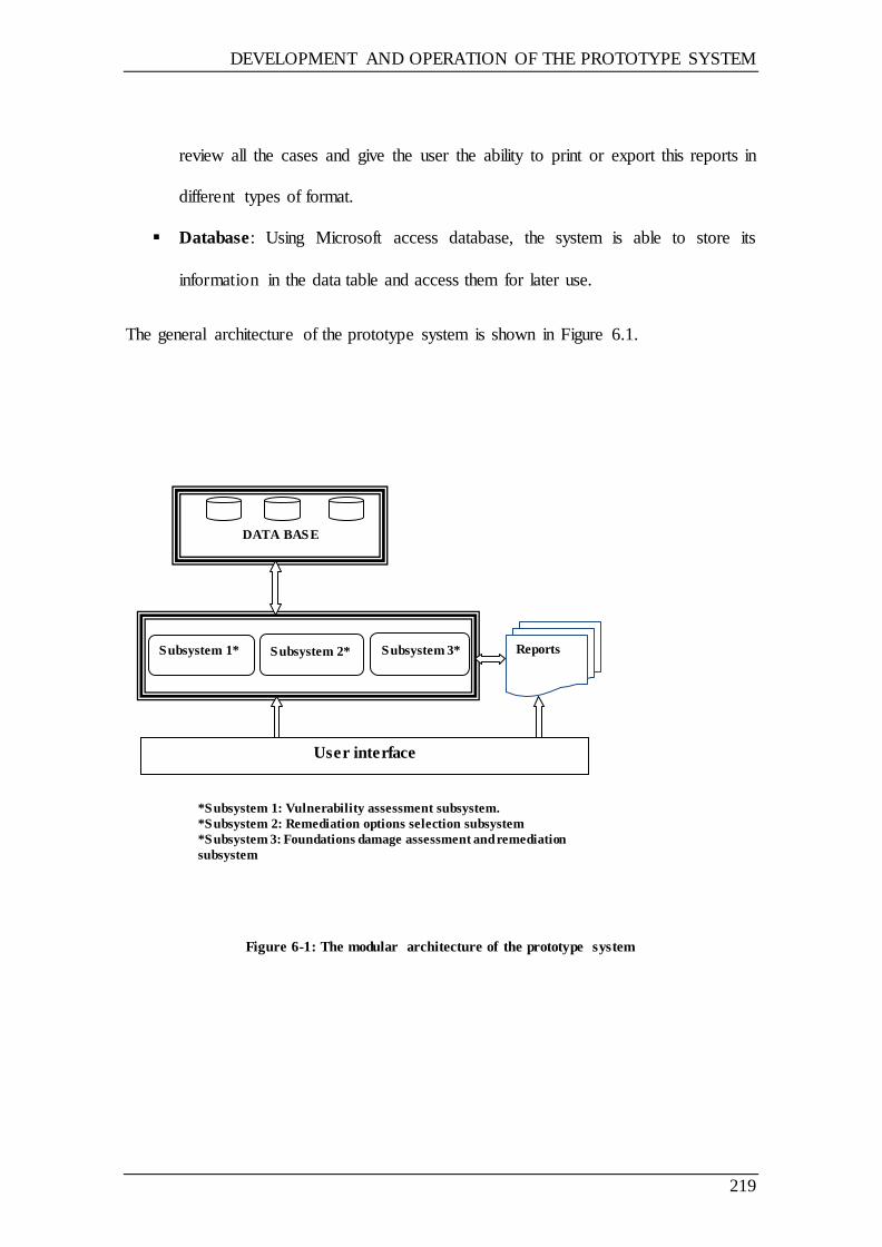
DEVELOPMENT AND OPERATION OF THE PROTOTYPE SYSTEM
219
review all the cases and give the user the ability to print or export this reports in
different types of format.
Database: Using Microsoft access database, the system is able to store its
information in the data table and access them for later use.
The general architecture of the prototype system is shown in Figure 6.1.
Figure 6-1: The modular architecture of the prototype system
DATA BASE
Reports
User interface
Subsystem 1* Subsystem 2* Subsystem 3*
*Subsystem 1: Vulnerability assessment subsystem.
*Subsystem 2: Remediation options selection subsystem
*Subsystem 3: Foundations damage assessment and remediation
subsystem
DEVELOPMENT AND OPERATION OF THE PROTOTYPE SYSTEM
220
6.2.3 SYSTEM DEVELOPMENT
6.2.3.1 Building the VRAFRBS
Since the system is targeted for use in the assessment and repair of flooded and
damaged buildings, and owing to the fact that most of the users will be site-based staff,
practicality and transportability are important. Hence, this prototype system was
developed using Microsoft Visual Studio, written in VB.NET, with dependence on
Microsoft Access to store its data. This makes it ideal for running on any Microsoft
operating system, which is both user-friendly and widely used.
In this research, the rapid prototyping methodology has been implemented in order to
develop the prototype system. The rapid prototyping is a strategy used in system
developing were preliminary system is developed in a short time, tested and accordingly
improved in several repeated until the final model is ready (see Chapter 2, Section 2.3.2
for more details).
6.2.3.2 System design
The prototype knowledge base system comprises three subsystems: the Degree of
vulnerability assessment, Remediation options, and Foundation damage assessment, as
shown in Figure 6.2 and Figure 6.3. With this in mind, the degree of vulnerability
assessment subsystem is used to determine the degree of vulnerability of the building
subjected to flood damage in relation to a number of factors contributing to flood
damage. The remediation options subsystem introduces the remediation options for
repairing different building elements; the procedure is either through using the
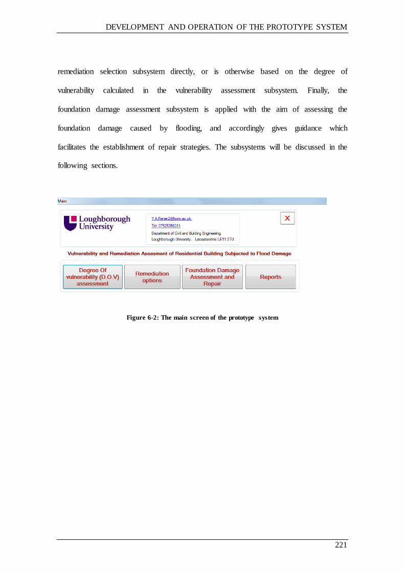
DEVELOPMENT AND OPERATION OF THE PROTOTYPE SYSTEM
221
remediation selection subsystem directly, or is otherwise based on the degree of
vulnerability calculated in the vulnerability assessment subsystem. Finally, the
foundation damage assessment subsystem is applied with the aim of assessing the
foundation damage caused by flooding, and accordingly gives guidance which
facilitates the establishment of repair strategies. The subsystems will be discussed in the
following sections.
Figure 6-2: The main screen of the prototype system
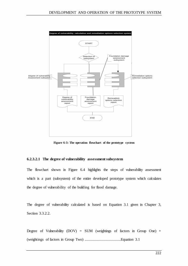
DEVELOPMENT AND OPERATION OF THE PROTOTYPE SYSTEM
222
Degree of vulnerability calculation and remediation options selection system
START
Selection of
subsystem
Remeadioin
options selection
report
Degree of
vulnerability
assessment
report
END
Remediation options
selection subsystem
Degree of vulnerability
Assessment subsytem
Foundation damage
assessment
subsystem
Foundation
damage
assessment
report
Figure 6-3: The operation flowchart of the prototype system
6.2.3.2.1 The degree of vulnerability assessment subsystem
The flowchart shown in Figure 6.4 highlights the steps of vulnerability assessment
which is a part (subsystem) of the entire developed prototype system which calculates
the degree of vulnerability of the building for flood damage.
The degree of vulnerability calculated is based on Equation 3.1 given in Chapter 3,
Section 3.3.2.2.
Degree of Vulnerability (DOV) = SUM (weightings of factors in Group One) +
(weightings of factors in Group Two) ......................................Equation 3.1
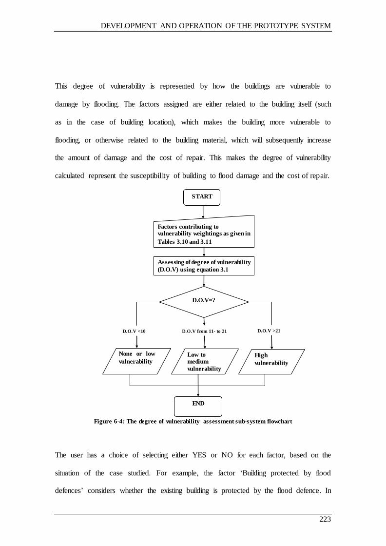
DEVELOPMENT AND OPERATION OF THE PROTOTYPE SYSTEM
223
This degree of vulnerability is represented by how the buildings are vulnerable to
damage by flooding. The factors assigned are either related to the building itself (such
as in the case of building location), which makes the building more vulnerable to
flooding, or otherwise related to the building material, which will subsequently increase
the amount of damage and the cost of repair. This makes the degree of vulnerability
calculated represent the susceptibility of building to flood damage and the cost of repair.
Figure 6-4: The degree of vulnerability assessment sub-system flowchart
The user has a choice of selecting either YES or NO for each factor, based on the
situation of the case studied. For example, the factor ‗Building protected by flood
defences‘ considers whether the existing building is protected by the flood defence. In
High
vulnerability
Low to medium
vulnerability
None or low
vulnerability
START
Factors contributing to vulnerability weightings as given in
Tables 3.10 and 3.11
Assessing of degree of vulnerability
(D.O.V) using equation 3.1
D.O.V=?
END
D.O.V from 11- to 21 D.O.V >21 D.O.V <10

DEVELOPMENT AND OPERATION OF THE PROTOTYPE SYSTEM
224
this regard, the answer will be either (YES) or (NO) as to whether there is flood
defence.
The factors are given a value based on the user selection, with each factor falling into
one of three values:
1- If the user selects (NO) and the factor is assigned either as important or very
important factor, the value given to this factor in this case will then be ‗0‘ and will
be used in the degree of vulnerability calculation.
2- If the user selects (YES) and the factor is assigned as an important factor, the value
given in this case will then be ‗1‘ and will be used in the degree of vulnerability
calculation.
3- If the user selects (YES) and the factor assigned is very important factor, then the
value given in this case will be ‗2‘ and will be used in the degree of vulnerability
calculation.
As can be seen from the previous example, if the answer was (YES), the values given
will be ‗1‘ because this factor was assigned an important factor.
Table 6.1 shows the values given to each factor based on user selection either (YES) or
(NO).
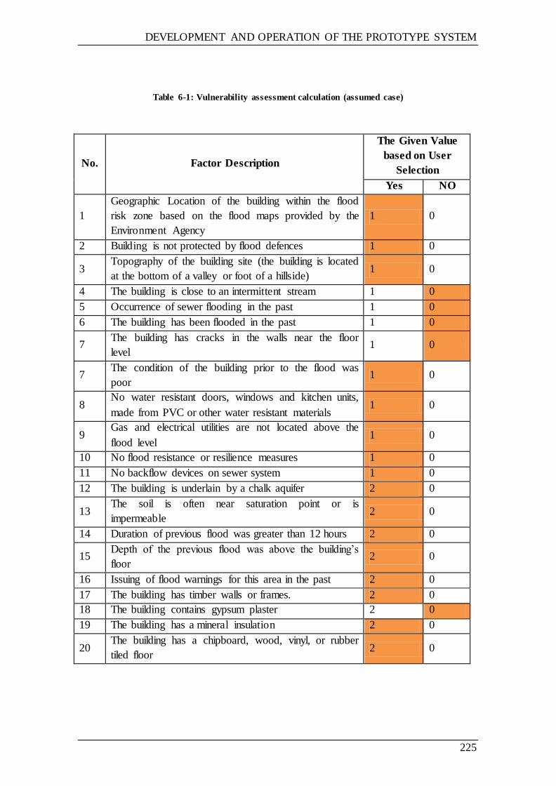
DEVELOPMENT AND OPERATION OF THE PROTOTYPE SYSTEM
225
Table 6-1: Vulnerability assessment calculation (assumed case)
No. Factor Description
The Given Value
based on User
Selection
Yes NO
1
Geographic Location of the building within the flood
risk zone based on the flood maps provided by the
Environment Agency
1 0
2 Building is not protected by flood defences 1 0
3 Topography of the building site (the building is located
at the bottom of a valley or foot of a hillside) 1 0
4 The building is close to an intermittent stream 1 0
5 Occurrence of sewer flooding in the past 1 0
6 The building has been flooded in the past 1 0
7 The building has cracks in the walls near the floor
level 1 0
7 The condition of the building prior to the flood was
poor 1 0
8 No water resistant doors, windows and kitchen units,
made from PVC or other water resistant materials 1 0
9 Gas and electrical utilities are not located above the
flood level 1 0
10 No flood resistance or resilience measures 1 0
11 No backflow devices on sewer system 1 0
12 The building is underlain by a chalk aquifer 2 0
13 The soil is often near saturation point or is
impermeable 2 0
14 Duration of previous flood was greater than 12 hours 2 0
15 Depth of the previous flood was above the building‘s
floor 2 0
16 Issuing of flood warnings for this area in the past 2 0
17 The building has timber walls or frames. 2 0
18 The building contains gypsum plaster 2 0
19 The building has a mineral insulation 2 0
20 The building has a chipboard, wood, vinyl, or rubber
tiled floor 2 0
DEVELOPMENT AND OPERATION OF THE PROTOTYPE SYSTEM
226
In the assumed case, if the user selection to calculate the degree of vulnerability of a
given building was as coloured in Table 6.1 given above, the degree of vulnerability
will then be the summation of these values given to such factors, which are:
1+1+1+0+0+0+0+1+1+1+1+1+2+2+2+2+2+2+0+2+2=24
Based on Table 3.12 given in Chapter 3, the degree of vulnerability is 24, which is
greater than 21, and so the descriptive vulnerability is (High). Moreover, the degree of
vulnerability will be then used in the selection of the remediation type, either standard
or resilience remediation options. This will be discussed in the next section.
6.2.3.2.2 The remediation options assessment subsystem
This system aims to demonstrate remediation options for different damaged building
elements based on the degree of vulnerability calculated by the vulnerability damage
assessment subsystem; however, the user can still use the system alone in order to
navigate all remediation options available.
Importantly, there are three cases of remediation options based on the degree of
vulnerability as given below:
1- Ordinary remediation option whereby an ordinary remediation and material are
used. These options are selected by the system when the degree of vulnerability
is low.
2- The system gives the user a choice to choose between the ordinary and
resilience options (where the resilience options are preferred), when the degree
of vulnerability is medium.
DEVELOPMENT AND OPERATION OF THE PROTOTYPE SYSTEM
227
3- If the degree of vulnerability is high is the case, then the resilience remediation
options is suggested.
The system strategies, performance and outputs are designed in the form suggested by
the system, owing to the following assumptions and reasons:
1- The system only deal with damage caused by flood to the foundations and floors
if the flood depth was below the floor level;
2- The system suggested resilience option as one of the main options because;
The resilience options are Limiting the damage, reducing time to repair, and
reduce cost of repairs of any future flood (ABI, Norwich Union;
;Escarameia ,2007)
The government response to Pitt Report on Flooding that recommend that
the Building Regulations should be revised to ensure that all new or
refurbished buildings in high flood-risk areas are flood resistant or resilient.
The government consider incorporate flood resilience and resistance, and
the regulations being laid in 2012 and coming into force in 2013 (Defra,
2010);
3- The system suggests a number of remediation options and not selected specific
ones, owing to the fact that the repair strategies needed to be agreed by the
owner, contractor and insurance company. In addition, the insurance company
offers only the ordinary repair. In the case that the resilience options are
selected, any extra costs will be paid by the owner. The system gives an
opportunity to all stakeholders to discuss the options available and to
accordingly make a decision in mind of such information;
DEVELOPMENT AND OPERATION OF THE PROTOTYPE SYSTEM
228
4- In case the system is used for training, all options are stated and can be
discussed;
5- To standardise the repair strategies, since the options are given and can be
discussed for each flood damage case on the same basis;
6- There is more than one option which can be selected depending on a number of
factors (e.g. the cost, the owner‘s opinion or the budget) so the system suggests a
number of options rather than selecting a particular option. For example, in the
case that the damaged element is tiles, the options applicable would be to replace
all the tiles, clean and/or replace only the damaged tiles, or clean only. More
than one option is therefore given in order to allow the contractor the
opportunity to discuss things with the owner and come to a decision; and
7- Standards and any extra information are listed, if available, as a reference for
each repair option or material used.
The building elements are divided into a number of categories, such as floors, walls, etc.
These categories are then divided into subcategories based on their type and material.
Remediation options are given for each subcategory based on technical manuals and/or
surveys. The operational flowchart of the remediation option selection subsystem is
shown in Figure 6.5.
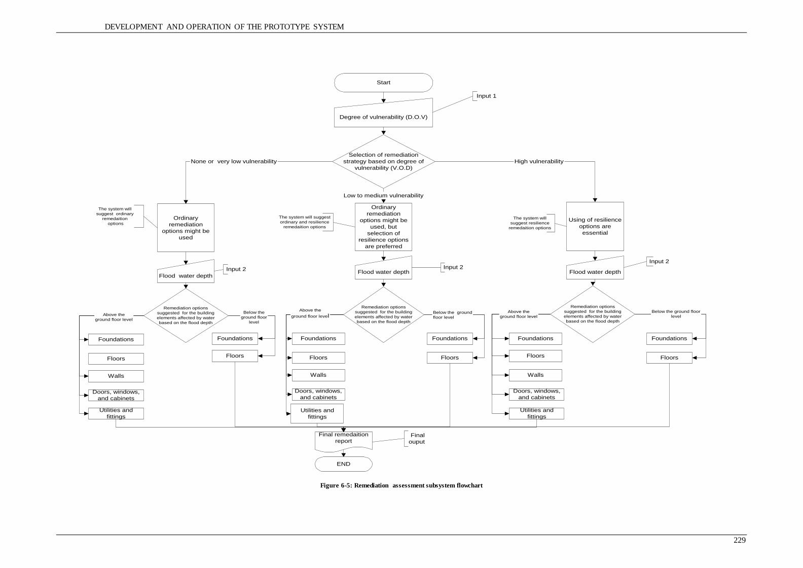
DEVELOPMENT AND OPERATION OF THE PROTOTYPE SYSTEM
229
Start
Degree of vulnerability (D.O.V)
Selection of remediation
strategy based on degree of
vulnerability (V.O.D)
Ordinary
remediation
options might be
used
Ordinary
remediation
options might be
used, but
selection of
resilience options
are preferred
Using of resilience
options are
essential
High vulnerability
Low to medium vulnerability
None or very low vulnerability
The system will
suggest ordinary
remedaition
options
The system will suggest
ordinary and resilience
remedaition options
The system will
suggest resilience
remedaition options
Input 1
Flood water depthFlood water depthFlood water depth
Remediation options
suggested for the building
elements affected by water
based on the flood depth
Input 2Input 2Input 2
Remediation options
suggested for the building
elements affected by water
based on the flood depth
Remediation options
suggested for the building
elements affected by water
based on the flood depth
Foundations
Floors
Foundations
Floors
Walls
Doors, windows,
and cabinets
Utilities and
fittings
Foundations
Floors
Foundations
Floors
Walls
Doors, windows,
and cabinets
Utilities and
fittings
Foundations
Floors
Walls
Doors, windows,
and cabinets
Utilities and
fittings
Foundations
Floors
Below the ground floor
levelAbove the
ground floor levelBelow the ground
floor level
Above the ground
floor levelBelow the
ground floor
level
Above the
ground floor levelAbove the
ground floor level
Final remedaition
report
END
Final
ouput
Figure 6-5: Remediation assessment subsystem flowchart
DEVELOPMENT AND OPERATION OF THE PROTOTYPE SYSTEM
230
6.2.3.2.3 The remediation options selection subsystem
The main idea of this subsystem is based on two assumptions: first, the fact that, when
the foundation moves, cracks will appear in the superstructure as a result of these
movements, and there will be signs of foundation movements; and second, there is the
assumption based on the fact that, after the flood, the damage caused by the flood to the
building foundations will be either significant owing to clay soil or subsidence due to
loose soil, saturation soils, or soil erosion.
The system starts with a diagnosis of the cracks due to foundation movement, and
thereby suggests remediation options. The system then recommends continuous and
detailed monitoring in order to avoid costly remediation options, such as underpinning
in the early stages. Underpinning is only suggested if the situation becomes worse.
The diagnosis and remediation options suggested by the system are based on the
technical manuals and reports, data sheets of some companies specialised in this field,
and own experience. The operation flowchart of the foundation damage assessment
subsystem is shown in Figure 6.6
6.3 OPERATION OF THE PROTOTYPE SYSTEM
6.3.1 SYSTEM REQUIREMENTS
This system will run on any Windows operating system which is able to support the .net
framework (i.e. Windows XP, Windows 7.0, Windows server 2003, etc.), although the
DEVELOPMENT AND OPERATION OF THE PROTOTYPE SYSTEM
231
system will require a minimal disk space of 50MB to be installed and operated
smoothly.
6.3.2 USER REQUIREMENTS
The end users of the prototype system will be mainly engineers working in the field of
flooded residential building management and repair, or building insurance in order to
evaluate how the building is vulnerable to damage by flooding. In addition, the system
can be used for training purposes since the system contains considerable information on
the flood damage assessment and remediation.
6.3.3 STARTING THE PROTOTYPE SYSTEM
The user starts by clicking the program icon which operates an executable file to run the
program. The database file used by the program should be held on the same drive as the
system operating file. The prototype system has a graphical user interface easy for use,
through which the user can easily navigate the entire prototype system with user-
friendly dialogue boxes and buttons which guide the user through the system, along
with helpful screens.
When the icon is clicked, the program starts and the main screen appears, as is shown in
Figure 6.7.
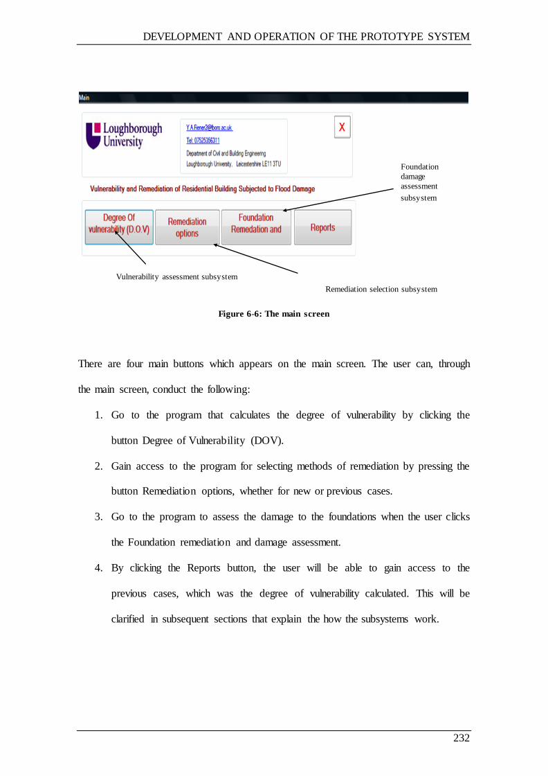
DEVELOPMENT AND OPERATION OF THE PROTOTYPE SYSTEM
232
Figure 6-6: The main screen
There are four main buttons which appears on the main screen. The user can, through
the main screen, conduct the following:
1. Go to the program that calculates the degree of vulnerability by clicking the
button Degree of Vulnerability (DOV).
2. Gain access to the program for selecting methods of remediation by pressing the
button Remediation options, whether for new or previous cases.
3. Go to the program to assess the damage to the foundations when the user clicks
the Foundation remediation and damage assessment.
4. By clicking the Reports button, the user will be able to gain access to the
previous cases, which was the degree of vulnerability calculated. This will be
clarified in subsequent sections that explain the how the subsystems work.
Foundation
damage
assessment
subsystem
Remediation selection subsystem
Vulnerability assessment subsystem
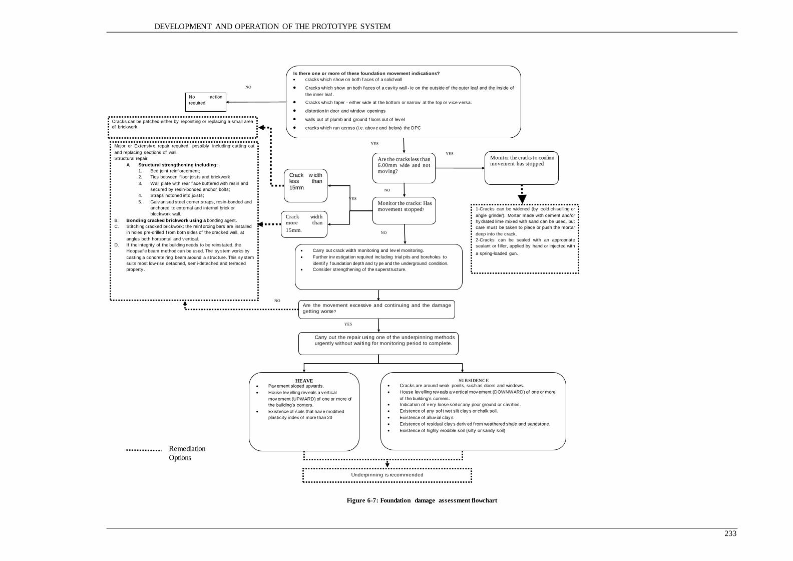
DEVELOPMENT AND OPERATION OF THE PROTOTYPE SYSTEM
233
Figure 6-7: Foundation damage assessment flowchart
Monitor the cracks: Has movement stopped?
Crack w idth less than
15mm.
Crack width more than
15mm.
Are the cracks less than 6.00mm wide and not moving?
Monitor the cracks to confirm movement has stopped
1-Cracks can be widened (by cold chiselling or
angle grinder). Mortar made with cement and/or
hy drated lime mixed with sand can be used, but
care must be taken to place or push the mortar
deep into the crack.
2-Cracks can be sealed with an appropriate
sealant or f iller, applied by hand or injected with
a spring-loaded gun.
YES
Cracks can be patched either by repointing or replacing a small area
of brickwork.
YES
NO
NO
Is there one or more of these foundation movement indications?
cracks which show on both f aces of a solid wall
Cracks which show on both f aces of a cav ity wall - ie on the outside of the outer leaf and the inside of
the inner leaf .
Cracks which taper - either wide at the bottom or narrow at the top or v ice v ersa.
distortion in door and window openings
walls out of plumb and ground f loors out of lev el
cracks which run across (i.e. abov e and below) the DPC
broken drains or disrupted serv ices
No action
required
YES
NO
Carry out crack width monitoring and lev el monitoring.
Further inv estigation required including trial pits and boreholes to
identif y f oundation depth and ty pe and the underground condition.
Consider strengthening of the superstructure.
Major or Extensiv e repair required, possibly including cutting out
and replacing sections of wall.
Structural repair:
A. Structural strengthening including:
1. Bed joint reinf orcement;
2. Ties between f loor joists and brickwork
3. Wall plate with rear f ace buttered with resin and
secured by resin-bonded anchor bolts;
4. Straps notched into joists;
5. Galv anised steel corner straps, resin-bonded and
anchored to external and internal brick or
blockwork wall.
B. Bonding cracked brickwork using a bonding agent.
C. Stitching cracked brickwork: the reinf orcing bars are installed
in holes pre-drilled f rom both sides of the cracked wall, at
angles both horizontal and v ertical.
D. If the integrity of the building needs to be reinstated, the
Hoopsaf e beam method can be used. The sy stem works by
casting a concrete ring beam around a structure. This sy stem
suits most low-rise detached, semi-detached and terraced
property .
Are the movement excessive and continuing and the damage
getting worse?
YES
HEAVE Pav ement sloped upwards.
House lev elling rev eals a v ertical
mov ement (UPWARD) of one or more of
the building’s corners.
Existence of soils that hav e modif ied
plasticity index of more than 20
SUBSIDENCE Cracks are around weak points, such as doors and windows.
House lev elling rev eals a v ertical mov ement (DOWNWARD) of one or more
of the building’s corners.
Indication of v ery loose soil or any poor ground or cav ities.
Existence of any sof t wet silt clay s or chalk soil.
Existence of alluv ial clay s
Existence of residual clay s deriv ed f rom weathered shale and sandstone.
Existence of highly erodible soil (silty or sandy soil)
Carry out the repair using one of the underpinning methods
urgently without waiting for monitoring period to complete.
NO
Underpinning is recommended
Remediation
Options
DEVELOPMENT AND OPERATION OF THE PROTOTYPE SYSTEM
234
6.3.3.1 Degree of vulnerability assessment subsystem
6.3.3.1.1 Vulnerability assessment input data sheet
In order to assess the degree of vulnerability, the user needs to input information
concerning the case to be assessed through the use of a data entry form. The data entry
form is similar to the input screen, which facilitates the entry of the information directly
without any modification, thereby leading to easier use of the program and thus saves
time as well as making it possible to enter information directly when the user is located
on-site. The data entry form contains a set of questions to be answered by the user (YES
or NO) depending on the circumstances of the case being assessed, the information that
has been collected, and the building survey. The data entry sheet for vulnerability
assessment is shown in Appendix C.
6.3.3.1.2 Operating the degree of vulnerability assessment subsystem
When the user clicks the degree of vulnerability button, a new screen will appear, as
illustrated in Figure 6.8. Using this screen, the user can calculate the degree of
vulnerability. At the top of the screen, the user able to enter the case number or
reference, as well as notes or comments using two text boxes provided known as Case
and Notes, whilst the date are entered automatically by the system.
In order to calculate the degree of vulnerability, the user starts by answering a set of
questions by selecting Yes or No using the selection button (Radio buttons) next to each
of these questions based on the information collected using the data collection sheet for
each case to be assessed. Finally, the degree of vulnerability can be calculated by
clicking the Test the Degree of Vulnerability (DOV) button at the bottom of the screen.
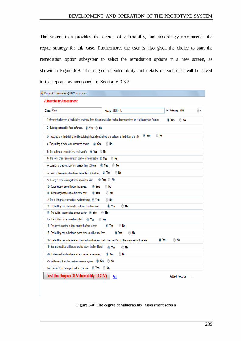
DEVELOPMENT AND OPERATION OF THE PROTOTYPE SYSTEM
235
The system then provides the degree of vulnerability, and accordingly recommends the
repair strategy for this case. Furthermore, the user is also given the choice to start the
remediation option subsystem to select the remediation options in a new screen, as
shown in Figure 6.9. The degree of vulnerability and details of each case will be saved
in the reports, as mentioned in Section 6.3.3.2.
Figure 6-8: The degree of vulnerability assessment screen

DEVELOPMENT AND OPERATION OF THE PROTOTYPE SYSTEM
236
Figure 6-9: The output screen of the degree of vulnerability assessment
6.3.3.2 Reports
Information relating to the degree of vulnerability is stored in the data using a Microsoft
Access database for all cases. The user is able to access this information and use it at
any time by clicking the Reports button provided on the main screen, which opens a
new screen, allowing the user to navigate the stored cases. The reports screen is shown
in Figure 6.10.
Assessed Degree of
vulnerability (in this case
High)
The recommended
repair strategy based
on the degree of
vulnerability
To start the remediation
selection subsystem

DEVELOPMENT AND OPERATION OF THE PROTOTYPE SYSTEM
237
When the screen is displayed, all the cases which have been assessed will be exhibited
in the form of tables, and through this screen, the user can review only those cases that
have been assessed as having low, medium or high vulnerability, by clicking the Low,
Medium or High button respectively. In addition, the user can view the evaluations of
all cases by clicking the All button. These buttons are located at the top right of the
screen. The user can also search for a particular case by entering a keyword in the
search box rectangle located on the top left of the screen, and then clicking the Search
button. There are also buttons for moving between pages in order to facilitate the search.
Reports can be printed, stored or exported, and earlier reports stored and displayed.
Figure 6-10: The reports screen
DEVELOPMENT AND OPERATION OF THE PROTOTYPE SYSTEM
238
6.3.3.3 Remediation options subsystem
6.3.3.3.1 Building survey data sheet
The user needs to survey the damaged building and collect information in order to
determine the information required to take advantage of the system, where the user
needs to know the depth of flooding, as well as the parts of the building which have
been damaged and therefore need maintenance. In addition, the type of construction,
and the materials used can be determined. This information needs to be collected
through a building survey, as well as through documents and drawings for the damaged
building. A building survey data sheet is provided in Appendix C.
6.3.3.3.2 Operating the remediation options subsystem
The remediation option subsystem provides options for the repair of different building
elements which are damaged by flooding. The idea of the system is that the general
repair strategy (either resilient or ordinary) is selected based on the degree of
vulnerability calculated by the degree vulnerability subsystem, and the system then
displays the damaged elements based on the depth of the flood. The repair options are
displayed for each element, with subcategories based on the type of construction or
material. For example, under the building element (Floors), there will be a number of
different types and construction of floors, such as sheet vinyl floors, quarry tiles floors,
solid concrete floors, etc.
The subsystem demonstrates the repair options applicable in each case (there might be
more than one option); this gives the user the opportunity to discuss matters with the
owner before making a decision—particularly in the case of resilient options where the

DEVELOPMENT AND OPERATION OF THE PROTOTYPE SYSTEM
239
owner would have to pay any extra costs above the insurance value, or negotiate with an
insurance company based on an insurance policy. There are also other reasons, as
mentioned in Section 6.2.3.3.3.
When the user clicks the Remediation option button, a new screen will appear which
allows the user to start selecting the remediation option for the new case or the previous
cases which are listed in the screen, as shown in Figure 6.11.
The user can navigate the previous cases assessed and then press the Select Cast button
to start viewing the remediation options available for this case. The other option is
where the user is able to create new case to assess and select the remediation options by
clicking the button Create New Case.
If the user selects to start viewing the remediation options available for one of the listed
case by clicking the Select Case button, at which point a new screen will appear similar
to that shown in Figure 6.9, where the user can start viewing the remediation options
available for this case upon clicking the Start button. When the user select to start a new
case by clicking the Create New Case button, then the degree of vulnerability
assessment screen will appear similar to that shown in Figure 6.8.

DEVELOPMENT AND OPERATION OF THE PROTOTYPE SYSTEM
240
Figure 6-11: The screen displayed when the user clicks the remediation option button
When the user clicks the Start button to view the remediation options available as in the
screen shown in Figure 6.12, a new screen will appear containing two buttons labelled
Flood Depth Below the Ground Floor Level, and Flood Depth Above the Ground Floor
Level, where the user is able to click one of these based on the case studied, as shown in
Figure 6.13.
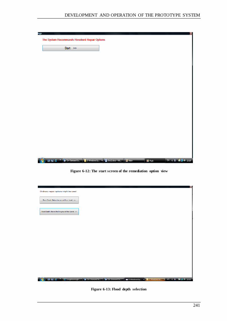
DEVELOPMENT AND OPERATION OF THE PROTOTYPE SYSTEM
241
Figure 6-12: The start screen of the remediation option view
Figure 6-13: Flood depth selection

DEVELOPMENT AND OPERATION OF THE PROTOTYPE SYSTEM
242
Based on the user selection, only the building elements damaged in this case will be
shown. The elements will be shown in the form of buttons representing the building
elements, as shown in Figure 6.14. If there are any subcategories under this element,
these will be shown in the form of buttons, as shown in Figure 6.15, which show the
subcategories under the element Floors.
Figure 6-14: Building elements selection screen
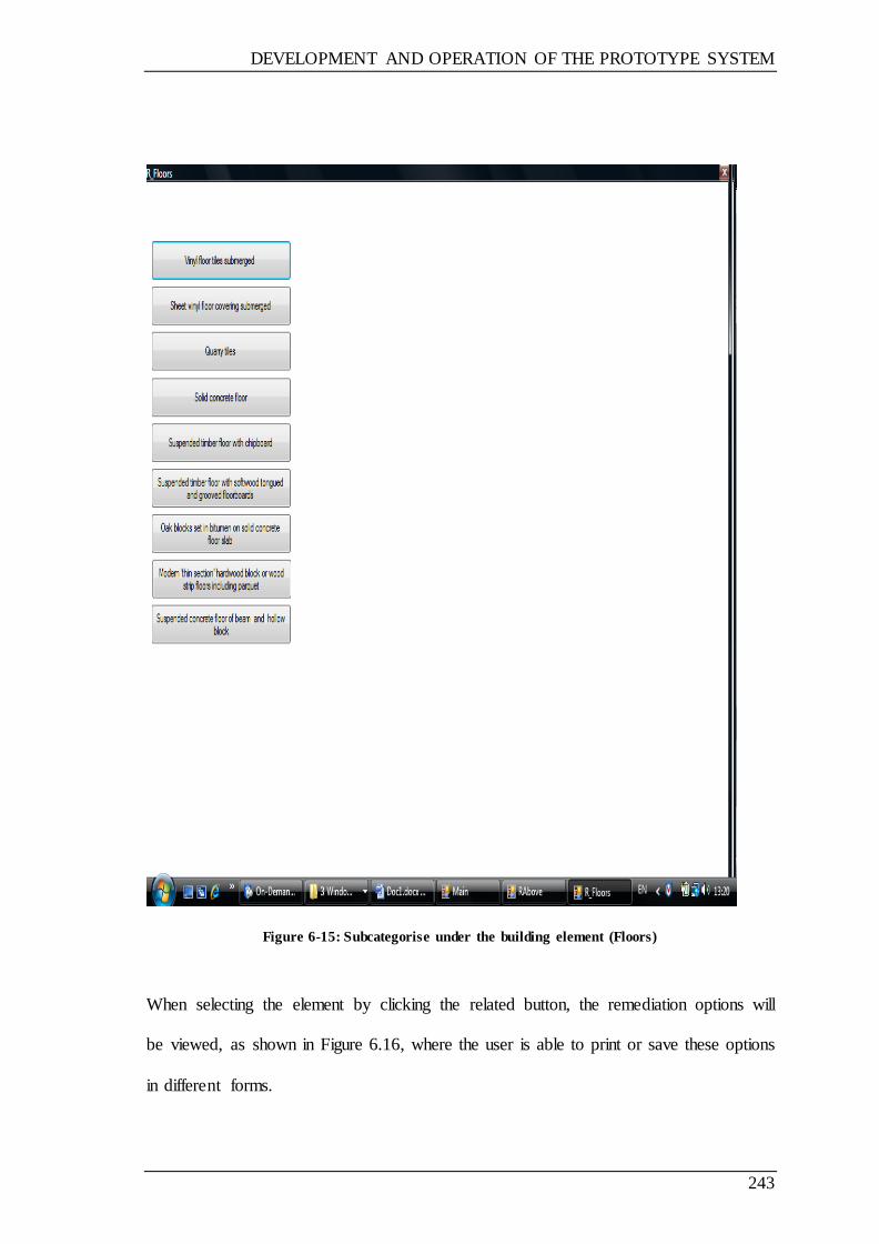
DEVELOPMENT AND OPERATION OF THE PROTOTYPE SYSTEM
243
Figure 6-15: Subcategorise under the building element (Floors)
When selecting the element by clicking the related button, the remediation options will
be viewed, as shown in Figure 6.16, where the user is able to print or save these options
in different forms.

DEVELOPMENT AND OPERATION OF THE PROTOTYPE SYSTEM
244
Figure 6-16: Example of the remediation viewed in case of concrete floor
6.3.3.4 Foundation damage assessment and remediation subsystem
When the user click the foundation damage assessment and remediation button in the
main menu of the prototype system, the system will started with a list of questions the
indicated the foundation movement and the user is required to choose either Yes or No
by clicking on of the button s provided as shown in Figure 6.17.

DEVELOPMENT AND OPERATION OF THE PROTOTYPE SYSTEM
245
Figure 6-17: The start screen of the foundation damage assessment and remediation subsystem
The subsystem based on a number of dialogue boxes and the reply of the user for
different circumstances for each individual case. The subsystem following the flowchart
procedure given in Figure 6.6. The subsystem interact with user in different ways
depends on the user response, in some case, giving inquiries where the user needs to
answer a question, as given in Figure 6.17.
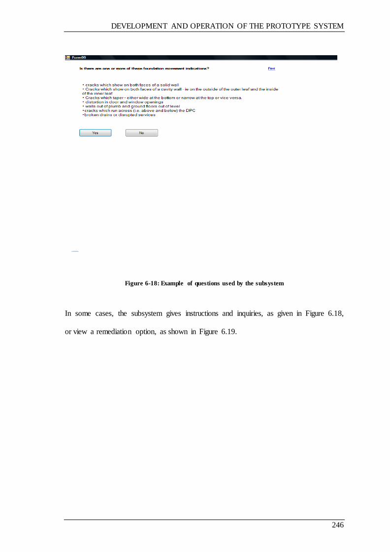
DEVELOPMENT AND OPERATION OF THE PROTOTYPE SYSTEM
246
Figure 6-18: Example of questions used by the subsystem
In some cases, the subsystem gives instructions and inquiries, as given in Figure 6.18,
or view a remediation option, as shown in Figure 6.19.

DEVELOPMENT AND OPERATION OF THE PROTOTYPE SYSTEM
247
Figure 6-19: Example of instruction and inquiry used by the system
Figure 6-20: Example of remediation options viewed by the subsystem
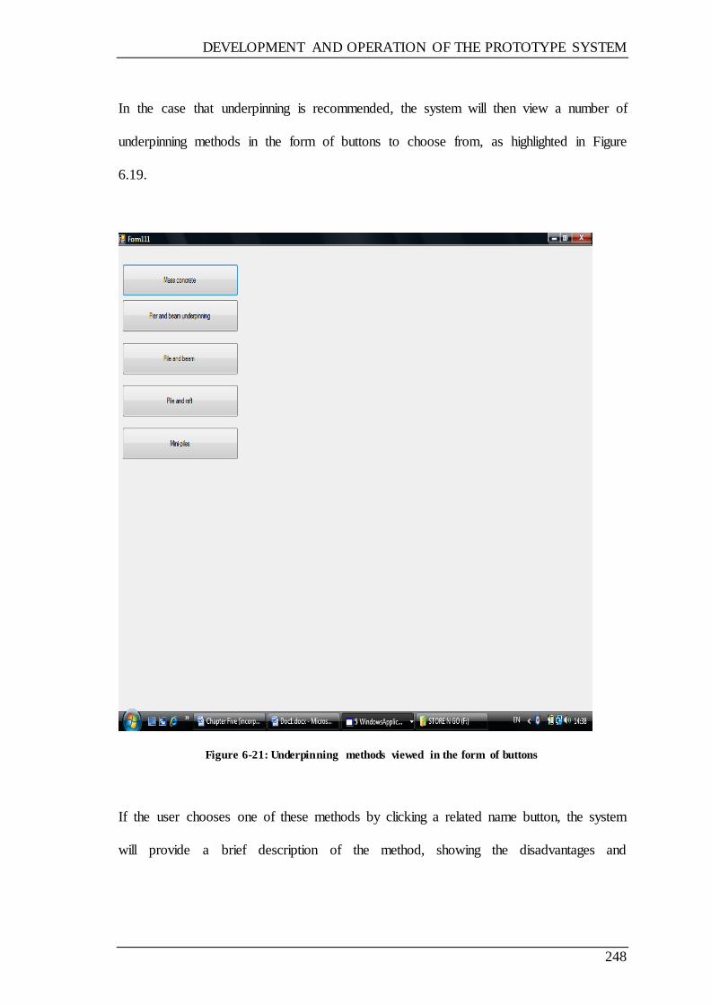
DEVELOPMENT AND OPERATION OF THE PROTOTYPE SYSTEM
248
In the case that underpinning is recommended, the system will then view a number of
underpinning methods in the form of buttons to choose from, as highlighted in Figure
6.19.
Figure 6-21: Underpinning methods viewed in the form of buttons
If the user chooses one of these methods by clicking a related name button, the system
will provide a brief description of the method, showing the disadvantages and
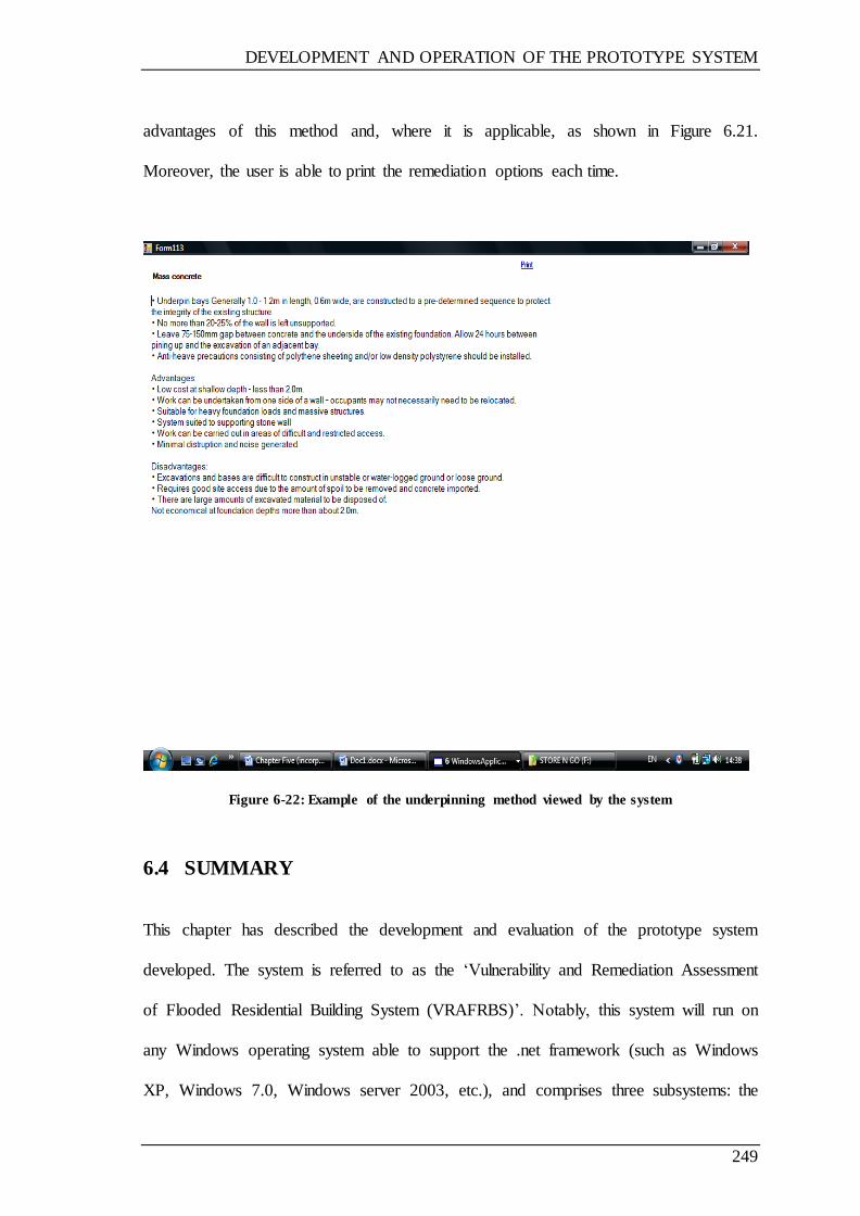
DEVELOPMENT AND OPERATION OF THE PROTOTYPE SYSTEM
249
advantages of this method and, where it is applicable, as shown in Figure 6.21.
Moreover, the user is able to print the remediation options each time.
Figure 6-22: Example of the underpinning method viewed by the system
6.4 SUMMARY
This chapter has described the development and evaluation of the prototype system
developed. The system is referred to as the ‗Vulnerability and Remediation Assessment
of Flooded Residential Building System (VRAFRBS)‘. Notably, this system will run on
any Windows operating system able to support the .net framework (such as Windows
XP, Windows 7.0, Windows server 2003, etc.), and comprises three subsystems: the

DEVELOPMENT AND OPERATION OF THE PROTOTYPE SYSTEM
250
Degree of vulnerability assessment, Remediation options, and Foundation damage
assessment prototype system evaluation. The user can calculate the degree of
vulnerability, which indicates the building‘s vulnerability to damage through flooding,
selecting remediation option based on the damaged building element and the degree of
vulnerability. Moreover, the user can assess the damage caused to the building
foundations and accordingly recommend repair options based on damage caused and
building foundation type. The system comprises user-friendly screen and easy-to-use
navigation through the use of vb.net and database.
The next chapter will discuss the evaluation of the system.
EVALUATION OF THE PROTOTYPE SYSTEM
251
CHAPTER 7 EVALUATION OF THE PROTOTYPE
SYSTEM
7.1 INTRODUCTION
The validation of a system or prototype is commonly viewed as being the foundation of
a validity assessment in the context of knowledge base systems. In this regard, a number
of knowledge base systems are a combination of software and framework. Moreover, it
is important to emphasise that the general process commonly implemented during the
validation of traditional programmes cannot be applied when seeking to conduct
knowledge base system validation.
This chapter describes the evaluation of the prototype system, and includes the aim and
the objectives of the evaluation, methodology, results and discussions for the overall
evaluation process. Moreover, the chapter concludes by providing a summary.
7.2 EVALUATION AIM AND OBJECTIVES
The overall evaluation was concerned with establishing the overall functionality and
usability of the final prototype system. In order to achieve this goal, the particular
objectives of the evaluation were:
To assess the performance of this prototype system in general;
To determine the extent of applicability of the system to use in assessment of
vulnerability of residential buildings to flood damage and their remediation;
To assess the effect of interaction on the user with the prototype system; and

EVALUATION OF THE PROTOTYPE SYSTEM
252
To obtain observations and suggestions on improving the status of the prototype
of the system.
7.3 EVALUATION METHODOLOGY
During the course of this study, an assessment has been carried out throughout
numerous different phases of the development of the prototype. During each of these
stages, data gathered was considered, and all aspects of the system were evaluated and
validating through interviews and discussions, such as with professionals attending
relevant workshops. In this regard, it can be stated that validation is a critical phase of
the evaluation, which is concerned with the overall performance of the system and the
level of accuracy. With this in mind, it is accurate to state that the system has been put
through a number of different changes and amendments.
Moreover, it is noteworthy to recognise that each time a researcher or professional in
this field made a suggestion concerning the system‘s improvements, these were taken
into account. Furthermore, upon completion of the prototype, professionals were
provided with the opportunity to review the system and give their feedback, with
researchers and experts in the field making various suggestions, which were
subsequently used in order to provide final improvements to the systems. With this
taken into consideration, the following section will discuss the evaluation approach
implemented in order to satisfy the overall study‘s aims and objectives, as highlighted at
the beginning of this paper.
EVALUATION OF THE PROTOTYPE SYSTEM
253
7.3.1 EVALUATION APPROACH
The evaluation was carried out following the creation of the prototype, and involved
experts from industry, academic experts, and group of experts from environment
Agency (EA). The British Damage Management Association (BDMA) were asked to
recommend one of the companies approved by them and working in the field of flood
building damage management. Accordingly, one of the recommended companies was
chosen, and a number of branches were then contacted in order to arrange for the
evaluation process. Moreover, two academic experts (from civil engineering
department, Loughborough university) working in the field of risk and vulnerability
assessment were involved in the evaluation of the prototype system. The final group
comprised a number of experts working in the field of risk assessment and flood
damage management from the Environment Agency (EA).
The research adopted both single and focus groups with a questionnaire technique in the
evaluation process. The focus group was adopted as the participants were then provided
with the opportunity to discuss and give appropriate feedback concerning the prototype
during the evaluation process. The questionnaire technique was adopted to measure the
usability of prototype system.
The prototype was demonstrated in relation to each single expert, with the exception of
the EA, in which case the prototype was demonstrated to a group of experts at the same
time at the Birmingham branch. The demonstration began with a presentation of the
prototype system background, and an explanation of how the system works and the
relation between each system components. Subsequently, every participant was allowed
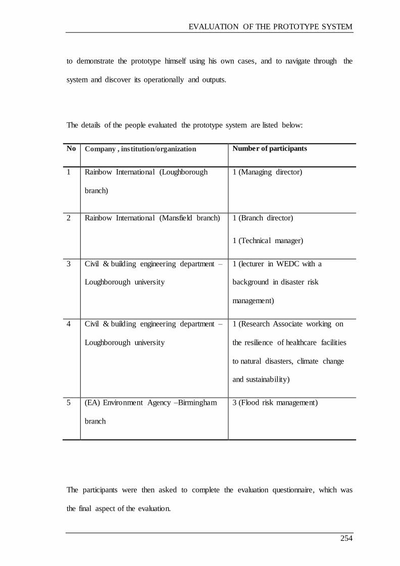
EVALUATION OF THE PROTOTYPE SYSTEM
254
to demonstrate the prototype himself using his own cases, and to navigate through the
system and discover its operationally and outputs.
The details of the people evaluated the prototype system are listed below:
No Company , institution/organization Number of participants
1 Rainbow International (Loughborough
branch)
1 (Managing director)
2 Rainbow International (Mansfield branch) 1 (Branch director)
1 (Technical manager)
3 Civil & building engineering department –
Loughborough university
1 (lecturer in WEDC with a
background in disaster risk
management)
4 Civil & building engineering department –
Loughborough university
1 (Research Associate working on
the resilience of healthcare facilities
to natural disasters, climate change
and sustainability)
5 (EA) Environment Agency –Birmingham
branch
3 (Flood risk management)
The participants were then asked to complete the evaluation questionnaire, which was
the final aspect of the evaluation.
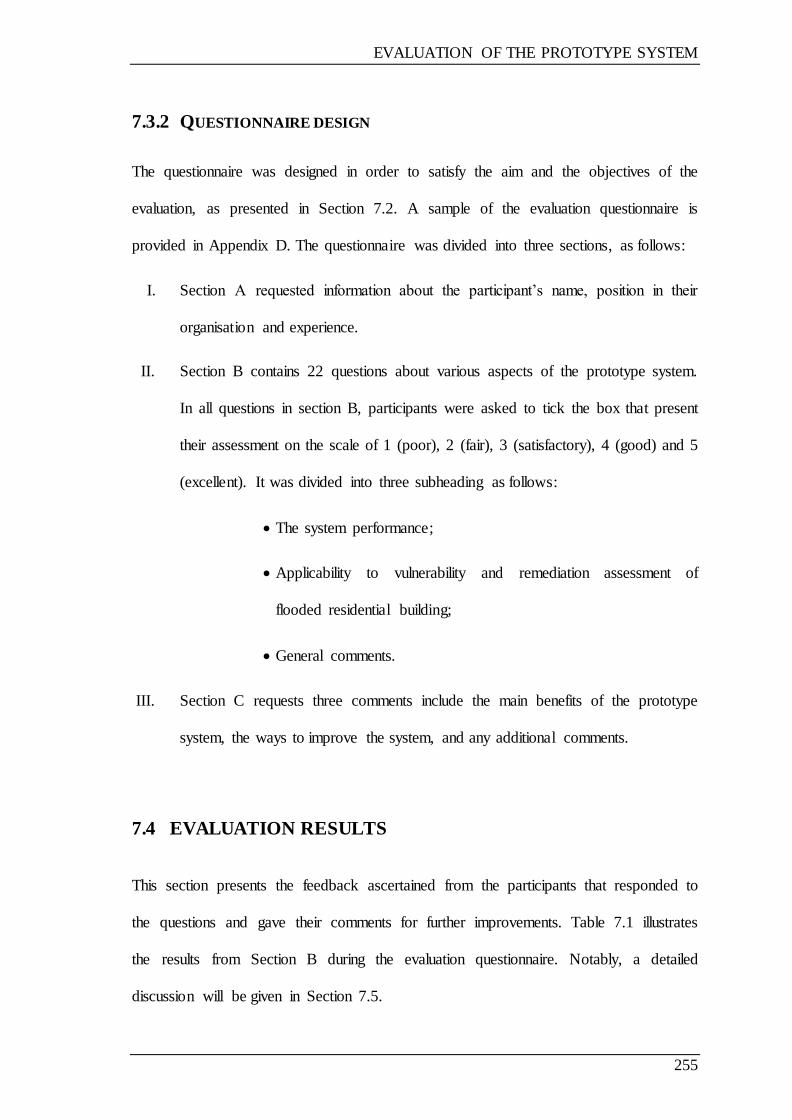
EVALUATION OF THE PROTOTYPE SYSTEM
255
7.3.2 QUESTIONNAIRE DESIGN
The questionnaire was designed in order to satisfy the aim and the objectives of the
evaluation, as presented in Section 7.2. A sample of the evaluation questionnaire is
provided in Appendix D. The questionnaire was divided into three sections, as follows:
I. Section A requested information about the participant‘s name, position in their
organisation and experience.
II. Section B contains 22 questions about various aspects of the prototype system.
In all questions in section B, participants were asked to tick the box that present
their assessment on the scale of 1 (poor), 2 (fair), 3 (satisfactory), 4 (good) and 5
(excellent). It was divided into three subheading as follows:
The system performance;
Applicability to vulnerability and remediation assessment of
flooded residential building;
General comments.
III. Section C requests three comments include the main benefits of the prototype
system, the ways to improve the system, and any additional comments.
7.4 EVALUATION RESULTS
This section presents the feedback ascertained from the participants that responded to
the questions and gave their comments for further improvements. Table 7.1 illustrates
the results from Section B during the evaluation questionnaire. Notably, a detailed
discussion will be given in Section 7.5.

EVALUATION OF THE PROTOTYPE SYSTEM
256
Table 7.2 presents the comments relating to the benefits of the prototype system, as well
as suggestions on how to improve the system from Section C in the questionnaire,
which were provided by evaluators.
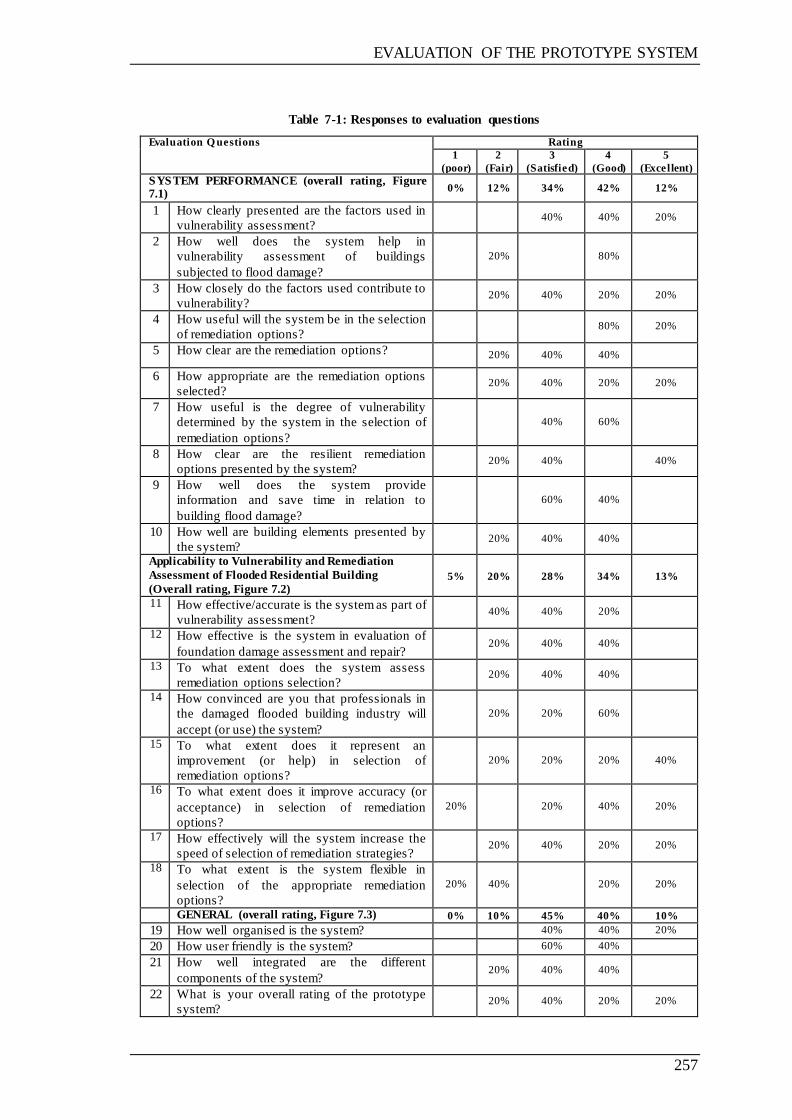
EVALUATION OF THE PROTOTYPE SYSTEM
257
Table 7-1: Responses to evaluation questions
Evaluation Q uestions Rating
1
(poor)
2
(Fair)
3
(Satisfied)
4
(Good)
5
(Excellent)
SYSTEM PERFORMANCE (overall rating, Figure 7.1)
0% 12% 34% 42% 12%
1 How clearly presented are the factors used in
vulnerability assessment? 40% 40% 20%
2 How well does the system help in
vulnerability assessment of buildings
subjected to flood damage?
20% 80%
3 How closely do the factors used contribute to
vulnerability? 20% 40% 20% 20%
4 How useful will the system be in the selection
of remediation options? 80% 20%
5 How clear are the remediation options?
20% 40% 40%
6 How appropriate are the remediation options
selected? 20% 40% 20% 20%
7 How useful is the degree of vulnerability
determined by the system in the selection of
remediation options?
40% 60%
8 How clear are the resilient remediation
options presented by the system? 20% 40% 40%
9 How well does the system provide
information and save time in relation to
building flood damage?
60% 40%
10 How well are building elements presented by
the system? 20% 40% 40%
Applicability to Vulnerability and Remediation
Assessment of Flooded Residential Building
(Overall rating, Figure 7.2)
5%
20%
28%
34%
13%
11 How effective/accurate is the system as part of
vulnerability assessment? 40% 40% 20%
12 How effective is the system in evaluation of
foundation damage assessment and repair? 20% 40% 40%
13 To what extent does the system assess
remediation options selection? 20% 40% 40%
14 How convinced are you that professionals in
the damaged flooded building industry will
accept (or use) the system?
20% 20% 60%
15 To what extent does it represent an
improvement (or help) in selection of
remediation options?
20% 20% 20% 40%
16 To what extent does it improve accuracy (or
acceptance) in selection of remediation
options?
20% 20% 40% 20%
17 How effectively will the system increase the
speed of selection of remediation strategies? 20% 40% 20% 20%
18 To what extent is the system flexible in
selection of the appropriate remediation
options?
20% 40% 20% 20%
GENERAL (overall rating, Figure 7.3) 0% 10% 45% 40% 10%
19 How well organised is the system? 40% 40% 20%
20 How user friendly is the system? 60% 40%
21 How well integrated are the different
components of the system? 20% 40% 40%
22 What is your overall rating of the prototype
system? 20% 40% 20% 20%
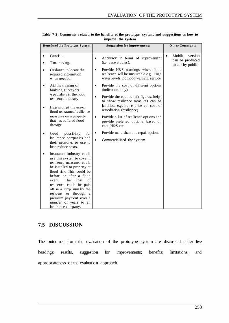
EVALUATION OF THE PROTOTYPE SYSTEM
258
Table 7-2: Comments related to the benefits of the prototype system, and suggestions on how to
improve the system
Benefits of the Prototype System Suggestion for Improvements O ther Comments
Concise.
Time saving.
Guidance to locate the
required information
when needed.
Aid the training of
building surveyors
/specialists in the flood
resilience industry
Help prompt the use of
flood resistance/resilience
measures on a property
that has suffered flood
damage
Good possibility for
insurance companies and
their networks to use to
help reduce costs.
Insurance industry could
use this system to cover if
resilience measures could
be installed to property at
flood risk. This could be
before or after a flood
event. The cost of
resilience could be paid
off in a lump sum by the
resident or through a
premium payment over a
number of years to an
insurance company.
Accuracy in terms of improvement
(i.e. case studies).
Provide H&S warnings where flood
resilience will be unsuitable e.g. High
water levels, no flood warning service
Provide the cost of different options
(indication only)
Provide the cost benefit figures, helps
to show resilience measures can be
justified. e.g. home price vs. cost of
remediation (resilience).
Provide a list of resilience options and
provide preferred options, based on
cost, H&S etc.
Provide more than one repair option.
Commercialised the system.
Mobile version
can be produced
to use by public
7.5 DISCUSSION
The outcomes from the evaluation of the prototype system are discussed under five
headings: results, suggestion for improvements; benefits; limitations; and
appropriateness of the evaluation approach.
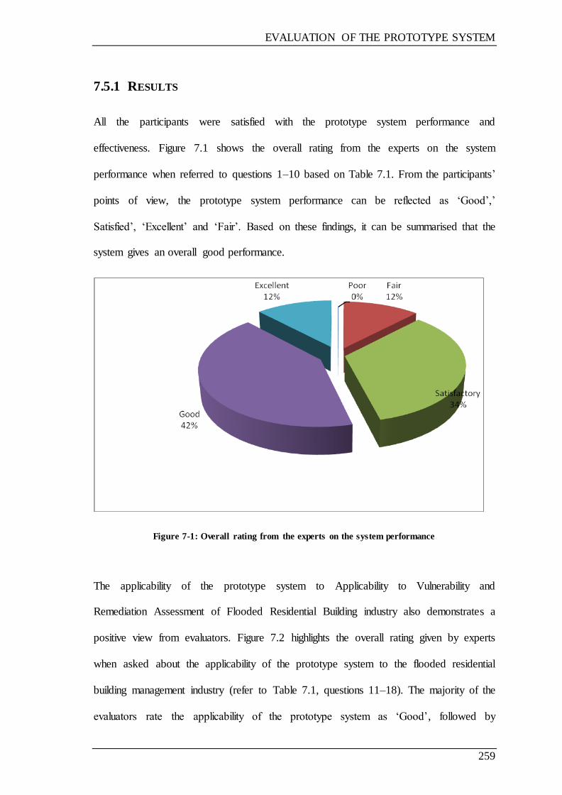
EVALUATION OF THE PROTOTYPE SYSTEM
259
7.5.1 RESULTS
All the participants were satisfied with the prototype system performance and
effectiveness. Figure 7.1 shows the overall rating from the experts on the system
performance when referred to questions 1–10 based on Table 7.1. From the participants‘
points of view, the prototype system performance can be reflected as ‗Good‘,‘
Satisfied‘, ‗Excellent‘ and ‗Fair‘. Based on these findings, it can be summarised that the
system gives an overall good performance.
Figure 7-1: Overall rating from the experts on the system performance
The applicability of the prototype system to Applicability to Vulnerability and
Remediation Assessment of Flooded Residential Building industry also demonstrates a
positive view from evaluators. Figure 7.2 highlights the overall rating given by experts
when asked about the applicability of the prototype system to the flooded residential
building management industry (refer to Table 7.1, questions 11–18). The majority of the
evaluators rate the applicability of the prototype system as ‗Good‘, followed by
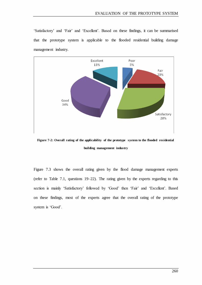
EVALUATION OF THE PROTOTYPE SYSTEM
260
‗Satisfactory‘ and ‗Fair‘ and ‗Excellent‘. Based on these findings, it can be summarised
that the prototype system is applicable to the flooded residential building damage
management industry.
Figure 7-2: Overall rating of the applicability of the prototype system to the flooded residential
building management industry
Figure 7.3 shows the overall rating given by the flood damage management experts
(refer to Table 7.1, questions 19–22). The rating given by the experts regarding to this
section is mainly ‗Satisfactory‘ followed by ‗Good‘ then ‗Fair‘ and ‗Excellent‘. Based
on these findings, most of the experts agree that the overall rating of the prototype
system is ‗Good‘.
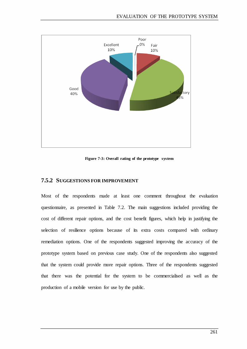
EVALUATION OF THE PROTOTYPE SYSTEM
261
Figure 7-3: Overall rating of the prototype system
7.5.2 SUGGESTIONS FOR IMPROVEMENT
Most of the respondents made at least one comment throughout the evaluation
questionnaire, as presented in Table 7.2. The main suggestions included providing the
cost of different repair options, and the cost benefit figures, which help in justifying the
selection of resilience options because of its extra costs compared with ordinary
remediation options. One of the respondents suggested improving the accuracy of the
prototype system based on previous case study. One of the respondents also suggested
that the system could provide more repair options. Three of the respondents suggested
that there was the potential for the system to be commercialised as well as the
production of a mobile version for use by the public.
EVALUATION OF THE PROTOTYPE SYSTEM
262
7.5.3 BENEFITS OF THE PROTOTYPE
Through the evaluation, the respondents identified several practical benefits of the
prototype system, including:
Concise: the system summarise the evaluation of vulnerability and selection of
remediation options in short and concise form.
Time-saving: the system can help in providing of repair strategies by demonstrating
a repair options and flood damage scenarios.
Guidance to locate the required information when needed: the system provides all
the information required in organised form.
Aid the training of building surveyors/specialists in the flood resilience industry
Help prompt the use of flood resistance/resilience measures on a property which has
suffered flood damage.
Good possibility for insurance companies and their networks to use in order to assist
with reducing costs.
Insurance industry could use this system to establish if resilience measures could be
installed to properties at flood risk. This could be before or after a flood event. The
cost of resilience could be paid off in a lump sum by the resident, or otherwise
through a premium payment over a number of years to an insurance company.
7.6 SUMMARY
This chapter has provided a summary of the prototype system evaluation. The research
adopted questionnaire techniques in evaluating the prototype system. The results from

EVALUATION OF THE PROTOTYPE SYSTEM
263
the evaluation show that the prototype system illustrates good performance, and is
suitable for use in the residential building flood damaged building industry. Finally, the
comments and suggestion from the evaluation have been used to refine the prototype
system. The next chapter presents the conclusion and recommendations of the research.
CONCLUSION AND RECOMMENDATIONS
264
CHAPTER 8 CONCLUSION AND
RECOMMENDATIONS
8.1 INTRODUCTION
This chapter concludes the research project, which has resulted in the development of a
knowledge base system named ‗Vulnerability and Remediation Assessment of Flooded
Residential Buildings‘ (VRAFRB). This chapter summarises all the findings of the
research, and is followed by the benefits and limitations of the prototype system. It also
presents the conclusions, and makes recommendations for further research.
8.2 SUMMARY
The reason for conducting this particular study is the necessity to provide an improved
tool for the management of residential flooding, with the potential to conduct an
assessment to determine the vulnerability of properties, as well as recommending
solutions. In order to fulfil such a requirement, the study pursued a fundamental goal,
which was to create a systematic method of facilitating the selection of remediation
options in direct consideration of the risk assessment. This goal was broken down into a
number of different objectives:
to review the exposure of residential buildings to the risk of flood damage,
especially in the UK
to review recent developments in research into the vulnerability assessment and
remediation of residential buildings subjected to flooding
CONCLUSION AND RECOMMENDATIONS
265
to develop a method to assess the vulnerability of residential buildings subjected
to flood damage
to undertake detailed case studies with a view to establishing current industry
practice, identifying opportunities for improvement and establishing end-user
requirements
to develop a framework and functional specification for an intelligent approach
to the vulnerability assessment and remediation of residential buildings subject
to flood damage
to implement and evaluate a prototype system based on the functional
specification developed above and on test cases from industry.
Various research methodologies and strategies have been adopted in order to achieve
the defined objectives of the research. The initial strategies included an extensive
literature review, participation at workshops and seminars to interact with other
researchers and professionals in similar research areas, and discussions with
practitioners in the flood damage industry. The knowledge acquisition process was
undertaken following this initial stage in order to capture the knowledge relating to
vulnerability assessment and management of flood damage to residential buildings. The
methods applied include a survey using a postal questionnaire and interviews, and data-
gathering through documents related to the topic. Following the capturing of
knowledge, the rapid prototyping methodology was applied during the process of
developing the prototype system. The prototype was evaluated after the development
process in order to verify, validate and improve it. Chapter 2 described the basic
concepts and principles of the research methodology.

CONCLUSION AND RECOMMENDATIONS
266
Definitions of vulnerability, an explanation of vulnerability and hazard assessment with
some examples, and the method developed to calculate the vulnerability of residential
buildings to flood damage were all presented in Chapter 3. On the basis of the literature
review of vulnerability assessment methods, it was highlighted that a comprehensive
methodology for risk assessment of buildings subject to flooding has been missing.
With the aforementioned in mind, a method of estimating the vulnerability of buildings
to flood damage was developed, based on various key factors—particularly the
susceptibility of the building elements to damage by floodwater, as well as the
susceptibility of the entire building to flooding (e.g. as a result of its geographical
location), leaving aside other considerations (e.g. health risks). This means that only
physical damage to the building‘s elements has been taken into account. The model
developed calculates the degree of vulnerability, which indicates how vulnerable the
building is to damage when subjected to flooding. The degree of vulnerability was also
used to determine the use of either ordinary repair options (in the case of low
vulnerability) or resilience options (in the case of high vulnerability). The calculation of
vulnerability is one of the subsystems of the prototype system that is being developed.
The review of flood damage management and knowledge base systems was presented in
Chapter 4, and was broken down into two parts. During this process, it became clear
that, over recent years, the risks and consequences of flood events have become a reality
for an increasing number of properties. The degree of damage caused by a flood when
in contact with building elements is dependent mainly on flood depth and material type,
as well as other factors relating to the location of the building and its condition prior to
CONCLUSION AND RECOMMENDATIONS
267
flooding. Flooding can damage buildings in many ways, although it is recognised that
the most common flood damage consists of:
direct damage at the time of flooding, caused by high speed flows and waves,
erosion, or debris carried by the floodwater
damage caused to building materials by water contact during the flood period
and sometimes after.
Essentially, the building elements that are in contact with water during a flood event
might be damaged and need repair or replacement. There are also various other issues to
be taken into account in the context of flood damage management, including property
owners‘ dissatisfaction with the performance of a particular contractor and/or insurance
company, the costs associated with insurance cover, which are not related to risk, the
lack of fairness (different standards applied by different companies), and the funding of
flood repairs by those not at risk via higher premiums. These issues indicate that there is
a fundamental need to improve the flood management of residential buildings, for
example through establishing reinstatement repair strategies with not too much
variation, increasing the satisfaction of homeowners, allowing better underwriting
decisions, promoting fairness, and reducing time and the costs of repair by introducing
resilience repair options.
The literature review reveals that there is no system that can be used to evaluate the
vulnerability of residential buildings to flood damage, or to assess vulnerability in terms
of the selection of remediation options. The selection of remediation options and risk
assessment are based on the contractor‘s or building surveyor‘s judgment, with the
CONCLUSION AND RECOMMENDATIONS
268
result that two similar houses in the same area may have a different insurance premium
or different repair costs if they are flooded. In view of this, the owners of the damaged
buildings can benefit from using the knowledge base system to assess the vulnerability
of such buildings in regard to flood damage, and in the selection of remediation options;
this saves time and helps to standardise repair strategies and therefore provide fair
insurance to the resident.
The knowledge acquisition process is an important part of the development of the
knowledge base system for the Vulnerability and Remediation Assessment of Flooded
Residential Buildings. Knowledge was acquired from different sources relating to
vulnerability assessment and flood damage management with the aim of developing a
prototype system, as presented in Chapter 5. The knowledge acquisition process
involved capturing and gaining knowledge from different sources to develop a
vulnerability assessment model including factors which contribute to flood damage, to
assign weighting or rating to the factors, and finally to produce the vulnerability
assessment model. Accordingly, the required information was arranged in the form of
tables or charts, which could be used in the selection of remediation options to develop
the remediation options selection subsystem and foundation damage assessment
subsystem as parts of the prototype system.
An industry survey was carried out by postal questionnaire to study the factors
considered to affect flood damage. The aim was to help in the weighting and rating of
factors when developing the vulnerability assessment model, and thereby to reveal any
other factors that might not have been considered. The knowledge relating to the
CONCLUSION AND RECOMMENDATIONS
269
remediation options and their selection was collected by postal survey and the review of
related documents. Knowledge was also captured during attendance at workshops
relating to the topic, with contributions from experts and professionals, and the
information gained was accordingly developed and validated in each case through
discussion with experts attending the workshops.
The proposed prototype system was named ‗Vulnerability and Remediation Assessment
of Flooded Residential Buildings System‘ (VRAFRBS). The development and
operation of VRAFRBS was described in Chapter 6.
The prototype knowledge base system comprises three subsystems: degree of
vulnerability assessment, remediation options, and foundation damage assessment. The
vulnerability assessment subsystem is used to calculate the degree of vulnerability,
which will be then used by the remediation options subsystem to select a remediation
strategy. The vulnerability assessment subsystem can be used to calculate the degree of
vulnerability of the building in relation to flood damage—even if it is not flooded. The
remediation options subsystem recommends two strategy options: either ordinary
remediation options, in cases where vulnerability is low, or resilience remediation
options, in cases where vulnerability is high. The foundation damage assessment
subsystem works alone, and is used to assess the damage caused by flood to the
building foundation and to recommend a repair option based on damage caused and
foundation type.

CONCLUSION AND RECOMMENDATIONS
270
The evaluation of the prototype system after it had been developed was described in
Chapter 7. The research adopted a questionnaire technique in evaluating the prototype
system. The evaluators chose to approach different people related to different flood
damage issues, including people from the industry, researchers, and experts in risk and
vulnerability assessment. The evaluation confirms that, even though some
improvements were required to make the system more effective, it does provide many
benefits, demonstrates good performance, and is highly applicable for use in the flood-
damaged buildings industry.
As can be seen from the above, the objectives of the research project have generally
been achieved.
8.3 BENEFITS OF THE PROTOTYPE SYSTEM
The prototype system offers many benefits to engineers and others involved in
management and damage assessment of flooded residential buildings.
It provides a clear and structural framework which assists in the vulnerability
and remediation assessment of flooded residential buildings. The repair
strategies are recommended on the basis of the degree of vulnerability
calculated, whether ordinary or resilience options are recommended.
It saves time by providing in an organised manner all the information required to
develop a repair strategy quickly. The system user is able to discuss the different
options available with the client and display them more easily.
The system can work as a guide to locate the required information when needed.
CONCLUSION AND RECOMMENDATIONS
271
The system can be used by insurance companies to assess the risk for different
residential buildings and to provide an appropriate basis for insurance cost
estimation. All the respondents emphasised this in their discussion during the
evaluation of the system.
The system can aid the training of building surveyors in the flood resilience
industry.
The system offers a good possibility for insurance companies and their networks
to reduce costs through its utilisation.
The system can help in the standardisation of repair strategies and insurance
premium calculation for residential buildings.
The system can help to provide repair strategies through demonstrating repair
options and flood damage scenarios.
The system provides all the information required in an organised format.
The system can help to prompt the use of flood resistance/resilience measures on
a property which in areas of high flood risk.
The insurance industry could use this system to cover if resilience measures
could be installed to property at risk of flooding. This could be either before or
after a flood event. The cost of resilience could be paid off in a lump sum by the
resident, or otherwise through a premium payment over a number of years to an
insurance company.
8.4 LIMITATIONS OF THE PROTOTYPE SYTEM
The limitations of the prototype system include the following:

CONCLUSION AND RECOMMENDATIONS
272
The prototype system is designed for use in the case of residential buildings
specifically in the UK.
The vulnerability calculated represents the damage to building elements due to
flooding and the cost of repair.
8.5 CONCLUSIONS
Several conclusions can be drawn from the research. These include:
More homes will be at risk of flooding because of the impacts of climate change,
which means that more attention needs to be directed to the area of flood risk
management research, including the management of flood-damaged residential
buildings. It is difficult to prevent floods from occurring, but the effects of
floods can be managed in order to reduce risks and the costs of repair.
There are some major issues related to the existing management of flood
damaged buildings that require attention to improve this industry: these include
an increased need for professional advice to both individuals and developers on
designing for floods, the need for definitive guidance on repairing flood-
damaged buildings to minimize variations in subsequent repair and
reinstatement works, and the inclusion of flood resilience measures in the repair
of flood-damaged buildings to reduce the cost of repair in the future in high
flood risk areas.
Defining vulnerability can help us decide how to reduce it. Assessing the
vulnerability of buildings in flood-prone areas is a key issue when evaluating the

CONCLUSION AND RECOMMENDATIONS
273
risk induced by flood events; nevertheless, a comprehensive methodology for
risk assessment of buildings subject to flooding is still missing.
Vulnerability of residential buildings can be assessed on the basis of the factors
that are considered to contribute to vulnerability to flood damage.
In this research a method of assessing the vulnerability of residential buildings
to flood damage was developed, based on the factors that are believed to
contribute to flood damage to buildings. The developed model is based on key
factors—in particular, the susceptibility of the building elements to damage by
floodwater, as well as the susceptibility of the entire building to flooding (e.g. as
a result of its geographical location). These factors were then ranked and given
numerical weight based on their importance, and these weightings were then
used to calculate the degree of vulnerability (as a numerical value) which was
then converted to a descriptive rating. The model is based on the weighting and
rating of factors which are known to contribute to flood damage, and a simple
mathematical equation has been used to calculate the degree of vulnerability,
were then incorporated into a piece of software written by the author and
accordingly used as a part (subsystem) of the entire developed knowledge base
system.
This research reveals that the knowledge relating to flood damage management
is written in books and technical reports, as well as guides and journal papers,
and codes of practice. This knowledge is either too general or too specialised for
practical purposes, and the task of searching through many documents for
information relating to a particular situation is time-consuming. So there is a
need for an organised and concise system to evaluate the vulnerability of
residential buildings subjected to flood damage, which should comprise all
CONCLUSION AND RECOMMENDATIONS
274
information relating to repair methods and the procedure of remediation of
buildings damaged by flood, and lead to standardised and speedy repair of
flooded buildings. Such a system should also help in establishing the basis for
the risk assessment and repair process of flooded residential buildings. In
addition, the system should also include resilience options as another repair
option which could reduce the time and cost of repairs in case the building is
flooded in the future.
The knowledge base system proposed in this research has the aim of achieving
the following objectives:
o to assess and evaluate the vulnerability of buildings to flood damage, and
to consider factors contributing to building flood damage
o to assist in the selection of repair methods and procedures to be followed
when dealing with flooded buildings, based on the degree of
vulnerability to flood damage
o to aid in the selection of suitable flood damage reduction options by
introducing resilience options as these will reduce the cost of future
damage repair. The resilience remediation options are only
recommended when the vulnerability of buildings to flood damage is
high.
The repair methods suggested by the knowledge base system are mainly based
on the standard repair methods available in documents such as repair manuals
and technical reports.
The overall evaluation of the proposed knowledge base system was concerned
with establishing the overall functionality and usability of the final prototype
CONCLUSION AND RECOMMENDATIONS
275
system. In order to achieve this goal, the particular objectives of the evaluation
were:
o to assess the performance of this prototype system in general
o to determine the extent of applicability of the system for use in the
assessment of vulnerability of residential buildings to flood damage and
their remediation
o to obtain observations and suggestions on improving the status of the
prototype of the system.
The proposed system could help in standardizing the repair and management of
damage to flooded residential buildings.
8.6 RECOMMENDATIONS FOR FURTHER RESEARCH
This research project has revealed a number of areas for further research and
development, including:
1. Further improvements to the prototype system, with respect to:
adding more repair options to the options suggested by the system,
based on different real cases
updating the resilience repair options on the basis of new materials
and new techniques
improving the user interface and adding more facilities and
functions.
CONCLUSION AND RECOMMENDATIONS
276
2. Further research should be carried out to improve the accuracy of the
degree of vulnerability assessment on the basis of real data considering
sub-factors and previous flood damage cases.
3. The system should be integrated with other systems which are applied to
calculate the cost, to enable the system to estimate the cost of repair and
make comparisons between different repair strategies based on their cost.
4. From observations during the research project, it seems that the literature
available on damage to building elements caused by flooding and its
relations with other factors (flood characteristics, building
characteristics) is limited; therefore, more research should be carried out
in order to investigate these relations.
5. More research is also needed to investigate the damage caused by
flooding to different building foundations, since the literature available is
very limited.
6. Further research should be carried out with the aim of improving the
prototype system, which can be effectively used as a teaching and
training tool.
7. The research has explored in detail the management of flood damage to
residential buildings, and gathered various types of information; this can
be used as a basis for further research in relation to the vulnerability of
residential buildings to flood damage and the selection of remediation
options.
CONCLUSION AND RECOMMENDATIONS
277
8.7 CLOSING REMARKS
The development system will contribute to improving the management and repair of
buildings damaged by flood; the system will not completely replace human experts, but
will nevertheless help stakeholders in this industry. This research provides a small
contribution to the improvement of the management and repair of flood-damaged
residential buildings.

REFERENCES
278
REFERENCES
ABI, 2002. ABI Statement of Principles on the provision of flooding insurance.
London: Association of British Insurers
ABI, 2003. Assessment of the cost and effect on future claims of installing flood
damage resistant measures. London: Association of British Insurers.
ABI, 2005. Revisiting the partnership: five years on from autumn 2000
Anniversary Report. London: An of British Insurers
ABI, 2006. Flood resilient homes. What homeowners can do to reduce flood
damage. London: Association of British Insurers.
ABI, 2007. Summer Floods 2007: Learning the Lessons. London: Association of
British Insurers.
ABI, 2008. Climate Adaptation - Guidance on Insurance Issues for New
Developments. London: Association of British Insurers.
ABI, 2010. Fighting Flood Risk Together. London: Association of British
Insurers.
ABI, 2010a. ABI News Release. London: Association of British Insurers Available at:
http://www.abi.org.uk/Media/Releases/2010/11/Cumbria_floods_one_year_on__ABI_highlights_key_role_played_by_insurers_in_helping_the_region_recover
_.aspx [Accessed 25 December 2010].
ABI/NFF, 2005. Repairing your home or business after a flood: how to limit
damage and disruption in the future. London: Association of British Insurers and the National Flood Forum.
ABI/NFF, 2006. Repairing your home or business after a flood - how to limit
damage and disruption in the future. London: Association of British Insurers and the National Flood Forum.
Adeli, H., ed., 1988. Knowledge base systems in Construction and Structural
Engineering. London and New York: Chapman and Hall
Alexander, ED, 2005. Vulnerability to landslides. In: T. Glade T ,M.G. Anderson, M.J. Crozier, eds. Landslide risk assessment. Chichester: John Wiley pp. 175–198.
Anderson, R., Crabtree, B.F., Steele, D.J. and McDaniel, R.R., 2005. Case Study Research: The View From Complexity Science. Qualitative Health; Research,
15(5), pp. 669-685.

REFERENCES
279
Anumba, C. J., Scott, D. and Webster, C.A.G., 1995. A Knowledge-Based
Advisory System for Housing Subsidence Cases, Developments. In: B. H. V. Topping, ed. Artificial Intelligence for Civil and Structural Engineering.
Edinburgh: Civil-Comp Press, 1995, pp. 169-175.
Arain, F.M. and Low, S.P., 2006. A knowledge-based system as a decision
making tool for effective management of variations and design improvement: leveraging on information technology applications. In: International Journal of IT in Architecture, Engineering and Construction (ITAEC + ITCon), Special
Issue Architectural informatics, 11(1): pp. 373―392.
Atkinson, M.F., 2004. Structural foundations manual for low-rise buildings (2nd
edition). Oxford: Taylor & Francis.
Badiru, A.B., 1992. Knowledge base systems Applications in Engineering and
Manufacturing. Englewood Cliffs: Prentice-Hall.
Birkmann, J., 2007. Risk and vulnerability indicators at different scales:
Applicability, usefulness and policy implications. Environmental Hazards, 7, pp. 20-31.
Bowker, P., 2007. Flood resistance and resilience solutions an R&D scoping study. London: Department for Environment, Food and Rural Affairs.
Breach, M., 2009. Dissertation writing for engineers and scientists. Harlow:
Prentice Hall.
British Standards Institute, 2005. PAS 64. Professional water damage mitigation
and initial restoration of domestic dwellings.
Broadbent, C., 2004. Improving the flood resistance of domestic property.
Structural Survey, 22(2), pp. 79–83.
Brooks, N., 2003. Vulnerability, risk and adaptation: a conceptual framework.
Working Paper 38. Norwich: Tyndall Centre for Climate Change Research, University of East Anglia,. Available at: www.tyndall.ac.uk.
Buckle, P.; Marsh, G.; Smale, S., 2000. New Approaches to Assessing Vulnerability and resilience. Australian Journal of Emergency Management,
Winter 2000. Pp8-14.
Building Research Establishment, 2006. Repairing flooded buildings: An
industry guide to investigation and repair. Watford: BRE Press.
Cannon, T., 1993. A hazard need not a disaster make: vulnerability and the causes of ‗natural‘ disaster. In: P.A. Merriman and C.W.A. Browitt, eds. Natural
Hazards. London: Thomas Telford.
Cardona, O.D., 2004. The need for rethinking the concepts of vulnerability and
risk from a holistic perspective: a necessary review and criticism for effective
REFERENCES
280
risk management. In: G. Bankoff, G. Frerks, D. Hilhorst, eds. Mapping
Vulnerability: Disasters, Development and People. London: Earthscan Publishers.
Cardona, O.D., 2006. A system of indicators for disaster risk management in the America‘. In: J. Birkmann ed. Measuring Vulnerability to Hazards of Natural
Origin: Towards Disaster Resilient Societies. Tokyo: United Nations University Press.
Castellanos, V., Albiter, A., Hernandez, P., and Barrera, G., 2011. Failure
analysis knowledge base system for onshore pipelines. Part – I: Structured database and knowledge acquisition. Knowledge base systems with Applications.
Available at: doi:10.1016/j.eswa.2011.02.153.
Chau, K.W., Albermani, F., 2005. A knowledge-based system for liquid
retaining structure design with black blackboard architecture. Building and Environment, 40(1), pp. 73-81.
Chen L. X., Yin, K. L., Dai, Y. X.,2011. Building vulnerability evaluation in
landslide deformation phase. Journal of mountain science, Vol. 8 (2), pp. 286-295.
CIRIA, 2003a. Flood Resilience Improving the Flood Resistance of Your Home
and Business, Advice Sheet 7: Flood Resilient Drains and Sewers. London:
CIRIA.
CIRIA, 2003b. Flood Resilience. Improving the Flood Resistance of Your Home
and Business, Advice Sheet 4: Flood Resilient Walls. London: CIRIA.
CIRIA, 2003c. Improving the Flood Resistance of Your Home: Advice Sheets 1–8. London: CIRIA.
CIRIA, 2004a. Standards for the Repair of Buildings Following Flooding. CIRIA Report C623. London: CIRIA.
CIRIA, 2004b. Development & Flood Risk – Guidance for the Construction Industry. CIRIA Report C624. London: CIRIA.
CIRIA, 2007. Improving the flood resistance of your home - advice sheets 1-7. London: CIRIA.
Clark, G.E., Moser, S.C., Ratick, S.J., Dow, K., Meyer, W., Emani, S., Jin, W., Kasperson, R.E., Kasperson, J.E.X. and Schwarz, H., 1998. Assessing the
vulnerability of coastal communities to extreme storms: the case of Revere, MA, USA. Mitigation and Adaptation Strategies for Global Change, Vol. 3, pp. 59-82.
Cobby, D., Morris S., Parkes, A. and Robinson, V., 2009. Groundwater flood risk management: Advances towards meeting the requirements of the EU floods
directive. Journal of Flood Risk Management 2 (2), pp. 111-119.
REFERENCES
281
Cohen, L., Manion, L. and Morrison, K., 2000. Research Methods in Education.
(Fifth edition). London and New York: Routledge.
Cornford, T. and Smithson, S., 2006. Project research in information systems: a
student's guide (2nd Ed.). Basingstoke: Palgrave Macmillan.
Creswell, JW., 1995. Research design: Qualitative and quantitative approaches.
Thousand Oaks CA: Sage.
Crichton, D., 2003. Flood Risk and Insurance in England and Wales: Are there
lessons to be learned from Scotland? London: Benfield Grieg Hazard Research Centre, Department of Earth Sciences, University College London,.
Cutter, S. L., Boruff, B. J. and Shirley, W. L., 2003. Social Vulnerability to Environmental Hazards, Social Science Quarterly, 84 (1), pp. 242-261.
DCLG, 2010. Guidance and standards for drying flood damaged buildings. Signposting current guidance: BD 2760. London: DCLG Publications.
DCLG/Environment Agency, 2007. Improving the Flood Performance of New
Buildings: Flood Resilient Construction. London: CLG Publications.
De Brito, J., Branco, F.A., Ibanez, M., 1994. A knowledge based concrete bridge
inspection system, Concrete International, Vol.16, pp. 59-63.
DEFRA, 2001. National appraisal of assets at risk from flooding and coastal
erosion. London: Department for Environment Food and Rural Affairs.
DEFRA, 2008. Developing the evidence base for flood resistance and resilience.
R&D Technical Report FD2607/TR1. London: Department for Environment, Food and Rural Affairs.
DEFRA, 2008. Resilience Grants Pilot Projects. London: Department for Environment, Food and Rural Affairs.
DEFRA, 2010. Amendment to the Building Act to Allow Building Regulations to Require Flood Resilient Repair. Final Report, January 2010. Available at:
http://archive.defra.gov.uk/environment/flooding/documents/policy/fwmb/fwmiabuildingreg.pdf [downloaded on April 2010].
Department for Environment Food and Rural Affairs, 2008. Consultation on
policy options for promoting property-level flood protection and resilience.
[Online]. [Cited 25th April 2009] Available from:
<http://www.defra.gov.uk/corporate/consult/floodprotection/consultation-
document.pdf>.
Dickinson, P. R. and Thornton, N., 2004. Cracking and Building Movement.
Coventry: RICS Business Services Ltd.
REFERENCES
282
Dilley, M., Chen, R.S., Deichmann, U., Lerner-Lam, A., Arnold, M., 2005.
Natural Disaster Hotspots. A Global Risk Analysis. Washington DC: The World Bank, Hazard Management Unit.
Dodov, Dr. B., 2008. Assessing Flood Risk: A Hydrological Overview of the July UK Floods. AIR Worldwide Corporation.
Downing, T.E., 1993. Concepts of vulnerability to famine and applications in Subsaharan Africa. In: G. Bohle, T.E. Downing, J.O. Field and F.O. Ibrahim,
eds. Coping with Vulnerability and Criticality: Case Studies on Food Insecure Peoples and Places, Saarbruecken and Fort Lauderdale, FL: Breitenbach, pp. 205-59.
Driscoll R M C, Skinner H, 2007. Subsidence damage to domestic buildings: a guide to good technical practice, BRE Trust. Bracknell: IHS BRE Press.
DTLR, 2002. Preparing for Floods - Interim Guidance for Improving the Flood Resistance of Domestic and Small Business Properties. London: TSO.
Durkin, J., 1994. Knowledge base systems design and development. Englewood Cliffs, NJ: Prentice Hall.
Dyer, M., 2004. Performance of flood embankments in England and Wales.
Proceedings of the Institution of Civil Engineers Water Management , Volume
157, Issue 4, pp. 177-186.
EA, 2006. Making Space for Water. Groundwater flooding records collation,
monitoring and risk assessment (reference HA5). Extended Report (Chalk Aquifers). Bristol: Environment Agency.
EA, 2008. Environment Agency Online Flood risk mapping website. Available at: http://www.environmentagency.gov.uk/subjects/flood.
EA, 2009. Flooding in England/Wales: A National Assessment Of Flood Risk . Bristol: Environment Agency.
EA, 2011. UK industry should develop new technologies to flood-proof homes. Available at: http://www.environment-agency.gov.uk/news/116386.aspx. [Last accessed 10th April 2011].
Emberey, C.L., Milton, N.R., Berends, J.P.T.J., van Tooren, M.J.L., van der Elst, S.W.G. and Vermeulen, B., 2007. Application of Knowledge Engineering
Methodologies to Support Engineering Design Application Development in Aerospace. 7th AIAA Aviation Technology, Integration and Operations
Conference (ATIO). Belfast, Northern Ireland.Engineering Geology, 73(3-4), pp. 297-309.
Environment Agency, 2009a. Investing for the future: Flood and coastal risk
management in England. A long-term investment strategy. [Online]. [Cited 20th
REFERENCES
283
April 2010] Available from: http://publications.environment-
agency.gov.uk/pdf/GEHO0609BQDF-E-E.pdf.
Environment, Food and Rural Affairs Committee, 2008. Flooding, Fifth Report of Session 2007–08. Vol.1. Available at:
http://www.publications.parliament.uk/pa/cm200708/cmselect/cmenvfru/49/49.pdf.
Escarameia, M. Karanxha, A. and Tagg, A, 2006. Improving the flood resilience
of buildings through improved materials, methods and details. Report no. WP5C Final Report. London: Construction Industry Research and Information
Association (CIRIA).
Escarameia, M., Karanxha, A. and Tagg, A., 2007. Quantifying the flood
resilience properties of walls in typical UK dwellings. Building Services Engineering Research and Technology, August 2007 28: pp. 249-263.
Evans, E.P., Ashley, R., Hall, J.W., Penning-Rowsell, E.C., Saul, A., Sayers, P.B., Thorne,C.R., Watkinson, A.R., 2004. Foresight Future Flooding Scientific Summary, Volume 1: Future Risks and their Drivers. London: Office of Science
and Technology.
Farinha, F., Portela, E., Domingues, C. and Sousa, L., 2005. Knowledge-based
systems in civil engineering: Three case studies. Advances in Engineering Software, 36 (11-12), p. 729.
Fellows, R. and Liu, A., 2003. Research Methods for Construction. 2nd ed. Oxford: Blackwell Science Limited.
Fellows, R. and Liu, A., 2008. Research methods for construction. 3rd edition. Oxford: Wiley-Blackwell.
Fetterman, D., 1998. Ethnography step by step (2nd ed.). Thousand Oaks, CA: Sage.
Fiener, Y.A.F. and Ali, F., 1999. Application of hazard and risk maps for
highway and slopes management and maintenance. In: Yagi, Yamagani and Jiang, eds., Slope stability engineering. Rotterdam: Balkema. Pp. 1287-1290.
Fink, A., 2010. Conducting Research Literature Reviews. Thousand Oaks: Sage.
Flood Repairs Forum, 2006. A guide to the investigation and repair of flood
damage to housing and small business. Watford: BRE Press.
Fuchs, S., Heiss, K., Hubl, J., 2007. Towards an empirical vulnerability function
for use in debris flow risk assessment. Nat. Hazards Earth Syst. Sci., 7: pp. 495–506.
REFERENCES
284
Garvin, S., Reid, J. and Scott, M., 2005. Standards for the repair of buildings
following flooding. London: Construction Industry Research and Information (CIRIA).
Giarratano, J. C., 1998. Knowledge base systems: Principles and programming (3rd ed.). London: Brooks/Cole.
Giarratano. J., and Riley, G., 1998. Knowledge base systems: Principles and
Programming. Boston: PWS Publishing.
Gibson, W. and Brown, A., 2009. Working with qualitative data. London:
SAGE publications.
Glover, Peter, 2006. Building surveys. 6th ed. Oxford: Butterworth-
Heinemann/Elsevier.
Green, C. 2004. The evaluation of vulnerability to flooding. Disaster Prevention
and Management 13(4): pp. 323–329.
Green, C. H. and Suleman, M., 1987. Investment Appraisal for Urban Storm
Drainage Systems. Fourth International Conference on Urban Storm Drainage. pp.351-356.
Gwilliam, J., Fedeski, M., Lindley, S., Theuray, N. and Handley, J., 2006.
Methods for assessing risk from climate hazards in urban areas. Proc. ICE Municipal Engineer, 159, Dec. Issue ME4, pp. 245‐255.
Harris, D.J., 1995. Moisture beneath suspended timber floors. Structural Survey,
Vol. 13 Iss: 3, pp.11 – 15.
Hayes-Roth, F., Waterman, D.A., Lenat, D.B., 1983. Building Knowledge base
systems. Reading, MA, Addison-Wesley.
Hendy, P., 2006. Carlisle events—the victims’ perspective. Proceedings of Flood repair Network Workshop on Identification and Dissemination of Good
Practice. London: Thomas Telford. Available at: http://www.floodrepair.net/docs/paul_Flood_Repair_Net_PPT.ppt [accessed
10/03/2008].
Hiete, M. and Merz, M., 2009. An Indicator Framework to Assess the
Vulnerability of Industrial Sectors against Indirect Disaster Losses. Paper no. 131. Goteborg: ISCRAM.
Intergovernmental Panel on Climate Change (IPCC), 1992. Global Climate and
the Rising Challenge of the Sea. Response Strategies Working Group, Intergovernmental Panel on Climate Change, Geneva, Switzerland, p. 115.
International Council for Science, 2002. Resilience and Sustainable Development, Series on Science for Sustainable Development No 3, Paris:
International Council for Science.
REFERENCES
285
IPCC, 2001. Climate Change 2001: Impacts, Adaptation, and Vulnerability.
Contribution of Working Group II to the Third Assessment Report of the Intergovernmental Panel on Climate Change. Cambridge: Cambridge
University Press.
Ismail, N. , Ismail, A. and Atiq, R, 2009. An Overview of Knowledge base
systems in Pavement Management. European Journal of Scientific Research, 30(1), pp. 99-111.
Jacobs, 2007. Groundwater flooding records collation, monitoring and risk
assessment (reference HA5). Consolidated Report. Making Space for Water. Prepared for the Environment Agency.
John W. Creswell, 2003. Research Design. Qualitative, Quantitative and Mixed Methods Approaches, 2nd ed. London: SAGE publications.
Jonkman, S.N. and Vrijling, J.K., 2008. Loss of life due to floods. Journal of Flood Risk Management 1, pp. 43–56.
Kaetzel, L.J. and Clifton, J.R., 1995. Expert/Knowledge based systems for materials in the construction industry: state-of-the-art report. Materials and
Structures, 28,1995, pp. 160-174.
Kelman, I. and Spence, R., 2004. An overview of flood actions on buildings,
Engineering Geology, volume 73, issues 3-4, pp.297-309.
Kemp, R., 2007. Assessing the vulnerability of buildings. Disaster Prevention
and Management, Vol. 16 Iss: 4, pp. 611 – 618.
Kendal, S.L.; Creen, M., 2007. An introduction to knowledge engineering.
London: Springer.
Kron, W., 2005. Flood Risk = Hazard • Values • Vulnerability, Water
International, Vol.30 No 1, pp. 58 – 68.
Kunreuther, H. and Pauly, M., 2004. Neglecting disaster: Why don‘t people
insure against large losses?. Journal of Risk and Uncertainty 28: pp. 5–21.
Lamond, J., 2008. The impact of flooding on the value of residential property in
the UK. Unpublished PhD Thesis, University of Wolverhampton, Wolverhampton. Available from
http://wlv.openrepository.com/wlv/handle/2436/31427.
Lamond, J., Proverbs, D., and Antwi, A., 2007a. Measuring the impact of
flooding on UK house prices: A new framework for small sample problems. Property Management, 25(4): pp. 344-359.
Lamond, J., Proverbs, D., and Antwi, A., 2007b. The impact of flood insurance
on residential property prices: towards a new theoretical framework for the UK
REFERENCES
286
market. Journal of the Financial Management of Property and Construction,
12(3), pp. 129-137.
Law, D. & Longworth, G., 1987. Systems Development: Strategies and
Techniques. Manchester: NCC Publications.
le Polain de Waroux, O., 2011. Floods as Human Health Risks. Encyclopedia of
Environmental Health. Available at: doi:10.1016/B978-0-444-52272-6.00628-0
Lejk, M. and D. Deeks, 2002. Systems Analysis Techniques, Addison Wesley.
Lukasheh A.F., Droste, R.L. and Warith, M.A., 2001 Review of knowledge base system (ES), geographical information system (GIS), decision support system
(DSS) and their application in landfill design and management. Waste Manag Res 19: pp. 177–185.
Macdonald, D.M.J.; Bloomfield, J.P.; Hughes, A.G.; MacDonald, A.M.; Adams,
B. and McKenzie, A.A., 2008. Improving the understanding of the risk from groundwater flooding in the UK: FLOOD risk 2008, European Conference on
Flood Risk Management, Oxford, UK, 30 Sept - 2 Oct 2008. The Netherlands: CRC Press.
Manu, P., Phandey, R. and Proverbs, D,G., 2010. An investigation into the barriers towards making existing domestics properties more resilient to the effects of flooding: results of a case study. In: The Construction, Building and
Real Estate Research Conference of the Royal Institution of Chartered Surveyors, 2-3 September 2010, Dauphine Université, Paris. p.22.
McQueen, R.A., and Knussen, C., 2002. Research Methods for Social Science: A Practical Introduction. Harlow: Prentice Hall.
Messner F. and Meyer V., 2005, Flood damage, vulnerability and risk perception- challenges for flood damage research. UFZ-Diskussionspapier
13/2005, 24 S.
Messner, F., Penning-Rowsell, E., Green, C., Meyer, V., Tunstall, S. andVan der Veen, A., 2007. Evaluating flood damages: guidance and recommendations on
principles and methods. Wallingford, UK: FLOODsite Consortium.
Milton, N. R., 2007. Knowledge Acquisition in Practice: A Step-by-step Guide.
London: Springer.
Mujica L.E., Vehi J., Rodellar J. and Kolakowski P., 2005. A hybrid approach of
knowledge-based reasoning for structural assessment. Smart Materials and Structures, vol. 14, no. pp. 1554-1562.
Naoum, S. G., 2007. Dissertation research and writing for construction students. 2nd ed. Oxford: Butterworth-Heinemann.
REFERENCES
287
Naoum, S.G., 2004. Dissertation Research and Writing for Construction
Students. Oxford: Elsevier Butterworth-Heinemann.
National Audit Office, 2007. Environment Agency: Building and maintaining
river and coastal flood defences in England, report by the Comptroller and Auditor General, HC Session 528, 2006–07, London: HMSO.
Negnevitsky, M., 2005. Artificial Intelligence: a guide to intelligent systems. Essex, England: Pearson Education Limited.
Neuman, W. Lawrence., 2003. Social research methods: qualitative and quantitative approaches, 5th ed. Boston: Allyn and Bacon.
Nicholas, J., Holt, G.D. and Proverbs, D., 2001. Towards standardising the assessment of flood damaged properties in the UK. Structural Survey, Volume
19, Number 4, pp. 163–172.
Nicholas, J., Proverbs, D.G. and Holt, G.D., 2001. An Investigation Into Factors Influencing the Assessment Of UK Flood Damaged Properties. Proceedings of
the RICS COBRA Conference. Glasgow Caledonian University, 3-5 September, pp 660-669.
Nicholls, R.J. and R.J.T. Klein, 2000. Some thoughts on impacts and adaptation to climate change in coastal zones. In: A.C. de la Vega-Leinert, R.J. Nicholls, A.
Nasser Hassan and M. El-Raey, eds. Proceedings of the SURVAS Expert Workshop on African Vulnerability and Adaptation to Impacts of Accelerated Sea-Level Rise Cairo, Egypt, 5–8 November 2000, Flood Hazard Research
Centre, Middlesex University, Enfield, UK, pp. 9–17.
Oates, B. J., 2006. Researching Information Systems and Computing. London:
Sage Publications Ltd.
ODPM, 2003. Preparing for floods. Interim guidance for improving the flood
resistance of domestic and small business properties. 2003 Reprint. Wetherby: ODPM Publications Centre.
ODPM, 2003. Sustainable Communities: Building for the Future. London: TSO.
Office of Science and Technology (OST) (2004). Foresight. Future Flooding.
Executive Summary. Office of Science and Technology, London.
OFWAT, 2008. Service and delivery – performance of the water companies in
England and Wales. Available at: http://www.ofwat.gov.uk/regulating/reporting/rpt_los_2007-08.pdf.
Parker D.J., Green C.H., Thompson P.M., 1987. Urban flood protection
benefits: a project appraisal guide (The Red Manual). Aldershot, UK: Gower Technical Press.

REFERENCES
288
Peduzzi, P., 2006. The disaster risk index: overview of a quantitative approach.
In: J. Birkmann, ed., Measuring Vulnerability to Natural Hazards—Towards Disaster Resilient Societies. New York: United Nations University Press.
Penning-Rowsell E., Johnson C., Tunstall S., Tapsell S., Morris J., Chatterton J., Coker A., and Green C., 2003. The Benefits of flood and coastal defence:
techniques and data for 2003. Middlesex University: Flood Hazard Research Centre.
Pitt, M., 2008. The Pitt Review: Lessons learned from the 2007 floods. Cabinet
Office [internet]. Available at: http:// www.cabinetoffice.gov.uk/~/
Proverbs, D.G. and Soetanto, R., 2004. Flood Damaged Property: A Guide to
Repair. Blackwell Publishing.
Rhodes, D. A. and Proverbs, D., 2008. An investigation of the current state of
preparedness of the flood damage management sector in the UK: what lessons have been learnt? COBRA 2008, The construction and building research
conference of the Royal Institution of Chartered Surveyors (RICS), Dublin Institute of Technology, 4-5 September 2008.
Richardson, M. and Domingos, P., 2006. Markov logic networks. Machine Learning, 62, pp. 107–136.
RMS, 2001. UK river flood, risk assessment models. Risk Management
Solutions.
Robson, C., 2007. How to do a Research Project: A Guide for Undergraduate
Students, Oxford, UK; Madden, Mass: Blackwell Publishers
Rodriguez-Bachiller and Glasson, J., 2004. Knowledge base system and
Geographic information system for impact assessment . London, New York Taylor & Francis.
Samwinga, V and Proverbs, D., 2003. The repair of flood damaged property: a critical review of the needs of homeowners. In: D.J. Greenwood, ed., 19th
Annual ARCOM Conference, 3-5 September 2003, university of Brighton. Association of Researchers in Construction Management, Vol. 2, pp. 867-78.
Samwinga, V., Proverbs, D. and Homan, J., 2004. Exploring the experience of
UK homeowners in flood disasters. COBRA 2004 The international construction research conference of the Royal Institution of Chartered
Surveyors 7-8 September 2004.
Schmidtlein, M. C., Deutsch, R., Piegorsch, W. W. and. Cutter, S. L., 2008. A
Sensitivity Analysis of the Social Vulnerability Index, Risk Analysis 28 (4), pp. 1099-1114.
REFERENCES
289
Soetanto, R. and Proverbs, D.G., 2004. Impact of flood characteristics on
damage caused to UK domestic properties: the perceptions of building surveyors, Structural Survey, Vol. 22 Iss: 2, pp. 95 – 104.
Soetanto, R., Proverbs, D. and Nicholas, J., 2002. Assessment of Flood Damage to Domestic Properties: Surveyors' Perceptions of Flood Characteristics. In:
Cobra 2002. Proceedings of the RICS Foundation Construction and Building Research Conference. 2-6 September 2002, The Nottingham Trent University. pp. 154-168.
Soetanto, R., Proverbs, D., Lamond, J., Samwinga, V., 2008. Residential properties in England and Wales: an evaluation of repair strategies towards
attaining flood resilience. In: L.S. Bosher, ed., Hazards and the Built Environment: Attaining Built-in Resilience, London: Routledge, pp.124–49.
Somekh, B. and Lewin, C., eds., 2005. Research Methods in the Social Sciences. London: Sage Publications.
Sommerville, I., 2001. Software Engineering, 6th ed, Addison-Wesley.
Thomas, G.. 2009. How to do your research project: A guide for students in
education and applied social sciences. London: Sage Publications.
Tommelein, I. D., 1997. Knowledge base systems for civil engineers: Integration
issues. New Yor: ASCE.
Turban, E., Aronson, J. E. and Liang, T.P., 2005. Decision Support Systems and
Intelligent Systems, 7th edition. Pearson Education.
Turban, E., Aronson, J.E., 2001, Decision Support Systems and Intelligent
Systems Sixth Edition: Knowledge Management. Upper Saddle River: Prentice Hall.
Turban, E., Aronson, J.E., Liang, T.P. and Sharda, R., 2007. Decision Support
and Business Intelligence Systems, Upper Saddle River: Prentice Hall.
Turban, E., Leidner, D., McLean, E. and Wetherbe, J. 2008. Information
Technology for Management: Transforming Organizations in the Digital Economy, (6th edition), John Wiley & Sons, USA.
Tyagunov, S., Stempniewski, L., Grünthal, G., Wahlström, R., Zschau, J., 2004. Vulnerability and risk assessment for earthquake-prone cities. In: Proceedings of
the 13th World Conference on Earthquake Engineering, Vancouver, BC, Canada, 1-6 August, 2004.
UNDP, 2004. Reducing Disaster Risk: A Challenge for Development . New
York: United Nations Development Programme, Bureau for Crisis Prevention and Recovery.
REFERENCES
290
United Nations International Strategy on Disaster Reduction (UNISDR), 2009, ―UNISDR Terminology on Disaster Risk Reduction,‖ Available at:
http://www.unisdr.org/eng/terminology/terminology-2009-eng.html [ accessed 6
August 2011].
United Nations University, 2004. Two Billion People Vulnerable to Floods by
2050, News Release, June 13, 2004. Available at: http://www.unu.edu/news/ehs/floods.doc [accessed 20 March 2008].
Villagran de Leon, J.C., 2006. Vulnerability - A Conceptual and Methodological
Review, SOURCE -Publication Series of UNU-EHS, United Nations University.
Welbank, M. A., 1983. A Review of Knowledge Acquisition Techniques for
Knowledge base systems. Martlesham Heath, Ipswich. England: British Telecommunications Research Laboratories Technical Report,
Wingfield. J., Bell, M. and Bowker P., 2005a. Improving the Flood Resilience of Buildings through Improved Materials, Methods and Details. Report Number
WP2c – Review of Existing Information and Experience (Final Report). London: CIRIA.
Woodhead, R., 2008. Reinstatement - A considered approach [Presentation at
the EPSRC-funded flood repair network workshop. The impact of flooding upon property owners, Birmingham: West Midland Centre for Constructing
Excellence, 8th May].
Wordsworth, P. and Bithell, D., 2004. Flooding in Buildings: Assessment,
Limitation and Rehabilitation. Structural Survey, 22(2), pp. 105-109
Wynn, P., 2002. Flood defence and the surveyor: what‘s new? Structural
Survey, Vol. 20 Iss,: 4, pp.117– 122.
Yamada, K., Nunn, P.D., Mimura, S., Machida, S. and Yamamoto, M., 1995.
Methodology for the assessment of vulnerability of South Pacific island countries to sea-level rise and climate change. Journal of Global Environment Engineering, Vol. 1 No. 1, pp. 101-25.
Yin, R.K., 2009. Case Study Research: Design and Methods, 4th ed. Sage Publications.
Zain, M., Islam, N. and Basri, H.B., 2005. An Knowledge base system for Mix Design of High Performance Concrete, Journal of Advances in Engineering
Software, Vol.36: pp. 325-337.

APPENDIX-A
291
APPENDIX-A

APPENDIX-A
292
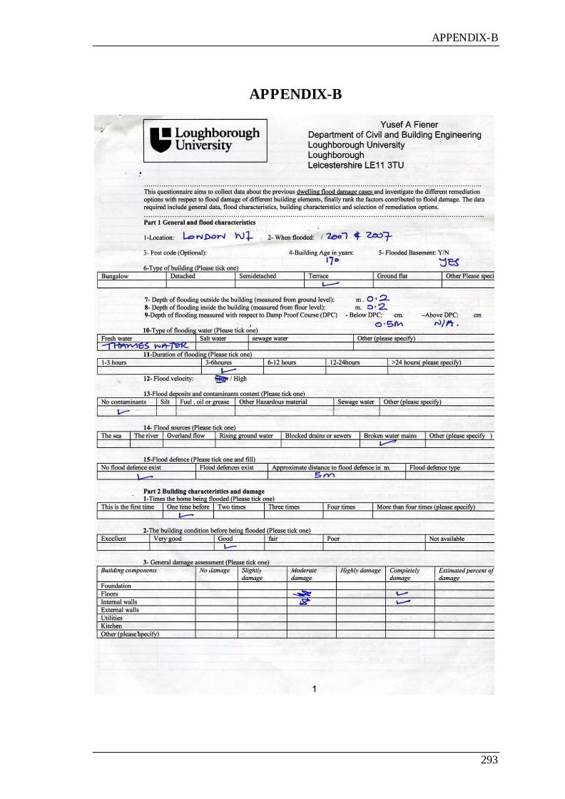
APPENDIX-B
293
APPENDIX-B
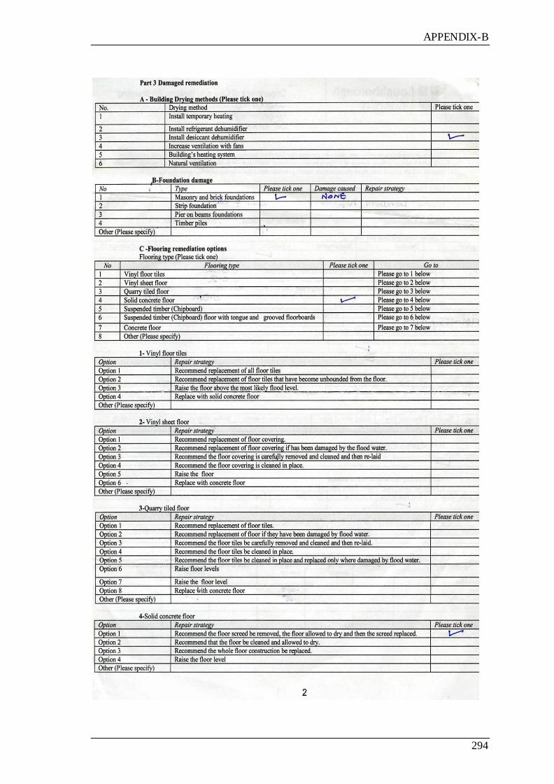
APPENDIX-B
294
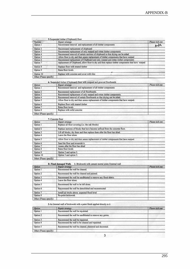
APPENDIX-B
295

APPENDIX-B
296

APPENDIX-B
297
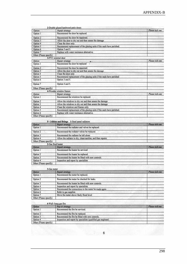
APPENDIX-B
298
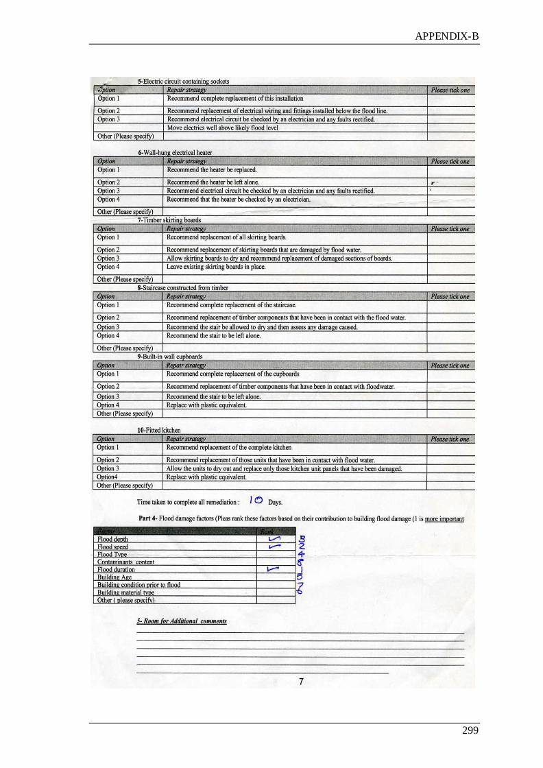
APPENDIX-B
299

APPENDIX-B
300
-Please tick the following box if you wish to receive of the result summary.
-Company name/Consultant:
If you have any queries please contact me via email at [email protected] or Tel: 07525356311.
Thank you for taking the time to complete this questionnaire. Please return it in the addressed, prepaid
envelope provided.
8

APPENDIX-C
301
APPENDIX-C
Data entry sheet for vulnerability assessment of residential building to flood damage
1-Case Number:………………… Date:……………… Time:……………….. 2-Address:……………………………………………………………………….
……………………………………………………………………………………
Surveyor Name:……………………….
Signature:……………………………..
comments :
……………………………………………………………………………………………
……………………………………………………………………………………………
No Factor description Please tick Yes or No
1 Geographic location of the building is within a flood risk
zone based on the flood maps provided by the
Environment Agency
Yes ( ) No( )
2 Building protected by flood defences. Yes ( ) No( )
3 Topography of the building site (the building is located on
the floor of a valley or at the bottom of a hill) Yes ( ) No( )
4 The building is close to an intermittent stream Yes ( ) No( )
5 The building is underlain by a chalk aquifer Yes ( ) No( )
6 The soil is often near saturation point or is impermeable Yes ( ) No( )
7 Duration of previous flood was greater than 12 hours Yes ( ) No( )
8 Depth of the previous flood was above the building floor Yes ( ) No( )
9 Issuing of flood warnings for this area in the past Yes ( ) No( )
10 Occurrence of sewer flooding in the past Yes ( ) No( )
11 The building has been flooded in the past Yes ( ) No( )
12 The building has a timber floor, walls or frames Yes ( ) No( )
13 The building has cracks in the walls near the floor level Yes ( ) No( )
14 The building incorporates gypsum plaster Yes ( ) No( )
15 The building has a mineral insulation Yes ( ) No( )
16 The condition of the building prior to the flood Yes ( ) No( )
17 The building has a chipboard, wood, vinyl, or rubber tiled
floor Yes ( ) No( )
18 The building has water resistant doors and windows, and
the kitchen has PVC or other water resistant material Yes ( ) No( )
19 Gas and electrical utilities are located above the flood
level Yes ( ) No( )
20 Existence of any flood resistance or resilience measures Yes ( ) No( )
21 Existence of backflow devices on sewer system Yes ( ) No( )
22 Previous flood damage Yes ( ) No( )
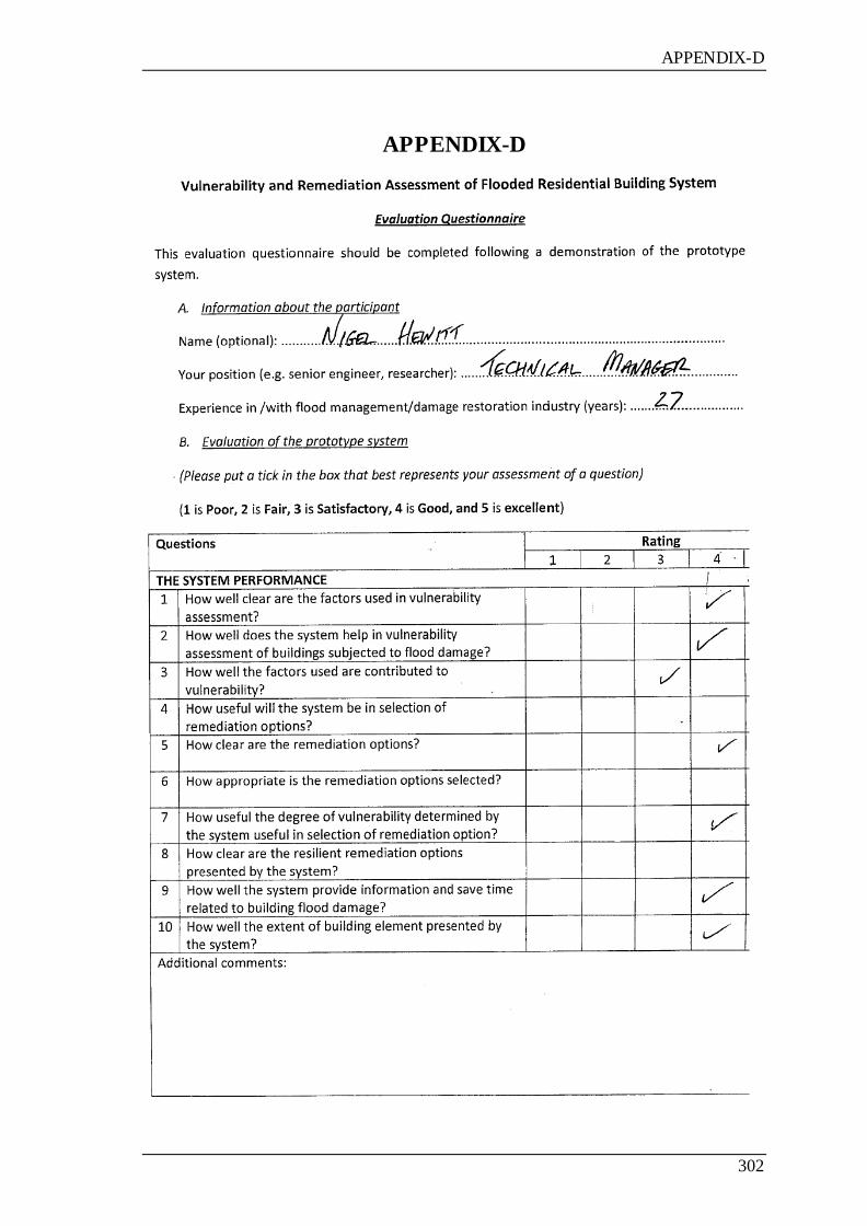
APPENDIX-D
302
APPENDIX-D
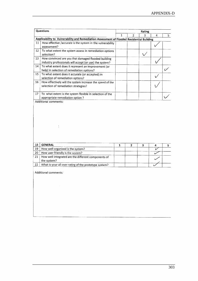
APPENDIX-D
303
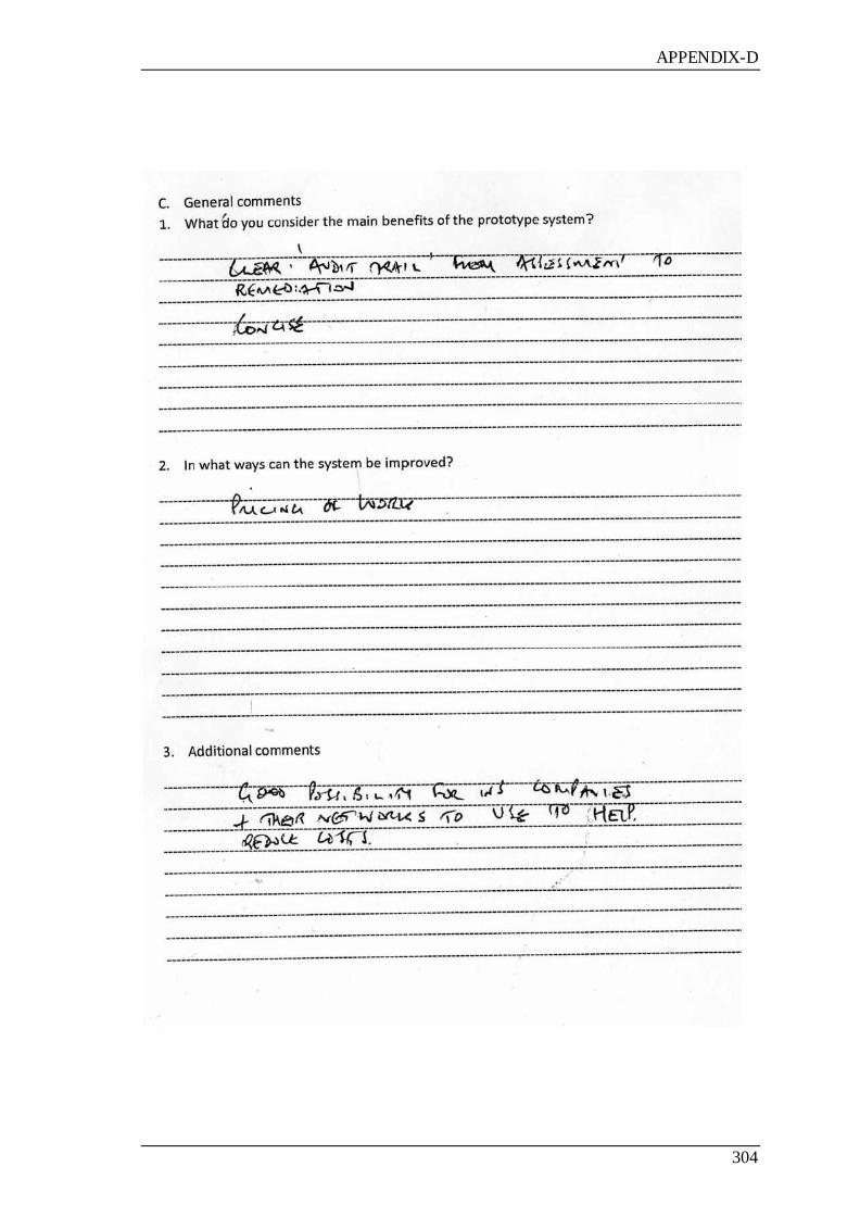
APPENDIX-D
304

APPENDIX-D
305