an electro-optical shutter for photography
TRANSCRIPT
An Electro-optical Shutter for Photography A. M. Z A R E M A S S O C I A T E A I E E
F. R. M A R S H A L L F. L. P O O L E M E M B E R A I E E
THE INCREASED
tempo of scientific activity during the last few years has resulted in a de-mand for optical investiga-tions of very rapidly chang-ing phenomena. Mechanical means have been employed to yield photographic ex-posure times down to about 50 microseconds, and special flash lamp and other tech-niques have resulted in photographic records with effec-tive exposure times in the microsecond range. The elec-tro-optical shutter provides a very versatile and practical means for obtaining exposure times over a very wide range. With the aid of such a shutter routine photo-graphic studies of electric discharges have been made using an effective exposure time of 0.000,000,04 second.
The novel feature of an electro-optical or Kerr cell shutter is that there are no mechanical moving parts, the speed of operation depending only upon the rapidity with which a required voltage can be applied to the Kerr cell electrodes. These electrodes are immersed in a fluid which exhibits uniaxial birefringence when under the influence of an electric field.
The phenomenon of electric birefringence was discovered by J. Kerr in 1875.1 One of the early applications of this effect was made in the construction of a light valve, now commonly called a Kerr cell shutter, for the measurement of very small time intervals.2 The ordinary Kerr cell is com-posed of two flat plates or electrodes immersed in a fluid which becomes birefringent upon the application of an elec-
The advent of the "all-electric" shutter makes possible the detailed photographic study of light from very rapidly changing self-luminous objects. Shutter control is sufficiently positive and accurate to permit operation at any pre-selected instant with a precision of 5 X 1 0 - 9
second. This article presents the theory and describes the development of this simple, reliable, and compact optical shutter which
utilizes a Kerr cell as a light valve.
H n s n ^ (C)
2. 3. 4.
5.
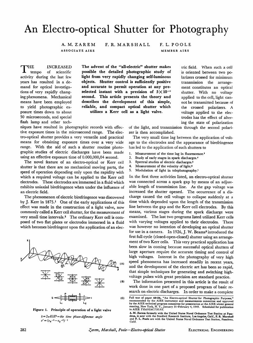
Figure 1. Principle of operation of a light valve
δ — 2πΚΙΕ2 = ί/ιε time phase-difference angle
trie field. When such a cell is oriented between two po-larizers crossed for minimum transmission the arrange-ment constitutes an optical shutter. With no voltage applied to the cell, light can-not be transmitted because of the crossed polarizers. A voltage applied to the elec-trodes has the effect of alter-ing the state of polarization
of the light, and transmission through the second polari-zer is then accomplished.
The very small time lag between the application of volt-age to the electrodes and the appearance of birefringence has led to the application of such shutters to 1. Measurement of the time lag in fluorescence.'
Study of early stages in spark discharges.4
Spectral studies of electric discharges.5
Measurement of the velocity of light.· Modulation of light in telephotography.'
In the first three activities listed, an electro-optical shutter was connected across a spark gap by means of an adjust-able length of transmission line. As the gap voltage was increased the shutter opened. The occurrence of a dis-charge caused the cell voltage to collapse suddenly at a time which depended upon the length of the transmission line between the gap and the Kerr cell electrodes. By this means, various stages during the spark discharge were examined. The last two programs listed utilized Kerr cells with varying voltages applied to their electrodes. There was however no intention of developing an optical shutter for use in a camera. In 1926, J. W. Beams8 introduced the first full cycle (closed-open-closed) shutter using an arrange-ment of two Kerr cells. This very practical application has been slow in coming because successful optical shutters of large aperture require the accurate timing and control of high voltages. Interest in the photography of very high speed phenomena has increased steadily in recent years, and the development of the electric art has been so rapid, that simple techniques for generating and switching high-voltage pulses with great precision are standard practice.
The information presented in this article is the result of work done in one part of a proposed program of basic re-search on electric discharges. In order to make a complete Full text of paper 49-24, "An Electro-optical Shutter for Photographic Purposes," recommended by the AIEE instrument and measurements committee and approved by the AIEE technical program committee for presentation at the AIEE winter general meeting, New York, N. Y., January 31-February 4, 1949. Scheduled for publication in AIEE TRANSACTIONS. A. M. Zarem formerly with the United States Naval Ordnance Test Station at Pasa-dena, is now with the Stanford Research Institute, Los Angeles, Calif., F. R. Marshall and F. L. Poole are with the United States Naval Ordnance Test Station, Pasadena, Calif.
282 Zarem, Marshall, Poole—Electro-optical Shutter ELECTRICAL ENGINEERING
optical study of a phenomenon with a duration of a few microseconds, it was necessary to use a camera with a very accurately controllable shutter that would enable the attainment of exposure times of less than a microsecond. The electro-optical shutter was chosen as the only solution to this problem. By controlling the type, duration, and instant of application of the voltage pulse applied to the cell electrodes, the photographic records with effective exposure time of 0.000,000,04 second were obtained at preselected intervals during the life of the phenomena being studied.
THE ELECTRO-OPTICAL KERR EFFECT
If a beam of polarized light is passed through a medium which is optically anisotropic, the velocity with which the light travels in the material depends upon the direction of the electric vector in the incident light. This means the substance is birefringent, that is: the index of refraction depends upon the direction of propagation and the plane of polarization of the light traversing the medium. There are many known substances which are normally isotropic, but which exhibit the property of optical birefringence when subjected to an electrostatic field. This phenomenon is known as the electro-optical Kerr effect.9
In the simple case of a uniaxial birefringent material, there is one axis along which the index of refraction is not dependent upon the direction of the electric vector in the incident light. This axis is termed the optic axis of the material.10 Substances which exhibit the electro-optical Kerr effect become uniaxially birefringent under the influence of an electric field, the optic axis being in the direction of the field.
According to the present state of the theory, the electro-optical Kerr effect is related intimately to molecular struc-ture. It has been found that for a liquid or gas to exhibit a Kerr effect, it is essential that the individual molecules possess an aeolotropic optical polarizability with respect to a set of axes in the molecule. In addition, however, the molecules must have either a permanent dipole moment or must be anisotropically polarizable by the application of an electric field, or both. It is not surprising therefore that the materials with the largest Kerr constants also have high dielectric constants.n«12
The statistically random orientation of molecules for liquids and gases in the normal state results in a condition of optical isotropy. In general, the application of an electric field produces a polarization assymmetry and also a tend-ency for the molecules to prefer a definite orientation, mainly, because of the permanent dipole moment. The orienting effect, although opposed by the thermal mo-lecular motion, results in a more or less statistically average regular arrangement of molecules under the influence of the applied electric field. Under these conditions the sub-stance exhibits an over-all molecular assymmetry and, generally, optical anisotropy. Orientation of the molecules is not a necessity, however, as the induced electrical polariza-tion alone also will cause optical anisotropy, but for sub-stances with high Kerr constants, molecular orientation accounts for the largest part of the Kerr effect.13
The rapidity with which the molecules of a substance
a I Z o
0 10 20 30 40 50 60 70 80 90 100 110 120 130 140 150 160 170
(ψ) 100« VOLTAGE APPLIED TO SHUTTER-PERCENT OF "FULL OPEN" VOLTAGE
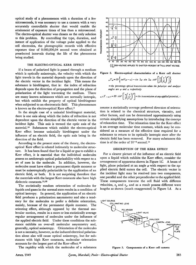
Figure 2. Electro-optical characteristics of a Kerr cell shutter
φΤα = 5θΙεο32(φ — <χ)—3Ϊη 2φ sin lot sin2 \~\— ) \(
= the percentage optical transmission when the polarizer and analyzer angles are φ and a respectively
jr/47~_7r/4 = 50 sin2 - l — j \ = the transmission at any applied potential, ι
assume a statistically average preferred direction of orienta-tion is related to the chemical structure, viscosity, and other factors, and can be determined approximately using certain simplifying assumptions by introducing the concept of relaxation time. The relaxation time for the Kerr effect is an average molecular time constant, which may be con-sidered as a measure of the effective time required for a substance to return to its optically isotropic state after the electric field has been removed. For many substances this time is of the order of 10~9 second.14
DESCRIPTION OF THE KERR EFFECT
For a clearer picture of the influence of an electric field upon a liquid which exhibits the Kerr effect, consider the arrangement of apparatus shown in Figure 1C. A beam of light, plane polarized at an angle φ with respect to the ap-plied electric field enters the cell. The electric vector in the incident light may be resolved into two components, one parallel and the other perpendicular to the applied field. These components traverse the cell fluid with different velocities, vx and vy, and as a result possess different wave lengths as shown (much exaggerated) in Figure \A. As a
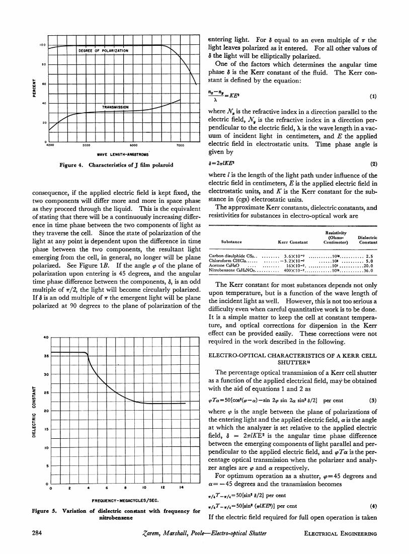
LIGHT SOURCE C0LLIMATING LENS
POLARIZER LIGHT VALVE
ANALYSER CAMERA LENS
PHOTOGRAPHIC " FILM
Figure 3. Components of a Kerr cell camera
APRIL 1949 garem, Marshall? Poole—Electro-optical Shutter 283
6 0
20
0
/
DFG RFF OF POLARIZATION
T RANS MISS ON ^
\ \ \
\
WAVE LENGTH-ANGSTROMS
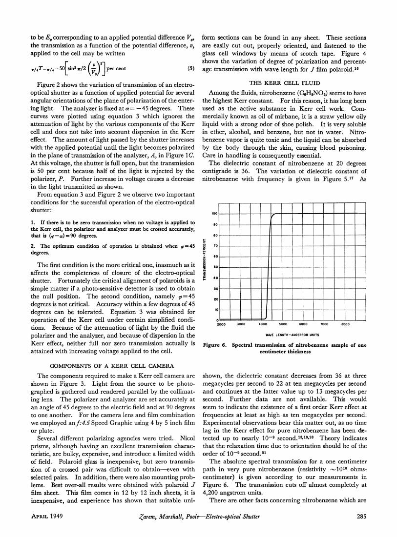
Figure 4. Characteristics of J film polaroid
consequence, if the applied electric field is kept fixed, the two components will differ more and more in space phase as they proceed through the liquid. This is the equivalent of stating that there will be a continuously increasing differ-ence in time phase between the two components of light as they traverse the cell. Since the state of polarization of the light at any point is dependent upon the difference in time phase between the two components, the resultant light emerging from the cell, in general, no longer will be plane polarized. See Figure IB. If the angle φ of the plane of polarization upon entering is 45 degrees, arid the angular time phase difference between the components, 5, is an odd multiple of 7r/2, the light will become circularly polarized. If δ is an odd multiple of π the emergent light will be plane polarized at 90 degrees to the plane of polarization of the
^_J
10 12 14
FREQUENCY-MEGACYCLES/SEC.
Figure 5. Variation of dielectric constant with frequency for nitrobenzene
entering light. For δ equal to an even multiple of π the light leaves polarized as it entered. For all other values of δ the light will be elliptically polarized.
One of the factors which determines the angular time phase δ is the Kerr constant of the fluid. The Kerr con-stant is defined by the equation:
Ψ~=ΚΕ* (1)
where Nx is the refractive index in a direction parallel to the electric field, Nv is the refractive index in a direction per-pendicular to the electric field, λ is the wave length in a vac-uum of incident light in centimeters, and E the applied electric field in electrostatic units. Time phase angle is given by
δ=2πΙΚΕ* (2)
where / is the length of the light path under influence of the electric field in centimeters, E is the applied electric field in electrostatic units, and K is the Kerr constant for the sub-stance in (cgs) electrostatic units.
The approximate Kerr constants, dielectric constants, and resistivities for substances in electro-optical work are
Substance
Garbon disulphide CS2. · . . Chloroform CHCli Acetone CjHeO Nitrobenzene C6H5NO2
Kerr Constant
3 . 6 X 1 0 - 7 - 3 . 2 X 1 0 - 7
1 6 X 1 0 - 7 . . . . 4 0 0 X 1 0 - 7
Resistivity (Ohms-
Centimeter)
10H 108 107 lOio
Dielectric Constant
2 .5 5 . 0
2 0 . 0 36 0
The Kerr constant for most substances depends not only upon temperature, but is a function of the wave length of the incident light as well. However, this is not too serious a difficulty even when careful quantitative work is to be done. It is a simple matter to keep the cell at constant tempera-ture, and optical corrections for dispersion in the Kerr effect can be provided easily. These corrections were not required in the work described in the following.
ELECTRO-OPTICAL CHARACTERISTICS OF A K E R R CELL S H U T T E R "
The percentage optical transmission of a Kerr cell shutter as a function of the applied electrical field, may-be obtained with the aid of equations 1 and 2 as
^>7a = 50[cos2(v>—a)— sin 2φ sin 2a sin2 δ/2] per cent (3)
where φ is the angle between the plane of polarizations of the entering light and the applied electric field, a is the angle at which the analyzer is set relative to the applied electric field, δ = 2πΙΚΕ2 is the angular time phase difference between the emerging components of light parallel and per-pendicular to the applied electric field, and φΤα is the per-centage optical transmission when the polarizer and analy-zer angles are φ and a respectively.
For optimum operation as a shutter, $>=45 degrees and a= — 45 degrees and the transmission becomes ,r/47"-,r/4 = 50[sini δ/2] per cent
^ r - ^ / ^ S O l s i n * (πΙΚΕ*)] per cent (4)
If the electric field required for full open operation is taken
284 parent, Marshall, Poole—Electro-optical Shutter ELECTRICAL ENGINEERING
to be E0 corresponding to an applied potential difference V0>
the transmission as a function of the potential difference, », applied to the cell may be written
r / 4 r _ T / 4 = 5o| sin*τ/2 (ψ)\Ρ^ cent (5)
Figure 2 shows the variation of transmission of an electro-optical shutter as a function of applied potential for several angular orientations of the plane of polarization of the enter-ing light. The analyzer is fixed at a = — 45 degrees. These curves were plotted using equation 3 which ignores the attenuation of light by the various components of the Kerr cell and does not take into account dispersion in the Kerr effect. The amount of light passed by the shutter increases with the applied potential until the light becomes polarized in the plane of transmission of the analyzer, A, in Figure 1C At this voltage, the shutter is full open, but the transmission is 50 per cent because half of the light is rejected by the polarizer, P. Further increase in voltage causes a decrease in the light transmitted as shown.
From equation 3 and Figure 2 we observe two important conditions for the successful operation of the electro-optical shutter:
1. If there is to be zero transmission when no voltage is applied to the Kerr cell, the polarizer and analyzer must be crossed accurately, that is (<p—a) « 9 0 degrees.
2. The optimum condition of operation is obtained when »̂ = 45 degrees.
The first condition is the more critical one, inasmuch as it affects the completeness of closure of the electro-optical shutter. Fortunately the critical alignment of polaroids is a simple matter if a photo-sensitive detector is used to obtain the null position. The second condition, namely φ=Α5 degrees is not critical. Accuracy within a few degrees of 45 degrees can be tolerated. Equation 3 was obtained for operation of the Kerr cell under certain simplified condi-tions. Because of the attenuation of light by the fluid the polarizer and the analyzer, and because of dispersion in the Kerr effect, neither full nor zero transmission actually is attained with increasing voltage applied to the cell.
COMPONENTS OF A KERR CELL CAMERA
The components required to make a Kerr cell camera are shown in Figure 3. Light from the source to be photo-graphed is gathered and rendered parallel by the collimat-ing lens. The polarizer and analyzer are set accurately at an angle of 45 degrees to the electric field and at 90 degrees to one another. For the camera lens and film combination we employed an/:4.5 Speed Graphic using 4 by 5 inch film or plate.
Several different polarizing agencies were tried. Nicol prisms, although having an excellent transmission charac-teristic, are bulky, expensive, and introduce a limited width of field. Polaroid glass is inexpensive, but zero transmis-sion of a crossed pair was difficult to obtain—even with selected pairs. In addition, there were also mounting prob-lems. Best over-all results were obtained with polaroid / film sheet. This film comes in 12 by 12 inch sheets, it is inexpensive, and experience has shown that suitable uni-
form sections can be found in any sheet. These sections are easily cut out, properly oriented, and fastened to the glass cell windows by means of scotch tape. Figure 4 shows the variation of degree of polarization and percent-age transmission with wave length for / film polaroid.16
THE KERR CELL FLUID
Among the fluids, nitrobenzene (G6H6N02) seems to have the highest Kerr constant. For this reason, it has long been used as the active substance in Kerr cell work. Com-mercially known as oil of mirbane, it is a straw yellow oily liquid with a strong odor of shoe polish. It is very soluble in ether, alcohol, and benzene, but not in water. Nitro-benzene vapor is quite toxic and the liquid can be absorbed by the body through the skin, causing blood poisoning. Care in handling is consequently essential.
The dielectric constant of nitrobenzene at 20 degrees centigrade is 36. The variation of dielectric constant of nitrobenzene with frequency is given in Figure 5.17 As
^J
V
2000 3000 4000 5000 6000 7000 8000
WAVE LENGTH-ANGSTROM UNITS
Figure 6. Spectral transmission of nitrobenzene sample of one centimeter thickness
shown, the dielectric constant decreases from 36 at three megacycles per second to 22 at ten megacycles per second and continues at the latter value up to 13 megacycles per second. Further data are not available. This would seem to indicate the existence of a first order Kerr effect at frequencies at least as high as ten megacycles per second. Experimental observations bear this matter out, as no time lag in the Kerr effect for pure nitrobenzene has been de-tected up to nearly 10~9 second.18»19»20 Theory indicates that the relaxation time due to orientation should be of the order of 10~"9 second.21
The absolute spectral transmission for a one centimeter path in very pure nitrobenzene (resistivity ~101 0 ohms-centimeter) is given according to our measurements in Figure 6. The transmission cuts off almost completely at 4,200 angstrom units.
There are other facts concerning nitrobenzene which are
APRIL 1949 £arem> Marshall, Poole—Electro-optical Shutter 285
of interest. The refractive index is approximately 1.553. The dielectric strength of commercial oil of mirbane is about 45,000 volts per centimeter and its resistivity is of the order of 106 ohms-centimeter. When the liquid is puri-fied, the dielectric strength may be increased to 150,000 volts per centimeter and its resistivity brought up to 1010
ohms-centimeter.22 Under conditions of pulsed voltage, nitrobenzene undoubtedly will withstand much higher elec-trical stresses although no data have been found for such conditions. However, it has been reported that carbon disulfide will withstand a gradient of 106 volts per centi-meter for periods of the order of 10~"7 second.
The Kerr constant for nitrobenzene as determined by electrostatic methods has been shown to be directly related to its purity as indicated by its resistivity. For this reason elaborate precautions usually are made to obtain the highest possible purity and resistivity. Because nitrobenzene is a powerful solvent, great care is exercised in the cleansing and handling operations encountered in the construction of Kerr cells.23 It should be noted here that the operation of a Kerr cell with voltage pulses of very brief duration (10~~7
second) may not require nitrobenzene of the very highest degree of purity. This matter has not yet been completely investigated.
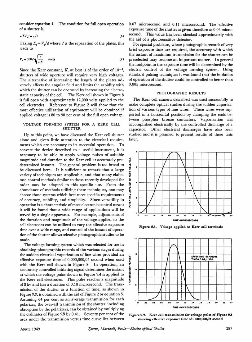
Figure 7 illustrates dispersion in the Kerr constant for nitrobenzene.24
H- APPROX.^DJA.
APPROX
SECTION A A
MATERIAL: PYREX GLASS
-.010 DIA. TUNGSTEN ROD
^»»■"»Uizzzyn:
•, SURFACES TO BE PARALLEL TO .004
A ΤΤΤ-Γ//"""*
SECTION BB
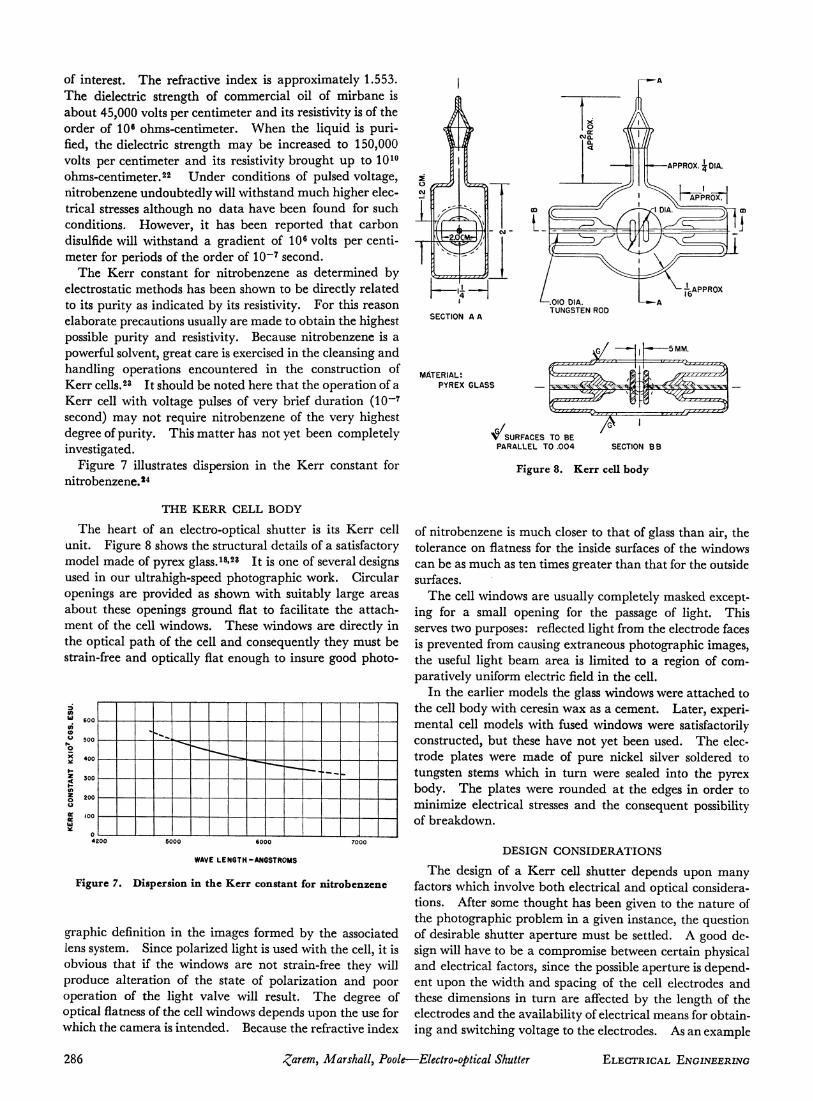
Figure 8. Kerr cell body
THE KERR CELL BODY
The heart of an electro-optical shutter is its Kerr cell unit. Figure 8 shows the structural details of a satisfactory model made of pyrex glass.18»23 It is one of several designs used in our ultrahigh-speed photographic work. Circular openings are provided as shown with suitably large areas about these openings ground flat to facilitate the attach-ment of the cell windows. These windows are directly in the optical path of the cell and consequently they must be strain-free and optically flat enough to insure good photo-
3 CO IÜ
CO e o
H Z
CO 2 O
u
oe Ui
600
500
400
300
200
100
0
- « . .^
»
5000 6000
WAVE L E N G T H - A N G S T R O M S
Figure 7. Dispersion in the Kerr constant for nitrobenzene
graphic definition in the images formed by the associated lens system. Since polarized light is used with the cell, it is obvious that if the windows are not strain-free they will produce alteration of the state of polarization and poor operation of the light valve will result. The degree of optical flatness of the cell windows depends upon the use for which the camera is intended. Because the refractive index
of nitrobenzene is much closer to that of glass than air, the tolerance on flatness for the inside surfaces of the windows can be as much as ten times greater than that for the outside surfaces.
The cell windows are usually completely masked except-ing for a small opening for the passage of light. This serves two purposes: reflected light from the electrode faces is prevented from causing extraneous photographic images, the useful light beam area is limited to a region of com-paratively uniform electric field in the cell.
In the earlier models the glass windows were attached to the cell body with ceresin wax as a cement. Later, experi-mental cell models with fused windows were satisfactorily constructed, but these have not yet been used. The elec-trode plates were made of pure nickel silver soldered to tungsten stems which in turn were sealed into the pyrex body. The plates were rounded at the edges in order to minimize electrical stresses and the consequent possibility of breakdown.
DESIGN CONSIDERATIONS
The design of a Kerr cell shutter depends upon many factors which involve both electrical and optical considera-tions. After some thought has been given to the nature of the photographic problem in a given instance, the question of desirable shutter aperture must be settled. A good de-sign will have to be a compromise between certain physical and electrical factors, since the possible aperture is depend-ent upon the width and spacing of the cell electrodes and these dimensions in turn are affected by the length of the electrodes and the availability of electrical means for obtain-ing and switching voltage to the electrodes. As an example
286 Zarem> Marshall, Poole—Electro-optical Shutter ELECTRICAL ENGINEERING
consider equation 4. The condition for full open operation of a shutter is
*ΙΚΕΪ = *Ι1 (6)
Taking EQ= VJd where d is the separation of the plates, this leads to
^O=300<f.4/— volts \21K
(7)
Since the Kerr constant, iT, at best is of the order of 10~6, shutters of wide aperture will require very high voltages. The alternative of increasing the length of the plates ad-versely affects the angular field and limits the rapidity with which the shutter can be operated by increasing the electro-static capacity of the cell. The Kerr cell shown in Figure 8 is full open with approximately 12,000 volts applied to the cell electrodes. Reference to Figure 2 will show that the most effective utilization of equipment will be obtained if applied voltage is 80 to 90 per cent of the full open voltage.
VOLTAGE F O R M I N G SYSTEM F O R A K E R R CELL S H U T T E R
Up to this point, we have discussed the Kerr cell shutter alone and given little attention to the electrical require-ments which are necessary to its successful operation. To convert the device described to a useful instrument, it is necessary to be able to apply voltage pulses of suitable magnitude and duration to the Kerr cell at accurately pre-determined instants. The general problem is too broad to be discussed here. It is sufficient to remark that a large variety of techniques are applicable, and that many elabo-rate control methods similar to those recently developed for radar may be adapted to this specific use. From the abundance of methods utilizing these techniques, one may choose those systems which best meet specific requirements of accuracy, stability, and simplicity. Since versatility in operation is a characteristic of most electronic control means it will be found that a wide range of applications will be served by a single apparatus. For example, adjustments of the duration and magnitude of the voltage applied to the cell electrodes can be utilized to vary the effective exposure time over a wide range, and control of the instant of opera-tion of the shutter allows selective photographic studies to be made.
The voltage forming system which was selected for use in obtaining photographic records of the various stages during the sudden electrical vaporization of fine wires provided an effective exposure time of 0.000,000,04 second when used with the Kerr cell shown in Figure 8. In operation, an accurately controlled initiating signal determines the instant at which the voltage pulse shown in Figure 9A is applied to the Kerr cell electrodes. This pulse reaches a magnitude of 8 kv and has a duration of 0.18 microsecond. The trans-mission of the shutter as a function of time, as shown in Figure 92?, is obtained with the aid of Figure 2 or equation 5. Assuming 64 per cent as an average transmission for each polarizer, the over-all transmission of the shutter, including absorption by the polarizers, can be obtained by multiplying the ordinates of Figure 9B by 0.41. Seventy per cent of the area under the transmission versus time curve lies between
0.07 microsecond and 0.11 microsecond. The effective exposure time of the shutter is given therefore as 0.04 micro-second. This value has been checked approximately with the aid of a photosensitive detector.
For special problems, where photographic records of very brief exposure time are required, the accuracy with which the instant of maximum transmission for the shutter can be preselected may become an important matter. In general the midpoint in the exposure time will be determined by the electric control of the voltage forming system. Using standard pulsing techniques it was found that the initiation of operation of the shutter could be controlled to better than 0.005 microsecond.
P H O T O G R A P H I C RESULTS
The Kerr cell camera described was used successfully to make complete optical studies during the sudden vaporiza-tion of various types of fine wires. These wires were sup-ported in a horizontal position by clamping the ends be-tween phosphor bronze contactors. Vaporization was accomplished electrically by the controlled discharge of a capacitor. Other electrical discharges have also been studied and it is planned to present results of these tests later.
>t
1
bl 6
u K X
β
PO
TE
NT
IAL
AP
PLI
ED
u /
/ '
/
/
/
/
/ f
?^^
J TIME-MICROSECONDS
Figure 9A. Voltage applied to Kerr cell terminals
~r^T-
1 A
j
\
\
J^\
^ [
\
\
\
1
..i__
E T
L
V \
TECTI MEsC
^
VE EX >.04>U
POSUR SEC.
E
08 .10 12 .14 .16
TIME-MICROSECONDS
Figure 9B. Kerr cell transmission for voltage pulse of Figure 9 A showing effective exposure time of 0.000,000,04 second
APRIL 1949 J?arem, Marshall, Poole—Electro-optical Shutter 287
INITIATOR
SYNCHRONIZER
\ t
—̂ ELECTRICAL
OELAY
PHENOMENA
TRIGGER
V O L T A G E
FORMING
S Y S T E M
E L E C T R O -
O P T I C A L
C E L L
Figure 10. Block diagram of Kerr cell camera system
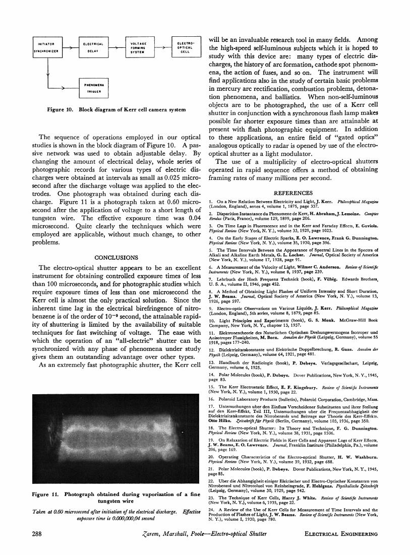
The sequence of operations employed in our optical studies is shown in the block diagram of Figure 10. A pas-sive network was used to obtain adjustable delay. By changing the amount of electrical delay, whole series of photographic records for various types of electric dis-charges were obtained at intervals as small as 0.025 micro-second after the discharge voltage was applied to the elec-trodes. One photograph was obtained during each dis-charge. Figure 11 is a photograph taken at 0.60 micro-second after the application of voltage to a short length of tungsten wire. The effective exposure time was 0.04 microsecond. Quite clearly the techniques which were employed are applicable, without much change, to other problems.
CONCLUSIONS
The electro-optical shutter appears to be an excellent instrument for obtaining controlled exposure times of less than 100 microseconds, and for photographic studies which require exposure times of less than one microsecond the Kerr cell is almost the only practical solution. Since the inherent time lag in the electrical birefringence of nitro-benzene is of the order of 10~9 second, the attainable rapid-ity of shuttering is limited by the availability of suitable techniques for fast switching of voltage. The ease with which the operation of an "all-electric" shutter can be synchronized with any phase of phenomena under study gives them an outstanding advantage over other types.
As an extremely fast photographic shutter, the Kerr cell
Figure 11. Photograph obtained during vaporization of a fine tungsten wire
Taken at 0.60 microsecond after initiation of the electrical discharge. Effective exposure time is 0.000,000,04 second
will be an invaluable research tool in many fields. Among the high-speed self-luminous subjects which it is hoped to study with this device are: many types of electric dis-charges, the history of arc formation, cathode spot phenom-ena, the action of fuses, and so on. The instrument will find applications also in the study of certain basic problems in mercury arc rectification, combustion problems, detona-tion phenomena, and ballistics. When non-self-luminous objects are to be photographed, the use of a Kerr cell shutter in conjunction with a synchronous flash lamp makes possible far shorter exposure times than are attainable at present with flash photographic equipment. In addition to these applications, an entire field of "gated optics" analogous optically to radar is opened by use of the electro-optical shutter as a light modulator.
The use of a multiplicity of electro-optical shutters operated in rapid sequence offers a method of obtaining framing rates of many millions per second.
REFERENCES
1. O n a New Relation Between Electricity and Light, J . Kerr. Philosophical Magazine (London, England) , series 4, volume 1, 1875, page 337.
2. Disparition Instantance du Phenomene de Kerr , H . Abraham, J . Lemoine. Comptes Rendus (Paris, France) , volume 129, 1899, page 206.
3. O n T ime Lags in Fluorescence and in the Ker r and Faraday Effects, E . Gaviola. Physical Review (New York, N . Y.) , volume 33, 1929, page 1023.
4. O n the Early Stages of Electric Sparks, E. O. Lawrence, Frank G. Dunnington. Physical Review (New York, N . Y.) , volume 35, 1930, page 396.
5. T h e T ime Intervals Between the Appearance of Spectral Lines in the Spectra of Alkali and Alkaline Ear th Metals, G. L. Locher. Journal, Optical Society of America (New York, N . Y.), volume 17, 1928, page 91 .
6. A Measurement of the Velocity of Light, Wilmer C. Anderson. Review of Scientific Instruments (New York, N . Y.) , volume 8, 1937, page 239.
7. Lehrbuch der Hoch Frequenz Technick (book), F. Vilbig. Edwards Brothers, U . S. A., volume I I , 1946, page 452.
8. A Method of Obtaining Light Flashes of Uniform Intensity and Short Durat ion, J. W. Beams. Journal, Optical Society of America (New York, N . Y.) , volume 13, 1926, page 597.
9. Electro-optic Observations on Various Liquids, J . Kerr. Philosophical Magazine (London, England) , 5th series, volume 8, 1879, page 85.
10. Light Principles and Experiments (book), G. S. Monk. McGraw-Hil l Book Company, New York, N . Y., chapter 13, 1937.
11 . Elektronentheorie des Naturl ichen Optischen Drehungsvermogens Isotroper und Anisotroper Flüssigkeiten, M. Born. Annalen der Physik (Leipzig, Germany) , volume 55 1918, pages 177-240.
12. Dielektrizitätskonstante und Elektrische Doppelbrechung, R. G a n s . Annalen der Physik (Leipzig, Germany) , volume 64, 1921, page 481.
13. H a n d b u c h der Radiologie (book), P . Debeye . Verlagsgesellschast, Leipzig, Germany, volume 6, 1925.
14. Polar Molecules (book), P . Debeye . Dover Publications, New York, N . Y., 1945, page 83.
15. T h e Ker r Electrostatic Effect, E . F . K i n g s b u r y . Review of Scientific Instruments (New York, N . Y.) , volume 1, 1930, page 22.
16. Polaroid Laboratory Products (bulletin), Polaroid Corporation, Cambridge, Mass.
17. Untersuchungen über den Einfluss Verscheidener Substitueten und ihrer Stellung auf den Kerr-Effekt, Tei l I I I , Untersuchungen über die Frequenzabhagigkeit der Dielektrizitätskonstante des Nitrobenzols und Beitrage zur Theorie des Kerr-Effekts. Otto Hilke. Zeitschrift für Physik (Berlin, Germany) , volume 103, 1936, page 350.
18. T h e Electro-optical Shut ter : Its Theory and Technique , F . G. Dunnington. Physical Review (New York, N . Y.), volume 38, 1931, page 1506.
19. O n Relaxation of Electric Fields in Ker r Cells and Apparent Lags of Ker r Effects. J . W. Beams , E. O. L a w r e n c e . Journal, Franklin Insti tute (Philadelphia, Pa. ) , volume 206, page 169.
20. Operat ing Characteristics of the Electro-optical Shutter, H . W. Washburn. Physical Review (New York, N . Y.) , volume 39, 1932, page 688.
21 . Polar Molecules (book), P . Debeye . Dover Publications, New York, N . Y., 1945, page 85 .
22. Über die Abhangigheit einiger Elektischer und Electro-Optischer Konstanten yon Nitrobenzol und Nitrotoluol von Reinheitsgrade, F . Hehlgans . Physikalische Zeitschrift (Leipzig, Germany) , volume 30, 1929, page 942.
23. T h e Technique of Ker r Cells, Harry J . White. Review of Scientific Instruments (New York, N . Y.) , volume 6, 1935, page 22.
24. A Review of the Use of Ker r Cells for Measurement of T ime Intervals and the Production of Flashes of Light, J . W. Beams. Review of Scientific Instruments (New York, N. Y.) , volume I, 1930, page 780.
288 parent, Marshall, Poole—Electro-optical Shutter ELECTRICAL ENGINEERING