an efficient lane detection algorithm for lane...
TRANSCRIPT
An Efficient Lane Detection AlgorithmFor Lane Departure Detection
Heechul Jung1, Junggon Min2 and Junmo Kim3
Abstract— In this paper, we propose an efficient lane de-tection algorithm for lane departure detection; this algorithmis suitable for low computing power systems like automobileblack boxes. First, we extract candidate points, which aresupport points, to extract a hypotheses as two lines. In thisstep, Haar-like features are used, and this enables us to use anintegral image to remove computational redundancy. Second,our algorithm verifies the hypothesis using defined rules. Theserules are based on the assumption that the camera is installedat the center of the vehicle. Finally, if a lane is detected, thena lane departure detection step is performed. As a result, ouralgorithm has achieved 90.16% detection rate; the processingtime is approximately 0.12 milliseconds per frame without anyparallel computing.
I. INTRODUCTION
Recently, many studies of Advanced Driver AssistanceSystems (ADAS) have been conducted to prevent car ac-cidents. Especially, the Lane Departure Warning System(LDWS), which is a system to warn drivers when the vehicleis moving out of its lane, is the most basic and necessarypart of the ADAS. This LDWS, which is usually based on alane detection algorithm using a camera, is operated underlow power and has to share resources such as the CentralProcessing Unit (CPU), Random Access Memory (RAM),and Read Only Memory (ROM) with other drivers assistantalgorithms. Also, to attract customers, the system shouldhave a low price. Therefore, the lane detection algorithmfor LDWS, should be compact, light, and efficient.
Previous lane detection algorithms can be classified intothree categories such as line or curve fitting based algorithms,color based algorithms, and learning based algorithms. Therepresentative curve fitting based algorithm is Lane detectionand tracking using B-Snake, which was proposed by Wang[1]. This algorithm has achieved good performance evenwhen the lane is curved, but it takes a long time to findthe lane. Another curve fitting lane detection algorithm wasproposed by Aly [2]; this algorithm is efficient and fast, butit is not suitable for computational systems of lower powerthan that of a desktop computer. Color based algorithms areusually fast and efficient [3]; however, they can be degradedin environments in which the illumination suffers extremechanges. Kim has proposed the Support Vector Machine
1Heechul Jung is with the Department of Electrical Engineering, KoreaAdvanced Institute of Science and Technology, Daejeon, Korea, heechulat kaist.ac.kr
2Junggon Min is with New Eye Vision company, Ulsan, Korea,push007 at nev.co.kr
3Junmo Kim is with Faculty of the Department of Electrical Engineering,Korea Advanced Institute of Science and Technology, Daejeon, Korea,junmo at ee.kaist.ac.kr
(SVM) based lane detection algorithm [4]. However, theweakness of learning based algorithms is that it is hardto collect training data using such algorithms. The mostrecently proposed algorithm is A Novel Lane DetectionSystem With Efficient Ground Truth Generation, which ispresented in [5]. This algorithm also requires training dataand it requires a high computational cost (0.8 second perframe). Consequently, it is not suitable for low computationalsystems.
In this work, we concentrate on a low computing systemthat has a 240 Mhz CPU and 10 MB available memory. Mostalgorithms are not applicable to a low computing systembecause they require high computational power. To developan efficient algorithm, we adopt two approaches: integralimage and local search. Also, a simple verification methodis used for filtering correct lane detection result. Finally,our algorithm has achieved considerably fast speed and hasshown promising results.
This paper is organized as follows. First, an efficient lanedetection algorithm for lane departure detection is proposedin Section 2. Second, evaluation of our algorithm is per-formed in Section 3, using our constructed database. Finally,based on these results, we conclude this paper, and considersome remaining issues, in Section 4.
II. PROPOSED ALGORHTM
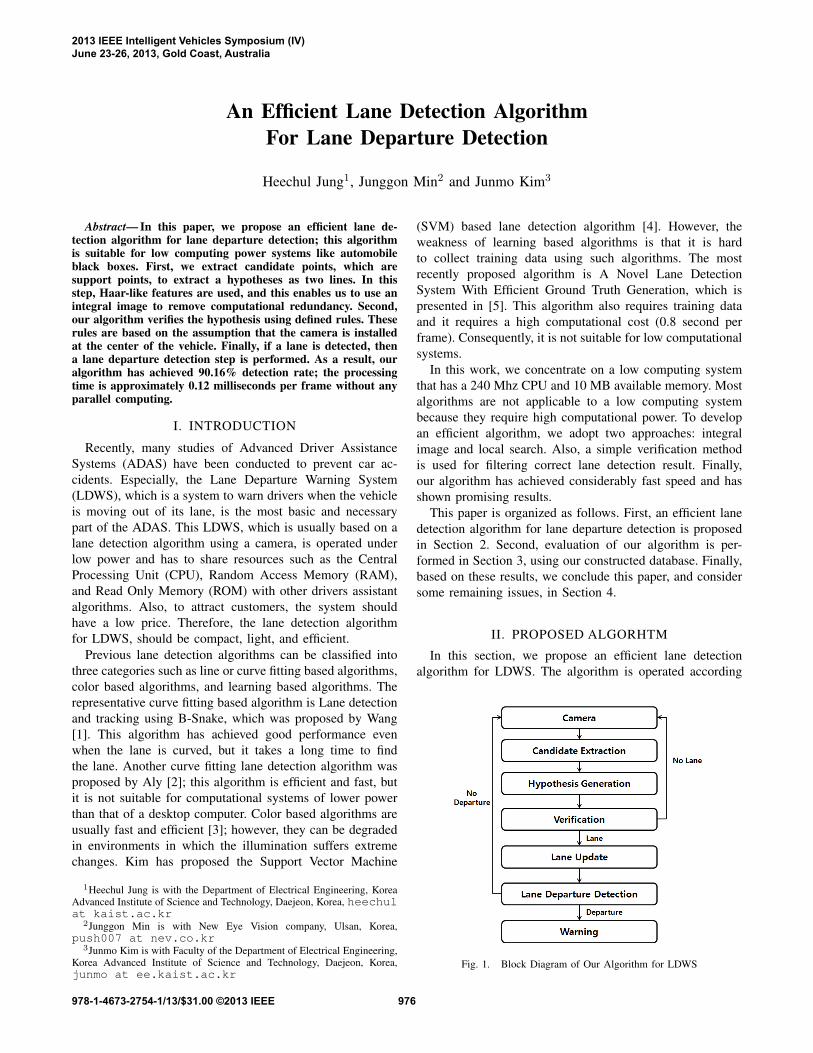
In this section, we propose an efficient lane detectionalgorithm for LDWS. The algorithm is operated according
Fig. 1. Block Diagram of Our Algorithm for LDWS
2013 IEEE Intelligent Vehicles Symposium (IV)June 23-26, 2013, Gold Coast, Australia
978-1-4673-2754-1/13/$31.00 ©2013 IEEE 976
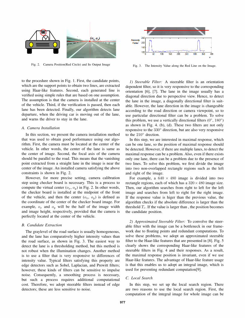
Fig. 2. Camera Position(Red Circle) and Its Output Image
to the procedure shown in Fig. 1. First, the candidate points,which are the support points to obtain two lines, are extractedusing Haar-like features. Second, each generated line isverified using simple rules that are based on one assumption.The assumption is that the camera is installed at the centerof the vehicle. Third, if the verification is passed, then eachlane has been detected. Finally, our algorithm detects lanedeparture, when the driving car is moving out of the lane,and warns the driver to stay in the lane.
A. Camera Installation
In this section, we present the camera installation methodthat was used to obtain good performance using our algo-rithm. First, the camera must be located at the center of thevehicle. In other words, the center of the lane is same asthe center of image. Second, the focal axis of the camerashould be parallel to the road. This means that the vanishingpoint extracted from a straight lane in the image is near thecenter of the image. An installed camera satisfying the aboveconstraints is shown in Fig. 2.
However, for more precise setting, camera calibrationstep using checker board is necessary. This is a process tocompute the virtual center (ox, oy) in Fig. 2. In other words,the checker board is installed at the midpoint of the frontof the vehicle, and then the center (ox, oy) is defined asthe coordinate of the center of the checker board image. Forexample, ox and oy will be the half of the image widthand image height, respectively, provided that the camera isperfectly located at the center of the vehicle.
B. Candidate Extraction
The graylevel of the road surface is usually homogeneous,and the lane has comparatively higher intensity values thanthe road surface, as shown in Fig. 3. The easiest way todetect the lane is a thresholding method, but this method isnot robust when the illumination changes. Another methodis to use a filter that is very responsive to differences ofintensity value. Typical filters satisfying this property areedge detectors such as Sobel, Laplacian, and Prewitt filters;however, these kinds of filters can be sensitive to impulsenoise. Consequently, a smoothing process is necessary,but such a process requires additional computationalcost. Therefore, we adopt steerable filters instead of edgedetectors; these are less sensitive to noise.
Fig. 3. The Intensity Value along the Red Line on the Image.
1) Steerable Filter: A steerable filter is an orientationdependent filter, so it is very responsive to the correspondingorientation [6], [7]. The lane in the image usually has adiagonal direction due to perspective view. Hence, to detectthe lane in the image, a diagonally directional filter is suit-able. However, the lane direction in the image is changeableaccording to the road direction or camera viewpoint, so touse particular directional filter can be a problem. To solvethis problem, we use a vertically directional filters (0◦, 180◦)as shown in Fig. 4. (b), (d). These two filters are not onlyresponsive to the 330◦ direction, but are also very responsiveto the 210◦ drection.
In this step, we are interested in maximal response, whichcan be one lane, so the position of maximal response shouldbe detected. However, if there are multiple lanes, to detect themaximal response can be a problem. Also, even if there existsonly one lane, there can be a problem due to the presence oftwo lines. To solve this problem, we first divide the imageinto two non-overlapped rectangle regions such as the leftand right of the image.
For example, a 640 × 480 image is divided into tworectangle regions, each of which has a 320×480 image size.Then, our algorithm searches from right to left for the leftimage and searches from left to right for the right image.If the response value is higer than the previous value, thealgorithm checks if the absolute difference is larger than thethreshold Tr. If the value is larger than , the position becomesthe candidate position.
2) Approximated Steerable Filter: To convolve the steer-able filter with the image can be a bottleneck in our frame-work due to floating points and redundant computations. Tosolve these problems, we adopt an approximated steerablefilter to the Haar-like features that are presented in [8]. Fig. 5clearly shows the corresponding Haar-like features of thesteerable filters in Fig. 4 and their responses. As a result,the maximal response position is invariant, even if we useHaar-like features. The advantage of Haar-like feature usageis that this enables us to adopt an integral image, which isused for preventing redundant computation[9].
C. Local Search
In this step, we set up the local search region. Thereare two reasons to use the local search region. First, thecomputation of the integral image for whole image can be
977
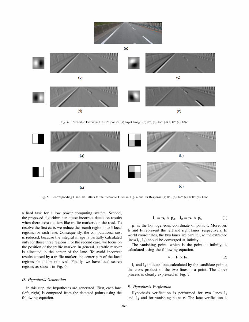
Fig. 4. Steerable Filters and Its Responses (a) Input Image (b) 0◦, (c) 45◦ (d) 180◦ (e) 135◦
Fig. 5. Corresponding Haar-like Filters to the Steerable Filter in Fig. 4 and Its Response (a) 0◦, (b) 45◦ (c) 180◦ (d) 135◦
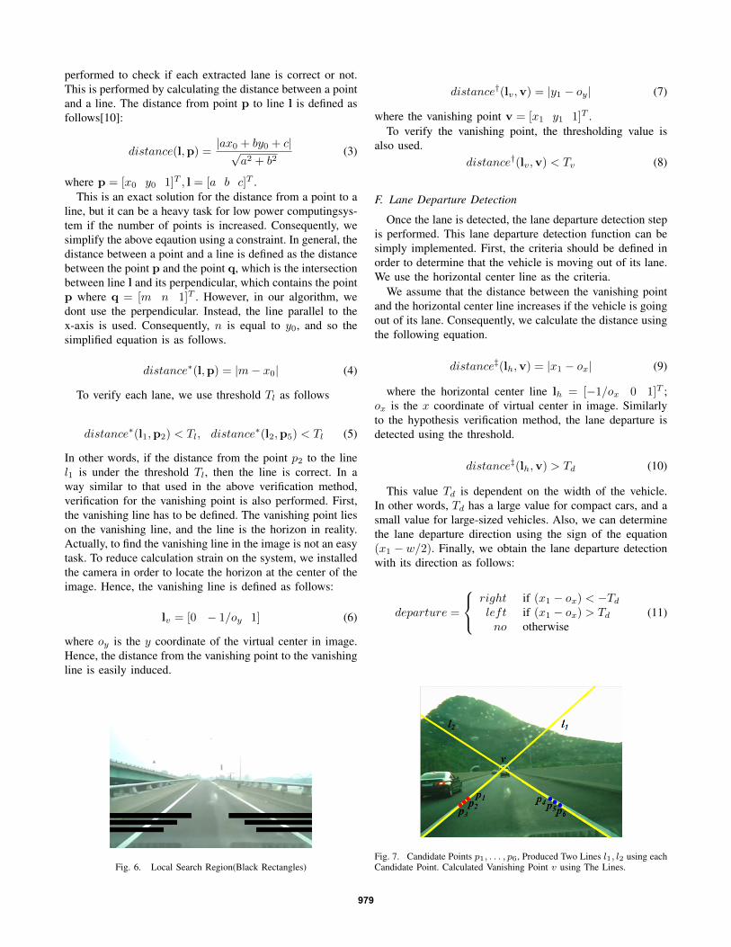
a hard task for a low power computing system. Second,the proposed algorithm can cause incorrect detection resultswhen there exist outliers like traffic markers on the road. Toresolve the first case, we reduce the search region into 3 localregions for each lane. Consequently, the computational costis reduced, because the integral image is partially calculatedonly for those three regions. For the second case, we focus onthe position of the traffic marker. In general, a traffic markeris allocated in the center of the lane. To avoid incorrectresults caused by a traffic marker, the center part of the localregions should be removed. Finally, we have local searchregions as shown in Fig. 6.
D. Hypothesis Generation
In this step, the hypotheses are generated. First, each lane(left, right) is computed from the detected points using thefollowing equation.
l1 = p1 × p3, l2 = p4 × p6 (1)
pi is the homogeneous coordinate of point i. Moreover,l1 and l2 represent the left and right lanes, respectively. Inworld coordinates, the two lanes are parallel, so the extractedlines(l1, l2) shoud be converged at infinity.
The vanishing point, which is the point at infinity, iscalculated using the following equation.
v = l1 × l2 (2)
l1 and l2 indicate lines calculated by the candidate points;the cross product of the two lines is a point. The aboveprocess is clearly expressed in Fig. 7
E. Hypothesis Verification
Hypothesis verification is performed for two lanes l1and, l2 and for vanishing point v. The lane verification is
978
performed to check if each extracted lane is correct or not.This is performed by calculating the distance between a pointand a line. The distance from point p to line l is defined asfollows[10]:
distance(l,p) =|ax0 + by0 + c|√
a2 + b2(3)
where p = [x0 y0 1]T , l = [a b c]T .This is an exact solution for the distance from a point to a
line, but it can be a heavy task for low power computingsys-tem if the number of points is increased. Consequently, wesimplify the above eqaution using a constraint. In general, thedistance between a point and a line is defined as the distancebetween the point p and the point q, which is the intersectionbetween line l and its perpendicular, which contains the pointp where q = [m n 1]T . However, in our algorithm, wedont use the perpendicular. Instead, the line parallel to thex-axis is used. Consequently, n is equal to y0, and so thesimplified equation is as follows.
distance∗(l,p) = |m− x0| (4)
To verify each lane, we use threshold Tl as follows
distance∗(l1,p2) < Tl, distance∗(l2,p5) < Tl (5)
In other words, if the distance from the point p2 to the linel1 is under the threshold Tl, then the line is correct. In away similar to that used in the above verification method,verification for the vanishing point is also performed. First,the vanishing line has to be defined. The vanishing point lieson the vanishing line, and the line is the horizon in reality.Actually, to find the vanishing line in the image is not an easytask. To reduce calculation strain on the system, we installedthe camera in order to locate the horizon at the center of theimage. Hence, the vanishing line is defined as follows:
lv = [0 − 1/oy 1] (6)
where oy is the y coordinate of the virtual center in image.Hence, the distance from the vanishing point to the vanishingline is easily induced.
Fig. 6. Local Search Region(Black Rectangles)
distance†(lv,v) = |y1 − oy| (7)
where the vanishing point v = [x1 y1 1]T .To verify the vanishing point, the thresholding value is
also used.distance†(lv,v) < Tv (8)
F. Lane Departure Detection
Once the lane is detected, the lane departure detection stepis performed. This lane departure detection function can besimply implemented. First, the criteria should be defined inorder to determine that the vehicle is moving out of its lane.We use the horizontal center line as the criteria.
We assume that the distance between the vanishing pointand the horizontal center line increases if the vehicle is goingout of its lane. Consequently, we calculate the distance usingthe following equation.
distance‡(lh,v) = |x1 − ox| (9)
where the horizontal center line lh = [−1/ox 0 1]T ;ox is the x coordinate of virtual center in image. Similarlyto the hypothesis verification method, the lane departure isdetected using the threshold.
distance‡(lh,v) > Td (10)
This value Td is dependent on the width of the vehicle.In other words, Td has a large value for compact cars, and asmall value for large-sized vehicles. Also, we can determinethe lane departure direction using the sign of the equation(x1 − w/2). Finally, we obtain the lane departure detectionwith its direction as follows:
departure =
right if (x1 − ox) < −Td
left if (x1 − ox) > Td
no otherwise(11)
Fig. 7. Candidate Points p1, . . . , p6, Produced Two Lines l1, l2 using eachCandidate Point. Calculated Vanishing Point v using The Lines.
979
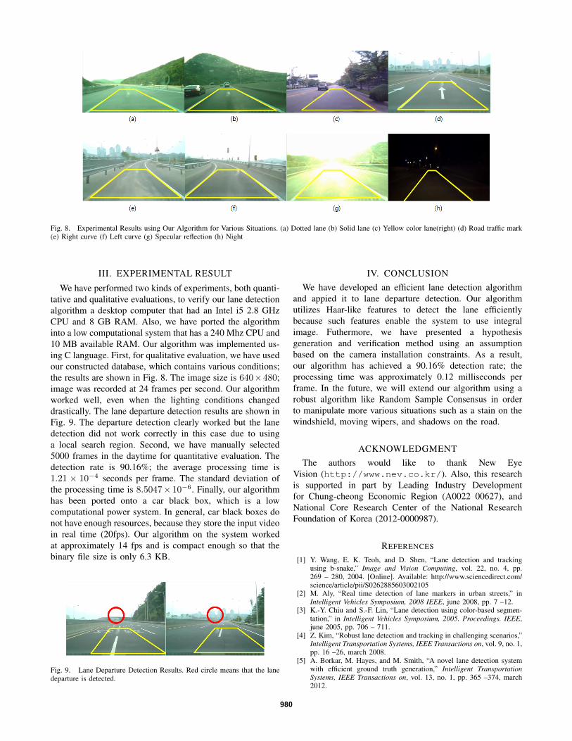
Fig. 8. Experimental Results using Our Algorithm for Various Situations. (a) Dotted lane (b) Solid lane (c) Yellow color lane(right) (d) Road traffic mark(e) Right curve (f) Left curve (g) Specular reflection (h) Night
III. EXPERIMENTAL RESULT
We have performed two kinds of experiments, both quanti-tative and qualitative evaluations, to verify our lane detectionalgorithm a desktop computer that had an Intel i5 2.8 GHzCPU and 8 GB RAM. Also, we have ported the algorithminto a low computational system that has a 240 Mhz CPU and10 MB available RAM. Our algorithm was implemented us-ing C language. First, for qualitative evaluation, we have usedour constructed database, which contains various conditions;the results are shown in Fig. 8. The image size is 640×480;image was recorded at 24 frames per second. Our algorithmworked well, even when the lighting conditions changeddrastically. The lane departure detection results are shown inFig. 9. The departure detection clearly worked but the lanedetection did not work correctly in this case due to usinga local search region. Second, we have manually selected5000 frames in the daytime for quantitative evaluation. Thedetection rate is 90.16%; the average processing time is1.21 × 10−4 seconds per frame. The standard deviation ofthe processing time is 8.5047× 10⁻⁶. Finally, our algorithmhas been ported onto a car black box, which is a lowcomputational power system. In general, car black boxes donot have enough resources, because they store the input videoin real time (20fps). Our algorithm on the system workedat approximately 14 fps and is compact enough so that thebinary file size is only 6.3 KB.
Fig. 9. Lane Departure Detection Results. Red circle means that the lanedeparture is detected.
IV. CONCLUSIONWe have developed an efficient lane detection algorithm
and appied it to lane departure detection. Our algorithmutilizes Haar-like features to detect the lane efficientlybecause such features enable the system to use integralimage. Futhermore, we have presented a hypothesisgeneration and verification method using an assumptionbased on the camera installation constraints. As a result,our algorithm has achieved a 90.16% detection rate; theprocessing time was approximately 0.12 milliseconds perframe. In the future, we will extend our algorithm using arobust algorithm like Random Sample Consensus in orderto manipulate more various situations such as a stain on thewindshield, moving wipers, and shadows on the road.
ACKNOWLEDGMENTThe authors would like to thank New Eye
Vision (http://www.nev.co.kr/). Also, this researchis supported in part by Leading Industry Developmentfor Chung-cheong Economic Region (A0022 00627), andNational Core Research Center of the National ResearchFoundation of Korea (2012-0000987).
REFERENCES
[1] Y. Wang, E. K. Teoh, and D. Shen, “Lane detection and trackingusing b-snake,” Image and Vision Computing, vol. 22, no. 4, pp.269 – 280, 2004. [Online]. Available: http://www.sciencedirect.com/science/article/pii/S0262885603002105
[2] M. Aly, “Real time detection of lane markers in urban streets,” inIntelligent Vehicles Symposium, 2008 IEEE, june 2008, pp. 7 –12.
[3] K.-Y. Chiu and S.-F. Lin, “Lane detection using color-based segmen-tation,” in Intelligent Vehicles Symposium, 2005. Proceedings. IEEE,june 2005, pp. 706 – 711.
[4] Z. Kim, “Robust lane detection and tracking in challenging scenarios,”Intelligent Transportation Systems, IEEE Transactions on, vol. 9, no. 1,pp. 16 –26, march 2008.
[5] A. Borkar, M. Hayes, and M. Smith, “A novel lane detection systemwith efficient ground truth generation,” Intelligent TransportationSystems, IEEE Transactions on, vol. 13, no. 1, pp. 365 –374, march2012.
980
[6] W. Freeman and E. Adelson, “The design and use of steerable filters,”Pattern Analysis and Machine Intelligence, IEEE Transactions on,vol. 13, no. 9, pp. 891 –906, sep 1991.
[7] T. Gao and H. Aghajan, “Self lane assignment using egocentric smartmobile camera for intelligent gps navigation,” 2012 IEEE ComputerSociety Conference on Computer Vision and Pattern RecognitionWorkshops, vol. 0, pp. 57–62, 2009.
[8] M. Villamizar, A. Sanfeliu, and J. Andrade-Cetto, “Computation ofrotation local invariant features using the integral image for real timeobject detection,” in Pattern Recognition, 2006. ICPR 2006. 18thInternational Conference on, vol. 4, 0-0 2006, pp. 81 –85.
[9] P. Viola and M. Jones, “Rapid object detection using a boosted cascadeof simple features,” in Computer Vision and Pattern Recognition,2001. CVPR 2001. Proceedings of the 2001 IEEE Computer SocietyConference on, vol. 1, 2001, pp. I–511 – I–518 vol.1.
[10] “Wikipedia, the free encyclopedia: Distance from a point to a line,”http://en.wikipedia.org/wiki/Distance from a point to a line.
981