an automated and user-friendly optical tweezers for biomolecular investigations (phd defense)
TRANSCRIPT
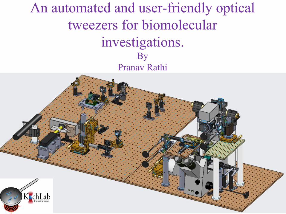
An automated and user-friendly optical tweezers for biomolecular
investigations.By
Pranav Rathi
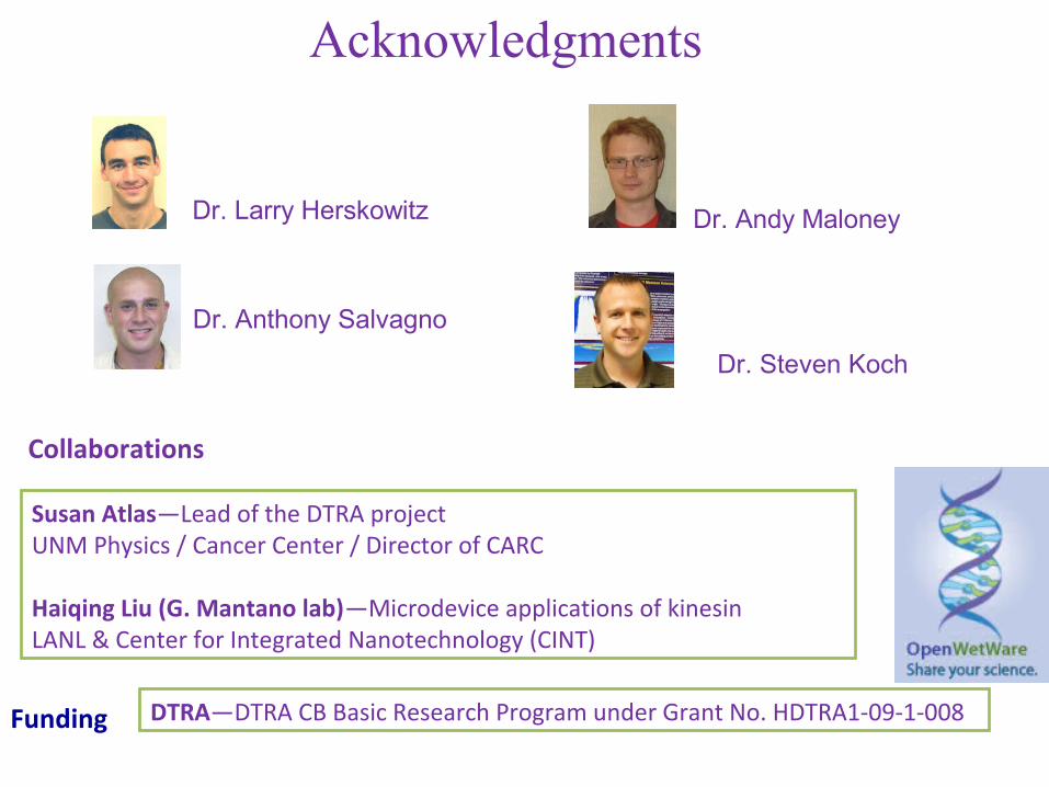
Susan Atlas—Lead of the DTRA projectUNM Physics / Cancer Center / Director of CARC
Haiqing Liu (G. Mantano lab)—Microdevice applications of kinesinLANL & Center for Integrated Nanotechnology (CINT)
Collaborations
Funding DTRA—DTRA CB Basic Research Program under Grant No. HDTRA1-09-1-008
Dr. Larry Herskowitz
Dr. Anthony Salvagno
Dr. Andy Maloney
Dr. Steven Koch
Acknowledgments
Outline
• Introduction to optical tweezers• Design and construction• Automation and control• Optical tweezers calibration• DNA sample preparation• Results
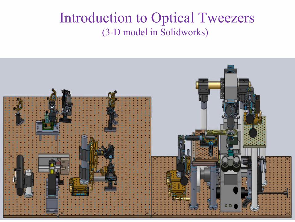
Introduction to Optical Tweezers(3-D model in Solidworks)
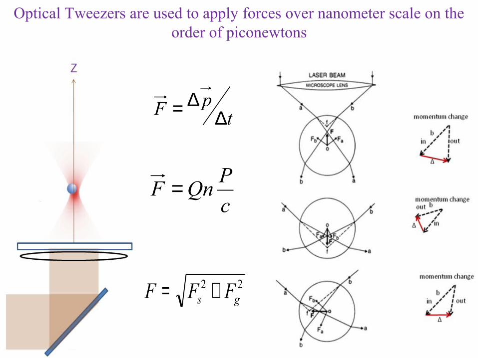
c
PQnF =
tpF ∆
∆=
22gs FFF +=
Optical Tweezers are used to apply forces over nanometer scale on the order of piconewtons
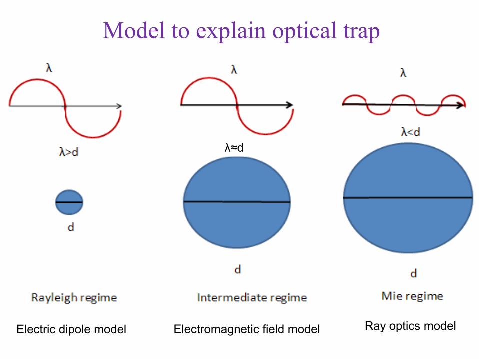
Model to explain optical trap
Ray optics modelElectric dipole model Electromagnetic field model
λ≈d
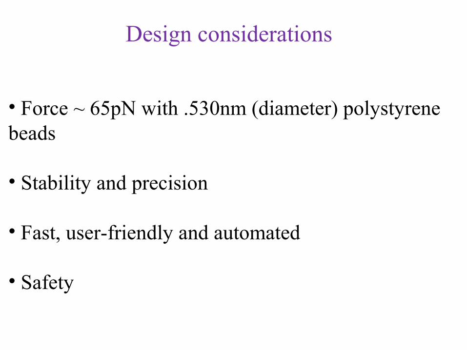
Design considerations
• Force ~ 65pN with .530nm (diameter) polystyrene beads
• Stability and precision
• Fast, user-friendly and automated
• Safety
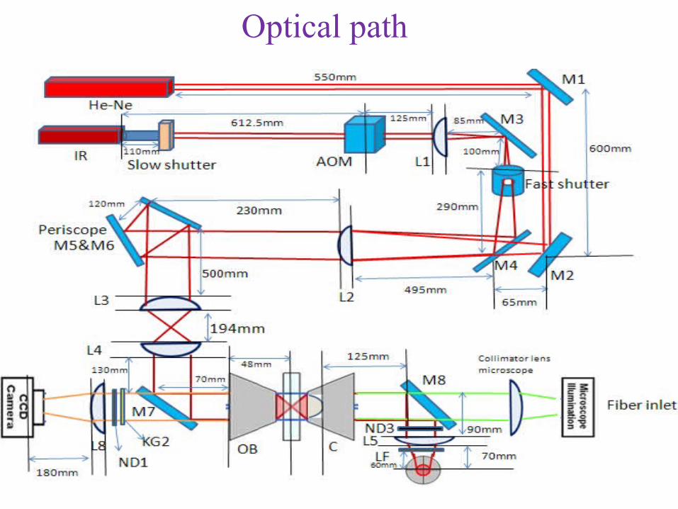
Optical path
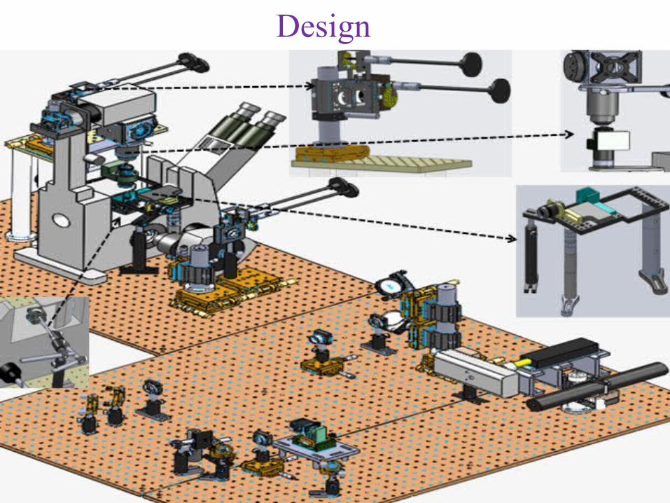
Design
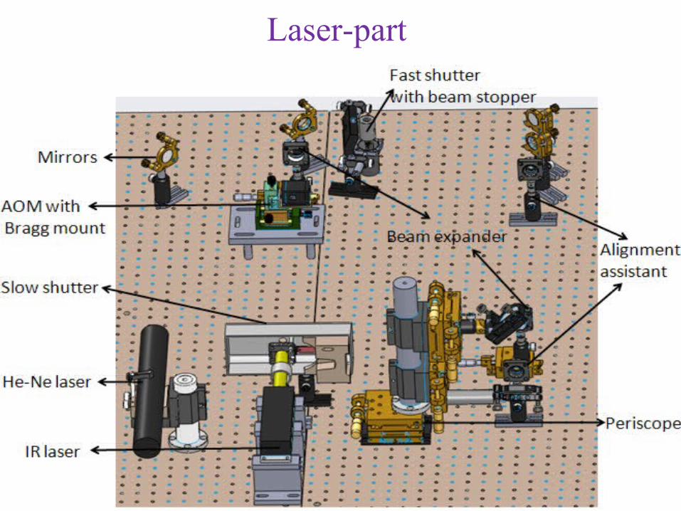
Laser-part
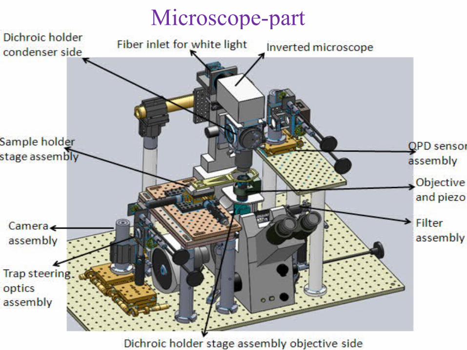
Microscope-part
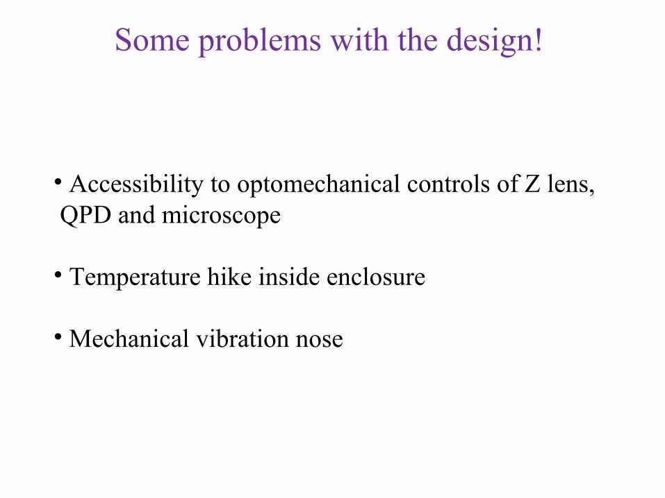
Some problems with the design!
• Accessibility to optomechanical controls of Z lens, QPD and microscope
• Temperature hike inside enclosure
• Mechanical vibration nose
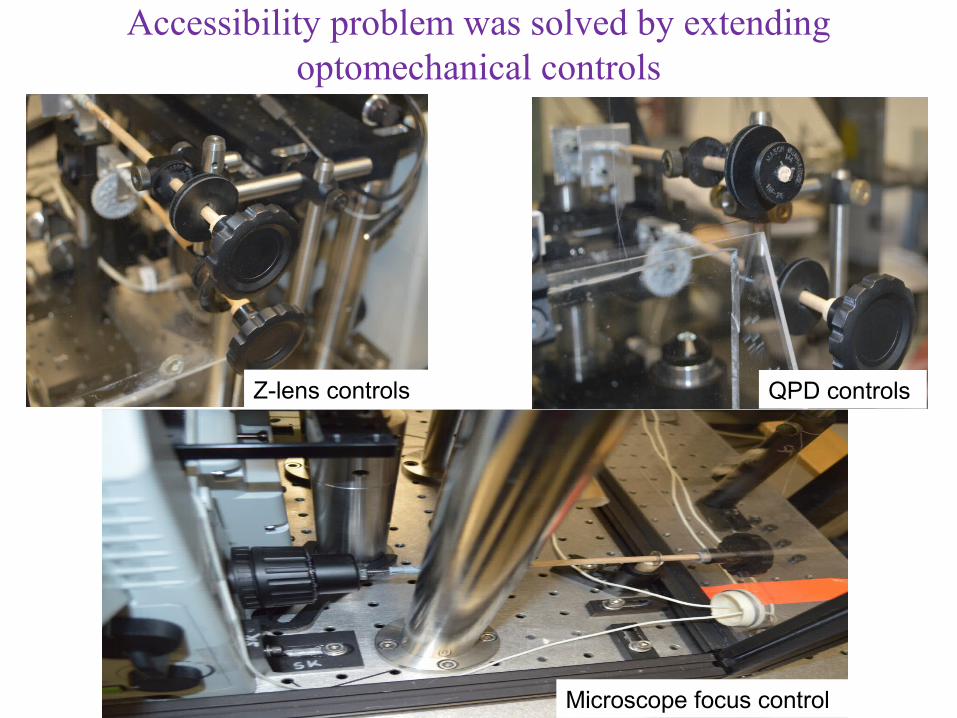
Accessibility problem was solved by extending optomechanical controls
Z-lens controls QPD controls
Microscope focus control
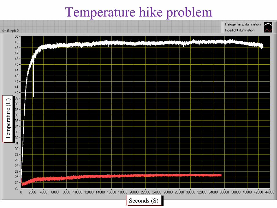
Temperature hike problemT
empe
ratu
re (
C)
Tem
pera
ture
(C
)
Seconds (S)Seconds (S)
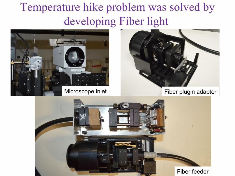
Fiber plugin adapterMicroscope inlet
Fiber feeder
Temperature hike problem was solved bydeveloping Fiber light
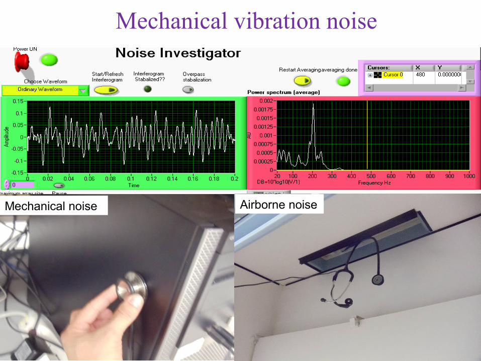
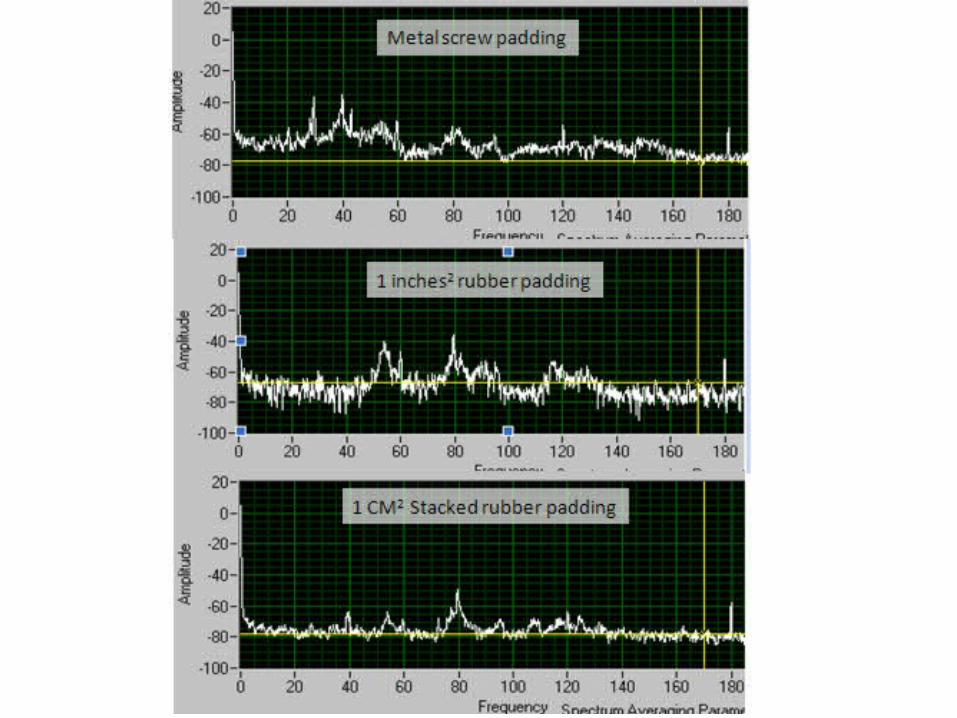
Mechanical noise Airborne noise
Mechanical vibration noise
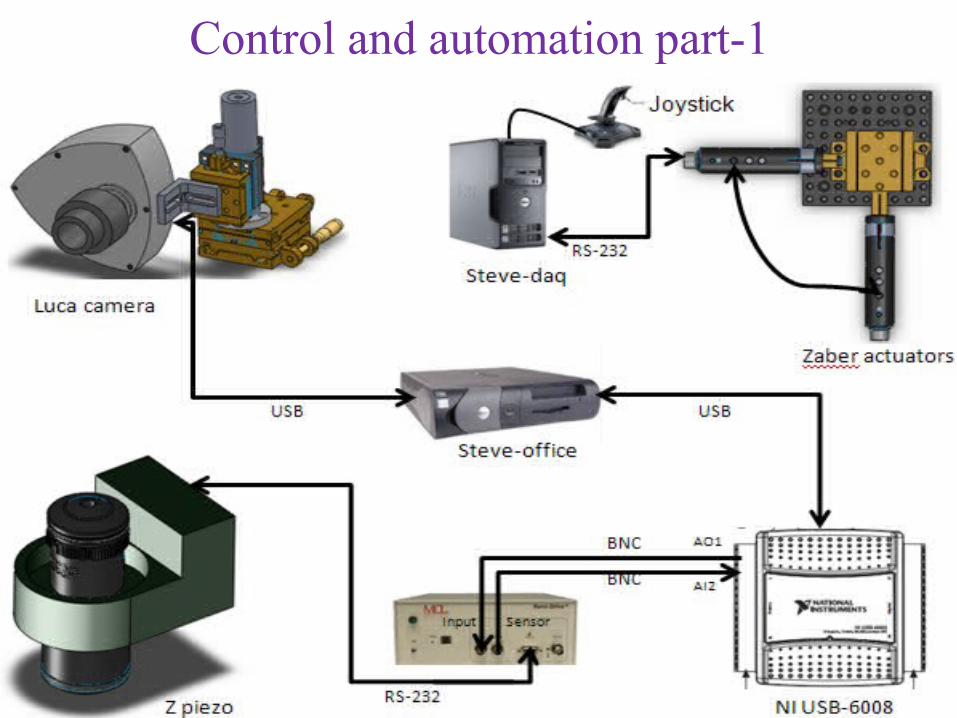
Control and automation part-1
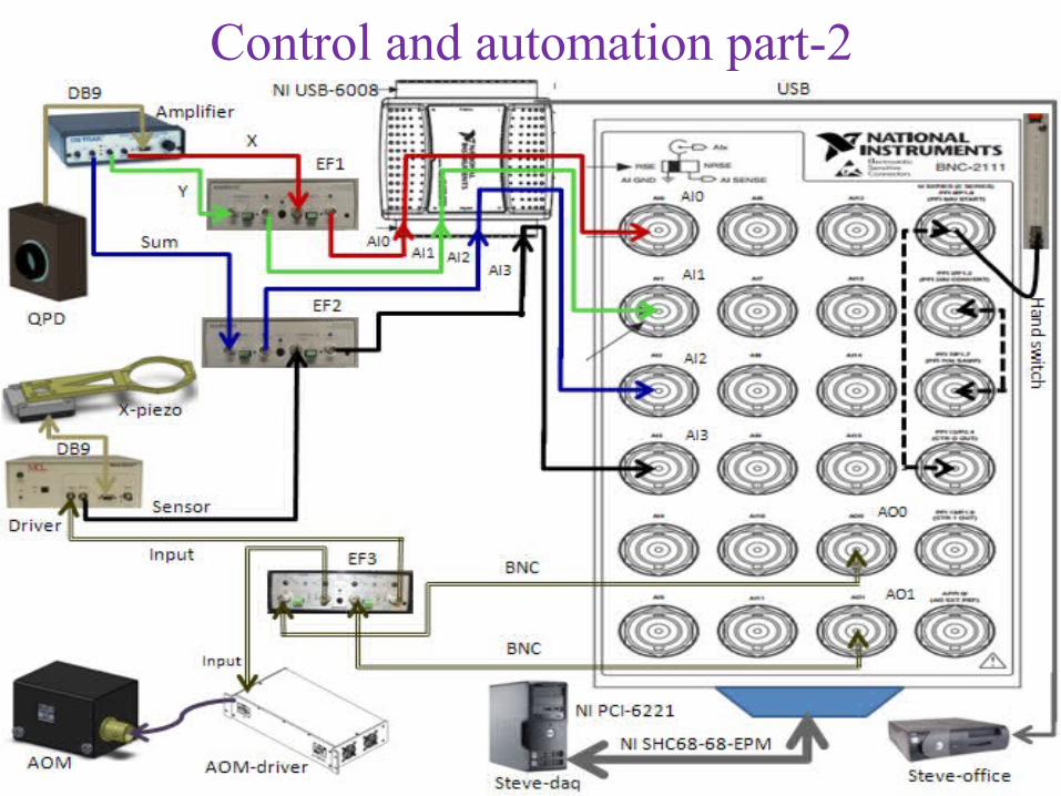
Control and automation part-2
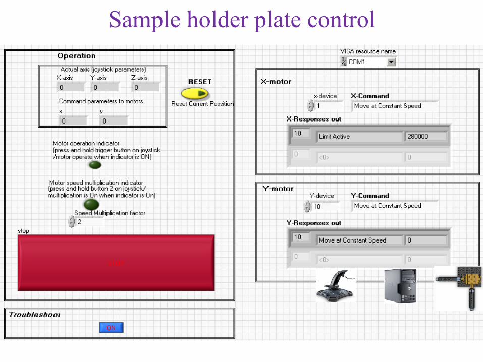
Sample holder plate control
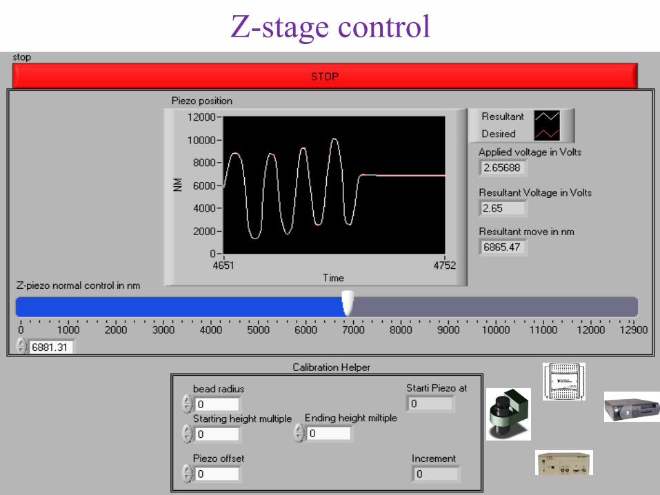
Z-stage control
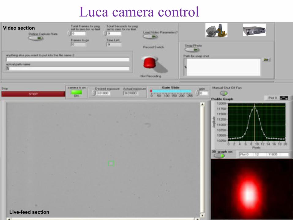
Video section
Live-feed section
Luca camera control
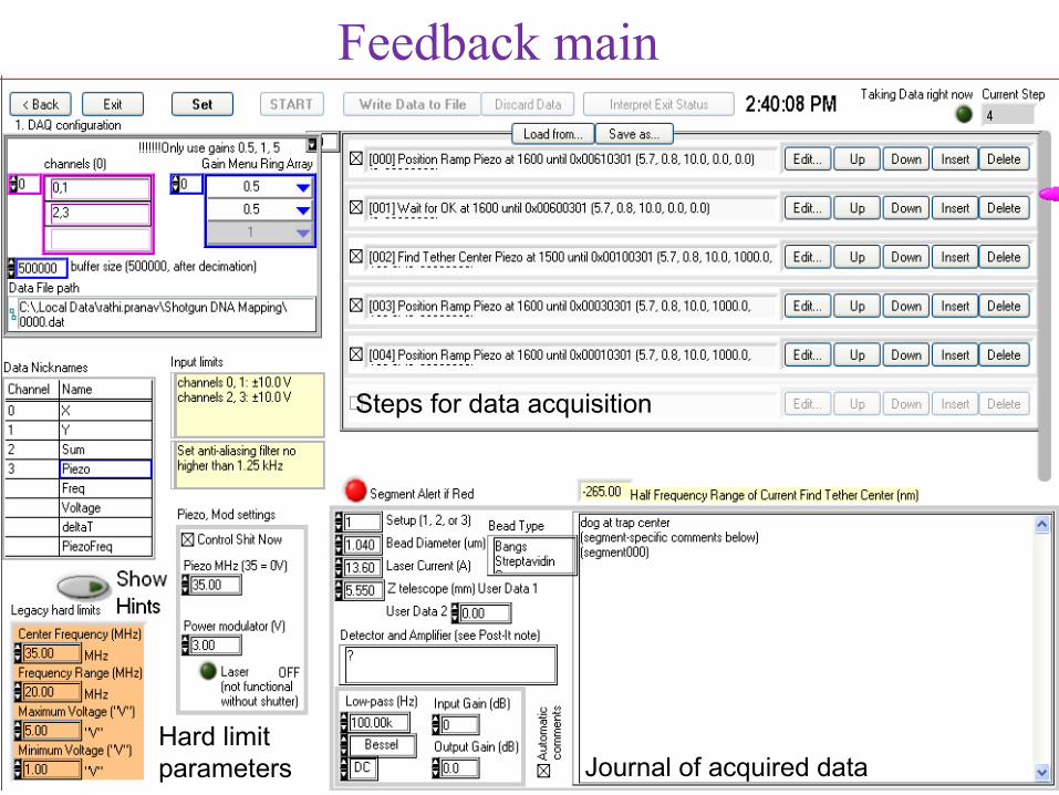
Steps for data acquisition
Journal of acquired dataHard limitparameters
Feedback main

Optical tweezers calibration
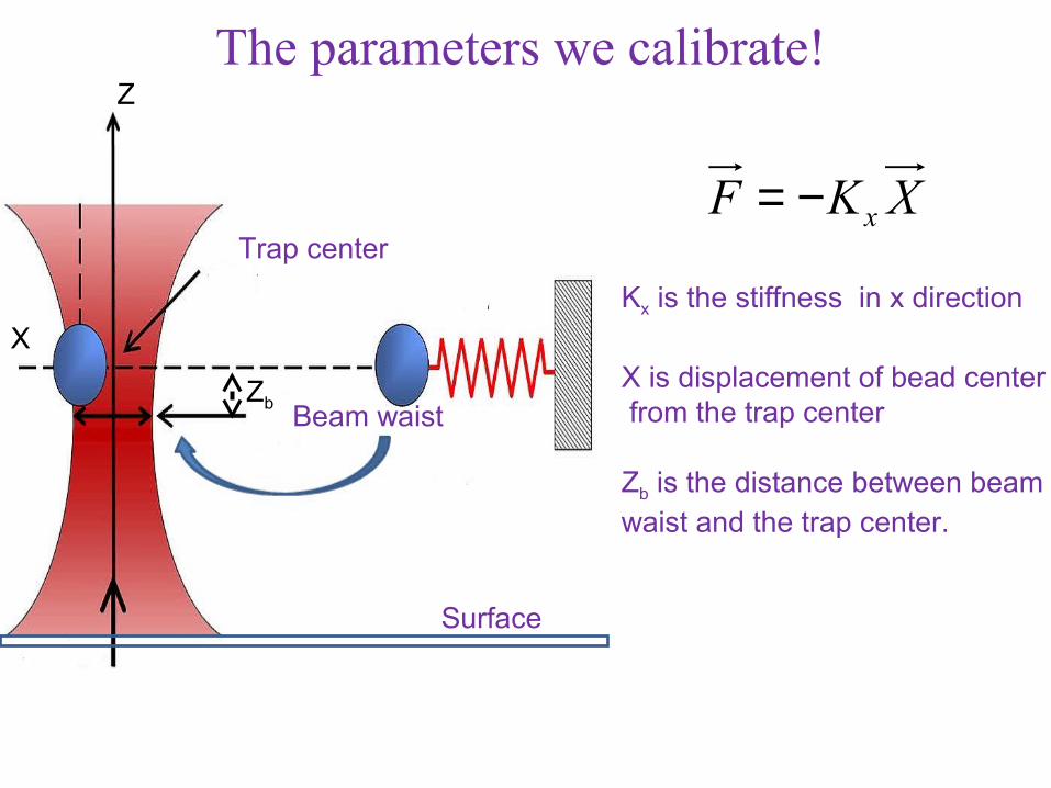
The parameters we calibrate!
XKF x−=
Kx is the stiffness in x direction
X is displacement of bead center from the trap center
Zb is the distance between beamwaist and the trap center.
X
Z
Trap center
Beam waist
Surface
Zb
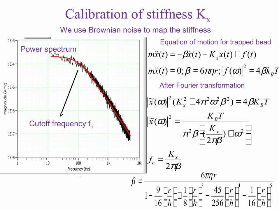
Calibration of stiffness Kx We use Brownian noise to map the stiffness
Tkfrtxm
tftxKtxtxm
B
x
βωπηβ
β
4)(;6;0)(
)()()()(2 ===
+−−=
After Fourier transformation
πβ
ωπβ
βπω
ββωπω
2
)2
(
)(~
4)4()(~
22
2
22222
xc
x
B
Bx
Kf
K
TKx
TKKx
=
+
=
=+
Power spectrumEquation of motion for trapped bead
Cutoff frequency fc
543
161
25645
81
169
1
6
−
−
+
−
=
hr
hr
hr
hr
rπηβ
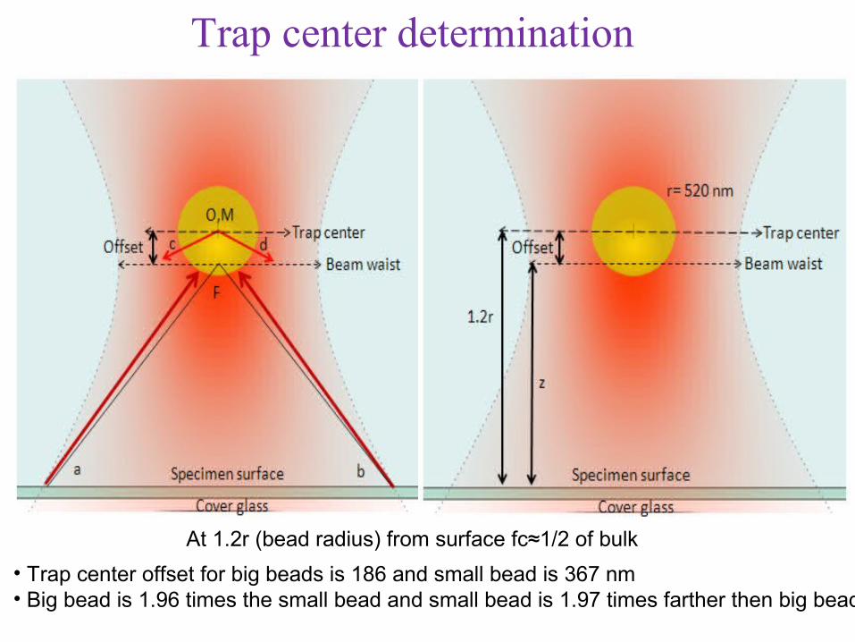
Trap center determination
At 1.2r (bead radius) from surface fc≈1/2 of bulk
• Trap center offset for big beads is 186 and small bead is 367 nm• Big bead is 1.96 times the small bead and small bead is 1.97 times farther then big bead
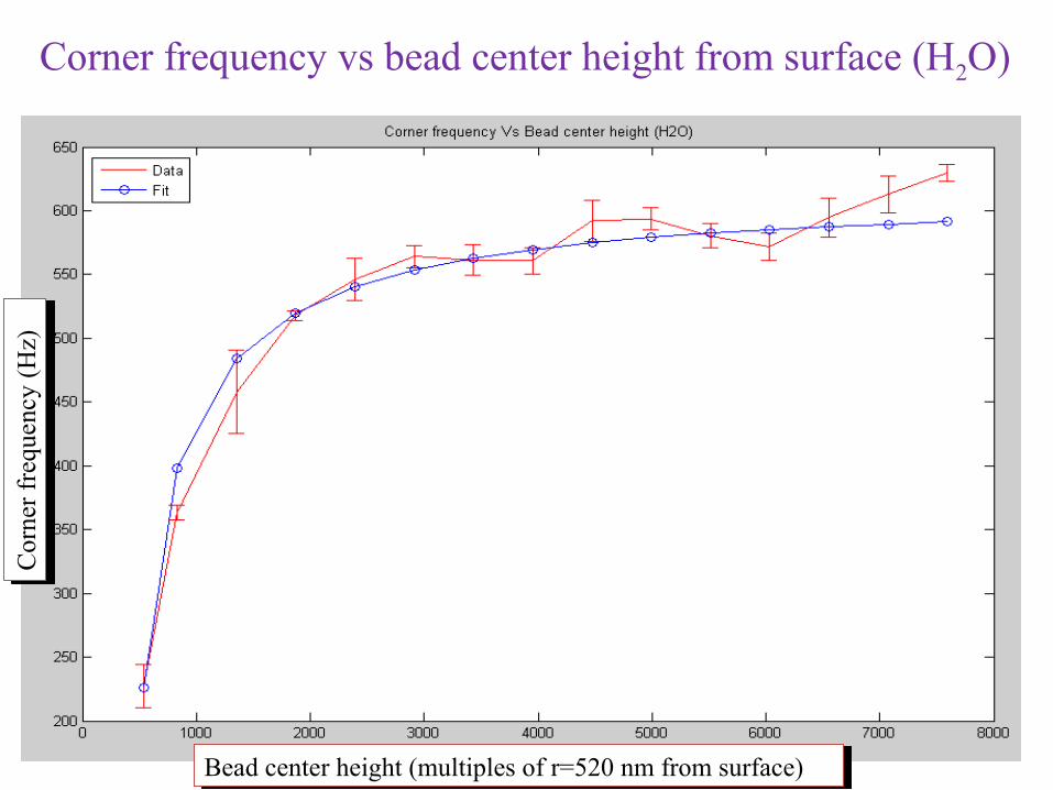
Corner frequency vs bead center height from surface (H2O)C
orne
r fr
eque
ncy
(Hz)
Cor
ner
freq
uenc
y (H
z)
Bead center height (multiples of r=520 nm from surface)Bead center height (multiples of r=520 nm from surface)
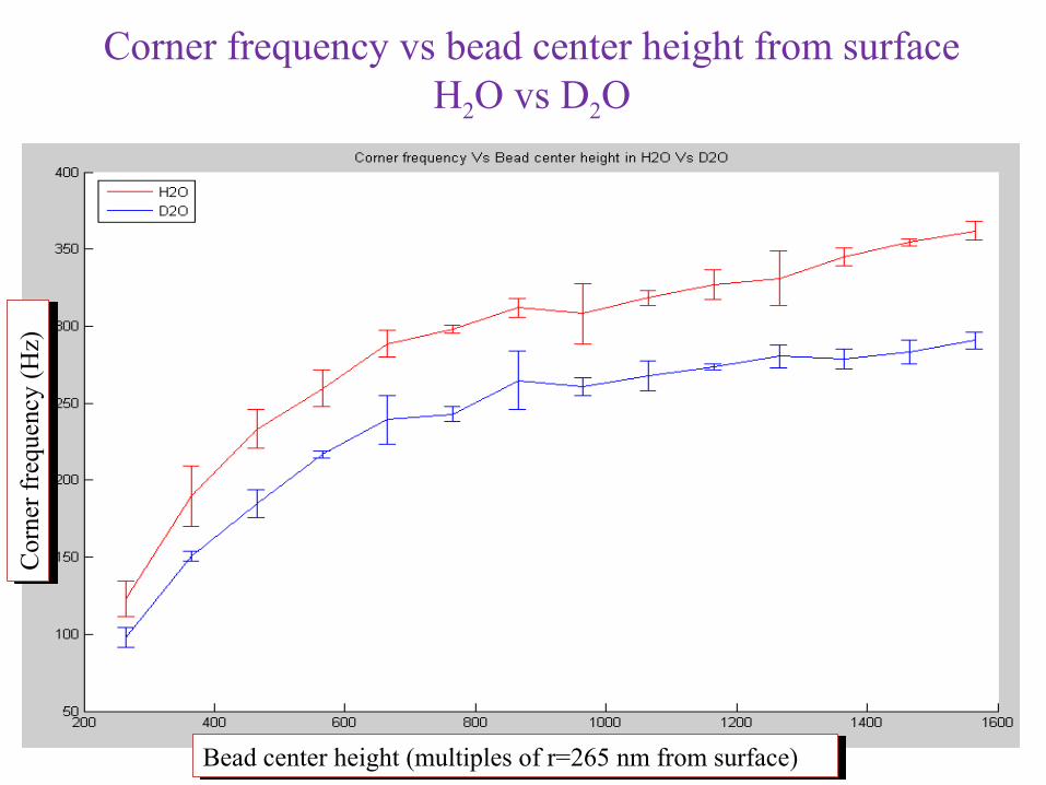
Corner frequency vs bead center height from surfaceH2O vs D2O
Cor
ner
freq
uenc
y (H
z)C
orne
r fr
eque
ncy
(Hz)
Bead center height (multiples of r=265 nm from surface)Bead center height (multiples of r=265 nm from surface)
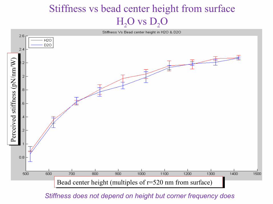
Stiffness vs bead center height from surfaceH2O vs D2O
Stiffness does not depend on height but corner frequency does
Perc
eive
d st
iffn
ess
(pN
/nm
/W)
Perc
eive
d st
iffn
ess
(pN
/nm
/W)
Bead center height (multiples of r=520 nm from surface)Bead center height (multiples of r=520 nm from surface)
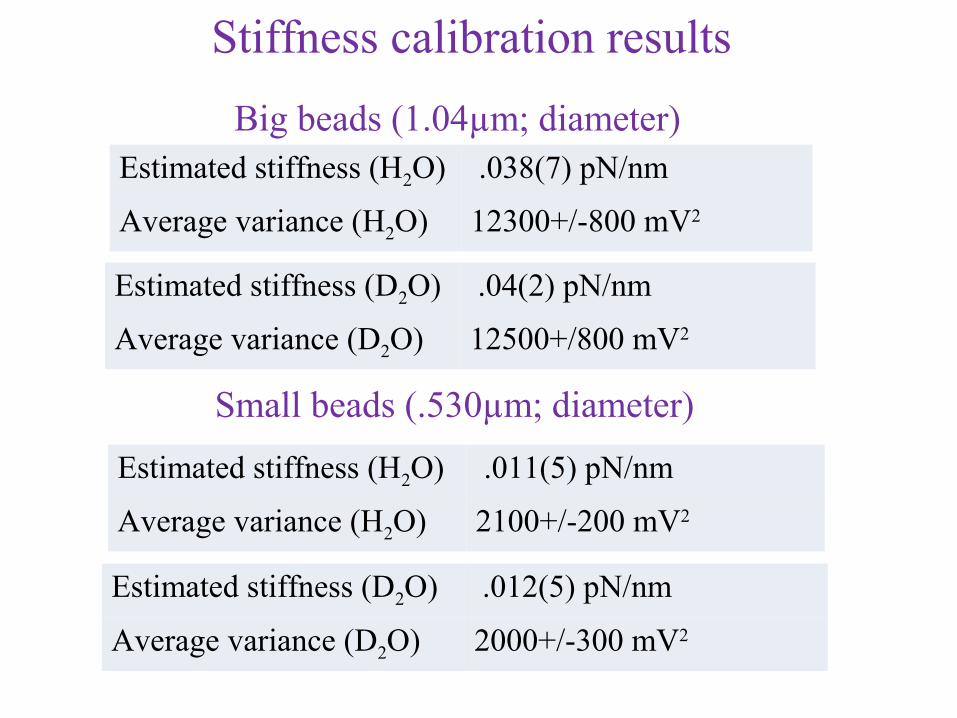
Estimated stiffness (H2O) .038(7) pN/nm
Average variance (H2O) 12300+/-800 mV2
Stiffness calibration results
Big beads (1.04µm; diameter)
Estimated stiffness (D2O) .04(2) pN/nm
Average variance (D2O) 12500+/800 mV2
Small beads (.530µm; diameter)
Estimated stiffness (H2O) .011(5) pN/nm
Average variance (H2O) 2100+/-200 mV2
Estimated stiffness (D2O) .012(5) pN/nm
Average variance (D2O) 2000+/-300 mV2
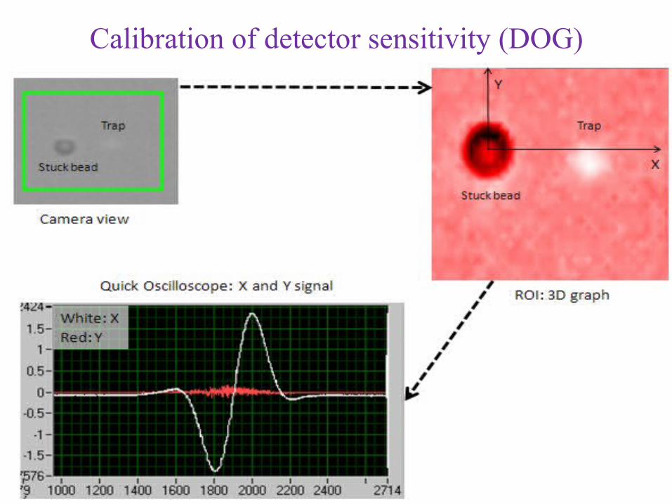
Calibration of detector sensitivity (DOG)
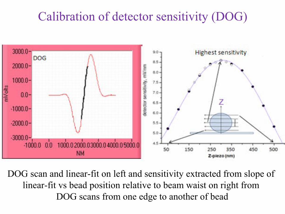
Calibration of detector sensitivity (DOG)
DOG scan and linear-fit on left and sensitivity extracted from slope of linear-fit vs bead position relative to beam waist on right from
DOG scans from one edge to another of bead
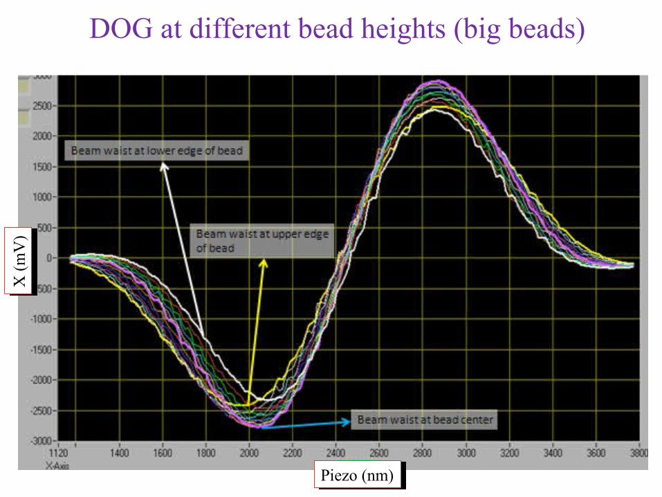
DOG at different bead heights (big beads)X
(m
V)
X (
mV
)
Piezo (nm)Piezo (nm)
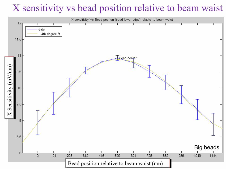
X sensitivity vs bead position relative to beam waist
Big beads
X S
ensi
tivi
ty (
mV
/nm
)X
Sen
siti
vity
(m
V/n
m)
Bead position relative to beam waist (nm)Bead position relative to beam waist (nm)
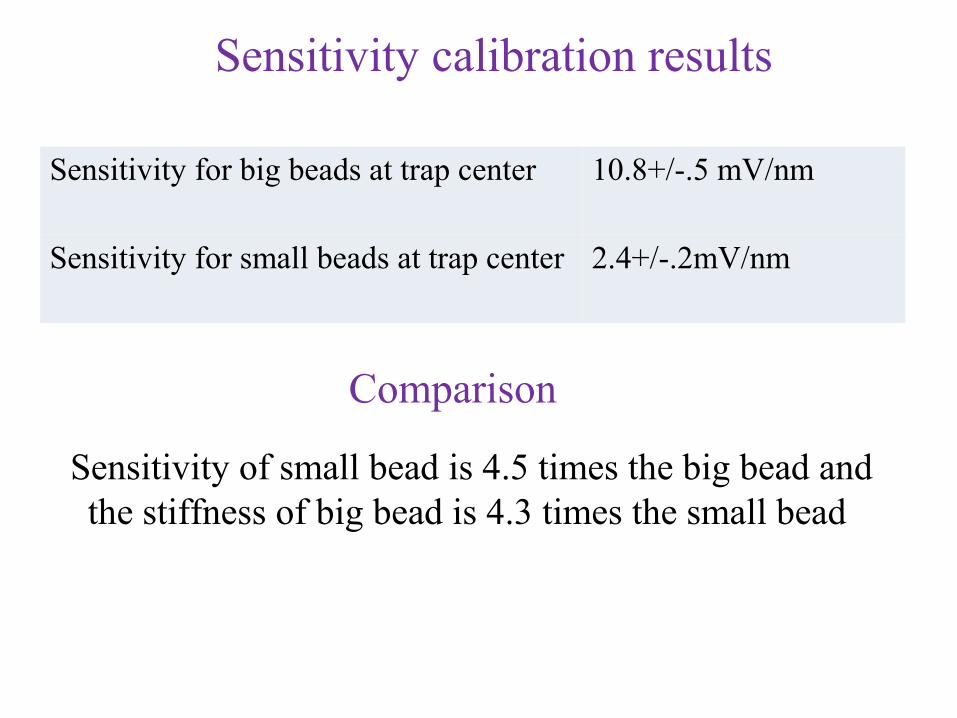
Sensitivity calibration results
Sensitivity of small bead is 4.5 times the big bead and the stiffness of big bead is 4.3 times the small bead
Comparison
Sensitivity for big beads at trap center 10.8+/-.5 mV/nm
Sensitivity for small beads at trap center 2.4+/-.2mV/nm
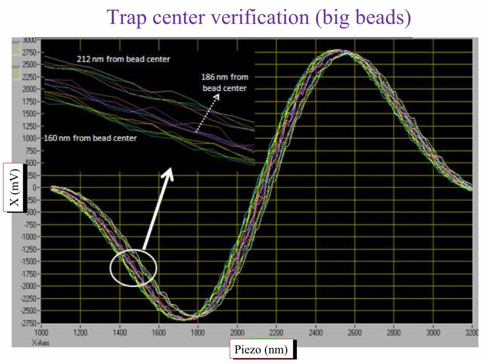
Trap center verification (big beads)X
(m
V)
X (
mV
)
Piezo (nm)Piezo (nm)
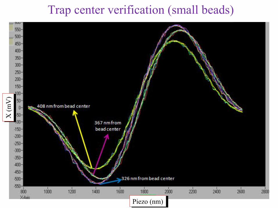
Trap center verification (small beads)X
(m
V)
X (
mV
)
Piezo (nm)Piezo (nm)
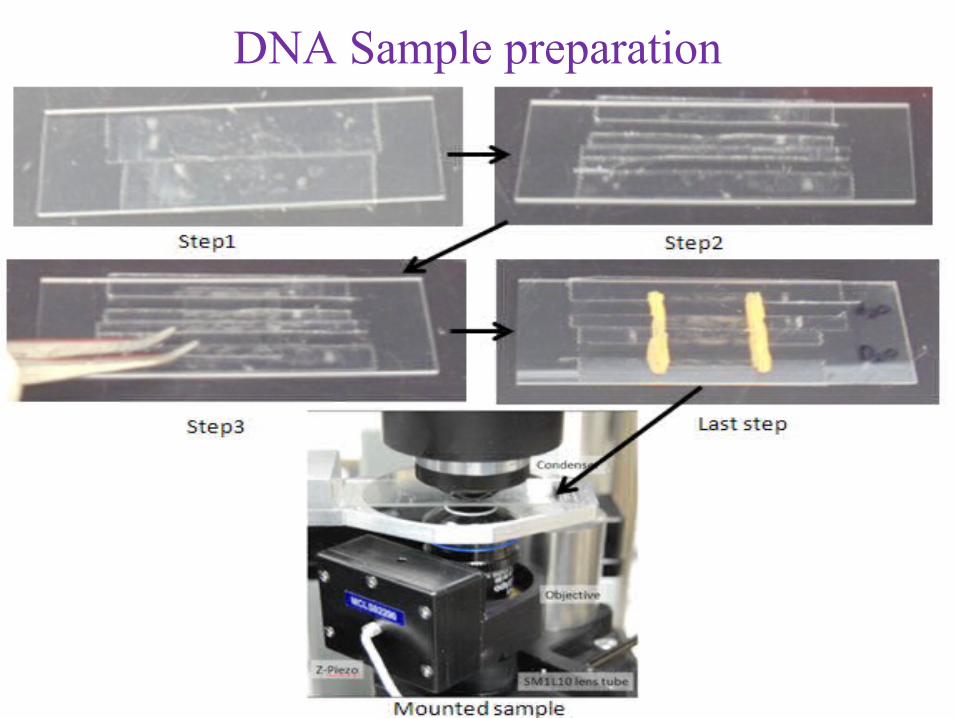
DNA Sample preparation
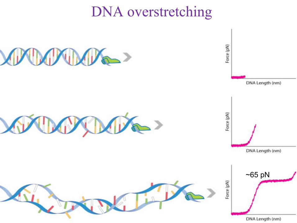
DNA overstretching
~65 pN
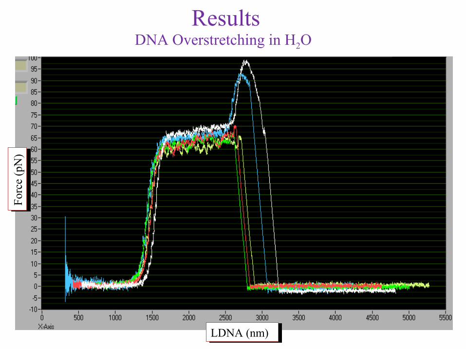
ResultsDNA Overstretching in H2O
Forc
e (p
N)
For
ce (
pN)
LDNA (nm)LDNA (nm)
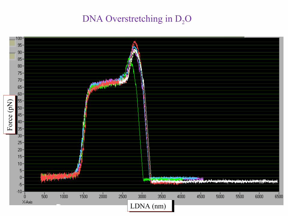
DNA Overstretching in D2OF
orce
(pN
)Fo
rce
(pN
)
LDNA (nm)LDNA (nm)
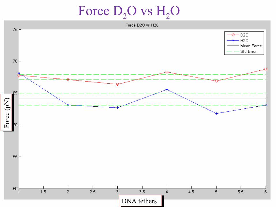
Force D2O vs H2OF
orce
(pN
)F
orce
(pN
)
DNA tethersDNA tethers
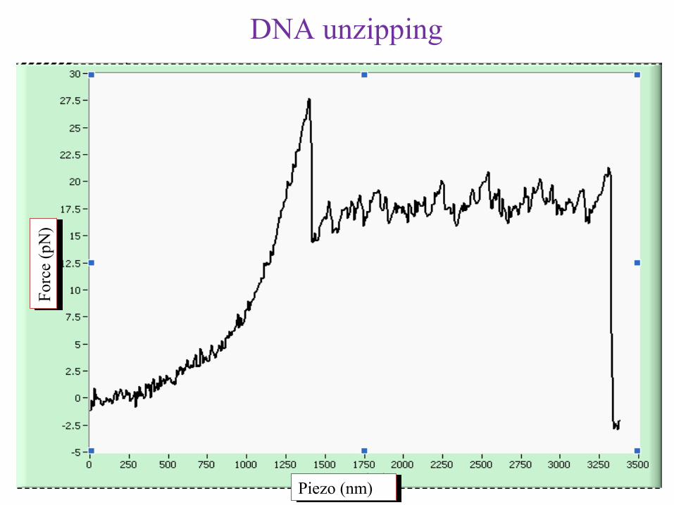
DNA unzippingF
orce
(pN
)F
orce
(pN
)
Piezo (nm)Piezo (nm)
Future work
• Automate Z piezo using camera to find the surface
• Automate Z lens and QPD controls
• DNA unzipping in D2O
• Investigate DNA protein interactions in H2O and D2O
• Develop touch screen controlled automation for optical tweezers

Thank You

Appendix: A
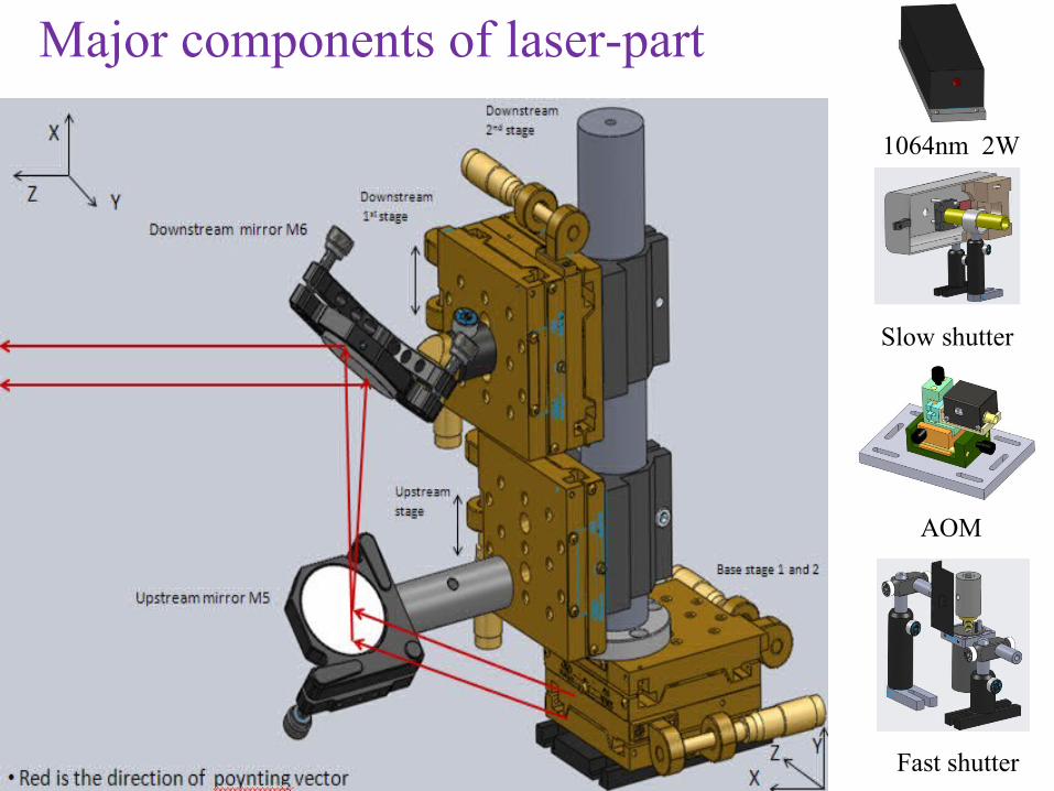
Major components of laser-part
1064nm 2W
Slow shutter
AOM
Fast shutter
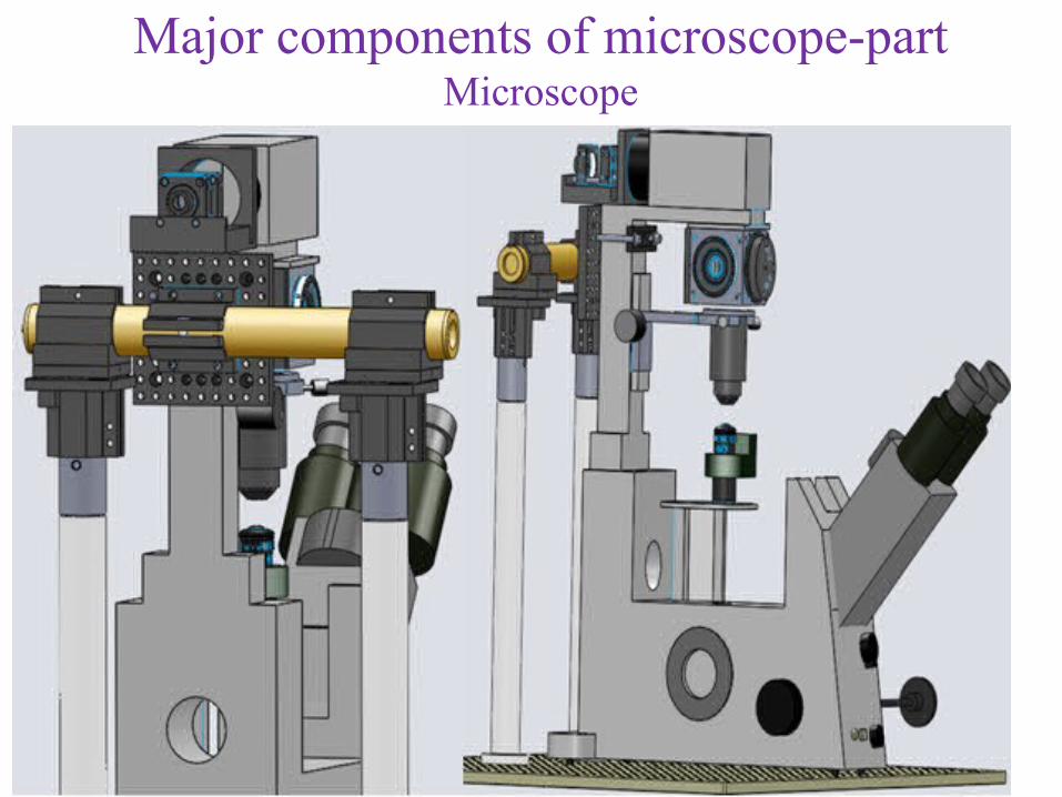
Major components of microscope-partMicroscope
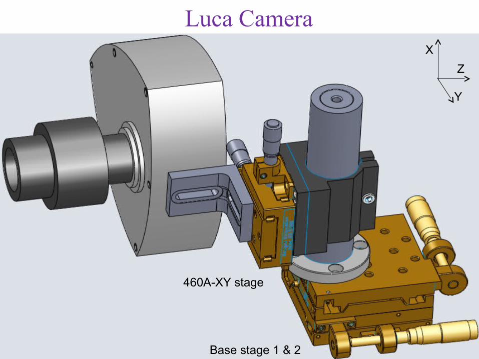
Luca Camera
Base stage 1 & 2
460A-XY stage
X
Y
Z
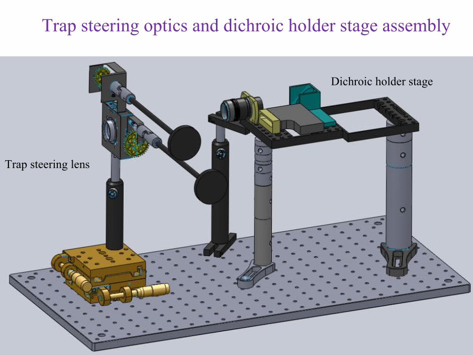
Trap steering optics and dichroic holder stage assembly
Trap steering lens
Dichroic holder stage
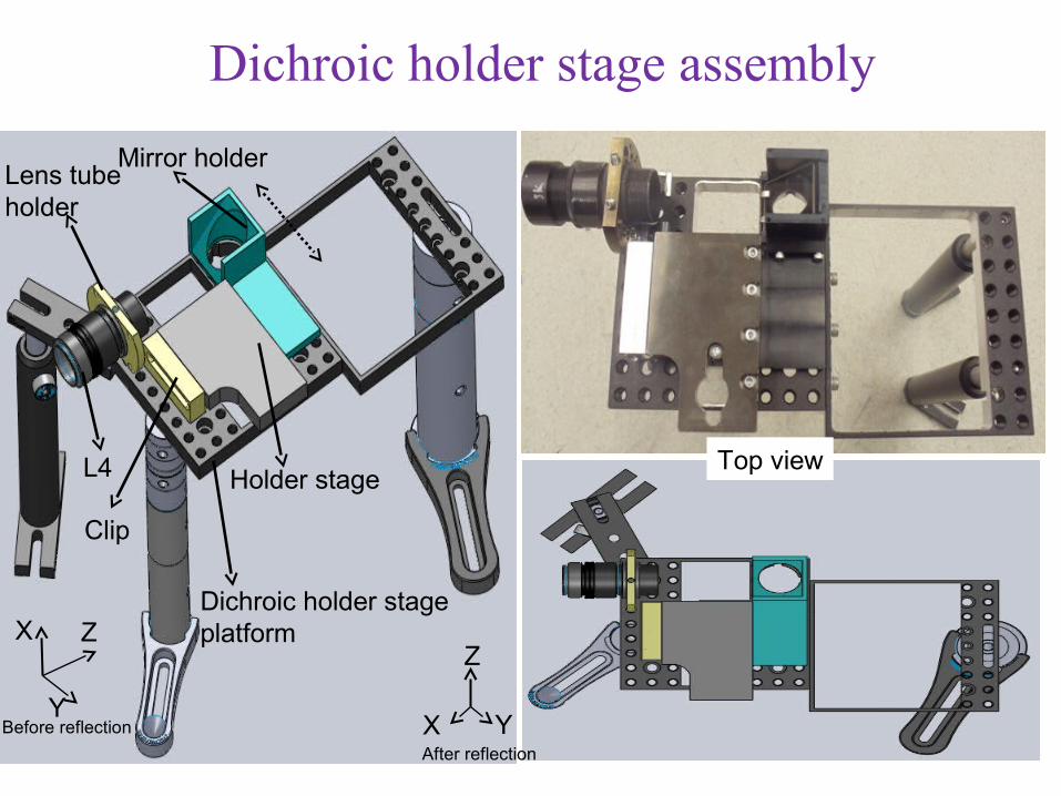
Holder stageL4
Mirror holderLens tube holder
Dichroic holder stage platform
Top view
Clip
X
Z
YAfter reflection
X Z
YBefore reflection
Dichroic holder stage assembly
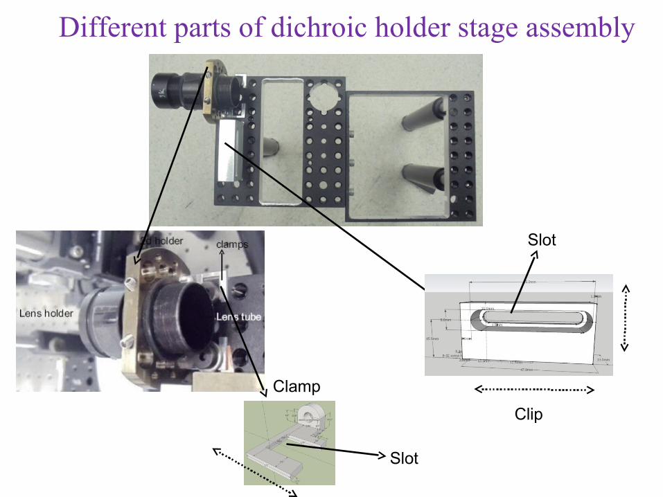
Slot
Slot
Clip
Clamp
Different parts of dichroic holder stage assembly
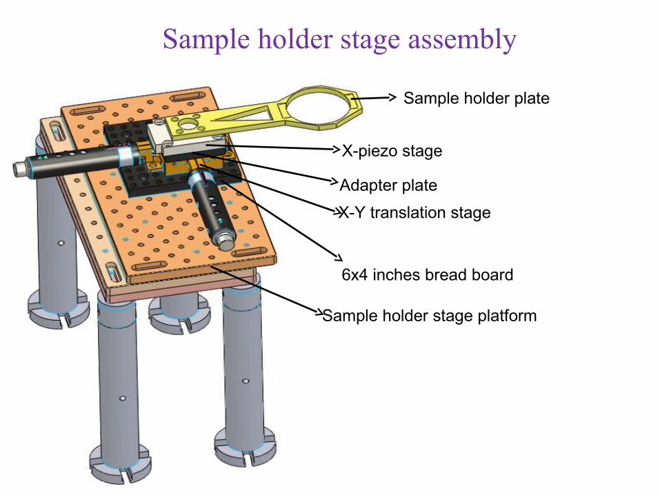
Sample holder plate
X-piezo stage
X-Y translation stage
Sample holder stage platform
Adapter plate
6x4 inches bread board
Sample holder stage assembly
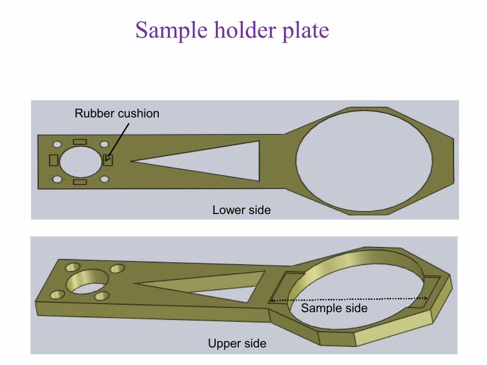
Sample holder plate
Upper side
Lower side
Sample side
Rubber cushion
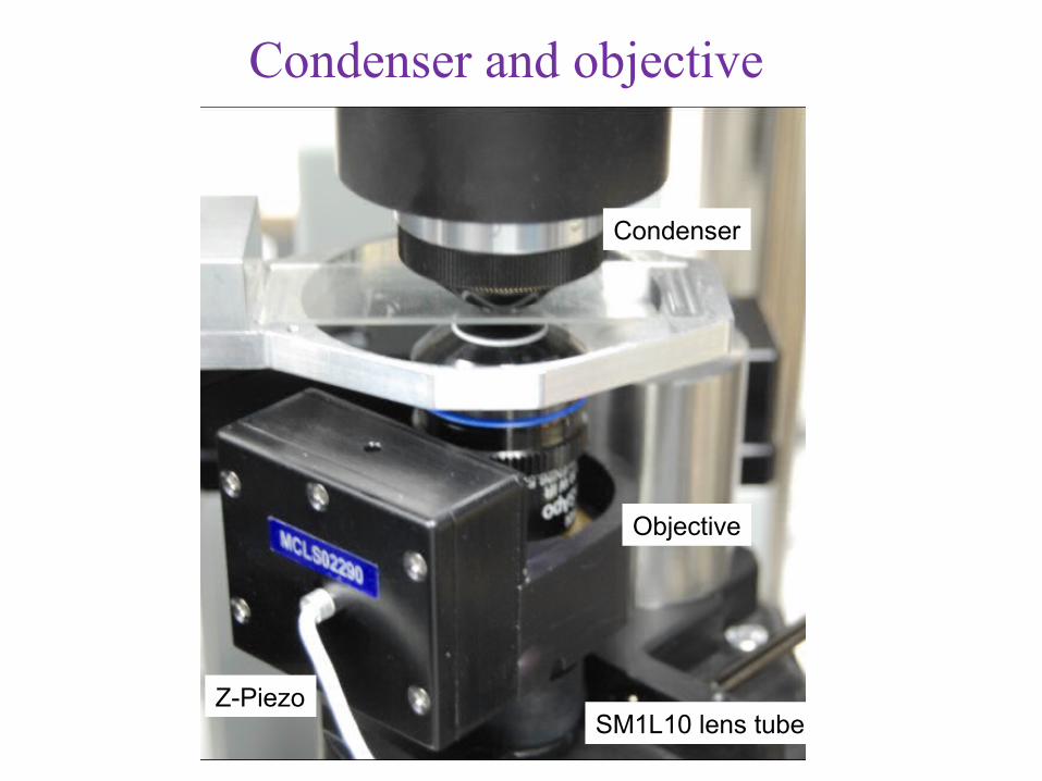
Objective
Condenser
Z-PiezoSM1L10 lens tube
Condenser and objective
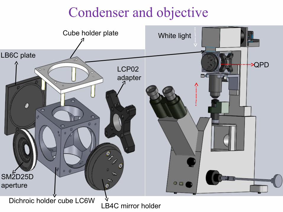
Cube holder plate White light
QPD
Dichroic holder cube LC6W
LB6C plate
SM2D25Daperture
LCP02adapter
LB4C mirror holder
Condenser and objective
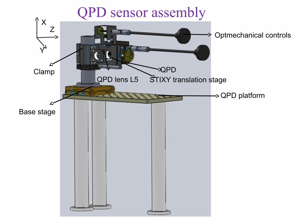
XZ
Y
QPD lens L5 STIXY translation stageQPD
QPD platform
Optmechanical controls
Base stage
Clamp
QPD sensor assembly
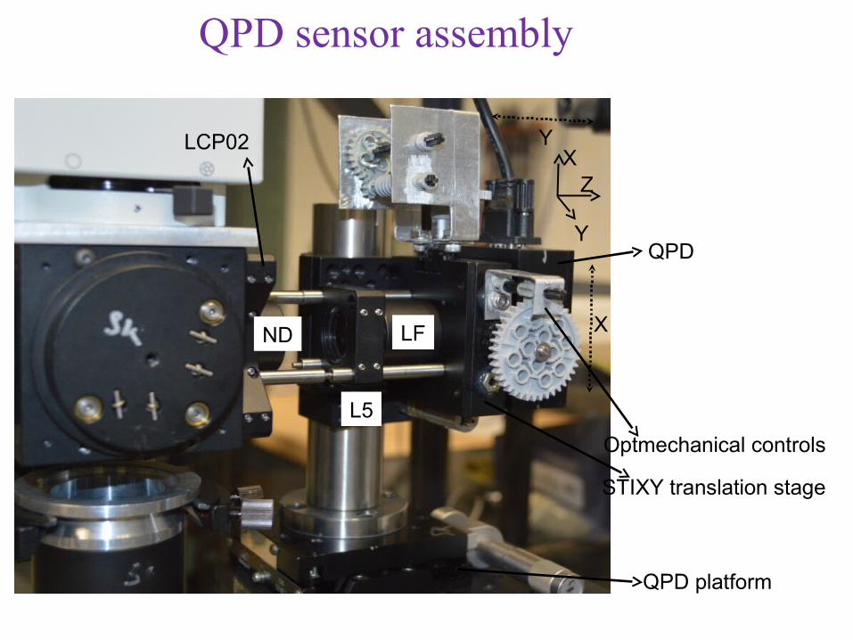
XZ
YQPD
Y
X
L5
STIXY translation stage
Optmechanical controls
LCP02
QPD platform
LFND
QPD sensor assembly
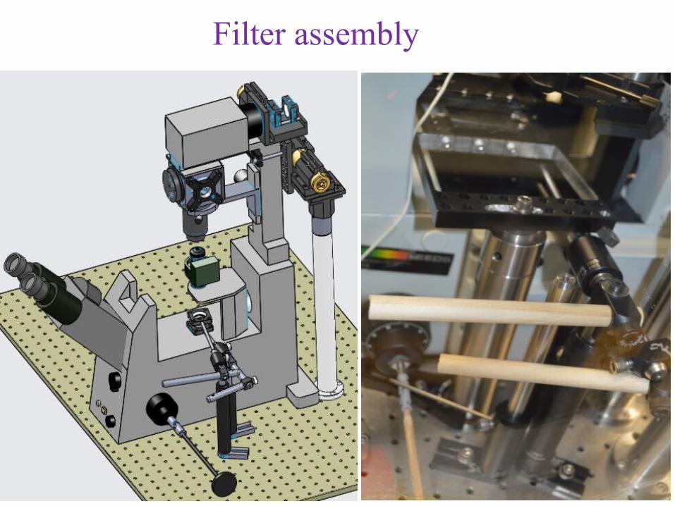
Filter assembly
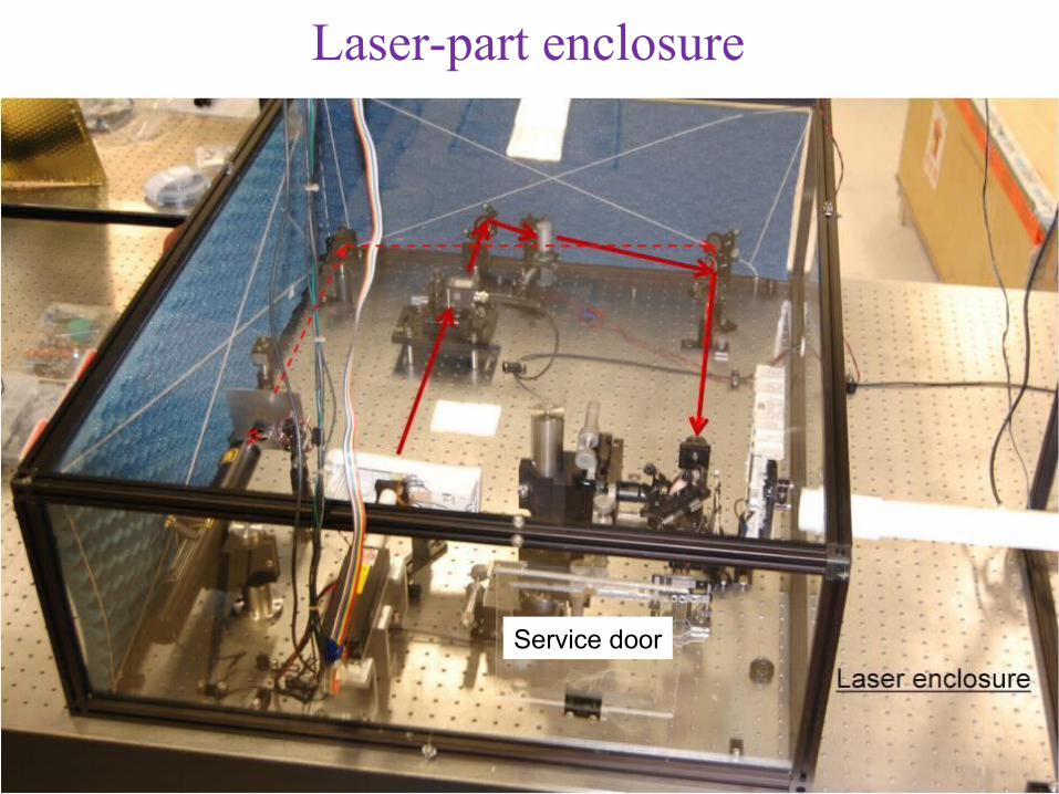
Service door
Laser-part enclosure
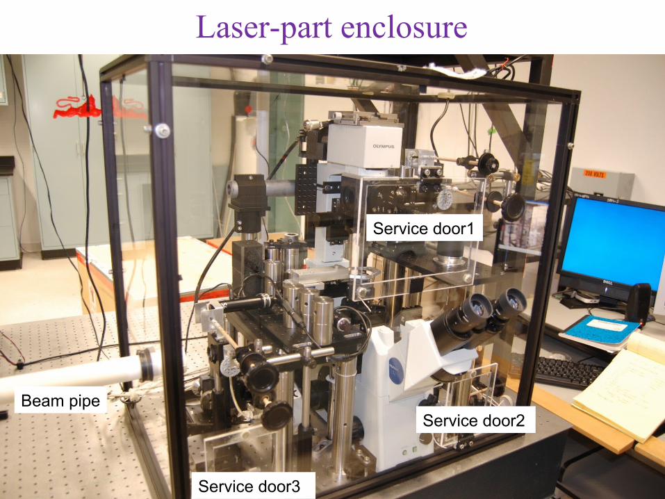
Service door1
Service door2
Service door3
Beam pipe
Laser-part enclosure
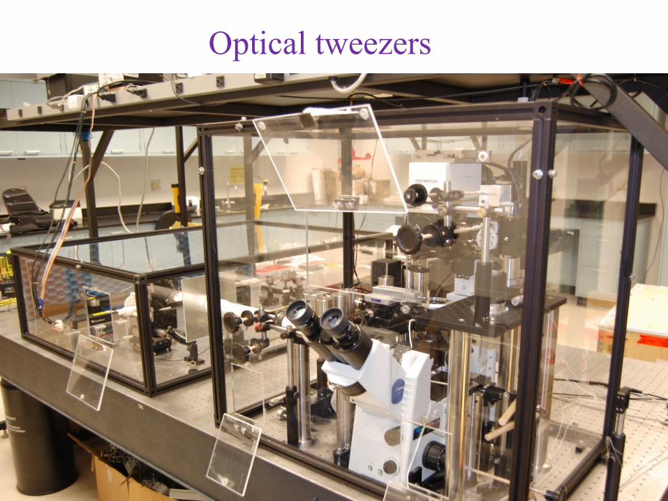
Optical tweezers