an analytical approach to estimate the compressive strength of...
TRANSCRIPT
AN ANALYTICAL APPROACH TO ESTIMATE THE COMPRESSIVESTRENGTH OF CARBON FIBRE REINFORCED PLASTICS
P.Y. Mechin, Univ. Bretagne Sud, IRDL CNRS 3744, F-5621 Lorient, France, [email protected]. Keryvin, Univ. Bretagne Sud, IRDL CNRS 3744, F-5621 Lorient, France,[email protected]. Grandidier, ISAE-ENSMA, Pprime CNRS 3346, F-86962 Futuroscope, France, [email protected]. Glehen, GSeaDesign , F-56270 Ploemeur, France, [email protected]
This study deals with the estimation of the compressive strength of carbon fibre reinforced plasticscomposites used in yacht racing. This property is one the key design parameters in marine engineering.The mechanism of fibre micro-buckling as well as a structural effect including the neighbouring plies ofthe unidirectional ply and the deformation gradient linked to the the mechanical loading are taken intoaccount to propose an analytical model for estimating this property. The parameters involved require anumber of experiments to characterise the microstructure at the level of components (fibre, matrix, ply)and the mechanical behaviour (elastoplasticity). Some of them can be estimated using a micro-mechanicalapproach. It is shown that estimations and experiments show good agreement on two cases: one with aconstant deformation gradient, the other one in pure compression. The paramount influence of the initialmisalignment of the fibre is highlighted.
NOMENCLATURE
Symbol Definition (unit)
UD Unidirectional tapeσfail
UD UD failure strength (MPa)σstab
UD Micro-buckling stability strength (MPa)σstru
UD Structural effect strength (MPa)σcrit
UD Combined effects of σstabUD and σstru
UD (MPa)EUD Axial compressive modulus of UD (MPa)GUD Shear modulus of UD (MPa)γyUD Critical shear strain (%)nUD Shape coefficient (-)Efl Longitudinal modulus of fiber (MPa)Eft Transverse modulus of fiber (MPa)Gflt In-plane shear modulus of fiber (MPa)νflt Major Poisson’s ratio of fiber (-)Em Young’s modulus of matrix (MPa)Gm Shear modulus of matrix (MPa)νm Poisson’s ratio of matrix (-)φ0 Initial misalignment of fiber (˚)Vf Volume fraction of fibers (%)eb Characteristic thickness of UD in model (mm)
1. INTRODUCTION
Carbon fiber Reinforced Polymers (CFRP) are widely used indifferent industrial areas (aeronautics, offshore engineering,
sustainable energies, marine industry. . . ) or specific customcases for racing (cars, yachts. . . ). They are used both for theirhigh specific stiffness and strength.
Yacht racing area has succeeded in using high perfor-mances composites through prestigious racing events: Amer-ica’s Cup, Volvo Ocean Race, or French competitions such asVendée Globe or Route du Rhum. . . Over the past 20 years,design offices such as GSEA-DESIGN (Lorient, France) havecontributed to the development of high performance racingyachts using CFRP such as BANQUE POPULAIRE V (cur-rently SPINDRIFT 2), GROUPAMA 3 (currently IDEC SPORT),SODEBO ULTIME or MACIF 100 (see Figure 1). Those fourboats have been the fastest around the world (JULES VERNETROPHY or single handed) with a current world record of 41days, at the average speed of 26.5 knots. For such racingyachts, CFRP covers about 80% of the structure’s weight.
From a structural point of view, all composites parts de-signed in marine area undergo compressive stresses (compres-sion, bending loadings). In the case of wings (mainsail wingor plane’s one), bending loads will induce one face in ten-sion, the other one in compression. On the other side, mastsundergo pure compression loadings due to the basement tune(docktune) to ensure a sufficient tension in cables at all times.Based on the observation that compressive strengths proper-ties are usually lower than tension ones [12], compressive fail-ure requires to be considered carefully. Therefore, being ableto predict properly the compressive strength is a main issuein marine yacht design. A good prediction of compressive
The Fourth International Conference on Innovation in High Performance Sailing Yachts, Lorient, France
INNOV'SAIL 2017 183

Figure 1: Maxi 100’ Macif (Credits Jean-Marie Liot).
strength will provide accurate design of structures.Compressive failure has been the topic of numerous stud-
ies over the past 50 years. In term of predictive modelling,several approaches have been suggested ([25, 3, 9, 8, 7]). Thewidely accepted scenario leading to failure consists in takinginto account the out-of-plane displacement of the fiber (dis-alignment) constrained by the elasto-plastic matrix stiffness(cf. Figure 2).
When the compressive load (σ∞, labelled σ in Fig. 2)increases, the initial misalignment φ0 of the fiber increases.The matrix contains this propensity of the fiber to buckle.This is done first by its elastic stiffness, then, after yield-ing, by its plasticity. The matrix undergoes a huge shearing,maximum at the location of maximum misalignment. Thus,bending of the fiber occurs, generating a deformation gradientthrough the fiber’s section. Different scenarios of failure canthen occur: namely fiber breakage, matrix failure or interfacedebonding. It usually occurs in the fiber (locally in tension)with a specific failure mechanism named kinking (detailed byArgon [3]).
Plastic shearing of matrix
Fibers failure in tension
Figure 2: Definition of parameters and geometry involved inthe formation of a kinking band during compression, from[14].
Numerous models use this specific relationship between themacroscopic compressive stress (σ∞) on the UD and localshearing of UD due to the misalignment of the fiber. Rosen[25] suggested an elastic linear relationship. This model sug-gests that compressive failure only depends only on fiber vol-ume fraction and matrix’s elastic stiffness. A GARTEUR ex-perimental programme [27] showed this model to be wrong.According to literature, the compressive strength of high mod-ulus fiber composites is lower than the one of high strengthfiber [12]. Rosen’s approach [25] approach predicts overesti-mated compressive strengths in numerous cases.
Argon [3] later suggested to take into account the initialmisalignment as well a relationship between shear stress andshear strain in matrix perfectly plastic. This relation hasbeen improved by Budiansky and Fleck [9] with a non lin-ear Ramberg-Osgood type-behaviour incorporating, elastic-ity, yield, plasticity and hardening. The model calculates themaximum compressive strength before the instability appears(the fiber buckling). Finally, the difference between all thosemodels is their ability to model the behaviour of matrix (frompure elastic to elasto-plastic). According to experimental re-sults performed using flexural tests, the previous model pro-vided lower results than experimental ones. A structural ef-fect was then introduced by [11, 13, 14]. This structural ef-fect contributes to take into account both the effect of the de-formation gradient due to flexural test and the influence ofneighbouring plies (in terms of stiffness).
The purpose of this study is to validate this complete modelincorporating the micro-buckling mechanism and the struc-tural effect. We first recall the salient features of this model.We will then present experimental results on a CFRP speci-men by performing compression tests (that does not exhibitthe deformation gradient contribution) and bending tests. Thevalues of the compressive strengths in both cases will com-pared to the analytical model. The latter requires some keyshear properties of UD, usually extracted form tension testson [+/-45◦] stackings. We will present a numerical micro-mechanical tool to estimate these properties.
2. THEORETICAL BACKGROUND
2.1 MICRO-BUCKLING OF FIBER
Budiansky and Fleck [8] chose to model the non-linear shearbehaviour of UD γ (shear strain) vs. τ (shear stress) by usinga Ramberg-Osgood (RO) description (Eq. (1)) using three pa-rameters: γyUD, GUD and nUD (τyUD is a shear stress defined byτyUD = GUD × γyUD)). The coefficient 3
7 is specific to a choicemade in [8].
γ
γyUD=
τ
τyUD+
3
7× (
τ
τyUD)nUD (1)
The compressive strength, referred to as σstabUD calculated us-
ing [8] model (Eq. (2)) is defined as the maximum stress be-fore the instability of the fiber appears. According to model,the larger the initial misalignment, the lower the compressivestrength of UD.
The Fourth International Conference on Innovation in High Performance Sailing Yachts, Lorient, France
INNOV'SAIL 2017 184
σstabUD =
GUD
1 + nUD
(3
7
) 1
nUD(φ0/γ
yUD
nUD − 1
)(nUD − 1
nUD
) (2)
Results of the model have been tested with both compres-sive and torsion loadings on tubes with thin layer ([21]). Dueto the multi-axial loading in experiments, comparisons be-tween estimations and experiments are rather uneasy.
2.2 STRUCTURAL EFFECT
The structural effect is a term grouping mechanisms that donot depend on the UD scale but rather at a larger scale, theone of the laminate. Two of them are considered here: thestiffness of the neighbouring plies and the presence of a de-formation gradient. Some researchers [1, 22] observed thatthe compressive strength is lower for laminates with a largernumber of consecutive UD (no sub-sequence) with the samefiber/matrix couple. Therefore, they suggested a relationshipbetween the compressive strength and the number of consec-utive UD. Moreover, Berbineau et al. [7] made equivalent ob-servations with neighbouring off-axis plies. They observedthat the compressive strength decreases when off-axis pliesangle increases (the couple fiber/matrix stays unchanged).They suggested a correlation between the stiffness of neigh-bouring plies and compressive strength.
According to literature [2, 15], the experimental compres-sive strength is subjected to large differences between twomain testing methods: a direct method that is axial compres-sive test [4] and non-direct methods such as a flexural test (forexample 4 points flexural test - [6]). Higher failure strains areobtained using flexural testing. Axial compressive testing pro-vides lower results and a significant standard deviation. Themain difference between these two methods is the presence ofa (constant) deformation gradient through the thickness of thelaminate.
Several possibilities to explain such differences have beenstudied. The works of Ref. [11, 13] showed, by studying thestability of the fiber, that increasing the stiffness of neighbour-ing plies or reducing the thickness of UD contribute in delay-ing the formation of the kinking-band mechanism. Moreover,Drapier et al. [10] detailed the effect of a deformation gradi-ent through a flexural loading.They showed that a deformationgradient changes the compressive failure mode and locally in-creases the stability of fiber.
All these observation on structural effects have been exper-imentally detailed and compared in [14] with the proposal ofan analytical model (Eq. (3)) taking into account both themicro-buckling mechanism from [8] and the structural effectfrom [13]:
σcritUD = σstab
UD + 2 rgfπ
eb
√EmEf
1− ν2mVf (1− Vf ) (3)
where rgf is the gyration radius of the fiber, Em theYoung’s modulus of the matrix, Ef the longitudinal modulusof the fiber, νm the Poisson’s ratio of the matrix, Vf the fiber
volume fraction and eb the thickness of UD involved in theinstability (a fraction of the total thickness of UD, see below).
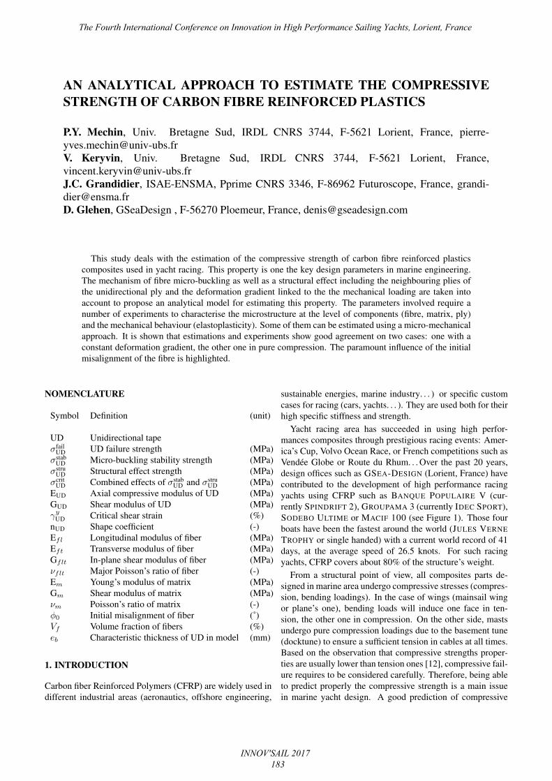
Grandidier et al. [14] performed three points bending [5]with different UD thicknesses and different UD positions(with the same fiber/matrix couple). A critical thickness (eb)was defined to depend both on the UD thickness (effectivenumber of consecutive UD) and the UD position (effect ofneighbouring plies and deformation gradient). A schematicsof some cases is shown in Figure 3. For instance, for a UDlayer containing the neutral axis (fig. 3 - a), only the part incompression is considered for critical thickness (ec), while forsub-stack laminate (b), ec is equivalent to the thickness of twoouter UD plies subjected to pure compression (deformationgradient is neglected for small thickness).
For full UD stackings, due to the instability mode which islocated near to free edge (due to deformation gradient), onlya reduced part of the UDs is considered to be contributive tocompression failure. In this way, characteristic thickness isconsidered as eb = 0.4×ec. On the other hand, in case of sub-stacking, characteristic thickness is considered as eb = ec
Bending
ec
(a)
Bendingec
(b)
Figure 3: Effect of critical thickness (ec, eb) according to de-formation gradient considered: (a) for [0]20 laminate, (b) for[02,±45˚, 02, ±45˚, 02]S laminate (Issue from [14]).
3. MATERIALS AND METHODS
3.1 MATERIALS
Three main carbon fibres types can be listed: high strength(HS) carbon fibres (as T300, T700 from TORAY or MR60,TR50 from MITSUBISHI) with a longitudinal modulus of ∼260 GPa, intermediate modulus (IM) carbon fibres (T800,M30S from TORAY) with longitudinal modulus of∼ 290 GPaand high modulus (HM) carbon fibres (M40J, M46J fromTORAY or HR40, HS40 from MITSUBISHI) with longitudi-nal modulus of ∼ 390-460 GPa. All those carbon fibres arebased on PAN precursors. Stiffer carbon fibres exist usingpitch precursors (as Ke637-12 from DIALED - MITSUBISHI).Those fibres will be not considered in this study. Both HS andIM carbon fibres are widely used for aeronautics applications.The study is getting focused on HM carbon fibres HS40 asUD plies and HR40 as off-axis plies.
The associated matrix is an epoxy resin system producedby SAFRAN STRUCTIL (R367-2). This epoxy resin systemis widely used in marine applications. This is a resin with acuring system around 110˚C, lower than 180˚C aeronauticalcurrent epoxy systems. The pre-impregnated CFRP supplierwas able to produce a block of matrix (100×100×20 mm3).To ensure that reticulation of the polymer is exactly the same
The Fourth International Conference on Innovation in High Performance Sailing Yachts, Lorient, France
INNOV'SAIL 2017 185
at all locations in the block, the control of quality using Differ-ential Scanning Calorimetry (DSC) experiments is performed.DSC is used to measure the glass transition temperature (Tg)that defines quality of reticulation. No difference betweensamples from the skin or the core of the matrix block has beenfound.
Two following stacking sequences were used for the com-posites:
• A monolithic one: according to a database of marine de-sign, a [±45˚, 07˚, ±45˚, 07˚, ±45˚, 07˚, -45˚]S stackingis considered. The 0˚ plies (UD, 300 g/m2) are made outof HS40 fibers while off-axis plies (±45˚, 150 gr/m2) aremade out of HR40 fibers.
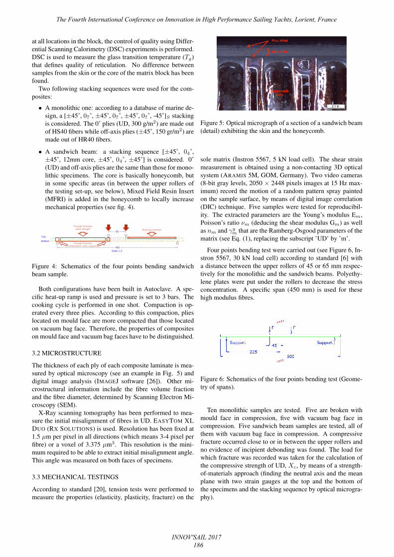
• A sandwich beam: a stacking sequence [±45˚, 04˚,±45˚, 12mm core, ±45˚, 04˚, ±45˚] is considered. 0˚(UD) and off-axis plies are the same than those for mono-lithic specimens. The core is basically honeycomb, butin some specific areas (in between the upper rollers ofthe testing set-up, see below), Mixed Field Resin Insert(MFRI) is added in the honeycomb to locally increasemechanical properties (see fig. 4).
���
��
������
��
��� ����
Through thickness compression under supports
Skin/core interfaceThrough thickness
shear strength
Figure 4: Schematics of the four points bending sandwichbeam sample.
Both configurations have been built in Autoclave. A spe-cific heat-up ramp is used and pressure is set to 3 bars. Thecooking cycle is performed in one shot. Compaction is op-erated every three plies. According to this compaction, plieslocated on mould face are more compacted that those locatedon vacuum bag face. Therefore, the properties of compositeson mould face and vacuum bag faces have to be distinguished.
3.2 MICROSTRUCTURE
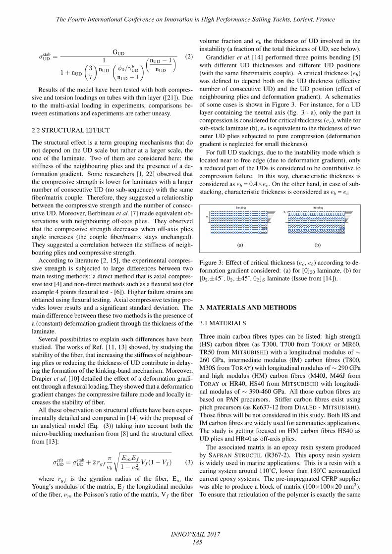
The thickness of each ply of each composite laminate is mea-sured by optical microscopy (see an example in Fig. 5) anddigital image analysis (IMAGEJ software [26]). Other mi-crostructural information include the fibre volume fractionand the fibre diameter, determined by Scanning Electron Mi-croscopy (SEM).
X-Ray scanning tomography has been performed to mea-sure the initial misalignment of fibres in UD. EASYTOM XLDUO (RX SOLUTIONS) is used. Resolution has been fixed at1.5 µm per pixel in all directions (which means 3-4 pixel perfibre) or a voxel of 3.375 µm3. This resolution is the mini-mum required to be able to extract initial misalignment angle.This angle was measured on both faces of specimens.
3.3 MECHANICAL TESTINGS
According to standard [20], tension tests were performed tomeasure the properties (elasticity, plasticity, fracture) on the
Figure 5: Optical micrograph of a section of a sandwich beam(detail) exhibiting the skin and the honeycomb.
sole matrix (Instron 5567, 5 kN load cell). The shear strainmeasurement is obtained using a non-contacting 3D opticalsystem (ARAMIS 5M, GOM, Germany). Two video cameras(8-bit gray levels, 2050 × 2448 pixels images at 15 Hz max-imum) record the motion of a random pattern spray paintedon the sample surface, by means of digital image correlation(DIC) technique. Five samples were tested for reproducibil-ity. The extracted parameters are the Young’s modulus Em,Poisson’s ratio νm (deducing the shear modulus Gm) as wellas nm and γym that are the Ramberg-Osgood parameters of thematrix (see Eq. (1), replacing the subscript ’UD’ by ’m’.
Four points bending test were carried out (see Figure 6, In-stron 5567, 30 kN load cell) according to standard [6] witha distance between the upper rollers of 45 or 65 mm respec-tively for the monolithic and the sandwich beams. Polyethy-lene plates were put under the rollers to decrease the stressconcentration. A specific span (450 mm) is used for thesehigh modulus fibres.
Figure 6: Schematics of the four points bending test (Geome-try of spans).
Ten monolithic samples are tested. Five are broken withmould face in compression, five with vacuum bag face incompression. Five sandwich beam samples are tested, all ofthem with vacuum bag face in compression. A compressivefracture occurred close to or in between the upper rollers andno evidence of incipient debonding was found. The load forwhich fracture was recorded was taken for the calculation ofthe compressive strength of UD, Xc, by means of a strength-of-materials approach (finding the neutral axis and the meanplane with two strain gauges at the top and the bottom ofthe specimens and the stacking sequence by optical microgra-phy).
The Fourth International Conference on Innovation in High Performance Sailing Yachts, Lorient, France
INNOV'SAIL 2017 186
4. NUMERICAL SIMULATION
4.1 LAMINATE MODEL
A finite element model (FEM) of a sandwich beam sampleis established using Abaqus 6.14TM(fig. 7). This model ismeshed using 2D Shell elements (Kirchoff shell theory) tomodel the skins. The honeycomb part is meshed using 2DShell elements to fully mesh the cells. The MFRI parts aremeshed using 3D linear Solid elements. The contact betweencylinders, the polyethylene plates and the skins is taken asfrictionless. Due to compressive stresses both in the skins(bending moment) and in the honeycomb (shear force), thestability of each material part has to be checked.
Figure 7: View of FEM model (sandwich beam sample) sub-jected to four points bending test.
Indeed, compressed skins may buckle at lower stresses thanthe compressive failure strength due to the thin layer of skinand its associated buckling mode. Therefore, a RIKS methodis used to calculate the different buckling modes of the struc-ture and the associated level of loading at which they appear.According to FEM results, failure in compressive laminateskin will occur in compression before the local instabilityarises.
Another FEM is established for the monolithic stacking toextract compressive stresses in UDs. Each layer of compos-ite is meshed using shell elements. Due to the thickness, nobuckling mode calculation is required.
4.2 MICRO-MECHANICAL MODEL
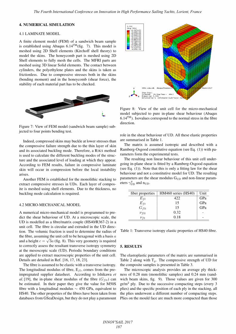
A numerical micro-mechanical model is programmed to pre-dict the shear behaviour of UD. At a microscopic scale, theUD is modelled as a fibre/matrix couple (HS40/R367-2) in aunit cell. The fibre is circular and extruded in the UD direc-tion. The volumic fraction is used to determine the radius ofthe fibre, assuming the unit cell to be hexagonal with a basis aand a height c =
√3a (fig. 8). This very geometry is required
to correctly assess the resultant transverse isotropy symmetryat the mesoscopic scale (UD). Periodic boundary conditionsare applied to extract macroscopic properties of the unit cell.Details are detailed in Ref. [16, 17, 18, 23].
The fibre is assumed to be elastic with a transverse isotropy.The longitudinal modulus of fibre, Efl, comes from the pre-impregnated supplier datasheet. According to Ishikawa etal. [19], the in-plane shear modulus of the fibre (Gflt) canbe estimated. In their paper they give the value for M50Sfibre with a longitudinal modulus ∼ 450 GPa, equivalent toHS40. The other properties of the fibres have been taken fromdatabases from GSeaDesign, but they do not play a paramount
Figure 8: View of the unit cell for the micro-mechanicalmodel subjected to pure in-plane shear behaviour (Abaqus6.14TM). Isovalues correspond to the normal stress in the fibredirection.
role in the shear behaviour of UD. All these elastic propertiesare summarised in Table 1.
The matrix is assumed isotropic and described with aRamberg-Osgood constitutive equation (see Eq. (1)) with pa-rameters form the experimental tests.
The resulting non linear behaviour of this unit cell under-going in-plane shear is fitted by a Ramberg-Osgood equation(see Eq. (1)). Note that this is only a fitting law for the shearbehaviour and not a constitutive model for UD. The resultingparameters are the shear modulus GUD and non-linear param-eters γyUD and nUD.
fiber properties HM460 series (HS40) UnitEfl 422 GPaEft 15 GPaGflt 15 GPaνflt 0.32 -νft 0.18 -
Table 1: Transverse isotropy elastic properties of HS40 fibre.
5. RESULTS
The elastoplastic parameters of the matrix are summarised inTable 2 along with Tg . The compressive strength of UD forthe composite samples is presented in Table 3.
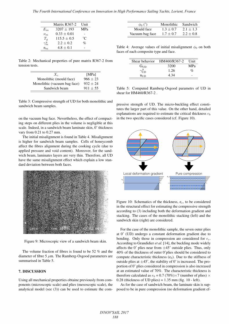
The microscopic analysis provides an average ply thick-ness of 0.28 mm (monolithic samples) and 0.24 mm (sand-wich beam skins, fig. 9). Those values are given for 300gr/m2 ply. Due to the successive compacting steps (every 3plies) and the specific position of each ply in the stacking, allthe plies underwent a different number of compacting steps.Plies on the mould face are much more compacted than those
The Fourth International Conference on Innovation in High Performance Sailing Yachts, Lorient, France
INNOV'SAIL 2017 187
Matrix R367-2 UnitEm 3207 ± 193 MPaνm 0.33 ± 0.01 -Tg 115.5 ± 0.5 ˚Cγym 2.2 ± 0.2 %nm 4.8 ± 0.1 -
Table 2: Mechanical properties of pure matrix R367-2 fromtension tests.
Xc [MPa]Monolithic (mould face) 966 ± 23
Monolithic (vacuum bag face) 932 ± 24Sandwich beam 911 ± 55
Table 3: Compressive strength of UD for both monolithic andsandwich beam samples.
on the vacuum bag face. Nevertheless, the effect of compact-ing steps on different plies in the volume is negligible at thisscale. Indeed, in a sandwich beam laminate skin, 0˚ thicknessvary from 0.21 to 0.27 mm.
The initial misalignment is found in Table 4. Misalignmentis higher for sandwich beam samples. Cells of honeycombaffect the fibres alignment during the cooking cycle (due toapplied pressure and void content). Moreover, for the sand-wich beam, laminates layers are very thin. Therefore, all UDhave the same misalignment effect which explain a low stan-dard deviation between both faces.
Figure 9: Microscopic view of a sandwich beam skin.
The volume fraction of fibres is found to be 52 % and thediameter of fibre 5 µm. The Ramberg-Osgood parameters aresummarised in Table 5.
7. DISCUSSION
Using all mechanical properties obtaine previously from com-ponents (microscopic scale) and plies (mesoscopic scale), theanalytical model (see (3)) can be used to estimate the com-
φ0 (˚) Monolithic SandwichMould face 1.3 ± 0.7 2.1 ± 1.3
Vacuum bag face 1.7 ± 0.7 2.2 ± 0.8
Table 4: Average values of initial misalignment φ0 on bothfaces of each composite type and face.
Shear behavior HM460/R367-2 UnitGUD 3200 MPaγyUD 1.26 %nUD 4.34 -
Table 5: Computed Ramberg-Osgood parametrs of UD inshear for HM460/R367-2 .
pressive strength of UD. The micro-buckling effect consti-tutes the larger part of this value. On the other hand, detailedexplanations are required to estimate the critical thickness ebin the two specific cases considered (cf. Figure 10).
Bending
ec
Bendingec
Local deformation gradient Pure compression
Figure 10: Schematics of the thickness, ec, to be consideredin the structural effect for estimating the compressive strengthaccording to (3) including both the deformation gradient andstacking. The cases of the monolithic stacking (left) and thesandwich skin (right) are considered.
For the case of the monolithic sample, the seven outer pliesat 0˚ (UD) undergo a constant deformation gradient due tobending. Only those in compression are considered for ec.According to Grandidier et al. [14], the buckling mode widelyaffects the 0˚ plies near from ±45˚ outside plies. Thus, only40% of the thickness of outer 0˚plies should be considered tocompute characteristic thickness (eb). Due to the stiffness ofoutside plies at ±45˚, the stability of 0˚ is increased. The pro-portion of 0˚ plies considered in compression is also increasedat an estimated value of 70%. The characteristic thickness istherefore calculated as eb = 0.7 (70%)×7 (number of plies) ×0.28 (thickness of UD plies) = 1.35 mm (fig. 10 - left).
As for the case of sandwich beam, the laminate skin is sup-posed to be in pure compression (no deformation gradient ef-
The Fourth International Conference on Innovation in High Performance Sailing Yachts, Lorient, France
INNOV'SAIL 2017 188
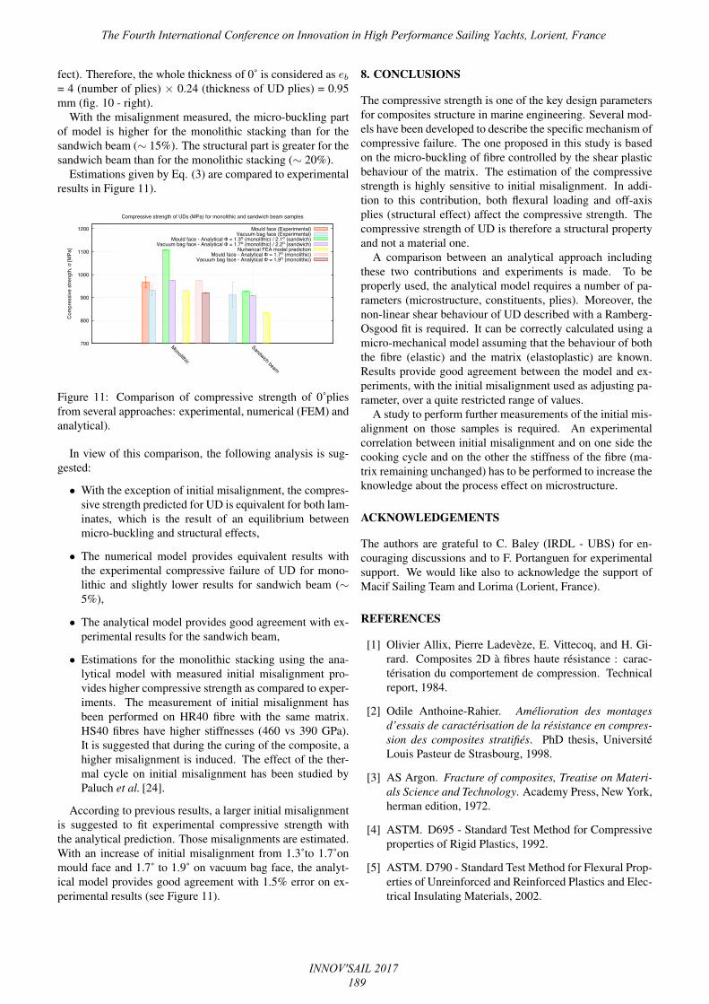
fect). Therefore, the whole thickness of 0˚ is considered as eb= 4 (number of plies) × 0.24 (thickness of UD plies) = 0.95mm (fig. 10 - right).
With the misalignment measured, the micro-buckling partof model is higher for the monolithic stacking than for thesandwich beam (∼ 15%). The structural part is greater for thesandwich beam than for the monolithic stacking (∼ 20%).
Estimations given by Eq. (3) are compared to experimentalresults in Figure 11).
����
����
����
�����
�����
�����
����������
��������
�����
�����������
������������
������
��������������������������������������������������������������������������
�������������������������������������������������������
�����������������������������������������������������������������������������������������������������������������������������������
���������������������������������������������������������������������������
��������������������������������������������������
Figure 11: Comparison of compressive strength of 0˚pliesfrom several approaches: experimental, numerical (FEM) andanalytical).
In view of this comparison, the following analysis is sug-gested:
• With the exception of initial misalignment, the compres-sive strength predicted for UD is equivalent for both lam-inates, which is the result of an equilibrium betweenmicro-buckling and structural effects,
• The numerical model provides equivalent results withthe experimental compressive failure of UD for mono-lithic and slightly lower results for sandwich beam (∼5%),
• The analytical model provides good agreement with ex-perimental results for the sandwich beam,
• Estimations for the monolithic stacking using the ana-lytical model with measured initial misalignment pro-vides higher compressive strength as compared to exper-iments. The measurement of initial misalignment hasbeen performed on HR40 fibre with the same matrix.HS40 fibres have higher stiffnesses (460 vs 390 GPa).It is suggested that during the curing of the composite, ahigher misalignment is induced. The effect of the ther-mal cycle on initial misalignment has been studied byPaluch et al. [24].
According to previous results, a larger initial misalignmentis suggested to fit experimental compressive strength withthe analytical prediction. Those misalignments are estimated.With an increase of initial misalignment from 1.3˚to 1.7˚onmould face and 1.7˚ to 1.9˚ on vacuum bag face, the analyt-ical model provides good agreement with 1.5% error on ex-perimental results (see Figure 11).
8. CONCLUSIONS
The compressive strength is one of the key design parametersfor composites structure in marine engineering. Several mod-els have been developed to describe the specific mechanism ofcompressive failure. The one proposed in this study is basedon the micro-buckling of fibre controlled by the shear plasticbehaviour of the matrix. The estimation of the compressivestrength is highly sensitive to initial misalignment. In addi-tion to this contribution, both flexural loading and off-axisplies (structural effect) affect the compressive strength. Thecompressive strength of UD is therefore a structural propertyand not a material one.
A comparison between an analytical approach includingthese two contributions and experiments is made. To beproperly used, the analytical model requires a number of pa-rameters (microstructure, constituents, plies). Moreover, thenon-linear shear behaviour of UD described with a Ramberg-Osgood fit is required. It can be correctly calculated using amicro-mechanical model assuming that the behaviour of boththe fibre (elastic) and the matrix (elastoplastic) are known.Results provide good agreement between the model and ex-periments, with the initial misalignment used as adjusting pa-rameter, over a quite restricted range of values.
A study to perform further measurements of the initial mis-alignment on those samples is required. An experimentalcorrelation between initial misalignment and on one side thecooking cycle and on the other the stiffness of the fibre (ma-trix remaining unchanged) has to be performed to increase theknowledge about the process effect on microstructure.
ACKNOWLEDGEMENTS
The authors are grateful to C. Baley (IRDL - UBS) for en-couraging discussions and to F. Portanguen for experimentalsupport. We would like also to acknowledge the support ofMacif Sailing Team and Lorima (Lorient, France).
REFERENCES
[1] Olivier Allix, Pierre Ladevèze, E. Vittecoq, and H. Gi-rard. Composites 2D à fibres haute résistance : carac-térisation du comportement de compression. Technicalreport, 1984.
[2] Odile Anthoine-Rahier. Amélioration des montagesd’essais de caractérisation de la résistance en compres-sion des composites stratifiés. PhD thesis, UniversitéLouis Pasteur de Strasbourg, 1998.
[3] AS Argon. Fracture of composites, Treatise on Materi-als Science and Technology. Academy Press, New York,herman edition, 1972.
[4] ASTM. D695 - Standard Test Method for Compressiveproperties of Rigid Plastics, 1992.
[5] ASTM. D790 - Standard Test Method for Flexural Prop-erties of Unreinforced and Reinforced Plastics and Elec-trical Insulating Materials, 2002.
The Fourth International Conference on Innovation in High Performance Sailing Yachts, Lorient, France
INNOV'SAIL 2017 189

[6] ASTM. D6272 - Standard Test Method for FlexuralProperties of Unreinforced and Reinforced Plastics andElectrical Insulating Materials by Four-Point Bending,2008.
[7] P Berbinau, C Soutis, P Goutas, and P T Curtis. Effectof off-axis ply orientation on 0 degrees fibre microbuck-ling. Composites Part A: Applied Science and Manufac-turing, 30:1197–1207, 1999.
[8] B Budiansky and NA Fleck. Compressive failure of fibrecomposites. Journal of Mechanical Physics and solids,41(1):183–211, 1993.
[9] Bernard Budiansky. Micromechanics. Computers andStructures, 16(1-4):3–12, jan 1983.
[10] S Drapier, J Grandidier, and M Potier-ferry. A structuralapproach of plastic microbuckling in long fibre compos-ites : comparison with theoretical and experimental re-sults. International Journal of Solids and Structures,38:3877–3904, 2001.
[11] Sylvain Drapier, Catherine Gardin, Jean-Claude Gran-didier, and Michel Potier-ferry. Structure effect and mi-crobuckling. Composites, 56(96):861–867, 1996.
[12] R. Effendi and D. Guedra-Degeorges. Failure mecha-nism analysis under compression of unidirectional car-bon/epoxy composites and relevant numerical mod-elling. In Journées nationales sur les composites (JNC8), pages 29–42, Paris, 1992. AMAC.
[13] C Gardin, Jean-Claude Grandidier, and M Potier-Ferry.Homogenized models for the modelling of instability inlong fibre media, 2002.
[14] J.-C. Grandidier, P. Casari, and C. Jochum. A fi-bre direction compressive failure criterion for long fi-bre laminates at ply scale, including stacking sequenceand laminate thickness effects. Composite Structures,94(12):3799–3806, dec 2012.
[15] Isabelle Grandsire-Vinçon. Compression dans les com-posites unidirectionnels : méthodes d’essais et approchemicro-mécanique. PhD thesis, ENS Cachan, 1993.
[16] Sung Kyu Ha, Yuanchen Huang, Hoon Hee Han, andKyo Kook Jin. Micromechanics of Failure for UltimateStrength Predictions of Composite Laminates. Journalof Composite Materials, 44(20):2347–2361, aug 2010.
[17] Sung Kyu Ha, Kyo Kook Jin, and Yuanchen Huang.Micro-Mechanics of Failure (MMF) for ContinuousFiber Reinforced Composites. Journal of CompositeMaterials, 42(18):1873–1895, jul 2008.
[18] Sung Kyu Ha, Kyo Kook Jin, and Yuanchen Huang.Micro-Mechanics of Failure (MMF) for ContinuousFiber Reinforced Composites. Journal of CompositeMaterials, 42(18):1873–1895, jul 2008.
[19] Masashi Ishikawa, Yasuo Kogo, Jun Koyanagi, Fumi-hiko Tanaka, and Tomonaga Okabe. Torsional modu-lus and internal friction of polyacrylonitrile- and pitch-based carbon fibers. Journal of Materials Science,50(21):7018–7025, 2015.
[20] ISO. BS EN ISO 527-2:1996: Plastics — Determi-nation of tensile properties - Part 2 Test conditions formouliding and extrusion plastics, 1996.
[21] P. M. Jelf and N. A. Fleck. The failure of compositetubes due to combined compression and torsion. Journalof Materials Science, 29(11):3080–3084, 1994.
[22] Pierre Ladevèze, Yves Remond, and E. Vittecoq. Es-sais mécaniques sur composites à hautes perofmrances :difficultés et critères de validité. Bulletin SFM, 1989.
[23] Stéphane Lejeunes and Stéphane Bourgeois. Une Tool-box Abaqus pour le calcul de propriétés effectives demilieux hétérogènes. In 10ème colloque national en cal-cul des structures, pages 1–9, Presqu’île de Giens, 2011.CSMA.
[24] B Paluch. Analysis of geometric imperfections in fi-bres for unidirectional fibre reinforced composites. Larecherche aéronautique, 6(1):431–448, 1994.
[25] B.W. Rosen. Mechanics of composite strengthening. InFiber composite materials, seminar of the American so-ciety for metals, metals park, Ohio, page 39, Cleveland,Ohio, 1965. American Society of Materials.
[26] Caroline A Schneider, Wayne S Rasband, and Kevin WEliceiri. NIH Image to ImageJ: 25 years of image anal-ysis. Nature methods, 9(7):671–5, jul 2012.
[27] E.A van Hoek, B. Oskam, and C.M. van Beck. GAR-TEUR: 30 years of european collaboration in aeronau-tics research. In 24th international congress of the aero-nautical sciences, page 14, 2004.
AUTHORS BIOGRAPHY
P.Y. Mechin is an material engineer at GSEA DESIGN,PhD in materials science. He is responsible of materialstesting and the development of customs numerical tools topredict failure and durability of composites materials undercompression loading.
V. Keryvin holds the current position of Professor inMechanics of Materials at the University of South Brittany,France. His research areas include the mechanics of glassesand composite materials.
J.C. Grandidier holds the current position of Professorin Mechanics of Materials at ISAE-ENSMA, Poitiers. Hisresearch areas include the mechanics of polymers and com-posite materials.
The Fourth International Conference on Innovation in High Performance Sailing Yachts, Lorient, France
INNOV'SAIL 2017 190

D. Glehen is CEO of GSEA DESIGN, structural designoffice for off-shore racing yachts, located in LORIENT,France. He has been structural design engineer for LUNAROSSA CHALLENGE, GROUPAMA TEAM FRANCE.
The Fourth International Conference on Innovation in High Performance Sailing Yachts, Lorient, France
INNOV'SAIL 2017 191
