amiina bakunowicz: agent-based modelling and bubbled
TRANSCRIPT
1
Agent Based Modelling: BUBBLED
Amiina Bakunowiczpage 1
Amiina Bakunowiczpage 1
Alternatively, if the goal is to extend the activity based on the certain height of the existing building and bring it out to the ground level, then the bubbles can build up a structure from the ground up to that level, attaching themselves to the build-ing. The aesthetics of the new formation structure then can be modified accord-ingly (see pictures on the left).If the site is a square or a sapce between buildings and the aim is to separate and direct the flow of teh pepole between them, the BPopper’s path can be pro-grammed to do so. For example, one building is smaller and barey used like a storage space, whils the other is a tower full of offices. BPopper can find the way to define the flow of office workers lets say from the nearest tube station to their workplace by creating a low-level free-standing separation structure in-between the two buildings. It can even incorporate few take-away shops or cafes.The foot-print of this structure will be stretched from the tube station to the office building clearly defining wider area of the square for the commuters (Pic.2)
GOALS OF THE PROJECT Original:
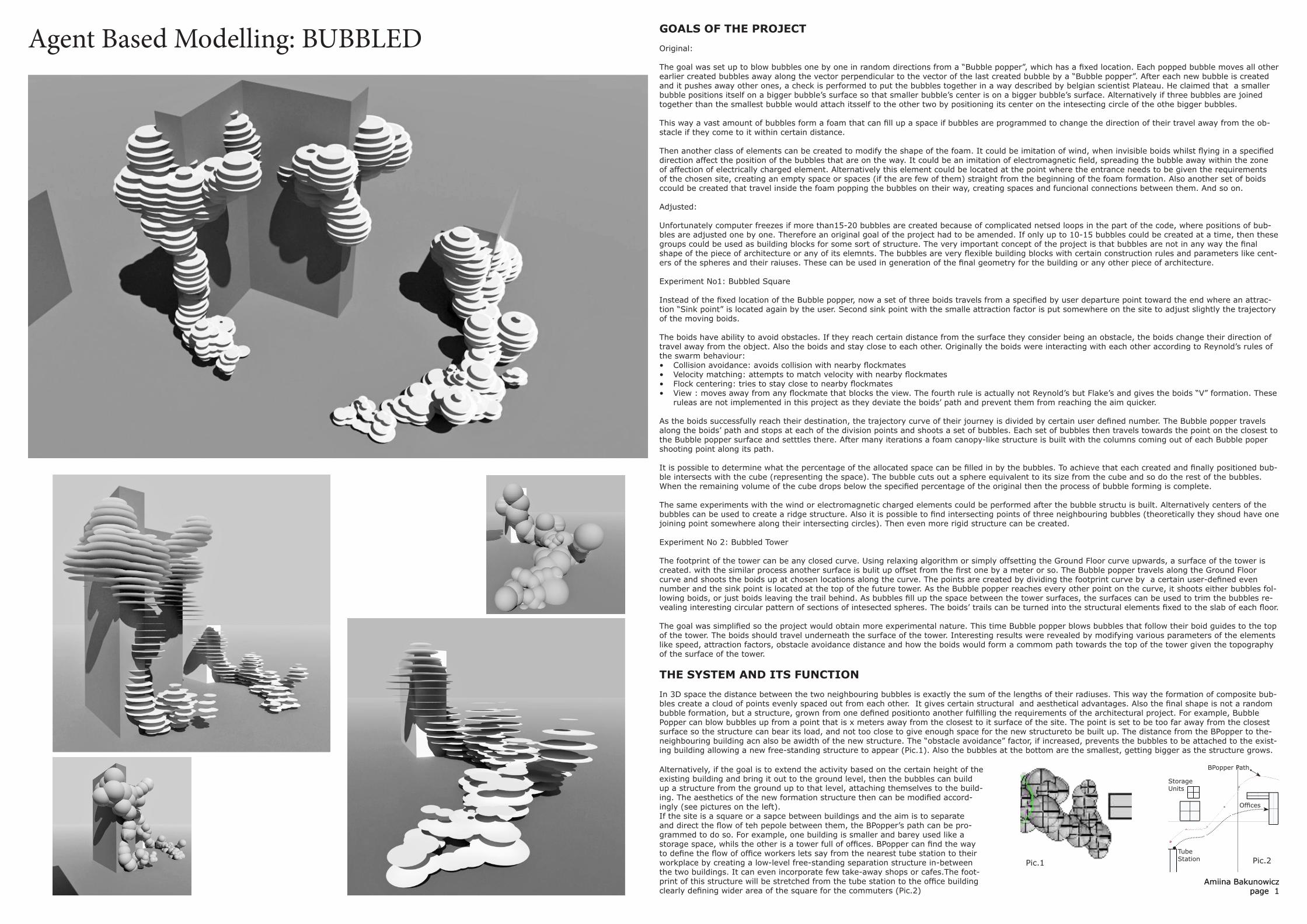
The goal was set up to blow bubbles one by one in random directions from a “Bubble popper”, which has a fixed location. Each popped bubble moves all other earlier created bubbles away along the vector perpendicular to the vector of the last created bubble by a “Bubble popper”. After each new bubble is created and it pushes away other ones, a check is performed to put the bubbles together in a way described by belgian scientist Plateau. He claimed that a smaller bubble positions itself on a bigger bubble’s surface so that smaller bubble’s center is on a bigger bubble’s surface. Alternatively if three bubbles are joined together than the smallest bubble would attach itsself to the other two by positioning its center on the intesecting circle of the othe bigger bubbles.
This way a vast amount of bubbles form a foam that can fill up a space if bubbles are programmed to change the direction of their travel away from the ob-stacle if they come to it within certain distance.
Then another class of elements can be created to modify the shape of the foam. It could be imitation of wind, when invisible boids whilst flying in a specified direction affect the position of the bubbles that are on the way. It could be an imitation of electromagnetic field, spreading the bubble away within the zone of affection of electrically charged element. Alternatively this element could be located at the point where the entrance needs to be given the requirements of the chosen site, creating an empty space or spaces (if the are few of them) straight from the beginning of the foam formation. Also another set of boids ccould be created that travel inside the foam popping the bubbles on their way, creating spaces and funcional connections between them. And so on.
Adjusted:
Unfortunately computer freezes if more than15-20 bubbles are created because of complicated netsed loops in the part of the code, where positions of bub-bles are adjusted one by one. Therefore an original goal of the project had to be amended. If only up to 10-15 bubbles could be created at a time, then these groups could be used as building blocks for some sort of structure. The very important concept of the project is that bubbles are not in any way the final shape of the piece of architecture or any of its elemnts. The bubbles are very flexible building blocks with certain construction rules and parameters like cent-ers of the spheres and their raiuses. These can be used in generation of the final geometry for the building or any other piece of architecture.
Experiment No1: Bubbled Square
Instead of the fixed location of the Bubble popper, now a set of three boids travels from a specified by user departure point toward the end where an attrac-tion “Sink point” is located again by the user. Second sink point with the smalle attraction factor is put somewhere on the site to adjust slightly the trajectory of the moving boids.
The boids have ability to avoid obstacles. If they reach certain distance from the surface they consider being an obstacle, the boids change their direction of travel away from the object. Also the boids and stay close to each other. Originally the boids were interacting with each other according to Reynold’s rules of the swarm behaviour:• Collision avoidance: avoids collision with nearby flockmates• Velocity matching: attempts to match velocity with nearby flockmates• Flock centering: tries to stay close to nearby flockmates• View : moves away from any flockmate that blocks the view. The fourth rule is actually not Reynold’s but Flake’s and gives the boids “V” formation. These
ruleas are not implemented in this project as they deviate the boids’ path and prevent them from reaching the aim quicker. As the boids successfully reach their destination, the trajectory curve of their journey is divided by certain user defined number. The Bubble popper travels along the boids’ path and stops at each of the division points and shoots a set of bubbles. Each set of bubbles then travels towards the point on the closest to the Bubble popper surface and setttles there. After many iterations a foam canopy-like structure is built with the columns coming out of each Bubble poper shooting point along its path.
It is possible to determine what the percentage of the allocated space can be filled in by the bubbles. To achieve that each created and finally positioned bub-ble intersects with the cube (representing the space). The bubble cuts out a sphere equivalent to its size from the cube and so do the rest of the bubbles. When the remaining volume of the cube drops below the specified percentage of the original then the process of bubble forming is complete.
The same experiments with the wind or electromagnetic charged elements could be performed after the bubble structu is built. Alternatively centers of the bubbles can be used to create a ridge structure. Also it is possible to find intersecting points of three neighbouring bubbles (theoretically they shoud have one joining point somewhere along their intersecting circles). Then even more rigid structure can be created.
Experiment No 2: Bubbled Tower
The footprint of the tower can be any closed curve. Using relaxing algorithm or simply offsetting the Ground Floor curve upwards, a surface of the tower is created. with the similar process another surface is bulit up offset from the first one by a meter or so. The Bubble popper travels along the Ground Floor curve and shoots the boids up at chosen locations along the curve. The points are created by dividing the footprint curve by a certain user-defined even number and the sink point is located at the top of the future tower. As the Bubble popper reaches every other point on the curve, it shoots either bubbles fol-lowing boids, or just boids leaving the trail behind. As bubbles fill up the space between the tower surfaces, the surfaces can be used to trim the bubbles re-vealing interesting circular pattern of sections of intesected spheres. The boids’ trails can be turned into the structural elements fixed to the slab of each floor.
The goal was simplified so the project would obtain more experimental nature. This time Bubble popper blows bubbles that follow their boid guides to the top of the tower. The boids should travel underneath the surface of the tower. Interesting results were revealed by modifying various parameters of the elements like speed, attraction factors, obstacle avoidance distance and how the boids would form a commom path towards the top of the tower given the topography of the surface of the tower.
THE SYSTEM AND ITS FUNCTION In 3D space the distance between the two neighbouring bubbles is exactly the sum of the lengths of their radiuses. This way the formation of composite bub-bles create a cloud of points evenly spaced out from each other. It gives certain structural and aesthetical advantages. Also the final shape is not a random bubble formation, but a structure, grown from one defined positionto another fulfilling the requirements of the architectural project. For example, Bubble Popper can blow bubbles up from a point that is x meters away from the closest to it surface of the site. The point is set to be too far away from the closest surface so the structure can bear its load, and not too close to give enough space for the new structureto be built up. The distance from the BPopper to the-neighbouring building acn also be awidth of the new structure. The “obstacle avoidance” factor, if increased, prevents the bubbles to be attached to the exist-ing building allowing a new free-standing structure to appear (Pic.1). Also the bubbles at the bottom are the smallest, getting bigger as the structure grows.
Pic.1 Pic.2Tube Station
Offices
Storage Units
BPopper Path
2
Agent Based Modelling: BUBBLED
Amiina Bakunowiczpage 2
MAIN STAGES OF THE CODE:
1. Choice of the building site2. Bubble Popper’s path and points3. Bubble foam creation4. Boids - Guides and Sink Points 5. Changed state of the attached bubbles6. Data and geometry rationalisation7. Example structures
2. Bubble Popper’s path and points
A set of three or more boids travels from a specified by user departure point toward the end where an attraction “Sink point” is located again by the user. Second sink point with the smalle attraction factor is put somewhere on the site to adjust slightly the trajectory of the moving boids.
The boids have ability to avoid obstacles. If they reach certain distance from the surface they consider being an obstacle, the boids change their direction of travel away from the object. Also the boids tend to stay close to each other.
Option 1. As the boids travel towards their destination, with each ctep they calculate the distance to the closest point of their closest obstacle. If it is bigger than certain user-defined number then they drop a point and it becomes a first location of the BPopper. As they continue moving towards the sink point, they keep checking the distance as previously to the closest surface and the distance to the previous dropped BPopper point. If both distances are bigger than defined in the code than another point is set for BPopper. This way the bubbles are connected to the surfaces and turned into columns at the BPop-per locations only in the spacious areas. There is no point putting a column if it is too close to another load-bearing structure.
Option 2. BPopper path is defined by the site conditions , butthe points areproduced by dividing the curve of the path by the certain amount
Option 3. The curve of BPopper path and howmany points it is divided into are both user-defined
3. Bubble foam creation
1. Plateau’s composite bubbles theory (from his book “Statique des Liquides”)
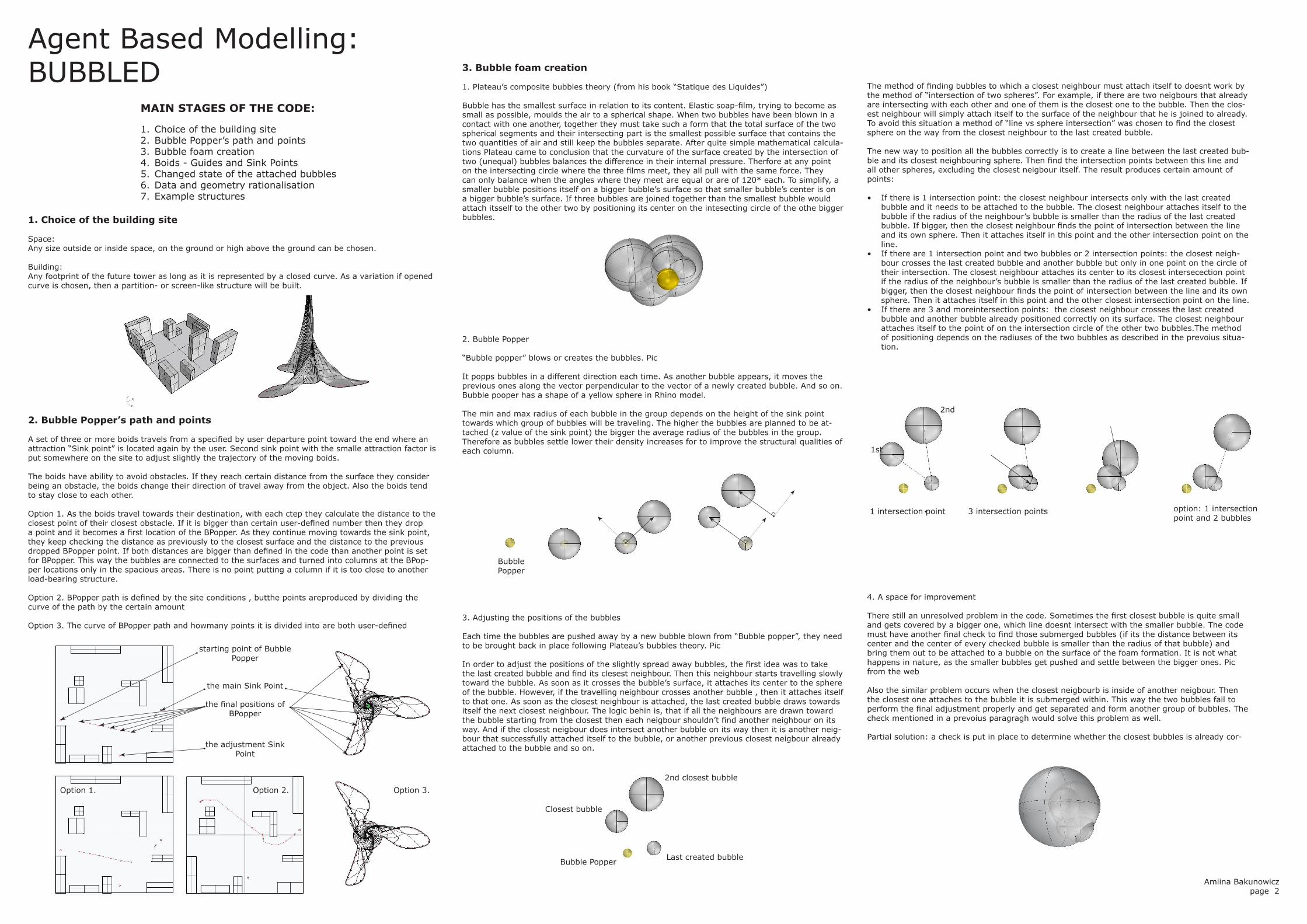
Bubble has the smallest surface in relation to its content. Elastic soap-film, trying to become as small as possible, moulds the air to a spherical shape. When two bubbles have been blown in a contact with one another, together they must take such a form that the total surface of the two spherical segments and their intersecting part is the smallest possible surface that contains the two quantities of air and still keep the bubbles separate. After quite simple mathematical calcula-tions Plateau came to conclusion that the curvature of the surface created by the intersection of two (unequal) bubbles balances the difference in their internal pressure. Therfore at any point on the intersecting circle where the three films meet, they all pull with the same force. They can only balance when the angles where they meet are equal or are of 120* each. To simplify, a smaller bubble positions itself on a bigger bubble’s surface so that smaller bubble’s center is on a bigger bubble’s surface. If three bubbles are joined together than the smallest bubble would attach itsself to the other two by positioning its center on the intesecting circle of the othe bigger bubbles.
The method of finding bubbles to which a closest neighbour must attach itself to doesnt work by the method of “intersection of two spheres”. For example, if there are two neigbours that already are intersecting with each other and one of them is the closest one to the bubble. Then the clos-est neighbour will simply attach itself to the surface of the neighbour that he is joined to already. To avoid this situation a method of “line vs sphere intersection” was chosen to find the closest sphere on the way from the closest neighbour to the last created bubble.
The new way to position all the bubbles correctly is to create a line between the last created bub-ble and its closest neighbouring sphere. Then find the intersection points between this line and all other spheres, excluding the closest neigbour itself. The result produces certain amount of points:
• If there is 1 intersection point: the closest neighbour intersects only with the last created bubble and it needs to be attached to the bubble. The closest neighbour attaches itself to the bubble if the radius of the neighbour’s bubble is smaller than the radius of the last created bubble. If bigger, then the closest neighbour finds the point of intersection between the line and its own sphere. Then it attaches itself in this point and the other intersection point on the line.
• If there are 1 intersection point and two bubbles or 2 intersection points: the closest neigh-bour crosses the last created bubble and another bubble but only in one point on the circle of their intersection. The closest neighbour attaches its center to its closest intersecection point if the radius of the neighbour’s bubble is smaller than the radius of the last created bubble. If bigger, then the closest neighbour finds the point of intersection between the line and its own sphere. Then it attaches itself in this point and the other closest intersection point on the line.
• If there are 3 and moreintersection points: the closest neighbour crosses the last created bubble and another bubble already positioned correctly on its surface. The closest neighbour attaches itself to the point of on the intersection circle of the other two bubbles.The method of positioning depends on the radiuses of the two bubbles as described in the prevoius situa-tion.
4. A space for improvement
There still an unresolved problem in the code. Sometimes the first closest bubble is quite small and gets covered by a bigger one, which line doesnt intersect with the smaller bubble. The code must have another final check to find those submerged bubbles (if its the distance between its center and the center of every checked bubble is smaller than the radius of that bubble) and bring them out to be attached to a bubble on the surface of the foam formation. It is not what happens in nature, as the smaller bubbles get pushed and settle between the bigger ones. Pic from the web
Also the similar problem occurs when the closest neigbourb is inside of another neigbour. Then the closest one attaches to the bubble it is submerged within. This way the two bubbles fail to perform the final adjustment properly and get separated and form another group of bubbles. The check mentioned in a prevoius paragragh would solve this problem as well.
Partial solution: a check is put in place to determine whether the closest bubbles is already cor-
3. Adjusting the positions of the bubbles
Each time the bubbles are pushed away by a new bubble blown from “Bubble popper”, they need to be brought back in place following Plateau’s bubbles theory. Pic
In order to adjust the positions of the slightly spread away bubbles, the first idea was to take the last created bubble and find its clesest neighbour. Then this neighbour starts travelling slowly toward the bubble. As soon as it crosses the bubble’s surface, it attaches its center to the sphere of the bubble. However, if the travelling neighbour crosses another bubble , then it attaches itself to that one. As soon as the closest neighbour is attached, the last created bubble draws towards itself the next closest neighbour. The logic behin is, that if all the neighbours are drawn toward the bubble starting from the closest then each neigbour shouldn’t find another neighbour on its way. And if the closest neigbour does intersect another bubble on its way then it is another neig-bour that successfully attached itself to the bubble, or another previous closest neigbour already attached to the bubble and so on.
2. Bubble Popper
“Bubble popper” blows or creates the bubbles. Pic
It popps bubbles in a different direction each time. As another bubble appears, it moves the previous ones along the vector perpendicular to the vector of a newly created bubble. And so on. Bubble pooper has a shape of a yellow sphere in Rhino model.
The min and max radius of each bubble in the group depends on the height of the sink point towards which group of bubbles will be traveling. The higher the bubbles are planned to be at-tached (z value of the sink point) the bigger the average radius of the bubbles in the group. Therefore as bubbles settle lower their density increases for to improve the structural qualities of each column. 1st
2nd
Bubble Popper
Last created bubble
Closest bubble
2nd closest bubble
Bubble Popper
1 intersection point 3 intersection points option: 1 intersection point and 2 bubbles
starting point of Bubble Popper
the main Sink Point
the adjustment Sink Point
the final positions of BPopper
Option 1. Option 2. Option 3.
1. Choice of the building site
Space:Any size outside or inside space, on the ground or high above the ground can be chosen.
Building:Any footprint of the future tower as long as it is represented by a closed curve. As a variation if opened curve is chosen, then a partition- or screen-like structure will be built.
3
Agent Based Modelling: BUBBLED4. Boids - Guides and Sink Points
If bubbles go around finding their way, attach to each other and then readjust their positons, it takes too much of a computational power and simply freezes the computer. Instead group of three bodyless boids is created that travel in the desired direction and bubbles follow them.
They travel towards their destination (a “Sink point”) from the position of a “Bubble popper”. Additional “Sink point” is created as well with the smalle attraction factor in order to be able to redirect the trajec-tory of the boids slightly if needed.
The boids have ability to avoid obstacles and also they tend to stay close to each other.
For example, If one of the boids gets lost or deviates from the destination path then the other two will be ablle to pull it towards them as they are programmed to stay together and travel in the same direc-tion. That’s why three or more boids have to be used to successfully direct a set of bubbles towards the final sink point. Just moving one bubble within a group would have a higher risk of bubbles either tak-ing a wrong turn by being pushed away from the surface of an obstacle or being attracted to a wrong sink point.
Having boids as their invisible guides, group of three or more bubbles travel in the the average direc-tion of the boids, kepping slightly behnd them.In the case of Bubbled Square the speed of the boids decreases as they approach the sink points to make sure that they are not pushed away from the surface and do not get carried away in the wrong direction. However in the example of the tower the initial speed needs to maintained quite low so the boids do not go through the building’s surface. So the speed was maintained the same throughout the whole journey of the boids.
In the example of the tower, with the each round of the Bubble popper covering the length of the tower footprint the amount of boids steps up could decrease gradually. This could stop the boids to travel too far away from the surface of the building if they manage to escape.
5. Changed state of the attached bubbles
Space:
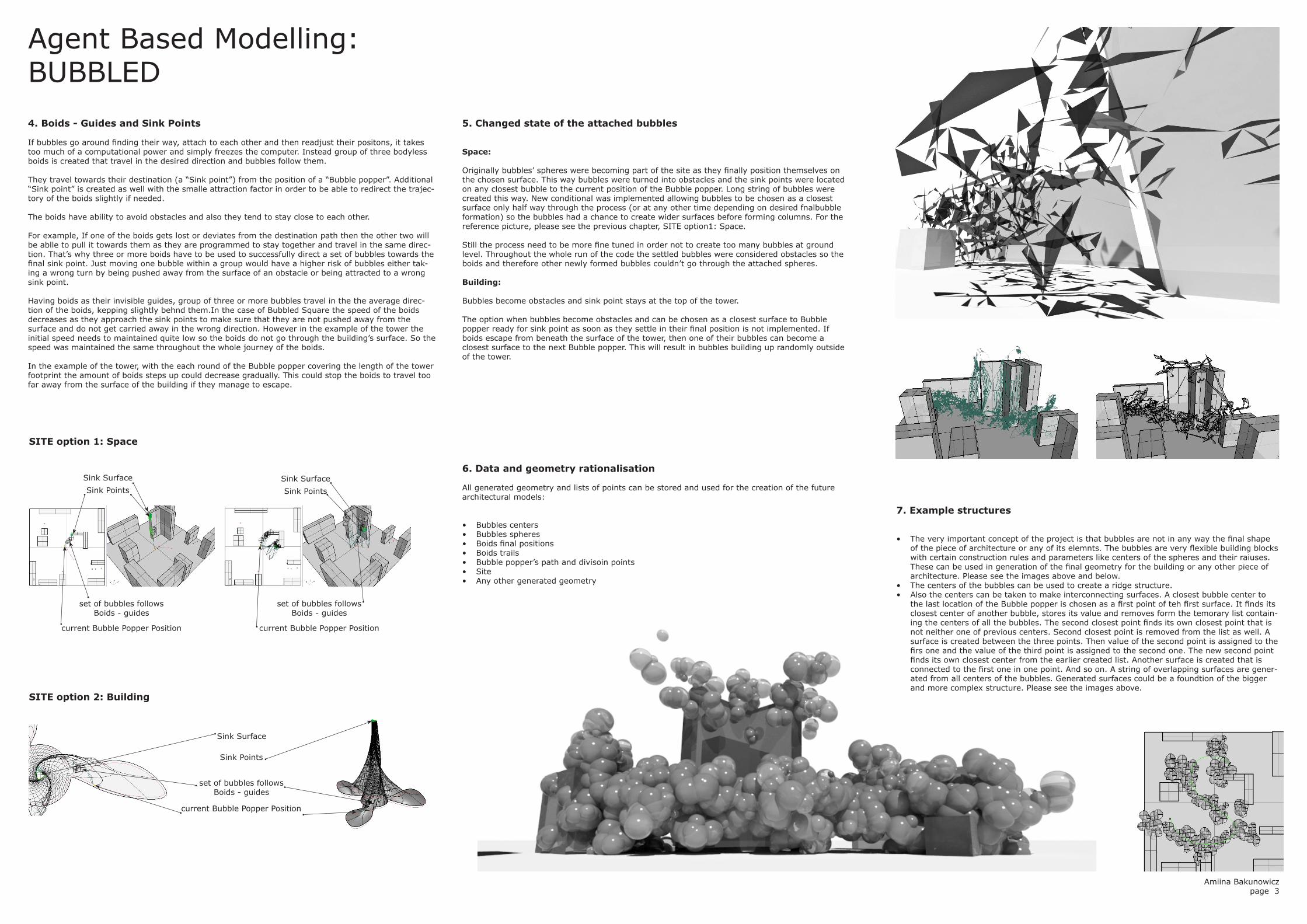
Originally bubbles’ spheres were becoming part of the site as they finally position themselves on the chosen surface. This way bubbles were turned into obstacles and the sink points were located on any closest bubble to the current position of the Bubble popper. Long string of bubbles were created this way. New conditional was implemented allowing bubbles to be chosen as a closest surface only half way through the process (or at any other time depending on desired fnalbubble formation) so the bubbles had a chance to create wider surfaces before forming columns. For the reference picture, please see the previous chapter, SITE option1: Space.
Still the process need to be more fine tuned in order not to create too many bubbles at ground level. Throughout the whole run of the code the settled bubbles were considered obstacles so the boids and therefore other newly formed bubbles couldn’t go through the attached spheres.
Building:
Bubbles become obstacles and sink point stays at the top of the tower.
The option when bubbles become obstacles and can be chosen as a closest surface to Bubble popper ready for sink point as soon as they settle in their final position is not implemented. If boids escape from beneath the surface of the tower, then one of their bubbles can become a closest surface to the next Bubble popper. This will result in bubbles building up randomly outside of the tower.
6. Data and geometry rationalisation
All generated geometry and lists of points can be stored and used for the creation of the future architectural models:
• Bubbles centers• Bubbles spheres• Boids final positions• Boids trails• Bubble popper’s path and divisoin points• Site• Any other generated geometry
current Bubble Popper Position
current Bubble Popper Position
current Bubble Popper Position
set of bubbles follows Boids - guides
set of bubbles follows Boids - guides
set of bubbles follows Boids - guides
Sink Points
Sink Points
Sink Points
Sink Surface
Sink Surface
Sink Surface
SITE option 1: Space
SITE option 2: Building
7. Example structures
• The very important concept of the project is that bubbles are not in any way the final shape of the piece of architecture or any of its elemnts. The bubbles are very flexible building blocks with certain construction rules and parameters like centers of the spheres and their raiuses. These can be used in generation of the final geometry for the building or any other piece of architecture. Please see the images above and below.
• The centers of the bubbles can be used to create a ridge structure. • Also the centers can be taken to make interconnecting surfaces. A closest bubble center to
the last location of the Bubble popper is chosen as a first point of teh first surface. It finds its closest center of another bubble, stores its value and removes form the temorary list contain-ing the centers of all the bubbles. The second closest point finds its own closest point that is not neither one of previous centers. Second closest point is removed from the list as well. A surface is created between the three points. Then value of the second point is assigned to the firs one and the value of the third point is assigned to the second one. The new second point finds its own closest center from the earlier created list. Another surface is created that is connected to the first one in one point. And so on. A string of overlapping surfaces are gener-ated from all centers of the bubbles. Generated surfaces could be a foundtion of the bigger and more complex structure. Please see the images above.
Amiina Bakunowiczpage 3
4
Msc Architecture: Computing and Design 2012/2013no :: u1235266tutors :: Emmanouil Zaroukas, John Harding
Agent Based Modelling: BUBBLED
Amiina Bakunowiczpage 4
OUTCOME OF THE PROJECT AND CONCLUSIONS• The very important concept of the project is that bubbles are not in any way the final shape of the piece of architecture or any
of its elemnts. The bubbles are very flexible building blocks with certain construction rules and parameters like centers of the spheres and their raiuses. These can be used in generation of the final geometry for the building or any other piece of architec-ture.
• The bubbles can be used in a way as bricks are used for building up surfaces and spaces. However the spheres joined together the way that their centers are always away from each other by the sum of their radiuses. The structures built from the compos-ite bubbles form volumes in a much more flexible as they can move around each others centers by 360 Degrees. They can be moved not only by physically relocating their centers but also by changing their radiuses.
• The location of the structure can be determined by specifying the rules for the Bubble Popper path. It can be programmed to find the biggest space between the surfaces of the existing site, or to stay within a certain distance from another building or ob-ject, or to find a certain surface, and so on. So Bubble Popper determines future structure’s x and y dimensions.
• Whilst Sink points create z dimension for the future structure. There can be one or more of them located at certain height and have a required location in relation to each Bubble Popper location.
• In between the ground and top levels the shape of the surface can be controlled by the temporary surfaces unde or above which the bubbles suppose to travel slowly building up volume as they settle closer and closer the the ground.
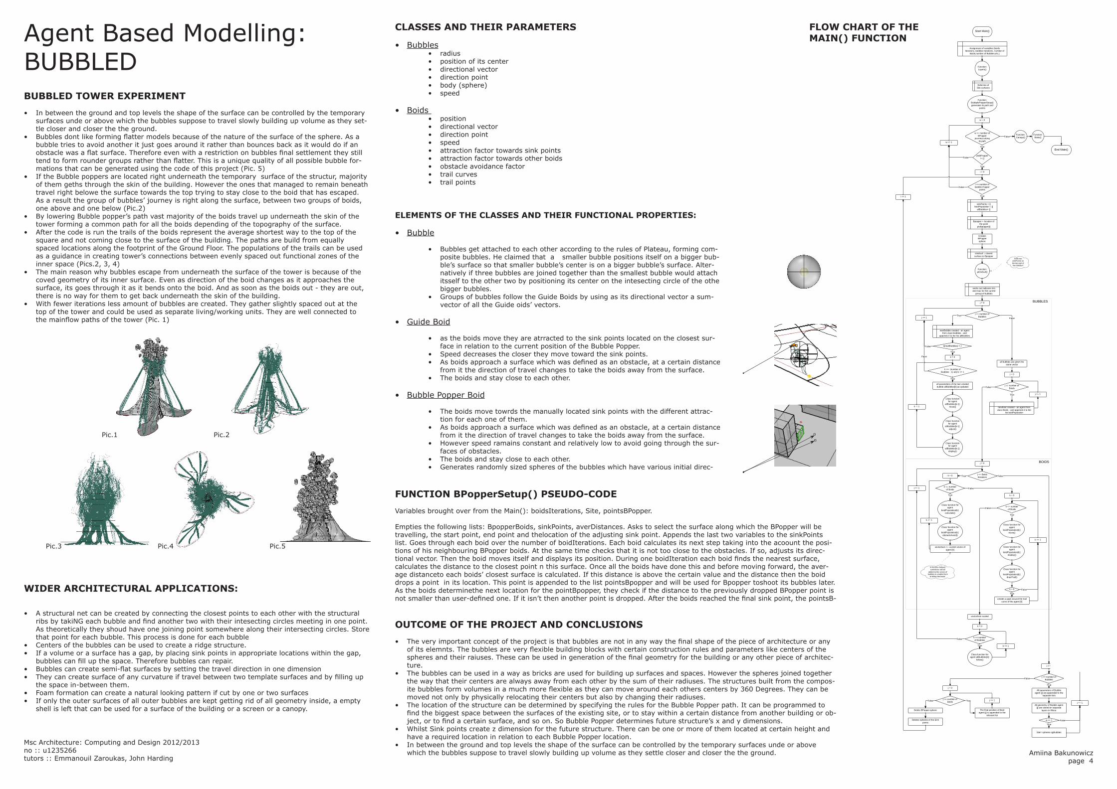
BUBBLED TOWER EXPERIMENT• In between the ground and top levels the shape of the surface can be controlled by the temporary
surfaces unde or above which the bubbles suppose to travel slowly building up volume as they set-tle closer and closer the the ground.
• Bubbles dont like forming flatter models because of the nature of the surface of the sphere. As a bubble tries to avoid another it just goes around it rather than bounces back as it would do if an obstacle was a flat surface. Therefore even with a restriction on bubbles final settlement they still tend to form rounder groups rather than flatter. This is a unique quality of all possible bubble for-mations that can be generated using the code of this project (Pic. 5)
• If the Bubble poppers are located right underneath the temporary surface of the structur, majority of them geths through the skin of the building. However the ones that managed to remain beneath travel right belowe the surface towards the top trying to stay close to the boid that has escaped. As a result the group of bubbles’ journey is right along the surface, between two groups of boids, one above and one below (Pic.2)
• By lowering Bubble popper’s path vast majority of the boids travel up underneath the skin of the tower forming a common path for all the boids depending of the topography of the surface.
• After the code is run the trails of the boids represent the average shortest way to the top of the square and not coming close to the surface of the building. The paths are build from equally spaced locations along the footprint of the Ground Floor. The populations of the trails can be used as a guidance in creating tower’s connections between evenly spaced out functional zones of the inner space (Pics.2, 3, 4)
• The main reason why bubbles escape from underneath the surface of the tower is because of the coved geometry of its inner surface. Even as direction of the boid changes as it approaches the surface, its goes through it as it bends onto the boid. And as soon as the boids out - they are out, there is no way for them to get back underneath the skin of the building.
• With fewer iterations less amount of bubbles are created. They gather slightly spaced out at the top of the tower and could be used as separate living/working units. They are well connected to the mainflow paths of the tower (Pic. 1)
FUNCTION BPopperSetup() PSEUDO-CODE Variables brought over from the Main(): boidsIterations, Site, pointsBPopper.
Empties the following lists: BpopperBoids, sinkPoints, averDistances. Asks to select the surface along which the BPopper will be travelling, the start point, end point and thelocation of the adjusting sink point. Appends the last two variables to the sinkPoints list. Goes through each boid over the number of boidIterations. Each boid calculates its next step taking into the acoount the posi-tions of his neighbouring BPopper boids. At the same time checks that it is not too close to the obstacles. If so, adjusts its direc-tional vector. Then the boid moves itself and displays its position. During one boidIteration each boid finds the nearest surface, calculates the distance to the closest point n this surface. Once all the boids have done this and before moving forward, the aver-age distanceto each boids’ closest surface is calculated. If this distance is above the certain value and the distance then the boid drops a point in its location. This point is appended to the list pointsBpopper and will be used for Bpopper toshoot its bubbles later. As the boids determinethe next location for the pointBpopper, they check if the distance to the previously dropped BPopper point is not smaller than user-defined one. If it isn’t then another point is dropped. After the boids reached the final sink point, the pointsB-
CLASSES AND THEIR PARAMETERS
• Bubbles• radius• position of its center• directional vector • direction point• body (sphere)• speed
• Boids • position • directional vector • direction point• speed• attraction factor towards sink points• attraction factor towards other boids• obstacle avoidance factor• trail curves• trail points
ELEMENTS OF THE CLASSES AND THEIR FUNCTIONAL PROPERTIES:
• Bubble
• Bubbles get attached to each other according to the rules of Plateau, forming com-posite bubbles. He claimed that a smaller bubble positions itself on a bigger bub-ble’s surface so that smaller bubble’s center is on a bigger bubble’s surface. Alter-natively if three bubbles are joined together than the smallest bubble would attach itsself to the other two by positioning its center on the intesecting circle of the othe bigger bubbles.
• Groups of bubbles follow the Guide Boids by using as its directional vector a sum-vector of all the Guide oids’ vectors.
• Guide Boid
• as the boids move they are atrracted to the sink points located on the closest sur-face in relation to the current position of the Bubble Popper.
• Speed decreases the closer they move toward the sink points. • As boids approach a surface which was defined as an obstacle, at a certain distance
from it the direction of travel changes to take the boids away from the surface. • The boids and stay close to each other.
• Bubble Popper Boid
• The boids move towrds the manually located sink points with the different attrac-tion for each one of them.
• As boids approach a surface which was defined as an obstacle, at a certain distance from it the direction of travel changes to take the boids away from the surface.
• However speed ramains constant and relatively low to avoid going through the sur-faces of obstacles.
• The boids and stay close to each other.• Generates randomly sized spheres of the bubbles which have various initial direc-
FLOW CHART OF THE MAIN() FUNCTION
Pic.1
Pic.3
Pic.2
Pic.4 Pic.5
WIDER ARCHITECTURAL APPLICATIONS:
• A structural net can be created by connecting the closest points to each other with the structural ribs by takiNG each bubble and find another two with their intesecting circles meeting in one point. As theoretically they shoud have one joining point somewhere along their intersecting circles. Store that point for each bubble. This process is done for each bubble
• Centers of the bubbles can be used to create a ridge structure.• If a volume or a surface has a gap, by placing sink points in appropriate locations within the gap,
bubbles can fill up the space. Therefore bubbles can repair.• Bubbles can create semi-flat surfaces by setting the travel direction in one dimension• They can create surface of any curvature if travel between two template surfaces and by filling up
the space in-between them.• Foam formation can create a natural looking pattern if cut by one or two surfaces• If only the outer surfaces of all outer bubbles are kept getting rid of all geometry inside, a empty
shell is left that can be used for a surface of the building or a screen or a canopy.