american art museum | northeast united … art museum | northeast united states thesis ... sustersic...
TRANSCRIPT

SEAN FELTON | STRUCTURAL
AMERICAN ART MUSEUM | NORTHEAST UNITED STATES
THESIS PROPOSAL
ADVISOR: SUSTERSIC
DECEMBER 14, 2012
Thesis Proposal | American Art Museum |1
Sean Felton | Structural Option | Advisor: Sustersic | December 14, 2012
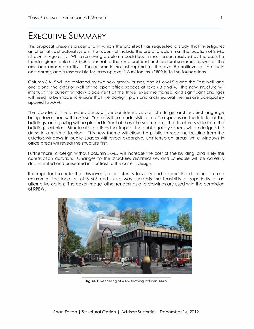
EXECUTIVE SUMMARY This proposal presents a scenario in which the architect has requested a study that investigates
an alternative structural system that does not include the use of a column at the location of 3-M.5
(shown in Figure 1). While removing a column could be, in most cases, resolved by the use of a
transfer girder, column 3-M.5 is central to the structural and architectural schemes as well as the
cost and constructability. The column is the last support for the level 5 cantilever at the south
east corner, and is responsible for carrying over 1.8 million lbs. (1800 k) to the foundations.
Column 3-M.5 will be replaced by two new gravity trusses, one at level 5 along the East wall, and
one along the exterior wall of the open office spaces at levels 3 and 4. The new structure will
interrupt the current window placement at the three levels mentioned, and significant changes
will need to be made to ensure that the daylight plan and architectural themes are adequately
applied to AAM.
The façades at the affected areas will be considered as part of a larger architectural language
being developed within AAM. Trusses will be made visible in office spaces on the interior of the
buildings, and glazing will be placed in front of these trusses to make the structure visible from the
building’s exterior. Structural alterations that impact the public gallery spaces will be designed to
do so in a minimal fashion. This new theme will allow the public to read the building from the
exterior; windows in public spaces will reveal expansive, uninterrupted areas, while windows in
office areas will reveal the structure first.
Furthermore, a design without column 3-M.5 will increase the cost of the building, and likely the
construction duration. Changes to the structure, architecture, and schedule will be carefully
documented and presented in contrast to the current design.
It is important to note that this investigation intends to verify and support the decision to use a
column at the location of 3-M.5 and in no way suggests the feasibility or superiority of an
alternative option. The cover image, other renderings and drawings are used with the permission
of RPBW.
Figure 1: Rendering of AAM showing column 3-M.5

Thesis Proposal | American Art Museum |2
Sean Felton | Structural Option | Advisor: Sustersic | December 14, 2012
TABLE OF CONTENTS
Executive Summary ............................................................................................................................................ 1
Table of Contents ............................................................................................................................................... 2
Introduction .......................................................................................................................................................... 3
Technical Background and Overview ............................................................................................................ 4
Problem Statement ............................................................................................................................................. 9
Proposed Solution ............................................................................................................................................... 9
Breadth Topics ................................................................................................................................................... 10
Tasks & Tools ....................................................................................................................................................... 11
Thesis Schedule .................................................................................................................................................. 12
Conclusion.......................................................................................................................................................... 13
Thesis Proposal | American Art Museum |3
Sean Felton | Structural Option | Advisor: Sustersic | December 14, 2012
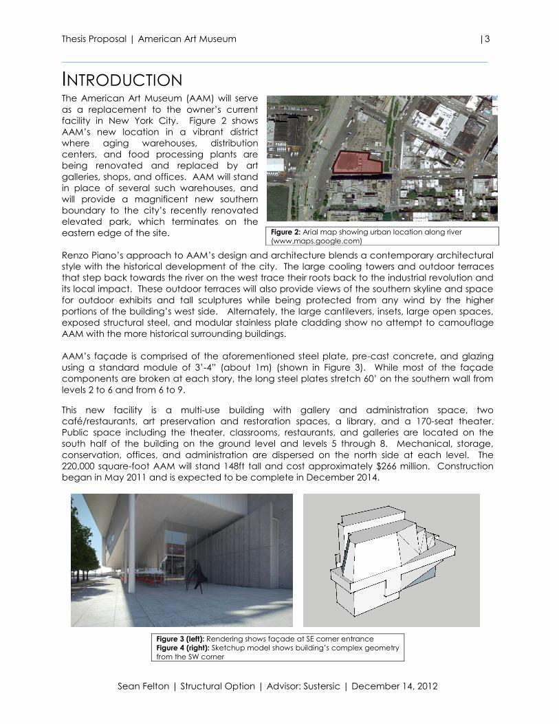
INTRODUCTION The American Art Museum (AAM) will serve
as a replacement to the owner’s current
facility in New York City. Figure 2 shows
AAM’s new location in a vibrant district
where aging warehouses, distribution
centers, and food processing plants are
being renovated and replaced by art
galleries, shops, and offices. AAM will stand
in place of several such warehouses, and
will provide a magnificent new southern
boundary to the city’s recently renovated
elevated park, which terminates on the
eastern edge of the site.
Renzo Piano’s approach to AAM’s design and architecture blends a contemporary architectural
style with the historical development of the city. The large cooling towers and outdoor terraces
that step back towards the river on the west trace their roots back to the industrial revolution and
its local impact. These outdoor terraces will also provide views of the southern skyline and space
for outdoor exhibits and tall sculptures while being protected from any wind by the higher
portions of the building’s west side. Alternately, the large cantilevers, insets, large open spaces,
exposed structural steel, and modular stainless plate cladding show no attempt to camouflage
AAM with the more historical surrounding buildings.
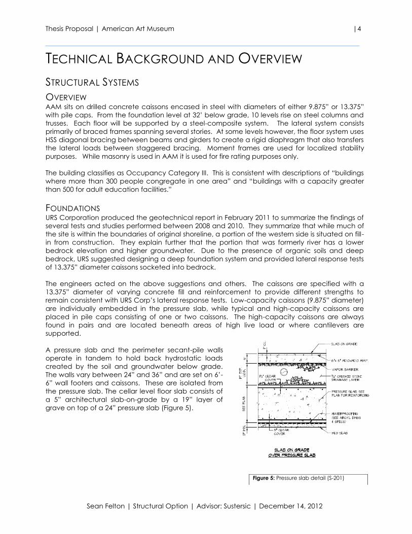
AAM’s façade is comprised of the aforementioned steel plate, pre-cast concrete, and glazing
using a standard module of 3’-4” (about 1m) (shown in Figure 3). While most of the façade
components are broken at each story, the long steel plates stretch 60’ on the southern wall from
levels 2 to 6 and from 6 to 9.
This new facility is a multi-use building with gallery and administration space, two
café/restaurants, art preservation and restoration spaces, a library, and a 170-seat theater.
Public space including the theater, classrooms, restaurants, and galleries are located on the
south half of the building on the ground level and levels 5 through 8. Mechanical, storage,
conservation, offices, and administration are dispersed on the north side at each level. The
220,000 square-foot AAM will stand 148ft tall and cost approximately $266 million. Construction
began in May 2011 and is expected to be complete in December 2014.
Figure 2: Arial map showing urban location along river
(www.maps.google.com)
Figure 3 (left): Rendering shows façade at SE corner entrance
Figure 4 (right): Sketchup model shows building’s complex geometry
from the SW corner
Thesis Proposal | American Art Museum |4
Sean Felton | Structural Option | Advisor: Sustersic | December 14, 2012
TECHNICAL BACKGROUND AND OVERVIEW
STRUCTURAL SYSTEMS
OVERVIEW AAM sits on drilled concrete caissons encased in steel with diameters of either 9.875” or 13.375”
with pile caps. From the foundation level at 32’ below grade, 10 levels rise on steel columns and
trusses. Each floor will be supported by a steel-composite system. The lateral system consists
primarily of braced frames spanning several stories. At some levels however, the floor system uses
HSS diagonal bracing between beams and girders to create a rigid diaphragm that also transfers
the lateral loads between staggered bracing. Moment frames are used for localized stability
purposes. While masonry is used in AAM it is used for fire rating purposes only.
The building classifies as Occupancy Category III. This is consistent with descriptions of “buildings
where more than 300 people congregate in one area” and “buildings with a capacity greater
than 500 for adult education facilities.”
FOUNDATIONS URS Corporation produced the geotechnical report in February 2011 to summarize the findings of
several tests and studies performed between 2008 and 2010. They summarize that while much of
the site is within the boundaries of original shoreline, a portion of the western side is situated on fill-
in from construction. They explain further that the portion that was formerly river has a lower
bedrock elevation and higher groundwater. Due to the presence of organic soils and deep
bedrock, URS suggested designing a deep foundation system and provided lateral response tests
of 13.375” diameter caissons socketed into bedrock.
The engineers acted on the above suggestions and others. The caissons are specified with a
13.375” diameter of varying concrete fill and reinforcement to provide different strengths to
remain consistent with URS Corp’s lateral response tests. Low-capacity caissons (9.875” diameter)
are individually embedded in the pressure slab, while typical and high-capacity caissons are
placed in pile caps consisting of one or two caissons. The high-capacity caissons are always
found in pairs and are located beneath areas of high live load or where cantilevers are
supported.
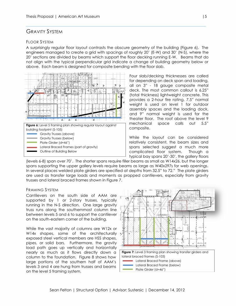
A pressure slab and the perimeter secant-pile walls
operate in tandem to hold back hydrostatic loads
created by the soil and groundwater below grade.
The walls vary between 24” and 36” and are set on 6’-
6” wall footers and caissons. These are isolated from
the pressure slab. The cellar level floor slab consists of
a 5” architectural slab-on-grade by a 19” layer of
grave on top of a 24” pressure slab (Figure 5).
Figure 5: Pressure slab detail (S-201)
Thesis Proposal | American Art Museum |5
Sean Felton | Structural Option | Advisor: Sustersic | December 14, 2012
GRAVITY SYSTEM
FLOOR SYSTEM
A surprisingly regular floor layout contrasts the obscure geometry of the building (Figure 6). The
engineers managed to create a grid with spacings of roughly 20’ (E-W) and 30’ (N-S), where the
20’ sections are divided by beams which support the floor decking running E-W. Beams that do
not align with the typical perpendicular grid indicate a change of building geometry below or
above. Each beam is designed for composite bending with the floor slab.
Four slab/decking thicknesses are called
for depending on deck span and loading,
all on 3” - 18 gauge composite metal
deck. The most common callout is 6.25”
(total thickness) lightweight concrete. This
provides a 2-hour fire rating. 7.5” normal
weight is used on level 1 for outdoor
assembly spaces and the loading dock,
and 9” normal weight is used for the
theater floor. The roof above the level 9
mechanical space calls out 5.5”
composite.
While the layout can be considered
relatively consistent, the beam sizes and
spans selected suggest a much more
complicated floor system. Though a
typical bay spans 20’-30’, the gallery floors
(levels 6-8) span over 70’. The shorter spans require filler beams as small as W14x26, but the longer
spans supporting the upper gallery levels require beams as large as W40x297s for web openings.
In several places welded plate girders are specified at depths from 32.5” to 72.” The plate girders
are used as transfer large loads and moments as propped cantilevers, especially from gravity
trusses and lateral braced frames shown in Figure 7.
FRAMING SYSTEM
Cantilevers on the south side of AAM are
supported by 1 or 2-story trusses, typically
running in the N-S direction. One large gravity
truss runs along the southernmost column line
between levels 5 and 6 to support the cantilever
on the south-eastern corner of the building.
While the vast majority of columns are W12x or
W14x shapes, some of the architecturally
exposed steel vertical members are HSS shapes,
pipes, or solid bars. Furthermore, the gravity
load path goes up vertically and horizontally
nearly as much as it flows directly down a
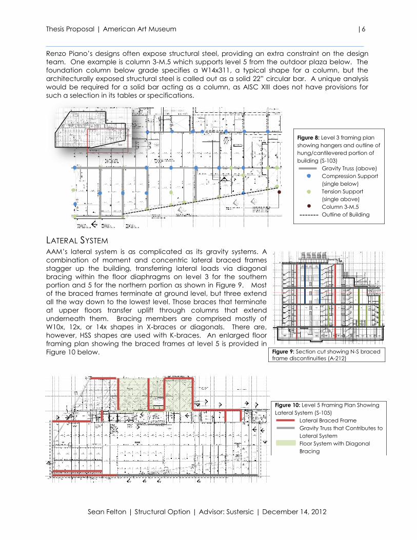
column to the foundation. Figure 8 shows how
large portions of the southern half of AAM’s
levels 3 and 4 are hung from trusses and beams
on the level 5 framing system.
Figure 6: Level 5 framing plan showing regular layout against
building footprint (S-105)
Gravity Trusses (above)
Gravity Trusses (below)
Plate Girder (d=46”)
Lateral Braced Frames (part of gravity)
Outline of Building Below
Figure 7: Level 3 framing plan showing transfer girders and
lateral braced frames (S-103)
Lateral Braced Frame (above)
Lateral Braced Frame (below)
Plate Girder (d=46”)
Thesis Proposal | American Art Museum |6
Sean Felton | Structural Option | Advisor: Sustersic | December 14, 2012
Renzo Piano’s designs often expose structural steel, providing an extra constraint on the design
team. One example is column 3-M.5 which supports level 5 from the outdoor plaza below. The
foundation column below grade specifies a W14x311, a typical shape for a column, but the
architecturally exposed structural steel is called out as a solid 22” circular bar. A unique analysis
would be required for a solid bar acting as a column, as AISC XIII does not have provisions for
such a selection in its tables or specifications.
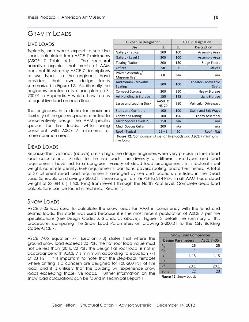
LATERAL SYSTEM AAM’s lateral system is as complicated as its gravity systems. A
combination of moment and concentric lateral braced frames
stagger up the building, transferring lateral loads via diagonal
bracing within the floor diaphragms on level 3 for the southern
portion and 5 for the northern portion as shown in Figure 9. Most
of the braced frames terminate at ground level, but three extend
all the way down to the lowest level. Those braces that terminate
at upper floors transfer uplift through columns that extend
underneath them. Bracing members are comprised mostly of
W10x, 12x, or 14x shapes in X-braces or diagonals. There are,
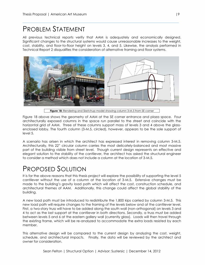
however, HSS shapes are used with K-braces. An enlarged floor
framing plan showing the braced frames at level 5 is provided in
Figure 10 below.
Figure 8: Level 3 framing plan
showing hangers and outline of
hung/cantilevered portion of
building (S-103)
Gravity Truss (above)
Compression Support
(single below)
Tension Support
(single above)
Column 3-M.5
Outline of Building
Figure 9: Section cut showing N-S braced
frame discontinuities (A-212)
Figure 10: Level 5 Framing Plan Showing
Lateral System (S-105)
Lateral Braced Frame
Gravity Truss that Contributes to
Lateral System
Floor System with Diagonal
Bracing

Thesis Proposal | American Art Museum |7
Sean Felton | Structural Option | Advisor: Sustersic | December 14, 2012
DESIGN CODES & STANDARDS
The design codes listed for compliance of structural design can be inferred from drawing S-200.01
and Specification Section 014100.2.B:
International Code Council, 2007 edition with local amendments including:
o Building Code
o Fire Code
ASCE 7-05: Minimum Design Loads for Buildings and other Structures
ACI 318 -08: Building Code Requirements for Structural Concrete (LRFD)
AISC XIII: Specifications for Structural Steel Buildings (LRFD)
AWS D1.1: American Welding Society Code for Welding in Building Construction
Other codes not applicable to the structural systems of the building can be found in the
specifications.
MATERIALS SPECIFICATIONS The different materials specifications are summarized in Figure 11 below. Additional information
can be found on drawing S-200.01 in Appendix A.
Materials Specifications
Concrete & Reinforcement Structural Steel
Wt Use f'c
(psi) Shape ASTM Gr. Fy
(ksi)
LW Floor Slabs (typ) 4000 Wide Flange A992 - 50
NW Foundations (walls, slab, pile caps, grade beams)
5000 Hollow Structural A500 B 46
Structural Pipe A501/A53 -/B 30
NW Composite Column Alternate 8000 Channels A36 - 36
NW Other 5000 Angles A36 - 36
Plates A36 - 36
Gr. Use ASTM Connection Bolts A325-SC - 80
70 Reinforcement A185 (3/4") Anchor Bolts F1554 36 36
70 Welded Wire Fabric A185
Figure 11: Summary of Structural Materials Specifications in AAM
Thesis Proposal | American Art Museum |8
Sean Felton | Structural Option | Advisor: Sustersic | December 14, 2012
GRAVITY LOADS
LIVE LOADS Typically, one would expect to see Live
Loads calculated from ASCE 7 minimums
(ASCE 7 Table 4-1). The structural
narrative explains that much of AAM
does not fit with any ASCE 7 descriptions
of use types, so the engineers have
provided their own design loads
summarized in Figure 12. Additionally the
engineers created a live load plan on S-
200.01 in Appendix A which shows areas
of equal live load on each floor.
The engineers, in a desire for maximum
flexibility of the gallery spaces, elected to
conservatively design the AAM-specific
spaces for live loads, while being
consistent with ASCE 7 minimums for
more common areas.
DEAD LOADS Because the live loads (above) are so high, the design engineers were very precise in their dead
load calculations. Similar to the live loads, the diversity of different use types and load
requirements have led to a congruent variety of dead load arrangements in structural steel
weight, concrete density, MEP requirements, partitions, pavers, roofing, and other finishes. A total
of 37 different dead load requirements, arranged by use and location, are listed in the Dead
Load Schedule on drawing S-200.01. These range from 76 PSF to 214 PSF. In all, AAM has a dead
weight of 23,084 k (11,500 tons) from level 1 through the North Roof level. Complete dead load
calculations can be found in Technical Report 1.
SNOW LOADS ASCE 7-05 was used to calculate the snow loads for AAM in consistency with the wind and
seismic loads. This code was used because it is the most recent publication of ASCE 7 per the
specifications (see Design Codes & Standards above). Figure 13 details the summary of this
procedure, comparing the Snow Load Parameters on drawing S-200.01 to the City Building
Code/ASCE 7.
ASCE 7-05 equation 7-1 (section 7.3) states that where the
ground snow load exceeds 20 PSF, the flat roof load value must
not be less than (20)Is. 22 PSF, the design flat roof load, is not in
accordance with ASCE 7’s minimum according to equation 7-1
of 23 PSF. It is important to note that the step-back terraces
where drifting is a concern are designed for 100-200 PSF of live
load, and it is unlikely that the building will experience snow
loads exceeding those live loads. Further information on the
snow load calculations can be found in Technical Report 1.
LL Schedule Designation ASCE 7 Designation
Use LL LL Description
Gallery - Typical 100 100 Assembly Area
Gallery - Level 5 200 100 Assembly Area
Testing Platform 200 150 Stage Floors
Offices 50 50 Offices
Private Assembly/ Museum Use
60 n/a n/a
Auditorium - Movable Seating
100 100 Theater - Moveable
Seats
Compact Storage 300 250 Heavy Storage
Art Handling & Storage 150 125 Light Storage
Largo and Loading Dock AASHTO
HS-20 250 Vehicular Driveways
Stairs and Corridors 100 100 Stairs and Exit Ways
Lobby and Dining 100 100 Lobby Assembly
Mech Spaces Levels 2, 9 150 n/a n/a
Mech Spaces Cellar 200 n/a n/a
Roof - Typical 22 + S 20 Roof - Flat
Figure 12: Comparison of design live loads and ASCE 7 minimum
live loads
Snow Load Comparison
Design Parameters ASCE 7 -05
Pg 25 25
Ct 1 1
Is 1.15 1.15
Ce 1 1
Pf 20.1 20.1
20 Is 22 23
Figure 13: Snow Loads
Thesis Proposal | American Art Museum |9
Sean Felton | Structural Option | Advisor: Sustersic | December 14, 2012
PROBLEM STATEMENT All previous technical reports verify that AAM is adequately and economically designed.
Significant changes to the structural systems would cause unreasonable increases to the weight,
cost, stability, and floor-to-floor height on levels 3, 4, and 5. Likewise, the analysis performed in
Technical Report 2 disqualifies the consideration of alternative framing and floor systems.
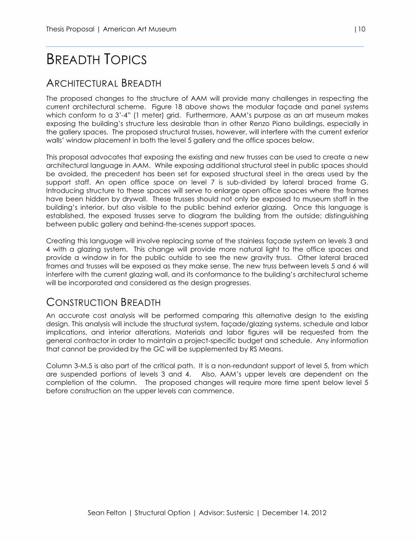
Figure 18 above shows the geometry of AAM at the SE corner entrance and plaza space. Four
architecturally exposed columns in the space run parallel to the street and coincide with the
horizontal grid of AAM. Three of these columns support mass of levels 3 and 4 above the glass-
enclosed lobby. The fourth column (3-M.5, circled), however, appears to be the sole support of
level 5.
A scenario has arisen in which the architect has expressed interest in removing column 3-M.5.
Architecturally, this 22” circular column carries the most delicately-balanced and most massive
part of the building visible from street level. Though current design represents an effective and
elegant solution to the stability of the cantilever, the architect has asked the structural engineer
to consider a method which does not include a column at the location of 3-M.5.
PROPOSED SOLUTION It is for the above reasons that this thesis project will explore the possibility of supporting the level 5
cantilever without the use of a column at the location of 3-M.5. Extensive changes must be
made to the building’s gravity load path which will affect the cost, construction schedule, and
architectural themes of AAM. Additionally, this change could affect the global stability of the
building.
A new load path must be introduced to redistribute the 1,800 kips carried by column 3-M.5. This
new load path will require changes to the framing of the levels below and at the cantilever level.
First, a two-story truss will have to be added along the south wall (non-orthogonal) on levels 3 and
4 to act as the last support at the cantilever in both directions. Secondly, a truss must be added
between levels 5 and 6 at the eastern gallery wall (currently glass). Loads will then travel through
the existing frame, which will be re-analyzed to accommodate the extra loads resisted by each
member.
This alternative design will be compared to the current design by analyzing the cost, weight,
schedule, and architectural impacts. Finally, the data will be reviewed by the architect and
owner for consideration.
Figure 18: Rendering and Sketchup model showing column 3-M.5 from SE corner
Thesis Proposal | American Art Museum |10
Sean Felton | Structural Option | Advisor: Sustersic | December 14, 2012
BREADTH TOPICS
ARCHITECTURAL BREADTH
The proposed changes to the structure of AAM will provide many challenges in respecting the
current architectural scheme. Figure 18 above shows the modular façade and panel systems
which conform to a 3’-4” (1 meter) grid. Furthermore, AAM’s purpose as an art museum makes
exposing the building’s structure less desirable than in other Renzo Piano buildings, especially in
the gallery spaces. The proposed structural trusses, however, will interfere with the current exterior
walls’ window placement in both the level 5 gallery and the office spaces below.
This proposal advocates that exposing the existing and new trusses can be used to create a new
architectural language in AAM. While exposing additional structural steel in public spaces should
be avoided, the precedent has been set for exposed structural steel in the areas used by the
support staff. An open office space on level 7 is sub-divided by lateral braced frame G.
Introducing structure to these spaces will serve to enlarge open office spaces where the frames
have been hidden by drywall. These trusses should not only be exposed to museum staff in the
building’s interior, but also visible to the public behind exterior glazing. Once this language is
established, the exposed trusses serve to diagram the building from the outside; distinguishing
between public gallery and behind-the-scenes support spaces.
Creating this language will involve replacing some of the stainless façade system on levels 3 and
4 with a glazing system. This change will provide more natural light to the office spaces and
provide a window in for the public outside to see the new gravity truss. Other lateral braced
frames and trusses will be exposed as they make sense. The new truss between levels 5 and 6 will
interfere with the current glazing wall, and its conformance to the building’s architectural scheme
will be incorporated and considered as the design progresses.
CONSTRUCTION BREADTH An accurate cost analysis will be performed comparing this alternative design to the existing
design. This analysis will include the structural system, façade/glazing systems, schedule and labor
implications, and interior alterations. Materials and labor figures will be requested from the
general contractor in order to maintain a project-specific budget and schedule. Any information
that cannot be provided by the GC will be supplemented by RS Means.
Column 3-M.5 is also part of the critical path. It is a non-redundant support of level 5, from which
are suspended portions of levels 3 and 4. Also, AAM’s upper levels are dependent on the
completion of the column. The proposed changes will require more time spent below level 5
before construction on the upper levels can commence.
Thesis Proposal | American Art Museum |11
Sean Felton | Structural Option | Advisor: Sustersic | December 14, 2012
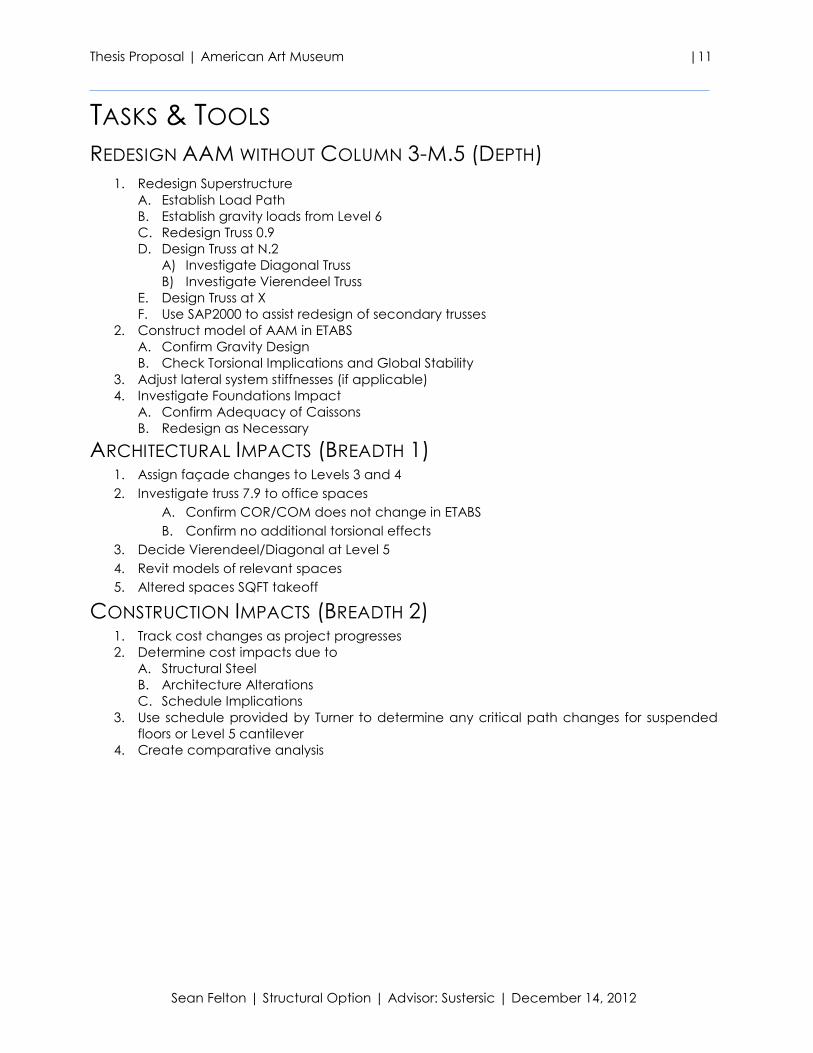
TASKS & TOOLS
REDESIGN AAM WITHOUT COLUMN 3-M.5 (DEPTH)
1. Redesign Superstructure
A. Establish Load Path
B. Establish gravity loads from Level 6
C. Redesign Truss 0.9
D. Design Truss at N.2
A) Investigate Diagonal Truss
B) Investigate Vierendeel Truss
E. Design Truss at X
F. Use SAP2000 to assist redesign of secondary trusses
2. Construct model of AAM in ETABS
A. Confirm Gravity Design
B. Check Torsional Implications and Global Stability
3. Adjust lateral system stiffnesses (if applicable)
4. Investigate Foundations Impact
A. Confirm Adequacy of Caissons
B. Redesign as Necessary
ARCHITECTURAL IMPACTS (BREADTH 1) 1. Assign façade changes to Levels 3 and 4
2. Investigate truss 7.9 to office spaces
A. Confirm COR/COM does not change in ETABS
B. Confirm no additional torsional effects
3. Decide Vierendeel/Diagonal at Level 5
4. Revit models of relevant spaces
5. Altered spaces SQFT takeoff
CONSTRUCTION IMPACTS (BREADTH 2) 1. Track cost changes as project progresses
2. Determine cost impacts due to
A. Structural Steel
B. Architecture Alterations
C. Schedule Implications
3. Use schedule provided by Turner to determine any critical path changes for suspended
floors or Level 5 cantilever
4. Create comparative analysis
Thesis Proposal | American Art Museum |12
Sean Felton | Structural Option | Advisor: Sustersic | December 14, 2012
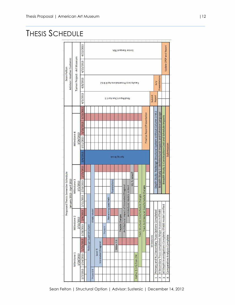
THESIS SCHEDULE
Thesis Proposal | American Art Museum |13
Sean Felton | Structural Option | Advisor: Sustersic | December 14, 2012
CONCLUSION This proposal presents an alternative structural design which does not include the use of a column
at the location of 3-M.5. In order to accommodate this provision, large gravity trusses will be
added to redistribute the weight carried by the missing column. The trusses cannot simply be
hidden behind walls, so the architecture will require adequate attention. Changes will be made
to the façade on two levels, and to the language between public and office spaces. Finally, a
comparative cost and schedule analysis will be performed to analyze the impact on the
construction of the building. This data will be presented in contrast to the current design and
construction schedules to evaluate the options and verify the use of Column 3-M.5 as the best
possible method for AAM’s design.