amendment to request for proposals air-cooled … · please provide elevation drawings of the acc,...
TRANSCRIPT
103 Administrative Services Center 3295 College Road
Phone (907) 474-7315 Fax (907) 474-7720
Procurement & Contract Services PO Box 757940, Fairbanks, Alaska 99775-7940, www.uaf.edu/procurement/
AMENDMENT TO REQUEST FOR PROPOSALS Air-Cooled Condensing System
REQUEST FOR PROPOSALS #15P0015MG AMENDMENT NO. 1 Procurement Officer: Michael Grahek Effective Date: January 22, 2015 Issue Date: January 6, 2015
ISSUED TO: ISSUED BY: All Prospective Offerors University of Alaska Fairbanks Procurement & Contract Services PO Box 757940 Fairbanks AK 99775-7940
Dear Vendor:
The following clarifications, revisions, and changes have been made to Request for Proposals No. 15P0015MG for an Air-Cooled Condensing System:
QUESTIONS: The following questions were received from potential Offerors. They are presented in a Question and Answer format.
A1-Q1) Please provide elevation drawings of the ACC, condensate tank, surface condenser and steam duct such that the draining capability and the location of the surface condenser can be determined.
A1-A1) Reference sketch SK-M-001 included in Attachment 2 of this Amendment.
A1-Q2) Please provide the thermal design requirements of the surface condenser. Additionally, the corresponding cooling water temperature and flow are required.
A1-A2) Thermal design conditions have been added to Section 00 43 33 – Proposed Products Form. The remainder of the design requirements can be found in Section 48 11 16 – Surface Condenser. Reference Attachment 1.
A1-Q3) Please clarify the desired start-up and holding operation vacuum equipment. For Start-up we believe you are requiring a single steam jet air ejector. For holding operation it seems that both vacuum pumps and two-stage steam jet air ejectors are specified. In this case we would expect either LRVPs or SJAEs, but not both. Your clarification is appreciated.
A1-A3) As stated in the Pre-Proposal Conference, UAF desires a vacuum system consisting of the following:
• One Steam Hogger • One 100% duty Liquid Ring Vacuum Pump designed for holding service • One 100% duty Steam Jet Air Ejector designed for holding service
A1-Q4) Alaska Business License – Is an ABL required, or is it needed only as part of the “Alaska bidder” qualification?
A1-A4) An Alaska Business License is not required to submit a proposal. However, in order to be eligible for Alaska Bidder preferences as may be applicable, an Offeror must have one at the deadline for proposal submittal, and in any event the successful Offeror must have one before it may be awarded a contract.
DocuSign Envelope ID: D198A175-393C-4DCB-8A41-EB96BF4231C0
University of Alaska Fairbanks Page 2 RFP No. 15P0015MG - Amendment No. 1
A1-A4) An Alaska Business License is not required to submit a proposal. However, in order to be eligible for Alaska Bidder preferences as may be applicable, an Offeror must have one at the deadline for proposal submittal, and in any event the successful Offeror must have one before it can be awarded a contract.
A1-Q5) Is the evaporative cooling tower a part of this scope? If so, are there specific requirements?
A1-A5) The basis of design originally called for a parallel condensing system. However, the system was revised to consist of only an ACC and a heat recovery surface condenser (no wet cooling tower). References to wet cooling towers and parallel condensing systems have been removed from the text. The sections that have been impacted are included in Attachment 1 of this Amendment.
A1-Q6) Please consider a substitution request for the use of Hansen gearboxes.
A1-A6) The use of Hansen gearboxes is hereby approved.
A1-Q7) Please consider a substitution request for the use of Unique Systems vacuum pumps.
A1-A7) The use of Hansen gearboxes is hereby disallowed. UAF has pre-approved multiple vacuum pump manufacturers and is not sufficiently familiar with Unique to grant approval at this time.
A1-Q8) Please consider a substitution request for the use of Lafavorite expansion joints.
A1-A8) The use of Lafavorite expansion joints is hereby approved.
CLARIFICATIONS:
A1-C1) Noise requirements have been added to Paragraph 2.23 of Section 48 11 17 – Air Cooled Condensers. Additionally, a noise guarantee table has been added to Section 00 43 33 – Proposed Products Form for completion by each offeror.
A1-C2) Section 01 10 00, Paragraph 1.08.B Anticipated Schedule, has been revised for clarity and to remove information that was present in the front-end documents. Additional dates will be provided once the anticipated construction schedule for the ACC is developed by the general contractor.
ATTACHMENTS: The following Attachments are provided and incorporated into the RFP:
• Attachment 1 – Updated Technical Specifications o 00 43 33 Proposed Product Form (Datasheets) o 01 10 00 Summary o 01 32 19 Submittal Schedule o 01 86 36 Condensing System Performance Requirements o 48 11 16 Surface Condenser o 48 11 17 Air Cooled Condenser
• Attachment 2 – SK-M-001 Air-Cooled Condenser Equipment Arrangement Sketch
All other terms and conditions remain the same.
Sincerely,
UNIVERSITY OF ALASKA FAIRBANKS
Michael Grahek, C.P.M. Sr. Contracting Officer
DocuSign Envelope ID: D198A175-393C-4DCB-8A41-EB96BF4231C0
23875.20.10dv126
PROPOSED PRODUCTS FORMSECTION 00 43 33 - Instructions and Notes - Page 1
Rev. 0
a)
b)c)d)e)
a)
b)
c)
Instructions for Data Tables:
Data sheets may require information not known until Seller’s engineering is complete. Furnish estimated values based on good engineering judgment. Estimated values shall be identified by placement of “(est.)” next to value.
Bidder shall adhere to required operating conditions when provided in the Spec Data column. Bidders may provide predicted conditions that are below a stated maximum or above a stated minimum.Conditions marked as “By Seller” in the Spec Data column have no specific performance requirement. The Bidder shall provide this information based on their predicted performance calculations.
Do not leave items blank or labeled “To Be Determined” or “Later.”Include the term "(est.)" or similar for items that contain preliminary or estimated data.Do not submit Seller Product Data instead of completed data sheets.
Instructions for Guarantee Sheets:
Bidder guarantees performance at the values which are entered in Guaranteed Performance Sheets Provided by Seller.
Provide a datasheet for each type of motor and each type of VFD being offered.
University of Alaska Fairbanks RFP No. 15P0015MG - Amendment No. 1 Attachment 1DocuSign Envelope ID: D198A175-393C-4DCB-8A41-EB96BF4231C0
23875.20.10 PROPOSED PRODUCTS FORMSECTION 00 43 33 - Guarantees - Page 2
AIR COOLED CONDENSER
DATASHEET
DESCRIPTION Units SPEC DATA VENDOR DATA
GUARANTEE CONDITIONS1. Ambient Air Dry Bulb Temperature °F 932. Barometric Pressure psia 14.443. Steam Turbine Exhaust Pressure in HgA 104. Steam Turbine Exhaust Mass Flowrate kpph 126,1075. Steam Turbine Exhaust Enthalpy BTU/lb 10776. Steam Turbine Exhaust Temperature °F 125.47. Steam Turbine Exhaust Energy BTU/s 37,7288. Site Elevation Above Sea Level Ft 437.89. Auxiliary Power Consumption* kW By Seller
AIR COOLED CONDENSER
DATASHEET
DESCRIPTION Units SPEC DATA VENDOR DATA
GUARANTEE CONDITIONS1. Ambient Air Dry Bulb Temperature °F 402. Barometric Pressure psia 14.443. Steam Turbine Exhaust Pressure in HgA 44. Steam Turbine Exhaust Mass Flowrate kpph 126,1075. Steam Turbine Exhaust Enthalpy BTU/lb 1012.36. Steam Turbine Exhaust Temperature °F 161.47. Steam Turbine Exhaust Energy BTU/s 35,4598. Site Elevation Above Sea Level Ft 437.89. Auxiliary Power Consumption* kW By Seller
AIR COOLED CONDENSER
DATASHEET
DESCRIPTION Units SPEC DATAOPERATING RANGE (by Engineer)
1. Extreme Maximum Ambient Air Dry Bulb Temperature °F 93 N/A
2. Extreme Minimum Ambient Air Dry Bulb Temperature °F -66 N/A
Equipment Name:Air Cooled Condenser 33-ACC-
ACCU-001
Equipment Name:Air Cooled Condenser 33-ACC-
ACCU-001
GUARANTEE DESIGN OPERATING CONDITIONS (by Engineer)
CONDITIONS
Equipment Name:Air Cooled Condenser 33-ACC-
ACCU-001
GUARANTEE DESIGN OPERATING CONDITIONS (by Engineer)
University of Alaska Fairbanks RFP No. 15P0015MG - Amendment No. 1 Attachment 1DocuSign Envelope ID: D198A175-393C-4DCB-8A41-EB96BF4231C0
23875.20.10 PROPOSED PRODUCTS FORMSECTION 00 43 33 - Guarantees - Page 3
3. Maximum Continuous Steam Turbine Exhaust Mass Flowrate kpph 126,107 N/A
5. Steam Turbine Alarm in HgA 12 N/A6. Steam Turbine Alarm °F 169 N/A7. Steam Turbine Trip in HgA 15 N/A8. Steam Turbine Trip °F 179 N/A
AIR COOLED CONDENSER
DATASHEET
DESCRIPTION Units SPEC DATA VENDOR DATA
1. Total Fan Power Referred to Motor Input Side kW By Seller
2. Maximum Sound Pressure Level at 3 feet from perimeter of ACC dBA By Seller
3. Turbine Exhaust Pressure (measured at turbine exhaust flange) in HgA By Seller
3. Minimum Continuous Steam Turbine Exhaust Mass Flowrate to Prevent Freezing kpph By Seller
4. Heat Rejection Rate btu/hr By Seller6. Auxiliary Steam Consumption** lb/hr By Seller
*Auxiliary power consumption listed here shall be for the entire condensing system and associated equipment.** Auxiliary steam consumption listed here shall be for the SJAE (Holding)
CONDENSER DATA SHEET
DESCRIPTION SPEC DATA VENDOR DATA
Manufacturer N/A
Steam flow lb/hr By SellerSteam exhaust enthalpy btu/lb By SellerCondenser pressure in. Hg. Same as ACCCirculating water flow required gpm 770Circulating water inlet design temperature ºF 42Circulating water outlet design temperature ºF 97Circulating water pressure drop ft <24*
Avg. circulating water tube velocity ft/sec 8.0 Max
Heat rejected to chilled water at design flow btu/sec By SellerCleanliness factor % 85
OPERATING CONDITIONS
Equipment Name:Air Cooled Condenser 33-ACC-
ACCU-001
GUARANTEED DESIGN PERFORMANCE (by Supplier)
Equipment Name: CONDENSER
Tag No.: 33-ACC-CND-001Units
University of Alaska Fairbanks RFP No. 15P0015MG - Amendment No. 1 Attachment 1DocuSign Envelope ID: D198A175-393C-4DCB-8A41-EB96BF4231C0
23875.20.10 PROPOSED PRODUCTS FORMSECTION 00 43 33 - Guarantees - Page 4
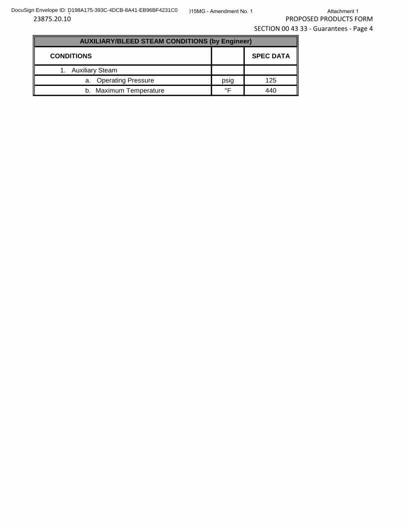
CONDITIONS SPEC DATA
1. Auxiliary Steama. Operating Pressure psig 125b. Maximum Temperature °F 440
AUXILIARY/BLEED STEAM CONDITIONS (by Engineer)
University of Alaska Fairbanks RFP No. 15P0015MG - Amendment No. 1 Attachment 1DocuSign Envelope ID: D198A175-393C-4DCB-8A41-EB96BF4231C0
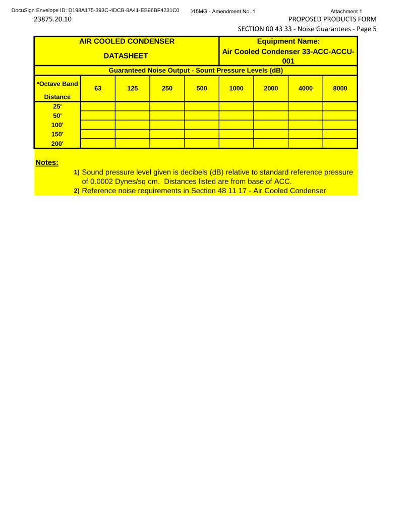
23875.20.10 PROPOSED PRODUCTS FORMSECTION 00 43 33 - Noise Guarantees - Page 5
*Octave Band
Distance25'50'
100'150'200'
Notes:1) Sound pressure level given is decibels (dB) relative to standard reference pressure
of 0.0002 Dynes/sq cm. Distances listed are from base of ACC.2) Reference noise requirements in Section 48 11 17 - Air Cooled Condenser
Air Cooled Condenser 33-ACC-ACCU-001
Equipment Name:AIR COOLED CONDENSER
DATASHEET
1000 2000 4000 8000
Guaranteed Noise Output - Sount Pressure Levels (dB)
63 125 250 500
University of Alaska Fairbanks RFP No. 15P0015MG - Amendment No. 1 Attachment 1DocuSign Envelope ID: D198A175-393C-4DCB-8A41-EB96BF4231C0
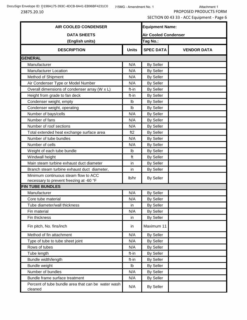
23875.20.10 PROPOSED PRODUCTS FORMSECTION 00 43 33 - ACC Equipment - Page 6
DESCRIPTION Units SPEC DATA VENDOR DATA
Manufacturer N/A By SellerManufacturer Location N/A By SellerMethod of Shipment N/A By SellerAir Condenser Type or Model Number N/A By SellerOverall dimensions of condenser array (W x L) ft-in By SellerHeight from grade to fan deck ft-in By SellerCondenser weight, empty lb By SellerCondenser weight, operating lb By SellerNumber of bays/cells N/A By SellerNumber of fans N/A By SellerNumber of roof sections N/A By SellerTotal extended heat exchange surface area ft2 By SellerNumber of tube bundles N/A By SellerNumber of cells N/A By SellerWeight of each tube bundle lb By SellerWindwall height ft By SellerMain steam turbine exhaust duct diameter in By SellerBranch steam turbine exhaust duct diameter, in By SellerMinimum continuous steam flow to ACC necessary to prevent freezing at -60 °F lb/hr By Seller
Manufacturer N/A By SellerCore tube material N/A By SellerTube diameter/wall thickness in By SellerFin material N/A By SellerFin thickness in By Seller
Fin pitch, No. fins/inch in Maximum 11
Method of fin attachment N/A By SellerType of tube to tube sheet joint N/A By SellerRows of tubes N/A By SellerTube length ft-in By SellerBundle width/length ft-in By SellerBundle weight lb By SellerNumber of bundles N/A By SellerBundle frame surface treatment N/A By SellerPercent of tube bundle area that can be water wash cleaned N/A By Seller
FIN TUBE BUNDLES
(English units) Tag No.:
GENERAL
AIR COOLED CONDENSER
DATA SHEETS
Equipment Name:
Air Cooled Condenser
University of Alaska Fairbanks RFP No. 15P0015MG - Amendment No. 1 Attachment 1DocuSign Envelope ID: D198A175-393C-4DCB-8A41-EB96BF4231C0
23875.20.10 PROPOSED PRODUCTS FORMSECTION 00 43 33 - ACC Equipment - Page 7
Manufacturer N/A By SellerFan blade material N/A By SellerFan diameter ft-in By SellerNumber of blades per fan N/A By SellerFan rpm, high speed/low speed rpm By SellerFan tip speed N/A By SellerFan shaft power, high speed/low speed hp By Seller
Manufacturer N/A By Seller (per 01 63 00)
Model no. N/A By SellerType N/A By SellerReduction ratio N/A By SellerAGMA service factor (refer to motor nameplate rating) N/A By Seller
Pressure required to rupture disc psia By SellerNumber provided N/A By SellerManufacturer N/A By Seller
Make and Type N/A By SellerMaterial N/A By SellerEnd Preparation N/A By Seller
Manufacturer N/A By Seller (per 01 63 00)
Quantity N/A By SellerType N/A By SellerFlow rate, GPM gpm By SellerEfficiency, % % By Seller
Manufacturer N/A By SellerModel no., size N/A By SellerNumber of Stages N/A By SellerCapacity per Train scfm By SellerSteam Consumption lb/hr By SellerMotive Steam Pressure psig 125Motive Steam Temperature F 400Materials of Construction N/A By Seller
Ejectors N/A By SellerCondenser Shell N/A By SellerCondenser Tubes N/A By Seller
Dimensions LxWxH ft By Seller
FANS
GEAR DRIVES
RUPTURE DISCS
EXHAUST NECK EXPANSION JOINT
DRAIN PUMPS
STEAM JET AIR EJECTOR (HOLDING)
University of Alaska Fairbanks RFP No. 15P0015MG - Amendment No. 1 Attachment 1DocuSign Envelope ID: D198A175-393C-4DCB-8A41-EB96BF4231C0
23875.20.10 PROPOSED PRODUCTS FORMSECTION 00 43 33 - ACC Equipment - Page 8
Operating Weight lb By SellerSkid Mounted N/A Yes
Manufacturer N/A By SellerModel no., size N/A By SellerNumber of Stages N/A By SellerCapacity per Train scfm By SellerSteam Consumption lb/hr By SellerMotive Steam Pressure psig 125Motive Steam Temperature F 400Materials of Construction N/A By Seller
Ejectors N/A By SellerCondenser Shell N/A By SellerCondenser Tubes N/A By Seller
Dimensions LxWxH ft By SellerOperating Weight lb By SellerSkid Mounted N/A Yes
Manufacturer N/A By SellerNumber of pumps N/A By SellerCapacity per pump N/A By SellerPower consumption per pump hp By SellerPressure maintained in. Hg. By SellerTotal fluid evacuated lb/hr By SellerDry air evacuated lb/hr By SellerSealing Fluid By Seller Design inlet temperature ºF By Seller Maximum discharge temperature ºF By Seller Type of fluid By Seller Fluid density lb/ft3 By Seller Vapor Pressure psia By SellerOverall vacuum pump skid length ft-inOverall vacuum pump skid width ft-inOverall vacuum pump skid height ft-inVacuum pump skid weight: lb
Manufacturer N/A By Seller (per 01 63 00)
Quantity N/A By Seller
Manufacturer N/A By Seller (per 01 63 00)
Quantity N/A By Seller
VACUUM PUMP DESIGN
MOTOR OPERATED VALVES
LOUVERS
STEAM JET AIR EJECTOR (HOGGING)
University of Alaska Fairbanks RFP No. 15P0015MG - Amendment No. 1 Attachment 1DocuSign Envelope ID: D198A175-393C-4DCB-8A41-EB96BF4231C0
23875.20.10 PROPOSED PRODUCTS FORMSECTION 00 43 33 - ACC Equipment - Page 9
Total Face Area ft2 By SellerPressure Drop at Design Conditions inH20 By Seller
Manufacturer N/A By Seller (per 01 63 00)
Power consumption kW By Seller
Supplier N/A By Seller (per 01 63 00)
Quantity tons By Seller
1) Air Side Performance N/A By Seller a. Total net tube bundle face area, square feet ft2 By Seller b. Total fan air flow, (all cells) acfm By Seller c. Air flow velocities ft/sec By Seller 1. At air inlet perimeter ft/sec By Seller 2. Face velocity entering fin tube bundle ft/sec By Seller d. Pressure Drops N/A By Seller 1. Air inlet to fan bell inlet in. Hg. By Seller 2. Across fan guard screen and fan bridge in. Hg. By Seller 3. Dynamic loss in. Hg. By Seller 4. Across bundles in. Hg. By Seller 5. Natural Draft in. Hg. By Seller 6. Turning loss (entering and exiting fin tube bundle) in. Hg. By Seller
7. Additional losses in. Hg. By Seller 8. Total static pressure loss in. Hg. By Seller2) Condensate Flow By Seller a. Maximum dissolved O2 level ppb By Seller b. Non-condensable gas (NCG) N/A By Seller 1. Design Flow lb/hr By Seller 2. Minimum Flow lb/hr By Seller 3. Maximum Flow lb/hr By Seller c. NCG Maximum Exit Temperature, °F °F By Seller d. NCG Exit Pressure, in HgA in. Hg. By Seller e. Air Inleakage, lb/hr lb/hr By Seller
f. Maximum nondeaerated condensate makeup gpm By Seller
g. Hotwell subcooling at design conditions °F By Seller
Estimated man hours for field erection hours By SellerField welding required, size and length linear ft By SellerNumber of sections as shipped N/A By SellerLargest Section:
ERECTION DATA
OTHER OPERATING CONDITIONS
STEEL
LOUVER ACTUATORS
University of Alaska Fairbanks RFP No. 15P0015MG - Amendment No. 1 Attachment 1DocuSign Envelope ID: D198A175-393C-4DCB-8A41-EB96BF4231C0

23875.20.10 PROPOSED PRODUCTS FORMSECTION 00 43 33 - ACC Equipment - Page 10
Dimensions ft x ft x ft By Seller Weight lb By Seller
University of Alaska Fairbanks RFP No. 15P0015MG - Amendment No. 1 Attachment 1DocuSign Envelope ID: D198A175-393C-4DCB-8A41-EB96BF4231C0
23875.20.10 PROPOSED PRODUCTS FORMSECTION 00 43 33 - Condenser Equipment - Page 11
DESCRIPTION Units SPEC DATA VENDOR DATA
CONDENSER TUBE DESIGN
Total effective surface area ft2 By Seller
Number of passes N/A 2
Number of tubes N/A By Seller
Tube material N/A By Seller
Tube outside diameter in By Seller
Tube inside diameter in By Seller
Tube wall thickness in By Seller
Tube length ft By Seller
Tube pitch in By Seller
Tube design pressure: psig By Seller
Tube design temperature ºF By Seller
Tube support spacing ft 5’ Max
Condenser tube thermal conductivity btu-in./hr-ft-°F By Seller
Condenser fouling factor(btu-in./hr-
ft2-°F)-1 By Seller
Condenser external h.t.c./Laminar film h.t.c. N/A By Seller
Condensate sub cooling ºF 0
Computed external h.t.c. (btu-in./hr-ft2-°F) By Seller
Computed external h.t.c. (btu-in./hr-ft2-°F) By Seller
Computed overall h.t.c. (btu-in./hr-ft2-°F) By Seller
Computed overall UA btu-in./sec-°F By Seller
Internal Reynolds Number N/A By Seller
Water Prandtl Number N/A By Seller
Internal Nusselt Number N/A By Seller
Water box design pressure psig 75
CONDENSER SHELL DESIGN
CONDENSER Equipment Name: CONDENSER
DATA SHEETTag No.:
University of Alaska Fairbanks RFP No. 15P0015MG - Amendment No. 1 Attachment 1DocuSign Envelope ID: D198A175-393C-4DCB-8A41-EB96BF4231C0
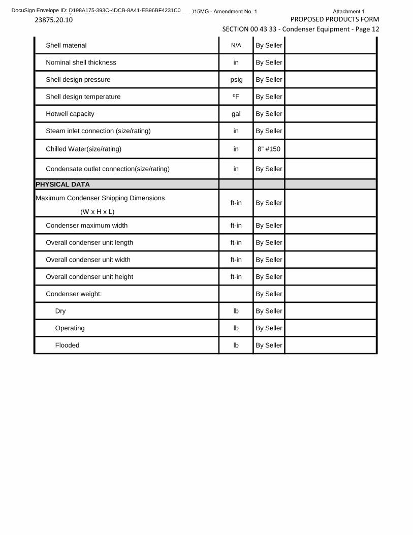
23875.20.10 PROPOSED PRODUCTS FORMSECTION 00 43 33 - Condenser Equipment - Page 12
Shell material N/A By Seller
Nominal shell thickness in By Seller
Shell design pressure psig By Seller
Shell design temperature ºF By Seller
Hotwell capacity gal By Seller
Steam inlet connection (size/rating) in By Seller
Chilled Water(size/rating) in 8” #150
Condensate outlet connection(size/rating) in By Seller
PHYSICAL DATA
Maximum Condenser Shipping Dimensions
(W x H x L)
Condenser maximum width ft-in By Seller
Overall condenser unit length ft-in By Seller
Overall condenser unit width ft-in By Seller
Overall condenser unit height ft-in By Seller
Condenser weight: By Seller
Dry lb By Seller
Operating lb By Seller
Flooded lb By Seller
ft-in By Seller
University of Alaska Fairbanks RFP No. 15P0015MG - Amendment No. 1 Attachment 1DocuSign Envelope ID: D198A175-393C-4DCB-8A41-EB96BF4231C0
23875.20.10dv126
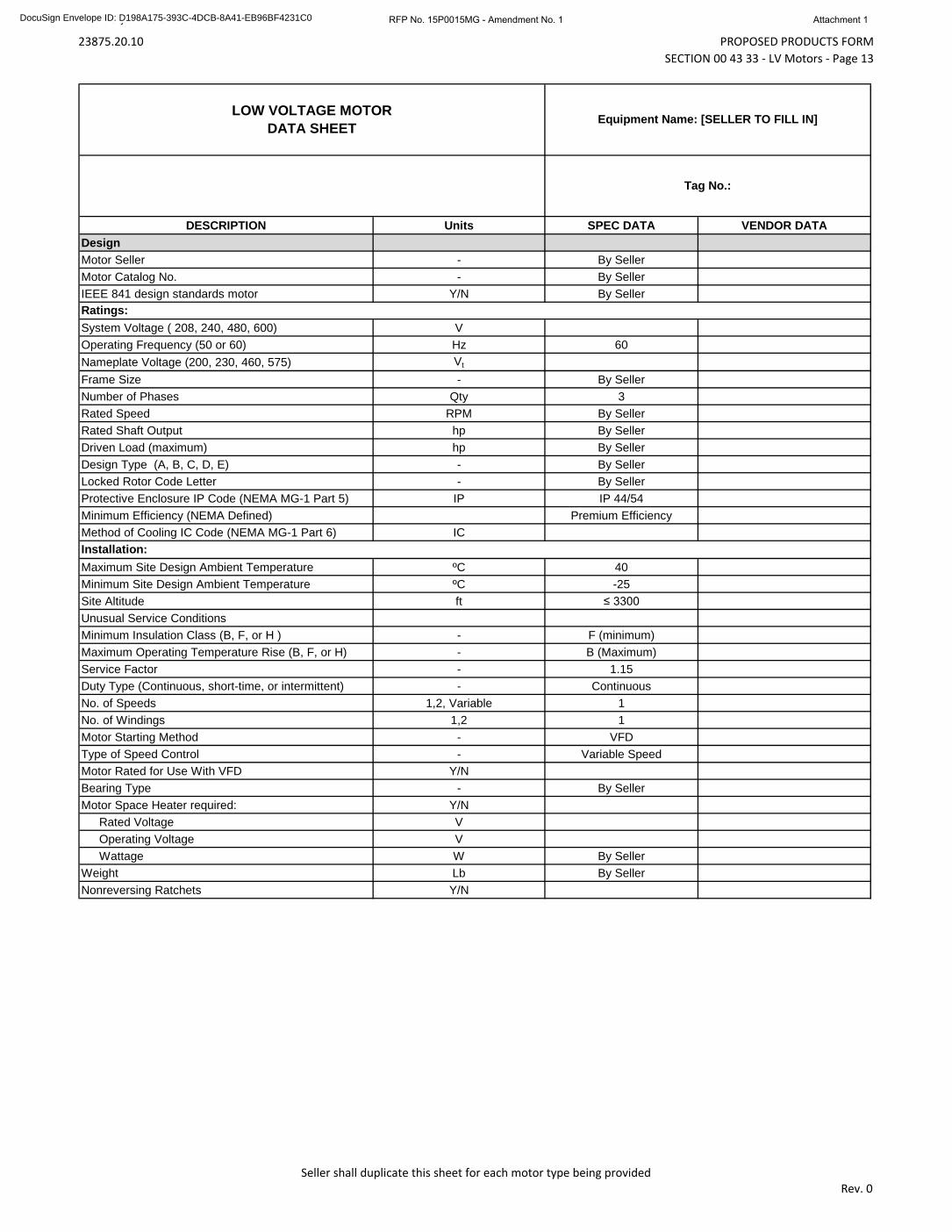
PROPOSED PRODUCTS FORMSECTION 00 43 33 - LV Motors - Page 13
Seller shall duplicate this sheet for each motor type being providedRev. 0
DESCRIPTION Units SPEC DATA VENDOR DATADesignMotor Seller - By SellerMotor Catalog No. - By SellerIEEE 841 design standards motor Y/N By Seller
System Voltage ( 208, 240, 480, 600) VOperating Frequency (50 or 60) Hz 60Nameplate Voltage (200, 230, 460, 575) Vt
Frame Size - By SellerNumber of Phases Qty 3Rated Speed RPM By SellerRated Shaft Output hp By SellerDriven Load (maximum) hp By SellerDesign Type (A, B, C, D, E) - By SellerLocked Rotor Code Letter - By SellerProtective Enclosure IP Code (NEMA MG-1 Part 5) IP IP 44/54Minimum Efficiency (NEMA Defined) Premium EfficiencyMethod of Cooling IC Code (NEMA MG-1 Part 6) IC
Maximum Site Design Ambient Temperature ºC 40Minimum Site Design Ambient Temperature ºC -25Site Altitude ft ≤ 3300Unusual Service ConditionsMinimum Insulation Class (B, F, or H ) - F (minimum)Maximum Operating Temperature Rise (B, F, or H) - B (Maximum)Service Factor - 1.15Duty Type (Continuous, short-time, or intermittent) - ContinuousNo. of Speeds 1,2, Variable 1No. of Windings 1,2 1Motor Starting Method - VFDType of Speed Control - Variable SpeedMotor Rated for Use With VFD Y/NBearing Type - By SellerMotor Space Heater required: Y/N
Rated Voltage VOperating Voltage VWattage W By Seller
Weight Lb By SellerNonreversing Ratchets Y/N
Installation:
Ratings:
LOW VOLTAGE MOTORDATA SHEET
Equipment Name: [SELLER TO FILL IN]
Tag No.:
University of Alaska Fairbanks RFP No. 15P0015MG - Amendment No. 1 Attachment 1DocuSign Envelope ID: D198A175-393C-4DCB-8A41-EB96BF4231C0
23875.20.10dv126
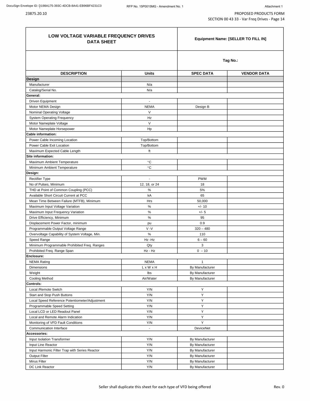
PROPOSED PRODUCTS FORMSECTION 00 43 33 - Var Freq Drives - Page 14
Seller shall duplicate this sheet for each type of VFD being offered Rev. 0
DESCRIPTION Units SPEC DATA VENDOR DATADesign
Manufacturer N/aCatalog/Serial No. N/a
Driven Equipment -Motor NEMA Design NEMA Design BNominal Operating Voltage VSystem Operating Frequency HzMotor Nameplate Voltage VMotor Nameplate Horsepower Hp
Power Cable Incoming Location Top/BottomPower Cable Exit Location Top/BottomMaximum Expected Cable Length ft
Maximum Ambient Temperature °CMinimum Ambient Temperature °C
Rectifier Type - PWMNo of Pulses, Minimum 12, 18, or 24 18THD at Point of Common Coupling (PCC) % 5%Available Short Circuit Current at PCC kA 65Mean Time Between Failure (MTFB), Minimum Hrs 50,000Maximum Input Voltage Variation % +/- 10Maximum Input Frequency Variation % +/- 5Drive Efficiency, Minimum % 95Displacement Power Factor, minimum pu 0.9Programmable Output Voltage Range V -V 320 – 480Overvoltage Capability of System Voltage, Min. % 110Speed Range Hz -Hz 6 – 60Minimum Programmable Prohibited Freq. Ranges Qty 3Prohibited Freq. Range Span Hz - Hz 0 – 10
NEMA Rating NEMA 1Dimensions L x W x H By ManufacturerWeight lbs By ManufacturerCooling Method Air/Water By Manufacturer
Local /Remote Switch Y/N YStart and Stop Push Buttons Y/N YLocal Speed Reference Potentiometer/Adjustment Y/N YProgrammable Speed Setting Y/N YLocal LCD or LED Readout Panel Y/N YLocal and Remote Alarm Indication Y/N YMonitoring of VFD Fault Conditions Y/N YCommunication Interface - DeviceNet
Input Isolation Transformer Y/N By ManufacturerInput Line Reactor Y/N By ManufacturerInput Harmonic Filter Trap with Series Reactor Y/N By ManufacturerOutput Filter Y/N By ManufacturerMirus Filter Y/N By ManufacturerDC Link Reactor Y/N By Manufacturer
Enclosure:
Controls:
Accessories:
LOW VOLTAGE VARIABLE FREQUENCY DRIVESDATA SHEET
Equipment Name: [SELLER TO FILL IN]
Tag No.:
General:
Cable information:
Site information:
Design:
University of Alaska Fairbanks RFP No. 15P0015MG - Amendment No. 1 Attachment 1DocuSign Envelope ID: D198A175-393C-4DCB-8A41-EB96BF4231C0
23875.20.10dv126
PROPOSED PRODUCTS FORMSECTION 00 43 33 - Var Freq Drives - Page 15
Seller shall duplicate this sheet for each type of VFD being offered Rev. 0
Special Accessories Required (Provide list) Y/N By Manufacturer
University of Alaska Fairbanks RFP No. 15P0015MG - Amendment No. 1 Attachment 1DocuSign Envelope ID: D198A175-393C-4DCB-8A41-EB96BF4231C0
23875.20.10dv126
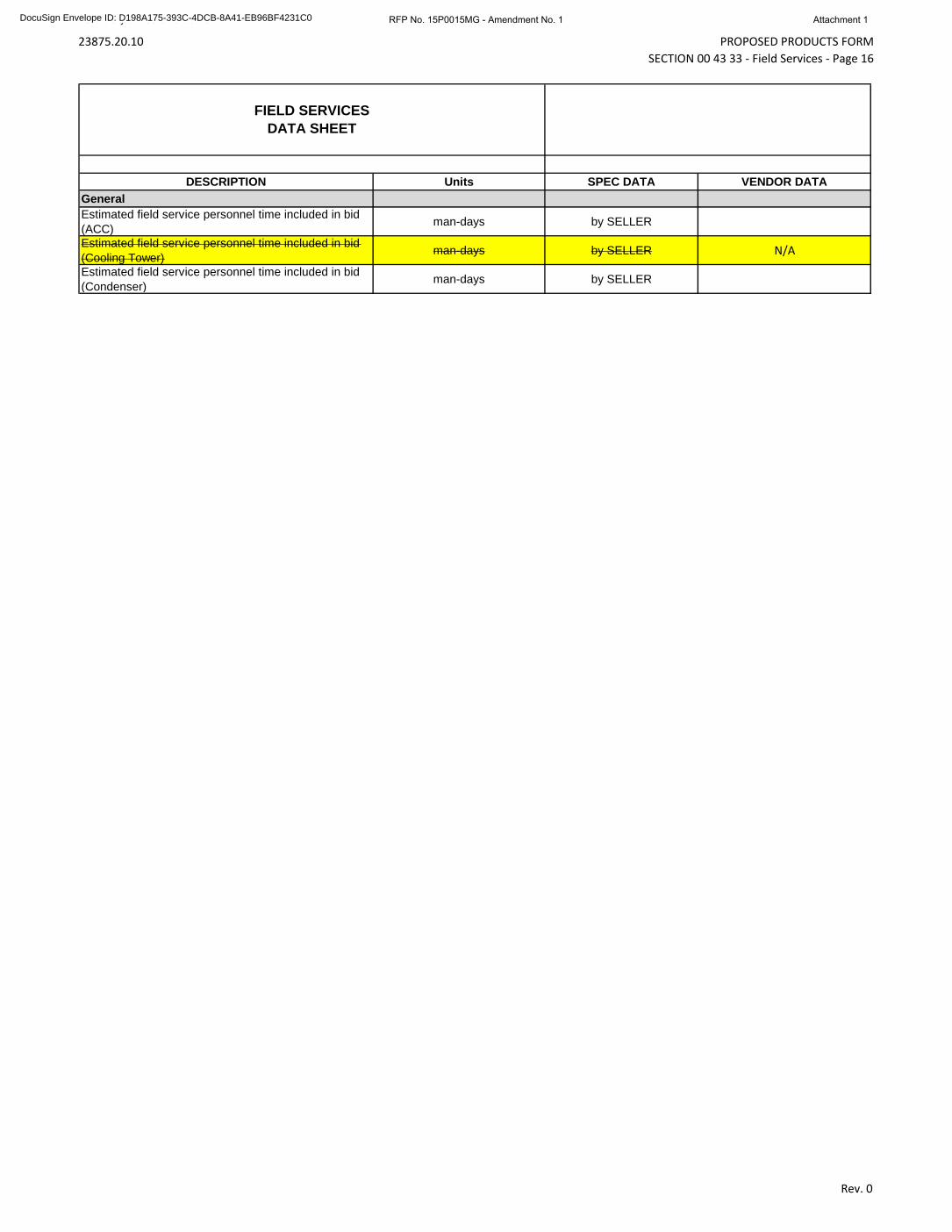
PROPOSED PRODUCTS FORMSECTION 00 43 33 - Field Services - Page 16
Rev. 0
DESCRIPTION Units SPEC DATA VENDOR DATAGeneralEstimated field service personnel time included in bid (ACC) man-days by SELLER
Estimated field service personnel time included in bid (Cooling Tower) man-days by SELLER N/A
Estimated field service personnel time included in bid (Condenser) man-days by SELLER
FIELD SERVICESDATA SHEET
University of Alaska Fairbanks RFP No. 15P0015MG - Amendment No. 1 Attachment 1DocuSign Envelope ID: D198A175-393C-4DCB-8A41-EB96BF4231C0
23875.20.10 SUMMARY SECTION 01 10 00 - Page 1
PART 1 GENERAL
1.01 USE OF TECHNICAL SPECIFICATIONS FOR BIDDING PURPOSES
A. The technical specifications provided in this Annex (Annex A) are intended to define the required scope of this contract and to indicate a representative level of quality that the Buyer will require from the Seller.
B. The technical specifications have been intentionally written to be generic in nature so as not to indicate a preference for one Seller over another.
C. The Buyer encourages each Seller to submit their standard design that best fits the performance requirements identified in Section 00 43 33 of this RFP.
D. Deviations between the Seller’s standard design and the design called for in this RFP shall be detailed as a clarification in the Seller’s proposal. 1. The Seller is encouraged to highlight and expand upon these clarifications in attachments to their
proposal. Additional details should be provided for any clarification that the Seller feels would bring significant benefit to the Buyer in terms of capital cost, ease of installation/erection, efficiency, ease of operation, reduced maintenance, or extended operational life.
E. Sellers will not be penalized for clarifications that, in the opinion of the Buyer, are necessary to allow the Seller to propose their standard design.
F. The Buyer requests that the Sellers adhere to any technical requirements that will not directly impact the Seller’s standard design. This includes quality requirements, approved vendors, design minimums, design maximums, requirements for commodities (pipe, wire, steel, conduit) and associated components, and types of major auxiliary equipment such as motors, electrical gear, fans, and gland steam condenser.
G. These technical specifications will be conformed to match the winning Seller’s scope of supply prior to contract signing.
1.02 PROJECT BACKGROUND
A. The existing coal boilers in the Ben Atkinson Heat and Power Plant, located on the University of Alaska Fairbanks (“UAF” or “the University”) campus in Fairbanks, Alaska, were constructed in 1964 and require either significant renewal or replacement to continue to provide heat and power to the University campus. UAF has made the decision to replace the existing coal boilers and auxiliary equipment with a new combined heat and power plant that will be fueled with a combination of coal and biomass.
1.03 PROJECT DESCRIPTION
A. The project consists of the installation of two new coal-fired CFB Boilers to replace and augment existing steam generation capacity. The boilers shall also be capable of co-firing up to 15% biomass. The two existing coal-fired, stoker-type boilers will be decommissioned upon startup of the new boilers. The replacement project also includes the installation of a new 22 MW (gross) steam turbine-generator (STG), an air-cooled condenser heat rejection system, required auxiliary equipment, and process and utility connections to the existing facility. The equipment procured for this project will be housed in a new facility consisting of a boiler building, a turbine building, and an administration building in adjoining structures.
B. The project intends to use the Air Cooled Condenser (ACC) to condense the maximum amount of exhaust steam from the turbine at the extreme minimum to extreme maximum ambient temperatures, defined in Section 00 43 33. The ACC system will work to achieve the required backpressure as defined in Section 00 43 33 and Section 01 86 36.
University of Alaska Fairbanks RFP No. 15P0015MG - Amendment No. 1 Attachment 1DocuSign Envelope ID: D198A175-393C-4DCB-8A41-EB96BF4231C0
23875.20.10 SUMMARY SECTION 01 10 00 - Page 2 1.04 WORK COVERED BY CONTRACT DOCUMENTS
A. Work of this Agreement comprises design, procurement, manufacture, and delivery to the job site of the Air Cooled Condenser for The University of Alaska Fairbanks Coal-Fired Boiler Replacement Project located on the university campus in Fairbanks, Alaska. Work under this contract includes, but is not limited to, the items identified in this Section and in the following documents: 1. Terminal Points list (TP) as delineated in Section 01 18 00 2. Division of Responsibility (DOR) as delineated in Section 01 11 00
B. Work on Project identified as being supplied by others will be executed under separate contracts, and is excluded from this Agreement. Reference Paragraph 1.06 of this Section and the Division of Responsibility (DOR) provided in Section 01 11 00
1.05 GENERAL SCOPE OF SUPPLY
A. Design, manufacture, and deliver one air cooled condenser and steam surface condenser. Auxiliary components for proper operation, function, control, and monitoring of units shall be included. Units shall be fully compatible and matched with electric generator and accessories.
B. Structural Components: 1. Structural steel for skidded components and means for anchoring the air cooled condenser and
surface condenser equipment to the foundations provided by others. 2. Design information / specifications for all equipment and structure foundations, as well as for any
elevated floors or platforms. 3. Coordination with Steam Turbine Generator Vendor for exhaust flange connection size, details,
and loads.
C. Design information as required for Engineer to design and specify interfacing equipment and piping as well as building HVAC systems.
D. Air Cooled Condenser
E. Turbine Exhaust Duct, including duct isolation valves as required by the Sellers design for freeze protection.
F. Steam Surface Condenser
G. Variable Frequency Drives
H. Liquid Ring Vacuum Pump
I. Steam Jet Air Ejector (SJAE)
J. Steam Hogging Ejector
K. Expansion Joints, including the expansion joint at the turbine exhaust flange.
L. Pipe Supports and Piping within skid limits unless specified otherwise.
M. Logic for condensing system control system to be integrated into Buyer’s DCS.
N. DCS FAT testing attendance.
O. Painting and coating: 1. Insulated or high temperature components provided with prime coat of paint suitable for intended
service. 2. Fabricated components shop prime only. 3. Equipment and off the shelf components manufacturer standard paint system. No field painting.
University of Alaska Fairbanks RFP No. 15P0015MG - Amendment No. 1 Attachment 1DocuSign Envelope ID: D198A175-393C-4DCB-8A41-EB96BF4231C0
23875.20.10 SUMMARY SECTION 01 10 00 - Page 3
4. Provide paint and/or primer material only for field touch-up by others.
P. Quality assurance program.
Q. Packaging and DDP delivery to site (per Incoterms 2010) for all supplied equipment.
R. Erection advisory field services
S. Commissioning advisory field services
T. Startup and testing advisory field services
U. Performance testing advisory services for performance guarantees.
V. Equipment tagging in accordance with Buyer’s equipment identification system.
W. O&M Manuals
X. Special Tools and Accessories
Y. Spare Parts and Consumables for first year of operation
1.06 WORK BY OTHERS
A. Foundation, anchor bolts, and building Work.
B. Installation of materials and equipment furnished under this contract.
C. Furnishing and installing motor control centers.
D. Furnishing and installing piping, insulation, and wiring to equipment furnished under this contract, external to air cooled condenser and surface condenser and associated equipment skids, unless otherwise noted.
E. Integrating condensing system control system into Buyer's facility control system.
F. Furnishing and installing external insulation and lagging for following: Piping, expansion bellows, and ducting between steam turbine and condenser except as otherwise noted.
G. Installation of instruments and associated tubing, wiring, and conduit for "nonskid mounted" equipment furnished under this contract, unless otherwise noted.
H. Connection to Site utilities.
I. Unloading of equipment at Buyer’s Site.
J. Deaerator.
K. Miscellaneous equipment pads at grade level.
L. Chemical and steam cleaning including disposal.
M. Utilities (compressed air, cooling water) required by Seller supplied equipment.
N. Electrical supply for all loads.
O. Welding outlets and receptacles.
University of Alaska Fairbanks RFP No. 15P0015MG - Amendment No. 1 Attachment 1DocuSign Envelope ID: D198A175-393C-4DCB-8A41-EB96BF4231C0
23875.20.10 SUMMARY SECTION 01 10 00 - Page 4
P. Lighting
Q. Lightning protection.
R. Grounding system.
S. Fire protection and detection.
T. Plumbing.
U. Plant drains and sumps.
V. Chemical treatment system.
W. Plant Distributed Control System
X. Electrical raceway, power, control and instrumentation cables for all connections.
Y. Field painting.
1.07 COORDINATION AND REVIEW MEETINGS:
A. Seller's Project Engineer for condensing system shall attend two 1-day coordination and review meetings in Fairbanks, Alaska at Buyer’s Project Site and/or Denver, Colorado.
B. First meeting will be coordination meeting shortly after contract award. Second meeting will be review meeting scheduled following submittal of general arrangement drawings, one-line diagrams, equipment lists, etc.
C. Seller's Project Engineer for condensing system shall attend 6 construction meetings in Fairbanks, Alaska at Buyer’s Project Site throughout installation of condensing system equipment by others. Buyer will schedule meetings.
D. Costs for personnel and round trip expenses for coordination and review meetings specified shall be included as part of base bid and shall be in addition to days specified in Section 01 43 33 for service Engineer.
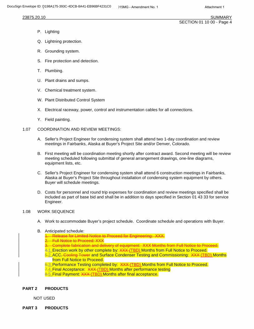
1.08 WORK SEQUENCE
A. Work to accommodate Buyer’s project schedule. Coordinate schedule and operations with Buyer.
B. Anticipated schedule: 1. Release for Limited Notice to Proceed for Engineering: XXX. 2. Full Notice to Proceed: XXX 3. Complete fabrication and delivery of equipment: XXX Months from Full Notice to Proceed. 4.1. Erection work by other complete by: XXX (TBD) Months from Full Notice to Proceed. 5.2. ACC, Cooling Tower and Surface Condenser Testing and Commissioning: XXX (TBD) Months
from Full Notice to Proceed. 6.3. Performance Testing completed by: XXX (TBD) Months from Full Notice to Proceed. 7.4. Final Acceptance: XXX (TBD) Months after performance testing 8.5. Final Payment: XXX (TBD) Months after final acceptance.
PART 2 PRODUCTS
NOT USED
PART 3 PRODUCTS
University of Alaska Fairbanks RFP No. 15P0015MG - Amendment No. 1 Attachment 1DocuSign Envelope ID: D198A175-393C-4DCB-8A41-EB96BF4231C0

23875.20.10 SUMMARY SECTION 01 10 00 - Page 5
NOT USED END OF SECTION
University of Alaska Fairbanks RFP No. 15P0015MG - Amendment No. 1 Attachment 1DocuSign Envelope ID: D198A175-393C-4DCB-8A41-EB96BF4231C0
23875.20.10 SUBMITTAL SCHEDULE SECTION 01 32 19 - Page 1
PART 1 GENERAL
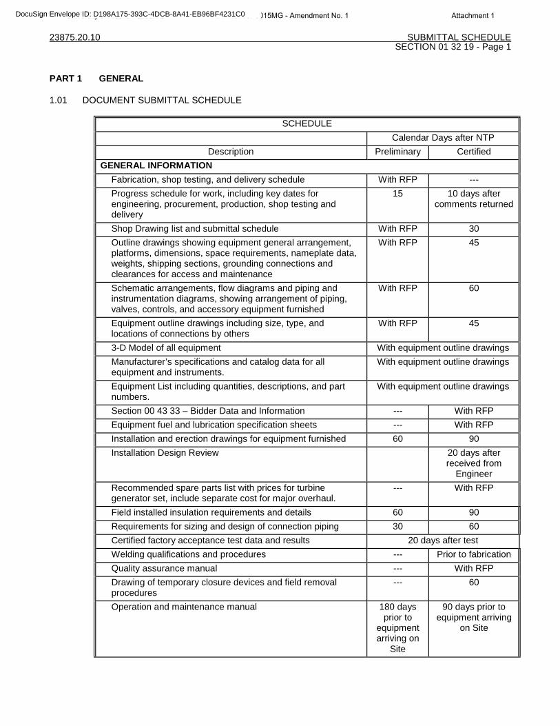
1.01 DOCUMENT SUBMITTAL SCHEDULE
SCHEDULE Calendar Days after NTP
Description Preliminary Certified GENERAL INFORMATION
Fabrication, shop testing, and delivery schedule With RFP --- Progress schedule for work, including key dates for engineering, procurement, production, shop testing and delivery
15 10 days after comments returned
Shop Drawing list and submittal schedule With RFP 30 Outline drawings showing equipment general arrangement, platforms, dimensions, space requirements, nameplate data, weights, shipping sections, grounding connections and clearances for access and maintenance
With RFP 45
Schematic arrangements, flow diagrams and piping and instrumentation diagrams, showing arrangement of piping, valves, controls, and accessory equipment furnished
With RFP 60
Equipment outline drawings including size, type, and locations of connections by others
With RFP 45
3-D Model of all equipment With equipment outline drawings Manufacturer’s specifications and catalog data for all equipment and instruments.
With equipment outline drawings
Equipment List including quantities, descriptions, and part numbers.
With equipment outline drawings
Section 00 43 33 – Bidder Data and Information --- With RFP Equipment fuel and lubrication specification sheets --- With RFP Installation and erection drawings for equipment furnished 60 90 Installation Design Review 20 days after
received from Engineer
Recommended spare parts list with prices for turbine generator set, include separate cost for major overhaul.
--- With RFP
Field installed insulation requirements and details 60 90 Requirements for sizing and design of connection piping 30 60 Certified factory acceptance test data and results 20 days after test Welding qualifications and procedures --- Prior to fabrication Quality assurance manual --- With RFP Drawing of temporary closure devices and field removal procedures
--- 60
Operation and maintenance manual 180 days prior to
equipment arriving on
Site
90 days prior to equipment arriving
on Site
University of Alaska Fairbanks RFP No. 15P0015MG - Amendment No. 1 Attachment 1DocuSign Envelope ID: D198A175-393C-4DCB-8A41-EB96BF4231C0
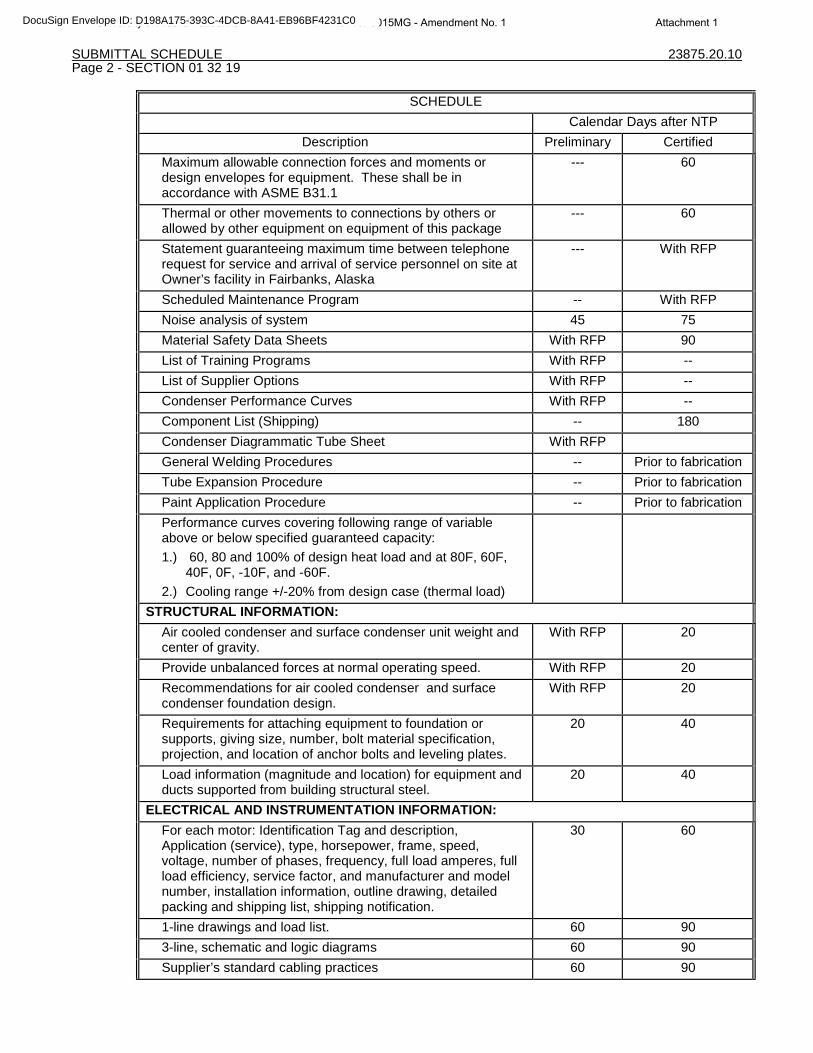
SUBMITTAL SCHEDULE 23875.20.10 Page 2 - SECTION 01 32 19
SCHEDULE Calendar Days after NTP
Description Preliminary Certified Maximum allowable connection forces and moments or design envelopes for equipment. These shall be in accordance with ASME B31.1
--- 60
Thermal or other movements to connections by others or allowed by other equipment on equipment of this package
--- 60
Statement guaranteeing maximum time between telephone request for service and arrival of service personnel on site at Owner’s facility in Fairbanks, Alaska
--- With RFP
Scheduled Maintenance Program -- With RFP Noise analysis of system 45 75 Material Safety Data Sheets With RFP 90 List of Training Programs With RFP -- List of Supplier Options With RFP -- Condenser Performance Curves With RFP -- Component List (Shipping) -- 180 Condenser Diagrammatic Tube Sheet With RFP General Welding Procedures -- Prior to fabrication Tube Expansion Procedure -- Prior to fabrication Paint Application Procedure -- Prior to fabrication Performance curves covering following range of variable above or below specified guaranteed capacity: 1.) 60, 80 and 100% of design heat load and at 80F, 60F,
40F, 0F, -10F, and -60F. 2.) Cooling range +/-20% from design case (thermal load)
STRUCTURAL INFORMATION: Air cooled condenser and surface condenser unit weight and center of gravity.
With RFP 20
Provide unbalanced forces at normal operating speed. With RFP 20 Recommendations for air cooled condenser and surface condenser foundation design.
With RFP 20
Requirements for attaching equipment to foundation or supports, giving size, number, bolt material specification, projection, and location of anchor bolts and leveling plates.
20 40
Load information (magnitude and location) for equipment and ducts supported from building structural steel.
20 40
ELECTRICAL AND INSTRUMENTATION INFORMATION: For each motor: Identification Tag and description, Application (service), type, horsepower, frame, speed, voltage, number of phases, frequency, full load amperes, full load efficiency, service factor, and manufacturer and model number, installation information, outline drawing, detailed packing and shipping list, shipping notification.
30 60
1-line drawings and load list. 60 90 3-line, schematic and logic diagrams 60 90 Supplier’s standard cabling practices 60 90
University of Alaska Fairbanks RFP No. 15P0015MG - Amendment No. 1 Attachment 1DocuSign Envelope ID: D198A175-393C-4DCB-8A41-EB96BF4231C0
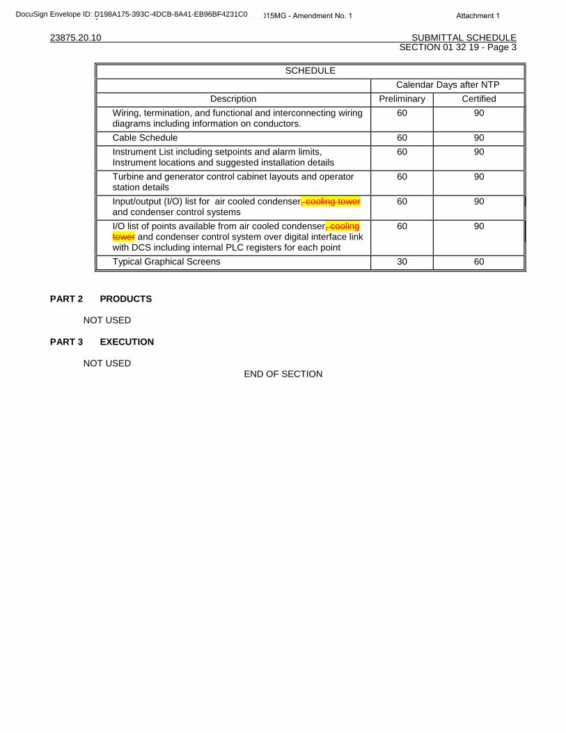
23875.20.10 SUBMITTAL SCHEDULE SECTION 01 32 19 - Page 3
SCHEDULE Calendar Days after NTP
Description Preliminary Certified Wiring, termination, and functional and interconnecting wiring diagrams including information on conductors.
60 90
Cable Schedule 60 90 Instrument List including setpoints and alarm limits, Instrument locations and suggested installation details
60 90
Turbine and generator control cabinet layouts and operator station details
60 90
Input/output (I/O) list for air cooled condenser, cooling tower and condenser control systems
60 90
I/O list of points available from air cooled condenser, cooling tower and condenser control system over digital interface link with DCS including internal PLC registers for each point
60 90
Typical Graphical Screens 30 60
PART 2 PRODUCTS
NOT USED
PART 3 EXECUTION
NOT USED END OF SECTION
University of Alaska Fairbanks RFP No. 15P0015MG - Amendment No. 1 Attachment 1DocuSign Envelope ID: D198A175-393C-4DCB-8A41-EB96BF4231C0
23875.20.10 CONDENSING SYSTEM PERFORMANCE REQUIREMENTS dv126 SECTION 01 86 36 - Page 1
PART 1 GENERAL
1.01 PURPOSE
A. NOTE TO BIDDERS: With the exception of condensing system operational, performance, and reliability requirements, this section should be considered preliminary. Final test procedures will be negotiated after notice of intent to award.
B. The requirements presented in this section shall establish the basis of design and required thermal and operational performance for all equipment provided under this Contract while being operated as a single complete system. Unless otherwise noted in the individual equipment sections, the Seller shall determine the basis of design and required performance of individual pieces of equipment such that the requirements of this section are met during normal operation.
C. Seller shall provide a detailed write-up explaining the operation of the ACC for freeze protection down to the extreme temperature listed in Section 00 43 33 that encompasses the load ranges provided in Paragraph 1.03 A.
D. All operating conditions and thermal performance guarantees are contained in section 00 43 33 – Proposed Products Form. All point value guarantees shall be based on steady load conditions.
E. Conditions of system inputs provided by the Buyer are located in Paragraph 1.04 of this Section. The information provided shall form the basis from which the Seller shall develop the proposed guarantees.
1.02 BASIS OF DESIGN AND PERFORMANCE
A. Design condensing system, including ACC, surface condenser and associated equipment included in this Contract to operate at the guaranteed operating. V values for the guaranteed operating conditions can be found in the Guarantees Section 00 43 33.
B. The condensing system performance guarantees identified in Section 00 43 33 shall be based upon the use of circulating water quality and steam turbine exhaust conditions as identified in this Section, as well as Sections 00 43 33, 48 11 16, and 48 12 17.
C. The equipment shall be capable of operating at any point over the entire load range of the steam turbine and under any ambient conditions.
1.03 OPERATIONAL REQUIREMENTS
A. Operational Range: 10% to 100% of maximum turbine exhaust energy as defined below 1. Maximum Turbine Exhaust Energy: As defined in the Guarantees included in Section 00 43 33. 2. Minimum Continuous Load: 10% of maximum turbine exhaust energy.
B. Meet the following operational requirements over the entire operational range of the steam turbine. 1. Design ACC to maintain turbine exhaust pressure of 10 inchesHg at an ambient temperature of
93°F without the use of the surface condenser. 2. Design ACC to maintain turbine exhaust pressure of 4 inchesHg at an ambient temperature of
40°F without the use of the surface condenser. 3. Design condensing systemACC to maintain turbine exhaust pressure no lower than 2 inchesHg
under any ambient conditions between 40°F and the and the extreme ambient low temperature. 4. The ACC must be capable of continuous operation without internal or external ice buildup
(freezing) by incorporation of various design features such as fan speed variation, sectionalizing (steam isolation valves), isolation from the ambient environment (louvers), and air recirculation.
5. The control logic should be designed to maintain the backpressure by optimizing the fan speed for the ambient conditions and the steam turbine exhaust energy. The control logic shall also
Rev. 0
University of Alaska Fairbanks RFP No. 15P0015MG - Amendment No. 1 Attachment 1DocuSign Envelope ID: D198A175-393C-4DCB-8A41-EB96BF4231C0
23875.20.10 CONDENSING SYSTEM PERFORMANCE REQUIREMENTS dv126 SECTION 01 86 36 - Page 2
automatically protect the system from freezing by varying fan speed, isolating cells, or closing louvers.
1.04 BASIS OF PERFORMANCE GUARANTEES
A. TURBINBE EXHAUST ENERGY 1. As defined in Section 00 43 33.
B. INSTRUMENT AIR 1. The Buyer shall supply adequate instrument air at the following conditions:
a. Supply Pressure: 80-125 psig b. Dew Point: -40.0 °F c. Compressor Type: As required by Seller
1.05 TUNING PERIOD
A. The Seller shall be afforded 30 calendar days to allow for condensing system performance adjustments (tuning) prior to the start of testing.
B. The tuning period may be extended upon request of the Seller and at the discretion of the Buyer.
C. The tuning period shall end no later than 21 calendar days prior to an emissions testing deadline mandated by the Air Permit or any applicable state or federal statutes.
D. The tuning period will be used to check equipment operation and functionality and make any modifications necessary prior to guarantee testing.
1.06 CONDENSING SYSTEM DEMONSTRATION
A. Demonstration will occur during the start-up and commissioning period of the project.
B. Seller shall demonstrate that the equipment provided can meet the Operational Requirements set forth in Paragraph 1.03 of this Section.
C. Seller shall demonstrate that the equipment provided can operate during automatic transitions between ACC only and operation of the entire condensing system/freeze protection modes.
D. Seller shall demonstrate the opening and closing of the freeze protection devices.
E. Seller shall demonstrate that the cooling tower can be placed in and out of service without bringing down the steam turbine.
1.07 PERFORMANCE TESTS
A. Performance testing will consist of: 1. Steam generator performance test 2. Condensing system pressure test 3. Auxiliary power consumption test
B. General Requirements for all performance testing 1. Plant instrumentation will be utilized to the greatest extent possible while still maintaining an
acceptable test uncertainty or tolerance. 2. The Buyer and Seller shall agree to a calibration procedure prior to testing. 3. All performance tests shall be executed by Buyer or a buyer supplied independent third party
(experienced in such work and mutually acceptable to Buyer and Seller). 4. Buyer will notify Seller in writing at least two (2) weeks prior to the scheduled performance test
date. It shall be Seller's responsibility to furnish a test observer on the scheduled date. 5. If any individual performance test identified in 1.07.A requires a retest, it may be run separately.
Rev. 0
University of Alaska Fairbanks RFP No. 15P0015MG - Amendment No. 1 Attachment 1DocuSign Envelope ID: D198A175-393C-4DCB-8A41-EB96BF4231C0
23875.20.10 CONDENSING SYSTEM PERFORMANCE REQUIREMENTS dv126 SECTION 01 86 36 - Page 3
6. The Seller's representative shall act in an advisory capacity and shall have access to all pertinent test records at all times. Any performance test(s) shall be conducted in a manner to satisfy the Seller that the specified performance conditions are being maintained.
7. The equipment supplied by Seller shall be operated and maintained according to Seller's guidelines, good engineering and operating principles and Seller's Maintenance and Operating manual, both prior to and during the performance testing. The Seller shall not be responsible for the deterioration or failure of any equipment resulting from improper maintenance and operation or the failure to observe applicable O&M instructions and written recommendations of the Seller and its subvendors.
C. Initial condensing system performance tests will be run concurrently with performance testing of other major equipment. Availability test may not be run concurrently with performance tests.
D. The performance guarantees are subject to the following provisions: 1. All replacement parts shall be of Seller's manufacture or supply, unless in Seller's judgment
parts supplied by others are of equal or superior quality.
E. Buyer will provide Seller with copies of the final test report, including all raw data in electronic format, within two (2) months of the conclusion of the performance testing.
F. The equipment shall be started-up in presence of a Seller Service Representative. Immediately prior to testing, the equipment shall be operated at a constant rating for a period that is sufficient to demonstrate steady state operation, based upon steam turbine exhaust output. Steady state conditions shall be maintained during the test period.
G. The duration of the test period shall be the minimum required for obtaining representative data but shall not be less than 4 hours.
H. Buyer will utilize the plant historian to record pertinent data collected by the plant DCS. Buyer or third party testing firm will provide and maintain any temporary instrumentation and data logging equipment necessary to obtain additional test data. Buyer will also maintain equipment maintenance logs necessary to monitor operation, from the initial equipment start-up date through the final performance-testing period.
I. All process streams shall be sampled or measured simultaneously.
J. Test tolerance, unless agreed to by all parties due to deviation from ASME PTC test methods, will not be applied to corrected test results prior to comparison to guaranteed values.
K. The procedures described in ASME PTC 12.2, PTC 24 and PTC 30.1 may be modified by mutual agreement of all parties to minimize complexity and cost while maintaining an acceptable test certainty. Should the parties be unable to agree on modifications of the performance test codes, the test shall be conducted in accordance with the test codes with the exception that existing plant instrumentation will be utilized to every extent possible.
L. Auxiliary Power Consumption Test: 1. The auxiliary power consumption will be measured during quantity of four one hour long
performance test periods. Auxiliary power will be measured by summing the power consumption of the equipment listed below using either station and/or portable measurement equipment of reasonable accuracy that has been calibrated within the last year.
2. The auxiliary power consumption shall be recorded for the following equipment: a. Air Cooled Condenser Fans b. Vacuum Pumps c. Any other equipment supplied by Seller that is rated at 5 HP or larger and is in continuous use during normal condensing system operation. Where power consumption instrumentation is not provided as a part of the plant design, the Buyer shall furnish temporary instrumentation to collect the necessary data.
3. The power consumption is to be determined at the motor inlet, or other affected device leads.
Rev. 0
University of Alaska Fairbanks RFP No. 15P0015MG - Amendment No. 1 Attachment 1DocuSign Envelope ID: D198A175-393C-4DCB-8A41-EB96BF4231C0
23875.20.10 CONDENSING SYSTEM PERFORMANCE REQUIREMENTS dv126 SECTION 01 86 36 - Page 4
4. Applicable ASME PTCs shall be used as general guidelines to develop the detailed test procedures.
M. Steam Consumption Test: 1. The auxiliary steam consumption will be measured during quantity of four fifteen minute long
performance test periods. Steam consumption will be measured in accordance with ASME PTC 24.
2. The steam consumption shall be recorded for the following equipment: a. Steam Jet Air Ejector (SJAE) (Holding)
3. ASME PTC 24 shall be used as a general guideline to develop the detailed test procedure.
N. Performance tests and performance calculations shall be made in accordance with the codes and procedures identified in this section or other mutually agreed upon methods in effect as of the original date of the proposal submittal, and the measure of performance shall be the results of such tests. The guaranteed values as stated in Section 00 43 33 are contingent upon measurement in accordance with the following test procedures: 1. Condensing System
a. ASME PTC 12.2 2010 (Steam Surface Condenser) b. ASME PTC 30.1 2007 (Air-Cooled Steam Condensers) c. ASME PTC 24 (Ejectors)a d.
2. Steam Properties a. "Thermodynamic Properties of Steam" per the 1997 ASME Steam Tables
O. Test Corrections 1. Test corrections will be conducted as specified by the applicable PTC
1.08 ADDITIONAL CONSIDERATIONS
A. Should the condensing system performance be limited by equipment outside of the Sellers scope of supply such that the condensing system is not able to reach the guaranteed conditions, the Buyer, at their option, may choose one of the following: 1. Waive any further testing and accept the condensing system performance as is 2. Postpone any further testing until the underperforming equipment can be repaired. Subsequent
condensing system performance testing will be at the Buyers expense and shall be limited to a single retest. The guarantees shall be deemed to be met should the condensing system fail to achieve the guaranteed conditions due to limitations caused by the Buyers equipment upon retest.
PART 2 PRODUCTS NOT USED
PART 3 EXECUTION NOT USED
END OF SECTION 1) R. Hernandez 2) J. Solan
Rev. 0
University of Alaska Fairbanks RFP No. 15P0015MG - Amendment No. 1 Attachment 1DocuSign Envelope ID: D198A175-393C-4DCB-8A41-EB96BF4231C0
23875.20.10 SURFACE CONDENSER SECTION 48 11 16 - Page 1
PART 1 GENERAL
1.01 SECTION INCLUDES
A. Design, furnish, and deliver 1 surface condenser, accessories and auxiliary equipment, instruments, and safety devices for a coal fired combined heat and power plant consisting of two circulating fluidized bed coal boilers, one Shin Nippon C8.5-R13-ERX, single case, axial exhaust, dual extraction, condensing steam turbine generator, in conjunction with SELLER provided ACC and condenser.
1.02 WORK BY OTHERS
A. Labor, superintendence, materials, and equipment necessary for unloading, erecting, and commissioning condenser.
B. Foundation design including anchor bolt supply.
C. Piping external to condenser.
1.03 QUALITY ASSURANCE
A. Manufacturer's qualifications: 1. Proposed condenser shall be a regularly catalogued product of manufacturer. 2. Manufacturer has prime responsibility for vendor surveillance and evaluating and monitoring
implementation of quality assurance program of subvendors. 3. Owner reserves right to require revision to manufacturer’s quality assurance program if deemed
ineffective or inadequate in providing acceptable quality control.
1.04 SYSTEM DESCRIPTION
A. Design requirements: 1. Design and construction of equipment shall conform to HEI Standards for Steam Surface Condensers. 2. The required performance for the parallel condensing system is specified in the Data Sheets in
Section 00 43 33.
B. Arrangement: 1. Steam turbine exhaust arrangement: Axial, however the ACC duct will connect to the turbine exhaust
and a duct tee will direct the exhaust to the condenser. 2. Single-pressure. 3. Number of shells: 1. 4. Number of tube passes: 2. 5. Water box configuration: Divided to allow operation of one half of condenser while other half is out of
service for cleaning. 6. Storage type: Hot well.
C. Limiting dimensions (exact dimensions to suit design) are provide in Exhibit A – General Arrangement Drawings:
D. Turbine-generator characteristics: 1. Nominal generator load, MW: 22.16. 2. Turbine throttle steam pressure, psia: 650. 3. Turbine throttle steam temperature, ºF: 750.
PART 2 PRODUCTS
2.01 FABRICATION
A. Shell:
University of Alaska Fairbanks RFP No. 15P0015MG - Amendment No. 1 Attachment 1DocuSign Envelope ID: D198A175-393C-4DCB-8A41-EB96BF4231C0
SURFACE CONDENSER 23875.20.10 SECTION 48 11 16 - Page 2
1. Design pressure: full vacuum to 15 psig. 2. Steel: ASTM A516 Grade 70. 3. Corrosion allowance: 1/16” (2 mm). 4. Design adequately for conditions under which unit shall operate and shall remain tight under any
operating vacuum. 5. Design for differential expansion between shell and tubes without leakage of circulating water into
steam space.
B. Neck: 1. Arrangement shall suit turbine, turbine foundation, and ACC duct. 2. Expansion joint:
a. Type: One-piece, corrugated element, with internal sleeve. b. Design: Not less than 2 corrugations and design to limit compression forces on associated equipment as required by Sellers design. c. Materials: End pieces connecting to turbine and condenser shell, carbon steel; all other parts, stainless steel.
3. Access: a. Inspection doors: Hinged, not less than 24” (600 mm) diameter.
C. Water boxes: 1. Design pressure, psig: 60. 2. Hydrostatic test pressure, shall be 30 percent higher than design pressure. 3. Steel: ASTM A516 Grade 70. 4. Corrosion allowance: 1/16” (2 mm). 5. Shell attachment: Bolted and gasketed. 6. Inspection doors:
a. Provide 2 per water box to allow inspection of tube ends. b. Type: Hinged, not less than 24” (600 mm) diameter.
7. Provide lifting lugs on each water box. 8. Provide threaded holes and jack bolts for releasing water box inspection doors. 9. Provide internal brackets to support temporary scaffold. Brackets shall be separated by 4’ (1.2 m)
intervals of height. 10. Shop coat water boxes with manufacturer’s standard heavy-duty lining suitable for circulating water
chemistry specified herein. 11. Size for complete waterside draining in 15 minutes. 12. Provide cathodic protection anodes. Quantity and size shall be determined by Contractor.
D. Tube support plates 1. Material: ASTM 304. 2. Corrosion allowance: 1/16” (2 mm). 3. Secure to shell in accordance with manufacturer's standard procedure. 4. Construct tube holes in accordance with manufacturer's standard procedure. 5. Tube support spacing shall comply with method outlined in HEI Standard for Steam Surface
Condensers.
E. Tube sheets: 1. Material: ASTM 304. 2. Corrosion allowance: 1/16” (2 mm). 3. Weld to shell independently of bolts used for connecting shell to water boxes, so water boxes can be
removed without disturbing joint between tube sheet and shell. 4. Tubesheet and tube support plate holes shall be drilled in accordance with the tolerances established
in the HEI "Condenser Construction Standards." 5. Provide means for detecting circulating water leakage into steam space at each tube sheet. 6. Design to withstand concurrent loads imposed by steam space water box pressure, water box nozzle
reactions, water box dead weight, and transient water surge pressure.
F. Tubes: 1. The tube/tube bundle shall be designed to withstand all stresses (mechanical, thermal, operational,
etc.) during startup, shutdown, and normal operation of the condenser.
University of Alaska Fairbanks RFP No. 15P0015MG - Amendment No. 1 Attachment 1DocuSign Envelope ID: D198A175-393C-4DCB-8A41-EB96BF4231C0
23875.20.10 SURFACE CONDENSER SECTION 48 11 16 - Page 3
2. The tubes shall be arranged to be self-draining.. 3. Tubes shall be rolled into the tubesheets 4. The tubes shall be seamless or welded and shall be manufactured from the alloys specified and
according to the ASTM designations.
G. Hot well: 1. Hotwell shall contain condensate equivalent to 3 minutes of design condensate flow between normal
water level and Low-Low (pump trip) water level. Design flow shall be the combined flow of the ACC and condenser.
2. Design with adequate space between water surface and bottom of tube bundle to permit steam flow under tubes for condensate reheating and deaerating.
3. Provide baffles to prevent surging of hot well level and dead zones. Provide cutouts where required to ensure complete drainage.
4. Drain connections shall permit drainage of hot well compartment and sumps in 30 minutes or less. 5. Design for minimum entrance losses of condensate into condensate pump suction piping. 6. Provide 3” (75 mm) high dirt dam and screens at inlet to each outlet sump inlets to retain solids.
a. Size screens to protect condensate pumps. b. Screen opening shall not exceed 1-1/2” (38 mm).
7. Provide anti-vortex vanes at each hot well sump.
H. Supports: 1. Weld to shell at load points. 2. Arrange for solid, bolted mounting. Bolting through bottom of hot well not acceptable.
I. Connections and openings: 1. Provide connections as required by installation including, but not limited to, Terminal Point List
included in Section 01 18 00. 2. Arrange connections to suit specific service and be accessible; subject to Buyer’s review. Location of
miscellaneous connections will be provided by Buyer upon receipt of preliminary condenser arrangement drawing.
3. Provide water and flashing drain inlet connections with stainless steel baffles to protect against direct impingement on condenser tubes.
4. As a minimum, provide internal provisions specified on Terminal Point List. Review connection conditions and provide additional provisions as required.
5. Provide reinforcement pad for connections where indicated in Condenser Connection List.
J. Locate gage, control and alarm device connections so true conditions are indicated, free from velocity, ramming or eddy effects.
2.02 SHOP ASSEMBLY
A. Shop-assemble, to the greatest extent possible, to determine components can be fitted and aligned properly on final assembly. Match-mark to assure proper field alignment.
B. Nozzles, sleeves, thermal sleeves, and baffles shall be shop-welded to condenser shell except where not practical due to packing and shipping considerations. Perforated distribution pipe may be shipped loose for field welding.
C. Box or otherwise suitably prepare parts for shipment to prevent damage in handling and transit. All equipment shall be packaged for shipment via oceangoing vessel.
D. Piping and other openings shall be plugged or capped to prevent entrance of foreign material.
E. Exposed surfaces shall be thoroughly cleaned and external surfaces painted with one coat of shop primer before leaving factory except that machined surfaces shall be thoroughly coated with water soluble rust preventative.
PART 3 EXECUTION
University of Alaska Fairbanks RFP No. 15P0015MG - Amendment No. 1 Attachment 1DocuSign Envelope ID: D198A175-393C-4DCB-8A41-EB96BF4231C0
SURFACE CONDENSER 23875.20.10 SECTION 48 11 16 - Page 4 3.01 MANUFACTURER’S FIELD SERVICES
A. Provide services of field service engineer in accordance with Section 01 43 33.
3.02 NONDESTRUCTIVE EXAMINATIONS (NDE)
A. Perform visual examination before other NDE. Visual examination shall be performed by personnel certified to AWS QC1 requirements.
B. NDE methods, acceptance criteria, and additional general requirements shall be in accordance with applicable fabrication code and this specification.
C. NDE shall be by personnel qualified to Level II or Level III requirements of NDT SNT-TC-1A
D. Radiographic examinations required shall be performed in accordance with requirements of appropriate fabrication code or this specification and shall comply with acceptance criteria of ANSI B31.1 or as specified herein.
3.03 HYDROSTATIC TESTS
A. Shell: 1. Prior to shipment, subject equipment and vessels to water fill leak test to verify shell integrity. 2. Complete condenser, including exhaust expansion joint, shall be tested at job site at conclusion of
installation. 3. No leakage is acceptable through pressure boundary wall or assembly joints. 4. Cribbing shall not be required to perform hydrostatic leak test.
B. Water box: Test in accordance with HEI Standard for Steam Surface Condensers. END OF SECTION 1) R. Hernandez 2) J. Solan
University of Alaska Fairbanks RFP No. 15P0015MG - Amendment No. 1 Attachment 1DocuSign Envelope ID: D198A175-393C-4DCB-8A41-EB96BF4231C0
23875.20.10 AIR COOLED CONDENDSER SECTION 48 11 17 - Page 1
1.01 SECTION INCLUDES
A. Design, manufacture, furnish, and deliver one (1) field-erected air cooled condenser (ACC) and auxiliary equipment, instruments, and safety devices for parallel operation in conjunction with a heat recovery surface condenser and cooling tower; for use in the UAF Combined Heat and Power Plant as described in Section 01 10 00.
B. The work shall include, but not be limited to: 1. Steam ducting between the steam turbine exhaust flange and the ACC. 2. Two (2) drain pumps for steam ducting to transfer drains to the condenser hotwell.(If required) 3. Finned tube bundles with steam distribution manifolds and condensate collection manifolds, non-
condensable gas removal piping to the hogging and vacuum-holding system, and condensate drain piping and pipe supports to the condenser hotwell.
4. Air moving system including motors, fans, gearboxes, couplings, fan guards, bells, fan rings and necessary vibration monitoring and auxiliary equipment.
5. Variable frequency drives (VFD) specifically designed/chosen to operate main air moving system fans. Acceptable drive manufacturers are identified in Section 01 63 00.
6. Monorails, electric hoist(s), and lifting devices required to remove and maintain air moving system. 7. Vacuum pumps to hold ACC vacuum. 8. Complete steam hogger with silencer, to establish ACC vacuum. 9. Galvanized steel structure to support and anchor the ACC, fan deck and A-frames including
maintenance platforms, access stairways, escape ladder, steam ducting, auxiliary equipment, and supplied piping.
10. Necessary instruments and control devices. 11. High pressure water washing system for exterior of fin tubes. 12. Freeze protection by means of steam sectionalizing valve(s) on manifold(s), upper and lower louvers,
and any other means, as required, for part load operation and start up at extreme ambient low temperatures (see Data Sheet for design outdoor air temperature).
1.02 WORK BY OTHERS
A. Receiving, unloading, inspection for shipping damage, piece count, and temporary storage of Equipment at site.
B. Site grading.
C. Foundations and anchor bolts.
D. Labor, equipment and tools for erection of complete assembly.
E. External electrical connections, motor starters and motor controls.
F. Plant distributed control system, programming, and I/O wiring.
G. Condensate drain piping between Terminal Points of the ACC and condenser. Reference Section 01 18 00 for Terminal Points.
H. Condensate forwarding pumps.
I. Lightning protection, grounding grid, and grounding system.
1.03 PERFORMANCE REQUIREMENTS
A. The design turbine backpressure is as indicated in Section 00 43 33.
B. ACC will be located outdoors and will be foundation supported. Auxiliary equipment, such as vacuum pumps, SJAE, hogger, and water wash skid, will be located indoors. Auxiliary equipment shall be fully drainable.
University of Alaska Fairbanks RFP No. 15P0015MG - Amendment No. 1 Attachment 1DocuSign Envelope ID: D198A175-393C-4DCB-8A41-EB96BF4231C0
AIR COOLED CONDENSER 23875.20.10 SECTION 48 11 17 - Page 2
C. The control logic should be designed to maintain the backpressure by optimizing the fan speed for the ambient conditions and the steam turbine exhaust energy. The control logic shall also automatically protect the system from freezing by varying fan speed, isolating cells, and/or closing louvers.
1.04 QUALITY ASSURANCE
A. The ACC and all accessories shall meet the performance requirements in this Specification and Contract Documents. It shall also comply with all applicable codes, laws, rules, guides and regulations as applicable.
B. Seller's experience: Proposed condenser shall be a regularly catalogued product of air cooled condenser manufacturer.
C. Acceptable experience is further defined as having proven performance with the fin tube and heat exchanger bundle design, and the mechanical and manufacturing design and process.
1.05 DELIVERY, STORAGE AND HANDLING
A. Piping and other openings shall be plugged or capped to prevent entrance of foreign material.
B. Thoroughly coat exposed machined surfaces with rust preventative coating.
C. Equipment shall be properly covered, skidded, and crated to withstand shipping via an oceangoing vessel and the normal shocks and vibration associated with the shipment and handling of large equipment.
1.06 GUARANTEES
A. Reference Section 01 86 37 Condensing System Performance Requirements.
B. Performance testing will be performed prior to commercial operation. Compliance with the above performance guarantees may be determined by tests performed within 12 months after commercial operation has commenced.
PART 2 PRODUCTS
2.01 AIR COOLED CONDENSER
A. Scope of supply 1. Steam ducting between the steam turbine exhaust flange and the ACC, including required expansion
joints, turning vanes, guides, anchors, hangers, other support structures, rupture disc assembly(s), drain pot(s) (if required), , manways, and other connections.
2. Two (2) 100-percent-capacity drain pumps for steam ducting (if required by the presence of a drain pot), including instruments, piping, pipe supports, and valves required to transfer drains to the condenser hotwell.
3. Finned tube bundles with steam distribution manifolds and condensate collection manifolds, condensate drain piping and pipe supports to the condenser hotwell as well as supports by the Buyer.
4. Air moving system including motors, fans, gearboxes, couplings, fan guards, bells, fan rings and necessary vibration monitoring and auxiliary equipment.
5. Monorails, electric hoist(s), and lifting devices required to remove and maintain air moving system. 6. Liquid ring vacuum pump skid for air removal with silencers. Vacuum pump skid will hold vacuum
during operation when the SJAE skid is not in use. 7. Steam Jet Air Ejector (SJAE) skid for air removal. SJAE skid will hold vacuum during operation when
the vacuum pump skid is not in use. 8. Steam jet ejector hogging skid for air removal with silencer. 9. Internal partition walls, access doors, and windwall siding material, including windwall steel support
framing. 10. Galvanized steel structure to support and anchor the ACC, fan deck and A-frames including
maintenance platforms, access stairways, escape ladder, steam ducting, auxiliary equipment, and supplied piping. Perimeter walkways and catwalks between A-frames should also be included.
University of Alaska Fairbanks RFP No. 15P0015MG - Amendment No. 1 Attachment 1DocuSign Envelope ID: D198A175-393C-4DCB-8A41-EB96BF4231C0
23875.20.10 AIR COOLED CONDENDSER SECTION 48 11 17 - Page 3
11. Anchor bolt diameter and material requirements. 12. Fasteners (bolts, nuts, washers, screws, pins, etc.) and gaskets required for assembly of materials
furnished. 13. Interconnecting piping and supports within the ACC footprint. 14. Necessary instruments and control devices, including sensors, transmitters, switches, indicators, flow
elements, thermowells, control valves, and pressure safety devices, as required for condenser control, equipment protection, freeze protection, and operation.
15. Special installation and maintenance accessories and tools, including lifting beams, if required, to install and remove the fin tube bundle.
16. Steam duct, risers, manifolds, tanks, piping and supports to be primer-coated. 17. Commissioning spares. 18. Protective coverings and preparation for shipping. 19. Packing, loading, and transportation. 20. Factory testing. 21. Documentation, procedures, and other information. 22. Temporary blanking plates for each ACC row (street), to leak test the ACC after erection. 23. Field service to support startup, operator and maintenance training, commissioning, and field
performance testing. 24. Complete system logic specification in narrative form for incorporation into plant distributed control
system (DCS). 25. High pressure water washing system for exterior of fin tubes, including rolling spray manifolds, hoses,
valves, piping, fittings, and high-pressure pump. Washing system shall be capable of washing either side of the ACC without the need to move the carriage to the other side.
26. Complete set of spare rupture discs, two vibration switches, and two gearbox oil level pressure switches (for commissioning purposes).
27. Noise attenuation devices, as required. 28. Freeze protection by means of steam sectionalizing valve(s) on manifold(s), louvers, or any other
means, as required, for part load operation and start up in very cold winter conditions. Purchaser shall provide thermo-acoustic insulation and/or heat tracing as may be required.
B. Condenser must be designed to operate continuously, 24 hours a day, seven (7) days a week. The condenser must be designed to operate with an average minimum equivalent capacity of 98 percent, and an average availability of 99 percent (annual).
C. Configuration: Forced draft.
D. Maximum allowable air cooled condenser dimensions: 1. Width: Per site layout drawing included in Appendix A. 2. Length: 250 feet.
2.02 FIN TUBE HEAT EXCHANGER BUNDLES
A. Provide condenser tube bundles consisting of finned tubes and headers arranged to distribute steam, remove air, and to provide sufficient drainage for freeze protection in a manner that meets the performance requirements.
B. Mount tube bundles in an A-frame arrangement to meet plot area requirements.
C. Steam and drain headers shall be of all-welded construction. Gasketed joints and threaded plugs are not acceptable. Design tube bundles to allow thermal expansion of tubes and access to tube joints for maintenance.
D. Fin tubes shall be constructed of carbon steel. Guarantee the proper adhesion of the fins to the tubes.
E. Fin tube shall be protected against atmospheric corrosion. Uncoated tubes are not allowed. The following fin tube technologies are accepted: 1. Aluminum fins brazed on flat elongated aluminum cladded carbon steel tubes.
University of Alaska Fairbanks RFP No. 15P0015MG - Amendment No. 1 Attachment 1DocuSign Envelope ID: D198A175-393C-4DCB-8A41-EB96BF4231C0
AIR COOLED CONDENSER 23875.20.10 SECTION 48 11 17 - Page 4
F. Remove all internal and external mill scale and coatings before welding or brazing. Internally flush and rinse brazed tube bundles to remove residual fluoride residues from the brazing process. Protect internal surfaces for ocean shipping and storing.
G. Fins shall be capable of withstanding, without damage or deformation, a direct water jet spray at a pressure of 3,000 psig at a distance of 12 inches, for cleaning purposes and impact of hail up to 1.25 inches in diameter.
H. Tubes shall be elliptical or oval.
I. Fin pitch shall not exceed 11 fins per inch.
J. Fin tubes shall be of single row design to allow for efficient and easy cleaning. Tubes shall be of a flattened tube section to allow for effective heat transfer and low air pressure drop.
K. Provide rigid tube bundles designed to be self-supporting and to be handled as a complete package. Include provisions for thermal expansion of the tube bundles.
L. Design the supports between tubes to ensure that the finned tubes do not have aerodynamic movement and to transmit their weight to the frame structure. Design the support system to take into account the thermal expansion of the pipes and tubes.
M. Design tubes such that individual tube removal and replacement is possible during operation without compromising structural integrity.
N. Each fin tube bundle must be leak tested prior to shipping. The leak test must be an air pressure test in accordance with manufacturer standards. Test procedures must be submitted for review.
2.03 TUBE CLEANING SYSTEM
A. Furnish Seller’s standard semi-automatic tube cleaning system, including required equipment downstream of Buyer’s potable water system. The cleaning system shall be adequate to clean tubes to the guaranteed performance.
B. Provide tube cleaning system capable, at a minimum, of automatically cleaning one tube bundle at a time.
C. Provide necessary hoses, couplings, dollies, etc., to allow the tube cleaning system to move between rows.
D. Design the tube cleaning system to be permanently mounted or stored under the ACC.
E. Design the tube cleaning system to operate with demineralized water supplied at 40-80 psig.
F. Provide tube cleaning system water holding tank. Tank shall be mounted remote from ACC, indoors.
G. Provide valved drain connections to drain the water wash permanent piping and pump.
2.04 FANS
A. Design fans to operate continuously, free from excess vibration, and with provisions to avoid air recirculation under normal operating conditions and the specified service conditions.
B. Provide axial flow fans designed and constructed to permit ease of inspection and maintenance and free from obstructions. Fan blades shall be fiberglass-reinforced plastic or extruded aluminum. Blades shall be axial flow and aerodynamically designed.
C. Establish clearance between the fan blades and the fan ring in accordance with the fan manufacturer’s requirements.
University of Alaska Fairbanks RFP No. 15P0015MG - Amendment No. 1 Attachment 1DocuSign Envelope ID: D198A175-393C-4DCB-8A41-EB96BF4231C0
23875.20.10 AIR COOLED CONDENDSER SECTION 48 11 17 - Page 5
D. Fans shall have manually adjustable pitch and be attached to a common hub. Fan hubs shall be galvanized or epoxy-coated carbon steel. Statically and dynamically balance fan hubs and static-moment balance fan blades before shipment so that any set of blades will fit any hub without rebalancing. Permanently mark all parts for easy reassembly at the site.
E. To maximize fan performance, supply fan rings with inlet bells made of fiberglass or polypropylene segments. Provide sufficient tip clearance between fan blades and fan ring to avoid any rubbing but to not exceed the fan manufacturer’s recommendation.
F. Provide fan motors located in the air removal modules.
G. Ensure that the natural frequency of the structure is not within 20% (above or below) of the fan blade pass frequency across the entire operating speed range. Verify this before the structure is fabricated.
2.05 MOTORS
A. Refer to Section 26 05 03 Small and Medium 3-Phase Motors for requirements.
2.06 VIBRATION SWITCHES
A. The vibration switch shall be capable of providing dual switch levels, providing Alert and Shutdown signals. Both sensor outputs will be routed to DCS by Others.
2.07 GEARBOXES
A. Provide each fan with a gearbox designed especially for the intended continuous service. Equip each gearbox with heat-traced helical gears and anti-friction bearings for heavy-duty service. Design gearboxes to rotate in either direction and to absorb the resulting thrust. The AGMA service factor shall be 2.0 minimum.
B. Design the gearbox in accordance with Cooling Tower Institute (CTI) Bulletin Standard 111, except that the gears and bearings shall be Class B with a minimum lifetime of 100,000 hours.
C. Equip the gearboxes with a forced-flow lubricating system and, if required to implement manufacturer’s warranty, electric oil pumps.
D. Provide each gearbox with the means to fill, indicate level of, drain, and sample the lubricating oil. Provide easy access from the permanent fan drive platform. If necessary, provide each gearbox with an air vent for filling.
E. If gearbox has pressurized oil delivery system, provide connection, isolation valve, and 4-20ma transmitter for oil pressure. If gear box does not have pressurized oil delivery system, provide oil level switch at low level
F. Equip each gearbox with a magnetic drain plug to collect metallic particles that may be present in the lubricating oil.
G. Provide the input shaft end with flexible-disc or elastomeric couplings. Design the coupling between the gearbox and the electric motor to be capable of withstanding both angular and parallel misalignment.
H. Shrink fits (i.e., using an open-flame torch) are not acceptable for gearbox assembly without Buyer written approval.
I. Do not use a roller or ball bearing to accept any thrust force in addition to radial force without written Buyer permission. If this design is used, provide a remote method of determining gearbox lube oil temperature while operating.
J. Bearings shall have an L-10 life of at least 50,000 hours.
University of Alaska Fairbanks RFP No. 15P0015MG - Amendment No. 1 Attachment 1DocuSign Envelope ID: D198A175-393C-4DCB-8A41-EB96BF4231C0
AIR COOLED CONDENSER 23875.20.10 SECTION 48 11 17 - Page 6
K. Provide smooth mounting surface for standard accelerometer vibration sensor mounting in both X (horizontal) and Y (vertical) planes.
2.08 MAIN STEAM DUCT
A. Design and furnish a steam duct of welded construction from the turbine exhaust connection to the ACC, including the expansion joint at the turbine interface.
B. Slope horizontal sections of the steam duct away from the steam turbine exhaust (drain away from turbine).
C. Provide a low point drain pot to remove condensate from the exhaust duct. A drain pot is not necessary if the branch duct to the surface condenser is configured such that water in the exhaust duct will naturally drain to the surface condenser hotwell.
D. Slope horizontal sections of the steam duct toward the steam duct drain pot at a minimum of ¼-inch per 10-feet.
E. As required, provide reinforcement plates around steam duct penetrations.
F. As necessary, provide reinforcement plates and support plates on the steam duct for attachment of Buyer’s supports for piping and cables routed between the ACC and Buyer’s steam turbine building.
G. Provide butt- or socket-welded connections except where bolted connections are required for maintenance.
H. Provide minimum 24 in. diameter hinged access manways in steam duct and distribution headers for internal inspection. Provide a minimum of two manways (one at each end) in the horizontal run of the steam duct between the steam turbine and the ACC.
2.09 REFLUX WARM-UP SYSTEM (IF REQUIRED)
A. Warm-up system will send plant low pressure steam to the condensate headers to preheat the tube bundles prior to turbine rolloff, cold weather only.
B. Steam will be supplied from the plant low pressure steam header.
2.10 DRAIN POT PUMPS (IF REQUIRED)
A. Mount pumps on a common base.
B. Provide two (2) 100 percent capacity pumps suitable for the service conditions and sized to collect condensate from the low point drain pot during both startup and normal operation. Return condensate to the condenser hotwell.
C. Provide an isolation valve and a startup basket strainer in each pump suction line. Provide a spool or spacer plate to replace the startup strainer during normal system operation. Provide a “non-slam” non-return valve and a manual isolation valve in each pump discharge line. The strainers shall be removable without breaking vacuum.
D. Furnish pumps with casing vents with plugs.
E. Design pumps to operate satisfactorily when delivering varying quantities of fluid up to the maximum pump output. Size pump motors so that the selected pump impeller shall not overload the motor at any point on the pump head capacity curve.
F. Generally size pumps for maximum efficiency at the normal operating point. Provide pumps that remain free from excessive vibration throughout the operating range.
University of Alaska Fairbanks RFP No. 15P0015MG - Amendment No. 1 Attachment 1DocuSign Envelope ID: D198A175-393C-4DCB-8A41-EB96BF4231C0
23875.20.10 AIR COOLED CONDENDSER SECTION 48 11 17 - Page 7
G. Size pumps furnished for each application to accept an impeller at least 1/8 inch larger in diameter than the impeller specified without having to change the pump casing.
H. Design horizontal end suction pumps to allow the impeller to be withdrawn from the motor end without disturbing the piping or motor.
I. Where necessary, fit vent and drain valves at suitable points on the pump casing and pipe to floor drains. Design horizontal split-case pumps to allow the removable half-casing and impeller to be withdrawn without disturbing any of the process piping, valves, or motor.
J. As determined by the application, provide pumps with either packing or mechanical seals. Arrange pumps that have mechanical seals to facilitate removing the seals. Specify shaft flingers to prevent packing gland leakage water from entering the bearing housings.
K. Provide bearings with ample surface area. For pumps larger than 100 Hp, provide journal bearings, split for ease of maintenance. Arrange bearings to facilitate removing the pump impeller for repairs.
L. For ball or roller bearings, fit the inner race directly onto the shaft and locate it by a machined shoulder on the shaft. Securely connect intermediate shaft bearings of vertically suspended pumps to the main pump support tube.
M. For bearings requiring cooling water, provide the necessary pipe work, valves, and strainers. Vertical-shaft freshwater or condensate pump bearings situated below water level shall be lubricated by the water being pumped.
N. Provide guards for couplings and any intermediate shafting.
O. Provide bedplates of ample proportions and stiffness to withstand the loads likely to be experienced in shipment and service.
P. Supply pumps used in vacuum service with water seals.
2.11 PIPING AND VALVES
A. Provide the following: 1. Condensate collection piping within the ACC A-frame envelope, terminating at a single connection
point, as noted in Section 01 18 00 Terminal Points. 2. Air removal piping within the ACC A-frame envelope, terminating at a single connection point, as noted
in Section 01 18 00 Terminal Points. 3. Water wash tubing and piping from the pump to the outlets at the fan deck.
B. Furnish and install piping, valves, and associated supports in accordance with ASME B31.1. Use welded construction for pressure boundaries to minimize potential for air inleakage. Design branch connection details in accordance with manufacturer’s standards and ASME B31.1.
C. All piping material shall be ASTM A-106, Grade B, or ASTM A-53, Grade B, carbon steel with exterior primer coating. For exterior piping, use carbon steel materials suitable for temperatures below -60F; such as ASTM A-333 Gr. B.
D. Equip valves exposed to condenser vacuum with special packing and backseats for vacuum service. Furnish valve stems with lantern ring and leakoff connection (plugged) for future water seal.
E. Where practical, arrange valves for convenient access and operation from grade or platforms. Where this is not possible, provide valves with extension stems or chain operators.
F. Provide high point vents and low point drains. Conform design to the requirements of manufacturer’s standards.
University of Alaska Fairbanks RFP No. 15P0015MG - Amendment No. 1 Attachment 1DocuSign Envelope ID: D198A175-393C-4DCB-8A41-EB96BF4231C0
AIR COOLED CONDENSER 23875.20.10 SECTION 48 11 17 - Page 8
G. All materials used in the construction of pipe supports, guides, restraints, and anchors shall be in accordance with ASME B31.1. Materials shall be compatible with the piping materials.
H. Consider the most severe conditions of coincident pressure, weight, temperature, and any other fluid dynamic events, and any other applicable loadings, in the design of pipe supports. In addition to the above loading conditions, design piping routed outside and above ground for wind and snow loads (as applicable).
I. Design shear lugs so that half of the shear lugs resisting the load support the total load.
J. Design structural and miscellaneous steel in accordance with AISC standards and specifications.
K. Identify any insulation and heat-tracing requirements on the P&ID.
L. Supply piping in random lengths, with field trim, with one fitting welded on one end.
2.12 MAIN CONDENSATE
A. Condensate from the ACC shall be directed to the condenser hotwell.
B. Deaeration of the condensate is not required.
2.13 VACUUM PUMPS
A. The pumps shall be designed for continuous service when operating under all service conditions, flow capacities, and pressures as depicted in section 00 43 33.
B. The pumps shall be sized to hold vacuum on the condenser under all normal operating conditions.
C. Seller shall furnish a 100% capacity vacuum pump. vacuum pump shall be designed for 100% air removal capacity. The pump supplied shall be a positive displacement, non-pulsating, liquid ring, rotary vacuum pump with a seal water heat exchanger and separator.
D. The pump shall be driven by a low-speed motor without the use of speed reducers.
E. All pump connections shall be flanged and shall be located above the base plate. The pump must be complete with a structural steel base plate to accommodate pump, motor, and accessories.
F. The pump shall have a gear type flexible coupling and guard between the pump and motor providing access to bearings and seals without moving either the pump or motor which spare parts are available.
G. Pump components that are subject to wear shall be readily replaceable with minimum disturbance to connection piping, drives, etc.
H. Each pump shall be furnished complete with the necessary valves, controls, wiring, and accessories for automatic operation.
I. The pump controls shall operate on 120 volt AC power.
J. All electrical components shall be housed in NEMA 4 weather-proof and watertight enclosures. Enclosures shall have removable covers to provide easy access to connection points and to facilitate adjustments, inspections, and replacements.
K. Each pump shall be furnished with a plate and frame seal water heat exchanger fabricated in accordance with ASME Section VIII. The heat exchanger shall have a maximum design approach temperature of 2.5°F.
L. The pressure drop across the heat exchanger shall be a maximum of 50% of the total pressure drop across the main condenser.
University of Alaska Fairbanks RFP No. 15P0015MG - Amendment No. 1 Attachment 1DocuSign Envelope ID: D198A175-393C-4DCB-8A41-EB96BF4231C0
23875.20.10 AIR COOLED CONDENDSER SECTION 48 11 17 - Page 9
M. Each pump shall be capable of maintaining its design capacity at all ranges of seal water inlet temperatures for the design heat duty.
N. Standard conditions for determining vacuum pump scfm capacity shall be 14.7 psia at 60°F in accordance with HEI standards.
O. The Vendor shall design and furnish pumps suitable for operation over the entire range of expected condenser operation without cavitation.
P. Pumps with cavitation protection shall have a maximum impeller tip speed of 75 feet/second. The Vendor must provide documented proof that the cavitation protection method installed on the pump serves the intended purpose and will not limit condenser pressure or pump capacity.
Q. Pumps without cavitation protection shall have a maximum pump rotational speed of 1200 rpm with a maximum impeller tip speed of 85 feet/second.
2.14 STEAM JET AIR EJECTOR
A. Provide a 100% capacity two-stage, steam jet holding ejector(s), (hogging skid may be packaged with holding skid, if applicable).
B. Provide a silencer to be installed in Seller-furnished exhaust piping to limit noise, as required.
C. A single 100% capacity inter/after condenser must also be provided, allowing simultaneous operation of both ejector trains. The ejector system must be designed to provide 100% rated ejection capacity throughout the range of operating suction pressures.
D. C. Cooling water supply to the inter/after condenser of the holding ejectors will be condensate forwarded by the condensate pumps. Condenser waterside design pressure must be 500 psig minimum. Maximum waterside pressure drop must be less than 10 psi at 100% condensate flow.
E. Motive steam for the SJAE will be from the plant auxiliary steam system at the temperature and pressure defined in Section 00 43 33.
F. Provide necessary piping, valves, fittings, and instruments for a complete skid assembly.
G. Design and construct the holding ejector in accordance with applicable HEI Standards for Steam Surface Condensers and Air Cooled Condensers.
2.15 STEAM HOGGING EJECTOR
A. Provide a single-stage, steam jet hogging ejector(s) with no after-cooler, that exhausts to atmosphere (hogging skid may be packaged with holding skid, if applicable).
B. Provide a silencer to be installed in Seller-furnished exhaust piping to limit noise, as required.
C. Motive steam for the SJAE will be from the plant auxiliary steam system at the temperature and pressure defined in Section 00 43 33.
D. Provide necessary piping, valves, fittings, and instruments for a complete skid assembly.
E. Mount the hogging ejector and associated components on a steel base and shop-assemble to maximum extent possible.
F. Design and construct the hogging ejector in accordance with applicable HEI Standards for Steam Surface Condensers and Air Cooled Condensers.
G. Provide a motor-operated air inlet isolation valve on the hogging ejector.
University of Alaska Fairbanks RFP No. 15P0015MG - Amendment No. 1 Attachment 1DocuSign Envelope ID: D198A175-393C-4DCB-8A41-EB96BF4231C0
AIR COOLED CONDENSER 23875.20.10 SECTION 48 11 17 - Page 10
H. Capacity must be sufficient to reduce pressure in the entire air cooled condensing system and turbine from atmospheric pressure to 10 inches HgA in less than 30 minutes.
2.16 WINDWALL AND CLADDING
A. Furnish a complete windwall enclosure around the perimeter of the ACC. As a minimum, extend the windwall from the fan platform level upward to the top of the fin tube bundles.
B. Base windwall requirements on design and site related factors (minimum ambient temperature, wind speed, prevailing direction, condensate temperature and warm air recirculation potential).
C. Fabricate the windwall of un-insulated, corrugated, galvanized steel panels with factory-applied paint finish (color shall match sample provided by Buyer) secured by exposed stainless steel fasteners. Provide flashing and sealing materials for fascia, base, corners, and around all wall penetrations and openings. Flashing material and finish shall be same as specified for wall panels.
D. Supply the windwall siding and primed support structure per Seller's standard design. Make all attempts to match standard siding shape and finish used throughout the balance of the plant. Provide windwall girt system in accordance with Seller's standard design and using steel shapes SellerSeller normally supplies.
E. Make structural provisions for attaching girts to the ACC structure to transfer all loads from the siding (cladding) system to the structure. Design each siding (cladding) and girt system member to withstand stresses resulting from combinations of loads producing the maximum stresses in that member as indicated in the governing design code.
2.17 STAIRWAYS, LADDERS, WALKWAYS, AND PLATFORMS
A. Provide hot-dip galvanized steel platforming (open grating or Buyer prior-approved alternate), ladders, stairs, treads, cages, handrails, etc., located to permit ready access to all parts of the ACC, steam duct manways, and auxiliary equipment that may require operator attention during operation and to permit ease of maintenance when the ACC is out of service for repairs.
B. Provide one stair tower, located on the north end of the ACC, including handrails, toe kicks, landings, and other required accessories for a complete stair system. Stairs shall provide access to grade and all platform levels.
C. Supply a single caged ladder central to the opposite side wall (south-side). Ladder shall provide access to the fan platforms from grade.
D. Design the fan platform to provide easy access to and support of the mechanical equipment, equip the platform with handrails, and provide a walkway over the entire length.
E. Provide a walkway around the entire perimeter of the ACC at the fan platform level.
F. Provide walkways to give obstacle-free access to all operating points and manways.
G. Provide catwalks between each row of adjacent A-frame sections of the ACC. Catwalks shall have a minimum unobstructed width of 18 inches and a minimum free overhead space of 7 feet.
H. Both the walkways and stairways shall have a minimum unobstructed width of 36 inches and a free overhead space of at least 7 feet.
I. Equip all stairways, catwalks, walkways, and platforms with kickplates and with handrails that include an intermediate pipe and baseplate.
J. Provide platforms for the steam duct rupture disc and each steam duct manway. As a minimum, platforms shall be 3 ft x 3 ft. Provide permanent access to all platforms, except the steam duct rupture disc and the manways in the steam distribution headers.
University of Alaska Fairbanks RFP No. 15P0015MG - Amendment No. 1 Attachment 1DocuSign Envelope ID: D198A175-393C-4DCB-8A41-EB96BF4231C0
23875.20.10 AIR COOLED CONDENDSER SECTION 48 11 17 - Page 11
K. Provide adequate space for safe placement of and access to a moveable/temporary ladder on each exterior side face of each row of tube bundles for access and inspection and for access to the platform at the steam duct rupture disc and the manways on the steam distribution headers without sectioning valves.
L. Provide moveable/temporary ladder(s) for access to tube bundles, rupture disc platform and the manways in the steam distribution headers without sectioning valves.
2.18 MAINTENANCE TROLLEY BEAMS AND HOIST
A. Furnish monorail beams for each condenser row (street) extending the entire length of the street/row. To facilitate removing fan motor and gearboxes and lowering them to ground level, overhang the beams at one end of the platform or provide removable sections of walkway.
B. Furnish movable trolley and electric hoist of standard manufacturer's design for each monorail beam.
C. Provide festooned cable, supported from the monorail, to allow the hoist/trolley to travel the length of the street/row.
D. Design monorail beams and hoist so that it is not necessary to remove partition walls to allow trolley/hoist movement.
2.19 STRUCTURAL
A. The ACC will be supported from grade.
B. The condenser, accessories, and components must be supported on braced structural steel columns designed and fabricated in accordance with the codes, standards, seismic, wind, and snow load conditions in this Specification.
C. Structural Design Criteria 1. Reference Section 01 83 00 – Structural Performance Requirements for the following design criteria: 2. Seismic 3. Wind loads 4. Snow loads 5. Other design criteria not related to the local environment
2.20 INSTRUMENTATION AND CONTROLS
A. Design control logic for the ACC, steam duct drain pumps, holding vacuum pumps, holding ejector and hogging ejector. This control logic shall be implemented in Buyer’s DCS to operate automatically over all operating, startup, shutdown, load change, and ambient conditions with steam from the steam turbine and in conjunction with the condenser.
B. Design control logic to also allow manual override to accomplish all automatic functions. Ensure that the functional design of Seller’s control systems does not restrict operation or response or cause dangerous conditions.
C. Design pressure, level, and temperature sensors to be serviced or replaced without removing the ACC from service.
D. Provide necessary field-smart transmitters, sensors, switches, etc., to support the ACC, steam duct drain pumps, and vacuum system. Provide thermocouple or RTD temperature sensors as specified.
E. Provide all final control drives, actuators, positioners, etc., to control the equipment furnished.
F. Provide fan vibration alarm and trip switches, each with two (2) double-pole, double-throw (DPDT) contacts.
University of Alaska Fairbanks RFP No. 15P0015MG - Amendment No. 1 Attachment 1DocuSign Envelope ID: D198A175-393C-4DCB-8A41-EB96BF4231C0
AIR COOLED CONDENSER 23875.20.10 SECTION 48 11 17 - Page 12
G. Provide either gearbox oil flow or pressure switch for each fan drive gearbox and/or its associated lube oil reservoir.
H. Provide local level indicator for each fan drive gearbox and/or its associated lube oil reservoir.
I. If drain pot is provided, provide one (1) level transmitter and four (4) level switches for the steam duct drain pot (“high-high,” “high,” “low,” and “low-low”) with two (2) DPDT contacts suitable for 120 VAC. The steam duct drain pumps will be controlled through the Buyer’s DCS. Provide local pump discharge pressure indicator.
J. Provide temperature elements (RTD’s) in each condensate return header between the reflux bundles and condenser bundles. Provide temperature elements (RTD’s) in the non-condensable outlet header from each reflux cell.
K. Provide two (2) ambient temperature elements (RTD’s), installed in a location to prevent heating effects from exposure to the sun.
L. Provide one (1) duplex RTD at the inlet of the steam duct.
M. Provide two (2) pressure transmitters at the entrance to the steam duct: one (1) 0-30 psia and one (1) 0-5 psia for fan control. Make tube runs short and sloped to the steam duct.
N. Provide a set of instrumentation for each vacuum pump skid for proper equipment operation. Air flow meters shall be sensitive enough to measure the full range of expected air in leakage.
O. Design and furnish all equipment suitable for outdoor service.
P. Provide instruments and instrument connections required to monitor and test performance, except steam flow and quality and total power, which will be measured by Buyer.
Q. Provide isolated digital and isolated 4-20 mA analog signal outputs to Buyer's DCS.
R. Except when measuring gas or air temperatures at atmospheric pressure, protect temperature elements by thermowells. Equip temperature test points with thermowells and caps or with plugs and chain.
S. Any thermocouples used shall be ANSI dual-element, ungrounded, spring-loaded, Chromel-Constantan. A local temperature transmitter shall be provided for each thermocouple transmitting a 4-20 mA signal.
T. Any RTDs used shall be dual-element, 100 ohm, platinum, three-wire (R100/RO-1.385), ungrounded. The element shall be spring-loaded, mounted in a thermowell, and connected to a cast iron head assembly. A local temperature transmitter shall be provided for each RTD transmitting a 4-20 mA signal.
U. Provide a wind speed, outside air temperature and direction instrument transmitting a 4-20 mA signal.
2.21 ELECTRICAL
A. Refer to Sections 26 05 03 Small and Medium 3-Phase Motors, 26 05 00 Common Work Results for Electrical Packaged Equipment and 26 29 23 Low Voltage Variable Frequency Drives for additional requirements.
2.22 COLD WEATHER OPERATION/FREEZE PROTECTION
A. Freeze protection shall be designed to protect the unit assuming the worst combination of operating conditions provided in Section 00 43 33 – Bidder Data and information. At a minimum the Seller shall use the minimum continuous steam turbine exhaust flow rate at the extreme minimum ambient temperature.
B. The design shall allow sections of the ACC to be isolated for freeze protection during cold weather and low load operation. Provide motor operated upper and lower louvers and motor operated sectionalizing valves for cold weather operation.
University of Alaska Fairbanks RFP No. 15P0015MG - Amendment No. 1 Attachment 1DocuSign Envelope ID: D198A175-393C-4DCB-8A41-EB96BF4231C0
23875.20.10 AIR COOLED CONDENDSER SECTION 48 11 17 - Page 13
C. The ACC shall be designed to allow safe operation at specified minimum steam flow and concurrent minimum ambient temperature.
D. The tubes, headers, drain pots and piping shall be sized and designed to drain freely and completely to prevent damage due to freezing.
E. Seller shall indicate the need to electric heat trace and insulate instrument control or process lines that may freeze during cold weather.
F. Condensate piping shall be, preferably, self-draining into the condenser hotwell. If low points exist, piping shall be electric heat traced and insulated to prevent freeze up in the event of a winter shutdown. Low point drains shall also be provided. The Buyer shall provide insulation and heat tracing.
G. The ACC shall be designed to prevent uneven distribution of steam and cooling air and excessive sub-cooling of the non-condensable gas so that the evacuation system is not overloaded by steam, and to provide freeze protection in the cold climate.
H. Fin tubes must be designed to accommodate freeze/thaw cycles.
I. Freeze protection features included in Seller’s design must be described in detail in the bid package.
2.23 SOUND LEVELS A. Basis of Design (for inclusion in bid price)
1. The steady state sound level from the ACC shall not exceed 37 dB(A) when measured at 400 ft. in any direction from the ACC in a free-field environment.
B. Alternate Noise Option #1 (provide optional price deduct, if applicable) 1. The steady state sound level from the ACC shall not exceed 42 dB(A) when measured at 400 ft. in
any direction from the ACC in a free-field environment. C. Alternate Noise Option #2 (provide optional price deduct, if applicable)
1. The steady state sound level from the ACC shall not exceed 47 dB(A) when measured at 400 ft. in any direction from the ACC in a free-field environment.
D. Additional sound requirements: 1. Above fan discharge: 77 dB(A). 2. 5'-0" horizontally from tower: 69 dB(A). 1.3. Steam silencer outlets: 85 dB(A) at 3 feet horizontally from silencer .
PART 3 EXECUTION
3.01 GUARDS AND SAFETY DEVICES
A. Exposed rotating parts of machinery, including couplings, drives, or other extensions, shall be properly protected with OSHA-approved guards.
3.02 FIELD TESTS
A. It shall be the responsibility of Buyer to provide testing as necessary to verify compliance with guaranteed performance. Tests shall be in accordance with ASME PTC 30.1.
B. Buyer shall provide, services of independent testing firm to conduct test and certify results of ACC performance.
C. If guaranteed performance is not achieved in performance tests, Seller shall make necessary changes and adjustments to Equipment at no cost to Buyer and notify Buyer when ready for retesting or supplemental testing.
D. Field testing shall confirm summer capacity at design conditions in section 00 43 33.
3.03 DEFECTIVE EQUIPMENT
University of Alaska Fairbanks RFP No. 15P0015MG - Amendment No. 1 Attachment 1DocuSign Envelope ID: D198A175-393C-4DCB-8A41-EB96BF4231C0
AIR COOLED CONDENSER 23875.20.10 SECTION 48 11 17 - Page 14
A. If Equipment fails to conform to requirements of Contract Documents or to operate satisfactorily, correct such defects promptly at no cost to Buyer.
B. Buyer will have the right to operate unsatisfactory Equipment until it is replaced or corrected, without cost for depreciation, use, or wear.
C. Equipment will be removed from operation for examination, adjustment, alteration, or change only at times approved by Buyer.
END OF SECTION
1) R. Hernandez 2) J. Solan
University of Alaska Fairbanks RFP No. 15P0015MG - Amendment No. 1 Attachment 1DocuSign Envelope ID: D198A175-393C-4DCB-8A41-EB96BF4231C0
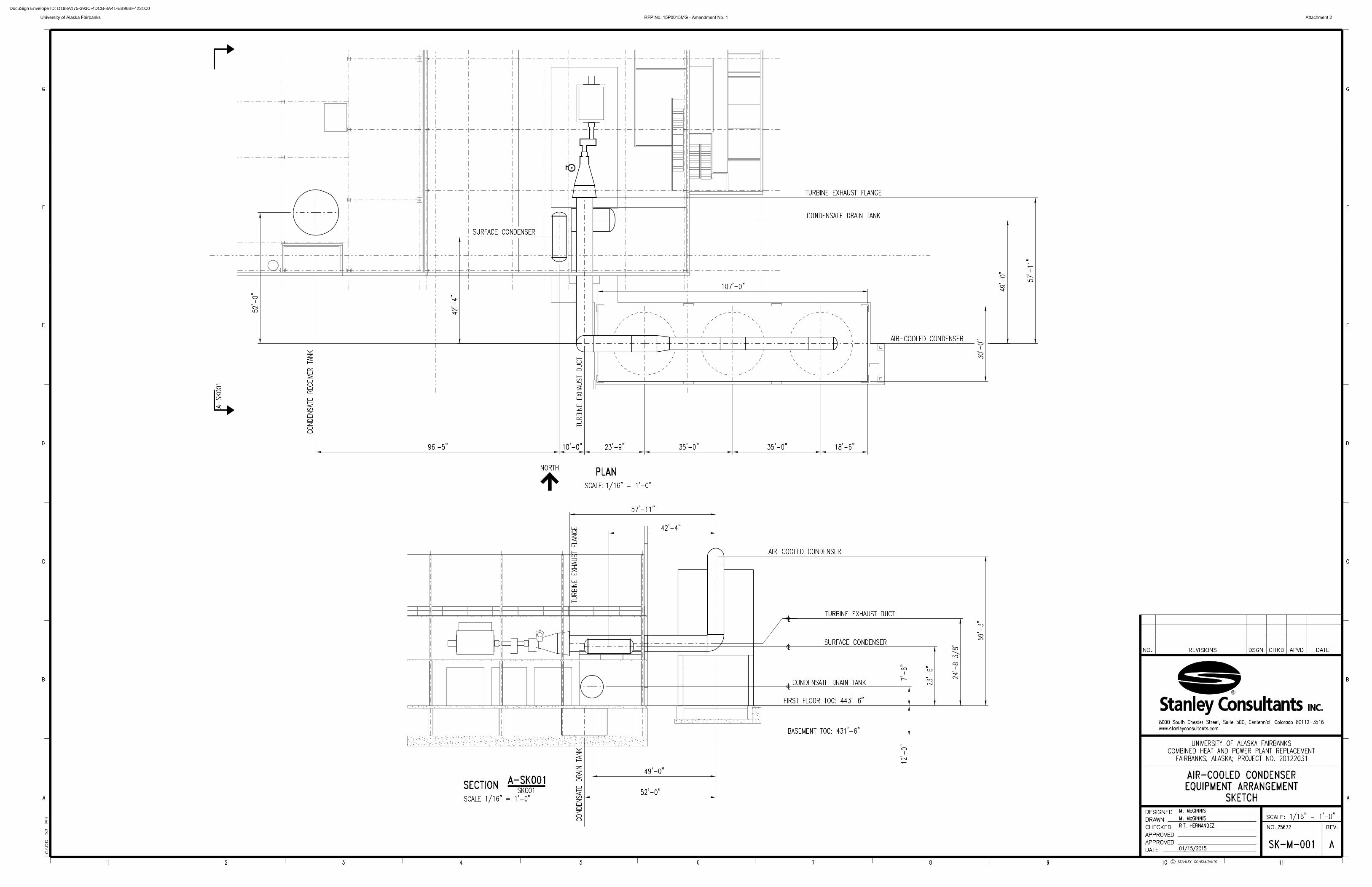
University of Alaska Fairbanks RFP No. 15P0015MG - Amendment No. 1 Attachment 2
DocuSign Envelope ID: D198A175-393C-4DCB-8A41-EB96BF4231C0