allweiler operating and maintenance instructions vm...
TRANSCRIPT

ALLWEILER
1
Operating and Maintenance Instructions VM No.: 670.0010 GB
Edition: 11.99
Ident No.: 550 218
Screw pumps Retain for future
Series SM...AR.. use!
Design D/E 4.2QM
Order no.: Pump ident. no.:
Machine no.: Pump type:
Operating data of pump as per order data sheetDimensions as per order dimension drawing
Contents
1. General
2. Safety
3. Transportation and Intermediate Storage
4. Description
5. Installation/Mounting
6. Start–up/Shutdown
7. Maintenance/Repair
8. Operating Faults, Causesand Remedial Action
9. Associated Documentation
These Operating and MaintenanceInstructions contain information fromthe pump manufacturer. They may needto be supplemented by instructions ofthe operator company for its personnel.These instructions do not take accountof specific information relating to opera-tion and maintenance of the processplant into which the pump is integrated.Such information can only be given bythe persons responsible for construc-tion and planning of the plant (plantmanufacturer).Such specific instructions relating tooperation and maintenance of theprocess plant into which the pump isintegrated have priority over theinstructions of the pump manufac-turer.
Refer to the operating instructions ofthe plant manufacturer!

ALLWEILERSM...AR..D/E4.2QM
2VM 670.0010 GB/11.99 – Ident–Nr. 550 218
1 General
1.1 AbbreviationThe abbreviation of the screw pump is set up accordingto the following schema, and is engraved on the typeplate.
Example:
Series
SM H 40 AR 46 D4.2QM E–W61
Type series
DesignH = Horizontal foot pump
GH = Horizontal foot pump,branches U–turn
E = Cartridge–unit pump forH and GH pumps
F = Flange pump
GF = Flange pump,branches U–turn
S = Plinth pump
GS = Plinth pump,branches U–turn
EF = Cartridge–unit pump forF, GF, S and GS pumps
Size= theoretic delivery in [l/min]
with normal pitch and 1450 1/min
Type of driving spindle
Direction of screw pitchR = right (serial design)L = left
Angle of screw pitch [degrees]
Special design featureD = Rolling bearing pre–mounted,
Mechanical seal uncooled/unheatedE = Rolling bearing pre–mounted, regreasable
Mechanical seal uncooled/unheated
Shaft seal4.2 = 3 teflonized shaft seal rings
Special design featureQM = Quench receiver for lubricant/flushing agent
Casing heatingE = Heating bars, electricP = Heating cartridge for steam or heat carrierX = Heating shell for steam or heat carrierY = Double shell for steam or heat carrier
Material code
1.2 Application and range of utilizationThe inside–bearing screw pumps of type seriesSM...AR.. are three–screw, rotary positive displace-ment pumps for lubricating liquids. The liquids must notcontain any abrasive particles nor chemically attack thepump materials.Due to a modular system, the pumps may be designedas cartridge–unit pumps, horizontal foot–mountedpumps, flange–mounted pumps as well as verticalplinth–mounted pumps.
1.3 Performance dataThe exact performance data applicable to the pumpcan be taken from the order data sheet and/oracceptance test report, and are engraved on the nameplate.The pressure data indicated there apply only toapproximated static pressure load. In the case ofdynamic alternating pressure load, consult themanufacturer.
1.4 WarrantyOur warranty for shortcomings in the supply is laiddown in our delivery conditions. No liability will beundertaken for damages caused by non–compliancewith the operating instructions and service conditions.If at any later date the operating conditions change (e.g.different fluid conveyed, speed, viscosity, temperatureor supply conditions), it must be checked by us fromcase to case and confirmed, if necessary, that the pumpis suited for those purposes. Where no specialagreements were made, pumps supplied by us may,during the warranty period, only be opened or varied byus or our authorized contract service workshops;otherwise our liability for any defects will cease.
1.5 TestingPrior to leaving our factory, all pumps are subjected to athorough test run and performance test on the teststand. Only properly operating pumps, achieving theperformance assured by us, leave the factory.Thus, compliance with the following operatinginstructions ensures fault–free operation and fulldelivery.
1.6 AvailabilityAs a matter of principle, we recommend stockingreplacement pumps and withdrawable units (hydraulicaction system) where the supplied pumps are adecisive factor in maintaining a production or deliveryprocess. In this way downtimes can be avoided, orreduced to a minimum.

ALLWEILERSM...AR..D/E4.2QM
3VM 670.0010 GB/11.99 – Ident–Nr. 550 218
2 Safety
These operating instructions contain basic safetyinstructions for installation, operation andmaintenance. It is therefore essential that they are readby fitters and all specialist staff and customer personnelprior to installation and start–up. They must always bekept at hand at the place of installation.
The special safety instructions contained in the otherchapters must be observed in addition to the generalsafety instructions in this chapter.
2.1 Identification of safety instructions in theoperating manualThe safety instructions contained in these operatinginstructions which represent a danger to personnel ifnot complied with are specially marked by the generaldanger symbol:
Warning symbolas per DIN 4844–W9
Warning of danger from electric voltage is indicated asfollows:
Warning symbolas per DIN 4844–W8.
Instructions which are essential to avoid endangeringthe machine and its operation are marked by the word
ATTENTION
Instructions affixed directly to the machine such as
� Directional markers
� Signs for fluid connections
must always be observed and maintained in fullylegible condition at all times.
2.2 Personnel qualification and trainingThe operating, maintenance, inspection and mountingpersonnel must be appropriately qualified for the dutiesassigned to them. The scope of their responsibilities,competency and supervisory duties must be closelycontrolled by the customer. If the personnel do not havethe required knowledge, they must be trained andinstructed. If required, this may be provided by themanufacturer/supplier on behalf of the customer. Thecustomer must additionally ensure that personnel fullyunderstand the content of the operating instructions.
2.3 Dangers in the event of non–compliance withsafety instructionsFailure to comply with the safety instructions may resultin danger to persons, and place the environment andthe machine at risk. Non–compliance with the safetyinstructions will lead to the loss of any claims fordamages.Non–compliance may result in the following dangers:
� Failure of important functions of the plant
� Failure of specified methods for maintenance andservicing
� Danger to persons resulting from electrical,mechanical and chemical effects
� Danger to the environment resulting from leakage ofhazardous substances
2.4 Responsible working practicesThe safety instructions contained in these operatinginstructions, current national accident preventionregulations, as well as internal working, operating andsafety rules of the customer, must be observed.
2.5 Safety instructions for the user/operator
� Hot or cold machine parts representing a dangermust be protected against accidental contact onsite.
� Protection against accidental contact for movingparts (such as the coupling) must not be removedwhile the machine is in operation.
� When operating pump aggregates in a dust–ladenenvironment (e.g. milling, chipboard manufacture,bakeries), the surfaces of the pumps and motorsmust be cleaned at regular intervals, depending onlocal conditions, in order to maintain the coolingeffect and eliminate the possibility of spontaneouscombustion. Please also see explosion protectionregulations (ZH 1/10).
� Leakage (e.g. from the shaft seal) of hazardoussubstances being handled, such as explosive, toxicor hot materials, must be discharged in such a waythat no danger to persons or the environment iscreated. Legal regulations must be observed.
� Dangers from electrical energy must be eliminated.For details in this regard, please refer to VDE andlocal power company regulations.

ALLWEILERSM...AR..D/E4.2QM
4VM 670.0010 GB/11.99 – Ident–Nr. 550 218
2.6 Safety instructions for maintenance, inspectionand installationThe operating company must ensure that allmaintenance, inspection and installation tasks areperformed by authorized and qualified specialistpersonnel who have thoroughly studied the operatinginstructions.Work on the machine is only to be carried out when themachine is at a standstill. The procedure for shuttingdown the machine described in the operatinginstructions must always be followed.Pumps or aggregates handling fluids which aredetrimental to health must be decontaminated. Allsafety and protective devices must immediately berefitted and made operational on completion of thework.The instructions under Section 6.1, ”Preparation forstart–up”, must be observed before restarting.
2.7 Unauthorized conversion and production ofreplacement partsConversion or modification of the machines is onlypermissible after consultation with the manufacturer.Original replacement parts and accessories approvedby the manufacturer are intrinsic to safe operation. Ifother parts are used the manufacturer cannot be heldliable for the consequences.
2.8 Unacceptable modes of operationThe operational safety of the machine supplied is onlyensured when it is used in accordance with Section 1 ofthe operating instructions. The limit values given on thedata sheet must not be exceeded under anycircumstances.

ALLWEILERSM...AR..D/E4.2QM
5VM 670.0010 GB/11.99 – Ident–Nr. 550 218
3 Transportation and Intermediate Storage
3.1 PackagingAttention must be paid to the markings on thepackaging.The suction and pressure sides and all auxiliaryconnections must always be closed duringtransportation and storage. The closing plugs must beremoved when the pump aggregate is installed.
3.2 TransportationThe pump or pump aggregate is to be safelytransported to the place of installation, if required bymeans of lifting gear.
The generally applicable safety regulations forlifting loads must be observed. The crane deviceand cables must be adequately dimensioned. Thecables must not be attached to the attachment eyesof the motor.
Complete aggregates, with a base plate–mountedhorizontal foot pump and mounted, coupled motor,must be transported to the place of installation asshown in the illustration.
Fig. 1: Transportation of a horizontally mounted pumpaggregate
In the case of vertically and horizontally mountedflanged pump aggregates, it is advisable to attach thecables to the wall/foot lantern or intermediate fittinglantern (not shown).
During transportation ensure that theaggregate is secured against toppling
over. The attachment eyes of the motor can be used tosecure it.
Transport damageCheck the pump for damage on receipt.Any damage detected must be notified im-
mediately.
3.3 Preservation and storage of the screw pumps
3.3.1 PreservationIn the case of storage or prolonged standstill, thepumps must be protected against corrosion. In thosecases, an outside and inside preservation is to beprovided. The durability of the protection againstcorrosion, which is limited in time, depends on thecomposition of the preservative to be applied and thestorage conditions.
Under normal circumstances the pumpshave no special preservative.
At an additional charge we can, however, supplypumps and replacement parts ex factory with a preser-vative adequate to the planned storage period.
We will be pleased to specify suitable preservatives foryou on request.
3.3.1.1 Outside preservationThe outside preservative should be applied by paintingor spraying with a spray gun.
Points of preservation:All bright and unvarnished parts (e.g. shaft ends, cou-plings, flange facings, valve and manometer connec-tions).
3.3.1.2 Inside preservationThe preservative is to be applied by filling the pump. Forthese purposes, the suction side of the pump must firstbe closed with a dummy flange. During filling, thepressure flange must be on a higher level than thesuction flange. During the filling process, the shaft mustbe slowly cranked against the direction of rotation.Filling must be continued until the preservative reachesthe sealing strip of the delivery flange, bubble–free.Then the outlet side is to be closed with a dummyflange.Note: Not required for pumps made of stainless ma-terials.
Points of preservation:All bright parts inside the pump (e.g. pump casing in-side, screw spindles, ball bearings, pressure–reliefvalves).
3.3.1.3 Monitoring of preservationIn the event of prolonged storage, the preservation ofthe pump must be checked by the customer at regularintervals.Every six months the pump level must be checked; ifnecessary, preservative must be topped up to thesealing strip on the pressure flange.At the same time, the packing must be checked fordestruction, and repaired if necessary.Note: Liability for damages caused by improperpreservation cannot be assumed by us.

ALLWEILERSM...AR..D/E4.2QM
6VM 670.0010 GB/11.99 – Ident–Nr. 550 218
3.3.1.4 DepreservationPrior to setting the pump in motion, the preservativeapplied must be removed.Environmentally compatible disposal must beensured.
The preservative applied for inside preservation cannormally be removed by flushing the pump with the fluidto be conveyed.Alternative, suitable solvents may be applied forremoving the inside and outside preservation.Appropriate solvents are for example: petroleum,benzene, Diesel fuel, spirit, alkalis (industrial cleaners)or any other wax solvents. Steam jet cleaning deviceswith appropriate admixtures can also be used (allowwax solvent to act beforehand).
Prior to start–up after prolonged storage,all elastomers (O–rings, shaft seals) must
be checked for their elasticity of shape. Embrittledelastomers must be exchanged. Elastomers ofethylene–propylene rubber (EPDM) must always bereplaced. The pump must be filled with fluid to preventseizing of the components. A pressure–relief valveattached or fitted in the pipeline must be checked forpassage.Note: If on the plant side, the pipelines, (oil) tanks orother parts are wetted with paraffin–containingpreservative, the entire plant must be depreserved asparaffin is detrimental to the air separating capability ofoil. This may result in unsteady operation of the pumpand loud noise.
3.3.2 StorageDuring storage of the pump, the suction and outletbranches and all other supply and discharge branchesmust always be closed with dummy flanges or dummyplugs.Storage should be in a dry, dust–free room. Duringstorage, the pump should be cranked at least once amonth. During this process, parts such as the shaft andbearings should change their position.

ALLWEILERSM...AR..D/E4.2QM
7VM 670.0010 GB/11.99 – Ident–Nr. 550 218
4 Description
4.1 Structural designThree–screw pumps with a double–threaded drivingspindle and two double–threaded idler spindles,enclosed in a housing insert with narrow runningclearance.The delivery elements are installed in a pump housingwhich is closed off by pump caps.In the plinth pumps, the end–side pump cover is de-signed as a round foot. Cartridge–unit pumps do nothave a pump casing. Depending on the installation situ-ation, they can be installed in pump columns, sub-mersed bodies, (hydraulic) tanks and cylinder casingsetc.
4.1.1 Bearing and lubricationBy a pre–mounted, greased groove ball bearing toDIN 625.
Design D: not regreasable, groove ball bearing withsealing washers on both sides andlife–time grease filling.
Design E: regreasable by means of lubricatingnipple. A grease flow regulator (labyrinthring) ensures that overgreasing and thusimpermissible heating of the bearing isavoided.
4.1.2 Shaft sealThree teflonized shaft seal rings with quench receiver.
4.1.3 Connections/Branch positions/DimensionsSMH, SMF, SMS: with symmetrically arranged
opposite suction and deliverybranches, offset.
SMGH, SMGF: suction and delivery branches ar–� ranged one behind the other
(U–turn).
SMGS: suction and delivery branches ar– � ranged one above the other
(U–turn).
Flanges on all designsSuction side: PN 16 to EN 1092–2Delivery side: PN 100 to DIN 2546
� These designs are only available with steel–weldedcasing.
4.1.4 HeatingWhere heavy heating oils or other fluids which tend tosolidification when cooling are to be pumped, the fol-lowing equipment is available for pump heating.
Heating
electrical with steam or heat carrierShort cut
Heatingrods
Heatingshell
Heatingcartridge
Heatingjacket�
– – – – –
E x – – –
X – x – –
P – – x –
Y – – – x
� Only pumps of steel–welded construction are fitted with aheating jacket.
For further details on pump heating and the necessaryheating capacity, refer to our specific brochure VM4.70/Z.–Nr. 6000002024.
4.1.5 Pressure relief valveFor safety reasons, screw pumps must generally beequipped with a pressure relief valve.
Most pumps are already equipped with a pressure reliefvalve when they leave the factory. The standard triggerpressure of this valve is approximately 10% above theoperating pressure.Pumps that are supplied without a pressure relief valvemust be provided with a suitable safety valve by thecustomer. The safety valve must be fitted in the dis-charge pipeline between the pump and the first shut–offdevice.
4.1.6 Additional devices/Auxiliary systemsAny additional devices required (heating, cooling,quench, pressure relief system) are dependent on theorder and the plant operating conditions.Please refer to the order–specific documents for pre-cise details of the construction and the operating condi-tions.
4.2 Mode of operationThrough the suction connection, the fluid is conveyedinto the suction chamber of the pump. From there thefluid flows into the spindle chambers, which areconstantly formed by the rotary motion at the spindleend on the suction side. By the translatory rotarymotion, the chambers filled with the fluid move from thesuction side to the outlet side. During this process theclosed chamber volume does not change. At thespindle end on the outlet side the chamber openstowards the delivery chamber. The fluid is steadilypushed out into the delivery chamber from where it istransported, through the pressure connection, into thepressure pipeline.The axial thrust acting on the faces of the profile flankson the outlet side is hydraulically balanced by anappropriate dimensioning of the compensating pistonof the driving spindles and the compensating journalsof the idler spindles. Thus the bearing is relieved of thehydraulic axial thrust.

ALLWEILERSM...AR..D/E4.2QM
8VM 670.0010 GB/11.99 – Ident–Nr. 550 218
The idler spindles are hydraulically driven by means ofappropriate dimensioning of the spindles. Only thetorque resulting from the fluid friction is transmitted viathe profile flanks. They are therefore practicallystress–free, and not subject to any wear.As a result of the constant chamber volume the mediuminside the pump is transported, almost entirely free ofturbulence and squeezing, from the suction side to theoutlet side.The compartment for the shaft seal is connected to thepump suction chamber.The structural design and mode of operation of thescrew pump ensure a very low noise level and analmost pulsation–free delivery.
4.3 Construction of the pump aggregate
4.3.1 DriveThe pumps can be directly coupled with electric motorsor any other prime movers.In most cases, surface–cooled three–phase squirrelcage induction motors are used as driving motors, typeIM B3 or IM V1, class of protection IP 54 to IECstandard, class B insulation, outputs and maindimensions to DIN 42 673 or 42 677.
The exact motor data are to be found on the order datasheet.
4.3.2 Shaft coupling and contact protectionPower transmission is effected via a flexible coupling toDIN 740. Additional radial forces must not act on thedriving spindle.Protection against accidental protection to EN 809 isprovided where the product package comprises apump, base plate and shaft coupling, or where awall/foot lantern or intermediate fitting lantern issupplied as part of the product package.
According to accident prevention regulations, thepump must only be operated with a protectionagainst accidental contact as per EN 809.
If no contact protection is provided, it must be attachedby the operator.
4.3.3 Base plateHorizontal foot pumps are mounted with the drive motoron a common base plate. Base plates can be providedin cast or steel design.
4.3.4 Wall/foot lanternHorizontally or vertically mounted flange pumps areconnected to the drive motor by way of a wall/footlantern.
4.3.5 Fitting lanternFitting in fluid tanks is enabled by using fitting lanterns.
4.3.6 Motor lantern/intermediate lanternVertically mounted plinth pumps are connected to thedrive motor by way of a motor lantern or intermediatelantern. In the plinth pumps the end–side cover isexecuted as a round foot for vertical plinth mounting.

ALLWEILERSM...AR..D/E4.2QM
9VM 670.0010 GB/11.99 – Ident–Nr. 550 218
5 Installation/Mounting
5.1 InstallationThe pumps can be horizontally or vertically mounted.
For safety reasons the ”downward–facing motor”arrangement is not permitted.
5.2 Mode of fasteningThe mode of fastening is dependent on the design typeand size of the pump and the coupled motor, as well aslocal installation conditions.
Horizontal foot pumps are normally mounted with thedrive motor on a common base plate.Flange pumps can be fastened by means of a wall/footlantern, either horizontally or vertically, at the place ofinstallation.Vertical plinth pumps have a small installation area dueto their design, and can also be fastened on a concretefoundation or foundation frame.In the case of flange and insertion pumps which areinstalled in immersion bodies, tanks, cylinder housingsetc., the fixing flange of the pump, together with theflange contact surface, provides a fastening option inthe various executions.
Precise details on form and dimensions are givenin the installation drawing.
5.3 Foundation
5.3.1 GeneralThe foundation may be a floor/concrete base or a load–bearing steel foundation frame.Note: The foundation must be designed so it can takethe weight of the pump aggregate across its entire area.
5.3.2 Characteristiques of a steel foundation frameA steel foundation frame must be designed so that thebase plate makes contact across its entire area, andcan be bolted or welded down.
If the base plate is only supported at fourpoints the pump aggregate will hang down
in the middle. This will affect the alignment of the cou–pling and may also lead to severe noise being genera–ted.
5.3.3 Characteristiques of a floor/concrete foundationThe foundation must be horizontal, flat and clean, andbe capable of bearing the full load upon it.Note: Concrete foundations must be executed withstandard concrete of strength class B 25 as a minimum.
5.3.4 Alignment of the pump aggregateThe pump aggregate must be aligned to its pre–setheight and system dimensions. This is done using sui–table steel shims, arranged directly adjacent to each fi–xing bolt.The total height of the steel shims is determined by thepre–set system dimensions of the plant. The steelshims and the base plate must sit flush.If the fixing holes are more than 750 mm apart, we re–commend fitting additional steel shims in the middle ofthe base plate.
ÄÄÄÄÄÄÄÄÄÄÄÄÄÄÄÄÄÄÄÄÄÄÄÄÄÄÄÄÄÄÄÄÄÄÄÄÄÄÄÄÄÄ
Steel shims Foundation
Base plate
= =
> 750
Fig. 2: Alignment with steel shims
Horizontal alignment of the aggregate is produced byway of flat–machined surfaces on the pump using amachine spirit level. Measurements are taken in longi–tudinal and transverse directions of the pump aggre–gate.Permissible deviation: max. 1 mm per 1 m length.
5.3.5 Fixing the pump aggregateWhen the aggregate has been aligned on the founda–tion the fixing bolts should be tightened evenly, alter–nating side to side.Recommendation: As far as possible, the base plateshould be cast–on over its entire length with a non–shrinking mortar casting compound.Note: When casting–on and packing with the mortarcasting compound, it must be ensured that the baseplate makes contact with the foundation over its entirearea, and that there are no cavities.
5.4 Checking the coupling alignment
5.4.1 Checking the coupling alignment in case of hori-zontal setup on base plate (if used)A complete delivered pump aggregate has been care–fully assembled at the factory. After proper installation,and prior to start–up of the pump aggregate, the align–ment of the coupling must be checked.The check can be made with a straight–edge and afeeler gauge, or with other suitable equipment (such asa laser alignment device).
The measurements are taken in two planes, each offsetby 90�, on the circumference of the coupling.
If a height, lateral or angle offset is detected betweenthe two coupling halves, the drive motor should be re–aligned such that the coupling halves are flush witheach other (level out with flat packing shims as neces–sary).
The gap between the two coupling halves must be thesame all round the circumference of the coupling. Thespecified gap is shown in the installation diagram.
The spacing between the straight–edge laid over bothcoupling halves and the respective shaft must be thesame all round the circumference.

ALLWEILERSM...AR..D/E4.2QM
10VM 670.0010 GB/11.99 – Ident–Nr. 550 218
Straight–edge
Feeler gauge
Fig. 3: Alignment of the coupling with straight–edge and fee–ler gauge
For couplings with a distance piece (removable coup-lings) the alignment of the coupling can be checkedwith dial gauges.
Fig. 4: Alignment of the coupling with dial gauges
Note: The permissible axial and radial deviation,measured on the front face of the coupling and thecoupling circumference respectively, may be max.0.1 mm, but as far as possible should be kept below0.05 mm.Whe the fixing bolts have been aligned and tightenedthe pump/drive motor unit must be able to be spun byhand without pressure points.
Out–of–flush errors on the coupling maylead to heavier wear of the coupling, the
anti–friction bearing and the shaft seal, and even causethe shaft end to be torn off.
5.4.2 Coupling alignment in case of flanged aggregates(if used)In the case of pumps with flanged drive motor, the pumpand motor are precisely centered in the lantern. Align-ment or re–alignment of the coupling is not requi–red.Note: Improper handling, e.g. during transportation,may impair the alignment between the pump and themotor. In this case the pump and the motor must be re-turned to the factory for checking.
5.4.3 Coupling alignment of special designed couplings(if used)Refer to the operating instructions of the couplingmanufacturer.
5.5 Assembly of pump and motorIf the aggregate is only assembled at the place of use,the coupling is assembled as follows:
1. Coat the pump and motor shaft ends with a fine filmof molybdenum disulfide (e.g. Molykote) and insertkeys.
2. Push on the coupling halves on the pump and motorside with the aid of a pusher device until the shaftend is flush to the coupling hub.If no puller is available, heating the coupling halvesto approx. 100�C (without rubber buffer) facilitatespushing.
Impacts to the components of the pumpor motor must be avoided.
3. Tighten the grub screw on both coupling hubs.
4. When assembling the pump and motor, make surethe specified gap between the coupling halves ismaintained (see our installation drawings).
5. In the case of horizontally mounted pumpaggregates fixed on a base plate or directly on thefoundation, the coupling must be aligned asdescribed in Section 5.4.In the case of pump aggregates with flanged motor,the coupling does not need to be re–aligned.
6. Mount the contact protection.According to accident prevention regulations, thepump must only be operated with a protectionagainst accidental contact.
5.6 Space required for maintenance and repairThe pump must be accessible from allsides in order to be able to carry out
necessary visual inspections.Adequate space must be provided for maintenanceand repair work. It must also be ensured that allpipelines can be attached and removed withouthindrance.
5.7 Laying the pipelines
5.7.1 Nominal widthsIf possible, the nominal widths of the suction andpressure pipelines should be rated so that the rate offlow does not exceed a maximum of 1 m/s in the suctionpipeline and 3 m/s in the pressure pipeline. If possible,suction pipelines laid ”uphill” are to be avoided.
5.7.2 Change of cross–sections and directionsSudden changes of cross–sections and directions, aswell as hairpin bends, are to be avoided.
5.7.3 Supports and flange connectionsThe pipelines must be connected to the pump,stress–free. They must be supported close to the pumpand must allow easy screwing–on to avoid twisting.When the connections are loosened the pipeline mustneither be slanted nor springing, nor must it be underpressure.Any thermal stresses occurring on the pipelines mustbe kept away from the pump by suitable means, e.g.installing compensators.

ALLWEILERSM...AR..D/E4.2QM
11VM 670.0010 GB/11.99 – Ident–Nr. 550 218
5.7.4 Cleaning pipelines prior to attachmentPrior to assembly, all pipeline parts and valves must bethoroughly cleaned; especially in the case of weldedpipelines, burrs and welding beads must be removed.Flange gaskets must not protrude inwards. Blankingflanges, plugs, protective film and/or protective paint onflanges and seals must be removed completely.Water residues, still in the pipeline network frompressing–out or steeping for example, must beremoved.Delivery of water destroys the pump. The pump relieson the fluid being conveyed for its lubrication.
5.7.4.1 Inlet/suction conditions (NPSH)To ensure fault–free continuous operation, the inlet andsuction conditions of the plant must be appropriatelyadjusted to the pump demand (NPSHreq.)The service condition is fulfilled when the plant NPSHvalue (NPSHavail.) is above the pump NPSH(NPSHreq.). The NPSHreq. is given in thecharacteristic sheets of the respective pumps
When pumping air–laden or volatileliquids, particular attention must be paid to
the NPSH requirements of the plant.
5.7.5 Stop valvesStop valves are to be installed in the suction andpressure pipelines close to the pump.
5.7.6 Pressure–relief valveSee Section 4.1 ...
5.7.7 Check valveIt is recommended to install a check valve between thepressure connection of the pump and the stop valve inorder to prevent the pump from running dry when it is ata standstill and the pressure stop valve is open.
5.7.8 Vent valveA vent valve must be provided at the highest point in thepressure pipeline.
5.7.9 FilteringTo protect the pump against coarse dirt contamination,we recommend as a matter of principle installing a filterin the suction pipeline, mesh width 0.6 mm.Note: The service life of the pump is decisivelyinfluenced by the degree of dirt contamination of thefluid being conveyed, that is, by the number, size andhardness of the abrasive components.
5.7.10 Quench receiverIn complete pump aggregates the quench receiver isattached to the base plate and the inlet and outlet linesare connected to the pump cover.
If the quench receiver is supplied loose ex works, itmust be installed at the installation location of the pumpaggregate.
LM =Level measurementQD =DrainingQF =FillingQI = InletQO =Outlet
Bild 5: Connection of the quench tank in case of horizontallyinstalled pumps.
Bild 6: Connection of the quench tank in case of vertically in-stalled pumps.
5.7.11 Auxiliary pipelinesAll auxiliary pipelines for heating and quenching mustbe connected tension–free and sealing, as per theinstallation diagram.
5.8 Safety and control devices
5.8.1 ManometersSuitable pressure gauges are to be installed in the inletand pressure pipelines, and in the pressurized auxiliarypipelines.
5.8.2 Safety device in the pressure pipelineFor pumps delivered without a pressure–relief valve,an overload protection must be provided in the control,or a pressure–relief valve (return valve) in the pressurepipeline (see separate Operating Instructions).
5.9 Electrical connectionsThe power supply cables of the coupled drive motormust be connected by a trained electrician, accordingto the motor manufacturer’s circuit diagram. Theapplicable VDE regulations and local power companyrules must be observed.Danger from electrical energy must be eliminated.

ALLWEILERSM...AR..D/E4.2QM
12VM 670.0010 GB/11.99 – Ident–Nr. 550 218
6 Start–up/Shutdown
6.1 Preparation for start–up
6.1.1 Filling the pump with fluidPrior to initial operation, the screw pumpmust be filled with fluid and bled. This at the
same time provides the spindles with the sealing re-quired for suction.The pump must not run dry.
Before filling, the operator must ensurecareful and thorough rinsing of the pump if
the fluid to be conveyed is not chemically compatiblewith the test medium (see performance test report).The fluid is filled through a bore hole in the pump casingor via the pressure pipeline. The pump must be filledwith fluid until the fluid emerges free from air.In the case of immersion pump aggregates the fillinglevel must ensure adequate covering of the inlet rim be-fore and during operation.
During bleeding of the pump and the plant, hazardousor environmentally harmful fluid and gas emergingmust be safely collected and discharged.
6.1.2 Control of drive motor direction of rotationThe direction of rotation of the motor must match thedirection of rotation arrow on the pump. The motor canbe briefly switched on with the suction and pressurevalves open to check the direction of rotation. If thedirection of rotation is wrong there is no pump suction.This damages the pump. The direction of rotation of thethree–phase motor can be reversed by swapping anytwo phases.
If the direction of rotation is to be checkedbefore the pump is filled with fluid, the drive
motor must be disconnected from the pump. The pumpmust not run dry.
6.1.3 Filling the quench receiverPrior to initial operation, the connected quench receivermust be charged with liquid and bled. The quenchingliquid must be compatible with the delivery medium.The quenching liquid must be fully visible in the sightglass of the quench receiver.
6.1.4 Switching on any auxiliary devicesBefore switching on the pump, any additional devices(e.g. heating, cooling, quench system, pressure reliefsystem) must be set in operation and must have re-ached the necessary flow/temperature and pressurevalues.Note: Ensure that flow/temperature and pressure va-lues are in accordance with the order data sheet ormanufacturer’s operating instructions!
6.2 Start–up
6.2.1 Starting
1. Prior to starting, the stop valves in the suction andpressure pipelines must be completely opened.
2. Where the pump is fitted with a pressure–reliefvalve, it is set on our test panel to respond 10%above the operating pressure. The opening pres-sure can be altered within narrow limits by means ofan adjusting screw. The installation of a pressure–relief valve is always required when an impermissi-ble pressure rise is possible, due to a stop device orthrottle point in the pressure pipeline for example.If the pressure–relief valve has a hand–wheel regu-lation, the pump can be started at zero pressure. Forthis, the pressure–relief valve must be completelyopened using the hand–wheel. The starting torqueof the motor is thereby reduced.
When starting and stopping the pumpunder pressure, make sure that the
speed– and viscosity–dependent pressure load isnot exceeded.If this is not ensured, the pump must be started andstopped at zero pressure. This also applies topumps with speed–controlled drive motors.
3. During starting, a vent valve installed on the outletside of the plant must be opened until the air has es-caped from the suction side of the pump. As soon asfluid emerges the vent valve can be closed. Thepump is self–priming and is automatically ventedwithout counter–pressure.
4. The fluid level in the tank must be checked. It mustbe ensured that, when the plant is running, the fluidlevel in the tank does not fall below the minimumlimit. Top up fluid as necessary.
6.2.2 DriveSwitch on the motor.Pay attention to product–specific characteristics. Referto the operating instructions of the drive motormanufacturer.
6.2.3 Checking the delivery valuesWhen the motor has reached its operating speed, theinlet pressure and outlet pressure of the pump must bechecked using manometers.For pumps fitted with a hand–regulated pressure–reliefvalve, the hand–wheel must be closed slowly before-hand, until the pump outlet pressure is reached.The motor must not be overloaded. The current con-sumption can be checked with an ammeter. In this con-nection, the temperature and viscosity of the fluid mustalso be checked. The readings must be checkedagainst the layout or acceptance test report.
If there should be an inadmissible increasein pressure, mounted pressure–relief
valves may shift the media from the discharge to the in-take side (recirculation).Recirculation leads to heating up of the medium. An in-admissible pressure and temperature increase can beindicated by a pressure gauge and a thermometer. De-termine the cause immediately and eliminate it in orderto avoid damage to the pump as the result of excessiveheating up and the related drop in viscosity.

ALLWEILERSM...AR..D/E4.2QM
13VM 670.0010 GB/11.99 – Ident–Nr. 550 218
6.3 Shutdown
6.3.1 Stopping and interrupting operation
1. Switch off the motor. Make sure the pump runs downsmoothly and evenly.
2. If a check valve is installed in the pressure pipeline,the stop valve can remain open. If no check valve isfitted, the stop valve must be closed.
3. Flush the pump and the pressure relief valve if needbe (refer to Section “Flushing procedure”).Note: If fluids which tend to polymerization, cris-tallization, solidification or the like are handled by thepump, the pump must be flushed out before each in-terruption of operation. The pump must also beflushed out when the fluid is changed.All interior areas of the pump and the pressure reliefvalve through which the delivery medium flows mustbe cleaned such that blocking deposits of solidmatter are prevented. It is advisable to connect thepump to a separate flushing system. The pumpshould be flushed with a suitable solvent, to whichsome lubricant has been added, in order to ensureemergency functioning during flushing.For delivery of polyhydrics and isocyanates, theflushing agent must be free of water. Softeners, suchas Mesamoll (supplier: BAYER), Genomoll(supplier: HOECHST) or Plantinol AH and Plasto-mol DIDA (supplier: BASF), are suitable as lubricat-ing and flushing agents. Other equivalent softenersmay also be used.The flushing fluid is to be replaced when saturated.For prolonged downtimes, the interior of the pumpshould be filled with undiluted softener, and air hu-midity should be prevented from entering.
Flushing procedureAfter stopping the motor and closing off the stop valvesin the intake and delivery pipe, start the flushing systemas follows.
1. Open the stop valve in the flushing system and startthe motor.
2. Flush the pump and the pressure relief valve suffi-ciently (for approx. 15 minutes). The flushing pres-sure should be approx. 3 bar.
3. After flushing, stop the motor and close the stopvalve in the flushing system.
4. Drain all flushing agent from the pump.
5. For prolonged downtimes, fill the pump with undi-luted softener.
6.3.2 Measures in case of prolonged interruptionIf a prolonged interruption is intended, the pump mustbe drained thoroughly via the connections on the pumpcasing.Safe draining and environmentally compatible disposalof the fluid must be ensured.Preservative should then be applied to the pump (seeSection 3.3).

ALLWEILERSM...AR..D/E4.2QM
14VM 670.0010 GB/11.99 – Ident–Nr. 550 218
7 Maintenance/Repair
7.1 Maintenance
� The instructions in Section 2, Safety, must beobserved in maintenance and repair work.
� Regular monitoring and maintenance of the pumpand drive motor increases their service life.
The following instructions are generally applicable.
7.1.1 General monitoring
1. The pump must not run dry.
2. The drive motor must not be overloaded.
3. The suction and pressure pipelines must bechecked for leaks. Air must be prevented fromentering the delivery system.
4. There must be no inadmissible leakage from theshaft seal.
5. Pressure and temperature monitors must beobserved.
6. Monitor additional devices such as the pump heater,shaft seal cooler/heater and quencher.Checks for leaks must only be carried out visually.No body contact (with face, hands or feet) is per-mitted.
7.1.2 Maintenance of components
7.1.2.1 Bearing and lubricationThe driving spindle is borne on a grease–lubricatedgroove ball bearing.The groove ball bearing of the screw pumps is de-signed for a service life of approx. 24,000 hours undernormal operating conditions.The actual service life may be reduced due to intermit-tent operation, high temperature, low viscosity, poorlylubricating fluids and the like. We therefore recommendchecking the running noises and temperature in thebearing area at regular intervals.If scraping or rattling noises are heard compared to thenormal humming, or if excessive temperature rises aredetected, this indicates impending bearing damage,and the groove ball bearing should be replaced as soonas possible.
In case of pumps with the design feature “D”, thegroove ball bearing is provided with sealing washers onboth sides and a life–time grease filling. The groove ballbearing is maintenance–free.Pumps with special design feature ”E” are fitted with agreasable groove ball bearing. The groove ball bearingand the bearing area in the bearing cover are ade-quately charged with grease at the factory. This grooveball bearing must be subsequently greased in accor-dance with the intervals below.
Rolling bearing greasesFor the lubrication of the groove ball bearing, werecommend to use the below–listed rolling bearinggreases or equivalent. The order of producers is noquality ranking.
Producer Brand name Designationto DIN 51825
Agip Agip GR MU3 K3K–20
ARAL Aralub HL3 K3K–20
BP BP Energrease LS3 K3K–20
ESSO BEACON 3 K3N–30
Fuchs RENOLIT FWA 220 K3N–20
Klüber MICROLUBE GL 263 K3N–20
Mobil–Oil Mobilux 3 K3K–20
Shell Shell Alvania Fett R3 K3N–30
SKF SKF–Fett LGMT3 K3K–30
In case of temperatures of the liquid pumped over150�C, the below–listed rolling bearing grease is to beused to increase the operating safety of the pump.
Producer Brand name Designationto DIN 51825
Klüber � AMBLYGON TA30/2 K2P–20
� Producer: KLÜBER, LUBRICATION MÜNCHEN KGGeisenhausenerstr. 781379 MünchenGermany
If none of the listed rolling bearing greases is available,we recommend in any case a multi–purpose grease onlithium basis which corresponds to the above DINdesignation.
Grease mixture with grease grades of different basicoils and thickeners leads to a reduction of thelubricating properties and must therefore be avoided.
Relubrication periodThe relubrication period depends on the temperature ofthe pumped liquid and pump speed.
Temperat.of pumped
liquidPump speed
every...
hours
at leastevery...month
< 100�C 1450/1750 min–1
2900/3500 min–16000 h4000 h
64
> 100 bis150�C
1450/1750 min–1
2900/3500 min–12000 h700 h
31
> 150�C 1450/1750 min–1
2900/3500 min–11200 h400 h
21

ALLWEILERSM...AR..D/E4.2QM
15VM 670.0010 GB/11.99 – Ident–Nr. 550 218
Grease quantitlyThe table below shows the allocation of the pump sizeto the groove ball bearing size with the grease filling ingrams.
Pump size Groove ball bearingAbbreviation
Grease quantityin grams
4080
120210280440660940
13001700
6304 J C36304 J C36305 J C36306 J C36307 J C36308 J C36309 J C36310 J C36311 J C36312 J C3
88
1216182230354045
RelubricationRelubrication is effected by means of a grease gunthrough the lubricating nipple (50) screwed in thebearing cover.Relubrication must be continued for such a period oftime until the old grease is displaced and fresh greaseemerges at the groove ball bearing.Horizontal foot pumps are fastened on a base plate withthe coupled driving motor can be relubricated with thepump running.Flange–mounted, cartridge–unit and plinth–mountedpumps with flange–connected fastening lantern canonly be relubricated during standstill. For thesepurposes, the protection against accidental contactmust be removed.
7.1.2.2 Shaft sealThe built–in shaft seal is maintenance–free. Controlmay be effected via the leakage bore hole in the bearingcover and/or pollution of the quench liquid.In the event of heavy leakage due to wear, the shaftseal rings should be replaced.
7.1.2.3 Pressure–relief valvePressure–relief valves must be checked from time totime, in particular after prolonged downtimes, for pas-sage and functioning. Leaking pressure–relief valvesmay cause damage to the pump. Damaged partsshould be replaced or repaired as necessary.Note: Operating instructions for pressure–relief valvesshould be ordered separately.
7.1.2.4 CouplingThe alignment of the coupling and the condition of theflexible elements in the coupling should be checked af-ter initial start–up and at regular intervals.Note: Worn flexible elements must be replaced.
7.1.2.5 DriveRefer to the operating instructions of the motormanufacturer.
7.2 Repair (Dismounting and Mounting Instructions)
GeneralTrained Service fitters are available on request to carryout mounting and repair work.Where repairs are carried out by the operator’s ownpersonnel or by specialist fitters, it must be ensured thatthe pump is fully drained and cleaned.This particularly applies to pumps which are sent forrepair to our factory or one of our service workshops.We must refuse acceptance of repair work on pumpsfilled with fluid, for the protection of our staff and forenvironmental reasons. Otherwise we must invoice thecustomer/operator for the costs of environmentallycompatible disposal.Where repairs are to be carried out on pumps whichhave been operated with hazardous substances �and/or environmentally harmful media, thecustomer/operator must inform its own personnel onsite, or our personnel where repairs are returned to ourfactory or a service workshop, without beingspecifically requested to do so.In such cases a verification of delivery material, forexample in the form of a DIN safety data sheet, must besubmitted to us together with the request for a Servicefitter.Alternatively, you can request a certificate of safety(form no. 448/191) from our Service department, fillingit out truthfully, correctly and in full. Send the completedform to the center commissioned with carrying out therepair, or hand it to our Service fitter.
� Hazardous substances are:
� Toxic substances� Health–endangering substances� Corrosive substances� Irritants� Explosive substances� Fire–inducing substances� Highly flammable, easily flammable and normally
flammable substances� Carcinogenic substances� Substances impairing fertility� Genetically distorting substances� Substances in other ways hazardous to humans
For all work on site, the operator’s own personneland/or our fitters must be advised of the possibledangers involved in the repair work.
The most important dismounting and mountingoperations are described in these instructions. Themounting steps described in the individual sectionsmust be consistently observed.

ALLWEILERSM...AR..D/E4.2QM
16VM 670.0010 GB/11.99 – Ident–Nr. 550 218
7.2.1 Dismounting the screw pumpBefore dismounting, the following work must be carriedout:
� The power supply cable must be disconnected fromthe motor by an authorized electrician. Electricaldanger must be eliminated! The motor must besecured against being switched on.
� Close all stop devices in the inlet and delivery pipe-line, and in the auxiliary pipelines.
� Drain the fluid in flowable condition from the pump.Note: Use a collecting tank.
� Hazardous substances and/or environmentallyharmful media must be drained off and collectedsuch that no danger to life and limb is created.Environmentally compatible disposal must beensured.
� The pump and any auxiliary systems must bedepressurized and drained.
� Allow the pump and motor to cool to ambienttemperature.
� Remove the manometer cables, manometers andretaining brackets.
� Remove the contact protection.
� Remove the motor from the base plate or pumpbracket where appropriate.Note: Use suitable lifting gear.
� Remove immersion pump aggregates from the tank.
� Remove supply/suction and pressure pipelines asappropriate.
� Dismount auxiliary pipelines, if any.
� Loosen the fastening and remove the pump from thebase plate or pump bracket.Note: Use suitable lifting gear.
7.2.1.1 Dismounting the groove ball bearing
� Loosen hexagon socket with cup point at thecoupling hub and withdraw coupling half from theshaft end (12). Use pull–off device!
� Remove key (41) from the driving spindle (12).
� Remove circlip (35) and spacer bush and/orlabyrinth ring (16) from the driving spindle (12).
� Loosen socket–head cap screws (54) at the bearingcover (5), and screw out.
� By means of forcing–off screws, force off bearingcover(S) from the pump cover, drive side (3), anddismount over the driving spindle (12).Note: During forcing–off, the groove ball bearing(34) and the shaft seal rings (113) with theintermediate ring (109) remain in the bearing cover(5).Note: Particularly see to it that the bearing coverwith the three shaft seal rings is pulled outconcentrically and not canted to avoid damages.
� Dismount circlip (37) from the bearing cover (5).
� By means of an appropriate tool, concentricallydismount groove ball bearing (34) from the bearingcover (5).
� Clean bearing seat faces.
� Dismount supporting washer (36).
� Remove gasket (22) and clean sealing surfaces.
7.2.1.2 Dismounting the shaft seal, design 4.2QM
� Loosen hexagon socket with cup point at thecoupling hub and withdraw coupling half from theshaft end (12). Use pull–off device!
� Remove key (41) from the driving spindle (12).
� Remove circlip (35) and spacer bush and/orlabyrinth ring (16) from the driving spindle (12).
� Loosen socket–head cap screws (54) at the bearingcover (5), and screw out.
� By means of forcing–off screws, force off bearingcover(S) from the pump cover, drive side (3), anddismount over the driving spindle (12).Note: During forcing–off, the groove ball bearing(34) and the shaft seal rings (113) with theintermediate ring (109) remain in the bearing cover(5).Note: Particularly see to it that the bearing coverwith the three shaft seal rings is pulled outconcentrically and not canted to avoid damages.
� Remove gasket (22) and clean sealing surfaces.
� By means of an auxiliary tool, dismount the threeshaft seal rings (103) with the intermediate ring(109) from the bearing cover (5). In the bearingcover (5), two recesses are provided for applying theauxiliary tool.Note: The arrangement of the shaft seal rings is tobe recorded.
� Clean shaft sealing chamber in the bearing cover(5).
7.2.1.3 Dismounting the set of spindlesDismounting the set of spindles is effected following thedismounting of the shaft seal and the groove ballbearing (please refer to Sections 7.2.1.1 to 7.2.1.2above).

ALLWEILERSM...AR..D/E4.2QM
17VM 670.0010 GB/11.99 – Ident–Nr. 550 218
� Following the dismounting of the shaft seal and thegroove ball bearing (34), loosen socket–head capscrews (51), and dismount the cartridge–unit pumpfrom the pump casing (1) towards the driving side.Use forcing–off screws!Note: Not required for cartridge–unit pumps ofseries SME and SMEF without pump casing.
� Remove gasket (21) and clean sealing surfaces.
� Loosen socket–head cap screws (55), anddismount pump cover, drive side (3) over the drivingspindle (12).
� Remove gasket (24), and clean sealing surfaces.
� Pull set of spindles consisting of driving spindle (12)and two idler spindles (13) with the balance bushes(8) out of the pump casing insert (2).
� Remove idler spindles (13) with the balance bushes(8) from the driving spindle (12).
7.2.2 Mounting the screw pumpBefore remounting check all parts for wearand, as necessary, replace with original
replacement parts.Clean all parts before mounting. Always fit newgaskets.
7.2.2.1 Mounting the set of spindles
� Insert new O–ring (29) in the groove of the pumpcasing insert (2).
� Push pump casing insert (2) with (balance) pipe (20)above into the pump casing (1).Note: Not required for cartridge–unit pumps ofseries SME and SMEF without pump casing.
� Insert set of spindles consisting of driving spindle(12) and two idler spindles (13) with the balancebushes (8) in the pump casing insert (2). In doing so,oil set of spindles and bearing points.Note: In the pump casing insert, the balance bushes(8) on the two idler spindles (13) are protectedagainst torsion by means of the spring dowels (42).The groove in the balance bushes (8) must corre-spond to the position of the spring dowels (42) in thepump casing insert.
� Place new gasket (24) onto the cleaned sealing sur-face of the pump casing insert (2).Note: Mind the bore holes in the balance bushes (8).Gasket must be congruent with the bore holes.
� Place new gasket (21) onto the cleaned sealing sur-face of the pump casing.
� By means of the two socket–head cap screws (55),fix pump cover, drive side (3) over the driving spindle(12) to the pump casing insert (2).Note: Mount pump cover, drive side (3) so that thebore holes of the cover and balance bushes (8) arecongruent.
� By means of the socket–head cap screws (51), fixpump cover, drive side (3) to the pump casing (1).Note: Not required for cartridge–unit pumps ofseries SME and SMEF without pump casing.
7.2.2.2 Mounting the shaft seal, design 4.2QM
Note: The Shaft seal rings must be consequently in-stalled in the bearing cover (5) with the same arrange-ment and number as recorded for dismounting. Mindthe position of the sealing lips.
Quench oulet
Fig. 7: Arrangement of the shaft seal rings
Installation of the new shaft seal rings is to be effectedas described hereinafter.
� Slightly oil sealing lips of the new shaft seal rings.
� Press three new shaft seal rings (113) and the inter-mediate ring (109) individually and consistently intothe bearing cover (5).Note: The sealing lip of a shaft seal ring must alwaysface the side to be sealed. Absolutely see to it thatthe pressing force is applied as close as possible tothe outer diameter of the shaft seal ring.
7.2.2.3 Mounting the groove ball bearing
Note: In case of pumps with the design feature ”D”, thegroove ball bearing is provided with sealing washers onboth sides and with a life–time grease filling. Thegroove ball bearing is ready for installation.Pumps with the design feature ”E” are provided with aregreasable groove ball bearing. In case of remounting,the groove ball bearing and the bearing chamber in thebearing cover must be provided with a sufficient greasefilling.
In case of pumps with the design feature ”E”, carefullyclean groove ball bearing (34) with Diesel fuel, ifnecessary. The bearing surfaces being bright and un-damaged, the groove ball bearing (34) may be re–used. If this is not the case, the groove ball bearingmust be replaced.
� Place new gasket (22) onto the pump cover, driveside (3).

ALLWEILERSM...AR..D/E4.2QM
18VM 670.0010 GB/11.99 – Ident–Nr. 550 218
� By means of the socket–head cap screws (54), fixbearing cover (5) with installed shaft seal (113) and(109) to the pump cover, drive side (3). Note: In doing so, the sealing lips of the shaft sealrings must not be damaged.
� Slightly oil cleaned bearing seat in the fixed bearingcover (5) with clean oil.
� Mount disk (10) and supporting washer (36) over thedriving spindle (12) in the bearing cover (5).
� By means of an appropriate pipe length and amounting washer, press groove ball bearing (34)over the driving spindle (12) into the bearing cover(5).Note: The mounting force must uniformly act on theside faces of the inner and outer bearing ring.
� Insert circlip (37) in the bearing cover (5) in front ofthe groove ball bearing (34).
� Mount spacer bush and/or labyrinth ring (16) overthe driving spindle (12) in front of the groove ballbearing (34).
� Insert circlip (35) in the shaft keyway of the drivingspindle (12).
� Mount key (41) in the driving spindle (12).
� Heat pump–side coupling half without rubber buffersto approx. 100�C and mount on the driving spindle(12).
� In case of pumps with the special design feature ”E”,grease groove ball bearing (34) and bearingchamber in the bearing cover (5) with the specifiedgrease quantity.
For relubrication and rolling bearing greases,please refer to Section 7.1.2.1 above.
When the screw pump has been mounted thefollowing work must be carried out:
� Align coupling (see Section 5.4).
� Attach supply/suction and pressure pipelines.
� Attach auxiliary pipelines for heating/cooling andquenching.
� Attach manometer lines, manometers and bracketsto pump.
� Attach contact protection.
� The power supply cable must be connected to themotor by an authorized electrician. Electrical dangermust be eliminated! Pay attention to direction ofrotation.
� Fill pump with fluid.
Start up pump as per instructions in Section 6.
7.3 Replacement parts/spare partsThe parts marked in the parts list can be provided as re-placement/spare parts.The drive spindle (12) and idler spindles (13) are avail-able only as a complete spindle set.
However, for operational safety reasons, we recom-mend you always stock a complete cartridge–unit orstandby pump.The advantage is that in the event of a fault or damagethe standby unit can replace the non–functioning unitquickly and without great effort.
When ordering spare and replacement parts, besidesthe part number, denomination and quantity, the fol-lowing should also be quoted:
Pump abbreviation,Pump number,Year of construction.
This information is engraved on the name plate of thepump.

ALLWEILERSM...AR..D/E4.2QM
19VM 670.0010 GB/11.99 – Ident–Nr. 550 218
8 Operating Faults, Causes and Remedial Action
8.1 Faults with reference number for cause and remedial actionThe table below is intended as a guide to identifying faults and their possible causes. Faults relating to the pressure–reliefvalve are listed separately.
If faults occur which are not listed here, or which cannot be traced back to the listed causes, we recommend consulting thefactory, or one of our branch offices or sales offices.
The pump must be depressurized and drained when faults are being rectified.
Screw pump faults Reference numbers for cause and remedial action
No pump suction and no delivery 1, 2, 3, 4, 5, 11
Delivery too low 2, 6, 7, 8, 9, 10, 11
Pump operates noisily 4, 5, 6, 7, 8, 10, 11, 12, 13
Irregular delivery 6, 7, 10
Pump gets too warm 6, 7, 11, 14, 16
Pump is seized 14, 15, 16
Motor overload 6, 13, 14, 15, 16
Pressure–relief valve faults Reference numbers for cause and remedial action
Delivery pressure drops 17
Pressure–relief valve does not open 18
Pressure–relief valve does not close 19
Pressure–relief valve knocks 20
8.2 Causes and remedial action
Ref. no.: Cause Remedial action
1 Pump not filled with fluid before initial operation. Fill pump with fluid.
2 Stop valves/sliders not open or only partiallyopen.
Fully open stop valves/sliders during operation.
3 Motor direction of rotation wrong. The direction of rotation of the motor must match the directionof rotation arrow on the pump. The direction of rotation can bereversed by swapping any two phases.
4 Suction pipeline or shaft seal leaky. Retighten flange screw connections. Check shaft seal.
5 Air in suction and pressure system. Open vent valve on pump pressure side until air has escaped.Close valve again.
6 Wrong fluid viscosity. Check that viscosity matches entries in acceptance test report.In case of zero–pressure delivery of low–viscosity fluids, apply1 to 2 bar to pump.
7 Pressure–relief valve leaking. Check pressure–relief valve for passage. If necessary, regrindvalve seat and/or exchange valve cone.
8 Geodetic suction head too high. Check underpressure on suction side using connectedpressure/vacuum gauge. Increase fluid level in tank, lowerpump.
9 Motor speed too low. Check speed and current consumption of motor. Check voltageand frequency against motor rating plate.
10 Air separating time in operating tank too short. Provide better air separation in operating tank. Return linesmust emerge below oil level of tank.
11 Fluid level in tank too low. Fill tank to necessary fluid level.

ALLWEILERSM...AR..D/E4.2QM
20VM 670.0010 GB/11.99 – Ident–Nr. 550 218
12 Flow rate in suction and pressure pipelines toohigh.
Flow rate in suction pipeline must not exceed max. 1 m/s, andin pressure pipeline max. 3 m/s.
13 Motor speed too high. Check speed and current consumption. Check voltage andfrequency against motor rating plate.
14 Delivery pressure too high. Set specified delivery pressure via pressure–relief valve. Pumpoutlet pressure must not be exceeded.
15 Foreign bodies in pump. Dismantle pump, remove foreign bodies and smooth damagedpoints with oilstone.Check suction filter and strainer.
16 Damaged ball bearing. Replace ball bearing.
17 Pressure spring fatigued.
Valve seat leaking.
Install new pressure spring.
Install new valve cone.
18 Pressure spring heavily pre–tensioned.
Valve cone stuck in valve housing.
a) Due to foreign body or
b) Operating temperature of plant substantiallyhigher than quoted on order.
Release pressure spring using adjusting screw, and reset torequired pressure.
Dismantle pressure–relief valve. Clean internal parts.
Consult factory.
19 Pressure spring not pre–tensioned, orinsufficiently pre–tensioned.
Valve seat leaking.
Turn adjusting screw to right until required operating pressureis reached.
Rework or replace valve cone and valve housing.
20 Pressure–relief valve knocking. Check overpressure with pressure valve closed. Reset valve.Opening pressure 10 % above operating pressure.

ALLWEILERSM...AR..D/E4.2QM
21VM 670.0010 GB/11.99 – Ident–Nr. 550 218
The pumps of series SMF, SMFBA and SMS are not represented as same differ only in the type of installation or the casing design.
9 Associated Documentation
9.1 Modular principle
ALLWEILERSM...AR..D/E4.2QM
22VM 670.0010 GB/11.99 – Ident–Nr. 550 218
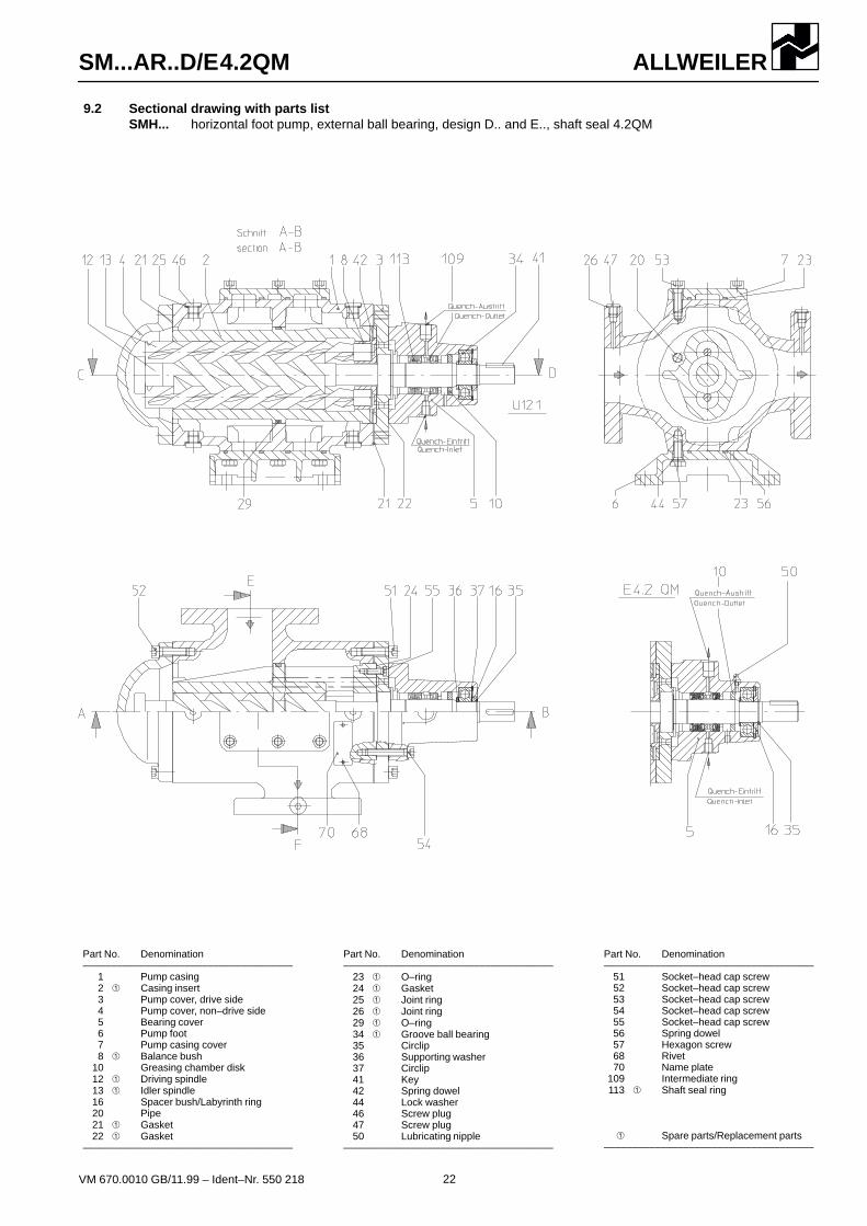
9.2 Sectional drawing with parts listSMH... horizontal foot pump, external ball bearing, design D.. and E.., shaft seal 4.2QM
Part No. Denomination–––––––––––––––––––––––––––––––––––––
1 Pump casing2 � Casing insert3 Pump cover, drive side4 Pump cover, non–drive side5 Bearing cover6 Pump foot7 Pump casing cover8 � Balance bush
10 Greasing chamber disk12 � Driving spindle13 � Idler spindle16 Spacer bush/Labyrinth ring20 Pipe21 � Gasket22 � Gasket
–––––––––––––––––––––––––––––––––––––
Part No. Denomination–––––––––––––––––––––––––––––––––––––
23 � O–ring24 � Gasket25 � Joint ring26 � Joint ring29 � O–ring34 � Groove ball bearing35 Circlip36 Supporting washer37 Circlip41 Key42 Spring dowel44 Lock washer46 Screw plug47 Screw plug50 Lubricating nipple
–––––––––––––––––––––––––––––––––––––
Part No. Denomination–––––––––––––––––––––––––––––––––––––
51 Socket–head cap screw52 Socket–head cap screw53 Socket–head cap screw54 Socket–head cap screw55 Socket–head cap screw56 Spring dowel57 Hexagon screw68 Rivet70 Name plate
109 Intermediate ring113 � Shaft seal ring
� Spare parts/Replacement parts–––––––––––––––––––––––––––––––––––––

ALLWEILERSM...AR..D/E4.2QM
23VM 670.0010 GB/11.99 – Ident–Nr. 550 218
Pump dimensions �Heating
Heating (electrical)Pumpsize
Heatingsteam/heatconveyor Total heating
capacitiy Heating elements 220 V, 50 HzHeating up time of pump
in minutes at ∆t =
k7 k8 k9 p4 p5 q8 u1 H1/H2 H3/H4
capacitiy(2 elements)
W Length ØCon-
nectionKey
width25�C
50�C
75�C
���
�C
4080
120
210280440
660940
1300
546,5631,5718,5
795,5978,51028
114112791380
524,5603,5699,5
792,5868,0954,0
110112401326
484567631
748800921
105011761260
274,5315,5339,5
404,5466,0497,0
551,0709,0771,0
234278271
360398464
500645705
296,5342,5358,5
407,0576,5571,0
591,0748,0825,0
100120145
170175200
225244265
G 1/4G 1/4G 1/4
G 1/4G 3/8G 3/8
G 3/8G 3/8G 1/2
G 3/8G 3/8G 3/8
G 1/2G 1/2G 1/2
G 1/2G 1/2G 1/2
240260300
420460460
6808801000
130150170
190210210
240250280
202020
252525
324040
G 3/4G 3/4G 3/4
G 1G 1G 1
G 1 1/4G 1 1/2G 1 1/2
323232
414141
606060
60 120 240 320
� Further dimensions see dimensions leaflet VM 618/... 2000 for SMH, VM 618... 2001 for SMF, VM 618... 2002 for SMS.
9.3 Heating – not valid for fabricated designSeries SMH, SMF, SMS design ...E = with heating elements for electrical heating
design ...P = with heating cartridge for steam or heat conveyorsdesign ...X = with heating cover for steam or heat conveyors
Design ...E (with 2 heating elements, electric)SMH/SMF 40 bis 1300 SMS 40 bis 1300 Wiring diagram
Screw arrangement atpump footII = SMS 40IV = SMS 80 to 210V = SMS 280 to 940VI = SMS 1300
� Fuse� Thermostat (control
range 0 up to 150�C� Heating elements220 V, 50 Hz
Design ...X (with heating cover) Design ...P (with 2 heating cartridges, steam/heat conveyor)SMH/SMF 40 to 1300 SMS 40 to 1300 Connection – cartridge
Inlet steam/heatconveyor
Outlet steam/heatconveyor
Dimensions in mmAlteration of dimensions reserved

ALLWEILERSM...AR..D/E4.2QM
24VM 670.0010 GB/11.99 – Ident–Nr. 550 218
Subject to technical changes.
ALLWEILER AGWerk RadolfzellPostfach 1140D–78301 RadolfzellAllweilerstraße 1D–78315 RadolfzellGermany� (++ 49) 7732 86 0Fax (++ 49) 7732 86 436E–mail: [email protected]:http://www.allweiler.de