allow smart meter verification to reduce your proving · pdf fileallow smart meter...
TRANSCRIPT
BY TIMOTHY J. CUNNINGHAM and TOM O’BANION, MICRO MOTION, INC.
Allow Smart Meter Verification to Reduce your Proving and Proof-Test Costs
Abstract
Industry and agencies are dedicated to ensuring fair and safe measurement in numerous applications such as fiscal transfer of gases and liquids, environmental compliance and safety systems. Annual or more frequent proving of flowmeters and other devices is common. Coriolis meters are widely known for their stability and linearity over time, suggesting that proving intervals might be extended, reducing proving and proof-test costs.
Smart Meter Verification uses on-board diagnostics to measure the flowtube stiffness, which is directly related to the flow calibration factor. Each verification checks meter stiffness and compares it to a factory baseline. If the stiffness is unchanged, the calibration factor is correct and the meter will meet its mass flow accuracy specification. Smart Meter Verification confirms the accuracy of the measurement and the integrity of the meter providing a means to reduce cost by extending proving intervals.
Smart Meter Verification can be performed under flowing conditions in-situ without requiring any special process conditions. Recent technology advances in Smart Meter Verification allow the stiffness to be measured without interrupting the meter’s process measurements, allowing its use in custody transfer and safety system applications. User data from Smart Meter Verification will be compared with proving data to illustrate the stability of Coriolis calibration and stiffness.
Examples of the acceptance of Smart Meter Verification by agencies such as the Canadian ERCB, ISO, USA EPA, Safety Instrumented Systems (IEC / SIS), and AGA will be presented along with work-practice changes.
Introduction
Coriolis flowmeters are becoming increasingly common in precision flow measurement. Their high accuracy gas and liquid mass flow measurement, along with precise liquid density (concentration, API gravity, etc.), and high turn-down capability makes Coriolis meters a good choice for precision flow. Additionally, Coriolis acceptance is being
KNOWLEDGE
WP-001540, Rev. A/©2012 Micro Motion, Inc. All rights reserved.
driven by the long term stability of their Flow Calibration Factor (FCF), which is a consequence of their lack of moving or wearing parts.
To assure fair and safe measurement, flowmeters are commonly proven or proof-tested at regular intervals. Proving or validation compares the indicated flow measurement to a reference flow measurement. Proof testing is used for Safety Instrumented Systems (SIS) to detect failures within the flowmeter that are not detected by device diagnostics. Flowmeters are also commonly verified by tracking a secondary variable that is highly correlated to the flow measurement. For example, orifice plates can be measured to verify accuracy. Other verification techniques include spindown tests for turbine meters and speed of sound and transducer gain checks for ultrasonic meters.
Micro Motion Coriolis meters offer Smart Meter Verification, a non-intrusive methodology to verify flow tube stiffness. The verification can be done under flowing conditions, in-situ, with no interruption to the process measurements. This flow tube verification complements the long-term stability and linearity associated with Coriolis flowmeters. Flow tubes stiffness can be shown to directly correlate to the flow calibration factor. Verifying that the stiffness is unchanged from the factory baseline confirms that the FCF is still correct. Stable verification results suggest that the proving intervals might be extended. In SIS, proof test frequency is determined by reliability calculations for the given safety loop. The proof test must be performed at least as frequently as specified in the calculation in order to maintain the required safety integrity of the Safety Instrumented Function (SIF).
Because of its simplicity, robustness, and usefulness, Smart Meter Verification is being implemented by users as part of their standard work practices for troubleshooting, ISO9001, and EPA Greenhouse Gas compliance. Efforts towards acceptance of Smart Meter Verification by other regulatory agencies such as USA’s NIST, API, AGA and MID are planned in order to enable other work practice changes.
MICRO MOTION WHITE PAPER
Coriolis Flowmeter Background
Coriolis flowmeter stability
Coriolis meter history shows that there is little variation in the FCF over time. For example, reference Coriolis meters are used to verify the accuracy of manufacturer’s calibration facilities. These meters are checked against a gravimetric standard on a regular basis. Reference meters which are 10+ years old still have the same calibration as the day they were built.
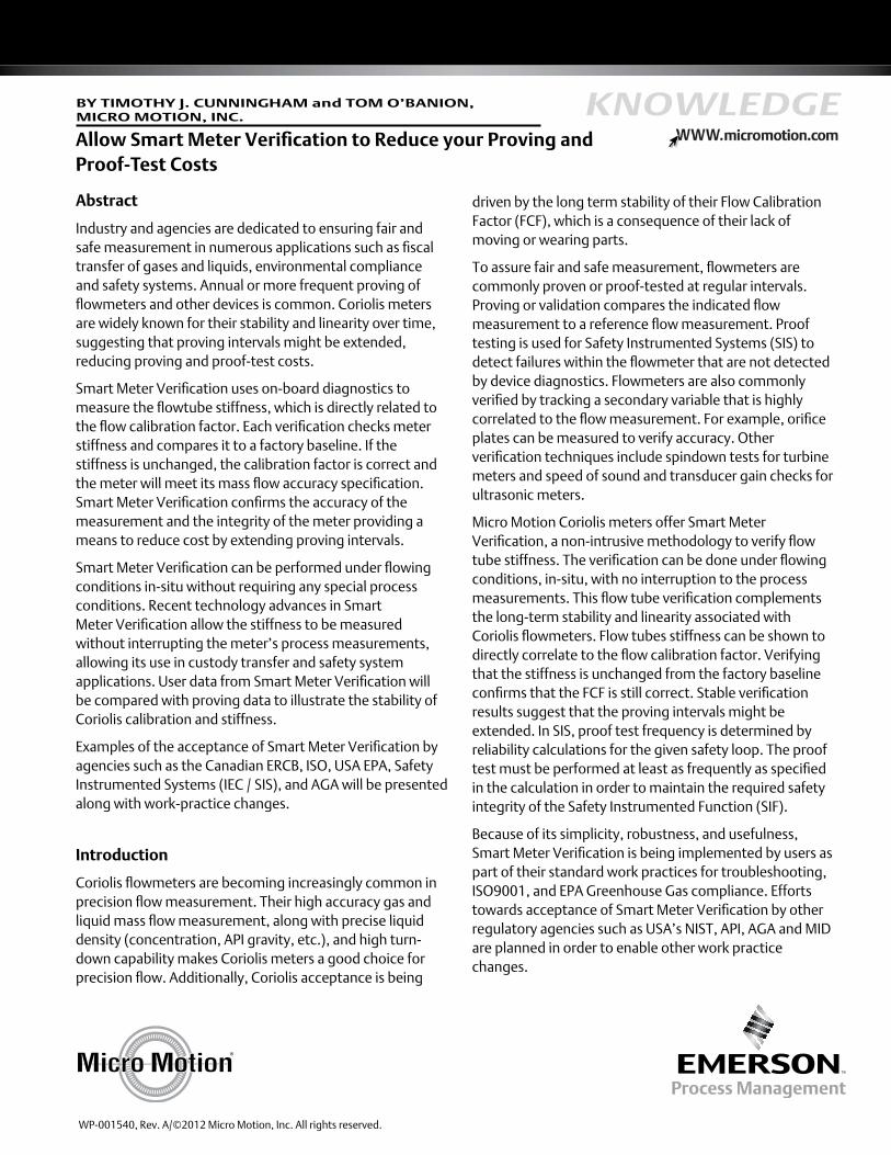
Figure 1. Long-term Coriolis Proving Data
Coriolis meters are commonly proved in the field by comparing the calculated volumetric flow from the Coriolis meter to the standard volume of a prover [2, 3]. Figure 1 shows a plot of the meter factor from six Coriolis meters used in cavern storage. These meters have been in use for as long as 13 years. The meter factors show random variation and some bias in the meter factor. However, the provings generate a meter factor that has a constant mean value over the lifetime of the meter. The proving data say that the meter factor has the same average value as when it left the factory.
A conservative estimate of the cost of the 375 provings in Figure 1 is $200,000 (assuming ~ $500/proving). Provings may be required by regulation or standard procedures. But the data shows that these provings added nothing to the accuracy of the Coriolis flow measurement.
Coriolis flowmeter calibration factor and stiffness
Smart Meter Verification uses the stiffness of the flow tubes as the secondary variable to verify the correctness of the Flow Calibration Factor (FCF). The FCF is the proportionality constant that relates the time delay,dt, to the mass flow rate, .
Equation (1):
Equation (1) can be derived from first principles, for example starting with the Housner differential equation describing a fluid-conveying beam [1, 2]. However, a much simpler dimensional analysis of Equation (1) shows that the FCF has units of stiffness. Rearranging Equation (1)
Equation (2):
shows that the units of the FCF are mass flow rate/time delay. This is shown dimensionally as
Equation (3):
For example, FCF is commonly expressed in units of (gm/sec)/m sec. In a consistent system of units, mass can be represented by force/(acceleration), taking advantage of Newton’s Second Law. Plugging this into equation (3)
Equation (4):
shows very simply that the flow calibration factor has units of stiffness (Force/Length).
The equivalence of FCF and stiffness shows why stiffness is the secondary variable that is highly correlated to the FCF. The problem now becomes one of how to determine the stiffness of the flow tubes.
Meter verification theory
Smart Meter Verification uses techniques from Experimental Modal Analysis and Structural Dynamics theory to very accurately measure the stiffness of the flow tubes using the embedded electronics and onboard pickoff and drive coil and magnets.
Page 2 of 8
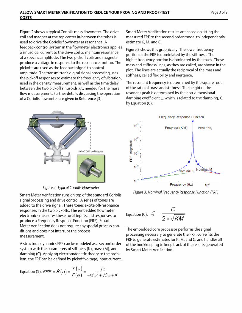
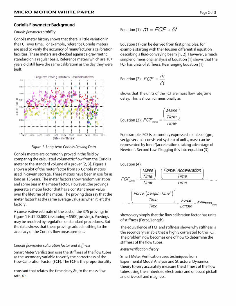
Figure 2 shows a typical Coriolis mass flowmeter. The drive coil and magnet at the top center in-between the tubes is used to drive the Coriolis flowmeter at resonance. A feedback control system in the flowmeter electronics applies a sinusoidal current to the drive coil to maintain resonance at a specific amplitude. The two pickoff coils and magnets produce a voltage in response to the resonance motion. The pickoffs are used as the feedback signal to control amplitude. The transmitter’s digital signal processing uses the pickoff responses to estimate the frequency of vibration, used in the density measurement, as well as the time delay between the two pickoff sinusoids, dt, needed for the mass flow measurement. Further details discussing the operation of a Coriolis flowmeter are given in Reference [3].
Figure 2. Typical Coriolis Flowmeter
Smart Meter Verification runs on top of the standard Coriolis signal processing and drive control. A series of tones are added to the drive signal. These tones excite off-resonance responses in the two pickoffs. The embedded flowmeter electronics measures these tonal inputs and responses to produce a Frequency Response Function (FRF). Smart Meter Verification does not require any special process con-ditions and does not interrupt the process measurement.
A structural dynamics FRF can be modeled as a second order system with the parameters of stiffness (K), mass (M), and damping (C). Applying electromagnetic theory to the prob-lem, the FRF can be defined by pickoff voltage/input current.
Equation (5):
ALLOW SMART METER VERIFICATION TO REDUCE YOUR PROVING AND PROOF-TEST COSTS
Smart Meter Verification results are based on fitting the measured FRF to the second order model to independently estimate K, M, and C.
Figure 3 shows this graphically. The lower frequency portion of the FRF is dominiated by the stiffness. The higher frequency portion is dominated by the mass. These mass and stiffness lines, as they are called, are shown in the plot. The lines are actually the reciprocal of the mass and stiffness, called flexibility and inertance.
The resonant frequency is determined by the square root of the ratio of mass and stiffness. The height of the resonant peak is determined by the non-dimensional damping coefficient z, which is related to the damping, C, by Equation (6).
Figure 3. Nominal Frequency Response Function (FRF)
Equation (6):
The embedded core processor performs the signal processing necessary to generate the FRF; curve fits the FRF to generate estimates for K, M, and C; and handles all of the bookkeeping to keep track of the results generated by Smart Meter Verification.
Page 3 of 8
Results
Smart Meter Verification distills all of its results down to two simple numbers that it presents to the customer. Smart Meter Verification starts with the factory baseline verifications during the standard meter calibration process, which Micro Motion performs as part of its comprehensive diagnostic program. Each Smart Meter Verification measurement is normalized by the average of these stiffnesses and converted into a stiffness uncertainty, which is the percentage change in the measured stiffness from the factory baselines.
Equation (7):
Normalizing the stiffness uncertainty in this way makes it easy to track any changes in the flowmeter by using a format that is convenient to view. (This stiffness uncertainty should not be confused with the term measurement uncertainty as it is used in metrological terms.)
Meter Verification Stability
Figure 4. Smart Meter Verification Stability
The signal processing used in Smart Meter Verification has been designed to enhance the stability of the measurement. Each stiffness uncertainty measurement is the average of the stiffness estimates from many FRFs. In turn, each FRF that is fit is averaged from many individual FRF measurements. This averaging results in a very stable stiffness uncertainty estimate. In-line with standard measurement techniques, the variation in Smart Meter Verification uncertainty is several times better than the base flow accuracy. Figure 4 shows a typical Smart Meter Verification uncertainty plot with a standard deviation of less than 0.01% under laboratory conditions. Note that stiffness uncertainty is calculated for each of the two pickoffs, further
increasing the confidence in the measurement.
Smart Meter Verification uncertainty variation is of course subject to field effects. The specification limits for stiffness uncertainty are set such that under the full range of field effects there is a 3s probability against giving a false alarm. Smart Meter Verification, specification limits, and field effects are discussed more fully in References [4] and [5].
Smart Meter Verification Results
Using the onboard electronics and pickoff and drive transducers to measure the stiffness means that the stiffness verification not only verifies the flow tube stiffness, it also confirms the integrity of the transducers and wiring and the transmitter hardware and software.
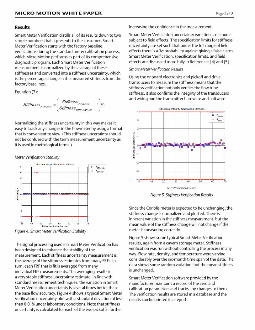
Meter Verification Counter
Figure 5. Stiffness Verification Results
Since the Coriolis meter is expected to be unchanging, the stiffness change is normalized and plotted. There is inherent variation in the stiffness measurement, but the mean value of the stiffness change will not change if the meter is measuring correctly.
Figure 5 shows some typical Smart Meter Verification results, again from a cavern storage meter. Stiffness verification was run without controlling the process in any way. Flow rate, density, and temperature were varying considerably over the six-month time span of the data. The data shows some random variation, but the mean stiffness is unchanged.
Smart Meter Verification software provided by the manufacturer maintains a record of the zero and calibration parameters and tracks any changes to them. The verification results are stored in a database and the results can be printed in a report.
MICRO MOTION WHITE PAPER Page 4 of 8
ALLOW CORIOLIS SMART METER VERIFICATION TO REDUCE YOUR PROVING AND PROOF-TEST COSTS
meter performance.
Canadian ERCB
The Energy Resources Conservation Board (ERCB) is an independent, quasi-judicial agency of the Government of Alberta. It regulates the safe, responsible, and efficient development of Alberta’s energy resources: oil, natural gas, oil sands, coal, and pipelines. Sections 2.5.2.1 and 2.6 of ERCB’s Directive 17 states, “Internal metering diagnostics may be used to determine if the primary measurement element is within acceptable operating parameters and checked at the same required intervals as an internal inspection. Then internal inspection is not required until an alarm or error is generated by the device or as recommended by the manufacturer. The operator must maintain documentation on the diagnostic capability of the measurement system…”
Directive 17 allows Smart Meter Verification to be used to extend proving intervals, which can result in significant cost savings. For example, without Smart Meter Verification a meter might typically be proved 12 times per year. With Smart Meter Verification the proving interval can be extended until the verification triggers an alarm. Since Coriolis meters are not expected to change, that means that a verification alarm will most likely never be triggered. However, proving a Coriolis meter at the initial installation and thereafter on an annual basis would be a good conservative recommendation. Costs for a typical prove might be $200 plus technician time and mileage. A bill of $500 per prove would not be uncommon. With Smart Meter Verification, the total cost savings for the 11 proves obviated by meter verification would be $5,500/year.
ISO9001
The ISO 9000 family of standards are related to quality management systems and designed to help organizations ensure that they meet the needs of customers and other stakeholders. Section 7.6 part a) enables the use of Smart Meter Verification as a complement to calibration:
7.6 Control of monitoring and measuring equipment
The organization shall determine the monitoring and measurement to be undertaken and the monitoring and measuring equipment needed to provide evidence of conformity of product to determine requirements. The organization shall establish processes to ensure that monitoring and measurement can be carried out and are carried out in a manner that is consistent with the monitoring and measurement requirements. Where necessary to ensure valid results, measuring equipment shall:
Page 5 of 8
Discussion
Smart Meter Verification measures stiffness to ensure the integrity of the sensing element, the flow tubes. Additionally the electronics associated with the flow measurement need to be verified. Smart Meter Verification confirms the integrity of the flowmeter electronics by verifying the stiffness with the same transducers, analog electronics, digital electronics, and software used for the flow measurement. Any change in the electronics will cause the stiffness uncertainty to go out of specification. Therefore good stiffness uncertainty confirms both the sensing element and the electronics.
Smart Meter Verification is unlike flowmeter validation methodologies such as proving, in which the output of the unit being tested is compared to a primary flow output. Smart Meter Verifications require several additional checks to confirm overall flowmeter performance. These checks include confirming the software configuration, the flowmeter’s zero, and the proper functioning of the analog outputs. A complete verification might include checking the analog output functionality with the built-in diagnostic/trim functions.
Smart Meter Verification includes a built-in check of the software configuration, comparing it to the previously verified values. Additionally, Smart Meter Verification checks the current zero against the factory zero and the last-verified zero. Smart Meter Verification also provides a graphical output of the results and the ability to print a report of the current verification [6]. All of these features combine to completely check the performance of the entire flowmeter.
A diverse range of meter verification uses has evolved since 2006. The most common is device and process troubleshooting, reflecting Coriolis wide-spread use in process control. More recently, Smart Meter Verification has seen adoption in more regulated applications such as fiscal transfer, safety systems, and the like. The remainder of this paper will discuss several specific application types and the longer term vision for Smart Meter Verification.
Agency Approvals
A number of agencies or regulatory bodies have endorsed or recognized Smart Meter Verification. The technology is widely known for stability and linearity over time, suggesting that proving or proof-test intervals might be extended. These work practice changes can save time and money, while simultaneously assuring fair and safe measurement. Numerous other agencies have expressed interest in learning more about Smart Meter Verification, and conducting tests to further establish the correlation to
a) be calibrated or verified, or both, at specified intervals, or prior to use, against measurement standards traceable to international or national measurement standards; where no such standards exist, the basis used for calibration or verification shall be recorded (see 4.2.4);
USA EPA for Greenhouse Gas
Forty CFR part 98 drove numerous new or improved measurement points in order to comply with EPA regulations concerning emission of Greenhouse Gases. This regulation specified 1-3 year proving intervals for traditional flowmeters such as dp/orifice and turbine. For newer technologies such as Coriolis, advanced techniques such as Smart Meter Verification were recognized, if the manufacturer could prove a correlation to calibration or proving. For many users, Smart Meter Verification drove the technology selection to Coriolis [7].
Safety Instrumented Systems (SIS)
International Electrotechnical Commission (IEC) efforts to harmonize the global approach to Process Safety have driven users to invest heavily in education, training, and risk reduction. Coriolis is widely used in critical process control, and in certain SIS applications.
The technology is inherently well suited to safety loops due to the simplicity of the sensor and power of the transmitter diagnostics. Proof-testing is a set of prescribed checks to detect failures within the meter. Of main concern are undetected failures that prevent the safety function from performing its intended function. High safety scores enable Micro Motion Coriolis to be “SIL-3 capable.”
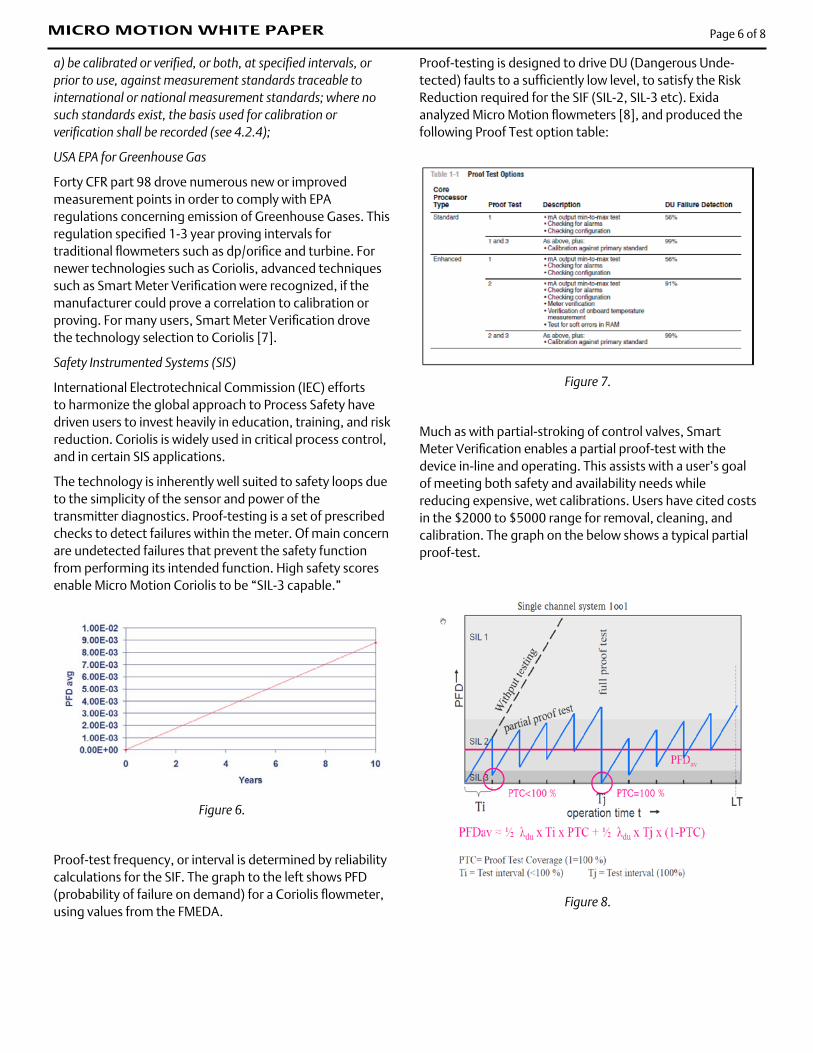
Figure 6.
Proof-test frequency, or interval is determined by reliability calculations for the SIF. The graph to the left shows PFD (probability of failure on demand) for a Coriolis flowmeter, using values from the FMEDA.
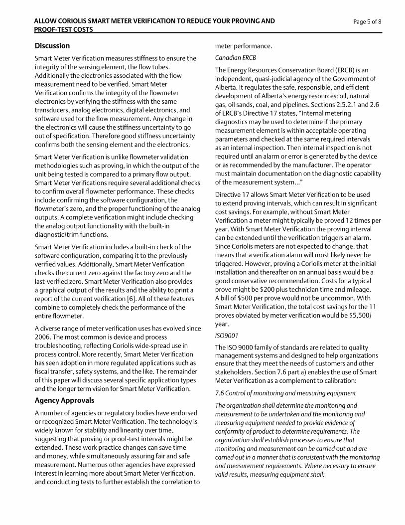
Proof-testing is designed to drive DU (Dangerous Unde-tected) faults to a sufficiently low level, to satisfy the Risk Reduction required for the SIF (SIL-2, SIL-3 etc). Exida analyzed Micro Motion flowmeters [8], and produced the following Proof Test option table:
Figure 7.
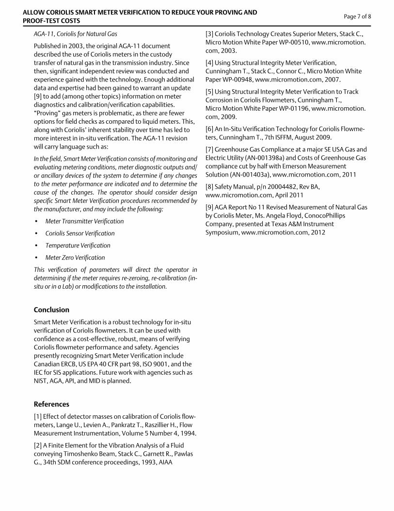
Much as with partial-stroking of control valves, Smart Meter Verification enables a partial proof-test with the device in-line and operating. This assists with a user’s goal of meeting both safety and availability needs while reducing expensive, wet calibrations. Users have cited costs in the $2000 to $5000 range for removal, cleaning, and calibration. The graph on the below shows a typical partial proof-test.
Figure 8.
Page 6 of 8MICRO MOTION WHITE PAPER
AGA-11, Coriolis for Natural Gas
Published in 2003, the original AGA-11 document described the use of Coriolis meters in the custody transfer of natural gas in the transmission industry. Since then, significant independent review was conducted and experience gained with the technology. Enough additional data and expertise had been gained to warrant an update [9] to add (among other topics) information on meter diagnostics and calibration/verification capabilities. “Proving” gas meters is problematic, as there are fewer options for field checks as compared to liquid meters. This, along with Coriolis’ inherent stability over time has led to more interest in in-situ verification. The AGA-11 revision will carry language such as:
In the field, Smart Meter Verification consists of monitoring and evaluating metering conditions, meter diagnostic outputs and/or ancillary devices of the system to determine if any changes to the meter performance are indicated and to determine the cause of the changes. The operator should consider design specific Smart Meter Verification procedures recommended by the manufacturer, and may include the following:
• Meter Transmitter Verification
• Coriolis Sensor Verification
• Temperature Verification
• Meter Zero Verification
This verification of parameters will direct the operator in determining if the meter requires re-zeroing, re-calibration (in-situ or in a Lab) or modifications to the installation.
Conclusion
Smart Meter Verification is a robust technology for in-situ verification of Coriolis flowmeters. It can be used with confidence as a cost-effective, robust, means of verifying Coriolis flowmeter performance and safety. Agencies presently recognizing Smart Meter Verification include Canadian ERCB, US EPA 40 CFR part 98, ISO 9001, and the IEC for SIS applications. Future work with agencies such as NIST, AGA, API, and MID is planned.
References
[1] Effect of detector masses on calibration of Coriolis flow-meters, Lange U., Levien A., Pankratz T., Raszillier H., Flow Measurement Instrumentation, Volume 5 Number 4, 1994.
[2] A Finite Element for the Vibration Analysis of a Fluid conveying Timoshenko Beam, Stack C., Garnett R., Pawlas G., 34th SDM conference proceedings, 1993, AIAA
[3] Coriolis Technology Creates Superior Meters, Stack C., Micro Motion White Paper WP-00510, www.micromotion.com, 2003.
[4] Using Structural Integrity Meter Verification, Cunningham T., Stack C., Connor C., Micro Motion White Paper WP-00948, www.micromotion.com, 2007.
[5] Using Structural Integrity Meter Verification to Track Corrosion in Coriolis Flowmeters, Cunningham T., Micro Motion White Paper WP-01196, www.micromotion.com, 2009.
[6] An In-Situ Verification Technology for Coriolis Flowme-ters, Cunningham T., 7th ISFFM, August 2009.
[7] Greenhouse Gas Compliance at a major SE USA Gas and Electric Utility (AN-001398a) and Costs of Greenhouse Gas compliance cut by half with Emerson Measurement Solution (AN-001403a), www.micromotion.com, 2011
[8] Safety Manual, p/n 20004482, Rev BA, www.micromotion.com, April 2011
[9] AGA Report No 11 Revised Measurement of Natural Gas by Coriolis Meter, Ms. Angela Floyd, ConocoPhillips Company, presented at Texas A&M Instrument Symposium, www.micromotion.com, 2012
Page 7 of 8ALLOW CORIOLIS SMART METER VERIFICATION TO REDUCE YOUR PROVING AND PROOF-TEST COSTS
MICRO MOTION WHITE PAPER Page 8 of 8
© 2012 Micro Motion, Inc. All rights reserved.The Micro Motion and Emerson logos are trademarks and service marks of Emerson Electric Co. Micro Motion, ELITE, MVD, ProLink, MVD Direct Connect, and PlantWeb are marks of one of the Emerson Process Management family of companies. All other trademarks are property of their respective owners.
Micro Motion supplies this publication for informational purposes only. While every effort has been made to ensure accuracy, this publication is not intended to make performance claims or process recommendations. Micro Motion does not warrant, guarantee, or assume any legal liability for the accuracy, completeness, timeliness, reliability, or usefulness of any information, product, or process described herein. We reserve the right to modify or improve the designs or specifications of our products at any time without notice. For actual product information and recommendations, please contact your local Micro Motion representative.
Micro Motion Japan Emerson Process Management 1-2-5 Higashi ShinagawaShinagawa-kuTokyo 140-0002 JapanT +81 3 5769-6800F +81 3 5769-6840
Micro Motion Asia Emerson Process Management 1 Pandan CrescentSingapore 128461Rebuplic of SingaporeT +65 6777-8211F +81 6770-8003
Micro Motion, Inc. USA Worldwide Headquarters 7070 Winchester Circle Boulder, Colorado USA 80301 T +1 303-527-5200T +1 800-522-6277 F +1 303-530-8459
Micro Motion Europe Emerson Process Management Neonstraat 16718 WX EdeThe NetherlandsT +31 (0) 318 495 555F +31 (0) 318 495 556