ali-ipz5030 series ip ptz camera installation guideali-ipz5030 series ip ptz camera . installation...
TRANSCRIPT

ALI-IPZ5030 Series IP PTZ Camera Installation Guide
Products: ALI-IPZ5030T, ALI-IPZ5030RT
ALI-IPZ5030RT Camera
ALI-IPZ5030T Camera
PLEASE READ THIS MANUAL BEFORE USING YOUR CAMERAS, and always follow the instructions for safety and proper use. Save this manual for future reference.
ALI-IPZ5030_CM 7/15/14

ii
CAUTION
FCC Caution: To assure continued compliance, use only shielded interface cables when connecting to computer or peripheral devices. Any changes or modifications not expressly approved by the party responsible for compliance could void the user’s authority to operate this equipment.
NOTE
This equipment has been tested and found to comply with the limits for a Class “A” digital device, pursuant to Part 15 of the FCC Rules. These limits are designed to provide reasonable protection against harmful interference when the equipment is operated in a commercial environment. This equipment generates, uses, and can radiate radio frequency energy and, if not installed and used in accordance with the instruction manual, may cause harmful interference to radio communications.
LEGAL NOTICE
Observint Technologies (Observint) products are designed to meet safety and performance standards with the use of specific Observint authorized accessories. Observint disclaims liability associated with the use of non-Observint authorized accessories.
The recording, transmission, or broadcast of any person’s voice without their consent or a court order is strictly prohibited by law.
Observint makes no representations concerning the legality of certain product applications such as the making, transmission, or recording of video and/or audio signals of others without their knowledge and/or consent. We encourage you to check and comply with all applicable local, state, and federal laws and regulations before engaging in any form of surveillance or any transmission of radio frequencies.
ALIBI and the ALIBI logo are trademarks of Observint.
Microsoft, Windows, and Internet Explorer are either registered trademarks or trademarks of Microsoft Corporation in the United States and/or other countries. Android is a trademark of Google Inc. Use of this trademark is subject to Google Permissions. Apple, iPhone, iPod touch, and iPad are registered trademarks of Apple Inc.
Other trademarks and trade names may be used in this document to refer to either the entities claiming the marks and names or their products. Observint disclaims any proprietary interest in trademarks and trade names other than its own.
No part of this document may be reproduced or distributed in any form or by any means without the express written permission of Observint, Inc.
© 2014 by Observint Technologies. All Rights Reserved. 11000 N. Mopac Expressway, Building 300, Austin, TX 78759 For Sales and Support, contact your distributor.

iiiALI-IPZ5030 Series IP PTZ Camera Installation Guide
SAFETY INSTRUCTIONS
Regulatory information
FCC information
FCC compliance: This equipment has been tested and found to comply with the limits for a digital device, pursuant to part 15 of the FCC Rules. These limits are designed to provide reasonable protection against harmful interference when the equipment is operated in a commercial environment. This equipment generates, uses, and can radiate radio frequency energy and, if not installed and used in accordance with the instruction manual, may cause harmful interference to radio communications. Operation of this equipment in a residential area is likely to cause harmful interference in which case the user will be required to correct the interference at his own expense.
FCC conditions
This device complies with part 15 of the FCC Rules. Operation is subject to the following two conditions:
1. This device may not cause harmful interference.
2. This device must accept any interference received, including interference that may cause undesired operation.
Preventive and Cautionary Tips
Before connecting and operating your cameras, please be advised of the following:
• Ensure environmental conditions meet factory specifications.• Major shocks or jolts to the unit as a result of dropping it may cause damage to the sensitive electronics within the unit.• Use the device in conjunction with an UPS if possible.
Safety Instructions
These instructions are intended to ensure that user can use the product correctly to avoid danger or property loss.
The precaution measure is divided into Warnings and Cautions:
• Warnings: Neglecting any of the warnings may cause serious injury or death.• Cautions: Neglecting any of the cautions may cause injury or equipment damage.
Warnings
• All the electronic operation should be strictly compliance with the electrical safety regulations, fire prevention regulations and other related regulations in your local region.
• Do not connect several devices to one power adapter as adapter overload may cause over-heat or fire hazard.• Please make sure that the power has been disconnected before you wire, install or dismantle the camera.

iv
• If smoke, odors or noise rise from the device, turn off the power at once and unplug the power cable, and then please contact the service center.
• If the product does not work properly, please contact your dealer or the nearest service center. Never attempt to disassemble the speed dome yourself. (We shall not assume any responsibility for problems caused by unauthorized repair or maintenance.)
Cautions
• Do not drop the dome or subject it to physical shock, and do not expose it to high electromagnetism radiation. Avoid the equipment installation on vibrations surface or places subject to shock (ignorance can cause equipment damage).
• Do not place the dome in extremely hot, cold, dusty or damp locations, otherwise fire or electrical shock will occur. The operating temperature should be -22 °F ~ 149 °F (-30 °C ~ 65 °C).
• The dome cover for indoor use shall be kept from rain and moisture.• Exposing the equipment to direct sun light, low ventilation or heat source such as heater or radiator is forbidden (ignorance can
cause fire danger).• Do not aim the speed dome at the sun or extra bright places. A blooming or smear may occur otherwise (which is not a
malfunction however), and affecting the endurance of sensor at the same time.• Please use the provided glove when open up the dome cover, avoid direct contact with the dome cover, because the acidic
sweat of the fingers may erode the surface coating of the dome cover.• Please use a soft and dry cloth when clean inside and outside surfaces of the dome cover, do not use alkaline detergents.• Please keep all packaging for future use. In case of a failure, use the original packaging to return the camera to the factory.
Transportation without the original packaging may result in damage to the camera and incur additional costs.
Read these instructions and keep them in a safe place for future reference.
• Please refer all work related to the installation of this product to qualified service personnel or system installers.• Do not operate the camera outside of its specified temperature, humidity or power source ratings.• Install the unit away from heat sources such as radiators, heat registers and stoves.• Installation of the unit near consumer electronics devices, such as stereo receiver/amplifiers and televisions, is permitted as
long as the air surrounding the terminal does not exceed the above mentioned temperature range.• Handle the camera with care. Do not drop or shake, as this may damage it. • Do not use strong or abrasive detergents when cleaning the surfaces of this product. When dirt is hard to remove, use a mild
detergent and wipe gently.• Save your system configuration. • Distributing, copying, disassembling, reverse compiling, reverse engineering, and exporting, in violation of export laws, the
software provided with this product is expressly prohibited.

vALI-IPZ5030 Series IP PTZ Camera Installation Guide
TABLE OF CONTENTS
Table of Contents
SECTION 1 Overview . . . . . . . . . . . . . . . . . . . . . . . . . . . . . . . . . . . . . . . . . . . . . . . . . . . . . . . . . . . . . . . . . . . . . . . . . . 11.1 Features . . . . . . . . . . . . . . . . . . . . . . . . . . . . . . . . . . . . . . . . . . . . . . . . . . . . . . . . . . . . . . . . . . . . . . . . . . . .21.2 What’s in the box . . . . . . . . . . . . . . . . . . . . . . . . . . . . . . . . . . . . . . . . . . . . . . . . . . . . . . . . . . . . . . . . . . . .31.3 Accessories . . . . . . . . . . . . . . . . . . . . . . . . . . . . . . . . . . . . . . . . . . . . . . . . . . . . . . . . . . . . . . . . . . . . . . . . . .3
SECTION 2 Installation . . . . . . . . . . . . . . . . . . . . . . . . . . . . . . . . . . . . . . . . . . . . . . . . . . . . . . . . . . . . . . . . . . . . . . . . 82.1 Remove the packaging from the camera . . . . . . . . . . . . . . . . . . . . . . . . . . . . . . . . . . . . . . . . . . . . . . . . .9
2.1.1 Remove ALI-IPZ5030T packaging . . . . . . . . . . . . . . . . . . . . . . . . . . . . . . . . . . . . . . . . . . . . . . . . . .92.1.2 Remove ALI-IPZ5030RT packaging . . . . . . . . . . . . . . . . . . . . . . . . . . . . . . . . . . . . . . . . . . . . . . . .10
2.2 Install an SD card in the camera (optional) . . . . . . . . . . . . . . . . . . . . . . . . . . . . . . . . . . . . . . . . . . . . .102.3 Camera wall mount installation . . . . . . . . . . . . . . . . . . . . . . . . . . . . . . . . . . . . . . . . . . . . . . . . . . . . . . .112.4 Ceiling mounting . . . . . . . . . . . . . . . . . . . . . . . . . . . . . . . . . . . . . . . . . . . . . . . . . . . . . . . . . . . . . . . . . . .132.5 Connecting the cables . . . . . . . . . . . . . . . . . . . . . . . . . . . . . . . . . . . . . . . . . . . . . . . . . . . . . . . . . . . . . . .14
SECTION 3 Configure Network Access . . . . . . . . . . . . . . . . . . . . . . . . . . . . . . . . . . . . . . . . . . . . . . . . . . . . . . . . . . . 17SECTION 4 Remote login . . . . . . . . . . . . . . . . . . . . . . . . . . . . . . . . . . . . . . . . . . . . . . . . . . . . . . . . . . . . . . . . . . . . . . 20
4.1 Additional configuration steps . . . . . . . . . . . . . . . . . . . . . . . . . . . . . . . . . . . . . . . . . . . . . . . . . . . . . . . .24APPENDIX A Specifications . . . . . . . . . . . . . . . . . . . . . . . . . . . . . . . . . . . . . . . . . . . . . . . . . . . . . . . . . . . . . . . . . . . . . 25APPENDIX B Lightning and Surge Protection . . . . . . . . . . . . . . . . . . . . . . . . . . . . . . . . . . . . . . . . . . . . . . . . . . . . . . 28APPENDIX C 24 Vac Wire Gauge and Transmission Distance . . . . . . . . . . . . . . . . . . . . . . . . . . . . . . . . . . . . . . . . . . 29

vi
TABLE OF CONTENTS
1ALI-IPZ5030 Series IP PTZ Camera Installation Guide
SECTION 1: OVERVIEW
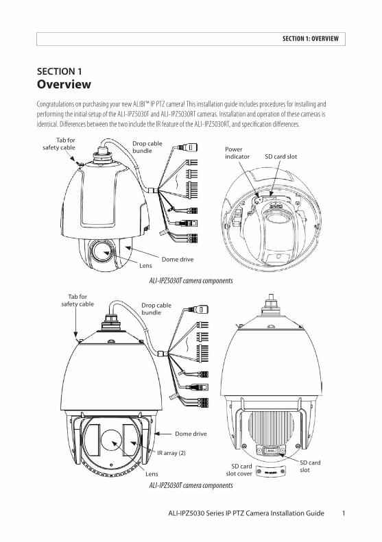
SECTION1 OverviewCongratulations on purchasing your new ALIBI™ IP PTZ camera! This installation guide includes procedures for installing and performing the initial setup of the ALI-IPZ5030T and ALI-IPZ5030RT cameras. Installation and operation of these cameras is identical. Differences between the two include the IR feature of the ALI-IPZ5030RT, and specification differences.
Drop cable bundle
Tab for safety cable
SD card slotPower indicator
Dome driveLens
ALI-IPZ5030T camera components
Drop cable bundle
IR array (2)
Lens
SD card slotSD card
slot cover
Tab for safety cable
Dome drive
ALI-IPZ5030T camera components

2
1.1 Features
• Limit Stops: The dome can be programmed to move within the limit stops (left/right, up/down).• Scan Modes: The dome provides five scan modes: auto scan, tilt scan, frame scan, random scan and panorama scan.• Preset Freezing: This feature freezes the scene on the monitor when the dome is moving to a preset. This allows for smooth
transition from one preset scene to another. It also guarantees that masked area will not be revealed when the dome is moving to a preset.
• Presets: A preset is a predefined image position. When the preset is called, the dome will automatically move to the defined position. The presets can be added, modified, deleted and called.
• Label Display: The on-screen label of the preset title, azimuth/elevation, zoom, time and dome name can be displayed on the monitor. The displays of time and speed dome name can be programmed.
• Auto Flips: In manual tracking mode, when a target object goes directly beneath the dome, the video will automatically flips 180 degrees in horizontal direction to maintain continuity of tracking. This function can also be realized by auto mirror image depending on different camera models.
• Privacy Mask: This function allows you to block or mask certain area of a scene, for preventing the personal privacy from recording or live viewing. A masked area will move with pan and tilt functions and automatically adjust in size as the lens zooms telephoto and wide.
• 3D Positioning: In the client software, use the left key of mouse to click on the desired position in the video image and drag a rectangle area in the lower right direction, then the dome system will move the position to the center and allow the rectangle area to zoom in. Use the left key of mouse to drag a rectangle area in the upper left direction to move the position to the center and allow the rectangle area to zoom out.
• Proportional Pan/Tilt: Proportional pan/tilt automatically reduces or increases the pan and tilt speeds according to the amount of zoom. At telephoto zoom settings, the pan and tilt speeds will be slower than at wide zoom settings. This keeps the image from moving too fast on the live view image when there is a large amount of zoom.
• Auto Focus: The auto focus enables the camera to focus automatically to maintain clear video images.• Day/Night Auto Switch: The speed domes deliver color images during the day. And as light diminishes at night, the speed
domes switch to night mode and deliver black and white images with high quality.• Slow Shutter: In slow shutter mode, the shutter speed will automatically slow down in low illumination conditions to
maintain clear video images by extending the exposure time. The feature can be enabled or disabled.• Backlight Compensation (BLC): If you focus on an object against strong backlight, the object will be too dark to be seen
clearly. The BLC (Backlight Compensation) function can compensate light to the object in the front to make it clear, but this causes the over-exposure of the background where the light is strong.
• Wide Dynamic Range (WDR): The wide dynamic range (WDR) function helps the camera provide clear images even under back light circumstances. When there are both very bright and very dark areas simultaneously in the field of view, WDR balances the brightness level of the whole image and provide clear images with details. This feature varies depending on speed dome models.
• White Balance (WB): White balance can remove the unrealistic color casts. White balance is the white rendition function of the camera to adjust the color temperature according to the environment automatically.
• Patrol: A patrol is a memorized series of pre-defined preset function. The scanning speed between two presets and the dwell time at the preset are programmable.
• Pattern: A pattern is a memorized series of pan, tilt, zoom, and preset functions. By default the focus and iris are in auto status during the pattern is being memorized.
SECTION 1: OVERVIEW

3ALI-IPZ5030 Series IP PTZ Camera Installation Guide
SECTION 1: OVERVIEW
• Power Off Memory: The dome supports the power off memory capability with the predefined resume time. It allows the dome to resume its previous position after power is restored.
• Scheduled Task: A time task is a preconfigured action that can be performed automatically at a specific date and time. The programmable actions include: auto scan, random scan, patrol 1-8 ,pattern 1-4, preset 1-8,frame scan, panorama scan, tilt scan, day, night, reboot, PT adjust, Aux Output, etc.
• Park Action: This feature allows the dome to start a predefined action automatically after a period of inactivity.• User Management: The dome allows you to edit users with different levels of permission, in the admin login status.
Multiple users are allowed to access and control the same network speed dome via network simultaneously.• 3D Digital Noise Reduction: Comparing with the general 2D digital noise reduction, the 3D digital noise reduction function
processes the noise between two frames besides processing the noise in one frame. The noise will be much less and the video will be clearer.
1.2 What’s in the box
Your camera includes:
• PTZ camera assembly• Pendant adapter• Hi-Power PoE injector • Safety cable• Gloves• Hex L-wrench (2 for ALI-IPZ5030RT)• Thread tape• Software and documentation CD• Quick installation guide (this document)
1.3 Accessories
The following accessories are available for the ALIBI ALI-IPZ5030T and ALI-IPZ5030RT cameras. Mounting bracket detail is shown below.
Model Type
ALI-PTZCL Ceiling Mount Bracket
ALI-PTZWB Wall Mount Bracket
ALI-PTZPM Pole Mount PTZ Bracket
ALI-PTZCM Corner Mount PTZ Bracket

4
ALI-PTZCL: Ceiling Mount Bracket
The Ceiling Mount Bracket is suitable for outdoor ceiling mounting.
3.52" dia.
0.39" dia. (4)
2.24"
4.57" dia.
SECTION 2: NETWORK CONNECTION

5ALI-IPZ5030 Series IP PTZ Camera Installation Guide
SECTION 2: NETWORK CONNECTION
ALI-PTZWB: Wall Mount Bracket
The Wall Mount Bracket is suitable for indoor and outdoor wall mounting.
0.33" dia. (4)
G 1.5"
6.30
"
7.64
"
2.95"
3.82"12.2"

6
ALI-PTZPM: Pole Mount PTZ Bracket
The Pole Mount Bracket is suitable for outdoor pole mounting. The straps can attach to a 2.64” ~ 5.00” diameter pole.
2.68
"2.
68"7.
64"
7.64
"
5.63"
3.94" dia.
G 1.5"
12.2" 4.61"
SECTION 2: NETWORK CONNECTION

7ALI-IPZ5030 Series IP PTZ Camera Installation Guide
SECTION 3: REMOTE ACCESS
ALI-PTZCM: Corner Mount PTZ Bracket
7.64
"
6.96"
G 1.5"
16.52"

8
SECTION2 InstallationBefore you start
• Check the package contents and make sure that the device in the package is in good condition and all the assembly parts are included:
— PTZ camera assembly— Pendant adapter— Thread tape— Hi-Power PoE injector — Safety cable— Gloves— Hex L-wrench (2 for ALI-IPZ5030RT)— Software and documentation CD— Quick installation guide (this document)
• Make sure the mounting surface and fasteners are strong enough to withstand at least 8 times the weight of the camera assembly and the mounting bracket.
• For cement walls, use an expansion screw to secure the mounting bracket.
CAUTION Do not carry the camera by the drop cable.
For outdoor installations, refer to “APPENDIX B Lightning and Surge Protection” on page 28 for additional installation considerations.
SECTION 2: INSTALLATION

9ALI-IPZ5030 Series IP PTZ Camera Installation Guide
SECTION 2: INSTALLATION CESS
2.1 Remove the packaging from the camera
2.1.1 RemoveALI-IPZ5030Tpackaging
1. Remove the camera from the shipping box and protective plastic bag.
1. Loosen the two lock screws as shown in the following figure.
Lock screw
Back box
Lower dome
Lock screw
ALI-IPZ5030T camera assembly
2. Remove the lower dome and remove the protective foam and tape shown below. Be very careful not to touch the camera lens.
Protective foam
Protective tape
Remove protective foam
3. Reattach the lower dome.

10
2.1.2 RemoveALI-IPZ5030RTpackaging
1. Remove the camera from the shipping box and protective plastic bag.
2. Remove the tape from the dome drive.
Tape
2.2 Install an SD card in the camera (optional)
The SD card in the provides in-camera (local) storage for log information and locally stored video and capture files. Cameras without an SD card cannot provide camera log information, which is valuable for maintenance purposes. Your camera will accommodate an SD card with up to 32 GB of storage.
The location of the SD card slot is different in the ALI-IPZ5030T and ALI-IPZ5030RT cameras. See below.
SD card slot
SD card slot cover
Back of dome drive
SD card slot
Dome drive
Lens
SD Card slots in ALI-IPZ5030T (left) and ALI-IPZ5030RT (right)
SECTION 2: INSTALLATION

11ALI-IPZ5030 Series IP PTZ Camera Installation Guide
Insert SD card into the ALI-IPZ5030T camera
1. Open the lower dome to access the dome drive.
2. Find the SD card slot near the camera lens.
3. Insert the SD card (up to 32 GB) until it is fully seated.
4. Reattach the lower dome.
Insert SD card into the ALI-IPZ5030RT camera
1. Use a Phillips #2 screw driver to remove the SD card slot cover, located on the back of the dome drive.
2. Insert the SD card (up to 32 GB) until it is fully seated.
3. Reattach the SD card slot cover.
2.3 Camera wall mount installation
Following the instructions below to install the camera using the ALI-PTZWB Wall Mount Bracket.
Instructions for mounting the camera with a ALI-PTZPM Pole Mount PTZ Bracket or ALI-PTZCM Corner Mount PTZ Bracket are very similar. For these brackets, use the instructions below as a guide.
1. Determine the best mounting screws and hardware to anchor the mounting bracket with the camera to the mounting surface. Use the following guidelines:
— For cement wall mounting, use the expansion screw to anchor the bracket. — For wooden wall mounting, use self-tapping screw to anchor the bracket.— Make sure that the wall is strong enough to withstand more than 8 times the weight of the camera and the bracket.
2. Using the mounting bracket as a template, mark the location of the mounting screw holes on the mounting surface. Also mark the location of a hole for the camera drop cable. The drop cable will be routed through the mounting bracket and through the mounting surface.
3. Drill holes in the mounting screws and hardware. Also, drill a 1½” diameter hole in the mounting surface for the drop cable.
4. Apply two wrap of the thread tape provided onto the treads of the pendant adapter (see below)
SECTION 2: INSTALLATION

12
Wrap with thread tape
Bracket
Pendant adapter
Pendant adapter set screw
Lock screw (2)
Loop for safety cable
Attach pendant adapter to mounting bracket
5. Screw the pendant adapter onto the end of the mounting bracket. Tighten the set screw to secure the adapter to the bracket.
6. Clip one end of the safety cable to the tab on the top of the camera assembly.
7. Route the camera drop cable through the mounting bracket, then clip the safety cable onto the loop in the mounting bracket.
Drop cable
Pendant adapterAlign
marks
Safety cable
Coupling
Pendant adapter
Back box
8. Fit the camera coupling into the pendant adapter, then twist the camera to align the marks on the pendant adapter and the camera back box. See the figure above.
9. Tighten the two lock screws on the pendant adapter to secure the camera to the mounting bracket.
10. Feed the camera drop cable through hole drilled at the mounting location, then anchor the mounting bracket to the wall.
SECTION 2: INSTALLATION

13ALI-IPZ5030 Series IP PTZ Camera Installation Guide
2.4 Ceiling mounting
Following the instructions below to install the camera using the ALI-PTCL Ceiling Mount Bracket.
1. Determine the best mounting screws and hardware to anchor the mounting bracket with the camera to the mounting surface. Use the following guidelines:
— For cement ceiling mounting, use the expansion screw to anchor the bracket. — For wooden ceiling mounting, use self-tapping screw to anchor the bracket.— Make sure that the ceiling is strong enough to withstand more than 8 times the weight of the camera and the bracket.
2. Using the mounting bracket as a template, mark the location of the mounting screw holes on the ceiling.
3. If the camera drop cable will be routed through the ceiling, mark the location of a hole for the camera drop cable. The drop cable will be routed through the mounting bracket and can be routed either through the mounting surface or out the side of the mounting bracket.
4. Drill holes in the mounting screws and hardware. Also, drill a 1½" diameter hole in the mounting surface for the drop cable.
5. Clip one end of the safety cable to the tab on the top of the camera assembly.
6. Route the camera drop cable through the mounting bracket, then clip the safety cable onto the loop in the mounting bracket.
Pendant adapter Ceiling
Coupling
Drop cable
Safety cable
Align marks
Back box
Lock screw
7. Fit the camera coupling into the ceiling mounting bracket, then twist the bracket to align the marks on the bracket and the camera back box. See the figure above.
8. Tighten the two lock screws on the ceiling bracket to secure the camera to the mounting bracket.
9. Feed the camera drop cable through hole drilled at the mounting location, then anchor the mounting bracket to the ceiling.
SECTION 2: INSTALLATION

14
SECTION 2: INSTALLATION
2.5 Connecting the cables
Drop cables for the ALI-IPZ5030T and ALI-IPZ5030RT are the same. However, the power requirements for differ.
Network (LAN) cableDrop cable bundle
Alarm Output cables
Video cable
Audio cable
RS-485 cable
Alarm Input cables
Power cable (24 Vac)
Connect the camera to other devices as needed in the order shown below.
Alarm Output cables
The alarm output drop cable provides four wires, OUT1 and COM1 (common), and OUT2 and COM2. These wires are color coded and labeled.
Alarm Input cables
The alarm input drop cable provides eight wires, ALARM_IN1 .. ALARM_IN7, and GND (ground). These wires are color coded and labeled.
Audio cable
The Audio drop cable provides three wires: Audio In, Audio Out, and ground. These wires are color coded and labeled.
Connect the Audio In and ground wires to a line level audio input source. The input signal must be 2 ~ 2.4 Vp-p at 1 KΩ ± 10% input impedance.

15ALI-IPZ5030 Series IP PTZ Camera Installation Guide
SECTION 2: INSTALLATION
Connect the Audio Out and ground wires to a line level audio receiver (impedance 600 Ω).
Alarm inputs can be either normally open (N.O.) or normally closed (N.C.), configurable in the camera firmware.
RS-485 cables
Connect the RS-485 drop cable wires to an RS-485 or, or DVR/NVR with an RS-485 network interface for control of PTZ features. PTZ features can also be controlled through the camera network (browser) interface, and through a supported NVR PTZ control panel. These wires are color coded and labeled.
Video cables
The video drop cable provides a BNC connector with a composite NTSC signal for connection to any compatible monitor. The feature is useful for maintenance and for showing the live view display on a local monitor.
Network (LAN) cable
Connect the network LAN drop cable to a router (switch) through an Ethernet drop cable. In some network configurations, the LAN cable can connect directly to a Network Video Recorder (NVR) with a built-in network switch.
The LAN cable can also provide Hi-PoE to the camera. A Hi-PoE injector is provided for powering mode. A typical PoE injector is shown below.
Injector status LEDs
LAN cables for DATA IN (to network switch) and DATA and POWER OUT (to camera)
Ground wirePort labeling
To use the injector:
1. Connect the injector ground wire to an earth ground terminal. (NOTE: Not all PoE injectors have a ground wire.)
2. Connect a LAN drop cable between the network switch and the DATA IN port on the injector.
3. Connect a LAN drop cable between the injector DATA and POWER OUT port and the camera LAN drop cable.

16
4. Plug the power cable provided (not shown) into the back of the injector, then into a standard 120 Vac electrical outlet. When power is applied to the injector, the camera will power on and a system information display will appear for 2 minutes on top of the live video image from the camera. Verify that the information on the display is intelligible.
Typical System Information display
Power cables
The power drop cables are used to provide 24 Vac power to the camera. Refer to “APPENDIX C 24 Vac Wire Gauge and Transmission Distance” on page 29 for more information.
When power is applied to the injector, the camera will power on and a system information display will appear for 2 minutes on top of the live video image from the camera. Verify that the information on the display is intelligible (see above).
If the camera is powered through the LAN cable using a PoE injector, application of power through this cable is optional.
SECTION 2: INSTALLATION
17ALI-IPZ5030 Series IP PTZ Camera Installation Guide
SECTION3 Configure Network AccessAfter the camera is powered on, an initial network configuration setup should be performed. This procedure includes:
• Installing the ALIBI Discover tool• Setting up the camera network configuration
For more information about configuring your ALIBI camera, refer to the ALIBI™ IP Camera Software User Manual provided on the software and documentation CD with your camera.
Step 1. Install the ALIBI Discover Tool
The ALIBI Discover Tool is a software utility used to “discover” ALIBI cameras and NVRs/DVRs installed on the LAN and change their network settings. The tool is provided on the CD with your camera. To use the tool:
1. Insert the software CD provided with your camera into an optical drive on the Microsoft Windows computer you will use to access your camera on the LAN.
2. On the CD, find the folder that contains the ALIBI Discover Tool.
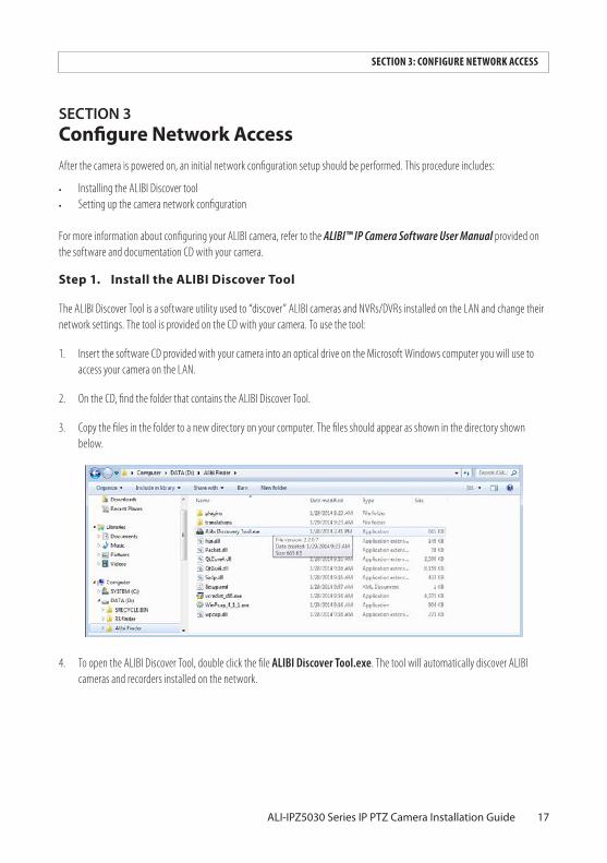
3. Copy the files in the folder to a new directory on your computer. The files should appear as shown in the directory shown below.
4. To open the ALIBI Discover Tool, double click the file ALIBI Discover Tool.exe. The tool will automatically discover ALIBI cameras and recorders installed on the network.
SECTION 3: CONFIGURE NETWORK ACCESS

18
5. To change the network settings of the camera to be compatible with the subnet where it is installed, do the following:
a. Click the device to highlight it. Notice that the network parameters are shown in the right frame.
SECTION 3: CONFIGURE NETWORK ACCESS

19ALI-IPZ5030 Series IP PTZ Camera Installation Guide
b. Modify the network settings to values compatible with the subnet where it is installed.
c. Enter the admin password for the device in the password field. By default, the admin user password for ALIBI cameras is 1111.
d. Click the Save button. The new IP address, port, etc. settings will appear in the list with the device you modified.
6. Close the ALIBI Discover Tool by clicking the Close icon ( T ) in the upper-right corner of the screen.
SECTION 3: CONFIGURE NETWORK ACCESS

20
SECTION4 Remote loginTo access the camera from a computer on the LAN:
1. Open your Microsoft Internet Explorer browser on your compute and enter the IP address of the camera in the URL field. In the example below, the IP address of the camera is 192.168.75.18.
2. In the login window, enter your User Name and Password in the appropriate fields, then click Login. The default User Name and Password for ALIBI cameras is admin and 1111.
3. If this is the first time you are logging into the camera at this IP address AND you are using Internet Explorer 10 or newer, you must configure IE for Compatibility mode:
a. In Internet Explorer, click the Tools icon (located to the right of the tabs), then select Compatibility View settings from the drop-down menu.
SECTION 4: REMOTE LOGIN

21ALI-IPZ5030 Series IP PTZ Camera Installation Guide
Tools icon
b. In the Compatibility View Settings window, ensure that the IP address of your camera is in the Add this website field, then click Add.
c. After clicking Add, the IP address will appear in the Websites list. Click Close.
d. If a message on the screen requesting that you install a plug-in (see below), click on the message and continue with the following sub-steps. A message box will appear at the bottom of the window to install the WebComponents plug-in.
SECTION 4: REMOTE LOGIN

22
Otherwise, continue with step “4. In the Live View window shown below, click the PTZ button to open/close the PTZ control panel.” on page 23.
e. In the message box, click Run to install WebComponents.exe. The following pop-up window will open. When this window appears, close the browser.
f. Click Next to install WebComponents. Allow the plug-in installation to complete. When the following window appears, click Finish.
SECTION 4: REMOTE LOGIN

23ALI-IPZ5030 Series IP PTZ Camera Installation Guide
g. Log into the camera again. A Live View display will appear.
4. In the Live View window shown below, click the PTZ button to open/close the PTZ control panel.
SECTION 4: REMOTE LOGIN

24
PTZ button PTZ control panelPTZ manual controls
5. In the PTZ control panel, click the manual control arrows to exercise the pan-tilt-zoom features of the camera.
4.1 Additional configuration steps
Refer to the document ALIBI™ IP Camera Software User Manual provided on the software and documentation CD with your camera to customize the configuration of your camera.
SECTION 4: REMOTE LOGIN

25ALI-IPZ5030 Series IP PTZ Camera Installation Guide
APPENDIXA Specifications
Product Specifications ALI-IPZ5030T ALI-IPZ5030RT
Camera
Image Sensor 1/2.8” CMOS
Scanning Mode Progressive Scan
Resolution Up to 1920 x 1080
Effective Pixels Approx. 2.1 Megapixel
Minimum Illumination Color: 0.05 Lux (F1.6, AGC On) B/W: 0.005 Lux (F1.6, AGC On)
Color: 0.05 Lux (F1.6, AGC On) B/W: 0 Lux (IR ON)
Day/Night True Day/Night ICR)
Wide Dynamic Range DWDR
Electronic Shutter (sec) 1 ~ 1/30000
Gain Control Auto/Manual
White Balance Mode Auto/Manual/ATW/Indoor/Outdoor/Daylight Lamp/Sodium Lamp
Noise Reduction 3D DNR
IR Illuminators N/A Smart IR Array, 850 nm
IR Array Range N/A 390 ft
IR Sensitivity 700 - 1100 nm
Panning Range and Speed 0° ~ 360°, Max 160°/Sec
Tilting Range and Speed -2° ~ 90°, Max 120°/Sec
Lens
Lens Type Varifocal
Focal Length 4.3 ~ 129 mm
Iris Auto
Focus Auto/Semiautomatic/Manual
Horizontal Viewing Angle 57.4° (Wide) ~ 2.8° (Tele)
F-number F1.6 ~ F5.0
Video
Video Compression Format H.264 (Baseline/Main/High Profile), MPEG-4, MJPEG
Codec Streaming Capability Tri Streaming
Maximum Frame Rate 30fps @ 1080p
Bit Rate 32 kbps ~ 16 Mbps
Bit Rate Mode CBR, VBR
APPENDIX A: SPECIFICATIONS

26
Product Specifications ALI-IPZ5030T ALI-IPZ5030RT
Audio
Audio Streaming Two-way
Audio Compression Format G.711u /G.711a /G.726
Pan and Tilt
Smart Tracking Yes
Number of Presets 256
Patrol 8 Patrols, Up to 32 presets per patrol
Pattern 4 Patterns
PTZ Position Display On/Off
Features
Motion Detection Yes
Event Notification Alarm Output, Email, FTP
Privacy Mask Yes
ROI Encoding Up to 24 areas with adjustable levels
Defog Yes
Video Analytics Tamper Detection
Interface
Ethernet RJ-45 10/100 BASE-T
Audio Input 1x In
Audio Output 1x Out
Sensor Input 7x In
Alarm Ouput 2x Out
SD Card Slot 1x SD/SDHC (up to 32GB)
Video Output 1x BNC
Network
Protocols IPv4/IPv6, HTTP, HTTPS, 802.1x, Qos, FTP, SMTP, UPnP, SNMP, DNS, DDNS, NTP, RTSP, RTP, TCP, UDP, IGMP, ICMP, DHCP, PPPoE, ONVIF, PSIA
Security Password Protection
Number of Connections Up to 10
General
Power Requirements High-PoE / 24 Vac
Power Consumption High-PoE: Max. 20 W (Heater Off) / Max. 40 W (Heater On) 24 Vac: Max. 20 W (Heater Off) / Max. 65 W (Heater On)
High-PoE: Max. 30 W (Heater Off) / Max. 50 W (Heater On) 24 Vac: Max. 20 W (Heater Off) / Max. 65 W (Heater On)
Weight 11.02 lbs. 12.13 lbs.
APPENDIX A: SPECIFICATIONS

27ALI-IPZ5030 Series IP PTZ Camera Installation Guide
Product Specifications ALI-IPZ5030T ALI-IPZ5030RT
Dimensions 12.02” H x 8.66” Φ 15.71” H x 9.65” Φ
Operating Temperature High-PoE: -22°F ~ 149°F 24 Vac: -40°F ~ 149°F
Operating Humidity 0% ~ 90% RH, Non-condensing
Ingress Protection IP66
Color Beige
Material Aluminum (Body) / Polycarbonate (Bubble)
Approvals CE, FCC, RoHS
System Requirements
Operating System Windows XP Professional, Windows VISTA, Windows 7, Window 8
Processor Intel Pentium 4 3.0 GHz or later
Memory 1 GB or above RAM
Display 1024 x 768 resolution or higher
Web Browser Internet Explorer 7.0 or above, Apple Safari 5.02 or above, Mozilla Firefox 3.5 or above, Google Chrome 8 or above
Internet Explorer 6.0 or above, Apple Safari 5.02 or above, Mozilla Firefox 3.5 or above, Google Chrome 8 or above
Supplied Accessories
CD ROM (Software User Manual, Installation Tools), Installation Guide, HPoE Midspan Injector, Installation Hardware
APPENDIX A: SPECIFICATIONS

28
APPENDIXB Lightning and Surge ProtectionThis product includes TVS plate lightning protection technology to prevent damage caused by a pulse signal that is below 3000 watts from sources such as lighting, surging, etc. Protection measures must be taken to ensure electrical safety.
• The distance between signal transmission line and high-voltage equipment or high-voltage cable is at least 50 m.• Outdoor wiring should better be along the eaves as much as possible.• In the open field, wiring should be buried underground in sealed steel pipe with one-point grounding. Overhead routing
method is not acceptable.• In regions with thunderstorms or where high induction voltage are present (such as high-voltage transformer substation),
high power lightning protection apparatus and lightning conductor are necessary. • The design for installation and wiring with lightning protection and grounding should be combined with the lightning
protection consideration of the building, and conform to the relevant national and industry standards.• The system should ensure equi-potential grounding. Grounding equipment must satisfy both system anti-jamming and
electric safety. It must not allow short circuit and open circuit with the zero conductor of strong grid. When the system is singularly ground, the resistance must less than 4 Ω and the cross-sectional area of the grounding cable must be no less than 25 mm2. For grounding instructions, refer to local electrical codes and this manual.
Lightening rodCommunicate arrester
Video arrester
Power arrester45° conical envelope
The resistance of earthing conductor
must be less than 4 Ω.
The camera should be within a 45° envelope under the lightening rod.
Steel jacket
Lightning & Surge Protection
APPENDIX B: LIGHTENING AND SURGE PROTECTION

29ALI-IPZ5030 Series IP PTZ Camera Installation Guide
APPENDIXC 24 Vac Wire Gauge and Transmission DistanceThe following table shows the recommended maximum distance adopted for the different wire sizes when the 24 Vac voltage loss is less than 10%. For the AC driven device, the maximum voltage loss rate allowable is 10%. For example, for a device with the rating power of 80 VA which is installed 35 feet (10 m) from the transformer, the minimum wire gauge required is 0.8000 mm.
Table1.Tableofwiregaugestandards
Distance: ft (m) Wire Gauge (mm)
Power (VA) 0.8000 1.000 1.250 2.000
10 283 (86) 451 (137) 716 (218) 1811 (551)
20 141 (42) 225 (68) 358 (109) 905 (275)
30 94 (28) 150 (45) 238 (72) 603 (183)
40 70 (21) 112 (34) 179 (54) 452 (137)
50 56 (17) 90 (27) 143 (43) 362 (110)
60 47 (14) 75 (22) 119 (36) 301 (91)
70 40 (12) 64 (19) 102 (31) 258 (78)
80 35 (10) 56 (17) 89 (27) 226 (68)
90 31 (9) 50 (15) 79 (24) 201 (61)
100 28 (8) 45 (13) 71 (21) 181 (55)
110 25 (7) 41 (12) 65 (19) 164 (49)
120 23 (7) 37 (11) 59 (17) 150 (45)
130 21 (6) 34 (10) 55 (16) 139 (42)
140 20 (6) 32 (9) 51 (15) 129 (39)
150 18 (5) 30 (9) 47 (14) 120 (36)
160 17 (5) 28 (8) 44 (13) 113 (34)
170 16 (4) 26 (7) 42 (12) 106 (32)
180 15 (4) 25 (7) 39 (11) 100 (30)
190 14 (4) 23 (7) 37 (11) 95 (28)
200 14 (4) 22 (6) 35 (10) 90 (27)
APPENDIX C: 24 VAC WIRE GAUGE AND TRANSMISSION DISTANCE

30
Table2.WireGaugeStandards
Bare Wire Gauge (mm) American Wire Gauge AWG
Cross-sectional Area of Bare Wire (mm2)
0.750 21 0.4417
0.800 20 0.5027
0.900 19 0.6362
1.000 18 0.7854
1.250 16 1.2266
1.500 15 1.7663
2.000 12 3.1420
2.500 4.9080
3.000 7.0683
APPENDIX C: 24 VAC WIRE GAUGE AND TRANSMISSION DISTANCE