akita national college of technology work …akita-nct.jp/~kobay/fes.pdf · akita national college...
TRANSCRIPT
AKITA NATIONAL COLLEGE OF TECHNOLOGY
WORK PLACEMENT PROJECT
FES- CYCLING UNIT RESEARCH AND REDESIGN
1.4.-11.6.2012
____________________
LASSE KETONEN
2
Akita National College of Technology
Heartfelt thanks My work placement would not been possible with several people which I like to thank for successful project. Thanks of having this opportunity to have work placement in Akita National College of Technology goes to School President Mr. Muneyoshi Yamada, Mr. Sugawara, Mr. Kobayashi and mechanical engineering department. I would also like to thank Ms. Harumi Ito from great Japanese lectures and endless smiling which cheers everybody up. I want to thank also my working group of good working spirit and effort to project. Especially Mr. Kobayashi to always inspire he`s students and for he`s effort to this FES- project over three year period. He was very interest about this project and also inspire group to new innovations and better results. I also like to thank Siti Radziah Yusoff to she`s endless help of Japanese translations and communication skills. She was always thinking creatively and positively even when there was stress about other projects and exams. I wish you all keep your attitude to be interested about new things and positively thinking rest of your life. It was really honor to work with you. I would like thank also my friends and especially to other internship students for great times in Japan. Thanks Hanif and Takuta for helping in everyday problems and being good friends of mine, French students Clement, Kevin, Christophe and Lionel for funny moments, Mo from good spirit and Martti for be the only guy to speak my mother tongue. From these friends I got much understanding about different cultures and ways of living and also everlasting memories. And for last I want to thank Mr. Kurogi and all rugby team members from good team spirit and good trainings.
3
Akita National College of Technology
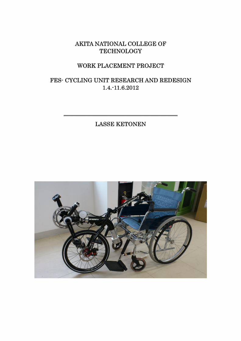
Abstract My work placement task was research FES- (Functional electrical stimulation) cycling and design new cycling unit. FES- cycling is a therapy treatment to spinal cord injury (SCI) patients. FES- cycling has proved to improve SCI- patient healthy and quality of life. Akita National College of technology (Akita NCT) has researched FES- cycling with Akita University three years. Akita University has researched health benefits of FES- cycling and Akita NCT has researched removable FES- cycling units. My task was to develop FES- unit 1 which was made using commercial parts in Akita NCT. Working group included Mr. Kobayashi, me, Siti Radziah Yusoff, Himori Koosei, Abukawa Yoshiyaki and Takahashi Shoohei. In this group we redesigned FES- unit 1 parts and manufactured them as much as possible before I left back to Finland 11.6.2012. Designing process included researching of FES- cycling from medical journeys, researching and solving problems of old FES- cycling unit 1 and developing and designing now FES- unit. Manufacturing process included designing of machinery, mechanical drawings, part list, material purchase and machining processes. My task was also wrote report to Turku University and Akita NCT from this project.
4
Akita National College of Technology
Contents
1. Spinal cord injury and FES- cycling 5 1.1 Spinal cord injury (SCI) 5 1.2 FES (Functional electrical stimulation)- cycling 5 1.3 Functional electrical stimulation 6 1.4 Health benefits of FES- cycling 8
2. Akita NCT FES- project 10
2.1 FES- research in Akita NCT and Akita University 10 2.2 Cycling Units 10 2.3 Work placement project: Research and Develop FES- Unit 1 11
3. Design process 14 3.1Problem solving 14 3.2 Redesign 16
4. Manufacturing parts 21
4.1 Akita NCT workshop 21 4.2 Manufacturing parts 22
Summary 24 Appendix 25 Technical drawings My Japan experience Accomplishment report
5
Akita National College of Technology
1. Spinal cord injury and FES- cycling
1.1 Spinal Cord Injury
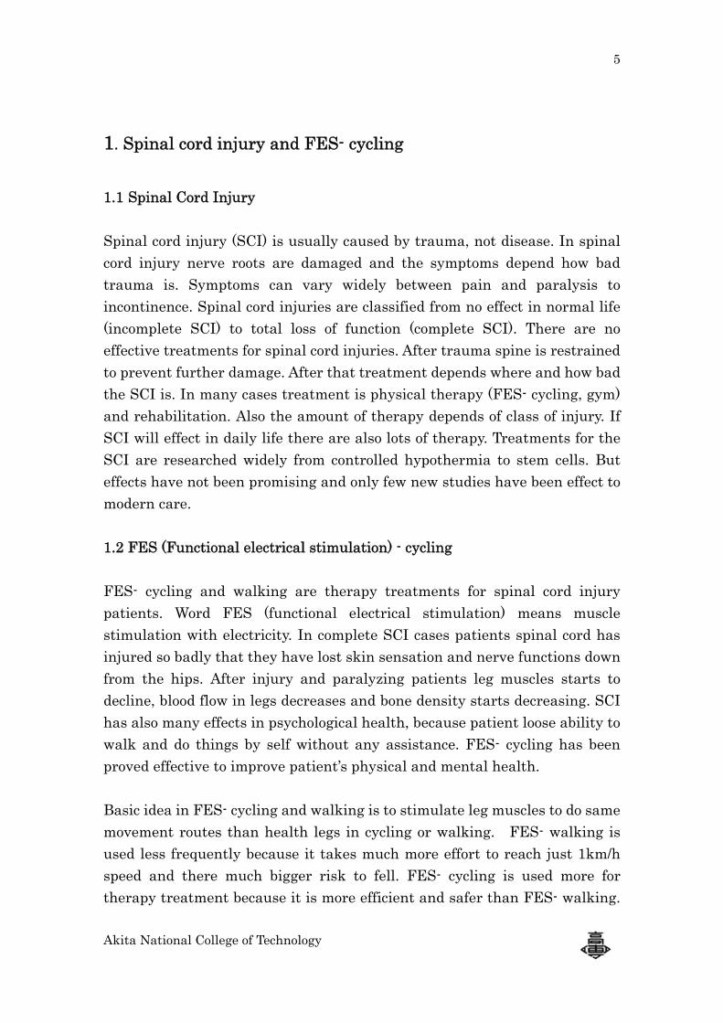
Spinal cord injury (SCI) is usually caused by trauma, not disease. In spinal cord injury nerve roots are damaged and the symptoms depend how bad trauma is. Symptoms can vary widely between pain and paralysis to incontinence. Spinal cord injuries are classified from no effect in normal life (incomplete SCI) to total loss of function (complete SCI). There are no effective treatments for spinal cord injuries. After trauma spine is restrained to prevent further damage. After that treatment depends where and how bad the SCI is. In many cases treatment is physical therapy (FES- cycling, gym) and rehabilitation. Also the amount of therapy depends of class of injury. If SCI will effect in daily life there are also lots of therapy. Treatments for the SCI are researched widely from controlled hypothermia to stem cells. But effects have not been promising and only few new studies have been effect to modern care. 1.2 FES (Functional electrical stimulation) - cycling FES- cycling and walking are therapy treatments for spinal cord injury patients. Word FES (functional electrical stimulation) means muscle stimulation with electricity. In complete SCI cases patients spinal cord has injured so badly that they have lost skin sensation and nerve functions down from the hips. After injury and paralyzing patients leg muscles starts to decline, blood flow in legs decreases and bone density starts decreasing. SCI has also many effects in psychological health, because patient loose ability to walk and do things by self without any assistance. FES- cycling has been proved effective to improve patient’s physical and mental health. Basic idea in FES- cycling and walking is to stimulate leg muscles to do same movement routes than health legs in cycling or walking. FES- walking is used less frequently because it takes much more effort to reach just 1km/h speed and there much bigger risk to fell. FES- cycling is used more for therapy treatment because it is more efficient and safer than FES- walking.
Akita
CyclBecaMospati 1.3 F
In cyglutbendelectspinmesnervstimmakordediffiIt beFESposistim
Figur
a National
ling is alsause of thast of theraent home.
Functiona
ycling leg eal muscld legs. Mutrical mes
nal cord insages to le
ve messagmulation iske a cyclinger, time ancult musclend and st
S- cycles htion data
mulates m
re 1. FES- c
College of T
so more efat there isapy is stil
al electrica
muscles dles and causcle stimssages fromnjury patieeg musclesge cannot s executedg movemend power.le to stimutraight kn
have angleand pati
muscles.
cycling test
Technology
fficient was a way thall done wi
al stimulat
o work to alf musclesulation anm brain thents spinas. This me
reach it.d by surfaent every n. This rhulate is hanee and exe encoder tent anatoIn one 3
in Akita Un
ay of tranat patient ith station
tion
move cycles do worknd movemhrough spial cord is deans that u Because ace electroneeded muhythm depamstring, bxtends hipto measur
omy based360 degre
niversity
nsportationcan move
nary FES
e cranks. Qk in certai
ment track inal cord tdamaged susually leg
of that iodes or im
uscle mustpends of pbecause it
ps in total re the crand stimulate round
n comparee by self wiS- cycles in
Quadricepin order to
of legs arto leg musso it can ng nerves ain FES- cmplanted be stimul
patient’s ais biarticudifferent pnk positiotion patterevery mu
ed to walkith FES- cn hospita
ps, hamstro straightre executescles.. Becnot send nare healthycycling muelectrodes
lated in coanatomy. Mulaire musperiods. E
on. With crn, stimuuscle has
6
king. cycle. ls or
ings, t and ed by cause nerve y but uscle s. To rrect Most scles.
Every rank lator
one
7
Akita National College of Technology
stimulation process. Muscle stimulation order in FES- cycling is (right pedal straight forward, crank rotating anti clockwise) left quadriceps, left hamstrings, right quadriceps, right hamstrings, left gluteus and right gluteus. The stimulation is done by stimulator and surface electrodes or implanted electrodes. Surface electrodes are easier to attach and remove but they need lot of current because weakened skin sensation and to reach big lower extremity muscles. Because high currents, using the surface electrodes feels like needles stinging the skin. The contraction of the muscle feels like cramp so it is less painful. Using larger surface electrodes the density of current (mA/cm2) can be lowered. That improves tolerability of treatment. Implanted electrodes do not have problem of poor skin sensation and reaching lower muscles, but they need a surgery. There also possibility to use smaller, injectable stimulation unit BION. Each BION is attached near nerve and they are controlled outside of the body with controller. This method allows also easier stimulation of lower muscles like Iliopsoas, which flexes hips. The BION is best way to stimulate muscles because it’s small size, efficiency of stimulating lower muscles and small size of attachment surgery. Only downside of BION is the prize. FES- cycling needs minimum 6 BION`s and that would be really expensive method.
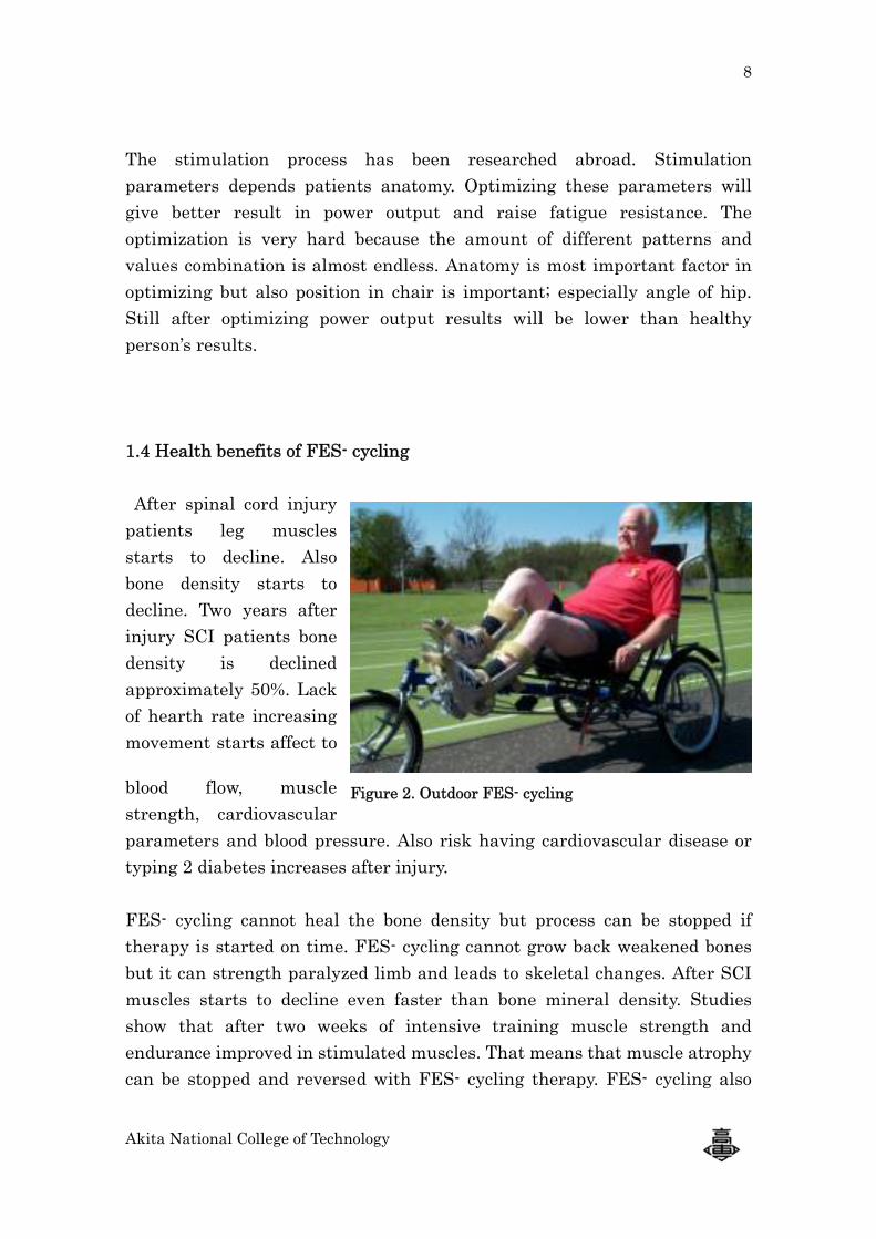
Table 1. FES- Parameters
FES-
parameters
PARAMETER RANGE COMMON
Frequency 20-60 Hz 30 Hz
Max. Current 120-300 mA 150 mA
Pulse duration 0.1-1 ms 0.4 ms
Pulse form Block, sinus, triangel Block
Polarity Mono- biphasic Biphasic
Pulse train Ramp up, ramp down, initial doublet Ramp up
Timing Start- stop moment every muscle
Pre set 100-150 ms 125 ms
8
Akita National College of Technology
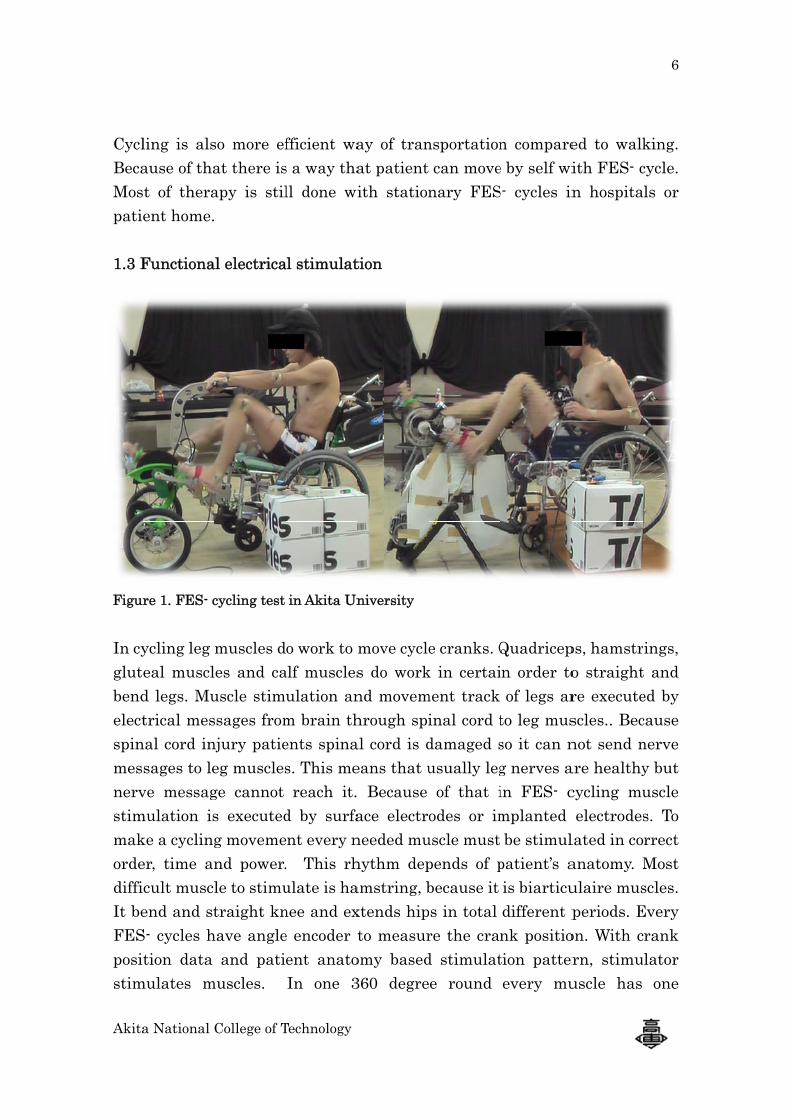
The stimulation process has been researched abroad. Stimulation parameters depends patients anatomy. Optimizing these parameters will give better result in power output and raise fatigue resistance. The optimization is very hard because the amount of different patterns and values combination is almost endless. Anatomy is most important factor in optimizing but also position in chair is important; especially angle of hip. Still after optimizing power output results will be lower than healthy person’s results. 1.4 Health benefits of FES- cycling After spinal cord injury patients leg muscles starts to decline. Also bone density starts to decline. Two years after injury SCI patients bone density is declined approximately 50%. Lack of hearth rate increasing movement starts affect to
blood flow, muscle strength, cardiovascular parameters and blood pressure. Also risk having cardiovascular disease or typing 2 diabetes increases after injury. FES- cycling cannot heal the bone density but process can be stopped if therapy is started on time. FES- cycling cannot grow back weakened bones but it can strength paralyzed limb and leads to skeletal changes. After SCI muscles starts to decline even faster than bone mineral density. Studies show that after two weeks of intensive training muscle strength and endurance improved in stimulated muscles. That means that muscle atrophy can be stopped and reversed with FES- cycling therapy. FES- cycling also
Figure 2. Outdoor FES- cycling
9
Akita National College of Technology
improves motion range in hips and lower back which improves patient ability to survive in daily activities. FES- cycling has same effects than regular sports to patient. It improves cardiovascular parameters and arterial inflow. It also effect positively to metabolic and cardiopulmonary responses which shown as better oxygen delivery in muscles and better removal of metabolic end products. An endurance and power level indicates which means longer training with higher power output. It increases heart rate, stroke volume, cardiac output, blood pressure and pulmonary ventilation. Strengthen muscles can be also seen as valuable tissue which works like cushion protecting bones and body. Paralyzing leads to muscle decline, because muscles cannot work without nerve messages. This means weakened blood flow in tissue. Because limb paralyzing and weakened muscles and blood flow, SCI patient usually have pressure sores. Pressure sores are demoralizing and can take several months to heal involving long stay in bed. FES- cycling has been proven reduce the incidence of pressure sores very effectively. FES- cycling also has mental benefits. Patients healthy and fitness improves which improves self-image. Due the training body releases beta- endorphin which gives person a good feeling. Also better flexibility and fitness helps patient to survive in daily life better. FES- cycling has been studied over 30 years. Their health benefit to spinal cord injury patient health has been proven by many studies. FES- cycling is much more practical than FES- walking because its better power output and safeness. But on the other hand FES- walking has strong mental effects, because patient can walk after paralyzing. One of the best things in FES- cycling is the easy and safe usability. Patient can use stationary cycle in home by self. Despite the health benefits of FES- cycling, not so many SCI-patient use FES- cycle as therapy treatment. In year 2008 there was four companies which are involved in FES- cycling. Three of those are selling products. Most of products are stationary cycles. Two of the companies produce cycles to outdoor use and only one produce removable FES- cycling unit to wheelchair.
Akita
2. A 2.1 F
Akitcyclieffec(Akiare t
Univof Rdoesunitoutd 2.2 CFirsframand part27.227.5connin th
Figu
a National
Akita NC
FES- resea
ta Universing approxcts of FESita NCT) hthree diffe
versity anRemovable sn’t need gt to wheelcdoor use an
Cycling Unt cycling u
me is fromaluminum
t which is 2mm pipes5mm hole nection is hree differ
ure 3. FES-
College of T
T FES- p
arch in Ak
sity and Akximately 3S- cycling has researerent versi
nd two remFES- cycl
get off fromchair and nd moving
nits unit in Ak
m recumbenm pipe fraattached t
s. In the enwhere thapproxim
rent angles
unit 1
Technology
project
kita NCT a
kita Natio3 years. Ak
in laborarched attaions of FE
movable FEling unit im wheelchattach sti
g with FES
kita NCT int cycle aname. Attato wheelchnd of cyclinhe T-part ately 150ms by chang
and Akita
onal Collegkita Univetory. Akitachable FE
ES- cycles i
ES- cyclingis to makehair to starimulation S are impo
is made bnd include
achment tohairs frontng unit is ais attache
mm aboveging angle
Fig
Universit
ge of Technersity has ra NationaES- cyclinin Akita; T
g unit verse cycling ert cycling. pads and
ortant valu
based on ces 9 gearso wheelcht pipes. T-a bushing.ed with tie floor. Seae of the T-p
gure 4. FES
y
nology hasresearchedal College ng to wheeTricycle ve
sions in Akasier to paPatient justart FES
ues to rese
ommercias, disk brahair is exe
part is we. In the enightening at angle capart. Leng
- unit 3
s studied Fd physioloof Techno
el chair. Tersion in A
kita NCT. atient. Paust add cyS-therapy. earch.
al product.ake, handlecuted witelded from
nd of bushiscrew. Ac
an be adjugth adjustm
10
FES- ogical ology
There Akita
Idea tient cling Also
The lebar th T-
m two ing is ctual usted ment
11
Akita National College of Technology
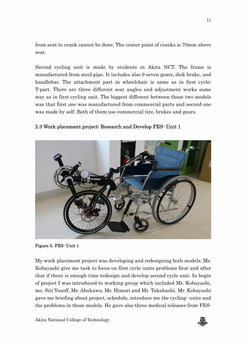
from seat to crank cannot be done. The center point of cranks is 70mm above seat. Second cycling unit is made by students in Akita NCT. The frame is manufactured from steel pipe. It includes also 9 seven gears, disk brake, and handlebar. The attachment part in wheelchair is same as in first cycle; T-part. There are three different seat angles and adjustment works same way as in first cycling unit. The biggest different between these two models was that first one was manufactured from commercial parts and second one was made by self. Both of them use commercial tire, brakes and gears. 2.3 Work placement project: Research and Develop FES- Unit 1
Figure 5. FES- Unit 1 My work placement project was developing and redesigning both models. Mr. Kobayashi give me task to focus on first cycle units problems first and after that if there is enough time redesign and develop second cycle unit. In begin of project I was introduced to working group which included Mr. Kobayashi, me, Siti Yusoff, Mr. Abukawa, Mr. Himori and Mr. Takahashi. Mr. Kobayashi gave me briefing about project, schedule, introduce me the cycling- units and the problems in those models. He gave also three medical releases from FES-
12
Akita National College of Technology
cycling, spinal cord injury therapy treatments and already made FES- cycling units and models. Mr. Kobayashi has also an idea to made force sensor by self during work emplacement, but the schedule was too tight to make force sensor and both design and manufacture parts to FES- unit. 1st schedule of the work emplacement in Akita NCT in FES- project
April 13th Studying medical releases and FES- cycling April 16th – May 18th Redesigning and manufacturing parts May 21- May 31 Bump test and acceleration (z-y-z) measure June 1st Report making
2.4 Problems in old FES- units FES-unit 1 FES-unit 2
Structure OK (according to use commercial product)
Weak → need to
improve Connect & Release (wheel chair and cycling unit)
It takes about 1-2 minutes (normal people) → need to improve
Difficult ( Have to use tools) → need to improve
Weight Ok Heavy (steel frame) →need to improve
Safety Low → need to improve
Low → need to improve
Changing seat angle and B.B position
A little difficult →
need to improve Easy → need to improve
Table 2. Problems in FES- unit 1 (Commercial parts) and FES- unit 2 (manufactured in Akita NCT) given by Mr. Kobayashi in project briefing.
13
Akita National College of Technology
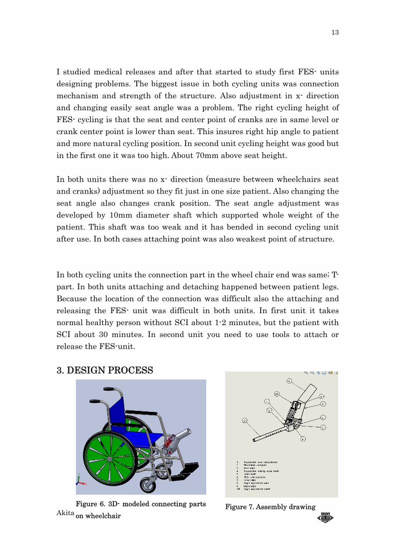
I studied medical releases and after that started to study first FES- units designing problems. The biggest issue in both cycling units was connection mechanism and strength of the structure. Also adjustment in x- direction and changing easily seat angle was a problem. The right cycling height of FES- cycling is that the seat and center point of cranks are in same level or crank center point is lower than seat. This insures right hip angle to patient and more natural cycling position. In second unit cycling height was good but in the first one it was too high. About 70mm above seat height. In both units there was no x- direction (measure between wheelchairs seat and cranks) adjustment so they fit just in one size patient. Also changing the seat angle also changes crank position. The seat angle adjustment was developed by 10mm diameter shaft which supported whole weight of the patient. This shaft was too weak and it has bended in second cycling unit after use. In both cases attaching point was also weakest point of structure. In both cycling units the connection part in the wheel chair end was same; T- part. In both units attaching and detaching happened between patient legs. Because the location of the connection was difficult also the attaching and releasing the FES- unit was difficult in both units. In first unit it takes normal healthy person without SCI about 1-2 minutes, but the patient with SCI about 30 minutes. In second unit you need to use tools to attach or release the FES-unit. 3. DESIGN PROCESS
Figure 6. 3D- modeled connecting partson wheelchair
Figure 7. Assembly drawing
14
Akita National College of Technology
3.1 Problem solving
We started design process of FES- unit one by solving the problems about attaching and adjusting the FES- unit. Table 3. Problems in FES- unit 1 and resolves Problem Resolve Structure Cycling unit structure
is good (Commercial product)
OK
Connect and Release Connection action happens between legs about 15 centimeters from ground, take much time and is difficult
Redesign connection parts in wheelchair and cycling unit
Weight Parts too heavy Change materials to aluminum and use more thinner material strength
Safety Cyclers weight is carried by one 10mm diameter aluminum shaft
Redesign connection parts. Use bigger diameter shafts and design unit way that weight divides to several parts
Adjustment Seat angle adjustment changes also cycling height. No x- direction adjustment.
Design adjustment system which changes only seat angle and which can adjust x- direction too.
Vibrations, shaking In outdoor cycle cycling unit makes vibrations to wheelchair and patient. That can cause dizziness and nausea in patient
Add suspension in cycling unit
15
Akita National College of Technology
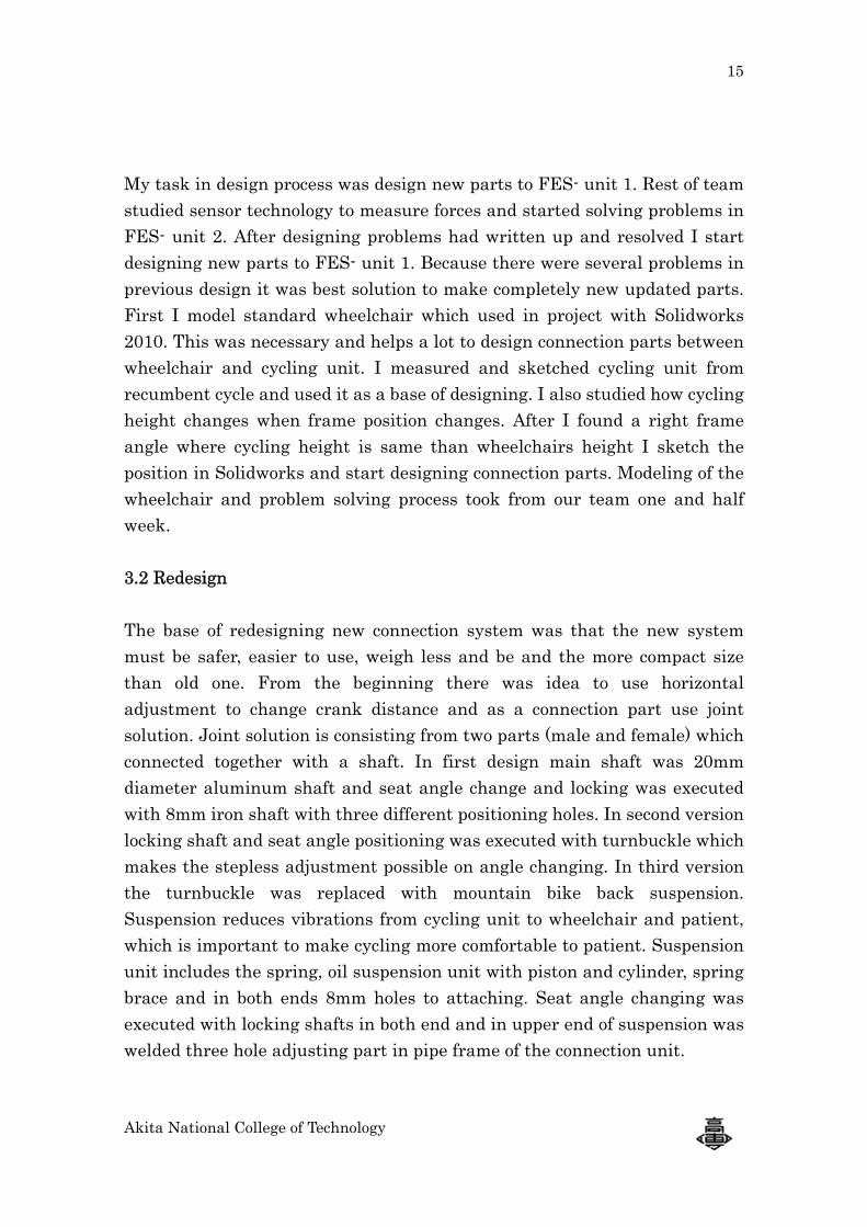
My task in design process was design new parts to FES- unit 1. Rest of team studied sensor technology to measure forces and started solving problems in FES- unit 2. After designing problems had written up and resolved I start designing new parts to FES- unit 1. Because there were several problems in previous design it was best solution to make completely new updated parts. First I model standard wheelchair which used in project with Solidworks 2010. This was necessary and helps a lot to design connection parts between wheelchair and cycling unit. I measured and sketched cycling unit from recumbent cycle and used it as a base of designing. I also studied how cycling height changes when frame position changes. After I found a right frame angle where cycling height is same than wheelchairs height I sketch the position in Solidworks and start designing connection parts. Modeling of the wheelchair and problem solving process took from our team one and half week. 3.2 Redesign The base of redesigning new connection system was that the new system must be safer, easier to use, weigh less and be and the more compact size than old one. From the beginning there was idea to use horizontal adjustment to change crank distance and as a connection part use joint solution. Joint solution is consisting from two parts (male and female) which connected together with a shaft. In first design main shaft was 20mm diameter aluminum shaft and seat angle change and locking was executed with 8mm iron shaft with three different positioning holes. In second version locking shaft and seat angle positioning was executed with turnbuckle which makes the stepless adjustment possible on angle changing. In third version the turnbuckle was replaced with mountain bike back suspension. Suspension reduces vibrations from cycling unit to wheelchair and patient, which is important to make cycling more comfortable to patient. Suspension unit includes the spring, oil suspension unit with piston and cylinder, spring brace and in both ends 8mm holes to attaching. Seat angle changing was executed with locking shafts in both end and in upper end of suspension was welded three hole adjusting part in pipe frame of the connection unit.
16
Akita National College of Technology
We decided use the suspension solution in the connection unit, because it makes seat angle changing easy, reduce vibration to the wheelchair and patient and it is safer with 20mm aluminum shaft and 8mm steel locking shafts. Also the connection happens higher and it is much easier place than is original version. Patient needs attach only two pins in good ergonomic location and cycling unit is attached. All shafts were
secured with R- pins to improve safeness of biking. The length adjustment between cranks and seat was executed with inner and outer pipe. Outer pipes diameter is 27.2 and inner diameter 21.6. Inner pipes diameter is 21.7 and inner 16.2. In inner pipe there are five millimeter holes 20mm distance from each other and in outer pipe there is two five millimeter holes 60mm from each other. In holes there are two 5mm locking shafts. In the end of inner pipe the male piece of joint unit is attached with M8 lock bolt. Outer pipe is attached in wheelchairs body with two 21.6 crossbars. Connection between outer pipe and crossbars is executed with two connection parts. These aluminum parts includes two one upon the other crossing holes for inner and outer pipe diameters and M5 tightening bolts. Crossbars are attached in wheelchairs vertical pipes with commercial connection parts ordered from MISUMI. These parts are designed to connect to 20mm diameter pipes together in various angles.
Figure 8. Suspension unit
Figure 9. Misumi FLYC 20-20
HC-0-31
17
Akita National College of Technology
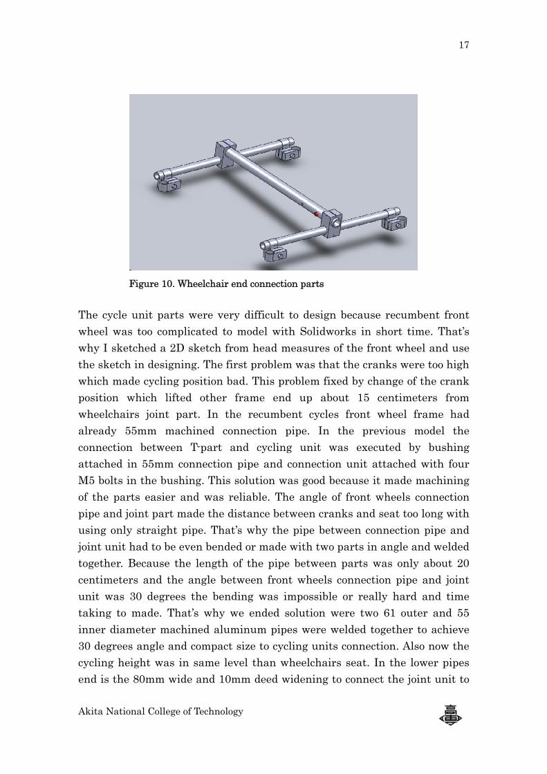
The cycle unit parts were very difficult to design because recumbent front wheel was too complicated to model with Solidworks in short time. That’s why I sketched a 2D sketch from head measures of the front wheel and use the sketch in designing. The first problem was that the cranks were too high which made cycling position bad. This problem fixed by change of the crank position which lifted other frame end up about 15 centimeters from wheelchairs joint part. In the recumbent cycles front wheel frame had already 55mm machined connection pipe. In the previous model the connection between T-part and cycling unit was executed by bushing attached in 55mm connection pipe and connection unit attached with four M5 bolts in the bushing. This solution was good because it made machining of the parts easier and was reliable. The angle of front wheels connection pipe and joint part made the distance between cranks and seat too long with using only straight pipe. That’s why the pipe between connection pipe and joint unit had to be even bended or made with two parts in angle and welded together. Because the length of the pipe between parts was only about 20 centimeters and the angle between front wheels connection pipe and joint unit was 30 degrees the bending was impossible or really hard and time taking to made. That’s why we ended solution were two 61 outer and 55 inner diameter machined aluminum pipes were welded together to achieve 30 degrees angle and compact size to cycling units connection. Also now the cycling height was in same level than wheelchairs seat. In the lower pipes end is the 80mm wide and 10mm deed widening to connect the joint unit to
Figure 10. Wheelchair end connection parts
18
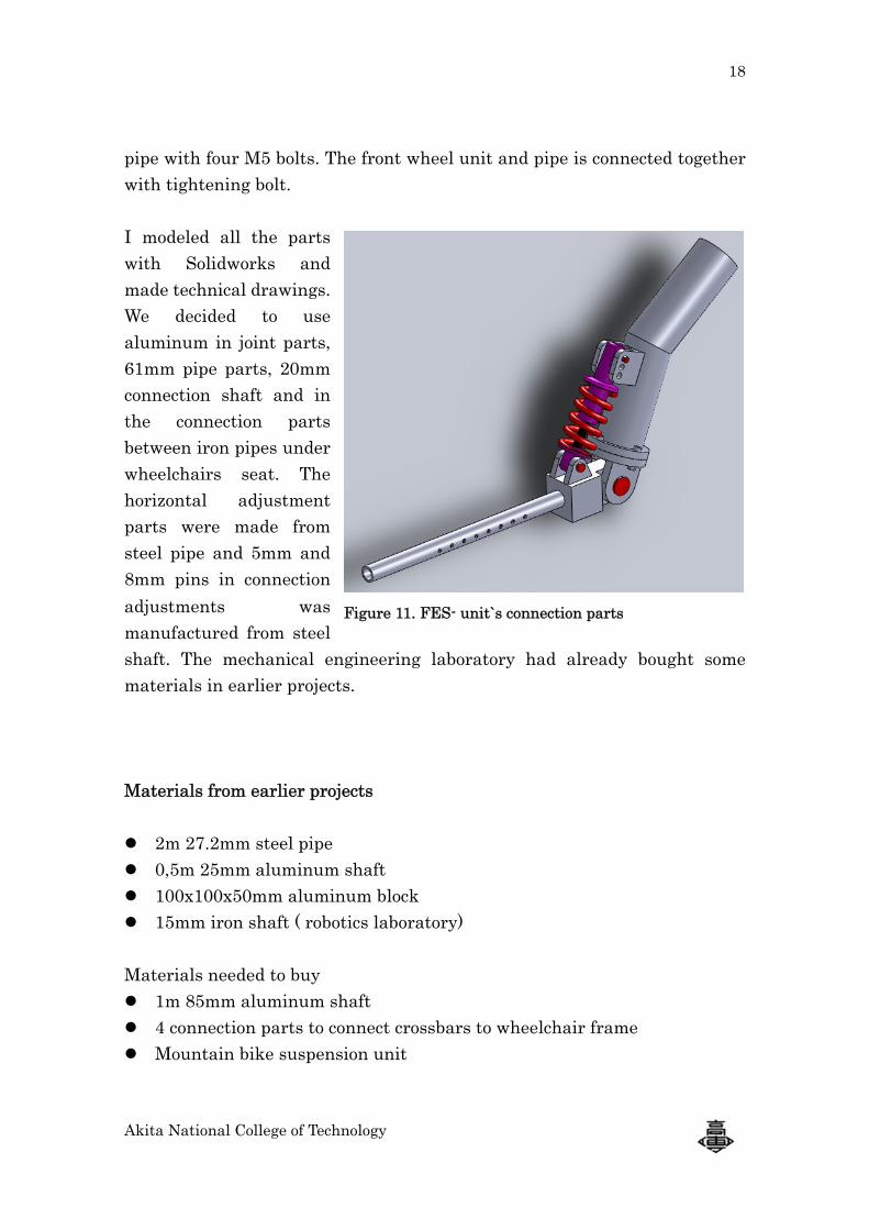
Akita National College of Technology
pipe with four M5 bolts. The front wheel unit and pipe is connected together with tightening bolt. I modeled all the parts with Solidworks and made technical drawings. We decided to use aluminum in joint parts, 61mm pipe parts, 20mm connection shaft and in the connection parts between iron pipes under wheelchairs seat. The horizontal adjustment parts were made from steel pipe and 5mm and 8mm pins in connection adjustments was manufactured from steel shaft. The mechanical engineering laboratory had already bought some materials in earlier projects. Materials from earlier projects
2m 27.2mm steel pipe 0,5m 25mm aluminum shaft 100x100x50mm aluminum block 15mm iron shaft ( robotics laboratory)
Materials needed to buy
1m 85mm aluminum shaft 4 connection parts to connect crossbars to wheelchair frame Mountain bike suspension unit
Figure 11. FES- unit`s connection parts
19
Akita National College of Technology
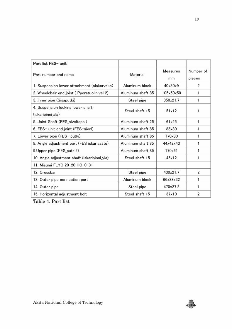
Table 4. Part list
Part list FES- unit
Part number and name Material Measures
mm
Number of
pieces
1. Suspension lower attachment (alakorvake) Aluminum block 40x30x9 2
2. Wheelchair end joint ( Pyoratuolinivel 2) Aluminum shaft 85 105x50x50 1
3. Inner pipe (Sisaputki) Steel pipe 350x21.7 1
4. Suspension locking lower shaft
(iskaripinni_ala) Steel shaft 15 51x12 1
5. Joint Shaft (FES_niveltappi) Aluminum shaft 25 61x25 1
6. FES- unit end joint (FES-nivel) Aluminum shaft 85 85x80 1
7. Lower pipe (FES- putki) Aluminum shaft 85 170x80 1
8. Angle adjustment part (FES_iskarisaato) Aluminum shaft 85 44x42x43 1
9.Upper pipe (FES_putki2) Aluminum shaft 85 170x61 1
10. Angle adjustment shaft (iskaripinni_yla) Steel shaft 15 45x12 1
11. Misumi FLYC 20-20 HC-0-31
12. Crossbar Steel pipe 430x21.7 2
13. Outer pipe connection part Aluminum block 66x38x32 1
14. Outer pipe Steel pipe 470x27.2 1
15. Horizontal adjustment bolt Steel shaft 15 37x10 2
20
Akita National College of Technology
3. MANUFACTURING PARTS
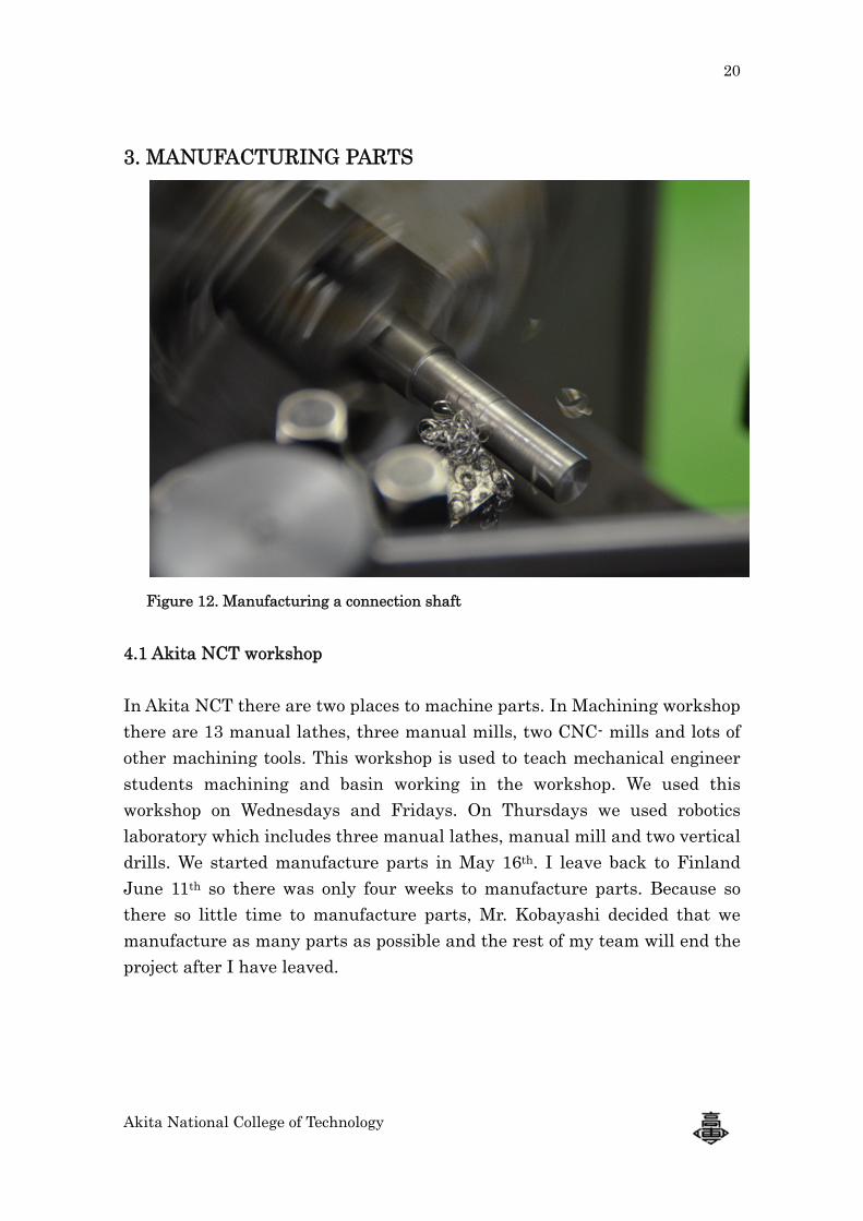
Figure 12. Manufacturing a connection shaft 4.1 Akita NCT workshop In Akita NCT there are two places to machine parts. In Machining workshop there are 13 manual lathes, three manual mills, two CNC- mills and lots of other machining tools. This workshop is used to teach mechanical engineer students machining and basin working in the workshop. We used this workshop on Wednesdays and Fridays. On Thursdays we used robotics laboratory which includes three manual lathes, manual mill and two vertical drills. We started manufacture parts in May 16th. I leave back to Finland June 11th so there was only four weeks to manufacture parts. Because so there so little time to manufacture parts, Mr. Kobayashi decided that we manufacture as many parts as possible and the rest of my team will end the project after I have leaved.
21
Akita National College of Technology
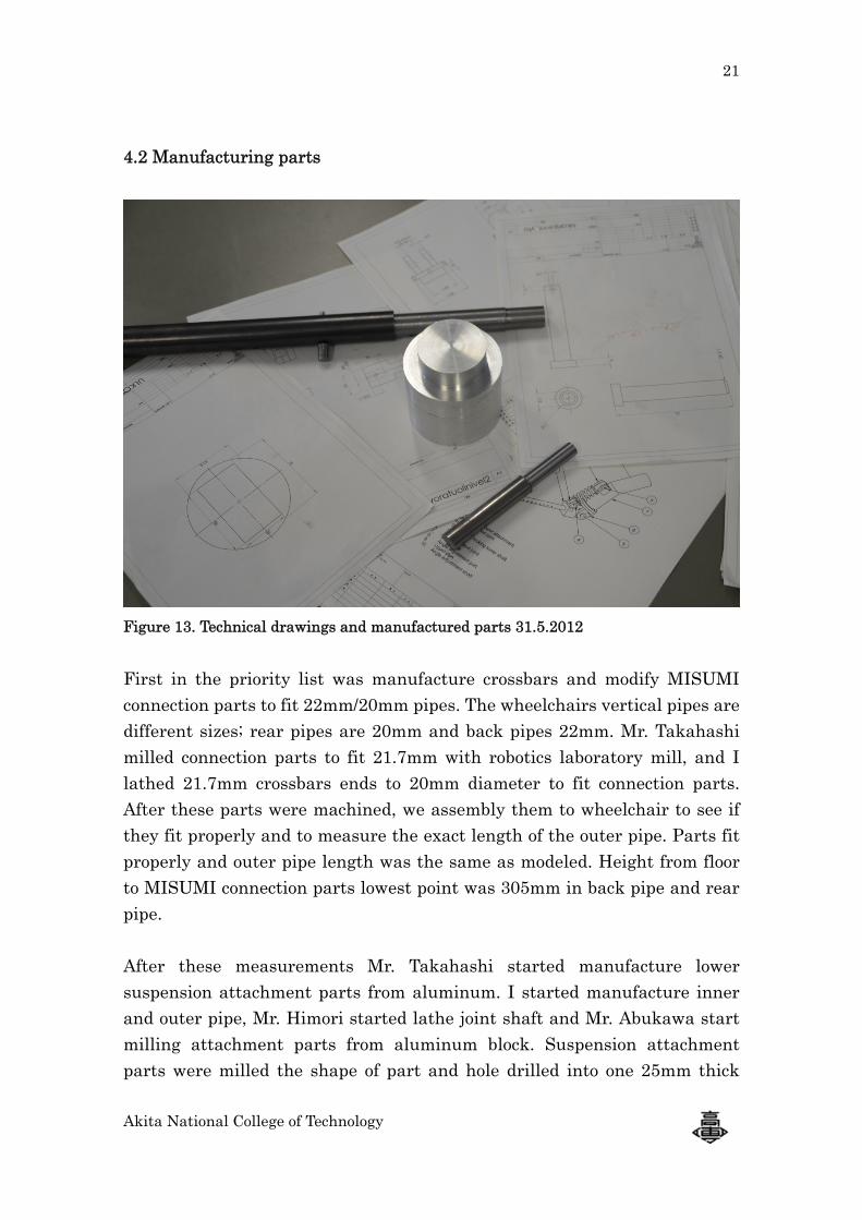
4.2 Manufacturing parts
Figure 13. Technical drawings and manufactured parts 31.5.2012 First in the priority list was manufacture crossbars and modify MISUMI connection parts to fit 22mm/20mm pipes. The wheelchairs vertical pipes are different sizes; rear pipes are 20mm and back pipes 22mm. Mr. Takahashi milled connection parts to fit 21.7mm with robotics laboratory mill, and I lathed 21.7mm crossbars ends to 20mm diameter to fit connection parts. After these parts were machined, we assembly them to wheelchair to see if they fit properly and to measure the exact length of the outer pipe. Parts fit properly and outer pipe length was the same as modeled. Height from floor to MISUMI connection parts lowest point was 305mm in back pipe and rear pipe. After these measurements Mr. Takahashi started manufacture lower suspension attachment parts from aluminum. I started manufacture inner and outer pipe, Mr. Himori started lathe joint shaft and Mr. Abukawa start milling attachment parts from aluminum block. Suspension attachment parts were milled the shape of part and hole drilled into one 25mm thick
22
Akita National College of Technology
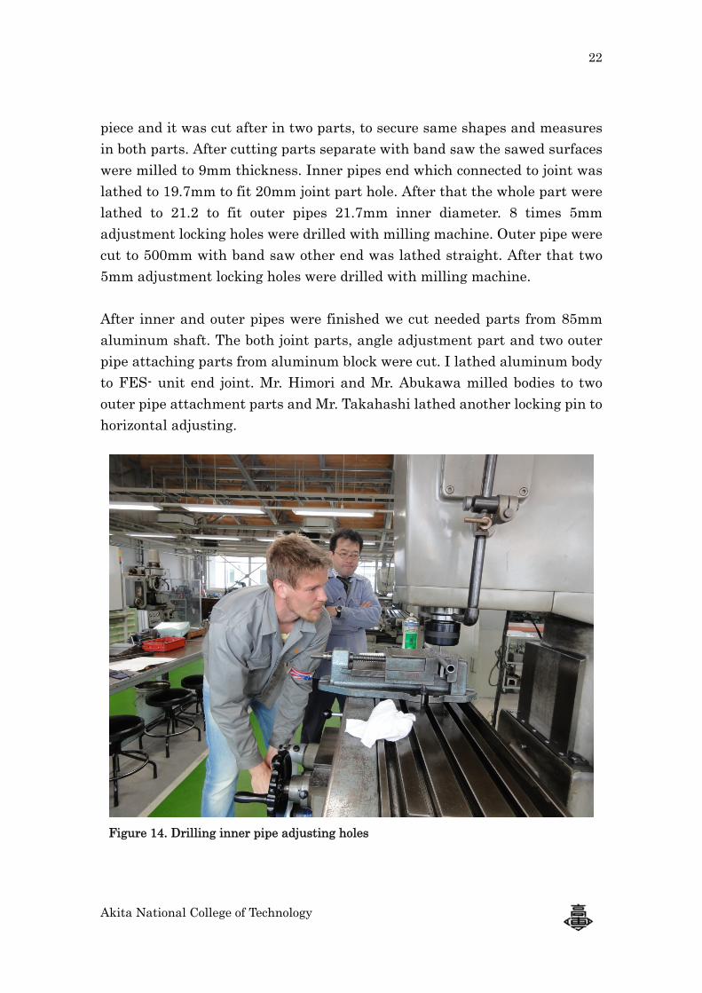
piece and it was cut after in two parts, to secure same shapes and measures in both parts. After cutting parts separate with band saw the sawed surfaces were milled to 9mm thickness. Inner pipes end which connected to joint was lathed to 19.7mm to fit 20mm joint part hole. After that the whole part were lathed to 21.2 to fit outer pipes 21.7mm inner diameter. 8 times 5mm adjustment locking holes were drilled with milling machine. Outer pipe were cut to 500mm with band saw other end was lathed straight. After that two 5mm adjustment locking holes were drilled with milling machine. After inner and outer pipes were finished we cut needed parts from 85mm aluminum shaft. The both joint parts, angle adjustment part and two outer pipe attaching parts from aluminum block were cut. I lathed aluminum body to FES- unit end joint. Mr. Himori and Mr. Abukawa milled bodies to two outer pipe attachment parts and Mr. Takahashi lathed another locking pin to horizontal adjusting.
Figure 14. Drilling inner pipe adjusting holes
23
Akita National College of Technology
On last week of work placement I finished my report, experiences about Japan and Accomplishment report which go to JASSO. Workshop mechanic milled with CNC- mill the FES- unit end joint part. Mr. Koosei and Mr. Yoshiyaki drill and lathed holes to outer pipe attachment parts and after that they started to mill aluminum body to wheelchair end joint part from the cylinder which I lathed last week. When week and my project part ends there were approximately 70% parts machined and manufactured to end.
24
Akita National College of Technology
Summary The project was from the start very interesting and I was highly motivated through project. Working with human anatomy and developing something which can help SCI patient in daily life and also give opportunity to cycle again was really interesting and give me a lot. The task was to redesign FES- cycling unit and solve problems in it and manufacture parts to new FES- cycling unit. This task was really close to my major mechanical engineering and I studied lot of designing in Turku University of Applied Sciences. The group working and doing things together was success even the language barrier was first high. Special thanks to successful communication in-group goes to Mr. Kobayashi and Siti Radziah Yusoff. Two and half months were short time to solve problems of old FES- unit and develop new one. The designing process takes almost one and half month and only one month was left to part manufacturing. That’s why rest of group will finish the project after I left back to Finland. They will send me the report of finished product and that will end my job in this project. The project itself, language, strange machines and people was challenge in the start but thanks to Japanese people and their kindness this project turn to success. I developed in professional skills, language and communication skills and especially group working skills. I had also change to give my own professional skills to other group members.
25
Akita National College of Technology
Appendix
FES- cycling, Rick Berkelmans, Journal of automatic control, University of Belgrade Vol. 18(2): 73-76, 2008
A pilot study of lower-limb FES- cycling in Paraplegia, K.J. Hunt, T. Shauer, N. Negard, W. Steward, M.H. Frasier, University of Glasgow & Queen Elizabeth National Spinal Unit
Cycling for children with neuromuscular impairments using electrical stimulation – Development of tricycle- based systems, C.G.A McRae, T.E Johnston, R.T. Lauer, A.M. Tokay, S.C.K Lee, K.J. Hunt, Medical engineering and physics 31(2009) 650-659
Materials from earlier projects and discussions with Mr. Kobayashi
spring 2012