a.k.a. setting-less protection
TRANSCRIPT
1
Protection Based on Dynamic State Estimation (a.k.a. Setting-less Protection):
Status and Vision Sakis Meliopoulos
Georgia Power Distinguished Professor School of Electrical and Computer Engineering
Georgia Institute of Technology Atlanta, Georgia 30332-0250
September 16, 2014
2
Contents
• History of Development
• DSE Based (aka Setting-less) Protection
• Examples of DSE Based Protection
• Laboratory Experimentation
• Integrated Protection & Control* Vision
• Dedicated Georgia Tech Laboratory
3
History of Developments
4
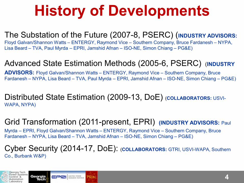
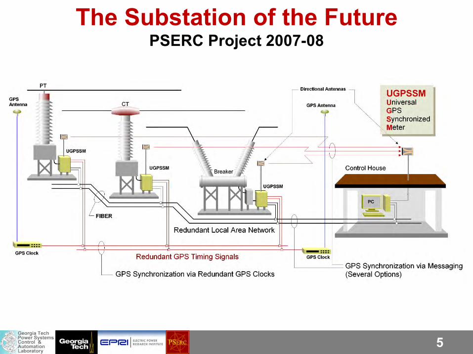
History of Developments The Substation of the Future (2007-8, PSERC) (INDUSTRY ADVISORS: Floyd Galvan/Shannon Watts – ENTERGY, Raymond Vice – Southern Company, Bruce Fardanesh – NYPA, Lisa Beard – TVA, Paul Myrda – EPRI, Jamshid Afnan – ISO-NE, Simon Chiang – PG&E)
Advanced State Estimation Methods (2005-6, PSERC) (INDUSTRY ADVISORS: Floyd Galvan/Shannon Watts – ENTERGY, Raymond Vice – Southern Company, Bruce Fardanesh – NYPA, Lisa Beard – TVA, Paul Myrda – EPRI, Jamshid Afnan – ISO-NE, Simon Chiang – PG&E)
Distributed State Estimation (2009-13, DoE) (COLLABORATORS: USVI-WAPA, NYPA)
Grid Transformation (2011-present, EPRI) (INDUSTRY ADVISORS: Paul Myrda – EPRI, Floyd Galvan/Shannon Watts – ENTERGY, Raymond Vice – Southern Company, Bruce Fardanesh – NYPA, Lisa Beard – TVA, Jamshid Afnan – ISO-NE, Simon Chiang – PG&E)
Cyber Security (2014-17, DoE): (COLLABORATORS: GTRI, USVI-WAPA, Southern Co., Burbank W&P)
5
The Substation of the Future PSERC Project 2007-08
6
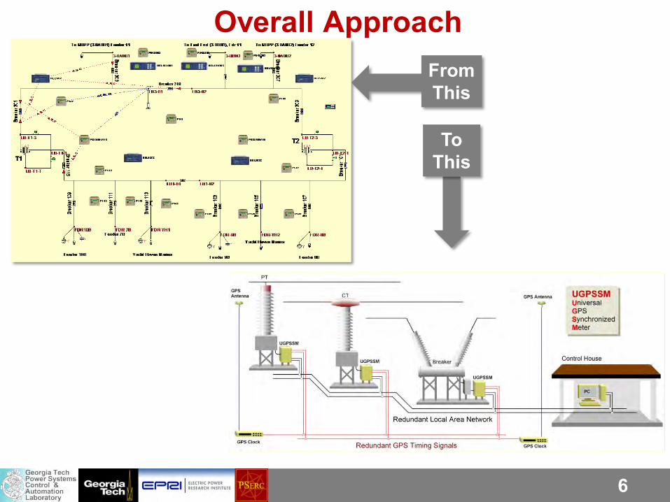
Overall Approach
From This
To This
7
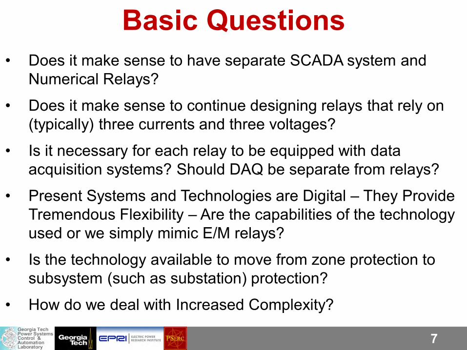
Basic Questions • Does it make sense to have separate SCADA system and
Numerical Relays?
• Does it make sense to continue designing relays that rely on (typically) three currents and three voltages?
• Is it necessary for each relay to be equipped with data acquisition systems? Should DAQ be separate from relays?
• Present Systems and Technologies are Digital – They Provide Tremendous Flexibility – Are the capabilities of the technology used or we simply mimic E/M relays?
• Is the technology available to move from zone protection to subsystem (such as substation) protection?
• How do we deal with Increased Complexity?
8
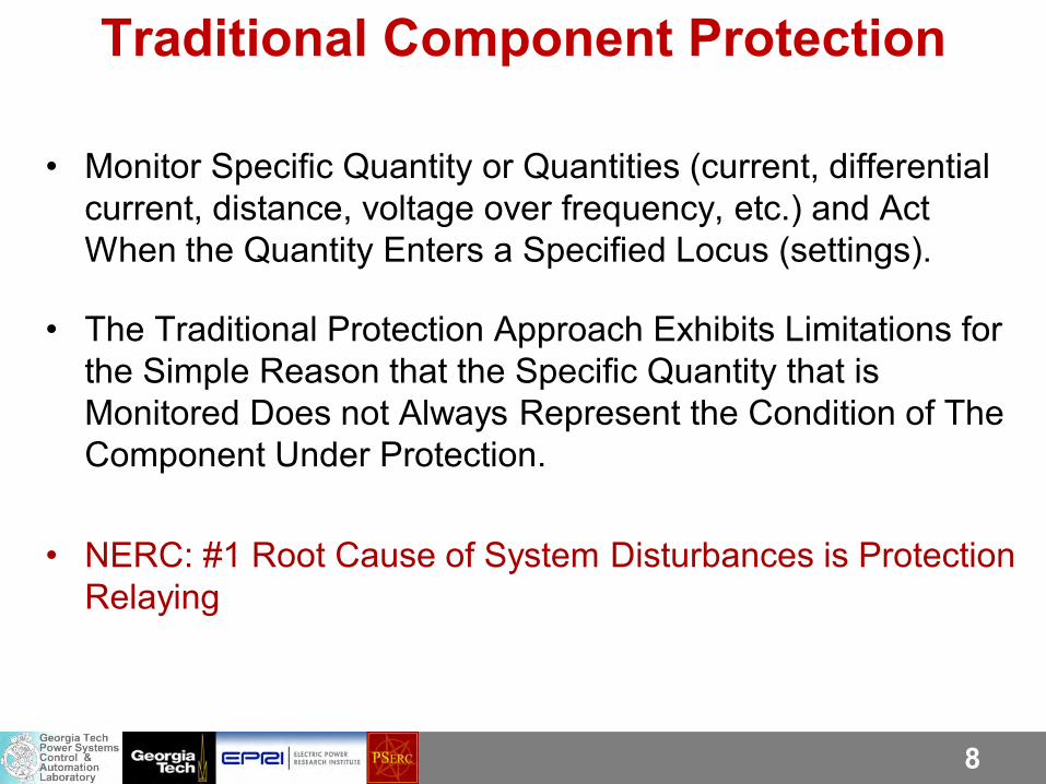
Traditional Component Protection
• Monitor Specific Quantity or Quantities (current, differential current, distance, voltage over frequency, etc.) and Act When the Quantity Enters a Specified Locus (settings).
• The Traditional Protection Approach Exhibits Limitations for the Simple Reason that the Specific Quantity that is Monitored Does not Always Represent the Condition of The Component Under Protection.
• NERC: #1 Root Cause of System Disturbances is Protection Relaying
9
Complexity, Gaps & Challenges A Modern Substation May Have Tens of Numerical Relays, each relay has an average of 12 protection functions. Coordination of all these relay functions is quite complex. Experts (humans) and Expert Systems (computers) are needed…
Tools to validate coordination of complex protection schemes are at best inadequate.
Protection Gaps: HIF, Down Conductors, Faults Near Neutrals, Inverter Interfaced Generation, Faults in Series Compensated Lines, etc. etc.
Protection Gaps Result in Fatalities…
10
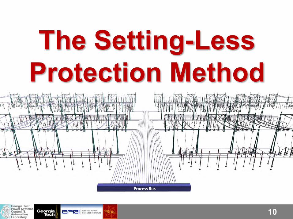
The Setting-Less Protection Method
11
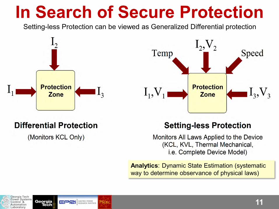
In Search of Secure Protection Setting-less Protection can be viewed as Generalized Differential protection
Analytics: Dynamic State Estimation (systematic way to determine observance of physical laws)
12
• Measure/Monitor as Many Quantities as Possible and Use Dynamic State Estimation to Continuously Monitor the State (Condition, Health) of the Zone (Component) Under Protection. Identify bad data, model changes, etc.
• Act on the Basis of the Zone (Component) State (Condition, Component Health).
• Advantage: No need to know what is happening in the rest of the system – no coordination needed.
The Zone Setting-less Protection Approach
13
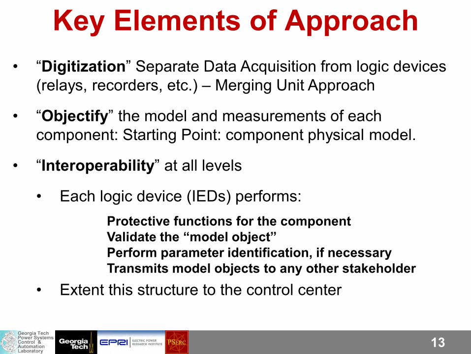
Key Elements of Approach • “Digitization” Separate Data Acquisition from logic devices
(relays, recorders, etc.) – Merging Unit Approach
• “Objectify” the model and measurements of each component: Starting Point: component physical model.
• “Interoperability” at all levels
• Each logic device (IEDs) performs: Protective functions for the component Validate the “model object” Perform parameter identification, if necessary Transmits model objects to any other stakeholder
• Extent this structure to the control center
14
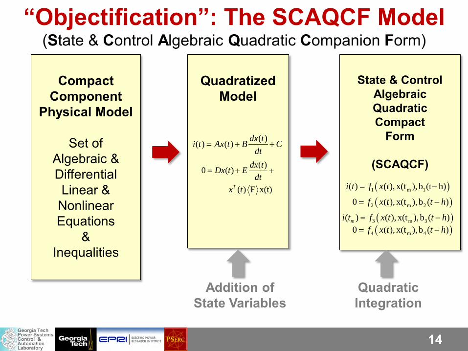
Compact
Component Physical Model
Set of
Algebraic & Differential Linear &
Nonlinear Equations
& Inequalities
Quadratized
Model
State & Control
Algebraic Quadratic Compact
Form
(SCAQCF)
Addition of State Variables
Quadratic Integration
“Objectification”: The SCAQCF Model (State & Control Algebraic Quadratic Companion Form)
( )( ) ( ) dx ti t Ax t B Cdt
= + +
( )0 ( )
( ) F x(t)T
dx tDx t Edt
x t
= + +
( )1 m 1( ) ( ), x(t ), b (t h)i t f x t= −
( )2 m 20 ( ), x(t ), b ( )f x t t h= −
( )3 m 3( ) ( ), x(t ), b ( )mi t f x t t h= −( )4 m 40 ( ), x(t ), b ( )f x t t h= −
15
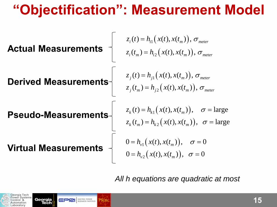
“Objectification”: Measurement Model
Actual Measurements Derived Measurements Pseudo-Measurements Virtual Measurements
( )1( ) ( ), ( ) ,i i m meterz t h x t x t σ=
( )2( ) ( ), ( ) ,i m i m meterz t h x t x t σ=
( )1( ) ( ), ( ) ,j j m meterz t h x t x t σ=
( )2( ) ( ), ( ) ,j m j m meterz t h x t x t σ=
( )2( ) ( ), ( ) , largek m k mz t h x t x t σ= =
( )1( ) ( ), ( ) , largek k mz t h x t x t σ= =
( )10 ( ), ( ) , 0v mh x t x t σ= =
( )20 ( ), ( ) , 0v mh x t x t σ= =
All h equations are quadratic at most
16
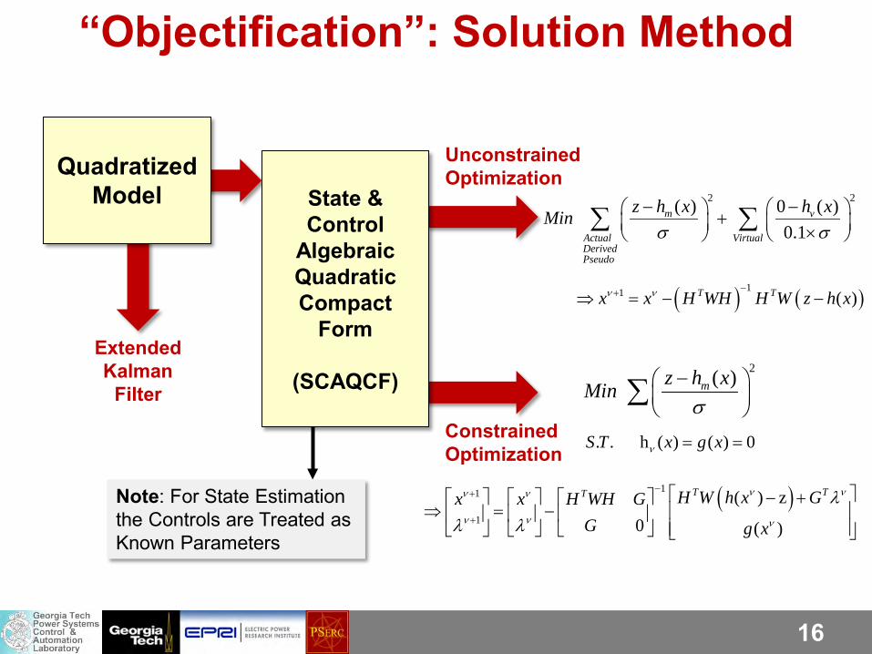
Quadratized
Model
State & Control
Algebraic Quadratic Compact
Form
(SCAQCF)
“Objectification”: Solution Method
Unconstrained Optimization
Constrained Optimization
Extended Kalman
Filter
2 2( ) 0 ( )0.1
m v
Actual VirtualDerivedPseudo
z h x h xMinσ σ
− − + × ∑ ∑
( ) ( )11 ( )T Tx x H WH H W z h xν ν −+⇒ = − −
2( )mz h xMinσ
−
∑. . h ( ) ( ) 0S T x g xν = =
( )11
1
( ) z0 ( )
T TT H W h x Gx x H WH GG g x
ν νν ν
ν ν ν
λλ λ
−+
+
− + ⇒ = −
Note: For State Estimation the Controls are Treated as Known Parameters
17
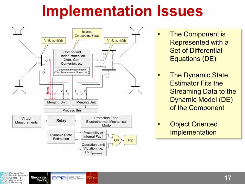
Implementation Issues • The Component is
Represented with a Set of Differential Equations (DE)
• The Dynamic State
Estimator Fits the Streaming Data to the Dynamic Model (DE) of the Component
• Object Oriented Implementation
18
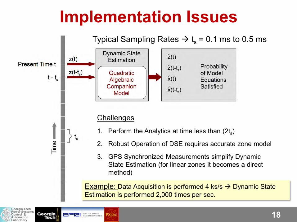
Challenges
1. Perform the Analytics at time less than (2ts)
2. Robust Operation of DSE requires accurate zone model
3. GPS Synchronized Measurements simplify Dynamic State Estimation (for linear zones it becomes a direct method)
Implementation Issues Typical Sampling Rates ts = 0.1 ms to 0.5 ms
Example: Data Acquisition is performed 4 ks/s Dynamic State Estimation is performed 2,000 times per sec.
19
Examples of DSE Based Protection
20
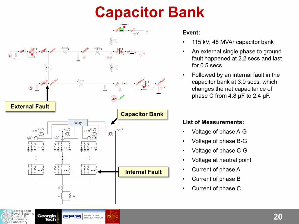
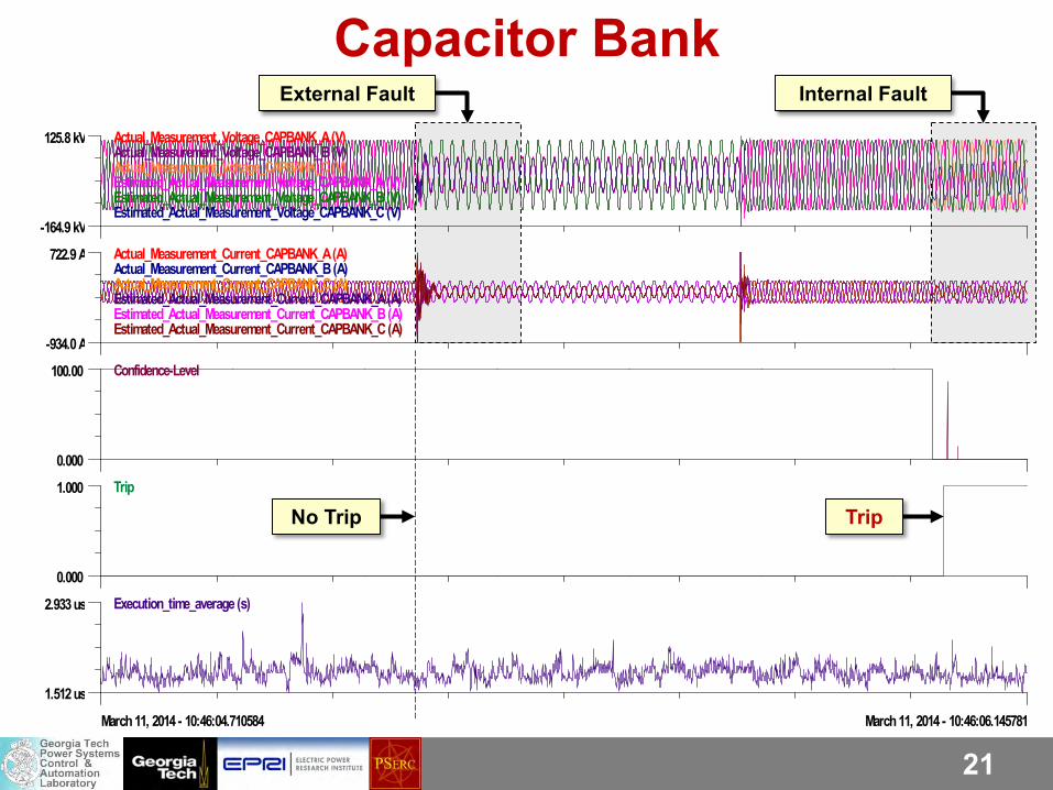
Event: • 115 kV, 48 MVAr capacitor bank • An external single phase to ground
fault happened at 2.2 secs and last for 0.5 secs
• Followed by an internal fault in the capacitor bank at 3.0 secs, which changes the net capacitance of phase C from 4.8 μF to 2.4 μF.
G
1 2
G
1 2 1 2
GEN CAPBNK
CAP1GUNIT2
JCLIN
E3
LINE
LINETEE
LOAD04
SOURCE1
SOURCE1-T
TXFMRHIGH
TXFMRLO
W
XFMR2H
XFMR2L
YJLINE1
YJLINE2
List of Measurements: • Voltage of phase A-G • Voltage of phase B-G • Voltage of phase C-G • Voltage at neutral point • Current of phase A • Current of phase B • Current of phase C
Capacitor Bank
External Fault Capacitor Bank
Internal Fault
21
External Fault Internal Fault
Capacitor Bank 125.8 kV
-164.9 kV
Actual_Measurement_Voltage_CAPBANK_A (V)Actual_Measurement_Voltage_CAPBANK_B (V)Actual_Measurement_Voltage_CAPBANK_C (V)Estimated_Actual_Measurement_Voltage_CAPBANK_A (V)Estimated_Actual_Measurement_Voltage_CAPBANK_B (V)Estimated_Actual_Measurement_Voltage_CAPBANK_C (V)
722.9 A
-934.0 A
Actual_Measurement_Current_CAPBANK_A (A)Actual_Measurement_Current_CAPBANK_B (A)Actual_Measurement_Current_CAPBANK_C (A)Estimated_Actual_Measurement_Current_CAPBANK_A (A)Estimated_Actual_Measurement_Current_CAPBANK_B (A)Estimated_Actual_Measurement_Current_CAPBANK_C (A)
100.00
0.000
Confidence-Level
1.000
0.000
Trip
2.933 us
1.512 us
Execution_time_average (s)
March 11, 2014 - 10:46:04.710584 March 11, 2014 - 10:46:06.145781
No Trip Trip
22
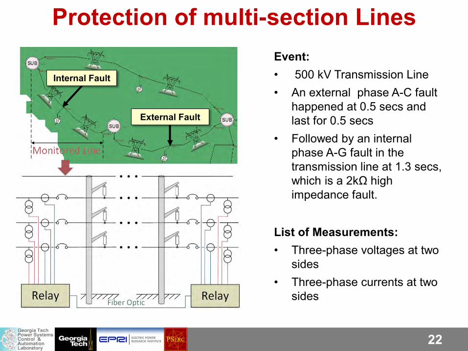
Protection of multi-section Lines Event: • 500 kV Transmission Line • An external phase A-C fault
happened at 0.5 secs and last for 0.5 secs
• Followed by an internal phase A-G fault in the transmission line at 1.3 secs, which is a 2kΩ high impedance fault.
List of Measurements: • Three-phase voltages at two
sides • Three-phase currents at two
sides
External Fault
Internal Fault
23
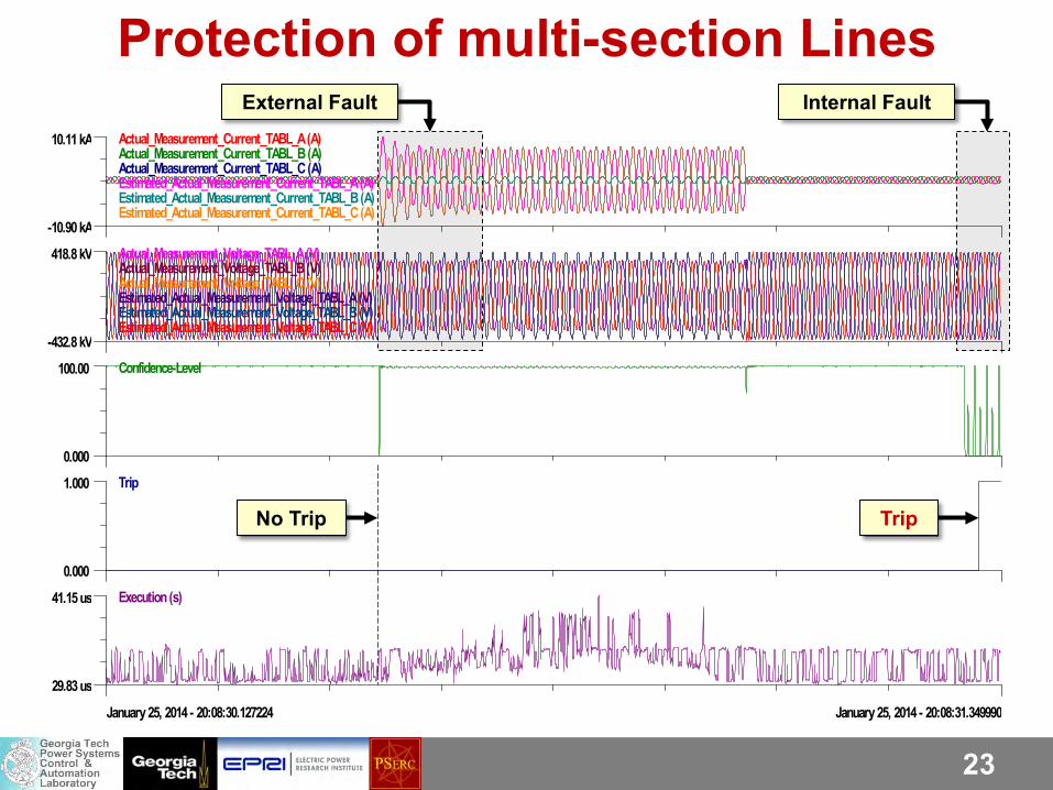
External Fault Internal Fault 10.11 kA
-10.90 kA
Actual_Measurement_Current_TABL_A (A)Actual_Measurement_Current_TABL_B (A)Actual_Measurement_Current_TABL_C (A)Estimated_Actual_Measurement_Current_TABL_A (A)Estimated_Actual_Measurement_Current_TABL_B (A)Estimated_Actual_Measurement_Current_TABL_C (A)
418.8 kV
-432.8 kV
Actual_Measurement_Voltage_TABL_A (V)Actual_Measurement_Voltage_TABL_B (V)Actual_Measurement_Voltage_TABL_C (V)Estimated_Actual_Measurement_Voltage_TABL_A (V)Estimated_Actual_Measurement_Voltage_TABL_B (V)Estimated_Actual_Measurement_Voltage_TABL_C (V)
100.00
0.000
Confidence-Level
1.000
0.000
Trip
41.15 us
29.83 us
Execution (s)
January 25, 2014 - 20:08:30.127224 January 25, 2014 - 20:08:31.349990
No Trip Trip
Protection of multi-section Lines
24
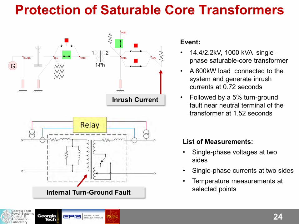
Protection of Saturable Core Transformers
Event: • 14.4/2.2kV, 1000 kVA single-
phase saturable-core transformer • A 800kW load connected to the
system and generate inrush currents at 0.72 seconds
• Followed by a 5% turn-ground fault near neutral terminal of the transformer at 1.52 seconds
List of Measurements: • Single-phase voltages at two
sides • Single-phase currents at two sides • Temperature measurements at
selected points
1 2
1-PhG
FAULT
LINE LOADSOURCE XFMRH XFMRL
Internal Turn-Ground Fault
Inrush Current
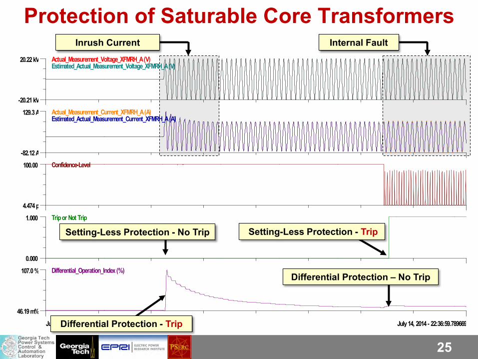
25
20.22 kV
-20.21 kV
Actual_Measurement_Voltage_XFMRH_A (V)Estimated_Actual_Measurement_Voltage_XFMRH_A (V)
129.3 A
-82.12 A
Actual_Measurement_Current_XFMRH_A (A)Estimated_Actual_Measurement_Current_XFMRH_A (A)
100.00
4.474 p
Confidence-Level
1.000
0.000
Trip or Not Trip
107.0 %
46.19 m%
Differential_Operation_Index (%)
July 14, 2014 - 22:36:58.315318 July 14, 2014 - 22:36:59.789669
Setting-Less Protection - No Trip Setting-Less Protection - Trip
Differential Protection - Trip
Differential Protection – No Trip
Inrush Current Internal Fault
Protection of Saturable Core Transformers
26
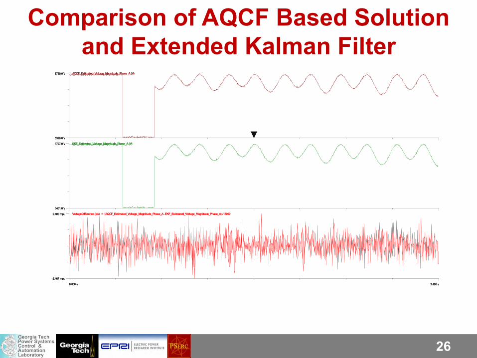
Comparison of AQCF Based Solution and Extended Kalman Filter
8739.0 V
5399.0 V
AQCF_Estimated_Voltage_Magnitude_Phase_A (V)
8727.0 V
5401.0 V
EKF_Estimated_Voltage_Magnitude_Phase_A (V)
2.400 mpu
-2.467 mpu
VoltageDifference (pu) = (AQCF_Estimated_Voltage_Magnitude_Phase_A -EKF_Estimated_Voltage_Magnitude_Phase_A) /15000
0.000 s 3.496 s
27
Laboratory Experimentation
28
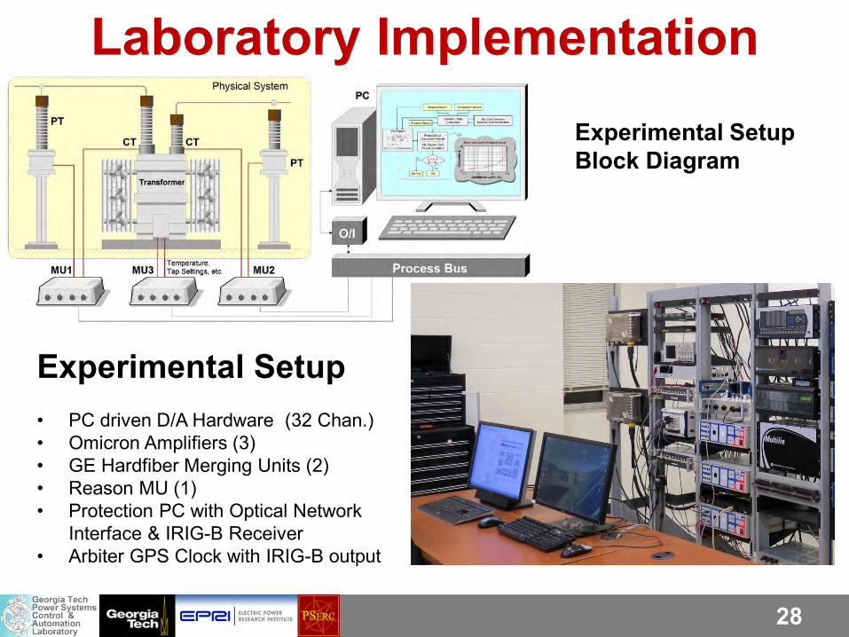
Laboratory Implementation Experimental Setup Block Diagram
Experimental Setup • PC driven D/A Hardware (32 Chan.) • Omicron Amplifiers (3) • GE Hardfiber Merging Units (2) • Reason MU (1) • Protection PC with Optical Network
Interface & IRIG-B Receiver • Arbiter GPS Clock with IRIG-B output
29
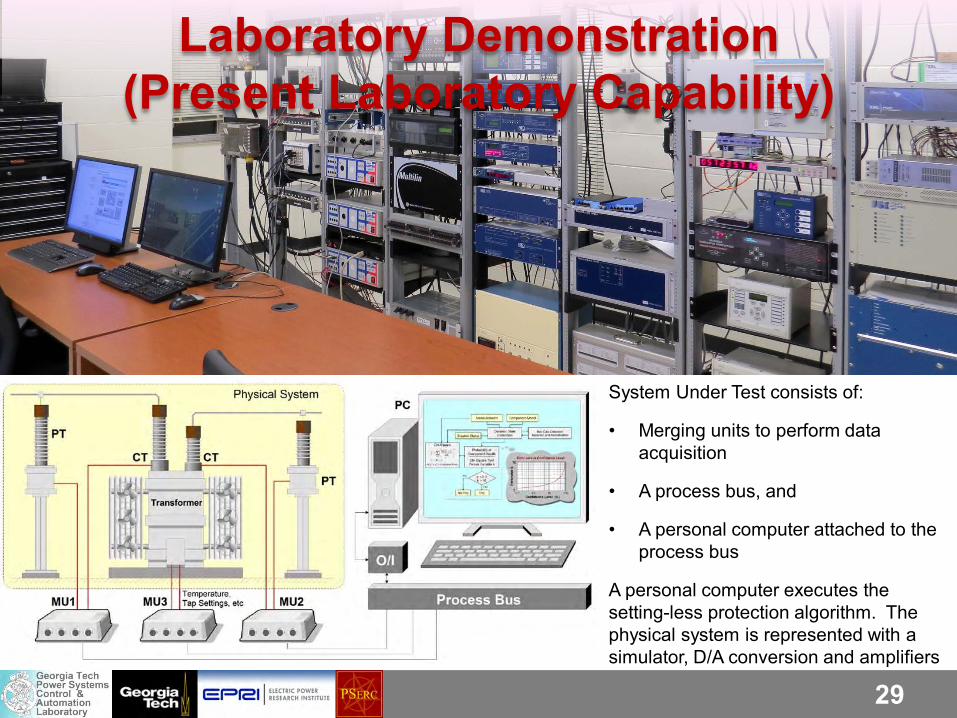
Laboratory Demonstration (Present Laboratory Capability)
System Under Test consists of:
• Merging units to perform data acquisition
• A process bus, and
• A personal computer attached to the process bus
A personal computer executes the setting-less protection algorithm. The physical system is represented with a simulator, D/A conversion and amplifiers
30
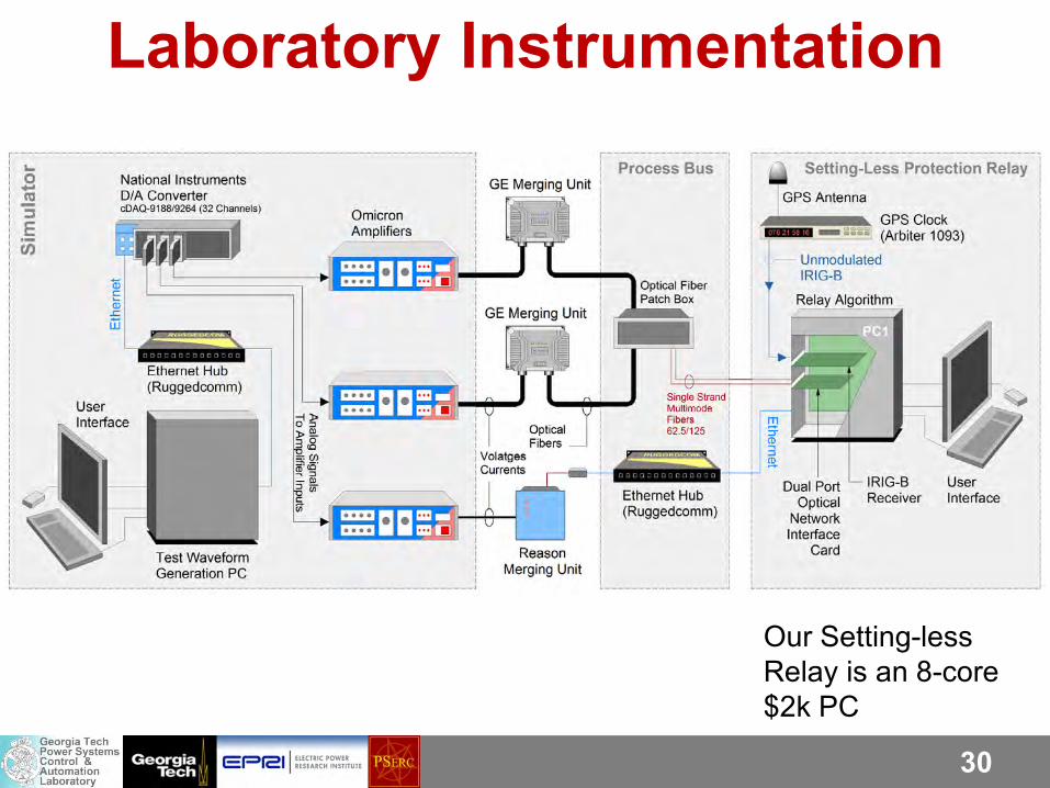
Laboratory Instrumentation
Our Setting-less Relay is an 8-core $2k PC
31
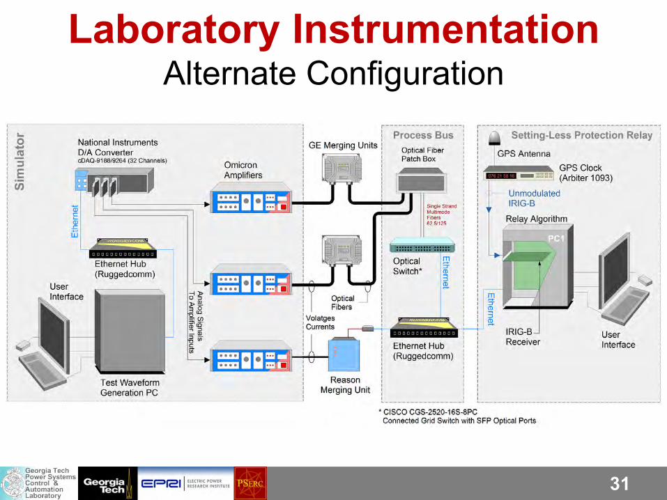
Laboratory Instrumentation Alternate Configuration
32
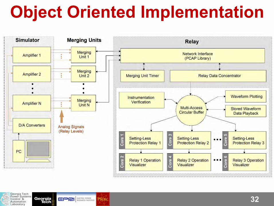
Object Oriented Implementation
33
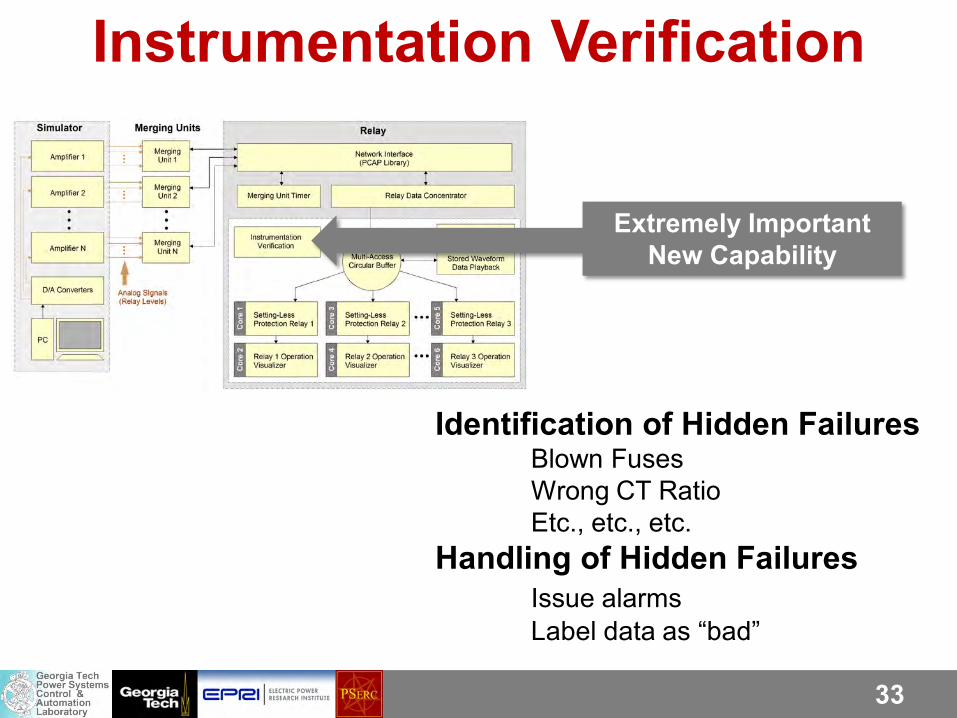
Instrumentation Verification
Extremely Important New Capability
Identification of Hidden Failures Blown Fuses Wrong CT Ratio Etc., etc., etc. Handling of Hidden Failures Issue alarms Label data as “bad”
34
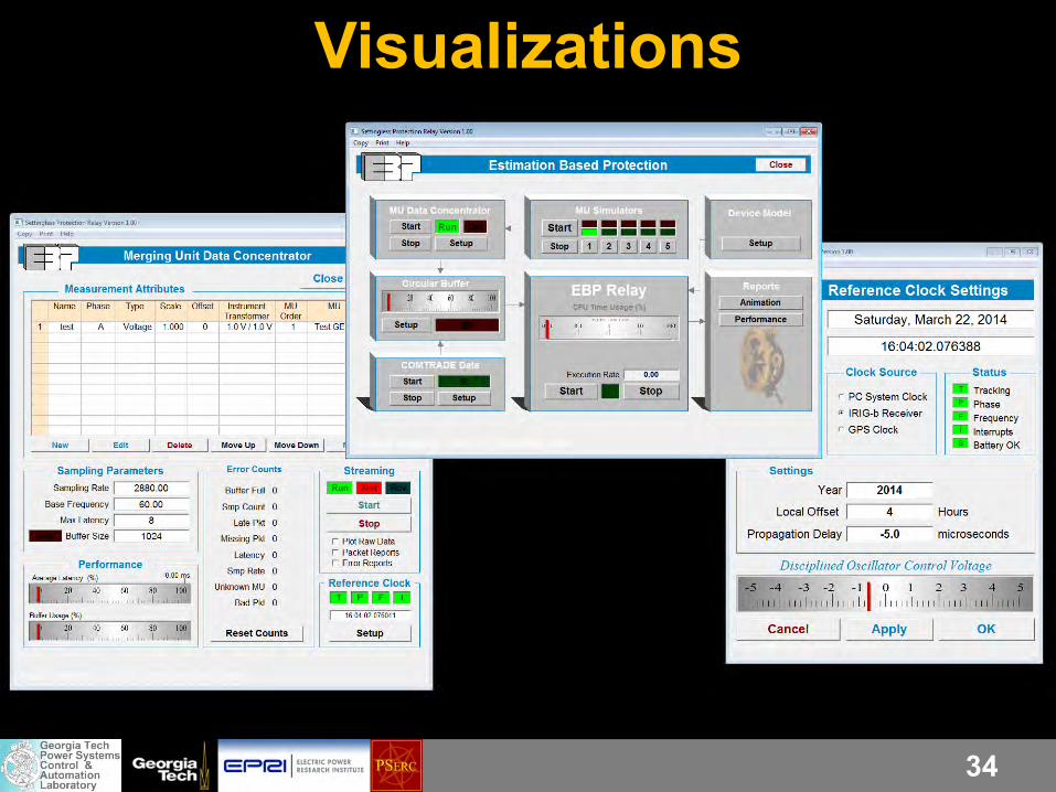
Visualizations
35
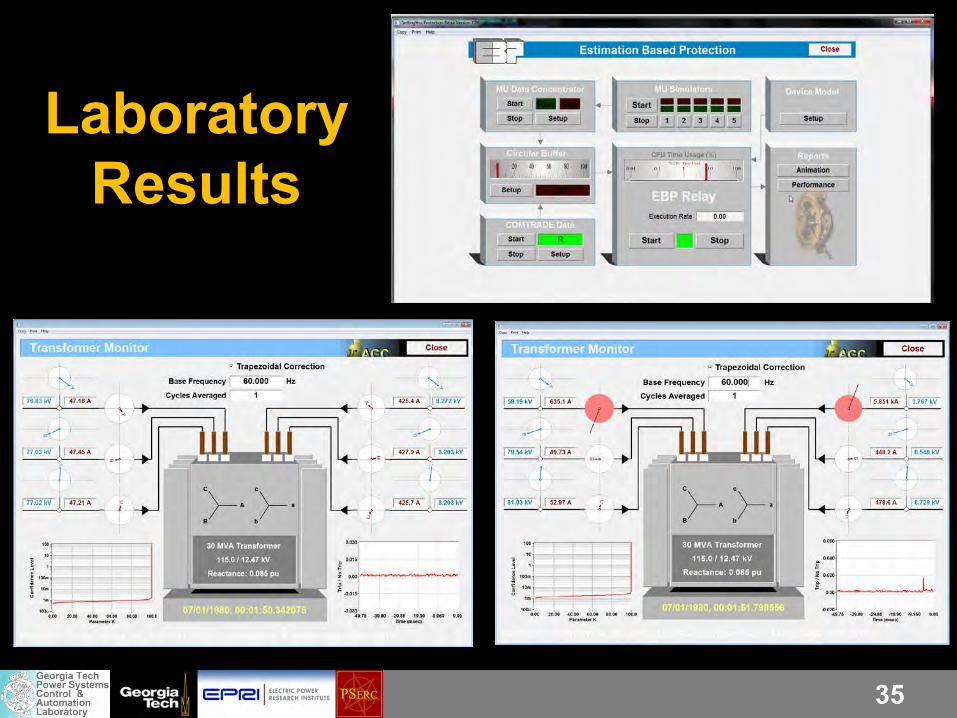
Laboratory Results
36
Technology Issues - MU • Use of Merging Units is preferable for the Dynamic State
Estimation protection because MU data are of better quality and accuracy.
• Interoperability at the Process Bus Level ???
• Data Transmission Latencies may be significant and depend upon communication infrastructure organization and capabilities. Need additional work.
• Transmitted Data Organization Varies among Manufacturers, as IEC68150 does not specify “Application Service Data Unit” (ASDU) format
• The Process Bus implementation details vary greatly among Merging Unit manufacturers (eg: GE vs Reason/Alstom, Siemens, etc.)
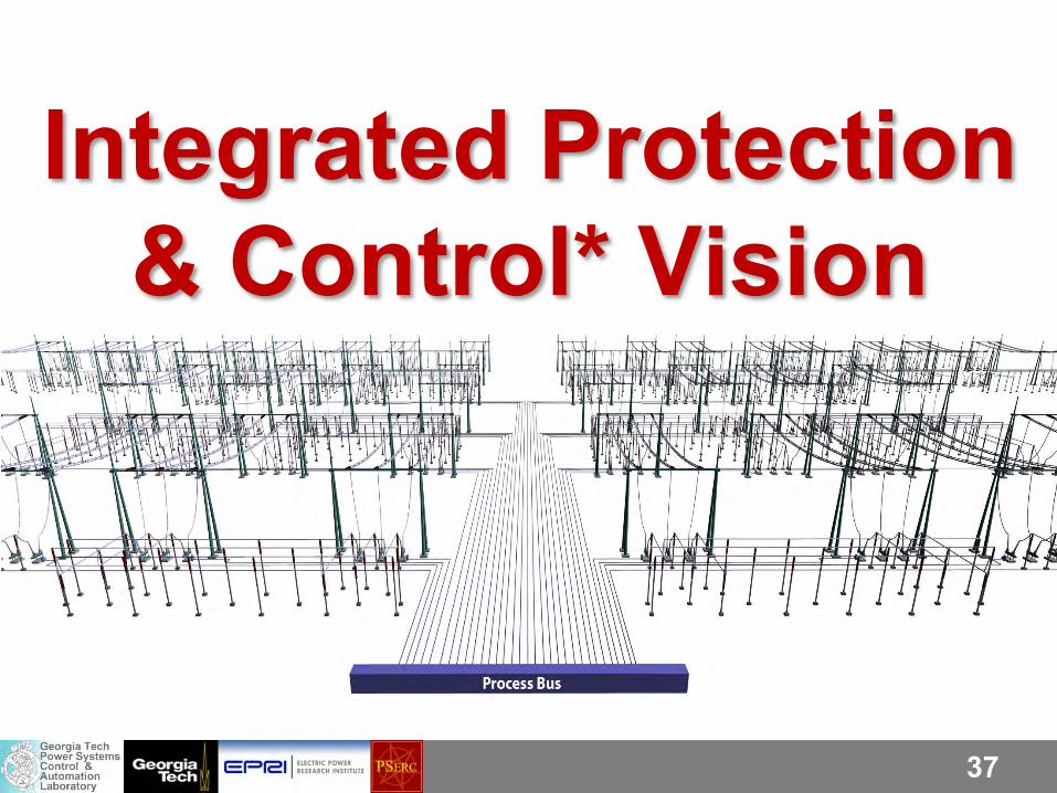
37
Integrated Protection & Control* Vision
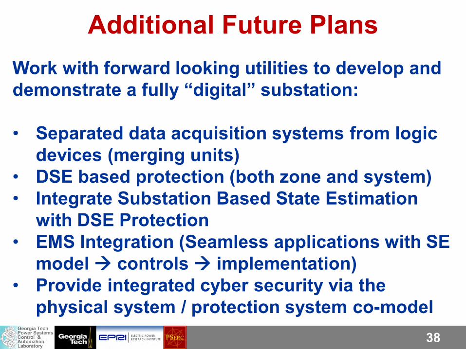
38
Additional Future Plans Work with forward looking utilities to develop and demonstrate a fully “digital” substation: • Separated data acquisition systems from logic
devices (merging units) • DSE based protection (both zone and system) • Integrate Substation Based State Estimation
with DSE Protection • EMS Integration (Seamless applications with SE
model controls implementation) • Provide integrated cyber security via the
physical system / protection system co-model
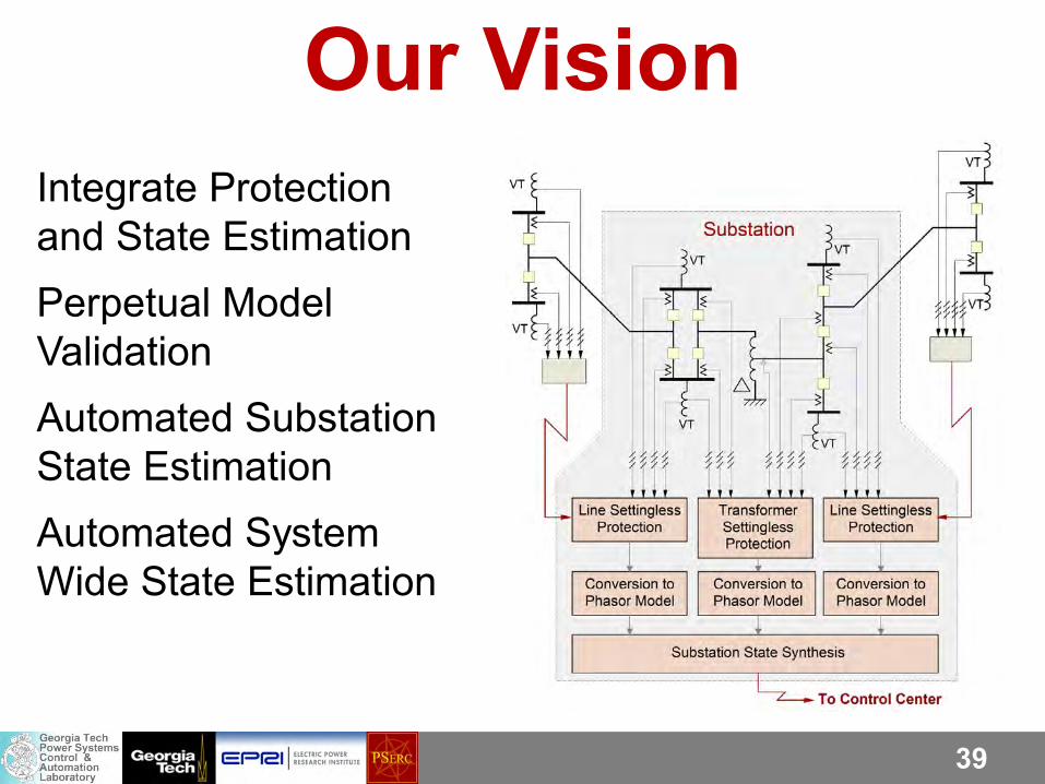
39
Our Vision Integrate Protection and State Estimation Perpetual Model Validation Automated Substation State Estimation Automated System Wide State Estimation
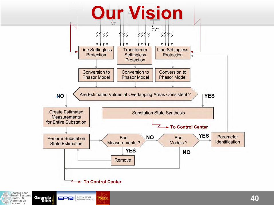
40
Our Vision
41
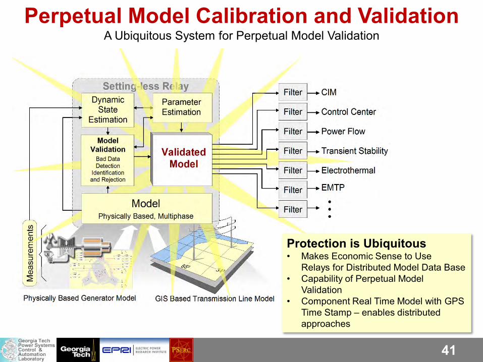
Perpetual Model Calibration and Validation A Ubiquitous System for Perpetual Model Validation
Protection is Ubiquitous • Makes Economic Sense to Use
Relays for Distributed Model Data Base • Capability of Perpetual Model
Validation • Component Real Time Model with GPS
Time Stamp – enables distributed approaches
42
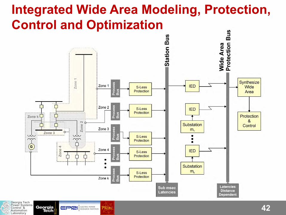
Integrated Wide Area Modeling, Protection, Control and Optimization
43
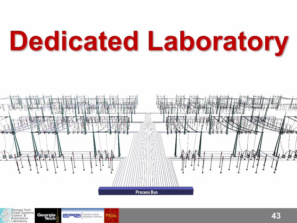
Dedicated Laboratory

44
Laboratory Demonstration (Present Laboratory Capability)
System Under Test consists of:
• Merging units to perform data acquisition
• A process bus, and
• A personal computer attached to the process bus
A personal computer executes the setting-less protection algorithm. The physical system is represented with a simulator, D/A conversion and amplifiers
45
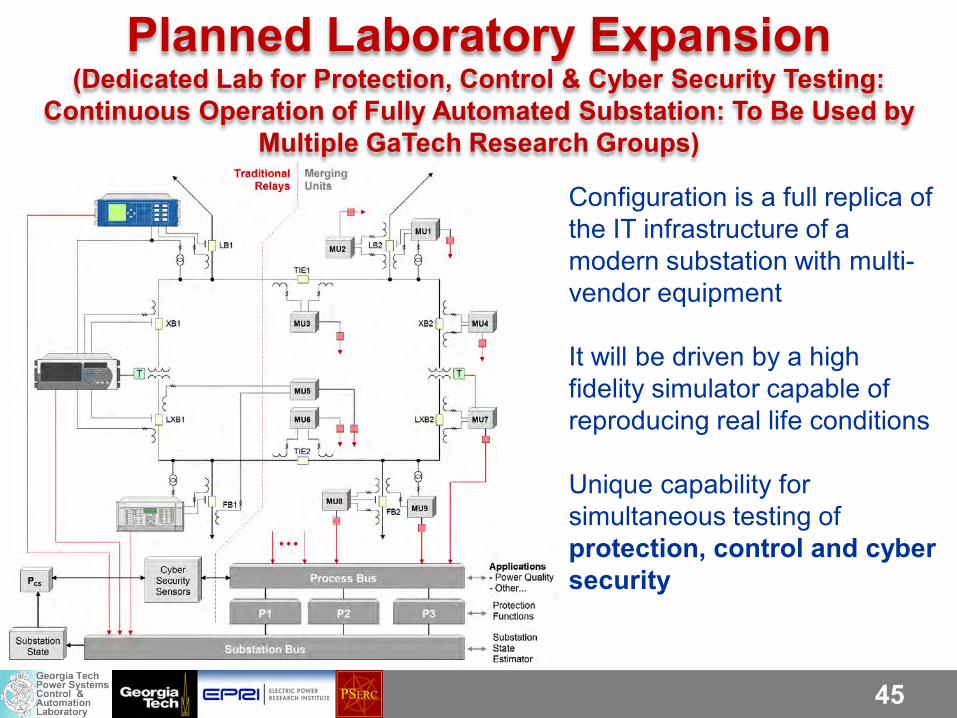
Planned Laboratory Expansion (Dedicated Lab for Protection, Control & Cyber Security Testing:
Continuous Operation of Fully Automated Substation: To Be Used by Multiple GaTech Research Groups)
Configuration is a full replica of the IT infrastructure of a modern substation with multi-vendor equipment It will be driven by a high fidelity simulator capable of reproducing real life conditions Unique capability for simultaneous testing of protection, control and cyber security
46
Acknowledgments We have collaborated with many folks over the years and it is impossible to list all. Paul Myrda for his vision of the Grid Transformation and coining the term “setting-less protection” Anjan Bose, Jerry Heydt, Ali Abur, Mladen Kezunovic, Vijay Vittal, Tom Overbye for their collaboration in key projects The folks in NYPA, Southern Co, TVA, PG&E and ENTERGY for their support in several key projects PSERC, DoE, EPRI, NSF, NYPA, Southern Co, TVA, PG&E and ENTERGY for the financial support over the years Prof. Cokkinides and numerous GT students

47
Τέλος