airfoil nomenclature
DESCRIPTION
airfoilTRANSCRIPT
AIRFOIL NOMENCLATURE
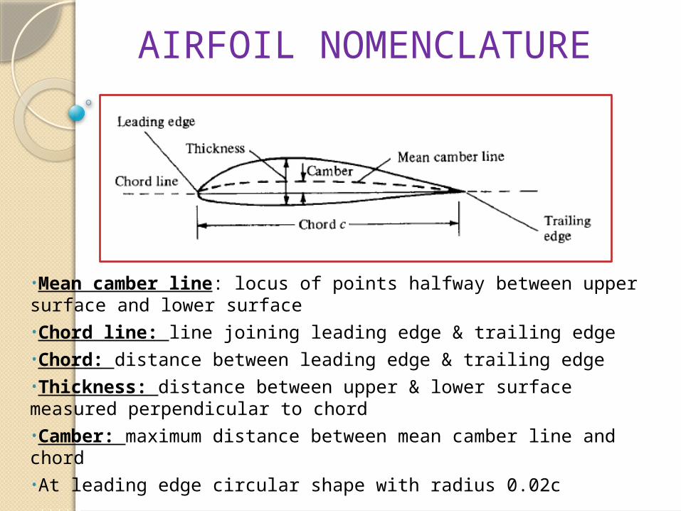
•Mean camber line: locus of points halfway between upper surface and lower surface•Chord line: line joining leading edge & trailing edge•Chord: distance between leading edge & trailing edge•Thickness: distance between upper & lower surface measured perpendicular to chord•Camber: maximum distance between mean camber line and chord•At leading edge circular shape with radius 0.02c
AIRFOIL DESIGN:
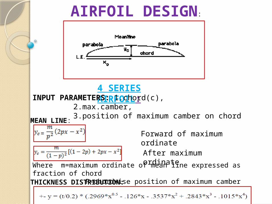
4 SERIES AIRFOIL:
THICKNESS DISTRIBUTION:
MEAN LINE:
INPUT PARAMETERS: 1.chord(c),2.max.camber,3.position of maximum camber on chord
Forward of maximum ordinate
After maximum ordinate
Where m=maximum ordinate of mean line expressed as fraction of chord P=chordwise position of maximum camber
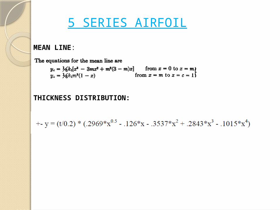
5 SERIES AIRFOIL
THICKNESS DISTRIBUTION:
MEAN LINE:
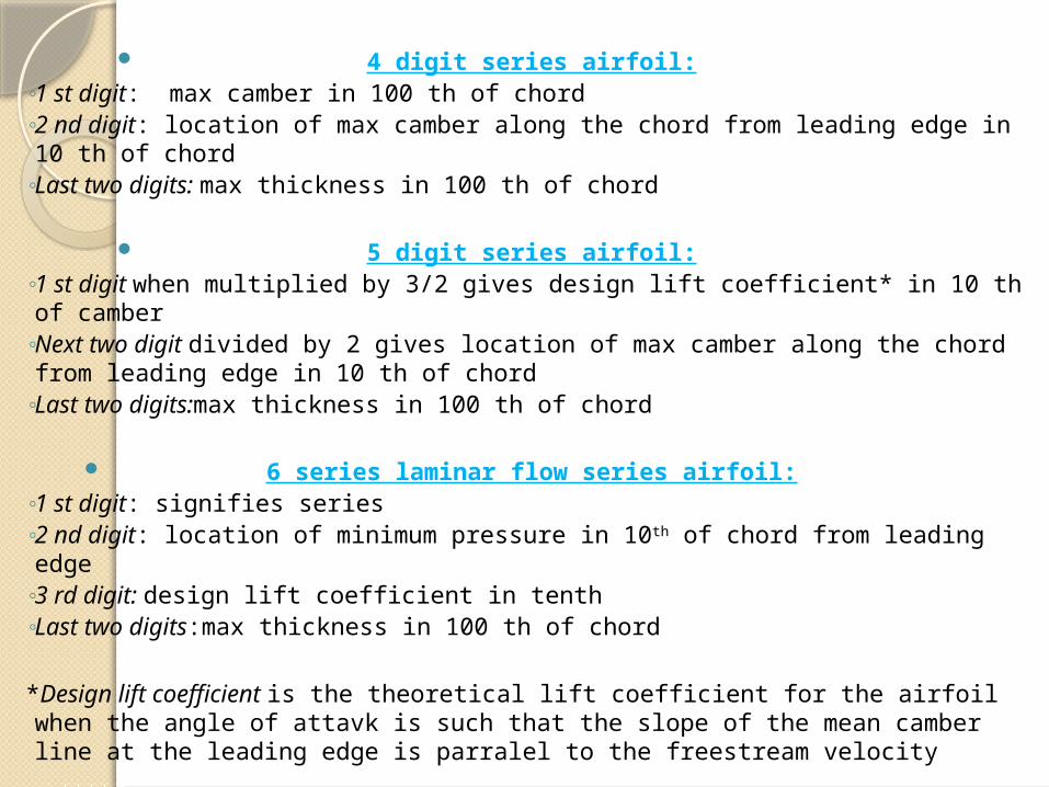
4 digit series airfoil:◦ 1 st digit: max camber in 100 th of chord◦ 2 nd digit: location of max camber along the chord from leading edge in 10 th of
chord◦ Last two digits: max thickness in 100 th of chord
5 digit series airfoil:◦ 1 st digit when multiplied by 3/2 gives design lift coefficient* in 10 th of camber◦ Next two digit divided by 2 gives location of max camber along the chord from
leading edge in 10 th of chord◦ Last two digits:max thickness in 100 th of chord
6 series laminar flow series airfoil:◦ 1 st digit: signifies series◦ 2 nd digit: location of minimum pressure in 10th of chord from leading edge◦ 3 rd digit: design lift coefficient in tenth◦ Last two digits:max thickness in 100 th of chord
*Design lift coefficient is the theoretical lift coefficient for the airfoil when the angle of attavk is such that the slope of the mean camber line at the leading edge is parralel to the freestream velocity
LIFT GENERATIONLift can be achieved in two ways:1.Cambered profile2.Angle of attack
video
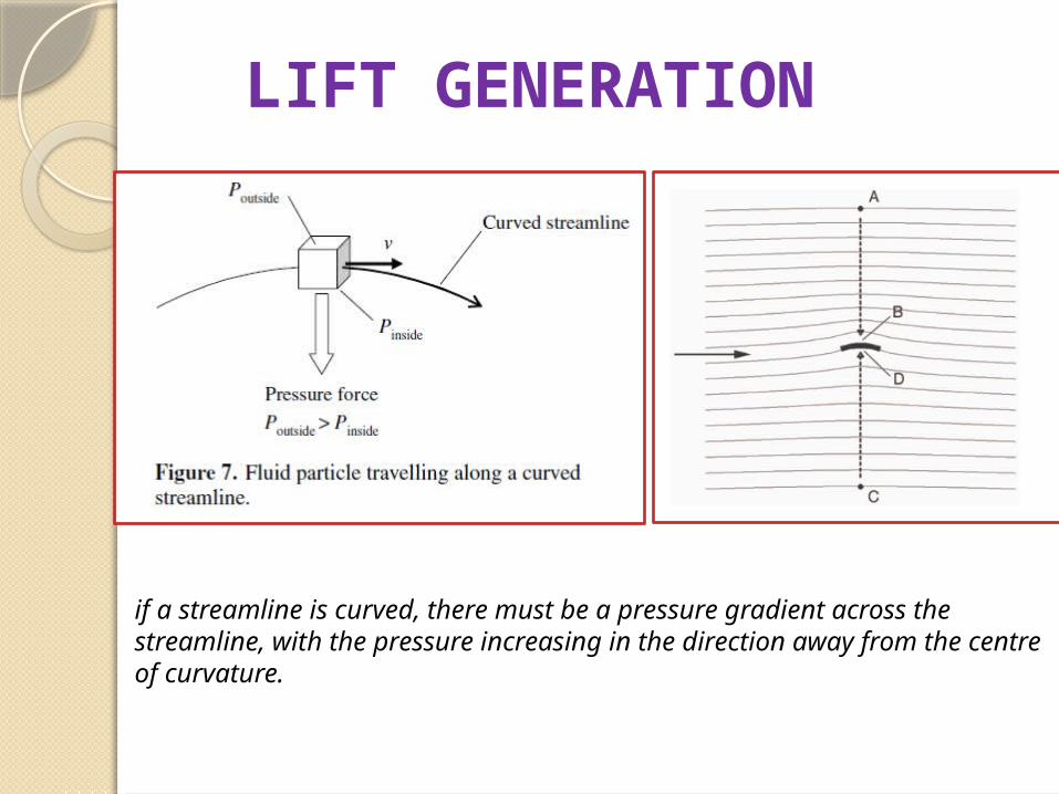
LIFT GENERATION
if a streamline is curved, there must be a pressure gradient across the streamline, with the pressure increasing in the direction away from the centre of curvature.
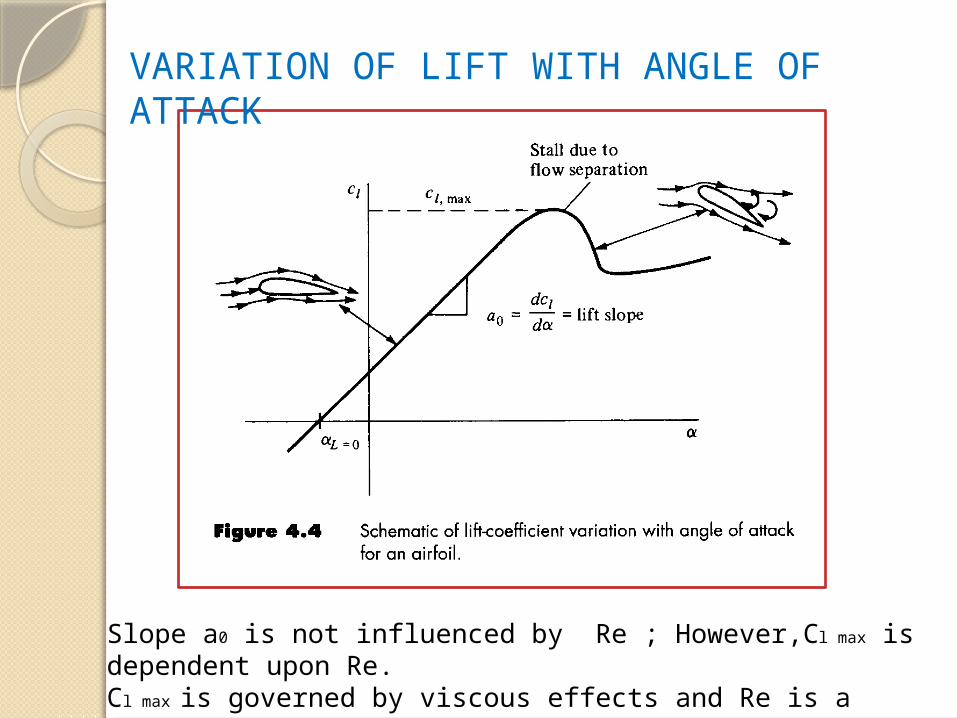
Slope a0 is not influenced by Re ; However,Cl max is dependent upon Re.Cl max is governed by viscous effects and Re is a similarity parameter that governs the strength of inertia forces relative to viscous forces in the flow
VARIATION OF LIFT WITH ANGLE OF ATTACK
VARIATION OF LIFT WITH CAMBER
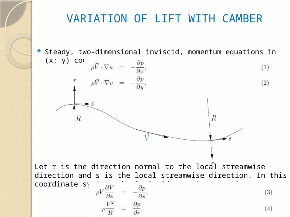
Steady, two-dimensional inviscid, momentum equations in (x; y) coordinates is,
Let r is the direction normal to the local streamwise direction and s is the local streamwise direction. In this coordinate system, the inviscid momentum equations are
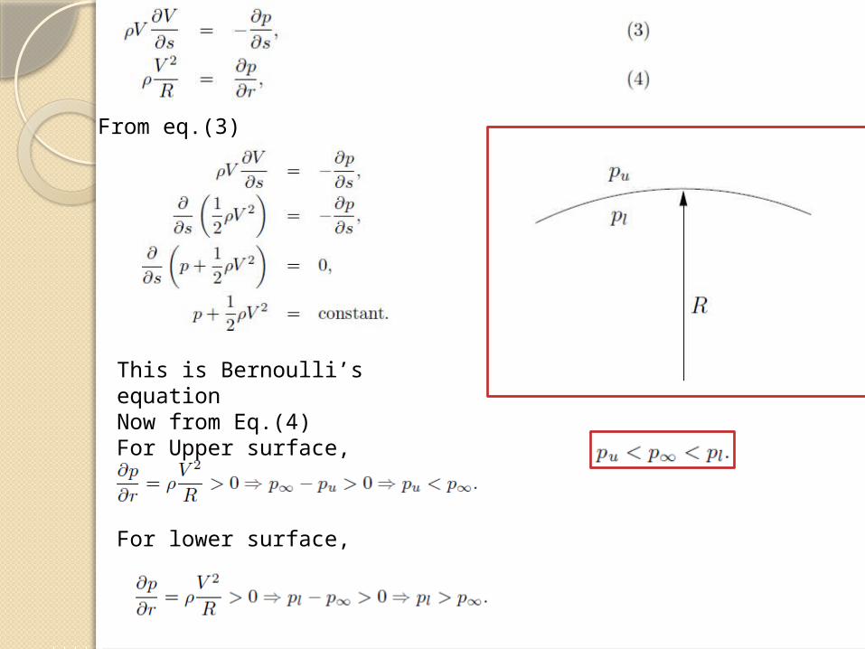
From eq.(3)
This is Bernoulli’s equationNow from Eq.(4)For Upper surface,
For lower surface,
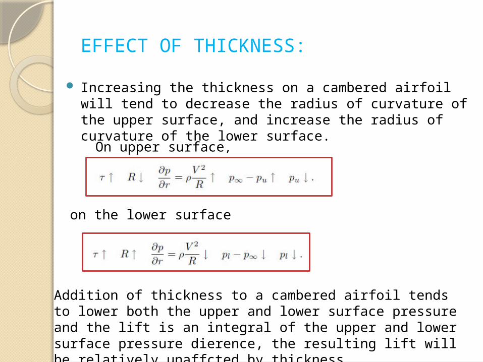
EFFECT OF THICKNESS:
Increasing the thickness on a cambered airfoil will tend to decrease the radius of curvature of the upper surface, and increase the radius of curvature of the lower surface.
On upper surface,
on the lower surface
Addition of thickness to a cambered airfoil tends to lower both the upper and lower surface pressure and the lift is an integral of the upper and lower surface pressure dierence, the resulting lift will be relatively unaffcted by thickness.
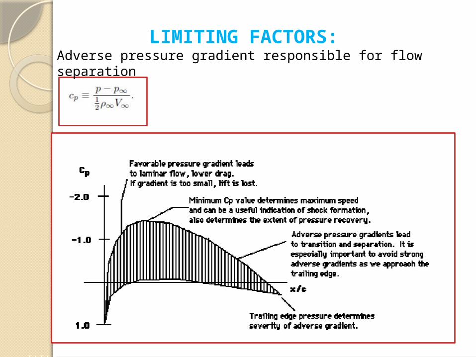
LIMITING FACTORS:Adverse pressure gradient responsible for flow separation

THANK YOU