aircraft operation
TRANSCRIPT

Volume 5
AIRCRAFT OPERATION
Total Control
Table of Contents
PAR
T
SEC
T
CHA
P
TITLE
1 AIRMANSHIP
1 Aircraft Servicing and
Ground Handling
1 RAF MaintenanceOrganization
2 Servicing Documents
3 Ground Handling of Aircraft
4 Airworthiness and AircrewDocumentation
2 Emergencies
1 Aircraft Fires
2 Forced Landing
3 Ditching
4 Distress and Emergency
DO NOT DISTRIBUTE AP 3456
Page 1 : Fri Feb 24 01:26:17 2006 Volume 5 5- 0- 0- 0

Action
3 Escape from Aircraft
1 Aircraft Abandonment
2 Ejection
3 Parachutes and ParachuteDescent
2 FLYING
1 Basic Flying
1 General Flying
2 Take-off, Circuit, Approachand Landing
2A Annex: Aircraft ArrestingSystems for Airfields
3 Stalling and Spinning
2 Advanced Flying
1 Aerobatics
2 Flying in Turbulence
3 Flying at High Speed/Altitude
4 Low Flying
5 VTOL/STOL
6 Formation Flying
6A Annex: Standard FormationHand Signals
7 Air-to-Air Refueling
8 Asymmetric Flight andEngine-out Performance
9 Instrument Flying
9A Annex: Aircraft Icing
10 Night Flying
10A Annex A: Surface Lighting
10B Annex B: Aircraft ExternalLighting
11 Airways Flying Procedures
12 Airborne Early Warning(AEW) and Airborne Warningand Control Systems(AWACS)
3 Helicopter Flying
1 Helicopter Flying Techniques
2 External Load Carrying
3 Tropical and Cold WeatherOperation
3A Annex: Helicopter Icing
4 Mountain Flying
DO NOT DISTRIBUTE AP 3456
Page 2 : Fri Feb 24 01:26:17 2006 Volume 5 5- 0- 0- 0

5 Shipboard Operations
6 Search and Rescue (SAR)Operations
AIRMANSHIP
Aircraft Servicing and Ground Handling
Chapter 1 - Royal Air Force Maintenance Organization
Introduction
1. The objective of the maintenance organization in the RAF is to maintain, in the most effective manner, aircraft and othertechnical equipment in a fit condition to fulfil their intended purposes. Other than aircraft, this applies to avionics systems, aircraftassisted escape systems, survival equipment, weapons, flight simulators and synthetic trainers, ADGE and SAM systems,communications and control systems, MT, and the ground test and training equipment used to support them, including operational orsupport software.
Maintenance Policy
2. The maintenance policy of the RAF is based upon a judicious balance of preventive and corrective maintenance. A policy overlyweighted towards preventive maintenance could result in low utilization and over-maintenance. Conversely a policy based entirely oncorrective maintenance could result in unpredictable availability, poor utilization of resources and could give rise to an unacceptablenumber of hazardous or expensive failures.
Maintenance Organization Objectives
3. The objectives of the maintenance organization may be considered under the headings of operational and maintenance objectives.
4. Operational Objectives. The maintenance policy of the RAF has been formulated to ensure that the following operationalobjectives may be achieved:
a. The generation of aircraft and equipment to meet a counter-surprise alert.
b. The support of sustained and intensive flying operations in a NBC and hostile environment.
c. The generation of aircraft, equipment and facilities to meet NATO and National commitments.
d. The satisfaction of relevant contingency plans.
e. The provision of serviceable aircraft and other technical equipment efficiently to satisfy peacetime requirements.
5. Maintenance Objectives. Maintenance policy requires the optimization of preventive and corrective maintenance in order to:
a. Minimize the manpower and resources required.
b. Minimize faults which may result in hazarding an aircraft or causing loss of operational capability or expensive repairs andlengthy downtime.
c. Identify methods for improving reliability and maintainability.
DO NOT DISTRIBUTE AP 3456
Page 3 : Fri Feb 24 01:26:17 2006 Aircraft Servicing and Ground Handling 5- 1- 1- 1
Preventive Maintenance
6. Preventive maintenance is carried out to reduce the probability of failure, to restore the inherent level of equipment reliability andto ensure that performance is not degraded by time or usage. Within the RAF it comprises four types of maintenance:
a. Servicing. Servicing is the maintenance required by an aircraft or other item of equipment after a period of use and itspreparation for the next period of use. It involves the checking and replenishment of consumables and examination for obvioussigns of unserviceability.
b. Scheduled Maintenance. Scheduled maintenance is carried out at regular, predetermined intervals to keep an aircraft or otheritem of equipment in a sound overall condition and to minimize the amount of corrective maintenance and other day-to-dayattention it requires.
c. Out of Phase Maintenance. Out of phase maintenance is scheduled or condition based maintenance required to be carried outat intervals that do not fit the maintenance cycle.
d. Condition-based Maintenance. Condition-based maintenance is initiated as a result of knowledge of the condition of an itemgained from routine or continuous monitoring. Where condition monitoring is carried out using non-destructive testing (NDT)and Spectrum Oil Analysed Particles (SOAP) techniques, condition-based maintenance is applied to an item in preference toroutine repair or replacement as part of the scheduled or out-of-phase maintenance.
Corrective Maintenance
7. Corrective maintenance is carried out after a fault has occurred in order to restore an item to a serviceable state. Because of therandom nature of fault arisings, the requirements for corrective maintenance cannot be planned, however condition-monitoringtechniques may be used during corrective maintenance to aid the detection of faults.
Modifications
8. Modifications are an integral feature of the overall maintenance policy of an aircraft or other item of technical equipment. Thecosts of embodiment are significant and the down time arising can affect equipment availability. There are therefore detailedprocedures for authorizing and monitoring modifications.
Contingency Maintenance
9. Contingency maintenance is the preventative maintenance considered essential in transition-to-war or war operations whenmaintenance standards are likely to be relaxed and other forms of scheduled and condition-based maintenance are suspended.Contingency maintenance requirements are identified for each aircraft and other items of technical equipment.
Aircraft Servicing and Ground Handling
Chapter 2 - Servicing Documents
MOD FORM 700 SERIES
General
1. The MOD Form 700 is an aircraft maintenance data form which shows the current condition of a specific aircraft. The formconsists of mandatory and specified forms in the MOD Form 700 series, contained within a cover, the MOD Form 700C.
2. An additional cover, MOD Form 700A, Aircraft Log Book, is held by the aircraft’s parent unit in Engineering Records. Itcontains those forms which make up the aircraft’s history and need to be retained for an extended period.
DO NOT DISTRIBUTE AP 3456
Page 4 : Fri Feb 24 01:26:17 2006 Aircraft Servicing and Ground Handling 5- 1- 1- 2

3. All aircrew should be familiar with the layout of the F700C and should have a thorough knowledge of sections which directlyconcern them. The sections of the F700C are described here, with particular emphasis on Section 4 which the captain signs andSection 5 which contains information on the maintenance data system reporting criteria for an aircraft. At the beginning of eachsection instructions for the use of each document in that section are included on the appropriate MOD Form 799.
4. The purpose of the aircraft servicing form is to show whether or not the aircraft is in a fit condition for the operation to which it isassigned. It should be noted that all pages contained within the F700 constitute certificates under Section 50 of the Air Force Act bywhich:
“It is an offence to sign any certificate in relation to an aircraft or aircraft material without ensuring the accuracy of the certificate.”Because of this all entries should be made in ink or ball point pen, and any errors ruled through and initialled.
5. A MOD Form 700 may be carried in its parent aircraft provided that all maintenance documents bearing original signatures forany corrective or preventive maintenance done on the aircraft are removed prior to flight. The MOD Form 799/1(RAF) gives detailsfor the preparation of the F700 prior to carriage in its parent aircraft.
6. During operations away from the parent unit all maintenance documents bearing original signatures are to be returned to theparent unit as soon as possible after the aircraft’s departure from the operating location. The MOD Form 799/1(RAF) details theprocedure for returning such forms to the parent unit.
Section 1
7. Section 1 of MOD Form 700 contains the following:
a. MOD Form 799/1, Index and General Instructions For Use. Produced for each aircraft type, F799/1 provides an index of theforms to be used with that particular aircraft, and the general instructions for their use.
b. MOD Form 701, Leading Particulars. The F701 is produced, as required, by aircraft type. It may contain information on:
(1) Fuels and oils, with alternatives
(2) Basic weight and moment
(3) Tyre pressures
(4) Engine performance data
(5) HUD alignment record
(6) Aircraft dimensions
c. MOD Form 713, Register of Controlled Forms. The F713 is used for registering the insertion and removal of controlledforms. Units are responsible for entering the numbers of the controlled forms detailed on the F799/1 in the Form No column.There may also be forms specified by the Engineering Authority when specialist information is not included on F701
Section 2
8. Section 2 of MOD Form 700 is used to record engineering changes and outstanding work which may affect aircraft operations,and which are required to be brought to the attention of aircrew before they accept the aircraft. The following mandatory forms arerequired:
a. MOD Form 703, Limitations Log. F703 is used to record any faults for which work has been deferred and which affect theoperation or handling of the aircraft in any role the aircraft is expected to undertake.
b. MOD Form 703A List of Modifications, SIs and STIs of Direct Operating Interest to Aircrew. F703A is used to indicate tothe crew the state of modifications, Servicing Instructions (SIs) and Special Technical Instructions (STIs) on the aircraft they areabout to fly, which are of direct interest to them and may not be immediately apparent. Preliminary Warning Instructions and
DO NOT DISTRIBUTE AP 3456
Page 5 : Fri Feb 24 01:26:17 2006 Aircraft Servicing and Ground Handling 5- 1- 1- 2

changes of role are not included.
9. Additional forms specified by the Engineering Authority may include:
a. MOD Form 703, Onboard Software Log. This form may be used when it is necessary to indicate to the pilot the identity ofthe software loaded into the aircraft system(s).
b. MOD Form 703 STF, Special Trials Fits. F703 STF records any special trials fits and any limitations they may impose.
c. MOD Form 703 AE, Avionic Equipment State. This form provides the status of any avionic equipment modificationembodied in the aircraft which has removable components and which may be made inoperative.
Section 3
10. Section 3 of MOD Form 700 details engineering information and outstanding work which does not affect aircraft operations, butneeds to be readily available to engineering personnel. The mandatory form is the MOD Form 704, Annex A, Acceptable DeferredFaults Log. This form is used to record all faults which are considered to be acceptable for flight and which impose no limitation onthe aircraft’s handling or operation.
11. Additional forms which may be specified by the Engineering Authority include:
a. MOD Form 704A, Acceptable Deferred Husbandry Log. This form is used for recording acceptable deferred husbandry.
b. MOD Form 704B. The F704B may be used to record significant engineering changes which affect maintainability, the detailsof which need to be readily available to maintenance personnel. An example of its use is when a permanent repair has beenembodied which affects scheduled maintenance.
c. MOD Form 704C. This series of forms is special to type and has been developed to meet specialist engineering datarecording requirements. Graphical representation is used, where possible, to enhance data capture. An example of a F704C isone used as a record of composite structure repairs for later analysis.
Section 4
12. Section 4 of the MOD Form 700 contains a number of mandatory forms to record and certify:
a. Aircraft or equipment usage.
b. Flight servicing.
c. Replenishment.
13. MOD Form 725, Flying Log and Fatigue Data Sheet. This form is used to record the details of each flight including, whenapplicable, the fatigue meter readings.
14. MOD Form 725A, Air to Air Transactions. F725A is used to record in flight refuelling details.
15. MOD Form 705, Flight Servicing/Fuel Certificate. This form is used for the certifying of flight servicing and fuel states; itcontains the Captain’s after flight declaration and the Captain’s acceptance certificate.
a. The captain’s after flight signature returns the responsibility for the aircraft to the engineering organization and certifiesthat:
(1) He has returned the aircraft to the finally armed state in accordance with the Flight Reference Cards, or that no explosivearmament stores are fitted.
(2) The aircraft assisted escape system safety devices are set to the safe for parking condition.
DO NOT DISTRIBUTE AP 3456
Page 6 : Fri Feb 24 01:26:17 2006 Aircraft Servicing and Ground Handling 5- 1- 1- 2

(3) He has accepted those faults, the serial numbers of work (SNOWs) for which are listed in the “Pre-Flight AcceptedFaults” block against his after flight declaration.
(4) A Maintenance Work Order Log Entry (F707A/ADP) has been raised for each fault that became evident whilst he wasresponsible for the aircraft.
(5) A new F707A (ADP) has been raised for each SNOW listed in the Pre-Flight Accepted Faults block against his afterflight declaration, excepting when the original SNOW is actioned in accordance with F799/5 (RAF) (ADP) for a fault whichwas eliminated before flight but the system was not proved.
(6) The results of any Flying Requirements undertaken have been entered in the F707A (ADP).
(7) When the Station Engineering Management Aid (SEMA) computer is not available, the Flying Log and Fatigue Datasheet (F725) has been completed.
(8) He has indicated whether a pre-flight Command and Stability Augmentation System (CSAS) and Spin Prevention andIncidence Limiting System Built in Test Equipment (SPILS BITE) check was undertaken (Tornado only).
(9) The equipment used blocks, lines 1-3, have been completed (Tornado only).
b. The Captain’s Acceptance Certificate requires the captain to accepts responsibility for the aircraft by signing and printing hisname at lines 27 and 28 after ensuring that the F700 Co-ordinator has signed the Flight Services Certificate at line 24.
NOTE:When a NATO Cross Servicing has been undertaken, the captain is to undertake the actions of the F700 co-ordinatorand strike through any unused lines).
The captain’s acceptance signature certifies that:
(1) Where a SNOW appears in the Flying Requirements block he has obtained the nature of the requirement from the F707A(ADP).
(2) He is aware of the Modification, SI, STI state shown on the F703A and the Special Trials Fit shown in the F703STF.
(3) The Fuel and Role states are as required.
(4) He accepts the Limitations recorded on F703.
(5) He accepts the Aircrew Accepted Faults identified by SNOW in the Aircrew Accepted Faults block.
(6) He has ascertained from the CSAS/SPILS BITE whether a CSAS/SPILS BITE check is required (Tornado only).
When an aircraft captain elects to accept a fault during turnaround or operational turn around by signing the Aircrew Accepted blockon the relevant Maintenance Work Order Log entry, the F700 co-ordinator is to enter the SNOW of that Work Order in the AircrewAccepted Faults block of the next Captain’s Acceptance Certificate block.
16. MOD Form 724, Flying Log and Equipment Running Log. This form is for rotary wing aircraft and is used to record flightdetails and running data of specified equipment.
17. MOD Form 705 (SSR), Supplementary Flight Services Register. F705 (SSR) is a register of all maintenance activities requiredto be undertaken in conjunction with flight servicing.
18. MOD Form 705 (SSC), Supplementary Flight Servicing Certificate. This form complements the Supplementary Flight ServicesRegister and is used to certify completion of the maintenance activities done in conjunction with flight servicing.
DO NOT DISTRIBUTE AP 3456
Page 7 : Fri Feb 24 01:26:18 2006 Aircraft Servicing and Ground Handling 5- 1- 1- 2

19. MOD Form 706B, Fuel Uplifts Not Containing Fuel System Icing Inhibitor (FSII) or Lubricity Additive. F706B is mandatoryfor all aircraft which use aviation turbine fuel, and is used to record uplifts of fuel not containing FSII and/or Lubricity Additive. Itcan also be used to maintain, when required, a permanent record of each engine fuel pump’s cumulative running hours on fuel notcontaining Lubricity Additive.
20. Additional forms in Section 4 which may be specified by the Engineering Authority are:
a. MOD Form 706, Role Equipment and Expendable Stores States.
b. MOD Form 726, Equipment Running Log.
c. MOD Form 705HB(H), Helicopter Ground Running Flight Servicing Certificate.
d. MOD Form 737, Oil Replenishment and Sampling Record.
e. MOD Form 737A, Oil Replenishment Record. This form is used when the aircraft or component is not subject to SpectrumOil Analysed Particles (SOAP) procedures.
Section 5
21. Section 5 of the F700 includes a number of mandatory forms used for registering all corrective and preventive maintenance,excluding flight servicing, required on an aircraft. It also contains information on the Maintenance Data System (MDS) reportingcriteria and codes.
23. MOD Form 799/5A(RAF) (ADP) Instructions for Use - Aircraft Maintenance. This form provides instructions for raising amaintenance work order (MWO) from an entry in F707A(ADP). It contains MDS reporting criteria for corrective and preventivemaintenance.
24. Additional forms in Section 5 specified by the Engineering Authority may include the following:
a. MOD Form 799/5R, MDS Reporting. New aircraft types report all corrective maintenance and no F799/5R is issued. As theaircraft progresses through its Service life, the level of reporting may change as required by the Engineering Authority andF799/5R is then raised. There are four levels of reporting below full reporting; these are reduced, limited, minimum and nil.
b. MOD Form 705B. This form provides for aircrew to record engineering information while the aircraft is under their control.Any instructions for use will be included on the form.
Section 6
25. Section 6 of MOD Form 700 may contain forms used in forecasting scheduled and out of phase maintenance. There are nomandatory forms for Section 6 of F700. The Engineering Authority specified forms may include the following:
a. MOD Form 721B, Forecast Sheet. This form provides a summary of all maintenance and component replacements dueduring a specified period. The Summary is extracted from the Maintenance and Component Replacement Control Document (M& CRCD) in F700 Section 7. Using the forecast sheet, the F700 Co-ordinator is permitted to declare an aircraft fit to fly withoutrecourse to the M & CRCD provided no limits shown in the “Forecast Limits Block” have been exceeded.
b. MOD Form 721C, Flexible Primary Maintenance Control Chart. This form is used for planning and controlling flexibleprimary maintenance.
c. MOD Form 723 WL, Forecast Log - Winch Lifts Remaining. The standard forecast logs are unsuitable for forecasting winchmaintenance and F723WL has been provided for this task.
Section 7
DO NOT DISTRIBUTE AP 3456
Page 8 : Fri Feb 24 01:26:18 2006 Aircraft Servicing and Ground Handling 5- 1- 1- 2

26. Section 7 of MOD Form 700 Contains the Maintenance and Component Replacement Control Document (M & CRCD) and isused to control and forecast scheduled and out of phase maintenance. It also provides data for the completion of maintenancedocuments. Where the Engineering Authority specifies the use of F721B, Section 7 is to be maintained in a separate F700C coverand held by the engineering organization responsible for the aircraft. The functions of the M & CRCD are provided in full by theStation Engineering Management Aid (SEMA) computer system.
27. There are no mandatory or Engineering Authority specified forms; the forms used depend on the content of the aircraft’s masterservicing schedule (Topic 5A1). Those available are:
a. MOD Form 798, Instructions for Use. This form provides detailed instructions for the M & CRCD and all other formsdescribed in this section.
b. MOD Form 798B, Amendment Record.
c. MOD Form 728, Component Replacement Record.
d. MOD Form 728A, Component Replacement Record - High Frequency Items.
e. MOD Form 728X, Explosive Component Replacement Record.
f. MOD Form 727E, Schedule and Out of Phase Maintenance Register.
g. MOD Form 727C, Supplementary Maintenance Register.
h. MOD Form 727D, Supplementary Maintenance Record.
i. MOD Form 709A, Forecast Log - Calendar.
j. MOD Form 723/1 to 723/4, Forecast Logs.
Other Sections
28. Sections 8 to 12 of MOD Form 700 cover such topics as Engine running data, weight and balance, nuclear weapons installationsand various pod systems.
Aircraft Flying Times
29. Recorded flying times for an aircraft are the periods the aircraft is reckoned to be airborne, and do not include time spent on theground with engine(s) running between sorties. Flying times are recorded in the MOD F700 and Engineering Record Cards (ERCs),and are used as the basis for calculating the periodicity of maintenance activities and equipment reconditioning when these depend onthe hours flown.
Aero-engine Running Times
30. The running times of engines fitted with elapsed time indicators (ETI) are taken as indicated on the ETI. In other cases the timerun by an aero-engine is reckoned from the flying time of the aircraft in which the engine is installed and does not include the timerun on the ground for any purpose. Engine running time is recorded in the MOD F700 and the ERCs for that engine, and is used tocalculate the periodicity of relevant maintenance activities and equipment reconditioning. The time run by an aero-engine on a testbench following manufacture, reconditioning or repair is not taken into account for the purpose of calculating maintenance ofreconditioning periodicity, and is not recorded on ERCs.
Helicopter Transmission Components
31. The time run by helicopter transmission components, rotor heads and rotor blades is reckoned as for aircraft flying times as inpara 30 above.
MAINTENANCE DATA SYSTEMS
DO NOT DISTRIBUTE AP 3456
Page 9 : Fri Feb 24 01:26:18 2006 Aircraft Servicing and Ground Handling 5- 1- 1- 2
General
32. The computer based maintenance data system (MDS) is used to collect and analyse maintenance data both for the RAF and theFleet Air Arm. The MDS is able to provide information rapidly and accurately on defects and provide information on servicing workdone. Access to this information enables managers to obtain better reliability and to make best use of servicing resources. Thesystem comprises six major data elements, each concentrating on one particular aspect of maintenance data, although havingconsiderable interdependence. The elements are faults, modifications, manpower utilization, task achievement, technical costs andlogistics. The faults or defects element provides a wide range of routine and ad hoc outputs for the support of engineering analysis,survey, and review. Aircraft fatigue monitoring is also undertaken, and units and engineering authorities can be supplied with fatigueindex information on floppy disks to assist fleet management.
33. The Engineering Information Centre maintains a computer indexed centralized bank of engineering information, narrative datafrom MOD Form 760 series documents, incident/accident reports and other engineering reports. Abstracts or detailed information areavailable on request. The Engineering Information Centre also maintains a record of all modifications and technical instructionsauthorized and issued on microfiche.
MOD Form 707/720 Document Relationship - Maintenance, Analysis & Computing Department(MACD) Reporting Loop
34. One of the functions of MDS is to trace the chain of events between the MACD reportable occurrence being discovered and thefault being eliminated. A symptom may be eliminated by the replacement of a component, but it is important that the fault within thereplaced component is identified and recorded. This information may not become available until the component is tested ordismantled at another work centre, such as a bay or Maintenance Unit. The linking of records of work done on the faulty componentat the various levels of maintenance is known as the MACD Reporting Loop. The MDS monitors the reporting loop through anOriginators Reference Number (ORN) which is a unique reference made up from Unit, Serial Number of Work (SNOW), the aircrafttail number and the date. Whenever the symptom of a reportable occurrence is discovered (unless the component has previously beenreported to MACD), the occurrence is reported on MOD Forms 707B(ADP), 720K(NCR) or 720Q/1 as applicable, and given anORN. If the component has been reported to MACD previously, all subsequent faults are actioned as supplementary non-relatedfaults. If the fault is completely eliminated at this stage or if the faulty component is scrapped, the fault repair chain goes no furtherand the loop is started and finished on the Forms 707B(ADP), 720K(NCR) or 720Q/1. If the faulty component is passed to anotherwork area for repair or investigation the work done at the second area is recorded on a supplementary MOD F 707B(ADP),720K(NCR) or 720Q/1. All further work areas use the same recording method; the documents are related by the same ORN, andMDS receives all the reports. The ultimate cause of the fault can therefore be traced irrespective of the number of work areasinvolved in an investigation. The medium for transferring the fault information and the ORN from one work area to the next is theMOD Form 731 equipment label, attached to the faulty component.
35. If more than one component is replaced in a single occurrence the MOD Form 707J(ADP) A11 is used to inform MDS thatcomponents in addition to the one reported in F707B(ADP) have been changed to eliminate the fault. The A11 carries the same ORNas the F707B(ADP).
MOD Form 725 - Flying Log and Fatigue Data Sheet
36. The MOD Form 725 Flying Log and Fatigue Data Sheet is used to record details such as aircraft weight and stores configuration,the stores weight of an individual flight, and where applicable, fatigue meter readings, for subsequent calculation of component andaircraft fatigue life consumption. The F725 is designed to suit the requirements of a particular aircraft and there are threeformats:
a. Non ADP. The non ADP format is used for aircraft having no requirement for ADP fatigue processing.
b. ADP. The ADP format is the most common. The form is broken down into data blocks which are designed for easycompilation and computer input.
c. Single Sortie. The single sortie format is designed to be a standby document for when SEMA is not available. There is onlyone sortie’s data on each sheet.
DO NOT DISTRIBUTE AP 3456
Page 10 : Fri Feb 24 01:26:18 2006 Aircraft Servicing and Ground Handling 5- 1- 1- 2

MACD Data Services
37. The MACD data services available are:
a. Interrogation and analysis of maintenance data derived mainly from the F707(ADP) Maintenance Work Order (MWO) andF720 series of work cards in respect of RAF and RN aircraft and equipment.
b. Interrogation and analysis of fatigue data derived from F725 Flying Log and Fatigue Data Sheets in respect of specific RAFand RN aircraft types.
c. Interrogation of information contained on fault investigation and overhaul reports.
d. Provision of information abstracted or derived from engineering reports, modification leaflets, servicing instructions etc.
e. Provision of periodic reports indicating existing or potential problem areas, reliability trends and costs in terms of man-hours,operational effects or equipment shortages.
f. Identification of alternative NATO Stock Numbers, Section/Reference Numbers and Part Numbers for items of equipment,utilizing the MACD database catalogues.
MACD Outputs
38. The MACD data services outputs depend upon the form of enquiry.
a. Ad Hoc. The output in response to an ad hoc enquiry may be a simple narrative reply, a print out of the data beingconsidered, and/or a graphical presentation of the interrogation results.
b. Fixed Format. Fixed format outputs provide a statistical view of a particular aircraft fleet, equipment type or component.They are categorized as:
(1) Routine. Routine outputs are of fixed format, issued at a set periodicity to a fixed distribution list.
(2) Standard. Standard outputs are of fixed format and issued on request.
(3) Recurring. Recurring outputs are of fixed format designed by the sponsor and issued at regular intervals according to therequirements of the sponsor.
c. Special Studies. Special studies may be undertaken on behalf of an engineering authority (EA) or other authorities. Thereports may utilize all the maintenance data available to MACD.
d. Abstracts or Copies. Abstracts from or copies of engineering reports, modification leaflets, etc are provided in printed formor on microfiche cards as requested.
Aircraft Servicing and Ground Handling
Chapter 3 - Ground Handling of Aircraft
Introduction
1. This chapter provides information on those aspects of aircraft ground handling with which aircrew should be familiar. Thevarious topics are covered in general terms since particular circumstances and local requirements may, from time to time, necessitateminor amendments.
GROUND HANDLING
DO NOT DISTRIBUTE AP 3456
Page 11 : Fri Feb 24 01:26:18 2006 Aircraft Servicing and Ground Handling 5- 1- 1- 3

Seeing In and Seeing Off
2. Aircraft arrivals and departures are usually attended by a handling team comprising two tradesmen.
3. On arrival the handling team will marshal the aircraft into a designated parking area which has been cleared of foreign objectsand non-essential items of ground equipment. When signalled by the aircraft captain chocks are inserted and ground power and anynecessary ground servicing equipment is connected. Fire extinguishers are positioned and manned as required during engineshut-downs, aircraft steps are positioned and the aircrew are assisted with unstrapping. Finally the handling team will fit safetydevices, covers and blanks.
4. Appropriate actions are carried out in the reverse order for departure.
Marshalling
5. The aim of the marshaller is to assist the pilot in the safe manoeuvring of the aircraft on the ground. The signals used arestandard throughout the RAF and are illustrated in JSP 318, annexes 051A and 051B.
6. The need for marshalling assistance will be governed by the pilot's familiarity with the airfield, the number of obstructions, thesize of the aircraft and the field of view from the cockpit. At an unfamiliar airfield taxiing instruction can be passed by radio andoccasionally "follow me" vehicles may be used.
7. Marshalling Procedure - Day. Marshallers should identify themselves to pilots by energetic waving of the arms in a circularmotion. The marshaller may wear clothing of a distinctive colour as an aid to identification. The type of marshalling will vary withcircumstances - to park an aircraft in a particular position when the approaches to it are clear, requires only that the pilot is given anindication of the position where it must finally be stopped. This information should be given to the pilot as soon as possible by themarshaller standing on the required spot with his arms outstretched, facing towards the final position of the aircraft. The pilot is thenfree to taxi the aircraft in a path of his own choosing to the position indicated. If obstructions exist, two extra personnel may berequired to complete the marshalling team. They should walk on either side of the aircraft, ahead of the wing tips and signal to thepilot if there is sufficient clearance for the aircraft to pass. This assistance is most likely to be necessary when marshalling largeaircraft with restricted fields of view from the cockpit.
8. Marshalling Procedure - Night. While taxiing at night in congested areas, detailed marshalling directions are necessary, althoughthe need is less if taxiing lights are used. If dispersal areas are floodlit, marshalling assistance can be reduced to that given indaylight. Navigation lights should always be on and taxi lights should be used although care should be taken not to dazzle themarshaller. Marshallers should be in a position where they can be seen by the pilot at all times, identified by wands or torches. Theaircraft should be stopped if the pilot loses sight of the marshaller.
9. Division of Responsibility. The pilot is responsible for the safety of the aircraft and is not required to comply with marshallinginstructions considered to be unsafe; he is at liberty to pursue the course of action he thinks best.
Chocks, Safety Devices, Blanks and Covers
10. Whenever aircraft are shut down and stationary on the ground, and during engine runs, they should be securely chocked. Safetydevices, blanks and covers should be fitted throughout the time that the aircraftis shut down, unless removed temporarily formaintenance.
Danger Zones
11.
a. General. Danger zones are those areas in which there is a high risk of injury to personnel when aircraft components orsystems are operated on the ground. Normally they comprise areas around engine intakes and exhausts, including auxiliarypower units, propellers and helicopter rotors. In particular piston-engined aircraft propellers should always be considered "live"and should only be swung as directed and in accordance with approved procedures. Special care is necessary when in closeproximity to a helicopter in gusty wind conditions when blade sailing may bring rotor blades close to the ground.
b. Slipstream/Jet Efflux. Even when the engine is idling, a propeller slipstream or the efflux of a jet engine can be powerful
DO NOT DISTRIBUTE AP 3456
Page 12 : Fri Feb 24 01:26:18 2006 Aircraft Servicing and Ground Handling 5- 1- 1- 3
enough to damage loose items of ground equipment or any other foreign objects. Personnel must be aware of such hazardsparticularly during engine start-up and initial taxying and take care to prevent such dangers.
Wheel and Brake Fires
12. There is a danger of explosion if rapid and uneven cooling of an aircraft wheel or brake assembly should occur. The safestcourse of first-aid action against an aircraft wheel or brake fire is:
a. To stand forward or rearward of the wheels depending on the prevailing wind, but never in line with the axle.
b. To operate the fire extinguisher at the limit of its range to spray the extinguishant downwards towards the wheels, ensuringthat the flow strikes the ground 0.3m away from the wheels and flows onto the wheels.
REFUELLING
Fuels
13. Aircrew may have to supervise the refuelling of their aircraft, therefore the following paragraphs are included in order that therelevant information may be studied.
14. AP 3456 Vol 2, Part 1, Sect 7, Chap 1 deals in some detail with aviation fuels. In general terms the following types are inregular use:
a. AVGAS - aviation gasoline.
b. AVTUR - aviation turbine fuel (kerosene).
c. AVTAG - aviation turbine widecut gasoline.
d. AVCAT - aviation turbine fuel, used largely by the Royal Navy.
AVGAS is divided into two grades, that used for a particular engine being determined by the compression ratio and maximummanifold air pressure rating of the engine, the operational role in which it is employed, and the geographic locality in which it is used.The use of AVTUR or AVTAG in turbine engines is usually determined by the design specification of the engine. The majority ofgas turbine engines may be run on either of these subject to certain precautions and limitations as detailed in the Aircrew Manual.
Lubricating Oils
15. Lubricating oils of different viscosities are used for reciprocating engines and gas turbine engines, the gas turbine requiring anoil of very much lower viscosity. The various grades are distinguished by the letters, NATO code numbers and colours superimposedas appropriate on the containers (Fig 1).
Identification
16. With so many fuels and oils in common use, great care is necessary to ensure that aircraft are replenished with the correct gradeand type. Aircraft filler caps are identified by a red 300 mm diameter circle with AVGAS in white letters, or a black 300 mm squarewith AVTUR in white, as appropriate. Refuellers are also clearly marked with the grade and colour code of the fuel they contain. Allfuels are given a full joint service nomenclature and a recognized abbreviated designation. Lubricants are also allotted symbols bywhich they are known in all three Services and most fuels and lubricants have a NATO code number for ease of cross-servicing.
Refuelling Appliances
17. Bowsers. A mobile bowser in its various forms is the normal conveyor of fuel from storage tanks to aircraft. There are severaltypes but the purpose and layout is basically the same. Fuel is pumped through delivery hoses by the vehicle's main engine or a smallauxiliary engine housed at the rear of the bowser. Handling instructions for the auxiliary engine are usually printed on the inside of
DO NOT DISTRIBUTE AP 3456
Page 13 : Fri Feb 24 01:26:18 2006 Aircraft Servicing and Ground Handling 5- 1- 1- 3

the housing doors.
5-1-1-3 Fig 1 Fuel and Oil Identification Markings
18. Portable Fuel Tanks. Portable fuel tanks of varying capacities are sometimes used in conjunction with mechanical or handpumps for refuelling aircraft when a bowser is not available. Such a combination might be used to refuel when operating from atemporary base.
Refuelling Precautions
19. Adequate fire fighting equipment must be readily available before aircraft refuelling is commenced. The risk of fire duringrefuelling is a very real one which can be minimized by the application of the following simple precautions:
a. When refuelling from a vehicle the danger of a spark caused by static electricity should be avoided by bonding the refuellingvehicle and delivery nozzle to the aircraft and the refuelling vehicle to earth.
b. Spillages of fuel can spread a fire over a large area and should be avoided; any spillage should be washed away by a firetender.
c. Refuelling and defuelling in a hangar or with engines running is not permitted unless specially authorized.
d. Refuelling crews should not carry cigarette lighters or non safety matches and they should, whenever possible, wear rubber orcrepe soled footwear.
e. Flame proof torches should be used and no naked lights should be permitted within 30m of any refuelling or defuellingoperation.
f. Work on electrical or radio equipment, including R/T transmissions, should not be conducted whilst refuelling is in progress,or within 15m of an aircraft which is being refuelled.
g. Refuelling should not be carried out within 40 m of an aircraft with engines running.
h. Refuelling vehicles should be positioned so that they can be quickly moved in the event of a fire. Bowser trailers should notbe disconnected from their prime mover during refuelling operations.
Finally, as a general precaution when filling oil tanks, adequate air space should be left for expansion and frothing of oil when heated.All filler caps should be checked for correct fitment following replenishment.
DO NOT DISTRIBUTE AP 3456
Page 14 : Fri Feb 24 01:26:18 2006 Aircraft Servicing and Ground Handling 5- 1- 1- 3

Pressure Refuelling
20. The basic difference between the system for pressure refuelling on the ground and that for use in flight is the position of thefilling point. For either system all tanks or tank groups are fitted with shut-off valves, mechanically or electrically operated. Thevalves give positive fuel shut-off at the desired level, with pressure relief arrangements to protect the aircraft fuel lines. Importantprecautions to be taken when pressure refuelling are to ensure that the refuelling coupling is correctly connected, that bonding iscomplete, aircraft switches are correctly set and that the maximum refuelling pressure is not exceeded.
Aircraft Servicing and Ground Handling
Chapter 4 - Airworthiness and Aircrew Documentation
Introduction
1. The purpose of this Chapter is to define and highlight key areas of airworthiness as it affects the operator; a working knowledge ofwhich is essential for the safe and efficient conduct of flight. Reference to JSP 318, Military Flying Regulations, and JSP 318B,Regulation of Ministry of Defence Aircraft, is made where appropriate.
2. Detailed rules for the operation of Service aircraft and for the maintenance of flying discipline are issued by the Ministry ofDefence. Such rules will comply with the overall policy laid down by the Ministry of Defence both for aircraft operations generally,and for the individual aircraft, weapons, or other airborne equipment. These rules have taken engineering and operating aspects ofairworthiness and flying regulation into account (JSP 318B 1.20).
Airworthiness
3. Airworthiness is defined as the ability of an aircraft or other airborne equipment, or system, to operate without significant hazardto aircrew, ground crew, passengers or to the general public or friendly military personnel over which the aircraft is flown.Airworthiness is not only concerned with engineering aspects (Engineering Airworthiness), but also with the way an aircraft is flownand how its systems are operated (Operational Airworthiness) (JSP 318B p3).
Military Aircraft Release
4. The Ministry of Defence Military Aircraft Release (MAR) is the statement of the operating envelope, conditions, limitations, buildstandard and procedures within which the airworthiness of the design has been established. Usually, it is the product of considerableeffort from industry, test pilots, and supporting engineering staffs to delineate Service use and the limits to which the aircraft may besafely flown in Service (JSP 318B p11).
Release-to-Service
5. The Release-to-Service (RTS) is the definitive document containing the operating limitations for aircraft and other airbornesystems, and equipment, in Service-regulated flying. The RTS is founded upon the current standards of MAR, and can besupplemented with Service Deviations (SD) and explanatory notes (JSP 318B p18).
Service Deviations
6. A Service Deviation is a permitted deviation from the conditions of the MAR for the purpose of Service-regulated flying. SDs areusually delineated as follows:
a. Category 1 SDs are authorized by the Service operations branch to permit flight outside the established RTS limitations.
b. Category 2 SDs, which pertain to operations carried out within the limitations of the RTS, are authorized by the Serviceoperations branch or the Engineering Support Authority for the aircraft (JSP 318B p19).
DO NOT DISTRIBUTE AP 3456
Page 15 : Fri Feb 24 01:26:18 2006 Aircraft Servicing and Ground Handling 5- 1- 1- 4
Aircrew Manuals
7. Aircrew Manuals (AM) used by aircrew are published by the Royal Air Force Handling Squadron to inform and define aircraftsystems, operating drills and limitations. The Manuals, and their associated Flight Reference Cards (FRCs), are live documentsconstantly under review and amendment as Service modifications and experience of type grows. Liaison between Handling Squadronauthors, aircraft manufacturers, support authorities, trials units and front-line crews enables the best available technical and operatingadvice to be provided. In terms of flight safety and the legal obligations of operational airworthiness the AM is a part of theAirworthiness Document Set for the aircraft. FRCs are an integral part of the AM for the aircraft concerned (JSP 318B p3). The AMis complementary to the RTS, FRCs and associated Operating Data Manual (ODM).
8. The limitations quoted in the AM (unless over-ridden by the RTS) are mandatory and are not to be exceeded except in recoveringfrom emergency situations as covered at para 15. Any infringement of limitations is to be formally reported in accordance with localprocedures. Other information within the AM is advisory but instructions containing the words 'is to' and 'are to' are alsomandatory.
9. The AM, and its associated FRCs, aim to provide the best operating instructions and advice currently available. Although theyprovide guidance for most eventualities, they are not substitutes for sound judgement and good airmanship; moreover, they assume anadequate knowledge of the pertinent volumes of AP3456. Furthermore, circumstances might require aircrew to depart from or modifythe prescribed procedures and drills. Consequently, the AM and FRCs should not be regarded as immutable, and operators areencouraged to pass observations or suggestions to Handling Squadron through respective standards squadrons.
Flight Reference Cards
10. FRCs are an aide mémoire containing definitive checks and drills for normal and emergency operation of the aircraft and itssystems and are designed to be used by aircrew in flight. In terms of flight safety and operational airworthiness the FRCs are a part ofthe Airworthiness Document Set for the aircraft. The FRCs are complementary to the RTS, AM and associated ODM (JSP 318B p3).
Operating Data Manual
11. The ODM provides definitive performance definitions and data on the aircraft concerned for aspects such as take off, climb,manoeuvre, descent and landing. This information is normally presented in the form of performance graphs which are used byaircrew in planning the flight concerned. In terms of flight safety and operational airworthiness the ODM is a part of theAirworthiness Document Set for the aircraft (JSP 318B p14).
Advance Information Leaflets
12. Advance Information Leaflets (AIL) are issued to promulgate new information to AM quickly when a modification changes theoperating procedure, introduces a new piece of equipment, or when operating procedures are to be changed and need to be explainedurgently. Action can be initiated as a result of activities at Design Authority, Special Trial Instructions, Service EngineeredModifications and the like, but AILs are not normally used if the new information can be included in a routine amendment insufficient time. AILs are not used for FRCs.
Advance Notification of Amendments Procedure
13. An Advance Notification of Amendments Procedure (ANA) is used to disseminate rapid amendments to FRC, AM and ODM.ANA are normally issued by signal and generally will take the form of a manuscript amendment, which will be incorporated in thenext formal amendment.
Special Flying Instructions
14. Special Flying Instructions are issued to notify aircrew urgently of important changes to the way in which aircraft or theirequipments are to be operated (JSP 318 02005).
Aircraft Limitations
15. Normal Limits. Flying must be planned so that the engine, airframe or handling limitations quoted in the RTS will not beinfringed in Service-regulated flying (JSP 318 00403). The limitations are reflected in the AM, FRC and ODM, and are not to be
DO NOT DISTRIBUTE AP 3456
Page 16 : Fri Feb 24 01:26:18 2006 Aircraft Servicing and Ground Handling 5- 1- 1- 4

exceeded except under specifically controlled and permitted conditions, or as circumstances dictate during combat, emergency orhumanitarian missions (JSP 318B 2.1). If the limitations are exceeded at any time, or if the aircraft has been subjected to abnormalstress or strain in the air or on the ground, the pilot is to report the fact on the Form 700 for the aircraft, and to his authorizing officer,as soon as possible.
16. Transient Limits. Except in an emergency, or unless specifically defined in an aircraft's RTS, flights should not be planned tomake deliberate use of quoted transient limits. When a transient area of operation is encountered, action must be taken to returnwithin normal limits without delay.
Emergencies
Chapter 1 - Aircraft Fires
Introduction
1. Precautions against fire are design requirements for all aircraft and these, together with the development of safety devices andextinguisher systems, have reduced this risk to all aircraft operations.
2. Aircrews should familiarize themselves with appropriate:
a. Fire warning and extinguisher systems.
b. Actions to be taken in the event of fire.
c. Layout of the electrical, hydraulic, pressurization and fuel systems.
d. Position and operation of aircraft fire-fighting equipment.
e. Main structural details of the aircraft.
Fire Warning
3. Engine Bay Fires. Visual indication of engine fires may not be immediate because of the position of the engine. Fire warningsare actuated by fire detectors on the engine bays and are passed to aircrew by the illumination of red fire warning lights in the cockpitor on the flight deck, usually accompanied by an audio warning. Fire warning lights are usually part of a central warning panel. Inthe event of a crash-landing the engine extinguisher systems of most aircraft, if fitted, are actuated automatically by the crashswitches.
4. Fuselage Fires. Normally, adequate fire warning is given of fuselage fires by the presence of smoke, a little of which can quicklyfill a cockpit flight deck or cabin. On some aircraft it may be possible to open cockpit or flight deck windows, but opening windowsmay cause an induced forward draught which could encourage smoke to fill the area; windows should therefore be kept closed untilthe fire is out, when they may be opened to remove toxic fumes. As well as extinguishing the fire the crew should carry out the FRCdrill for smoke or toxic fumes.
5. Fuel Tank Compartment Fires. Some aircraft have a separate, automatic fire warning system for each fuel tank compartment,with fire warning being given by means of an illuminated red warning light in the cockpit. Few fighter type aircraft have provision forextinguishing fuel tank compartment fires, but a warning light in the cockpit warns the pilot that he must prepare to abandon theaircraft. If the fire indication has been given only by a glowing warning light, the pilot should reduce power and speed as quickly aspossible and carry out the appropriate fire drill. At the same time he should try to ensure that a fire has, in fact, occurred. If thewarning light continues to glow but no other indication of fire is present, the flight should be continued at reduced power and alanding made as soon as practicable. Action to be taken is invariably indicated in the appropriate Aircrew Manual.
6. Electrical Fires. Electrical fires are usually caused by arcing or short circuits and may affect almost any part of the aircraft. Acommon symptom of an electrical fire is the presence of pungent smoke in the cockpit. FRC drills should be carried out in order to
DO NOT DISTRIBUTE AP 3456
Page 17 : Fri Feb 24 01:26:18 2006 Emergencies 5- 1- 2- 1

isolate the faulty equipment and to clear any smoke.
FIRE IN THE AIR
General Considerations
7. On receipt of a fire warning, or on visual observation of a fire, the captain should warn the crew and initiate the FRC fire drill.Should the fire show no signs of abating after completion of the drill, or if there is a risk of explosion or structural failure, the captainshould give orders to abandon the aircraft, if height permits, rather than attempt a forced landing. Landing with the aircraft on fire isseldom justified and very dangerous; there is little chance of saving the aircraft after landing and there is a great risk that the fire mayincrease or cause structural failure at an altitude where it would be unsafe to abandon the aircraft.
Fire Drill for Piston and Turboprop Engines
8. An engine fire is most commonly a fuel or oil fire. The supply of fuel and, if possible, oil should be shut off, the engine stoppedand the propeller feathered. Although the fire may be checked by operating the fire extinguisher, if fitted, as soon as the brief actionof the fire extinguisher is finished, the fire is liable to recur if the engine is still running. To obviate the presence of unburnt gases theignition should not be switched off until the engine has stopped or nearly stopped; the fire extinguisher should then be operated.
9. Detailed drills will be found in the Aircrew Manual and FRC for a particular aircraft type but, in general, if the propeller can befeathered the engine should be stopped by closing the throttle, feathering the propeller and turning off the fuel and oil supply to theengine. When the engine has stopped the ignition should be switched off and the fire extinguisher operated if fitted. The toxic fumeshazard can then be dealt with by setting the oxygen regulator to emergency and turning off any cockpit air supply from the enginebay.
10. If the propeller cannot be feathered the throttle should be closed and the rpm control moved to the minimum position. The fuelsupply should then be turned off and, when the propeller has slowed to minimum rpm, the ignition should be switched off and the fireextinguisher then operated. The oxygen regulator should then be set to emergency and any cockpit air supply from the engine bayshould be turned off to prevent the entry of fumes.
Fire Drill for Turbojet Engines
11. The principles applied to piston engines are also applicable to turbojet engines. The throttle should be closed and fuel turned off,speed reduced as quickly as possible and the fire extinguisher then operated. The oxygen regulator should then be selected toemergency and any air supply from the engine should be turned off. Detailed drills are covered in the Aircrew Manual and FRC.
Fire Drill for Fuselage Fires
12. Prompt action by the crew, using hand-held fire extinguishers, will normally successfully combat fuselage fires. Hand-held fireextinguishers fitted to most aircraft contain either a halocarbon agent, usually an inert gas, or a water/glycol mixture. Halocarbonscan be used against any type of fire and have been introduced to replace halon agents which are being gradually withdrawn forenvironmental reasons. Water/glycol extinguishers are non toxic and must not be used on burning or flammable liquids or firesinvolving electrical equipment. All high voltage radio and radar equipment should be switched off, if possible, before this type ofextinguisher is used. Further details are given in Vol 6, Pt 1, Sect 1, Chap 6.
Restarting Engines
13. No attempt must be made to restart an engine after an engine bay fire has been successfully extinguished. The fire is liable torecur if the engine is restarted and the fire extinguisher system will not act again until replenished.
Accidental Operation of Fire Extinguisher System
14. If an engine bay fire extinguisher is accidentally discharged the engine should be operated according to the advice given in theAircrew Manual. If an extinguisher using methyl bromide or, any other chemical having a toxic nature, is discharged inside theaircraft, the toxic fumes drill should be carried out immediately.
DO NOT DISTRIBUTE AP 3456
Page 18 : Fri Feb 24 01:26:18 2006 Emergencies 5- 1- 2- 1

15. The operation of fire extinguishers, accidental or deliberate, must be reported after landing so that the necessary action can betaken to minimize corrosion and fouling, and to replenish the extinguisher system.
FIRE ON THE GROUND
General
16. A fire on the ground may start during refuelling, on engine start-up, and during routine testing and servicing. In addition wheelbrakes may become excessively hot during the landing run or when taxiing and cause a fire.
Refuelling/Defuelling and Starting Precautions
17. Generally during refuelling and defuelling, only those electrical services necessary for the operation (eg electrical fuel contentsgauges) should be selected - no other electrical service (including radio and radar) should be operated. Fuel contents gauges shouldnot be switched off until the operation is completed and the aircraft is free of fumes. All mechanical refuelling appliances should beearthed before refuelling. (However, some types may be cleared for operational turn arounds with power applied, and helicopters maybe cleared to refuel with rotors running).
18. Fire extinguishers should be available to the ground crew whenever an engine is started. Should a fire occur, the ground crewshould immediately warn the pilot by intercom if an external socket is used, or by the figure-of-eight and pointing hand signalsspecified in JSP 318.
19. On all aircraft, whenever practicable, the engine should be started with the radio on and selected to "tower" or ground frequency.If a fire occurs, ATC should be informed so that the airfield fire service can be alerted with the minimum delay. When this has beendone all electrical services should be switched off and the aircraft vacated as quickly as possible.
Engine Fires
20. Should a fire occur on start-up the FRC drill should be carried out immediately. The ground crew should use the ground fireextinguishers and the aircrew should operate the engine fire extinguisher system, if fitted.
21. An engine which has been on fire should not be restarted until it has been examined.
Overheating Wheels and Brakes
22. When the brakes have been severely overheated they should be allowed to cool naturally if fire is not apparent. The applicationof carbon dioxide, water or foam causes rapid cooling and contraction of the heated metals which can sometimes result in explosivefractures; wheel fragments from such fractures have caused damage up to distances of 150 metres.
23. If a wheel catches fire it should be approached from a fore or aft direction, not in line with the axle, thereby obtaining someprotection from the tyre. Dry chemical powder should be used on wheel fires; this prevents the rapid cooling and contraction of themetal, thus reducing the risk of a wheel explosion.
Emergencies
Chapter 2 - Forced Landing
Introduction
1. A forced landing is a landing that was not planned as a part of the flight. This can, therefore, vary from a normal landing at adiversion airfield to an unpremeditated landing without power on any selected area. The factors affecting the course of action to befollowed for a forced landing vary considerably with each aircraft type; this chapter will, therefore, deal only in broad terms with thegeneral considerations of forced landings for all types.
DO NOT DISTRIBUTE AP 3456
Page 19 : Fri Feb 24 01:26:18 2006 Emergencies 5- 1- 2- 2

2. Also included in this chapter are notes on other landing emergencies. Again these will be dealt with in general terms andreference should be made to the Aircrew Manual for the type for detailed procedures on any specific emergency.
General Considerations
3. When an engine failure occurs in flight, two courses of action are open to the captain:
a. To abandon the aircraft.
b. To land at the nearest airfield or on the best available terrain.
4. Aircrew Manuals for some aircraft may advise against an attempted landing and recommend abandoning the aircraft unless theselected area is known to be satisfactory in all respects. Since landing on an unprepared surface would probably entail severe damageto the aircraft, it may be wiser to abandon it to ensure the safety of the crew. However, the types of emergency that can beencountered are many and varied and it is possible that on some occasions there is no option but to land. In such cases the procedureto be adopted depends on the circumstances prevailing at the time but the main considerations are:
a. Whether or not engine power is available.
b. Height above ground.
c. The aircraft handling characteristics.
d. Weather.
e. Nature of terrain.
f. Light and visibility conditions.
g. Whether to land with the undercarriage raised or lowered.
5. Sound airmanship can either obviate the need for a forced landing or, if one is necessary, give the pilot the best chance ofcompleting it successfully. Such points of airmanship are:
a. Thorough pre-flight planning, including a review of the weather expected for the flight, a check on the main features of theterrain over which the aircraft is to fly, the radio aids available at each stage and the correct action to take if diverted.
b. Conscientious preparation of the aircraft for flight.
c. Strict adherence to flight plan and, if flying without a crew, maintaining a mental plot of position during flight and thesensible use of radio aids to verify this.
d. Noting the type of terrain over which the aircraft is flying so that, if a forced landing becomes necessary, as little time aspossible need be spent in searching for a suitable landing area.
6. The decision as to the best course of action must be made quickly, and the frequent practice of emergency drills and proceduresgives the crew the best chance of instinctively performing the correct drill should the emergency arise. If an emergency arises thecaptain should not hesitate to ask for aid by radio, using whatever degree of priority is deemed necessary, using the proceduresoutlined in Chapter 4.
Forced Landings
7. The various types of forced landings can usually be considered under two main headings:
a. Precautionary landings.
DO NOT DISTRIBUTE AP 3456
Page 20 : Fri Feb 24 01:26:18 2006 Emergencies 5- 1- 2- 2

b. Forced landings without power, or with only partial power.
The first deals with situations where the pilot has power available to control the aircraft down to the point of touchdown on a chosenlanding area. The second deals with the instances where the pilot has to rely on his judgement and skill alone because, if any power isavailable, it is only enough for him to make relatively small corrections to his descent path and not enough for a normal circuit andlanding.
Precautionary Landings
8. The circumstances of a precautionary landing may vary from the relatively simple condition of landing in good visibility at adiversion airfield to landing in poor weather in a restricted area such as a field in open country. Certain light aircraft may be landed ingrass fields but generally precautionary landings are only practised or carried out on airfields.
Forced Landings Without Power
9. Engine reliability is such that forced landings without power are an infrequent occurrence. Complete engine failure in anoperational aircraft type will generally lead to abandonment. Some aircraft, notably those needed for training, may be able to makesuccessful landings without power and the following procedures apply mainly to those aircraft.
10. The procedure for a power-off forced landing depends on the particular aircraft and the flight circumstances when engine failureoccurs, eg:
a. Immediately after take-off, or when flying at very low level with insufficient surplus speed to gain height, or when flyingbeneath low cloud.
b. At higher altitudes.
c. Failure of one or more engines on a multi-engine type, when the pilot is unable to maintain or gain height and has noalternative but to land.
11. Engine Failure After Take-Off. For twin and multi-engined aircraft see Asymmetric Flight Performance at Part 2 Sect 2 Chap 8.On single engined aircraft, if the engine failure occurs after becoming airborne, the throttle should be closed and a landing madestraight ahead. Care should be taken to maintain gliding speed and moderate changes of heading can be made to avoid obstacles or toturn into wind. If the area ahead does not appear to be suitable, pilots of aircraft fitted with ejection seats may decide to abandon theaircraft, provided the speed and height are above the minimum laid down for safe ejection and the aircraft is in level flight. If aturn-back is not prohibited it should be considered if the height, speed, wind strength, runway length etc are all favourable; however,this manoeuvre calls for a measure of skill and judgement, and should be attempted by experienced pilots only. The primary aim is toland somewhere on the airfield as this is usually the largest area, comparatively free from obstructions, which is available. Ideally, anattempt should be made to land on the runway in use, but in some cases an auxiliary runway may be reached with comparative ease.An operating authority may authorize and require the practising of the turn-back manoeuvre by suitably qualified pilots, depending onsuch factors as the low level ejection capability of the aircraft, the relative positions of other possible landing sites, and built-up areassuch as married quarters or local towns and villages.
12. Engine Failure at Low Altitude. Engine failure when low flying has virtually the same implications as those outlined inparagraph 11, except that there will probably be excess speed available which can be converted to height thus giving the pilot agreater choice of landing area, or more time in which to transmit a distress call and abandon the aircraft.
13. Engine Failure at Altitude. Unlike engine failure on take-off, where very rapid action is called for, engine failure at height givestime to assess the situation. There may be time to find the cause of the failure and even to remedy it, and to select from a number oflanding areas. If partial power is available, a forced landing should be made in case the failure becomes complete. In suchcircumstances it would be most unwise to try to reach a distant airfield. However, if an airfield was reasonably near and theintervening area no worse for a forced landing than that below the aircraft when the failure occurred, eg over the sea, it would belogical to attempt to reach that airfield.
14. Possible Causes of Engine Failure. When an engine fails the pilot should try to locate the cause of the failure and, if possible,rectify the fault having first selected and turned towards the chosen landing area.
DO NOT DISTRIBUTE AP 3456
Page 21 : Fri Feb 24 01:26:18 2006 Emergencies 5- 1- 2- 2

15. Selection of Landing Area. When making a forced landing without power there is only limited time in which to identify asuitable landing area. Generally an active airfield should be chosen but a disused airfield or, for a light aircraft, a suitable long andinto-wind surface should be chosen.
16. Wind Velocity. A mental note of the wind velocity at take-off should always be made and checked during flight by reference toindications on the ground such as smoke. This knowledge can be of great value if the need for a forced landing arises.
17. Circuit and Approach. The circuit and approach pattern varies widely between types of aircraft and is primarily decided by therate of descent of the glide and the gliding speed. The forced landing pattern of any type of aircraft can be built up on two key points;one high, one low. An example pattern for a particular aircraft type landing on a 6,000 ft runway is illustrated in Fig 1. If theemergency occurs at a height lower than High Key, then Low Key will be the first check point. When practising forced landings toestablish a circuit pattern it should be remembered that a margin should be kept in hand to allow for varying wind strengths. To thisend the low key point should be sited so that the final approach to the touchdown point can be made using a wide turn (for little or nowind) or a more direct course (for a strong wind). As a safeguard against undershooting, an initial aiming point (IAP), one third ofthe landing distance, upwind of the threshold, should be considered as the touch-down point at the commencement of the procedure.As the aircraft progresses round the pattern, the touch-down point can be re-adjusted back to the threshold area when the pilotconsiders it safe to do so. At all times the landing area should be kept in view and all turns should be towards the field; violentS-turns on the final stages of the approach should be avoided as the loss of height in such turns may be excessive. By establishing alow key point, and keeping a constant sight-line angle, the pilot can adjust the approach by turning early if undershooting, or delayingthe turn if too high.
18. Typical Forced Landing Procedure. After engine failure the pilot should choose the landing area quickly and turn towards itbefore trying to locate and remedy the cause of the failure. The FRC drills should be carried out, a distress call transmitted and crewor passengers should be ordered to prepare for a forced landing. The approach should be flown at the FRC/Aircrew Manualrecommended gliding speed. After landing the appropriate FRC drills should be carried out and the aircraft vacated as quickly aspossible.
5-1-2-2 Fig 1 A Forced Landing Pattern Showing Key Points
19. Radar/Tacan Forced Landing. If engine failure occurs in or above cloud the pilot may use information from a radar controller orTACAN to home towards a suitable airfield and fly a descent pattern to break cloud in a position from which a visual approach andlanding can be carried out. Weather minima for this type of procedure are stipulated by the operating authority. If the weather is notwithin the stipulated limits the aircraft should be abandoned.
DO NOT DISTRIBUTE AP 3456
Page 22 : Fri Feb 24 01:26:18 2006 Emergencies 5- 1- 2- 2
20. Forced Landings at Night. The actions to be taken after engine failure on take-off at night are the same as those for daylight,with the addition that the landing lights should be switched on because, if engine failure occurs within gliding distance of an airfieldand the runway can be seen, a forced landing without power may be justified. If the failure occurs beyond gliding range of an airfieldthe aircraft should be abandoned.
Other Landing Emergencies
21. Abnormal landings are covered in the emergency section of the FRC and Aircrew Manual for the particular aircraft type. If alanding is permitted under the particular emergency, then generally a reduction in weight, jettisoning of tanks and stores and whetherthe canopy should be closed, opened or jettisoned are the usual considerations.
22. Undercarriage Considerations. The captain must make the decision whether or not to lower the undercarriage for a forcedlanding in a particular emergency. Except in the case of tail-wheel aircraft it is generally better to land with the wheels down, theinitial landing shock being cushioned by the undercarriage. However, a longer landing run will result and although the brakes can beused fully and the aircraft steered, it may be necessary to retract the undercarriage at some time during the landing run in order toavoid obstacles ahead.
23. Landing With Wheels Up. If a wheel up landing is necessary the landing should be made on the runway and not on the grass.Less damage is incurred landing on a runway and there is less risk of injury to the crew. A normal approach and gentle touchdownshould be made at the normal speed. With swept-wing aircraft it is important that the touchdown speed is not lower than the usualspeed so as to avoid touching down in a marked nose-up attitude. An excessively high nose-up attitude may cause the nose to slamdown on impact causing spinal injuries.
24. Cushioning. Lowering a tricycle undercarriage ensures that any heavy impact caused by the nose pitching down on landing iscushioned by the nose wheel and the landing impact is absorbed by those parts of the aircraft intended for this purpose.
25. Landing With One or More Wheel(s) Unlocked. If one or more undercarriage legs fail to lower or lock down, the subsequentaction depends on the circumstances, the type of aircraft and the experience of the pilot. Some aircraft sustain least damage from awheels-up landing, others from a landing on the remaining wheels. Some aircraft may not be landed with the undercarriage unlockedand must be abandoned. If committed to a landing when a main undercarriage leg has failed to lock down, a normal approach andlanding should be made. Immediately after touching down the engine should be stopped and the fuel and battery turned off, providedthis can be done without prejudicing the success of the landing. The ailerons should be used to prevent the wing dropping for as longas possible. When the wing eventually does drop the aircraft will swing towards the unlocked wheel. Careful use of brakes may helpto control the swing. The runway with the largest possible area of unobstructed ground on the side of the unlocked undercarriage legshould be used since the aircraft may travel as much as 400 metres from the runway before stopping.
26. Landing With Nose Wheel Not Locked. If the nose wheel fails to lower or lock down the subsequent action depends oncircumstances. The nose wheel may have been prevented from lowering by snagging on an obstruction in its wheel bay and whereverpossible the main wheels should be bounced on the runway in an attempt to free the nose wheel. If committed to a landing with themain wheels locked down and the nose wheel unlocked or up, the nose should be lowered gently onto the runway before elevatoreffectiveness is lost; at this point the brakes can be used to help stop the aircraft. On certain aircraft (see Aircrew Manuals) leastdamage will result from a wheels-up landing. Immediately after touching down, the engine should be stopped and the fuel and batteryturned off. Less damage results from this type of emergency when a hard runway is used instead of grass.
27. Landing With a Burst Tyre. To land with a burst tyre the pilot should fly a normal wheels-down landing unless the AircrewManual for the type advises otherwise. The landing should be made on the runway and after touchdown the wing on the burst tyreside should be held up with aileron. Judicious use of brakes, and, in the case of multi-engined types, differential use of engines, maybe necessary to minimize swing after the burst tyre has settled firmly on the ground.
28. Landing Without Brakes. Most aircraft need the assistance of brakes to stop in the length of the runway available unless therunway is very long and the wind is strong. If the brake system has failed, a safe wheels-down landing may still be possible insuitable conditions. The main factors to be borne in mind are:
a. If possible a diversion should be carried out to the airfield having the longest runway into wind and a suitable aircraftarresting system.
b. The runway threshold should be crossed at the correct speed with touchdown as early as possible.
DO NOT DISTRIBUTE AP 3456
Page 23 : Fri Feb 24 01:26:18 2006 Emergencies 5- 1- 2- 2

c. On an airfield without an arresting system, the nose wheel should be held high off the ground on landing to obtain themaximum drag, and the engine stopped. Additional drag may be obtained by opening airbrakes. If fitted, the braking parachuteshould be deployed in the normal manner after touchdown, or the maximum use made of reverse thrust, if available.
d. On an airfield with a net barrier, cleared aircraft with nosewheel steering available may use the techniques described insub-para c. provided that a subsequent clean entry into the centre of the barrier is not jeopardized. An engine my need to be keptrunning to provide the necessary hydraulic power for nosewheel steering. If nosewheel steering is not available, considerationmust be given to maintaining enough speed to ensure rudder effectiveness since a barrier engagement at relatively high speed ispreferable to a premature departure from the runway. The canopy must remain closed if a barrier engagement is contemplated.
e. In light winds the runway giving the best combination of length of run and up-hill gradient should be used.
f. If it becomes evident that the landing space will be inadequate, the wheels should be retracted. This will normally entail theoperation of an override system.
Emergencies
Chapter 3 - Ditching
Introduction
1. The ditching characteristics of aircraft vary considerably between types. In general, the larger, transport-type aircraft are likely tosurvive a ditching better than training or fighter types. It is usually better to abandon the aircraft rather than ditch, as an unsuccessfulditching always has serious consequences.
2. Aircrew Manuals recommend the handling procedures to be adopted when ditching cannot be avoided. This chapter is a generalguide to the techniques to be used.
Safety and Personal Equipment
3. Built-In Liferafts. On the larger type aircraft, liferafts are carried in built-in stowages and are released either automatically whenthe aircraft ditches or manually by a crew member. In the multi-crewed aircraft case a crew member should be detailed to assist theliferaft into the water and prevent it from being damaged by the aircraft structure.
4. Valise Liferafts. Valise liferafts stowed in the aircraft should be launched by a crew member through one of the escape hatches.It is essential to check that the cord operating the CO2 bottle which inflates the liferaft is attached securely to the aircraft so that when
the valise is thrown into the water, the cord is pulled taut and the CO2 released. Whenever possible, the liferaft should be launched
on the down-wind side to facilitate its clearance from wreckage and to reduce the risk of entanglement with the sinking aircraft.
5. Lifepreservers. Lifepreservers are to be worn or carried, by all occupants of aircraft flying over, or within five nautical miles of,the sea or any area of water more than five nautical miles wide at high tide. In the case of high performance aircraft, lifepreservers areto be worn at all times. Individual commands will issue instructions for those aircraft in which the wearing of lifepreservers ismandatory. Lifepreservers should only be inflated after leaving the aircraft.
6. Other Personal Equipment. Before ditching, parachute harnesses, but not combined harnesses, should be removed whenpracticable; if not removed, then the parachute harness should be released. Helmets should be retained for protection in the liferaft.When an automatic pressure demand oxygen system is fitted, the oxygen mask should be kept in place, 100% OXYGEN selected; thisallows the crew member to breathe should it be necessary to escape from a submerged aircraft. Collars and neckties should beloosened or removed.
Assessment of Sea State
7. From the air, water always appears to be calmer than it really is. In particular, swell can only be properly appreciated close to the
DO NOT DISTRIBUTE AP 3456
Page 24 : Fri Feb 24 01:26:18 2006 Emergencies 5- 1- 2- 3
surface and swell may be of far greater consequence in ditching than the more obvious but smaller waves which are caused by theimmediate action of the wind.
8. Swell is the undulating movement of the surface caused by past or distant winds. The direction of the swell does not necessarilybear any relation to the surface wind. If the wind is not moving with the swell but across it, a “cross sea” is created with wavesrunning in a different direction from that of the swell.
9. The wind direction may be indicated by wind lanes, ie the streaked effect made on the surface as the wind ruffles the water.When the surface is unbroken, gusts may sometimes ripple the surface in great sweeps which indicate the direction of the wind.
10. If possible, fly low over the water and study its surface before ditching. Captains of aircraft should endeavour to bear in mindthe state of water and wind at all times, rather than leave observation and estimation until an emergency arises.
Direction of Approach
11. The aircraft should always be ditched into wind if the surface of the water is smooth or if the water is smooth with a very longswell. If there is a danger of nosing into the waves or there is a short swell of less than twice the fuselage length, it is advisable toditch along the swell aiming to touch down on the crest or back of the swell, accepting the higher touchdown speed and the resultantdrift. A direction of approach which is a compromise between waves, swell and wind direction may be the best choice. The limitingcondition is that in which the drift in a cross-wind ditching cannot be counteracted while maintaining control near the stall; if it isknown that the aircraft is likely to nose in, the ditching should be made into-wind to reduce the violence of impact.
Judging Height
12. Judging of height over water is difficult, especially when it is very calm or at night. The aneroid altimeter is unreliable for thispurpose and the radio or radar altimeter, when fitted, should be used in preference to other methods, particularly at night. Duringnight ditchings the landing light(s) may be helpful in gauging height. It must be borne in mind however, that the bright light mayupset the pilot’s night vision and in mist the reflection causes a glare which may obscure the surface of the water.
Aircraft Handling
13. Aircrew Manuals give the correct procedure for a given type of aircraft, but the following general considerations apply:
a. Jettison all stores, cargo and drop-tanks if appropriate and, if possible, as much fuel as time permits providing the aircraft Cof G remains in mid range. Aircrew Manuals advise on whether or not to jettison the canopy: some aircraft are best ditched withthe canopy closed, jettison action being taken after the aircraft has come to rest.
b. The speed and rate of descent should be as low as possible consistent with safe handling, yet adequate to allow a margin afterrounding-out, so that sufficient control is available up to the time of touchdown to prevent the tail striking a wave crest or swelltop which might cause the aircraft to nose in.
c. The best compromise in relation to waves, swell and wind should be chosen.
d. The wheels should be retracted. If down, or partially down, every effort should be made to retract, or at least unlock, theundercarriage.
e. A tail-down attitude should be adopted when touching down by holding off until excess speed is lost. The speed at theinstant of impact should be as low as possible to reduce the subsequent deceleration and the amount of damage to the aircraft.
14. Use of Flap. Normal landing flap should be lowered to reduce the touchdown speed prior to ditching. If lowering landing flapimpairs the ditching characteristics of the aircraft and also gives an undesirably high rate of descent, then an intermediate settingshould be used. The aircrew manual gives the recommended settings.
15. Use of Power. The value of power during ditching is so great that when it is certain that the coast cannot be reached, the captain,having decided to ditch, should always do so before fuel is exhausted. Provided control can be maintained, power should be used toensure the flattest approach and the slowest touchdown speed. If appropriate the propellers of failed engines, or of engines not neededduring the approach, should be feathered.
DO NOT DISTRIBUTE AP 3456
Page 25 : Fri Feb 24 01:26:18 2006 Emergencies 5- 1- 2- 3

16. Lights. Before ditching at night, all cockpit lights should be dimmed to accustom the eyes to the external darkness. To facilitatethe escape of passengers, in large transport types, cabin lights should be left on if practicable. After ditching, all lights should be lefton as an aid to search aircraft should the aircraft remain afloat, and to assist when collecting equipment and boarding the liferaft.
Behaviour of the Aircraft on Impact
17. An aircraft ditching in a tail-down attitude will usually encounter a small initial impact as the rear of the aircraft strikes thewater. A much more severe second impact and violent deceleration will usually follow as the aircraft is pitched forward and the nosewill tend to bury as the aircraft comes to rest. The aircraft may also slew to one side after impact. From the first impact to the timethe aircraft comes to rest, the control column should be held steady as any attempt to control the pitching movements may exacerbatethe situation. The crew should not relax or move until the aircraft has come to rest.
Preparation for Ditching and Survival Aspects
18. Appropriate FRCs, operating authority SOPs, and Aircrew Manuals should be consulted for details of aircraft and crewpreparation for ditching. AP3456 Vol 6, Pt 2, Sect 2, Chap 1 deals with the survival aspects.
Emergencies
Chapter 4 - Distress and Emergency Action
Introduction
1. Emergencies can occur in flight at any time and without warning. It is important therefore that all aircrew have a soundknowledge of distress and emergency action so that should the occasion arise, their response is swift and thorough. This chapter dealswith various emergency procedures and outlines the emergency organization of the RAF. Reference should be made to the FlightInformation Handbook.
EMERGENCY PROCEDURES
Degrees of Emergency
2. Degrees of emergency are internationally classified as being of two standards:
a. Distress. “The aircraft is threatened by serious and imminent danger and is in need of immediate assistance”.
b. Urgency. “The calling station has a very urgent message to transmit concerning the safety of an aircraft or other vehicle, orof persons on board or within sight”.
Emergency Transmissions
3. A transmission to be made in an emergency consists of two parts: the emergency call and the emergency message.
a. Emergency Call. Table 1 sets out the radio telephony (R/T) and wireless telegraphy (W/T) versions of the Urgency andDistress calls. Few modern aircraft employ W/T but the procedures may well be adapted innovatively, in the case of microphonefailure, by keying the transmitter.
b. Emergency Message. The emergency message should include as much of the following information as time permits:
(1) Position And Time.
(2) Heading And Air Speed.
DO NOT DISTRIBUTE AP 3456
Page 26 : Fri Feb 24 01:26:18 2006 Emergencies 5- 1- 2- 4

(3) Altitude.
(4) Type of Aircraft.
(5) Nature of Emergency.
(6) Intentions of Captain.
(7) Endurance remaining.
Table 1 - Emergency Calls
Degree of Emergency Pro-word (R/T) Pro-Sign (W/T)(Morse Code)
Urgency “Pan,Pan,Pan” “XXX,XXX,XXX”
Aircraft callsign (once) DE Aircraft callsign (once)
Distress “Mayday,Mayday,Mayday”
“SOS,SOS,SOS”
Aircraft callsign (3times)
DE Aircraft callsign (3 times)
Although the information should ideally be given in the order listed, the transmission should not be delayed merely to arrange thedetails correctly. In the military, position is considered to be of prime importance. A useful mnemonic for the emergency message isPAT HAS ATNIE.
Emergency Procedures and Fixer Services
4. If an emergency occurs when the pilot is in contact with an Air Traffic Control agency, he should transmit his emergency call andmessage on the frequency in use.
5. If the pilot is not in contact with an ATC agency when the emergency occurs he should transmit the emergency call and messageon 243.0 MHz, with 121.5 MHz being used as a back-up frequency, or on the HF frequency of 500 KHz.
6. Use of Secondary Surveillance Radar (SSR). SSR is also used to indicate an emergency. Mode 3/A, code 7700 indicates anaircraft in emergency, 7500 reports a hijack and code 7600 indicates a total radio failure. If an emergency occurs when in contactwith an ATC agency the SSR code already set should remain in use unless advised otherwise by ATC. In all other cases thetransponder should be set to code 7700.
7. Final Transmission. When ditching, crash landing or abandonment is imminent the aircraft call sign should be transmitted and,where possible, the transmit control switch should be left in the transmit position. For W/T the key should be clamped in the transmitposition. These actions should not take priority over abandonment if life would be endangered by so doing.
8. UHF Emergency Fixer Service. Within the United Kingdom FIRs a network of stations provide an emergency fixer service. Thepositions of these stations are shown in the Flight Information Handbook. Emergency transmissions on 243 MHz are picked up bystations within range, and a bearing of the aircraft making the transmission from the station is automatically relayed to the ATCC andthen displayed on a screen, giving the controller an instant “fix” on the aircraft. This service is accurate down to 5,000 ft for most ofthe area covered, but the lower limit in the Scottish FIR is 8,500 ft. Transmissions from the ATCC to the aircraft are relayed throughthe forward relay system, thus extending the range of the ATCC communications equipment. The nearest forward relay to the aircraftis selected by the controller.
9. Cancellation. Should the emergency cease to exist it is most important that a transmission be made to cancel the original call onthe frequency or frequencies on which the call was made.
10. Search and Rescue Satellite Aided Tracking (SARSAT) False Alarms. SARSAT is an alert and location system detectingtransmissions on 406, 243 and 121.5 MHz (See Vol 6 Pt 3 Sect 1 Chap 1 Annex). It is highly sensitive and virtually any transmissionon these frequencies may activate the rescue services. Inadvertent transmissions, particularly on 243 MHz, should be reportedimmediately to the appropriate ATCC in order to avoid wasting search and rescue effort on false alarms.
DO NOT DISTRIBUTE AP 3456
Page 27 : Fri Feb 24 01:26:18 2006 Emergencies 5- 1- 2- 4
Emergencies Involving Another Aircraft
11. An aircraft observing another aircraft or personnel in distress should, if possible, take the following actions:
a. Keep the aircraft or personnel in sight and switch IFF/SIF to emergency. At sea, if a surface vessel is in sight and can becontacted without losing sight of the distressed personnel, guide it to the position.
b. If the aircraft in distress is not known to have transmitted a distress message, or if the captain of the aircraft observing thedistressed aircraft believes that further help is needed, a message containing all the relevant information should be transmitted tothe controlling ground station on the frequency in use preceded by the following:
(1) R/T:“Mayday Relay” (3 times)
this is
Aircraft Callsign (3 times)
(2) W/T:DDD, SOS, SOS, SOS, DDD,
DE
Aircraft Callsign (3 times)
c. The captain should then comply with any special instructions given by the controlling authority or remain in sight of thedistressed personnel/aircraft until circumstances compel departure.
12. If a distress call or message is intercepted the captain or crew of the aircraft should take the following actions:
a. If possible attempt to take a bearing on the transmission and attempt to plot the position of the sender.
b. Listen out on the frequency used.
c. If no acknowledgement of the distress message is heard, call the aircraft in distress and acknowledge receipt. Retransmit thedistress message preceded by the call in para 11b (1) for R/T or para 11b (2) for W/T.
d. Listen out for instructions from the ground and transmission from the distressed aircraft and act as necessary.
e. At the captain’s discretion, proceed to the position mentioned in the distress message while awaiting instructions from theground station.
Navigation and Meteorological Warnings
13. International military rules still accept the Safety Message. However, it is not classified as an emergency message and is notrecognized by ICAO. Nevertheless, once transmitted, it is unlikely to be ignored by the receiving agency. The pro-word SECURITÉ(spoken 3 times on R/T) or the Morse pro-sign TTT TTT TTT (W/T) precedes a Safety Message which may be used to giveinformation concerning the safety of navigation or to give important meteorological warnings.
Communications Failure
14. Pilots losing 2-way communications should set the transponder to Mode 3/A Code 7600. Flight conditions then generallydetermine the procedure. In VMC and in visual contact with the ground the flight should be continued in VMC to land at the nearestsuitable aerodrome. In IMC, or anticipated IMC conditions, if the aircraft can be safely navigated the flight should be continued inaccordance with the current flight plan (see the Flight Information Handbook). In all cases when the receiver only is operative,instructions from ATC should be complied with. If however, the aircraft is in or above cloud and the pilot is unable to navigatesafely, he should reset the transponder to code 7700 and he may elect to fly one of the following patterns to alert a ground radar
DO NOT DISTRIBUTE AP 3456
Page 28 : Fri Feb 24 01:26:18 2006 Emergencies 5- 1- 2- 4

station:
a. If the transmitter only has failed, an equilateral triangle to the right, whilst listening out for instructions (see Fig 1).
5-1-2-4 Fig 1 Receiver Only Operating
b. If both transmitter and receiver have failed an equilateral triangle to the left, whilst waiting for interception by a shepherdaircraft (see Fig 2). Two patterns should be flown before resuming course, and then repeated at 20 minute intervals. Radiosshould be selected to guard. The aircraft in distress should, if possible, remain clear of cloud, be flown for endurance and shouldhave anti-collision lights on.
5-1-2-4 Fig 2 Transmitter and Receiver Inoperative
DO NOT DISTRIBUTE AP 3456
Page 29 : Fri Feb 24 01:26:19 2006 Emergencies 5- 1- 2- 4

15. When an aircraft is observed flying right hand patterns, the ATCC will attempt to contact the aircraft on the emergencyfrequency. If an aircraft is observed flying left hand patterns a shepherd aircraft will, if possible, be despatched to assist it. Theshepherd aircraft should position in front and to the left of the aircraft in distress. The shepherd will rock its wings, which should beacknowledged with a wing rock; the shepherd will then start a slow level turn on to course. An attempt should be made to contact theshepherd on 243 MHz.
16. Speechless Procedure. If an aircraft is above cloud with an unserviceable microphone, or a radio problem which results in aninability to transmit speech, contact can be established with ATC using the speechless code. When the transmit button is pressed acarrier wave will be transmitted and will be observable on the ATC direction finding equipment. Then, by using the speechless code,it is possible to communicate with ATC as follows:
a. For initial contact, make 4 transmissions as for a Morse “H” (• • • •), meaning “request homing”.
b. One transmission: “Yes” or acknowledgement.
c. Two transmission: “No”.
d. Three transmissions: “Say again”.
e. Letter “X” in Morse, − •• − : An additional or greater degree of emergency has arisen.
17. Speechless let-down.
a. The transmit button is pressed 4 times as for Morse “H”. The transmission should be made on the emergency frequencywhere possible.
b. The receiving station will pass a course to steer and the speechless aircraft acknowledges.
c. The aircraft is homed to overhead and given a controlled descent.
d. During the homing the controller determines the aircraft state by questions requiring “Yes” or “No” answers.
DO NOT DISTRIBUTE AP 3456
Page 30 : Fri Feb 24 01:26:19 2006 Emergencies 5- 1- 2- 4

e. During the procedure the completion of an instruction, eg steady on heading or height, is indicated by a two secondtransmission and also when:
(1) Overhead turn complete.
(2) Steady on inbound heading.
(3) Intermediate approach height.
(4) At decision height or minimum descent height.
(5) Airfield in sight.
Compass and Gyro Failure
18. The procedures for recovery following failure of compasses and gyros are detailed in JSP 318A, Military Air Traffic Services,and are summarized below.
19. No Compass, Gyro Unreliable. In the event that all aircraft compasses become unserviceable and the directional gyro is notreliably set, assistance can be obtained from ATC. The pilot will be instructed to fly straight and level at a safe height and to make 3check transmissions at 10 second intervals. The controller will note the bearings from these transmissions and will instruct the pilotto turn on to new refined headings until the 3 transmissions, repeated, give a constant DF bearing with the aircraft heading away fromthe station. The controller will instruct the pilot to set the bearing on the gyro. A recovery may then be made.
20. No Compass, No Gyro. Should the compasses and gyros become unserviceable, the aircraft will be homed to the overhead. Astandard controlled descent through cloud is then carried out (if necessary) with all turns at Rate 1 being timed (3° per second) by thecontroller.
EMERGENCY ORGANIZATION
ATCC Distress and Diversion Cell
21. An aircraft in distress may make contact with an ATCC or ATCRU by transmitting an emergency message on the frequency inuse, by transmitting on the emergency frequency, by a relay transmission from another aircraft or, if a radio failure has occurred, byflying the triangular patterns described in para 14.
22. When the ATCC has identified an aircraft in distress, executive authority for the handling of the emergency is passed to theEmergency Controller in the ATCC Distress and Diversion Cell. The aircraft in emergency will normally be transferred to 243 MHzor 121.5 MHz. If the emergency occurs when the aircraft is not in contact with an ATCC, but transmits a distress call on 243 MHz or121.5 MHz, the emergency services may be alerted by SARSAT.
Search and Rescue Services
23. In the event of a crash landing or abandonment the emergency controller will advise the Aeronautical Rescue Co-ordinationCentre (ARCC) so that the necessary rescue services can be alerted. The ARCC co-ordinates the activities of all search and rescuefacilities which may include SAR helicopters, lifeboats, long range maritime patrol aircraft, mountain rescue teams and police andambulance services. There is now only one ARCC located at RAF Kinloss. Vol 6, Pt 3, Sect 1, Chap 1 deals with the Search andRescue Organization in more detail.
Escape from Aircraft
Chapter 1 - Aircraft Abandonment
DO NOT DISTRIBUTE AP 3456
Page 31 : Fri Feb 24 01:26:19 2006 Escape from Aircraft 5- 1- 3- 1

Introduction
1. In an emergency it should be possible to abandon an aircraft with a reasonable chance of success. JSP 318 states that all crewmembers are to be provided with parachutes, with the following exceptions:
a. When the aircraft’s authorized exercise prevents the likelihood of successful escape by parachute.
b. In passenger-carrying aircraft and aircraft certified to BCARs performance Group A or its equivalent Service group.
2. Military aircraft operate in an extremely large flight envelope - speeds range from zero to well over 1,000 kt, and operatingheights from ground level to over 50,000 ft. Escape from aircraft operating in the lower speed range may be possible solely with aparachute, but assisted escape is necessary for those with a wide or high speed range. Escape systems are designed to aid occupantsto get clear of an aircraft and into an environment from which a normal parachute descent is possible.
Conventional Escape
3. Up to about 200 kt, it is possible to escape unaided from an aircraft. At or above 200 kt it becomes extremely difficult anddangerous to escape unassisted. The situation is made worse at any speed if the aircraft is subjected to g forces, eg due to a spiraldive. The minimum height at which the escapee must be clear of the aircraft is 1,000 ft agl and it follows that the decision to bale-outmust be made at a greater height than this, depending on aircraft type (ie difficulty of egress) and rate of descent. At the higherspeeds, the slipstream across an exit makes it difficult for the crew member to escape and if he does, it is possible that he will contacta part of the aircraft.
4. Helicopter Escape. Most current helicopters are not cleared for the carriage of parachutes, hence escape from them in flight isnot possible. Most of the remainder are required to carry parachutes when operating above 3,000 ft or on special test flights.Although helicopters generally fly at speeds below 200 kt, there are many problems associated with clearing the aircraft. Some ofthese are listed below:
a. Incompatability of aircrew equipment assemblies with exit path.
b. Inadequate size of escape hatch or door.
c. Failure of the helicopter to stay in a reasonably steady attitude after the cyclic stick has been released.
d. Difficulty in avoiding parts of the airframe after exit.
Assisted escape from helicopters is not provided. Even if the problems listed could be overcome, survival without assisted escape isdoubtful from less than 1,000ft.
Methods of Assisted Escape
5. The current means of assisted escape from fixed wing aircraft is the ejection seat. This has provided many aircrew with alifesaving facility, but as airspeeds increase, open seats do not give adequate protection against the effects of wind blast.
6. Ejection seats have been developed to provide an entirely automatic escape facility, from ground level upwards, within specifiedspeed limits. The user is required only to initiate the firing sequence, and thereafter all the required operations take placeautomatically. The firing mechanism first clears the ejection path and then operates the ejection seat. As the seat rises, the seatsystems are activated by static rods, services are disconnected and emergency oxygen turned on. The feet swing back from the rudderpedals due to inertia at the beginning of the upward travel of the seat on its rails, and the legs are restrained close to the front of theseat pan by the automatic action of the leg restraining cords. This prevents fouling of the lower part of the legs on the instrumentpanel and leg flailing throughout the time that the occupant is exposed to high air blast while he remains in the seat during thesubsequent descent.
7. The drogue gun fires about 0.5 sec after the seat rises; the drogue bullet pulls the duplex drogues from their housing. Thedrogues stabilize, and slow down the seat sufficiently to ensure safe man/seat separation. This occurs 1.2 to 2.3 sec after ejection oras soon as it is safe (seat deceleration less than about 4 g), or at a barometric height of 10,000 ft or 3,000 m.
DO NOT DISTRIBUTE AP 3456
Page 32 : Fri Feb 24 01:26:19 2006 Escape from Aircraft 5- 1- 3- 1

8. Some ejection seats are fitted with rocket packs, which are used to sustain the ejection velocity provided by the cartridges in theejection gun. The rocket is ignited as the seat leaves the aircraft. The advantages of rocket assistance are:
a. Less ejection force required as rocket increases velocity to 76 m/s (250 fps).
b. Reduced acceleration due to the reduced ejection force of about 11 g, and reduced rate of application.
c. Increased trajectory, giving a zero-zero capability which is also beneficial in conditions of low altitude and high sinkrate.
Pre-ejection Considerations
9. Many aircrew have failed to survive emergencies which occur at an altitude sufficiently high for a successful escape to be madesimply because the decision to eject was taken too late. In single or twin-seat aircraft the decision must be made above the minimumsafe ejection altitude (MSEA).
10. Minimum Safe Ejection Altitude. It is generally accepted that ejection in straight and level flight at 230 kt and 9,000 ft is theideal. The rate of descent and aircraft attitude each have an adverse effect on the MSEA, the rate of descent overriding the factor ofaircraft attitude except when very close to the ground. The following time increments are critical:
a. Decision Time. This is the time taken for aircrew to evaluate the emergency and to inform other crew members. Theacknowledgement of orders also affects decision time.
b. Crew Reaction Time. This is the time taken to react to the order to eject and to operate the ejection seat.
c. Time for Equipment to Function. This is the period from initiation of ejection until the seat clears the cockpit.
d. Time for Full Operation of the Seat. This is from seat initiation until the aircrew member is descending vertically on a fullydeployed parachute.
NOTE:It is important that aircrew are aware of the fact that an ejection seat with a ground level capability may have aminimum safe ejection altitude of several thousand feet when escape is attempted in other than straight and level flight.The MSEA will be greatest in a high speed vertical dive; a reasonable approximation is to allow 10% of the rate ofdescent. Other minima for particular aircraft and situations may be published in Aircrew Manuals and appropriateorders.
Ejection Drill
11. Ideally, the position which the individual adopts to carry out his task in reasonable comfort should be that in which he can firethe seat without further adjustment, with a high probability of successful uninjured escape.
12. Pre-ejection drills for individual aircraft are to be found in the appropriate Aircrew Manual, but the ejection handle should in allcases be grasped firmly and pulled to the full extent of the operating cable (25-120 mm or 1 - 5 in). The pulling action will tend toplace the body in an acceptable ejection posture. If time permits, the harness and negative g strap should be checked for tightness(although the shoulder harness should not be over-tightened), and the head pressed against the headrest.
Posture During Ejection
13. The posture of the body is extremely important in determining whether the ejectee will escape uninjured and is directly related tothe correct strapping-in procedures. If the back is correctly positioned and supported during ejection by a correctly adjusted restraintharness, it can safely tolerate the accelerations imposed on it by the 24.4 m/s (80 f/s) ejection guns. Poor posture could result ininjury even with the lower acceleration of rocket assisted seats.
14. The back is at its strongest, and thus more able to withstand loads such as those caused by ejection, when it is in its normalposition, ie straight when viewed from the front and slightly curved like an elongated ‘S’ when viewed from the side. In the normalposition, the back can withstand accelerations of up to 30 g at a rate of application of over 300 g/s. If the back is bent or twisted, this
DO NOT DISTRIBUTE AP 3456
Page 33 : Fri Feb 24 01:26:19 2006 Escape from Aircraft 5- 1- 3- 1

figure can fall to 9-14 g at rates considerably less than above. Poor posture may cause compression fractures of the back, but onlyvery rarely produce spinal cord damage.
15. The nature of the seat pack through which the ejection accelerations are transmitted, the support afforded by the seat back, andthe effectiveness of the restraining harness are of the upmost significance in seat ejection. The user can only adopt and maintain aposture as good as the equipment will allow:
a. Personal Survival Packs. There is a variety of personal survival packs currently installed as items of aircraft equipment inejection seats. The main characteristics of these packs are:
(1) Comfort. As well as ensuring good ejection characteristics, it is important that the personal survival pack is correctlycontoured and therefore comfortable. In long range aircraft this factor is of great importance since the degree of comfort has amarked effect on the efficiency of the user. Moreover, from the ejection point of view, he is more likely to remain in thecorrect position on the seat if it is correctly shaped and comfortable. Comfort is improved by a limited slip quality of the topsurface, since this permits small movements, when desired, to ease pressure points.
(2) Shape. The pack should be of such a shape that it is located firmly in the seat pan, but at the same time is capable ofunhampered separation from the seat during the process of escape. Its top surface should be shaped so that it encourages theuser to sit correctly in the best position towards the back of the pack.
(3) Contents. The contents of the personal survival pack range from the bulky rubber liferaft and its accessories to small hardobjects. These are contained in a rigid box and the packing of the objects in the container is particularly critical to ensureconstant shape and ejection characteristics.
b. Restraining Harness. Ejection seats are fitted with a combined harness system. It is important that the harness system isadjusted correctly to ensure the maintenance of good posture during the escape sequence. The location of the straps and harnessfastening in the optimum position, and the correct sequence of tensioning of the system, will restrain and also maintain bodyposition.
Post-ejection Considerations
16. As the seat and occupant leave the aircraft they may be exposed to the following stresses:
a. Wind Blast. When the seat clears the aircraft, the occupant is exposed to the ram effect of the slip-stream. This isproportional to the IAS. At indicated speeds up to about 350 kt wind blast is not likely to cause injury. As speeds increase above350 kt, there is an increasing likelihood of injury unless appropriate restraint is provided. The upper limit for the open seatappears to be about 650 kt.
b. Sudden Deceleration. On entering the slip-stream the seat and its occupant undergo a marked deceleration caused by thewind drag; the higher the IAS, the greater the deceleration effect. For a given IAS the maximum linear decelerations are notaffected by altitude. As the ejection altitude is increased, however, the deceleration time, is prolonged. This is because for agiven IAS, increased altitude results in a greater kinetic energy (higher TAS) which takes longer to dissipate in the lower density.Ejection seats are provided with a stabilizing system so that this deceleration is linear, otherwise an unstable system wouldproduce a variety of forces on the occupant. There are many factors which affect the drag characteristics of the man/seatcomplex, so that it is not possible to lay down a maximum IAS for safe ejection from the point of view of the decelerationeffects. Assuming a maximum safe peak linear deceleration of 35 g, it has been calculated that this might be experienced at anIAS between 600 and 700 kt.
c. Tumbling and Spinning. Unstable seats would tumble and spin and the high acceleration loads could cause serious injury tothe occupant; seats are therefore stabilized by means of drogues. In most seats two drogues are used; a small one opening first,bringing the seat into alignment with the relative airflow and pulling out a second, larger drogue. A g stop is incorporated whichprevents separation from the seat and deployment of the main parachute canopy until the acceleration loads have been reduced toan acceptable level. During stabilized free fall, spinning or swinging about a vertical axis can occur and this may inducesensations of tumbling and the impression that the drogues have not deployed.
d. Effects of Environment at High Altitude. If ejection occurs above the barometric level of the automatic system, a fall to theset altitude occurs before man/seat separation and the deployment of the main parachute canopy. This allows the seat to descend,stabilized by drogues (eg from 50,000 ft to 10,000 ft in approximately 3.5 mins.) The reasons for this delay are:
DO NOT DISTRIBUTE AP 3456
Page 34 : Fri Feb 24 01:26:19 2006 Escape from Aircraft 5- 1- 3- 1

(1) To prevent explosive opening of the main parachute canopy at an altitude where the TAS would be high enough to causesevere tearing of the fabric and injury to the escapee (See para 16e).
(2) To keep the time spent at altitude to a minimum, as only a very limited quantity of emergency oxygen is carried and, inthe worst case, the oxygen mask may have been lost due to the wind blast on ejection.
(3) To keep the time spent in the low temperature regions of the atmosphere to the minimum. (Note: a 5,000 m (16,400 ft)barometric capsule may be fitted to any aircraft flying over high land masses.)
e. Parachute Opening Load. The opening load of a parachute canopy depends on many factors. These include its design andthe length of its rigging or shroud lines, the method of opening, the altitude and speed through the air at the moment of opening,the size and design of the vent, the weight and porosity of the material, and air density and humidity. The Irvin 24 canopy hasbeen used for many years for most Service emergency escape systems because it is a simple, compact, quick opening and reliablecanopy. The principal factors which affect the opening load of the Irvin 24 are terminal speed through the air at the moment ofpack opening and the altitude at that moment. Ejection seats fitted to modern aircraft are equipped with the GQ aeroconicalparachute. This permits parachute opening at higher speeds and extends the performance envelope of the escape system. Thedrogue system is designed to decelerate the seat/man system down to a safe speed for parachute extraction and deployment.Release from the seat does not occur until the load on the drogue system has reduced allowing the g-stop to release and altitude islost so that the barostat allows the time delay in the automatic release mechanism to run for its set period. With rocket assistanceand the need for earlier seat/man separation in low level ejections, the g-stop has been removed from most modern ejection
systems, but the time delay has been slightly increased. The opening load of a parachute canopy is proportional to the TAS (V2)
and as the terminal velocity increases with altitude V2also increases. Thus, parachute opening loads are very much greater athigher altitudes, even at the minimum barometric altitude of 10,000 ft. The opening jerk after seat/man separation from a seatstabilized by the drogue system to 10,000 ft is very often described as severe. Opening the parachute at higher altitudes,particularly after even a very short period of free fall, can be hazardous as the load may produce physical injury or exceed thedesigned loads of the parachute or harness system. Fortunately, parachutes tend to fail safe, in that deployment damage relievesthe excessive loading and still leaves sufficient canopy for a safe, and stable, descent. Manual separation from an ejection seatand manual parachute deployment above barometric altitude are therefore potentially hazardous; seat systems are very reliable,certainly far more reliable than the individual escapee who rarely has had previous experience.
EJECTION SEAT MALFUNCTION
Action in the Event of Failure to Fire
17. Failure of the seat to fire is a very rare occurrence. However, should it fail to fire at the first attempt, initial efforts should bedirected towards obtaining a normal ejection. The firing handle should be pulled again harder, and the alternative handle (if fitted)can also be pulled. Jettison the cockpit canopy or if unsuccessful, open the cockpit canopy using the normal aircraft system as thecanopy jettison system may be the cause of the failure. If these actions are unsuccessful, the situation should be re-assessed and theoriginal decision to abandon reconsidered, ie the actual emergency should be reviewed against the likelihood of a successful manualescape.
Hazards of a Manual Escape
18. The seat and the associated aircrew equipment have been designed specifically for gun ejection and the manual override facilityis provided to overcome the failure of the automatic separation which occurs once the seat is clear of the aircraft; it is not designed forescape from the cockpit. It is therefore difficult, if not impossible, to leave a failed ejection seat unless conditions are ideal.Moreover, the hazards of snagged straps and clothing etc, and of subsequent impact with parts of the airframe after leaving thecockpit, cannot be discounted.
Manual Escape (Static Seats)
19. The actual drill for escaping from the aircraft varies with aircraft type and the make and mark of the seat fitted. The appropriatedrill is published in Aircrew Manuals; it should be borne in mind that it is not a normal listed emergency drill, but rather a suggestedcourse of action. The following factors will have been considered when formulating the recommended procedure:
DO NOT DISTRIBUTE AP 3456
Page 35 : Fri Feb 24 01:26:19 2006 Escape from Aircraft 5- 1- 3- 1
a. The difficulty in freeing the parachute from its housing.
b. The number and complexity of the attachments between the occupant and seat, all of which must be freed before attemptingto escape.
c. The best method of actually getting out of the aircraft and the likelihood of snagging of the straps, or being struck by parts ofthe aircraft during and after the escape.
20. The inverted “fall-out” escape is unlikely to be successful because freeing the parachute pack from its housing requiresconsiderable strength and agility, even under ideal conditions. High airspeed, g loading, or loss, or partial loss, of control willincrease the hazards.
Summary
21. An ejection seat is a very efficient means of abandoning an aircraft. Provided that it is operated within its design parameters andthe crew member does his utmost to maintain the correct posture, the chance of sustaining serious injury is slight. The manualoverride device is provided to cater for failure of the automatic sequencing of the seat - a very rare situation.
Escape from Aircraft
Chapter 2 - Ejection
Introduction
1. Ejection seats enable aircrew to abandon equipped aircraft safely in the most adverse circumstances. The seats are fullyautomatic and very reliable. The development and improvement of seats is a continuous process and for this reason there are manytypes in use at any one time. This chapter will give a general description of a typical seat and outline the principles of its operation bytracing the sequence of events during an ejection.
General Description
2. The layout of a seat is illustrated in Figs 1 and 2. To ensure that the ejection seat is as light as possible the main body of the seatis of light alloy construction. The drogue and parachute are housed in a container at the top of the seat. The seat firing handle, ablack and yellow striped flexible loop, is situated at the front of the seat pan between the occupant’s legs.
3. The rear structure of the seat carries the ejection gun and two main beams. The gun consists of three telescopic tubes, the outerone of which is attached to the aircraft floor. The gun has three cartridges, two secondary cartridges being ignited by the hot gases ofthe primary cartridge. The two beams ride on guide rails attached to the ejection gun. The beams carry the parachute container andmost of the seat operating devices. The seat pan rides on tubes on the main beams and has an upright backrest and a well to hold apersonal survival pack (PSP).
4. The seat pan height can be adjusted to cater for occupants of different back lengths.
5. The PSP has a seat cushion attached to the top of its case. It is attached to the parachute harness and has two quick release sideconnectors. A lowering line connects the PSP to the life preserver of the occupant. During strapping-in, a quick release connector onan attachment strap on the left side of the life-preserver is secured to the end fitting of the lowering line.
6. The harness secures the occupant to the parachute by lift webs integral with the harness, and to the seat by harness locks on theseat. Two sticker straps on the rear of the harness are retained by spring clips on the seat pan. The harness is secured to the occupantby a quick-release fitting (QRF) on a strap, which in turn is locked to the seat pan. The shoulder straps are routed through the legloops, and the lugs are then locked into the slots in the QRF. Negative-g restraint is provided by a combination of the straps.
7. Shoulder harness power retraction is applied through two looped retraction straps above the seat pan.
DO NOT DISTRIBUTE AP 3456
Page 36 : Fri Feb 24 01:26:19 2006 Escape from Aircraft 5- 1- 3- 2

5-1-3-2 Fig 1 Ejection Seat - Right Hand View
5-1-3-2 Fig 2 Ejection Seat - Left Hand View
5-1-3-2 Fig 1 Ejection Seat - Right Hand View
5-1-3-2 Fig 2 Ejection Seat - Left Hand View
DO NOT DISTRIBUTE AP 3456
Page 37 : Fri Feb 24 01:26:19 2006 Escape from Aircraft 5- 1- 3- 2
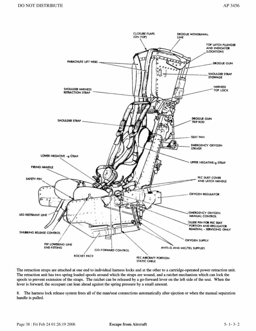
The retraction straps are attached at one end to individual harness locks and at the other to a cartridge-operated power retraction unit.The retraction unit has two spring loaded spools around which the straps are wound, and a ratchet mechanism which can lock thespools to prevent extension of the straps. The ratchet can be released by a go-forward lever on the left side of the seat. When thelever is forward, the occupant can lean ahead against the spring pressure by a small amount.
8. The harness lock release system frees all of the man/seat connections automatically after ejection or when the manual separationhandle is pulled.
DO NOT DISTRIBUTE AP 3456
Page 38 : Fri Feb 24 01:26:19 2006 Escape from Aircraft 5- 1- 3- 2
9. The leg restraint system prevents the legs from flailing during ejection. Cords are attached by shear pins to the aircraft floor andare routed through one-way snubber units in the seat pan and rings on the occupant’s leg garters to taper locks on the seat. Thesnubbers allow the lines to be tightened as the seat rises and the shear pins break when the legs are restrained. The snubbers maintaintheir grip until man/seat separation. Arm restraint is also provided on some seat/aircraft fits.
10. To operate the seat the firing handle is pulled sharply upwards a short distance to fire a cartridge. The pull force required isbetween 20 and 70 pounds. Gas from the cartridge operates the harness retraction unit, the canopy miniature detonating cord (MDC)initiator and the seat ejection gun.
11. The drogue gun, on the top left side of the seat, is fired by a trip rod which is attached to the aircraft. The drogue gun ejects apiston which removes a pin that secures closure flaps on top of the parachute container and then deploys the drogue. The drogue gunhas two separate cartridges, one mechanically fired by the trip rod 0.6 seconds after the trip operates during ejection, the other is gasfired by the barostatic time release unit (BTRU) or by operation of the manual separation handle. A shear pin is fitted through the topof the drogue gun barrel to retain the piston until the gun fires.
12. The BTRU on the top right of the seat provides for the automatic release of the drogue shackle, deployment of the personalparachute, and separation of the occupant from the seat after ejection. The automatic sequence commences with the firing of acartridge in the BTRU. A time delay mechanism and a main barostat are able to delay the firing of the cartridge, depending onejection conditions:
a. The mechanical time delay mechanism is triggered by the trip rod when the seat rises on ejection. If the delay mechanism isunobstructed it allows the BTRU cartridge to fire 1.5 seconds after ejection.
b. If the ejection takes place at altitude the main barostat prevents operation of the time delay until the man and seat havedescended to 10,000 ft where a tolerable oxygen and temperature environment exists. After ejection the drogue stabilized seatdescends rapidly with the occupant strapped in. At 10,000 ft the barostat removes its restraint on the time delay, which is thenfree to operate.
When the BTRU cartridge fires, the resultant gas operates a release mechanism to free the restraint on the parachute withdrawal linewithin the parachute container. At the same time a piston operates to release the drogue shackle and the top harness locks. Therelease of the drogue shackle frees the drogue from the seat, thereby initiating deployment of the personal parachute. The harnessbottom locks are released and the occupant can now be plucked from the seat as the parachute develops. Finally the second droguecartridge is fired, normally a redundant action but necessary in case the mechanical firing of the gun has failed.
13. A personal equipment connector (PEC), on the left hand side of the seat pan, provides a single action connection for theoccupant’s mic/tel, oxygen supplies, and g-suit when applicable. The seat portion is coupled to the oxygen regulator. A cover isprovided to fit whenever the man portion is not connected. The man portion of the PEC is part of the aircrew equipment assemblyand has an oxygen tube and mic/tel lead for connection to the occupant’s oxygen mask hose and helmet mic/tel respectively. Whenreleased, either manually or during seat separation, the leg restraint cords are also released.
14. The main oxygen system is connected to the seat via an automatic pull-off bayonet connector behind the seat pan and then bypipe to the regulator/PEC. An emergency oxygen cylinder at the rear of the seat feeds into the main supply line and has a releasemechanism which is tripped automatically by a striker during ejection, or can be operated manually at any time by operating a controlhandle on the seat pan.
Principle of Operation
15. Before the seat can be ejected it is first necessary to remove the canopy. The canopy may either be jettisoned or disintegrated byusing a miniature detonating cord (MDC). The MDC is a fine ribbon of explosive material with a dense backing material, such aslead, to direct the explosive force outwards through the canopy. The MDC shatters the canopy so that the seat can pass through itwithout resistance. The MDC is operated by the seat firing handle and there is therefore no delay in the ejection. When canopyjettison is required there is a time delay in the ejection sequence to allow the canopy to clear the ejection path of the seat.
16. When the seat gun is fired the acceleration imparted to the seat must be controlled to within limits which are physically safe forthe seat occupant. For this reason the acceleration is staged by using three cartridges which fire in sequence. The gun is fired whenthe seat handle is pulled. Gas pressure from the firing unit cartridge fires the primary cartridge. Gas from the primary cartridge then
DO NOT DISTRIBUTE AP 3456
Page 39 : Fri Feb 24 01:26:19 2006 Escape from Aircraft 5- 1- 3- 2

initiates the upward movement of the seat, extending the telescopic tubes. As the tubes rise ports are opened which allow the primarycartridge gas to ignite the two secondary cartridges in turn. When the tubes are fully extended, separation of the outer and inner tubesoccurs and the seat is then free of the aircraft.
17. The seat harness is retracted immediately the seat firing handle is pulled so that the occupant is held in the correct posture forejection. During the first few inches of seat travel the leg restraint system prevents damage to the legs, the seat main oxygen supply isdisconnected and the emergency oxygen supply is tripped on by a striker.
18. The remaining automatic functions are initiated as the static trip rods are pulled from the drogue gun and BTRU. From thismoment on seat separation and personal parachute deployment will occur automatically unless there is a failure of the drogue gun orBTRU.
19. In the event of a failure of the drogue gun or BTRU, or if premature separation is deemed necessary, the manual separationfacility may be used. The operation of the manual separation handle fires a cartridge which then operates the same mechanisms as theBTRU and also fires the drogue gun. The manual separation facility should be used with caution at high altitude because the rate ofdescent in the seat is greater than that of a parachute and exposure to the adverse temperature/oxygen environment will therefore beextended.
Rocket Assisted Ejection Seats
20. Many seats are fitted with rocket packs which fire after the cartridges to sustain the upward thrust of the ejection gun. The thrustangle of a rocket assisted seat can be adjusted to allow for changes in the seat centre of gravity due to variations in the boardingweights of users. The boarding weight of the user is set on a control on the side of the seat pan; the setting of the weightautomatically changes the thrust angle of the rocket pack.
Command Ejection
21. Command ejection systems allow seat ejection systems to interconnect so that the occupant of one seat can operate both seatssimultaneously. Such systems are usually arranged so that the aircraft captain can save time by initiating the ejection of a secondcrew member though in some cases it may be possible for the crew member to initiate the ejection of the captain in the case ofincapacitation.
22. Command ejection is controlled by an ON/OFF selector. When ‘ON’ is selected a cartridge in the selector valve fires when theseat firing handle is operated. Gas from the cartridge is passed to the harness retraction system of the second seat and, after a shortdelay fires a breech unit cartridge to initiate seat ejection.
23. A seat ejected by a command system will function in the same way as a seat ejected independently. However, on some types,should manual separation then be required, the occupant of the command ejected seat would need to pull the seat firing handle beforeoperating the manual separation lever.
Failure of Seat to Eject
24. If the seat fails to eject, the seat firing handle should be pulled sharply again. If, with the command ejection system operative,the commanded seat fails to eject, the seat occupant should immediately pull his own seat firing handle.
Seat and Canopy Safety
25. To prevent the inadvertent firing of the ejection seat or canopy jettison, or the operation of the MDC, safety pins are provided.The pins should be inserted when the aircraft is on the ground. Precise details of how and where to insert the safety pins varyaccording to the type of seat and cannot be given here. Personnel who have not been trained in the use of the safety pins should notbe permitted to enter a cockpit without supervision.
Seat Limitations
26. Seats with rocket assistance may be used at ground level with no forward speed provided the aircraft attitude is straight andlevel.
DO NOT DISTRIBUTE AP 3456
Page 40 : Fri Feb 24 01:26:19 2006 Escape from Aircraft 5- 1- 3- 2

27. Seats without rocket assistance may be used at ground level provided the speed is 70-90Kts, depending on the type of seat. Theaircraft attitude should be straight and level. If the aircraft is airborne and in a descent, the minimum height for ejection isapproximately ten percent of the rate of descent, ie at 1,500ft/min rate of descent the minimum safe height for ejection is about 150ftprovided the wings are level. More detail for a specific seat/aircraft combination is given in the appropriate Aircrew Manual.
Escape from Aircraft
Chapter 3 - Parachutes and Parachute Descent
Introduction
1. Although parachutes are used for a variety of purposes, their original function was for emergency escape in flight. This chapterdescribes that function. Aircrew must know how to operate and handle the type of parachute that they may have to use for anemergency abandonment.
2. The design of a parachute results from a careful study of the conditions under which it will be used including the height andspeed of operation, the weight it is required to support, the opening shock (usually about 9 g) and the rate of descent required. Themaximum rate of descent at impact, to avoid significant injury, is 8 m/s; that of the Irvin 24 is between 5.5 and 7.5 m/s and the ratefor the GQ aeroconical parachute is between 5 m/s and 6 m/s.
PARACHUTE CONSTRUCTION AND CARE
The Canopy
3. The Canopy is the drag-producing part of a parachute. It is made of nylon and is designed to form an umbrella-like shape duringdescent. Rigging lines provide the connection between the canopy and the user and they maintain the shape of the canopy duringdescent. Each rigging line is continuous from one lift web to the apex of the canopy and thence to the opposite lift web, by way ofdiametrically opposite points on the periphery of the canopy ie 12 rigging lines on a 24 gore canopy.
4. Parachute canopies are constructed of gores extending from the apex to the periphery. Each gore is made up of a number ofpanels; in each panel the material is cut on the bias ie the warp and weft of the material lie at an angle (45°) to the centreline of thegores. There are 4 panels per gore designated A to D from periphery to apex in the Irving 24 and 5 in the aeroconical parachute,designated A to E. The peripheral hem and the vent at the apex are reinforced.
5. There are two types of canopy - flat and shaped. A flat canopy can be laid out to form a circle; each gore being a straight-sidedsegment of that circle. The measurement of such a canopy is its flat diameter. A shaped canopy cannot be so laid out and themeasurement is its flying diameter. The flying diameter of a 7 m flat canopy is about 5.5 m.
6. Shaped canopies assume a deeper form when deployed than flat canopies because the gores have curved sides. The aeroconicalparachute has been developed from both basic types to have the following advantages:
a. A lower terminal vertical rate of descent than a flat canopy of the same flying diameter.
b. A lower opening shock than a similar flat canopy at the same IAS and altitude.
c. It is more stable and less inclined to oscillate.
7. An auxiliary parachute - a small canopy or vane parachute used to deploy the main canopy - is normally attached to the apex ofthe main canopy. This small canopy is stowed on, or contains, a spring so that when the closure pins of a pack are removed the springprovides the force necessary to throw the auxiliary parachute clear of the pack and into the slipstream. An auxiliary parachute is fittedto all ejection seat packs although the drogue system normally deploys the main parachute canopy - the auxiliary only functions whenthe main canopy is deployed following a manual separation.
DO NOT DISTRIBUTE AP 3456
Page 41 : Fri Feb 24 01:26:19 2006 Escape from Aircraft 5- 1- 3- 3

Parachute Packs
8. The emergency escape parachute, complete with rigging lines (and normally an auxiliary parachute) is stowed into various typesof fabric or solid pack. The type of pack depends on the type of seat used (static or ejection) and whether the pack is always worn inthe air.
9. All parachute packs fitted to ejection seats are operated automatically. The pack is opened by tension from a drogue. Someparachute packs associated with static seats are opened by a static line from the aircraft structure and connected to the pack openingmechanism. This opens the pack after a time delay which is also controlled by a barometric capsule to ensure that the pack cannotopen automatically at high altitude. In addition, all parachute packs can be operated manually. In these cases, the parachute isextracted by a pilot parachute. Those packs normally operated by a static line usually have a manual handle to activate the automaticsystem should the static line fail to work.
10. The parachute packs in Service use fall broadly into one of four types:
a. Head Box Packs. Head box packs have the advantage that the parachute cannot be damaged in storage and is less susceptibleto damage from contact with the seat structure during extraction. As the pack is fitted to the seat and not the man, manualbale-out is impossible, but there are other methods of deploying the parachute if the seat fails.
b. Back Type Packs. Back type packs can be classified into three distinct kinds. One is similar in shape to the seat type pack,but is positioned on the back near the shoulders, the aircraft seat back being suitably shaped to accommodate the pack in thisposition. The second kind of back pack is commonly called the ‘horse shoe pack’, because of the shape. This also fits into theaircraft seat back near the wearer’s shoulders. These two kinds are fitted to ejection seats. The third sort is worn by aircrew instatic seats in high flying aircraft and fits on the back between the shoulders and the hips. A similar pack is worn by airloadmasters and dispatchers whilst carrying out air dropping duties.
c. Seat Type Packs. Seat type packs are designed to fit into a shaped pan in the aircraft seat and the wearer sits on the pack.Such packs are normally used by crew members who remain in their seats during flight; this type of pack is used in many staticand some early ejection seats.
d. Chest Type Packs. Chest type packs are for use in aircraft where the use of permanently fitted assemblies is impracticable.They connect by snap hooks to the front of the parachute harness, and are connected only when an emergency appears imminent.Until this time, the pack is kept in a stowage provided in the aircraft.
11. All parachute packs, irrespective of type, contain a 7 m flat canopy (Irvin 24) except for the head box packs fitted to the MartinBaker Type 10 ejection seat (Hawk, Tornado) which contain a 5.2 m GQ aeroconical parachute.
12. Anti-squid lines are fitted to many parachute canopies. These lines consist of a pair of cords or tapes from the parachute risers tothe central vent of the parachute canopy. During the deployment of the parachute, the anti-squid lines transfer the tension from thedrogues directly to the crewman. This relieves the tension on the shroud lines and the periphery of the parachute allowing the canopyto open more quickly. As rapid parachute inflation is undesirable at higher speeds, the anti-squid lines are designed to break underthese conditions so that the parachute canopy inflates more slowly.
Parachute Harness
13. Several types of parachute harness are in use, differing from one another in design details, to provide for the particularrequirements of the seat, aircraft or wearer. In general they consist of a sling in which the wearer sits, and auxiliary straps to securethis sling to the wearer. The latter usually provide for adjustment in size. The straps meet at a quick release fitting normally fitted toa waist-belt situated in front of the body. Extensions of the sling above the shoulders, called the lift webs, connect to the parachuterigging lines. There are usually four of these lift webs, two on each side, described as left or right, front or rear, as appropriate. Onharnesses designed for use with chest type parachute packs there are only two lift webs, known as the left or right lift webs.
14. Most types of ejection seat use a combined harness, which combines the role of both safety harness and parachute harness. Latertypes of combined harness have only one set of adjusting buckles.
Parachute Care
DO NOT DISTRIBUTE AP 3456
Page 42 : Fri Feb 24 01:26:19 2006 Escape from Aircraft 5- 1- 3- 3

15. Survival Equipment Sections on all units take great care to ensure that parachutes are issued in perfect condition. However,aircrew must follow the advice given below to prevent damage during handling:
a. Never pick up or carry a parachute by:
(1) Any ring-shaped handle.
(2) Any knob.
(3) A flexible housing.
(4) Elastics or springs.
b. Never drop or throw a parachute.
c. Never place a parachute on an oil drum, battery, dirty bench, ground or damp area. Keep it away from stoves and radiators.
d. Do not hang a parachute by the harness or allow the harness to drag along the ground.
PARACHUTE OPERATION
Manual Operation
16. After an unassisted escape from the aircraft, the parachute is deployed by removing the closure pins from the parachute pack.This is done either by a static line or by pulling either a knob or a D-shaped ripcord handle, which is situated either on the left handside of the parachute harness or on the pack itself. This release is normally pulled from left to right across the body. The ripcordhandle of manually operated parachutes should be operated as soon as the parachutist is clear of all parts of the aircraft. When theclosure pins are removed, the auxiliary parachute springs out of the pack, and as this fills, it extracts and streams the main parachute,which has also been freed by the unfastening of the pack. The rigging lines are hanked inside the pack and are extended as the canopystreams.
Automatic Operation
17. The parachute packs associated with ejection seats and some packs used in static seats are operated automatically. Ejection seatautomation initiated by a Barostatic Time Release Unit (BTRU) is described in Chap 2. The automatically operated packs used instatic seats are fitted with a device known as the Barometric Power Unit (BPU) which is described below.
18. A BPU is needed to operate parachutes which may have to be used in high altitude escapes from aircraft where an ejector seat isnot fitted. Its purpose is to operate the opening mechanism of the assemblies after the wearer has fallen to a pre-set height, or after apre-determined delay. A powerful spring provides the motive force necessary to drive the time delay mechanism and withdraw theripcord pins; an aneroid capsule prevents the release from operating above a pre-set height. An escapement and pallet delaysoperation for a pre-determined time after falling to the barometric operating height. This height is normally 10,000 ft and the timedelay is 2 ± 0.5 s.
19. The release is normally housed within the parachute pack and is activated by the removal of a pin; the means by which this isdone varies with the type of installation, but is either by a static line to a point in the aircraft near the escape exit, or by the manualoperation of a D-ring or knob on the parachute harness. The time delay mechanism runs for its set time, but if the height of operationis more than the barometric height, an interference pin controlled by an aneroid device will prevent it from running until the pre-setaltitude is reached. At the end of the time delay, the spring is released and it withdraws the ripcord pins. If for any reason the wearershould suspect that the power unit has failed, or if he has failed to fasten his static line to the aircraft, he can pull the manualparachute which will exert a direct pull on the pack rip pins and the auxiliary parachute will be ejected and extract the main parachutecanopy.
PARACHUTE DESCENT AND LANDING
Action to Control Descent
DO NOT DISTRIBUTE AP 3456
Page 43 : Fri Feb 24 01:26:19 2006 Escape from Aircraft 5- 1- 3- 3

20. Following a manual escape it is possible that the body may somersault before the parachute is deployed, whether this is achievedmanually or automatically. If height permits, body stability can be achieved by adopting the “free fall” position, ie body arched back,legs straight and slightly parted (about 450 mm), arms held straight out at right-angles to the body.
21. It is not possible in this Manual to quote one drill that can apply to all aircraft escapes and all circumstances. Following aground level ejection there will be little time to do much more than concentrate on the landing. However, whenever practicable, theVital Actions listed below must be carried out in the descent as soon as the main canopy is fully deployed:
a. Inflate the life preserver.
b. Unclamp the oxygen mask.
c. Check the security of the PSP lowering line.
d. Lower the PSP unless the descent is likely to be into trees or overhead cables.
22. If time permits, the following subsequent actions may be taken to minimize problems in the descent and landing:
a. Disconnect and discard the oxygen mask.
b. Pull up the PSP if oscillations become excessive.
c. Adopt the appropriate landing position.
d. Release the parachute when the landing is complete, or as described in para 32 if in water.
23. Descent by parachute can be influenced by the manipulation of the lift webs. Correct application of this parachute flyingtechnique will:
a. Reduce oscillation.
b. Reduce drift and thereby the horizontal component of the landing impact.
c. Enable the parachutist to attempt to avoid obstacles and, to a limited degree, select his landing area.
24. Oscillation. One of the characteristics of the flat canopy emergency parachute is its tendency to oscillate, often violently.During a long descent this can be most unpleasant, resulting sometimes in sickness or panic. Oscillation may be reduced to someextent by pulling down on any lift web or pair of front or rear lift webs. The oscillation of the man may be aggravated by loweringthe PSP, as it can swing one way whilst the parachutist is swinging the other; thus subjecting him to a series of violent jerkingmovements. Note: This oscillation is significant with the flat canopy (Irvin 24) only. It does not occur so much with the GQaeroconical parachute.
25. Control of Drift. Pulling on a lift web tends to make the parachutist drift in the direction of the pull, but as air is being spilledout of the canopy, it also causes an increase in the rate of descent. From this it will be seen that pulling on the downwind side willincrease the drift across the ground and the force of landing. Pulling on the upwind side will reduce drift and landing speed. Whenbelow 1,000 ft it is therefore advantageous to check drift as follows:
a. Look at any suitable fixed point on the ground and assess the direction of drift. As the wind velocity may changesignificantly below 1,000 ft the drift should then be continually monitored. At heights in excess of 1,000 ft there is littleawareness of descent but below this height the rate of descent and drift become progressively more noticeable, especially in thelast few hundred feet.
b. If drifting forwards, check drift by reaching as high as possible and grasping the back lift webs, with the thumb inwards andthe palm to the front. Pull down until the hands are level with the face.
c. If drifting backwards, pull down on the front lift webs as described above.
DO NOT DISTRIBUTE AP 3456
Page 44 : Fri Feb 24 01:26:19 2006 Escape from Aircraft 5- 1- 3- 3
d. If drifting sideways, pull down on the front lift webs and just before reaching the ground let up on the lift web on the side towhich you are drifting.
e. As long as the drift continues in the original direction it is not advisable to let up before landing, except in the case ofsideways drift when the lift web on the downwind side is let up. Should the pull on the lift webs overcome the drift then the liftwebs must be let up gently just before reaching the ground.
NOTE:
1. Maintain the correct parachute position throughout the descent, body relaxed, hands on lift webs when notcarrying out vital actions.
2. All manipulation of the lift webs should be positive and steady. They must not be jerked down or let up tooquickly due to the risk of re-introducing oscillation.
3. In the event of the parachute turning, or an alteration of drift, change to the correct lift webs; if close to theground, let up gently.
4. Aeroconical parachutes have a significant glide ratio. This feature, known as drive, may be up to 6 m/s andhence it will have a marked effect on the apparent drift.
5. Chest packs (and some others) have harnesses with only 2 lift webs; one lift web only should be pulled downto reduce oscillation and drift.
6. During the descent the escapee should note the main features of the surrounding countryside.
26. Avoidance of Obstacles. If there is a danger of landing on buildings, trees or other obstructions, it is possible to change thedescent path by side-slipping. This is accomplished by pulling down on the lift webs or rigging lines on the side towards which it isdesired to move. This causes air to spill from the opposite side of the canopy producing a movement in the desired direction. Thecanopy may appear to collapse in a violent side slip, but this need not cause alarm as it will recover as soon as the lift webs arereleased. Side slipping causes a marked increase in the rate of descent and should not be done close to the ground except in extremeemergency. When side slipping is used to avoid landing on rough ground the object should be to land short or steer round to one sideof the obstacle. Attempts to glide over an obstacle will invariably fail because of the increased rate of descent.
Parachute Landing
27. When making a forward landing, the lower limbs and feet should be turned across the line of drift to allow the roll aftertouchdown to be made on the side of the leg and thigh, feet and legs should be together, knees slightly bent, head tucked well in andthe arms, with hands grasping the lift webs, should be bent, with the elbows held forward. The initial landing shock is reduced by theflat of the feet, through comparatively well-braced legs, although the shock is reduced by the relaxed attitude of the body. Thereshould be no attempt to strike or beat the ground with the feet; the body should touch with the feet, leg, thigh and buttock. Ontouchdown, the near shoulder should be twisted round and the fall completed diagonally across the back.
28. When making a sideways landing, the sequence of movements is almost identical with that of a forward landing, except thatsince the body is already across the line of drift, further turning is unnecessary; the final twisting of the shoulders at touchdown neednot be so pronounced.
29. When making a backward landing, the parachute position should be held until approaching the ground when the lower limbsshould be turned across the line of drift so that the landing is half backward, half sideways. On touchdown the body should touchwith feet, leg, thigh and buttocks, and the fall completed in a roll across the back as before.
30. After landing the parachute canopy should be deflated immediately by pulling in on a handful of rigging lines at ground level.This will avoid being dragged. If, in a strong wind dragging takes place before the canopy is deflated, roll onto the back and undo thequick release fitting (QRF).
31. If the descent is made into trees it will not be as dangerous as may be imagined. The drill is:
a. Retain the helmet and do not lower the PSP.
DO NOT DISTRIBUTE AP 3456
Page 45 : Fri Feb 24 01:26:19 2006 Escape from Aircraft 5- 1- 3- 3

b. Adopt the normal parachute landing position but with the arms across the front of the face until the descent ceases. (Theparachutist may crash through light branches and land on the ground.)
c. If the parachute catches in a tree, try to get a safe anchorage on a branch or the trunk, but with the minimum of movement.Do not release the QRF until a safe anchorage has been obtained. The PSP may be dropped and the PSP lanyard used to secureequipment to the tree and assist in the descent.
32. If the descent is made into water, carry out the following action (See also Vol 6, Pt,2, Sect 2, Chap 1):
a. Check that the lobes of the life preserver are not trapped in the harness and that it is inflated.
b. Raise the visor and discard the oxygen mask.
c. Lower the PSP as late as possible to minimize oscillation and adopt the parachute position.
d. In the water, adopt the stable position - big X, PSP between the legs. If the parachute canopy falls on top of you, do notpanic. There is no danger of drowning as long as the life preserver is inflated. If there is any wind the canopy should drift clear.Should the canopy collapse on top of you this would mean a light wind and a low sea state. Hence there would be little dangerand no reason to panic. Float with the head back and, using alternate arms, grasp a handful of material and draw it over the headand down to the chest, grasping another handful before releasing. Where possible, work along an embedded line between twogores; if the apex is reached first continue across it to the periphery. Breathing is no more difficult than normal while under thecanopy if the parachute material is held clear of the face.
e. Locate the QRF and rotate it clockwise through 90°. With thumbs behind and fingers in front, press the QRF, release harnessand push it clear.
f. Pull in the PSP and pull the handle.
g. Inflate and board the liferaft as quickly as possible.
33. After a descent into water in high winds the survivor may be dragged in the harness. Should this happen, he must roll onto hisback in the dragging position, which is:
a. Chin on chest, shoulders and back rounded.
b. Legs maintained wide apart.
c. Hands on release mechanism.
This position affords a comfortable and stable ride with the face well clear of the water. The protective helmet reduces watersplashing on the face. The parachute should be released by squeezing the QRF; if the dragging force is high the straps may bind inthe groin. Maintain the legs wide apart and work on the leg straps with the hands.
34. With systems deployed by a drogue bullet and duplex drogues the duration of drag is very short as the bullet falls into the waterand sinks. This submerges the drogues which then acts as a sea anchor and the line rapidly collapses the main chute. In additionmost modern ejection seats are fitted with parachutes that have water deflation pockets. These pockets rapidly fill with water anddeflate the parachute.
Summary
35. The construction, care and operation of parachutes has been dealt with in general terms in this chapter. Further details ofindividual parachute assemblies may be found in AP 1182A. Information on the uses of parachutes in survival situations is containedin Vol 6, Pt 2, Sect 2. The parachuting technique is the result of the lessons learned from numerous descents by aircrew andexperienced parachutists; the advice given should enable aircrew to avoid serious injury after abandoning an aircraft in flight.
DO NOT DISTRIBUTE AP 3456
Page 46 : Fri Feb 24 01:26:19 2006 Escape from Aircraft 5- 1- 3- 3

FLYING
Basic Flying
Chapter 1 - General Flying
Introduction
1. Because of the diversity of aircraft types in service, it is impracticable to discuss every aspect of all exercises that a pilot is likelyto attempt; the following paragraphs, therefore, contain the general considerations applicable to most types of aircraft whenperforming the basic flying manoeuvres. It should be appreciated that many factors affect these considerations and allowance shouldbe made for those not mentioned in this Section.
2. A pilot must be thoroughly familiar with his aircraft, and his knowledge of the location and function of all controls, instrumentsand equipment should be such that he feels at home in the cockpit. He must also know all the flying limitations and emergencysystems. To this end, full use should be made of all available training aids such as flight simulators, instructional fuselages, andmock-ups of fuel, hydraulic and electrical services. The chief sources of information are Aircrew Manuals, the Aircraft ServicingManual - Ground Handling, and AP3456 Vol 2.
Preparation for Flight
3. Flight Planning. It is the captain’s duty to ensure that, before flight, appropriate members of his crew have carried out the correctflight planning, and that all the information necessary to ensure the safe navigation of the aircraft has been obtained. The success ofany sortie may depend on the thoroughness of this pre-flight preparation.
4. Meteorological Briefing. No flight should be undertaken without obtaining information about the weather in the area, along theroute to be flown, and at the destination and alternate airfields.
5. Passengers. The aircraft captain must be acquainted with the relevant orders governing the flying of passengers, ie JSP 318,Queen’s Regulations, and the appropriate Air and Command Staff Instructions. The captain is responsible for the safety of hispassengers and for ensuring that they are adequately equipped with appropriate safety and survival equipment for the proposed flight.He must ensure that they are fully briefed on the following, aspects:
a. Authority of the Aircraft Captain. See JSP 318.
b. Safety and Survival Equipment. The fitting, adjustment and operation of the appropriate safety and survival equipment mustbe fully explained and, where necessary, demonstrated.
c. Crash, Ditching and Abandonment Procedures. The crash or ditching positions and exits must be pointed out, and theexecutive orders relating to these emergencies and to abandonment must be stated.
d. Oxygen Equipment. Where applicable, the passengers must be suitably instructed in the operation and fitting of oxygenequipment.
e. Restrictions. Where applicable, the no smoking/naked lights restrictions must be pointed out. Passengers must be madeaware of any restrictions on their movement within the aircraft.
6. Personal and Safety Equipment. The serviceability of all equipment taken into the air must be carefully checked. The captainmust ensure that he and the crew have the appropriate safety, survival, oxygen and R/T equipment.
7. Order Books and Authorization. JSP 318 (Military Flying Regulations), Command and Group Air Staff Instructions and theStation Flying Order Book should all be read before first flying from an airfield. Thereafter these books should be read periodicallyand Section A of the Flying Order Book should be checked before each flight so that any new orders can be read at once. All flights
DO NOT DISTRIBUTE AP 3456
Page 47 : Fri Feb 24 01:26:19 2006 Basic Flying 5- 2- 1- 1
should be correctly authorized in accordance with JSP 318.
8. Checks Before Starting. Before starting, the following general checks should be made:
a. The aircraft should, if practicable, be facing into wind. This precaution will ensure the best possible cooling in the case ofpiston engines and, in the case of jet engines, will prevent the hot exhaust gases re-entering the engine.
b. The aircraft should be standing on firm ground which should be free of loose objects that could be drawn into the engine ordamage the airframe.
c. The aircraft should be positioned so that the jet efflux or slip-stream will not damage any equipment, aircraft, vehicle,building or people.
d. The aircraft’s wheels should be securely chocked.
e. A fire extinguisher of adequate capacity must be available to deal with any fires that may occur whilst starting up.
f. The area around the aircraft should be clear of obstructions: this is particularly important in the case of the larger swept-wingaircraft where the wing tips are not visible from the cockpit.
g. The aircraft should be free from deposits of frost, ice and snow. When necessary a de-icing fluid should be used but, becauseunder certain conditions the wetted surface can actually enhance the accumulation of wet snow, there should be no significantdelay between de-icing and take-off. Particular attention should be paid to the leading edges, control surfaces, flaps, slats andassociated mechanisms, hinges and gaps. Deposits on control surfaces could put them out of balance and cause flutter; those onhinges may re-freeze in flight and jam controls. All inlets and vents should also be cleared. Procedures for the use of de-icingfluid are in AP 107C-0200-1.
After Start-up
9. On some types of engine, icing of probes can cause over-reading of power gauges. To prevent this possibility and of damage to,or flame out of, the engine it may be advisable to select engine anti-icing if icing conditions are present or possible. As a guideengine icing can be assumed possible if the outside air temperature (OAT) is less than 10 deg Celsius and there is precipitation,standing water, or the runway visual range (RVR) is less than 1,000 metres. Use propeller de-icing if appropriate.
Taxiing
10. Any special points to be watched while taxiing are described in the Aircrew Manual for the type. The brakes should be testedtogether as soon as possible after starting to taxi while the speed is still low. Whilst taxiing, the brake pressure should be checkedfrequently and if it falls significantly the aircraft should be stopped before the brakes lose their effectiveness. In general, the amountof power used in taxiing should be kept as low as possible since aircraft brakes can quickly overheat if abused, or if a long period oftaxiing is necessary involving much stopping and starting. Particularly when leaving dispersal, the effects of the jet efflux orslipstream on loose ground equipment must be considered and the aircraft halted if damage is likely.
11. If the aircraft has nose wheel steering, the use of wheel brakes will be confined to slowing and stopping the aircraft. However,when using toe brakes in conjunction with nose wheel steering, care must be taken not to damage the nose wheel steering mechanismby braking against the direction of turn, ie if the aircraft is being turned to starboard by using the steering, do not apply the left toebrake to slow the aircraft. In any event, the aircraft must not be turned on a locked wheel. On aircraft fitted with a tandem bogieunder-carriage, very high loads can be induced if sharp turns are made. The severity of the loads does not vary much with aircraftweight but increases rapidly with tightness of turn, and fatigue fractures have occurred which can be attributed directly to repeatedapplication of sharp turning loads.
12. Taxiing speeds depend entirely on the circumstances, but the overall consideration must be to limit the speed to that which givestime to cope with any emergency and to limit the stresses on the undercarriage. When taxiing among, or close to obstructions, orwhen turning sharply, the speed must be kept low.
13. In tail wheel aircraft, where the centre of gravity is behind the main wheels, there is a tendency for a turn, once started, to tightenup. In nose wheel aircraft, where the centre of gravity is ahead of the main wheels, a natural directional stability results and the
DO NOT DISTRIBUTE AP 3456
Page 48 : Fri Feb 24 01:26:19 2006 Basic Flying 5- 2- 1- 1

turning force has to be maintained to sustain the turn.
14. The wind velocity can be an important consideration when taxiing. The effect of the wind on the keel surfaces normally tends toturn an aircraft into wind and this is most noticeable in light aircraft with large keel surfaces. In a strong wind, the effectiveness ofthe brakes in countering weather-cocking may well be the limiting factor in the use of these aircraft. In strong or gusty winds thecontrols must be held firmly to prevent them being blown against their stops; Aircrew Manuals indicate when control locks may beused when taxiing. In aircraft fitted with irreversible power-operated controls, the wind has no effect on the controls.
15. In large aircraft it is normal to post crew members in suitable positions in the aircraft to act as additional look-outs. If theforward view is restricted by the nose, as in some single piston engine aircraft, taxi slowly and yaw the nose from side to side toensure that the way ahead is clear. If doubt exists about the clearances or position of obstacles, the aircraft should be stopped.
16. During taxiing, in icing conditions, the use of reverse thrust should be kept to a minimum. Excessive reverse thrust can result inice contamination of the wing leading edges. For the same reason aircraft should not be taxied too close behind another taxiingaircraft.
Take-off
17. Before take-off ensure that the wings are not contaminated by ice or snow and that fuel, airframe and, engine anti-icing controlsare set as appropriate. Refer to the relevant Aircrew Manual and ODM when operating from contaminated runways. Considerre-cycling the undercarriage after take-off to clear snow, slush or water which may freeze the undercarriage in the “UP” position.
Climbing
18. An aircraft will climb if, when trimmed in straight and level flight at a set IAS, the power is increased. The rate of climb varieswith the amount of surplus power and the air speed, the maximum rate of climb being achieved at full power and at a recommendedclimbing speed which varies with height and weight. Aircrew Manuals give the engine settings and air speeds, or Mach numbers, tobe used on the climb. (See Vol 1, Pt 1 Sect 1, Chap 2 for aerodynamic principles of the climb).
19. Having ensured that the area into which the aircraft is to be climbed is clear, the following technique should be used for enteringthe climb: climbing power should be applied and as the speed approaches climbing speed the attitude should be adjusted to that forthe climb; the airspeed should be allowed to stabilize and the aircraft should be trimmed, small adjustments can be made to correctand hold the speed, retrimming as necessary. During the climb the attitude will have to be readjusted to maintain the climbing speed;power settings, engine temperatures, oxygen flow and pressurization should be checked periodically. If the forward view is poor inthe climbing attitude, the aircraft should be turned occasionally to check the sky ahead unless operational considerations require aclimb on a constant heading.
In Flight
20. The build up of ice in flight may be very rapid and pilots should avoid icing conditions for which their aircraft are not cleared.Even relatively small amounts of ice can have a significant and dangerous effect on an aircraft’s performance and control.Instructions given in the relevant Aircrew Manual concerning the use of anti-icing and de-icing equipment should be followed.
21. Jet Engine Handling. Engine limitations must be watched, remembering the different temperature limitations may apply invarying conditions. The amount of power adjustment required to climb is usually small, but attention must be paid to the jet pipetemperature(s) or (TGT), particularly at high altitudes where this becomes more critical. If the temperature exceeds the maximum itshould be reduced by decreasing the rpm; increasing the air speed is not recommended as it may well have the opposite effect.During the climb, small throttle adjustments may be required to maintain constant rpm, depending on the engine characteristics.
22. Turbo Prop Handling. Advice of engine handling techniques for particular aircraft types will be found in the aircrew manual.For taxiing reduced rpm can be selected by operating a switch but older types and multi-engined aircraft may require manual rpmcontrol. Multi-engined types may also need adjustment to propeller pitch to assist in manoeuvring on the ground. Engines not havingthe advantage of computerized control may need throttling to maintain engine temperature and torque limits in the climb and tosynchronize engines in the cruise. Some engines, in cold conditions, may become torque limited before being temperature limited inthe climb.
23. Piston Engine Handling. During a sustained climb the rpm should be maintained as near possible to the Aircrew Manual
DO NOT DISTRIBUTE AP 3456
Page 49 : Fri Feb 24 01:26:19 2006 Basic Flying 5- 2- 1- 1

recommended figures. In a constant throttle setting engine power output will fall as height is gained and the throttle must be used tomaintain the required manifold pressure. The engine will tend to overheat during the climb because of a combination of high powerand low IAS; temperature should therefore be carefully monitored to maintain the temperature within recommended limits and ifnecessary rate of climb should be sacrificed by reducing power or increasing speed.
Effectiveness of Controls
24. Air Speed. At a given height the effectiveness of a control surface varies with the speed of the air passing over it. Withpropeller-driven aircraft the effectiveness of the rudder and elevator increases appreciably when these lie within the propellerslipstream. In general, however, if the speed of the airflow over a control surface is reduced, a larger control movement is requiredfor a given change and rate of change of aircraft attitude.
25. Altitude. As height is increased the controls become less effective. This is because at a constant IAS, the TAS, and thus thedirectional inertia, increases as altitude increases.
Straight and Level Flight
26. A high standard of straight and level flight is the basis of all accurate flying and is essential to good navigation; it involves flyingthe aircraft on a constant heading, at a constant height and air speed in balanced flight (see Vol 1, Pt 1, Sect 1, Chap 11). Enginehandling will depend on the requirements of the flight (eg maximum range) and should accord with the recommendations in theAircrew Manual. As in all flying exercises, a good look-out is essential and this should be systematically combined with frequentscanning of the instruments.
27. Stability and Trimming. Aircraft are generally stable and so tend to return to straight and level flight if they have been disturbedfrom it. Full use should be made of all trimming devices to relieve the pilot of any loads on the controls and thus reduce fatigue. Athigher altitudes, stability is normally reduced and accurate trimming then becomes increasingly more difficult but correspondinglymore important.
28. Flaps. When flying straight and level at low speed some advantage may be gained by lowering the flaps to the positionrecommended in the Aircrew Manual; the stalling speed is thereby reduced, more power is required to overcome the additional dragof the flaps at a given speed and, with propeller-driven aircraft, the additional slipstream increases the effectiveness of rudder andelevator controls. In addition, the use of flap will improve the forward view by reducing the high nose attitude associated with flyingat low speeds.
Turning
29. The force which turns an aircraft is the horizontal component of the lift obtained by banking. The total amount of lift requiredfor any turn is therefore greater than that for the same speed in level flight but the drag will also be higher since the extra lift can onlybe obtained by increasing the angle of attack. This increase in drag, shown at a given power setting by a reduction in speed, is morequickly apparent in slow aircraft though it also applies to faster aircraft at the higher angles of attack.
30. Loading. As the angle of bank is increased in a turn, the total lift must be gradually increased if the aircraft is to maintain heightand obtain the greater horizontal component needed to make the aircraft turn on a decreasing radius. A progressive increase in lift andloading, obtained by gradually increasing the angles of bank and attack, can be continued until one of the following limits isreached:
a. The aircraft stalls when the angle of attack reaches the critical angle.
b. The pilot reaches his g threshold.
c. The g limit of the aircraft is reached.
The angle of attack must not be increased sharply or suddenly since the applied load can become large enough to overstress theaircraft, although the pilot may not black out because of the short duration of the load and/or because he is wearing an anti-g suit.The loading imposed on the aircraft will be evident to the pilot from the physiological effects of the increasing g and the indicationsof the accelerometer.
DO NOT DISTRIBUTE AP 3456
Page 50 : Fri Feb 24 01:26:20 2006 Basic Flying 5- 2- 1- 1

31. Stalling Speed. The stall in a turn always occurs at a higher speed than in level flight and this is known as the g stall. During aturn, the more the power used, the larger the angles of bank and attack applied, the greater will be the horizontal component of theinclined lift vector and the smaller the turning radius; at the same time the g will increase. If, while tightening the turn, the aircraftapproaches the g stall (usually indicated by buffeting), recovery is made simply by reducing the backward pressure on the controlcolumn and, if not already at full power, increasing the power. If the aircraft stalls, the recovery action is to release the backwardpressure on the control column and recover from the stall before levelling the wings. This is described more fully in Chap 3 of thissection.
32. Maximum Rate and Minimum Radius Level Turns. Maximum rate or minimum radius turns are flown at full power and atmaximum lift, ie on the fringe of the g stall; theoretically the higher the IAS that can be maintained under these conditions, the fasterthe rate and the smaller the radius of turn. If less than full power is used the rate of turn is less and the radius is larger. Stalling speedis proportional to g and therefore increases as the angle of bank increases and the turn tightens. In practice, when gradually tighteninga turn at a constant IAS, the initial response from the aircraft is a slight increase in rate of turn and a considerable decrease in radius;as the g stall limit is approached the rate of turn starts increasing rapidly but the rate of decrease of the radius falls off and eventuallyincreases. This is because compressibility and other effects begin to affect the wing at a fairly low Mach number thus reducing therate at which the radius would otherwise diminish until a point is reached at which they completely cancel any benefit to be gained byincreasing the speed. These facts should be borne in mind when flying at high speed or in poor visibility.
33. Turning at Low Speed. Low speed implies a high angle of attack giving a relatively small margin above the stalling angle. Anyturn commenced at low speed is limited in radius and rate of turn since the margin of speed between the level flight stalling speed andthe g stall is small; power should therefore be used to prevent the speed from falling any lower. At the lowest speeds just above thestall, only fractional amounts of g are required to reach the stall.
34. Compressibility in Turns. Any increase in angle of attack and g accelerates the flow of air over the upper surface of the wing.At a high TAS therefore, the increased angle of attack during a turn induces the onset of compressibility effects sooner, ie at a lowerspeed and Mach number than when no loading is applied.
35. Effect of Altitude on Turning. Because of the reducing air density with altitude and the adverse effect of compressibility on thelift obtained at a given IAS and angle of attack, the g to which the aircraft can be subjected without stalling is lower. Maximum ratesof turn are much reduced and turning circles increased, and fighter-type aircraft, which could easily be damaged through excessive gat low altitudes, are not able to exceed 1.5 to 2 g at their highest working altitudes.
Descending
36. A descent can be made at different rates and air speeds, with or without the use of engine, flaps or airbrakes. Aircrew Manualsindicate how maximum rate, cruising or gliding descents are best made.
37. Slow Descents. It is a relatively simple matter to obtain a slow rate of descent, whether following a particular method describedin the Aircrew Manual or by simply reducing the power. When descending slowly from considerable heights a large distance isalways covered and the flight plan should allow for this.
38. Maximum Rate Descents. Operational necessity or an emergency may require the maximum possible rate of descent through alarge height band from a high altitude. Airbrakes should be opened, power adjusted and speed allowed to build up to therecommended Mach number or IAS. The Mach number used may depend on the degree of control available and compressibilityeffects whilst at lower altitudes the IAS is usually the limiting factor. The amount of power used varies with the type of aircraft andthe requirements of the operation or emergency. Frequently, in rapid descents from high altitude, the large and comparatively rapidchange of air temperature and the high humidity at lower levels will cause frosting or misting of the cockpit windows and even of thefaces of the instruments and, if this occurs, full use should be made of the defrosting and demisting devices fitted. It may also benecessary to allow time for the aircraft to warm up at low altitude to disperse this misting before attempting to land. Allowance mustbe made for the height needed to level out from rapid descents so that the manoeuvre is completed at a safe height above ground level;at a high IAS and angle of descent, this allowance can be of the order of several thousand feet.
39. Airmanship. Although the view during the descent is usually good it may be necessary to turn frequently to check that thedescent is being made into a clear space. Descents of any sort through cloud should not be made unless either the pilot is sure thatwithin the circle of uncertainty of position there is adequate clearance between the ground and cloud base, or some form of controlleddescent is being used.
NOTE:
DO NOT DISTRIBUTE AP 3456
Page 51 : Fri Feb 24 01:26:20 2006 Basic Flying 5- 2- 1- 1
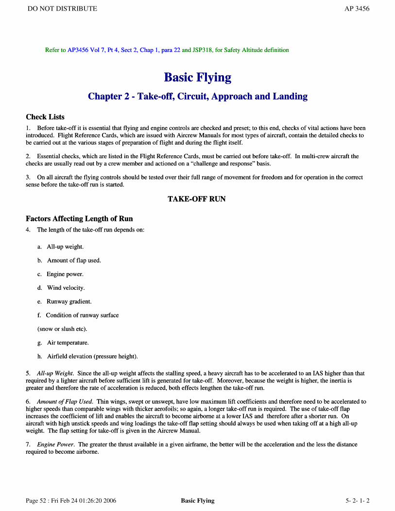
Refer to AP3456 Vol 7, Pt 4, Sect 2, Chap 1, para 22 and JSP318, for Safety Altitude definition
Basic Flying
Chapter 2 - Take-off, Circuit, Approach and Landing
Check Lists
1. Before take-off it is essential that flying and engine controls are checked and preset; to this end, checks of vital actions have beenintroduced. Flight Reference Cards, which are issued with Aircrew Manuals for most types of aircraft, contain the detailed checks tobe carried out at the various stages of preparation of flight and during the flight itself.
2. Essential checks, which are listed in the Flight Reference Cards, must be carried out before take-off. In multi-crew aircraft thechecks are usually read out by a crew member and actioned on a “challenge and response” basis.
3. On all aircraft the flying controls should be tested over their full range of movement for freedom and for operation in the correctsense before the take-off run is started.
TAKE-OFF RUN
Factors Affecting Length of Run
4. The length of the take-off run depends on:
a. All-up weight.
b. Amount of flap used.
c. Engine power.
d. Wind velocity.
e. Runway gradient.
f. Condition of runway surface
(snow or slush etc).
g. Air temperature.
h. Airfield elevation (pressure height).
5. All-up Weight. Since the all-up weight affects the stalling speed, a heavy aircraft has to be accelerated to an IAS higher than thatrequired by a lighter aircraft before sufficient lift is generated for take-off. Moreover, because the weight is higher, the inertia isgreater and therefore the rate of acceleration is reduced, both effects lengthen the take-off run.
6. Amount of Flap Used. Thin wings, swept or unswept, have low maximum lift coefficients and therefore need to be accelerated tohigher speeds than comparable wings with thicker aerofoils; so again, a longer take-off run is required. The use of take-off flapincreases the coefficient of lift and enables the aircraft to become airborne at a lower IAS and therefore after a shorter run. Onaircraft with high unstick speeds and wing loadings the take-off flap setting should always be used when taking off at a high all-upweight. The flap setting for take-off is given in the Aircrew Manual.
7. Engine Power. The greater the thrust available in a given airframe, the better will be the acceleration and the less the distancerequired to become airborne.
DO NOT DISTRIBUTE AP 3456
Page 52 : Fri Feb 24 01:26:20 2006 Basic Flying 5- 2- 1- 2

8. Wind Velocity. Taking off into wind requires a shorter run because an aircraft at rest, pointing into wind, already has an IASequivalent to the wind speed. The additional advantages of taking off into wind are:
a. The ground speed at the time of unsticking is lower.
b. At the lower ground speed the stresses on the undercarriage and tyres are reduced.
c. There is no tendency to drift.
d. Directional control is improved in the initial stages of take-off.
e. The angle of climb after take-off is steeper because, although the rate of climb is unaffected, the ground speed is lower (seeFig 1).
f. The ground speed is lower following possible engine failure or an abandoned take-off, so that the touchdown is made moreslowly and the stopping distance is shorter.
9. Runway Gradient. If the take-off is uphill, then the aircraft will be slower to accelerate and consequently have a longer take-offrun. Similarly, a downhill slope will give a shorter take-off run. An uphill slope of one degree will increase the take-off distance byapproximately 10%.
10. Condition of Runway Surface. The retarding effect of snow or slush on the take-off run can be severe, and comparatively smalldepths of slush are sufficient to prevent an aircraft from accelerating to its unstick speed. Before attempting to take-off with slush or
snow on the runway, the situation should be assessed very carefully. If the depth of slush exceeds 1 cm (1
2 in), or dry snow 6 cm (21
2
in), then take-off should not be attempted. The increased take-off distances will vary with aircraft type but depths of less than 1 cm ofslush can give up to a 50% increase in take-off distance.
11. Air Temperature. An increase in air temperature will decrease its density; this raises the TAS required to unstick and solengthens the take-off run. Low air density also reduces the maximum power of jet and unsupercharged piston engines, an effectwhich adds to the distance covered. The thrust of jet engines at a given rpm is reduced by 4% - 5% for each 5 °C rise in ambienttemperature (above standard temperature 15 °C).
12. Airfield Pressure Altitude. The reduced density at altitude increases the take-off run for the reasons explained in para 11. Thethrust of jet engines is reduced by 2% - 3% for each 1,000 ft increase in airfield pressure altitude.
13. Operating Data Manual (ODM). An ODM is issued for most aircraft types, which allows the factors mentioned in paras 5 - 12to be taken into account in arriving at precise calculations on take-off performance (see also AP 3456 Vol 1, Pt 3, Sect 4, Chap 6).
5-2-1-2 Fig 1 Effect of Wind on Take-Off Run and Initial Angle of Climb
DO NOT DISTRIBUTE AP 3456
Page 53 : Fri Feb 24 01:26:20 2006 Basic Flying 5- 2- 1- 2

TAKE-OFF TECHNIQUE
General
14. Take-off techniques vary with different classes of aircraft. The main classes of aircraft from this point of view are:
a. Single turbojet engine aircraft with nose wheel undercarriage.
b. Single propeller driven aircraft with nosewheel undercarriage.
c. Single propeller driven aircraft with tail wheel undercarriage.
d. Multi-engine aircraft with nose wheel undercarriage.
Single Turbojet Engine Aircraft with Nose Wheel Undercarriage
15. The aircraft should be taxied forward on the runway for a few yards to straighten the nose wheel and then the throttle openedsmoothly to full power. In the initial stages of the run direction should be controlled with the nose wheel steering or wheel brakes butas soon as the rudder becomes effective this should be used. A slightly shorter take-off run is obtained by first opening up to themaximum power that can be held on the brakes, then releasing the brakes and applying the remainder of the power. When take-offpower is reached, the engine instruments should be checked. At the recommended IAS the nose wheel should be raised clear of therunway, thus setting a moderate nose-up attitude which should be maintained until the unstick speed is reached. As the speed risesabove the nose wheel lift-off speed, the elevator/tailplane effectiveness increases and there is a tendency for the attitude to becomemore nose-up. This must be countered by a suitable control movement because, if the nose-up attitude becomes exaggerated, the dragrises to an extent which reduces the rate of acceleration and, in extreme cases, may prevent any further acceleration. As therecommended unstick speed is approached, smooth backward pressure on the control column should enable the aircraft to unstick atthe required speed. On many aircraft the period between nose wheel lift-off and unstick speed is short and the technique justdescribed is considerably modified. With these aircraft, on reaching rotate speed, steady backward pressure is applied to the controlcolumn; the aircraft then rotates and unsticks in one smooth, continuous manoeuvre. This method may not be practicable for allaircraft because of the high rotational speeds achieved by the nose wheel assembly when taking off from a rough surface. Whensafely airborne the brakes should be applied and the undercarriage retracted whilst a shallow climb is maintained and the IAS allowedto increase to the initial climbing speed. On some aircraft this is done automatically. Flaps, if used, should also be raised at a safeheight and air speed. If climbing power is less than full throttle, power should be reduced in accordance with the recommendations in
DO NOT DISTRIBUTE AP 3456
Page 54 : Fri Feb 24 01:26:20 2006 Basic Flying 5- 2- 1- 2

the Aircrew Manual.
Single Propeller Driven Aircraft with Nose Wheel Undercarriage
16. Since single engined propeller aircraft with nose wheel undercarriages are almost in the flying attitude, the asymmetric blade orgyroscopic effects during the take-off run (see Vol 1, Pt 1, Sect 4, Chap 1) will not be felt until the nose wheel is lifted off the ground,and even then they will be negligible. Most nose wheels are steerable and can be used to maintain directional control during the earlypart of the take-off run.
Single Propeller Driven Aircraft with Tail Wheel Undercarriage
17. The aircraft should be taxied forward for a few yards to straighten the tail wheel. With the control column held aft of the centralposition, the throttle should be smoothly opened to take-off power. Any tendency to swing should be corrected with the rudder, thecorrections becoming smaller as the rudder becomes more effective with increasing air speed. As the speed increases, the aircraftshould be brought into the flying attitude by a progressive forward movement of the control column, taking care not to get the nosetoo low. As flying speed is approached, a smooth, backward pressure should be applied to the control column to unstick at the correctspeed. When safely airborne, a shallow climb should be maintained allowing the IAS to build up to the recommended climbingspeed. At a safe height the flaps, if used, should be raised. When the flaps are fully retracted, power should be reduced to theclimbing setting.
Multi-Engine Aircraft with Nose Wheel Undercarriage
18. The take-off technique for these aircraft is the same as that for single engine types except that the possibility of engine failureduring and immediately after take-off must be considered. These considerations are detailed in Sect 2, Chap 8.
19. When the ODM is available for use with any aircraft type, the particular maximum stop speed for the take-off conditions andrunway length should be ascertained.
Use of Reheat
20. When reheat is used for take-off, no special technique is necessary other than to check the reheat operations and raise theundercarriage and flap as soon as possible after becoming airborne; this is necessary (because of the rapid acceleration) to preventexceeding the limiting IAS for these items.
Taking Off in a Cross-wind
21. Because of the advantages listed in para 8, it is usual to take-off as nearly as possible into wind. However, when a long take-offrun is needed it may be preferable to use the longest runway regardless of the wind direction, unless the wind is very strong. Across-wind take-off requires a longer run due to the lower headwind component.
22. Drift. For a given wind speed the drift is inversely proportional to IAS, ie the lower the IAS, the greater the drift. Consequentlythe amount of drift correction when unsticking is less at higher speeds. Nose wheel aircraft, being inherently stable on the ground,have less tendency to weathercock when taking off across wind.
23. Technique for Cross-Wind Take-off. An aircraft tends to weathercock into wind and this tendency must be anticipated. In theinitial stages the controls should be handled as for a normal take-off, paying extra attention to directional control. In multi-engineaircraft directional control may be assisted by differential use of power, but it must be appreciated that this lengthens the take-off runas more time is needed to reach full power. When the unstick speed is reached the aircraft should be lifted cleanly off the ground andmust be prevented from dropping back onto the runway. A clean unstick is especially important when taking off from a roughsurface, or in gusty conditions, when an unexpected bump or gust may force the aircraft into the air before full flying speed has beenreached. In these circumstances it is advisable to hold the aircraft down deliberately until a speed slightly above the normal take-offspeed is reached. In all aircraft, particularly those with sweepback, a cross-wind may cause the into-wind wing to rise during theperiod from just before to immediately after becoming airborne. This is caused by a “yawed” airflow over the wings which increasesthe lift on the into-wind wing and is aggravated by the partial blanking of the other wing by the fuselage. This is a transitory effectwhich disappears shortly after becoming airborne when the cross-wind overcomes the inertia of the aircraft and causes it to drift. Itshould be anticipated and corrected as soon as it starts. After becoming airborne, and at a safe height, the aircraft should be turnedinto wind to counteract drift and allowed to track along the line of the runway.
DO NOT DISTRIBUTE AP 3456
Page 55 : Fri Feb 24 01:26:20 2006 Basic Flying 5- 2- 1- 2
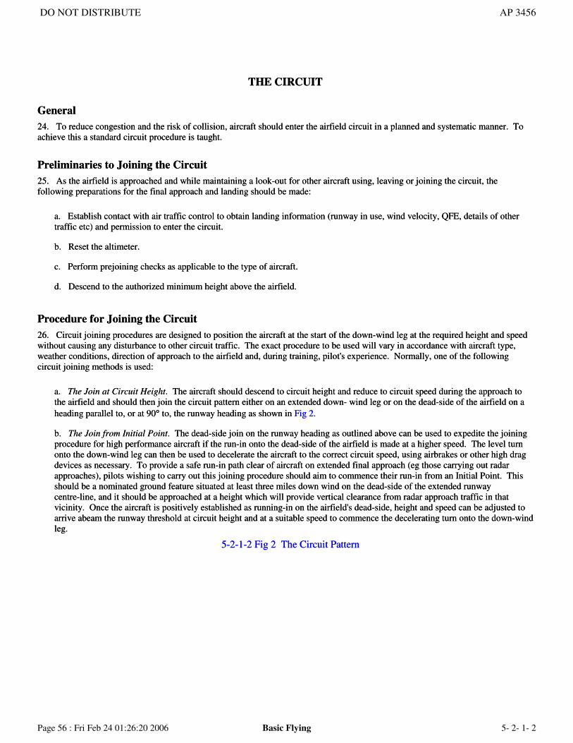
THE CIRCUIT
General
24. To reduce congestion and the risk of collision, aircraft should enter the airfield circuit in a planned and systematic manner. Toachieve this a standard circuit procedure is taught.
Preliminaries to Joining the Circuit
25. As the airfield is approached and while maintaining a look-out for other aircraft using, leaving or joining the circuit, thefollowing preparations for the final approach and landing should be made:
a. Establish contact with air traffic control to obtain landing information (runway in use, wind velocity, QFE, details of othertraffic etc) and permission to enter the circuit.
b. Reset the altimeter.
c. Perform prejoining checks as applicable to the type of aircraft.
d. Descend to the authorized minimum height above the airfield.
Procedure for Joining the Circuit
26. Circuit joining procedures are designed to position the aircraft at the start of the down-wind leg at the required height and speedwithout causing any disturbance to other circuit traffic. The exact procedure to be used will vary in accordance with aircraft type,weather conditions, direction of approach to the airfield and, during training, pilot's experience. Normally, one of the followingcircuit joining methods is used:
a. The Join at Circuit Height. The aircraft should descend to circuit height and reduce to circuit speed during the approach tothe airfield and should then join the circuit pattern either on an extended down- wind leg or on the dead-side of the airfield on aheading parallel to, or at 90° to, the runway heading as shown in Fig 2.
b. The Join from Initial Point. The dead-side join on the runway heading as outlined above can be used to expedite the joiningprocedure for high performance aircraft if the run-in onto the dead-side of the airfield is made at a higher speed. The level turnonto the down-wind leg can then be used to decelerate the aircraft to the correct circuit speed, using airbrakes or other high dragdevices as necessary. To provide a safe run-in path clear of aircraft on extended final approach (eg those carrying out radarapproaches), pilots wishing to carry out this joining procedure should aim to commence their run-in from an Initial Point. Thisshould be a nominated ground feature situated at least three miles down wind on the dead-side of the extended runwaycentre-line, and it should be approached at a height which will provide vertical clearance from radar approach traffic in thatvicinity. Once the aircraft is positively established as running-in on the airfield's dead-side, height and speed can be adjusted toarrive abeam the runway threshold at circuit height and at a suitable speed to commence the decelerating turn onto the down-windleg.
5-2-1-2 Fig 2 The Circuit Pattern
DO NOT DISTRIBUTE AP 3456
Page 56 : Fri Feb 24 01:26:20 2006 Basic Flying 5- 2- 1- 2
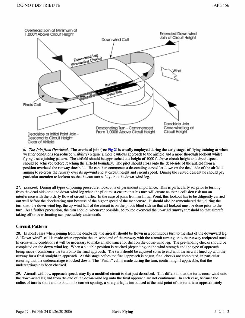
c. The Join from Overhead. The overhead join (see Fig 2) is usually employed during the early stages of flying training or whenweather conditions (eg reduced visibility) require a more cautious approach to the airfield and a more thorough lookout whilstflying a safe joining pattern. The airfield should be approached at a height of 1000 ft above circuit height and circuit speedshould be achieved before reaching the airfield boundary. The pilot should cross onto the dead-side of the airfield from aposition overhead the runway threshold. He can then commence a descending curved let-down on the dead-side of the airfield,aiming to re-cross the runway over its up-wind end at circuit height and circuit speed. During the curved descent he should payparticular attention to lookout so that he can turn safely onto the down-wind leg.
27. Lookout. During all types of joining procedure, lookout is of paramount importance. This is particularly so, prior to turningfrom the dead-side onto the down-wind leg when the pilot must ensure that his turn will create neither a collision risk nor aninterference with the orderly flow of circuit traffic. In the case of joins from an Initial Point, this lookout has to be diligently carriedout well before the decelerating turn because of the higher speed of the manoeuvre. It should also be remembered that, during theturn onto the down-wind leg, the up-wind half of the circuit is on the pilot's blind side so that all lookout must be done prior to theturn. As a further precaution, the turn should, whenever possible, be routed overhead the up-wind runway threshold so that aircrafttaking off or overshooting can pass safely underneath.
Circuit Pattern
28. In most cases when joining from the dead-side, the aircraft should be flown in a continuous turn to the start of the downward leg.A “Down-wind” call is made when opposite the up-wind end of the runway with the aircraft turning onto the runway reciprocal track.In cross-wind conditions it will be necessary to make an allowance for drift on the down-wind leg. The pre-landing checks should becompleted on the down-wind leg. When a suitable position is reached (depending on the wind strength and the type of approachbeing made), commence the turn onto the final approach. The turn should be adjusted so as to end with the aircraft lined up with therunway for a final straight-in approach. At this stage before the final approach is begun, final checks are completed, in particularensuring that the undercarriage is locked down. The “Finals” call is made during the turn, confirming, if applicable, that theundercarriage has been checked.
29. Aircraft with low approach speeds may fly a modified circuit to that just described. This differs in that the turns cross-wind ontothe down-wind leg and from the end of the down-wind leg onto the final approach are not continuous. In each case, because theradius of turn is short and to obtain the correct spacing, a straight leg is introduced at the mid-point of the turn, ie at approximately
DO NOT DISTRIBUTE AP 3456
Page 57 : Fri Feb 24 01:26:20 2006 Basic Flying 5- 2- 1- 2

90° to the down-wind leg. These legs are known as the cross-wind and base legs respectively.
THE APPROACH
General
30. The first requirement for a good landing is a good approach, which may be made with or without assistance from the engine. Anengine-assisted approach is usual, but the pilot must be capable of making a glide approach in many single engine training types ofaircraft so that he is competent to perform a forced landing if the engine fails.
Use of Flap
31. The use of flap during an approach will give:
a. A steeper path of descent at a given speed and power setting.
b. A lower stalling speed, thus permitting an approach at a lower airspeed without reducing the safety margin and, hence, ashorter landing run.
c. A better view over the nose.
The amount of flap used will depend on the type of aircraft and the wind conditions prevailing.
Effect of Wind
32. The two main advantages of making an approach and landing into wind are that the groundspeed is reduced to a minimum for agiven airspeed and drift is eliminated. Consequently the landing run will be shortened, the undercarriage will not be subjected tounnecessary side loads and the tendency to swing will be reduced. Also, if it is necessary to go round again, the aircraft will be in thebest position to regain height rapidly.
Wind Gradient
33. A progressive decrease in wind speed in the lower layers near the ground, ie wind gradient, will be most pronounced when astrong wind is blowing near an uneven surface. The effect of a sharp wind gradient on an aircraft approaching to land is to cause asudden reduction in IAS. With heavier aircraft this reduction may cause a rapid sink and a heavy landing or an undershoot. Theeffect of the gradient is sometimes aggravated by turbulence which may greatly increase the rate of sink. Therefore, if a strong windgradient is suspected, the approach should be made at a higher speed than normal and extra power used as required to prevent theaircraft sinking rapidly as it nears the ground.
Gusts
34. Gusts are strongest when the wind is strong, and on hot days, when the effect of thermal currents caused by the uneven heatingof the earth's surface is most pronounced. In conditions of moderate to high wind they may also be caused by the horizontal shieldingeffect of buildings and trees. The effect of gusts may either be similar to that of a wind gradient or may alternate with a suddenincrease in airspeed and lift.
Manoeuvrability
35. At the low speeds used on the approach the amount of bank and g that can be applied is limited. The higher the landing weight,the higher the stalling speed and the less the amount of bank that can be safely used at a given airspeed. Whereas, for example, 45° ofbank could be safely applied at the speed used when turning onto the final approach, the same amount of bank used at a lowerairspeed at some later stage of the approach could induce a stall and considerably increase the rate of descent. This considerationapplies particularly to aircraft having combinations of high wing loading and sweepback and when operating at or near the maximumlanding weight.
DO NOT DISTRIBUTE AP 3456
Page 58 : Fri Feb 24 01:26:20 2006 Basic Flying 5- 2- 1- 2

Engine Handling
36. With many aircraft, Aircrew Manuals stipulate the minimum power that should be used on the approach until definitelycommitted to the landing. If the aircraft undershoots with the power below that recommended, the engine acceleration characteristics- particularly with gas turbines - may entail a considerable and possible disastrous delay before sufficient power is reached to correctthe approach path. In addition, with the power below the required figure, any attempt to hasten its build-up may cause a compressorstall. Unless necessary, therefore, steep approaches needing little or no power should be avoided.
Approach Path
37. The classic form of approach is that during which height, speed and power are progressively reduced until the aircraft arrives atthe touchdown point with the engine throttled back and the speed at its lowest value above the stall. An alternative method, morecommonly used, is to set a constant speed immediately upon starting the final approach, thereafter controlling the rate of descent bythrottle movements. This speed is known as approach speed and is calculated by adding a certain value to the target threshold speed.The threshold speed is governed by the landing weight of the aircraft.
38. The precision approach path indicator (PAPI) provides pilots with an indication of the correct glide slope information during avisual approach to landing. A PAPI installation, which can be used from ranges in excess of 12 Km (7.5nm), consists of a bank offour light units on each side of the runway. The beam of light from each unit comprises a white upper half and a red lower half,separated by a very narrow transition band. The changeover from one colour to the other is so precise that at a range of 3 Km (2nm)an observer has only to move about 1 metre up or down to see the changeover. The four units are set up at different angles so thatthere is one degree difference between the highest and lowest settings; the highest setting is the one nearest to the runway, the fivedifferent indications which a pilot will receive from the PAPI installation in respect of the aircraft's relationship to the glidepath areshown in Fig 3. An unimpeded view of all eight units is of vital importance. Each unit contains three lamps, three red filter glassesand three lenses, which are aligned to produce a high intensity beam of light. If the aircraft is on the correct glide slope, the pilot seestwo red and two white lights; if he goes high he progressively sees more white lights and if he goes low he sees more red lights.
39. The PAPI glide slope angle should be identical to the station's precision approach glidepath. If there is no precision approachradar, it will be determined by local operational and flight safety requirements, but should normally be 21
2 or 3 degrees. The PAPI
units can be adjusted through a range from 2 to 10 degrees. The units should be positioned:
5-2-1-2 Fig 3 PAPI Indications
a. To be coincident with ILS touchdown.
b. To be coincident with PAR touchdown where no ILS is fitted.
DO NOT DISTRIBUTE AP 3456
Page 59 : Fri Feb 24 01:26:20 2006 Basic Flying 5- 2- 1- 2

c. Approximately 850 ± 260ft (260 m ± 80 m) from the threshold where neither ILS nor PAR is fitted.
d. To ensure that the minimum wheel clearance over the threshold is not less than 6 m (20 ft). There is a variation in the eye towheel heights from one aircraft type to another so PAPIs are aligned so that they are correct for the aircraft type which is themajor user at each airfield. The eye threshold for each airfield fitted with PAPIs is published in the En-route Supplement(Threshold Crossing Height). Aircrew need to know the eye to wheel height for their aircraft type, in the landing configuration,so that when landing at an airfield at which their aircraft is not the major user, they can apply it to the figure quoted in theEn-route supplement, and check that the PAPIs give them an adequate safety margin.
40. Irrespective of the type of approach, the aim should always be to maintain a constant and moderate rate of descent. Althoughsome circumstances may demand steep approaches with a high rate of descent and little or no power, or flat approaches with a lowrate of descent and a high power setting, such approaches should not be used under normal conditions since the margins of safety arereduced.
41. On aircraft having high wing loadings the rate of descent must be kept moderate. If the rate of descent is high, a comparativelylarge amount of height and power is needed to check the descent progressively and any attempt to hasten the correction can easilycause a g stall.
LANDING
Definitions
42. The following terms are used during the approach to land:
a. Final Approach. This is considered to start at the completion of the final turn in a visual circuit, or when lined up with therunway in the case of an instrument approach.
b. Round-out. This is the term used to describe that part of the final approach during which the rate of descent achieved on theapproach is reduced to the lower rate required for the landing.
c. Hold-off or Float. This describes the subsequent period in which the aircraft is flown parallel to the ground with increasingangle of attack and falling air speed until the aircraft touches down.
Nose Wheel Aircraft
43. As the aircraft approaches the threshold of the runway the rate of descent should be checked by a gentle backward pressure onthe control column; at the same time the throttle should be closed gradually. In this attitude the airspeed decreases and the aircraftshould be lowered gently onto its main wheels. If after rounding out there is a tendency to float or gain height, the nose has beenraised too high during the round-out; the nose should be lowered slightly and the main wheels deliberately run onto the ground, soavoiding any tendency to float. The rate at which power is reduced is not the same for all aircraft; some types, particularly highlyloaded aircraft and those with swept wings, require some power during the round-out to prevent an excessively rapid drop in speeddue to the high drag in the nose-up attitude. Unless power is used to prevent this, the rate of descent can increase causing anundershoot or a heavy landing (see para 41).
44. An aircraft with a nose wheel undercarriage should be landed on the main wheels with the nose wheel held off the ground. Thisattitude is little different from the attitude of the aircraft while on a normal approach and therefore only a small change of attitude isrequired when rounding out. Since the centre of gravity is ahead of the main wheels the aircraft tends to pitch forward onto its nosewheel on touchdown and this reduces the angle of attack so that there is no tendency to balloon off the ground. The nose wheelshould be lowered onto the ground before the brakes are used although on some aircraft the nose wheel cannot be held off the groundonce the main wheels have touched down. Brakes should then be used to decelerate and maintain a straight landing run.
45. On some aircraft the nose wheel may be held off initially and aerodynamic braking employed. This consists of holding theaircraft in a marked tail-down attitude for the first part of the landing run, so offering the largest possible area to the airflow, givingmore drag and slowing the aircraft while reducing the amount of brake required subsequently. If aerodynamic braking is used, thelanding run is longer than if the nose wheel had been placed on the runway and the wheel brakes applied at the earliest possiblemoment. Prolonged aerodynamic braking is useful only when there is sufficient runway available or if the brakes have failed.
DO NOT DISTRIBUTE AP 3456
Page 60 : Fri Feb 24 01:26:20 2006 Basic Flying 5- 2- 1- 2

Tail Wheel Aircraft
46. Basic Technique. The rate of descent is checked by rounding out and reducing power. In the tail wheel aircraft however, thecontrol column should be moved progressively back increasing the attitude (angle of attack) as the speed decreases, and holding theaircraft off the ground. Too rapid a movement of the control column causes the aircraft to balloon away from the ground, while tooslow a movement allows the aircraft to sink onto its main wheels and bounce. In a well-judged landing the moment is reached whenthe aircraft will sink onto all three wheels together. This is known as the three-point landing and has the following advantages:
a. The touchdown speed is the lowest possible (little more than the stalling speed) and this, combined with maximumaerodynamic braking due to the high angle of attack, gives the shortest landing run.
b. The brakes may be used early in the landing run.
c. There is less danger of the aircraft nosing over if the brakes are used too fiercely or the wheels enter soft ground.
47. Wheel Landing. A wheel landing is one in which the main wheels are placed on the ground before the tail wheel. This type oflanding differs from the three-point landing in that once the aircraft is flying just above the ground, it is not held off but the mainwheels are placed gently but deliberately on the ground. The wheel landing may, on occasions, be preferred to the three-point landingbecause:
a. The change of attitude when landing is less and there is no hold off, so judgement is easier.
b. It has certain advantages when landing in a cross-wind.
c. It provides a safer means of landing laden aircraft.
The main disadvantage of the wheel landing is that the speed is higher at the moment of touchdown, making for a longer landing run.
Types of Approach and Landing
48. Engine-assisted Approach. The use of power on the approach enables the IAS and the rate of descent to be adjusted safely overa wide range. However, very low, flat approaches using high power are undesirable. Other characteristics of the engine-assistedapproach are:
a. By using the required power settings it is possible to regulate the angle of approach despite varying wind strengths.
b. The change of attitude when rounding out is small compared with that for a glide approach.
c. The use of power reduces the stalling speed and thus a lower approach speed can be used.
In propeller-driven types only, the increased slip-stream gives more rudder and elevator control than when no power is used.
49. Glide Approach. The salient features of the glide approach are:
a. As there is no power with which to adjust the rate of descent, a high standard of accuracy is required to judge the position onthe base leg at which to close the throttle.
b. The correct gliding speed is maintained by use of the elevator and the nose of the aircraft must be lowered in turns tomaintain that speed.
c. The rate of descent is high and the angle of descent may be steep, particularly in advanced trainers and operational aircraft. Ifdescending into a strong wind the rate of sink may appear alarmingly high.
d. A considerable change of attitude is made during the round-out; therefore, to avoid g stalling, the round-out must be startedearlier and at a higher IAS than for an engine-assisted approach.
DO NOT DISTRIBUTE AP 3456
Page 61 : Fri Feb 24 01:26:20 2006 Basic Flying 5- 2- 1- 2

50. Flapless Landing. Aircrew Manuals advise on the speeds and techniques used for a flapless landing. Flapless landings shouldbe practised occasionally to ensure that the pilot is able to use this method should the flap mechanism fail. On high performanceaircraft the low drag with the flaps up often causes some difficulty in losing speed after turning onto the final approach. To cross therunway threshold at the recommended speed, adjustments should be made in good time to avoid arriving at the runway at too high aspeed. A flapless approach and landing differs in the following ways from one in which flaps are used:
a. The approach and touchdown speeds are higher.
b. Because of a, the radius of the final turn may be larger.
c. The descent path is flatter and consequently the approach may be longer.
d. The change of attitude in the round-out is smaller.
e. The period of float during the hold-off, in a tail wheel aircraft, is longer.
f. The landing run is longer.
Cross-wind Approach and Landing
51. There are two recognized methods of making the final approach (see Fig 4): one maintaining wings level and the other allowinga degree of bank.
a. Wings Level Technique. Drift is counteracted by heading the aircraft into wind, keeping the wings level, so that the aircrafttracks along the intended landing path (see Fig 4a).
b. Banking into Wind. Drift is counteracted by banking sufficiently into wind and using rudder to align the aircraft with theintended landing path. This involves a slight sideslip (see Fig 4b). Aircraft which have restrictive undercarriage sideloadlimitations may only be cleared to use this technique.
52. Nose Wheel Aircraft. In the final stages of the approach there is normally less drift because the wind speed decreases near theground. This should be anticipated but the temptation, in Fig 4a, to align the aircraft with the intended landing path or runway toosoon, or in Fig 4b, to take off bank prematurely, must be resisted. In either case, the round-out, which is otherwise normal, iscompleted with the drift correction still applied. For the wings level method, once the round-out has been completed, the ruddershould be applied smoothly and firmly to yaw the aircraft into line with the landing path and then placed positively on the ground. Inswept-wing aircraft particularly, there is a tendency for the into-wind wing to rise as the aircraft is yawed straight; this must beanticipated and corrected with aileron. Similarly, for the banking technique, at round-out the aircraft should be rolled wings level,maintaining balance, and placed immediately on the runway.
53. Tail Wheel Aircraft - Wheel Landing. In a strong cross-wind a three point landing is not advisable. Instead, the aircraft shouldbe yawed into line with the landing path as soon as the hold-off height has been reached and, without further delay, both main wheelsplaced firmly on the ground, direction being maintained with rudder while this is still effective. Although involving a longer landingrun, a possible misjudgement of the moment of stall is avoided.
Overshoot Procedure
54. To overshoot, the throttle should be opened smoothly to the power required, the wings levelled and the undercarriage raisedwhilst the IAS is allowed to increase to the recommended figure. Flaps should be set according to the Aircrew Manual procedure.Once a decision to overshoot has been made, particularly at night or in instrument flight conditions, no further height should be lostand the aircraft should be held in a steady climb while overshoot actions are completed.
5-2-1-2 Fig 4 Cross-Wind Approach and Landing
DO NOT DISTRIBUTE AP 3456
Page 62 : Fri Feb 24 01:26:20 2006 Basic Flying 5- 2- 1- 2
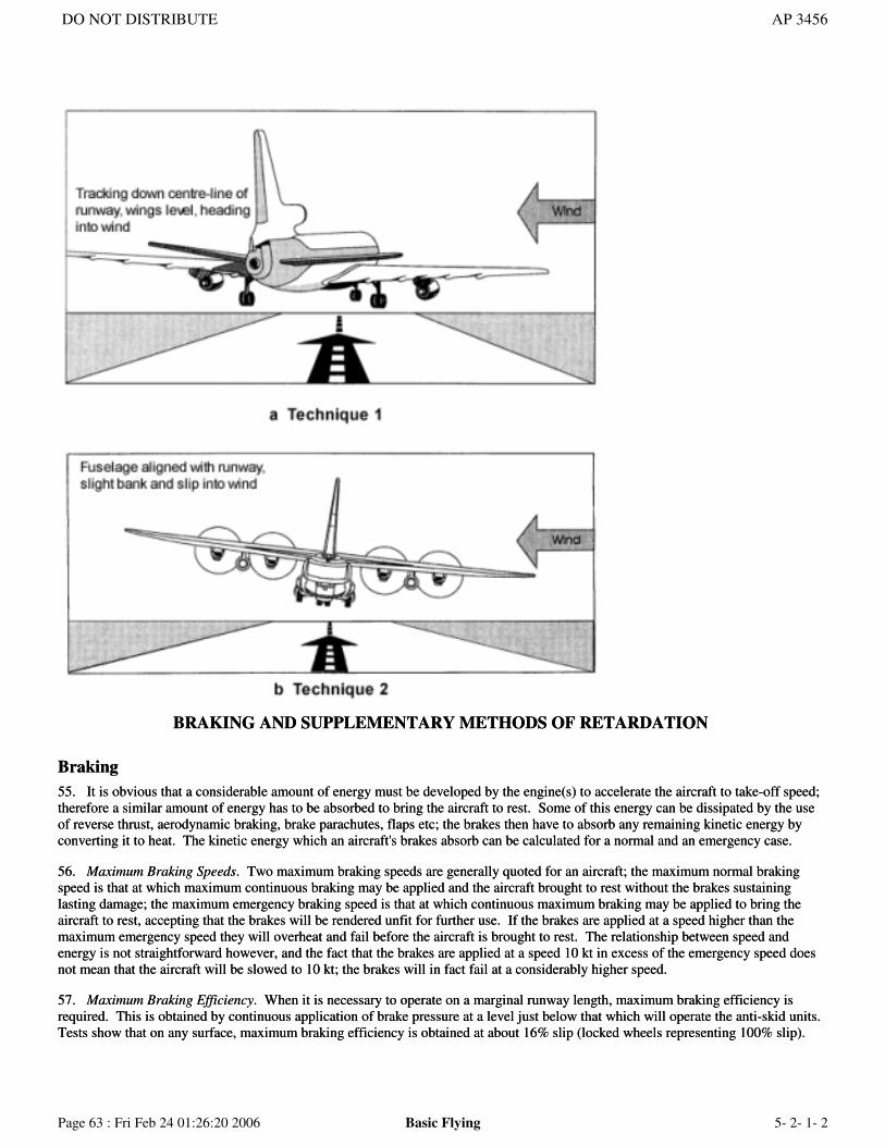
BRAKING AND SUPPLEMENTARY METHODS OF RETARDATION
Braking
55. It is obvious that a considerable amount of energy must be developed by the engine(s) to accelerate the aircraft to take-off speed;therefore a similar amount of energy has to be absorbed to bring the aircraft to rest. Some of this energy can be dissipated by the useof reverse thrust, aerodynamic braking, brake parachutes, flaps etc; the brakes then have to absorb any remaining kinetic energy byconverting it to heat. The kinetic energy which an aircraft's brakes absorb can be calculated for a normal and an emergency case.
56. Maximum Braking Speeds. Two maximum braking speeds are generally quoted for an aircraft; the maximum normal brakingspeed is that at which maximum continuous braking may be applied and the aircraft brought to rest without the brakes sustaininglasting damage; the maximum emergency braking speed is that at which continuous maximum braking may be applied to bring theaircraft to rest, accepting that the brakes will be rendered unfit for further use. If the brakes are applied at a speed higher than themaximum emergency speed they will overheat and fail before the aircraft is brought to rest. The relationship between speed andenergy is not straightforward however, and the fact that the brakes are applied at a speed 10 kt in excess of the emergency speed doesnot mean that the aircraft will be slowed to 10 kt; the brakes will in fact fail at a considerably higher speed.
57. Maximum Braking Efficiency. When it is necessary to operate on a marginal runway length, maximum braking efficiency isrequired. This is obtained by continuous application of brake pressure at a level just below that which will operate the anti-skid units.Tests show that on any surface, maximum braking efficiency is obtained at about 16% slip (locked wheels representing 100% slip).
DO NOT DISTRIBUTE AP 3456
Page 63 : Fri Feb 24 01:26:20 2006 Basic Flying 5- 2- 1- 2
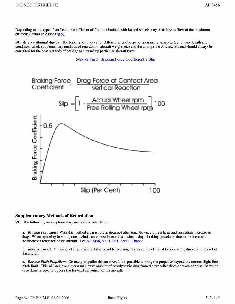
Depending on the type of surface, the coefficient of friction obtained with locked wheels may be as low as 50% of the maximumefficiency obtainable (see Fig 5).
58. Aircrew Manual Advice. The braking techniques for different aircraft depend upon many variables (eg runway length andcondition, wind, supplementary methods of retardation, aircraft weight, etc) and the appropriate Aircrew Manual should always beconsulted for the best methods of braking and retarding particular aircraft tyres.
5-2-1-2 Fig 5 Braking Force Coefficient v Slip
Supplementary Methods of Retardation
59. The following are supplementary methods of retardation:
a. Braking Parachute. With this method a parachute is streamed after touchdown, giving a large and immediate increase indrag. When operating in strong cross-winds, care must be exercised when using a braking parachute, due to the increasedweathercock tendency of the aircraft. See AP 3456, Vol 1, Pt 1, Sect 1, Chap 9.
b. Reverse Thrust. On some jet engine aircraft it is possible to change the direction of thrust to oppose the direction of travel ofthe aircraft.
c. Reverse Pitch Propellers. On many propeller-driven aircraft it is possible to bring the propeller beyond the normal flight finepitch limit. This will achieve either a maximum amount of aerodynamic drag from the propeller discs or reverse thrust - in whichcase thrust is used to oppose the forward movement of the aircraft.
DO NOT DISTRIBUTE AP 3456
Page 64 : Fri Feb 24 01:26:20 2006 Basic Flying 5- 2- 1- 2

60. In general when using supplementary retardation, the threshold must be crossed at the correct speed, the throttle closed (toobviate float) and touchdown made at the desired point. Once firmly on the runway the nose wheel should be lowered before usingbrake parachute or reverse thrust. Recommended maximum wheel braking should be applied with the weight firmly on the mainwheels. After a fully braked landing it is essential that sufficient time should elapse before a further take-off is attempted so that theheat capacity of the brakes is restored, by cooling, to cater for a possible subsequent abandonment of take-off.
Braking on a Wet Surface
61. When landing on wet surfaces retardation may be considerably reduced, depending on the degree of wetness and type of runwaysurface. The touch-down techniques for a short landing should be adopted. Maximum braking efficiency is obtained by making afirm touchdown and applying light, continuous braking as soon as the aircraft is firmly on the runway and the wheels have had time tospin-up. The full length of the runway should be used.
Emergency Retardation
62. Rapid retardation may be achieved by certain aircraft types designed and approved for the purpose by engaging an arresterbarrier or cable arrester gear. Full details of techniques and engagement limitations are in the relevant Aircrew Manuals and a briefdescription of airfield arresting systems is to be found in the Annex to this chapter. Aircraft limitations vary widely but the followingfactors are generally applicable and need to be taken into account before contemplating an arrester engagement.
63. Arrester Barriers. A net barrier may be available at some airfields at the upwind end of the runway to arrest aircraft in anemergency which would otherwise overrun (see Annex to this chapter). Considerations are:
a. Propeller aircraft are not permitted to engage net barriers.
b. Some types will not be permitted to engage if the net has a steel top cable which might penetrate the canopy.
c. Pilots should aim for the centre of the net, leaving power and brakes off so that the net becomes slack when the aircraft isbrought to rest.
d. Aircrew Manuals will specify barrier entry speed limitations which will depend upon all up weight and whether the barrier istorsioned for light or heavy engagement.
e. External stores and full fuel tanks should normally be jettisoned before engagement, preferably whilst airborne.
f. The canopy must remain closed during engagement until the aircraft has come to a rest.
64. Cable Arresting Gear. Arrester cables are installed at both ends of certain runways. Only aircraft approved in the AircrewManual and with a serviceable hook fitted may engage cables. Both the approach end cable or the overrun cable may be engaged asthe situation demands. Considerations are:
a. Limitations on trampling rigged cables and on hook lowering are given in the Aircrew Manual as are maximum engagementspeeds for the all up weight.
b. Cables are of differing diameters and may not be suitable for some hooks.
c. The cable should be engaged at right angles near the centre. It is normally recommended to avoid the exact centre if therunway has centreline lighting, which may cause hook bounce and result in a missed engagement.
d. Brakes should be off on engagement and remain off when arrested. Brake assistance may or may not be recommended duringthe deceleration phase.
e. Power should be set to idle (no reverse thrust) on engagement. Use of power subsequently to limit excessive cable pull backmay be recommended.
f. Nosewheel steering, if fitted, may be used for directional control during any pull back after engagement.
DO NOT DISTRIBUTE AP 3456
Page 65 : Fri Feb 24 01:26:20 2006 Basic Flying 5- 2- 1- 2

5-2-1-2 Fig 6 Development of Tyre Aquaplaning
AQUAPLANING
Definition
65. As an unbraked pneumatic tyre rolls along a water-covered runway, it contacts and displaces the stationary water. The resultingchange in momentum of the water creates hydrodynamic pressure which reacts on the runway and tyre surfaces. This hydrodynamicpressure tends to increase as the square of the groundspeed. As the groundspeed increases the inertia of the water tends to retard itsescape from the tyre/ground contact area and a wedge of water forms which begins to lift the tyre from the ground (see Fig 6).Further increase of groundspeed increases the hydrodynamic lift until the lift developed equals the weight supported by the wheel.Any further increase in groundspeed will result in the tyre being lifted off the runway surface. This is the condition of fullaquaplaning. Partial aquaplaning, as its name implies, occurs when only part of the tyre is lifted from the surface as shown in Fig 8.
Spin Down of Unbraked Wheel
66. When aquaplaning occurs, perhaps the most unexpected feature is the condition in which free-rolling (unbraked) wheels slowdown or stop completely. This wheel spin-down arises from hydrodynamic lift effects which combine to provide a total wheelspin-down moment in excess of the wheel spin-up moment caused by all tyre drag sources. In Fig 7, which illustrates the force on atyre from a dry runway, A indicates the size of the tyre “footprint” on the runway and Dt is the drag force caused by all the tyre dragsources, which combine to form the wheel spin-up moment. Fm is the vertical load on the tyre due to aircraft mass. Vr is the wheelrotational speed.
67. On a water-covered runway, as in Fig 8, a fluid wedge has started to penetrate the tyre footprint and the wheel is partiallysupported by the hydrodynamic force produced by this wedge. B is the tyre/water contact area, and the tyre footprint (A) isdecreasing in size. Because of this, the tyre drag (Dt) is decreasing and the force Fm is moving forward of the axle line, causing awheel spin-down moment. In Fig 9, full aquaplaning speed has been reached and the tyre has been completely lifted off the runwaysurface. The wheel spin-up moment (Dt) is approaching zero and the vertical force Fm has moved even further forward of the axleline. The wheel spin-down moment is thus at a maximum and the wheel's rotational speed will be decreasing fairly rapidly towardszero.
DO NOT DISTRIBUTE AP 3456
Page 66 : Fri Feb 24 01:26:20 2006 Basic Flying 5- 2- 1- 2
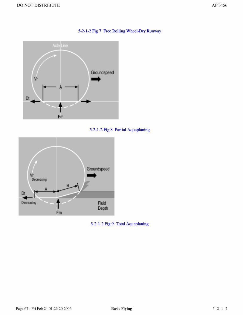
5-2-1-2 Fig 7 Free Rolling Wheel-Dry Runway
5-2-1-2 Fig 8 Partial Aquaplaning
5-2-1-2 Fig 9 Total Aquaplaning
5-2-1-2 Fig 7 Free Rolling Wheel-Dry Runway
5-2-1-2 Fig 8 Partial Aquaplaning
5-2-1-2 Fig 9 Total Aquaplaning
DO NOT DISTRIBUTE AP 3456
Page 67 : Fri Feb 24 01:26:20 2006 Basic Flying 5- 2- 1- 2

Factors Affecting Aquaplaning
68. Effect of Weight and Tyre Pressure. Changing the weight on the tyres appears to have little effect on the speed at which fullaquaplaning occurs. As the weight on the tyre changes so the contact area changes and the ratio of weight to area remains constant;this is essentially due to the tyre inflation pressure. It is this pressure that the hydrodynamic lift pressure must equal over the entirecontact area before total aquaplaning occurs. A simple expression based on hydrodynamic lift theory can be used to predict fullaquaplaning speed; this is:
V = 8.6pP (lb/in
2)
or V = 33pP (bars)
where V = full aquaplaning speed (in knots) and P = tyre pressure in units indicated. It must be remembered however, thataquaplaning is a progressive phenomenon and significant losses in braking and directional control will occur below this speed. Onceaquaplaning has started, the wheels spin-down and stop fairly rapidly. However, if groundspeed is reduced the time for the wheels tospin-up again is much longer and aquaplaning will persist to a lower speed than that given by the formula; how much lower dependsupon the surface texture.
69. Water Depth and Runway Surface. The actual depth of water required to initiate full aquaplaning depends on surface texture.Trials have shown that when puddles form to a depth of as little as 1 - 2 mm there is a potential risk of aquaplaning.
5-2-1-2 Fig 4a Technique 1
DO NOT DISTRIBUTE AP 3456
Page 68 : Fri Feb 24 01:26:21 2006 Basic Flying 5- 2- 1- 2

5-2-1-2 Fig 4b Technique 2
Basic Flying
Annex to Chapter 2 - Aircraft Arresting Systems for Airfields
Aircraft Arresting Systems
1. Aircraft arresting systems are of 2 main types: aircraft arresting barriers fitted with nets, and aircraft arresting gears fitted withhook-cables.
2. Clearance for RAF aircraft to use an arresting system is given in the aircraft Release to Service, and is detailed in the AircrewManual and appropriate Flight Reference Cards.
DO NOT DISTRIBUTE AP 3456
Page 69 : Fri Feb 24 01:26:21 2006 Basic Flying 5- 2- 1- 2A

3. The types of aircraft arresting systems on particular airfields, and their location in relation to the runway, is given in En RouteSupplements and Terminal Approach Procedure charts. Also included are details of availability and appropriate cautionary noteswhere applicable.
4. Aircraft operations should normally be conducted so as to remain within the operating limitations of the relevant arrestingsystems. Proper flight planning and supervision should ensure observance; however, arresting systems are emergency devices andinevitably circumstances will arise which require an engagement which exceeds the published limitations. In such a case it would bepreferable to engage the arresting system and obtain what retardation is available, rather than to continue unchecked at high speed intoan overshoot area.
UK AIRCRAFT ARRESTING BARRIERS
Introduction
5. The arresting barriers in service are all based on the safeland system. They are the RAF Type A and B.
Principles of Operation
6. Aircraft arresting barriers in service use the same principle of operation. A barrier net, suspended between retractable stanchions,is the engaging device and is connected at each end to cables about 200m (650ft) in length which act as the purchase element. Thecables are wound around the drums of a rotary friction brake unit which consists of multiple plate disc brakes operated by pneumaticpressure stored in an air cylinder. When an aircraft engages the barrier and drags the net forward, the net breaks free from thestanchions and starts pulling the cables from the brake drums causing them to rotate. The initial rotation of the brake unit releases theair pressure stored in the cylinder which is then fed to the brakes via a pressure regulator.
Barrier Control
7. Barrier stanchions are raised and lowered by remote control from Air Traffic Control (ATC). The Type B and RAF Mk 12ABarrier Systems can be set to operate at high or low pressure for heavier or lighter aircraft. The pressure at which the barrier is set canbe controlled either from ATC or from a remote position.
Barrier Operation
8. Barriers may be in either the fully raised or lowered position. When the Miniaturized Control System for control of the airfieldlighting is installed, there is an audible alarm if the approach end barrier is raised. In addition, each barrier stanchion is fitted with aflashing red light which illuminates into the runway approach sector when the barrier is up and the runway lights on. The departureend barrier will be up or down depending upon local orders and the barrier clearance of the aircraft about to use the runway. Pilotswill be advised on the position of the barrier as part of their clearance for take-off, landing or roller landings. It is the responsibilityof the aircraft captain to ensure that this clearance is in accordance with the Release to Service of his aircraft. If a pilot intends toengage the barrier he should call “BARRIER BARRIER BARRIER” over the R/T. The controller will check that the barrier iscorrectly positioned and also alert the safety services and recovery team.
Clearance Considerations
9. Before an aircraft can be cleared to use an arresting barrier the following basic factors are considered:
a. The height of the nose and canopy of the aircraft in relation to the height of the top cable of the barrier.
b. The aircraft weight and its unstick speed (maximum mV2).
c. The size, shape and strength of the wing structure, the design of air intakes and the nature of external stores.
10. Under no circumstances should an aircraft engage a barrier for which it has not been cleared. However, when cleared, andprovided there is a suitable overrun, a pilot will not be exposed to greater danger, nor will the aircraft suffer worse damage onengagement, if the aircraft is outside the speed/weight limitations of the barrier.
DO NOT DISTRIBUTE AP 3456
Page 70 : Fri Feb 24 01:26:21 2006 Basic Flying 5- 2- 1- 2A

RAF Type A Barrier
11. The RAF Type A Barrier is shown in Fig 1. It comprises two single energy absorption units, a British Arresting Net Mk2 andtwo British Barrier Stanchions Mk 1. The stanchions are steel A frames pivoted by self-contained electric motors and gear units. Thetop portion of each stanchion is telescopic, permitting the height of the stanchions to be adjusted between 5.3m (17ft 6in) and 6.2m(20ft 6in) in height. The net, when raised should be 3.66m (12ft) high at the centre. the maximum engagement velocity is 120kt andthe system runout is 220m (720ft).
RAF Type B Barrier
12. The RAF Type B barrier, is also illustrated at Fig 1. It comprises four dual pressure absorption units and the same net andstanchions as the Type A. The dual pressure absorption units of the Type B barrier are required for airfields which operate theheavier types of aircraft needing a high braking force. The brakes can be set at high or low pneumatic pressure. The low pressuregives similar braking to the Type A barrier. The engagement velocity and runout distance are the same as for the Type A barrier.
5-2-1-2A Fig 1 Arresting Barrier Systems - Type A and Type B
UK AIRCRAFT ARRESTING GEAR
Introduction
13. An aircraft arresting gear is a device to engage hook equipped aircraft. Normally it consists of a hook-cable stretched across therunway and held above the surface by supports. The cable is attached to the purchase element, a nylon tape wound on the reel of anenergy absorbing unit mounted on each side of the runway. In order to align the elements of the system, the purchase element ispassed through sheaves.
14. The Rotary Hydraulic Arrester Gear (RHAG) Mk1 is intended to arrest hook-equipped aircraft which, through some fault, couldnot otherwise be stopped safely on the available runway. Within speed and weight limitations RHAG Mk1 is designed to cater foremergencies which may arise either on take-off or landing, and subject to aircraft and installation considerations, the arresting gearcan be engaged from either direction.
RHAG Mk 1 Description
15. The RHAG Mk1 installation consists of an Energy Absorber Unit (EAU) placed each side of the runway, runway edge sheavesand a hook-cable. The layout of a RHAG installation is shown in Fig 2.
16. The EAU, when engaged, pays out nylon purchase tapes through the runway edge sheaves. The purchase tapes are connected toa single length of steel wire rope which is the hook-cable. In the “up” position the cable is stretched across the runway and supportedby 15cm (6 inch) diameter, rubber grommets. The hook-cable is therefore at a nominal height of 76mm (3 inches) in the supported
DO NOT DISTRIBUTE AP 3456
Page 71 : Fri Feb 24 01:26:21 2006 Basic Flying 5- 2- 1- 2A

position. At some locations the supports are replaced by bow-spring devices which are flush fitted into the running surface. It ispossible to lift the wire up into the tensioned and supported position or to place it in the down, tensioned and unsupported position, byremote control. This is known as the Retractable Hook-cable Support System (RHCSS). In addition some systems are fitted withRetractable Runway Edge Sheaves (RRES) so that the sheaves do not present an obstruction for aircraft not requiring the RHAG.
17. Each EAU contains an identical brake unit and retrieve system. The brake unit consists of a vaned impeller placed between fixedstator blades in a fluid housing filled with water/glycol mixture. The shaft of the rotor is mounted vertically and is splined to thepurchase tape drum. The drum is connected to the electrically powered retrieve system by a spring-loaded pre-tensioning device. Onengagement, the pre-tensioning mechanism is overridden. Rotation of the impeller in the fluid housing absorbs the kinetic energy ofthe aircraft and the aircraft is arrested. During the arrest, the purchase tape is rotating the drum by continuously reducing the momentarm as the drum is unwound, this helps to provide a near constant force on the aircraft hook throughout the arrest.
5-2-1-2A Fig 2 RHAG Mk1 - Layout
18. RHAG Mk1 is designed to provide a constant run-out, nominally 366m (1200ft), regardless of aircraft entry speed or weight; theslower the entry speed the less resistance to impeller rotation and vice versa. The run-out will vary due to changes in the stretch of thepurchase tapes with different entry conditions and will be slightly extended at some installations with wide RRES spacing. It may benecessary to limit the run-out to prevent conflict with other airfield installations and this can be achieved by the use of shorterpurchase tapes. However, the effect of a reduced run-out is to increase the stress on the aircraft hook and for this reason few RHAGsystems are equipped with shorter tapes.
Trampling Clearance
19. Hook-cable Up. In the up position the hook-cable may rebound when an aircraft rolls over it. There is therefore a chance thatlow slung stores in the structure of the aircraft may be damaged by either the hook-cable or its supports. Also with some types ofbogey undercarriage there is a chance that the hook-cable could become entangled with the aircraft's wheels. The best tramplingspeeds for aircraft are promulgated through normal Release to Service channels or in Aircrew Manuals for individual aircraft.
20. Hook-cable Down. The hook-cable will not rebound on being trampled if the hook-cable support system is retracted to allow thetensioned cable to lie flush with the runway surface. All Service aircraft are cleared to taxi, land and take off over tensionedunsupported RHAG hook-cables.
DO NOT DISTRIBUTE AP 3456
Page 72 : Fri Feb 24 01:26:21 2006 Basic Flying 5- 2- 1- 2A

Basic Flying
Chapter 3 - Stalling and Spinning
STALLING
Introduction
1. An aircraft stalls when the smooth flow of the air over its wings changes to a turbulent flow and the lift decreases. As this mayhappen suddenly, a pilot must be able to recognize the approach of a stall and know the recovery action for minimum loss of height.
Stalling Characteristics
2. The stalling characteristics of an aircraft should be investigated during aircraft familiarization. In general, stalling follows acommon pattern. As speed is reduced, warning of the impending stall is given in the form of buffeting which can vary from beingfairly severe to almost imperceptible, depending on the aircraft type and configuration. The buffet may start at some 5-15 kt beforethe stall and usually increases in strength as the stall is approached. On some aircraft an artificial indication of the approaching stallis provided and one method of doing this is to make the whole control column, or an inset portion of the handgrip, vibrate strongly ata preset speed close to the stall.
3. On all aircraft, as speed is reduced the controls become less effective and larger movements are needed to correct or achieve agiven displacement of the aircraft. On aircraft without power-operated controls, the feel of the controls becomes noticeably slack andtheir effectiveness decreases as the stall approaches.
4. At the stall, either wing and/or the nose may drop suddenly and to a varying degree. With power on, the stalling speed is lower,the nose-up attitude of the aircraft at the stall is more pronounced and any wing-dropping tendency is aggravated. The lower stallingspeed is due to the vertical component of the upwards-inclined thrust line which provides an additional lifting force and so allowslevel flight at a lower speed. Propeller slipstream over the mainplane also produces additional lift. The greater the power used, thelower the stalling speed.
5. On many types of aircraft, when the initial wing or nose-drop occurs, the control column may not be fully back and any furtherbackward movement in these circumstances may aggravate any wing-dropping tendency and tend to induce a spin. In general,recovery should be made when the initial nose or wing-drop occurs.
6. If an unintentional spin occurs when stalling with the flaps and undercarriage down, consideration should be given to raisingthem to ensure that they do not affect the recovery and to minimize damage due to excessive speed. The Aircrew Manual will giveappropriate advice if aircraft handling or safety are likely to be affected.
Stalling in Manoeuvres
7. If an attempt is made to change the flight path in the pitching plane too quickly, eg by turning at too high a rate or by recoveringfrom a dive too sharply, a stall known variously as an accelerated or g stall, or less accurately as a high speed stall, may occur. Thislast term is not altogether appropriate since the speed may be only a few knots above the level flight stalling speed when the controlcolumn is moved back to apply the g.
8. Warning of the approach of an accelerated stall is given by airframe buffeting which increases in intensity as the stalling angle isapproached. The stick force and control effectiveness are proportional to the IAS at which the stall occurs, which may be any speedof which the aircraft is capable.
9. The manoeuvres described in para 7 involve accelerations in the pitching plane and result in an increased loading on the aircraft.Although the accelerated stall occurs at the same angle of attack as the normal stall, the IAS at which it occurs is roughly equivalentto the level flight stalling IAS multiplied by the square root of the load factor. For example, during a 60° banked turn (ie, with a loadfactor of 2) an aircraft having a normal stalling IAS of 100 kt would stall at an IAS of 100 × 1.41 kt, ie 141 kt.
DO NOT DISTRIBUTE AP 3456
Page 73 : Fri Feb 24 01:26:21 2006 Basic Flying 5- 2- 1- 3
10. At the lowest speeds, even slight g loading is sufficient to cause a stall, particularly on aircraft with high wing loadings. Inconsequence, steep approaches for landing should not normally be made on these aircraft as the large backward movement of thecontrol column required to round-out for the landing may apply sufficient g to stall the aircraft at the low speed used on theapproach.
11. During dives and dive recoveries at low altitudes, such as those used in air-to-ground armament practices, ample height must beallowed for recovery. Over-concentration on the aiming problem can result in insufficient height for normal recovery and if, in thesubsequent attempt to recover, excessive g is applied, the aircraft will stall and possibly flick into a spin. If the speed is high, eventhough the stalling angle may not be reached, the g threshold of the pilot and/or limitation of the aircraft may be exceeded.
12. Any pitch-up tendencies possessed by a swept-wing aircraft are exaggerated when enough g is applied to stall the aircraft in amanoeuvre. The higher the g applied to cause the stall, the stronger is the pitch-up and the consequent, unavoidable increase in gbefore the motion can be checked by a forward movement of the control column. This resultant g caused by pitch-up can be serious athigh IAS and low altitude because a high initial g loading is needed to promote pitch-up under these conditions and any temporaryincrease might exceed the g limitations. However, the g limitations placed on such aircraft do take this possibility into account and,unless the g limitation is exceeded, pitch-up should not occur on an aircraft with its centre of gravity within the specified limits. Atthe highest altitudes, although forming an operational weakness, pitch-up does not usually result in a serious increase in g as both theinitiating g and the resultant g are low as a result of the reduced IAS at these altitudes.
13. When the stall occurs in a turn, depending on which wing stalls and drops first, the aircraft tends to roll either into or out of theturn. During recovery from a dive, either wing may drop. In certain aircraft the wing-drop is sudden and may be severe. If thecontrol column is held back the aircraft may flick roll which, at high speed, can cause severe overstressing.
14. Recovery from any stage of an accelerated stall is made by moving the control column forward until the buffeting stops.
Stall Recovery
15. Stall recovery must be made as quickly and decisively as possible with a minimum loss of height, using full power.
16. Straight-Wing Aircraft. The recommended recovery action is to ease the control column forward far enough to unstall the wingsand to apply up to full power simultaneously, as quickly as engine limitations permit. Care must be taken not to move the controlcolumn too far forward otherwise unnecessary height will be lost. If sufficient thrust is available it should only be necessary to movethe control column forward slightly, as the thrust will be adequate to accelerate the aircraft to a higher speed and, as stated at para 4,the use of power reduces the stalling speed. If a wing drops, the recovery action given in the Aircrew Manual should be taken. Theaircraft must be eased gradually out of the dive following recovery; any attempt to force a return to level flight may induce a g stalland cause a further loss of height.
17. Swept-Wing Aircraft. The general stalling characteristics of aircraft with swept-back leading edges may differ considerably fromthose of straight-wing types. The Release to Service and Aircrew Manual should be consulted to check minimum permitted flyingspeed and whether or not the aircraft is cleared for stalling practice. As on a straight-wing aircraft, as the stall is approached it isusual for the buffet to be felt, increasing in strength as the stall approaches, although the amount of buffet may be barely discernablein some cases. On all swept-wing types it is most important to recover as soon as the initial wing or nose drop occurs. Advice onhandling during the approach to the stall, the stall, and stall recovery can be found in the aircrew manual.
SPINNING
Introduction
18. The following paragraphs are general remarks only on spinning; Aircrew Manuals should always be consulted for entry andrecovery action before spinning an unfamiliar aircraft.
19. The spin is not a normal manoeuvre: it is the result of yawing or rolling at the point of stall. As it is possible to enter a spinthrough mishandling the controls during aerobatics, steep turns and other quite normal manoeuvres, the pilot must be able torecognize a spin and recover promptly. This is done by practising spinning and spin recovery on suitable types of aircraft so that thepilot becomes accustomed to the sensation of spinning and quickens his assessment of the change of attitude and motion of theaircraft. The stick forces experienced during a spin may be high on some aircraft, necessitating the use of both hands to effectrecovery; on other aircraft the forces may be so low that little or no effort is required to move the control column. In certain cases
DO NOT DISTRIBUTE AP 3456
Page 74 : Fri Feb 24 01:26:21 2006 Basic Flying 5- 2- 1- 3
considerable snatching occurs on the control column and some strength is needed to hold the control column in a desired position.During a rapid spin, or if a pilot is unaccustomed to spinning, considerable disorientation and mental confusion should be anticipated;instances have occurred when experienced pilots have been convinced of the direction of spin only to be proved wrong, and whatappears to be correct recovery action in such cases only prolongs the spin.
Airmanship
20. Before practising spinning, the following checks should be carried out:
a. Before take-off, ensure that:
(1) The exercise is permitted and authorized, and that correct entry and recovery action for the type are known.
(2) Full control deflections can be made and that the neutral positions are known.
b. In the air, before entering the spin:
(1) Carry out the pre-aerobatic checks for the aircraft type.
(2) Ensure that the weather conditions are suitable.
(3) Inform the pupil or passenger of the intended manoeuvre.
Abandoning a Spinning Aircraft
21. If a pilot considers that his height is insufficient to recover from a spin, the aircraft should be abandoned. Minimum heights forabandonment are specified in Aircrew Manuals and Flying Order Books.
Advanced Flying
Chapter 1 - Aerobatics
Introduction
1. Although aerobatics, in themselves, are of little operational value, they form an essential part of a pilot’s training because:
a. They increase confidence, judgement, flying ability and teach the quickest methods of recovering from unusual attitudes orafter loss of control.
b. They form the basis of some tactical manoeuvres.
c. They harden and accustom the pilot to the high strains imposed on him in combat flights.
d. They give the pilot a means of assessing control qualities of any particular aircraft.
2. The regulations concerning aerobatics are designed to safeguard life and property and should be adhered to at all times; they arelaid down in JSP 318 (Military Flying Regulations).
Airmanship
3. Before starting any aerobatics, in addition to observing the regulations, the following checks should be carried out:
NOTE:If fuel is carried in overload tanks, ensure the aircraft is cleared for aerobatics with fuel in these tanks.
DO NOT DISTRIBUTE AP 3456
Page 75 : Fri Feb 24 01:26:21 2006 Advanced Flying 5- 2- 2- 1

a. Height - sufficient to perform the complete manoeuvre without descending below the prescribed minimum.
b. Airframe - check that flaps and undercarriage are UP, airbrakes tested and IN.
c. Security - all equipment and loose articles should be stowed and the seat harness locked and tight.
d. Engine - all temperatures and pressures normal and fuel sufficient for the exercise.
e. Location - make sure that the aerobatics will take place in air space clear of Active airfields, Built-up areas and Controlledairspace. To avoid the possibility of getting lost, select a suitable landmark and keep a position check on it.
f. Look-Out - keep well clear of all other aircraft and cloud, vertically and horizontally throughout the exercise.
Engine Handling
4. All throttle movements should be made smoothly, especially with jet engine aircraft. In piston engine aircraft the throttle shouldbe closed if the engine cuts after negative loading. (In some piston engine aircraft it is necessary to close the throttle before theinverted position is reached to prevent a rich cut). Full power should be used only if the particular manoeuvre requires it.
Vertical Attitudes
5. If at any time the aircraft inadvertently reaches a vertical or near-vertical nose-up attitude at a low IAS, subsequent mishandlingcan cause a spin. To recover from this attitude use the technique recommended in the Aircrew Manual.
BASIC AEROBATICS
Recommended Speeds
6. Aircrew Manuals detail the recommended speeds for the standard aerobatics. However, as confidence and skill is gained somemanoeuvres may be performed at lower speeds.
5-2-2-1 Fig 1 Loop
DO NOT DISTRIBUTE AP 3456
Page 76 : Fri Feb 24 01:26:21 2006 Advanced Flying 5- 2- 2- 1

5-2-2-1 Fig 2 Slow Roll
Loop
7. In the loop, shown in Fig 1, the aircraft starts from the straight and level attitude and returns to it, having flown through 360° inthe vertical plane. Positive loading should be maintained throughout, but this varies in amount depending on the position in the loop.The minimum speed necessary depends on the speed lost in the first half of the manoeuvre and that required to maintain control at thetop of the loop.
8. A loop should preferably be flown along a line feature to keep straight. If necessary a shallow dive can be made to gain therequired airspeed. During the dive the aircraft should not be retrimmed but the nose-up tendency should be checked by forwardpressure on the control column. When at the required airspeed the nose is raised gently to maintain a constant rate of pitchthroughout the whole loop. When in the inverted position the speed will be low (even below the level flight stalling speed) and careshould be taken not to stall the aircraft. During the whole of the manoeuvre rudder should be used to prevent yaw and the aileronsused to keep the wings level. On aircraft with manually-operated controls, and power-operated controls with “q” feel, the stick forcesrequired to maintain the loop decrease to a minimum at the top when the speed is low. However, with power-operated controls wherethe artificial stick force is proportional to stick movement, the larger stick movements at the lower speeds at the top of a loop result ina greater stick force at this point.
Slow Roll
9. An aircraft is said to roll when it is rotated round its longitudinal axis through 360° see Fig 2. This definition applies to all typesof roll. The speed at which a roll is performed is not important provided it allows a good margin above the stalling speed and that it iscarried out at a safe height. The higher the speed, the easier it is to control the roll and less height is lost. If the engine runs wheninverted, speed is still less important, for the power assists in maintaining speed and height and controlling the attitude. The rate ofroll depends on the amount of aileron used, the speed at which the roll is started and the type of aircraft.
10. To fly a slow roll, a point should be chosen on the horizon on which to keep straight. At the required speed the nose should be
DO NOT DISTRIBUTE AP 3456
Page 77 : Fri Feb 24 01:26:21 2006 Advanced Flying 5- 2- 2- 1
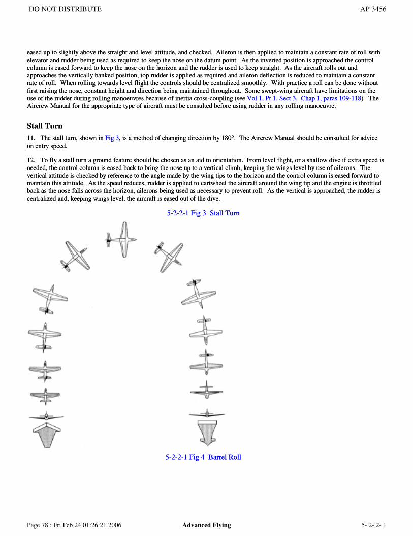
eased up to slightly above the straight and level attitude, and checked. Aileron is then applied to maintain a constant rate of roll withelevator and rudder being used as required to keep the nose on the datum point. As the inverted position is approached the controlcolumn is eased forward to keep the nose on the horizon and the rudder is used to keep straight. As the aircraft rolls out andapproaches the vertically banked position, top rudder is applied as required and aileron deflection is reduced to maintain a constantrate of roll. When rolling towards level flight the controls should be centralized smoothly. With practice a roll can be done withoutfirst raising the nose, constant height and direction being maintained throughout. Some swept-wing aircraft have limitations on theuse of the rudder during rolling manoeuvres because of inertia cross-coupling (see Vol 1, Pt 1, Sect 3, Chap 1, paras 109-118). TheAircrew Manual for the appropriate type of aircraft must be consulted before using rudder in any rolling manoeuvre.
Stall Turn
11. The stall turn, shown in Fig 3, is a method of changing direction by 180°. The Aircrew Manual should be consulted for adviceon entry speed.
12. To fly a stall turn a ground feature should be chosen as an aid to orientation. From level flight, or a shallow dive if extra speed isneeded, the control column is eased back to bring the nose up to a vertical climb, keeping the wings level by use of ailerons. Thevertical attitude is checked by reference to the angle made by the wing tips to the horizon and the control column is eased forward tomaintain this attitude. As the speed reduces, rudder is applied to cartwheel the aircraft around the wing tip and the engine is throttledback as the nose falls across the horizon, ailerons being used as necessary to prevent roll. As the vertical is approached, the rudder iscentralized and, keeping wings level, the aircraft is eased out of the dive.
5-2-2-1 Fig 3 Stall Turn
5-2-2-1 Fig 4 Barrel Roll
DO NOT DISTRIBUTE AP 3456
Page 78 : Fri Feb 24 01:26:21 2006 Advanced Flying 5- 2- 2- 1
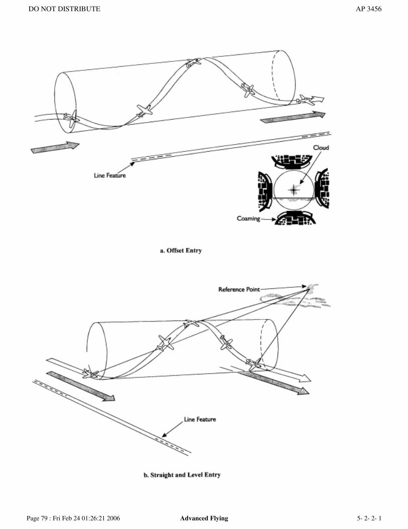
DO NOT DISTRIBUTE AP 3456
Page 79 : Fri Feb 24 01:26:21 2006 Advanced Flying 5- 2- 2- 1

Barrel Roll
13. Barrel rolls are illustrated in Fig 4. In the barrel roll the aircraft is made to rotate round its longitudinal axis, but the flight path ishelical; height and direction change as the aircraft is flown round the outside of an imaginary barrel. The manoeuvre is thoroughlyco-ordinated, positive g being applied throughout the entire roll and rudder used to prevent slip or skid. The manoeuvre is normallyflown with a horizontal axis and when viewed from the cockpit, the nose of the aircraft merely appears to describe a circle about a realor imaginary point on the horizon.
14. There are two methods of entering a barrel roll:
a. Offset Entry. A reference point just above the horizon is selected and an imaginary circle drawn around it. The aim is totrack the nose of the aircraft around the circle. Starting from straight and level the aircraft is flown in a descending turn using 45°
of bank to intercept the circle in the 4/8 o’clock position depending on the direction of the intended roll. A rolling pitch-up isstarted, using 3-4‘g’, aiming to be wings level at the bottom of the manoeuvre just before the nose comes up through the horizon.The roll rate is maintained so that at the top of the barrel roll, wings level inverted is achieved just as the nose comes downthrough the horizon. The amount of aileron needed is generally small compared to the amount of elevator required. The amountof control deflection required will vary according to the changing speed and rudder is needed to maintain balance in propellerdriven aircraft. If the nose tracks inside the imaginary circle then the roll rate is too high. In the second half of the roll there is atendency to allow the pitch and roll rates to increase due to increased control effectiveness as speed increases.
b. Entry From Straight and Level. From straight and level the barrel roll is entered at the 6 o’clock position. The required entryspeed is slightly higher than for the offset entry. A reference point in line with the wing tip should be selected. The aircraft ispitched up at about 3-4g and rolled using a small amount of aileron. A constant pitch rate is maintained and the roll is adjustedso that the nose appears to pass through the reference point wings level and inverted at the top of the manoeuvre. The roll andpitch are maintained to the straight and level, flying along the line feature, with the pull being adjusted to achieve the requiredbase level. The reference point should re-appear on the wing tip.
Half Roll off the Top of a Loop
15. The half roll off the top of a loop consists of the first half a loop followed by half of a slow or barrel roll, the aircraft reversingdirection and gaining height. A little more speed is required than for the loop so that sufficient speed is available for the half roll, seeFig 5.
5-2-2-1 Fig 5 Half Roll off Top of a Loop
DO NOT DISTRIBUTE AP 3456
Page 80 : Fri Feb 24 01:26:21 2006 Advanced Flying 5- 2- 2- 1
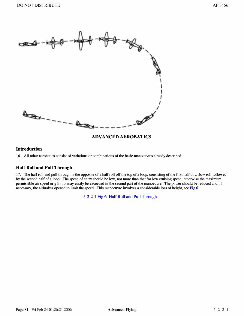
ADVANCED AEROBATICS
Introduction
16. All other aerobatics consist of variations or combinations of the basic manoeuvres already described.
Half Roll and Pull Through
17. The half roll and pull through is the opposite of a half roll off the top of a loop, consisting of the first half of a slow roll followedby the second half of a loop. The speed of entry should be low, not more than that for low cruising speed, otherwise the maximumpermissible air speed or g limits may easily be exceeded in the second part of the manoeuvre. The power should be reduced and, ifnecessary, the airbrakes opened to limit the speed. This manoeuvre involves a considerable loss of height, see Fig 6.
5-2-2-1 Fig 6 Half Roll and Pull Through
DO NOT DISTRIBUTE AP 3456
Page 81 : Fri Feb 24 01:26:21 2006 Advanced Flying 5- 2- 2- 1

Upward or Vertical Roll
18. The terms upward or vertical roll include all rolls which are made in a climbing or steep nose-up attitude. Such rolls are done inthe same way as a normal roll but, since the plane of the roll is inclined, considerably more speed and power is required; some aircraftdo not have enough power to perform them satisfactorily. The manoeuvre is a difficult one to perform accurately unless there areclouds above to use as a guide to direction. The more nearly vertical the roll, the less is the amount of rudder required. For a verticalroll the attitude is best judged by checking that the chord of the wing cuts the horizon at right-angles.
Aileron Turn
19. The aileron turn is a roll flown vertically downwards. It may be started from a half roll or from the second half of a loop; ineither case it is started when the aircraft is pointing vertically down. In this manoeuvre speed increases very rapidly and considerableheight is lost. Power should be reduced and airbrakes opened to control the speed, if necessary. An aileron turn is shown in Fig 7.
5-2-2-1 Fig 7 Aileron Turn
DO NOT DISTRIBUTE AP 3456
Page 82 : Fri Feb 24 01:26:21 2006 Advanced Flying 5- 2- 2- 1
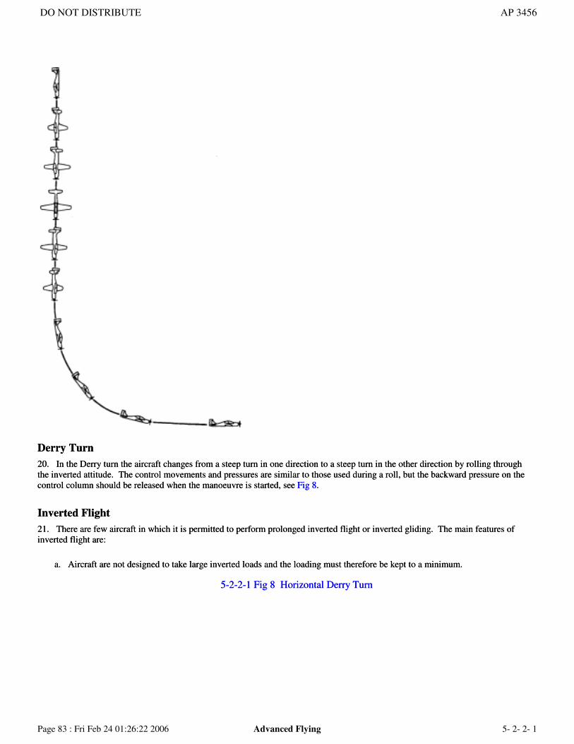
Derry Turn
20. In the Derry turn the aircraft changes from a steep turn in one direction to a steep turn in the other direction by rolling throughthe inverted attitude. The control movements and pressures are similar to those used during a roll, but the backward pressure on thecontrol column should be released when the manoeuvre is started, see Fig 8.
Inverted Flight
21. There are few aircraft in which it is permitted to perform prolonged inverted flight or inverted gliding. The main features ofinverted flight are:
a. Aircraft are not designed to take large inverted loads and the loading must therefore be kept to a minimum.
5-2-2-1 Fig 8 Horizontal Derry Turn
DO NOT DISTRIBUTE AP 3456
Page 83 : Fri Feb 24 01:26:22 2006 Advanced Flying 5- 2- 2- 1

b. The aircraft responds normally when the controls are moved, but the movement of the aircraft relative to the horizon will bethe reverse of that for the same control movements in normal flight. For example, to make a descending turn to the left (ie in aclockwise direction), the control column should be eased backwards and to the pilot’s right to lower the nose and apply therequired degree of bank; right rudder should be applied to counteract slip.
c. During inverted flight at a given speed, the lift coefficient is much lower resulting in an increased stalling speed. Because ofthe lower lift coefficient the wing must be set at a higher angle of attack than for the same speed in normal flight; see Fig 9.
d. Due to the lower wing efficiency and the high stalling speed, the gliding speed is higher when inverted; about one and a thirdtimes the normal gliding speed is generally suitable.
e. The aircraft may be sensitive laterally because any dihedral now has a destabilizing effect.
5-2-2-1 Fig 9 Inverted Flight
DO NOT DISTRIBUTE AP 3456
Page 84 : Fri Feb 24 01:26:22 2006 Advanced Flying 5- 2- 2- 1
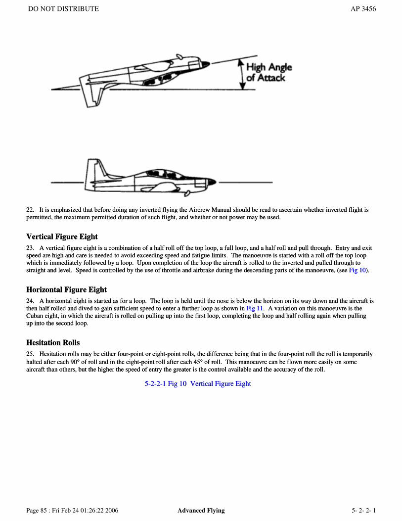
22. It is emphasized that before doing any inverted flying the Aircrew Manual should be read to ascertain whether inverted flight ispermitted, the maximum permitted duration of such flight, and whether or not power may be used.
Vertical Figure Eight
23. A vertical figure eight is a combination of a half roll off the top loop, a full loop, and a half roll and pull through. Entry and exitspeed are high and care is needed to avoid exceeding speed and fatigue limits. The manoeuvre is started with a roll off the top loopwhich is immediately followed by a loop. Upon completion of the loop the aircraft is rolled to the inverted and pulled through tostraight and level. Speed is controlled by the use of throttle and airbrake during the descending parts of the manoeuvre, (see Fig 10).
Horizontal Figure Eight
24. A horizontal eight is started as for a loop. The loop is held until the nose is below the horizon on its way down and the aircraft isthen half rolled and dived to gain sufficient speed to enter a further loop as shown in Fig 11. A variation on this manoeuvre is theCuban eight, in which the aircraft is rolled on pulling up into the first loop, completing the loop and half rolling again when pullingup into the second loop.
Hesitation Rolls
25. Hesitation rolls may be either four-point or eight-point rolls, the difference being that in the four-point roll the roll is temporarilyhalted after each 90° of roll and in the eight-point roll after each 45° of roll. This manoeuvre can be flown more easily on someaircraft than others, but the higher the speed of entry the greater is the control available and the accuracy of the roll.
5-2-2-1 Fig 10 Vertical Figure Eight
DO NOT DISTRIBUTE AP 3456
Page 85 : Fri Feb 24 01:26:22 2006 Advanced Flying 5- 2- 2- 1

5-2-2-1 Fig 11 Horizontal Figure Eight5-2-2-1 Fig 11 Horizontal Figure Eight
DO NOT DISTRIBUTE AP 3456
Page 86 : Fri Feb 24 01:26:22 2006 Advanced Flying 5- 2- 2- 1

5-2-2-1 Fig 4a Offset Entry
5-2-2-1 Fig 4b Straight and Level Entry
Advanced Flying
5-2-2-1 Fig 4a Offset Entry
5-2-2-1 Fig 4b Straight and Level Entry
Advanced Flying
DO NOT DISTRIBUTE AP 3456
Page 87 : Fri Feb 24 01:26:22 2006 Advanced Flying 5- 2- 2- 2

Chapter 2 - Flying in Turbulence
Introduction
1. Turbulence may be defined as perturbations in the atmosphere which disturb the smooth progress of an aircraft through it. Theseperturbations may be produced by terrain or obstacles, local convection, artificial disturbances or natural phenomena. The effectsrange from short sharp bumps to much longer smooth up and down draughts which may be several miles long.
2. Penetration of severe turbulence can be hazardous and aircrew should be aware of the types of turbulence which may be met, andof the best techniques for flight in turbulent conditions. The following paragraphs deal with the effects and causes of the varioustypes of turbulence and with the recommended techniques for flying in them.
EFFECTS OF TURBULENCE
General
3. The effects of turbulence may be dealt with under four headings:
a. Structural.
b. Handling.
c. Physiological.
d. Overall considerations.
Structural Effects
4. Sharp edged gusts may be encountered which can impose large structural loads on an airframe. The severity of a given gust willincrease with the aircraft’s rate of traverse of the gust and thus with its TAS. Since the structural load imposed on an aircraft is adirect function of g loading and TAS, airspeed is the most important single factor to consider from the structural viewpoint whenflying in turbulence.
5. The basic design strength of the aircraft is a vital factor in deciding what level of turbulence is acceptable to a particular type ofaircraft. Fighter and most training aircraft are sufficiently strong to withstand any gust they may meet in flight, although handling inturbulence may then be a problem. Large transport and similar types of aircraft are built to much lower standards of structuralstrength and should not be exposed to severe turbulence except in emergency. Although the aircraft may not be damaged as a directresult of a gust, it may well be broken by a combination of disturbance due to turbulence and pilot control inputs to correct thedisturbance. A number of catastrophic structural failures to large transport aircraft have occurred as a result of the aircraft beingdisturbed by a large gust, entering a steep dive and being broken up during the recovery by excessive g and airspeed.
Handling Effects
6. The effects on an aircraft’s handling in turbulence are of primary interest to the pilot. He needs to be able to maintain a desiredflight path (within certain limits) and, above all, to contain the aircraft’s attitude in pitch and roll.
7. Thus, the pilot needs to fly the aircraft in turbulence at an airspeed giving him sufficient margin over the stall and sufficientcontrol power to restrain the aircraft’s attitude excursions, but at a sufficiently low speed to ensure that he does not overstress theairframe or lose control. The Aircrew Manual will give specific type advice.
Physiological Effects
8. The physiological effects of turbulence are caused by the rapid and frequent reversals of motion imposed on the human body.The most common effects are fatigue, nausea, and in extreme cases, deterioration of vision. Fatigue is generally aggravated by aprolonged period of flight in severe turbulence, particularly when the physical forces needed to control the aircraft are large. Nauseais a well-known phenomenon and is generally more of a problem to passengers than aircrew. Vision can deteriorate quite markedly in
DO NOT DISTRIBUTE AP 3456
Page 88 : Fri Feb 24 01:26:22 2006 Advanced Flying 5- 2- 2- 2
severe turbulence, and particularly so when the turbulence excites an aircraft structural mode of vibration. In such cases it can bequite difficult to read the instrument panel and prolonged instrument flight becomes hazardous and tiring.
Overall Considerations
9. The overall effects of turbulence are an increased workload in flying the aircraft, the presence of structural and control hazardsand, not least, discomfort. As already mentioned the most important single feature in turbulence flight is TAS, and the AircrewManuals for most aircraft contain a recommended best speed. Where no specific speed is recommended a guide can be obtained formost aircraft by multiplying the stalling speed with flaps and undercarriage retracted by 1.6. For light aircraft, a penetration speed ofabout twice the stalling speed should be used.
TYPES OF TURBULENCE
General
10. The main types of turbulence encountered are:
a. Convective.
b. Wind Shear
c. Ground effect.
d. Clear air.
e. Turbulence caused by aircraft wakes.
Convective Turbulence
11. Thunderstorm Hazards. General convective turbulence is encountered in unstable air masses and is at its most severe in andaround cumulo-nimbus or storm clouds. Vertical currents of 5,000 fpm may be encountered and rapid gust reversal may be met inand out of cloud. Flight through cumulo-nimbus clouds should be avoided whenever possible since penetration of storms will exposethe aircraft to the risk of damage through hail or lightning strikes, to the possibility of structural damage due to overstressing in severeturbulence and to severe ice accretion, affecting airframe and engines. In aircraft fitted with storm warning radar it may be possible toavoid flight directly through storm cells but it should be remembered that turbulence, hail and lightning may also be present in thevicinity of storms. Without radar, identification of cumulo-nimbus clouds is often difficult, particularly where storms are embeddedin more general cloud layers and pilots may sometimes find themselves in, or near, a cumulo-nimbus cloud where some or all of thefollowing features may be encountered.
5-2-2-2 Fig 1 Hail Damage
DO NOT DISTRIBUTE AP 3456
Page 89 : Fri Feb 24 01:26:22 2006 Advanced Flying 5- 2- 2- 2

a. Hail. Hail is encountered in the more severe storms, particularly in the midwest of the USA, the Mediterranean and in certaintropical areas, where monsoon storms are encountered. The size of hail stones varies greatly, and is generally a function of thestrength of the vertical currents and thus of the length of time the hail stones have been supported by these currents. Damagesustained by aircraft in large hail can be very severe (see Fig 1) and is clearly a function of TAS and hail stone size. To minimizethe risk of hail damage, the penetration of likely areas should be made as far below the freezing level as possible. Flight belowthe ‘anvil’ of a thunderstorm is one of the most likely areas for hail damage and should be avoided as stringently as thepenetration of an actual storm cell.
b. Icing. Thunderstorms frequently contain large quantities of super-cooled water droplets. Thus, aircraft flying at outside airtemperatures below 0°C are likely to accumulate ice. Airframe icing, though it may accumulate at a high rate, is likely to belimited since the horizontal extent of storms is generally small. Engine damage, due to ice ingestion, to axial-flow turbines islikely to be a more serious problem, and engine anti-icing systems should be used as directed in Aircrew Manuals. Ingress ofwater or icing of pitot/static systems is a serious hazard in storms containing large quantities of moisture. In the event of loss ofpressure instruments, the aircraft attitude should be maintained until clear air is reached or the pitot/static system clears again.The static system should be treated as suspect for the remainder of the flight.
c. Lightning. There is always the possibility of a lightning strike when flying in the vicinity of a thunderstorm. A lightningstrike can be a very unpleasant experience, usually consisting of a bright flash on discharge, an explosive noise and a smell ofburning. Generally, damage to the aircraft is confined to small burns near the extremities or near aerials. There is often no visualevidence of a strike, but magnetic compasses may be badly affected and should be checked for accuracy after a suspected strike.In extreme cases, disturbance of certain aircraft electrical or electronic systems may be encountered. In the vicinity of lighting,cockpit lighting should be turned up fully, even in daylight, and, where two pilots are carried, one should wear dark glasses or avizor to minimize the effects of dazzle.
5-2-2-2 Fig 2 Wind Shear Pattern Beneath a Thunderstorm
DO NOT DISTRIBUTE AP 3456
Page 90 : Fri Feb 24 01:26:22 2006 Advanced Flying 5- 2- 2- 2
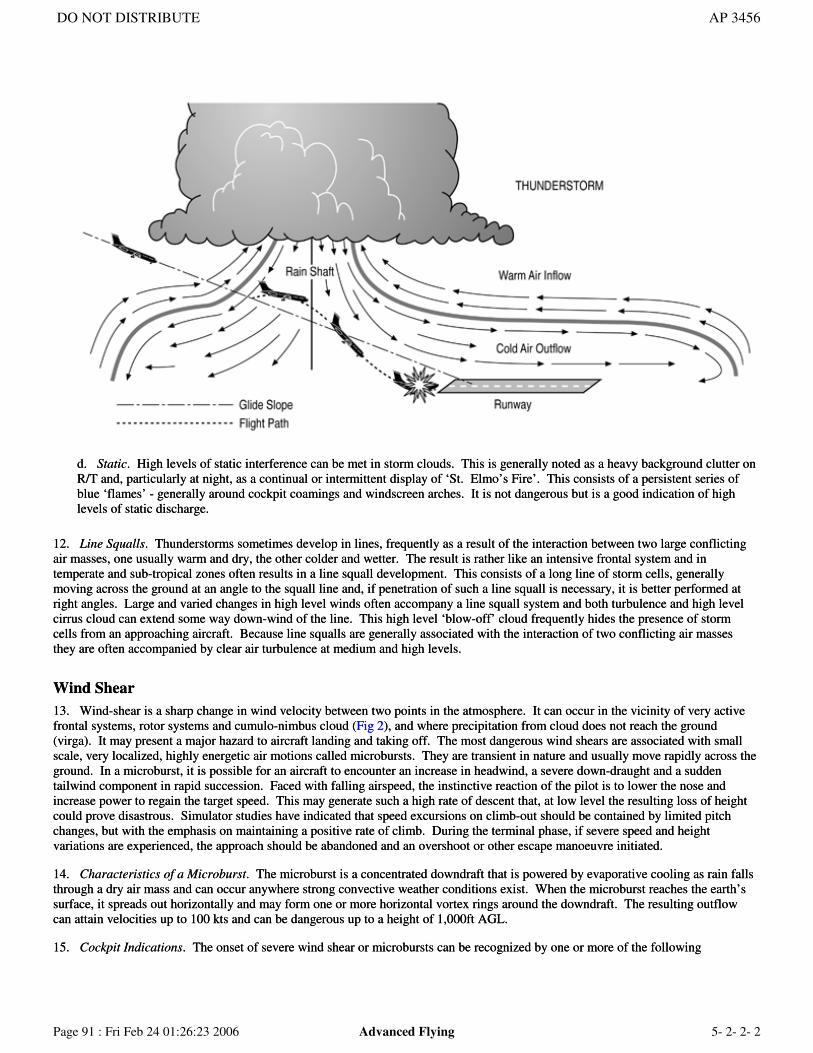
d. Static. High levels of static interference can be met in storm clouds. This is generally noted as a heavy background clutter onR/T and, particularly at night, as a continual or intermittent display of ‘St. Elmo’s Fire’. This consists of a persistent series ofblue ‘flames’ - generally around cockpit coamings and windscreen arches. It is not dangerous but is a good indication of highlevels of static discharge.
12. Line Squalls. Thunderstorms sometimes develop in lines, frequently as a result of the interaction between two large conflictingair masses, one usually warm and dry, the other colder and wetter. The result is rather like an intensive frontal system and intemperate and sub-tropical zones often results in a line squall development. This consists of a long line of storm cells, generallymoving across the ground at an angle to the squall line and, if penetration of such a line squall is necessary, it is better performed atright angles. Large and varied changes in high level winds often accompany a line squall system and both turbulence and high levelcirrus cloud can extend some way down-wind of the line. This high level ‘blow-off’ cloud frequently hides the presence of stormcells from an approaching aircraft. Because line squalls are generally associated with the interaction of two conflicting air massesthey are often accompanied by clear air turbulence at medium and high levels.
Wind Shear
13. Wind-shear is a sharp change in wind velocity between two points in the atmosphere. It can occur in the vicinity of very activefrontal systems, rotor systems and cumulo-nimbus cloud (Fig 2), and where precipitation from cloud does not reach the ground(virga). It may present a major hazard to aircraft landing and taking off. The most dangerous wind shears are associated with smallscale, very localized, highly energetic air motions called microbursts. They are transient in nature and usually move rapidly across theground. In a microburst, it is possible for an aircraft to encounter an increase in headwind, a severe down-draught and a suddentailwind component in rapid succession. Faced with falling airspeed, the instinctive reaction of the pilot is to lower the nose andincrease power to regain the target speed. This may generate such a high rate of descent that, at low level the resulting loss of heightcould prove disastrous. Simulator studies have indicated that speed excursions on climb-out should be contained by limited pitchchanges, but with the emphasis on maintaining a positive rate of climb. During the terminal phase, if severe speed and heightvariations are experienced, the approach should be abandoned and an overshoot or other escape manoeuvre initiated.
14. Characteristics of a Microburst. The microburst is a concentrated downdraft that is powered by evaporative cooling as rain fallsthrough a dry air mass and can occur anywhere strong convective weather conditions exist. When the microburst reaches the earth’ssurface, it spreads out horizontally and may form one or more horizontal vortex rings around the downdraft. The resulting outflowcan attain velocities up to 100 kts and can be dangerous up to a height of 1,000ft AGL.
15. Cockpit Indications. The onset of severe wind shear or microbursts can be recognized by one or more of the following
DO NOT DISTRIBUTE AP 3456
Page 91 : Fri Feb 24 01:26:23 2006 Advanced Flying 5- 2- 2- 2
undemanded deviations from normal flight conditions:
a. 15 kts change in IAS.
b. 500 feet per minute change in vertical speed.
c. 5° change in pitch attitude.
d. During ILS approaches, 1 graduation displacement on the glideslope instrument indication.
16. Aircraft Performance in Wind Shear. Incidents of wind shear exceeding the performance capabilities of transport type aircrafthave been observed below 1,000 ft AGL. It should be noted that even fast jet aircraft, when heavily loaded, may have a thrust to massratio similar to that of a transport aircraft and may be similarly vulnerable. Knowledge of how wind shear affects aircraft performancecan be essential to the successful application of the proper vertical flight path control techniques during an encounter as explainedbelow.
a. Effects. Winds blow mostly horizontally below 1,000 ft and always require control inputs to prevent deviation from thedesired climb or descent profiles. A wind shear which tends to increase height or airspeed can be a precursor of a shear whichdecreases height or airspeed. Airspeed will decrease if the tail wind increases faster than the aircraft is accelerating. Without anattitude hold, a conventional aircraft will tend to pitch down to maintain or regain the in-trim speed. The combination ofdecreasing airspeed and decreasing pitch attitude will produce a high rate of descent. Unless the descent is countered, a criticalsituation may develop rapidly. As little as 5 seconds may be available to recognize and react to a degrading vertical flightpath.
b. Reaction. In critical low altitude situations, flight path control must be maintained through the effective use of pitch attitudeand thrust. An increase in pitch, even though the airspeed may be decreasing, increases the lifting force and provides a morefavourable flight path angle. Some aircraft have a good rate of climb even just above the initial buffet or stick shaker speed,when maximum permitted thrust is used, and full advantage should be taken of climbing at such a reduced airspeed unless this isdiscouraged in the relevant Aircrew Manual. The pilot(s) must be aware of which control cue, angle of attack, airspeed or other(such as stall warning), must be used to obtain maximum performance. Smooth, steady pitch control is very important duringrecovery, to avoid the onset of stall and the attendant degradation of performance, especially if changes in pitch attitude close toairspeed minima are required.
17. Aircrew Actions. Aircrew should be familiar with the weather conditions which can produce wind shear and be particularlycautious during take-offs, and approaches to land. All available information such as pilot’s reports of wind shear or turbulence, lowlevel wind shear alerts and weather reports containing thunderstorm activity should be assessed in addition to seeking visual cluessuch as virga. In turn, aircrew should assist other operators by reporting wind shear encounters promptly and precisely. Pilots shouldbe practised at handling the aircraft in the regime between approach and minimum permitted speed. The normal decision should be todelay take-off or an approach until conditions improve. However, if a take-off is imperative for operational reasons, data should becomputed using reduced take-off distance available (TODA) figures, if appropriate. If a longer runway is available this should beselected. Subject to Aircrew Manual, ODM or airfield limitations (TODA, tyre limit speed, obstacle clearance etc), rotation andclimb out speeds may be increased by a maximum of 10 kts for a suspected wind shear. Lowering the nose to accelerate is dangerousand should be avoided. In flight, a significant undemanded change in airspeed or unusual control force can be an indication of windshear and the imminent need to initiate recovery. Where a landing must be effected during wind shear conditions, large thrustreductions or trim changes in response to sudden increase in airspeed should be avoided, since this can be expected to be followed byan airspeed decrease of similar magnitude. If approach speed is increased for expected shear which is subsequently not encountered,it must be accepted that the landing will be long. Large reductions in thrust earlier than normal before the flare should not be made inorder to reduce airspeed.
18. Recovery Procedure. The Aircrew Manual is the primary authority for actions to be taken during an encounter with wind shear.In the absence of other advice, below 1,000 ft AGL after take-off, in flight or if an approach has to be abandoned, the followingrecovery actions should be taken in wind shear conditions:
a. Disengage the autopilot, if appropriate, and apply maximum thrust.
b. Adjust attitude smoothly towards a low speed, wings level, climb. An unusually high pitch attitude may be required to avoid
DO NOT DISTRIBUTE AP 3456
Page 92 : Fri Feb 24 01:26:23 2006 Advanced Flying 5- 2- 2- 2

terrain contact and it may be necessary in some types to fly at the onset of the minimum speed cue (such as stick shaker). Heavycontrol forces could be experienced in maintaining attitude until they can be trimmed out.
c. Use primary instruments to monitor attitude. Disregard or switch off any instruments giving suspect indications or commandsunless directed otherwise by the Aircrew Manual.
d. Do not attempt to regain lost airspeed until terrain contact is no longer a factor.
e. Do not change undercarriage or flap configuration until the vertical flightpath is under control.
f. Transmit a weather report without delay (see Pt 1, Sect 2, Chap 4, Para 13).
Ground Effect Turbulence
19. Mountain or Lee Waves. When, in stable atmospheric conditions, the normal horizontal airflow is disturbed by a mountain rangeor substantial ridge of high ground, lee waves are often formed. The resulting wave-forms may persist up to very high levels for manymiles down-wind of the high ground which caused the initial disturbance. The characteristics of these wave-forms are showndiagramatically at Fig 3 and consist of powerful vertical draughts in the lee of the ridge, ‘rotor’ systems in the crests of the ensuingwaves at low level, and high level waves, often characterized by the presence of lenticular clouds. The low level vertical currents maybe accompanied by severe turbulence, particularly in the rotor systems, but the high level wave-forms may also contain severe gusts.The chief danger in high level waves is the rapid increase/decrease in height which may suddenly become apparent on an otherwisesmooth flight in the lee of a ridge. If the autopilot height lock is engaged, for example, at a high indicated Mach number, it ispossible for aircraft speed/Mach number limitations to be exceeded in the autopilot’s attempts to hold height in a strong up-draught.In strong down-draughts at very high altitude, the aircraft may be stalled in an attempt to hold height. Vertical currents may wellreach 5,000 fpm in the lee of large mountain ranges.
5-2-2-2 Fig 3 Mountain or Lee Waves
DO NOT DISTRIBUTE AP 3456
Page 93 : Fri Feb 24 01:26:23 2006 Advanced Flying 5- 2- 2- 2

20. Low Level Turbulence. In medium to high winds, turbulence is generated by the disturbance to smooth airflow caused by groundfriction and obstacles. The effect of ground friction in the very low levels (below 500 ft) causes the sharp wind gradient well knownto pilots during an approach to land. Gusts due to disturbances in the lee of obstacles, such as hangars or trees, are frequentlysuperimposed on this wind gradient effect. Low flying aircraft are equally liable to meet these effects and speed should be adjusted tothe recommended turbulence speed in the Aircrew Manual for the type.
Clear Air Turbulence
21. Clear air turbulence may be defined as turbulence not associated with convection or with airflow over terrain or obstacles. It isgenerally encountered at higher levels in the vicinity of jet streams, but may also be experienced when flying over sharp troughs andout of depressions. The severity of clear air turbulence is very varied although it tends to be of the ‘cobblestone’ variety and isgenerally less severe than the turbulence associated with convection or waves. Clear air turbulence may be experienced whenever anyof the following features are present:
a. Vertical wind-shear greater than 4 kt per 1,000 ft.
b. Horizontal wind-shear greater than 25 kt per 90 nm. If the shear exceeds 50 kt per 90nm, the level of turbulence may beexpected to be severe.
c. Horizontal temperature shears of 5°C or more per 100 nm. If the outside air temperature rises sharply over a short distance,turbulence may be expected in the immediate future.
d. If a jet-stream crosses a mountain range or marked ridge at right angles, severe turbulence may be expected.
DO NOT DISTRIBUTE AP 3456
Page 94 : Fri Feb 24 01:26:23 2006 Advanced Flying 5- 2- 2- 2

Turbulence Caused by Aircraft Wakes
22. Jet efflux, or the wake from a propeller, generally has little effect on the airflow behind an aircraft and tests show that suchwakes are effective for only a short distance. The chief danger arises from the twin vortices formed behind the wings of an aircraft inflight. Similar turbulence is formed by a rotary wing aircraft by the passage of the rotor blades, particularly where the forward speedis high, see Fig 4.
a. Vortex Formation. The vortex sheet shed by the wing, rolls up into two vortices, one at each wing tip, rotating in oppositedirections. Eventually the vortex pair make contact with each other and interact. A downward deflection is imparted to thewake, which eventually levels off some 900 ft below the aircraft. If the vortices are generated close to the ground but aboveground effect, the wake will descend and the vortices will move laterally apart. The effect of various crosswind strengths isshown at Fig 5.
5-2-2-2 Fig 4 Helicopter Vortices
b. Vortex Intensity. The intensity of the vortices increases with aircraft mass, wing span, amount of flap extended and angle ofattack. Thus the most severe turbulence is to be expected in the wake of heavy aircraft with low aspect ratio wings, at low speed(ie high angle of attack), and full flap extended. Flight tests show that the rate of decay of the vortex pattern depends largely onthe state of the air mass, and, in the calm air, the vortex turbulence may persist for several miles behind a large aircraft. In highlyswept delta aircraft of low aspect ratio (slender deltas), the vortex pattern is particularly powerful as the vortices are permanentlydetached from the leading edges and a large amount of lift is derived directly from the formation of these vortices. The wakegenerated during take-off and landing in ground effect ( ¼ to ½ span above the ground) does not form tight, hazardous vorticesbut has a strong outward flow. This means that the touch down and take-off rotation areas experience only relatively lightturbulence.
5-2-2-2 Fig 5 Effect of Wind on Wake
DO NOT DISTRIBUTE AP 3456
Page 95 : Fri Feb 24 01:26:23 2006 Advanced Flying 5- 2- 2- 2

c. Handling Considerations. Flying above, or maintaining a 1,000 ft separation below the generating aircraft will ensure wakeclearance. The most critical encounter is during the take-off and landing phase, where large excursions can be disastrous. Thesignificant parameters in order of importance are:
(1) Span of the encountering aircraft.
DO NOT DISTRIBUTE AP 3456
Page 96 : Fri Feb 24 01:26:23 2006 Advanced Flying 5- 2- 2- 2
(2) Control authority of the encountering aircraft.
(3) Span loading of generating aircraft.
23. Flying Techniques. Whenever operating behind or near other aircraft in flight, pilots should bear in mind the dangers of thevortex patterns. Turbulence induced by vortex cones is most likely to be encountered in light wind conditions and particularly wherethere is little convection or ground effect turbulence. The following techniques are recommended for avoiding wake turbulence.Pilots should:
a. Take advantage of the downward motion of the vortex pattern by staying on or above the flight path of the preceding aircraft.This applies to both landing and take-off and highlights the dangers of starting a take-off run from an intermediate point on therunway after a heavy aircraft has used the full length for a take-off or has carried out a low overshoot.
b. In calm conditions, or when the wind direction is very close to that of the runway, take advantage of the outward spread ofthe vortex pattern close to the ground by staying on the centre-line of the previous aircraft’s path during take-off or landing.
c. In cross-wind conditions, approach and land on the up-wind side of the runway. Be prepared to encounter vortex turbulenceclose to the touchdown point. In a light cross-wind (1-5 kt), the upwind vortex will lie on, or close to, the runway centre-line andstrong turbulence should be anticipated until into ground effect.
d. When turbulent wake is expected allow an additional reserve of speed over the normal approach or climb out speed. Thiswill provide not only an increased margin over the stalling speed, but will increase the aileron power to counteract any adverserolling moments encountered.
24. Separation Criteria. The International Civil Aviation Organization (ICAO) imposes legal separation minima for incoming anddeparting traffic. The aircraft categorization is by weight. Weight categories are defined in the Flight Information Handbook asHeavy (H), Medium (M), Small (S) and Light (L) except that ICAO does not use the category (S). To provide some degree of wakeencounter protection and maintain operational flexibility, Service Operating Authorities now require ATCs to provide a waketurbulence warning when the wind speed falls below 6 knots, leading to wake persistence, and it would appear that the separationcriteria is liable to be infringed. Safe separation distances are also promulgated in the Flight Information Handbook against theaircraft weight categories. In VFR the criteria are advisory but form an important guide on which to make a judgement; in IFR ATCwill impose the separation. It continues to be the captain’s responsibility to maintain a safe interval behind another aircraft; hisjudgement should not be influenced by air traffic clearances which imply immediate compliance, eg, “Take-off immediate”.
25. For formation ‘streamed’ take-offs and landings, the principles outlined in para 23 a to d should be followed. In particular:
a. Use the ‘high-low’ technique, to leave undisturbed air masses for following aircraft. Pilots briefed to pull ‘high’ should makea positive initial climb to, say 200 ft, and pilots briefed to stay ‘low’ should ensure that they have passed the take-off point of thepreceding aircraft before lifting off themselves. Distances and time intervals should be strictly observed.
b. Formation leaders should concentrate on approaching at the correct speed and angle and should avoid sharp changes of pitchattitude at low speed and high power. The engine wake is relatively unimportant, but the high angle of attack involved willgenerate strong vortices.
c. Lead aircraft should normally take off and land on the down-wind side of the runway in cross-wind conditions.
26. When manoeuvring at high angles of attack in the rear of another aircraft (eg during a tail-chase or combat), care must be takento avoid the vortex areas; failure to do so may lead to loss of control or inadvertent spin. Similarly, encountering vortex turbulencewhen at a high g loading may cause overstressing of the aircraft and, in extreme cases, structural failure. The very rapid application ofhigh g loading caused by this turbulence will normally preclude the pilot taking corrective action.
FLYING TECHNIQUES IN TURBULENCE
Summary
DO NOT DISTRIBUTE AP 3456
Page 97 : Fri Feb 24 01:26:23 2006 Advanced Flying 5- 2- 2- 2
27. When flight in turbulent conditions is unavoidable, and turbulence levels are likely to be severe, the Aircrew Manual adviceshould be followed. In the absence of such advice, the following techniques should be adopted:
a. Disengage the autopilot. (In some aircraft it may be safe to leave the autopilot engaged in ATTITUDE HOLD, but with noother locks selected).
b. Tighten safety harness and secure loose articles.
c. Reel in trailing aerials and refuelling hoses, if fitted, in the vicinity of thunderstorms.
d. Turn up cockpit lighting fully, even by day, if thunderstorm penetration is likely.
e. Adjust to recommended turbulence penetration speed.
f. Turn on all available de-icing or anti-icing equipment if thunderstorm penetration is likely.
g. Concentrate on maintaining a constant attitude in pitch, and keep the wings level by smooth and deliberate controlmovements. Do not correct for height changes in vertical draughts unless it is vital to clear obstacles, but let the aircraft ride thegusts. Use the controls as little as possible to avoid overstressing the airframe, and do not chase the air speed fluctuations. Veryoccasionally, gusts may be met which, at constant power and attitude, will cause the aircraft to exceed its flight envelope,particularly at very high altitude. In such cases, use the controls smoothly and deliberately to reduce or increase air speed asrequired.
h. In a thunderstorm it is normally best to maintain the original heading. If storm warning radar is available, and penetration isunavoidable, use the radar to pre-plan an escape route in the direction of the least threatening echoes, otherwise use the radar toavoid them by as wide a margin as possible.
i. Encounters with severe wind-shear, close to the ground, should be regarded as an emergency situation and attempts torecapture the glide slope after a height/speed excursion, to continue the approach, are not recommended. Escape from thevicinity of the shear should be the aim. The actions set out in para 18 should be followed.
j. In areas where lee waves are likely, pilots should be prepared for strong smooth vertical currents at high level and for strongvertical currents and severe turbulence at low level.
k. In clear air turbulence a change of height of 2-3,000 ft will often clear the area of turbulence.
l. When following large heavy aircraft for take-off or landing, take the precautions outlined in para 23 to minimize the hazardsof vortex patterns.
Planning Considerations
28. Aircrew should bear in mind the structural, handling and physiological effects of turbulence when planning to fly in conditionslikely to lead to penetrations of turbulence areas. Provided that the foregoing elementary precautions are observed, even severeturbulence can often be tolerated for short periods without reducing the operational potential of the aircraft, and without exposing theaircraft and its occupants to excessive risks.
Advanced Flying
Chapter 3 - Flying at High Speed/Altitude
Introduction
1. Lack of appreciation of the reasons behind unusual behaviour of an aircraft at high speeds may lead the pilot to take action which,while natural and appropriate at normal speeds, may lead to difficulties at high speeds and high altitude. This chapter, therefore,concerns certain flight characteristics which may be encountered when flying some high speed aircraft, particularly at high altitudes.
DO NOT DISTRIBUTE AP 3456
Page 98 : Fri Feb 24 01:26:23 2006 Advanced Flying 5- 2- 2- 3

2. No reference is made in this chapter to the principles of flight concerning compressibility and the significance of the speed ofsound. Information on these subjects is contained in AP 3456 Vol 1, Part 1, Sect 2, Chap 1.
Aircraft Limitations
3. Speed limitations are imposed for structural reasons alone and may be expressed either as an IAS or as a Mach number. Thereasons for imposing these limitations are as follows:
a. The air loads acting on the airframe depend principally upon dynamic pressure (the 12½V2 effect) and vary roughly as the
square of the IAS. In fact the dynamic pressure at 100 kt, increases by a factor of 25 as speed is increased to 500 kt. Thus at acertain speed the total load on some part of the airframe, usually the wings or tail structure, increases up to the safety limit. Thestrength of the tail structure is frequently the limiting factor because a considerable down-load, produced by the elevators ortailplane, is required to keep the wings at the angle of attack necessary to produce the large amount of lift when manoeuvring athigh g.
b. A further consideration is that at high IAS the loads on the airframe may be great enough to cause aero-elastic distortionwhich could so alter the stability characteristics of the aircraft as to make its behaviour unpredictable.
c. The maximum permissible IAS given as the service limitation in the Aircrew Manual is lower than the design maximum IASwhich is the highest figure for which the aircraft is stressed. The difference between the two gives the pilot a safety margin. Ifthe design maximum IAS were permitted, even the slightest inadvertent exceeding of it would almost certainly cause damage tothe aircraft.
Mach Number Limitations
4. A Mach number limitation is usually imposed when violent compressibility buffet may lead to structural failure or when loss ofcontrol due to compressibility characteristics may cause the aircraft to exceed the structural limitation before control can be regained.Alternatively, it may be necessary to impose a Mach number limitation in the early stages of an aircraft’s Service life because trialshave not been completed to allow clearance to a higher Mach number. When a Mach number limitation is imposed it may be quotedas a definite figure, or as a specific condition of flight, eg 0.88M, or when a nose-up trim change occurs.
5. On some aircraft, Mach number limitations are imposed at low altitudes, because even temporary or partial loss of control at thehigh accompanying IAS could quickly result in a dangerous situation; the larger aerodynamic and g loadings set up by violentbehaviour, added to the already large loadings imposed by the high IAS, might well be more than the airframe could absorb.
6. Mach number limitations are also imposed whenever the addition of external stores has an undesirable effect. For example, it isoften found that externally-carried bombs cause buffeting which is strong enough to damage the airframe. On the other hand, somedrop-tanks have no adverse effect and consequently no limit is set. Buffeting alone is rarely the cause of a limit being imposed,unless it is severe enough to fatigue the structure or to affect control.
Effects of High Speed/Altitude on Aircraft Performance
7. Compressibility. Compressibility characteristics differ even between aircraft of the same type, and although Aircrew Manualsgive general guidance on the characteristics to be expected at high Mach numbers, it does not necessarily follow that the effects willbe reproduced either in part or in whole. One of the major causes of the different handling characteristics is the condition of theairframe; paint flaking, badly scratched surfaces, a generally poor finish and even bird droppings on the wings can cause totallydifferent behaviour from that expected.
8. Buffeting. Buffeting in some degree, apart from the pre-stall buffet, is commonly experienced on many aircraft. Buffeting of tailsurfaces may be felt on the control column and/or rudder pedals; occasionally, on aircraft without power-operated controls, aileronsnatching may occur and also aileron “buzz”, in which the ailerons oscillate at a high frequency. Buffeting may be much morepronounced and the compressibility Mach number appreciably reduced if external fuel tanks or stores are carried. Aircraft designedspecifically for flight under transonic and supersonic conditions are usually free of any marked buffet; Aircrew Manuals advise whenexceptions occur.
9. Aircraft Behaviour. When severe compressibility effects are experienced, the resulting movements of the aircraft may be violentand irregular about all three axes, and when encountered on aircraft without power-operated controls very heavy stick forces may be
DO NOT DISTRIBUTE AP 3456
Page 99 : Fri Feb 24 01:26:23 2006 Advanced Flying 5- 2- 2- 3

needed to restrain the movements. The only way to stop the behaviour is to decrease the Mach number by throttling back and, ifnecessary, opening the airbrakes.
10. Change of Trim. Although changes of speed and power alter the trim, large and occasionally violent changes of trim occur onsubsonic aircraft having a definite compressibility Mach number:
a. Longitudinal. With increase of Mach number there may be a nose-up change of trim that changes to a nose-down change oftrim, or vice versa. The rate of change of trim varies with the rate of change of speed and, in addition, the suddenness of the trimchange also varies. A fairly rapid fluctuation, alternating between nose-up and nose-down, is known as “porpoising”.
b. Lateral. Change of lateral trim in the form of wing dropping is frequently the limiting factor in the control of an aircraft athigh Mach numbers. Initially the ailerons are effective in controlling this symptom and some rudder in the direction of thedropping wing may be helpful, ie port, wing down, port rudder, but if the Mach number is further increased the aircraft maybecome uncontrollable, owing either to lack of aileron effectiveness caused by compressibility or the inability to apply sufficientaileron owing to high stick forces.
11. Control Effectiveness. The effectiveness of the controls and trimmers deteriorates at high Mach numbers and, due to the lowIAS, at high altitudes.
a. High Mach Numbers. At transonic Mach numbers, ie after the first shockwaves have formed on the wing, the controlsurfaces only affect the airflow up to the shockwaves ahead of them. This means that only a portion of the lifting surface isaffected by movement of the control surface behind it, and the consequent change of forces is smaller. In addition, the controlsurface may be operating in a turbulent airflow, in which case the control becomes still less effective.
b. High Altitudes. The aerodynamic force exerted by the deflection of a control surface is proportional to the IAS, whereas thekinetic energy of the aircraft depends on the TAS. Therefore at high altitudes, where a low IAS corresponds to a high TAS, thecontrols are less effective in manoeuvring than at lower levels for the same IAS. The high kinetic energy of the aircraft must beappreciated and allowed for when manoeuvring at high TAS and high altitude, eg during aerobatics, formation flying,interceptions and spinning. It is for this reason that the time taken to recover from a spin is greater at high altitudes.
c. High Indicated Air Speeds. Control effectiveness may be reduced or lost at high IAS for reasons other than compressibility.The air loads caused by a high IAS may so distort the airframe that the basic incidence settings are changed seriously enough toreduce control effectiveness, or even to cause control reversal. At high IAS any change of trim may be accentuated or reduced bytemporary distortions of the airframe and consequent changes in lift, particularly on the tail surfaces. These distortions lead to achange in the magnitude and direction of the air loads on the surfaces and are independent of compressibility effects. This typeof distortion is called “aeroelastic distortion” and to some degree is inevitable and is allowed for in the design of the aircraft. It ismore pronounced in denser air at lower levels, where high IAS is reached, and may give rise to a change in the character ordegree of the compressibility effects and in the actual compressibility Mach number. At an excessively high IAS it is possible tocause distortion greater than the elastic limit of the airframe, resulting in permanent distortion and the risk of structural failure.All maximum speed limitations must therefore always be treated with respect.
d. Jack Stalling of Power-Operated Controls. At high IAS the air loads on the control surfaces are so large that in certainaircraft the servo-mechanism may not be powerful enough to move the control surfaces through their full range of movement, iethe jacks, or servos, stall when the air load in the surface equals the jack output force. When this situation arises themanoeuvrability is reduced at high IAS in that the amount of g that can be applied is limited; this calls for special care whendiving at high IAS and low altitude because the height lost during recovery is unavoidably increased. The maximum obtainableloading may be as low as 3g at speeds of about 500 to 550 kt, the precise figure varying with the type of aircraft involved.
Variation of Compressibility Characteristics with Altitude
12. The compressibility characteristics of individual aircraft remain basically the same at all altitudes. However, as a general rulethe effects may occur at a lower Mach number as the aircraft ages and the finish deteriorates. Changes of trim may be more suddenand severe at the lower levels where the IAS and air loads are higher, thereby giving greater accelerations and possibly causingoverstress.
DO NOT DISTRIBUTE AP 3456
Page 100 : Fri Feb 24 01:26:23 2006 Advanced Flying 5- 2- 2- 3
Use of Trimmers
13. Trim Tabs. On aircraft using manually operated flying controls and having geared trim tabs, the tab angle required to trim theaircraft at high Mach numbers may be large, because of decreasing effectiveness of tabs with increasing Mach numbers. Therefore, toavoid very strong changes in trim when speed is reduced and the tab effectiveness is increasing - perhaps rapidly - the AircrewManual sometimes lays down a Mach number beyond which the trimmers should not be used.
14. Variable Incidence Tailplanes. On some aircraft the loss of elevator effectiveness may be such that the use of a variableincidence tailplane is a valuable aid in controlling, manoeuvring and trimming at high Mach numbers. However, even when avariable incidence tailplane is used, a fairly coarse setting may be needed at some high subsonic Mach numbers and this setting mayhave to be changed rapidly to cope with strong changes of trim at Mach numbers only slightly different from the trimmed speed.When an aircraft has such a feature, the trim must be used carefully to avoid the unintentional application of excessive g. Forexample, consider an aircraft that has a marked nose-up tendency at 0.9M which becomes marked nose-down at 0.94M. Whentrimmed at 0.94M the tailplane angle will be well into the nose-up range; if the aircraft is then pulled into a tight turn or out of a diveat high g and more trim is applied to do this, then, when the speed falls to 0.9M - and this can happen quickly at high g - thecombined effect of the nose-up tailplane setting and the inherent nose-up tendency can result in a very rapid increase in g that cannotbe checked before the g limits of the aircraft, and the pilot, are exceeded. Such an incident can only be guarded against by knowingthe behaviour of the aircraft as described in the Aircrew Manual. The type of behaviour described above can be likened to pitch-upbut is due to faulty use of the tail trim and not instability. Under suitable conditions of altitude, air speed and g however, the incorrectuse of the tail trim could cause an unintentional increase in g sufficient to promote the unstable type of pitch-up.
Manoeuvring at High Altitude
15. Manoeuvring cannot be separated from the application of g, except in pure rolling. When g is applied on aircraft having adefinite compressibility Mach number, the symptoms of the shock stall will be felt at a lower Mach number: the greater the g, thelower the Mach number. Even though the amount of g that can be applied at the highest altitude without stalling is small owing to thelow IAS, an appreciable reduction in compressibility Mach number is often experienced. When g is applied, some aircraft exhibit anautomatic tendency for the g to continue to build up, necessitating a reversal of the initiating force on the control column in order torestrain the increase. This unstable characteristic can arise from either one, or a combination of, the following conditions:
a. If, due to increasing g and drag, there is a reduction in an indicated Mach number (IMN) which gives a flight path maintainedby a certain control deflection and degree of effectiveness, there would be an increase in the control effectiveness which wouldtend to tighten the turn or pull-up without further movement of the control column. However, this effect is unlikely to be severeand is easily countered.
b. Pitch-up. On swept-wing aircraft, due to wing tip stalling at high angles of attack and wing flexing at high air speeds, thecentre of pressure moves forward causing the turn or pull-up to tighten and the g to increase automatically. This effect occurs ata g loading that reduces with increase in altitude, until at the highest altitudes comparatively small amounts of g suffice to causepitch-up. At low altitude, if enough g is imposed to cause pitch-up, the resulting increase could easily and quickly overshoot themaximum permissible g with the consequent risk of breaking the aircraft. The pitch-up at high altitudes, although not sufficientto overstress, forms an operational handicap. For example, if a turn is tightened slowly at high altitude, pitch-up becomes evidentas a reduction in the pull force required to tighten the turn; this pull force eventually becomes zero and then changes to a push.The quicker the g is applied the quicker does that sequence take place, and if g is applied suddenly the pitch-up will be equallysudden and difficult, or impossible, to prevent. Not all swept-wing aircraft have this characteristic to the same degree, theseverity varying between types and with the centre of gravity position, applied g and altitude. Aircrew Manuals advise on thissubject when it is present; in general, however, pitch-up at low altitudes will only take place if the g limit is exceeded.
16. Effect of Compressibility in Turns. The higher the IAS that can be maintained while turning as tightly as possible, the smaller isthe turning radius. However, this is true only up to those Mach numbers at and above which compressibility effects markedly reducethe lift available at all angles of attack. The Mach number above which the turning circle becomes larger is given in the AircrewManual or the Operating Data Manual. In practice, when manoeuvring at the higher altitudes, the speed should not be allowed to dropbelow the best climbing speed otherwise height would have to be lost in order to accelerate quickly to this speed; this appliesparticularly near the ceiling of the aircraft. In some types of aircraft the IMN giving the best turning circle at altitude is much lowerthan the best climbing IMN and in these cases the pilot must decide which figure is the more important in the prevailingcircumstances.
17. Effects of Altitude on Manoeuvre. The ability to manoeuvre (ie the amount of g that can be applied without stalling) is reduced
DO NOT DISTRIBUTE AP 3456
Page 101 : Fri Feb 24 01:26:23 2006 Advanced Flying 5- 2- 2- 3

as height is gained, and when turning as tightly as possible at increasing altitudes the radius increases and the rate of turn decreases.The primary reason for this is the reduced lift available due to the falling IAS and the increased inertia forces due to the increasingTAS. (The amount of thrust available from all but rocket engines is also reduced.) The lift is further reduced because ofcompressibility effects.
18. Effect of Speed. The much smaller speed range, ie the difference between the indicated stalling speed and the indicatedmaximum level speed, available at the higher altitudes also drastically limits the manoeuvrability. For a given altitude and applied g,the higher the IAS the larger is the radius of turn and the lower the rate of turn; conversely, for a given altitude and IAS the higher theg that can be applied without stalling, the smaller the radius and the higher the rate of turn.
Climbing
19. The climbing speeds for jet aircraft are given in Aircrew Manuals as IAS or IMN. The exact relationship between IAS and IMNduring the climb cannot be dealt with generally since the technique for climbing depends largely on the role and performance of theaircraft.
20. It is important that the correct climbing speeds are adhered to; if the speed is allowed to fall too low, especially at the higheraltitudes, the rate of climb is seriously reduced and the only method of regaining speed quickly is to dive. At low altitudes there is alarge excess of thrust and a wide band of air speeds at which the aircraft can climb quickly; the peak rate of climb being achieved at acertain air speed in this band. As height is increased, the speed band narrows and the peak rate of climb drops, until near the ceilingthe range of speeds over which the aircraft can climb is very small and the speed for best rate of climb realizes only a fraction of thesea level figure. At this height a decrease of only 10 kt from the optimum climbing figure can result in the already low rate of climbfalling to zero or changing to a descent. The much reduced excess of thrust under these conditions means that the acceleration is veryslow and the best method of regaining climbing speed quickly is to dive but, because of the smaller excess of thrust, adisproportionately large amount of height may be lost in the dive before the climbing speed is regained.
Recovery from Dives at High IAS
21. At low altitudes jet aircraft gain speed rapidly, even in shallow dives, and the height loss may be comparatively large. Theheight required to regain level flight depends on the altitude at which the recovery was started, the IAS, the angle of dive, the gapplied and the all-up weight.
22. The g that can be applied when recovering from a dive is limited either by the g stall, the pilot’s g threshold or aircraft limitation.If a constant g value is applied to a recovery, the amount of height required to recover from the dive increases rapidly with an increasein angle of dive or IAS, or both. If a g stall occurs during recovery more height is lost because the aircraft “mushes” due to the loss oflift.
IAS Versus IMN in a Dive
23. In a dive the Mach number may increase rapidly and it is important to realize the changing relationship between the IAS andIMN. The main features are discussed in the following paragraphs.
24. The highest Mach number is reached when diving from the greatest height; from a lower height the peak Mach number is less.For example, consider an aircraft making two dives at the same angle and power setting, starting at the same TAS but making onedive from 40,000 ft and the second from 32,000 ft. The following figures are typical:
Dive from - 40,000 ft 32,000 ft
Peak Mach number - 0.89 0.85
Which is reached at - 29,000 ft 20,000 ft
IAS then being - 330 kt 380 kt
25. In any dive at a constant angle the Mach number reaches its peak and begins to fall while the IAS is still rising. It is thereforepossible for an aircraft with poor compressibility characteristics to be in a steep dive, with the pilot unable to do more than keep theattitude constant (by pulling back on the control column), and for the IAS to be still increasing. Despite this, the Mach numberreaches a maximum and then, as the speed of sound increases in the warmer air at lower altitudes, the Mach number begins to fall.When the Mach number falls recovery from the dive becomes possible but may involve a very considerable loss of height which is not
DO NOT DISTRIBUTE AP 3456
Page 102 : Fri Feb 24 01:26:23 2006 Advanced Flying 5- 2- 2- 3

normally hazardous unless the aircraft enters cloud.
26. Tabled below are the indicated speeds corresponding to 450 kt TAS at various heights, the speed of sound in standardatmosphere conditions at each height and the Mach number. The changing IAS/IMN relationship in a dive is clearly shown:
Height IAS TAS Speed of IMN at 450 knots
(feet) (knots) (knots) sound in knots TAS¡equals c
d
¢
(a) (b) (c) (d) (e)
40,000 225 450 570 0.79
30,000 275 450 590 0.76
20,000 330 450 610 0.74
10,000 385 450 640 0.70
Sea level 450 450 660 0.68
It can be seen that if the TAS is constant, or even increasing slowly in a dive, the Mach number is falling although the IAS is risingrapidly.
The Total Energy Concept
27. Operational and other reasons often require an aircraft to reach a combination of altitude and speed as quickly as possible,starting either from ground level and the appropriate speed or from some other combination of altitude and speed. The usual methodis to accelerate or decelerate to the climbing speed, climb to the required altitude and then adjust the speed. However, this is theslowest method of achieving the new situation and considerable time can be saved in some cases by making use of the potential andkinetic energy of the aircraft.
28. The total energy possessed by an aircraft in flight is the sum of its potential and kinetic energy. The energy possessed at any onecombination of altitude and TAS can be exchanged for a higher altitude and lower TAS or lower altitude and higher TAS. Thus if anaircraft is at sea level at a high TAS it can be “zoomed” to, say, 15,000 ft and a lower TAS. The aircraft has no more total energy at15,000 ft than it had at sea level: its potential energy has increased and its kinetic energy decreased, but the total energy has remainedconstant. If the aircraft is then dived back to sea level it will arrive back at its original high TAS. (This example assumes that thrustis adjusted constantly to equal drag so that the kinetic and potential energy alone carry out the changes of height and speed.)
29. The principle of total energy is based on the fact that at any particular altitude there is only one speed at which energy can beincreased economically and rapidly - this speed is the best climbing speed for that height (maximum excess power is available).Using this speed and climbing power, total energy can be increased most effectively. The best energy-increasing technique is,therefore, the use of climbing power and the IAS/altitude combination given by the climbing schedule in the Aircrew Manual.
30. Consider an aircraft flying at a medium altitude and slower than its optimum climbing speed that has to be climbed to a highaltitude and to a speed above its climbing speed for that altitude. The normal technique would be to accelerate to climbing speed inlevel flight, climb to the required altitude at the correct climbing speeds and then accelerate to the new speed, again in level flight.However, if the “energy” technique is used, ie put the aircraft onto its best climbing basis as soon as possible and keep it on this basisfor as long as possible, some time can be saved. This technique would involve an initial dive to accelerate to the correctspeed/altitude combination as quickly as possible, then a climb using the recommended speeds to an altitude higher than that required,then a further dive to achieve the required speed at the required altitude. The height to climb above the required altitude is obviouslydependent upon the final speed: the higher the speed the higher the climb required.
31. In practice, the accelerating dives are done under power and not with thrust equal to drag and this means that the aircraft wouldnot be moving along a constant energy line, but diverging from it. A further complication is that the flight path has to be changedfrom a dive to a climb so that g and, therefore, drag is increased - energy being dissipated in the form of the extra drag. Therefore, for“energy” flying the technique is to enter the climb or pull-up smoothly without excessive g and to ensure that the climbs and dives aremade in as short a time as possible so that the energy is not markedly affected by thrust or drag.
32. The very high total energy possessed by an aircraft flying at even low supersonic speeds is shown by the fact that a “zoom”
DO NOT DISTRIBUTE AP 3456
Page 103 : Fri Feb 24 01:26:23 2006 Advanced Flying 5- 2- 2- 3

climb started at the optimum altitude can carry the aircraft as much as 10,000 ft or more above its normal climbing ceiling. Levelflight may not be possible at the greater heights, but operational advantage would be obtained in the right circumstances.
Effects of Icing
33. Airframe Icing. Generally, airframe icing does not constitute a hazard to high speed, high altitude aircraft because it is normallyoperating outside the severe icing level and can quickly climb through an icing region. However, when flying through severe icingconditions at high IAS, the rate of ice accretion may be as high as five centimetres per minute. Apart from the normal problemsassociated with icing, external radio aerials subjected to severe icing vibrate excessively and subsequently fracture.
34. Misting. Another major problem associated with high altitude aircraft is the formation of mist or hoar frost on the canopy. Fulluse should be made of the demisting equipment from ground level and sufficient fuel should be held in reserve to be able to stand offat low level after a rapid descent to allow time for the canopy to warm up and demist before landing. The more rapid the rate ofdescent, the heavier will be the misting and its rate of spread.
35. Engine Icing. On piston engine aircraft the only significant difference between engine icing at low and high speed is that impacticing in and around intakes builds up more quickly at higher speeds. With some jet engines there is a possibility of the fuel controllinkages exposed to the airflow becoming ice-bound and jammed, and if ice forms on a guard ahead of the compressor, the reducedand uneven airflow causes a reduction in thrust and a rise in jet pipe temperature. Malfunction due to icing in jet engines using acentrifugal compressor is rare, but the axial-flow-type engine is susceptible to impact icing on the “bullet” at the front. With seriousengine icing there is always the attendant possibility of compressor stall and flame extinction.
Instrument Flying
36. When instrument flying at high speeds, the following considerations should be borne in mind:
a. The attitude change required to climb or descend is so small that the change of attitude on the artificial horizon may not benoticeable; it is therefore essential to cross-refer to all the instruments.
b. Altimeter errors in the order of 500 ft or more can be encountered at the higher Mach numbers and it is particularly importantto bear this possibility in mind when flying at low altitude.
c. Large angles of bank are required for even low rates of turn.
37. Similarly, at high altitudes, these considerations apply:
a. The machmeter is more sensitive than the air speed indicator: for a small change in IAS there is a much larger correspondingchange in the IMN.
b. The vertical speed indicator gives the quickest indication of change of attitude in the pitching plane, in the terms of thousandsof feet per minute, whereas the air speed indicator initially shows a difference of only a few knots for a large change in pitchattitude.
c. At the highest altitudes, due to the absence of light-reflecting particles in the air, there is a strong contrast between sunlit andshaded parts of the cockpit; this effect may require the use of some lighting to facilitate reading the instruments.
Look-Out
38. At high speeds a good look-out is always necessary, whatever the altitude. Even though accurate high altitude flight requires theuse of instruments, the habit of systematically searching the sky must be developed. In the empty visual field at high altitudes thereis rarely any object on which the pilot can focus his eyes and under these circumstances the eyes tend to focus at a very short range.To focus the eyes further away, the distant scanning should be interrupted about every three or four seconds to look at a definiteobject such as another aircraft, the clouds below or one’s own wing tip, although the last should be at least 20 ft away.
Advanced Flying
DO NOT DISTRIBUTE AP 3456
Page 104 : Fri Feb 24 01:26:23 2006 Advanced Flying 5- 2- 2- 4

Chapter 4 - Low Flying
Introduction
1. As the capability of defence systems improves, low flying for operational reasons becomes increasingly important; in addition,low flying because of bad weather is always a possibility. The techniques and the problems involved should be thoroughlyunderstood and this chapter should be read in conjunction with AP 3456 Vol 6, Part 1, Sect 1, Chap 7 which outlines some of thephysiological and psychological problems of low flying.
2. Operational low flying often involves very high speeds and very low altitudes in order to make full use of the cover provided bythe terrain itself and to avoid the enemy’s radar cover. In training, exercises should be flown at the lowest height consistent withsafety, bearing in mind the object of the exercise and the pilot’s experience, and subject always to any restrictions on the minimumheight to be flown which may be laid down by higher authority.
3. Low flying exercises are designed to increase confidence near the ground, to teach low level navigation techniques, and theestimation of distances to acquaint the pilot with his own limitations under these conditions and those of his aircraft and its associatedequipment.
Regulations
4. Service aircraft are considered to be low flying when fixed wing aircraft, except light propeller-driven aircraft, are operatingbelow 2,000 ft above ground or water level, or light propeller-driven aircraft and helicopters are operating below 500 ft above groundor water level. Flying below these minima is prohibited except when:
a. Taking-off, preparing to land, landing or making a forced or precautionary landing.
b. Necessitated by weather.
c. So directed by an Air Traffic Control authority.
d. When on maritime operations and more than 3 nm off shore (0.5 nm in the case of helicopters) and clear of ranges, controlzones and shipping.
e. When flying in weapon ranges on exercises co-ordinated with range control.
f. When engaged on search and rescue duties.
g. Specially authorized.
5. If forced by bad visibility and/or weather, or for any reason not stated above, to fly below 1,000 ft above ground or water, theoccurrence should be reported immediately after landing.
Problems of Low Level Flight
6. Some hazards to flight, even if not entirely new, assume a much greater importance in low level high speed flight, and a crewplanning such a flight must take into consideration factors which can normally be assumed to have been taken care of by the briefingor planning organization. Some of these low flying problems are discussed briefly in the following paragraphs.
7. Ground Obstructions. In normal flight, planned to be above a safe altitude, ground obstructions are only significant in theterminal areas, and clearance is assured if standard take-off and landing procedures are adopted. In low level flight such obstructionsas electricity pylons and high tension cables, radio masts, tall chimneys, and ski lifts across valleys are significant and a potentialhazard whenever they occur along or near the route. A properly annotated map must be used.
8. Bird Strikes. Information on migratory birds is usually too general and too scanty to be acted upon by the individual crew, butwhere such information is available, or where there is local knowledge of particular bird colonies, it should be taken into accountwhen selecting the route.
DO NOT DISTRIBUTE AP 3456
Page 105 : Fri Feb 24 01:26:23 2006 Advanced Flying 5- 2- 2- 4
9. Surface Visibility and Low Cloud. These factors are usually only of significance in terminal areas for high and medium levelflights; in low level flights they are of importance throughout the route. Planning the route to avoid a combination of low cloud andhilly ground, or to avoid flying into sun in an area of industrial haze, are among the commonsense precautions that can be considered.
10. Airspace Reservations. Low level training flights must avoid the small airspace reservations, industrial hazards etc of littlesignificance to most other flights, which are established, often seasonally, around such places as nature reserves, animal breedingcentres, or parachute training areas. A careful pre-flight check of flight planning displays, FLIP documents NOTAMS and the LowFlying Handbook is therefore essential.
11. Nuisance. Low flying aircraft are a frequent source of complaint from the public. The sudden, unexpected passage overhead ofnoisy jet engines is undoubtedly disturbing, irritating, and sometimes potentially dangerous to human or animal life. Someinconvenience is inevitable; there are too few conveniently situated and unpopulated low flying areas. It is up to the crew, when flightplanning and in flight, to reduce the nuisance to the minimum consistent with carrying out the briefed training task. They shouldobserve meticulously any restrictions imposed on low flying in their training areas and whenever practicable avoid direct overflight ofvillages and even isolated communities, or climb to clear them by, say, 1,000 feet.
Flight Planning
12. The importance of thorough pre-flight planning and painstaking study of the low flying area or route cannot be over emphasized,particularly in the case of the pilot-navigator. The aircraft’s crew will be pre-occupied with operating the aircraft in an environmentthat allows very little margin for error and therefore the route or area should be studied carefully and the position of salient featuresnoted and memorized. The type and scale of the maps used should be considered and it may be advisable to use large scale maps forturning points or target areas. Good timing and track maintenance is most important and any speed or heading alteration should bemade as soon as the need is appreciated. Low level navigation is covered in detail in Vol 7, Pt 4, Sect 4.
13. In hazy conditions the visibility up-sun is reduced and particular attention should be given to memorizing those landmarks ontrack and on the down-sun side of track. When flying near towns, interference from drifting smoke should be anticipated. Wherethere is some freedom in the choice of route, these points should be remembered at the planning stage
14. If forced to deviate unexpectedly from the original flight plan by bad weather or for some other reason, pilots should beparticularly vigilant because they may be over-flying an area or route which they have not studied thoroughly during pre-flightplanning.
Speed
15. When flying low because of bad weather, the selected speed depends on the prevailing conditions. If the cloud is low but thevisibility good, the aircraft should be flown at or near the range speed. In bad visibility on the other hand, flight at the minimum safecruising speed allows more time for avoiding unexpected obstructions and accurate navigation.
16. With turbojet aircraft it may be necessary to fly faster than minimum safe cruising speed so that the power is high enough toensure a ready response to the throttle. In piston engine aircraft a higher rpm than that normally used at minimum safe cruising speedshould be selected so that more power may be applied quickly.
Height
17. When flying under low cloud, the aircraft should, if possible, be kept well clear of the cloud base to reduce the risk of collisionwith obstructions or other aircraft. On the other hand, to facilitate map reading the altitude should be as high as possible. In practice,the height used is likely to be a compromise depending on the nature of the terrain, the cloud base, visibility, and the skill and abilityof the pilot.
18. Terrain following radars and radar altimeters provide the means of flying accurately at pre-determined levels of ground clearancein suitably equipped aircraft. However, height monitoring at low level in training aircraft is predominantly by visual assessment; thepressure altimeter can only rarely be relied upon to give height above the ground.
Effect of Wind
DO NOT DISTRIBUTE AP 3456
Page 106 : Fri Feb 24 01:26:23 2006 Advanced Flying 5- 2- 2- 4

19. At low speeds drift angles may be large and when flying up-wind or down-wind the decrease and increase in forward speed maybe noticeable; any tendency to adjust power settings according to such visual cues should be resisted.
20. Turns made near the ground at low IAS can be deceptive because of drift. When turning down-wind there is an illusion ofslipping inwards during the turn, and when turning into wind of skidding.
Turning Radius
21. The effect of what may be termed “directional inertia” is not very apparent at normal heights but it becomes an important factorwhen low flying. Turns must be entered in time for them to be completed within the space available. Similarly, during recovery froma dive, the pull-up must be started early enough to allow for the aircraft continuing for a short while along its descent path. In a rateone turn, the diameter of the turning circle in miles is roughly equal to two-thirds of the speed in miles per minute; for example, at360 kt, or six miles per minute, the diameter is four miles. At 420 kt, or seven miles per minute, the diameter is four and two-thirdsmiles. A nomogram for determining radius of turn is at Fig 1.
22. In low speed aircraft turning near the ground necessitates the utmost vigilance. In bad visibility the ability to turn tightly isdesirable as it helps in taking sudden avoiding action and/or keeping a landmark in view. As small radius turns require a large angleof bank, the turn must be accurate, a slipping turn particularly being potentially dangerous. During the turn the power should beincreased to keep the air speed constant.
Turbulence
23. Turbulence, sometimes severe, is often encountered when flying within a few hundred feet of the ground; it can be caused by agusty wind, by the passage of air over undulating country, and by irregular heating of the Earth’s surface; it is often most marked instrong wind conditions. Air is often turbulent in the lee of obstacles and, moreover, wind speed may vary considerably. Strongdowndraughts may also be experienced on the leeward side of large hills and mountains. A safe height and margin of speed above thestalling speed should always be maintained in such conditions, particularly in the case of low performance aircraft.
Flying Over the Sea
24. It is very difficult to judge height when flying over calm, glassy water, particularly in hazy conditions when the sea and sky seemto merge. An aneroid altimeter is an unreliable indicator of vertical clearance for low level flight, but a radio altimeter, if fitted, isparticularly accurate when flying over a calm sea.
25. Low flying in these conditions therefore requires particular care. Drift is difficult to estimate and there is likely to be only anindefinite horizon. Ample height must be allowed especially in turns, which should be made with frequent quick references to theinstruments. Visibility may be reduced by spray on the windscreen and it may help if the windscreen de-icer is used.
5-2-2-4 Fig 1 Turning Performance Nomogram
DO NOT DISTRIBUTE AP 3456
Page 107 : Fri Feb 24 01:26:23 2006 Advanced Flying 5- 2- 2- 4

Flying Over Snow
26. Flying over snow is similar in many ways to flying over the sea. Lack of relief and a changed appearance to terrain caused byfresh snow must be allowed for. Drift estimation is difficult and the horizon may be poorly defined. It must be remembered thatmany of the landmarks normally expected may be obliterated or appear very different when the ground is snow-covered. In certainconditions the snow-covered ground and the sky merge into a single white surface, ie there is no visual horizon. Known as a“white-out”, this is dangerous at low levels, and if in doubt as to the exact whereabouts of the ground the aircraft must be climbedaway on instruments.
High Speed Low Flying
27. The special problems associated with high speed low level flying are dealt with in some detail in AP 3456 Vol 6, Part 1, Sect 1,Chap 7. The problems of the increased size of the blur zone, the difficulties involved in navigation, the need for precise handling ofthe aircraft and the overriding requirement to maintain a consistently low altitude in order to penetrate the enemy’s defences impose
DO NOT DISTRIBUTE AP 3456
Page 108 : Fri Feb 24 01:26:24 2006 Advanced Flying 5- 2- 2- 4

great physical and psychological pressures on the aircraft’s crew.
Look-out
28. A sharp look-out must always be maintained when flying at low level. Areas set aside for low flying practice are likely to beused by a number of aircraft at the same time, particularly in the UK. The pilot can afford to look inside the cockpit only veryoccasionally, and he must therefore carry out vital checks before low flying, paying special attention to the fuel state, the stowage ofloose articles, and harnesses. The utmost vigilance must be observed. If an emergency occurs, there will be less time in which to takeremedial action than when flying at normal altitudes.
Weather Avoidance at Low Level
29. Despite making intelligent use of the meteorological forecast when planning a low level route, occasions will arise when theweather deteriorates to below the authorized minima. During the planning stage, a mental note should be made of the likelihood oflow cloud in areas of high ground and reduced visibility downwind of industrial areas. While flying, a lookout for worseningconditions ahead of the aircraft must be maintained in order to allow the maximum thinking time for planning avoidance action.Actions which may be taken to avoid weather are covered in Vol 7, Pt 4, Sect 4, Chap 3.
Advanced Flying
Chapter 5 - VTOL/STOL
Introduction
1. The terms vertical take-off and landing (VTOL) and short take-off and landing (STOL) cover several types of aircraft and agreater number of circumstances. However, by convention, the aircraft to be included within these terms comprise helicopters,aircraft specifically designed for the V/STOL role and those conventional fixed-wing aircraft which have high-lift devices, reversethrust etc, which allow use in the STOL role.
2. The use of helicopters is covered in Section 3; high-lift devices are dealt with in AP 3456 Vol 1, Part 1, Sect 1, Chap 8 andV/STOL engines are discussed in AP 3456, Vol 2, Part 1, Sect 4, Chap 1.
3. The purpose of this chapter is to discuss V/STOL aircraft generally, but with particular reference to the vectored thrust solution(Harrier) and the special STOL techniques which can be applied to conventional fixed-wing aircraft.
4. The capability of vertical and short take-off and landing has revolutionized some aspects of military aviation. The limitationsimposed by fixed, complex bases no longer entirely apply and this allows for the best tactical deployment and dispersal of aircraft.Fixed wing V/STOL aircraft are capable of close support, reconnaissance, air interdiction and battlefield air interdiction roles.Although there are some disadvantages, the V/STOL capability opens up a wide range of uses and provides a degree of flexibilitywhich modern conventional fixed-wing aircraft do not possess.
V/STOL AIRCRAFT - GENERAL CONSIDERATIONS
Definition of Terms
5.
a. Vertical Take-Off and Landing (VTOL). A VTOL is a take-off or a landing with no ground roll, made at an auw where all therequired lift is derived from the engines.
b. Rolling Vertical Take-Off and Landing (RVTOL). A RVTOL is a take-off or a landing made at an auw where all the liftcould be derived from the engine but when a low airspeed and short ground roll is used to prevent debris ingestion by the engine,damage to the ground surface or other undesirable effects.
c. Short Take-Off and Landing (STOL). A STOL is a take-off or a landing at a speed lower than the aircraft stalling speed,
DO NOT DISTRIBUTE AP 3456
Page 109 : Fri Feb 24 01:26:24 2006 Advanced Flying 5- 2- 2- 5

using the combined lift of aerodynamic surfaces and engine thrust. It is used when the auw is too high for VTOL or RVTOL.
d. Hover. To hover is to remain stationary in flight relative to the ground.
e. Transition. Transition is the manoeuvre of changing from non-conventional flight when wholly or partially supported byengine thrust; to flight supported by aerodynamic lift, or vice versa. It is normally specified as an accelerating or a deceleratingtransition.
f. Translation. Any manoeuvre involving movement over the ground in any direction in flight supported by engine thrust aloneis termed translation.
g. Reaction Controls. Reaction controls are used to control an aircraft in slow or hovering flight when the aerodynamic controlsurfaces are ineffective. Small jets of high speed air are expelled through variable ports at the extremities of the aircraft toprovide a rolling, pitching or yawing moment (see also para 10).
VECTORED THRUST AIRCRAFT
General
6. The following information is based on the Harrier aircraft. The Harrier will be described here as a typical example of a vectoredthrust aircraft.
7. The vectored thrust aircraft must always be considered as a perfectly normal aircraft in its operational role, with the addedadvantage of being able to operate from almost anywhere.
The Engine
8. The engine is a normal by-pass type with two compressor spools. The first, an LP compressor, handles a very large quantity ofair, most of which it expels at relatively low velocity through the front, or cold, nozzles. The remainder of the air enters the muchsmaller HP compressor. After the normal combustion and turbine stages it passes into the jet pipe where it is divided and deflectedthrough the rear, or hot, nozzles at high speed.
9. The Nozzles. The four nozzles (see Fig 1) consist of rotating cascades to deflect the exhaust from the jet pipe and plenumchamber. They are mechanically inter-connected to a common drive so that they move in unison to vector the total thrust in therequired direction (see also para 13).
5-2-2-5 Fig 1 Nozzle Actuating System
DO NOT DISTRIBUTE AP 3456
Page 110 : Fri Feb 24 01:26:24 2006 Advanced Flying 5- 2- 2- 5

The Flying Controls
10. For conventional flight, normal controls operate conventional aerodynamic surfaces. For slow flight and hovering, where theaerodynamic controls are inadequate, jet reaction controls are provided. These consist of shutter valves located in the front, rear andwing tip extremities of the aircraft, and they are interlinked with the adjacent aerodynamic control surface. They are supplied, viaducting, with high pressure air which is automatically bled from the engine flame tube casing when the nozzles are rotated away fromthe horizontal (see Fig 2).
11. Autostabilization is fitted; its incorporation makes handling easier during V/STOL manoeuvres and reduces the demands madeon the pilot
Cockpit Controls and Instruments
12. An additional control in the cockpit is the nozzle lever. Additional instruments are the airstream direction detector (ADD), thenozzle angle gauge and the duct pressure gauge. A yaw vane is located in front of the windscreen.
5-2-2-5 Fig 2 Jet Reaction Control for Slow Flight and Hover
13. The Nozzle Lever. The nozzle lever is mounted inboard of the throttle on the same quadrant pedestal. When the lever is fullyforward the nozzles are fully aft. As the lever is moved back so the nozzles are lowered until the lever rests against a stop: this is thehover stop. If the lever is then lifted over the shoulder of the stop, a further inch or so of travel is available: this is the “brakingposition” where the nozzles have rotated beyond the vertical to give some degree of reverse thrust.
14. Adjustable Stop. In addition there is an adjustable nozzle stop (the STO stop) provided so that the pilot need not look inside thecockpit to select the correct nozzle angle during STO. The quadrant contains a number of holes (starting at 45°), each representing 5°
of nozzle movement, and a peg is fitted into the appropriate hole, which prevents the lever moving any further backwards (see Fig 3).
DO NOT DISTRIBUTE AP 3456
Page 111 : Fri Feb 24 01:26:24 2006 Advanced Flying 5- 2- 2- 5

5-2-2-5 Fig 3 Throttle and Nozzle Control Lever Pedestal
15. Airstream Direction Detector (ADD). In some conventional aircraft an airstream direction detector is fitted to display angle ofattack to the pilot and thus assist in some stages of flight, notably landing. Whereas in conventional aircraft angle of attack is afunction of IAS, aircraft weight and g, in a V/STOL aircraft angle of attack becomes an independent variable and it is vital that acockpit indicator is provided for use during partially jet-borne flight. This indication is repeated in the Head-Up Display (HUD).
16. Duct Pressure Gauge. The duct pressure gauge indicates to the pilot that sufficient air is being bled from the engine to providereaction control power.
17. Yaw Vane. The yaw vane, mounted on a pedestal, is like a small weathercock which takes up the direction of the relativeairflow. It helps the pilot to prevent sideslip which is difficult to detect at low speeds.
Characteristics of V/STOL Aircraft
18. Intake Momentum Drag. Intake momentum drag has a pronounced effect on an aircraft in the hover or in slow flight because,although its value is no greater than that of conventional aircraft, this value remains relatively unchanged, while that of more obviousforms of drag reduce with decreasing speed. Acting parallel to the airflow and through the intake (which is forward of the CG), ittends to yaw the aircraft away from the direction of any sideslip and an aircraft hovering or transitioning, out of wind will tend to yawfurther away from the wind direction.
19. Stability. A hovering aircraft has no natural stability and very little natural damping, particularly in pitch and roll, and anycorrective action necessary is provided by the reaction controls. As speed is increased, the aerodynamic surfaces bring a stabilizinginfluence to bear; however, certain complications are introduced if the speed increases in any but a forward direction.
DO NOT DISTRIBUTE AP 3456
Page 112 : Fri Feb 24 01:26:24 2006 Advanced Flying 5- 2- 2- 5

a. Lateral Stability. If any appreciable sideways or backwards velocity is reached, then aerodynamic rolling moments mayexceed the maximum corrective rolling moment obtainable from the reaction controls, and loss of control could result. Intakemomentum drag acts to aggravate this condition by increasing the degree of sideslip. The corrective action is to turn the aircraftto face the relative airflow, thus removing the previously induced aerodynamic rolling moments.
b. Longitudinal Stability. The aircraft may be unstable in pitch when semi-jet-borne at high angles of attack, the tendency beingto pitch-up. Aerodynamic effects produce trim changes which the tailplane may not be able to cope with aerodynamically andwhich are beyond the power of the reaction controls to counteract on their own. Angles of attack must, therefore, be restricted toa certain maximum value.
20. Ground Effect. Ground effect is caused by the jet efflux hitting the ground; the turbulence from it extending to a height of about15 ft. It is apparent in varying degrees during all V/STOL manoeuvres and Fig 4 shows a velocity contour pattern around a stationaryaircraft, at high power, at ground level. Ground effect manifests itself in three ways:
a. A “cobblestone” effect in the turbulence making it more difficult to hold a steady position.
b. At the same time there is a change of trim.
5-2-2-5 Fig 4 Jet Efflux Contour Pattern near the Ground around a Stationary Aircraft at High Power withNozzles at 81 degrees
c. There is also a slight loss of power, caused by the re-ingestion of hot gas.
(With nozzles at 20°, the efflux velocity 200 ft behind the aircraft is 66 fps near the ground).
Handling Techniques
21. In forward flight the aircraft is handled in the same way as any conventional aircraft. However, after a conventional touchdown,the nozzles can be rotated to the braking position, the reverse thrust aiding deceleration. In common with conventionally poweredaircraft, the aerodynamic controls on any V/STOL aircraft become less effective at low airspeed. It is, therefore, necessary to
DO NOT DISTRIBUTE AP 3456
Page 113 : Fri Feb 24 01:26:24 2006 Advanced Flying 5- 2- 2- 5

augment the conventional controls with jet reaction controls. The power, and thus the effectiveness, of these controls is directlyrelated to engine RPM (NF). So, if the reaction controls prove insufficiently powerful to achieve the desired effect or the control
column is reaching the limit of travel, and engine RPM are low, power must be increased to regain control authority. This may beagainst the natural instincts of a pilot to reduce power if too high or fast.
22. Use of Nozzles for Manoeuvre. Deflecting the nozzles during a turn can only produce an acceleration of up to 1g, but thedecrease in speed is so marked that a rapid deterioration in the rate of turn results. Unless a very rapid deceleration is required, it isbetter to use the great reserve of power to sustain the speed and hence the g.
23. The Short Take-off. The required speed and nozzle angle for an STO are calculated before take-off taking into account ambientpressure and temperature, and aircraft weight. This calculation ensures that the vertical component of the thrust vector issupplemented by sufficient wing lift to overcome the weight while, at the same time, allowing a generous component of horizontalthrust for acceleration. Details of STO techniques currently taught for particular aircraft marks are described in the appropriateAircrew Manuals. In all cases, however, once the aircraft leaves the ground, the nozzle angle set must provide an accelerationcomponent as well as a lifting component.
24. The Vertical Take-off. Aircrew Manuals for particular aircraft marks describe the techniques to be used for the vertical take-off.However, for all cases, in very light wind conditions and at low thrust/weight ratios, hot gas recirculation through the engine mayreduce the power output sufficiently to prevent the aircraft leaving the ground. A 10 kt wind can make an appreciable improvement inVTO performance by clearing exhaust gases from the intake. It follows therefore that it is desirable, although not essential, to line upinto wind.
25. The Rolling Vertical Take-Off. For an RVTO the actions are similar to those for an STO, and are described fully in the AircrewManual. Care must be taken not to attempt to lift off before the engine is developing sufficient RPM to sustain flight.
26. Accelerating Transition. The transition to wing-borne flight is the same whatever the type of take-off: the attitude being heldconstant with the control column while the nozzle lever is moved smoothly forward. The Aircrew Manual describes the technique tobe used. The movement of the nozzle lever can be interrupted to retract the undercarriage once the transition is well under way.
27. Decelerating Transition. A decelerating transition, is made from a normal final approach thereafter following the advice givenin the appropriate Aircrew Manual. In general, a short distance before touchdown, the nozzles are rotated to the braking position. Asthe aircraft decelerates the power is increased while maintaining attitude. Before the aircraft comes to rest, the hover stop is selectedand any further adjustment to position is made by altering the aircraft attitude. During the latter stages, great care must be taken toavoid exceeding the limitations for manoeuvring in jetborne flight.
28. The Vertical Landing. Having arrived over a selected point for a vertical landing at the correct height, a controlled descent ismade as described in the Aircrew Manual. Position over the point is maintained by using the controls in the natural sense. The aimshould be to make a firm landing. Too gentle a landing can result in reduced engine life due to higher JPT because of increased use ofreaction controls in the turbulence of ground effect and due to hot air re-ingestion.
29. The Rolling Vertical Landing (RVL). A RVL will normally be executed from a decelerating transition as described in theAircrew Manual. However, if the approach path has some high obstacles close to the touchdown point, it may be necessary to carryout the RVL from the hover. In such a case, once past the obstacles, the aircraft should be descended vertically to about 30 ft.Thereafter, the approach should be continued in accordance with the Aircrew Manual to achieve the desired touch-down speed andcomplete the landing.
30. The Slow Landing. The slow landing is the most demanding exercise because corrections are slow to take effect, so that muchanticipation is needed. It is started from a conventional final approach at a range of about 1½ miles from touchdown. There are twomethods, both of which are described in general below. However, specific techniques are to be found in the appropriate AircrewManual for the mark of aircraft being flown.
a. Fixed Nozzle Approach. The nozzles are set at an intermediate angle and the power is slowly increased as the speed falls tothe required value while holding a constant attitude; from there on the approach path and the speed are controlled byco-ordinating power and elevators.
b. Fixed Throttle Approach. The nozzle lever is moved coarsely to cause a rapid reduction in speed to that equivalent tooptimum angle of attack; at the same time the throttle is moved to the required power setting. Thereafter the aim is to keep theattitude constant by co-ordination of nozzle angle and elevators.
DO NOT DISTRIBUTE AP 3456
Page 114 : Fri Feb 24 01:26:24 2006 Advanced Flying 5- 2- 2- 5

31. Manoeuvring in Confined Spaces. The normal hover height is 50 to 70 ft to ensure that the aircraft is clear of ground effect andalso any debris that may be blown up by the jet blast. The aircraft can be manoeuvred forwards, backwards or sideways by tilting it inthe required direction, each degree from the vertical corresponding to about 10 kt once the inertia has been overcome. If muchforward movement is required, the nozzle lever can be inched forward in preference to tilting the aircraft nose down. Spot turns withrudder can be made while stationary. If moving, a balanced turn should be performed, using small angles of bank, but the stabilitylimitations (para 19) should always be borne in mind.
32. Thrust/Weight Margins for VTOL. A thrust/weight ratio of 1.05:1 is a reasonable minimum for take-off and landing: this givessufficient margin for the aircraft to clear ground effect fairly quickly and allows for small local temperature variations.
Poor Weather Operations
33. Operationally, V/STOL aircraft are restricted to the same limitations over the target as conventional aircraft of the same role -but they have the advantage, if dispersed sites are available close to the scene of operations, that they can operate over a clear targetwhen conventional aircraft are grounded by bad weather at base. On the same premise, they can also operate effectively in marginal,rapidly changing conditions, eg thunderstorms, when remotely based conventional aircraft cannot easily be phased with weatherclearances in the target area.
Operating Surfaces
34. Prepared Surfaces. Concrete, asphalt or tarmac prepared surfaces on active or disused airfields can be used, eg taxiways,dispersals, pans, etc. Roads also provide good surfaces.
35. Semi-prepared Surfaces. Small forward airstrips which have been cleared and rolled may be used but their durability dependsupon the texture and condition of the top surface.
36. Natural Surfaces. Grass provides a suitable surface for STO and RVL operations.
37. Artificial Surfaces. A variety of metal or alloy interlocked plates have proved suitable, used as pads or strips over otherwiseunsuitable ground; however, they need to be well picketed. Fibre and resin compositions have also been used. If the soil beneath anartificial surface is dusty it may be necessary to lay a thin membrane between the two.
FIXED-WING STOL AIRCRAFT
General Considerations
38. Because well-equipped airfields are not always available, tactical aircraft are specifically designed to have a tactical airstripcapability and the following paragraphs discuss the STOL techniques of conventional fixed-wing aircraft.
Conventional Fixed-wing Aircraft
39. Short-field performance in a fixed-wing aircraft can be achieved by the use of devices such as high camber, high-lift wingsection, high aspect ratio and low wing loading, together with “augmented lift” aids, examples of which are slots, slats and Fowlerflaps. However, the main disadvantage of such designs is that for high all-up weights, the wing area must be increased to maintain alow wing loading. This in turn requires a greater wing span to maintain a low aspect ratio, with a consequent increase in weight anddrag penalties. These requirements impose a comparatively low weight limitation on STOL aircraft.
40. In the case of tactical transport aircraft, where good payload capability and an economical cruising performance is required, andgood low speed performance is desirable, some design compromise must be made. To offset the higher landing speeds of the heaviermedium range aircraft, the landing ground run can be reduced by using large area flaps, fully fine propeller settings to provideaerodynamic braking, reverse engine thrust and effective wheel braking systems. When operated into tactical airstrips it is probablethat the aircraft will be lighter on take-off than on landing, the payload having been off-loaded. In this case the take-off performancemight well be compatible with field length. However, weight for weight, the take-off ground run will exceed that of the landing;therefore in operations of this nature it will generally be the take-off auw that is critical.
DO NOT DISTRIBUTE AP 3456
Page 115 : Fri Feb 24 01:26:25 2006 Advanced Flying 5- 2- 2- 5

Marginal Airfields
41. The operation of fixed-wing aircraft into and out of airfields with marginal runway lengths and/or obstacle clearance distances,may require the use of special landing and take-off techniques. The basic principles of these techniques are applicable to all aircrafttypes.
Tactical Landings
42. A tactical landing is a practised and planned technique employed when it is considered necessary to operate an aircraft tooperationally acceptable limits. A tactical landing is achieved by flying the final runway approach at the lowest safe approach speedand then making a positive touchdown as soon as the aircraft has crossed the runway threshold. Maximum use is then made of theaircraft’s deceleration facilities. The basic technique is summarized in the following paragraphs.
43. Threshold Speed. The normal threshold speed for the weight of an aircraft may be reduced to operationally acceptable limits bythe use of tactical approach techniques. By adopting a high-lift angle of attack in the landing configuration and using power tocounteract the increase in drag, the aircraft can be flown near to the stalling speed for the weight. This configuration is adoptedduring the final stage of the approach and the air speed is progressively reduced to cross the runway threshold at the appropriate speedfor the weight. The approach path angle of the tactical landing is usually the same as for a normal approach; however, where airfieldshave obstructions within the final approach sector, a steeper flight path may be required in order to achieve the threshold. In extremecases, the steepest angle of approach for the aircraft type must be flown, since the close proximity of obstacles to the threshold mightwell deny the use of the beginning of the runway or landing strip. Regardless of the approach angle required, the basic techniquesstill apply.
44. Flare-Out and Hold-Off. The distance covered from the time an aircraft crosses the threshold until it is placed onto the runway,constitutes a large proportion of the total landing distance. Using tactical landing techniques and speeds this distance will beconsiderably less than the distance used in a normal landing. To achieve a lower threshold speed, a high angle of attack is adoptedduring the final stage of the approach; thus the aircraft is already in the landing attitude on crossing the threshold. Use of thistechnique eliminates the hold-off period and results in a saving of distance covered.
45. Variations in Technique. The flare-out phase can only be eliminated on aircraft stressed to accept a high rate of descent attouchdown. With this type of aircraft the maximum impact rate of descent for weight can be flown to the point of touchdown. Onaircraft not designed to accept high impact rates the flight path must be levelled prior to touchdown. On achieving level flight, theabrupt removal of the high power used during the final approach will result in a rapid reduction in air speed, thus enabling the aircraftto be placed firmly on the ground. A reduction in distance from threshold to touchdown can be achieved by the use of the tacticalapproach and landing technique.
46. Landing Ground Run. The remaining phase of the total landing run is that between touchdown and deceleration to a safe taxiingspeed. The difference in technique from that of a normal landing is that all facilities to effect deceleration are used to the maximum.The main deceleration services are wheel braking, reverse thrust and propeller discing. These services will act in conjunction with theretardation caused by the friction of the landing wheels; the wheel brakes being the most effective when the whole weight of theaircraft is on the wheels. Since the factor opposing weight on a moving aircraft is lift, any technique which will reduce lift, especiallyin the initial high speed stage of the ground run, will be significant. The use of the elevators to force the aircraft more firmly onto theground is a technique that may therefore apply. In addition, the maximum use of aerodynamic braking, ie full flap selection, willaugment frictional retardation.
Short Field Take-Off
47. The primary objective of the short field take-off technique is to reduce the normal take-off distance required for a given auw. Itshould be appreciated that even where runway length is not critical, obstacles in the take-off sector might dictate a short take-offground run to ensure adequate clearance on the climb-out. A reduction in take-off run can be achieved by reducing the rotation orunstick speed to the lower limit of the performance margins. These margins can be calculated from the Operating Data Manual(ODM) of the aircraft and represent a tactical operating standard as opposed to a normal operating standard. The difference betweenthe two standards being in the application of safety margins. A further reduction can be made by ensuring the maximum accelerationto rotation speed. This is achieved by using take-off power against the wheel brakes to initiate the take-off run. A net climb-out flightpath for the short take-off can be calculated from the ODM for the aircraft and equated with the take-off distance available.
Variable Factors
DO NOT DISTRIBUTE AP 3456
Page 116 : Fri Feb 24 01:26:25 2006 Advanced Flying 5- 2- 2- 5

48. The short field performance of a fixed-wing aircraft will be affected by a number of variable factors:
a. Aircraft auw.
b. Runway surface and slope.
c. Airfield elevation or pressure altitude.
d. Ambient temperature.
e. Specific humidity.
f. Runway surface wind component.
Knowing the value of these factors, the take-off and landing performance of an aircraft can be calculated in terms of runway lengthand take-off distance required which are then compared with the actual distances available. Should the available distances berestrictive, the only factor over which any control is possible is that of auw.
49. When considering the regular operation of fixed-wing aircraft from a tactical airstrip, the most probable adverse values oftemperature, pressure and humidity must be assumed, while the airfield criteria will remain constant. Performance calculations basedon these factors will then give the maximum auw for landing and take-off and so produce a payload capability for planning purposes.
Advanced Flying
Chapter 6 - Formation Flying
Introduction
1. A formation is defined as an ordered arrangement of two or more aircraft proceeding together as an element. Their movement iscontrolled by an appointed leader termed No 1. The No 1 is responsible for briefing other members of the formation and for ensuringthe safe conduct of the formation throughout the sortie. Detailed considerations of the No 1’s responsibilities and leadership aregiven at Paras 4-5 of this chapter.
2. There are two categories of formation flying:
a. Close Formation - used for:
(1) Take-offs, cloud penetration and landings - used mainly by training and fighter aircraft.
(2) Display and show purposes.
b. Tactical Formation - used for all tactical fighter operations. This type of formation is designed to provide all-round search,the best mutual cross-cover and the best mutual fire support.
3. Close formation is discussed in detail in this chapter. In addition, three basic tactical formations and the recommended sequencesfor changing back into close formation are covered from para 66 onwards. Although many flying training schools still judge distancesin the air in imperial measure (yards), this chapter recognizes the progressive change to metric measurement and refers to suchdistances in metres.
Leadership
4. Successful formation is heavily dependent on good leadership. The No 1 commands the formation and is immediatelyresponsible for its security, the tactics and exercises to be flown and for its safe return to base.
DO NOT DISTRIBUTE AP 3456
Page 117 : Fri Feb 24 01:26:25 2006 Advanced Flying 5- 2- 2- 6

5. The No 1 must fly in a position from which he can communicate with all his pilots or, in large formations, with leaders ofsub-formations. He must be replaceable by a deputy leader who flies in a pre-arranged position relative to the No 1 and who must atany time be prepared to assume the responsibilities of the No 1. Thorough briefing before any formation flight is vital, although, inan operational situation detail is normally covered by reference to SOPs. Every member of the formation should know precisely theobject of the exercise, the general plan of likely formation changes, the emergency procedures and action to be taken in the event ofdeterioration in weather and airfield state. Whenever possible, the service-wide standard positions and procedures should be used,and the principle of ‘minimum change’ put into practice. ‘Minimum Change’ means the smallest number of aircraft movements forany formation change. The need for explicit briefing, free from ambiguity, when departing from normal procedures, cannot beover-emphasized.
BASIC CLOSE FORMATIONS
The Section
6. The basis of all formations is the section or element, which consists of two or more aircraft all operating under one nominatedleader. Larger formations may be formed by the integration of two or more sections. Each section will have its own leader but aleader of the overall formation must also be nominated; he will normally be the No 1 of the lead section.
Section Formations
7. The standard section formations are:
a. Vic - three aircraft disposed as shown in Fig 1.
5-2-2-6 Fig 1 Vic Formation
DO NOT DISTRIBUTE AP 3456
Page 118 : Fri Feb 24 01:26:25 2006 Advanced Flying 5- 2- 2- 6

b. Echelon - with aircraft disposed as shown in Figs 2 and 3 (3 aircraft).
5-2-2-6 Fig 2 Echelon Starboard from Vic
5-2-2-6 Fig 3 Echelon Port from Vic
b. Echelon - with aircraft disposed as shown in Figs 2 and 3 (3 aircraft).
5-2-2-6 Fig 2 Echelon Starboard from Vic
5-2-2-6 Fig 3 Echelon Port from Vic
DO NOT DISTRIBUTE AP 3456
Page 119 : Fri Feb 24 01:26:25 2006 Advanced Flying 5- 2- 2- 6
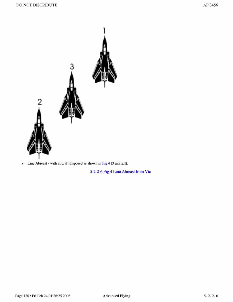
c. Line Abreast - with aircraft disposed as shown in Fig 4 (3 aircraft).
5-2-2-6 Fig 4 Line Abreast from Vic
c. Line Abreast - with aircraft disposed as shown in Fig 4 (3 aircraft).
5-2-2-6 Fig 4 Line Abreast from Vic
DO NOT DISTRIBUTE AP 3456
Page 120 : Fri Feb 24 01:26:25 2006 Advanced Flying 5- 2- 2- 6

d. Line Astern - with aircraft disposed as shown in Fig 5 (3 aircraft).
5-2-2-6 Fig 5 Line Astern from Vic
d. Line Astern - with aircraft disposed as shown in Fig 5 (3 aircraft).
5-2-2-6 Fig 5 Line Astern from Vic
DO NOT DISTRIBUTE AP 3456
Page 121 : Fri Feb 24 01:26:26 2006 Advanced Flying 5- 2- 2- 6

e. Box - with four aircraft disposed as shown in Fig 6.
For cloud penetration it is recommended that the maximum size of a close formation should be three aircraft. A three will invariablyfly as a Vic, and a pair as an echelon, as it is essential for the formating pilots to be able to see any hand signals made by the leader(see Annex). As the visibility in cloud can be very poor, formation leaders may brief that hand signals will not be used in cloud
DO NOT DISTRIBUTE AP 3456
Page 122 : Fri Feb 24 01:26:26 2006 Advanced Flying 5- 2- 2- 6

except in an emergency.
5-2-2-6 Fig 6 Box Formation
8. Four-ship formations manoeuvred from Box are shown in Figs 7, 8, 9 and 10. The flying of larger formations will be covered inmore detail in paras 58-65.
CLOSE FORMATION FLYING TECHNIQUE
Relative Speeds
9. The driver of a car subconsciously judges the speed of his vehicle in relation to others against a background of fixed objects -trees, houses, telegraph poles, etc - which border the road. Such a background does not exist in the air and the only way in whichrelative distances can be judged is by mentally comparing the actual and apparent size of an aircraft.
5-2-2-6 Fig 7 Echelon Starboard from Box
DO NOT DISTRIBUTE AP 3456
Page 123 : Fri Feb 24 01:26:26 2006 Advanced Flying 5- 2- 2- 6
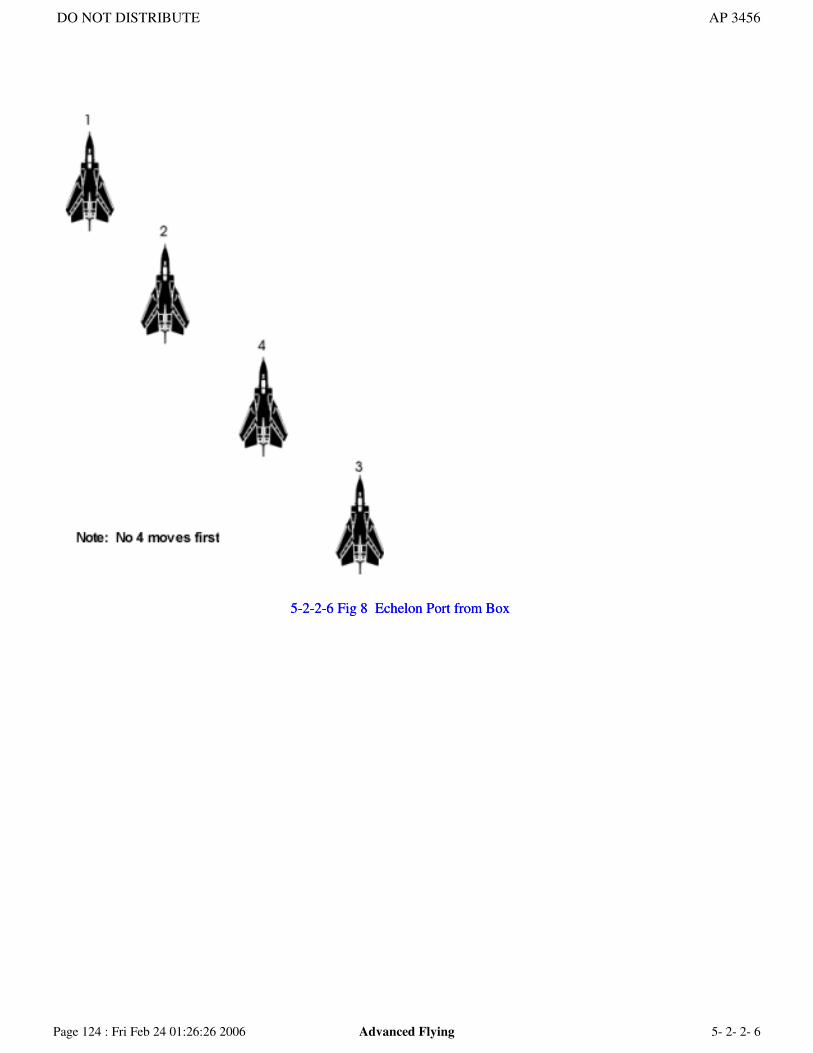
5-2-2-6 Fig 8 Echelon Port from Box5-2-2-6 Fig 8 Echelon Port from Box
DO NOT DISTRIBUTE AP 3456
Page 124 : Fri Feb 24 01:26:26 2006 Advanced Flying 5- 2- 2- 6

5-2-6 Fig 9 Line Abreast from Box
10. The difference in size of an aircraft viewed from six km range and from three km range is very small, but the difference in size of
5-2-6 Fig 9 Line Abreast from Box
10. The difference in size of an aircraft viewed from six km range and from three km range is very small, but the difference in size of
DO NOT DISTRIBUTE AP 3456
Page 125 : Fri Feb 24 01:26:26 2006 Advanced Flying 5- 2- 2- 6
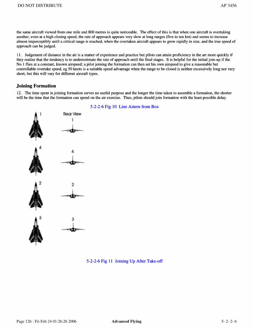
the same aircraft viewed from one mile and 800 metres is quite noticeable. The effect of this is that when one aircraft is overtakinganother, even at a high closing speed, the rate of approach appears very slow at long ranges (five to ten km) and seems to increasealmost imperceptibly until a critical range is reached, when the overtaken aircraft appears to grow rapidly in size, and the true speed ofapproach can be judged.
11. Judgement of distance in the air is a matter of experience and practice but pilots can attain proficiency in the art more quickly ifthey realize that the tendency is to underestimate the rate of approach until the final stages. It is helpful for the initial join-up if theNo 1 flies at a constant, known airspeed; a pilot joining the formation can then set his own airspeed to give a reasonable butcontrollable overtake speed, eg 50 knots is a suitable speed advantage when the range to be closed is neither excessively long nor veryshort, but this will vary for different aircraft types.
Joining Formation
12. The time spent in joining formation serves no useful purpose and the longer the time taken to assemble a formation, the shorterwill be the time that the formation can spend on the air exercise. Thus, pilots should join formation with the least possible delay.
5-2-2-6 Fig 10 Line Astern from Box
5-2-2-6 Fig 11 Joining Up After Take-off
DO NOT DISTRIBUTE AP 3456
Page 126 : Fri Feb 24 01:26:26 2006 Advanced Flying 5- 2- 2- 6
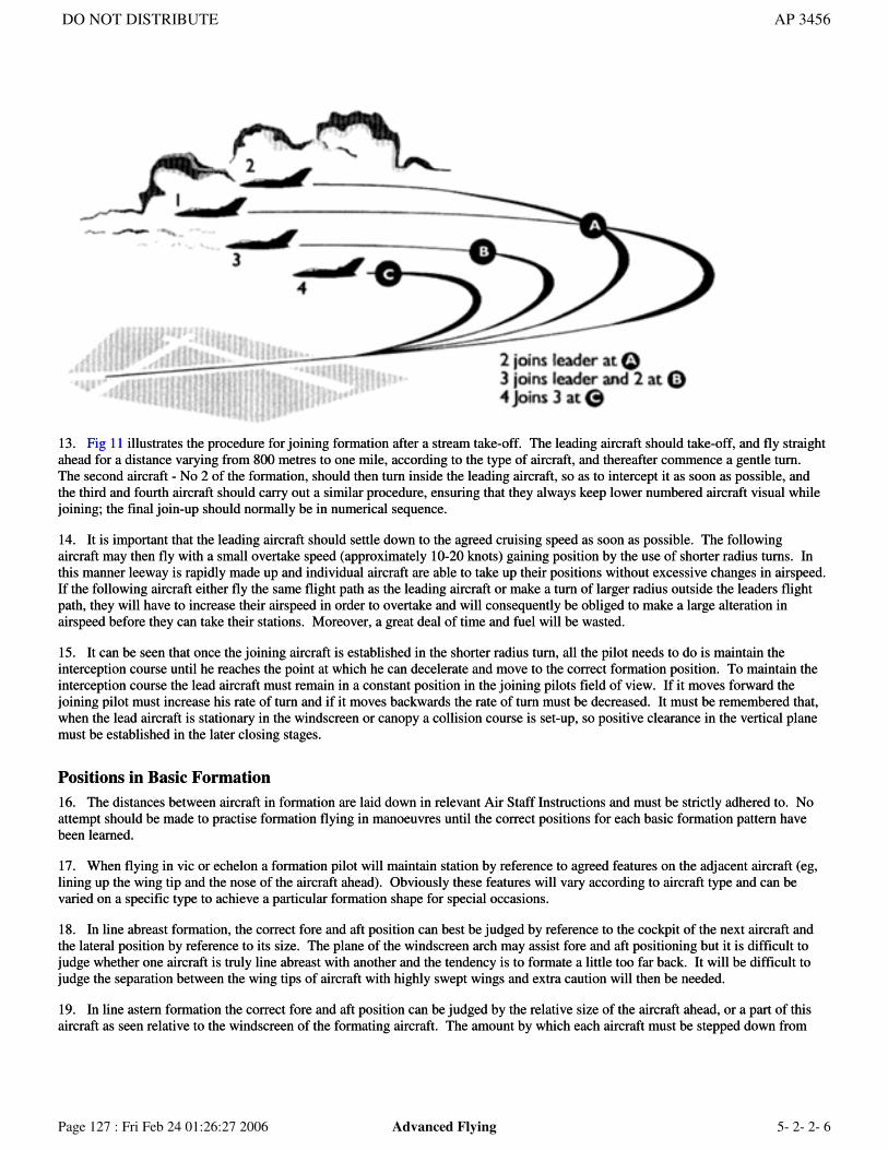
13. Fig 11 illustrates the procedure for joining formation after a stream take-off. The leading aircraft should take-off, and fly straightahead for a distance varying from 800 metres to one mile, according to the type of aircraft, and thereafter commence a gentle turn.The second aircraft - No 2 of the formation, should then turn inside the leading aircraft, so as to intercept it as soon as possible, andthe third and fourth aircraft should carry out a similar procedure, ensuring that they always keep lower numbered aircraft visual whilejoining; the final join-up should normally be in numerical sequence.
14. It is important that the leading aircraft should settle down to the agreed cruising speed as soon as possible. The followingaircraft may then fly with a small overtake speed (approximately 10-20 knots) gaining position by the use of shorter radius turns. Inthis manner leeway is rapidly made up and individual aircraft are able to take up their positions without excessive changes in airspeed.If the following aircraft either fly the same flight path as the leading aircraft or make a turn of larger radius outside the leaders flightpath, they will have to increase their airspeed in order to overtake and will consequently be obliged to make a large alteration inairspeed before they can take their stations. Moreover, a great deal of time and fuel will be wasted.
15. It can be seen that once the joining aircraft is established in the shorter radius turn, all the pilot needs to do is maintain theinterception course until he reaches the point at which he can decelerate and move to the correct formation position. To maintain theinterception course the lead aircraft must remain in a constant position in the joining pilots field of view. If it moves forward thejoining pilot must increase his rate of turn and if it moves backwards the rate of turn must be decreased. It must be remembered that,when the lead aircraft is stationary in the windscreen or canopy a collision course is set-up, so positive clearance in the vertical planemust be established in the later closing stages.
Positions in Basic Formation
16. The distances between aircraft in formation are laid down in relevant Air Staff Instructions and must be strictly adhered to. Noattempt should be made to practise formation flying in manoeuvres until the correct positions for each basic formation pattern havebeen learned.
17. When flying in vic or echelon a formation pilot will maintain station by reference to agreed features on the adjacent aircraft (eg,lining up the wing tip and the nose of the aircraft ahead). Obviously these features will vary according to aircraft type and can bevaried on a specific type to achieve a particular formation shape for special occasions.
18. In line abreast formation, the correct fore and aft position can best be judged by reference to the cockpit of the next aircraft andthe lateral position by reference to its size. The plane of the windscreen arch may assist fore and aft positioning but it is difficult tojudge whether one aircraft is truly line abreast with another and the tendency is to formate a little too far back. It will be difficult tojudge the separation between the wing tips of aircraft with highly swept wings and extra caution will then be needed.
19. In line astern formation the correct fore and aft position can be judged by the relative size of the aircraft ahead, or a part of thisaircraft as seen relative to the windscreen of the formating aircraft. The amount by which each aircraft must be stepped down from
DO NOT DISTRIBUTE AP 3456
Page 127 : Fri Feb 24 01:26:27 2006 Advanced Flying 5- 2- 2- 6

the preceding aircraft varies according to the slip-stream from each type of aircraft, but generally should be as small as possible. Toolarge a vertical interval between aircraft results in the last member of the formation flying very much lower than the leader and thismay cause some difficulty in turns.
Keeping Station - Straight and Level Flight
20. All pilots should aim to achieve smoothness in their formation flying. This is particularly important when more than a singleaircraft is formating in echelon, line astern or line abreast, since the movement of one aircraft in relation to another is accentuatedtowards the outside of the formation. If the second aircraft in the formation is flown roughly, the pilot of the aircraft on the outside ofthe formation will have an extremely difficult task. This may be simplified, however, by keeping station longitudinally and verticallyon the lead aircraft instead of the next aircraft, thereby reducing the ‘whip’ effect.
21. To keep his position constant in relation to the leader of the formation, the formating pilot may be required to adjust his positionlongitudinally, laterally and/or vertically. A keen sense of anticipation must be developed so that correcting movements are kept to aminimum.
22. Longitudinal Station Keeping. Changes of position in the longitudinal direction are made using the throttle to make small speedchanges and this in turn may necessitate a small movement of the elevators to maintain position vertically; thus co-ordinatedmovements of the two controls are made throughout. To maintain a constant position longitudinally the throttle should be moved inthe appropriate direction immediately any change is noticed or anticipated. This movement should be smooth and no more than isnecessary to correct errors, large throttle movements will usually result in over-correction, making station-keeping difficult andincreasing fuel consumption; the latter may be critical on long sorties. It must be remembered that a clean aircraft usually acceleratesquickly and decelerates slowly because of its low drag and due allowance must be made for this. Jet engine aircraft may have pooracceleration, especially at low air speeds, and also decelerate slowly, both effects must be anticipated.
23. Lateral Station Keeping. Changes in lateral position are made by gentle movements of aileron, in some aircraft, co-ordinated useof rudder. Small angles of bank should be used to correct lateral spacing and, when approaching the correct position, opposite bankwill be required to return to the leader’s heading and so maintain the new position.
24. Vertical Station Keeping. Position in the vertical plane is controlled by the elevators. At some stages of flight, notably on anapproach, in aircraft with highly-swept wings, even small changes of angle of attack caused by elevator movement will require somethrottle movement to maintain longitudinal positioning. Coordination of elevator and throttle is important.
Keeping Station - Turns
25. Fig 12 shows how, during a turn in vic formation, the outside aircraft describes a turn of larger radius, and the inside aircraft aturn of smaller radius, than the leading aircraft. To maintain the correct position relative to the leader it is necessary therefore for theoutside aircraft to increase speed, whilst the inside aircraft must reduce speed. When a turn is initiated, the formating pilot shouldendeavour to anticipate an alteration in power. The greater the lateral distance between the leader and the formating aircraft, thegreater will be necessary speed adjustments. It is this factor which limits the manoeuvrability of large formations.
5-2-2-6 Fig 12 Comparison of Turning Paths in Horizontal Formations
DO NOT DISTRIBUTE AP 3456
Page 128 : Fri Feb 24 01:26:27 2006 Advanced Flying 5- 2- 2- 6

26. Fig 13, illustrating three aircraft carrying out a turn in the line astern position, shows that each aircraft flies a longer distance thanthe aircraft above it. The necessity for stepping down no more than the essential amount, especially when large numbers of aircraftare flying in this type of formation, can be plainly observed.
5-2-2-6 Fig 13 Comparison of Turning Paths in Vertical Formations
27. The sensations experienced during turns in vic formation, especially on the outside of steep turns, may at first be disconcerting,but it will be quickly learned that the outside aircraft is in no danger of slipping down onto the leading aircraft. The controlmovements required for keeping station, as described in Paras 20 to 24, apply during any manoeuvre - even during inverted flight.
28. It is a pre-requisite of good formation flying that the formating pilots should trust their No 1 and concentrate on accurate station
DO NOT DISTRIBUTE AP 3456
Page 129 : Fri Feb 24 01:26:27 2006 Advanced Flying 5- 2- 2- 6
keeping without giving too much attention to any particular manoeuvre which may be carried out. Experience enables pilots to fly information and at the same time to realize exactly what manoeuvres are being executed; until this experience is gained, any temporarydisorientation which they may experience should be ignored. The importance of thorough pre-flight briefing cannot beover-emphasized.
CHANGING CLOSE FORMATION
General
29. Rapid and efficient changes of formation may be required operationally (eg for the run-in and break) or for the purpose ofdisplay flying. They are an essential part of formation flying and all pilots should aim at the highest standards of promptness and skillin their operation.
Briefing of Close Formation Changes
30. To ensure safe operations, pilots must know precisely which positions they are to occupy in a formation. It follows thereforethat intended formation positions must be specifically briefed before flight. The guiding principle to be followed in formationchanges is that the minimum number of aircraft should move to effect the change. It is not intended to list all possible combinationsof formation changes but Paras 34-41 indicate the general methods employed.
Use of R/T and Hand Signals
31. Formations are allocated code names eg ‘Tankard’. This enables the No 1 to pass messages and receive them from any particularsub-unit or individual in the formation. He is termed ‘Tankard 1’. A Section is allocated a colour; “RED”, “YELLOW” or“BLUE” with callsign ‘Tankard Blue Section’ for instance. In each section aircraft are numbered one, two, three and so on. Within‘Blue Section’ the aircraft callsigns are Tankard Blue One, Two or Three.
32. Radio calls and hand signals must be standard, unmistakable and clear of ambiguity:
a. R/T. A call is made as follows: “Tankard BLUE - ECHELON PORT- ECHELON PORT - GO”. The word “GO” is theexecutive order. After it is given, those aircraft required to move position must acknowledge with their call-sign. A slight pauseis observed before starting to carry out the order; this is important where the operation of flaps, airbrakes or undercarriage iscalled for in close formation.
b. Hand Signals. Pilots must be prepared to operate in conditions of radio silence and should become accustomed to workingwith a minimum of calls; in close formation visual hand signals usually suffice. A table of the standard formation hand signalsused in the Royal Air Force is at the Annex to this chapter.
Look-out During Formation Changing
33. Changes of formation are made on the commands of the formation No 1, as detailed in the following paragraphs. During allchanges of formation it is vitally important that each pilot who is changing position should keep the rest of the aircraft in theformation in view. Where this is not possible eg large formations, pilots should not move formation position until aircraft outsidetheir field of view have called clear.
Section Formation Changing
34. Vic to Echelon Starboard. The command is “BLUE SECTION - ECHELON STARBOARD - ECHELON STARBOARD -
GO”. After acknowledging, No 3 drops back and down, moves across and then forward and up into position.
35. Vic to Echelon Port. The command is “BLUE SECTION ECHELON PORT - ECHELON PORT GO”. Afteracknowledging, No 2 moves back and down, then across, forward and up into position. Note that No 3 holds his position next to No1.
36. Vic to Line Abreast. The command is “BLUE SECTION - LINE ABREAST - LINE ABREAST GO”. After acknowledging,No’s 2 and 3 move forward into position and call in.
DO NOT DISTRIBUTE AP 3456
Page 130 : Fri Feb 24 01:26:27 2006 Advanced Flying 5- 2- 2- 6
37. Vic to Line Astern. The command is “BLUE SECTION - LINE ASTERN - LINE ASTERN - GO”. After acknowledgementby No’s 2 and 3, No 3 moves back and down and calls clear. When No 2 hears that No 3 is clear he moves back, down and acrossinto position. When No 3 sees that No 2 is in position he moves across into position and calls in. No 3 is responsible for avoidingNo 2 throughout the formation change.
38. Box to Echelon Starboard. The command is “BLUE SECTION - ECHELON STARBOARD - ECHELON STARBOARD -
GO”. After acknowledgement by Nos 3 and 4, No 4 moves back and across into position and calls clear. When No 3 hears that it isclear he drops back and down until he can see the other three aircraft, he then moves across and into position on the outside of thesection.
39. Box to Echelon Port. The command is “BLUE SECTION - ECHELON PORT - ECHELON PORT - GO”. Afteracknowledgement by Nos 2 and 4, No 4 moves back and across into position and calls clear. When No 2 hears that it is clear, hemoves back and down until he can see the other three aircraft, and then moves across on the outside of the echelon.
40. Box to Line Abreast. The command is “BLUE SECTION - LINE ABREAST - LINE ABREAST - GO”. Afteracknowledgement by No’s 2, 3 and 4. No’s 2 and 3 move forward on No 1. When No 4 sees they are in position he moves acrossand forward into either the right hand or left hand position as required or briefed.
41. Box to Line Astern. The command is “BLUE SECTION - LINE ASTERN - LINE ASTERN - GO”. After No’s 2 and 3 haveacknowledged, No 3 moves back and down and calls clear. When No 2 hears that No 3 is clear, he moves back and down and acrossinto position behind No 4. When No 3 sees that No 2 is in position he moves across into position behind No 2 and calls clear. No 3is responsible for avoiding No 2 throughout the formation change.
FORMATION TAKE-OFF
General
42. It is usual for aircraft to take-off in pairs formation but in some circumstances a Vic take-off may be appropriate. At flyingtraining schools, for instance, Vic take-offs are preferred since they provide the opportunity to train two students at a time. For anytype of aircraft the choice between Vic and Pairs will also depend upon consideration of wing span, main-wheel track, runway widthand crosswind component.
Taxiing
43. Whilst a formation of aircraft is taxiing, there is a danger of airframe and engine damage (FOD) to the following aircraft causedby stones and other debris thrown up by the jet efflux or slipstream of the preceding one. Therefore, a safe spacing of normally atleast 150 metres must be maintained when taxiing. A safe spacing for taxiing will normally be laid down by the operating authority.
Line-up and Take-off
44. For a Vic formation take-off, the No 1 will line-up on the centre line and the No’s 2 and 3 will position themselves on theirrespective halves of the runway in the correct fore and aft station and with safe lateral spacing between wing tips. Prior to a pairstake-off, both aircraft may take the middle of their respective halves of the runway with the No 2 positioning himself correctlylongitudinally. The No 1 will signal to open up to a briefed power setting against the brakes and on receiving the ‘ready’ signal fromthe No’s 2 and 3 (when applicable) will order a ‘release brakes’ opening up smoothly to the desired take-off power. Wing-men mustconcentrate on staying with the No 1 whilst making their own take-offs, but the original runway spacing should be held until safelyairborne to reduce the risk of collision should directional control problems occur.
Interval Between Pairs
45. The time interval between pairs (or singletons) during a stream take-off varies with aircraft type and prevailing conditions -normally 10-15 seconds will suffice. On aircraft types where runway length may not be important, eg STOVL aircraft, the intervalbetween pairs (or singletons) can be achieved by spacing the pairs on the runway and rolling together. If the join-up cannot be madebelow cloud, the interval should be increased (typically to 30 seconds) to allow for either a snake or radar controlled climb.
Slip-stream During Take-off
DO NOT DISTRIBUTE AP 3456
Page 131 : Fri Feb 24 01:26:27 2006 Advanced Flying 5- 2- 2- 6

46. To minimize slip-stream effects, pairs may be briefed to pull high or hold low immediately after take-off - the low pairs aimingto unstick beyond the point where the preceding one became airborne. This technique, however, is no longer recommended for highperformance aircraft when it is better, where necessary, to increase the time interval and use turns to effect a rapid join-up aftertake-off. The effects of aircraft wakes are discussed in Pt 2, Sect 2, Chap 2, Para 22.
FORMATION LANDING
General
47. Formation landings are usually carried out in pairs from a circuit or radar approach, with the No 1 landing on the down-wind sideof the runway.
48. Formation landings should be attempted only by pilots who have attained a high standard of formation flying. Absoluteconfidence in the No 1 is essential.
Technique and Procedure
49. After joining the circuit in the usual manner, the No 1 turns down-wind and reduces to circuit speed as smoothly as possible. Atthe correct speed the No 1 gives the signal to lower the landing gear and flaps; formating pilots must anticipate any changes of trimand complete their vital actions. It is important for pilots to resist any temptation to over-control at this stage.
50. The turn onto the final approach should be as gentle as possible so that the formating pilots can keep station comfortably. If afurther change in aircraft configuration is required for landing, this should be ordered by the No 1 as early as possible to enable theformation to settle down. At this stage pilots should appreciate that their aircraft response is more sluggish than at cruising speed. Itis vital that wing-men counter any tendency to drop low or fall back on the No 1 on late finals. Flying low might lead to thewing-man landing in the under-shoot and dropping back might place him in the No 1’s slip-stream or jet wash. Additionally, aformating pilot should beware of over-shooting the No 1 since throttling back too much at this stage might place the engine in the lowresponse region, of rpm.
51. The wing-man’s aim is to achieve his own individual landing whilst keeping station on the No 1. In this way, the angle ofapproach and airspeed can be controlled by the No 1 whilst the wing-man is responsible for lining-up and landing on his half of therunway. It follows that the wing-man must split his attention between the No 1 and the runway. Initially all that is required is aglance ahead to assess line-up and drift but, from approximately 500 feet agl, or Decision Height if the formation has been in cloud,progressively higher priority must be given to the runway. On crossing the threshold, the wing-man should make a normal landingpromptly whilst the No 1 will delay closing his throttle for two to three seconds to assist the wing-man in initiating nose-to-tailseparation.
52. Once formating aircraft are firmly on the ground they should commence braking without delay. The No 1 should delay his ownbraking slightly until he sees the formating aircraft are safely down and decelerating. The aim is to establish fore and aft aircraftseparation as soon as possible in case of directional control problems. Individuals must maintain their lateral position on the runwayuntil cleared to move across by those behind them. The temptation to relax at this stage should be strongly resisted; a formationlanding is not complete until all the aircraft are clear of the runway.
THE BREAK AND STREAM LANDING
General
53. If close formation landings are not required or are precluded by the prevailing conditions (eg crosswind), the break and streamlanding procedure is usually used.
54. If the weather is suitable for a visual circuit, the leader of the section should approach on the heading of the runway in use at thebriefed height, slightly on the dead side, with his formation in echelon starboard (left hand traffic). On crossing the runway thresholdthe leader should bank and pull away firmly to the left, followed in order by the rest of the section at the briefed interval. Each pilotshould throttle well back, open the airbrakes and lower partial flap (depending, on the aircraft type) and maintain a continuous turn,aiming to roll out in line with the aircraft ahead and at the same height, whether the break was level or climbing. A useful method ofjudging relative height is by placing the No 1 on the horizon. Individual aircraft should aim to achieve a position 1000 metres asternof each other from which point essentially individual landings are carried out. The pre-landing checks should be completed at a
DO NOT DISTRIBUTE AP 3456
Page 132 : Fri Feb 24 01:26:27 2006 Advanced Flying 5- 2- 2- 6

suitable point. Caution should be exercised on finals to avoid going too low or using excessive power; the hazard of wake turbulenceshould be emphasized during the briefing.
55. The No 1 should aim to land on the runway centreline and then move to the exit side of the runway when safely under control.Subsequent aircraft should also touch down on the centreline and move to the exit side of the runway after it is obvious that they canstop within the distance between them and the aircraft ahead. A minimum separation distance will normally be laid down by theoperating authority. It is important when large formations are stream landing that after checking the satisfactory operation of thebrakes after touch down, all aircraft keep rolling to the end of the runway. Unnecessarily harsh braking in the landing run should beavoided, or bunching will occur, and the distance-to-go markers should be used to aid judgement of progressive braking.
56. A landing formation must know of any unusual conditions of runway or crosswinds, and the No 1 should always ascertain thesefrom Air Traffic Control who will normally pass this type of information as a matter of routine. Controllers should realize that thereis much that can be done to help formations. If necessary, the No 1 should order his formation to increase their spacing having takeninto account of any unusual circumstances.
57. It will be noted that a break from the standard echelon positions described earlier will lead to landings out of numericalsequence. Whilst this is accepted at RAF airfields, it is not at many other NATO airfields. Operational units may overcome thisdifficulty by forming non-standard sequentially numbered echelons from tactical formation, as described later, or the No 1 may ordera sequential renumbering of the echelon during the run-in. The standard rule is that aircraft will break in numerical order so, if it isintended to break out of sequence, the procedure must be carefully pre-briefed in order to avoid any confusion.
LARGE FORMATIONS
General
58. When formations of more than four aircraft are to be flown, it is essential that all members of the formation are carefully selectedand are given sufficient practice in the position in which they are to fly. Practice should be given in separate sections before the mainformation is formed.
Formation Positions
59. Normally, large formations will be formed of several smaller sections and, if the formation is to be a loose one, these sectionsshould remain intact with the section leaders positioning to give the required overall shape. If, however, the formation is to be fullyintegrated, it is advised that the second and subsequent line wing-men formate in line astern on the wing-man ahead. This ensuresthat the pilot has precise formation references and, within his peripheral vision he should be able to see the aircraft on the other sideof him. The formation No 1 must brief at what stage of the formation join up, formation wing-men are to transfer their attention tothe aircraft ahead; it is suggested that this is when the section leader calls that he is in position.
Numbering of Large Formations
60. If, as stated above, a large formation (eg, a ‘Diamond Nine’) is to be formed from separate sections, an unambiguous numberingsystem should be adopted when the join-up is complete. This will require the formation to re-number in the air on the command ofthe formation No 1. The numbering shown in Fig 14 and 15 follows the general rule that odd numbers are on the left of theformation, and even numbers are on the right.
Changes of Formation
61. Changes of formation are made in accordance with the principles described earlier, whatever the number of aircraft in theformation. In order to avoid the danger of collision, however, certain additional rules must be observed for larger formations.
62. Changes of close formation within a section will always be called by the section No 1 and executed on the command “GO”. Inlarger formations, the overall No 1 will often direct the movement of sections with non-executive calls eg “Tankard Formation, formboxes, close trail”. Alternatively, the formation No 1 may wish to order individual section movements when the needs of flight safetyso dictate, eg, “Red section drop back and call clear - GO”.
63. Ordering formation changes in large formations can easily lead to confusion. Whatever the occasion and no matter how simplethe formation changes might appear, there is no substitute for careful planning particularly of the joining and splitting-up stages of the
DO NOT DISTRIBUTE AP 3456
Page 133 : Fri Feb 24 01:26:27 2006 Advanced Flying 5- 2- 2- 6
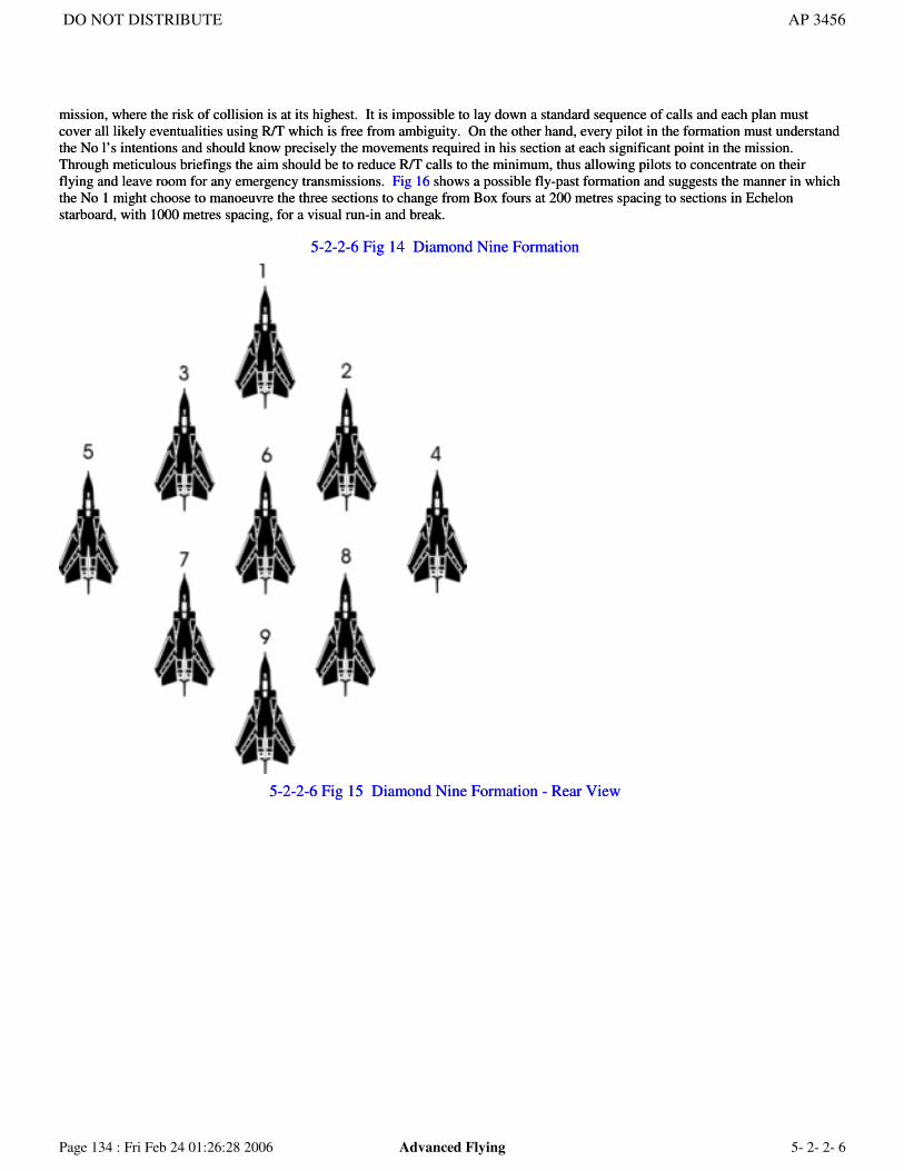
mission, where the risk of collision is at its highest. It is impossible to lay down a standard sequence of calls and each plan mustcover all likely eventualities using R/T which is free from ambiguity. On the other hand, every pilot in the formation must understandthe No l’s intentions and should know precisely the movements required in his section at each significant point in the mission.Through meticulous briefings the aim should be to reduce R/T calls to the minimum, thus allowing pilots to concentrate on theirflying and leave room for any emergency transmissions. Fig 16 shows a possible fly-past formation and suggests the manner in whichthe No 1 might choose to manoeuvre the three sections to change from Box fours at 200 metres spacing to sections in Echelonstarboard, with 1000 metres spacing, for a visual run-in and break.
5-2-2-6 Fig 14 Diamond Nine Formation
5-2-2-6 Fig 15 Diamond Nine Formation - Rear View
DO NOT DISTRIBUTE AP 3456
Page 134 : Fri Feb 24 01:26:28 2006 Advanced Flying 5- 2- 2- 6

64. It can be seen from the foregoing paragraphs that all formation changes must be carried out with care and, of course, the correctmethods taught and practised from the earliest days of a pilot’s training. However, unfamiliar situations lend themselves readily tomisunderstanding and in these cases No 1 must not assume that individuals know the formation manoeuvring required, and shouldinclude them in the pre-flight briefing. The following are two common areas of possible confusion:
a. Training Aircraft. Training aircraft most often operate in sections of three using Vic, Echelon and Line Astern. Pilots areaccustomed to the individual positions. Adding an extra aircraft to form a Box 4 will require careful briefing since it cannot beassumed that the same pilots are familiar with the different sequence of formation changes involved.
5-2-2-6 Fig 16 Large Formation Manoeuvring
DO NOT DISTRIBUTE AP 3456
Page 135 : Fri Feb 24 01:26:28 2006 Advanced Flying 5- 2- 2- 6

b. Operational Fast Jet Aircraft. Operational fast jets usually fly in tactical formations of two or four aircraft. Pilots areaccustomed to completing their missions with a visual run-in and break from a tactical formation such as Battle or Arrow. Theymay not expect to be called into a close echelon and if the No 1 intends this, he should brief accordingly.
Landing a Large Formation
65. It is important that each section of a large formation should spend a minimum of time in the circuit to reduce congestion andminimize delays for following aircraft. Minimum circuit time is achieved by employing the stream-landing technique.
TACTICAL FORMATIONS
Introduction
66. Tactical formations are planned and flown to achieve as good a defensive posture as possible. Such a posture will depend uponhow many aircraft are involved and the profile of the sortie. A 2-aircraft formation in line abreast may achieve good rearwardslookout but is relatively unwieldy in turns. The same 2-aircraft formation in long line astern is easily manoeuvred but cross cover isseverely limited. Compromise formations are selected, therefore, to give optimum defensive cover and many are developed as themost appropriate for individual squadrons and for particular aircraft types. It is not possible to cover all variations so the tacticalformations described in this chapter are the three more simple manoeuvres generally taught in the relevant flying training schools and
DO NOT DISTRIBUTE AP 3456
Page 136 : Fri Feb 24 01:26:28 2006 Advanced Flying 5- 2- 2- 6

from which advanced tactical formation profiles are developed. They are:
a. Fighting Wing.
b. Defensive Battle.
c. Arrow.
Considerations
67. Range Estimation. Range estimation improves with experience. Even so, exact distances tend to be a matter of opinion andcannot be assessed with any degree of accuracy. The correct distances between aircraft will more readily be described as ‘a bit tooclose’, or ‘rather wide’ or the like and correct spacing will, with practice, become second nature. That said, since this terminologycannot be used in a written description, distances are described more precisely in this chapter.
Airmanship
68. Lookout. The purpose of a tactical formation is to take advantage of good lookout. The No 1 is responsible for formationsecurity but relies upon his wingmen to give warning of other aircraft be they hostile or friendly. Reports to the leader must be quickand accurate giving all the essential information in a dispassionate and unemotional manner.
69. Slipstream. Aircraft in formation should take care to avoid the slipstream of other formation aircraft. Apart from dangerouscontrol difficulties, flying into turbulent air might lead to unacceptable rises in turbine gas temperature (TGT).
70. Terrain and Collision Avoidance. Each pilot in a tactical formation is responsible for maintaining a safe distance from otheraircraft and from the terrain. It is particularly important to be aware of the briefed MSD when at low level and to break off, ifnecessary, for a safe rejoin.
71. Sighting Reports. A thorough lookout for threat aircraft must be maintained. All aircraft, whether believed to be hostile or notmust be reported when on a tactical communications frequency. In training, the briefing will usually require only threats or collisionrisks to be reported on an ATC frequency. Sighting reports should be given as follows:
a. Callsign of reporting aircraft.
b. Left/Right and clock code (relative to leader).
c. High, low or level.
d. Range.
e. Type and number of aircraft.
f. What sighted aircraft are doing.
Fighting Wing Formation
72. General. Fighting Wing (Fig 17), in which the No 2 occupies a cone behind the leader of about 60° apex and 200 - 300 m depth,offers the leader good cross cover and greater maneuverability than close formation. Fighting Wing is normally flown as two aircraft.With four aircraft, pairs trail would normally be flown. The rear pair should maintain the briefed trail separation which will be in theorder of 1500 - 2000 metres depending upon conditions.
5-2-2-6 Fig 17 Fighting Wing Formation
DO NOT DISTRIBUTE AP 3456
Page 137 : Fri Feb 24 01:26:28 2006 Advanced Flying 5- 2- 2- 6

73. Manoeuvres. Manoeuvring to remain on station during turns is relatively easy and all-round lookout should be maintained byeach pilot. Except when otherwise briefed, the No 2 maintains the altitude of his leader during turns thus limiting the verticalenvelope of the formation. This makes transit at low level particularly effective. However, during low level manoeuvres, the No 2must not descend below his leader.
Defensive Battle Formation
74. Description. Despite the relative effectiveness of Fighting Wing formation, Defensive Battle is the basic tactical formation usedin the RAF. It is the best compromise between effective lookout, mutual support, manoeuvrability and reduction in vulnerability.The distance apart depends upon visibility and the expected weapon threat and, once the optimum has been decided, convergence anddivergence must be countered continuously. The configuration for two aircraft is shown in Fig 18.
5-2-2-6 Fig 18 Defensive Battle Line Abreast
DO NOT DISTRIBUTE AP 3456
Page 138 : Fri Feb 24 01:26:28 2006 Advanced Flying 5- 2- 2- 6

75. Lookout and Search Areas. Areas of responsibility for visual search and the lookout sectors are shown in Fig 19. Aircrewshould spend about three quarters of their time searching their primary (blank) field and the rest searching the remainder of the sky(shaded). The entire sky, vertically as well as level, must be covered.
5-2-2-6 Fig 19 Defensive Battle Formation Lookout Sectors
76. Pre-planned Route Turns. On a pre-planned route, turns will normally not be called. The leader will fly the briefed route andthe other aircraft or elements should anticipate the turns and remain on station. A two-aircraft turn through 25° to port is shown inFig 20.
5-2-2-6 Fig 20 Pre-planned Route Turn - Left 25 deg
DO NOT DISTRIBUTE AP 3456
Page 139 : Fri Feb 24 01:26:28 2006 Advanced Flying 5- 2- 2- 6
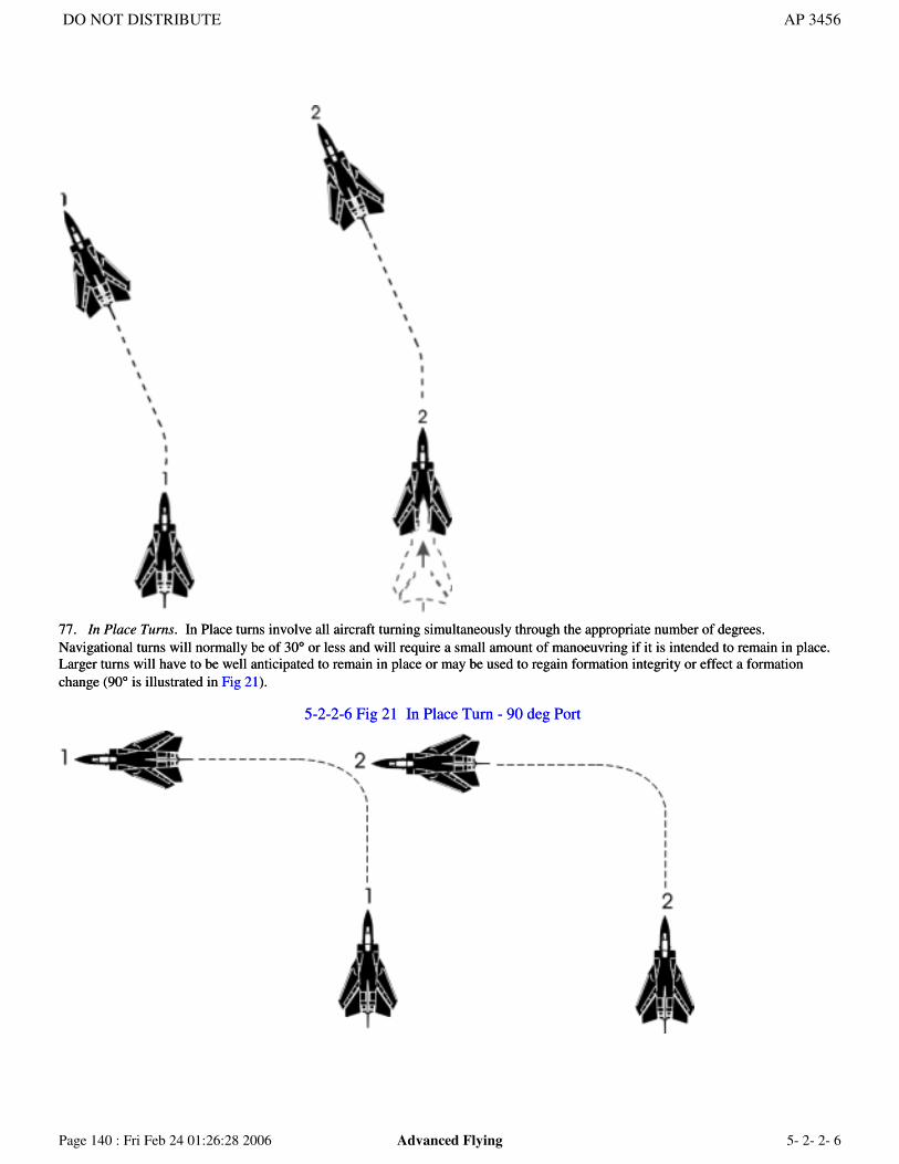
77. In Place Turns. In Place turns involve all aircraft turning simultaneously through the appropriate number of degrees.Navigational turns will normally be of 30° or less and will require a small amount of manoeuvring if it is intended to remain in place.Larger turns will have to be well anticipated to remain in place or may be used to regain formation integrity or effect a formationchange (90° is illustrated in Fig 21).
5-2-2-6 Fig 21 In Place Turn - 90 deg Port
DO NOT DISTRIBUTE AP 3456
Page 140 : Fri Feb 24 01:26:28 2006 Advanced Flying 5- 2- 2- 6
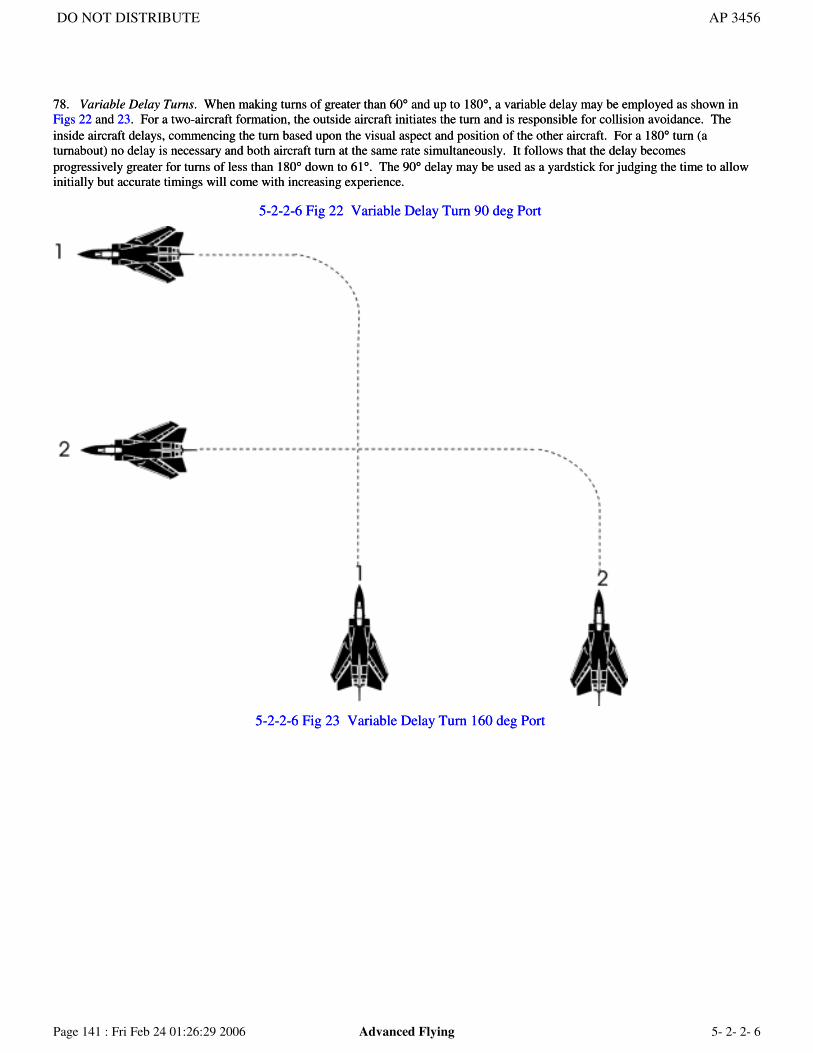
78. Variable Delay Turns. When making turns of greater than 60° and up to 180°, a variable delay may be employed as shown inFigs 22 and 23. For a two-aircraft formation, the outside aircraft initiates the turn and is responsible for collision avoidance. Theinside aircraft delays, commencing the turn based upon the visual aspect and position of the other aircraft. For a 180° turn (aturnabout) no delay is necessary and both aircraft turn at the same rate simultaneously. It follows that the delay becomesprogressively greater for turns of less than 180° down to 61°. The 90° delay may be used as a yardstick for judging the time to allowinitially but accurate timings will come with increasing experience.
5-2-2-6 Fig 22 Variable Delay Turn 90 deg Port
5-2-2-6 Fig 23 Variable Delay Turn 160 deg Port
DO NOT DISTRIBUTE AP 3456
Page 141 : Fri Feb 24 01:26:29 2006 Advanced Flying 5- 2- 2- 6

79. Assisted Turns. Assisted turns are generally used for turns between 30° and 60°. Assistance, in this context, is defined as anadditional compensatory turn to assist in final positioning. By applying the right amount of assistance, the length of flightpath is thesame for both aircraft and the manoeuvre ensures that both roll out close to the correct spacing. As a rule of thumb, the amount ofassistance needed is calculated by halving the difference between the required turn and 90° as shown in Table 1. A 60° starboardassisted turn is illustrated in Fig 24.
Table 1 - Calculating Assistance Required
Degrees of Turn Assistance Required
0 45°
30 30°
45 20°
60 15°
90 0°
5-2-2-6 Fig 24 60 deg Starboard Assisted Turn
DO NOT DISTRIBUTE AP 3456
Page 142 : Fri Feb 24 01:26:29 2006 Advanced Flying 5- 2- 2- 6

80. Four Aircraft Profiles. The four aircraft Battle formation is, essentially, two mirrored elements of fighting wing abreast in whichthe Nos 2 and 4 may assume a slightly longer trail. The profile and lookout areas of responsibility are illustrated in Fig 25. Onceagain, the illustrated primary (clear) areas should be scanned for about three quarters of the time and the shaded areas for the rest.The whole vertical extent of the sky must be included in the search. Turns of up to 30° may be carried out in place. Larger turns areconducted as for two aircraft Battle but the Nos 2 and 4 change sides for variable delay and assisted turns when their element leadersstart to turn, adjusting to resume the lookout regime shown in Fig 25 on roll-out.
5-2-2-6 Fig 25 Four Aircraft Defensive Battle and Lookout Areas
DO NOT DISTRIBUTE AP 3456
Page 143 : Fri Feb 24 01:26:29 2006 Advanced Flying 5- 2- 2- 6

Arrow Formation
81. General. Arrow formation is used for manoeuvring four aircraft in poor weather conditions or restricted airspace and isillustrated in Fig 26. Rearward lookout tends to be restricted but flexibility remains high. The No 2 should position himself at 75°
sweep and about 70 metres behind the leader (with small variations depending on aircraft type). The No 3 should be on the other sideof the leader, swept 75° and at double the rearward spacing of the No 2. (ie about 150 metres in this example). The No 4 spaceshimself outside the No 3 at 75° sweep and again about 75 metres behind.
82. Turns. Individual aircraft maintain longitudinal separation and do not normally change sides when turning and will manoeuvrein plane. This makes Arrow less manoevrable than Fighting Wing and the leader must plan turns within the available height to avoidunits changing sides.
5-2-2-6 Fig 26 Arrow Formation
DO NOT DISTRIBUTE AP 3456
Page 144 : Fri Feb 24 01:26:29 2006 Advanced Flying 5- 2- 2- 6

RecoveryRecovery
DO NOT DISTRIBUTE AP 3456
Page 145 : Fri Feb 24 01:26:29 2006 Advanced Flying 5- 2- 2- 6
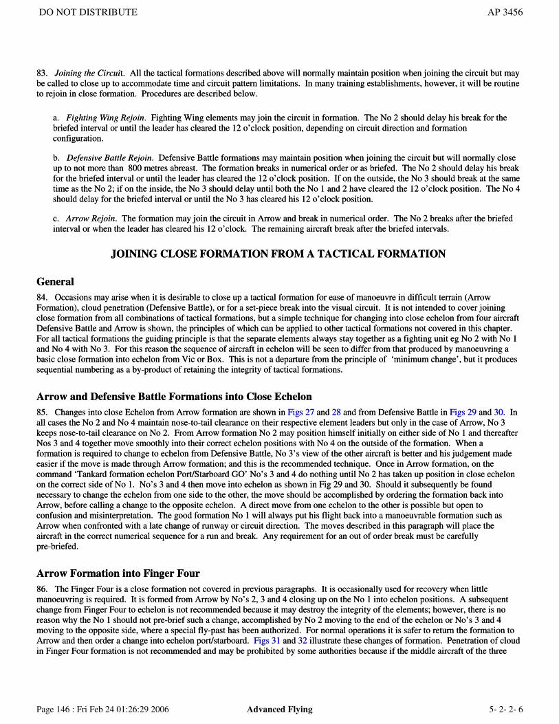
83. Joining the Circuit. All the tactical formations described above will normally maintain position when joining the circuit but maybe called to close up to accommodate time and circuit pattern limitations. In many training establishments, however, it will be routineto rejoin in close formation. Procedures are described below.
a. Fighting Wing Rejoin. Fighting Wing elements may join the circuit in formation. The No 2 should delay his break for thebriefed interval or until the leader has cleared the 12 o’clock position, depending on circuit direction and formationconfiguration.
b. Defensive Battle Rejoin. Defensive Battle formations may maintain position when joining the circuit but will normally closeup to not more than 800 metres abreast. The formation breaks in numerical order or as briefed. The No 2 should delay his breakfor the briefed interval or until the leader has cleared the 12 o’clock position. If on the outside, the No 3 should break at the sametime as the No 2; if on the inside, the No 3 should delay until both the No 1 and 2 have cleared the 12 o’clock position. The No 4should delay for the briefed interval or until the No 3 has cleared his 12 o’clock position.
c. Arrow Rejoin. The formation may join the circuit in Arrow and break in numerical order. The No 2 breaks after the briefedinterval or when the leader has cleared his 12 o’clock. The remaining aircraft break after the briefed intervals.
JOINING CLOSE FORMATION FROM A TACTICAL FORMATION
General
84. Occasions may arise when it is desirable to close up a tactical formation for ease of manoeuvre in difficult terrain (ArrowFormation), cloud penetration (Defensive Battle), or for a set-piece break into the visual circuit. It is not intended to cover joiningclose formation from all combinations of tactical formations, but a simple technique for changing into close echelon from four aircraftDefensive Battle and Arrow is shown, the principles of which can be applied to other tactical formations not covered in this chapter.For all tactical formations the guiding principle is that the separate elements always stay together as a fighting unit eg No 2 with No 1and No 4 with No 3. For this reason the sequence of aircraft in echelon will be seen to differ from that produced by manoeuvring abasic close formation into echelon from Vic or Box. This is not a departure from the principle of ‘minimum change’, but it producessequential numbering as a by-product of retaining the integrity of tactical formations.
Arrow and Defensive Battle Formations into Close Echelon
85. Changes into close Echelon from Arrow formation are shown in Figs 27 and 28 and from Defensive Battle in Figs 29 and 30. Inall cases the No 2 and No 4 maintain nose-to-tail clearance on their respective element leaders but only in the case of Arrow, No 3keeps nose-to-tail clearance on No 2. From Arrow formation No 2 may position himself initially on either side of No 1 and thereafterNos 3 and 4 together move smoothly into their correct echelon positions with No 4 on the outside of the formation. When aformation is required to change to echelon from Defensive Battle, No 3’s view of the other aircraft is better and his judgement madeeasier if the move is made through Arrow formation; and this is the recommended technique. Once in Arrow formation, on thecommand ‘Tankard formation echelon Port/Starboard GO’ No’s 3 and 4 do nothing until No 2 has taken up position in close echelonon the correct side of No 1. No’s 3 and 4 then move into echelon as shown in Fig 29 and 30. Should it subsequently be foundnecessary to change the echelon from one side to the other, the move should be accomplished by ordering the formation back intoArrow, before calling a change to the opposite echelon. A direct move from one echelon to the other is possible but open toconfusion and misinterpretation. The good formation No 1 will always put his flight back into a manoeuvrable formation such asArrow when confronted with a late change of runway or circuit direction. The moves described in this paragraph will place theaircraft in the correct numerical sequence for a run and break. Any requirement for an out of order break must be carefullypre-briefed.
Arrow Formation into Finger Four
86. The Finger Four is a close formation not covered in previous paragraphs. It is occasionally used for recovery when littlemanoeuvring is required. It is formed from Arrow by No’s 2, 3 and 4 closing up on the No 1 into echelon positions. A subsequentchange from Finger Four to echelon is not recommended because it may destroy the integrity of the elements; however, there is noreason why the No 1 should not pre-brief such a change, accomplished by No 2 moving to the end of the echelon or No’s 3 and 4moving to the opposite side, where a special fly-past has been authorized. For normal operations it is safer to return the formation toArrow and then order a change into echelon port/starboard. Figs 31 and 32 illustrate these changes of formation. Penetration of cloudin Finger Four formation is not recommended and may be prohibited by some authorities because if the middle aircraft of the three
DO NOT DISTRIBUTE AP 3456
Page 146 : Fri Feb 24 01:26:29 2006 Advanced Flying 5- 2- 2- 6
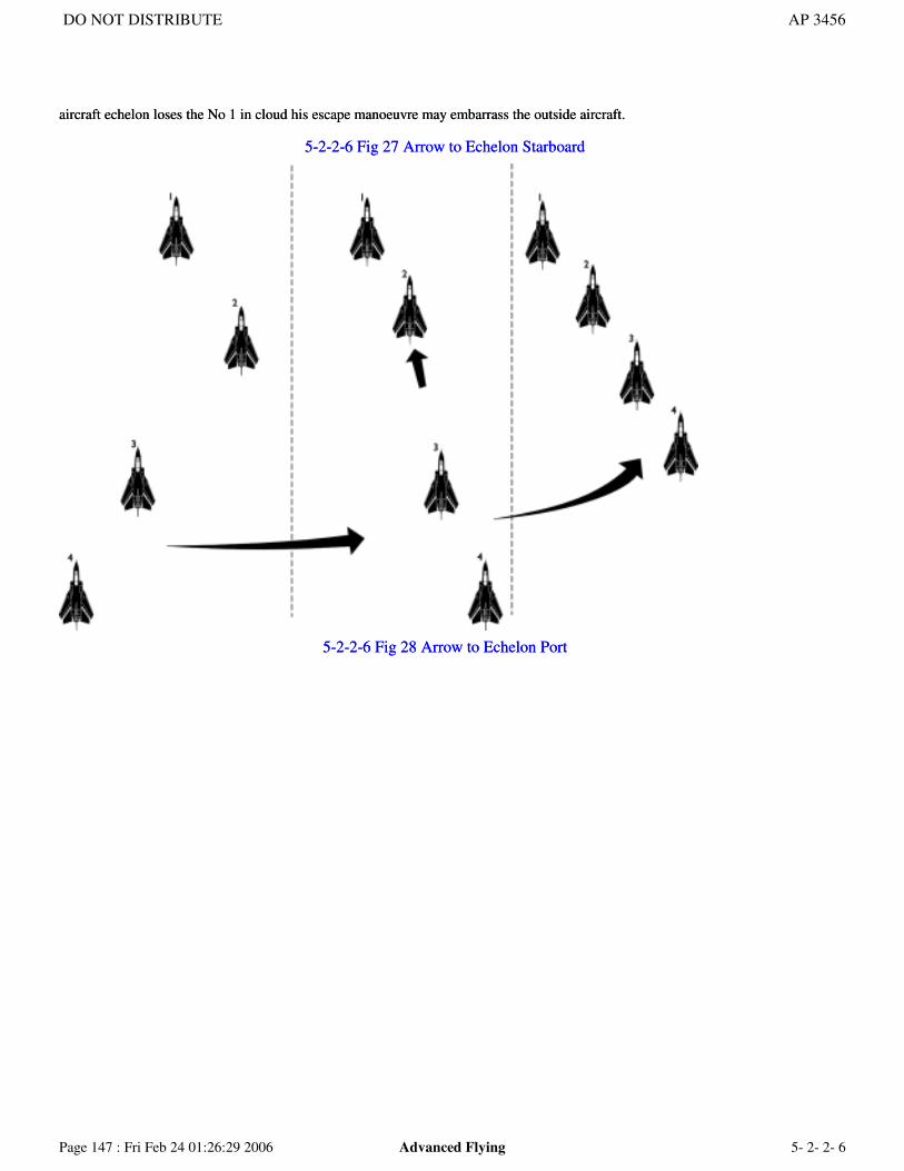
aircraft echelon loses the No 1 in cloud his escape manoeuvre may embarrass the outside aircraft.
5-2-2-6 Fig 27 Arrow to Echelon Starboard
5-2-2-6 Fig 28 Arrow to Echelon Port
aircraft echelon loses the No 1 in cloud his escape manoeuvre may embarrass the outside aircraft.
5-2-2-6 Fig 27 Arrow to Echelon Starboard
5-2-2-6 Fig 28 Arrow to Echelon Port
DO NOT DISTRIBUTE AP 3456
Page 147 : Fri Feb 24 01:26:29 2006 Advanced Flying 5- 2- 2- 6

5-2-2-6 Fig 29 Defensive Battle through Arrow to Echelon Starboard Formation5-2-2-6 Fig 29 Defensive Battle through Arrow to Echelon Starboard Formation
DO NOT DISTRIBUTE AP 3456
Page 148 : Fri Feb 24 01:26:29 2006 Advanced Flying 5- 2- 2- 6
5-2-2-6 Fig 30 Defensive battle through Arrow to Echelon Port Formation5-2-2-6 Fig 30 Defensive battle through Arrow to Echelon Port Formation
DO NOT DISTRIBUTE AP 3456
Page 149 : Fri Feb 24 01:26:29 2006 Advanced Flying 5- 2- 2- 6
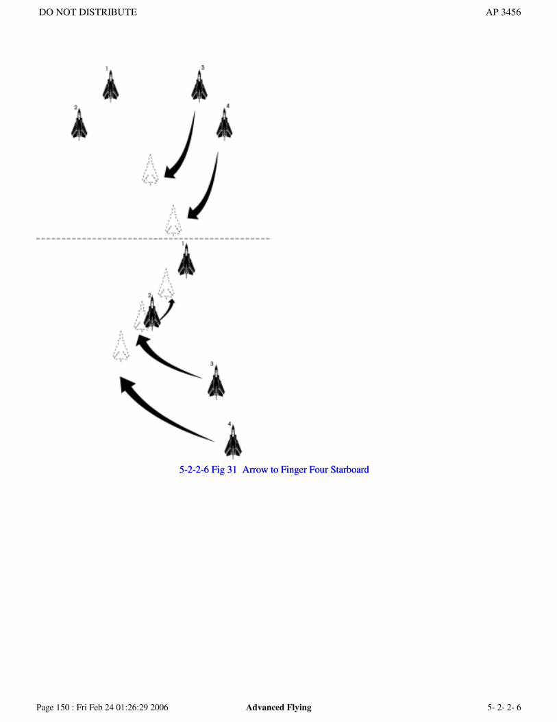
5-2-2-6 Fig 31 Arrow to Finger Four Starboard5-2-2-6 Fig 31 Arrow to Finger Four Starboard
DO NOT DISTRIBUTE AP 3456
Page 150 : Fri Feb 24 01:26:29 2006 Advanced Flying 5- 2- 2- 6

2-2-6 Fig 32 Arrow to Finger Four Port2-2-6 Fig 32 Arrow to Finger Four Port
DO NOT DISTRIBUTE AP 3456
Page 151 : Fri Feb 24 01:26:29 2006 Advanced Flying 5- 2- 2- 6
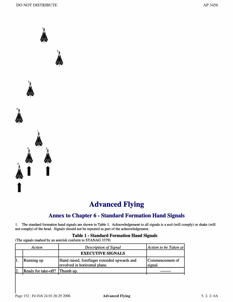
Advanced Flying
Annex to Chapter 6 - Standard Formation Hand Signals
1. The standard formation hand signals are shown in Table 1. Acknowledgement to all signals is a nod (will comply) or shake (willnot comply) of the head. Signals should not be repeated as part of the acknowledgement.
Table 1 - Standard Formation Hand Signals(The signals marked by an asterisk conform to STANAG 3379)
Action Description of Signal Action to be Taken at
EXECUTIVE SIGNALS
1. Running up Hand raised, forefinger extended upwards andrevolved in horizontal plane.
Commencement ofsignal.
2. Ready for take-off? Thumb up. --------
DO NOT DISTRIBUTE AP 3456
Page 152 : Fri Feb 24 01:26:29 2006 Advanced Flying 5- 2- 2- 6A

3. Commence take off. Chopping motion forwards with edge of flat hand,fingers together or forward nod of the head(preceded as a warning by a tap on the head withhand.)
Cessation of signal.
4. a. Increase power. a. Positive forward movement of head. Cessation of signal.
b. Decrease power b. Positive backward movement of head.
5. Turning. Forearm vertical, hand flat and parallel with line offlight then moved right or left as necessary.
Cessation of signal.
6. Straightening out. Chopping motion forwards with edge of flat hand -as for 3.
Cessation of signal.
7. Airbrakes “in” or“out”.*
Biting motion with hands, fingers and thumbmeeting and opening alternatively.
Nod of head.
8. Flaps “up” or“down”.*
Hands flat, fingers forward; downward motion ofhand from wrist to lower flaps; reverse motion toraise flaps.
Nod of head.
9. Undercarriage “up”or “down”.*
Hold hand with closed fist near the top of canopyand then move hand vertically downwards andupwards three times.
Nod of head.
10. Take over asleader.*
Point to new leader, then hold open hand verticallyat eye level, fingers together, and then move ithorizontally forward to finish with arm fullyextended and hand pointing forward.
Cessation of signal.
11. Close formation orreform basicformation as briefed.
Lateral rocking of aircraft. Cessation of signal.
12. Relax closeformation.
Hand raised with palm outwards, fingers together,palm against canopy on the appropriate side.
Cessation of signal.
13. Change position .* Forefinger pointed at aircraft concerned, thenpointed to the new position to which this pilot is tomove.
Cessation of signal.
14. Line astern:
a. Close a. Clenched fist, thumb extended to rear, movingback and forth.
Cessation of signal.
b. Extended b. Clenched fist, tapping on the back of head.
15. Climbing. Forefinger point upwards. Cessation of signal.
16. Descending. Forefinger pointing downwards. Cessation of signal.
17. Levelling out. Sideways movements of either hand, palm down,fingers extended at face level.
Cessation of signal.
18. Break formation. Rapid sweeping movement of the open hand, palmforward, fingers upward in front of the face.
Cessation of signal.
19. I am returning/youare return to base.
Point at self/aircraft concerned, then pointdownwards.
--------
INFORMATIVE SIGNALS
20. Your aircraft is onfire.
Fly alongside and rock the wings to attract theattention of the pilot, then draw the edge of thehand across the throat in a cutting motion,
--------
DO NOT DISTRIBUTE AP 3456
Page 153 : Fri Feb 24 01:26:29 2006 Advanced Flying 5- 2- 2- 6A

afterwards pointing to the fire area.
Continue this until acknowledged by thumbs upsignal.
21. Fuel state.* --------
a. Demand. a. Make drinking motion with closed hand, thumbextended towards mouth.
b. Reply. b. Indicate estimated flying time remaining byextending fingers, one finger to indicate 10-19mins, two, 20-29 mins, up to five fingersmeaning 50 mins to one hour. Five fingersfollowed by three fingers means one hour thirty(to thirty-nine) minutes.
DISTRESS SIGNALS (DAY)
22. Bailing out.* One or both clenched fists pulled downwards, fromacross the face to simulate pulling ejection blind.
--------
23. Desire to land.* Movement of the hand, flat, palm downwards, fromabove the head forwards and downwards, finishingthe movement in a simulated round-out.Alternatively, lower the undercarriage.
--------
24. Systems failure(HEFOM).*
Pilot will clench the fist and hold it in to the top ofthe canopy; after passing this signal he will hold upthe required number of fingers to denote the systeminvolved (see below).
--------
a. Hydraulic - one finger.
b. Electrical - two fingers.
c. Fuel - three fingers.
d. Oxygen - four fingers.
e. Motor - five fingers.
NOTE:
1. The HEFOM signals are to be used onlywhen radio contact is not possible.
2. If either the one finger signal is received orthe intercepting pilot is unable to understandthe signals of the pilot requiring assistance, thenthe intercepting pilot is to assume that theaircraft in distress has one or more systemsinoperative, eg airbrakes, flaps orundercarriage, and is to proceed with extremecaution.
25. Receiver failure.* Tap earphone with open hand and then move handforward and backward over ear position.
--------
26. Transmitter failure.* Tap microphone and then move hand up and downin front of face.
--------
DISTRESS SIGNAL (NIGHT)
27. In distress and Repeated intermittent flashes with a torch, taking --------
DO NOT DISTRIBUTE AP 3456
Page 154 : Fri Feb 24 01:26:30 2006 Advanced Flying 5- 2- 2- 6A
desire to land.* care not to dazzle other pilots. (The lead aircraftshould assume that the aircraft in distress has one ormore inoperative systems and proceed with extremecaution.)
NOTE:
Because night signals will be difficult tounderstand, only the night signal given above willbe used.
Advanced Flying
Chapter 7 - Air-to-Air Refuelling
Introduction
1. One of the major problems that has always faced designers of aircraft is how to increase range without sacrificing other aspects ofperformance. If provision is to be made for the carriage of additional fuel then there must be a weight penalty in the basic structurewhich in turn affects either the height, speed, manoeuvrability or take-off and climb performance that can be achieved. One solutionto the problem is the use of Air-to-Air Refuelling (AAR). Its adoption by the RAF has been so extensive that almost all aircraftintroduced into service today are given a flight refuelling facility.
2. The primary task of the Tanker Force is the support of aircraft directly committed to the NATO alliance. Priority is given toaircraft operating in the Air Defence role. For geographical reasons, short range interception is less important to Great Britain thanlong range combat air patrols (CAP), clearly AAR provides the endurance required for this concept.
3. Although long range strategic deployments attract publicity, and would seem to epitomize AAR, in fact, the priority, indescending order is:
a. Support of Air Defence Aircraft.
b. Support of Interdictor Strike Aircraft.
c. Tactical support of Maritime Operations.
d. Overseas support, deployments and exercises.
However, situations occur where the swift deployment of aircraft to counter a distant threat is a vital factor in military operations.Without AAR the speed of response would be seriously affected.
Refuelling Equipment
4. There are two main methods of transferring fuel from the tanker to the receiver aircraft; the Boom, and the Probe and Drogue.
5. The Boom Method. The boom method was developed by the USAF, mainly for refuelling their bombers, and became operationalin 1949. The boom is a telescopic metal tube fitted underneath the tanker fuselage and equipped with flying control surfaces. Tomake contact the tanker boom operator “flies” the end of the boom into the refuelling receptacle of the receiver formating behind andbelow the tanker.
6. The Probe and Drogue Method. The probe and drogue method is a British development and is now in operational service withmany air forces, including the RAF. From a power-driven drum the tanker trails a hose at the end of which is the drogue (Fig 1), aribbed light alloy and nylon collapsible conical basket. The ribbing and shape of the drogue gives it aerodynamic stability and thenylon material keeps the mouth of the drogue open. When fully extended the hose is automatically “balanced” by varying the torqueof the motor until it almost counteracts the drag of the drogue in the slip-stream. The receiver has a probe mounted on the nose of the
DO NOT DISTRIBUTE AP 3456
Page 155 : Fri Feb 24 01:26:30 2006 Advanced Flying 5- 2- 2- 7

aircraft or leading edge of the wing and connected to the normal fuel system. The probe may be fixed or retractable.
5-2-2-7 Fig 1 Typical Reception Coupling and Drogue
7. To make contact the receiver pilot flies his probe into the drogue while maintaining a closing speed of 2 to 5 kt. When the probemakes contact with the reception coupling in the drogue, the probe nozzle is gripped by spring-operated toggles which make afuel-tight joint and automatically opens the fuel passage between the two aircraft. As the receiver continues to close on the tanker, thehose is wound onto the drum and prevents it becoming slack and forming a loop. When a few feet of hose have been wound in, themain fuel valve in the tanker opens and fuel is pumped to the receiver. At the same time the lock between the probe nozzle andreception coupling is reinforced hydrostatically by the flow of fuel. On completion of fuel transfer the receiver pilot breaks contact byclosing his throttles slightly, dropping back very gently until the hose is fully extended and the probe is pulled out of the receptioncoupling.
8. Adjacent to the refuelling unit and facing aft, the tanker has a panel of coloured lights (red, amber and green). Amber indicates tothe receiver pilot when it is clear to make contact, green indicates that the fuel valve is open and the red light indicates that contact isto be broken immediately or that no attempt is to be made to make contact. If required, refuellings can be made in radio silence solelyby reference to these signal lights. Lighting equipment on the tanker, and probe lighting on some receivers, enable the refuelling to bedone at night.
9. To give greater flexibility of operation, the size of the probe nozzle and reception coupling have been standardized throughoutNATO countries. In addition, the boom method (used mainly by the USAF) can be adapted for use by receivers equipped with probesby attaching a short length of hose and a drogue to the end of the boom.
Equipment Currently in Use in the RAF
10. The RAF tanker fleet consists of tanker conversions of the VC 10, and Tri-Star aircraft. Some squadrons can operate a ‘buddy’
DO NOT DISTRIBUTE AP 3456
Page 156 : Fri Feb 24 01:26:30 2006 Advanced Flying 5- 2- 2- 7

system of AAR. This concept consists of two aircraft, one carrying the military payload, the other the refuelling pod. At abouttwo-thirds of the distance to the target, fuel is transferred to the receiver aircraft, the tanker returns to base.
5-2-2-7 Fig 2 Cut-Away View of Mk 32 Pod
11. The actual refuelling units themselves are of two types, the hose drum unit (HDU) and the underwing pod. The HDU is mountedat the rear of the fuselage and has a higher rate of flow than the pod. The HDU is primarily intended for use by tanker or transportaircraft but can be used by any type.
AIRCRAFT HDU POD
Tornado One Mk 20H
VC 10 K2/3/4 One Mk 17B Two Mk 32
VC10 C1K Two Mk 32
Tri-Star Two Mk 17T
12. The Mk 20H Underwing Pod. The Mk 20H underwing pod is a self-contained, hydraulically-operated unit requiring onlyelectricity, fuel and air supplied from the tanker. Sequencing of the pod operation is achieved by means of a solenoid operatedselector switch known as a “Ledex”. The entire power is provided by a featherable ram air turbine in the nose of the unit which drivesa two-stage fuel pump and a hydraulic pump. In the centre section is a fuel tank which is replenished from the tanker’s main fuelsystem as fuel is transferred through the hose. The rear section of the pod contains a hydraulically-powered hose drum unit. Adetachable fairing encloses the hose reel and provides storage for the collapsible drogue which folds when the hose is retracted. The
hose drum unit carries 51 ft of 11
2 in bore hose and the unit can deliver up to 567 kg (1,250 lb) of fuel per minute at a pressure of 50
psi. The complete unit is remotely controlled by the operator from a small panel in the cockpit.
13. The Mk 32 Underwing Pod. (Fig 2). This is a development of the Mk 20, requiring only access to fuel and a 28v dc electricalsupply. It has no internal fuel tank and draws all fuel during AAR operations directly from the tanker’s fuel system. This allows thestructure to be less robust and therefore lighter than the Mk 20. Automatic sequencing of the pod operation is achieved by means ofelectronic logic circuits. The featherable ram air turbine drives a fuel pump and a vane/pump motor. The vane/pump motor providesthe drive to the hose drum unit for hose trailing and winding. The system is supplemented by a tensator unit which consists of 8 largecoiled springs which, during hose trailing, wind up onto a central spool connected to the hose drum unit. The energy of the tensatorthus provides the “balancing force” against drogue drag during fuel transfer. The hose drum unit carries 55 ft of 2 in bore hose andthe unit can deliver up to 1270 kg (2,800 lb) of fuel per minute at a pressure of 50 psi. Remote control by the operator is by a smallpanel in the tanker cabin. Refuelling from underwing pods is shown in Fig 3.
5-2-2-7 Fig 3 Refuelling from Underwing Pods
DO NOT DISTRIBUTE AP 3456
Page 157 : Fri Feb 24 01:26:30 2006 Advanced Flying 5- 2- 2- 7

14. The Mk 17B Hose Drum Unit (Fig 4). The Mk 17B hose drum unit is fitted at the rear of the fuselage. Automatic sequencing ofoperation is by a similar “Ledex” system to the Mk 20 pod. The hose drum is powered by an electric motor, the torque output beingcontrolled by a variable scoop fitted in the fluid flywheel assembly. Fuel is supplied from the tanker’s high capacity booster pumps;the pressure normally being increased by a pump coupled to a bleed-air turbine supplied from the main engine compressors. The hosedrum unit carries 80 ft of 3 in bore hose which can deliver up to 2177 kg (4,800 lb) of fuel per minute at a pressure of 50 psi. Theunit is remotely controlled by the operator from a panel in the tanker cabin. Refuelling from a Tri-Star hose drum unit (Mk 17T) isshown in Fig 5.
FLYING TECHNIQUES
Tanker Aircraft
15. While a receiver is approaching the drogue the tanker aircraft should be flown as smoothly as possible because any movement ofthe aircraft will cause the drogue to oscillate and reduce the chances of a successful contact. It is incumbent upon the tanker captain,therefore, to find the best possible flying conditions conducive to a receiver making contact, ie air space relatively free from cloud orclear air turbulence. When a receiver is in contact, it is usually possible to hold position in all but the most turbulent conditions. Atall times however, the tanker should be as stable as possible; turns may be made but they should be made smoothly and at such a rateas to allow the receiver to remain in contact easily.
5-2-2-7 Fig 4 Mk17B Hose Drum Unit
DO NOT DISTRIBUTE AP 3456
Page 158 : Fri Feb 24 01:26:30 2006 Advanced Flying 5- 2- 2- 7

5-2-2-7 Fig 5 Refuelling from a Mk17T Hose Drum Unit
16. Once a receiver has joined the tanker, the tanker captain assumes executive control of both aircraft. On large formations during
5-2-2-7 Fig 5 Refuelling from a Mk17T Hose Drum Unit
16. Once a receiver has joined the tanker, the tanker captain assumes executive control of both aircraft. On large formations during
DO NOT DISTRIBUTE AP 3456
Page 159 : Fri Feb 24 01:26:30 2006 Advanced Flying 5- 2- 2- 7

accompanied flights the lead tanker captain is responsible for the safety aspects of the formation. In the event of a receiver emergencythe course of action to be taken by the receivers is determined by the receiver leader.
Receiver Aircraft
17. The techniques for successful receiver flying are not difficult to acquire and are well within the capability of the average pilot.Techniques vary slightly but accurate and smooth flying is the basis for success for all types of receiver aircraft. The drogue isapproached from behind and slightly below at an overtaking speed of 2 to 5 kt, care being taken in the final stage of the approach notto overcorrect on the controls. If the receiver makes contact too slowly the probe will not engage correctly in the coupling; this istermed a “soft” contact. If an approach is made too fast the drum will not be able to take up the hose quickly enough, the hose willbow and the resulting whip will probably break off the probe nozzle. Terminology used includes a ‘spokes contact’, defined as thereceiver probe penetrating the ribs or canopy of the drogue, causing damage which can cause FOD and may cause the drogue to loseaerodynamic stability; further attempts to make contact are then not permitted. A ‘rim contact’ is made when the probe makes a hardcontact on the rim of the drogue but does no damage.
18. When at the end of an approach and the receiver is sure of making contact, a small amount of power is applied to counteract thedrag from the drogue and to maintain the correct closing speed. Immediately a successful contact has been made and the probe isobserved to be positively locked in the drogue, a definite reduction in closing speed should be made by slightly closing the throttlesbefore moving up the refuelling position. The normal refuelling position, and one giving the largest refuelling flight envelope, iswhen the hose is lying at its normal trail angle with the forward edge of the orange band marked on the hose just entering the mouthof the pod, or the serving carriage of the HDU. In all types of receiver aircraft it is essential that pilots are capable of close formationflying for periods of ten minutes of more.
19. To break contact the throttles are closed slightly and the receiver allowed to drop gently back along the line of the hose with theaim of breaking contact with the drogue in the normal full trail position. In an emergency the throttles are fully closed and, because ofthe hose drum braking system, contact will be broken almost immediately with the hose partially wound on the drum.
Night Refuelling
20. Apart from requiring greater concentration, the techniques for night refuelling are identical to those used by day. Any additionaldifficulties are due mainly to the inability to judge final closing speeds and the distance of the probe from the drogue owing to lack ofoutside references. To assist the receiver pilot, the serving carriages are lit and the drogue canopy has beta lights around the rim. Theunderside of the tanker fuselage and wings are illuminated to provide a horizontal reference. Most receivers also carry lights toilluminate the probe so that it can be seen clearly.
OPERATIONAL USE OF AAR
Methods of Employment
21. Tactical Applications. As stated in para 2, extending the radius of action of aircraft on operational sorties is possibly the mostimportant application of AAR. The developing range of operational requirements means a continuing process in evolving the tacticalprocedures necessary to make the best use of the available effort. For instance, the role of the air defence tanker (ADT), in support ofthe fighter on a CAP has increased in importance due to changing fighter tactics and the need to provide air defence over maritimeareas. Method of close support of strike aircraft, such as the Tornado, would change with each particular attack sortie due to thevariety and location of targets. Inevitably, such wide variations in operational requirements make flexibility paramount for anefficient Tanker Force. Similarly, detailed tanker Standard Operating Procedures (SOPs) are essential to cover every likely operatingcondition.
22. Overseas Reinforcement. There are two ways in which AAR can be used for aircraft deployment: accompanied andunaccompanied flights
a. Accompanied Flight. On accompanied flights the receivers make a rendezvous with the tanker close to the receivers’ airfieldof departure. Thereafter the receivers remain in close proximity to the tanker, taking fuel as planned, until they reach theirterminal airfield. In normal peace-time operations the refuellings en route are planned so that, if for some reason the receivers areunable to take on fuel, they have sufficient fuel remaining to either return to their departure airfield or divert to a suitable airfieldnear track. Accompanied flight is usually employed when the receiver aircraft have poor navigation or communications facilitiesand/or a short ferry range, eg fighter-type aircraft. After the last refuelling the receivers may leave the tanker and continue to
DO NOT DISTRIBUTE AP 3456
Page 160 : Fri Feb 24 01:26:30 2006 Advanced Flying 5- 2- 2- 7

their destination independently. In this way, by flying at their own optimum speeds and heights rather than those of theformation, the receivers’ range may be increased by 50 to 100 nm. This “departure” by the receivers may also be used when thetanker is required to land at an airfield other than the receivers’ destination.
b. Unaccompanied Flight. On unaccompanied flights the receiver makes a rendezvous with the tanker at a convenient pointalong its track to the destination airfield. For maximum benefit the refuelling should take place at a point as far as possible fromthe airfield of departure commensurate with aircraft safety. After refuelling, the receiver proceeds alone to its destination.Although this method may be used with long range fighters, it is usually restricted to aircraft with good navigation andcommunications facilities and/or a large internal fuel capacity, eg bomber or transport aircraft.
Rendezvous Procedures
23. There are three main methods of effecting a rendezvous (RV):
a. Pure Navigation Technique. By this method both the tanker and receiver use their own internal navigation systems to placethemselves at a planned position and flight level at a predetermined time, thereafter depending on visual sighting to makecontact.
b. Air Transported Rendezvous Aids. Information obtained from three types of airborne equipment is used to aid therendezvous. From a display of range and bearing of the receiver from the tanker, the tanker crew can direct the receiver to withinvisual sighting range. The equipments used are
(1) TACAN air-to-air mode in both tanker and receiver provides the range and in some modern sets a magnetic bearing.
(2) Collins UHF D/F carried in all tanker and some receiver types provides relative bearing of the receiver from the tankerand vice versa by monitoring the other aircraft’s UHF transmissions.
(3) AI equipment carried by fighter aircraft.
In the event of an equipment failure emergency procedures are available to assist the rendezvous.
c. Ground Controlled Rendezvous. When the rendezvous position is within ground radar cover, the receiver can be directedonto the tanker using normal GCI techniques.
The basic principle to be observed in the selection of a rendezvous position is that the receiver should be diverted as little as possiblefrom the direct route to its destination.
Meteorological Aspects
24. Weather has an important influence on the conduct of AAR operations. In addition to taking account of the weather conditionsat the operating and diversion airfields the following factors have to be considered.
a. Rendezvous Weather. Weather conditions in the actual area of the rendezvous can be critical. Although it is not impossibleto make a rendezvous in thin cloud, it is much more difficult and hazardous than in clear conditions. A visual sighting can bemade much more easily if the rendezvous is at a height at which contrails are found.
b. En Route Weather. During accompanied flights IMC can make visual station keeping in large formations very difficult.Although the internal radar of the tankers and receivers can be used to assist station keeping in cloud, such conditions are avoidedas far as possible by small deviations in route and/or height. Contacts may be made in cloud but flight in heavy cumulo-nimbusformations or clear air turbulence can result in drogue oscillation and difficulties in making contact.
Planning
25. Before a deployment may be undertaken, it must be established that it is feasible. The purpose of the feasibility study is
DO NOT DISTRIBUTE AP 3456
Page 161 : Fri Feb 24 01:26:30 2006 Advanced Flying 5- 2- 2- 7
two-fold: to establish that the receiver is capable of undertaking the deployment format and to establish the tanker/receiver ratiorequired. Many factors are taken into account: the relative performance of the tanker and receiver aircraft, the availability of diversionairfields along the selected routes, the tanker effort allocated to the deployment, the availability of parking space at the stagingairfields, and the climatology of the route and the staging and terminal bases. Receivers can normally be classified as highperformance aircraft and in many cases the endurance is, apart from fuel, limited by the consumption of oil and oxygen. Theendurance of the receiver frequently dictates the format of the deployment.
26. When the feasibility study has been completed, it is then possible to calculate the movement table which provides details of thedaily movements of tankers and receivers. From this the personnel and equipment needed at en route bases for ground support can bedetermined.
The Refuelling Plan
27. When the tanker movements have been determined, the full refuelling plan is calculated; this plan sets out:
a. The positions where fuel is to be transferred to the receivers.
b. The quantity of fuel to be transferred.
c. The Abort Point (AP) - this is a geographical position on a receiver’s track associated with a specific refuelling bracket.Should a receiver reach an AP without the planned transfer for the appropriate bracket having commenced, diversion action mustbe taken. This will allow the receiver to arrive overhead the planned diversion with the minimum fuel reserve.
d. The nominated diversion airfields to be used if a planned fuel transfer fails for any reason or if diversion is necessary forother contingencies.
e. The fuel remaining in the tanker after each transfer, and overhead the planned destination airfield.
Conclusion
28. AAR was introduced into the RAF to assist in strategic deployment about the world. As the threat changes and globalcommitments alter, so the role of AAR changes. The term ‘force multiplier’ has been applied to AAR and perhaps that sums up themodern concept of air-to-air refuelling. By this relatively simple technique the effectiveness of limited forces can be increasedconsiderably.
Advanced Flying
Chapter 8 - Asymmetric Flight and Engine-out Performance
Introduction
1. Asymmetric flight is generally accepted to mean the condition applying to multi-engined aircraft, following loss of power froman engine(s) mounted laterally either side of the centre line. Unusual configurations are not considered in the discussion on handling,although the degradation of performance obviously applies. The term ‘multi-engined’ in this chapter means more than one powerplant.
2. Aircrew Manuals give details of the technique and speeds required when using asymmetric power, the information in this chapterbeing of a general nature. It is emphasized that Aircrew Manuals, JSP 318 (Military Flying Regulations) and the Flying Order Bookshould be studied before practising the use of asymmetric power.
Basic Conditions
3. If a multi-engined aircraft suffers engine failure when airborne, there are two immediate effects:
DO NOT DISTRIBUTE AP 3456
Page 162 : Fri Feb 24 01:26:30 2006 Advanced Flying 5- 2- 2- 8
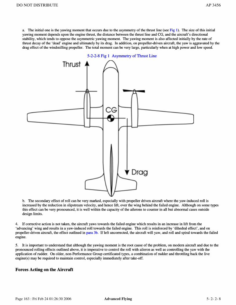
a. The initial one is the yawing moment that occurs due to the asymmetry of the thrust line (see Fig 1). The size of this initialyawing moment depends upon the engine thrust, the distance between the thrust line and CG, and the aircraft’s directionalstability, which tends to oppose the asymmetric yawing moment. The yawing moment is also affected initially by the rate ofthrust decay of the ‘dead’ engine and ultimately by its drag. In addition, on propeller-driven aircraft, the yaw is aggravated by thedrag effect of the windmilling propeller. The total moment can be very large, particularly when at high power and low speed.
5-2-2-8 Fig 1 Asymmetry of Thrust Line
b. The secondary effect of roll can be very marked, especially with propeller driven aircraft where the yaw-induced roll isincreased by the reduction in slipstream velocity, and hence lift, over the wing behind the failed engine. Although on some typesthis effect can be very pronounced, it is well within the capacity of the ailerons to counter in all but abnormal cases outsidedesign limits.
4. If corrective action is not taken, the aircraft yaws towards the failed engine which results in an increase in lift from the‘advancing’ wing and results in a yaw-induced roll towards the failed engine. This roll is reinforced by ‘dihedral effect’, and onpropeller-driven aircraft, the effect outlined in para 3b. If left uncorrected, the aircraft will yaw, and roll and spiral towards the failedengine.
5. It is important to understand that although the yawing moment is the root cause of the problem, on modern aircraft and due to thepronounced rolling effects outlined above, it is imperative to control the roll with aileron as well as controlling the yaw with theapplication of rudder. On older, non-Performance Group certificated types, a combination of rudder and throttling back the liveengine(s) may be required to maintain control, especially immediately after take-off.
Forces Acting on the Aircraft
DO NOT DISTRIBUTE AP 3456
Page 163 : Fri Feb 24 01:26:30 2006 Advanced Flying 5- 2- 2- 8

6. An aircraft can maintain a constant heading under asymmetric power with an infinite number of bank and sideslip combinations,ie of aileron and rudder settings. This is apparent from the consideration of the yawing and rolling moments and the side forcesacting on the aircraft.
7. The forces acting on the aircraft, in the plane of the wings are:
a. The sideforce on the body and fin, due to sideslip. The total contribution is stabilizing, and will act behind the CG.
b. The sideforce on the rudder hinges, caused by rudder deflection, pivoting the aircraft about the CG.
c. Any lateral component of lift, produced by banking.
d. Thrust from the live engine(s).
e. Total drag.
8. In addition to these major factors, in the case of propeller-driven aircraft, there are the minor, but appreciable, effects of:
a. Torque. Propeller torque, which increases with power, tends to roll the aircraft in the opposite direction to that of propellerrotation. Torque has a slight effect on the margin of control while using asymmetric power; if the torque reaction tends to lift thedead engine, then its effect is beneficial. On aircraft having contrarotating propellers there is no torque effect, since the torque ofeach half of the propeller counteracts the other.
b. Asymmetric Blade Effect. When the plane of rotation of the propeller is not at right angles to the flight path the centre ofthrust of the propeller does not coincide with the centre of the disc. For example, if the left propeller rotates anti-clockwise whenviewed from the rear and the propeller disc is tilted upwards relative to the airflow, as when flying at a low IAS and hence a highnose-up attitude, then the down-going blade (ie on the left side of the disc) will experience a greater angle of attack than theup-going blade. The thrust line will be displaced to port, increasing the yawing moment.
c. Slip-Stream Effect. One engine can have a greater effect than the other on the yawing characteristics of the aircraft:depending on the direction of rotation of the propeller, the spiral path of the slipstream meets the fin and rudder at an angle ofattack.
d. Drag of Failed Propeller. The amount of drag will depend on whether the failed propeller has been feathered; a windmillingpropeller gives more drag than a feathered one and therefore the total drag of the aircraft is increased and displaced towards thefailed engine.
Balanced Flight
9. In straight and level, unaccelerated flight all forces acting on the aircraft, in all 3 axes, are balanced and the moments inequilibrium. The forces can be shown to be balanced either by a simple Lift = Weight or, for a more complex arrangement of forces,that they vectorially form a closed polygon. An imbalance of forces will cause the aircraft to change its flightpath, ie climb, descendor turn. When the moments are balanced, the aircraft’s attitude remains unchanged. When discussing the forces involved inasymmetric flight only the forces and moments acting in the normal (yawing) and longitudinal (rolling) planes are considered. This isbecause the initial reaction of an aircraft suffering the effects of asymmetric power is to yaw and then roll. All the inputs are tocounter the initial yaw and the further or subsequent effects.
10. Wings Level (Fig 2a). Following an engine failure in symmetrical flight, because the thrust and drag lines are now offset inrelation to the centre of gravity (CG), the aircraft will yaw towards the failed engine. The further effect of yaw is roll, also towardsthe failed engine. If the aircraft is propeller driven the loss of lift from the lack of slipstream can be quite marked. This will causeroll and then further yaw all towards the failed engine. Furthermore, whereas the effects described in para 8 may also have an effect,in particular if feathering action is not taken quickly, the high drag from the windmilling propeller will markedly affect the yaw/rollreaction. To oppose the initial yaw the rudder is applied. This momentary stage leads to an imbalance of forces. Thrust is acting inthe original direction of flight and the rudder side force is acting towards the side of the failed engine causing the aircraft to start tosideslip away from the original flightpath. To counteract this the aircraft must be yawed through an angle equivalent to the sideslipangle. In addition, because of the sideslip, the static (weathercock) stability of the aircraft tends to turn the aircraft into the relative
DO NOT DISTRIBUTE AP 3456
Page 164 : Fri Feb 24 01:26:30 2006 Advanced Flying 5- 2- 2- 8

airflow, thus requiring even more rudder sideforce to counter the weathercock force. To maintain a constant heading the ruddermoment is opposing the thrust/drag and weathercock moments. Initial roll is countered by aileron. As the aircraft starts to sidesliptowards the failed engine its static stability in roll, known as dihedral effect, will roll the aircraft away from the failed engine.Directional stability (weathercock effect), which is determined by fin size and position, provides a rolling moment away from thefailed engine. The rudder side force acts about the rudder hinge line which is usually above the centre of gravity and thereforeprovides an opposing rolling moment towards the failed engine. As far as the pilot is concerned, the asymmetric problem presentedby these complicated opposing forces is relatively easy to handle. He will use the rudder to counter any yaw and ailerons to keep thewings level. Both controls will be deflected away from the failed engine and the slip ball will be in the middle. By this means,passengers should not notice any discomfort and the lashings for freight will not be subjected to extra lateral strains.
5-2-2-8 Fig 2 Forces Acting in Asymmetric Flight
11. Small Bank Angle (Fig 2b). If, using the wings level method, speed in level flight continues to decay, the use of moreasymmetric power may be necessary. If no more power is available more and more rudder (and aileron) will be required to maintainstraight flight as the speed decays until full rudder deflection is reached. As speed reduces further the rudder side force will alsoreduce and the aircraft will again yaw towards the failed engine. It is unlikely that full aileron deflection will also have been reachedtherefore any tendency to roll can be easily countered. To oppose the divergence towards the failed engine the aircraft may be bankedaway from it using the horizontal component of lift to prevent the aircraft turning towards the failed engine. The more the bank isapplied the more the sideslip angle is reduced which, in turn, causes the weathercock force to reduce. Fig 2b shows the situationwhen zero sideslip angle is achieved. The reduced lift vector will require an adjustment to angle of attack to maintain level flight butthe smaller sideslip angle resulting from a bank angle up to 5° should improve performance overall. The balance of rolling momentsis between rudder and ailerons. Especially on a propeller driven aircraft, the aileron deflection may be quite large because the aileronsare also being used to pick up the wing following the loss of lift through lack of propeller slipstream. The aircraft will be flyingstraight and level but with a wing down; therefore the slip ball will be slightly displaced towards the live engine. Passengers will beslightly uncomfortable and any freight will strain against its lashings.
DO NOT DISTRIBUTE AP 3456
Page 165 : Fri Feb 24 01:26:31 2006 Advanced Flying 5- 2- 2- 8

12. Rudder fixed or Free (Fig 2c). If, for some reason, the rudder is not available even more bank is needed to compensate for theloss of rudder side force - using a larger horizontal component of lift to maintain straight flight. However, as the extra bank is appliedthe aircraft will start to sideslip away from the failed engine. This will create a weathercock force towards the failed engine. Thethrust/drag moment is opposed by the weathercock moment. The effect of the moment created by the horizontal component of liftwill depend on whether the centre of pressure is ahead of or behind the CG. It is not a strong moment, however, because its arm isrelatively short. The static lateral stability (dihedral effect) and weathercock rolling moment are towards the failed engine. They arecountered by an increased rolling moment generated by greater aileron deflection. Although this method is aerodynamically sound, itis the most uncomfortable for passengers and will provide the maximum strain on freight lashings. Furthermore, it is the mostdifficult to fly accurately especially on instruments, the slip ball being well displaced towards the live engine.
13. Drift Down. If an aircraft suffers an engine failure above the stabilizing altitude, after recovery to straight flight, it may beallowed to drift down to at least the stabilizing altitude given in the Aircrew manual or ODM at which it is possible to achieve andsubsequently maintain the recommended asymmetric speed in level flight. Limitations and regulations on drift down for scheduledperformance aircraft are given in Vol 1, Pt 3, Sect 4, Chap 4.
Rudder Response
14. It must be appreciated that the slip ball acts as a pendulum. In wings level controlled asymmetric flight it will be central, butwith up to 10° bank applied, the slip ball may be displaced up to one ball’s width towards the live engine. Full use should be made ofthe slip indicator in asymmetric flight, particularly when increasing power or manoeuvring. When manoeuvring from wings levelcontrolled flight the slip ball must be kept central, so that any unexpected deviation gives immediate warning of loss of directionalcontrol. If the slip indicator moves away from the central position in wings level flight and cannot be recentralized by rudder,sufficient bank towards the live engine must be applied or power must be reduced on the live engine or the nose must be lowered toincrease speed. A combination of all three may be necessary to regain control. The slip indicator is of paramount importance whenovershooting on asymmetric power because the danger of loss of control increases at low speeds and high power settings. It has beenshown that the aircraft’s response to the rudder is of prime importance for the prevention of yaw. Response to rudder by a givenaircraft depends on the IAS. If the IAS is decreased progressively whilst maintaining a constant power setting under asymmetricconditions, a speed will be reached below which the aircraft can no longer be directionally controlled with the rudder at its maximumdeflection. Below this speed the aircraft will yaw, and then begin to roll. Provided that aileron authority is available, directionalcontrol can still be maintained down to VMCA (see para 20).
IDENTIFICATION OF FAILED ENGINE
Turbojet
15. On turbojet aircraft, simple failures (eg flame-outs) are always shown by falling rpm and JPT. Internal mechanical enginefailures are sometimes masked by apparently normal engine indications, and engine vibrations may be the only clue to a possiblemechanical failure. In this case, it may be necessary to throttle back each engine in turn in an attempt to isolate the source ofvibration. When the vibrating engine has been identified, it should normally be closed down and not left at idling rpm.
Turboprop
16. Loss of power will be shown on the torque meter, confirmed by falling turbine inlet temperature. Except in the case of thefree-turbine engine, the drag from a windmilling propeller can be very large and some installations feather, or partially featherautomatically if the torque loss exceeds a certain figure.
SAFETY SPEED, VMCG AND VMCA
Factors Affecting Controllability
17. The factors affecting controllability are:
a. Power Output of Live Engine. As the force initiating the yaw is proportional to the thrust of the live engine, then for a givenIAS, more rudder is required to maintain directional control as the thrust is increased. Therefore, the higher the thrust from thelive engine, the higher is the IAS at which the pilot reaches full rudder deflection and directional control is lost.
DO NOT DISTRIBUTE AP 3456
Page 166 : Fri Feb 24 01:26:31 2006 Advanced Flying 5- 2- 2- 8

b. Critical Engine. The critical engine is that engine which, when failed, gives the greatest yaw. Due to slip-stream torque andasymmetric blade effects, one engine on propeller-driven aircraft may produce a greater adverse effect for the same settings thananother engine. On 4 engine aircraft an outboard engine will always be the critical engine due to the increased moment arm. Thedifference between port and starboard engine failed critical speeds on jet aircraft is usually small, and the critical engine speed isoften not defined by handling considerations.
c. Altitude. The thrust from the live engine for a given throttle setting decreases with height and therefore the asymmetric effectfor full power at altitude is less than at sea level.
d. Temperature. Temperature affects density and therefore the thrust from all engines is affected although this is more markedon a jet engine.
e. Weather Conditions. On a day with rough and gusty conditions the margin of control is reduced. If the rudder is almost fullyover in one direction, a very limited amount of movement is available for correction necessitated by air turbulence.
f. Loading (CG Position). The precise effect of the CG position is dependent upon the type of aircraft. With the CG at theforward limit the aircraft is more aerodynamically stable (see Vol 1, Pt 1, Sect 1, Chap 14, Para 12). A CG at the aft limit wouldhave the opposite effect because the control moment arm is reduced, the aircraft is less stable and less external force is requiredto disturb it. The greater the permissible limits in the travel of the CG, the larger the difference in aircraft handling in asymmetricflight. Provided the CG is within the limits no insurmountable handling difficulties should be encountered.
g. Flap Setting. The position of the flaps may have a marked effect on the airflow over the tail surfaces. As this effect variesbetween types, no general rule can be laid down. The effect on a particular type can be found by experiment; if it is significant itis mentioned in the Aircrew Manual.
h. Asymmetric Drag. Asymmetric drag on the same side as the dead engine may be produced by a windmilling propeller, seizedengine, or asymmetric external stores loading. This drag can be reduced by jettisoning stores or feathering the propeller of thefailed engine and placing such items as cooling shutters to the minimum drag position. (It should be noted that the minimumdrag position is not necessarily the fully closed position, but usually slightly open so that the surface of the adjustable shutter liesparallel to the local airflow.)
i. Strength and Skill of the Pilot. On many aircraft, when high thrust is being used at low speed, the foot loads are considerable,and whilst the pilot’s physical strength and leg length have an important bearing on the amount of rudder he can apply, so doesthe position and availability of trim tabs. VMCG and VMCA speeds limit the maximum rudder pedal force to 150 lb and do not
assume exceptional skill.
Safety Speed (V2)
18. Safety speed is the speed to which the aeroplane should be accelerated after take-off. It is a speed which provides a safe marginabove the stalling speed for the purposes of manoeuvre before the flap retraction height is reached and which also provides a safemargin above VMCA. It increases with all up weight. The ability to accelerate on asymmetric power depends on the amount of
power that can be used while control is retained and the reduction that can be made in drag. Engine failure in the most adverseconfiguration and at the highest weight, makes it essential that the drag be reduced to a minimum so that the aircraft can accelerate toa safe speed on the power available. The undercarriage and flaps should therefore be raised and jettisonable stores released as soon aspossible (as recommended in the Aircrew Manual).
VMCG (Minimum Control Speed - Ground)
19. VMCG is the minimum speed, under take-off power conditions, at which in the event of a sudden and complete failure of the
critical engine, it is possible to recover control with the use of rudder alone and without reducing power on the live engines. It willthen be possible to maintain a path parallel to the runway centreline, not more than 30 ft displaced from the centre-line. The effect ofnosewheel steering has been disregarded in the derivation of this speed, although the nosewheel is assumed to be in contact with theground. VMCG varies with airfield altitude and temperature.
VMCA (Minimum Control Speed - Air)
DO NOT DISTRIBUTE AP 3456
Page 167 : Fri Feb 24 01:26:31 2006 Advanced Flying 5- 2- 2- 8
20. VMCA is the minimum speed at which, in the event of sudden and complete failure of the most critical engine in the take-off
configuration, it is possible to maintain directional control and thereafter maintain steady flight using full rudder deflection and amaximum of 5° of bank away from the failed engine. VMCA varies directly with air density. NB. BCARs, Section D, defines the
‘V’ speeds in greater detail.
ENGINE FAILURE DURING TAKE-OFF (COMBAT AIRCRAFT)
Considerations
21. On transport aircraft, full control can be maintained after engine failure at any stage and the take-off continued if the failureoccurs after V1 (See Vol 1, Pt 3, Sect 4, Chap 1 ‘Introduction to Scheduled Performance’). The considerations of this part of the
chapter concerns aircraft on which control can be lost, or which have marginal climb performance, after an engine failure. This lattercategory includes most modern fast twin-jets. Engine failure during take-off, on such an aircraft, can be considered under four mainheadings:
a. Engine failure below go speed (Vgo). (Vgo is defined at para 22).
b. Engine failure below stop speed (Vstop). (Vstop is defined at para 23).
c. Engine failure above stop speed but below safety speed:
(1) On the ground.
(2) In the air.
d. Engine failure above safety speed.
Go Speed (Vgo)
22. Go speed is the lowest IAS during take-off from which, after recognition of the failure of the critical engine, take-off can besafely continued and the appropriate speeds and heights can be achieved. Reference must be made to the aircraft ODM to determinewhether a Vgo capability exists.
Stop Speed (Vstop)
23. Stop speed is the highest IAS during take-off from which, after the failure of the critical engine, an aircraft can be:
a. Safely stopped within the ASDA using all normal methods of retardation.
b. Decelerated to maximum cable entry speed if the aircraft is fitted with a hook and the runway with a compatible cablearresting gear.
24. Engine Failure Below Vgo. Normally Vstop is greater than Vgo; therefore, only Vstop needs to be considered for take-off
planning. However, if Vgo exceeds Vstop a speed band exists in which an engine failure will result in the aircraft engaging an
arrester cable or barrier, or entering the overshoot area. Some aircraft which do not have a Vgo capability use Vstop in isolation.
25. Engine Failure Below Vstop. If engine failure occurs below Vstop, the take-off should be abandoned. If for some reason it
becomes apparent that the aircraft cannot be stopped or obstacles avoided, the undercarriage may have to be raised on runwayswithout barriers or cables. The decision to deliberately swing the aircraft with the wheels down is seldom justified in view of themore extensive damage incurred when the undercarriage structure collapses under a side load.
DO NOT DISTRIBUTE AP 3456
Page 168 : Fri Feb 24 01:26:31 2006 Advanced Flying 5- 2- 2- 8
Engine Failure Above Vstop but Below Safety Speed or Vgo
26. On the Ground. If engine failure occurs below Vgo, the take-off should be abandoned and the arrester cable or barrier engaged.
On some types it may be prudent to raise the wheels. On other types, such as those not cleared for barrier engagement, it may benecessary to eject.
27. In the Air. On some heavily-laden aircraft an engine failure below safety speed may mean a forced landing straight ahead, orejection. The live engine(s) should be used, within the limits of directional control, to select the best landing area. However, if thecritical speed has been attained, and if the overall conditions allow power to be reduced on the live engine(s), then the immediatecorrective use of rudder, assisted if necessary by a slight amount of bank towards the live engine, may enable the aircraft to maintainheading. The undercarriage should be raised and all jettisonable external stores should be dropped, and, on propeller-driven aircraft,feathering action should be taken. The pilot should never apply more power than he can hold with rudder, and if a yaw commenceswith full control applied, the pilot must throttle back until the yaw ceases.
Engine Failure Above Safety Speed
28. An engine failure above safety speed should raise few problems on a modern aircraft since directional control and climbperformance are guaranteed.
ASYMMETRIC POWER PROBLEMS AT HIGH SPEED
Directional Control
29. For high-performance, multi-engined aircraft, the failure of an engine or engines at high speeds may have more seriousconsequences than engine failure at low air speeds. Asymmetric engine failure at high air speeds may generate sideslip excursionslarge enough to exceed sideslip limitations and cause structural damage or catastrophic component failures. The asymmetric powerproblems may be compounded by reduced directional stability at high supersonic Mach numbers and high altitude. These problemsmay result in a maximum air speed or Mach number (as functions of engine thrust settings) being imposed on the aircraft.
Inlet Unstart
30. At supersonic aircraft speeds, the air supplied to the jet engine must be slowed to subsonic before entering the compressor. Thisis achieved by decelerating the air flow through carefully arranged shock waves in the intake. The intake is said to be ‘started’ whenfunctioning correctly. If an internal compression type intake, eg Concorde, is used, there is a risk that the shock may become unstablefollowing a rapid reduction in mass flow, or a sudden change in pitch or yaw.
31. The leading shock wave may be expelled forwards, reducing the flow to the compressor by 20-30%. This phenomena is knownas ‘inlet unstart’. The severe pressure disturbance may cause surge and affect other engines in close proximity.
5-2-2-8 Fig 2a Wings Level
DO NOT DISTRIBUTE AP 3456
Page 169 : Fri Feb 24 01:26:31 2006 Advanced Flying 5- 2- 2- 8
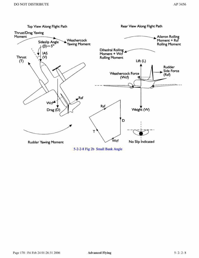
5-2-2-8 Fig 2b Small Bank Angle5-2-2-8 Fig 2b Small Bank Angle
DO NOT DISTRIBUTE AP 3456
Page 170 : Fri Feb 24 01:26:31 2006 Advanced Flying 5- 2- 2- 8

5-2-2-8 Fig 2c Rudder Fixed or Free5-2-2-8 Fig 2c Rudder Fixed or Free
DO NOT DISTRIBUTE AP 3456
Page 171 : Fri Feb 24 01:26:31 2006 Advanced Flying 5- 2- 2- 8

Advanced Flying
Chapter 9 - Instrument Flying
Introduction
1. With the advent of automatic landing systems and the continuing development of pilot-interpreted aids, the RAF has a trulyall-weather capability. Moreover, the increasing congestion in and around controlled air space means that a pilot must spend a gooddeal of time referring to instruments, flying controlled procedures and communicating with ground stations. Furthermore, whenflying at night, external visual references may be limited. Every pilot, therefore, should have sound basic skill in instrumentflying.
2. During visual flight emphasis is placed on attitude flying; however, no matter how well an attitude is maintained visually, at leastone instrument must be consulted before the attitude is known to be correct. If a correction is necessary the change is made againstthe visual horizon. During instrument flying the real horizon is no longer visible so an artificial horizon is used instead. Thus, thereis no basic change in technique: the artificial horizon is used instead of the real horizon and becomes the master instrument
3. This master instrument can be an artificial horizon (AH), attitude indicator (AI) or flight director. For ease of presentationthroughout this chapter this instrument will be referred to as the AI.
DO NOT DISTRIBUTE AP 3456
Page 172 : Fri Feb 24 01:26:31 2006 Advanced Flying 5- 2- 2- 9

4. The combination of attitude and power is fundamental to aircraft performance and determines IAS and the flight path, ie ifattitude is selected to give an IAS, as in a climb, power determines the flight path; similarly, if power is used to adjust the IAS, as instraight and level flight, then attitude determines the flight path. Thus, because aircraft performance is controlled by attitude andpower, the AI and the instruments indicating power and balance (ball) are called the control instruments.
5. The remainder of the flying instruments show what effect the power/attitude combination is having on the aircraft performance.They are known, therefore, as the performance instruments.
Power Control
6. Most instrument flying procedures are flown using recommended power settings given in Aircrew Manuals. When flyingmanoeuvres other than the controlled procedures, eg steep turns, the normal visual power settings should be used. To make theseselections promptly and accurately, without unduly disrupting the flight instrument scan, it is best to make an estimated throttlemovement before including the power gauge into the scan. After this initial change the power can be accurately adjusted duringsingle glances intermixed with the normal scan.
7. A useful method of measuring small power changes is to use some characteristic of the throttle lever or quadrant design againstwhich these small adjustments of the lever can be felt.
Attitude Control
8. To fly accurately, it is necessary to be able to change to and maintain the correct attitude. It is also necessary to know when andby how much a change should be made. The AI meets the first two requirements but cannot indicate when and by how much thechange should be; this information can only be obtained from the performance instruments. If they show that the desired flight path isnot being achieved, the power/attitude combination should be adjusted. Thus all changes are made on the AI, power gauge or theball. The results of a change appear on the performance instruments.
Scanning
9. To take in all the information shown by the instruments, they should be scanned methodically. An obvious method would be tolook at each instrument in turn in a clockwise or anti-clockwise direction. Although no instruments would be omitted from this scan,priority would be given to the master instrument or to the performance instruments important for any particular manoeuvre, eg thecompass or directional gyro on rolling out from a turn. The technique therefore is to scan radially out from the AI to the performanceinstruments and back to the AI. Furthermore, since the performance information required differs for each manoeuvre, the scan ismade selective. Thus each performance instrument will be interrogated according to its importance at any given moment. Thismethod, illustrated in Fig 1, is called the selective radial scan. Note that two performance instruments are never scanned insuccession; the route from one to another invariably goes through the master instrument.
NOTE:In all the figures in this chapter:
a. A solid arrow denotes a constant scan.
b. An outlined arrow denotes a less frequent scan ratio of 1: 3.
c. A pecked arrow denotes “as required”.
5-2-2-9 Fig 1 Selective Radial Scan
DO NOT DISTRIBUTE AP 3456
Page 173 : Fri Feb 24 01:26:31 2006 Advanced Flying 5- 2- 2- 9
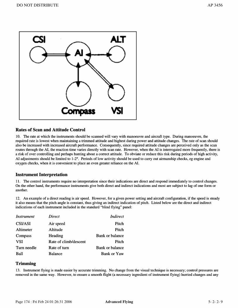
Rates of Scan and Attitude Control
10. The rate at which the instruments should be scanned will vary with manoeuvre and aircraft type. During manoeuvre, therequired rate is lowest when maintaining a trimmed attitude and highest during power and attitude changes. The rate of scan shouldalso be increased with increased aircraft performance. Consequently, since required attitude changes are perceived only as the scanroutes through the AI, the reaction time varies directly with scan rate. However, when the AI is interrogated more frequently, there isa risk of over controlling and perhaps hunting about a correct attitude. To obviate or reduce this risk during periods of high activity,AI adjustments should be limited to 1-2°. Periods of low activity should be used to carry out airmanship checks, eg engine andoxygen checks, when it is convenient to place an even greater reliance on the AI.
Instrument Interpretation
11. The control instruments require no interpretation since their indications are direct and respond immediately to control changes.On the other hand, the performance instruments give both direct and indirect indications and most are subject to lag of one form oranother.
12. An example of a direct reading is air speed. However, for a given power setting and aircraft configuration, if the speed is steadyit also means that the pitch angle is constant, thus giving an indirect indication of pitch. Listed below are the direct and indirectindications of each instrument included in the standard “blind flying” panel:
Instrument Direct Indirect
CSI/ASI Air speed Pitch
Altimeter Altitude Pitch
Compass Heading Bank or balance
VSI Rate of climb/descent Pitch
Turn needle Rate of turn Bank or balance
Ball Balance Bank or Yaw
Trimming
13. Instrument flying is made easier by accurate trimming. No change from the visual technique is necessary; control pressures areremoved in the same way. However, to ensure a smooth flight (a necessary ingredient of instrument flying) hurried changes and any
DO NOT DISTRIBUTE AP 3456
Page 174 : Fri Feb 24 01:26:31 2006 Advanced Flying 5- 2- 2- 9

temptation to fly on the trim should be avoided. The aircraft is properly trimmed when the appropriate attitude is maintained on theAI “hands-off”.
Balance
14. The only direct indication of aircraft in balance is shown by the ball, usually situated in the turn and slip indicator. The indirectindications can be a loss of air speed, bank or a changing heading if the wings are level. This is an unlikely situation during single jetoperation and is only likely to occur through gross mishandling. However, during propeller-driven and multi-engine operation it canbe a frequent occurrence particularly if the pilot becomes tense or resorts to a lazy scan by relying too much on one instrument.
15. During propeller-driven and multi-engine operation therefore, if the wings are known to be level, rudder should be used tomaintain a constant heading on the compass thus ensuring the aircraft is in balance. This is of particular importance during powerchanges which would otherwise cause yaw.
BASIC INSTRUMENT FLYING
General
16. The following explanations assume a knowledge of the visual flying techniques and procedures relevant to a particular aircraft.Once again, where attitude indicator (AI) is referred to in the text it is used as a generic term which includes artificial horizons.Similarly the combined speed indicator (CSI) includes both airspeed indicator and machmeter.
Straight and Level Flight
17. Straight and level flight during instrument flying is best thought of in terms of three separate actions: achieving, maintaining andcorrecting.
18. To Achieve Straight and Level Flight. To achieve straight and level flight, cruising power should be set, the straight and levelattitude should be selected on the AI and a coarse trim change made. If the attitude selected is correct, the altimeter and compass willbecome stationary. Any movement in the altimeter should be stopped by altering the AI pitch indication by a half or whole horizonbar width, the amount varying with aircraft type. If the compass is moving, ensure that the aircraft is in balance by noting thedirection of movement and applying a small bank correction to the AI even though it may be indicating wings level. A correction ofthis sort is only necessary when the AI is erected to a false vertical; normally it is not necessary. Thus straight and level flight isachieved using the AI, altimeter, compass and, on those aircraft prone to imbalance, an occasional glance at the ball (see Fig 2). Forthe sake of simplicity air speed is dealt with later.
5-2-2-9 Fig 2 Achieving Straight and Level Flight
DO NOT DISTRIBUTE AP 3456
Page 175 : Fri Feb 24 01:26:31 2006 Advanced Flying 5- 2- 2- 9
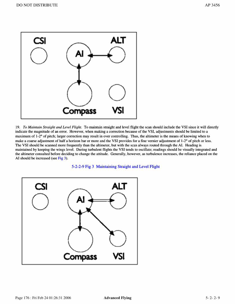
19. To Maintain Straight and Level Flight. To maintain straight and level flight the scan should include the VSI since it will directlyindicate the magnitude of an error. However, when making a correction because of the VSI, adjustments should be limited to amaximum of 1-2° of pitch; larger correction may result in over controlling. Thus, the altimeter is the means of knowing when tomake a coarse adjustment of half a horizon bar or more and the VSI provides for a fine vernier adjustment of 1-2° of pitch or less.The VSI should be scanned more frequently than the altimeter, but with the scan always routed through the AI. Heading ismaintained by keeping the wings level. During turbulent flights the VSI tends to oscillate; readings should be visually integrated andthe altimeter consulted before deciding to change the attitude. Generally, however, as turbulence increases, the reliance placed on theAI should be increased (see Fig 3).
5-2-2-9 Fig 3 Maintaining Straight and Level Flight
DO NOT DISTRIBUTE AP 3456
Page 176 : Fri Feb 24 01:26:31 2006 Advanced Flying 5- 2- 2- 9
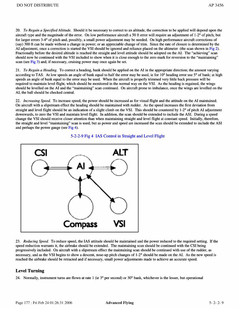
20. To Regain a Specified Altitude. Should it be necessary to correct to an altitude, the correction to be applied will depend upon theaircraft type and the magnitude of the error. On low performance aircraft a 50 ft error will require an adjustment of 1-2° of pitch, butfor larger errors 3-4° of pitch and, possibly, a small power adjustment may be needed. On high performance aircraft corrections of(say) 300 ft can be made without a change in power; or an appreciable change of trim. Since the rate of closure is determined by theAI adjustment, once a correction is started the VSI should be ignored and reliance placed on the altimeter (the scan shown in Fig 2).Fractionally before the desired altitude is reached the straight and level attitude should be adopted on the AI. The “achieving” scanshould now be continued with the VSI included to show when it is close enough to the zero mark for reversion to the “maintaining”scan (see Fig 3) and, if necessary, cruising power may once again be set.
21. To Regain a Heading. To correct a heading, bank should be applied on the AI in the appropriate direction; the amount varyingaccording to TAS. At low speeds an angle of bank equal to half the error may be used, ie for 10° heading error use 5° of bank; at highspeeds an angle of bank equal to the error may be used. When the aircraft is properly trimmed very little back pressure will berequired to maintain level flight, which should be monitored in the normal way on the VSI. As the heading is regained, the wingsshould be levelled on the AI and the “maintaining” scan continued. On aircraft prone to imbalance, once the wings are levelled on theAI, the ball should be checked central.
22. Increasing Speed. To increase speed, the power should be increased as for visual flight and the attitude on the AI maintained.On aircraft with a slipstream effect the heading should be maintained with rudder. As the speed increases the first deviation fromstraight and level flight should be an indication of a slight climb on the VSI. This should be countered by 1-2° of pitch AI adjustmentdownwards, to zero the VSI and maintain level flight. In addition, the scan should be extended to include the ASI. During a speedchange the VSI should receive closer attention than when maintaining straight and level flight at constant speed. Initially, therefore,the straight and level “maintaining” scan is used, but as power and speed are increased the scan should be extended to include the ASIand perhaps the power gauge (see Fig 4).
5-2-2-9 Fig 4 IAS Control in Straight and Level Flight
23. Reducing Speed. To reduce speed, the IAS attitude should be maintained and the power reduced to the required setting. If thespeed reduction warrants it, the airbrake should be extended. The maintaining scan should be continued with the CSI beingprogressively included. On aircraft with a slipstream effect the maintaining scan should be continued with use of the rudder, asnecessary, and as the VSI begins to show a descent, nose-up pitch changes of 1-2° should be made on the AI. As the new speed isreached the airbrake should be retracted and if necessary, small power adjustments made to achieve an accurate speed.
Level Turning
24. Normally, instrument turns are flown at rate 1 (ie 3° per second) or 30° bank, whichever is the lesser, but operational
DO NOT DISTRIBUTE AP 3456
Page 177 : Fri Feb 24 01:26:31 2006 Advanced Flying 5- 2- 2- 9

requirements may demand a higher rate. As a means of increasing proficiency, steep turns at 45° to 60° bank are practised. For shortturns, ie through an angle smaller than the angle of bank used for a rate 1 turn, the bank should be restricted to half the number ofdegrees of turn when flying at less than 100 kt; at speeds in excess of 100 kt bank equal to the amount of turn should be used.
Medium Level Turns
25. Entry. To enter a turn, bank is applied on the AI and the pitch indication is supported by cross checking the VSI to maintainlevel flight (see Fig 5).
5-2-2-9 Fig 5 Entering a Medium Level Turn
26. Maintaining. The AI is used to maintain both pitch and bank during turns. Bank is kept constant using the bank scale, and pitchusing the pitch scale. When using a mark of instrument not graduated in pitch, only experience can be used to assess the correctindication. The VSI and altimeter should be used to support the AI in the same manner in which they are used during straight andlevel flight. The technique for using the VSI is the same, applying small AI adjustments only. As the turn proceeds, the compass isprogressively included into the scan to monitor the roll-out heading (see Fig 6).
5-2-2-9 Fig 6 Maintaining a Medium Level Turn
DO NOT DISTRIBUTE AP 3456
Page 178 : Fri Feb 24 01:26:31 2006 Advanced Flying 5- 2- 2- 9

27. Roll-Out. To roll out on a heading, it should be anticipated by the amount normally used visually and the straight and levelattitude adopted on the AI, phasing the control movements to maintain level flight. If the speed is allowed to reduce during the turn, aslightly higher pitch attitude will be necessary for level flight until straight and level cruising speed is regained, but this is of smallaccount if the straight and level scan is started immediately.
Steep Turns
28. Entry. To enter a steep turn, bank should be applied on the AI with back pressure introduced to adopt a steep turn attitude.Power should be increased to maintain the entry air speed. The application of bank, back pressure and power should be completedsimultaneously (see Fig 7).
5-2-2-9 Fig 7 Entering a Steep Turn
DO NOT DISTRIBUTE AP 3456
Page 179 : Fri Feb 24 01:26:31 2006 Advanced Flying 5- 2- 2- 9

29. Maintaining. Whilst maintaining a steep turn, the scan is basically the same as that used during a medium level turn except thatit is extended to include the air speed indication. This is necessary to determine the amount of power required; therefore it should beincluded early. Judgement should determine throttle movements. The higher rate of turn makes it necessary to scan the compassmore frequently (see Fig 8).
5-2-2-9 Fig 8 Maintaining a Steep Turn
30. Roll-Out. To roll out from a steep turn, the heading should be anticipated by the amount used in visual flight. The roll-out ismade on the AI, and as the bank is reduced through 30° the power should also be reduced before being adjusted to the cruise settingas the straight and level attitude is resumed.
DO NOT DISTRIBUTE AP 3456
Page 180 : Fri Feb 24 01:26:31 2006 Advanced Flying 5- 2- 2- 9
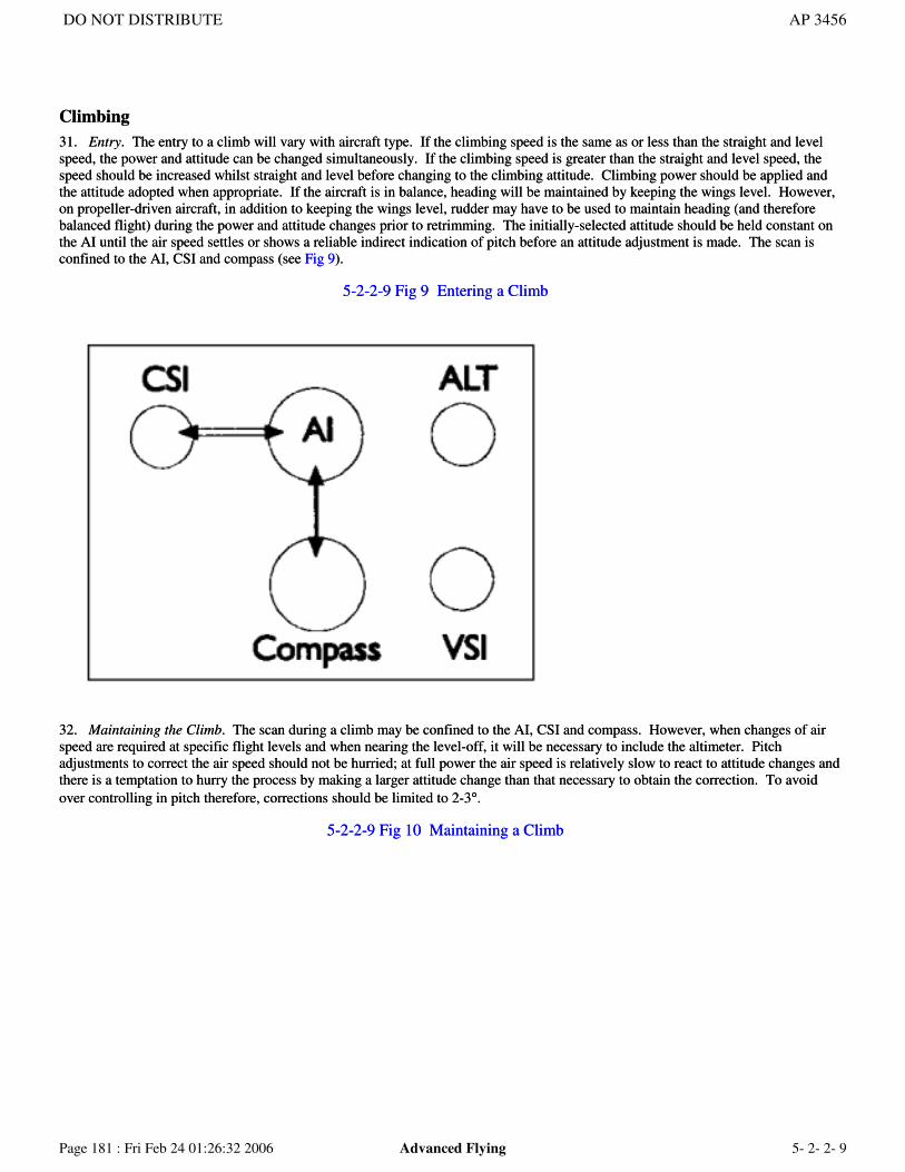
Climbing
31. Entry. The entry to a climb will vary with aircraft type. If the climbing speed is the same as or less than the straight and levelspeed, the power and attitude can be changed simultaneously. If the climbing speed is greater than the straight and level speed, thespeed should be increased whilst straight and level before changing to the climbing attitude. Climbing power should be applied andthe attitude adopted when appropriate. If the aircraft is in balance, heading will be maintained by keeping the wings level. However,on propeller-driven aircraft, in addition to keeping the wings level, rudder may have to be used to maintain heading (and thereforebalanced flight) during the power and attitude changes prior to retrimming. The initially-selected attitude should be held constant onthe AI until the air speed settles or shows a reliable indirect indication of pitch before an attitude adjustment is made. The scan isconfined to the AI, CSI and compass (see Fig 9).
5-2-2-9 Fig 9 Entering a Climb
32. Maintaining the Climb. The scan during a climb may be confined to the AI, CSI and compass. However, when changes of airspeed are required at specific flight levels and when nearing the level-off, it will be necessary to include the altimeter. Pitchadjustments to correct the air speed should not be hurried; at full power the air speed is relatively slow to react to attitude changes andthere is a temptation to hurry the process by making a larger attitude change than that necessary to obtain the correction. To avoidover controlling in pitch therefore, corrections should be limited to 2-3°.
5-2-2-9 Fig 10 Maintaining a Climb
DO NOT DISTRIBUTE AP 3456
Page 181 : Fri Feb 24 01:26:32 2006 Advanced Flying 5- 2- 2- 9
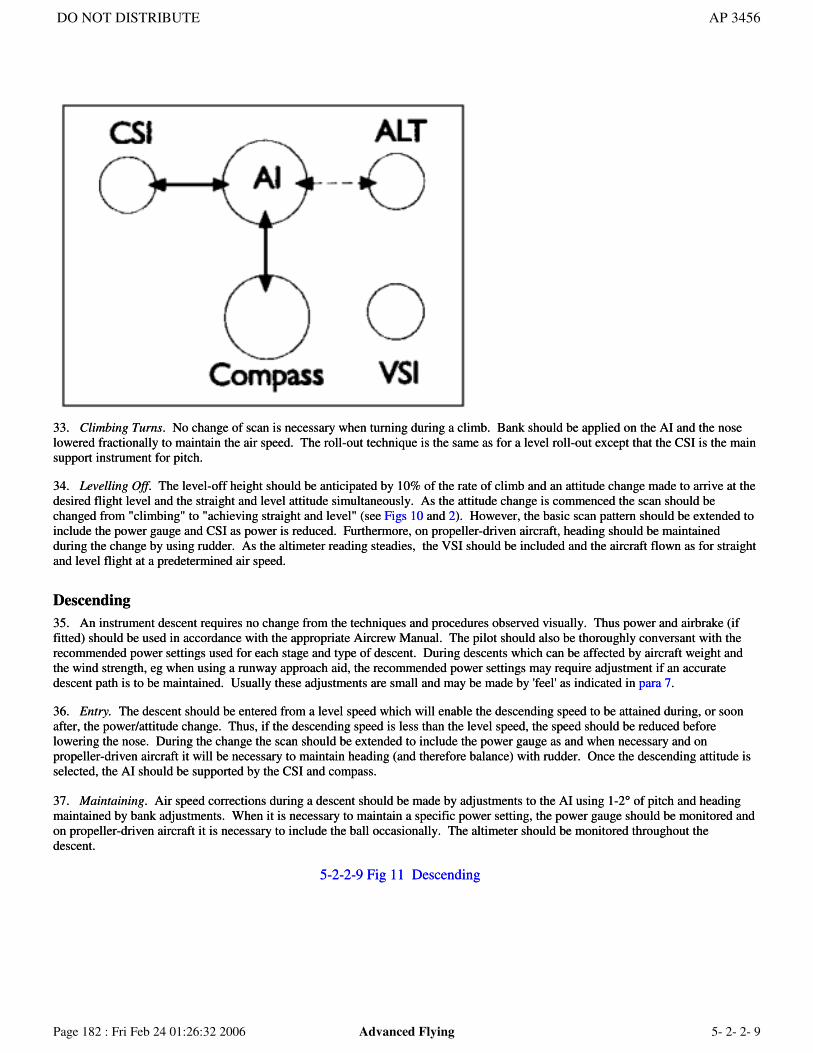
33. Climbing Turns. No change of scan is necessary when turning during a climb. Bank should be applied on the AI and the noselowered fractionally to maintain the air speed. The roll-out technique is the same as for a level roll-out except that the CSI is the mainsupport instrument for pitch.
34. Levelling Off. The level-off height should be anticipated by 10% of the rate of climb and an attitude change made to arrive at thedesired flight level and the straight and level attitude simultaneously. As the attitude change is commenced the scan should bechanged from "climbing" to "achieving straight and level" (see Figs 10 and 2). However, the basic scan pattern should be extended toinclude the power gauge and CSI as power is reduced. Furthermore, on propeller-driven aircraft, heading should be maintainedduring the change by using rudder. As the altimeter reading steadies, the VSI should be included and the aircraft flown as for straightand level flight at a predetermined air speed.
Descending
35. An instrument descent requires no change from the techniques and procedures observed visually. Thus power and airbrake (iffitted) should be used in accordance with the appropriate Aircrew Manual. The pilot should also be thoroughly conversant with therecommended power settings used for each stage and type of descent. During descents which can be affected by aircraft weight andthe wind strength, eg when using a runway approach aid, the recommended power settings may require adjustment if an accuratedescent path is to be maintained. Usually these adjustments are small and may be made by 'feel' as indicated in para 7.
36. Entry. The descent should be entered from a level speed which will enable the descending speed to be attained during, or soonafter, the power/attitude change. Thus, if the descending speed is less than the level speed, the speed should be reduced beforelowering the nose. During the change the scan should be extended to include the power gauge as and when necessary and onpropeller-driven aircraft it will be necessary to maintain heading (and therefore balance) with rudder. Once the descending attitude isselected, the AI should be supported by the CSI and compass.
37. Maintaining. Air speed corrections during a descent should be made by adjustments to the AI using 1-2° of pitch and headingmaintained by bank adjustments. When it is necessary to maintain a specific power setting, the power gauge should be monitored andon propeller-driven aircraft it is necessary to include the ball occasionally. The altimeter should be monitored throughout thedescent.
5-2-2-9 Fig 11 Descending
DO NOT DISTRIBUTE AP 3456
Page 182 : Fri Feb 24 01:26:32 2006 Advanced Flying 5- 2- 2- 9
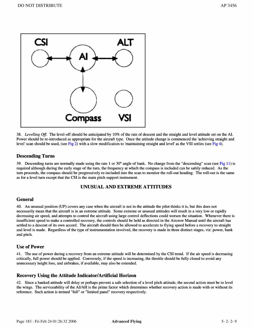
38. Levelling Off. The level-off should be anticipated by 10% of the rate of descent and the straight and level attitude set on the AI.Power should be re-introduced as appropriate for the aircraft type. Once the attitude change is commenced the 'achieving straight andlevel' scan should be used, (see Fig 2) with a slow modification to 'maintaining straight and level' as the VSI settles (see Fig 4).
Descending Turns
39. Descending turns are normally made using the rate 1 or 30° angle of bank. No change from the "descending" scan (see Fig 11) isrequired although during the early stage of the turn, the frequency at which the compass is included can be safely reduced. As theturn proceeds, the compass should be progressively re-included into the scan to monitor the roll-out heading. The roll-out is the sameas for a level turn except that the CSI is the main pitch support instrument.
UNUSUAL AND EXTREME ATTITUDES
General
40. An unusual position (UP) covers any case when the aircraft is not in the attitude the pilot thinks it is, but this does notnecessarily mean that the aircraft is in an extreme attitude. Some extreme or unusual attitudes will result in a very low or rapidlydecreasing air speed, and attempts to control the aircraft using large control deflections could worsen the situation. Whenever there isinsufficient speed to make a controlled recovery, the controls should be held as directed in the Aircrew Manual until the aircraft hassettled to a descent of its own accord. The aircraft should then be allowed to accelerate to flying speed before a recovery to straightand level is made. Regardless of the type of instrumentation involved, the recovery is made in three distinct stages, viz: power, bankand pitch.
Use of Power
41. The use of power during a recovery from an extreme attitude will be determined by the CSI trend. If the air speed is decreasingcritically, full power should be applied. Conversely, if the speed is increasing, the throttle should be fully closed to avoid anyunnecessary height loss, and airbrakes, if available, may also be extended.
Recovery Using the Attitude Indicator/Artificial Horizon
42. Since a banked attitude will delay or perhaps prevent a safe selection of a level pitch attitude, the second action must be to levelthe wings. The serviceability of the AI/AH is the prime factor which determines whether recovery action is made with or without itsreference. Such action is termed "full" or "limited panel" recovery respectively.
DO NOT DISTRIBUTE AP 3456
Page 183 : Fri Feb 24 01:26:32 2006 Advanced Flying 5- 2- 2- 9
43. AIs/AHs, are extremely reliable. Power failure is clearly indicated by the "OFF" flag warning, and the AI/AH can only betoppled with difficulty during manoeuvre. However, the toppled AI/AH may give a steady presentation, and it may only be possibleto detect this false indication by reference to the performance instruments.
44. If, prior to a UP, the flight path was known, eg distraction leading to disorientation during straight and level flight, climbs,descents and turns, it is beneficial to use full panel techniques using the AI/AH as the master attitude reference. However when theUP results from entering cloud from aerobatics, spinning, tail chasing, or from any situation where the serviceability of the AI/AH hasnot been checked for a longer period than normal, a limited panel recovery using the performance instruments is more suitable.
45. Full Panel Technique. Having confirmed that the AI/AH has not suffered power failure, with the horizon bar or pitch markingsin view, the aircraft should be rolled until wings are level. In extreme attitudes the horizon bar will still be readable, althoughpartially obscured by the instrument facing. Level flight is then obtained by pitching the aircraft so that the aircraft datum movestowards the horizon bar in the correct sense. Scanning of the performance instruments should be made to confirm the action takenand to regain balanced straight and level flight. If, having initiated full panel recovery, the performance instruments do not confirmthe AI/AH indications, or disorientation still remains, limited panel recovery should be implemented without further analysis.
46. Limited Panel Technique. With an unserviceable AI/AH, the turn needle is used as the master indication of bank to level thewings. However, before the turn needle can be relied upon, it is necessary to remove any g force which will cause it to over-readunduly. This g force should invariably be reduced using the body muscle sense as a yardstick, since to extend the scan to anaccelerometer might require a head movement and thus increase the risk of disorientation. On propeller-driven aircraft it will benecessary to reduce any extreme unbalance by centralizing the ball. However, time should not be wasted obtaining accurate balance;once any excessive g force has been removed and the aircraft is roughly in balance, a positive aileron movement should be made tocentre the turn needle. This corrective roll should be checked before the turn needle is actually centred, the amount of anticipationrequired varying with air speed and rate of roll.
47. Level Flight. The third stage of the recovery should be made using the information displayed on the altimeter - the onlyinstrument which indicates level flight accurately and almost instantaneously throughout the entire speed range. Positive elevatorshould be applied against altimeter movement, ensuring that the ailerons are kept neutral. The control deflection should bemaintained until the altimeter slows almost to a standstill, then a check movement made to hold a constant pitch attitude. The aircraftwill then be in an approximate straight and level attitude; the power can then be adjusted, and all the instruments interrogated toachieve accurate flight and to assess their serviceability, including re-erection of the AI/AH.
EMERGENCIES
General
48. In a military service, notwithstanding the high serviceability level encountered during training operations, in times of emergencyit may become an acceptable operational risk to set out on a mission with some instruments unserviceable. Moreover, battle damagemust always be regarded as a possibility-pilots must therefore be aware of the significance and action in the event of the loss of one ormore flight instruments.
49. As the current trend is to duplicate or even triplicate vital instruments and power supplies, a single instrument failure causes fewproblems. In the majority of cases an emergency will develop in stages beginning with an apparently insignificant malfunction whichonly becomes critical in unforeseen circumstances, or in the event of an additional emergency. Thus the loss of both primary andstandby flight instruments must be considered.
50. If, during manoeuvre, apparently ambiguous instruments indications are observed or the instruments do not respond correctly,the aircraft should be immediately recovered to straight and level flight and the cause investigated. Manoeuvres should not becontinued while attempting to analyse the trouble, since delay could bring about other complicating factors such as disorientation.The procedure for recovery will vary with aircraft type and the attitude obtained. If a master instrument is available for use and is notitself suspect, the straight and level attitude should be selected on that. If the master instrument is not considered reliable, the standbyAI can be used instead or, if no standby instruments are carried, then a recovery on performance instruments will be necessary.
Loss of Air Speed Indication
51. If all the air speed indications are lost at a safe height, the aircraft can still be effectively operated using the basic power/attitudeconcept provided an accurate air speed is not essential. Thus, by using the appropriate standard operating power settings and
DO NOT DISTRIBUTE AP 3456
Page 184 : Fri Feb 24 01:26:32 2006 Advanced Flying 5- 2- 2- 9

attitudes, straight and level, turning and climbing will create no difficulty. Similarly, descending would be safe at the higher speedsused during high rates of descent, but, as the aircraft approaches the ground and the speed is reduced, thereby reducing the safetymargin above the stall, the control problem becomes more critical. Consequently, the safest method of recovering to an airfield wouldbe to formate upon, or be shepherded by, another aircraft. When a join-up between aircraft is not practicable, the continued use of thepower/attitude concept down to break-off height may need to be considered as an alternative to abandoning the aircraft.
Loss of Heading Information
52. In the event of losing all visual and instrument heading information, D/F and radar facilities provide the only means of obtainingassistance. In these circumstances a ground controller's task is simplified if all turns are made at rate 1. On aircraft not fitted with aturn needle it is desirable that turns are executed at the calculated angle of bank for rate 1.
Loss of Direct Attitude Indication
53. The loss of all direct indications of attitude will vary in importance with the type of instrumentation. On aircraft fitted with thestandard basic instrument panel, the attitude can be deduced and controlled in all three planes without undue difficulty; in aircraftwith instrumentation which does not include a turn needle on which to control bank, control is possible only in pitch with the wingskept level on the compass.
Advanced Flying
Annex to Chapter 9 - Aircraft Icing
Introduction
1. It is important that all aircrew should be aware of the hazards of aircraft icing. The possibility of ice accretion on the airframe ofan aircraft should always be considered whenever ground temperatures are at 0 deg C or below, and whenever flights take placethrough cloud or rain at temperatures below 0 deg C (often referred to as the Freezing Level). Engine icing may occur even in clearair at temperatures above 0 deg C.
2. Frost, ice or snow on aircraft will adversely effect performance and even small amounts can have disastrous consequences.Accidents and incidents have been caused by:
a. Ice build-up on engine inlet pressure probes causing erroneous indications of engine power.
b. A thin layer of ice on control surfaces inducing flutter with subsequent structural damage.
c. Severe tailplane icing leading to loss of control when the flaps were selected down.
d. Very small deposits on wing leading edges dangerously eroding performance.
e. Attempting to take-off with wet snow on the wings and tail plane which had accumulated after earlier de-icing with dilutedfluid.
The problems of aircraft icing are not limited to in-flight conditions as many icing problems occur on the ground. Two physicalprocesses may cause a deposit of ice on objects exposed to the atmosphere. Ice may form directly from water vapour, that is bysublimation, or ice may form by the freezing of liquid water drops. At ground level these processes produce two familiar forms of icedeposit known as Hoar frost and Rime. Glazed ice may also form when raindrops freeze on striking cold surfaces.
Pre-flight Preparation
3. The whole aircraft should be free from deposits of frost, ice and snow. If a de-icing fluid has been used to remove any frost orice it should be remembered that the efficiency of the fluid under varying atmospheric conditions is dependent upon the correctmixture strength. For example, using fluid diluted with water will effectively remove ice; however, its ability to prevent further
DO NOT DISTRIBUTE AP 3456
Page 185 : Fri Feb 24 01:26:32 2006 Advanced Flying 5- 2- 2- 9A

formation will be significantly reduced. Under certain circumstances the fact that the aircraft surfaces have been wetted may actuallyenhance the accumulation of wet snow, particularly if there is any significant delay between de-icing and take-off. The temptation tobecome airborne because of any time control should be resisted if there is any doubt about the icing condition of the aircraft.
4. Particular attention should be paid to leading edges, control surfaces, flaps, slats and their associated mechanisms, hinges andgaps. All orifices and guards (eg generator cooling inlets, fuel vents, APU inlet, pressurization inlet and outlet valves, static plates)and exposed operating mechanisms such as nosewheel steering and oleos should be cleared of snow or slush, and de-iced when sorecommended. A wise precaution is to shake off all snow and ice from boots before entering an aircraft.
Start-up, Taxiing and Take-off Precautions
5. On some types of engine, the icing of probes can cause over-reading of power gauges. To prevent this possibility, and of damageto or flame-out of the engine, engine anti-icing should be switched on if the aircrew manual recommends it. If the OAT is less than10 deg C, and there is either precipitation, standing water, or the RVR is less than 1000 metres then a possibility of engine icing mustbe considered. Use of carburettor heat and propeller de-icing may be recommended.
6. Taxiing. During taxiing in icing conditions the use of reverse thrust on podded engines should be avoided, as this can result inice contamination on the wing leading edges, slats and flaps. For the same reason, a reasonable distance should be maintained fromaircraft taxiing ahead. In no circumstances should an attempt be made to de-ice an aircraft by placing it in the wake of the engineexhaust of another aircraft. It should always be remembered that stopping distances on snow and ice are increased. Painted areas areparticularly slippery, especially when covered with de-icing fluid or snow.
7. Take-off. Just before take-off a final check should be made to ensure that the wings are not contaminated by ice and snow, andthat fuel, propeller, airframe and engine icing controls are appropriately set as recommended in the Aircrew Manual. Take-off powershould be monitored closely, if possible against more than one instrument. Take-off direction should be selected by using the driestpart of the runway and pilots should be aware of their abort speed. Water and snow will seriously effect stopping distances and ifheavy rain has fallen pilots should be aware of the aircraft’s aquaplaning speed and its associated hazards.
In-flight Precautions
8. The build up of ice in flight, particularly in cloud and freezing rain, may be very rapid and aircrew should avoid icing conditionsfor which their aircraft are not approved. The various parts of the airframe are affected in different ways by ice formation, both withregard to the types of ice likely to form and with regard to the effect of ice accretion on their performance.
9. Aerodynamic Effects. When ice formation occurs on the leading edges of the aircraft wings and tailplane, the pattern of theairflow becomes modified round the affected part. This leads to an increase in drag, a decrease in lift, and perhaps to buffeting. Iceaccretion on the leading edges of the fin and rudder and other moveable parts may interfere with the airflow to such an extent thatcontrol is seriously affected. To appreciate how this accretion forms, consider an object moving through air which contains manywater droplets. As it moves it catches only a fraction of the water which is present in its path; this fraction varies with the shape ofthe object and is found to be greater for a thin wing than for a thick wing, other things being equal. It does not follow that a greatertotal weight of ice is collected by the thin wing, since the path swept out has a smaller cross-section. On the other hand, a smalldeposit on a thin wing may cause greater aerodynamic disturbance than a similar deposit on a thick wing. This dependence on shapeexplains why thin objects such as aerials, struts, the leading edges of propellers etc, are more likely to ice up than the more bluff partsof the airframe such as the blunt nose of the fuselage. The extremities of propeller blades have a much higher speed than other partsof aircraft and for this reason one might expect this component to be susceptible to icing, but there is some protection through kineticheating. The aerodynamic effects of ice accretion are of course not confined to disturbances at the leading edges; ice forming on otherparts of the wing or fuselage may lead to a considerable increase of drag. Ice formation under the wing may be particularly dangerousin that it is normally out of sight and its existence may be inferred only from a change in the performance of the aircraft.
10. Weight. The effect of an accumulated weight of ice will obviously reduce aircraft performance. An unequal distribution of icemay have serious effects, particularly when it occurs on a propeller, for with this component the lack of balance when parts of the icebreak away may lead to serious vibration. This type of hazard may also occur in connection with aerial masts, exposed balanceweights and control surface links, and may in extreme circumstances lead to fracture. It should also be remembered that an unevenincrease of weight through ice accumulation may alter the centre of gravity.
11. Effect on Instruments. Any small extension or orifice is liable to gather ice and if these include the pitot tube or static vents itwill reduce the efficiency of several instruments.
DO NOT DISTRIBUTE AP 3456
Page 186 : Fri Feb 24 01:26:32 2006 Advanced Flying 5- 2- 2- 9A
12. Effect on Control Surfaces. Normally there is a gap between the forward edge of a control surface and the fixed surface ahead ofit. In some positions of the controls sufficient ice may form in the gap to jam the control. The risk is greater on small aircraft than onlarger ones, since on the former the gap is smaller and the movable part thinner, leading to a greater rate of accumulation. However, itis dependent chiefly on the design of an aircraft rather than on its size.
13. Miscellaneous Effects. A well known effect is the formation of an ice coating on windscreens and canopies so that vision isrestricted. This is often due to hoar frost formation in clear air when there is a rapid change of temperature.
14. Communication. Ice and frost covering aerials can reduce their effectiveness, and vibration and an increase in weight coulddamage them.
Descending
15. If an aircraft has been operating for a long period at high altitude in cold conditions a rapid descent into warmer air temperaturesand the higher humidity at lower levels will cause frosting or misting up of the cockpit windows, and even the faces of instruments.Full use should be made of the defrosting and demisting devices fitted. It may also be necessary to allow time for the aircraft to warmup at lower altitude to disperse this misting before attempting to land. In addition, clear ice may occur when a rapid descent is made -the aircraft temperature lags behind the ambient air temperature and if rain is encountered whilst the temperature of the aircraft isbelow 0 deg C the relatively large drops form clear ice over a large part of the aircraft with considerable spreading over the wings.When the runway is covered with snow, ice or is slippery, a positive landing should be made, without drift on the centre-line. Do nottry and turn off the runway until the speed of the aircraft is suitably low. The friction of a wet runway will be greatly reduced from itsdry value depending on the degree of wetness and the type of surface. When the runway is wet braking distances can be significantlyincreased. Aquaplaning may occur when there is a layer of water on the landing surface and the tyre is no longer in contact with thesurface.
Airframe Icing Factors
16. Freezing of Supercooled Water Droplets. The most important factor for the build-up of ice on aircraft is the freezing ofsupercooled drops - either cloud particles or raindrops - following impact with a cold aircraft. A certain amount of heat is required tomelt a given mass of ice without a change in temperature and the same amount of heat is liberated when freezing takes place. This isknown as the latent heat of fusion and its value is approximately 80 calories per gramme of water or ice. Only 1/80th of a drop canfreeze for every degree Celsius by which the temperature is below 0 deg C. Once the temperature of the partly frozen drop is raised, itbegins to lose heat by evaporation and conduction to the object in contact with it, so that the remainder of the drop freezes moregradually while assuming the temperature of its surroundings. The higher the temperature of the supercooled drop, the smaller thefraction which will freeze instantly and the greater the amount of liquid which will freeze progressively.
17. Temperature of the Free Air . Spontaneous freezing of supercooled drops in the free atmosphere is determined partly by thetemperature and size of the drop and partly by other factors. As the temperature falls the larger drops are likely to freeze first, while atlower temperatures only the smallest drops will remain liquid until a temperature of minus 40 deg C. The higher the temperature of asupercooled drop, the greater the fraction of the drop which remains liquid. The liquid portion then starts to flow over the aircraftthus favouring the formation of clear ice. At lower temperatures there is a tendency towards the formation of rime ice concentratednear the leading edges.
18. Size of Supercooled Drops. The smallest supercooled drops tend to freeze immediately on striking a cold aircraft; the latent heatof fusion is quickly removed by the airflow and there is little or no spreading of the drop before freezing is complete. At the sametime air is enclosed between the particles, so that accretion takes the form of rime concentrated near the leading edge. On the otherhand, large drops are accompanied by spreading of water over the airframe while the latent heat is being dissipated, so that freezingtakes place more slowly and tends to be in the form of clear ice. Drops of moderate size can produce results intermediate betweenthese two.
19. Severity of Ice Accretion. The severity of icing is defined as the rate of accumulation of ice by weight per unit area per unit time.Among the meteorological factors determining this rate are the amount of liquid water present and the size of the droplets. Thesecharacteristics are not the same throughout a particular cloud, even at one level. A cloud containing both liquid water and ice crystalsmay have large patches where one or the other predominate and icing will tend to be severe when the temperature is not far below 0deg C. An analysis of reports on ice accretion shows a preponderance of occasions at temperatures above about minus 10 deg C andindicates that the frequency diminishes rapidly when the temperature falls below minus 20 deg C, although occasional icing has beenreported at temperatures below minus 40 deg C.
DO NOT DISTRIBUTE AP 3456
Page 187 : Fri Feb 24 01:26:32 2006 Advanced Flying 5- 2- 2- 9A

20. Supercooled Rain. Supercooled rain occurs beneath warm fronts and occlusions and occasionally beneath cold fronts. Whenpresent, there is necessarily a warmer layer above, in which the temperature exceeds 0 deg C. When flying beneath this type ofmeteorological condition the best procedure is to climb into the warmer layer of air. The belt of frontal cloud and rain should ifpossible be crossed at right angles so as to give the shortest traverse through the icing region. A particularly dangerous procedurewould be to fly parallel to the front in the freezing rain, since heavy accumulation of clear ice could form rapidly.
Engine Icing
21. Piston Engines. Considerable cooling in the carburettor of piston engines can occur when the OAT is above 0 deg C. Thiscooling is the result of two factors, one the evaporation of petrol from surfaces wet with petrol, the other from the acceleration of airthrough the carburettor, which causes a local reduction of pressure and results in adiabatic cooling. The combined effect can reducethe temperature of air by as much as 25 deg C. To counter carburettor icing, heat is applied to maintain the internal temperatureabove 0 deg C. The direct injection type of carburettor is rarely subject to icing.
22. Turboprop and Jet Engines. The intakes of turboprop and jet engines are subject to icing in the same way as the airframe whenflight is taking place in supercooled water droplets. The susceptible parts are the rim of the intake where the radius of curvature maybe small, any struts across the intake, and the vanes in the early stages of the compressor. Thereafter, temperatures are usually toohigh for icing to be a problem, although ice breaking away from the inlet may cause damage to the engine. Generally speaking,engine icing will be directly proportional to the rate of airflow through the engine and thus to the engine rpm - it is frequently foundthat the rate of icing may be reduced by decreasing the rpm. When a jet engine is operating at high rpm during flight at low speeds, aswhen taking off and landing, or whilst stationary, as in running up, the pressure within the intake is much less than the pressureoutside. The consequent adiabatic expansion in the intake causes a drop in temperature as much as 5 deg C. If the clear indrawn airis moist and the temperature is near 0 deg C, prolonged operation may result in condensation and ice formation when this would notoccur on the airframe. This effect may accentuate the icing which would normally be expected when the flight is in icing cloud, orwhen the aircraft is taking off or landing in freezing fog. Usually jet engines ice up in flight only under conditions which might beexpected to produce airframe icing. The intensities of icing on the airframe and in the engine may be different since the airframeicing rate depends on the airspeed, whilst engine icing depends on the rpm. At high speeds the engine tends to be supplied with moreair than it needs and there is a ram effect, whereas at lower speeds, below about 250 knots, air is sucked in. Because of the ram effectat higher speeds some of the air is deflected round the intake and the icing rate increases markedly with increases of airspeed above250 knots. At speeds where the air is sucked in (below 250 knots) the water concentration of the air entering the intake remainsvirtually the same as free air so that engine icing rates tend to be constant with decreasing speed, whereas the airframe is likely toshow a marked decrease of icing rate with decreasing speed.
Summary
23. Aircraft encounter a greater variety of icing conditions in flight than on the ground, resulting in a wider variety of ice deposit.Snow, Ice and Frost in all its forms produce a flight safety risk. Being aware of the physical process and conditions which produceairframe and engine icing will help to avoid the dangers associated with this phenomenon. A more detailed explanation of factorsaffecting icing of aircraft may be found in AP 3340, Chapter 8.
Advanced Flying
Chapter 10 - Night Flying
Definition
1. For the purpose of flying training and the recording of night flying time, "night" is defined as the time between the end of civiltwilight in the evening and the beginning of civil twilight in the morning. For the purpose of standardization of air traffic controlprocedures, "night" is defined in JSP318 as the time between half an hour after sunset to half an hour before sunrise, at surfacelevel.
Introduction
2. The ability to fly an aircraft as efficiently by night as by day is required of every Service pilot. By day, the aircraft is controlled
DO NOT DISTRIBUTE AP 3456
Page 188 : Fri Feb 24 01:26:32 2006 Advanced Flying 5- 2- 2- 10

mainly by reference to ground objects and the visual horizon, supplemented by certain flight instruments. In the absence of externalvisual references, all of the flight instruments are used. Similarly at night the aircraft is controlled by a combination of external andinstrument references, provided that the pattern and perspective of lights on the ground can be interpreted, and sufficient of the naturalhorizon is discernable. On a dark night, with no external lights visible on the ground, the problem is much the same as flying incloud. It follows, therefore, that accurate instrument flying is of paramount importance if night flying is to be carried out safely andefficiently. At the same time, it must be emphasized that, although night flying poses additional problems to a similar flight duringthe day, none of the demands upon the pilot is unusual. With a properly equipped aircraft and the benefit of good pre-flightpreparation, the average pilot should find night flying operations well within his capabilities.
Preparation for Night Flying
3. Knowledge of Control Layout. Before night flying is carried out, the crew must be thoroughly familiar with the location andfunction of all controls, cockpit and emergency lighting, crash exits and emergency equipment, so that the correct actions or selectionscan be carried out under subdued lighting conditions, or even in complete darkness.
4. Dark Adaptation. Before night flying, bright lights should be avoided whenever possible to allow the eyes to become adapted tothe darkness. Full dark adaptation takes about 30 minutes, but exposure to bright lighting can destroy it in less than a second. Darkadaptation and night vision is significantly affected by a reduction in oxygen level. It follows, therefore, that heavy smoking isdetrimental to night vision.
5. Flight Planning. Flight planning for a night sortie is similar in most respects to that for a day flight, but consideration should begiven to the following factors where applicable:
a. Preparation of maps, charts and logs for ease of reading under low levels of illumination. (Note that markings in red will beillegible under red lighting and some other colour should be used for marking in danger areas, power cables etc.)
b. Possible limited availability of navigational assistance outside airfield normal operating hours (eg V/UDF).
c. Limited visibility for identifying ground features.
d. Changing light patterns in urban areas, particularly after the extinction of domestic lighting late at night.
e. Position of moon (visibility reduced down-moon).
f. Changes in accuracy of navigational equipment due to movement of the ionospheric layers. This effect is particularly markedduring the dusk/dawn periods (see AP 3456 Vol 9, Part 2 Sect 2, Chap 1).
g. If the sortie is intended to employ astro-navigation, the possibility of upper cloud obscuring the sky.
h. Selection and identification of airfield identification beacons and marine lights.
6. Night Flying Briefing. All aircrew engaged on night flying duties should attend a briefing, or carry out self-briefing, to ensurethat they are familiar with the following:
a. Airfield layout, dispersal areas, taxi pattern and obstructions.
b. Airfield and approach lighting, and obstruction lighting.
c. Serviceability of navigational aids.
d. Availability of diversion airfields.
e. Forecast weather conditions for period and area of flight.
f. Night flying orders, including marshalling signals to be used and emergency procedures.
g. Standard lamp and pyrotechnic signals. (JSP 318)
DO NOT DISTRIBUTE AP 3456
Page 189 : Fri Feb 24 01:26:32 2006 Advanced Flying 5- 2- 2- 10

Pre-Flight Checks
7. Prior to night flying, all external and internal lighting should be checked in addition to the carrying out of normal day-timepre-flight checks. Warning and indicator light day/night screens or irises should be set to the required position to avoid undue glare inthe cockpit. A torch should be carried to assist with external checks, and to provide an emergency source of cockpit lighting.
Engine Starting and Taxiing
8. Engine Starting. The day-time engine starting procedures are supplemented at night by the use of the aircraft external lighting tosignal the intentions of the pilot to the groundcrew. On many aircraft servicing platforms (ASP) the level of illumination fromfloodlights is sufficient for the use of normal day-time signals but, to avoid any possibility or ambiguity or confusion, these signalsshould always be confirmed by the appropriate light signals as detailed in the unit Flying Order Book. The same principle should beobserved when an external intercommunications system is used between the pilot and groundcrew.
9. Taxiing. When ready to taxi, the appropriate light signal is given to the groundcrew who will remove the chocks and thencommence marshalling with illuminated batons (see JSP 318). If taxi lamps are used whilst being marshalled, care should be takennot to dazzle the marshaller and thus limit the assistance he can give the pilot. Before leaving the dispersal area, the cockpit lightingshould be adjusted if necessary to avoid glare or distracting reflections in the cockpit canopy. The judgement of speed and distance ismore difficult at night than in daytime due to the lack of visual cues. Care must be taken, therefore, to keep taxiing down to a safespeed. A good lookout must be kept for aircraft taxiing ahead, as the tail lights can be difficult to distinguish, particularly in theabsence of any anti-collision lighting. If the pilot is at any time in doubt about the taxiing clearance available, or suspects thepresence of obstructions, the aircraft should be stopped and full use made of landing lamps or hand-signalling lamps to illuminate thesuspect area.
Take-Off and Climb
10. Before take-off, the cockpit lighting level should be checked and adjusted to an acceptable minimum to reduce the contrastbetween internal and external references. When flying an unfamiliar aircraft at night, or when out of night flying practice, the aircraftshould be held momentarily on the runway while the pilot assesses the perspective of the runway lighting in order to assist in thejudgement of a subsequent correct landing attitude. Throughout the take-off run, and immediately after becoming airborne, thedirection and attitude of the aircraft should be judged by reference to the runway lighting. When clear of the ground, and beforeexternal visual references are lost, attention should be transferred to the flight instruments and the aircraft placed in a steady climb asin normal instrument flying technique. Once the aircraft has reached circuit height, external visual references may again be used, ifavailable, to supplement the instrument indications.
Engine Failure After Take-Off
11. For a multi-engine aircraft, loss of an engine at night is no different from a similar emergency during day-time from the point ofview of aircraft performance and emergency action to be taken. However, the fact that the aircraft may have to be flown entirely byinstruments imposes an additional burden on the pilot. The case of a single-engine aircraft is rather more serious, and, following anengine failure at low level, the recommended course of action will almost invariably be to abandon the aircraft if possible. Thispresents no problem on aircraft equipped with ejection seats, but the minimum height for successful abandonment without theassistance of an ejection seat will normally preclude any possibility of escape from the aircraft at or below normal circuit heights. Insuch circumstances, the pilot is faced with no alternative but to attempt a forced landing within some 30° of the aircraft's originalheading, aided only by the aircraft landing lights. The chances of success can be considerably enhanced by local knowledge of theterrain in the vicinity of the airfield, and its suitability or otherwise for forced landings. The location of suitable areas should beincluded in the night flying briefing where applicable.
Circuit Flying
12. The circuit pattern for night flying is normally the same as by day, except that local flying orders may require the aircraft to beclimbed straight ahead after take-off until reaching circuit height. With omnidirectional runway lighting, the circuit pattern presentsno problems, but with unidirectional lighting it may be advantageous to make use of the compass to assist in flying an accuratedownwind leg parallel to the runway. A careful listening watch should be kept on the R/T so that the movements and intentions ofother aircraft in the circuit are noted, and the circuit planned accordingly.
DO NOT DISTRIBUTE AP 3456
Page 190 : Fri Feb 24 01:26:32 2006 Advanced Flying 5- 2- 2- 10

Approaching to Land
13. The approach to land is judged by the changing perspective of the runway lighting. On most airfields the pilot is assisted injudging attitude and descent angle by lighting extending out along the approach path from the runway threshold, and also by PAPIs(see Pt 2, Sect 1, Chap 2).
Landing
14. Most large aircraft have landing lamps of sufficient intensity that the final round-out and touch-down can be judged largely bythe use of normal day-time visual cues. On aircraft not so equipped, or in the event of failure of the landing lamps, the landing phasemust be judged by looking well ahead and observing the changing perspective of the runway lighting. Peripheral vision plays animportant part in this judgement; for most pilots, the runway lighting, as observed by peripheral vision whilst looking straight ahead,appears to be up around the level of the shoulders or ears when the aircraft is about to touch down. As mentioned in para 10, thiseffect can best be observed while the aircraft is lined up on the runway prior to initial take-off. During the landing run, care should betaken to reduce speed progressively and, before turning off the runway, a positive check should be made to ensure that the speed iswithin acceptable taxiing limits.
Overshoot Procedure
15. The procedure for overshooting is the same at night as for a normal instrument overshoot, with the addition of extinguishing thelanding lamps, if used, to avoid the possibility of causing distracting reflection from any cloud or mist patches, and to avoid confusionto other aircraft.
Navigation at Night
16. Subject to the considerations discussed in para 5, night navigation is similar in most respects to navigation by day.
17. The amount of map reading that is possible at night depends largely upon the prevailing conditions. On a bright moon-lit night,almost as many major features may be seen as during the day. When there is no moon, or when flying under a complete cloud layer,it may be very difficult to see any ground features that are not illuminated. In conditions of haze or mist, visibility is better whenlooking into the moon than down-moon.
18. Coastlines and large water features such as navigable waterways and lakes can often be seen under all but the most adverseconditions, thus forming valuable pinpoints or position lines. Towns are easily visible whilst the street and domestic lighting is on,but it should be remembered that the majority of domestic lights are switched off for the latter part of the night. The apparent shapeand size of towns can therefore vary considerably with the time of night. Railways can usually be seen on bright nights and dualcarriageways and motorways can often be identified.
19. Flashing/occulting lights from lightships or lighthouses on the coast, and aerodrome identification beacons inland, can be seen atfairly long ranges and because they flash or occult in distinctive groups or in Morse code, give a positive position; civil airfieldbeacons flash in green and Service airfield beacons flash in red. Distances are deceptive at night and the correct estimation of rangefrom an identified feature requires practice.
20. The use of a red light to illuminate the map should be avoided; under this light all markings in red on the map may beunreadable. Accurate flying and timing becomes even more important at night than by day, because of the reduced number of featuresthat can be seen. Strict adherence to the flight plan is necessary if turning points cannot be seen or identified.
Night Emergencies
21. In addition to engine failure after take-off, the only other emergencies which pose additional problems at night are:
a. Failure of radio.
b. Total electrics failure.
In both these cases, assuming the absence of a stand-by radio, the emergency can only be communicated to ATC by rejoining thecircuit and flying the appropriate emergency pattern as detailed in the local Flying Order Book. Although the procedures may be
DO NOT DISTRIBUTE AP 3456
Page 191 : Fri Feb 24 01:26:32 2006 Advanced Flying 5- 2- 2- 10
subject to local amendment, those most widely used for these emergencies are for the aircraft to fly a circuit at 600 ft AGL, and, whenon the dead-side of the circuit, make an appropriate signal, as laid down in JSP 318 and the Flying Order Book.
Advanced Flying
Annex A to Chapter 10 - Surface Lighting
AERODROME LIGHTING
Aerodrome Identification Beacons
1. Aerodrome identification beacons are provided at all aerodromes having a regular night flying commitment. The beacons flashtwo-letter Morse characters, coloured red for Military aerodromes, green for Civil. The signal is visible throughout 360 degrees inazimuth and up to 80 degrees vertically. The identification codes are promulgated in RAF Flight Information Publications and UKAir Pilot.
Aerodrome Obstruction Lighting
2. Permanent airfield obstructions are lit at night, and by day in conditions of poor visibility by red two-lamp fittings.
3. Permanent aerodrome obstructions require either a red light at the highest point so as to be visible from any direction, or lightingat the highest point plus sufficient additional lights to show pilots of aircraft the general shape and extent of the obstructions whenthey are:
a. Flying on the normal line of approach to the nearest runway.
b. Taxiing on the taxiway adjacent to the obstructions.
4. Selection of the appropriate method of lighting is by reference to the 'projected length' of the obstruction parallel to the edge ofthe nearest landing strip. If the projected length is less than 23 m (75 ft), a single red light is sufficient. If the projected lengthexceeds 23 m (75 ft) the obstruction is given additional lights to show its outline both from the approach and from the adjacenttaxiway. Should the actual length of the obstruction exceed 90 m (300 ft), it is then suitably outlined with lights without regard to itsprojected length.
5. The lighting of all permanent aerodrome obstruction lights is controlled from ATC.
6. Lighting of Temporary Obstructions. All temporary aerodrome and approach obstructions are indicated by red marker lamps.The lamps are arranged to indicate the full dimensions of the obstructions, both horizontally and vertically. Red lights must be soplaced at airfield obstructions that they give taxiing aircraft and moving vehicles adequate distance to manoeuvre well clear of theobstruction. Vehicles regularly operating in aircraft movement areas carry flashing amber beacons. Emergency services, fire,ambulance etc, carry occulting blue lights.
7. Aerodrome Approach Obstruction Lights. Aerodrome approach obstructions are lit by red two-lamp fittings. The layout ofapproach obstruction lighting may be divided into two aspects: vertical lighting and horizontal lighting.
a. Vertical Lighting. All approach obstructions have a red light on top, visible from any direction. In addition, if theobstruction has a height of more than 150 ft above ground level, further lighting at intermediate levels is required (in closelybuilt-up areas the mean roof-top height is taken to be 'ground level'). The number of intermediate lighting levels is determined byallowing one light for every 45 m (150 ft) of the obstruction. The number of lighting levels so found is then equally spacedbetween the top light and ground level, the lighting at each level is so arranged that it can be seen from any direction, eg a squarefactory chimney would require four lights at each level while a round chimney might be marked quite adequately by three lightsat each level.
b. Horizontal Lighting
DO NOT DISTRIBUTE AP 3456
Page 192 : Fri Feb 24 01:26:32 2006 Advanced Flying 5- 2- 2- 10A

(1) When the horizontal dimensions of an approach obstruction exceed 90 m (300 ft), further lights are added, so that a piloton the approach can see the horizontal extent of the obstruction. For this purpose the horizontal obstruction lights are spacedfrom 45 to 90 m (150 to 300 ft) apart. Within this tolerance the number of horizontal lights is the minimum necessary to givean adequate impression of the obstruction from any direction.
(2) If the horizontal element of the obstruction is more than 45 m (150 ft) above ground level, the horizontal lighting layoutis repeated at vertical intervals, the number of levels determined as in 'a' above.
(3) If any light is shielded in any direction by an adjacent object, an additional light is placed on that object so as to preservethe desired lighting effect.
(4) All obstruction lights are visible from vertically above, down to ground level.
All permanent approach obstruction lighting is controlled from ATC. At non-runway aerodromes all approach obstructions are lit atnight. At runway aerodromes the switches are so arranged that each one controls the obstruction lighting at both ends of a particularrunway. Only the obstruction lights associated with the ends of the runway in use are displayed at any one time.
8. Aerodrome Circuit Obstruction Lights. The method of lighting aerodrome circuit obstructions is the same as that employed foraerodrome approach obstructions.
Approach Lighting
9. Purpose. The most critical stage of an instrument approach, whether at night or in poor visibility, is the transition frominstrument flight to visual flight immediately prior to touchdown. The aim of runway approach lighting is to provide the pilot withvisual external references during this transition, and for the remainder of the approach. The presentation of the lighting givesindications of the aircraft's alignment with the runway and, in most cases, the angle of approach, the aircraft's attitude in roll, and thesafe touchdown point. The correct approach angle can be maintained, both day and night, by reference to the Precision ApproachPath Indicators (PAPI) described in Pt 2, Sect 1, Chap 2.
10. Familiarity with Types. In order to obtain the maximum assistance from the approach lighting, the pilot must be familiar withthe type of system installed at his destination. Military aircraft may be required to make use of a wide variety of airfields, bothmilitary and civil, local and foreign, all employing different standards and types of lighting. Details of the pattern of approachlighting at any particular airfield can be found by consulting the appropriate planning documents. The diagrammatic presentationsgiven in the Terminal Approach Procedure Charts (TAPs) are particularly useful when planning a landing at an unfamiliar airfield atnight or in poor visibility.
11. Main Instrument Runway. Provided that terrain conditions permit, a centre-line and five cross-bar high intensity white approachsystem extending to 900 m (3000 ft) from the threshold, with a low-intensity red T superimposed, is installed at the end of the mainrunway intended for instrument approaches (see Fig 1). Where the installation of the full pattern is impracticable, an abbreviatedsystem is provided.
5-2-2-10A Fig 1 Approach Lighting
DO NOT DISTRIBUTE AP 3456
Page 193 : Fri Feb 24 01:26:32 2006 Advanced Flying 5- 2- 2- 10A
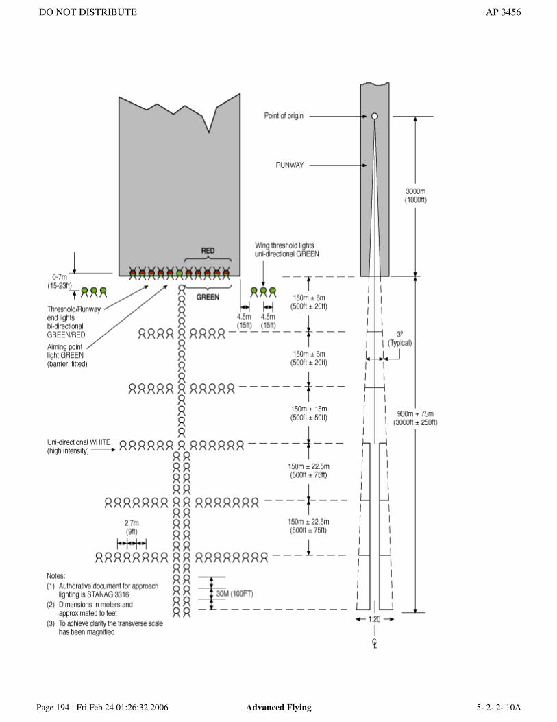
DO NOT DISTRIBUTE AP 3456
Page 194 : Fri Feb 24 01:26:32 2006 Advanced Flying 5- 2- 2- 10A

12. Main and Subsiduary Runways. For an approach at the opposite end of the Main Instrument Runway and on SubsidiaryRunways:
a. Approach lighting will be installed only where an operational need exists.
b. Where approach lighting is installed, the pattern will be similar to the main approach lighting.
c. The pattern will have a minimum length of 425 m (1,400 ft) and comprise at least one cross-bar.
Runway Lighting
13. Main Runways. Main runways are equipped with high-intensity unidirectional elevated edge-lights for both directions oflanding, and with omnidirectional elevated edge-lights operative for both directions of landing (see Fig 2).
5-2-2-10A Fig 2 Runway and Taxiway Lighting
DO NOT DISTRIBUTE AP 3456
Page 195 : Fri Feb 24 01:26:32 2006 Advanced Flying 5- 2- 2- 10A
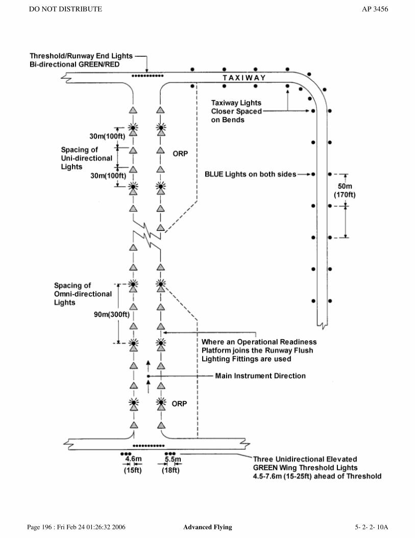
DO NOT DISTRIBUTE AP 3456
Page 196 : Fri Feb 24 01:26:32 2006 Advanced Flying 5- 2- 2- 10A
14. Subsidiary Runways. Subsidiary runways are equipped with omnidirectional elevated edge-lights if the administrative authorityconcerned is satisfied that there is a requirement for an officially maintained subsidiary runway which will be used for night flying. Inthe case of a Military Emergency Diversion Aerodrome at least one subsidiary runway is equipped to this standard.
15. Spacing of Runway Lighting. The nominal longitudinal spacing of runway lighting is:
a. Unidirectional 30 m (100 ft)
b. Omnidirectional 90 m (300 ft).
Threshold/Runway-end Lighting
16. All runways with a lighting installation have threshold and runway-end lights. Threshold lights show an aviation green colour inthe direction of the runway approach. Runway-end lights show an aviation red colour towards the direction of landing. Thresholdand runway-end lights are to provide adequate definition of the threshold and runway-end regardless of intensity setting.
17. The minimum requirement for main runways is ten threshold lights at each end to define clearly the commencement of thenormal landing area. The minimum requirement for main runways is eight runway-end lights at each end to define clearly thetermination of the normal landing area. When the threshold is at the runway-end, bi-directional fittings may be used as a combinationof threshold and runway-end lights.
18. Threshold lights may be supplemented by 'wing bars' consisting of three unidirectional elevated high-intensity green lights ateach side of the runway. (See Fig 1).
19. Where an arrester barrier is installed, the centre light of the runway-end lighting is fitted with a filter of a distinctive colour fromthe other end bar lights (eg green).
NOTE:At RN aerodromes, threshold and runway-end lights are in two bars of five closely spaced lights, one bar each side ofthe runway at right angles to the runway edge, extending 4.5 m (15 ft) inboard from the runway edge. The 'wing bars'either side are not fitted.
20. Lighting of Displaced Thresholds. Where the touchdown point is displaced from the runway end, it is delineated byunidirectional green lights in the approach direction and the displaced portion of the runway by high-intensity unidirectional rededge-lights which are installed and spaced in the same manner as the runway-edge lights (see Fig 3). Where suitable, the displacedportion of the runway may be used for take-off.
NOTE:In the reciprocal landing direction, the area beyond the displaced threshold (upwind) is deemed to be part of the runwayand accordingly is to show high intensity unidirectional white edge lights. The runway end is to be identified byuni-directional red lights.
Zone and Distance Markers
21. Caution-Zone Lights. These lights are provided at certain aerodromes to indicate the amount of runway remaining for eithertake-off or landing. They are located 700 m (2,400 ft) from the upwind end of the runway at right angles to the runway edge. Theyare aviation yellow in colour and extend 4.5 m (15 ft) inboard of the runway edge.
22. Illuminated Runway Distance Markers. Illuminated runway distance markers should be installed on all main runways asfollows:
a. The markers are placed on both sides of the main runway on a line parallel and normally equidistant to the centre line of therunway.
b. The unit of distance is 300 m (1,000 ft). The markers indicate the runway distance remaining in thousands of feet (the lastthree digits being omitted). Where the length of the runway is other than a multiple of 300 m (1,000 ft), then half the odd lengthis used at each end of the runway for computing the position of the markers.
DO NOT DISTRIBUTE AP 3456
Page 197 : Fri Feb 24 01:26:32 2006 Advanced Flying 5- 2- 2- 10A

c. The markers are numbered from the point of origin, increasing towards the beginning of the runway.
d. The colour of the numbers is white on a contrasting background.
Taxiway Lighting
23. Taxiway lighting facilities are governed by the width and purpose of the taxiway (main or access):
NOTE:At certain RN aerodromes, sections of the main taxiway are fitted with green centre-line lights in addition to normaledge lights.
a. Taxiways less than 18 m (60 ft) wide.
(1) Main routes are lit by aviation blue edge lights 50 m (170 ft) apart with closer spacing on bends.
b. Taxiways 18 m (60 ft) or more wide.
(1) These taxiways are lit by green centre-line lights only, spaced at a maximum of 30m (100 ft) apart, with close spacing onbends. The last four lights of the taxiways entering a runway are spaced 2 m (6 ft) apart.
(2) Warning of the entrance/exit to a hardstanding is given by a bar of five yellow taxiway lights known as a 'taxiway stubbar'. Stub bars are provided where aircraft have a choice of direction, one of which is a right angled turn giving direct accessto a hardstanding. Where entry to a hardstanding is via a secondary route then a stub bar is provided at the entrance/exit to thesecondary route. Where a hardstanding exit, or secondary route exit from a hardstanding, joins a main taxiway, the centre ofthe junction is indicated by a single yellow light to warn pilots of approaching soft ground.
c. Turning Areas. At aerodromes where turning facilities for aircraft are provided at the runway ends they are lit as follows:
(1) Taxiway Loops. These are lit in accordance with 'a' above.
(2) Turning Circles. These are lit with blue edge lighting.
24. Holding-Position Sign. An illuminated board containing a triangle of blue lights is sited at the holding position on either side ofthe runway, 23 m (75 ft) from the outer edge of the taxiway and visible only from the taxiway side. The switching for permanentlighting will depend on the type of lighting installed. In the case of Unit Control Systems, the lighting is slaved with the runwayselector. In the case of Modular Control Systems it is slaved with the runway threshold/end lights and end lights where separatelyfitted. Holding positions are further identified according to the type of taxiway lighting in use:
a. A taxiway lit by aviation blue lights, has two blue lights at right angles to the taxiway on its inside edge with relation to therunway.
b. A taxiway lit by green centre-line lights, has two green lights in the middle of the taxiway at right angles to the centreline.
25. Lighting of Hardstanding and Other Areas:
a. Hardstandings. Only the entrances to hardstandings are indicated by blue taxi lights.
b. Aircraft Servicing Platforms and Operational Readiness Platforms. Aircraft servicing and operational readiness platformsare outlined by blue taxi lights. To achieve uniformity and minimize the risk of taxiing and other accidents, the followinginstructions are observed in the illumination of aircraft servicing platforms and dispersals:
(1) Dispersal lighting fittings are not to infringe runway or taxiway criteria.
(2) Illumination is not to interfere with the aerodrome lighting system or lighting aid, either by intensity or siting.
DO NOT DISTRIBUTE AP 3456
Page 198 : Fri Feb 24 01:26:32 2006 Advanced Flying 5- 2- 2- 10A

(3) No pattern of lights is to give a false indication to a pilot on the ground or in the air.
(4) All lights are to be screened to prevent dazzle on the ground or in the air.
MISCELLANEOUS LIGHTING
Marine Lights
26. Marine lights are positioned at prominent points around a coastline, either on land or on light vessels, for the benefit of shipping.Because each light is coded by duration, grouping and colour, it can give valuable assistance in night visual navigation of aircraft. Aknowledge of the coding abbreviations used on aeronautical charts is required.
5-2-2-10A Fig 3 Runway Lighting - Displaced Threshold
DO NOT DISTRIBUTE AP 3456
Page 199 : Fri Feb 24 01:26:32 2006 Advanced Flying 5- 2- 2- 10A
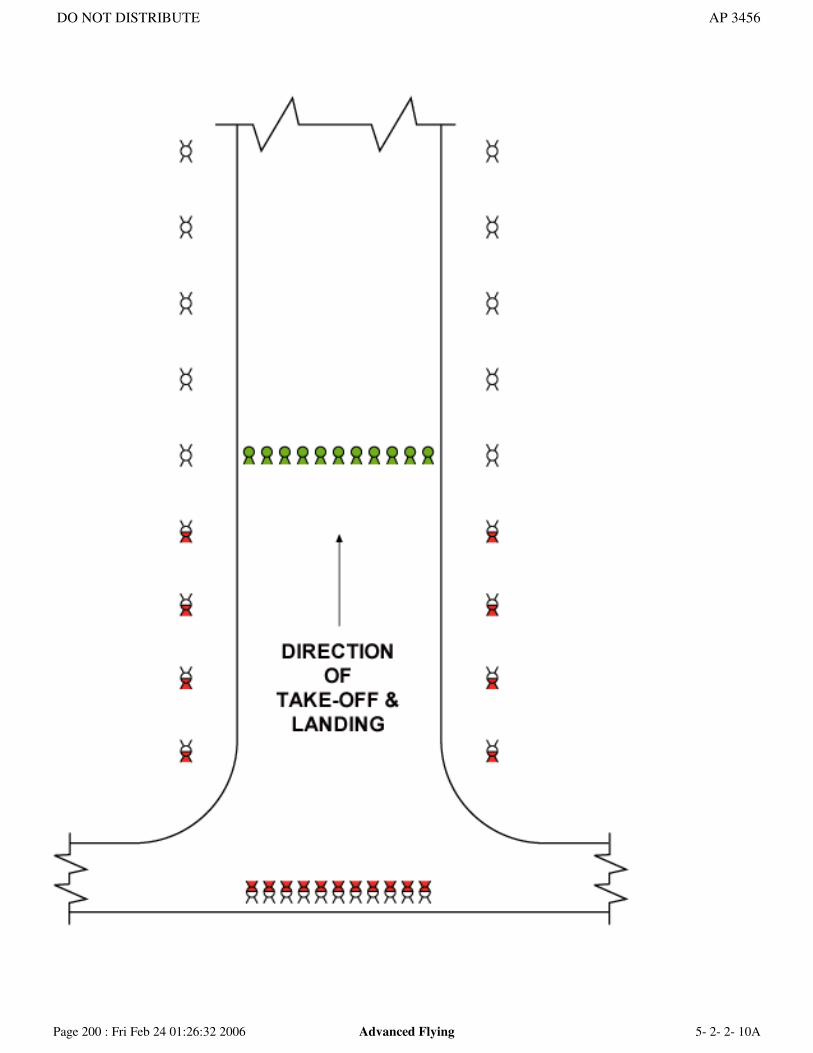
DO NOT DISTRIBUTE AP 3456
Page 200 : Fri Feb 24 01:26:32 2006 Advanced Flying 5- 2- 2- 10A
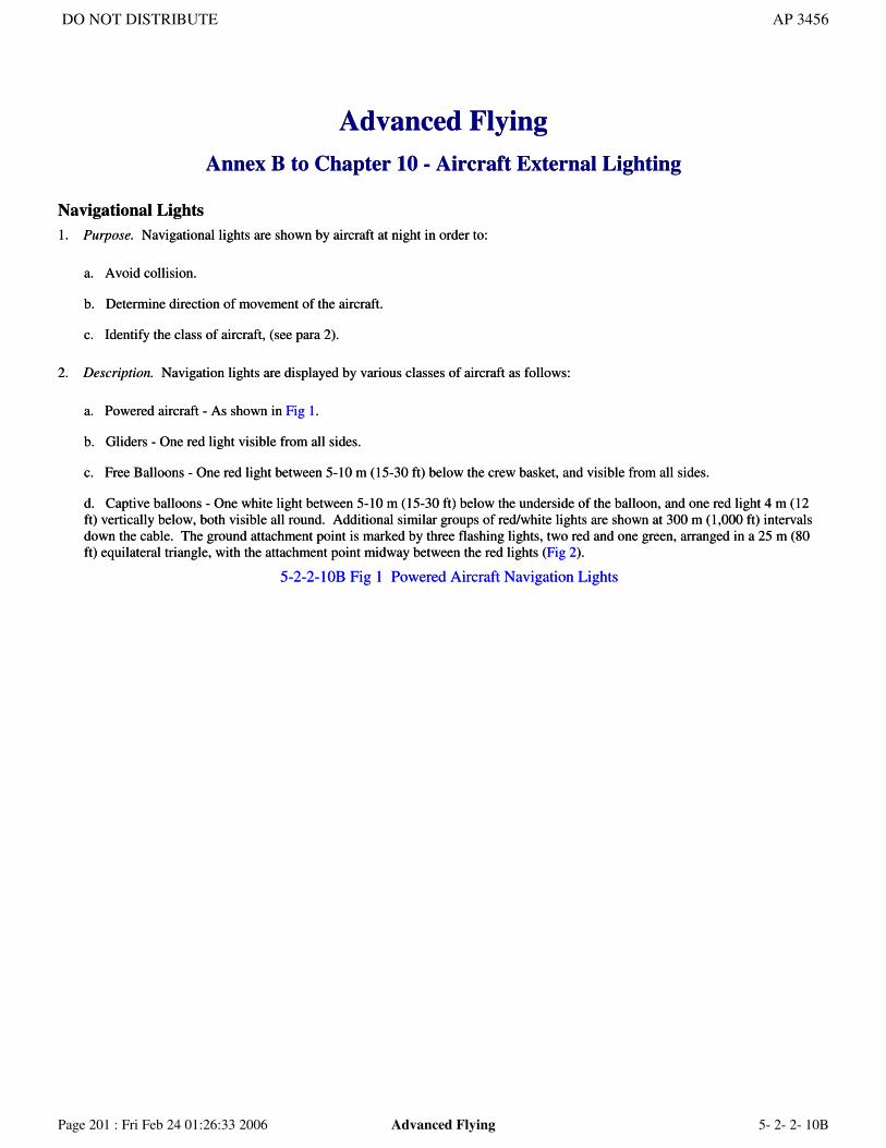
Advanced Flying
Annex B to Chapter 10 - Aircraft External Lighting
Navigational Lights
1. Purpose. Navigational lights are shown by aircraft at night in order to:
a. Avoid collision.
b. Determine direction of movement of the aircraft.
c. Identify the class of aircraft, (see para 2).
2. Description. Navigation lights are displayed by various classes of aircraft as follows:
a. Powered aircraft - As shown in Fig 1.
b. Gliders - One red light visible from all sides.
c. Free Balloons - One red light between 5-10 m (15-30 ft) below the crew basket, and visible from all sides.
d. Captive balloons - One white light between 5-10 m (15-30 ft) below the underside of the balloon, and one red light 4 m (12ft) vertically below, both visible all round. Additional similar groups of red/white lights are shown at 300 m (1,000 ft) intervalsdown the cable. The ground attachment point is marked by three flashing lights, two red and one green, arranged in a 25 m (80ft) equilateral triangle, with the attachment point midway between the red lights (Fig 2).
5-2-2-10B Fig 1 Powered Aircraft Navigation Lights
DO NOT DISTRIBUTE AP 3456
Page 201 : Fri Feb 24 01:26:33 2006 Advanced Flying 5- 2- 2- 10B

DO NOT DISTRIBUTE AP 3456
Page 202 : Fri Feb 24 01:26:33 2006 Advanced Flying 5- 2- 2- 10B

e. Airships - As for powered aircraft with the addition of a white nose light showing over a horizontal forward sector of 220°.
NOTE:Lights are only shown when the balloon is flown above 60 m (200 ft), or within 2 nm of an airfield or controlledairspace. In a designated danger area lights may not be shown at any height.
On aircraft where the arrangement of flying surfaces, etc precludes the placing of lights in the standard position, additional lights ofthe same colour may be used so that the required sector is covered.
5-2-2-10B Fig 2 Captive Balloon Lighting
DO NOT DISTRIBUTE AP 3456
Page 203 : Fri Feb 24 01:26:33 2006 Advanced Flying 5- 2- 2- 10B

DO NOT DISTRIBUTE AP 3456
Page 204 : Fri Feb 24 01:26:33 2006 Advanced Flying 5- 2- 2- 10B

3. Regulations. Navigation lights are to be displayed during the period of darkness by aircraft in flight, taxiing, being towed, andwhen being ground run, (JSP 318). Exceptions to this rule include aircraft participating in certain exercises, and also aircraft whichhave had a failure of navigation lights in flight, and have been authorized to continue the flight by the appropriate ATC unit.
Anti-collision Lights
4. Purpose. Anti-collision lighting increases the range at which visual contact can be made with an aircraft. The flashingcharacteristic of the lights make them easier to distinguish against a background of other lights or stars.
5. Description. The most common form of anti-collision lighting consists of a high intensity rotating red beacon which gives theappearance of 90 flashes per minute. The number of beacons used on an aircraft depends upon that aircraft’s size and configuration;the beacons are located so that at least one beacon is visible from any direction. A typical installation would have one beacon on theunderside of the fuselage near the nose, and another beacon on the rear top surface of the fuselage or on top of the tail fin. Someinstallations use a red strobe light in place of the rotating beacon. Civil practice now tends towards the use of white strobe lights atthe aircraft extremities in addition to the red anti-collision beacons. Some older installations have high intensity white anti-collisionlighting but, in most cases, this is now supplemented by the red beacon. Provision is made in some aircraft for the upperanti-collision lighting to be switched off independently; this avoids interference with the taking of astronomical observations.
6. Regulations. Anti-collision lights, when installed, should be used at all times during flights.
Taxi and Landing Lights
7. Aircraft may be equipped with separate or combined taxi and landing lights, and these may be remotely adjusted from thecockpit. Care should be taken to observe any limitations on use as detailed in the appropriate Aircrew Manual.
Miscellaneous External Lighting
8. Leading Edge Lights.Leading edge lights are installed on most passenger carrying aircraft, and provide a means of inspecting theleading edge of the wing in flight to assess ice accretion, or checking wing mounted engine installations. On propeller driven aircraft,it is common practice to use this lighting to illuminate the propeller disc while manoeuvring or when stationary on the ground.
9. Formation Lights. Formation lights assist in formation station keeping at night. Fixed wing tactical transport aircraft show acruciform display of white lights extending along the upper surface of the fuselage and wing. Some fighter aircraft display miniaturenavigation lights on the trailing edge of the wing tips. Helicopters which are required to fly in formation at night have rotor tip lightsto define the area of the rotor disc.
10. Flight Refuelling Lights. Flight refuelling lights include the FR tanker floodlighting, signal lighting, and drogue lighting, and thereceiver aircraft probe lighting (See Chapter 7).
11. Undercarriage Lights. Aircraft operated in the pilot training role and having a retractable undercarriage are equipped with anexternal undercarriage position indicator light which is illuminated whenever the undercarriage is locked down. On some installationsthe steady white light has been superseded by a flashing light.
12. Servicing Lights. A number of aircraft have built in servicing lights to assist with maintenance and servicing at night. Otheraircraft have portable servicing lights which can be connected to power sockets provided both inside and outside the aircraft.
Advanced Flying
Chapter 11 - Airways Flying Procedures
NOTE:All the charts appearing in this Chapter are for illustration only and must not be used for navigational purposes.
Introduction
DO NOT DISTRIBUTE AP 3456
Page 205 : Fri Feb 24 01:26:33 2006 Advanced Flying 5- 2- 2- 11

1. The Air Traffic Control (ATC) Services and establishment of controlled airspace has made it possible to sustain the all weatheroperation of civil and military air traffic. This chapter explains the divisions of airspace, the use of radio aids in proceduraloperations, departures from and arrivals at an airfield and flight in controlled airspace and traces the progress of a simple airwaysflight.
2. Division of the Airspace. Airspace is broadly defined as either uncontrolled or controlled. The UK has adopted the ICAOcategorization in which the airspace is subdivided into classes and functional areas. There are 7 classes (A-F). Controlled airspacecomprises classes A to E whilst classes F and G encompass uncontrolled airspace. The ICAO categorization is fully explained in JSP318A.
a. Controlled Airspace. The three main types of controlled airspace are control zones (generically abbreviated to CTZ but insome cases CTR), control areas (CTA) and airways; they are described as follows :
(1) Control Zone. A CTZ is established around an airfield, to protect all aircraft flying within it. A CTZ extends fromground level to a specific altitude.
(2) Control Area. Vast control areas exist as oceanic control areas (OCA). Many of those over land are classified asterminal control areas (generically abbreviated to TCA or in specific cases TMA). In all cases the lower limit is usuallydefined as an altitude, and the upper limit as an altitude or flight level. As CTAs and TCAs are complimentary to CTZs thelower limit of the former will usually be the upper limit of the latter.
(3) Airway/Area Navigation (RNAV) Route. An airway is a control area in the form of a corridor defined with reference toradio navigation aids. A basic RNAV route is an airway which is defined by WGS 84 coordinates which do not necessarilycoincide with radio navaids. All controlled airspace offers control to IFR traffic; IFR is mandatory at all times in most OCAs.Like the UK, many countries apply the mandatory IFR to most or all of their controlled airspace.
b. Uncontrolled Airspace. Uncontrolled airspace comprises Advisory Routes (ADR) along which an ATCC advisory radarservice is available and the remainder of the airspace which does not fall into any other controlled category.
3. Details of ICAO and national procedures appear in the RAF Flight Information Publication (FLIP) - Planning. Information onthe associated nav/comms equipments - ADF, VOR, ILS, DME, transponders, GPS and VHF/UHF communications is in AP 3456,Vol 4.
4. This chapter assumes a knowledge of the equipment appropriate to aircraft type, the various FLIPS, and the ability to flyaccurately on instruments. The chapter will not discuss flight planning in detail or the filing of flight plans (CA48/F2919).
Pre-flight Equipment Checks
5. It is normal practice to check flight instruments and nav/comms equipment before take-off in accordance with the relevantAircrew Manual.
6. Pre-take-off Selection of Aids. The appropriate communication and navigation aid frequencies should be selected before or at themarshalling point. Setting-up will vary with particular ATC procedural requirements or operating authority SOPs. In training, theILS frequency of the departure airfield is normally selected on NAV 2 and the first required VOR on NAV 1.
Pre-flight Clearance
7. A flight plan must be filed for any flight in controlled airspace, and a clearance must be obtained before joining. This clearanceis passed by RT; at large airfields a specific frequency may be set aside for this purpose, otherwise the ground control frequency maybe used. The tower frequency is only used at places where clearance requests are few.
8. Where the departure airfield is more than 10 minutes flying time from the airway joining point, clearance can be passed in the air.The departure instructions will include any pertinent flight limitations, transponder setting and the frequency on which to contact theairways controller. The initial call to the airways controller should be of the form “London airways this is ASCOT 3456. DepartedLyneham at 27 estimate Honiley at 38 climbing to flight level 160. Do you have my clearance?” If providing an ATCRU service, thecontroller can obtain this clearance on behalf of the captain.
DO NOT DISTRIBUTE AP 3456
Page 206 : Fri Feb 24 01:26:33 2006 Advanced Flying 5- 2- 2- 11

9. The clearance contains the following information in this order:
a. Aircraft callsign.
b. Clearance limit, ie the destination or some specified point en route.
c. Route and flight levels allocated, ie those available and not necessarily those requested on a flight plan or other flightnotification.
d. Any further information ie departure instructions, RT frequencies, transponder setting or expiry time of clearance.
10. The clearance must be logged and read back to ATC with the essential items verbatim. Shorthand notes, confirming oramending the pilots copy of F2919 provide a practical means of checking off the clearance as it is received.
Standard Instrument Departures
11. The larger and more busy airfields have specific outbound routeings for each runway; these help to keep RT to a minimum andto optimize the flow of air traffic. These routeings are known as standard instrument departures (SIDs). Many airfields are situated insensitive areas where it is essential to keep aircraft noise to a minimum. Noise abatement procedures are designed for this purpose;they may be contained in SIDs or in terminal approach procedure charts (TAPs). It is thus necessary to check both TAPs and SIDs toensure compliance with the procedures.
12. As it is possible to be given one of a number of SIDs when leaving an airfield on a particular route, it is essential to study allpossible relevant SIDs before flight. Some SIDs also demand specific rates of climb and IAS, so it may be necessary to check thatthese can be achieved by the particular aircraft being operated.
13. Southern departures from Gatwick are shown in the example SID chart at Fig 1.
5-2-2-11 Fig 1 Departure Chart - Gatwick
DO NOT DISTRIBUTE AP 3456
Page 207 : Fri Feb 24 01:26:33 2006 Advanced Flying 5- 2- 2- 11

DO NOT DISTRIBUTE AP 3456
Page 208 : Fri Feb 24 01:26:33 2006 Advanced Flying 5- 2- 2- 11

5-2-2-11 Fig 2 Departure Chart - RAF Brize Norton5-2-2-11 Fig 2 Departure Chart - RAF Brize Norton
DO NOT DISTRIBUTE AP 3456
Page 209 : Fri Feb 24 01:26:34 2006 Advanced Flying 5- 2- 2- 11
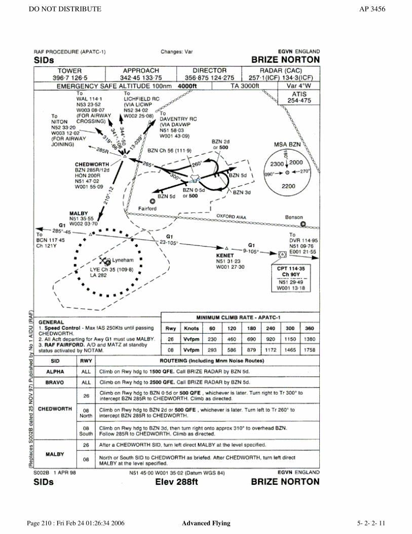
DO NOT DISTRIBUTE AP 3456
Page 210 : Fri Feb 24 01:26:34 2006 Advanced Flying 5- 2- 2- 11
The departure routes are the transition from airfield to the lower and upper airways and RNAV systems. The initial airway reportingpoint may be varied, within the limitations of the SIDs, to ease traffic congestion or possible delays. An example of a departure chartfor a military airfield (Brize Norton) is at Fig 2 for comparison.
14. SIDs for some European airfields are listed by departure runway; hence the SID required for a particular route will be found byfirst determining the runway in use and then choosing the SID appropriate to the departure direction. In North America however, thesequence is reversed - ie SIDs are listed for a particular departure direction and the procedure for each runway is then listed inturn.
15. Joining Airways. A standard instrument departure terminates with the aircraft established in the required airway. Where a SIDis not available an alternative joining procedure is required and it is important to remain clear of controlled airspace until clearancehas been received. The altimeter setting should be checked and the aircraft should be at the correct flight level. The transpondershould be set to Mode C well before the entry point. Approximately 2 minutes before the entry point the navigation aids should be setup for the first leg. At the joining point the aircraft should be turned onto the required heading, the time should be checked and, ifrequired, the controller should be advised.
EN ROUTE PROCEDURES AND TECHNIQUES
Procedures
16. Airways and upper air routes are normally 10 nml wide; centrelines usually delineated either by VOR radials, NDB bearings ormarker beacons. The lower limit of an airway may be either an altitude or a flight level and the upper limit is normally FL 245 withupper air routes continuing to FL 450. Except for RNAV routes a radio navigation aid is normally located where there is a change indirection. DMEs are frequently collocated with (or in close proximity to) VORs; significant points are sometimes marked by fanmarkers.
17. Position Reporting. It is essential that the controlling authority is a all times aware of the positions and flight levels of allaircraft using an airway. The increasing use of radar and transponders for identification of position and Mode C for flight levels hasallowed many countries to introduce negative position reporting. In negative position reporting the controller will acknowledge radarcontact and thereafter will call the aircraft only with changing information, eg frequency changes or new flight level etc. Wherenegative position reporting is not in use position reports must be passed to the controller at designated reporting points (marked by asolid triangle on en-route charts and normally associated with a VOR), the remainder being on request (marked by a hollow triangleon all en-route charts. A radio flight log (RAF Form 441H) should be used for flight planning and recording RT messages andposition reports. A position report (including transponder setting) should also be made when being handed from one controllingauthority to another.
18. Format. The format of the position report is:
a. The aircraft identification.
b. The aircraft position.
c. The time of the position.
d. The altitude or flight level.
e. The next position and its estimate.
f. The following position (required over certain countries, as identified in the FLIP Planning document).
The time should be passed in minutes unless this would result in ambiguity when hours and minutes GMT should be used.
19. Reporting. In addition to routine position reports, the aircraft may be required to confirm or report position including altitude orFL when there is a deviation from the flight plan, or when an alteration of clearance is requested. These circumstances may include:
a. Change in Flight Level. A request for change in flight level should include the aircraft identification, the new level requestedand the revised estimate at the next reporting point if applicable.
DO NOT DISTRIBUTE AP 3456
Page 211 : Fri Feb 24 01:26:34 2006 Advanced Flying 5- 2- 2- 11

b. Change in TAS. ATC should be advised if the average TAS varies by more than ±5% of that given in the flight plan.
c. Change in Estimates. ATC should be advised if the estimated elapsed time between reporting points changes by more than 3mins.
d. Track Error. It is sometimes necessary to deviate from track to avoid localized areas of bad weather. ATC should beinformed immediately, particularly if the deviation causes the aircraft to leave controlled airspace. The need for such a deviationshould be anticipated, and requested in good time.
e. Change in Route. Any request for a change in routeing should be made in the following form:
(1) Aircraft Identification.
(2) Type of flight plan (normally IFR).
(3) Description of new route, including flight levels and speeds commencing from the position/time that the change isrequested.
(4) Any other information eg new destination and alternate if the destination is changed.
f. Other In-flight Reports. The following reports should be made without being requested by ATC:
(1) The time and flight level on reaching a holding point or a point to which cleared.
(2) The time when leaving a holding point.
(3) When leaving one flight level on being assigned a different flight level.
(4) On reaching a new assigned flight level.
NOTE:Holding procedures will be considered later in this chapter.
Flying Techniques
20. The method used to track into and out of a beacon or waypoint will depend on the aircraft fit and the crew composition. Thebasic techniques however, are the same. To meet RNAV criteria an aircraft fit must give a Required Navigation Performance (RNP)standard of ±5 nm on 95% of occasions (known as RNP5) and is the minimum required to fly anywhere in Europe. However, theactual requirements for specific countries are listed in the FLIP Planning document. This may be met by a selection of the following:
a. Twin VHF RT.
b. GPS
c. VOR.
d. ADF.
e. DME.
f. INS or Inertial Reference System
g. 75 MHz Marker Beacon Receiver.
h. Transponder with 4096 codes on Mode A and Mode C capability.
21. General Tracking Procedure. On airways and RNAV routes an aircraft is required to approach and leave designated waypoints
DO NOT DISTRIBUTE AP 3456
Page 212 : Fri Feb 24 01:26:34 2006 Advanced Flying 5- 2- 2- 11

on specified radials - a procedure known as tracking. The sequence, to track either in or out, is:
a. Determine position relative to required radial.
b. Fly a heading towards radial (interception).
c. Determine the drift.
d. Fly a heading to maintain radial.
In carrying out the interception, any suitable angle may be used. Normally, it is only necessary to use the “double track error” methodto determine the interception angle, up to a maximum of 45°.
22. Tracking Out. Because an aircraft will normally commence tracking out close to or overhead the waypoint, an interception of upto 30° will be adequate in most cases.
23. Instrumentation. There will be a progressive mandate to carry instrumentation meeting RNP5 criteria as RNAV proceduresdevelop into TCA/TMAs and possibly into other areas of the lower airspace.
Timing
24. Apart from a clear GPS fix, there are a number of ways of checking flight progress and amending estimates between waypoints:
a. Dead Reckoning.
b. DME
c. Passing abeam of other VORs.
d. Marker beacons.
25. Dead Reckoning. The basic timing and flight progress is calculated at the flight planning stage. The estimates for significantpoints are not likely to be over 3 min in error for short legs; however, minor errors will be proportionally greater on longer legs; eg 2mins late on a 10 min leg - no amendment of estimate necessary, but a 20 min leg (in the same direction) would be 4 mins longer,therefore estimate revision would be necessary. The same technique over the flight as a whole may be used to amend the ETA at thedestination.
26. DME. DME is frequently collocated with VOR, providing a simple means of checking timing. As the equipment indicates slantrange, there will be an increasing error between plan and indicated ranges within 20 n miles of the overhead; one means of deriving acorrection is the graph at Fig 3.
5-2-2-11 Fig 3 Slant Range Graph
DO NOT DISTRIBUTE AP 3456
Page 213 : Fri Feb 24 01:26:34 2006 Advanced Flying 5- 2- 2- 11

27. Crossing A VOR Radial. Where DME is not collocated with VOR at a reporting point, crossing a radial from another VOR at ornear a right angle to track can provide an accurate timing check.
28. Marker Beacons. Marker beacons give an aural and visual indication of passing a significant point, the accuracy of thisindication decreasing with increase in height. Although most marker beacons are associated with ILS, some are situated alongairways; these are fan markers and provide range information. Note that the signal strength required to provide an aural indication isless than that needed to operate a light.
Alterations to Cleared Route
29. It may sometimes be necessary for ATC to change the clearance of an aircraft en route. This may be an actual re-routeing, orsimply a radar vector for separation followed by an instruction to resume normal navigation to the original reporting point. It is goodpractice to be aware of possible alternative routeings and to have any adjacent charts available which could be required.
30. When a re-routeing is given, the following should be carried out before reaching the starting point of the new section:
a. Write down the new clearance. Resolve any ambiguity (ie name or ident of a facility) and read the clearance back to ATC.
b. Transfer the route to the en route charts.
c. Mark appropriate facilities and RT frequencies.
DO NOT DISTRIBUTE AP 3456
Page 214 : Fri Feb 24 01:26:34 2006 Advanced Flying 5- 2- 2- 11

d. Resolve any difficulty in complying with the new route.
e. Calculate new headings, ETAs and safety altitudes.
TERMINAL PROCEDURES AND TECHNIQUES
The Hold
31. An aircraft may be required to hold at any point between departure and arrival; for convenience the hold is covered as a terminalprocedure. A holding point is normally a beacon, although it may be defined by a bearing and one or two specific DME ranges. Aninbound track and direction of turn is always specified - en route this will, with some exceptions, be inbound on the airway centrelineand all turns right; for terminal holds the track and direction of turn is given on the arrival chart, or the TAP, or both.
32. Joining, timing and turning procedures for the hold are given in the Flight Information Handbook. Note that the procedure statesthat due allowance is to be made in both heading and timing to compensate for the effects of known wind. The methods of applyingthose corrections are described in the following two paragraphs.
33. Corrections to Heading. As drift allowance cannot be applied during the turn, 3 times (2 times for a TACAN hold) the drift (upto a maximum of 30°) is allowed on the outbound leg. The bank may be varied (up to 25° or rate 1, whichever is the lesser bank)during the final part of the inbound turn to roll out on the desired track. Use the “clock analogy” (Vol 7, Pt 4, Sect 4, Chap 3) toestimate the wind effect.
34. Correction to Timing. It is necessary to know or estimate the head/tail wind component on the outbound leg in order to correctthe timing. Allow 1s per 2 knots (1.5 if above FL 140) of wind component; this should be added to the standard time for a headwind,or taken from the standard time for a tailwind. Note that timing starts abeam the beacon.
35. Departing the Hold. When clearance is received specifying the time of departure from the holding point the pattern should beadjusted within the limits of the established procedure in order to leave the holding point at the specified time.
Arrival Procedures
36. Many large airfields have published arrival procedures. Frequently these are the same airfields that have SIDs, and similarly,some arrivals include noise abatement procedures.
37. An example Standard Arrival (STAR) chart for Nice is shown in Fig 4. The holds at the various initial approach fixes (IAFs) areshown. From the appropriate IAF, depending on arrival direction, the aircraft may make a procedural instrument approach, be givenradar vectors to intercept the ILS or permitted to make a visual approach. At Nice the latter is closely defined by TAP chart to avoidbuilt-up areas.
Airfield Approaches
38. An airfield approach enables an aircraft to descend to a position from which it can land visually. In general, it is not aligned to aspecific runway so a circling approach may have to be carried out when visual. The normal types of airfield approach are:
a. ADF or VOR.
b. DF.
c. TACAN.
d. Radar (non-precision).
Procedures for a, b and c are published as Terminal Approach Procedure (TAP) charts. Where no RAF TAP exists, it will benecessary to select one from another source. The other main producers of TAPs are the USAF and the firms of Aerad (InternationalAeradio Ltd) and Jeppesen GmbH.
DO NOT DISTRIBUTE AP 3456
Page 215 : Fri Feb 24 01:26:34 2006 Advanced Flying 5- 2- 2- 11

39. Airfield Approach Techniques. The general techniques used are identical to tracking in and tracking out, as explained earlier inthis chapter, except that errors must be appreciated earlier and small corrections applied as the beacon is approached. Particularpoints are:
a. Initial descent may be given en route; further descent (down to minimum flight level or safety altitude) is given in theterminal hold. This procedure is known as shuttle in hold. The IAS should be reduced to approach/holding speed and the fieldapproach checks completed a few minutes before beacon overhead.
5-2-2-11 Fig 4 Standard Arrival - Nice
DO NOT DISTRIBUTE AP 3456
Page 216 : Fri Feb 24 01:26:34 2006 Advanced Flying 5- 2- 2- 11

b. The intermediate approach is commenced as the aircraft leaves the beacon and turns onto the outbound track. The stop watchshould be started as the beacon is passed to check progress outbound; when steady, a slow rate descent is carried out to theheight/altitude indicated on the TAP. It is normal to carry out the pre-landing checks at this stage.
c. The final approach is commenced either at the completion of the procedure or base turn, or a specified fix, or an interceptionof the final approach track. Note that the aircraft must not descend below the intermediate approach height/altitude until within5° of the specified inbound track or radial. The final approach is completed when the aircraft reaches a position from which avisual approach can be made or when a missed approach is commenced. On the final approach the aircraft is descended to
DO NOT DISTRIBUTE AP 3456
Page 217 : Fri Feb 24 01:26:34 2006 Advanced Flying 5- 2- 2- 11
minimum descent height (MDH) or circling approach minimum (CAM) as appropriate (see Flight Information Handbook).
40. The Procedure Turn. The procedure turn is a means of reversing direction whilst remaining on the same bearing. Whencommencing from overhead a beacon, it is used to leave the beacon on a specified track. The aircraft is normally turned 45° off trackto the right ± drift, and turns 225° the other way after 45°secs ± head or tail wind component. If turned only 30° off track then 60secs later a turn of 210° is made. The heading and time should add up to 90, ie 45° + 45 secs, 30° + 60 secs.
Runway Approaches
41. The standard runway approach aids are ground controlled approach (GCA) and instrument landing system (ILS). GCAprocedures are not published in TAPs as they are passed by RT. ILS procedures are published in TAPs, and an example of the Niceprocedure is given in Fig 5.
42. A common method of intercepting an ILS localizer is the reciprocal track procedure. In this, the aircraft is flown to a terminalbeacon and then outbound, descending to intermediate approach height en route to the outer marker. Having passed the outer marker,a (level) procedure turn is flown before establishing inbound. Descent is commenced when the glidepath is intercepted; this mayoccur before passing the outer marker.
43. If a hold is aligned with the ILS centreline, using a beacon as a holding fix, an alternate procedure is sometimes scheduled. Theoutbound leg is extended and the final approach is commenced on the inbound turn, when cleared.
44. Another type of localizer interception is from the terminal beacon situated approximately abeam the runway, about 10-20 n milesfrom the airfield, frequently with a locator beacon on the localizer centreline. This allows a straight in approach to be carried out.ILS is described in detail in Vol 4, Pt 2, Sect 2, Chap 2.
45. After landing, reference should be made to the Taxi chart, if published. An example is shown at Fig 6. The runway should bevacated as quickly as is safely possible. To cause a closely following airliner to go-around can be complicated and expensive to theoperator.
5-2-2-11 Fig 5 ILS for Runway 05R - Nice
DO NOT DISTRIBUTE AP 3456
Page 218 : Fri Feb 24 01:26:34 2006 Advanced Flying 5- 2- 2- 11

DO NOT DISTRIBUTE AP 3456
Page 219 : Fri Feb 24 01:26:34 2006 Advanced Flying 5- 2- 2- 11

5-2-2-11 Fig 6 Taxi Chart5-2-2-11 Fig 6 Taxi Chart
DO NOT DISTRIBUTE AP 3456
Page 220 : Fri Feb 24 01:26:34 2006 Advanced Flying 5- 2- 2- 11

DO NOT DISTRIBUTE AP 3456
Page 221 : Fri Feb 24 01:26:34 2006 Advanced Flying 5- 2- 2- 11

Advanced Flying
Chapter 12 - Airborne Early Warning (AEW) and Airborne Warning and Control
Systems (AWACS)
Introduction
1. History has proven that in warfare a side that can detect its enemy first has a distinct advantage. The detection method hasdeveloped from the use of hot air balloon observation platforms, through the advent of radar in the Second World War, and furtherimprovements with first IFF (identification, friend or foe) and subsequently SSR (secondary surveillance radar).
2. The need to bring all these technologies together in a system that overcomes the surface radar limitation of varying topographyand the curvature of the earth's surface resulted in Airborne Early Warning (AEW). The Boeing Sentry AEW Mk 1 or E-3D AWACS(Airborne Warning And Control System) incorporates a multi-mode pulse Doppler radar which provides a long range 'look-down'capability enabling the detection, tracking and identification of targets, particularly within the ground clutter. Additionally, a pulseradar detects maritime contacts out to the radar horizon and airborne contacts beyond the horizon. Housed in a Boeing 707-320Bairframe, the system provides real-time assessment of both enemy and friendly resources.
History
3. Post-war British AEW operations began with the Douglas Skyraider AEW Mk1, in use throughout the 1950's, and the FaireyGannet, between 1960-78, on the Royal Navy's aircraft carriers. The land-based AEW role was first assumed in 1972 by No 8 Sqn atRAF Lossiemouth equipped with the Shackleton AEW Mk 2 aircraft. Between 1951 and 1990, RN/RAF AEW operations reliedsolely on the AN/APS20 search radar. The Shackleton was intended as an interim measure until a replacement AEW aircraft wasdelivered. With the NATO countries unable to decide upon a common AEW procurement, the UK committed itself to the NimrodAEW Mk 3 in 1978 to meet the Air Staff Requirement (ASR) 400. The Nimrod AEW project was cancelled in 1986 with contractualand technical difficulties leading to repeated delays to the in-service date. The favoured alternative was the Boeing E-3 AWACSaircraft.
4. The first E-3D Sentry aircraft, of an order of 7, was delivered to the RAF on 26 March 1991. Final phasing out of the Shackletontook place on 1 July 1991, by which time 2 RAF crews had been trained at the NATO E-3A Component, in preparation for manningthe E-3D in the UK. All 7 Sentry aircraft were delivered by April 1992. The RAF became a formal contributor to, and fullparticipant in, the NATO Airborne Early Warning Force (NAEWF) on attaining Initial Operational Capability (IOC) on 1 July 1992.Full Operational Capability was declared on 31 December 1994.
Command and Control
5. The E-3D Component of the NAEWF has been involved in front-line NATO and UN operations since IOC. From 1 July 1992,the NAEWF consisted of 25 aircraft (18 E-3As and 7 E-3Ds) and 2 Components, with the UK E-3Ds representing a 25%contribution-in-kind: aircraft, aircrew and full support facilities.
6. Although UK-owned and under full command of Air Officer Commanding-in-Chief RAF Strike Command, the 7 E-3Ds areunder the day-to-day operational control of the NAEWF Commander. It therefore follows that the vast majority of flying tasksundertaken are NATO-assigned, in common with those carried out by the E-3A Component. Only a few national exercises ordeployments feature in the flying programme.
7. E-3Ds are either tasked through NAEWF Command or by national tasking agencies through HQ11/18 Gp. NAEW resources areallocated quarterly in advance and procedures for the use of AEW assets are laid down in the NAEW Employment Planning GuideVolume 1 (NC) and the NAEWF Manual 80-110-10 NAEW Tactical Employment (NC). Operational procedures exist to enable fullinteroperability and integration between various AWACS/AEW platforms; secure station handovers are achieved without break intasking or coverage.
MODE OF OPERATION
DO NOT DISTRIBUTE AP 3456
Page 222 : Fri Feb 24 01:26:34 2006 Advanced Flying 5- 2- 2- 12

Airframe Configuration
8. Figure 1 illustrates the UK AWACS configuration. The aircraft has a flight refuelling capability and seating for additional crewor passengers. This results in the possibility of flying sorties that extend beyond the permitted fatigue hours for a single flight crew.A pylon mounted rotodome above the rear fuselage houses the search radar and IFF antennae.
Crew Composition
9. The normal crew complement is 17. The flight crew comprises 2 Pilots, one of whom is always the Aircraft Captain (AC), oneNavigator and one Flight Engineer (FE). The mission crew comprises 13 operators responsible for the command, surveillance,control, communications and management functions to support the Sentry mission.
5-2-2-12 Fig 1 The E-3D Configuration
Flight Deck Crew and Tasks
10. The Flight Deck crew tasks are as follows:
a. Aircraft Captain (AC). The AC is nominated by the Sqn Cdr to be the Officer in overall command of the aircraft. The AC isresponsible for both the safety of the aircraft and for mission accomplishment.
b. Pilot. The Pilot is an individual qualified to fly the aircraft within his authorized limits.
DO NOT DISTRIBUTE AP 3456
Page 223 : Fri Feb 24 01:26:34 2006 Advanced Flying 5- 2- 2- 12
c. Navigator. The Navigator is responsible for the safe navigation of the aircraft at all times.
d. Flight Engineer (FE). The FE is responsible for managing the aircraft flight systems, including fuel, electrics, aircraftconditioning, cooling, engine monitoring and hydraulics.
Mission Crew and Tasks
11. Mission crew expertise derives from former ground environment personnel and aircrew with Air Defence, Ground Attack andMaritime backgrounds. The mission crew tasks are as follows:
a. Tactical Director (TD). The TD is responsible to the AC for mission accomplishment. The TD controls the mission crew,performing all applicable duties in support of the assigned task, including mission management and training.
b. Surveillance Team. The Surveillance Team is responsible for detection and tracking of airborne and surface objects within aspecified area of responsibility, and comprises:
(1) Surveillance Controller (SC). The SC manages the surveillance team and is responsible to the TD for the quality of thesensor surveillance functions, tracking, Electronic Countermeasures (ECM), Electronic Protective Measures (EPM),Electronic Support Measures (ESM), identification and voice/data exchange of participating units.
(2) Link Manager (LM). The LM is responsible to the SC for all aspects of data link operations in support of the surveillancetask
(3) Surveillance Operator (SO). The SO is responsible to the SC for the detection, tracking, identification and EPMfunctions in the assigned area and voice/data correlation with participating units.
(4) ESM Operator. The ESM, Passive Detection System (PDS), Operator is responsible to the SC for the operation andmanagement of the ESM System and for compilation of the EW Order of Battle.
c. Weapons Team. The Weapons Control Team is responsible for the employment and control of aircraft within the area ofresponsibility.
(1) Fighter Allocator (FA). The FA manages the weapons team and is responsible to the TD for the conduct of the air battleand control of assigned weapons systems (normally air defence and ground attack aircraft) in the area of responsibility.
(2) Weapons Controller (WC). The WCs are responsible to the FA for the control of assigned weapon systems includingauthorized engagements.
d. Communications Operator (CO). The CO is responsible to the TD for all communications requirements includingcryptographic material used in support of the mission.
e. Communications Technician (CT). The CT is responsible to the TD for the maintenance of all aircraft communications,cryptographic equipment and JTIDS equipment (see para 15).
f. Display Technician (DT). The DT is responsible to the TD for the operation and maintenance of the data processing system,data display system and on-board test monitor and maintenance.
g. Radar Technician (RT). The RT is responsible to the TD for the operation and maintenance of the surveillance radar and IFFsystems.
Roles and Positioning
12. The E-3D is able to detect, track and classify aircraft, missiles and surface vessels. By utilizing Air-to-Air Refuelling supportfrom RAF or NATO/USAF tankers, using the drogue/probe or boom/receptacle methods respectively, the E-3D may operate forperiods in excess of 12 hours. This can be at long range, conducting Offensive Counter-Air, Defensive Counter-Air,Anti-Surface-Force operations and other tasks in direct or associated support of ground and maritime forces. E-3s have the capabilityto control multiple interceptor packages, direct strike/attack aircraft, provide third-party targeting information for maritime units,
DO NOT DISTRIBUTE AP 3456
Page 224 : Fri Feb 24 01:26:34 2006 Advanced Flying 5- 2- 2- 12
provide Air Traffic Control and co-ordinate Combat Search and Rescue missions. The aircraft is positioned to provide coverage of anair surveillance volume extending to 300nm, from sea-level to the practical limit of combat aviation. E-3s are regarded as high valueair assets (HVAA); accordingly, when positioning AEW orbits, battle managers are obliged to consider the relative merits of earlydetection vis-á-vis the inherent risk from air and surface threats and the need for dedicated fighter support. Many factors affect anAEW aircraft's ability to carry out its assigned task and, therefore, once an area has been allocated or selected, orbit pattern andaltitude normally remain in the province of the TD.
OPERATIONAL SYSTEMS
Principal Sensors
13. The E-3D missions system comprises 3 major electro-magnetic sensors:
a. AN/APY-2 search radar.
b. Loral 1017 PDS.
c. AN/APX-103 IFF interrogator.
Other Mission Systems
14. Other systems used to promote mission accomplishment are:
a. Link 4.
b. Link 11.
c. Link 14/Radio Teletype.
d. Link 16 and IJMS (See para 15).
e. 4 HaveQuick 2-A UHF Radios.
f. SATCOM.
g. IBM 4pi CC2E computer.
Joint Tactical Information Distribution System (JTIDS)
15. JTIDS is a high speed, digital, UHF data link that provides secure, ECM-resistant communications amongst similarly equippedunits which are located within line-of-sight. JTIDS relay also enables data exchange beyond line-of-sight. The system architectureuses time division multiple access (TDMA) to provide access to a large number of units. Using the Class 2H Terminal, as installed inthe Sentry aircraft, JTIDS may be operated via both Link 16 and the Interim JTIDS Message Specification (IJMS). The use of Link16 by others such as other E-3Ds and E-3Fs, Tornado F-3s, USAF/USN aircraft and RN and USN maritime units provides increasedcapacity and versatility.
INTERNATIONAL CO-OPERATION
Other Contributors
16. The UK's contribution to the NAEWF has been described earlier in this chapter at para 4. E-3Ds are manned principally by RAFcrews, with some exchange personnel from the RN, USN, GAF and USAF. The NATO squadrons of the E-3A Component aremanned by integrated crews from Belgium, Canada, Denmark, Germany, Greece, Italy, The Netherlands, Norway, Portugal, Turkeyand the USA.
17. The French Air Force and the Royal Saudi Air Force (RSAF) also have the E-3 in their complements. The RSAF's fighter and
DO NOT DISTRIBUTE AP 3456
Page 225 : Fri Feb 24 01:26:34 2006 Advanced Flying 5- 2- 2- 12
E-3A elements are supported by KE-3A tankers, a number of which are reported to have electronic reconnaissance capabilities.
18. The USN operates E-2Cs with enhanced overland capability and the USAF Tactical Air Command (TAC) has a fleet of E-3 B/Caircraft deployed permanently to Alaska, Okinawa and, periodically, to Iceland. Also in their complement are E-8 JSTARS (see para19) aircraft jointly used by the USAF and the US Army.
19. Joint Surveillance and Target Attack Radar System (JSTARS). JSTARS is a long-range, air-to-ground surveillance and battlemanagement system with the ability of looking far behind hostile borders to detect ground movement. JSTARS detects, locates,tracks and identifies anything from a single vehicle up to many thousands of vehicles, even through intense ECM and clutter. Thesystem operates in all weathers, in real time and in constant communication with ground forces. JSTARS also maintainscommunication with command authorities through the JTIDS facility.
SUMMARY
20. AEW techniques have improved, as technology has advanced, to what we know today. The Boeing E-3 is favoured by manynations, as well as NATO, as a platform for their AEW components. Good crew co-operation, coupled with effective avionics andmission systems, makes the E-3 a formidable platform. The level of international co-operation seen in the AEW world, and supportfor the E-3, is expected to continue into the future, with the airframe alone expected to last 50 years.
Helicopter Flying
Chapter 1 - Helicopter Flying Techniques
Introduction
1. Control of the helicopter usually presents some difficulty to the experienced fixed-wing pilot during the early stages ofinstruction because of the new sensations associated with hovering, sideways and backwards flight, vertical climb and descent and theability to remain airborne at zero airspeed. However, this initial difficulty is soon overcome and unless restraint is exercised untilexperience is gained, overconfidence in the capabilities of both the aircraft and the pilot may be bred; the helicopter pilot shouldalways remember that although his aircraft is capable of a wide variety of tasks and can operate from places that are inaccessible toany other type of vehicle, he may be let down, figuratively and literally, with little warning and with surprising speed, if hemishandles the aircraft. If, on the other hand, the pilot is careful and uses the recommended flying techniques, the helicopter can beconfidently and safely flown to its limits.
BASIC TECHNIQUES
Ground Taxiing
2. The need to ground taxi a helicopter does not often arise but it may be desirable at times to move the aircraft from a parkedposition in order to take off safely, or to taxi it into a confined space. In conditions of very high or gusty wind it is usual to taxi theaircraft out from a hangar after engaging the rotor, or taxi it in before shutting down.
3. To ground taxi the helicopter the rotor rpm (Rrpm) for take-off must be available. The cyclic stick should be used to position thedisc approximately on the horizon, and the lever may be raised sufficiently to enhance forward movement of the aircraft; once theaircraft begins to move, the lever should be lowered to control the speed, which should never exceed a fast walking pace. If, afterlowering the lever fully, the speed is still too high, the position of the disc should be re-adjusted, but on no account should it be tiltedback beyond the horizontal position. If necessary, speed can be further reduced by the use of brakes. The same technique is used tostop the aircraft. Directional control is achieved by the normal use of yaw pedals but any turn should be of a wide radius and, whentaxiing cross-wind, the stick position should be adjusted to keep the disc laterally level.
4. Great care is necessary when taxiing over rough, or soft ground, or up a gradient because the power required to move forwardmay cause the aircraft to begin to lift off and if this occurs, the attempt must be abandoned. The helicopter must also be brought torest if severe lateral oscillation or fore-and-aft pitching develops. The latter is particularly dangerous and no attempt must be made tocorrect it with the cyclic stick, as this would involve tilting the rotor in the opposite sense to that of the fuselage, with a consequentdanger of the rotor striking the tail cone.
DO NOT DISTRIBUTE AP 3456
Page 226 : Fri Feb 24 01:26:35 2006 Helicopter Flying 5- 2- 3- 1

5. When ground taxiing, particular care should be taken when the danger of resonance exists. (See paras 42 to 44). A helicopterwhich is unserviceable to fly is also unfit to ground taxi.
Control in Hovering Flight
6. In forward flight the effects of the controls of the helicopter are very similar to those of fixed-wing aircraft, although their usemay differ slightly because of the addition of an extra control, the collective lever, which is used specifically to control height.However, at the hover the use of some of the controls changes slightly in order to compensate for this new mode of flying. Thehelicopter can be said to be hovering when the following three conditions of flight are fulfilled: constant position over the ground,constant height and constant heading, two of these conditions being controlled by a separate control in the cockpit.
a. Cyclic Stick. The position over the ground is controlled by the cyclic stick. Assuming a perfect hover, if the stick is movedthe rotor disc tilts, followed closely by the fuselage, both tilting in the same direction as the stick has been displaced. After aperceptible lag, the aircraft moves bodily over the ground in the same direction as the stick is moved. This lag between change ofattitude and movementover the ground is caused by aircraft inertia and if the pilot corrects the attitude during the lag, theaircraft's position will not alter. Aircraft attitude, controlled by the stick, is of prime importance when hovering.
b. Collective Lever. The height is controlled by the collective lever, working in the natural sense: raising the lever will increasethe height and vice versa.
c. Yaw Pedals. The yaw pedals vary the magnitude of the tail rotor force which is required to counteract the torque reaction ofthe main rotor. The pedals act in the natural sense: applying right pedal results in a yaw to the right and vice versa. In tandemrotor helicopters there is no need for a tail rotor as the two main rotors can be tilted in such a way as to produce the yawrequired.
d. In forward flight the yaw pedals provide balanced flight as in a fixed-wing aircraft. However, as there is no slip-stream effectin the hover, the stick cannot be used to turn the aircraft: its use would only result in bodily movement over the ground.
Effect of Wind on Control
7. When hovering in strong wind conditions the rotor disc will tend to flap-back from the wind and unless corrective action is takenthe helicopter will drift down-wind. To hover in a wind, therefore, the aircraft has, in effect, to fly into the wind at the wind speed.Thus, to maintain the hover, the pilot must tilt the disc into the wind, the amount of stick displacement from the central positionvarying with the wind strength. Cyclic and yaw control limits determine the maximum wind speed in which the helicopter can hovercross-wind or down-wind.
Effect of Wind on Power Required to Hover
8. As the disc must be tilted to maintain a hover in a wind, so the resultant airflow down through the disc is modified in such a waythat the mass flow is altered, thus enabling the hover to be sustained using less power. This effect is known as translational lift and isa very important factor in helicopter operation, especially at the lower end of the speed range. However, translational lift is notpresent when hovering in still-air conditions, but another factor, ground effect, becomes important.
Ground Effect
9. Hovering the helicopter near the ground in still-air conditions will require less power than is required at 50 or 100 ft. Thisphenomenon is known as ground effect. It is only present in still air, or very light winds, and its greatest effect will be when thehelicopter is at its lowest hover. The nature of the ground will have some bearing on the effectiveness of the ground cushion, eg asmooth surface produces most ground effect while a rough surface tends to minimize the effect.
Normal Take-off and Landing
10. It is normal practice to hover the helicopter immediately prior to landing and immediately after take-off. This enables the pilotto correct for any lateral motion before touching down and also allows him to check that the helicopter has been correctly loadedbefore committing the aircraft to forward flight. The hover height chosen will be a compromise between exploiting the maximum
DO NOT DISTRIBUTE AP 3456
Page 227 : Fri Feb 24 01:26:35 2006 Helicopter Flying 5- 2- 3- 1

ground effect, where less power is needed to hover, and the need to maintain a safe clearance between the aircraft and the ground forpossible manoeuvring.
11. Take-off. A take-off into the hover is accomplished by raising the collective lever and thus increasing the pitch on all the rotorblades. When the resulting increase in rotor thrust more than offsets the weight of the helicopter, the aircraft leaves the ground andclimbs vertically, the lever then being adjusted to maintain the desired hover height. During the take-off, the correct hovering attitudeis selected with the cyclic stick and any tendency to yaw, as torque is increased, is corrected by use of pedal. The stage when thelanding gear is in only light contact with the ground should not be prolonged - the aim being for a smooth unstick - as any lateralmovement at this stage could induce ground resonance.
12. Landing. Although a landing is basically a reversal of the take-off technique, the variations in helicopter design lead to slightdifferences. In general, the helicopter is first settled in a hover and then height is gently reduced by use of the lever. The aim is for afirm but smooth contact with the ground, with no movement except in the vertical plane. As soon as the landing gear is firmly incontact with the ground the whole weight of the helicopter is transferred to the ground with a smooth but firm downward movementof the lever, continuing the movement until the lever is fully down. Throughout the landing the hover attitude is maintained toprevent the helicopter from drifting; any tendency to yaw is checked by use of pedal. If manual throttle is used correct Rrpm must bemaintained until the lever is fully down in case a sudden take-off has to be made in the event of a mislanding.
Take-off and Landing out of Wind
13. Ideally, the take-off and landing should be made into wind, but there will be times when this is not possible. The basic landingand take-off techniques apply equally in cross-wind conditions, but in strong winds certain control limitations exist which must beanticipated and allowed for by the pilot.
14. During any out-of-wind take-off the tendency for the rotor disc to "flap-back" in relation to the wind must be checked by use ofthe cyclic control, otherwise the aircraft will drift sideways down-wind. On landing, this drift will be corrected by maintaining asteady hover prior to touchdown, but on take-off, the pilot must be prepared to incline the rotor disc slightly into wind by use of thecyclic control as the aircraft leaves the ground. In some helicopters the amount of rearwards cyclic control available is less than theamount of forward control. Loss of control can, therefore, occur whilst attempting to obtain a steady hover following a down-windtake-off, or when approaching the hover prior to a down-wind landing in a strong wind. In addition, during a down-wind take-off orlanding, the weathercock effect tends to make the aircraft directionally unstable.
15. Added to the drift problems associated with an out-of-wind take-off, landing or hover is the impairment of directional control.This becomes increasingly critical where a cross-wind tends to weathercock the aircraft in the same direction as the main rotor torquebecause, in the extreme case, the combined weathercock and torque effect will exceed the counteracting force which can be applied bythe appropriate yaw pedal. In such a condition, directional control could not be maintained.
16. When hovering cross-wind the attitude of the fuselage will be affected and on touching down the landing gear on one side of thefuselage will make contact with the ground before the other, resulting in a rolling moment of the fuselage as the landing is completed.The tendency for the disc to follow the fuselage must be prevented with the stick, the stick not being centralized until the collectivelever is in the fully down position. Tail rotor roll will also affect fuselage attitude. When the tail rotor is below the level of the mainrotor, as it normally will be in the hover, the tail rotor drift corrective force being produced by the main rotor will create a rollingcouple with the tail rotor thrust, causing the helicopter to hover one wheel or skid low.
17. Approach and landing down-wind should only be made when there is no alternative. Such a necessity implies an obstructedlanding area requiring a steep angle of approach at a low forward speed; in a strong tailwind this may mean that the helicopter has aneffective backward airspeed which is potentially dangerous because of impaired directional control and reduced aft cyclic control.Whenever there is a tailwind component, translational lift will be lost completely before the helicopter comes to the hover and duringthis period the rate of descent must be kept very low (less than 500 fpm in most helicopters. Consult Aircrew Manual for each type)to avoid encountering a vortex ring state (see paras 39 to 41). Before taking-off down-wind, the ground in front of the aircraft shouldbe examined to see that it is suitable for a run-on landing, which will be necessary if the rearward limits of the cyclic stick are reachedwhilst attempting to hover.
18. The limiting wind speeds for take-off and landing out of wind vary between types of helicopters. In some tandem rotorconfigurations, the take-off and landing is more easily accomplished in cross-wind conditions as this eliminates the rotor interferencewhich occurs when the aircraft is headed into wind.
DO NOT DISTRIBUTE AP 3456
Page 228 : Fri Feb 24 01:26:35 2006 Helicopter Flying 5- 2- 3- 1

Take-off and Landing on Sloping Ground
19. The degree of slope on which a complete landing, ie when the whole aircraft's weight is transferred to the undercarriage, may besafely made is not very great. Since the angle and direction of the gradient may be difficult to detect in a confined area, all landingson unfamiliar ground must be approached with caution. The technique is basically the same as that used for normal landing but greatcare must be taken to maintain a horizontal disc attitude and constant fuselage heading while transferring the aircraft's weight from therotor to the undercarriage.
20. As shown by Fig 1a, when landing across the slope, first contact with the ground is made by the up-slope landing gear. Transferof the weight to the down-slope landing gear must be made by continuing the downwards movement of the collective pitch lever, atthe same time preventing the rotor from following the fuselage movement by maintaining the rotor disc horizontal (see Fig 1b) withthe cyclic stick "held into the slope". This stage of the landing must be carried out carefully; if the cyclic control reaches its limitingstop before the whole of the landing gear is on the ground, the attempt must be abandoned, as beyond this point the aircraft will try toroll down the slope. (See Vol 1, Pt 2, Sect 1, Ch 5, paras 6-8). If the undercarriage has a castering tail wheel, the aircraft may tend toyaw down the slope during the landing. To assist in maintaining direction the wheel brakes and tail wheel locks should be appliedbefore attempting to land.
5-2-3-1 Fig 1 Landing on Sloping Ground
21. When the complete landing gear is on the ground the collective pitch lever must be lowered carefully but stopped if thehelicopter begins to slide down the slope. In this condition the helicopter is prone to ground resonance and must be lifted clear of theground immediately if this develops. Provided the lever can be fully lowered and cyclic limits have not been reached, the cyclic canbe relaxed to the central position but great care must be taken to ensure that this movement does not initiate a slide or yaw, in whichcase an immediate take-off may have to be made. It may be found impossible to reduce collective pitch completely but, with care,
DO NOT DISTRIBUTE AP 3456
Page 229 : Fri Feb 24 01:26:35 2006 Helicopter Flying 5- 2- 3- 1
passengers or freight can be transferred to or from the aircraft. If, during the take-off, the helicopter is allowed to pivot about itsup-slope skid or wheel there is a very real risk of dynamic rollover. If this condition seems possible the pilot should swiftly but gentlyreduce collective pitch; rapid lowering of the lever may lead to the helicopter bouncing off the downslope skid or wheel and rollingthe other way.
Sideways and Backwards Flight
22. For the purpose of manoeuvring in confined spaces, the helicopter can be flown sideways or backwards by simply moving thecyclic stick in the required direction. Because the airspeed in sideways and backwards flight is limited, the amount of translational liftobtained is also low, therefore relatively high power is required and these manoeuvres should normally be done at ground cushionheight.
23. In sideways flight the airflow acting on the tail cone causes a tendency to weathercock in the direction of flight and this must becorrected by use of yaw pedal. However, excessive speed in sideways flight may result in loss of directional control because theamount of yaw pedal required may be insufficient to counteract the weathercock effect.
24. In backwards flight directional control is difficult to maintain because of the tendency to weathercock. Additionally, asbackwards airspeed increases, the disc will flap-back relative to the airflow, but forward relative to the fuselage, and a furtherrearward movement of the stick will be required to maintain the original disc attitude. If the backwards airspeed is allowed toincrease to the point where it is necessary to have the stick fully back, any further flapping forward of the disc cannot be corrected andthe aircraft is likely to pitch forward out of the control. Care must be taken when stopping backwards flight, even at low speed, assmall corrective stick movements can cause large attitude changes and this may cause the rotor to strike the tail boom.
Turning on the Spot
25. A turn on the spot is a manoeuvre where the helicopter is yawed through 360° whilst hovering over a point on the ground andwhere a constant rate of yaw, constant Rrpm and height are maintained throughout.
26. In executing a spot turn, the rate of turn is controlled by the yaw pedals, position is maintained with the cyclic stick and heightwith the lever. In calm conditions, it should not be necessary for the cyclic stick to be moved from the normal hover position andthere should be very little displacement of the yaw pedals. In windy conditions, the cyclic stick will have to be moved throughout theturn to prevent any tendency to drift down-wind and the yaw pedals used to prevent any changes in the rate of turn due to the varyingweathercock effect. In the case where a turn is required in an aircraft's own length rather than about the main rotor axis, a certaincyclic stick displacement in the direction of the turn will be required. The length of the tail cone should always be remembered and agood look-out maintained in the opposite direction to the turn to ensure that no obstructions endanger the tail or main rotor. Thecentre of gravity of the aircraft should be checked before carrying out a spot turn to avoid the danger of reaching aft cyclic limitswhen hovering down-wind.
Transitions
27. The change from hovering to horizontal flight, or vice versa, is called a transition. To move from the hover into forward flightthe rotor disc is tilted forwards by a forward movement of the cyclic stick. As the speed starts to increase, the aircraft moves awayfrom the ground cushion, the height being maintained with the lever and, as forward speed further increases, translational lift is gainedand the aircraft starts to climb. During this acceleration forwards it will be necessary to move the stick forward to prevent the discfrom flapping back.
28. Transition to forward flight down-wind should be avoided if possible as the tendency to lose height is intensified by the loss oftranslational lift as the aircraft starts to move down-wind. Furthermore, the initial forward movement of cyclic must be very gentle asa harsh movement produces a large forward tilt to the disc which, with the wind behind the disc, results in severe nose-down pitchingand the possibility of reaching aft cyclic limits.
29. The transition from forward flight to the hover is initiated by a rearwards movement of the cyclic stick, adjusting the lever tomaintain height by a progressive increase in power. When forward flight ceases the aircraft must be levelled with cyclic to the hoverattitude to prevent the aircraft moving backwards. Further adjustment with the lever will be necessary as the ground cushion isre-established. During transitions, the torque will vary as the power is changed and any tendency for the aircraft to deviate from itsheading must be corrected with the yaw pedals.
DO NOT DISTRIBUTE AP 3456
Page 230 : Fri Feb 24 01:26:35 2006 Helicopter Flying 5- 2- 3- 1

Circuit Patterns
30. The flying characteristics of the helicopter may make the standard, fixed-wing circuit procedures unsuitable. Moreover, it isundesirable for the helicopter to conform to these procedures since they seriously reduce its natural flexibility of operation andpotential usefulness. Unless a special procedure is used, the helicopter, due to its low speed and small turning radius, is likely toconstitute a hazard and a distraction to fixed-wing pilots. It is, therefore, essential to have a circuit pattern which allows themaximum flexibility of operation and which, coincidentally, offers the minimum interference with fixed-wing aircraft.
31. When helicopters are operating from permanent bases which are also used by fixed-wing aircraft they should use the oppositecircuit direction to that of the fixed-wing aircraft. Since the helicopter circuit is then on the dead side of the fixed-wing circuit, andfixed-wing aircraft do not normally descend below 1,000 ft on this side, a safe separation of the two types is achieved. A portion ofthe airfield on the helicopter circuit side of the runway should be set aside as a helicopter manoeuvring area. If the runway in usemust be crossed, then it should be crossed at right angles over the centre of the runway.
32. When approaching an unfamiliar airfield the most convenient and accepted procedure is to remain outside the circuit area at aheight of not more than 500 ft until called in by the air traffic controller. If the runway in use has to be crossed, this should be done atright angles at the centre of the runway and the helicopter flown to the indicated landing position.
33. Where only helicopters are operating from the airfield and it is desired to fly a circuit as a precision exercise, the circuit patternshould be based on that shown at Fig 2.
MISHANDLING
Overpitching
34. Overpitching is the condition arising from the use of insufficient engine power to maintain Rrpm which are falling due to thehigh pitch angle and drag coefficient of the blades. If it is impossible to regain the Rrpm, then an overpitched state has been reachedand at this stage the only method of recovery is to reduce pitch. However this is not always feasible because a reduction in pitchmeans a reduction in height and, when hovering, loss of height may not be acceptable.
5-2-3-1 Fig 2 Basic Helicopter Circuit
DO NOT DISTRIBUTE AP 3456
Page 231 : Fri Feb 24 01:26:35 2006 Helicopter Flying 5- 2- 3- 1

Overtorqueing
35. The large increase in power available from turbine engine helicopters may make it possible to overstrain or "overtorque" thetransmission. Since torque = power/rpm, any increase in shaft power (sp), or decrease in Rrpm for the same sp will increase thetorque loading.
36. Overtorqueing can be avoided by monitoring the Torque gauge fitted to most helicopters.
37. The manufacturer can guard against overtorqueing by restricting fuel flow and, therefore, power, but only at sea level conditions.Because of the increasing efficiency of jet engines with height, power available increases with altitude and the need to controlaccurately the fuel flow within the laid down limits, to prevent overtorquing, cannot be over-emphasized.
38. The inherent danger in overtorquing is the possibility, in some turbine engine helicopters, of exceeding the fatigue life of atransmission component before its final overhaul life is complete. This can result, even if the aircraft is flown within its transient fuelflow and Rrpm limitations, and especially if the pilot does not observe the need to reduce the maximum torque with altitude. Thetorque limitation with height is designed to give a constant shp up to the aircraft's ceiling and any excursion past that limit willincrease the torque and, therefore, the transmission loading, beyond its limits.
Vortex Ring State
39. The vortex ring state occurs most commonly during a powered descent with a very low airspeed, although the rate of descent atwhich the effects become apparent will vary with aircraft type. The symptoms are normally pronounced juddering throughout the
DO NOT DISTRIBUTE AP 3456
Page 232 : Fri Feb 24 01:26:35 2006 Helicopter Flying 5- 2- 3- 1
airframe, a tendency for the aircraft to yaw, a slight variation in Rrpm, a rapidly increasing rate of descent which, if allowed tocontinue, can produce pitching and/or rolling, or, in perfect conditions, a smooth vertical descent at a very high rate.
40. The probability of vortex ring developing quickly with little warning is at its highest during the final stages of an approach toland; particularly if the approach has been made with a light tailwind, giving an acceptable groundspeed but a low, or zero, airspeed.It is, therefore, of vital importance that the pilot should check the local wind conditions before making an approach to land, andrestrict the rate of descent when the airspeed is low. Vortex ring may also be induced by applying power to recover from a zeroairspeed autorotation without first regaining forward speed or by allowing the aircraft to lose height in a steep nose-up attitude whenexecuting a quick stop.
41. As the vortex ring state develops only when the aircraft is descending in the direction of its own downwash, the corrective actionmust be to move the aircraft forward, by use of the cyclic stick, away from this flight condition. As soon as positive and increasingairspeed has been achieved, power should be applied to check the rate of descent, but the application of power when the airspeed isvery low will only aggravate the situation and prolong the subsequent recovery. It must be appreciated that, probably, there will be atime lag after the stick has been moved forward and before the aircraft gains forward airspeed and that during this period height willcontinue to be lost. It follows, therefore, that to allow the vortex ring state to develop when flying close to the ground would result ina condition from which it could be impossible to recover. When carrying out a vertical descent, or steep approach at zero or lowairspeed, the rate of descent should not be allowed to exceed 500 fpm. (See Vol 1, Pt 2, Sect 1, Ch 5, paras 9-15).
Ground Resonance
42. Ground resonance is the condition wherein there exists a severe sympathetic oscillation between the rotor system and theundercarriage of a helicopter. Any out-of-balance force set up in the rotors (by faulty blade damping, sideways motion on landing orwheel "bouncing") may give rise to ground resonance. During take-off an excessive time spent sharing support of the helicopter'sweight between the rotor and the undercarriage must be avoided and the aircraft must be lifted positively and cleanly off the ground assoon as it begins to feel "light"; for the same reason the collective pitch must be reduced smoothly and fully on touchdown. Thehelicopter is most prone to ground resonance during a running take-off or landing, whilst taxiing or when landing on sloping ground.
43. The corrective action to be taken if ground resonance occurs varies slightly according to the prevailing conditions but, basically,as the phenomenon results from contact with the ground, the aircraft should be lifted clear immediately. In some conditions, wherethe power setting is too low to lift the helicopter clear of the ground quickly enough, the collective lever should be lowered fully asquickly and smoothly as possible, the engine disengaged or stopped and the rotor brake applied - the intention being to change theRrpm by the quickest possible means available.
44. Ground resonance is a most dangerous condition. The likelihood of ground resonance occurring is eliminated as far as possiblein the design of the aircraft, but the conditions which can cause it should also be avoided (see Vol 1, Pt 2, Sect 1, Ch 5 for a detailedexplanation of ground resonance).
EMERGENCIES
Engine Failure
45. A free-wheel unit is fitted in the rotor drive system to allow the rotors to turn independently of the engine. If an engine failureoccurs during flight, the Rrpm fall rapidly if the original pitch is maintained and, in a single-engine helicopter, the aircraft will yaw inthe direction of the main rotor rotation. The collective pitch must be reduced immediately to the autorotative range to maintain rotorspeed and correction must be made for yaw.
46. In autorotation the aircraft descends at a steep angle but good control and manoeuvrability are retained. The aircraft can beautorotated to a suitable landing area within range, speed reduced prior to touchdown and the landing cushioned by use of lever,involving a reduction in Rrpm.
47. The best airspeed for autorotation, ie minimum rate of descent, usually approximates to the recommended climbing speed but,within certain limits, the angle of descent may be reduced and range increased by increasing the airspeed. Range may also beincreased still further by raising the collective lever and reducing the Rrpm to a specified minimum. Down to a certain limit, thisresults in increased blade efficiency and, therefore, reduced rate of descent, but it is important to regain Rrpm before landing.
48. Range may be reduced and angle of descent increased by reducing the airspeed, to zero if necessary, to give a near vertical
DO NOT DISTRIBUTE AP 3456
Page 233 : Fri Feb 24 01:26:35 2006 Helicopter Flying 5- 2- 3- 1

descent, depending on wind speed. At a high rate of descent, backwards airspeed should be avoided but in moderate wind conditionsthe aircraft can be allowed to drift backwards over the ground while still maintaining positive airspeed. Prior to landing, the rate ofdescent can be reduced and Rrpm increased by increasing the airspeed to normal. The change in attitude can be quite marked andbecause the height loss in regaining normal airspeed can be as much as 300 ft, a low speed autorotation should not be continuedbelow 700 ft AGL. It is essential to ensure that the aircraft does not land with backward groundspeed. When it is necessary to carryout an autorotation in conditions unfavourable to large attitude changes, eg at night or in bad visibility, the autorotation should becarried out at a low safe airspeed (approximately two-thirds the normal autorotation airspeed), except in aircraft with abnormally highrates of descent. With this type of autorotation, the attitude is held constant until close to ground level and the collective lever is usedto cushion the descent whilst accepting a groundspeed that may be high.
49. Approach and Flare-out. On approaching ground level following a normal or range autorotation, the forward speed must bereduced sufficiently to permit a safe touchdown. This is achieved by flaring (a positive rearward inclination of the rotor andfuselage), which also has the effect of increasing Rrpm and, reducing the rate of descent. The aircraft is then returned to a levelattitude at a low or zero groundspeed and the collective lever raised to check the descent completely just before touchdown. On somehelicopters it may be necessary to raise the lever slightly immediately after the flare and before the aircraft is levelled.
50. Touchdown Technique. On touchdown the Rrpm will be low and the coning angle high and, therefore, the lever should belowered smoothly so as to avoid the blades flexing and flapping down excessively. Rapid lowering of the lever must be avoided; thisapplies particularly to helicopters with a skid-type undercarriage since lowering the lever violently whilst still moving forward overthe ground will cause the aircraft to stop abruptly, possibly causing strain to the rotor mast bearing.
51. Speed Control. Under true forced landing conditions the aim should be to touch down with zero forward airspeed. However, ona good surface, a touchdown speed of up to 15 kt may be accepted with safety, provided the aircraft is kept level and landed withoutdrift. Because of the high rate of descent in vertical autorotation and the difficulty in judging the final hold-off, forward speed shouldbe reduced at as low a height as safely possible. It is also important that the flared attitude should be restored to a level attitude ingood time before touchdown because once the lever is raised, the Rrpm fall and this causes a progressive loss of stick control and anincreased tendency to yaw as tail rotor rpm fall. Incorrect attitudes or headings cannot easily be rectified at this stage and landingwith drift may cause the aircraft to roll over.
52. Safety Height Margins. During the transition period from powered flight to autorotation a rapid loss of height may occur, theheight loss varying inversely with the airspeed at the time of engine failure. If the engine fails at normal cruising speed the height lossduring the transition may be greatly reduced by flaring. This increases the Rrpm and rotor thrust and also aids the establishment ofautorotation by inducing the upwards inflow more quickly. If, however, the airspeed is zero, then 400 ft or more will be lost beforefull autorotation is established. Unless operationally necessary, therefore, flight at low airspeed at low level should be avoided in asingle engined helicopter.
53. Handling at Very Low Levels. Because of the loss of height, and the reduction of speed by flaring is only gradual, engine failureat very low heights may have serious consequences if the airspeed is high. If, however, engine failure does occur at low level and atspeed, then the aircraft should be flared immediately, for maximum speed reduction, and the lever lowered. This will greatly assist inregaining lost Rrpm and, depending upon the airspeed at the time, height can also be gained in the flare. As speed is lost and theaircraft is about to descend, the aircraft must be levelled and the touchdown cushioned with the lever, running-on at the minimumresidual speed. A typical airspeed/altitude graph for safe autorotative landing is shown at Fig 3. It should be noted that this graphdoes not have general application.
54. Wind. It is desirable that the final part of the approach for an autorotative landing should be carried out into wind, bearing inmind that a considerable loss of height will occur during an autorotative descent if turns through more than 180° are carried out.Loading in the turn may make it necessary to control Rrpm by raising the lever, the lever being lowered on completing the turn inorder to maintain Rrpm. Airspeed must be maintained. When practicable, the minimum height on a cross-country flight should besuch as to allow for turns into wind. Because of the steep angle of descent in autorotation, flying over towns, heavily wooded areasand large stretches of water should be avoided in a single-engine helicopter.
5-2-3-1 Fig 3 Airspeed/Altitude Graph for Autorotative Landing
DO NOT DISTRIBUTE AP 3456
Page 234 : Fri Feb 24 01:26:35 2006 Helicopter Flying 5- 2- 3- 1
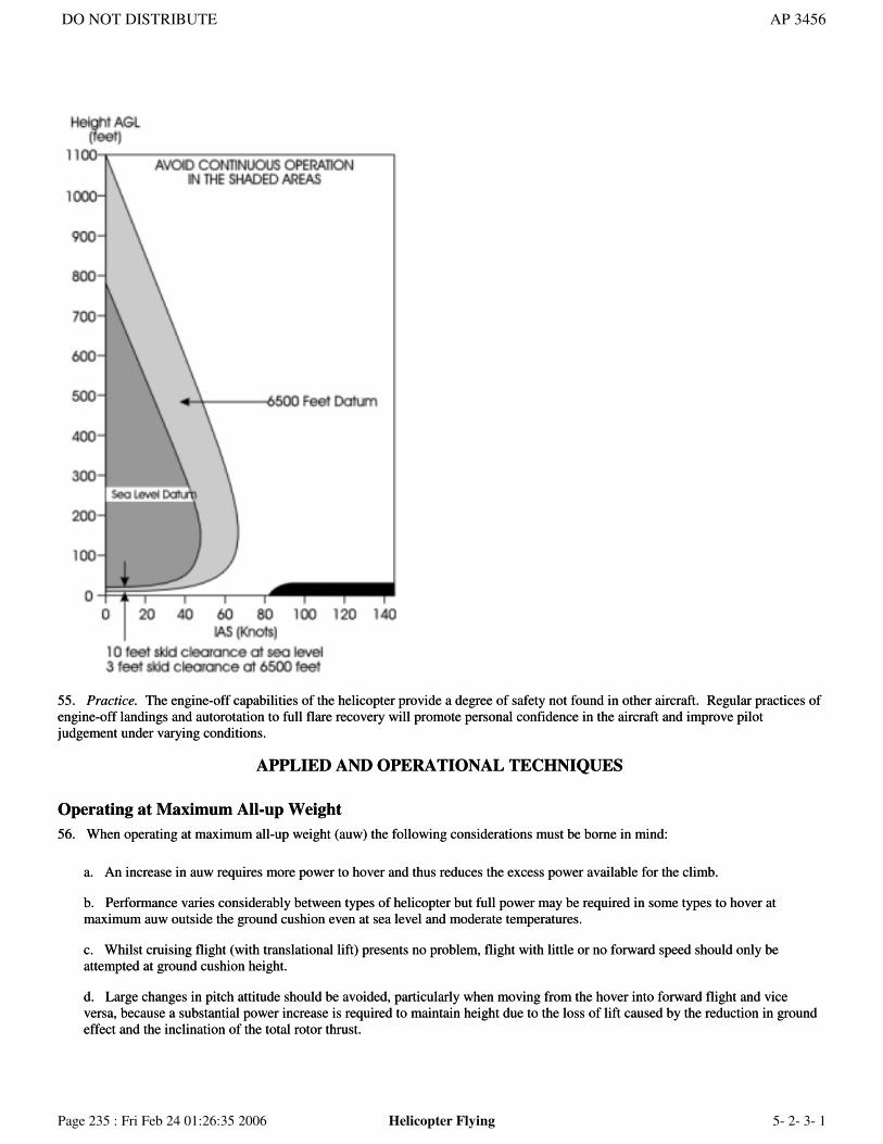
55. Practice. The engine-off capabilities of the helicopter provide a degree of safety not found in other aircraft. Regular practices ofengine-off landings and autorotation to full flare recovery will promote personal confidence in the aircraft and improve pilotjudgement under varying conditions.
APPLIED AND OPERATIONAL TECHNIQUES
Operating at Maximum All-up Weight
56. When operating at maximum all-up weight (auw) the following considerations must be borne in mind:
a. An increase in auw requires more power to hover and thus reduces the excess power available for the climb.
b. Performance varies considerably between types of helicopter but full power may be required in some types to hover atmaximum auw outside the ground cushion even at sea level and moderate temperatures.
c. Whilst cruising flight (with translational lift) presents no problem, flight with little or no forward speed should only beattempted at ground cushion height.
d. Large changes in pitch attitude should be avoided, particularly when moving from the hover into forward flight and viceversa, because a substantial power increase is required to maintain height due to the loss of lift caused by the reduction in groundeffect and the inclination of the total rotor thrust.
DO NOT DISTRIBUTE AP 3456
Page 235 : Fri Feb 24 01:26:35 2006 Helicopter Flying 5- 2- 3- 1
e. In forward flight, the higher the auw the lower will be the airspeed at which the symptoms of retreating blade stall willoccur.
f. It is important to remember that the maximum auw limitation is imposed for structural as well as performance reasons.
Centre of Gravity Considerations
57. In single rotor helicopters the safe range of movement of the centre of gravity (CG) is very small, often being as little as four orfive cm fore and aft of the CG datum, which is usually, but not necessarily, directly below the rotor shaft. The natural hang of thefuselage when hovering in still air conditions changes with CG position, becoming nose-down as the CG moves forward andtail-down as the CG moves back, in relation to the datum.
58. The position of the cyclic stick to maintain the hover will also be affected by the CG position; the stick being closer to itsforward stop when the CG is aft of the datum, and vice versa. A condition could be reached where the CG is so far aft that the cyclicstick will be on its forward stop, purely to maintain the hover, thus making forward flight impossible. If the aircraft is loaded beyondthe maximum aft CG position whilst on the ground, the pilot will find that, on take-off, the aircraft will move backwards and he willhave no forward cyclic control left to stop this movement. The reverse effect will occur if the position of the CG is beyond theforward limit.
59. Since operational use of the helicopter involves the carriage of widely differing loads, it is essential that pilots should take care toassess the weight to be carried and load the aircraft to keep the CG within safe operating limits. On some helicopters the CG willchange as the result of using fuel. The method of calculating these factors is considered in detail in Vol 1, Pt 3, Sect 5, Ch 2.
60. In the tandem rotor configuration the range of CG movement is much greater than in the single rotor helicopter since the pitchingmoments of the fuselage can be corrected by differential collective pitch of the rotors.
Limited Power Operations
61. Many helicopter operations have to be carried out in ambient conditions which limit the power available, or in conditions whenmaximum power is available but inadequate. When operating in tropical conditions, knowing the density altitude becomes ofparamount importance, eg with a pressure altitude of 500 ft and an ambient temperature of 35° C, the density altitude may be as highas 3,000 ft. It is, therefore, important to know the power limitations of the aircraft so as to be able to assess accurately what may beachieved with the power margin available after take-off and before landing. Depending on the power margin available, differenttake-off and landing techniques are required for safe operations; the exact amounts of power required for each type of manoeuvre varywith the type of helicopter being flown.
62. Ideally, the aircraft's performance should be calculated before take-off as part of the pre-flight planning, so that the pilot shouldbe in no doubt as to his power requirements or which technique to use. However, the information required for pre-flight planningmay not be readily available and in such cases the pilot will have to rely upon "rule of thumb" methods to determine the aircraft'scapability.
63. Take-off. The method of assessing the power in hand for take-off is:
a. Hover at normal hover height in the ground cushion and note the power required.
b. Check the maximum power available under the prevailing conditions.
The difference between a and b represents the power margin available and indicates the type of take-off and transition possible.
64. The different types of take-off and transition are:
a. Running Take-off. When the power is limited to such an extent that the aircraft cannot be brought to the hover or only to avery low hover, a running take-off is advisable provided that the take-off run is over smooth flat ground, that no obstacles exist inthe take-off path and that the aircraft has a suitable undercarriage for this type of take-off. The method of making a runningtake-off is to taxi forward into wind and then allow the speed to increase and fly the aircraft off, counteracting any nosedown
DO NOT DISTRIBUTE AP 3456
Page 236 : Fri Feb 24 01:26:35 2006 Helicopter Flying 5- 2- 3- 1
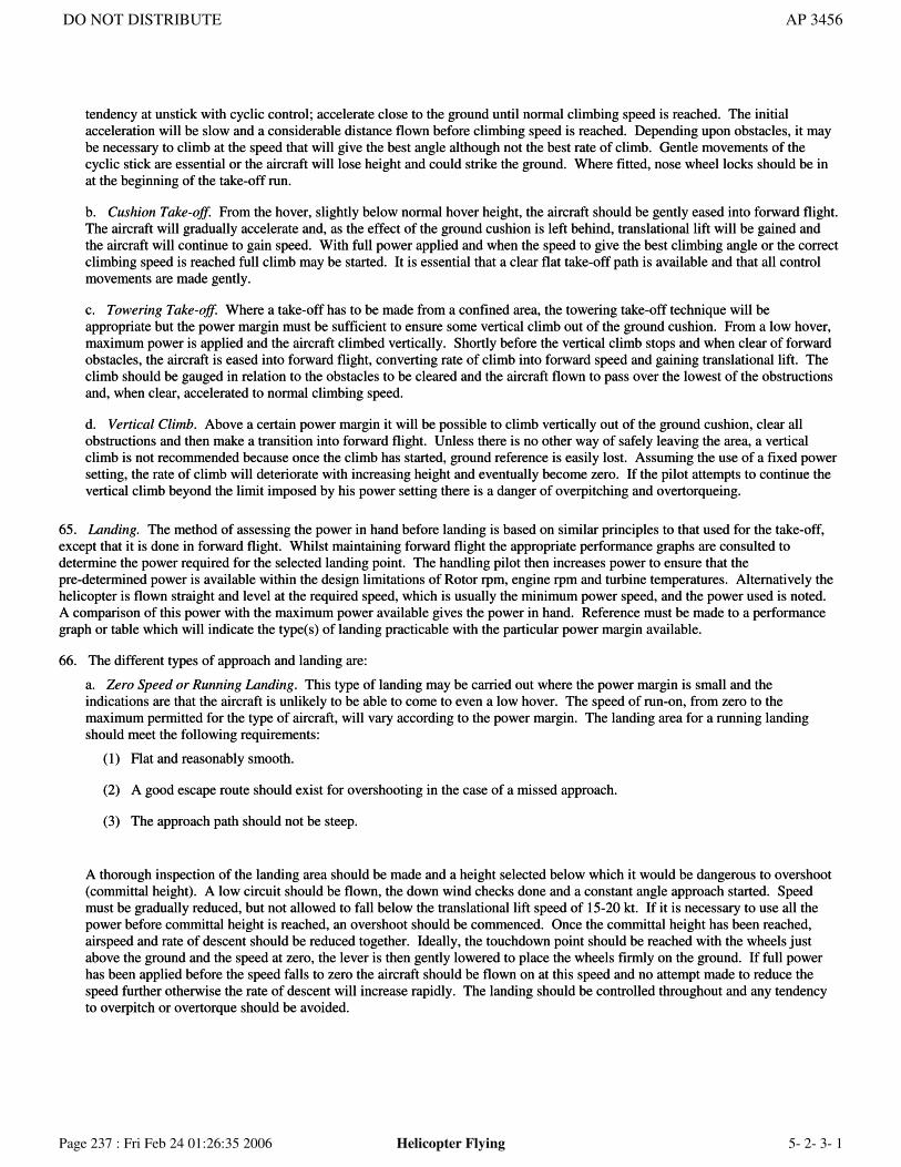
tendency at unstick with cyclic control; accelerate close to the ground until normal climbing speed is reached. The initialacceleration will be slow and a considerable distance flown before climbing speed is reached. Depending upon obstacles, it maybe necessary to climb at the speed that will give the best angle although not the best rate of climb. Gentle movements of thecyclic stick are essential or the aircraft will lose height and could strike the ground. Where fitted, nose wheel locks should be inat the beginning of the take-off run.
b. Cushion Take-off. From the hover, slightly below normal hover height, the aircraft should be gently eased into forward flight.The aircraft will gradually accelerate and, as the effect of the ground cushion is left behind, translational lift will be gained andthe aircraft will continue to gain speed. With full power applied and when the speed to give the best climbing angle or the correctclimbing speed is reached full climb may be started. It is essential that a clear flat take-off path is available and that all controlmovements are made gently.
c. Towering Take-off. Where a take-off has to be made from a confined area, the towering take-off technique will beappropriate but the power margin must be sufficient to ensure some vertical climb out of the ground cushion. From a low hover,maximum power is applied and the aircraft climbed vertically. Shortly before the vertical climb stops and when clear of forwardobstacles, the aircraft is eased into forward flight, converting rate of climb into forward speed and gaining translational lift. Theclimb should be gauged in relation to the obstacles to be cleared and the aircraft flown to pass over the lowest of the obstructionsand, when clear, accelerated to normal climbing speed.
d. Vertical Climb. Above a certain power margin it will be possible to climb vertically out of the ground cushion, clear allobstructions and then make a transition into forward flight. Unless there is no other way of safely leaving the area, a verticalclimb is not recommended because once the climb has started, ground reference is easily lost. Assuming the use of a fixed powersetting, the rate of climb will deteriorate with increasing height and eventually become zero. If the pilot attempts to continue thevertical climb beyond the limit imposed by his power setting there is a danger of overpitching and overtorqueing.
65. Landing. The method of assessing the power in hand before landing is based on similar principles to that used for the take-off,except that it is done in forward flight. Whilst maintaining forward flight the appropriate performance graphs are consulted todetermine the power required for the selected landing point. The handling pilot then increases power to ensure that thepre-determined power is available within the design limitations of Rotor rpm, engine rpm and turbine temperatures. Alternatively thehelicopter is flown straight and level at the required speed, which is usually the minimum power speed, and the power used is noted.A comparison of this power with the maximum power available gives the power in hand. Reference must be made to a performancegraph or table which will indicate the type(s) of landing practicable with the particular power margin available.
66. The different types of approach and landing are:
a. Zero Speed or Running Landing. This type of landing may be carried out where the power margin is small and theindications are that the aircraft is unlikely to be able to come to even a low hover. The speed of run-on, from zero to themaximum permitted for the type of aircraft, will vary according to the power margin. The landing area for a running landingshould meet the following requirements:
(1) Flat and reasonably smooth.
(2) A good escape route should exist for overshooting in the case of a missed approach.
(3) The approach path should not be steep.
A thorough inspection of the landing area should be made and a height selected below which it would be dangerous to overshoot(committal height). A low circuit should be flown, the down wind checks done and a constant angle approach started. Speedmust be gradually reduced, but not allowed to fall below the translational lift speed of 15-20 kt. If it is necessary to use all thepower before committal height is reached, an overshoot should be commenced. Once the committal height has been reached,airspeed and rate of descent should be reduced together. Ideally, the touchdown point should be reached with the wheels justabove the ground and the speed at zero, the lever is then gently lowered to place the wheels firmly on the ground. If full powerhas been applied before the speed falls to zero the aircraft should be flown on at this speed and no attempt made to reduce thespeed further otherwise the rate of descent will increase rapidly. The landing should be controlled throughout and any tendencyto overpitch or overtorque should be avoided.
DO NOT DISTRIBUTE AP 3456
Page 237 : Fri Feb 24 01:26:35 2006 Helicopter Flying 5- 2- 3- 1
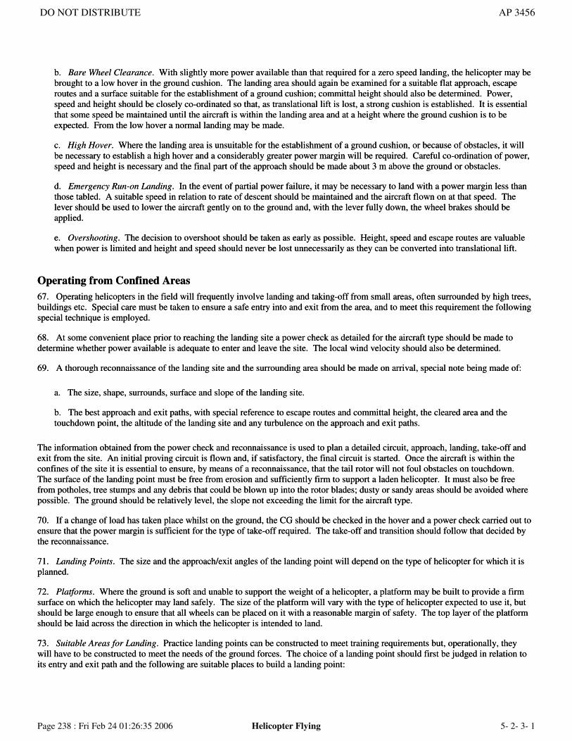
b. Bare Wheel Clearance. With slightly more power available than that required for a zero speed landing, the helicopter may bebrought to a low hover in the ground cushion. The landing area should again be examined for a suitable flat approach, escaperoutes and a surface suitable for the establishment of a ground cushion; committal height should also be determined. Power,speed and height should be closely co-ordinated so that, as translational lift is lost, a strong cushion is established. It is essentialthat some speed be maintained until the aircraft is within the landing area and at a height where the ground cushion is to beexpected. From the low hover a normal landing may be made.
c. High Hover. Where the landing area is unsuitable for the establishment of a ground cushion, or because of obstacles, it willbe necessary to establish a high hover and a considerably greater power margin will be required. Careful co-ordination of power,speed and height is necessary and the final part of the approach should be made about 3 m above the ground or obstacles.
d. Emergency Run-on Landing. In the event of partial power failure, it may be necessary to land with a power margin less thanthose tabled. A suitable speed in relation to rate of descent should be maintained and the aircraft flown on at that speed. Thelever should be used to lower the aircraft gently on to the ground and, with the lever fully down, the wheel brakes should beapplied.
e. Overshooting. The decision to overshoot should be taken as early as possible. Height, speed and escape routes are valuablewhen power is limited and height and speed should never be lost unnecessarily as they can be converted into translational lift.
Operating from Confined Areas
67. Operating helicopters in the field will frequently involve landing and taking-off from small areas, often surrounded by high trees,buildings etc. Special care must be taken to ensure a safe entry into and exit from the area, and to meet this requirement the followingspecial technique is employed.
68. At some convenient place prior to reaching the landing site a power check as detailed for the aircraft type should be made todetermine whether power available is adequate to enter and leave the site. The local wind velocity should also be determined.
69. A thorough reconnaissance of the landing site and the surrounding area should be made on arrival, special note being made of:
a. The size, shape, surrounds, surface and slope of the landing site.
b. The best approach and exit paths, with special reference to escape routes and committal height, the cleared area and thetouchdown point, the altitude of the landing site and any turbulence on the approach and exit paths.
The information obtained from the power check and reconnaissance is used to plan a detailed circuit, approach, landing, take-off andexit from the site. An initial proving circuit is flown and, if satisfactory, the final circuit is started. Once the aircraft is within theconfines of the site it is essential to ensure, by means of a reconnaissance, that the tail rotor will not foul obstacles on touchdown.The surface of the landing point must be free from erosion and sufficiently firm to support a laden helicopter. It must also be freefrom potholes, tree stumps and any debris that could be blown up into the rotor blades; dusty or sandy areas should be avoided wherepossible. The ground should be relatively level, the slope not exceeding the limit for the aircraft type.
70. If a change of load has taken place whilst on the ground, the CG should be checked in the hover and a power check carried out toensure that the power margin is sufficient for the type of take-off required. The take-off and transition should follow that decided bythe reconnaissance.
71. Landing Points. The size and the approach/exit angles of the landing point will depend on the type of helicopter for which it isplanned.
72. Platforms. Where the ground is soft and unable to support the weight of a helicopter, a platform may be built to provide a firmsurface on which the helicopter may land safely. The size of the platform will vary with the type of helicopter expected to use it, butshould be large enough to ensure that all wheels can be placed on it with a reasonable margin of safety. The top layer of the platformshould be laid across the direction in which the helicopter is intended to land.
73. Suitable Areas for Landing. Practice landing points can be constructed to meet training requirements but, operationally, theywill have to be constructed to meet the needs of the ground forces. The choice of a landing point should first be judged in relation toits entry and exit path and the following are suitable places to build a landing point:
DO NOT DISTRIBUTE AP 3456
Page 238 : Fri Feb 24 01:26:35 2006 Helicopter Flying 5- 2- 3- 1

a. On top of a piece of ground higher than the immediate surrounding area.
b. On a "pimple" in a valley where an up-valley approach and down-valley exit is possible, taking account of any prevailingwind.
c. On a curve of a river which is wide enough for the helicopter to be flown over the water on the approach and exit.
d. In the centre of a saddle where the approach may be made across it and the exit carried on in a straight line.
e. On a ridge in the side of a hill where the approach and exit can be made parallel to the hillside.
Mountain Flying
74. Mountain flying poses several special problems and aggravates many others. An appreciation of mountain wind effects, theability to assess aircraft performance accurately and an understanding of the physiological problems involved are necessary if the pilotis to fly the aircraft safely and confidently. Although a general pattern may be laid down for the approach and landing onto specifiedfeatures, because of the changing wind effects, no two approaches are likely to be the same. Smooth, accurate flying is particularlyimportant because on many occasions it will be necessary to fly to the limits of the aircraft's performance and the pilot's ability. Thissubject is discussed in some detail in Pt 2, Sect 3, Ch 4 of this volume.
Low Flying
75. The nature of helicopter operations is such that much flying is done at low level and pilots must have a clear understanding ofthe problems involved. Because of the low speed of helicopters there will be a large variation in groundspeed between the into-windand down-wind case in strong wind conditions, and the effects of turning cross-wind will also be very marked. Any inclination toreduce the airspeed when flying down-wind, in an attempt to maintain a constant groundspeed, must be done with care. Whencarrying out a low level creeping line ahead search, a start should be made from the down-wind end of the area and all turns madeinto-wind. Where turns down-wind are unavoidable, sufficient airspeed should be maintained to ensure a forward airspeed when theturn has been completed.
76. The maintenance of a good look-out and, where necessary, taking prompt avoiding action, is of paramount importance. Thefollowing are the most satisfactory methods of avoiding obstacles that cannot be cleared:
a. When flying approximately into wind, make a quick stop by flaring to reduce speed rapidly, at the same time lowering thelever to avoid gaining height.
b. When flying down-wind, turn through 180° and flare.
A quick stop is not normally attempted if flying down-wind. To clear a high obstacle or rising ground, collective pitch and power areincreased and the attitude, and therefore airspeed, maintained with the cyclic control. The natural tendency to want to make a "cyclicclimb" when nearing an obstacle should be avoided.
Flying at High Altitude
77. As height is gained, control response decreases because of the reduction in air density and added care must be taken to maintaincontrol of attitude. Density altitude will be the same as pressure altitude when the ambient temperature conforms to ISA conditions,but when the temperature for any given height is not the ISA temperature, density altitude should be calculated using a densityaltitude graph, to ensure that the flight will be within the flight envelope. For example, at a pressure altitude of 6,000 ft with airtemperature of +15°C, the density altitude would be 7,400 ft.
78. For the best rate of climb, IAS must be reduced as height is gained so that a TAS is maintained at which maximum excessclimbing power is available. Maximum indicated cruising speed must also be reduced with height because the higher blade angle ofattack required to obtain the necessary rotor thrust in the less dense air results in the retreating blade reaching its stalling angle at alower forward IAS than at sea level. Control response of the main and tail rotors is reduced and violent manoeuvres and steep turns ataltitude should be avoided since the sudden onset of blade stall will produce a nose-up rolling attitude from which it may be difficult
DO NOT DISTRIBUTE AP 3456
Page 239 : Fri Feb 24 01:26:35 2006 Helicopter Flying 5- 2- 3- 1

to recover.
Instrument Flying
79. Aircrew Manuals for different types of helicopter will specify the limitations placed on the aircraft for the purposes of instrumentflying and these normally include maximum and minimum airspeeds, maximum altitude and maximum angle of bank. Unless a flightcontrol system is fitted, it is impossible to hover a helicopter by sole reference to instruments.
80. Control of Attitude and Airspeed. A change of attitude in the pitching plane is synonymous with a change of airspeed, theinstruments used to determine the change of attitude being the attitude indicator, and the airspeed indicator. In the rolling plane, bankattitude is shown only on the attitude indicator and, since no other instrument is normally fitted to show bank indication, thisinstrument is always duplicated. The second instrument has an alternative power supply and, in addition, an emergency power supplyin the event of total electrical failure.
81. Control of Height. Change of height is effected by use of the collective lever. At a constant attitude/airspeed in level flight,tendencies to climb or descend are detected by reference to the vertical speed indicator and corrected by small adjustments of thecollective lever. A change of attitude/airspeed will result in a height change, but any attempt to recover to the original conditionsmust be treated as two separate control movements, firstly attitude change, to restore the original airspeed and, secondly, a collectivelever movement to restore the original height.
82. Control in the Yawing Plane. A conventional slip indicator is fitted to assist the pilot to maintain balanced flight and agyrocompass provides the necessary heading information. Any movement of the collective lever will require a correspondingadjustment of the yaw pedals to counteract the alteration in main rotor torque.
83. Approach Aids and General Instrument Flying. Within the helicopter's speed range all normal types of airfield and runwayapproach procedures can be flown, although initial difficulty may be experienced by the ground controller because the slow speed ofthe helicopter often necessitates relatively large corrections to compensate for drift.
84. Icing. Flight when icing conditions prevail should be avoided. Apart from the normal engine icing, airframe icing is a serioushazard because:
a. Blade loading is high and a small amount of ice accretion on the blades is likely to cause a large deterioration in rotorperformance.
b. An increase in blade weight due to ice accretion causes a significant increase in the centrifugal reaction which may imposeunacceptable loads on the rotor hub.
c. Even small inequalities in the amount of ice accretion on individual blades will cause blade inbalance and since blade balanceis very critical, severe vibration may result.
See also this Section Chap 3 and Annex.
Night Flying
85. Provided the helicopter is fitted with the normal flight instruments, night flying presents no particular problems. Ideally,illuminating flares are fitted to the helicopter for all flights at night to provide ground illumination in case of an emergency landing.Each flare is attached to a small parachute which opens when the flare is fired and so increase the flare's time in the air. In case of anemergency, eg engine failure, the first flare is fired immediately to provide light to enable the pilot to choose a suitable landing area.The second flare is fired at a later stage to provide further illumination for the touchdown.
86. Normal landing aids at night are in the form of lights on the ground set up in various configurations to give the pilot azimuth andelevation indications. These lights may vary from hand held electric torches to crossed headlights provided by stationary vehicles.Night vision goggles may also be used for night operations and training.
Formation Flying
87. There are two categories of formation flying:
DO NOT DISTRIBUTE AP 3456
Page 240 : Fri Feb 24 01:26:35 2006 Helicopter Flying 5- 2- 3- 1

a. Close Formation. Close formation is used mainly for demonstration and display purposes.
b. Tactical Formation. Tactical formation is used primarily for Army support operations when a large number of helicopters areinvolved in the dropping of troops into a forward area, or when a large supply drop is required. This formation is flown at verylow level.
88. Leadership. The duties of a leader of a close formation remain essentially the same as for fixed-wing formation flying: allmatters relating to the safety, positioning and tactics of the formation being his responsibility. In tactical formation, the spacing ofindividual aircraft is much greater and, therefore, the safety of each aircraft becomes the responsibility of individual pilots, but theleader still retains overall control of navigation and tactics.
89. Close Formation - Basic Positions. The following types of formation (described further in Pt 2, Sect 2, Chap 6) can be flown:
a. Vic - three or more aircraft
b. Box - four aircraft.
c. Finger Four - four aircraft.
d. Echelon - two or more aircraft.
e. Line Astern - two or more aircraft.
f. Line Abreast - two or more aircraft.
All horizontal spacing is related to rotor diameter - usually one rotor diameter between tips of main rotor blades of adjacent aircraft -and all aircraft are displaced vertically or "stepped-up" above aircraft ahead. Since there is only a small margin between theformation's cruising and maximum speeds, angles of bank are kept low in all types of formation, except line astern, to assist pilots inkeeping the correct position and spacing.
90. Tactical Formation. Formations consist of two or more aircraft and horizontal spacing is at least two rotor diameters betweenaircraft. Vertical spacing is not so critical as in close formation because of the greater distances between aircraft; the only stipulationis that following aircraft should not fly below the height of the leader.
91. Pre-planning. Operational tactical formations of this type will require extensive pre-planning of routes to achieve maximumprotection and to avoid known obstacles and enemy positions. When only the lead aircraft carries a navigator the pilots of followingaircraft will have to do a certain amount of their own navigation as well as maintaining position; hence the need for extensivepre-planning.
5-2-3-1 Fig 1a
DO NOT DISTRIBUTE AP 3456
Page 241 : Fri Feb 24 01:26:35 2006 Helicopter Flying 5- 2- 3- 1

5-2-3-1 Fig 1b
Helicopter Flying
Chapter 2 - External Load Carrying
Introduction
1. The helicopter can, more conveniently, carry a greater variety of loads externally than internally, particularly in the case of bulkyor unusually-shaped items. Such loads may be carried on external load fitments such as panniers, or by attachment to underslungload-carrying gear. These facilities also permit loading and unloading in areas where the aircraft cannot land.
Crew Training
DO NOT DISTRIBUTE AP 3456
Page 242 : Fri Feb 24 01:26:35 2006 Helicopter Flying 5- 2- 3- 2

2. It is essential that all personnel concerned with flying, marshalling and loading be thoroughly briefed and fully understand therole of other team members and the problems associated with their tasks.
Aircrew Pre-flight Checks
3. Before commencing external load carrying all the necessary equipment should be checked for serviceability with particularreference to release and emergency release mechanisms.
External Loads
4. Loading Teams. When hand-marshalling, the loading team consists of a minimum of two men: one marshaller and one loader.When voice-marshalling, the team may be reduced to one loader, although it is preferable to have a marshaller as well, in case ofdifficulty. At night, a marshaller should always be present.
5. Hand-marshalling. In the event of a hand-marshalling operation, the marshaller is positioned in front of the helicopter and byusing the hand signals depicted in the table below, he directs the helicopter to a position over the load. The movement of thehelicopter is monitored by the loader and when it is suitably positioned he hooks up the load and signals the marshaller when the loadis secure and ready for pick-up.
Table 1 - Hand Marshalling Signals
DO NOT DISTRIBUTE AP 3456
Page 243 : Fri Feb 24 01:26:36 2006 Helicopter Flying 5- 2- 3- 2

DO NOT DISTRIBUTE AP 3456
Page 244 : Fri Feb 24 01:26:36 2006 Helicopter Flying 5- 2- 3- 2

6. Voice-marshalling. During voice-marshalling, the crewman directs the helicopter over the load and informs the pilot when theload is ready for lifting.
Off-loading
7. Marshalled. The marshaller stands in a position some 20 to 30m up-wind of the point where the load is to be dropped. Thehelicopter comes to a high hover over the pre-selected point and is thereafter directed by the marshaller. The pilot is then directed todescend slowly until the load is on the ground. Further marshalling signals are given to release the load and to indicate that the load isclear and the aircraft free to depart.
8. Unmarshalled. Loads may be off-loaded without the aid of a marshaller. The pilot positions the helicopter, under the directionsof a crewman, over the
selected point of off-loading and slowly descends; as the weight is taken on the ground the load can be released either automaticallyor manually by the crewman or pilot.
Pilot Technique
9. During Loading. The pilot must identify the particular marshaller as soon as possible on the approach and should follow themarshalling instructions throughout the operation.
10. Hook-up. Once hook-up is complete, power is applied gently to take up the slack and at the same time small corrections may bemade to ensure that the helicopter is vertically above the load. This will prevent dragging of the load as the weight is taken up andalso minimizes any swinging of the load as it is lifted clear of the ground.
11. Lifting Technique. After take-off, a power margin check is made to ensure that sufficient power is available to climb away. Atowering technique is normally employed to ensure clearance of immediate obstacles.
12. During Flight. It is essential that smooth control movements are made to obviate any possibility of causing unnecessaryload-swinging or exceeding the aircraft's airframe limitations.
13. Load Oscillation. If swinging of the load does develop, it is felt as an aircraft oscillation and any attempt to dampen it by use ofthe cyclic control normally leads to over-controlling and so worsens the situation. The normal procedure is to reduce forward speedgently but if this does not have the desired effect, application of bank and/or power may provide a centrifugal force to dampen theoscillation. An uncontrollable load should be jettisoned.
14. Area Safety. Built-up areas should be avoided and, during low flying, a safe load clearance above obstacles must be maintained.Load switch procedures, designed to obviate load jettison, should be adhered to.
Helicopter Flying
Chapter 3 - Tropical and Cold Weather Operation
Introduction
1. The tropical regions of the world cannot be classified under any one set of characteristics; similarly, the term “cold weatheroperation” can properly be applied to operations inside the Arctic or Antarctic Circles or, in a hard winter, to day-to-day operations inthe European area. Although aircrew will be given specific information on the problems involved during training, they should alsoseek local knowledge whenever they are first posted to a particular area.
TROPICAL OPERATION
High Temperature and Humidity
DO NOT DISTRIBUTE AP 3456
Page 245 : Fri Feb 24 01:26:36 2006 Helicopter Flying 5- 2- 3- 3

2. High ambient temperatures reduce air density and adversely affect performance in much the same way as an increase in altitude;furthermore, this reduction in performance is aggravated by high humidity. Both engine and rotor performance are adversely affected.Under certain conditions, the maximum all-up weight may have to be restricted to something below the maximum quoted in theAircrew Manual to ensure adequate performance.
3. Particular care is required if operating from marginal landing sites well above sea level in conditions of high temperature andhumidity, where all the circumstances combine to reduce performance margins.
Sand and Dust
4. Most helicopters have more operating parts exposed to the eroding action of sand and dust than comparable fixed-wing aircraftand special precautions are necessary. Prolonged hovering over sandy or dusty ground should be avoided otherwise main and tailrotor blades may be seriously damaged and rapid wear will occur in any bearing penetrated. Bearings should be purged regularly withgrease and all moving parts and mechanisms inspected frequently.
5. Engine intake air filters should be fitted; these normally consist of a fine-mesh sand filter or a centrifugal-action separator.However, care should be taken when operating in rain with the fine-mesh filter because the combination of water and dust can resultin a serious restriction of the airflow to the engine.
6. Because of the downwash of the main rotors, helicopters can produce their own “dust storm” and thus create difficulties forthemselves and others. It is particularly important that the inside of all helicopters should be kept clean at all times otherwise dustand sand stirred up by the rotor blades will enter the eyes of crew and passengers and foul equipment. Air and ground crews shouldwear goggles or eye-shields, and aircraft doors, hatches and windows should be kept shut. Ground marshallers should positionthemselves as well clear of the landing area as circumstances permit. For the same reasons, formation take-offs and landings shouldbe restricted and the distances between aircraft may have to be increased.
Weather
7. Rapid changes in weather are likely in some tropical areas and violent thunderstorms and sandstorms can form with little warningand extend quickly over a large area. The turbulence arising from such storms can be very severe and the associated electricaldisturbances are likely to cause serious deterioration in radio communications. Unless it is of vital operational necessity, helicopterpilots should avoid flying in or near such storms and should acquaint themselves with the weather conditions likely to be encounteredin their area of operations generally, and before every flight, although this may not always be possible when operating away fromfixed bases.
Navigation
8. The tropical areas of the world are vast and radio communications are not usually as readily available as in, say, North Americaor Europe; moreover, tropical storms can cause serious deterioration in the facilities that do exist. An additional problem is that somemaps of these areas are not entirely reliable. The vagaries of the weather, poor radio facilities, inadequate maps and the fact thathelicopters operate at comparatively low altitudes and speeds, all combine to make navigation difficult.
9. Routes should be planned to make maximum use of clearly defined line features and, where it is necessary to fly overinhospitable country, frequent position reports should be made and any deviations from flight plan passed to the controlling authority.In jungle country, in particular, where the jungle canopy can close over a crashed or force-landed aircraft, flights should, if possible,be planned to follow well defined lines of communication, eg roads, railways, rivers etc.
COLD WEATHER OPERATION
Icing
10. Icing presents a particular problem when considered in relation to helicopter flying. In the really cold areas of the world, severeicing is not usually encountered because it is often too cold and because the cumulus and cumulo-nimbus-type cloud is not oftenfound in these areas. The winter in the more temperate regions is potentially more hazardous.
11. In turbine-engine helicopters, engine icing is a problem and although an anti-icing system is fitted, it can deal with onlycomparatively light icing.
DO NOT DISTRIBUTE AP 3456
Page 246 : Fri Feb 24 01:26:36 2006 Helicopter Flying 5- 2- 3- 3

12. Ice accretion on main and tail rotor blades is a serious problem and the matter of providing an effective de-icing system is underconstant review and development. The rotor blades are finely balanced and any uneven build-up of ice on them creates severevibration and handling difficulties, quite apart from the fact that the aerodynamic qualities of the blades are modified and diminished.Severe icing would quickly result in insufficient lift being generated to support the aircraft’s weight, particularly if general airframeicing had increased the weight significantly.
13. Icing may or may not form on the windscreen and is not a reliable indicator of icing conditions. However, any increase incollective lever position (power) to maintain straight and level flight could be indicative and this and any unusual vibration or“nibbling” sensation on the controls must be regarded as warning that icing conditions exist.
14. The hydraulic jacks or manually-operated pitch operating arms are more or less exposed and are therefore subject to iceformation. In some cases, ice or pack snow melts on the warm transmission and, having run down on to the jacks or control runs,refreezes. Prolonged flight under these conditions may cause the collective lever to freeze solidly and the cyclic may be restrictedwithin the small diameter of its normal travel for maintaining cruising flight. To keep them free, periodic exaggerated movement ofboth collective and cyclic controls is recommended.
15. Windscreen icing can “blind” the pilot completely and although some helicopters have an effective de-icing system, in aircraftwith the bubble-type canopy there is little that can be done except to quit the icing conditions, or land as soon as possible.
16. Starting up or closing down with ice on the rotor blades can cause ground resonance. To prevent this, never start up with ice onany part of the blade.
Handling Techniques
17. Ice under the skids or wheel may cause the helicopter to spin during rotor engagement or when the engine is throttled backquickly during engine and transmission checks. Care is necessary, to ensure that the cyclic is held in the central position during thesechecks.
18. If the aircraft has been landed in a dispersal which is covered with slush or wet snow, the supercooled skids may cause thehelicopter to freeze to the ground and thus present an unwary pilot with a problem on the next take-off. In this case, the lever shouldbe used to reduce the weight on the skids and the aircraft should then be yawed carefully to ensure that it is free for take-off.
19. Where there has been a new fall of snow, a prolonged run-up should be employed to blow away the fresh snow. However,because of the reduced visibility caused by the resulting “snow cloud”, it will be necessary to use a reference point within theperiphery of the rotor blades. Movement at a low hovering height should be avoided and a vertical climb-out technique employed.Similarly, returning to the hover over areas of fresh snow can be hazardous and an approach should be made to a specific object, suchas a bush or tree stump, which should be used as a hovering reference whilst the snow is being blown away by the rotor downwash.This reference should be held inside the rotor periphery to prevent it being lost from sight in the disturbed snow. In cases where nosuch reference is available, several low flypasts may blow away most of the loose snow; they should be made at sufficient speed toensure that there is always an area of clear vision in front of the aircraft.
20. Depth perception is difficult over large areas of unbroken snow, particularly for the uninitiated, and such areas should be avoidedfor practising quick-stops or autorotations with a powered recovery. Tree lines, fences, clear roads, tracks, etc will provide referencesto assist in judging height.
21. A landing on fresh snow, particularly at an unfamiliar site, should be tackled with extreme care since there will be doubt aboutthe depth of snow and the condition and nature of the underlying ground. The weight of the aircraft should be transmitted to thelanding gear carefully, gradually, and vertically so that an assessment can be made of the ability of the site to take all the aircraft’sweight and permit shutdown. Throughout this procedure the pilot must be ready to take-off immediately should circumstanceswarrant it.
22. Snow that has a strong crust must be treated with extreme caution; the crust may give way during landing, causing a violent roll.If the crust allows the skids to penetrate to the underlying soft snow, care must be taken not to allow any yaw during the final settling,since a skid which has slid underneath the hard crust may give an unexpected off-balance lateral force on the next take-off. If, duringlanding, the undercarriage penetrates below the top surface of the snow, the tail rotor will be much nearer to the surface of thesnow.
DO NOT DISTRIBUTE AP 3456
Page 247 : Fri Feb 24 01:26:36 2006 Helicopter Flying 5- 2- 3- 3

Navigation
23. Navigation across wide expanses of unbroken snow is always difficult and maximum use must be made of any line features suchas power cables, trees, ridges, etc. During blizzard conditions, when the pilot has both a navigation and orientation problem, it maybe advantageous to follow line features on the down-wind side, so that any gusting will tend to yaw the helicopter towards the linefeature, ie in a direction which permits the pilot some ground reference, rather than where he will be confronted with an expanse ofsnow. Similarly, following a line feature on the downwind side means that only a small turn will be required to force-land into windshould the need arise and a visual reference will be available throughout.
Snow Clearance in Dispersals
24. The dispersal area is likely to become congested during snow clearance operations and movements into, through and out ofdispersal should be made with extreme caution. This is particularly important when various agencies are involved in snow clearance,eg helicopters, snow ploughs, blowers etc where each may be creating individual and separate “snow storms”. Ridges of hard snoware often formed during snow clearance operations and these are sometimes hard to see; any hover taxiing should be done at asufficient height to avoid these ridges.
Helicopter Flying
Annex to Chapter 3 - Helicopter Icing
Introduction
1. Through practical experience, a wealth of knowledge has been accumulated operating fixed-wing aircraft in icing conditions;there are some other considerations, however, with rotary-wing aircraft.
2. Conditions for Ice Formation. The conditions in which ice formation is possible are given below:
a. Icing may occur in conditions of high humidity when the ambient air temperature is at or below 0°C.
b. Due to local reduction in pressure, icing may occur in conditions of high humidity when the ambient air temperature is above0°C.
High humidity occurs in all forms of precipitation, cloud and fog, or in air close to these conditions.
3. Categories. For convenience, helicopter icing is considered under three headings, in the following order of priority:
a. Rotor system icing.
b. Engine icing.
c. Airframe icing.
ROTOR SYSTEM ICING
Icing Effects on Main Rotor System
4. The primary effect of ice on the rotor system is drag; the secondary effect is loss of lift due to the change in aerodynamicefficiency of the blade. The way in which ice forms on the blade is affected by five main factors.
a. Temperature.
b. Liquid content and droplet size.
DO NOT DISTRIBUTE AP 3456
Page 248 : Fri Feb 24 01:26:36 2006 Helicopter Flying 5- 2- 3- 3A
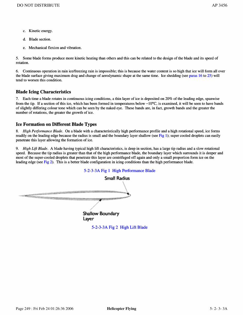
c. Kinetic energy.
d. Blade section.
e. Mechanical flexion and vibration.
5. Some blade forms produce more kinetic heating than others and this can be related to the design of the blade and its speed ofrotation.
6. Continuous operation in rain ice/freezing rain is impossible; this is because the water content is so high that ice will form all overthe blade surface giving maximum drag and change of aerodynamic shape at the same time. Ice shedding (see paras 16 to 25) willtend to worsen this condition.
Blade Icing Characteristics
7. Each time a blade rotates in continuous icing conditions, a thin layer of ice is deposited on 20% of the leading edge, spanwisefrom the tip. If a section of this ice, which has been formed in temperatures below −10°C, is examined, it will be seen to have bandsof slightly differing colour tone which can be seen by the naked eye. These bands are, in fact, growth bands and the greater thenumber of rotations, the greater the growth of ice.
Ice Formation on Different Blade Types
8. High Performance Blade. On a blade with a characteristically high performance profile and a high rotational speed, ice formsreadily on the leading edge because the radius is small and the boundary layer shallow (see Fig 1); super cooled droplets can easilypenetrate this layer allowing the formation of ice.
9. High Lift Blade. A blade having typical high lift characteristics, is deep in section, has a large tip radius and a slow rotationalspeed. Because the tip radius is greater than that of the high performance blade, the boundary layer which surrounds it is deeper andmost of the super-cooled droplets that penetrate this layer are centrifuged off again and only a small proportion form ice on theleading edge (see Fig 2). This is a better blade configuration in icing conditions than the high performance blade.
5-2-3-3A Fig 1 High Performance Blade
5-2-3-3A Fig 2 High Lift Blade
DO NOT DISTRIBUTE AP 3456
Page 249 : Fri Feb 24 01:26:36 2006 Helicopter Flying 5- 2- 3- 3A

10. Tail Rotor Blades. So few problems have been encountered with icing of the tail rotor blades that it is unnecessary to go intogreat detail; ice is picked up on only 20% of the blade from the root end towards the tip. Although ice does build on the pitch changemechanism, this can be kept clear by regularly cycling the controls.
Ice Formation at Different Temperatures
11. Ice Formation at, or Just Below, Freezing Point. Between 0°C and −3°C ice will form in natural icing conditions on the leadingedge of the blades from the blade root towards the tip covering about 70% of the span and 20% of the chord from the tip of theleading edge, the remaining 30% of the span at the tip being free of ice due to kinetic heating. If the blade ice is allowed to build up,the maximum accretion point will be the mid-point of this area, with another area of high accretion around the blade root caused byturbulence (see Fig 3). The ice formed on the leading edge at these relatively high temperatures will have the classical mushroomshape. At the blade root there may also be a degree of run-back which, in itself, is not important as little lift is produced in thisarea.
5-2-3-3A Fig 3 Blade Ice Coverage at Temperatures Just Below Freezing Point
12. Ice Formation at Temperatures Between −3°C and −15°C. It has been shown that at −3°C about 70% of the leading edge spanwill be covered by ice. As the temperature decreases, ice is deposited further along the blade until 100% coverage from root to tiptakes place (see Fig 4) the lower temperature having overcome the kinetic heating. With 100% coverage of the leading edge, dragbecomes very high and, if this ice cannot be shed, the drag will increase to a point where power is limited.
5-2-3-3-A Fig 4 Blade Ice Coverage at Temperatures Between -3 deg C and -15 deg C
DO NOT DISTRIBUTE AP 3456
Page 250 : Fri Feb 24 01:26:36 2006 Helicopter Flying 5- 2- 3- 3A
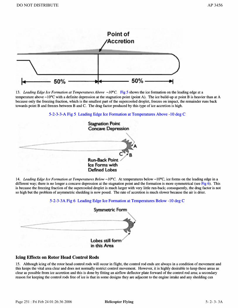
13. Leading Edge Ice Formation at Temperatures Above −10°C. Fig 5 shows the ice formation on the leading edge at atemperature above −10°C with a definite depression at the stagnation point (point A). The ice build-up at point B is heavier than at Abecause only the freezing fraction, which is the smallest part of the supercooled droplet, freezes on impact, the remainder runs backtowards point B and freezes between B and C. The drag factor produced by this type of ice accretion is high.
5-2-3-3-A Fig 5 Leading Edge Ice Formation at Temperatures Above -10 deg C
14. Leading Edge Ice Formation at Temperatures Below −10°C. At temperatures below −10°C, ice forms on the leading edge in adifferent way; there is no longer a concave depression at the stagnation point and the formation is more symmetrical (see Fig 6). Thisis because the freezing fraction of the supercooled droplet is much larger with very little run-back; consequently, the drag factor is notso high but the problem of asymmetric shedding is now posed. The rate of accretion is much slower because the air is drier.
5-2-3-3A Fig 6 Leading Edge Ice Formation at Temperatures Below -10 deg C
Icing Effects on Rotor Head Control Rods
15. Although icing of the rotor head control rods will occur in flight, the control rod ends are always in a condition of movement andthis keeps the vital area clear and does not normally restrict control movement. However, it is highly desirable to keep these areas asclear as possible from ice accretion and this is done by fitting an airflow deflector plate forward of the control rod area; a secondaryreason for keeping the control rods free of ice is that in some designs they are adjacent to the engine intake and any shedding can
DO NOT DISTRIBUTE AP 3456
Page 251 : Fri Feb 24 01:26:36 2006 Helicopter Flying 5- 2- 3- 3A

result in engine ice ingestion (see also para 27).
Natural Ice Shedding
16. All main rotor blades have some degree of self-shedding and this always starts at a point 30% outboard from the blade root andcontinues to the tip. The reason for this is that, at this point, the blade is subject to mechanical forces and flexion and vibration are attheir maximum here. The characteristics of the high lift blade are much better for natural shedding than those of the stiffer, highperformance blade with its weak boundary layer.
17. Before any shedding can take place in the natural shedding range, sufficient ice must have been built up; this varies withdifferent types of helicopters and blade design.
18. Flight in continuous icing conditions is not dangerous provided that the helicopter is not flown in temperatures at which naturalshedding cannot be guaranteed; this temperature limit is known as the critical shedding temperature.
19. Determination of Critical Shedding Temperature. The critical shedding temperature is determined by test flying, at the hover, inan icing rig over a wide range of temperatures, water content and droplet size. The temperatures at which shedding is no longerreliable are carefully bracketed, but have to be exceeded under carefully controlled test conditions. These temperature limits are clearcut and the icing rig test flying is followed by free flight over a wide time and condition range in icing cloud, freezing fog and wet anddry snow. There is a need to repeat many of these conditions in free flight with varying quantities of ice on the blades. This isbecause, whilst it may appear that conditions are satisfactory in the hover and low speed manoeuvres where the ice has been retained,in forward flight (eg climbing, descending, steep turns and autorotation), asymmetrical shedding may take place.
20. Asymmetric Shedding. Below critical shedding temperature, ice may be retained on all blades for some time; however, one ormore blades can suddenly shed its ice, giving an asymmetric condition. If asymmetric shedding occurs in flight it can cause violentvibration, possibly leading to destruction. In such conditions, the only course is to land immediately and shut down as soon aspossible, even if this means using the rotor brake harshly.
21. Damage to the Tail Rotor by Shed Ice. The incident rate of damage to the tail rotor from ice shed from the main rotors is verylow and may amount only to slight denting of the leading edge, not sufficient in itself to cause vibration or balance problems.
Blade Anti-icing
22. The equipment for blade anti-icing consists of an electrical matrix which covers 20% of the leading edge chordwise from the tipalong the length of the blade. Heat is phased into this matrix in different sectors, timed to coincide with the natural shedding cycle, iewhen sufficient ice has built up.
23. This works well until the heat application and the natural shedding cycle get out of phase; heat may then be applied at the wrongtime. This causes run-back, the ice reforming further back along the chord line, causing the blade CG to move backwards which, inturn, causes imbalance and flutter; it can also cause a residual build-up of ice. The extreme case is the failure of heating to one bladecausing asymmetric problems.
24. The power supply for the matrix equipment is a drain on the electrical resources and, since the only satisfactory solution wouldbe to heat the whole blade, a generator large enough to do this would impose weight installation problems.
25. Much research is going into solving this problem, but no clear solution is imminent. The only free, untapped source of heat thatexists is from the engine efflux, but, until this can be harnessed to provide an efficient de-icing system, natural shedding and itsrestrictions must be accepted.
ENGINE ICING
Turbine Engine Icing
26. The only ice produced on a turbine engine is at the throat near the first compressor stage. This is not an insurmountable problemas there is sufficient heat available from hot air bleeds and hot oil, to heat this area, and the inlet guide vanes (where fitted).
27. Because of their delicate construction however, there is a problem of ice ingestion by high performance turbines. A sudden slugof slush, even as low as 350cc water equivalent, can put out the engine flame. Momentum separators are effective in preventing the
DO NOT DISTRIBUTE AP 3456
Page 252 : Fri Feb 24 01:26:36 2006 Helicopter Flying 5- 2- 3- 3A
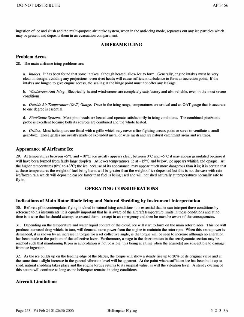
ingestion of ice and slush and the multi-purpose air intake system, when in the anti-icing mode, separates out any ice particles whichmay be present and deposits them in an evacuation compartment.
AIRFRAME ICING
Problem Areas
28. The main airframe icing problems are:
a. Intakes. It has been found that some intakes, although heated, allow ice to form. Generally, engine intakes must be veryclean in design, avoiding any projections; even rivet heads will cause sufficient turbulence to form an accretion point. If theintakes are hinged to give engine access, the sealing at the hinge point must not offer any leakage.
b. Windscreen Anti-Icing. Electrically-heated windscreens are completely satisfactory and also reliable, even in the most severeconditions.
c. Outside Air Temperature (OAT) Gauge. Once in the icing range, temperatures are critical and an OAT gauge that is accurateto one degree is essential.
d. Pitot/Static Systems. Most pitot heads are heated and operate satisfactorily in icing conditions. The combined pitot/staticprobe is excellent because both its sources are combined and the whole heated.
e. Grilles. Most helicopters are fitted with a grille which may cover a fire-fighting access point or serve to ventilate a smallgear-box. These grilles are usually made of expanded metal or wire mesh and are natural catchment areas and ice traps.
Appearance of Airframe Ice
29. At temperatures between −5°C and −10°C, ice usually appears clear; between 0°C and −5°C it may appear granulated because itwill have been formed from fairly large droplets. At lower temperatures, ie at −15°C and below, ice appears whitish and opaque. Atthe higher temperatures (0°C to +3°C) the ice, because of its appearance, may appear much more dangerous than it is; it is certain thatat these temperatures the weight of fuel being burnt will be greater than the weight of ice deposited but this is not the case with rainice/frozen rain which will deposit clear ice faster than fuel is being used and will not shed naturally at temperatures normally safe tofly in.
OPERATING CONSIDERATIONS
Indications of Main Rotor Blade Icing and Natural Shedding by Instrument Interpretation
30. Before a pilot contemplates flying in cloud in natural icing conditions it is essential that he can interpret these conditions byreference to his instruments; it is equally important that he is aware of the aircraft temperature limits in these conditions and at notime is it wise that he should attempt to exceed them - except in an emergency and then he must be aware of the consequences.
31. Depending on the temperature and water liquid content of the cloud, ice will start to form on the main rotor blades. This ice willproduce increased drag which, in turn, will demand more power from the engine to maintain the rotor rpm. When this extra power isdemanded, it is shown by an increase in torque for a set collective angle, ie the torque will be seen to increase although no alterationhas been made to the position of the collective lever. Furthermore, a stage in the deterioration in the aerodynamic section may bereached such that maintaining Rrpm in autorotation is not possible; this being at a time when the engine(s) are susceptible to damagefrom ice ingestion.
32. As the ice builds up on the leading edge of the blades, the torque will show a steady rise up to 20% of its original value and atthe same time a slight increase in the general vibration level will be apparent. At the point where sufficient ice has been built up toshed, natural shedding takes place and the engine torque returns to its original value, as will the vibration level. A steady cycling ofthis nature will continue as long as the helicopter remains in icing conditions.
Aircraft Limitations
DO NOT DISTRIBUTE AP 3456
Page 253 : Fri Feb 24 01:26:36 2006 Helicopter Flying 5- 2- 3- 3A

33. Limitations on flying in icing conditions are defined in the relevant Aircrew Manual and are mandatory; flight in icing conditionsis only permitted if the aircraft is suitably equipped or is modified to the necessary standard (eg intake door configuration, OATgauge, lighting etc).
34. The Aircrew Manual or Release to Service for the particular helicopter may also need to state the following:
a. The accuracy of the OAT gauge and, therefore, the maximum indicated temperature at which 0°C ambient air temperature canbe expected.
b. The maximum temperature at which engine icing could be expected.
c. The minimum gas generator rpm, with time limits, for effective engine anti-icing.
d. The areas where icing may be expected at temperatures above 0°C.
Helicopter Flying
Chapter 4 - Mountain Flying
Introduction
1. An ability to transport personnel and equipment efficiently in mountainous terrain is fundamental to Support and Search& Rescue helicopter operations. An awareness of the effects of altitude on helicopter performance and a sound knowledge of thetechniques which may be used to cope with unusual and often extreme meteorological conditions are essential for safe mountainflying.
Density Altitude and Performance
2. Helicopters are affected by variations in air density, caused by a change in altitude or temperature or a combination of both.Before operating in mountainous regions pilots need to be aware of the prevailing density altitude and its effect on helicopterperformance.
3. Density Altitude. Density altitude is defined as the height in the standard atmosphere (above or below mean sea level) to whichthe actual density at any particular point corresponds. Density altitude may be determined from graphs found in helicopter OperatingData Manuals (ODM), and AP 3456 Vol 1, Part 3, Sect 3, Chap 1. Alternatively the following formula may be used:
Density Altitude = Pressure Altitude ±(120t)
(where t is the difference between local airtemperature at pressure altitude and thestandard temperature for the same pressurealtitude. Note: if the air temperature is higherthan the standard, (120t) is added to thepressure altitude; if it is lower it issubtracted).
Pilots should be aware that large local variations in temperature within confined areas (eg bowls and valleys) will have a significanteffect on density altitude.
4. Effects of Decreased Air Density. A lower than usual air density affects helicopter performance in several important ways.Details of particular aircraft performance may be obtained from the Operating Data Manual (ODM) but the following considerationsapply to most types of helicopter in service:
a. Power Available. Generally, the power available to a gas turbine powered helicopter is limited by transmission
DO NOT DISTRIBUTE AP 3456
Page 254 : Fri Feb 24 01:26:36 2006 Helicopter Flying 5- 2- 3- 4

considerations. As density altitude increases gas turbine engines will accelerate to maintain the power required until the limits ofengine speed or temperature have been reached. If density altitude is further increased then the power available will reduce.
b. Power Required. Rotor profile power requirements decrease as height is gained because of the reduction in air density. Atthe same time, however, the rotor will have to be operated at higher pitch settings and angles of attack, giving rise to an increasein the induced power required (see Vol 1, Pt 2, Sect 1, Chap 3). If initially the blades are moving towards an optimumcombination of RRPM and pitch, the reduction in rotor profile power may be greater than the increase in induced power.However, once the optimum setting has been reached, any further reduction in air density will result in the induced powerrequirement increasing faster than the reduction in rotor profile power, and the overall power required will therefore increase. Athigher density altitudes the induced power demand becomes progressively more predominant, leaving only a reduced powermargin.
c. Handling. The response from the flying controls will reduce as density altitude increases because for a given control input achange in pitch on the blades will give a smaller control force in less dense air. With increasing altitude the effectiveness of yawcontrol from the tail rotor will also decrease and the limits of tail rotor control authority may be reached.
d. Stability. There is an overall reduction in a helicopter’s dynamic stability at increased altitude because of the reduction inrotor damping in the less dense air.
e. IAS/TAS Relationship. For a constant IAS, TAS will increase with density altitude and this will have several effects on theoperation of a helicopter:
(1) Groundspeed. If an approach is flown with reference to IAS the corresponding groundspeed will be higher.
(2) Turning Circles. The radii of turning circles will be increased.
(3) Inertia. The inertia of a helicopter is a function of TAS; from a higher TAS the helicopter will take longer to decelerate.More power will also be required to bring it to the hover from a descending approach.
f. Hazardous Flight Configurations. A greater degree of anticipation will be required to maintain safe flight configurationswhen manoeuvring at high density altitudes. Because helicopters will have to be flown with higher pitch settings and angles ofattack and with reduced control response, pilots should be aware that they will be flying closer than normal to the potentialdangers of retreating blade stall, vortex ring, and the limits of tail rotor control.
Physiological Effects
5. All crew members must be alert to the physiological and psychological effects of flying in mountainous terrain. Knowledge andtraining is required for crews to have the confidence to operate successfully in the mountains.
6. Lack of Oxygen. Below 10,000 ft pressure altitude, atmospheric pressure provides a normally healthy person with sufficientoxygen to undertake both physical and mental tasks in daytime without significant degradation of performance - there is, however, asignificant reduction in night vision above 5,000 ft. Crews should be aware of the dangers of over-confidence and a reduction injudgement and ability with reduced oxygen levels.
7. Lack of External Horizon. The external horizon will often be obscured by surrounding terrain or weather. This can have twosignificant effects:
a. Levelling to a False Horizon. In the absence of a true horizon there will be a tendency to level the aircraft laterally to falsehorizontal cues such as rock strata, sloping ridge or cloud lines, and longitudinally to sloping valley floors.
b. Disorientation. Hovering against steeply sloping terrain or flying at low level across a ridge line with a deep valley on theother side can cause disorientation.
These effects are best countered by reference to the instruments, in particular to the artificial horizon. A check of instruments shouldbe made before entering mountainous areas.
8. Apprehension. Apprehension, leading to indecision and tenseness on the controls, is a normal pilot reaction when first
DO NOT DISTRIBUTE AP 3456
Page 255 : Fri Feb 24 01:26:36 2006 Helicopter Flying 5- 2- 3- 4

undertaking mountain flying operations and confidence must be gained through knowledge, practice and familiarity. Experience in awide variety of situations will bring the confidence required for safe operations when extreme conditions are encountered.Nevertheless, a healthy respect for the hazards to be encountered in the mountains must be maintained regardless of experience.
Mountain Winds
9. By far the most important weather factor in mountain operations is the wind. Over open country the assessment of wind strengthand direction and its effect on flying presents few problems. In the mountains the wind flow may be modified markedly, withsignificant upward and downward movement as well as horizontal variations, depending on the nature of the air mass and theincidence of topographical friction.
10. Wind Flow Over Isolated Hills or Pinnacles. When a wind flow is interrupted by an obstacle such as an isolated hill or pinnacle,it will divide and accelerate over and to each side, causing up-draughts to windward, and turbulent down-draughts with eddies in theconverging air on the lee side. The intensity of these disturbances will depend on the speed of the wind and the cragginess of theobstacle, varying from mild up-and down-draughting over gentle slopes to more volatile vertical and horizontal mixing when strongwinds encounter rough, irregular features. This is illustrated in Figs 1, 2, 3, and 4, showing an increasing risk of severe up and downdraughts, with localized reverse flows which, in extreme cases, may exceed the normal maximum rates of climb and descent of ahelicopter. The demarcation line between up-draughting and down-draughting air will, typically, become steeper and move towardsthe windward edge of the feature as wind speed increases.
5-2-3-4 Fig 1 Light Wind Flow
5-2-3-4 Fig 2 Moderate Wind Flow
DO NOT DISTRIBUTE AP 3456
Page 256 : Fri Feb 24 01:26:36 2006 Helicopter Flying 5- 2- 3- 4
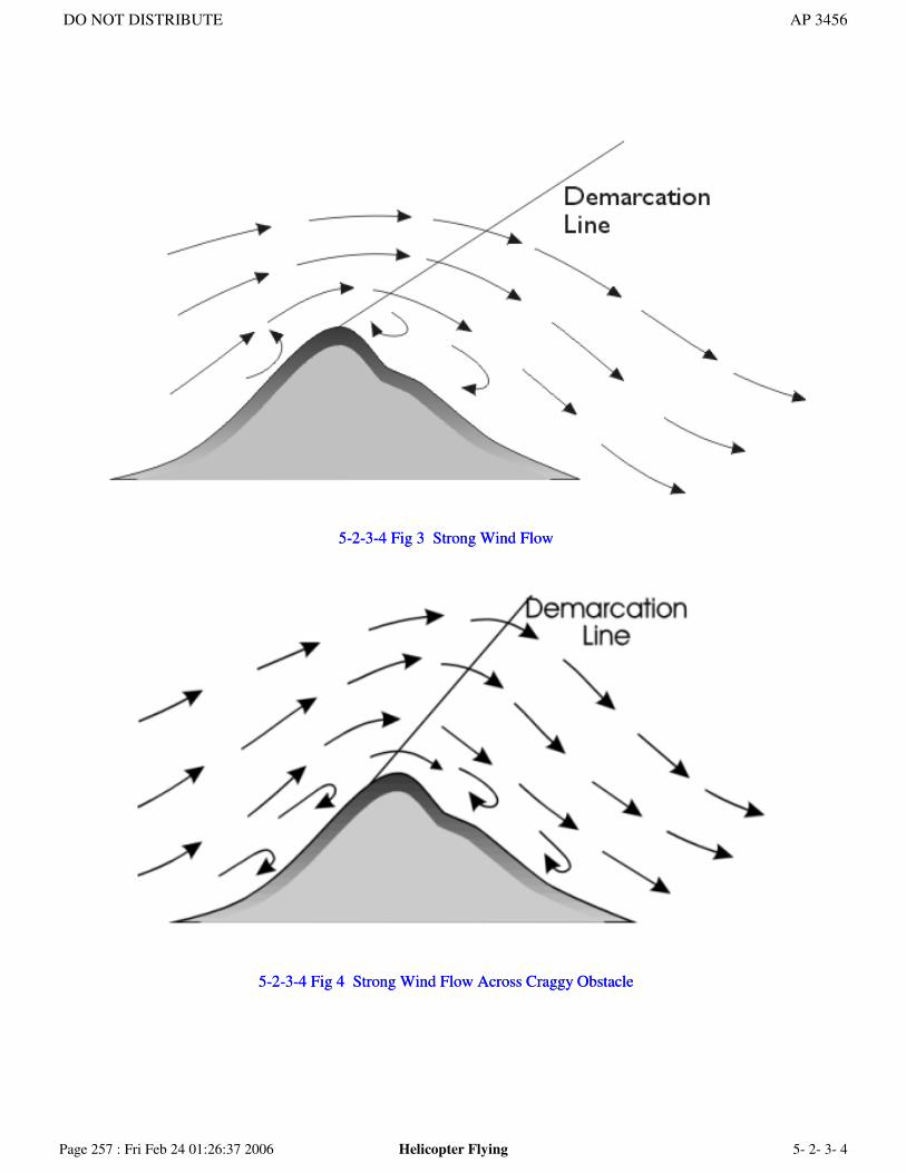
5-2-3-4 Fig 3 Strong Wind Flow
5-2-3-4 Fig 4 Strong Wind Flow Across Craggy Obstacle
5-2-3-4 Fig 3 Strong Wind Flow
5-2-3-4 Fig 4 Strong Wind Flow Across Craggy Obstacle
DO NOT DISTRIBUTE AP 3456
Page 257 : Fri Feb 24 01:26:37 2006 Helicopter Flying 5- 2- 3- 4
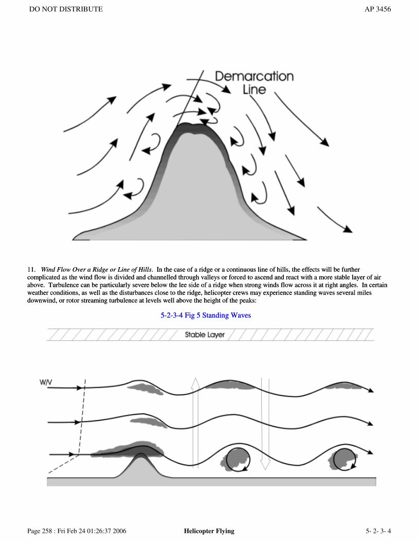
11. Wind Flow Over a Ridge or Line of Hills. In the case of a ridge or a continuous line of hills, the effects will be furthercomplicated as the wind flow is divided and channelled through valleys or forced to ascend and react with a more stable layer of airabove. Turbulence can be particularly severe below the lee side of a ridge when strong winds flow across it at right angles. In certainweather conditions, as well as the disturbances close to the ridge, helicopter crews may experience standing waves several milesdownwind, or rotor streaming turbulence at levels well above the height of the peaks:
5-2-3-4 Fig 5 Standing Waves
DO NOT DISTRIBUTE AP 3456
Page 258 : Fri Feb 24 01:26:37 2006 Helicopter Flying 5- 2- 3- 4

a. Standing waves develop when a deep current of air in which direction is constant and speed increases sharply with height, isforced to rise over a ridge line stretching at or near to the perpendicular across its path. Gravity, and reaction with a layer ofmore stable air above, causes oscillations in the stream which may cause turbulence several miles downwind. This turbulencemay be severe in well developed waves, with reverse winds in the rotor zones beneath the first crests, where roll clouds may alsoform if there is sufficient moisture present (see Fig 5).
b. Rotor streaming requires a strong, shallow, current of air in which speed decreases sharply with height to a stable, slowmoving, layer above. When forced to rise by a ridge or line of hills the air flow decelerates quickly as it ascends, mixesvigorously and tumbles down to cause severe turbulence (see Fig 6). There is no lee wave activity but turbulence may occur inthe layer level with, and possibly up to twice the height of, the ridge line.
5-2-3-4 Fig 6 Rotor Streaming Turbulence
12. Wind Flow Over and Through Valleys. The pattern of wind flow across a valley will depend largely on the strength of the windand the depth of the valley. If the wind is light and the valley shallow, the wind stream will follow the smoothed outline of thedepression, giving rise to gentle up and down draughts (see Fig 7). When the wind is stronger and the valley deeper, the wind mayflow across the top of the feature and curl into it, giving rise to down-draughting on the down-wind side and up-draughting on theup-wind side of the valley (Fig 8).
5-2-3-4 Fig 7 Wind Flow Over Shallow Valley
DO NOT DISTRIBUTE AP 3456
Page 259 : Fri Feb 24 01:26:37 2006 Helicopter Flying 5- 2- 3- 4
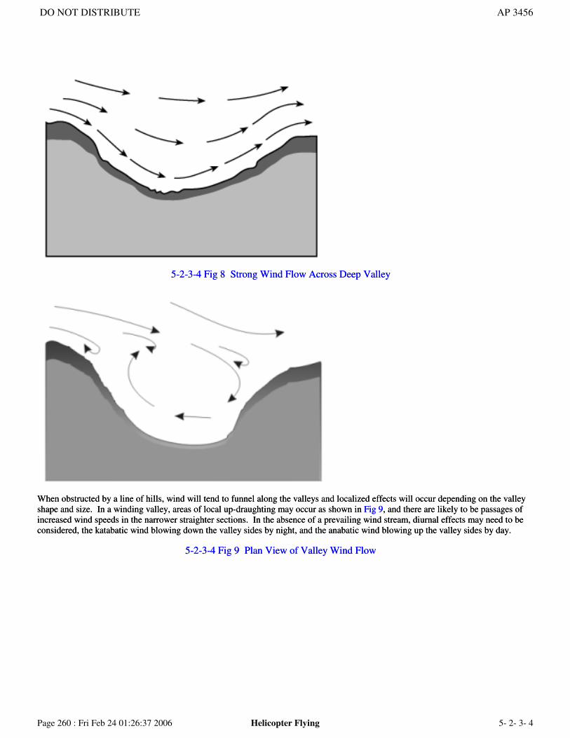
5-2-3-4 Fig 8 Strong Wind Flow Across Deep Valley
When obstructed by a line of hills, wind will tend to funnel along the valleys and localized effects will occur depending on the valleyshape and size. In a winding valley, areas of local up-draughting may occur as shown in Fig 9, and there are likely to be passages ofincreased wind speeds in the narrower straighter sections. In the absence of a prevailing wind stream, diurnal effects may need to beconsidered, the katabatic wind blowing down the valley sides by night, and the anabatic wind blowing up the valley sides by day.
5-2-3-4 Fig 9 Plan View of Valley Wind Flow
DO NOT DISTRIBUTE AP 3456
Page 260 : Fri Feb 24 01:26:37 2006 Helicopter Flying 5- 2- 3- 4

Transit Flying
13. Wide variations in terrain type, weather conditions (particularly wind and temperature), tactical requirements and aircraftperformance considerations preclude the possibility of laying down procedures that can apply in all circumstances. Nevertheless,there are several basic ‘rules’ that may be followed to achieve safe mountain operations
14. Flight Planning. Above all, an appreciation of the nature of the wind in the mountains will be needed for sound planning. Pilotsshould plan to avoid areas of down-draughting and turbulence. Areas of up-draughting may be used to reduce power settings.Pre-flight planning should include a study of:
a. The terrain and features en route including obstacles and power cables. This is particularly significant where power cablesmay be strung across deep valleys.
b. The meteorological conditions, including wind, turbulence, weather, cloud, temperature levels and the risk of icing.
c. Performance planning, including the power margin required, flight envelope considerations, single engine performance andsafety altitudes.
After these factors have been studied a route can be selected. This may be a direct “over the top” line or a valley route. Tacticalconsiderations may of course be over riding, dictating both the route and the height to fly.
15. Escape Routes. Mountain flying operations will frequently require the helicopter to be flown into locations and environmentswhere a change in weather conditions, or a failure of an aircraft service could put the aircraft into a hazardous situation. Themaintenance of an escape route along which the helicopter may be flown safely away from obstacles if it is not possible to continuealong the intended flight path is fundamental to safe mountain flying operations, and should be both a planning consideration and amatter for constant awareness during flight. The nature of the escape route will vary depending on the weather, terrain and type ofaircraft flown. A combination of adequate height above the ground and/or sufficient airspeed and power margin will be required forthe aircraft to be flown away from hazards. Consideration should be given to selecting a flight path where a power-reducing,pedal-assisted turn will facilitate manoeuvre away from obstructions. Passengers and crew must remain secure during those stages offlight where it is not possible to maintain an escape route, typically during, the latter stages of the approach, hover and initial stages ofthe departure.
16. Action When Caught in Severe Down-draughting. In the event that the aircraft is caught in severe down-draughting where it isnot possible to maintain height using full power, the pilot should turn the helicopter to take his escape route. Maximum power shouldbe applied and the helicopter flown at the best rate of climb/angle of climb speed to clear the area. If it is not possible to fly clear ofdown-draughting, the helicopter should be flown towards a flat area where the effect may be less severe. The rate of descent may bereduced by flaring the aircraft and applying any remaining power available.
DO NOT DISTRIBUTE AP 3456
Page 261 : Fri Feb 24 01:26:37 2006 Helicopter Flying 5- 2- 3- 4

17. Retreating Blade Stall. At high speeds and weights at altitude, retreating blade angles of attack will be high. A sharp gust ormanoeuvre could induce retreating blade stall. Pilots should continuously monitor the aircraft’s performance and reduce pitch anglesand airspeed if turbulence is encountered.
18. Engine Emergencies. Pilots of single-engined helicopters should, where possible, fly at a safe height within autorotative rangeof a reasonable landing area. Pilots of twin-engined helicopters should be aware of the maximum altitude that can be maintained inthe event of a single engine failure and plan their operations accordingly.
19. Wind Assessment En Route. During the transit the wind may be assessed continually by reference to and comparison of on-boardnavigational systems (GPS, TANS), smoke, wind lanes and patterns on water, blowing vegetation and cloud formations.
20. Ridge Crossing. The safest technique for crossing ridges will vary depending on the wind strength and whether the crossing is tobe from lee to windward or vice versa. The basic rule is to approach the ridge diagonally to provide the best escape route should thehelicopter be unable to complete the crossing safely. In strong winds crossing from lee to windward should be carried out with ampleclearance above the top of the ridge to avoid down-draughting and turbulence, see para 10. Crossing from windward to lee poses lessobvious hazards; the clearance will be assisted by up-draughts but, if a low cloud base exists, the aircraft may be carried up into cloudeven with minimum power applied. If the crossing is carried out with insufficient clearance the aircraft may encounter turbulence tothe lee of the ridge.
21. Valley Flying. Valley flying constitutes a major part of mountain flying, especially under operational conditions. The followingpoints are relevant to operating in valleys and bowls below the tops of major features:
a. When flying along a valley the aircraft should normally be flown on the up-draughting side to conserve the power margin; theaircraft should be flown close enough to the valley side to allow for a 180° turn escape route, although in strong winds thisrequirement must be balanced against the need to avoid localized terrain turbulence.
b. Weather and tactical considerations may dictate heights at which to fly. Where possible, the aircraft should be flown atsufficient height to allow for free manoeuvre towards an escape route in the event that the selected height or course cannot bemaintained. In strong winds the aircraft will have to be flown below the turbulent layer which may extend down into the valley.
c. In poor weather conditions, with a low cloud base, severe down-draughting or turbulence, it may be safer to fly at low levelclose to the valley floor. Pilots will then need to monitor their flight instruments closely to avoid the dangers of flying to falsehorizons and sloping valley floors. However, flying at low level in a valley should be avoided if an escape route cannot bemaintained.
d. Crews must maintain a continuous watch for pylons on the tops and sides of valleys as a guide to the presence of powercables.
Operating Site Procedures
22. Power Check. Before committing the aircraft to an approach, the pilot should carry out a check to confirm that the power marginavailable is sufficient for the intended operation.
23. High Reconnaissance. A high reconnaissance should be made at a safe height above the site, flown at minimum power speedand normally in a race-track pattern. The following points need to be established:
a. The nature of the terrain surrounding the operating site and the obstacles which will affect possible flight paths.
b. The general wind affecting the site, noting any local features which may cause turbulence, and marked up- ordown-draughting.
c. The approximate height of the site.
d. The size, shape and surrounds of possible landing or hover points.
e. Provisional approach and departure paths.
DO NOT DISTRIBUTE AP 3456
Page 262 : Fri Feb 24 01:26:37 2006 Helicopter Flying 5- 2- 3- 4

f. Escape routes, which should ideally lie within 45° of the approach and departure paths and will normally be down slope.
g. The circuit pattern and a low level reconnaissance plan.
24. Low Reconnaissance. The low reconnaissance is flown at the minimum power speed to pass at low level close to, or over, theintended operating point. If the wind is light, or has already been accurately established, the low reconnaissance may be flown as adummy approach. The proposed approach path should be followed to an overshoot, to confirm the optimum approach, overshoot,departure and escape routes in both elevation and azimuth and the slope and surface of the landing or hover point including anyalternatives. A sudden or marked increase in the power required to maintain the approach is an obvious indication of turbulence. Ifthis occurs in the latter stages of an approach an alternative plan may have to be considered.
25. Localized Wind Finding. Wind has been described as the most important weather factor affecting helicopter mountainoperations. In particular an accurate assessment of the wind affecting the operating point is required to effect a safe approach anddeparture. The reconnaissance must therefore have been preceded by, or should include, this assessment, which may be achieved byone of the following methods:
a. Aircraft Navigational Equipment. If the aircraft is fitted with GPS or Doppler equipment a direct read out of the calculatedwind or Doppler along-and-across velocities may be used.
b. Cloverleaf Drift Pattern. The cloverleaf drift pattern may be used to assess the wind affecting the aircraft. On completion ofthe procedure the aircraft should be pointing into the local wind over a feature (see Fig 10):
(1) Fly (usually on a cardinal heading) at the minimum power speed and at a safe height (200 ft) above the selected point.Note the direction of drift; this will place the wind within a 180° segment.
(2) Turn the aircraft in the direction of drift through 270° and fly across the point at right angles to the previous run. Notethe direction of the drift; this will place the wind within a 90° quadrant.
(3) Turn the aircraft in the direction of drift to fly across the point, bisecting the 90° quadrant. The wind will now be withina 45° arc. Further similar runs may be made; however, usually on the third run the track of the aircraft can be adjusted to flyover the point into wind.
The full procedure is particularly lengthy and is normally used only in the early stages of training. Operationally, if the approximatewind direction is already known, a run across the operating point, adjusting the heading to eliminate drift, will be sufficient todetermine the surface wind direction.
5-2-3-4 Fig 10 Cloverleaf Drift Pattern
DO NOT DISTRIBUTE AP 3456
Page 263 : Fri Feb 24 01:26:37 2006 Helicopter Flying 5- 2- 3- 4

c. Orbit. In light wind conditions an orbit may be flown to assess the wind. The aircraft is flown directly over the operating siteat a safe height. A constant speed turn is flown maintaining the same angle of bank through 360 degrees. On return to the startheading the aircraft will be directly down-wind of the site.
d. Groundspeed/Airspeed/Power Comparison. This method may be used in most situations but is particularly suitable for use inrestricted areas such as valleys and bowls. The aircraft is flown into and out of the area at constant airspeed. A comparisonbetween heading, track and groundspeed into and out of the area will confirm the wind direction and speed. If the power requiredto maintain height is noted, an assessment of the location and strength of areas of up- and down-draughting can be made.
e. Smoke. If available, smoke is probably the best site wind evaluator. It should be used both on the site and on features closeto the site which could have an effect on the wind during any part of the approach or departure. Care must be taken in the use ofpyrotechnics both in their handling inside the aircraft and for their effect on the ground during and after the operation.
f. Cloud. Cloud above an area can provide information on wind direction, strength, and up- or down-draughting affecting thesite.
g. Vegetation. Close examination of the way the wind affects long grass and other vegetation can often give a good indicationof the wind at a site.
h. Water Features. Wind lanes on water surfaces near the site can provide valuable information on wind direction and strength,and ruffled water may be an indication of down-draughting air.
26. The Final Approach Path. The direction of the final approach path will be towards the operating point as near to into wind as
DO NOT DISTRIBUTE AP 3456
Page 264 : Fri Feb 24 01:26:37 2006 Helicopter Flying 5- 2- 3- 4

practicable whilst providing a good escape route.
27. The Circuit. Typically the circuit will be orientated to the final approach path. It will normally be flown at the minimum powerspeed at approximately 200 ft above the operating point. The aim of the circuit is to place the helicopter on the final approach path ata safe speed to start the approach. Pre-landing checks should be completed.
28. The Approach. A constant angle approach should be flown, above the demarcation line, but otherwise as close to normal aspossible. If the onset of turbulence would thereby cause the approach to be too steep, an approach may be offset laterally, further outof wind to give a longer, more shallow descent to the operating site (see Fig 11). The approach should not, however, be so flat thatthe margin for an escape route is reduced during the latter stages, and the angle should, whenever possible, be monitored using thebackdrop technique. At the same time, speed and rate of descent must be watched carefully on the flight instruments.
5-2-3-4 Fig 11 Angle of Approach
29. Overshoot. An overshoot must be initiated if:
a. The helicopter is forced to deviate far from the chosen approach path in azimuth or elevation.
b. A safe power margin cannot be maintained.
c. High rates of descent are encountered at low IAS.
The selected escape route should be flown if a normal overshoot cannot be achieved.
30. Hover and Landing. The helicopter should normally be brought to a slightly higher hover to maintain the aircraft clear ofobstacles until overhead the selected landing point. If the landing point is in turbulent air the helicopter should be brought to thehover over a clear area in smooth or up-draughting air and then manoeuvred carefully to the landing point. Once the final detailedpositioning has been completed the helicopter may be landed using sloping ground techniques. Great care needs to be taken to ensurethat an adequate clearance is maintained between the rotors and rising ground. Passengers should be made aware of the dangers ofreduced rotor clearance with sloping ground.
DO NOT DISTRIBUTE AP 3456
Page 265 : Fri Feb 24 01:26:37 2006 Helicopter Flying 5- 2- 3- 4

31. Take-off. The helicopter should be lifted to the normal hover height and its power margin and take-off path confirmed. Avertical take-off should be initiated to clear the helicopter from near obstacles. When the take-off path is clear a transition should becommenced, preferably over a downslope, and climbing speed achieved before manoeuvring the helicopter further. Flight instrumentsshould be checked to confirm that a positive rate of climb is maintained until clear of all obstacles.
Standard Features
32. There are five standard features that are used in basic mountain flying training. The techniques applied to making an approachand landing at these features provide a sound basis for advanced mountain flying operations. The basic techniques applied to thesefeatures are discussed below.
33. Pinnacles. A standard circuit may be flown to place the helicopter on the final approach path. The final approach path shouldbe offset from the wind to keep the helicopter outside the area of down-draughting and turbulence to the lee of the summit. Anout-of-wind approach will also provide a good escape route away from the feature towards smoother air to the side of the pinnacle(see Fig 12). On the final stages of the approach the helicopter is turned into wind and established in the hover over the landingpoint.
5-2-3-4 Fig 12 Pinnacle Approach
34. Ridges or Saddles. A standard circuit may be flown to place the helicopter on the final approach path. The final approach pathshould be orientated at an angle to the ridge line to provide an escape route away from the feature (see Fig 13). The escape route willnecessarily be towards the lower ground below the top of the ridge in down-draughting air; sufficient height will be needed to fly thehelicopter away from obstacles. On the final stages of the approach the helicopter is turned into wind and established in the hoverover the landing point. A saddle may be approached in the same manner as for a ridge; account will have to be taken of the effect ofthe wind from the higher sides of the saddle.
5-2-3-4 Fig 13 Ridge Approach
DO NOT DISTRIBUTE AP 3456
Page 266 : Fri Feb 24 01:26:37 2006 Helicopter Flying 5- 2- 3- 4
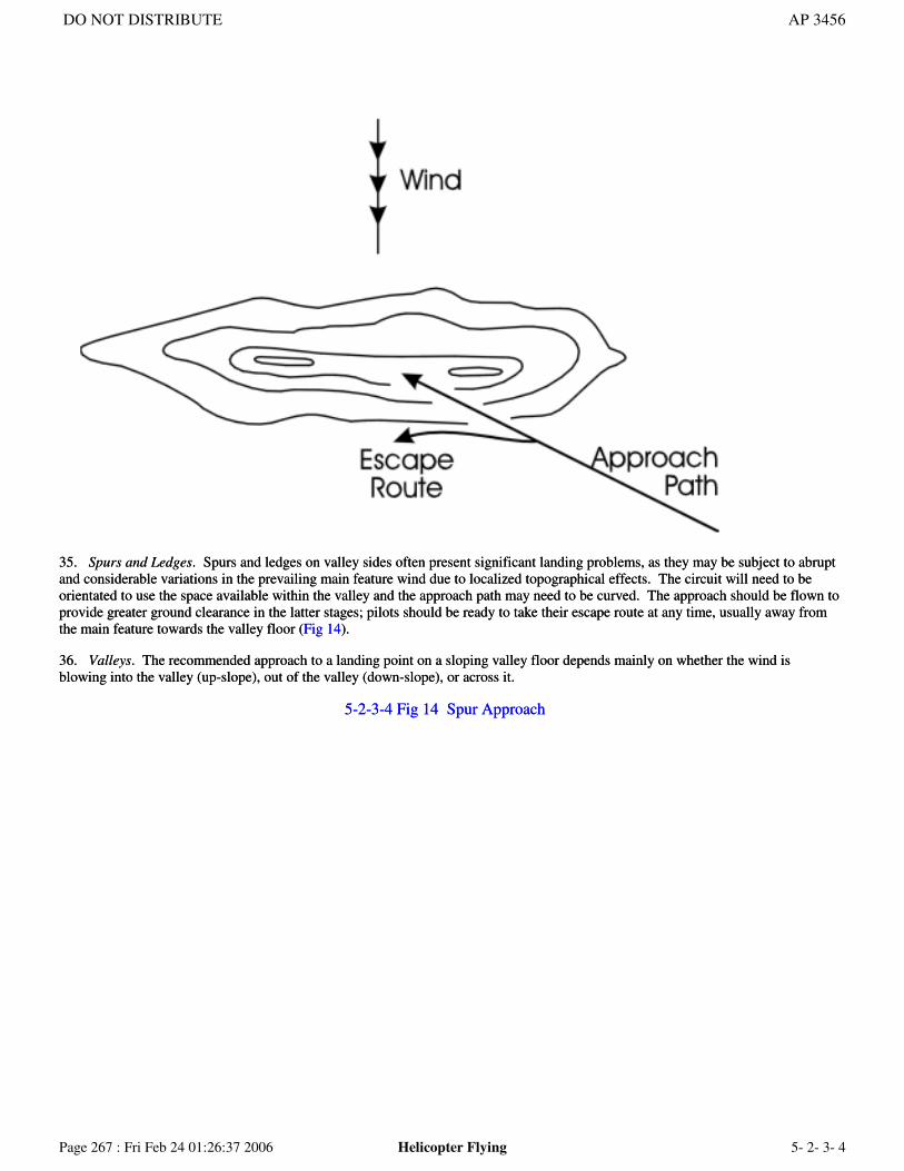
35. Spurs and Ledges. Spurs and ledges on valley sides often present significant landing problems, as they may be subject to abruptand considerable variations in the prevailing main feature wind due to localized topographical effects. The circuit will need to beorientated to use the space available within the valley and the approach path may need to be curved. The approach should be flown toprovide greater ground clearance in the latter stages; pilots should be ready to take their escape route at any time, usually away fromthe main feature towards the valley floor (Fig 14).
36. Valleys. The recommended approach to a landing point on a sloping valley floor depends mainly on whether the wind isblowing into the valley (up-slope), out of the valley (down-slope), or across it.
5-2-3-4 Fig 14 Spur Approach
DO NOT DISTRIBUTE AP 3456
Page 267 : Fri Feb 24 01:26:37 2006 Helicopter Flying 5- 2- 3- 4

a. Up-slope Wind. If the wind is blowing into the valley the circuit will be orientated along its length, with the final approachpath into wind, descending along the downward sloping valley floor to the landing point. The downwind leg should be flown at aconstant altitude with reducing ground clearance as the helicopter is flown towards rising ground. The turn onto the finalapproach path will be determined by the slope of the valley floor to the landing point. If the slope is shallow a normal, level turnmay be made but if the slope is steep the aircraft will have to be descended towards the valley floor in the turn in order to fly anormal approach angle. In light winds the rate of descent must be monitored closely to avoid the possibility of vortex ring. Theescape route (and subsequent take-off and transition) will be directly into wind over descending ground (see Fig 15).
5-2-3-4 Fig 15 Valley Approach - Up-slope Wind
b. Down-slope Wind. The approach to a valley landing site into wind towards rising ground poses, in itself, few problems.
DO NOT DISTRIBUTE AP 3456
Page 268 : Fri Feb 24 01:26:37 2006 Helicopter Flying 5- 2- 3- 4

However, there may be neither a practical escape route nor a subsequent safe take-off path if the slope is severe and the windstrong. In this case an alternative landing point should be considered unless operational considerations are paramount.
c. Across-slope Wind. An approach to a valley landing site with the wind blowing across the valley will normally be made inthe same way as for the wind blowing into the valley, in order to maintain a good escape route. Great care will need to beexercised to keep the rate of descent within limits to avoid vortex ring. If this is not practicable the approach may be madeup-slope. On the final stages of the approach the helicopter is turned into wind and established in the hover.
37. Bowls. Generally, the considerations applicable to a landing point on the floor of a bowl are similar to those for a valley landingsite. However, the close confines of a bowl impose the need for particular attention to the following points when the wind is blowinginto it:
a. Reconnaissance. A detailed assessment of the wind effects within the bowl must be made. The helicopter should be flown atthe minimum power speed around the bowl as high and as close to the sides of the bowl as practicable to assess areas ofturbulence and up- and down-draughting. The direction of flight will be a compromise between the requirements for the pilot tobe close to the obstacles to assess safe clearances, and for a power-reducing, pedal-assisted turn away from obstructions should itbe necessary to take the escape route into the centre of the bowl. Reversing the direction of the reconnaissance will often give agreater overall view of the feature. Further lower orbits around the bowl should be flown at a suitable height until it has beenestablished that a safe approach may be made to the landing point. Speed may be reduced once it has been assessed that it is safeto do so.
b. Approach. The final approach path will be commenced from a suitable height above the landing point as a descending curvestarting from the mouth of the bowl, flying the helicopter forward and down around the sides of the bowl until a normal sightpicture approach can be completed into wind (see Fig 16).
5-2-3-4 Fig 16 Bowl Approach
c. References. There will be no natural horizontal references in the bowl and the floor of the bowl may be sloping. Thetendency will be for the pilot to reduce airspeed in an attempt to maintain a reasonable groundspeed whilst flying downwind andto climb as he approaches rising ground towards the back of the bowl. It is essential that the flight instruments are monitoredcarefully to assess the helicopter’s attitude and to maintain a minimum safe airspeed for manoeuvring until the helicopter isestablished in smooth or up-draughting air. The forward and down-curving approach may be achieved by selecting markers
DO NOT DISTRIBUTE AP 3456
Page 269 : Fri Feb 24 01:26:38 2006 Helicopter Flying 5- 2- 3- 4

along the proposed path and flying the helicopter towards them until the landing point is visible.
d. Escape Route. The escape route will be to turn the aircraft away from obstructions towards the centre and out of the bowl.Because the helicopter will be flown close to the sides of the bowl and with minimal vertical clearance, it is essential thatsufficient airspeed be maintained to manoeuvre the helicopter away from obstructions before it can be allowed to descend. Theminimum speed will vary, depending on the type of helicopter, between 20 and 40 kts.
Advanced Techniques
38. Although the standard and simplest helicopter approach is made into wind, there may be occasions when tactical considerationsdictate the use of modified, more advanced techniques. The deployment of troops or equipment may require the helicopter to behovered close to a cliff face below the tops of the surrounding features, or it may be important to avoid being seen above the sky line.In the latter case, if a final approach from above the sky line is inevitable, the reconnaissance should be carried out whilst keeping thehelicopter concealed, and the aircraft only climbed to intercept a normal approach path to avoid down-draughting air in the finalstages. The departure too would need to be modified to achieve a lower profile on take-off until it became safe to descend againbelow the sky line. Two advanced approach techniques can be used:
a. Up-draughting Approach. The up-draughting approach is particularly applicable for an approach to a landing point on aridge line or saddle; indeed, with experience, it may be the preferred approach under normal circumstances. The helicopter isflown at low level in the up-draughting air on the windward side of the ridge. As the landing point is approached thegroundspeed is reduced and the aircraft turned into wind and established in the hover. This technique can be adapted for otherfeatures (such as a pinnacle). The helicopter is established flying into wind to the side, either level with or just below the top, ofthe feature. The helicopter is climbed in the up-draughting air until abeam the landing point; it is then manoeuvred across the topof the feature towards the landing point.
b. Level Approach. A level approach will normally be made when the helicopter is required to be brought to the hover belowthe top of the major feature. The helicopter is flown close to the cliff face, level with the operating point. As the operating pointis approached the groundspeed is reduced gradually and the hover established. This technique has several advantages:
(1) The approach is easy to fly with good references close to the helicopter.
(2) The approach requires no more power than is required for the hover because no additional power is required to stop a rateof descent. This is particularly applicable if the helicopter is to be hovered in down-draughting air.
(3) A good escape route is maintained throughout the operation.
Winter Operations - Day
39. There are several additional hazards that may be encountered whilst flying in mountainous terrain during winter. These areassociated with the cold environment, the volatility of the weather, and in particular the effect that snow can have on visualreferences. In all cases the requirement to maintain a good escape route is paramount. The most significant hazards are noted below:
a. Weather. Bad weather can arrive suddenly in the mountains. In winter, severe conditions of low cloud, hail, snow, and poorvisibility may be encountered with little warning.
b. Icing. The dangers of engine, airframe, and control icing are significant.
c. White-out. White-out conditions are particularly hazardous as all reliable external references may be lost suddenly, andwithout warning; frequent reference to flight instruments is essential. The radar altimeter should be used as the primary heightreference. The low warning bug should be selected at just below the minimum safe transit height to provide a warning of risingground. The escape route must be taken early to clear white-out conditions, and an alternative route selected.
d. Glare. On bright days reflected sunlight may cause a blinding glare. Crews must ensure that their visors are clean and usetheir tinted visors to prevent snow blindness.
40. Snow Landing. The downwash of the helicopter in the hover will blow loose snow causing it to recirculate and envelop the
DO NOT DISTRIBUTE AP 3456
Page 270 : Fri Feb 24 01:26:38 2006 Helicopter Flying 5- 2- 3- 4
helicopter. This may create white-out conditions, making a safe landing impossible unless crews are prepared by ensuring thatadequate hover references are available before committing themselves to a landing. The following snow landing techniques arerecommended:
a. Hover Reference Marker. The landing site must be reconnoitred carefully to ensure that it is free from obstructions. Anobject (such as a small tree) is selected as a hover reference marker (HRM) which will remain visible to the crew when white-outoccurs. The approach is made to a hover, at the normal hover height, to place the HRM in the 2 o’clock position close to thehelicopter. The pilot must be prepared for the snow cloud to envelop the helicopter. Once established in the hover next to theHRM a careful landing is carried out, allowing the helicopter to sink into the snow and settle, but avoiding obstructions beneaththe snow that might cause damage. Once the helicopter has settled, gentle lateral cyclic movement may be used to allow it tosettle fully. Throughout the landing the pilot must be prepared to re-establish the hover as soon as a mislanding is evident.
b. High Hover. If an HRM is not available, the top layers of snow will have to be removed to reveal sufficient references for alanding to be made. The helicopter is brought to a high hover, clear of blowing snow, over the landing point. Forward andlateral reference markers are selected to hold position, and the helicopter’s downwash is used to blow the snow clear. Once theinitial blowing snow has been cleared the hover height is reduced by 15-20 ft and again the snow cleared. This procedure iscontinued until an object that can be used as a hover reference marker is visible. The landing is then completed as above.
c. Zero Speed Landing. Once the nature of the terrain beneath the snow is known to be suitable, a zero speed landing may bemade. It is not advisable to attempt a running landing on snow covered surfaces.
41. Snow Take-off. During the initial stages of the take-off it is important that the helicopter rises evenly from the ground. This canbe achieved by small applications of yaw and cyclic control to break the grip of frozen snow. As the helicopter breaks from theground the hover attitude is established and a vertical instrument take-off continued without delay to clear the helicopter from blowingsnow. A retractable undercarriage should be cycled to clear any wet snow to prevent freezing of the undercarriage and brakes. Arunning take-off on a snow covered surface is not advisable.
Winter Operations - Night
42. General. The flying techniques required for night operations in snow (with or without night vision goggles (NVG)) are anextension of the basic day flying techniques. Even so, the difficulties and hazards associated with operations in snow are exacerbatedat night. When operating at night in snow consider the following:
a. Overshoot. The correct overshoot technique is as important as that for landing. If in doubt, overshoot early. Note also thecomments regarding blowing snow in c. below.
b. Navigation. Ambient weather conditions, cloudbase, visibility and precipitation are more difficult to assess at night, with orwithout NVG assistance. Even with NVG assistance, navigation across wide expanses of unbroken snow is more complicatedthan in daylight and should be avoided; routes should be selected to remain below the tree line. Assessing the nature of theterrain below the aircraft, or below the snow, is also harder than in daylight. As with day flying the safest method of landing isfrom the hover.
c. Use of NVG. Depth perception is reduced when using NVG. When operating with NVG in snow a constant and careful scanis required of the radar altimeter and the flight instruments to check the aircraft attitude and height. Good crew cooperation isparamount.
d. Hazards of Blowing Snow. Recirculation of blowing snow will present even greater problems in the hover than in daylight,therefore the selection of good hover references with strong contrast is essential. Suitable references may be supplied by treestumps, bushes, dark rocks or suitable light sources. As the hover reference will be inside the rotor disc on landing the pilot mustbe certain of it's height. If a NATO 'T' is available then consider using the 'T' base light as a lateral marker. An NVG compatibleNATO 'T' allows the pilot to remain operating with NVG assistance; a non-NVG compatible 'T', dependent on ambient lightconditions, may not. Time in the hover should be kept to a minimum, and take-off and approach made as if by day. Applying asignificant amount of pitch to the rotor disc for a period before lifting will often clear away the loose snow and reducerecirculation in the hover. Disorientation is an even greater hazard during an overshoot at night. The non-handling pilot shouldmonitor all approaches closely and be prepared to call for an overshoot, or take control. If references are lost at any stage of anapproach or landing, overshoot early and be prepared for an immediate transfer to instruments with a vertical climb at maximum
DO NOT DISTRIBUTE AP 3456
Page 271 : Fri Feb 24 01:26:38 2006 Helicopter Flying 5- 2- 3- 4

power until clear of the snow cloud and able to establish visual flight with suitable external references. A sudden entry into acloud of blowing snow, with complete loss of external references, is extremely disorientating.
e. Lighting. Snow intensifies and reflects light, whether NVG-compatible IR lighting or white light. This intensification of lighthinders the use of aircraft external lighting in a snow cloud. Each external light source fitted to a helicopter has its own meritsbut there is a limit to the assistance that it can give. Experimentation with the external lighting system, and aids available, willdetermine the most appropriate mix to use for the conditions being experienced. If using NVG then careful use of availablelighting on the ground can be beneficial. Day flares are normally far too bright for NVG operations whilst Arctic SmokeGrenades tend to sink into the snow and leave a stain, which is visible on NVG but is easily lost in the snow cloud in the finalstages of an approach. 'Cylume' chemical light sticks can offer limited hover references if they are thrown from the aircraftoverhead a suitable landing point, however they must be attached to a suitable stick or pole to stop them sinking into the snow.The best approach and hover reference is provided by troops huddled together with a suitable white light source. Such troopsmust be suitably briefed and be aware of the danger to themselves, and to the aircraft, of sloping ground. Any white light sourceat a landing point must not be too bright and must be directed away from the aircraft or it will have the detrimental effect ofreducing the gain of the NVG thus reducing the effective visibility of the pilot. If the aircraft lights are to be used, whether IR orwhite light, it is recommended that they be turned off prior to the aircraft being engulfed by the snow cloud. Should aircraftexternal lights, especially high intensity landing lamps, be left illuminated in a snow cloud, the snow crystals will reflect so muchlight that the NVG gain is reduced, effectively limiting visibility to the snow cloud only. The lighting systems of individualhelicopters allow many combinations and permutations. Accordingly, captains should consider and brief the responsibilities forlight switching before any approach.
43. External Loads. The basic techniques for operating with underslung loads in snow conditions are the same day or night.However, the difficulties and hazards associated with operations in snow are exacerbated at night. Underslung loads normally requireaccurate position adjustments within the ground cushion; however, hovering in the ground cushion can rapidly lead to white-out.White-out can sometimes be dispersed by a short period in the high hover.
a. Pick-up. The aircraft is lifted to the hover using a prominent hover reference, the hover height may have to be between 30 - 80ft agl dependent on snow conditions. After the white-out has been allowed to dissipate the aircraft is manoeuvred to overhead theload, with the pilot maintaining good visual references. Clearly defined lateral and forward hover references, combined withthose from the radar altimeter are essential to maintain an accurate hover. Once sufficient visibility has been achieved the aircraftmay descend, in steps if required, and the load attached. Consideration should be given to using a length of strop or strops whichwill allow a higher hover and expedite the process. When the load clears the ground the radar altimeter height should be noted.At this stage there is a significant chance that the increased downwash will induce further recirculating snow; as at any stage inthe pick up, if references are lost the pilot must immediately transfer his scan to the flight instruments and climb vertically clearof the snow cloud.
b. Drop off. A normal approach should be flown to a higher than normal hover some distance short of the drop point, aiming tokeep the snow cloud below the aircraft whilst keeping the landing point and marshallers in sight. As the snow cloud begins toclear, the aircraft should be marshalled forward and down to place the load on the ground. No attempt should be made to placethe load on the ground using a zero speed technique in recirculating snow.
c. Protection. Snow or ice will increase the weight of the load. The helicopter crewman is especially subject to the chill effect ofthe slipstream and should wear face and eye protection, such as ski-goggles. The hook-up team needs substantial protectiveclothing, and static build-up is far greater at low temperatures. If possible the load should be attached from inside the aircraftusing the 'shepherds crook' load attachment pole.
Formation Flying
44. Day or night tactical formation flying in snow conditions can be conducted using the normal procedures laid down in aircraftSOPs. The following additional points should be considered when operating in a winter environment:
a. Configuration. Formation size and composition will require modification to cater for the conditions. A formation landing inrecirculating snow conditions can be extremely difficult and potentially hazardous.
b. Camouflage. Arctic camouflage is very effective in the snow, even above the tree line; it may be necessary to reduceinter-formation distances.
DO NOT DISTRIBUTE AP 3456
Page 272 : Fri Feb 24 01:26:38 2006 Helicopter Flying 5- 2- 3- 4
c. Obstacle Clearance. Each aircraft captain is responsible for his own terrain clearance and care must be taken not to fly intohidden features, such as snow covered ridges, as a result of fixation on the other formation aircraft.
d. Escape Route Brief. During transit flying in mountainous terrain the formation leader should consider briefing his formationescape route to allow other aircraft to position accordingly.
Tandem Rotor Operations
45. In general, the principles of mountain flying for tandem rotor helicopters are the same as for single main rotor aircraft. Theenhanced ability to operate out of wind may be a significant advantage because the pilot will have a greater choice of approach anddeparture paths to avoid turbulent air.
46. Differential Lift. Pilots should be aware of the dangers of flying tandem rotor helicopters in environments where the two rotorsmay be experiencing significantly different air flows causing differential lift and potential control problems. Hovering into wind closeto the edge of a ridge or a pinnacle, where the front rotor may be in up-draughting air and the rear rotor in level or (in extreme cases)down-draughting air, should be avoided.
47. Landing Point. When considering the choice of landing point and landing direction crews will need to take into account thenature of the ground beneath the ramp for loading and unloading of troops and cargo.
Conclusions
48. Helicopter flying in mountainous terrain poses many problems. Most of these problems may be overcome by detailed planningand a knowledge of the wind and weather. The application of mountain flying techniques to tactical and search and rescue operationsdepends on confidence derived from thorough and effective training. Most importantly a knowledge of helicopter and crewlimitations and the maintenance of a good escape route is essential for safe operations.
Helicopter Flying
Chapter 5 - Shipboard Operations
Introduction
1. The procedures to be followed when operating helicopters from ships are laid down in Chap 8 of Supplement No 1 to JSP 3. Theaim of this chapter is to outline the general procedures and the particular hazards that may be expected with shipboard operations.
Equipment
2. All helicopters which are to remain onboard ship are to carry the following equipment, or arrangements are to be made for it to beheld onboard:
a. Blade folding gear.
b. Covers.
c. Control locks.
d. Anti-corrosion equipment.
e. Special-to-type lashings.
f. Wheels.
g. Gust locks for tail rotors.
DO NOT DISTRIBUTE AP 3456
Page 273 : Fri Feb 24 01:26:38 2006 Helicopter Flying 5- 2- 3- 5

h. Steering arm (where applicable).
GENERAL FLYING PROCEDURES
General
3. Before operating from ships, helicopter pilots unfamiliar with deck operations are normally to be briefed onboard the ship by amember of the ship’s staff and carry out deck landings accompanied by a deck qualified pilot. Experienced helicopter pilots, who areunable to have a briefing onboard, may be permitted by the larger ships to land in daylight and in moderate sea states. Newlyqualified helicopter pilots must carry out a minimum of four deck landings under dual instruction before they make a solo decklanding.
4. Specific procedures when operating with an Aircraft Carrier are dealt with in the second part of this chapter.
Joining Procedure
5. Helicopters normally approach a Commando or Assault Ship under the control of the ship’s Operations Room (callsignHOMER), changing frequency to Flying Control (FLYCO) when they become visual with the ship. When operating from other ships,the pilot should contact the Helicopter Controller (HC) at 10 miles or when visual. When giving the pilot permission to join, FLYCOwill pass as much information as possible, such as: altimeter setting, the ship’s course, the relative wind, landing spot number and anyobstructions.
6. Helicopters Landing Onboard with Stores or Armament. Because of the danger of possible radiation hazard (RADHAZ)affecting his stores or armament, the pilot, on joining, is to warn the ship of any stores or armament being carried. In the case ofarmament, the pilot is to report its type, whether it has misfired and if so, when he last tried to fire it. It should be remembered thathelicopter flares ground illuminating are particularly sensitive to RADHAZ.
Circuit Procedure
7. With a relative wind from forward of the ship’s beam, the normal procedure is a left-hand circuit on the port side of the ship. (Itshould be noted that there are exceptions such as the Landing Ship Tank (LST(H)), where a right-hand circuit is the normal method ofapproach). The circuit height is 200 ft and when down-wind the pilot should check brakes ON and wheel locks IN. It is necessary toanticipate the ship’s movement by turning early from down-wind to base leg, and “Finals” (with gear down as appropriate) is thencalled. The circuit should be planned so that there is a straight approach of 150 yards from astern. Pilots then fly up the port side ofthe ship until abreast of the landing position.
8. When making the final approach, allowance should be made for the height of the deck above sea level and it should beremembered that turbulence can be expected. If the wind is from astern, FLYCO or the FDO will pass an alternative circuit procedureto the pilot by radio. Two typical circuit patterns are illustrated at Fig 1.
9. If an overshoot is necessary, instructions, including direction of overshoot, are passed by radio and the Director signals “WaveOff”. It should be noted that “Wave Off” is mandatory.
10. With an unserviceable radio, the pilot should join the circuit with care and fly slowly up the port side of the flight deck until heis visible to the Director, who then signals him to land.
5-2-3-5 Fig 1 Helicopter Circuit Patterns
DO NOT DISTRIBUTE AP 3456
Page 274 : Fri Feb 24 01:26:38 2006 Helicopter Flying 5- 2- 3- 5

Landing Procedure
11. From a position 15 yards to port of the ship the pilot is marshalled on to his landing spot. Turbulence may be experienced atsome landing spots and may be severe in the case of a beam wind.
12. There are many obstacles such as masts and aerials which may be difficult to see; it is essential, therefore, that extreme care istaken and the marshaller’s signals adhered to.
13. Shutdown. After a helicopter has landed and it is known that it is staying down, the Director signals “In Chocks” as soon as thepilot indicates that it is clear to do so. It is important that rotors are not disengaged or engines shut down before this signal is given asthe ship may alter course and affect the relative wind.
14. Lashing. On all RN ships deck crews will lash the aircraft down with the rotors running; pilots should be aware of this and othershutdown procedures by studying the appropriate SOPs.
Start-up and Launch Procedure
15. A start-up and launch procedure is shown in Table 1.
Table 1 - A Start-up and Launch Procedure
Time Order System Action
L minus 15 (20) mins(see Notes 1 and 2)
“Aircrew manaircraft”
Broadcastthroughout the
Off lashings and cuffs when aircraftmanned (unless otherwise ordered).
DO NOT DISTRIBUTE AP 3456
Page 275 : Fri Feb 24 01:26:38 2006 Helicopter Flying 5- 2- 3- 5
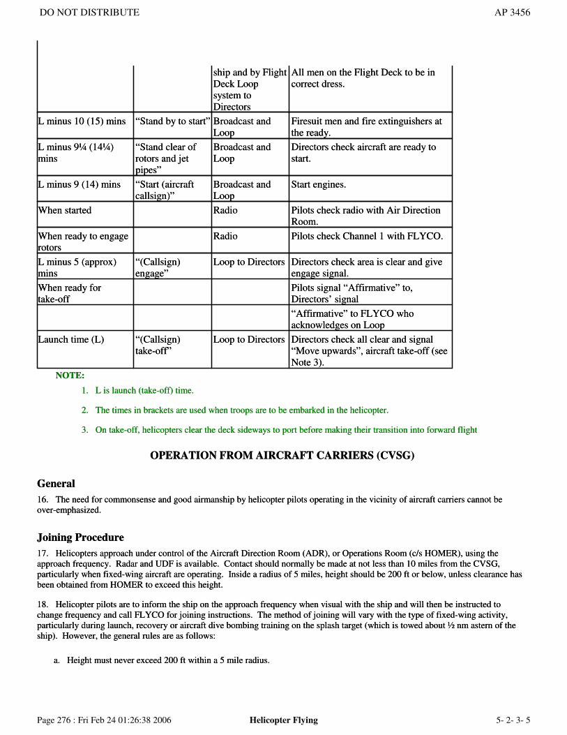
ship and by FlightDeck Loopsystem toDirectors
All men on the Flight Deck to be incorrect dress.
L minus 10 (15) mins “Stand by to start” Broadcast andLoop
Firesuit men and fire extinguishers atthe ready.
L minus 9¼ (14¼)mins
“Stand clear ofrotors and jetpipes”
Broadcast andLoop
Directors check aircraft are ready tostart.
L minus 9 (14) mins “Start (aircraftcallsign)”
Broadcast andLoop
Start engines.
When started Radio Pilots check radio with Air DirectionRoom.
When ready to engagerotors
Radio Pilots check Channel 1 with FLYCO.
L minus 5 (approx)mins
“(Callsign)engage”
Loop to Directors Directors check area is clear and giveengage signal.
When ready fortake-off
Pilots signal “Affirmative” to,Directors’ signal
“Affirmative” to FLYCO whoacknowledges on Loop
Launch time (L) “(Callsign)take-off”
Loop to Directors Directors check all clear and signal“Move upwards”, aircraft take-off (seeNote 3).
NOTE:
1. L is launch (take-off) time.
2. The times in brackets are used when troops are to be embarked in the helicopter.
3. On take-off, helicopters clear the deck sideways to port before making their transition into forward flight
OPERATION FROM AIRCRAFT CARRIERS (CVSG)
General
16. The need for commonsense and good airmanship by helicopter pilots operating in the vicinity of aircraft carriers cannot beover-emphasized.
Joining Procedure
17. Helicopters approach under control of the Aircraft Direction Room (ADR), or Operations Room (c/s HOMER), using theapproach frequency. Radar and UDF is available. Contact should normally be made at not less than 10 miles from the CVSG,particularly when fixed-wing aircraft are operating. Inside a radius of 5 miles, height should be 200 ft or below, unless clearance hasbeen obtained from HOMER to exceed this height.
18. Helicopter pilots are to inform the ship on the approach frequency when visual with the ship and will then be instructed tochange frequency and call FLYCO for joining instructions. The method of joining will vary with the type of fixed-wing activity,particularly during launch, recovery or aircraft dive bombing training on the splash target (which is towed about ½ nm astern of theship). However, the general rules are as follows:
a. Height must never exceed 200 ft within a 5 mile radius.
DO NOT DISTRIBUTE AP 3456
Page 276 : Fri Feb 24 01:26:38 2006 Helicopter Flying 5- 2- 3- 5

b. The sector 45° either side of the bow or stern, out to a radius of 1 mile, must not be entered without clearance by FLYCO.Clearance to cross the bow must be obtained.
c. When the splash target is in use, approaches should begin from forward of the port beam, and should not extend abaft thebeam. Attempts should not be made to close nearer than 5 miles unless in radio contact with FLYCO, or, if this is not possible,with the ship on the approach frequency.
19. The following information is passed by FLYCO:
a. Ship’s course for landing or Designated Flying Course (DFC).
b. Relative wind.
c. Landing spot or waiting position.
d. Altimeter setting (QFE).
e. Any additional precautionary instructions.
20. FLYCO is manned by Lt Cdr Flying who is Cdr (Air)’s deputy; he is responsible for the safety of all persons and aircraft on theFlight Deck and in the immediate vicinity of the ship. The Flight Deck Directors take their instructions from him on the Loop andtheir signals are mandatory. This particularly applies to engaging/stopping rotors. Captains of aircraft retain their responsibility forthe safety of their aircraft but it is important that they realize the difference between an ordinary marshaller and a Flight DeckDirector. (Marshallers wear yellow surcoats).
Waiting Positions
21. There are two waiting positions for helicopters during fixed-wing flying; these are:
a. Port Wait - circuit at 200 ft, remaining ¼ nm clear of ship.
b. Starboard Wait - circuit at 200 ft on the starboard beam, remaining ¼ nm clear of ship.
Circuit Procedure
22. Normally by day, straight-in approaches are made from astern. Pilots then fly up the port side of the ship and when abreast thenominated spot are marshalled by the Flight Deck Directors.
23. Normally helicopters land facing forwards but in a strong wind are marshalled facing into wind; should the relative wind be fromastern, approaches are; made from the bow and helicopters land facing astern.
24. For various reasons a CVSG is seldom able to provide the most favourable relative wind for helicopter launch or recovery andpilots should exercise due caution.
25. Radiation Hazard. The following points should be borne in mind when operating in the vicinity of ships:
a. Radhaz for the type 909 radar.
b. Single sideband HF must be switched off when within half a mile of a CVSG.
A complete list of items occasioning RADHAZ is given in CVSG Handbook - BR 766C Vol 5.
Start-up and Launch Procedure
26. Start-up and launch procedures are similar to those shown in the table at para 15. On take-off, helicopters clear the deck as soon
DO NOT DISTRIBUTE AP 3456
Page 277 : Fri Feb 24 01:26:38 2006 Helicopter Flying 5- 2- 3- 5

as possible in the direction indicated by the marshaller before making a transition into forward flight.
Helicopter Flying
Chapter 6 - Search and Rescue (SAR) Operations
Introduction
1. The responsibility for Search and Rescue (SAR) and the organization involved is covered in AP 3456, Vol 6, Pt 3, Sect 1, Ch 1,and ATP-10(B). Search techniques and the majority of rescue methods are also contained in these publications; however, thischapter provides an introduction to specific helicopter aspects of SAR operations.
Helicopter SAR Standby Procedure
2. During many years of operating SAR helicopters, the RAF has developed a pattern of procedure for crews operating in this role.The following is offered as a guide for the procedure at Flight or Unit level:
a. On taking over standby duties the pilot checks the Form 700 noting fuel states, serviceability and hours available. He makesan external and internal check of the 1st and 2nd standby helicopters. The winch operator and winchman make a physical checkof all rescue and safety equipment in the 1st and 2nd standby helicopters and of all the additional items of equipment that may becarried. The navigator/co-pilot checks the navigation equipment and ensures that it is set up correctly. The crew study themeteorological situation and information and note any navigation warnings, Royal flights etc. A continuation flying trainingprogramme is planned for the period of standby.
b. In the event of an emergency call the groundcrew prepare the helicopter for take-off. The navigator/co-pilot takes thetelephone call and fills in a proforma of the details. He indicates to the pilot if an immediate start-up is required and informs thewinchman of any additional items of equipment necessary. The crew flight plan as necessary. The pilot starts up the helicopterand during the sortie uses his “Rescue Helicopter” callsign.
c. The Flight Operations Room telephone is manned by available aircrew or groundcrew and the necessary authorities areinformed of the operational call. The second standby crew is called in if necessary. All telephone messages, R/T calls and actiontaken is entered in the appropriate log.
d. On return from the sortie the pilot ensures that the helicopter is serviced and refuelled as soon as possible. The winchmanensures that the rescue and safety equipment is brought back up to scale. The navigator/co-pilot telephones the AeronauticalRescue Co-ordination Centre (ARCC) giving details of the sortie.
Flight Planning
3. In addition to the normal flight planning, details are required for the fuel load, weight centre of gravity and winchingperformance. Although crews normally flight plan for possible emergency calls as soon as they commence standby duty, the diversityof helicopter operations may require special flight planning - particularly for long range sorties; this aspect of flight preparationcannot be over-emphasized. During the actual flight, continual checks must be made on fuel consumption, weather conditions and thepossible effects on aircraft weight, CG and range, before and after survivors are winched aboard.
Use of Radio
4. Whenever possible, the main UHF set should be used with the function switch set to “T/R & G”. This enables the Guardfrequency of 243 MHz to be monitored so that any emergency calls on this frequency can be intercepted. On training sorties, whenthe helicopter is on airborne standby, and whenever a helicopter is flown over water, periodic ‘Ops Normal’ calls are made to theoperating base, eg “Chopper 99 crossing coast outbound Croyde Bay, ‘Ops Normal’ call in 15 minutes”.
Crossing Coast Check
DO NOT DISTRIBUTE AP 3456
Page 278 : Fri Feb 24 01:26:38 2006 Helicopter Flying 5- 2- 3- 6
5. Prior to crossing the coast outbound, pilots should complete a check that includes:
a. Flotation equipment - armed.
b. Console switches.
c. Warning lights.
d. Temperatures and pressures.
e. Fuel.
f. Harnesses.
g. Cockpit and cabin doors (normally open).
h. Safety equipment worn by crews.
i. Compasses.
j. Altimeters, including radar altimeter bug.
k. Navigation equipment.
l. Radio check call.
Hovering and Winching Performance Check
6. When a target or survivor is sighted, and prior to coming to the hover, it is essential that a power check is carried out at theappropriate speed specified in the ODM for the aircraft. The power required for straight and level flight at this speed is thencompared with the total power permitted for use. The margin between the two figures will then indicate to the pilot what hiswinching performance is likely to be.
Standard Winching Circuit
7. The full winching circuit is normally only practised under training conditions. However, the procedure, checks and calls are usedon operational sorties even if the actual position when they are used has to be modified. All turns are normally made to the right sothat the pilot and crew members can keep the target in sight. During the last part of the run-up to the hover the pilot will lose sight ofthe target and from then on he has to rely on verbal guidance given to him by the winch operator. The winch operator, by usingstandard patter, can continue to direct the pilot to overhead the target. The pilot, by making the corrections given by the winchoperator, can keep the helicopter overhead the target whilst the actual winch operating is performed. All forms of helicopter winchinginvolve team work between the pilot, winch operator and winchman. It is essential that standard procedures and patter are used toensure safety and to avoid confusion.
Wet Winching
8. Methods. The actual methods of winching are described in detail in AP 3456, Vol 6, Pt 3, Sect 1, Ch 3 and consist of:
a. The single lift.
b. The double lift.
c. The grabbit hook double lift.
d. The extension lead double lift.
e. The stretcher lift.
DO NOT DISTRIBUTE AP 3456
Page 279 : Fri Feb 24 01:26:38 2006 Helicopter Flying 5- 2- 3- 6
f. The Hi-line transfer.
Deck Winching
9. Deck winching means winching from any type of vessel. It is distinct from dry winching where the survivor is on land, or fromwet winching where the survivor is in the water. Standard winching procedure and patter are used as far as possible with thevariations necessary for the different conditions that may be encountered. The vessel may be of any size from a canoe to an oceanliner, travelling under way, drifting, or stationary; it could be steady in a calm sea or pitching, rolling and yawing many feet in galeconditions. The winching area could be perfectly clear and flat or it could be a mass of masts, wires and other obstructions.Communications with the vessel may or may not be possible.
10. On arrival at the vessel a general survey is made to note the obstructions and decide on the best winching area. This should be aslarge as possible, clear of obstructions, with a clear entry and exit line and with a part of the vessel in view of the pilot from thewinching position. Depending on the wind direction and the sea state it must be decided what is the best heading for the vessel tosteer. Where possible the vessel should head 30° to 40° to the right of the wind heading, with the helicopter heading into the wind:the winching area is then in view of the winch operator.
11. The speed of the vessel will depend on the sea state, wind and the need to maintain steerage way; about 5 to 10 kt is mostsuitable. In wind conditions over 20 kt with a high sea it is possible that small vessels will have difficulty heading into wind. If thevessel heads down-wind at about 5 kt it is possible that there will be less difficulty; the helicopter can then winch, heading into windfrom the bows of the vessel. The headwind component for the helicopter will be the wind speed less the speed of the vessel.
12. Communications with the vessel can be made direct by UHF, VHF, Aldis or hand signals, or it may be possible to use a radiolink with a ground station or escort aircraft. Information given to the vessel must include the intended winching area and heading andspeed for the vessel to adopt.
13. On the run-in at about 30m the pilot yaws the helicopter into wind and moves slightly crabwise to the winching area. From thispoint on the run-in, and for the rest of the time this method of winching is in progress, the winch operator will relate all corrections tothe fore-and-aft line of the vessel, ie “Forward 5” will mean a movement of five winching units (a winching unit is a distanceestimated by the winch operator, and is taken to be between 2-3 metres) along the fore-and-aft line of the vessel towards the bows.Should the pilot for any reason lose sight of the vessel, he is to inform the winch operator. The winch operator then gives correctionsin relation to the fore-and-aft line of the helicopter until such time as the pilot is again in visual contact with the vessel. In the case ofa very small vessel the pilot is unlikely to see any part of it; the winch operator then gives all corrections in relation to the fore-and-aftline of the helicopter as for normal winching. It must be positively understood between the pilot and the winch operator whichmethod of correction is to be used before the winching commences.
14. The position at which the winchman is lowered will depend on the winching area and the hover height required. If there is aclear straight run in, then the winchman can be lowered at a distance of about 15 to 20 units. If the winching area is surrounded withobstructions, it may be necessary to delay lowering the winchman until the helicopter is hovering steadily over the exact position.The winch operator winches in at the appropriate time and when the whole of the winch cable and load are well clear of anyobstructions he gives “Clear to move - left/right (as required)”. The pilot then positively moves at that height. When the helicopter iswell clear of the vessel and all obstructions, the winch operator can give the “Clear to move forward” or “Clear to move forward anddown”, as appropriate.
15. When it is required to perform a stretcher lift and also lower a doctor, it is best to lower the winchman first with the stretcher,and then the doctor. The doctor is winched back first and then the winchman with the survivor in the stretcher.
16. When a number of survivors have to be lifted, the winchman can be left on the vessel to supervise single lifts and is thenwinched into the helicopter with the last survivor in a double lift.
17. If the vessel is disabled or not under way it will not be possible to adopt the 30° to 40° offset method. Winching will then be inrelation to the fore-and-aft line of the helicopter.
18. Emergencies. Because of the many obstructions which can entangle the winch cable, the winch operator is to be constantlyprepared to operate the cable cutters. If the pilot experiences an emergency, engine failure etc, he is to inform the winch operator andendeavour to manoeuvre the helicopter clear of the vessel. The winch operator is responsible for cutting the cable when he considersit is safe to do so. When operating with marine craft, and with radio contact, the captain of the marine craft can stop the winching
DO NOT DISTRIBUTE AP 3456
Page 280 : Fri Feb 24 01:26:38 2006 Helicopter Flying 5- 2- 3- 6

with the call “Break-off”.
Winching from Zodiac Inshore Rescue Craft
19. The Zodiac is greatly affected by the helicopter downwash. With training and with experienced Zodiac crews it is possible forthe helicopter to maintain a constant height and heading into wind, lower the winchman and allow the Zodiac crew to manoeuvre tobeneath the winch operator. If any doubts exist, the Zodiac should stop its engine and then be treated as a liferaft.
Summary
20. There are may aspects of SAR operations and the foregoing has covered the main procedures. There are obviously many facetswhich will only be highlighted by experience, eg the effect of downwash from the rotor. This varies according to type but the largerthe rotors and type of aircraft, then the greater the downwash effect. Wind also plays a very important part in winching operations. Astrong wind will blow some or all of the downwash to the rear as well as reducing the power required to hover. The sea state,condition of the survivor, obstructions, weather and temperature, etc, all have to be considered by the operational crew in the SARrole. Judgement of drift and anticipation of movement of the liferaft when the aircraft is in the hover, the ability to maintain aconstant height, particularly over a glassy sea, all call for expertise and full co-operation between crew members which can only begained from experience and constant practice over the sea.
DO NOT DISTRIBUTE AP 3456
Page 281 : Fri Feb 24 01:26:38 2006 Helicopter Flying 5- 2- 3- 6