airborne pulsed 2-micron direct detection lidar for co … · 2014-09-08 · airborne pulsed...
TRANSCRIPT

Airborne Pulsed 2-Micron Direct Detection Lidar for CO2
Column Measurement
Upendra Singh1, Jirong Yu1, Mulugeta Petros1, Tamer Refaat1, Ruben Remus1, James J, Fay1, and Karl Reithmaier2
1NASA Langley Research Center, MS 433, Hampton, Virginia 3Science System &Applications, Inc, One Enterprise Parkway, Hampton, Virginia
Acknowledgement: NASA Earth Science Technology Office (ESTO)
9/8/2014 2
• Objec&ve • Develop a high energy double-‐pulsed 2-‐micron direct detecDon IPDA lidar
system to demonstrate airborne atmospheric CO2 measurements
• Background • Spectroscopy and IPDA simula&on • 2-‐micron double pulsed IPDA lidar • IPDA Ground Tes&ng • IPDA lidar Airborne Demonstra&on • Future Work • Summary and Conclusions
Outline
9/8/2014 3
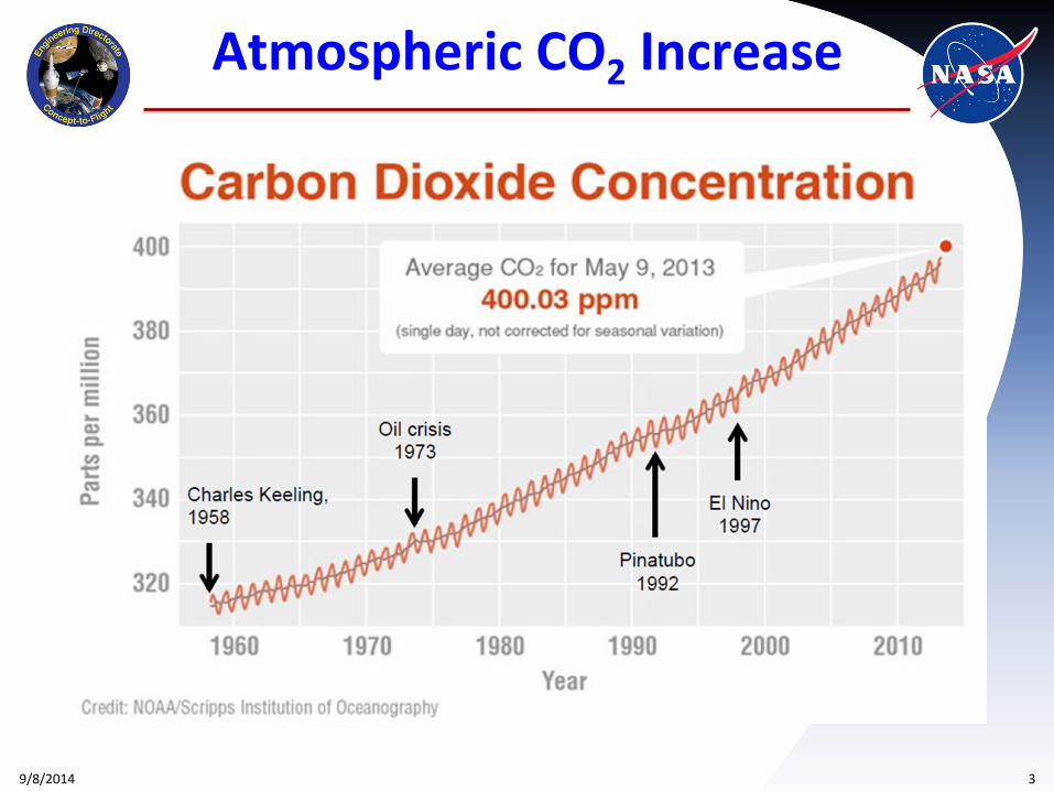
Atmospheric CO2 Increase
9/8/2014 4
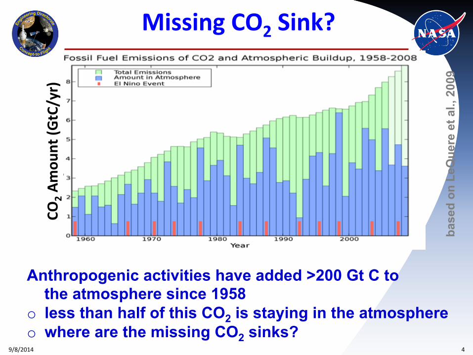
Missing CO2 Sink?
base
d on
LeQ
uere
et a
l., 2
009
Anthropogenic activities have added >200 Gt C to the atmosphere since 1958 o less than half of this CO2 is staying in the atmosphere o where are the missing CO2 sinks?
CO2 A
mou
nt (G
tC/yr)
9/8/2014 5
Co-Is/Partners: Jirong Yu, Mulugeta Petros, Syed Ismail, NASA LaRC
Key Milestones
Objective
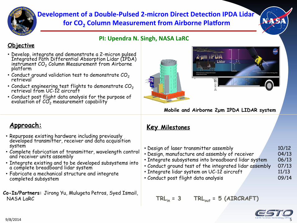
• Develop, integrate and demonstrate a 2-micron pulsed Integrated Path Differential Absorption Lidar (IPDA) instrument CO2 Column Measurement from Airborne platform
• Conduct ground validation test to demonstrate CO2 retrieval • Conduct engineering test flights to demonstrate CO2 retrieval from UC-12 aircraft • Conduct post flight data analysis for the purpose of
evaluation of CO2 measurement capability
Approach: • Repurpose existing hardware including previously
developed transmitter, receiver and data acquisition system
• Complete fabrication of transmitter, wavelength control and receiver units assembly
• Integrate existing and to be developed subsystems into a complete breadboard lidar system
• Fabricate a mechanical structure and integrate completed subsystem
• Design of laser transmitter assembly 10/12 • Design, manufacture and assembly of receiver 04/13 • Integrate subsystems into breadboard lidar system 06/13 • Conduct ground test of the integrated lidar assembly 07/13 • Integrate lidar system on UC-12 aircraft 11/13 • Conduct post flight data analysis 09/14
Development of a Double-‐Pulsed 2-‐micron Direct Detec&on IPDA Lidar for CO2 Column Measurement from Airborne PlaMorm
Mobile and Airborne 2µm IPDA LIDAR system
TRLin = 3 TRLout = 5 (AIRCRAFT)
PI: Upendra N. Singh, NASA LaRC
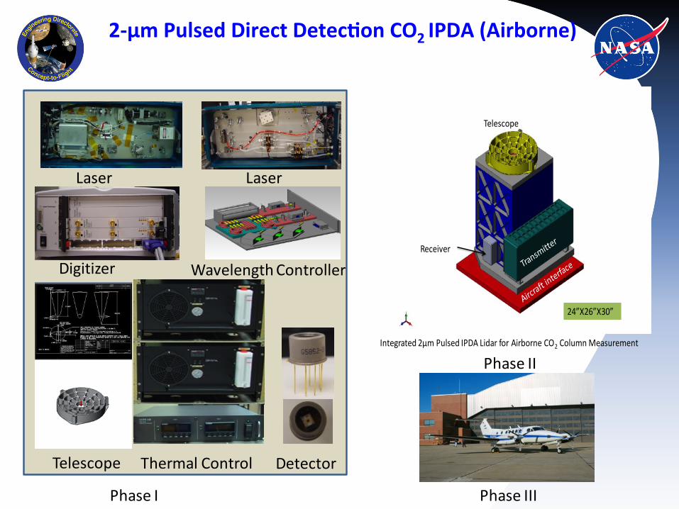
2-‐µm Pulsed Direct Detec&on CO2 IPDA (Airborne)
Telescope
Receiver
Integrated 2µm Pulsed IPDA Lidar for Airborne CO2 Column Measurement
24”X26”X30”
Phase I
Telescope Thermal Control
Digitizer Wavelength Controller
Laser Laser
Detector
Phase II
Phase III
9/8/2014 7
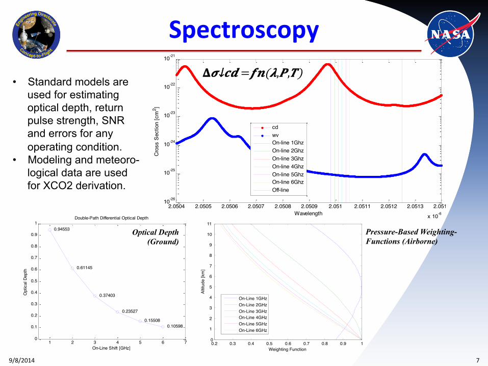
Spectroscopy
2.0504 2.0505 2.0506 2.0507 2.0508 2.0509 2.051 2.0511 2.0512 2.0513 2.0514
x 10-6
10-26
10-25
10-24
10-23
10-22
10-21
Wavelength
Cros
s Se
ctio
n [c
m2 ]
cdwvOn-line 1GhzOn-line 2GhzOn-line 3GhzOn-line 4GhzOn-line 5GhzOn-line 6GhzOff-line
𝚫𝝈↓𝒄𝒅 =𝒇𝒏(𝝀,𝑷,𝑻)
1 2 3 4 5 6 70
0.1
0.2
0.3
0.4
0.5
0.6
0.7
0.8
0.9
10.94553
0.61145
0.37403
0.23527
0.155080.10598
On-Line Shift [GHz]
Opt
ical
Dep
th
Double-Path Differential Optical Depth
Optical Depth (Ground)
0.2 0.3 0.4 0.5 0.6 0.7 0.8 0.9 10
1
2
3
4
5
6
7
8
9
10
11
Weighting Function
Altit
ude
[km
]
On-Line 1GHzOn-Line 2GHzOn-Line 3GHzOn-Line 4GHzOn-Line 5GHzOn-Line 6GHz
Pressure-Based Weighting- Functions (Airborne)
• Standard models are used for estimating optical depth, return pulse strength, SNR and errors for any operating condition.
• Modeling and meteoro-logical data are used for XCO2 derivation.
9/8/2014 8
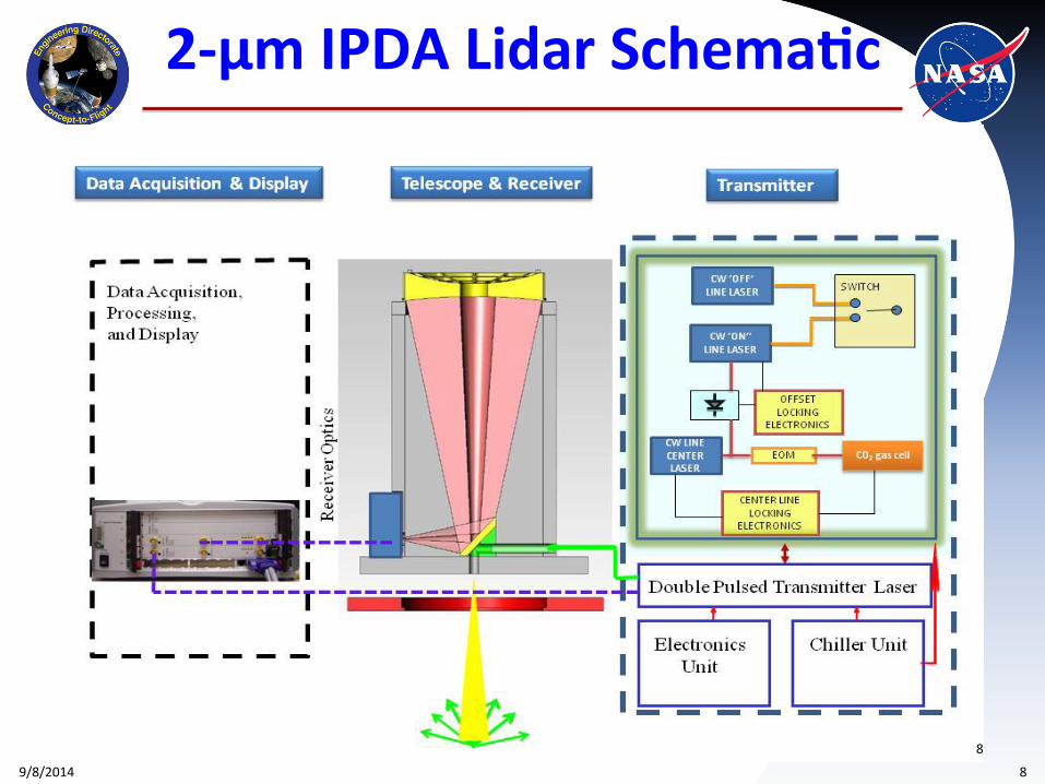
2-‐µm IPDA Lidar Schema&c
8
9/8/2014 9
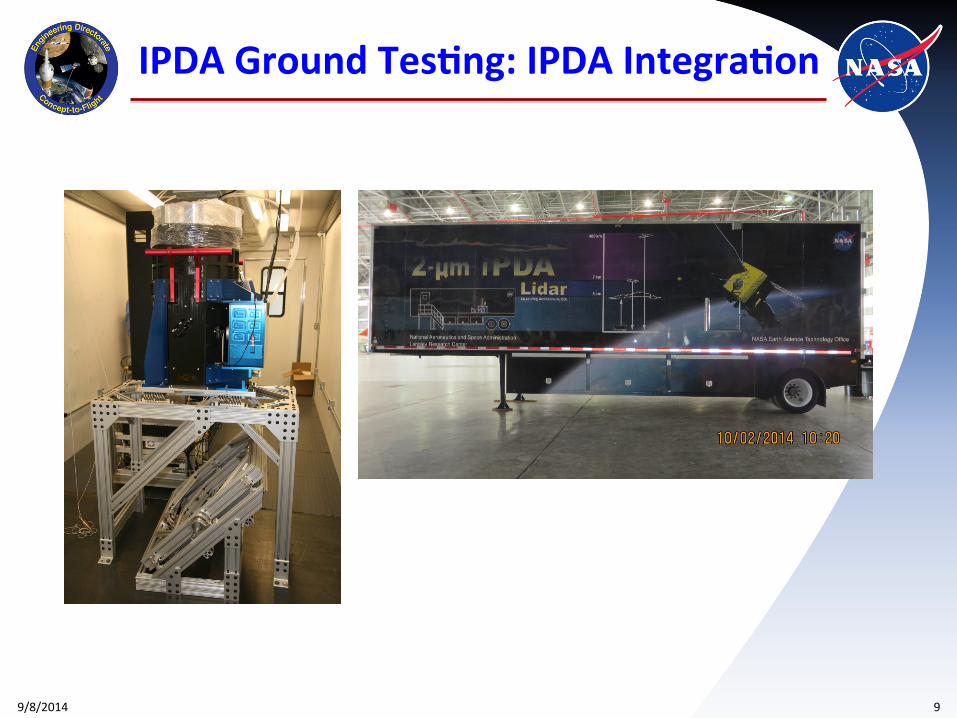
IPDA Ground Tes&ng: IPDA Integra&on
9/8/2014 10
IPDA Ground Tes&ng: Setup & Measurement
TARGET
CAPABLE
IPDA LIDAR
LICOR
INCINERATOR
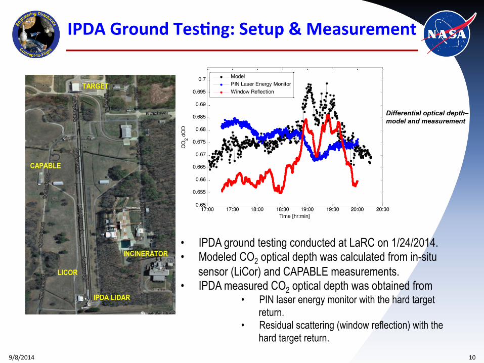
Differential optical depth– model and measurement
17:00 17:30 18:00 18:30 19:00 19:30 20:00 20:300.65
0.655
0.66
0.665
0.67
0.675
0.68
0.685
0.69
0.695
0.7
Time [hr:min]
CO2 d
OD
ModelPIN Laser Energy MonitorWindow Reflection
• IPDA ground testing conducted at LaRC on 1/24/2014. • Modeled CO2 optical depth was calculated from in-situ
sensor (LiCor) and CAPABLE measurements. • IPDA measured CO2 optical depth was obtained from
• PIN laser energy monitor with the hard target return.
• Residual scattering (window reflection) with the hard target return.
9/8/2014 11
IPDA Ground Tes&ng: Setup & Measurement
TARGET
CAPABLE
IPDA LIDAR
LICOR
INCINERATOR
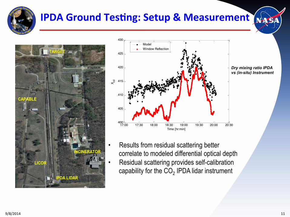
Dry mixing ratio IPDA vs (in-situ) Instrument
17:00 17:30 18:00 18:30 19:00 19:30 20:00 20:30400
405
410
415
420
425
430
Time [hr:min]
X cd
ModelWindow Reflection
• Results from residual scattering better correlate to modeled differential optical depth
• Residual scattering provides self-calibration capability for the CO2 IPDA lidar instrument
9/8/2014 12
IPDA Ground Tes&ng: Setup & Measurement
TARGET
CAPABLE
IPDA LIDAR
LICOR
INCINERATOR
17:00 17:30 18:00 18:30 19:00 19:30 20:00 20:30405
410
415
420
425
430
Time [hr:min]
X cd
ModelWindow Reflection
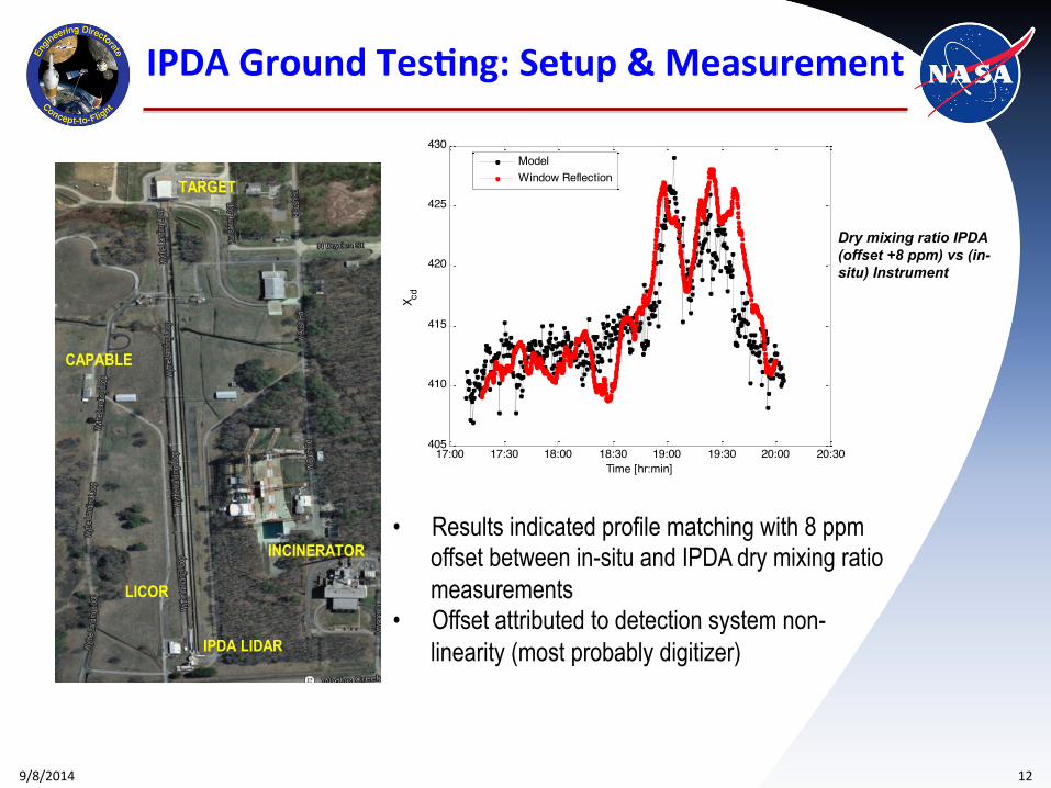
Dry mixing ratio IPDA (offset +8 ppm) vs (in-situ) Instrument
• Results indicated profile matching with 8 ppm offset between in-situ and IPDA dry mixing ratio measurements
• Offset attributed to detection system non-linearity (most probably digitizer)
9/8/2014 13
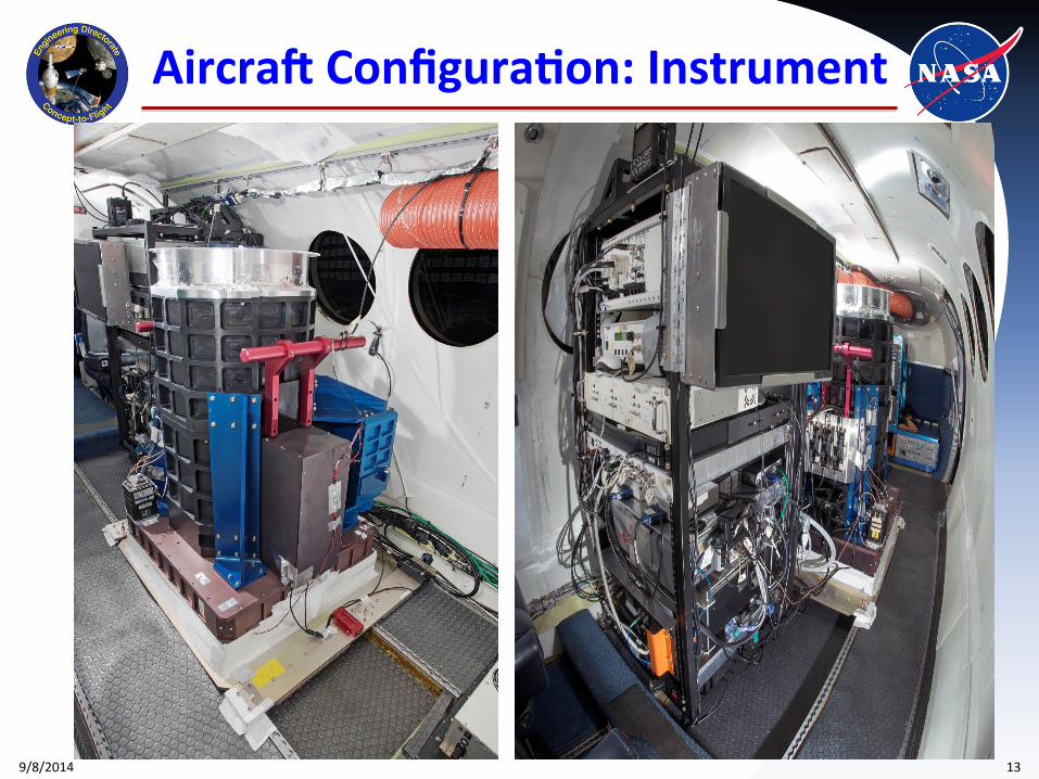
AircraV Configura&on: Instrument
LIDAR
LICOR
CAPABLE
INCINERATOR
9/8/2014 14
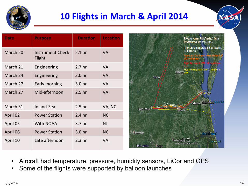
10 Flights in March & April 2014
Date Purpose Dura&on Loca&on
March 20 Instrument Check Flight
2.1 hr VA
March 21 Engineering 2.7 hr VA
March 24 Engineering 3.0 hr VA
March 27 Early morning 3.0 hr VA
March 27 Mid-‐aRernoon 2.5 hr VA
March 31 Inland-‐Sea 2.5 hr VA, NC
April 02 Power StaDon 2.4 hr NC
April 05 With NOAA 3.7 hr NJ
April 06 Power StaDon 3.0 hr NC
April 10 Late aRernoon 2.3 hr VA
• Aircraft had temperature, pressure, humidity sensors, LiCor and GPS • Some of the flights were supported by balloon launches
9/8/2014 15
IPDA Airborne Tes&ng: Sample Return Signals
0.2 0.4 0.6 0.8 1 1.2 1.4 1.6500
1000
1500
2000
2500
3000
3500
dOD
Altit
ude
[m]
US ModelIPDA ModelHigh Gain Channel + Window
20:00 20:15 20:30 20:45 21:00 21:150.2
0.4
0.6
0.8
1
1.2
High gain channel + High gain Window, 100-Avg
Time [hr:min]
dOD
MeasurementModel
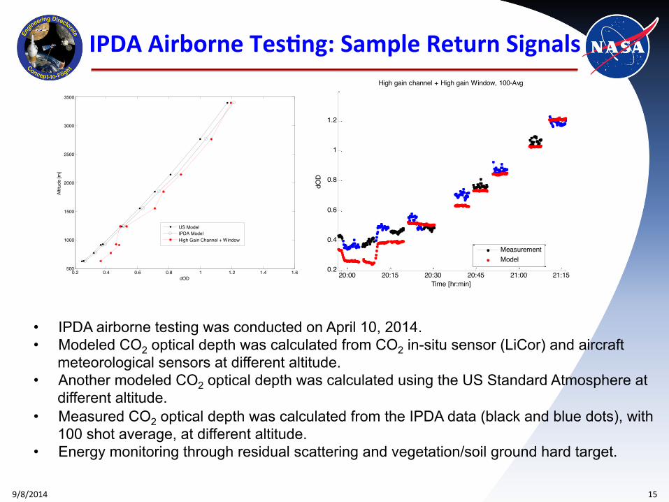
• IPDA airborne testing was conducted on April 10, 2014. • Modeled CO2 optical depth was calculated from CO2 in-situ sensor (LiCor) and aircraft
meteorological sensors at different altitude. • Another modeled CO2 optical depth was calculated using the US Standard Atmosphere at
different altitude. • Measured CO2 optical depth was calculated from the IPDA data (black and blue dots), with
100 shot average, at different altitude. • Energy monitoring through residual scattering and vegetation/soil ground hard target.
9/8/2014 16
IPDA Airborne Tes&ng: Sample Return Signals
0 1000 2000 3000 4000 5000 6000 7000 8000 9000 10000-0.2
0
0.2
0.4
0.6
Sign
al [V
]
Digitizer Samples
1530 m, 104 V/A
0 1000 2000 3000 4000 5000 6000 7000 8000 9000 100000
0.5
1
1.5
2
Sign
al [V
]
3988 m, 105 V/A
0 1000 2000 3000 4000 5000 6000 7000 8000 9000 100000
0.5
1
1.5
2
Sign
al [V
]
6125 m, 105 V/A
14:11 14:12 14:13 14:14 14:15 14:16 14:17 14:181480
1490
1500
1510
1520
1530
1540
1550
Time [min:sec]
Rang
e [m
]
GPS AltitudeIPDA Range MeasurementGPS Line-of-Sight
0.2 0.4 0.6 0.8 1 1.2 1.4 1.6 1.80
1000
2000
3000
4000
5000
6000
7000
dOD
Altit
ude
[m]
NOAA 4GHzNOAA 3GHzIPDA LidarUSA 3 & 4GHz
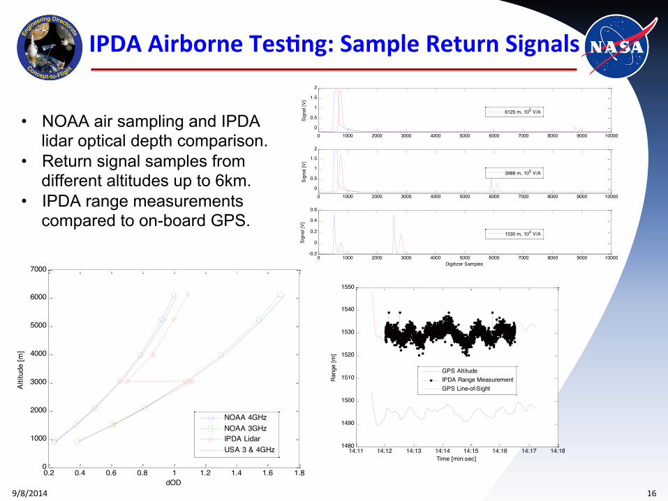
• NOAA air sampling and IPDA lidar optical depth comparison.
• Return signal samples from different altitudes up to 6km.
• IPDA range measurements compared to on-board GPS.
Objective
Key Milestones Approach
4/14 IIP-13-0048
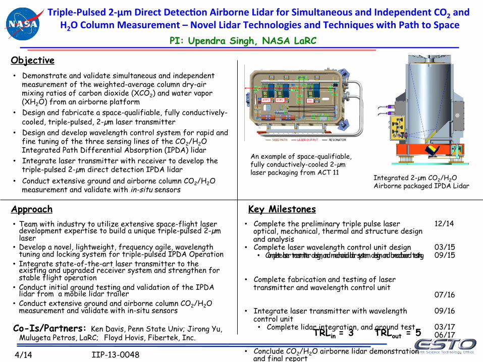
Triple-‐Pulsed 2-‐µm Direct Detec&on Airborne Lidar for Simultaneous and Independent CO2 and H2O Column Measurement – Novel Lidar Technologies and Techniques with Path to Space
PI: Upendra Singh, NASA LaRC
Co-Is/Partners: Ken Davis, Penn State Univ; Jirong Yu, Mulugeta Petros, LaRC; Floyd Hovis, Fibertek, Inc.
• Demonstrate and validate simultaneous and independent measurement of the weighted-average column dry-air mixing ratios of carbon dioxide (XCO2) and water vapor (XH2O) from an airborne platform
• Design and fabricate a space-qualifiable, fully conductively-cooled, triple-pulsed, 2-µm laser transmitter
• Design and develop wavelength control system for rapid and fine tuning of the three sensing lines of the CO2/H2O Integrated Path Differential Absorption (IPDA) lidar
• Integrate laser transmitter with receiver to develop the triple-pulsed 2-µm direct detection IPDA lidar
• Conduct extensive ground and airborne column CO2/H2O measurement and validate with in-situ sensors
• Team with industry to utilize extensive space-flight laser development expertise to build a unique triple-pulsed 2-µm laser
• Develop a novel, lightweight, frequency agile, wavelength tuning and locking system for triple-pulsed IPDA Operation
• Integrate state-of-the-art laser transmitter to the existing and upgraded receiver system and strengthen for stable flight operation
• Conduct initial ground testing and validation of the IPDA lidar from a mobile lidar trailer
• Conduct extensive ground and airborne column CO2/H2O measurement and validate with in-situ sensors
TRLin = 3 TRLout = 5
An example of space-qualifiable, fully conductively-cooled 2-µm laser packaging from ACT 11
Integrated 2-µm CO2/H2O Airborne packaged IPDA Lidar
• Complete the preliminary triple pulse laser optical, mechanical, thermal and structure design and analysis
• Complete laser wavelength control unit design • Complete laser transmitter design, and mechanical lidar system design and breadboard testing
• Complete fabrication and testing of laser transmitter and wavelength control unit
• Integrate laser transmitter with wavelength control unit • Complete lidar integration, and ground test
• Conclude CO2/H2O airborne lidar demonstration and final report
12/14 03/15 09/15 07/16 09/16 03/17 06/17
9/8/2014 18
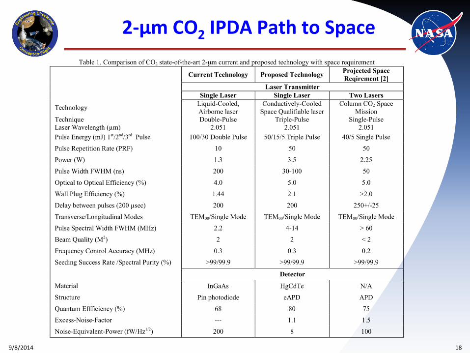
Table 1. Comparison of CO2 state-of-the-art 2-µm current and proposed technology with space requirement
Current Technology Proposed Technology Projected Space Reqirement [2]
Laser Transmitter Single Laser Single Laser Two Lasers
Technology Liquid-Cooled, Airborne laser
Conductively-Cooled Space Qualifiable laser
Column CO2 Space Mission
Technique Double-Pulse Triple-Pulse Single-Pulse Laser Wavelength (µm) 2.051 2.051 2.051 Pulse Energy (mJ) 1st/2nd/3rd Pulse 100/30 Double Pulse 50/15/5 Triple Pulse 40/5 Single Pulse
Pulse Repetition Rate (PRF) 10 50 50
Power (W) 1.3 3.5 2.25
Pulse Width FWHM (ns) 200 30-100 50
Optical to Optical Efficiency (%) 4.0 5.0 5.0
Wall Plug Efficiency (%) 1.44 2.1 >2.0
Delay between pulses (200 µsec) 200 200 250+/-25
Transverse/Longitudinal Modes TEM00/Single Mode TEM00/Single Mode TEM00/Single Mode
Pulse Spectral Width FWHM (MHz) 2.2 4-14 > 60
Beam Quality (M2) 2 2 < 2
Frequency Control Accuracy (MHz) 0.3 0.3 0.2
Seeding Success Rate /Spectral Purity (%) >99/99.9 >99/99.9 >99/99.9
Detector
Material InGaAs HgCdTe N/A Structure Pin photodiode eAPD APD Quantum Effficiency (%) 68 80 75 Excess-Noise-Factor --- 1.1 1.5 Noise-Equivalent-Power (fW/Hz1/2) 200 8 100
2-‐µm CO2 IPDA Path to Space
9/8/2014 19
Summary and Conclusions
Ø A 2-micron double-pulsed, high energy IPDA lidar system has been developed Ø 2-m CO2 IPDA lidar modeling estimates instrument performance and
calculates weighting function for deriving XCO2. Ø Preliminary analysis of ground based hard target measurement demonstrates
the 2-m CO2 IPDA lidar capability of measuring CO2 optical depth and deriving XCO2.
Ø The IPDA instrument was operated on NASA B-200 aircraft through different conditions
Ø IPDA capability was demonstrated from airborne platform Ø The measurement includes ranging capability with 1 m precision Ø Observed single-shot signal-to-noise ratio from hard target larger than 200 Ø Detailed data analysis is in progress Ø Future work towards developing a triple-pulsed IPDA lidar system is progressing
2-m IPDA Lidar Team members C. Boyer, B. Culliton, L. Cowen, J. Fay, W. Johnson, S. Johnston, M. Jones, E. Modlin, L. Murchison, I. Pang, P. Manhart, T. Notari , M. Petros , K. Reithmaier, T. Refaat, R. Remus, D. Reichle, S. Salvatore, U. Singh, J. Yu
9/8/2014 20
Publica&on List
1. J. Yu, M. Petros, K. Reithmaier, Y. Bai, B. Trieu, T. Refaat, M. Kavaya, U. Singh and S. Ismail, “A 2-micron pulsed integrated path differential absorption lidar development for atmospheric CO2 concentration measurements”, 26th International Laser Radar Conference (ILRC), Porto Heli, Greece, 2012.
2. U. Singh, J. Yu, M. Petros, T. Refaat and K. Reithmaier, “Development of a pulsed 2-micron integrated path differential absorption lidar for CO2 measurements”, Invited, Proc. of SPIE, Vol. 8872, 997209, 2013.
3. U. Singh, J. Yu, M. Petros, T. Refaat, K. Reithmaier, T. Kurosu, C. Miller and S. Dinardo, “Double-pulsed 2-micron integrated path differential absorption lidar development and column CO2 measurement from ground and airborne platform”, 10th International Workshop on Greenhouse Gas Measurements from Space, ESA-ESTEC, Noordwijk, The Netherlands, 2014.
4. U. Singh, J. Yu, M. Petros, T. Refaat, R. Remus, J. Fay and K. Reithmaier, “Column CO2 measurements from an airborne solid-state double-pulsed 2-micron integrated path differential absorption lidar”, International Conference on Space Optics, Tenerife, Canary Islands, Spain, 2014.
5. J. Yu, M. Petros, T. Refaat, K. Reithmaier, R. Remus, U. Singh, W. Johnson, C. Boyer, J. Fay, S. Johnson and L. Murchison, “2-micron pulsed direct detection IPDA lidar for atmospheric CO2 measurement”, First International Conference on Space-Based Lidar Remote Sensing Techniques and Emerging Technologies, Paris, France, 2014.
6. T. Refaat, M. Petros, R. Remus, J. Yu and U. Singh, “Laser energy monitor for double-pulsed 2-m IPDA lidar applications”, Proc. of SPIE, Vol. 9246, 924619, 2014.
7. U. Singh, J. Yu, M. Petros, T. Refaat, R. Remus, J. Fay and K. Reithmaier, “Airborne 2-micron double-pulsed integrated path differential absorption lidar for column CO2 measurement”, Proc. of SPIE, Vol. 9246, 924601, 2014.
8. T. Refaat, M. Petros, R. Remus, J. Yu and U. Singh, “Self-calibration laser energy monitor validation for double-pulsed 2-m CO2 IPDA lidar applications”, in preparation, Optical Engineering.
9/8/2014 21
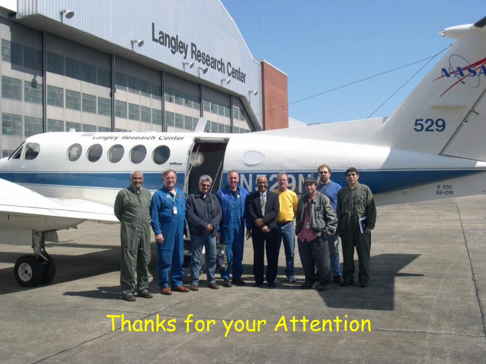
Thanks for your Attention