air heaters b 1 l/d 1 l - esparparts.com models/air heaters... · air heaters b 1 l/d 1 l technical...
TRANSCRIPT

()
Air heaters B 1 L/D 1 L Technical Description Installation Instructions Operating Instructions
Air heaters independent of engine B 1 L for petrol · D 1 L for diesel
Specifications
Heating medium Air
Hot air throughput'' 100 kg/h ± 10% (without counterpressure)
Heating capacity" 1800 W±10%
Fuel (see also page 1 0)
Fuel consumption''
Rated voltage
Operating range: Lower voltage limit" Upper voltage limit"
Electrical power consumption 1>
B 1 L: Gasoline, (commercial grade)
D 1 L: Diesel fuel, (commercial grade)
B 1 L: 0.241/h ± 5% D 1 L: 0.21 1/h ± 5 o/o
12Vor24V
10Vor20V 14 Vor 28 V
B.1L at start 200 W ± 10% operating 40 W ± 10%
D1L atstart 12V=260W±10%
24V=500W±10% operating 40 W ± 10%
B1L
Basic heater with standard equipment
Universal installation kit
D1L
Basic heater with standard equipment
Universal installation kit
Eberspacher
J. Ebersp8.cher Ebersp8.cherstr. 24 0-7300 Esslingen
Telefon (zentral) (0711) 31 09-0 Telefax (0711) 31 09-5 00
Cat no.
12 v 201590 05 00 00
201575 80 00 00
Cat no.
12V 251384050000 24 v 251385 05 00 00
12V 2516370500004'
24 v 25 1638 05 00 00 4'
201575 80 00 00
Control elements (to be ordered separately, see page 2). See Additional Equipment Catalog for other accessories.
Ventilation
Degree of radio interference suppression
Weight
" at rate voltage
Possible with suitable circuits
Remote; additional interference suppression measures possible
approx. 3 kg
21 an undervoltage safety device built into the control unit switches off the heaters when at approx. 10.5 V and 21 V respectively.
" an overvoltage safety device built into the control unit switches off the heaters when at approx. 15 V and 30 V respectively.
'' with glow plug current regulator
251637 90 89 53. 10.1991. Modification reserved. Printed in Germany. © Coovriaht J. Ebersoacher R 14/R1R
Contents Page
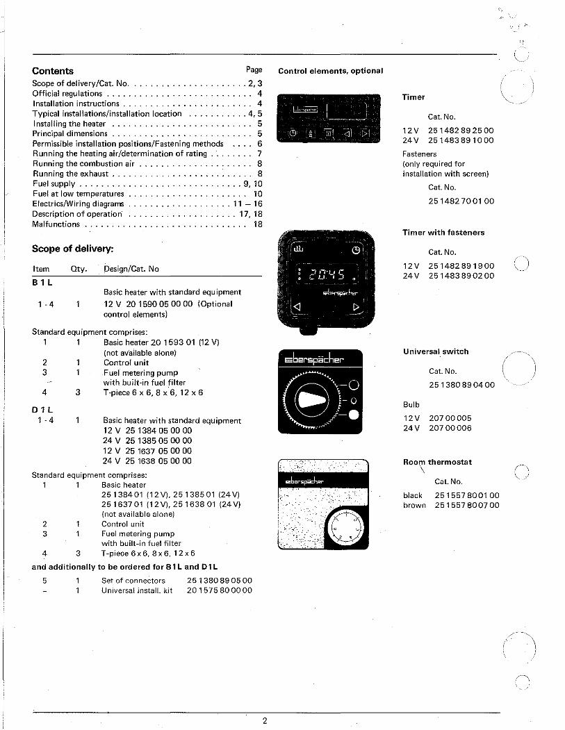
Scope of delivery/Cat. No ...................... 2, 3 Official regulations ........................... 4 Installation instructions . . . . . . . . . . . . . . . . . . . . . . . . 4 Typical installations/installation location ........... 4, 5 Installing the heater .......................... 5 Principal dimensions . . . . . . . . . . . . . . . . . . . . . . . . . . 5 Permissible installation positions/Fastening methods 6 Running the heating air/determination of rating . . . . . . . . 7 Running the combustion air . . . . . . . . . . . . . . . . . . . . . 8 Running the exhaust . . . . . . . . . . . . . . . . . . . . . . . . . . 8 Fuel supply .............................. 9, 10 Fuel at low temperatures . . . . . . . . . . . . . . . . . . . . . . 10 Electrics/Wiring diagrams ................... 11 - 16 Description of operation· .................... 17, 18 Malfunctions . . . . . . . . . . . . . . . . . . . . . . . . . . . . . . 18
Scope of delivery:
Item
B1l
1 . 4
Oty. Design/Cat. No
Basic heater with standard equipment
12 V 20 1590 05 00 00 (Optional control elements)
Standard equipment comprises: 1 1 Basic heater 20 1593 01 (12 V)
2 3
4
D1l 1 . 4
3
(not available alone) Control unit Fuel metering pump with built-in fuel filter T·piece 6 X 6, 8 X 6, 12 X 6
Basic heater with standard equipment 12 v 25 1384 05 00 00 24 v 25 1385 05 00 00 12 v 25 1637 05 00 00 24 v 25 1638 05 00 00
Standard equipment comprises: 1 1 Basic heater
2 3
4 3
25138401 (12V), 25 1385 01 (24 V) 251637 01 (12V), 251638 01 (24 V) {not available alone) Control unit Fuel metering pump with built-in fuel filter T -piece 6 x 6, 8 x 6, 1 2 x 6
and additionally to be ordered for 8 1l and D1l
5 Set of connectors Universal install. kit
25 1380 89 05 00 201575 800000
Control elements, optional
2
Timer
Cat. No.
12V 251482892500 24V 251483891000
Fasteners {only required for installation with screen)
Cat. No.
251482700100
Timer with fasteners
Cat. No.
12V 251482 891900 24V 251483890200
Universal switch
Cat. No.
251380890400
Bulb
12V 20700005 24 v 207 00 006
Room thermostat \
Cat. No.
black 251557 8001 00 brown 251557 8007 00
\ ~
()
-\. ' )
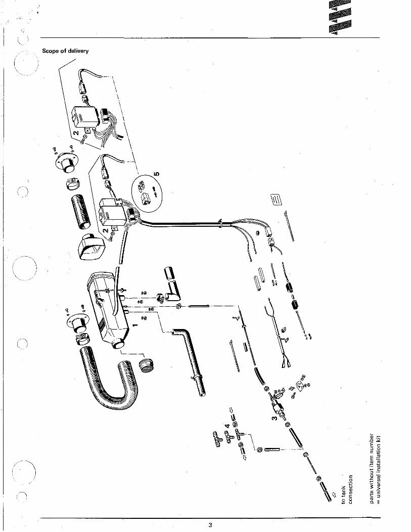
e of delivery Scop
3
Approval, official regulations, general
1. For vehicles registered in West Germany (subject to the road traffic regulations StVZO), the heaters are approved by the Federal Motor Vehicle Office and receive an official test symbol (81 L .J\N' 8133,01 L .J\N' S146) indicated on the name plnte).
The year of first operation is a requirement of German approval not representing a model number.
2. If the heater is installed in special-purpose vehicles (e. g. vehicles transporting dangerous cargoes), the regulations applicable to such vehicles must be observed.
3. The heater must not be operated in closed rooms, e. g. garages.
The heater must always be switched off when the petrol tank is to be filled.
4. The heaters must be installed by a workshop approved by the manufacturer and in compliance with the installation instructions.
5. The heaters may only be used for the purpose specified by the manufacturer and in compliance with the operating instructions supplied with every heater.
Operating the heater is not permitted where inflammable vapours or dust can build up (e. g. near fuel, coal or sawdust stores, grain silos etc.). Spray cans and gas cartridges in the vehicle must be kept out of the heating t:~ir .current.
Installation Instructions
The suggestions put forward in these installation instructions are only examples. Possibilities other than those illustrated (e. g. with regard to the choice of installation location, means of running air) are also permissible, provided they meet the requirements of the West German road traffic regulations (StVZO), and if necessary after consultation with the manufacturer.
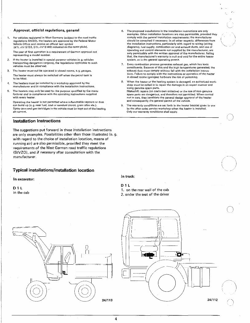
Typical installations/installation location
In excavator:
D1L in the cab
@ 24/113
4
6. The proposed installations in the installation instructions are only examples. Other installation locations are also permissible, provided they comply with the general installation requirements: the manufacturer should be consulted if necessary. In all other respects, differences from the installation instructions, particularly with regard to wiring (wiring diagrams), fuel supply, combustion air and exhaust ducts, and use of operating and control elements not supplied by the manufacturer, are only permissible with the written approval of the manufacturer. Failing that, the manufacturer's warranty is null and void for the entire heater system, as is the general operating permit.
7. Every combustion process generates exhaust gas, which has toxic constituents. Because of this and the high temperatures generated, the exhaust duct must comply without fail with the installation instructions. Failure to comply with the instructions or operation of the heater in closed rooms (garages) harbours the risk of poisoning.
8. When the heater or the heating system is damaged, an authorized workshop must be called in to repair the damage in an expert manner and using genuine spare parts. Makeshift repairs (on one's own initiative) or the use of non-genuine spare parts are dangerous, and therefore not permitted. When carried out in cars, they invalidate the general design approval of the heater and consequently the general permit of the vehicle.
9. The warranty conditions are set forth in the heater booklet given to you by the after-sales service workshop when the heater is installed. Only our warranty conditions shall apply.
In truck:
D1L 1. on the rear wall of the cab 2. under the seat of the driver
24/112

B1L/D1L · .. in vehicle interior
, - (Dp.h--"~~ b-@--l'«f~ Lm-:/@_ c __ _
1. Heater under rear seat, inside or outside
2. Heater in front of passenger seat
3. Heater on center console
24/111a
Installing the heater
The 8 3 L and D 3 L heaters are suitable and approved for installation in vehicle areas used by passengers.
--. In the case of installation in passenger areas, the exhaust, . \.combustion air and fuel lines in these areas must not have any
) detachable connections, and must be splash-water-tight at the / penetrations to the outside.
For this reason, the heater must be mounted by its base on an outside panel of the vehicel or on its floor, Using the seal seated on the base.
The factory plate must be clearly visible even when installed. If necessary a second factory plate (duplicate) may be affixed, with the same information as the original, to a place on the heater clearly visible after installation, or to a cover placed in front of the heater. A second plate is not necessary if the original is visible after removal of a cover without the aid of tools.
Principal dimensions Only push in vent line so far that there is no short circuit at the positive contact of the Free space for
fitting plug I plug
356
/-) Combustion air
Vent line only in interior fittings for West Germany
5
-~_,I
24/101 d

Permissible installation positions
21/279a
Fastening to the vehicle wall/floor Make penetrations in accordance with the templet pattern.
Templet pattern
The holes for the 8 mm-dia. vent lines and for the 10.5 mm-dia. metering pump/control unit cable are not included in the templet pattern, and must be drilled to suit the installation arrangement.
The mating surface for the heater base must be smooth. To drill the penetrations and if necessary to smooth the mating surface, a special tool is available from the manufacturer under Cat. No. 99 1201 46 53 29.
Special tool
21/144
6
In general the heater should be installed in standard position, as shown.
If this is not feasible, please consult the manufacturer.
During starting an thermostatic operation a heater installed in the standard position may deviate, due to the inclination of the vehicle during motion, from this standard position up to± 15° in both axes.
Continuous heating operation after starting is even possible at a deviation from standard position of up to± 30°.
With deviations exceeding± JQO a reliable continuous heating operatioli is no longer possible. However, this does not lead to damage of the heater if the deviation occurs only for a short interval.
Important: The plug connection piece must always face upwards.
*~ ( : :.a-:.--)~---·---
/ Heater base
' This must be smooth Seal 21/280
*This must be kept free. Check for free running of fan wheel.
If the mating surface sheet is too thin (criterion: less than 1.5 mm), a reinforcing plate- Cat. No. 20 1577 89 00 03-can be instaUed additionally on the outside.
Seal
\ Heater
0 Reinforcing plate
Vehicle wall
Spring washer
I~ I~
\Hex. nut
Reinforcing plate
21/2.
I

( J
Running the heating air 2 1 Standard components for running heating air. 1111
5 6 3 4 31 -1--,--(1 ~ 11---1--1111~
I u~ 7 1 2 3 4
11-11-1-----j 21/282
Item Designation Component Cat. No rating
1 Protective grid 0.4 20 1465 8g 05 00 2 Connection piece, 50 mm dia. 0.4 20 1575 80 08 01 3 Hose clip, 50· 70 mm dia. 10 2064 05 00 70 4 Flex. pipe, 50 mm dia. lin. m. 1.0perm 10 2114 2g 00 00
5 Protective grid, 50 mm dia. 0.1 20 1575 8g 20 00 6 Hood 0 20 1465 8g 00 01
7 Air outlet, rotatable, 50 mm dia. 1.25 201575 80 08 00 goo bend of flex pipe, 50 mm dia. 0.4
Do not connect too many components. The sum of the component ratings may not exceed the heater rating. See Additional Equipment Catalog for further parts.
Example of determination of rating:
Heater rating 10
CAUTION: Do not use a fastening clamp here. The heater casing must not be distorted.
2 3
¢111• 1111111111111111111111111111111111111111111111111
' .._ __ ,_, ___ ..J
21/283
Item Designation Component Cat. No rating
1 Protective grid 2 Connection piece, 50 mm dia. 3 0.3 flexible pipe, 50 mm dia. 4 1.0 m flexible pipe, 50 mm dia. 5 Reduction hood, 50 mm dia., straight 6 2 x goo bends of flexible pipe
(0.4 rating for each) 7 Exhauster, rotatable
Sum of component ratings
The sum of the component ratings does not exceed the heater rating of 10, installation is therefor permissible.
When checking an installation, the average outlet temperature should not at the outlet point significantly exeed 11 0°C with an intake temperature of 20°C. This will ensure that the safety thermal cutout switch will not respond under normal operating conditions.
7
0.4 0.4 0.3 1.0 0.0 0.8
1.25
4.15
20 1465 8g 05 00 20 1575 80 08 01 20 2114 2g 00 00 2021142goooo 20 1465 8g 00 01
201575800800
Heating air intake openings shall be arranged in such a manner that exhaust from the vehicle's engine and from the heater cannot be expected to be sucked in under normal operating conditions, and the heating air cannot be contaminated.
When operating as a recirculating heater, locate the inlet for the heating air in such a way that the outflowing hot air cannot be sucked directly in again.

Running the combustion air/Running the exhaust Permissible diameters, lengths, bends of combustion air and exhaust lines.
, r '-<6'
) I
Combustion air .n Exhaust
Combustion air line internal dia. 15 mm min. 100- max. 220
B 1 L
220
Combustion air line internal dia. 15 mm min. 300
D1L 400
400 - max. 1000 same length as exhaust line
Measurements in millimeters
Permissible blend
Exhaust line: max. 1800 Combustion air line: max. 180°
The scope of delivery includes an exhaust pipe, 270 mm long, with 90° bend, and a combustion air tube, 500 mm long, with 90° bend.
These can be shortened as required. Longer pipes are available as given in the Additional Equipment Catalog.
Additional noise suppression is possible by installing an exhaust silencer (see chapter "Exhaust Parts" in the Additional Equipment Catalog). The permissible length of the ex· haust line is reduced here by the length of the exhaust silencer.
The combustion air must be sucked in from the outside, not from the passenger compartment or trunk.
Do not install the intake opening facing the slipstream, but run it in such a manner that dirt and snow cannot enter and that any water which does enter can flow out.
8
Exhaust pipe internal dia. 24 mm min. 100- max. 270
270 - max. 500 ... Exhaust pipe internal dia. 24 mm or flex. pipe internal dia. 30 mm
180- 270
270-400
400 - max. 1000 same length as combustion air line
21/284
Exhaust lines
B 1 L max. 500 mm long D 1 L max. 1000 mm long must not be exceeded.
Exhaust lines must not project beyond the sides of the vehicle. They must be laid either with a slight slope or with 5 mm dia. holes at the lowest points for draining off condensate.
Arrange the exhaust outlet and the combustion air opening such that the exhaust cannot be sucked back in directly.
The exhaust outlet must be on the outside. Exhaust lines must be laid in such a way that neither the penetration of exhaust into the vehicle interior nor the intake of exhaust through the vehicle or heater blowers need be expected1
), and that the operation of essential vehicle parts is not affected (ensure adequate clearance). Place the outlet opening of the exhaust line in such a way that it cannot be clogged by dirt and snow and that any water which does enter can run off. Do not install facing the slipstream. I) This requirement can be considered met if the outlet
opening of the exhaust line is located at the usual places in motor vehicles, e.g. in engine compartment, in wheel case, on the vehicle underside, or on the rear of the cab.

/)
±c --------------------------------------------------------------------~~------...
Fuel supply \ The instructions given here should not be disregarded as deviations may cause malfunctions.
1. Fuel intake from fuel line to engine (usually in passenger cars): Precondition: the fuel line from the fuel tank to the engine must be tight so that the flow of fuel is not interrupted when the engine iS not running.
~-----f-~~~ Fuel line connection to heater .- """-· • 2 r--". to engine -· el· 1 r--•'T '-->" I f I 1 .
1
~ ii0 e ec. ue pump • 0
: y ~ in .. J·ect~·on pump I . -A I
L__ ___ :_j_ J 4 {~l>l 6. 7
~~~/· ~-
1
c V 1 Tank 2 Fuel branch
a 3 Fuel tube, internal dia. 5 mm
Dimension a
Dimension b Dimension c Dimension d
max. 2000 mm for gasoline max. 5000 mm for diesel oil
50mm max. 300 mm max. max.
4 m for gasoline 6 m for diesel oil
At all joints, fuel pipe (7) and connection pieces must touch.
2. Fuel intake separately from fuel tank or separate tank (usually in trucks, construction machinery, agricultural machinery)
A 8 c
intake from above lateral intake at tank lateral intake or beneath it; metering pump below lowest fuel level
-i I I • 1 • I I • ' I I
With connection types A and B, the intake line -A includes tank connection (8) -including all connection points must have an internal dia. of 2 mm; for this reason, fuel pipe {10) and connections must touch each other at every joint.
9
4 Fuel pre-filter (vertical, up to 30° downward if fuel I i ne is tapped) Cat. No. 25 1226 89 00 37, only necessary if fuel is contaminated
5 Fuel metering pump (15° to vertical, inclined upward) 6 Fuel tube, internal dia. 3.5 mm 7 Fuel pipe, plastic, internal dia. 1.5 mm 8 Tank connection, internal dia. 2 mm 9 Tube or plastic pipe (max. internal dia. 5 mm)
10 Fuel pipe, plastic, internal dia. 2 mm
Dimension a
Dimension f
Dimension d
24/140d
max. 2000 mm with gasoline max. 5000 mm with diesel oil max. 500 mm with gasoline max. 1000 mm with diesel oil max. max.
4 m with gasoline 6 m with diesel oil

3. Permissible suction and pressure heads for installation per 1. and 2.; permissible positioning of metering pump
max. fuel level Fuel line connection to heater
~ 9 ~"" 15° to vertical
I \ ·"~· --~..".""'150 --11--'il ... -,.,
e
Metering pump
Supply pressure from tank to metering pump: e = max. 3000 mm suction head: tank at zero pressure
f = max. 500 mm with gasoline max. 1000 mm with diesel oil
Check whether tank ventilation works properly
intake from tank when underpressure occurs during operation (valve 0.03 bar in tank cap) f = max. 150 mm with gasoline
max. 400 mm with diesel oil
Pressure head metering pump to heater: g = max. 2000 mm f ____ j_
min. fuel level 24/141b Fuel line metering pump to heater should not have a slope if
at all possible.
4. lmpQrtant
Protect fuel lines, filter and metering pump from overheating; do not install near silencers and exhaust pipes. Temperatures above 30° C lead to gas bubbles and problems with gasoline.
When installing the fuel line, fuel filter and fuel metering pump near the rear axle, be sure to takte the spring deflection of the rear axle into consideration.
Cut fuel tubes and pipes to length only with a sharp knife. Cuts may not be indented and must be burr-free.
For connection of the fuel branches, always use rubber tubing, never plastic pipe.
Fuel grades/Fuel at low temperatures
The heater can take without problem the same fuel you use in your tank. In the USA diesel fuel no.1 and no. 2. Admixture of used oil is not permitted.
The refineries automatically adapt their fuels to normal winter temperatures (Winter Diesel).
Therefore difficulties can only arise at extremely low temperature (as in the engine- see the vehicle's instruction manual).
If the heater is operated from a separate tank, the following rules must be observed: at temperatures above 0° C any type of diesel fuel can be used. If no special cold-weather diesel fuel is available at low temperatures, mix kerosine or gasOline according to the adjacent table.
10
Fuel pipes connected by means of a fuel tube.
Fuel pipe sections must abut.
Do not let fuel tube sag.
Temperature Winter Additive diesel oil
From oocto -15°C"" 100%
From -15°C to -25°C 50% 50% kerosine or gasoline
100% kerosine*
* or special winter diesel oil?. "*or in accordance with fuel manufacturer's specifications
The fuel line and the fuel pump must be filled with new fuel by operation for 15 minutes.
Fuel for special cases
In special cases, the heaters can also be operated on extra light fuel oil (above 0°C) or kerosine. If in doubt consult the manufacturer.

Electrics:
Arrange electric cables, switches and control units in the vehicle in such a way that their correct functioning cannot be impaired under normal operating conditions.
Fit the control unit so that it is protected from splash water (from both its own vehicle and preceding ones). Outside installation is thus not permissible. The unit is best arranged in the vehicle interior, with the plugs pointing downward.
Control unit
Permissible installation angles
21/286a
The pilot light (built into the switch or timer) should be within the field of vision of the driver, or at least be visible to him without great effort.
Install the room thermostat where it is sheltered from draughts and sunlight. Do not fit it to non-insulated outer walls.
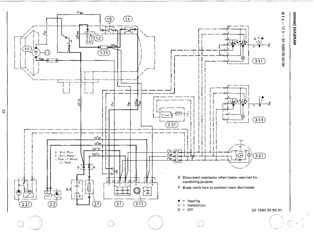
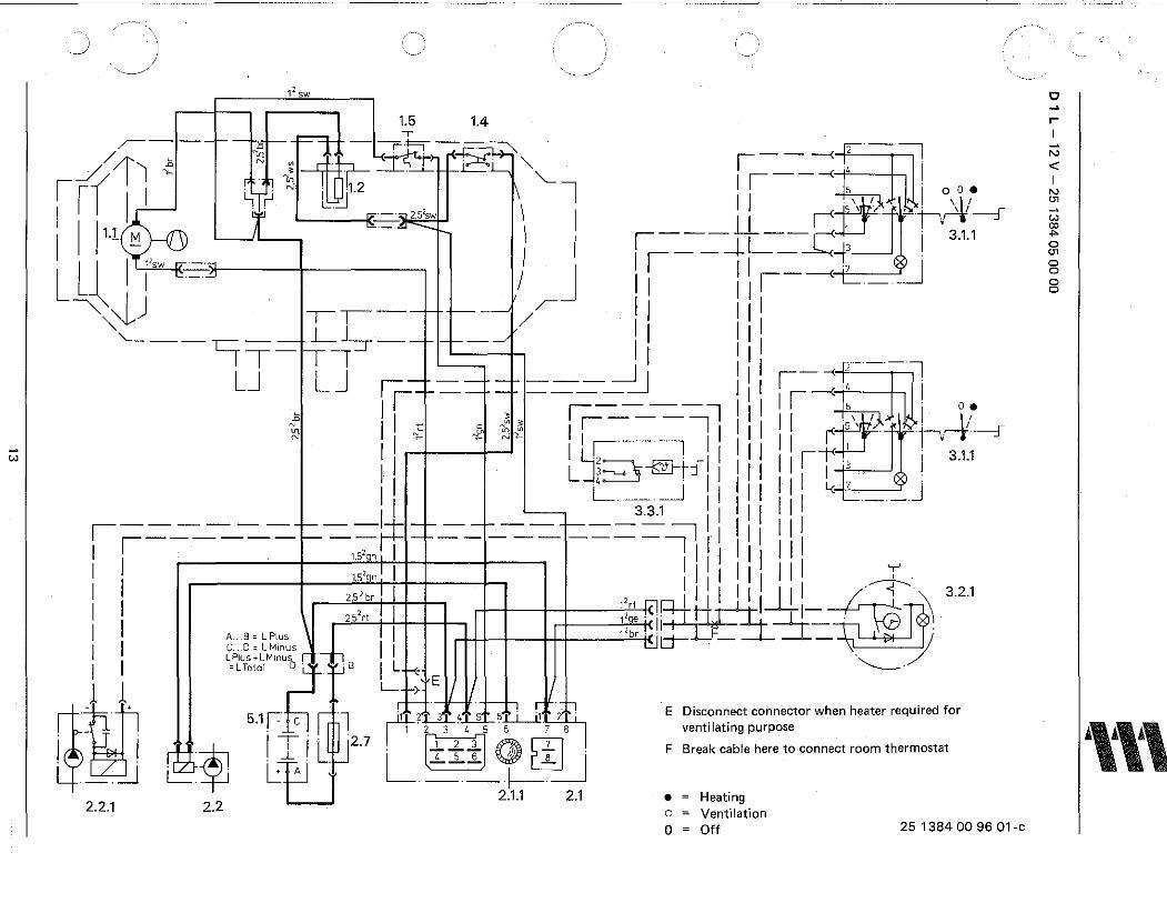
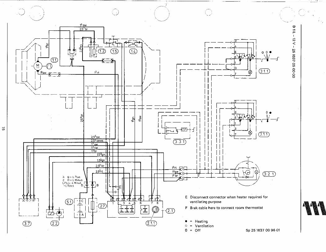
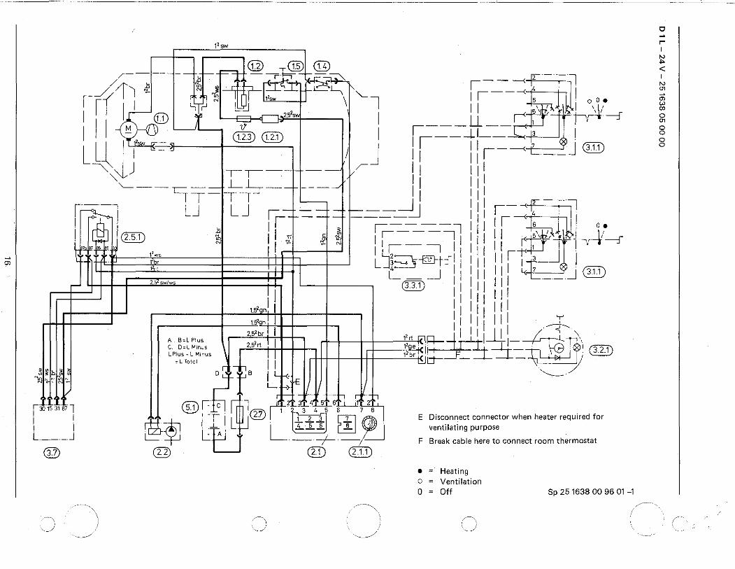
Parts list to wiring diagram B 1l page 12 and wiring diagrams D 1l page 13-16.
1.1. Blower motor (.} 1.2. Glow plug
1.2.1. Glow plug drop resistor 1.2.3. Temperature fuse 1.4. Temperature switch 1.5. Safety thermal cutout switch 2.1. Control unit 2.1.1. Motor fuse 2.2. 2.5.1. 2.7. 3.1.1. 3.2.1. 3.3.1. 2.2.1. 3.7. 5.1.
Fuel metering pump Relay for glow plug Main fuse 16 Amp.
Universal switch ~ Timer Thermostat Optional addition parts Circulation pump Glow plug current regulator Battery
11
The following cable cross~sections must be observed between battery and heater, in order that the maximum permissible voltage losses in the cables (0.5 at 12 V rated voltage and 1 V at 24 V) are not exceeded.
L + + L- < 5 m -? cross-section 4 mm2
L + + L- 5 to 8 m """*cross-section 6 mm2
21/286b
If the positive cable is to be connected to the fuse box (e.g. terminal 30), the vehicle's cable too from the battery to the fuse box must be included in the calculation of the total line length, and if necessary redimensioned in accordance with the above.
Smear plug and earth connections with contact protection grease outside the vehicle interior.
rt ~ red br ~ brown ws= white sw= black gn = green ge ~ yellow vi ~ violet
12sw
®@ ~-----lc- --..,... -~-k---"' r·; I ·---,~ til. .
//1---, i; • . n i+ S., . " '- - ---< ' :l __/ I I .,_ • ~ E.......:L....-, I ' I ~~~~ I ~ 1l-t@ \ "--l ~~----< s i o 0
•
I (1.1) ~ r ~- zs'sw I I 1 If- t! ___}L CD:D - ' 1 ,---=- ·_j_l_-_-ci ~~ 1
1'sw~-~ I I . · Ll~ I, " ... ~ I J I i lr-----< 7
___ j GID ""'~j --,r--·- r-- r- II I
"- / I '--- __ c::::::; _ _ L :S- _ _ r--· __/ I I I IT-TI I i --LJ LJ r-- -- _____ __j I I ,--< 2 ;-]
I,------ ____ =._j ---<' I i; 11 • r;::------=--;l 1 II s a.
c:l § ~
:0 ,... I z
G)
"' 0 < j;: I G)
"' :0
0 )> s
"' "' 0 0
"' 0 0 0 0
~
"' II ILF·-~ 11 1 II t'' r 1 I L )~ s-m-t-:f I I 1 I I I 1 J I II L_ ____ j I I I 111 ~ 7 _j (ED I GJD I I 111 --
~-=-....=-------=---=... ~ - =f=ti =t + -=---=._--= =-=-~ I / I I II I J tS'an I ~~~~~ 1/1 I I ts'on 1 1 IIIII Ill Y I I zs'brTI 1111 I jll -~ I I A .... B~LPles , II ,,r, R-J.Wi~ ~- ~ ~n C . D = L Minus 2,5 rt 12 . . . . J.;. I l . \
I I l Pies •l Mines ~ -h T I ,,;-t<II-+:I ~=IJ=- " Cili) 1 I ~ l Total I, I 1 i ~IT- -- - - :'J/ I I D L_tB I i._-<:·. I . "---- / 1 1 ,.- '-- -> E
~~. • . ~ [~ rt---1 ft :t± r:f·f, E Disconnect connector when heater required for
j= C l 1 ?L.IL~.:.L2L~J:....L....J.1. 2 ventilating purpose - . -~ 1 3t.56 78
I fM .. ~ 5.11 T I 1 1 " 8' 2 3~ ~I; p 1
2 II 1
I F Break. cable here to connect room thermostat . - -L . L L t. s 6 e_ I I
_ ~ c L:.B -t ==- -=---.J L_j • = Heating G}D @ @ @ 2·1. 1 o = Ventilation
0 = Off 20 1590 00 96 01
w
_) . \
J 12sw
1.5 1.4
~----1--rjj =n-~-;-!::::_,.1+'- ~--~ r .11 _// 11 ,.a N ~ . . . 1-CL ""- I ~---< ' I
, ,v I I - '-i. ~ ~· '[:Qf.2 I '·1 l I I r-<rtt r~~~ ,II ~-~ I 1 I'
I 111.1 )j A ~. = ---r- ) : ~-----Llf--_ c:: I 3.1.1
I ll I 1'>w IT-· j J 1 I I 1 _ ~ ·-~ L ~ I ~. ~ I 11
~ ~j -r-r--·- r---- /~ /I I ""---- -- LS-·- j--·...../ Ill II
LJ LJ ·- -·-·-r---_j_j 11 I ~' 1 LJT-TI I -l Jll r,-r--·-·- ----=----=-- II II "- , i· 0~
~I I I cf ,~ ~~ ii --. ll l1 l i r~ I·~~ 1 I 1 W, I I 1 I I I I 1-t<t-J I 3.1.1
I I LJi--. §-oo-t-::11 1 II 111 l , J I I L.- _j I I II Ill ·-·-· I I 3.3.1 I I I I I
------·-r---f=tr-r---r-----t----:::::l I II II i ~-----.-r--,s~l~-t------ ----l1ll
11 ill ~
I I 152ac
1 I I I I I I I I -~ 3 2 1
I I "",I ••• "j+BJ . : 1
_1!_,_ # ~w .. I I 252
ct ! I ~: II· ~-=- r · I I A Bo LP.f_e> J ! I IT - ~~ I C 0 o L Mmu> I I II ·-......__ / I LPiu>•LMmu>,r, .!.!s I l · I 1 o L Total D Lf-t t"*: E
• 123456 78
I - I ~ ·~ I \I ~ 2.7 ·L 8, ~ ~~ () ~
I I ~- L:.B -+ ·-·-1-· . -. ::....J L._j 2.1.1 2.1 2.2.1 2.2
E Disconnect connector when heater required for ventilating purpose
F Break cable here to connect room thermostat
• = Heating o = Ventilation 0 = Off 25 1384 00 96 01-c
0 ~
r I
"' < I
"' "' ~ w ~ 0
"' 0 0 0 0
.,,,

...
1~ sw
- -·--+- f-- - ' /~ ~ ~- -r!=l-t;"£---,~ - -; i 1.5 1.4
_/ 11 J: N J, r . ~ 1-i!:._SL, r-- ~------< : ;-"] Jr:; I j . •·f1 N I R;-~2sw \ "-l I I -<~1 11 '-ir l.l:~ 6 ·oo•
I ~~~-~ ·~ · ,_,:sw I II ~rrjl ;-Ji~ I 1.1 !:1 1)' ~- ,----'' __ I ...u I'· J
l~ I l'sw . ::_"-. 1.2.3 1.2.1 I
1
~- _ j_ j __ =-c. 3 ! 3.1.1
L I "· -~ 1 j I I I 7 J ~ lj 11 111----< ·-·-· '-~ -r-r---- -·- /~ IJ 111 '----- c -- L:!:-::r--·- ----~ Ill ill
IT-TI I 1 11
i. I LJ LJ ,----- ___ _jl ljl ,-l .ill
I ! I I+----+- ---- _=--.J I I I I ----<; ' .
1 " 11 ,---_ --- 1 1 II I . 2.5.1 ~ I " c }. I I-- - ;-1 I I
6
, I i 0
~ ®., N I I "- "" ~ I I ·-· I I I I I I r<+¥ ' -;--,,---~----:f Tit . 12ws I 1 ~ I I 1 I 1 1 I I --H:U 1. '
I ,; L Jz-.... j---tjB-t:f I I I I I I I I I 3 I 3.1.1
L _j IIIII III~' _j. __ zs2swlws -- ·-:3.3.1 I I ill --
,- -- -!-r-l-f-- ---- f---·------, 11 111 ill I ,------1----r,-1-f------ ----~I I I I j 1.52an I I j j j I j I I I I j j ts2nn I 111111111J :
I 25 2 b' I I I I 1 I 1 I 1 11 I -~
j A .. B~LPI_os __ 2 I 12ct-lilrl I~ I l---1...!... ~ -~ c ... D::LMmus 2~-rt 12qe- -~M J-
1 j LPius•LM;nus l-i, 1 2 ~JI=!-H-f-i--l.-j-!-_jJ__~Th. 3.2.1 1 I ~LTotal . II I 1bc~~-~ _ ___l__~} I I ~'. ·t B I Lf-<- '--/ 11 Lf->E
~;' i= c @l · b1. J ,f st J i :;f·;:f]_ E Disconnect connector when heater required for
J · --,- · 1 2 3 4 5 6 ~-~ ventilating purpose
_. ::!J i M~ 5-tj_A I ~-2
_7
L 8' ~. ~~ F ~ I ' 1 F Break cable here to connect room thermostat
2.2.1 2.2 :.r:..J 2.1 2.1.1
"\
.. __/
• = Heating o = Ventilation 0 = Off 25 1385 DO 96 01-1
c ~
r-1
'!;: < I
"' "' ~ w 00
"' 0
"' 0 0
8
_.c'·--
~
"'
-~ J 12sw 2,52 br
c ~ N
"' N;
12 rt
r--::__- -< 2 - ::::;-]
II --<~-I I s I _,, oo•
~--· _u __ r---<~_5, '· , _I . \1;
I r- - - _J_ I_ 1---<..Lr l'r'f -----:r I I -~ 3 I
I I ~~~----< 7 ·-~ ®J)
-~
I II I I I 1 I 1 I
r;:: +-+-- I 11
1
11+-+--+::t==--=-_jl 111 _ I ~-~ I ~~-~a~
J1 JJ jr----=---:lllllf--<: I , 1 I I 1 ~- 1
11 I I I II ~. , I ot ;;:_' 1_ L'J,~>--r'll 111 11 ,W rr-f__, ~::: L - _j I I I I I I I I 3 I II r 1'bc QJJ) Ill 1111 1111 l<: 7 J. (3.1.1)
1.5
2
an I I ·--t'kn 1 1 I I I 1 I I I
2s'b, 1 1 I I I 1 I II
, , ~, e~ ''" II ,~ I I I I 1 II I 'r
AJ{t·· LL .Ll 13o 1s 31 87
I I I I I .
'---·-·J
@
[p,,~:,'~~~~s \1 . I II oil '~19_-- :; I l :Jlll \·/~' -LTotot. ~r-l B . 1'b;:-t': I __1_!_.- =@H
t I LHE --;1\o---- _ ___1_- ..- \
4--1->' - . ([[I) ®~~-~1 '>,,_,UJL '----7 r/1, I ~ 1 ~ cmr'f .c', •, , , 'o ' ''"'""'""""-' t..:::::: -~ ~tJ-A . L ~" e f : ~1!--~ _I_ ventilating purpose when heater required for
@ . -· . )ji!t! l@ F Brak cable here to c - . - ~ onnect room th ermostat
@ •= . Heat1ng 0 = Ventilation 0 = Off Sp 25 1637 00 96 01
c ~
r-1
N
< I
N
"' "' w " 0
"' 0 0 0 0
.,,,
~
Ol
1'sw
,r-----l-1r @ .@ ® / " - 'rn-t_r:::----.~ ~11 ~ .l(}. ~J_r D-P=-"' or:::, 1". ,---{ r I If
Ill I I '-i rJ N llo~ l,•.. \ '---l I r-----< ~ I I I I ·~(jJ) t 2,5'" I I . 1':1 J'-- 1i -- I I
l~ l'''sw ". "~ @ <ITD I ~~---LI--_::C.I 1$. 1 L I I J II 11,---{ 7 J CTID ~ lj 11 1
--
"'-'-...1 -rr---- --- vr- 11 111 '--------c:::--- L:!:-:r--- ----~
111 111
--- IT Tl I Ill
~l LJ LJ ,- - - t----__j 1 Ill ,---<~ J [ I 1-1-- - - ____ -=._j Ill I 4 .
I " I ---- 11--<s I CITD ~ I I ,1' ~ ~ ii--=- -~l II : I I ~. L. ~ ~
.t ""' I I 1 ~ I I 1 I I I I I r +J I • ll ,,,; LJ~...,_, ']-@J-t:f I i I I I I I IT 3 I
r 2 •wlw l_ _ __j 1111111111 '<7
_j@
I 11 CITD I II II --
1 1 II l1 Ill
~J~~~l '
r~_tfl . 30153187 I I I . I I L ___ J
®
1.52anl 11111
111 II t<'anl 11111111 ';'
2,5' b• I I 1 1 I 1 · ----:r----A e,L PI"' I 1'rt 1 I I I I ~ '\ C .. D=L M1nus 2,5
2rt 12q~ 9. ~~ 1 ~~___L_!_I_ TJ. \
LPio••L"""' l 1 12 ~~~11 ____!_l__~ WJ J~l rT'J1\
,LTotal II 1b> d--- _ _!__~1 ; ~ I i_~J J "---- /
L. I->
@ l_fcl ~~l ~ u'!A5~~ 1
---r- . ® r, ~ 6 , "
~~ lt-JLT L~rn~ @ ® CITD
E Disconnect connector when heater required for ventilating purpose
F Break cable here to connect room thermostat
• = Heating o = Ventilation 0 = Off Sp 25 1638 00 96 01 -1
0 -r I
~ < N
"' 0'> w co 0
"' 0 0 0 0

J J 1 2 3 lllO c
~~ (I)
:.:. en .., ::!.
Q_~
-· :J" g. =::o ~ " " " :I
" " " 0 a iJ\ 3
Ilf> ~-c 0 :J" -0 "
'C
" :;; (I)
" 0! :;· g. ~· :I
25 " ~ 22 ---
clli -"'-U i!D:~.5.1
Eberspiic.her
~
14 e~ _(I
""ber-spacher lal!lllll
" 0 24
20
1 Hot-air blower 14 Cumbustion air tube F = cold air 2 Electric motor 15 Exhaust pipe W= hotair 3 Combustion air blower 16 Fuel metering pump V = combustion air 4 Glow plug 17 Fuel strainer A = exhaust 5 Safety thermal cutout switch 19 Main fuse B = fuel 6 Combustion chamber 20 Control unit 7 Temperature switch 21 Motor current fuse
8 Heat exchanger 22 Universal switch
'tt\ 9 Casing 23 Timer 10 Connection flange 24 Room thermostat 11 Fuel connection 25 Timer 12 Screen for combustion air
21/286 a 13 Plug area ventilation
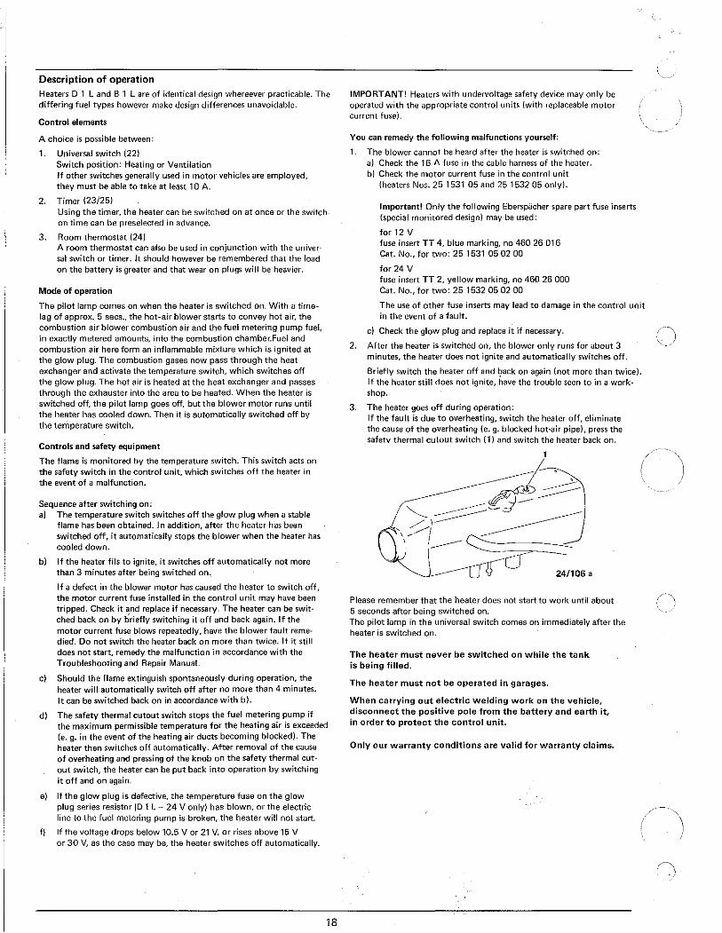
Description of operation Heaters D 1 L and 8 1 L are of identical design whereever practicable. The differing fuel types however make design differences unavoidable.
Control elements
A choice is possible between:
1. Universal switch (22) Switch position: Heating or Ventilation If other switches generally used in motor vehicles are employed, they must be able to take at least 10 A.
2. Timer (23/25) Using the timer, the heater can be switched on at once or the switchon time can be preselected in advance.
3. Room thermostat (24) A room thermostat can also be used in conjunction with the universal switch or timer. Jt should however be remembered that the load on the battery is greater and that wear on plugs will be heavier.
Mode of operation
The pilot lamp comes on when the heater is switched on. With a timelag of approx. 5 sees., the hot-air blower starts to convey hot air, the combustion air blower combustion air and the fuel metering pump fuel, in exactly metered amounts, into the combustion chamber.Fuel and combustion air here form an inflammable mixture which is ignited at the glow plug. The combustion gases now pass through the heat exchanger and activate the temperature switch, which switches off the glow plug. The hot air is heated at the heat exchanger and passes through the exhauster into the area to be heated. When the heater is switched off, the pilot lamp goes off, but the blower motor runs until the heater has cooled down. Then it is automatically switched off by the temperature switch.
Controls and safety equipment
The flame is monitored by the temperature switch. This switch acts on the safety switch in the control unit, which switches off the heater in the event of a malfunction.
Sequence after switching on: a) The temperature switch switches off the glow plug when a stable
flame has been obtained. In addition, after the heater has been switched off, it automatically stops the blower when the heater has cooled down.
b) If the heater fils to ignite, it switches off automatically not more than 3 minutes after being switched on.
If a defect in the blower motor has caused the heater to switch off, the motor current fuse installed in the control unit may have been tripped. Check it and replace if necessary. The heater can be swit· ched back on by briefly switching it off and back again. If the motor current fuse blows repeatedly, have the blower fault remedied. Do not switch the heater back on more than twice. If it still does not start, remedy the malfunction in accordance with the Troubleshooting and Repair Manual.
c) Should the flame extinguish spontaneously during operation, the heater will automatically switch off after no more than 4 minutes. It can be switched back on in accordance with b).
d) The safety thermal cutout switch stops the fuel metering pump if the maximum permissible temperature for the heating air is exceeded (e. g. in the event of the heating air ducts becoming blocked). The heater then switches off automatically. After removal of the cause of overheating and pressing of the knob on the safety thermal cutout switch, the heater can be put back into operation by switching it off and on again.
e) If the glow plug is defective, the temperature fuse on the glow plug series resistor (D 1 L- 24 V only) has blown, or the electric line to the fuel metering pump is broken, the heater will not start.
f) If the voltage drops below 10.5 V or 21 V, or rises above 15 V or 30 V, as the case may be, the heater switches off automatically.
18
IMPORTANT! Heaters with undervoltage safety device may only be operated with the appropriate control units (with replaceable motor current fuse).
You can remedy the following malfunctions yourself:
1. The blower cannot be heard after the heater is switched on: a) Check the 16 A fuse in the cable harness of the heater. b) Check the motor current fuse in the control unit
(heaters Nos. 25 1531 05 and 25 1532 05 only).
Important! Only the following Eberspacher spare part fuse inserts (special monitored design) may be used:
for 12 V fuse insert TT 4, blue marking, no 460 26 016 Cat. No., for two: 25 1531 05 02 00
for 24 V fuse insert TT 2, yellow marking, no 460 26 000 Cat. No., for two: 25 1532 05 02 00
The use of other fuse inserts may lead to damage in the control unit in the event of a fault.
c) Check the glow plug and replace it if necessary.
2. After the heater is switched on, the blower only runs for about 3 minutes, the heater does not ignite and automatically switches off.
Briefly switch the heater off and back on again (not more than twice). If the heater still does not ignite, have the trouble seen to in a work· shop.
3. The heater goes off during operation: If the fault is due to overheating, switch the heater off, eliminate the cause of the overheating (e. g. blocked hot-air pipe), press the safetv thermal cutout switch (1) and switch the heater back on.
1
~~~ ~~~;J-/1 - -------------
\-/"/ ______ ~ I
24/106 a
Please remember that the heater does not start to work until about 5 seconds after being switched on. The pilot lamp in the universal switch comes on immediately after the heater is switched on.
The heater must never be switched on while the tank is being filled.
The heater must not be operated in garages.
When carrying out electric welding work on the vehicle, disconnect the positive pole from the battery and earth it, in order to protect the control unit_
Only our warranty conditions are valid for warranty claims.