air force advanced instrument school
DESCRIPTION
I n t e g r i t y - S e r v i c e - E x c e l l e n c e. AIR FORCE ADVANCED INSTRUMENT SCHOOL. Procedures & Techniques. PROCEDURES & TECHNIQUES Back to Basics. PROCEDURES & TECHNIQUES Objectives. Review Instrument Cross-check HUDs Reintroduce 60 - 1 Rule - PowerPoint PPT PresentationTRANSCRIPT
AIR FORCE ADVANCED
INSTRUMENT SCHOOL
Procedures & Techniques
I n t e g r i t y - S e r v i c e - E x c e l l e n c e
PROCEDURES & TECHNIQUES Back to Basics
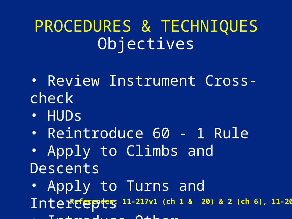
PROCEDURES & TECHNIQUESObjectives
• Review Instrument Cross-check• HUDs• Reintroduce 60 - 1 Rule• Apply to Climbs and Descents• Apply to Turns and Intercepts• Introduce Other Applications
References: 11-217v1 (ch 1 & 20) & 2 (ch 6), 11-202v3
BASICS
“An aircraft is flown in instrument flight by controlling the attitude and power as necessary to produce the desired performance.”
AFM 11-217v1, para 1.1
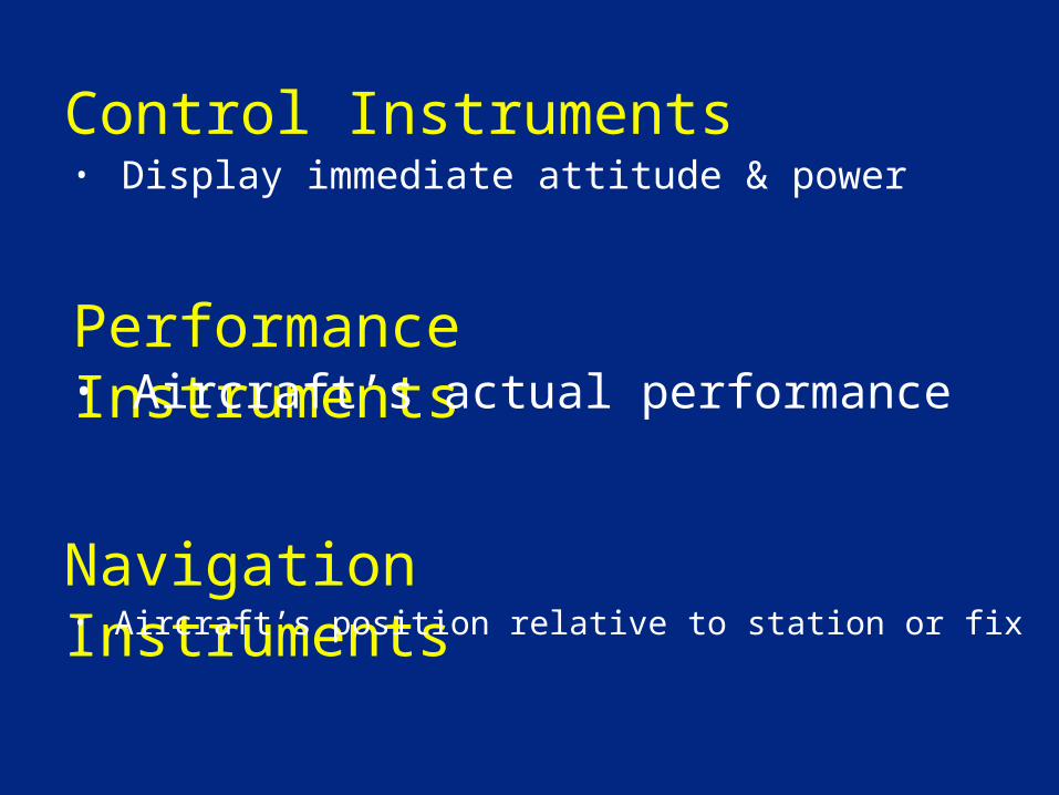
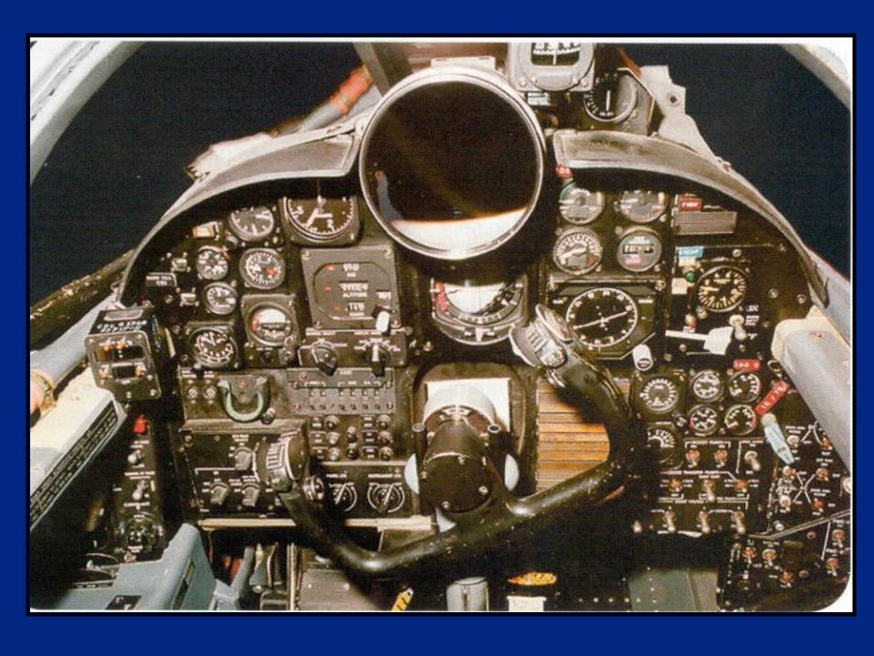
Control Instruments• Display immediate attitude & power
Performance Instruments
Navigation Instruments
• Aircraft’s actual performance
• Aircraft’s position relative to station or fix
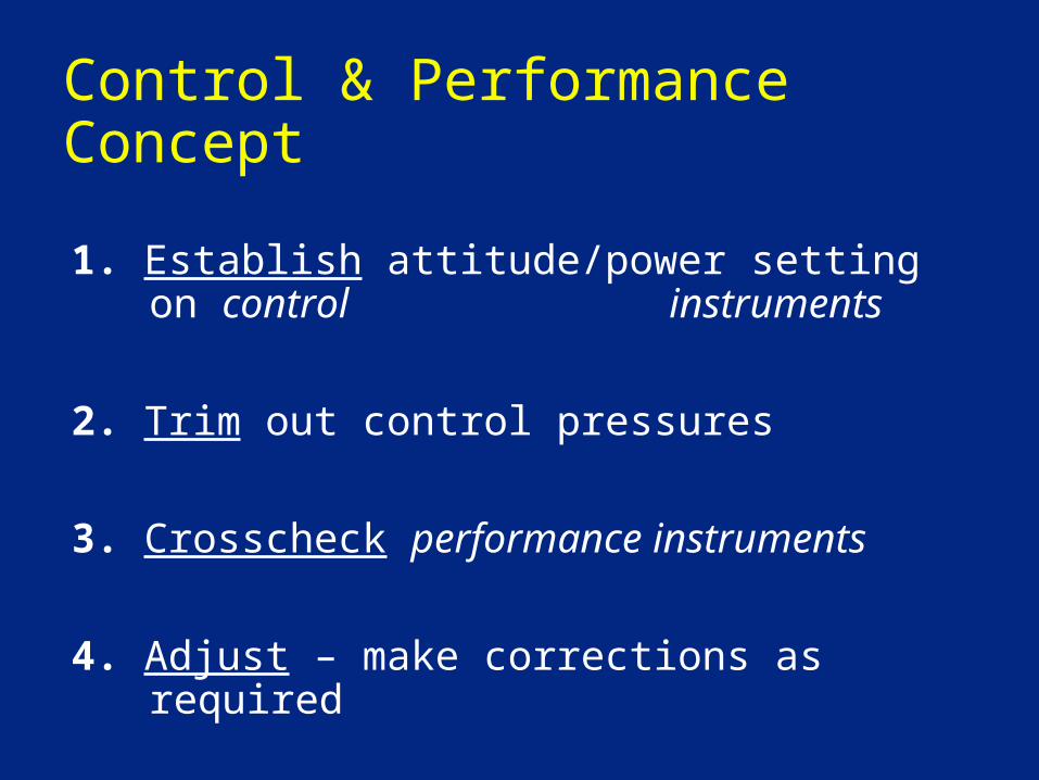
Control & Performance Concept
1. Establish attitude/power setting on control instruments
2. Trim out control pressures
3. Crosscheck performance instruments
4. Adjust – make corrections as required
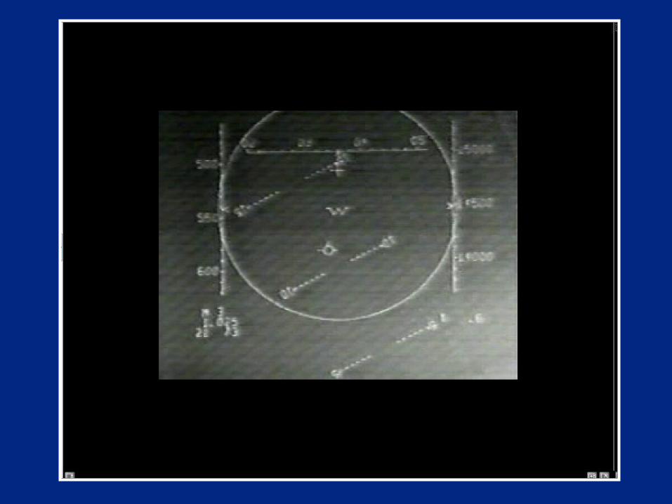
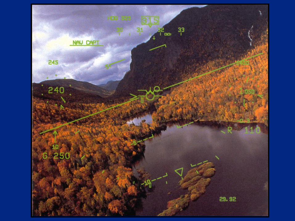
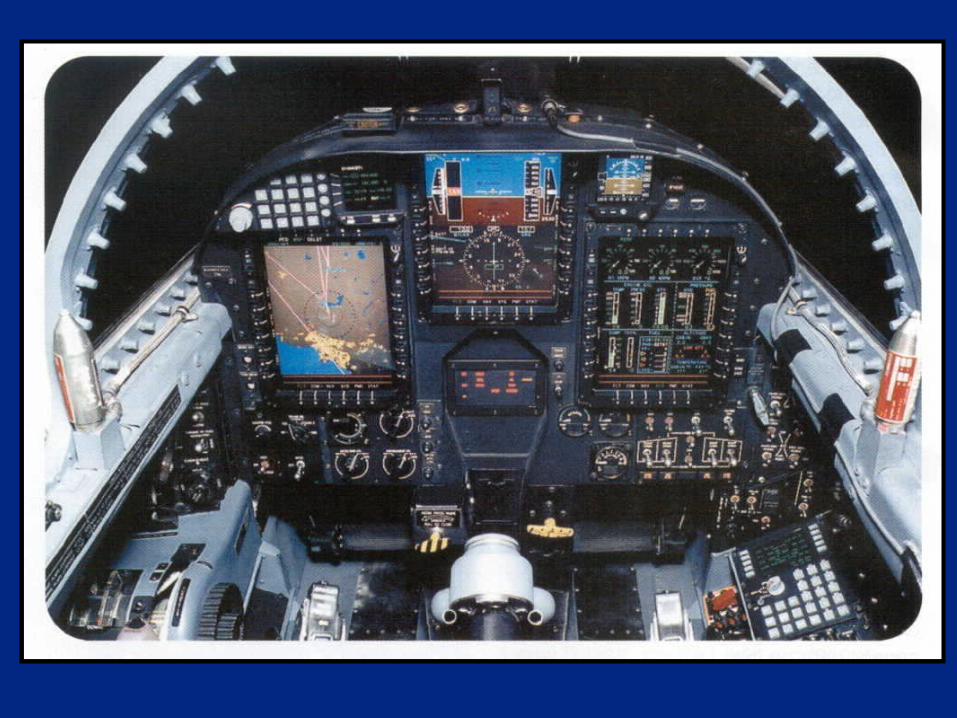
HEAD-UP DISPLAYS
2.6.1. Flight Instrumentation. Primary flight instrumentation must provide full-time display of attitude, altitude, and airspeed information and the capability to recognize, confirm, and recover from unusual attitudes. Information must be positioned and arranged in a manner enabling an effective pilot crosscheck.
AFI 11-202v3
HEAD-UP DISPLAYS
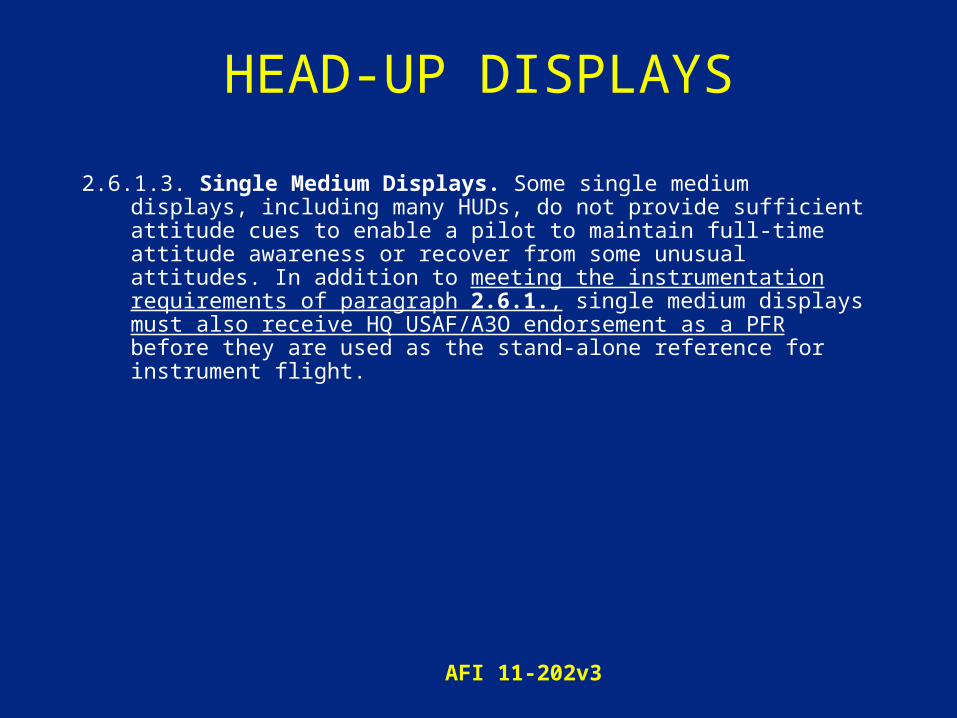
2.6.1.3. Single Medium Displays. Some single medium displays, including many HUDs, do not provide sufficient attitude cues to enable a pilot to maintain full-time attitude awareness or recover from some unusual attitudes. In addition to meeting the instrumentation requirements of paragraph 2.6.1., single medium displays must also receive HQ USAF/A3O endorsement as a PFR before they are used as the stand-alone reference for instrument flight.
AFI 11-202v3
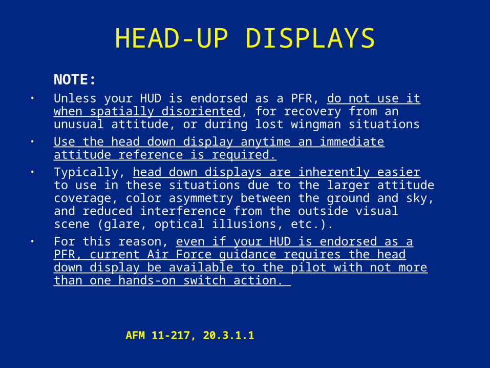
HEAD-UP DISPLAYS NOTE: • Unless your HUD is endorsed as a PFR, do not use it when
spatially disoriented, for recovery from an unusual attitude, or during lost wingman situations
• Use the head down display anytime an immediate attitude reference is required.
• Typically, head down displays are inherently easier to use in these situations due to the larger attitude coverage, color asymmetry between the ground and sky, and reduced interference from the outside visual scene (glare, optical illusions, etc.).
• For this reason, even if your HUD is endorsed as a PFR, current Air Force guidance requires the head down display be available to the pilot with not more than one hands-on switch action.
AFM 11-217, 20.3.1.1
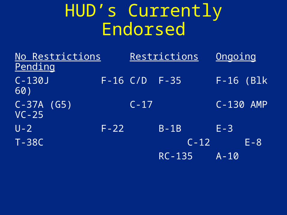
HUD’s Currently Endorsed
No Restrictions Restrictions Ongoing Pending
C-130J F-16 C/D F-35 F-16 (Blk 60)
C-37A (G5) C-17 C-130 AMP VC-25
U-2 F-22 B-1B E-3
T-38C C-12 E-8
RC-135 A-10
Source: AFFSA, AF Research Laboratory
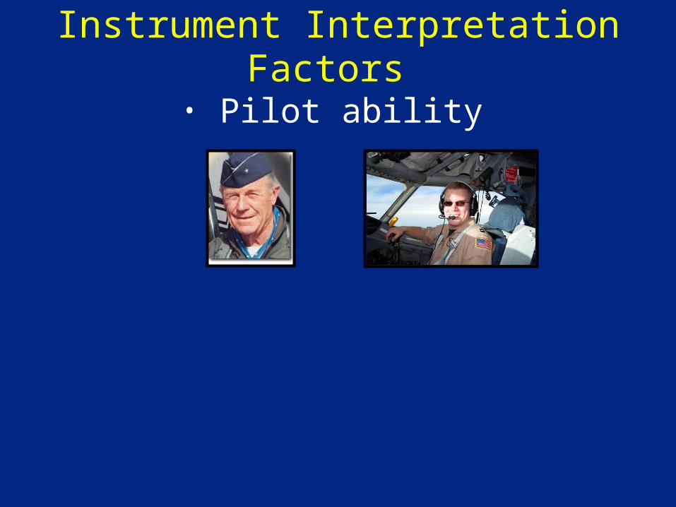
Instrument Interpretation Factors
• Pilot ability
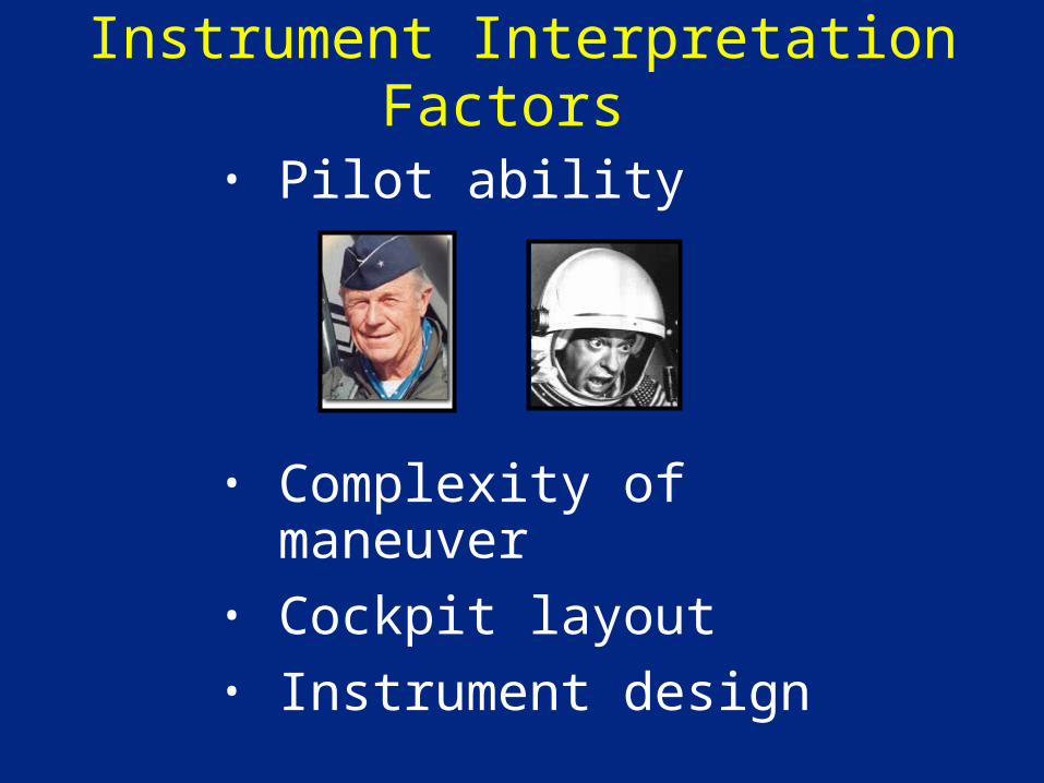
Instrument Interpretation Factors
• Pilot ability
• Complexity of maneuver• Cockpit layout• Instrument design
COMMON PROBLEMS
• Fixation• Omission• Fast Scan• Inadequate Trimming
Improving Fundamental Skillsand Correcting Fundamental Errors
• Slow down cross-check• Know what to change and by how much
• Known pitch/power settings• Know interplay between control &
performance corrections• Small corrections
• Set…Trim…Crosscheck…Adjust
60-1 RULE
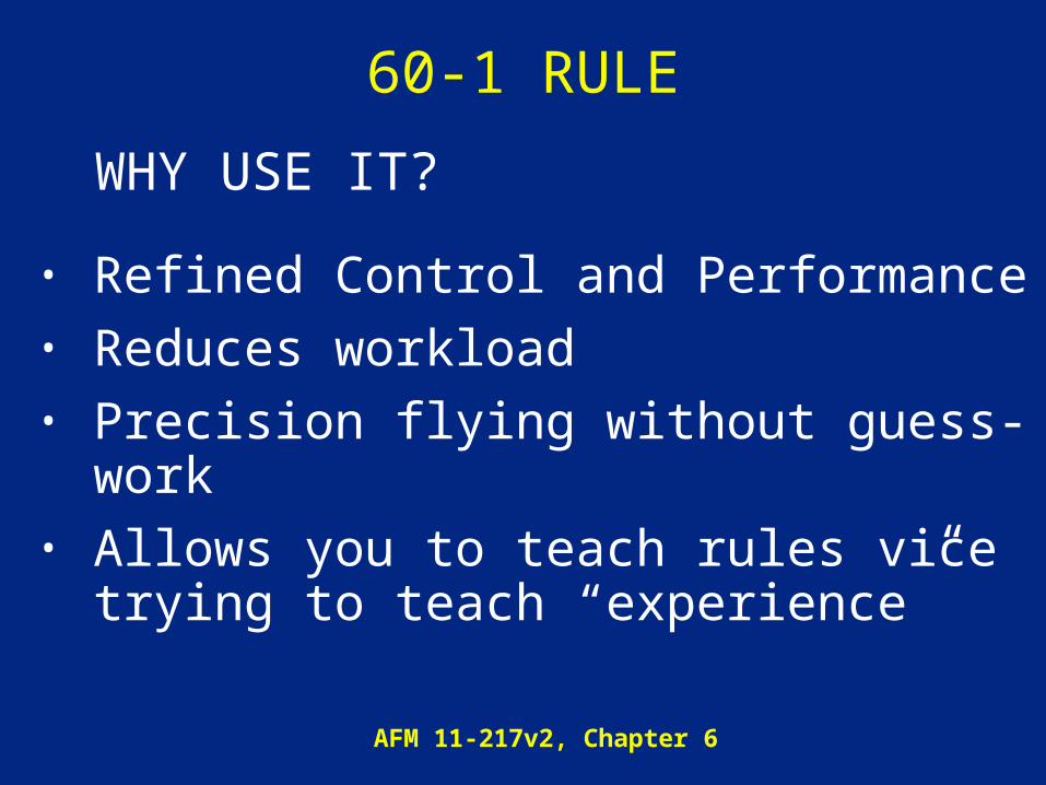
WHY USE IT?
• Refined Control and Performance• Reduces workload• Precision flying without guess-work• Allows you to teach rules vice trying to
teach “experience”
AFM 11-217v2, Chapter 6

WHEN to USE 60-1
• Pitch changes• Gradients to meet restrictions• Lead turns• Wind Corrections• Approaches • Holding Entries, Teardrop Penetrations
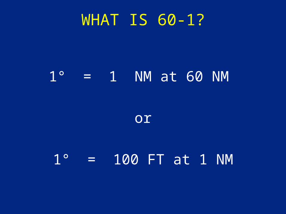
WHAT IS 60-1?
1° = 1 NM at 60 NM
or
1° = 100 FT at 1 NM
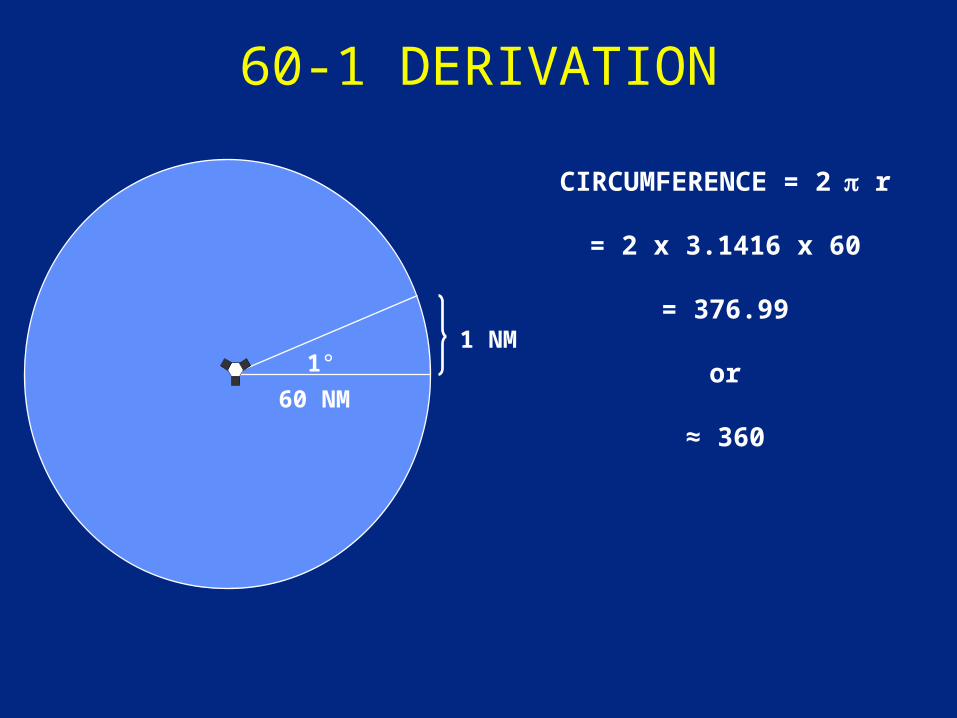
60-1 DERIVATION
60 NM
1°
CIRCUMFERENCE = 2 r
= 2 x 3.1416 x 60
= 376.99
or
≈ 360
1 NM
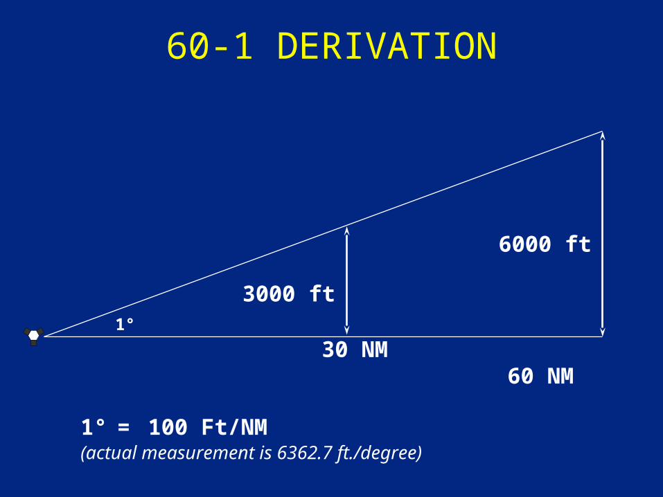
60-1 DERIVATION
30 NM 60 NM
3000 ft1°
1° = 100 Ft/NM(actual measurement is 6362.7 ft./degree)
6000 ft
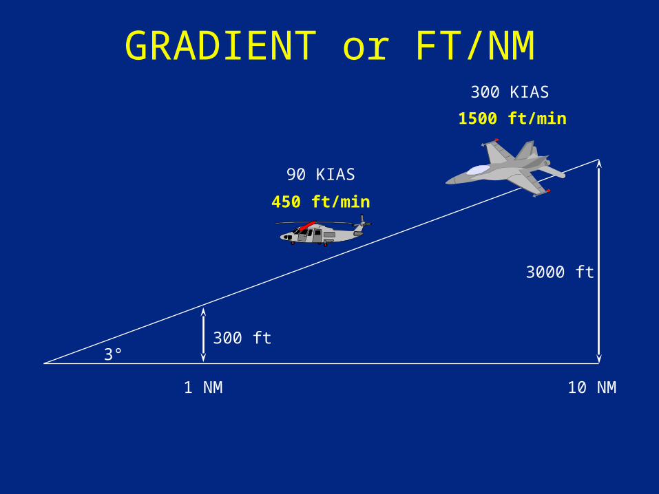
GRADIENT or FT/NM
3°300 ft
3000 ft
1 NM 10 NM
300 KIAS
90 KIAS
450 ft/min
1500 ft/min
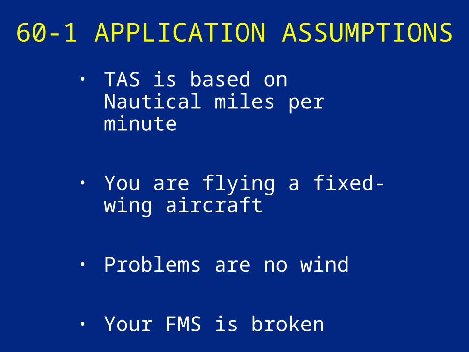
60-1 APPLICATION ASSUMPTIONS
• TAS is based on Nautical miles per minute
• You are flying a fixed-wing aircraft
• Problems are no wind
• Your FMS is broken
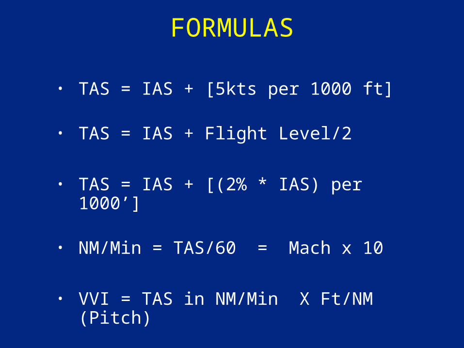
FORMULAS
• TAS = IAS + [5kts per 1000 ft]
• TAS = IAS + Flight Level/2
• TAS = IAS + [(2% * IAS) per 1000’]
• NM/Min = TAS/60 = Mach x 10
• VVI = TAS in NM/Min X Ft/NM (Pitch)
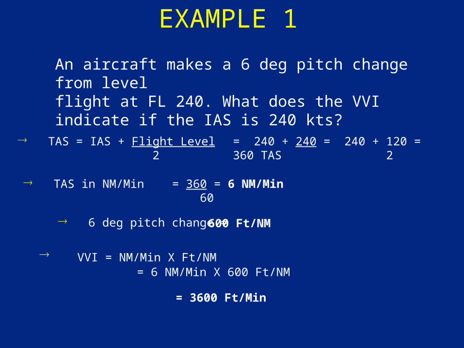
EXAMPLE 1
TAS = IAS + Flight Level 2
TAS in NM/Min
6 deg pitch change =
VVI = NM/Min X Ft/NM = 6 NM/Min X 600 Ft/NM
An aircraft makes a 6 deg pitch change from level flight at FL 240. What does the VVI indicate if the IAS is 240 kts?
= 240 + 240 = 240 + 120 = 360 TAS 2
= 360 = 6 NM/Min 60
600 Ft/NM
= 3600 Ft/Min
EXAMPLE 2
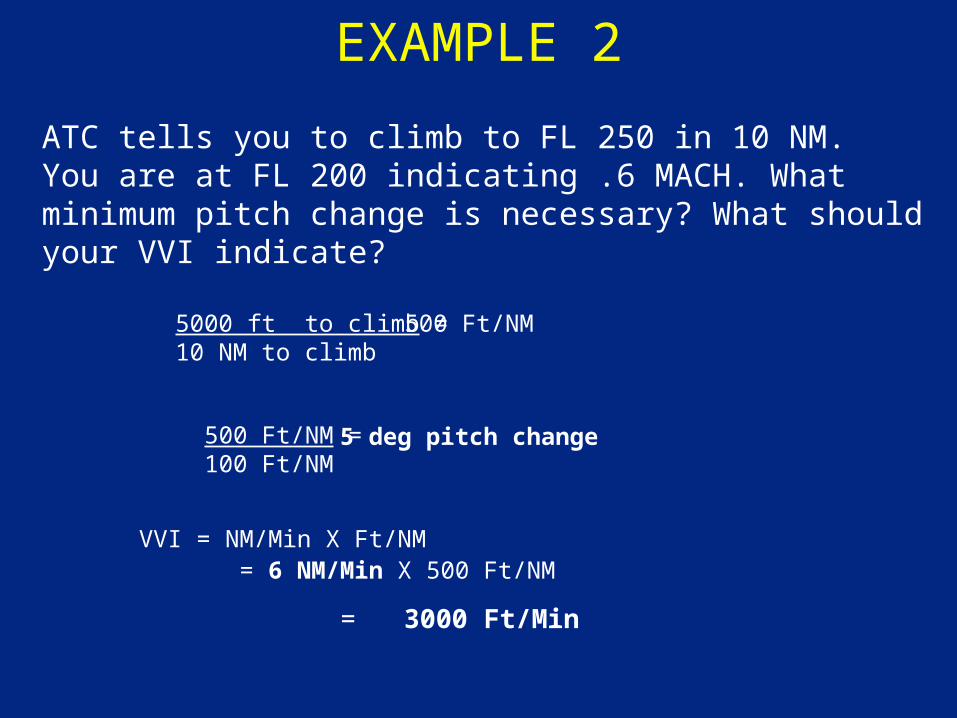
ATC tells you to climb to FL 250 in 10 NM. You are at FL 200 indicating .6 MACH. What minimum pitch change is necessary? What should your VVI indicate?
5000 ft to climb =10 NM to climb
500 Ft/NM =100 Ft/NM
VVI = NM/Min X Ft/NM = 6 NM/Min X 500 Ft/NM
500 Ft/NM
5 deg pitch change
= 3000 Ft/Min
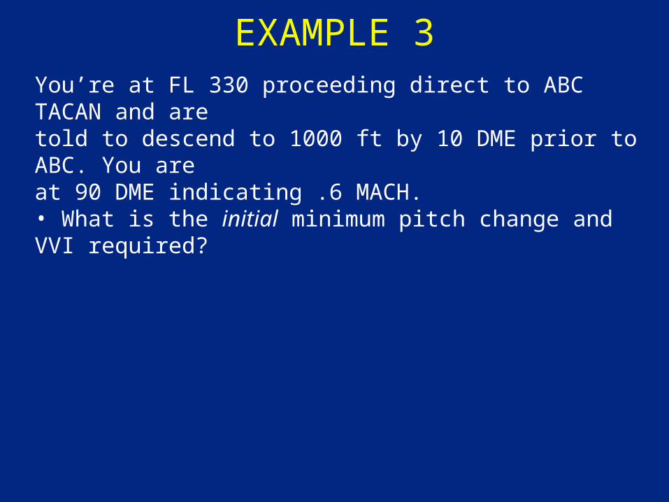
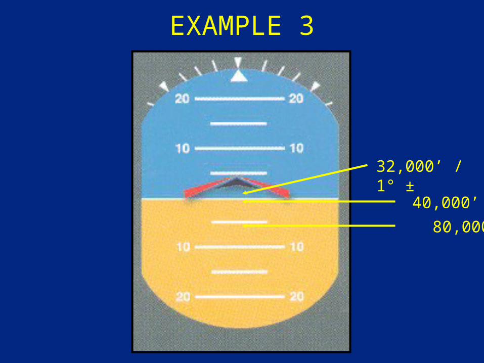
EXAMPLE 3You’re at FL 330 proceeding direct to ABC TACAN and are told to descend to 1000 ft by 10 DME prior to ABC. You are at 90 DME indicating .6 MACH.• What is the initial minimum pitch change and VVI required?
EXAMPLE 3
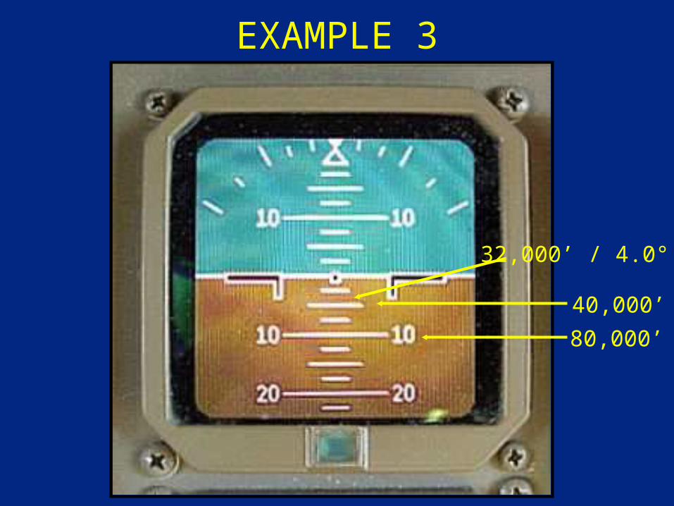
80,000’
40,000’
32,000’ / 4.0° ±
EXAMPLE 3
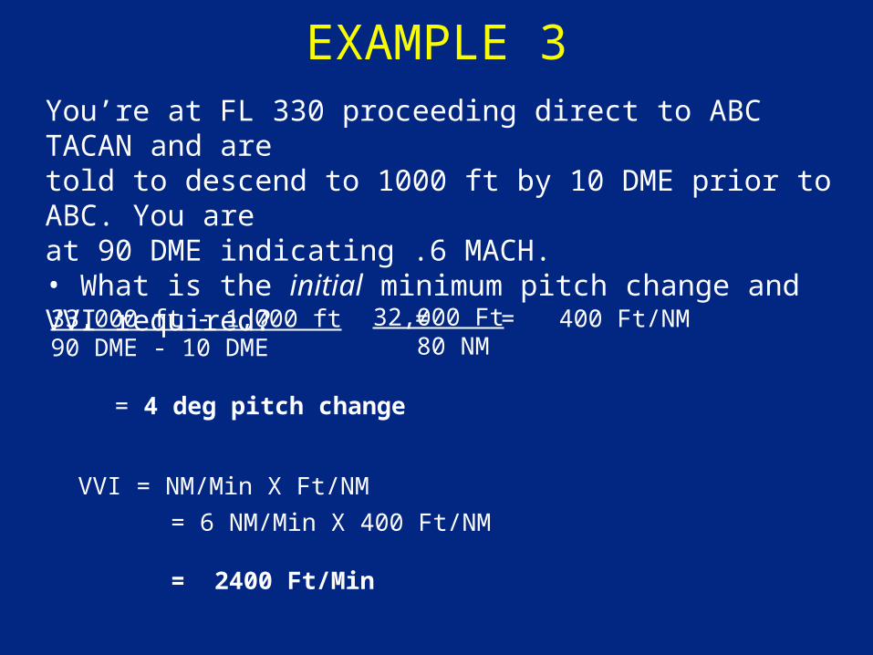
33,000 ft - 1,000 ft =90 DME - 10 DME
= 4 deg pitch change
VVI = NM/Min X Ft/NM
You’re at FL 330 proceeding direct to ABC TACAN and are told to descend to 1000 ft by 10 DME prior to ABC. You are at 90 DME indicating .6 MACH.• What is the initial minimum pitch change and VVI required?
32,000 Ft 80 NM
= 400 Ft/NM
= 6 NM/Min X 400 Ft/NM
= 2400 Ft/Min
EXAMPLE 3
80,000’
40,000’
32,000’ / 1° ±
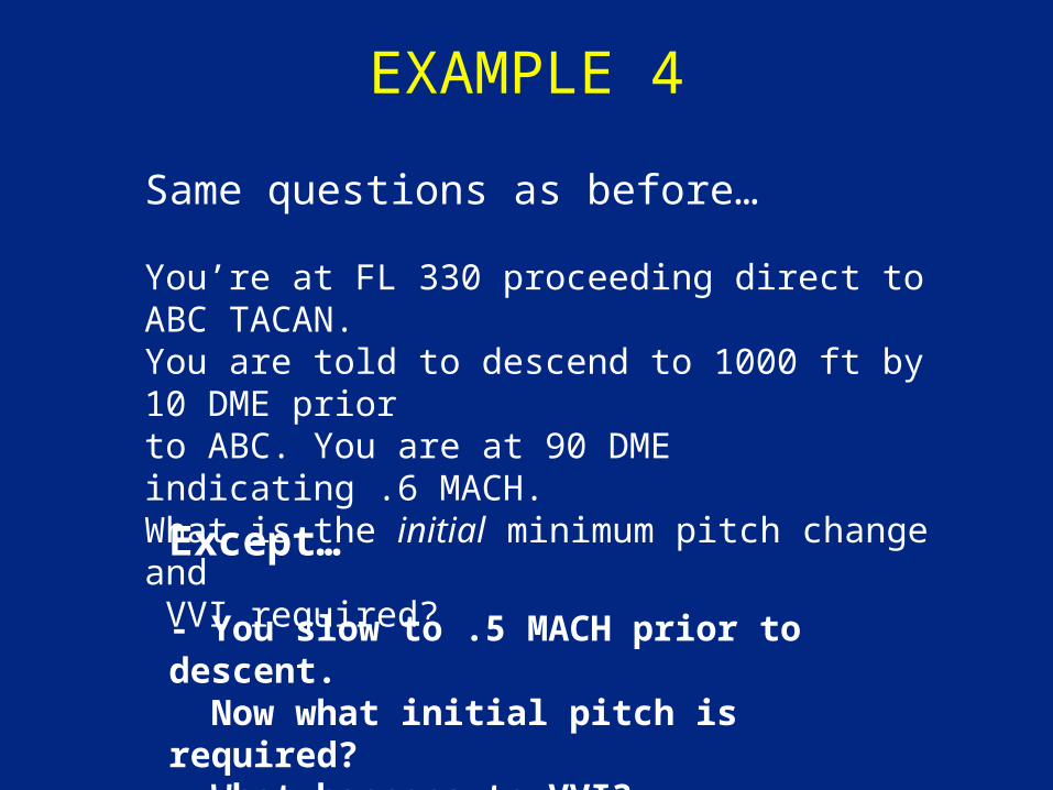
EXAMPLE 4
Same questions as before…
You’re at FL 330 proceeding direct to ABC TACAN.You are told to descend to 1000 ft by 10 DME priorto ABC. You are at 90 DME indicating .6 MACH.What is the initial minimum pitch change and VVI required?
Except…
- You slow to .5 MACH prior to descent. Now what initial pitch is required?- What happens to VVI?
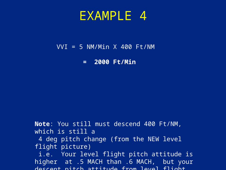
EXAMPLE 4
VVI = 5 NM/Min X 400 Ft/NM
= 2000 Ft/Min
Note: You still must descend 400 Ft/NM, which is still a 4 deg pitch change (from the NEW level flight picture) i.e. Your level flight pitch attitude is higher at .5 MACH than .6 MACH, but your descent pitch attitude from level flight will not change. (still 400 Ft/NM )

WINDS
• How do winds affect the gradient?
• Will it affect the VVI?
EXAMPLE 6
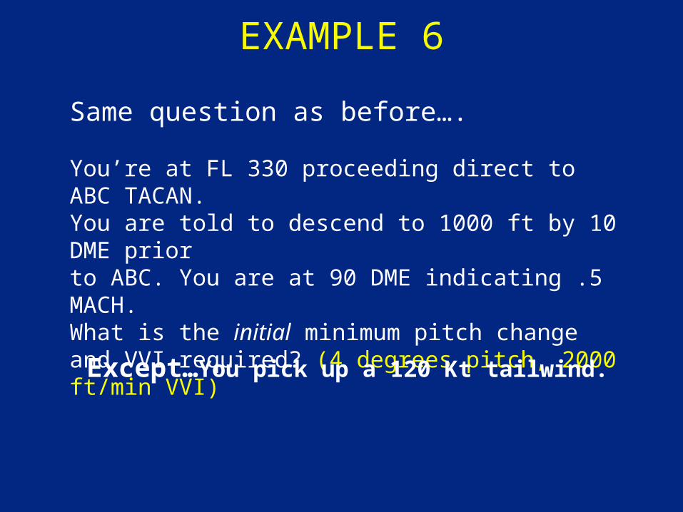
Same question as before….
You’re at FL 330 proceeding direct to ABC TACAN.You are told to descend to 1000 ft by 10 DME priorto ABC. You are at 90 DME indicating .5 MACH.What is the initial minimum pitch change and VVI required? (4 degrees pitch, 2000 ft/min VVI)
Except…You pick up a 120 Kt tailwind.
EXAMPLE 6
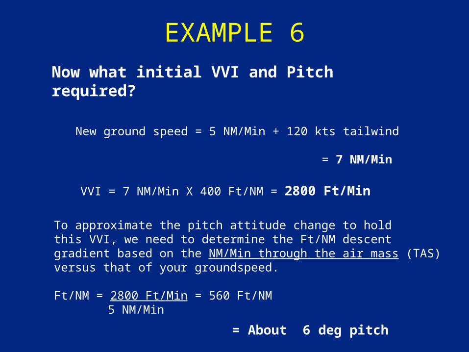
New ground speed = 5 NM/Min + 120 kts tailwind
= 7 NM/Min
VVI = 7 NM/Min X 400 Ft/NM = 2800 Ft/Min
To approximate the pitch attitude change to holdthis VVI, we need to determine the Ft/NM descent gradient based on the NM/Min through the air mass (TAS)versus that of your groundspeed.
Ft/NM = 2800 Ft/Min = 560 Ft/NM 5 NM/Min
= About 6 deg pitch
Now what initial VVI and Pitch required?
GOOD RULE OF THUMB
• Add/subtract one degree of pitch for every 60 knots of tailwind/headwind
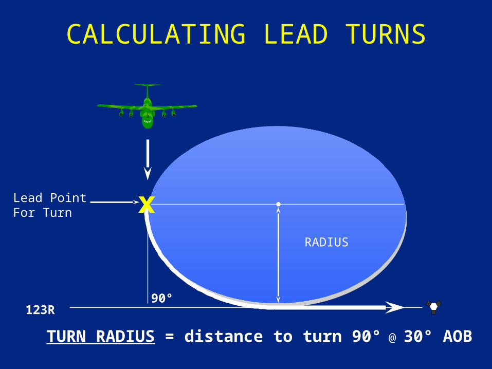
CALCULATING LEAD TURNS
RADIUS
Lead PointFor Turn
90°
TURN RADIUS = distance to turn 90° @ 30° AOB
123R
x
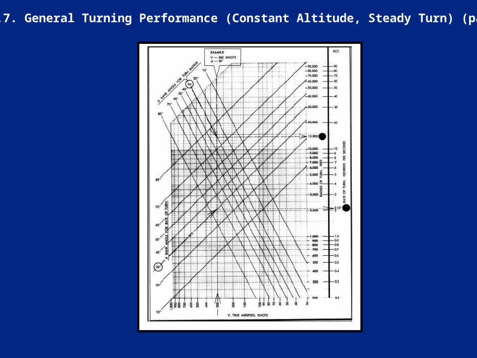
Figure 20.7. General Turning Performance (Constant Altitude, Steady Turn) (para 20.5).
AIRCRAFT TURN RADIUS
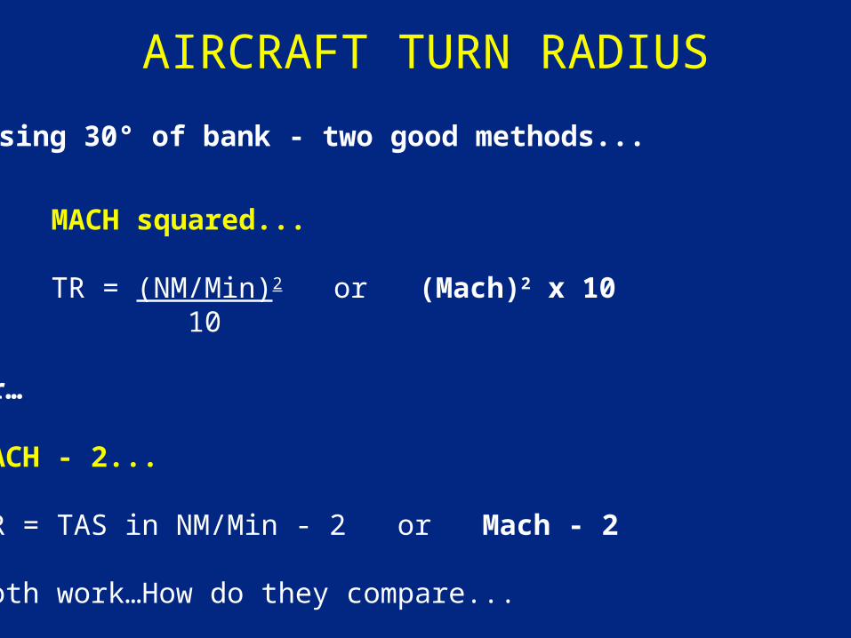
MACH squared...
TR = (NM/Min)2 or (Mach)2 x 10 10
or…
MACH - 2...
TR = TAS in NM/Min - 2 or Mach - 2
Both work…How do they compare...
Using 30° of bank - two good methods...
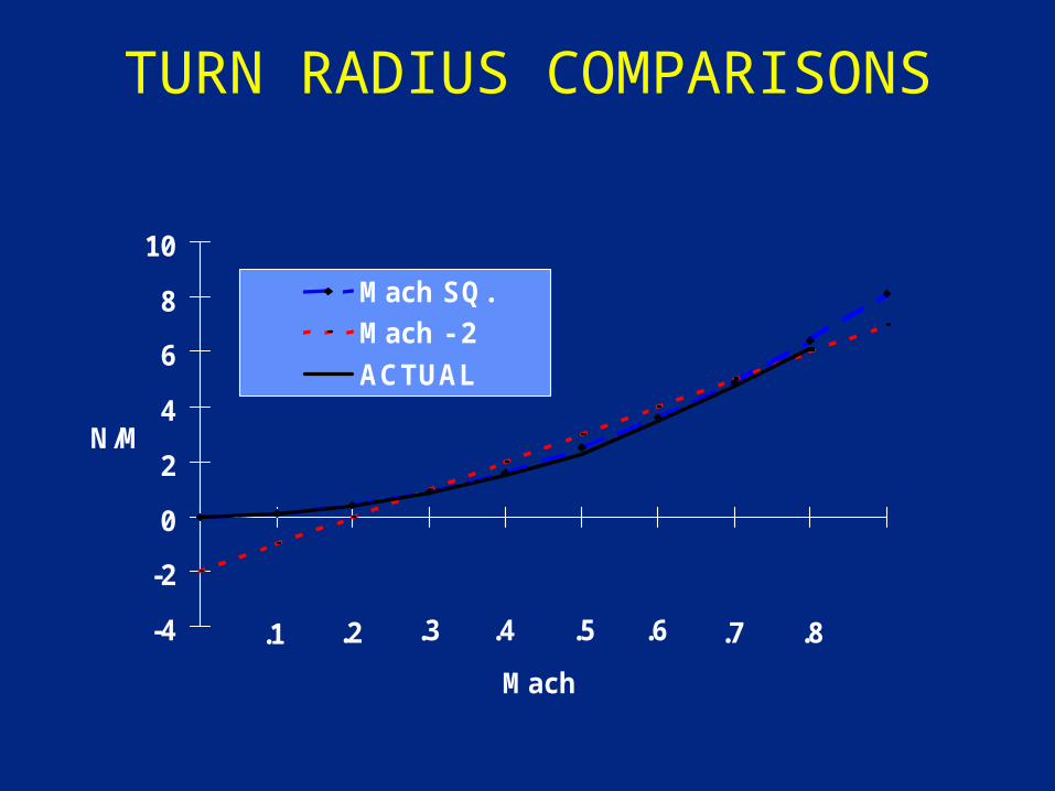
TURN RADIUS COMPARISONS
-4
-2
0
2
4
6
8
10
Mach
N/M
Mach SQ.
Mach - 2
ACTUAL
.1 .2 .3 .4 .5 .6 .7 .8
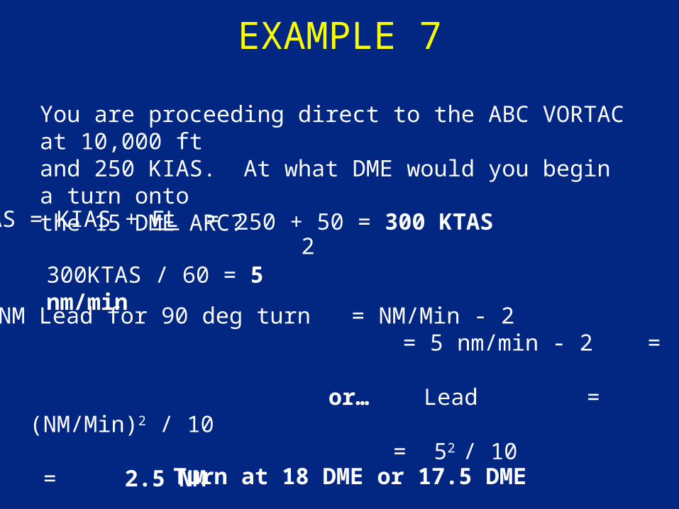
EXAMPLE 7
You are proceeding direct to the ABC VORTAC at 10,000 ftand 250 KIAS. At what DME would you begin a turn ontothe 15 DME ARC?
or… Lead = (NM/Min)2 / 10 = 52 / 10 = 2.5 NM
TAS = KIAS + FL = 2300KTAS / 60 = 5 nm/min
NM Lead for 90 deg turn = NM/Min - 2
Turn at 18 DME or 17.5 DME
250 + 50 = 300 KTAS
= 5 nm/min - 2 = 3NM
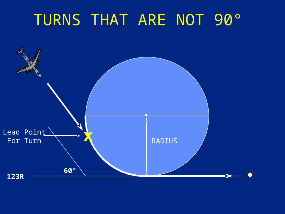
TURNS THAT ARE NOT 90°
RADIUSLead PointFor Turn
60°123R
x
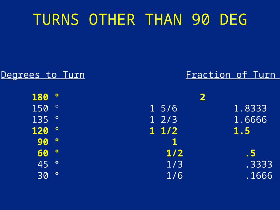
TURNS OTHER THAN 90 DEG
Degrees to Turn Fraction of Turn Radius
180 ° 2 150 ° 1 5/6 1.8333 135 ° 1 2/3 1.6666 120 ° 1 1/2 1.5 90 ° 1 60 ° 1/2 .5 45 ° 1/3 .3333 30 ° 1/6 .1666
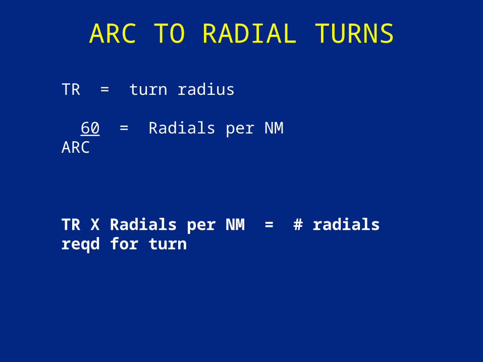
ARC TO RADIAL TURNS
TR = turn radius
60 = Radials per NMARC
TR X Radials per NM = # radials reqd for turn
TR = NM/Min - 2
Number of lead RADIALS = TR X 60 ARC
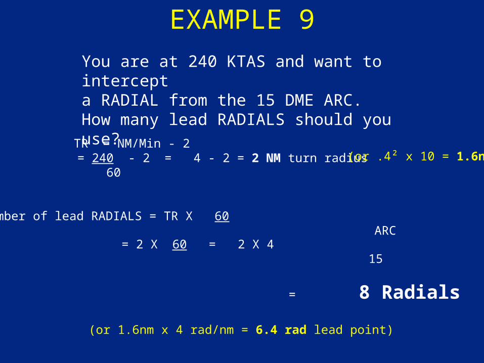
EXAMPLE 9
You are at 240 KTAS and want to intercepta RADIAL from the 15 DME ARC. How many lead RADIALS should you use?
= 240 - 2 = 4 - 2 = 2 NM turn radius 60
(or .4² x 10 = 1.6nm)
= 2 X 60 = 2 X 4 15
= 8 Radials
(or 1.6nm x 4 rad/nm = 6.4 rad lead point)
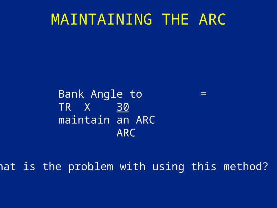
MAINTAINING THE ARC
Bank Angle to = TR X 30maintain an ARC ARC
What is the problem with using this method?
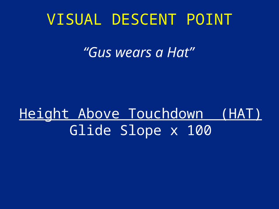
VISUAL DESCENT POINT
Height Above Touchdown (HAT)Glide Slope x 100
“Gus wears a Hat”
VORTAC
2500
4000 273JACKK
2.4 NM .2
MISSED APPROACHGo Home
CATEGORY
S-27
CIRCLING
2200/24 411 (500-1/2) 2200/40 411 (500-3/4) 2200/50411(500-1)
2280-1 491 (500-1)2280-1 1/2491 (500-1 1/2)
2340-2551 (600-2)
2400-2 1/4611 (700-2 1/4)
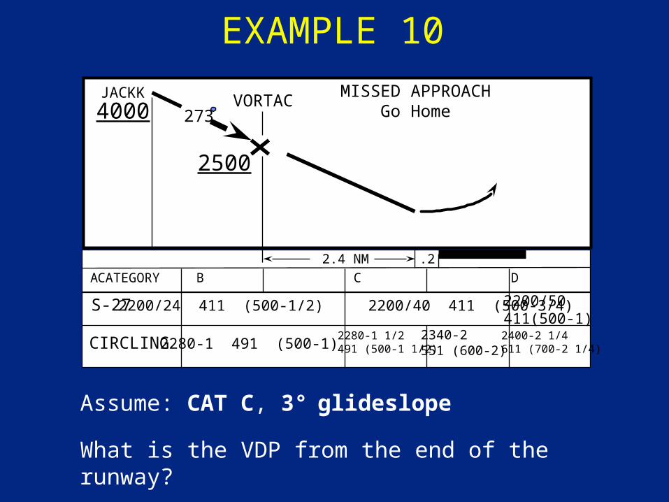
Assume: CAT C, 3° glideslope
What is the VDP from the end of the runway?
EXAMPLE 10
A B C D E
VORTAC
2500
4000 273JACKK
2.4 NM .2
MISSED APPROACHGo Home
CATEGORY
S-27
CIRCLING
2200/50411(500-1)
2280-1 491 (500-1)2280-1 1/2491 (500-1 1/2)
2340-2551 (600-2)
2400-2 1/4611 (700-2 1/4)
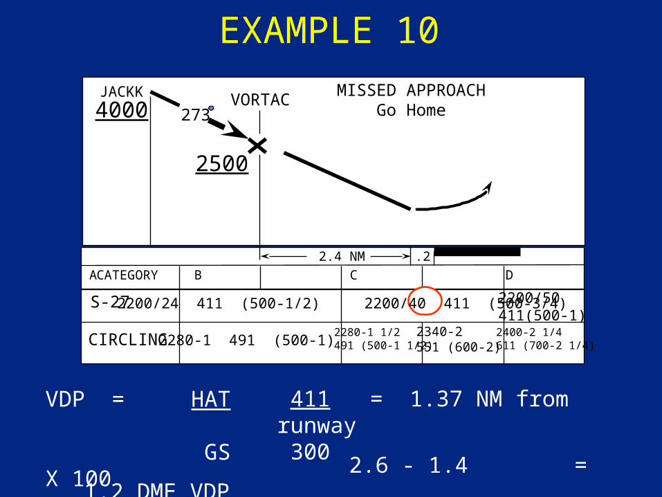
VDP = HAT GS X 100
EXAMPLE 10
A B C D E
411 = 1.37 NM from runway 300
2.6 - 1.4 = 1.2 DME VDP
2200/24 411 (500-1/2) 2200/40 411 (500-3/4)
BE CAREFUL THOUGH…
• Why would the TERPster not depict a VDP?
• Bottom line: After departing the MDA, obstacle clearance is pilot’s responsibility!
PROCEDURES & TECHNIQUES
• Instrument Cross-check• 60 - 1 Rule• Climbs and Descents• Turns and Intercepts• Other Applications• Sources:
• AFMAN 11-217v1, Chapter 1 & Chapter 20 (all)• AFMAN 11-217v2, Chapter 6 (all)• AFI 11-202v3: 2.6 – 2.6.1.3.1
QUESTION
Control Instruments:
A. indicate actual aircraft performance in relation to the air mass
B. are the ADI, power indicator, altimeter, and airspeed indicator
C. display immediate attitude and power indications
D. indicate the position of the aircraft in relation to a selected navigation fix
QUESTION
Your departure procedure requires a climb gradient of 400 ft/nm and your planned climbout speed is 300 KTAS. What minimum pitch change should you use and what would be the resulting VVI?
A. 6 Degrees, 1800 Ft/MinB. not enough information is givenC. 4 Degrees, 1200 Ft/MinD. 4 Degrees, 2000 Ft/Min
QUESTION
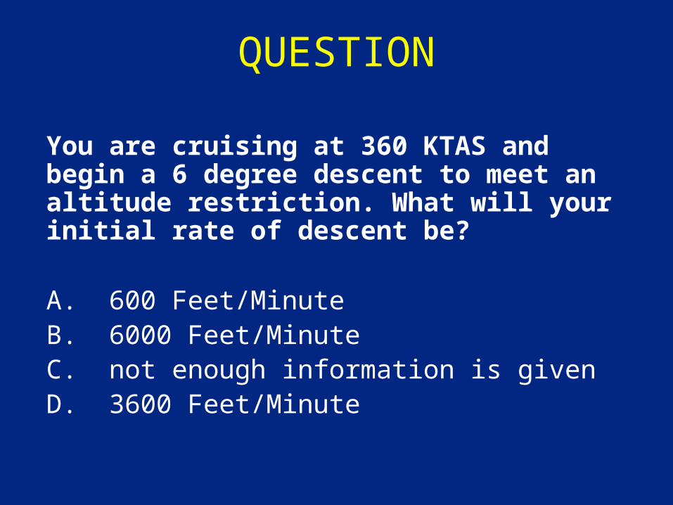
You are cruising at 360 KTAS and begin a 6 degree descent to meet an altitude restriction. What will your initial rate of descent be?
A. 600 Feet/MinuteB. 6000 Feet/MinuteC. not enough information is givenD. 3600 Feet/Minute
QUESTION
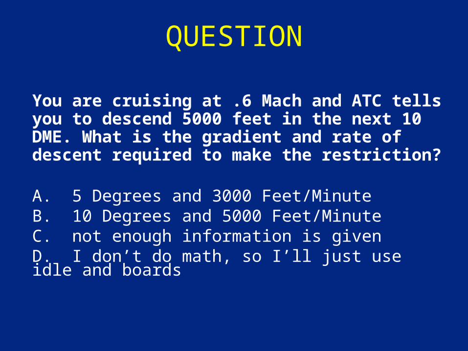
You are cruising at .6 Mach and ATC tells you to descend 5000 feet in the next 10 DME. What is the gradient and rate of descent required to make the restriction?
A. 5 Degrees and 3000 Feet/Minute B. 10 Degrees and 5000 Feet/MinuteC. not enough information is givenD. I don’t do math, so I’ll just use idle and boards
QUESTION
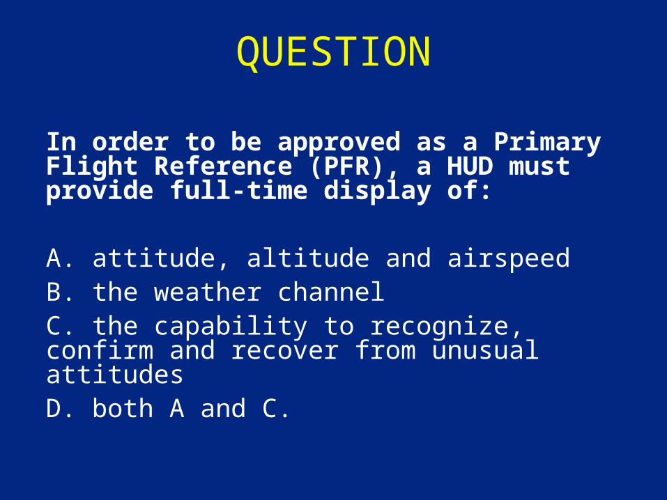
In order to be approved as a Primary Flight Reference (PFR), a HUD must provide full-time display of:
A. attitude, altitude and airspeedB. the weather channelC. the capability to recognize, confirm and recover from unusual attitudesD. both A and C.

CRITIQUES