air diaphragm pumps
DESCRIPTION
Air Driven Double Diaphragm Pumps. www.pumpac.comTRANSCRIPT
Air Driven Double Diaphragm
Pumps
The BEST Diaphragm Pumps in the World!
PUMPAC
ABOUTPUMPAC
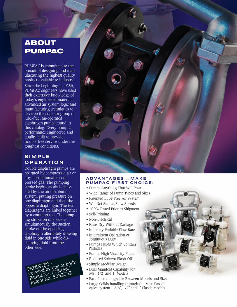
PUMPAC is committed to thepursuit of designing and man-ufacturing the highest qualityproduct available to industry. Since the beginning in 1986,PUMPAC engineers have usedtheir extensive knowledge oftoday’s engineered materials,advanced air system logic andmanufacturing techniques todevelop the superior group oflube-free, air-operateddiaphragm pumps found inthis catalog. Every pump isperformance engineered andquality built to provide trouble-free service under thetoughest conditions.
S I M P L E O P E R A T I O NDouble diaphragm pumps areoperated by compressed air orany non-flammable com-pressed gas. The pumpingstroke begins as air is deliv-ered by the air distributionsystem, putting pressure onone diaphragm and then theopposite diaphragm. The twodiaphragms are linked togetherby a common rod. The pump-ing stroke on one side issimultaneously the suctionstroke on the opposingdiaphragm alternately drawingfluid in one side while dis-charging fluid from the other side.
PATENTED -
Covered by one or both:
Patent No. 5758563
Patent No. 5232352
A D V A N T A G E S . . . M A K E P U M P A C F I R S T C H O I C E :• Pumps Anything That Will Pour• Wide Range of Pump Types and Sizes• Patented Lube-Free Air System• Will Not Stall at Slow Speeds• 100% Tested Prior to Shipment• Self-Priming• Non-Electrical • Runs Dry Without Damage• Infinitely Variable Flow Rate• Intermittent Operation or
Continuous Duty• Pumps Fluids Which Contain
Particles• Pumps High Viscosity Fluids• Reduced Solvent Flash-Off• Simple Modular Design• Dual Manifold Capability for
3/8˝, 1/2˝ and 1˝ Models• Parts Interchangeable Between Models and Sizes• Large Solids handling through the Max-Pass™
valve system – 3/8˝, 1/2˝ and 1˝ Plastic Models
PERFORMANCE ENGINEERED
PUMPAC HAS THE RIGHT PUMPFOR ANY APPLICATION...Classic Performance pumps offeryears of trouble-free service.Performance Plus pumps offertrouble-free service plus enhancedoperating features.The Specialty Performance 3/8˝pump – the revolution in low flowpump technology.
NO STALLOUTS DUE TO FREEZING...Stallout due to ice formation in theair system is virtually eliminateddue to the insulating quality of allplastic construction plus the abilityto slow air expansion and velocitywithout compromising performance.
NO VENT HOLES...There are no vent holes in the PUMPACair valve. Vent holes needed to pre-vent stalling in competitive pumpsallow corrosive fumes to enter anddestroy valuable components.Additionally, if a diaphragm ruptures,fluid leakage cannot be routed to asafe containment zone. The sealedPUMPAC air valve allows contain-ment of fluid and prevents fumesfrom entering air system.
PERFORMANCE ENGINEEREDPTFE DESIGN...Superior PTFE overlay design doesNOT require reduced diaphragm rodstroke, which reduces pump capacityby 20% on competitive pumps. Allback-up diaphragms for PTFE over-lays are Santoprene which offers achemically resistant “second line ofdefense”.
THERMOPLASTIC DIAPHRAGMS...offer superior chem-ical and abrasionresistance andincreased cycle life.The wide range ofapplications thatthese materials canaddress also make
ordering the correct pump much easier.
MAINTENANCE TIME REDUCED...due to uniform product design. Allmodels share the same design conceptfrom 1/2˝ pumps to 3˝ pumps. Thesize of the components just get larger.If you know how to rebuild one size...you can easily rebuild any size.
INVENTORY REDUCTION...because metallic and plastic pumpsall share the same air systems,diaphragms, O-rings, balls and insome cases valve seats. To furtherhelp minimize inventory requirements,1-1/2˝ and 2˝ models share the sameair systems, diaphragms and valveseat components.
ALL PLASTIC AIR SYSTEMS...in both metallic and plastic pumps prevent destruction of air system components from corrosive atmos-pheres or diaphragm ruptures. Nobrass or aluminum components areused within the air systems.
SIMPLE ORDERING CODES...confused by complex ordering codesrequired by some manufacturers—not with PUMPAC. All models areeasily associated with materials andhave a simplified model number asshown on page 4.
MAX-PASS™ VALVE SYSTEM FOR LARGE SOLIDS...
Look for the Max-Pass™ symbol.
LARGER CAPACITY...per stroke than competitive modelsmeans less wear on moving parts.
BSP...compatibility is accomplished throughthe use of slotted flanges on the 1˝,1-1/2˝ and 2˝ models and BSP com-patible threads are available on othermodels when requested.
PROCESS CONTROL...Solenoid Control is optional forSpecialty Performance andPerformance Plus pumps. Cyclecounting is optional for most pumps.
ATEX AND CE...certification and quality control proce-dures have been obtained for all models.
3P U M P A C
P A T E N T E D L U B E - F R E E ,
N O N - S T A L L I N G A I R S Y S T E M
T H E H E A R T O F T H E P U M P . . .gives reliable, trouble-free operation in all sizes of pumps.
Competitive pumps claim lube-freeoperation, but operation manuals notethat lubrication is always needed during “certain operating conditions.”PUMPAC’s air system is truly lube-freeand will not stall at slow speeds.
L U B E - F R E E O P E R A T I O N . . .throughout the life of the pump is achieved by using dissimilar plastic materials within the air system and a shuttle mechanism constructed of lubrication filled materialsto maximize lubricity. Flatness and surface finishes are heldto strict engineering tolerances which also reduce the coefficient of friction resulting in trouble-free operation and increased air efficiency.
N O A I R L O S T . . .when fluid discharge lines are closed. Air system sealscompletely and prevents air consumption when pump is not transferring fluid. The low coefficient of frictionbetween the air system components also helps reduce air consumption.
A L L P L A S T I C A I R S Y S T E M S U S E D I N B O T H
M E T A L L I C A N D P L A S T I C . . .pumps are corrosion resistant and will not be destroyed incase of diaphragm rupture, spills or corrosive atmospheres.
S T A T E - O F - T H E - A R T S E A L T E C H N O L O G Y U S E D
I N T H E A I R S Y S T E M . . .is more tolerant of dirty and wet air supplies. Lip seals andhigh wear elastomers offer outstanding cycle life.
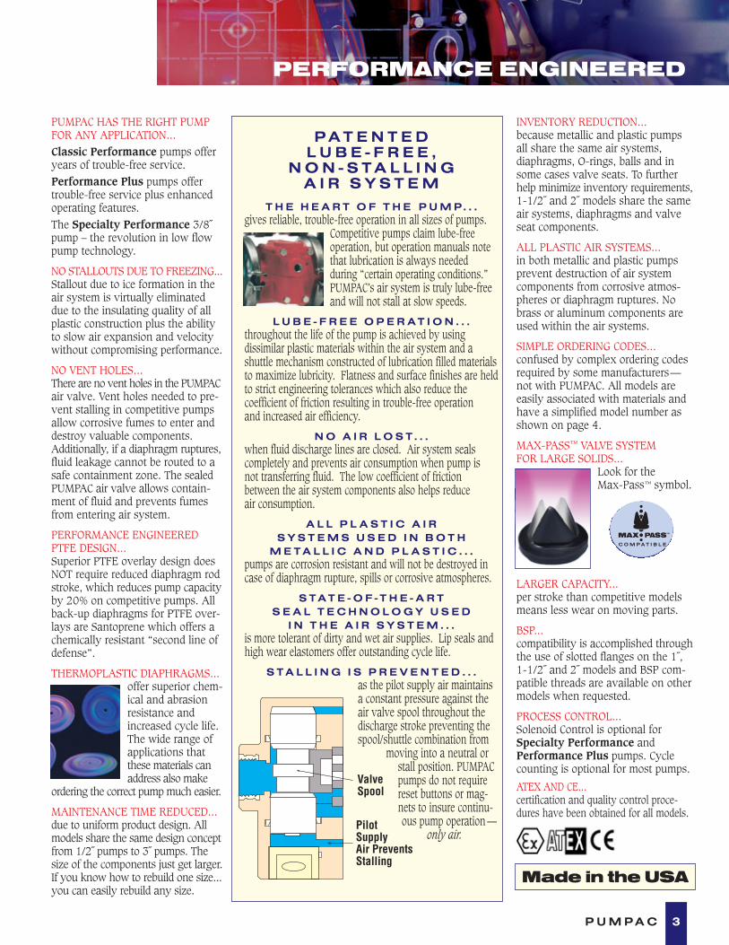
S T A L L I N G I S P R E V E N T E D . . .as the pilot supply air maintainsa constant pressure against theair valve spool throughout thedischarge stroke preventing thespool/shuttle combination from
moving into a neutral orstall position. PUMPACpumps do not requirereset buttons or mag-nets to insure continu-ous pump operation ––
only air.
ValveSpool
PilotSupplyAir PreventsStalling
Made in the USA

MATERIALS OF CONSTRUCTION
4 P U M P A C
DIAPHRAGM NOTES• Geolast® is a nitrile based thermoplastic elastomer used in place of nitrile (Buna-N)
or neoprene and urethane for non-aggressive water-based applications.• Santoprene® is an EPDM-based thermoplastic elastomer and is resistant to mild
acids, some solvents and bases.• PTFE–stock models feature a two part diaphragm system in pumps 1/2˝
and larger.
Fluid Chambers Diaphragms Valve/Ball Valve Seats O-Rings Fasteners1/4˝ Classic Performance ModelsNC-025 Polypropylene Geolast®3 PTFE Polypropylene Nitrile SS2
NC-025E Polypropylene Santoprene®3 PTFE Polypropylene EPDM SSBK-025 Polypropylene PTFE PTFE Polypropylene PTFE SSRD-025 Nylon PTFE PTFE Nylon PTFE SSRD-025B Nylon Geolast® PTFE Nylon Nitrile SSCN-025 Conductive Nylon PTFE PTFE Nylon PTFE SSCN-025B Conductive Nylon Geolast® PTFE Nylon Geolast® SSKN-025 PVDF PTFE PTFE PVDF PTFE SSKN-025E PVDF Santoprene® PTFE PVDF EPDM SS3/8˝ Specialty Performance Plastic ModelsPB-038 Polypropylene Geolast® Nitrile Max-Pass™ N/A Nitrile SS2
PE-038 Polypropylene Santoprene® EPDM Max-Pass™ N/A EPDM SSPT-038 Polypropylene PTFE PTFE Polypropylene PTFE SSPV-038 Polypropylene PTFE Viton® Max-Pass™ N/A Viton® SSKE-038 PVDF Santoprene® EPDM Max-Pass™ N/A EPDM SSKT-038 PVDF PTFE PTFE PVDF PTFE SSKV-038 PVDF PTFE Viton® Max-Pass™ N/A Viton® SSCT-038 Conductive Nylon PTFE PTFE SS PTFE SSCB-038 Conductive Nylon Geolast® Nitrile Max-Pass™ N/A Nitrile SSCV-038 Conductive Nylon PTFE Viton® Max-Pass™ N/A Viton® SS1/2˝ & 1˝ Performance Plus Models
PB-05 PB-10 Polypropylene Geolast® Geolast® Polypropylene Nitrile SS2
PE-05 PE-10 Polypropylene Santoprene® Santoprene® Polypropylene EPDM SSPT-05 PT-10 Polypropylene PTFE PTFE Polypropylene PTFE SSPV-05 PV-10 Polypropylene Viton® Viton® Polypropylene Viton® SSNB-05 Nylon Geolast® Geolast® PVDF Nitrile SSNT-05 Nylon PTFE PTFE PVDF PTFE SSNV-05 Nylon Viton® Viton® PVDF Viton® SSCT-05 Conductive Nylon PTFE PTFE SS PTFE SSCB-05 Conductive Nylon Geolast® Geolast® SS Nitrile SSCV-05 Conductive Nylon Viton® Viton® SS Viton® SSKT-05 KT-10 PVDF PTFE PTFE PVDF PTFE SSKE-05 KE-10 PVDF Santoprene® Santoprene® PVDF EPDM SSKV-05 KV-10 PVDF Viton® Viton® PVDF Viton® SSAB-05 AB-10 Aluminum Geolast® Geolast® Polypropylene Nitrile SS AE-05 AE-10 Aluminum Santoprene® Santoprene® Polypropylene EPDM SSAT-05 AT-10 Aluminum PTFE PTFE Nylon PTFE SSAV-05 AV-10 Aluminum Viton® Viton® Nylon Viton® SSSB-05 SB-10 316 SS Geolast® Geolast® SS Nitrile SSSE-05 SE-10 316 SS Santoprene® Santoprene® SS EPDM SSSP-05 SP-10 316 SS PTFE PTFE SS PTFE SSSV-05 SV-10 316 SS Viton® Viton® SS Viton® SS
1/2˝& 1˝ Classic Performance Plastic ModelsNC-5 NC-103 Polypropylene Geolast® Geolast® Polypropylene Nitrile SS and PS3
BK-5 BK-103 Polypropylene PTFE PTFE Polypropylene PTFE SSBK-5E BK-10E3 Polypropylene Santoprene® Santoprene® Polypropylene EPDM SSBK-5V BK-10V3 Polypropylene Viton® Viton® Polypropylene Viton® SSKN-5 KN-10 PVDF PTFE PTFE PVDF PTFE SSKN-5E KN-10E PVDF Santoprene® Santoprene® PVDF EPDM SSKN-5V KN-10V PVDF Viton® Viton® PVDF Viton® SS1-1/2˝, 2˝ & 3˝ Performance Plus Models
PB-15 PB-20 Polypropylene Geolast® Geolast® Polypropylene Nitrile SS2
PT-15 PT-20 Polypropylene PTFE PTFE Polypropylene PTFE SSPE-15 PE-20 Polypropylene Santoprene® Santoprene® Polypropylene EPDM SSKT-15 KT-20 PVDF PTFE PTFE PVDF PTFE SSKE-15 KE-20 PVDF Santoprene® Santoprene® PVDF EPDM SSAB-15 AB-20 Aluminum Geolast® Geolast® Polypropylene Nitrile SSAE-15 AE-20 Aluminum Santoprene® Santoprene® Polypropylene EPDM SSAT-15 AT-20 Aluminum PTFE PTFE Nylon PTFE SSSB-15 SB-20 316 SS Geolast® Geolast® SS Nitrile SSSE-15 SE-20 316 SS Santoprene® Santoprene® SS EPDM SSSP-15 SP-20 316 SS PTFE PTFE SS PTFE SS
AL-30 Aluminum Urethane Geolast® Nitrile N/A SS and PSAL-30E Aluminum Santoprene® Santoprene® EPDM N/A SS and PSAL-30T Aluminum PTFE PTFE Nylon PTFE SS and PSAL-30V Aluminum Viton® Viton® Viton® N/A SS and PS
NOTES1 PS = Plated Steel2 SS = Stainless Steel3 Glass-filled polypropylene• Santoprene® and Geolast® are registered trademarks of Advanced Elastomer Systems.• Viton® is a registered trademark of DuPont Dow Elastomers.• All air systems are glass-filled polypropylene.

SELECTION GUIDE
As you can see from the diagram above, as viscositiesincrease, the capacity of the pump decreases. Do notexceed 22,000 centapoise or 100,000 saybolt seconds onall 3/8˝ up to 3˝ pumps. Do not exceed 4,000 centapoise or18,000 saybolt seconds on 1/4˝ models.
Some points to remember when pumping high viscosities:
1. Position the pump close to or below the level of the fluid source.
2. Suction lines should be increased in size—up to threetimes the size of the pump manifold inlet. Dual manifoldsmay be used when available.
3. Start the pump slowly using a control valve on the air line.
4. Maximum air pressure required is reached when increasing the air pressure does not increase the flow rate.
5. If greater capacity is required, select a larger pump.
READING THE PUMP CURVEYou must know the following data:1. Required discharge pressure.2. Air pressure available at the
air inlet of the pump.3. Required flow rate.
TO OBTAIN DISCHARGE PRESSURE:Using the performance chart for a 1/2˝pump shown: If 80 psi is available at theair inlet and the required capacity of thepump is 6 GPM. Follow the blue concavecurve at 80 psi as it slopes to the rightand intersects with the 6 GPM vertical line
By tracking horizontally back to the left(Y) axis, the discharge pressure is ascer-tained—65 psi . (Right axis convertsPSI to feet/meters).
TO OBTAIN REQUIRED AIR INLETPRESSURE:Reverse the steps above:Choose required discharge pressure (65 psi) on left (Y) axis,go directly across the graph to the intersection of the correct flowrate (6 GPM) , then track up and back toward the left (Y) axisalong the blue curve; and the correct required air pressure can beobtained (80 psi).Note: If greater outlet pressure vs. air inlet pressure is required—select a larger pump.
TO OBTAIN AIR CONSUMPTION:The convex red lines represent the air consumption (standardcubic feet per minute), and the closest red line to where the blueline and the flow rate intersect represents the air capacityrequired. On our example, the air consumption would be approximately 6 SCFM.
To convert SCFM to m3/h (N) multiply by 1.7
0 6 102
DISCHARGE FLOW-Liters/Min.7,6 15,2 60,8
20(1,3)
40(2,7)
60(4,1)
80(5,4)
100(6,8)
230(69,9)
184(55,9)
138(41,9)
92(27,9)
46(13,9)
TOTA
L H
EA
D IN
FE
ET
(M
ET
ER
S)
PR
ES
SU
RE
INL
ET
/OU
TL
ET
PS
IG (
BA
R)
15
52 10
DISCHARGE FLOW-U.S. Gals./Min (GPM)
53,222,8 30,4 45,638,0
4 8 12 14 16
AIR CONSUMPTION - SCFM
123
INSTALLATION1. A lube-free, clean, dry compressed air source (or any non-flammable, compressed gas) is recommended. Use a filter thatis capable of filtering out particles larger than 50 microns.
2. Pumps should be mounted in an upright position with theexception of the 1/4˝ models or any pump with Max-Pass™
valves. These pumps can be mounted in any position.
3. Install a particle fluid filter on the fluid suction line whenparticles in the fluid exceed the maximum particle size specifi-cation of the pump or particles are sharp enough to cut thediaphragms.
4. Never restrict fluid suction lines by means of a reduced pipesize (smaller than pump inlet size) or control the pump withvalves on the fluid inlet side of the pump.
5. Limit fluid inlet pressure to 10 PSIG or (.68 BAR)
Performance Chart
20,000
20%
40%
60%
80%
100%
Centapoise
Saybolt Seconds40,000 60,000 80,000 100,000
2,000 4,000 6,000 8,000 10,000 12,000 14,000 16,000 18,000 20,000 22,000
Ca
pa
cit
y
5P U M P A C
1
2
2
3
3
2
1
HIGH VISCOSITY APPLICATIONS

6 P U M P A C
CLASSIC PERFORMANCE
0 2 3 4 51
DISCHARGE FLOW-Liters/Min.3,8 7,6 11,4 15,2 19,0
20(1,3)
40(2,7)
60(4,1)
80(5,4)
100(6,8)
230(69,9)
184(55,9)
138(41,9)
92(27,9)
46(13,9)
TOTA
L H
EA
D IN
FE
ET
(M
ET
ER
S)
PR
ES
SU
RE
INL
ET
/OU
TL
ET
PS
IG (
BA
R)
43
21AIR CONSUMPTION - SCFM
DISCHARGE FLOW-U.S. Gals./Min.
PLASTIC MODELS:NC-025 (Polypropylene/Geolast®) 5 lbs. (2,3 kg.)NC-025E (Polypropylene/Santoprene®) 5 lbs. (2,3 kg.)BK-025 (Polypropylene/PTFE) 5 lbs. (2,3 kg.)RD-025 (Nylon/PTFE) 5 lbs. (2,3 kg.)RD-025B (Nylon/Geolast®*/PTFE) 5 lbs. (2,3 kg.)CN-025 (Conductive Nylon/PTFE) 7 lbs. (3,2 kg.)CN-025B (Conductive Nylon/Geolast®*) 7 lbs. (3,2 kg.)KN-025 (PVDF/PTFE) 7 lbs. (3,2 kg.)KN-025E (PVDF/Santoprene®) 7 lbs. (3,2 kg.)See page 4 for fastener and valve seat material.
SPECIFICATIONS:Capacity:Adjustable . . . . . 0 to 4.3 GPM (16,3 liters/min.)
Maximum Temperature:KN-025 Model. . . . . . . . . . . . . . . . 200°F (93°C)Other Models. . . . . . . . . . . . . . . . . 150°F (66°C)
Maximum Air Pressure:All Models . . . . . . . . . . . . . . . 100 PSI (6,8 bar)
Minimum Air Pressure:All Models . . . . . . . . . . . . . . . . 20 PSI (1,3 bar)
Dry Lift:All Models . . . . . . . . . . . . . . . . 17 ft. (5 meters)
Maximum Solids: . . . . . . . . . . . . 1/16˝ (1,6 mm)Air Supply:Inlet . . . . . . . . . . . . . . . . . 1/4˝ NPT/BSP FemaleOutlet . . . . . . . . . . . . . . . . 1/4˝ NPT/BSP Female• Muffler supplied
Fluid Inlet/Discharge: . . . . . 1/4˝ NPT/BSP Female• For optional dual manifold inlet/outlet, add -P25 to Model No.
PERFORMANCE CURVE (Based on water-flooded suction)
2.38(60,5)
AIREXHAUST
6.38(162,0)
7.25(184,2)
.38 DIA-4 SLOTS(9,6)
1.63(41,4)
4.75(121,0)
5.34(135,6)
AIR INLET
7.63(193,8)
2.88(73,2)
DISCHARGE
SUCTION
4.59(116,8)
5.50*(139,7)
1.15(29,2)
PLASTIC Dimensions in inches and (mm).
*Approximate Dimension with Muffler–– 06.18 (157.0)
Front ViewSide View
Rear View Footprint
1/4”
7P U M P A C
SPECIALTY PERFORMANCE
0 1 2 3 4 5 6 7 8 9 10
DISCHARGE FLOW-Liters/Min.
120(8,2)
100(6,8)
80(5,4)
60(4,1)
40(2,7)
20(1,3)
PR
ES
SU
RE
INL
ET
/OU
TL
ET
PS
IG (
BA
R)
DISCHARGE FLOW-U.S. Gals./Min.
3,8 7,6 11,4 15,1 18,9 22,7 26,5 30,3 34,1 37,93
TOTA
L H
EA
D IN
FE
ET
(M
ET
ER
S)
276(83,9)
230(69,9)
184(55,9)
138(41,9)
92(27,9)
46(13,9)
106 AIR CONSUMPTION - SCFM
PERFORMANCE CURVE (Based on water-flooded suction)
4.21(106,9)
8.55(217,2)
AIRINLET
DISCHARGE
SUCTION
4.06(103,1)
6.63(168,4)
R .15(3,8mm)
2.40(61,0)
3.86(98,0)
7.19(182,6
1.06(26,9)
4.82(122,4)
EXHAUST
PLASTIC Dimensions in inches and (mm).
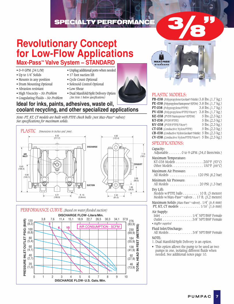
PLASTIC MODELS:PB-038 (Polypropylene/Geolast®/Nitrile) 3.8 lbs.(1,7 kg.)PE-038 (Polypropylene/Santoprene®/EPDM) 3.8 lbs.(1,7 kg.)PT-038 (Polypropylene/PTFE) 3.8 lbs.(1,7 kg.)PV-038 (Polypropylene/PTFE/Viton®) 3.8 lbs.(1,7 kg.)KE-038 (PVDF/Santoprene®/EPDM) 5 lbs.(2,3 kg.)KT-038 (PVDF/PTFE) 5 lbs.(2,3 kg.)KV-038 (PVDF/PTFE/Viton®) 5 lbs.(2,3 kg.)CT-038 (Conductive Nylon/PTFE) 5 lbs.(2,3 kg.)CB-038 (Conductive Nylon/Geolast®/Nitrile) 5 lbs.(2,3 kg.)CV-038 (Conductive Nylon/PTFE/Viton®) 5 lbs.(2,3 kg.)
SPECIFICATIONS:Capacity:Adjustable . . . . . . . 0 to 9 GPM (34,0 liters/min.)
Maximum Temperature:KT-038 Models . . . . . . . . . . . . . . . 200°F (93°C)Other Models . . . . . . . . . . . . . . . . . 150°F (66°C)
Maximum Air Pressure:All Models . . . . . . . . . . . . . . . 120 PSI (8,2 bar)
Minimum Air Pressure:All Models . . . . . . . . . . . . . . . . 20 PSI (1,3 bar)
Dry Lift:Models w/PTFE balls . . . . . . . . . 10 ft. (3 meters)Models w/Max-Pass™ valves . . 17 ft. (5,2 meters)
Maximum Solids (Max-Pass™ valves) . 1/4˝ (6,4 mm)PT, KT, CT models . . . . . . . . . . . 1/16˝ (1,6 mm)Air Supply:Inlet . . . . . . . . . . . . . . . . . 1/4˝ NPT/BSP FemaleOutlet . . . . . . . . . . . . . . . . 3/8˝ NPT/BSP Female
• Muffler supplied
Fluid Inlet/Discharge:All Models . . . . . . . . . . . . . 3/8˝ NPT/BSP Female
NOTE:1. Dual Manifold/Split Delivery is an option.• This option allows the pump to be used as two
pumps in one, isolating different fluids whenneeded. See additional notes page 10.
Revolutionary Concept for Low-Flow ApplicationsMax-Pass™ Valve System – STANDARD• 0–9 GPM (34 L/M)• Up to 1/4˝ Solids• Mounts in any position• Drum Mounting Optional• Abrasion resistant• High Viscocity – No Problem• Coagulating Fluids – No Problem
• Unplug additional ports when needed• 17 foot suction lift• Cycle Count Optional• Solenoid Control Optional• Low Shear• Dual Manifold/Split Delivery Option
(See Note 1 below specifications)
Ideal for inks, paints, adhesives, waste oil,coolant recycling, and other specialized applicationsNote: PT, KT, CT models are built with PTFE check balls (not Max-Pass™ valves) See specifications for maximum solids.
3/8”
8 P U M P A C
PERFORMANCE PLUS
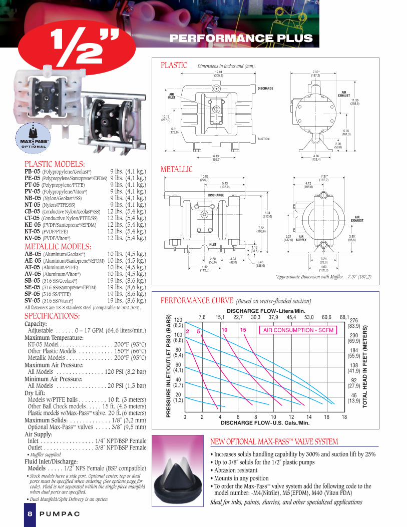
PLASTIC MODELS:PB-05 (Polypropylene/Geolast®) 9 lbs. (4,1 kg.)PE-05 (Polypropylene/Santoprene®/EPDM) 9 lbs. (4,1 kg.)PT-05 (Polypropylene/PTFE) 9 lbs. (4,1 kg.)PV-05 (Polypropylene/Viton®) 9 lbs. (4,1 kg.)NB-05 (Nylon/Geolast®/SS) 9 lbs. (4,1 kg.)NT-05 (Nylon/PTFE/SS) 9 lbs. (4,1 kg.)CB-05 (Conductive Nylon/Geolast®/SS) 12 lbs. (5,4 kg.)CT-05 (Conductive Nylon/PTFE/SS) 12 lbs. (5,4 kg.)KE-05 (PVDF/Santoprene®/EPDM) 12 lbs. (5,4 kg.)KT-05 (PVDF/PTFE) 12 lbs. (5,4 kg.)KV-05 (PVDF/Viton®) 12 lbs. (5,4 kg.)METALLIC MODELS:AB-05 (Aluminum/Geolast®) 10 lbs. (4,5 kg.)AE-05 (Aluminum/Santoprene®/EPDM) 10 lbs. (4,5 kg.)AT-05 (Aluminum/PTFE) 10 lbs. (4,5 kg.)AV-05 (Aluminum/Viton®) 10 lbs. (4,5 kg.)SB-05 (316 SS/Geolast®) 19 lbs. (8,6 kg.)SE-05 (316 SS/Santoprene®/EPDM) 19 lbs. (8,6 kg.)SP-05 (316 SS/PTFE) 19 lbs. (8,6 kg.)SV-05 (316 SS/Viton®) 19 lbs. (8,6 kg.)All fasteners are 18-8 stainless steel (comparable to 302-304).
SPECIFICATIONS:Capacity:Adjustable . . . . . . 0 – 17 GPM (64,6 liters/min.)
Maximum Temperature:KT-05 Model . . . . . . . . . . . . . . . . . 200°F (93°C)Other Plastic Models . . . . . . . . . . . 150°F (66°C)Metallic Models . . . . . . . . . . . . . . . 200°F (93°C)
Maximum Air Pressure:All Models . . . . . . . . . . . . . . . 120 PSI (8,2 bar)
Minimum Air Pressure:All Models . . . . . . . . . . . . . . . . 20 PSI (1,3 bar)
Dry Lift:Models w/PTFE balls . . . . . . . . . 10 ft. (3 meters)Other Ball Check models. . . . . 15 ft. (4,5 meters)Plastic models w/Max-Pass™ valve. 20 ft.(6 meters)
Maximum Solids: . . . . . . . . . . . . . 1/8˝ (3,2 mm)Optional Max-Pass™ valves . . . . . 3/8˝ (9,5 mm)
Air Supply:Inlet . . . . . . . . . . . . . . . . . 1/4˝ NPT/BSP FemaleOutlet . . . . . . . . . . . . . . . . 3/8˝ NPT/BSP Female• Muffler supplied
Fluid Inlet/Discharge:Models . . . . . 1/2˝ NPS Female (BSP compatible)• Stock models have a side port. Optional center, top or dual
ports must be specified when ordering (See options page forcode). Fluid is not separated within the single piece manifoldwhen dual ports are specified.
• Dual Manifold/Split Delivery is an option.
0 2 4 6 8 10 12 14 16 18
DISCHARGE FLOW-Liters/Min.
120(8,2)
100(6,8)
80(5,4)
60(4,1)
40(2,7)
20(1,3)
PR
ES
SU
RE
INL
ET
/OU
TL
ET
PS
IG (
BA
RS
)
DISCHARGE FLOW-U.S. Gals./Min.
7,6 15,1 22,7 30,3 37,9 45,4 53,0 60,6 68,1
AIR CONSUMPTION - SCFM5
TOTA
L H
EA
D IN
FE
ET
(M
ET
ER
S)
276(83,9)
230(69,9)
184(55,9)
138(41,9)
92(27,9)
46(13,9)
15102
PERFORMANCE CURVE (Based on water-flooded suction)
PLASTIC Dimensions in inches and (mm).12.04
(305,8)
6.81(173,0)
10.12(257,0)
6.13(155,7)
AIRINLET
DISCHARGE
SUCTION2.00
(50,8)
11.36(288,5)
6.35(161.3)
4.86(123,4)
AIREXHAUST
7.37*(187,2)
NEW OPTIONAL MAX-PASS™ VALVE SYSTEM• Increases solids handling capability by 300% and suction lift by 25%• Up to 3/8˝ solids for the 1/2˝ plastic pumps• Abrasion resistant• Mounts in any position• To order the Max-Pass™ valve system add the following code to the
model number: -M4(Nitrile), M5(EPDM), M40 (Viton FDA)Ideal for inks, paints, slurries, and other specialized applications
1/2”
METALLIC10.86
(276,0)
DISCHARGE
5.43(138,0)
INLET
5.43(138,0)
1.13(28,6)
4.40(112,0)
3.23(82,0)
2.20(56,0)
7.82(198,6)
8.34(212,0) AIR
EXHAUST
4.12(105,0)
7.37*(187,2)
4.00(102,0)
3.24(82,0)
AIRSUPPLY
5.21(132,0)
3.80(96,5)
*Approximate Dimension with Muffler–– 7.37 (187,2)

PERFORMANCE PLUS
9P U M P A C
0
DISCHARGE FLOW-Liters/Min.23
20(1,3)
PR
ES
SU
RE
INL
ET
/OU
TL
ET
PS
IG (
BA
R)
10
DISCHARGE FLOW-U.S. Gals./Min.
20
40
30
AIR CONSUMPTION - SCFM
40(2,7)
60(4,1)
80(5,4)
100(6,8)
120(8,2)
0 6 12 18 24 30 36 42 48
45 68 91 114 136 159
TOTA
L H
EA
D IN
FE
ET
(M
ET
ER
S)
230(69,9)
184(55,9)
138(41,9)
92(27,9)
46(13,9)
PERFORMANCE CURVE (Based on water-flooded suction)
PLASTIC Dimensions in inches and (mm).17.26
(438,4)
2.60(66,0)
6.81(173,0)
14.10(358,1)
16.32(414,5)
8.54(216,9)
11.95(303,5)
6.25(158,8)
AIRINLET
AIREXHAUST
DISCHARGE
SUCTION
9.46(240,3)
8.88*(225,5)
PLASTIC MODELS:PB-10 (Polypropylene/Geolast®) 20 lbs. (9,1 kg.)PE-10 (Polypropylene/Santoprene®/EPDM) 20 lbs. (9,1 kg.)PT-10 (Polypropylene/PTFE) 20 lbs. (9,1 kg.)PV-10 (Polypropylene/Viton®) 20 lbs. (9,1 kg.)KT-10 (PVDF/PTFE) 30 lbs. (13,7 kg.)KE-10 (PVDF/Santoprene®/EPDM) 30 lbs. (13,7 kg.)KV-10 (PVDF/Viton®) 30 lbs. (13,7 kg.)
METALLIC MODELS:AB-10 (Aluminum/Geolast®) 23 lbs. (10,5 kg.)AE-10 (Aluminum/Santoprene®/EPDM)23 lbs. (10,5 kg.)AT-10 (Aluminum/PTFE) 23 lbs. (10,5 kg.)AV-10 (Aluminum/Viton®) 23 lbs. (10,5 kg.)SB-10 (316 SS/Geolast®) 45 lbs. (20,4 kg.)SE-10 (316 SS/Santoprene®/EPDM) 45 lbs. (20,4 kg.)SP-10 (316 SS/PTFE) 45 lbs. (20,4 kg.)SV-10 (316 SS/Viton®) 45 lbs. (20,4 kg.)All fasteners are 18-8 stainless steel (comparable to 302-304).
SPECIFICATIONS:Capacity:Adjustable . . . . . 0 – 41 GPM (155,8 liters/min.)
Maximum Temperature:KT-10 Model . . . . . . . . . . . . . . . . . 200°F (93°C)Other Plastic Models . . . . . . . . . . . 150°F (66°C)Metallic Models . . . . . . . . . . . . . . . 200°F (93°C)
Maximum Air Pressure:All Models . . . . . . . . . . . . . . . 120 PSI (8,2 bar)
Minimum Air Pressure:All Models . . . . . . . . . . . . . . . . 20 PSI (1,3 bar)
Dry Lift:Models w/PTFE balls . . . . . . . . . 10 ft. (3 meters)Other Ball Check models . . . . . 15 ft. (4,5 meters)Plastic models w/Max-Pass™ valve. 18 ft.(5,5 meters)
Maximum Solids: . . . . . . . . . . . . . 1/4˝ (6,4 mm)Max-Pass™ valves (plastic pumps) . . . 3/4˝ (19 mm)Max-Pass™ valves (metal pumps) . . 1/2˝ (12,7 mm)
Air Supply:Inlet . . . . . . . . . . . . . . . . . 1/4˝ NPT/BSP FemaleOutlet . . . . . . . . . . . . . . . . 3/8˝ NPT/BSP Female• Muffler supplied
Fluid Inlet/Discharge:Plastic Models . . . 1˝ Flange ANSI/DIN compatibleMetallic Models . . . . . . . . . . . . . . . . . . . . 1˝ NPT• For optional BSP threads add - P15 to Model No.
• For Plastic Pumps Only: Stock models have a flanged side port.Optional threaded center ports must be specified when ordering(See options page for code).
2.09(53,1)
1.31(33,3)
1.44(36,6)
12.00(304,8)
DISCHARGE
6.00(152,4)
SUCTION
0.34(8,64)
3.38(85,9)
6.76(171,7)
7.80(198,1)
AIRSUPPLY
4.75(120,7)
4.12(104,6)5.00
(127,0)
11.87(301,5)
12.65(321,3)
6.87(174,5)
AIREXHAUST
8.88*(225,5)
7.31(185,7)
METALLIC Dimensions in inches and (mm).
*Approximate Dimension with Muffler–– 10.25 (260,4)
NEW OPTIONAL MAX-PASS™ VALVE SYSTEM• Increases solids handling capability by 300% and suction lift by 25%• Up to 3/4˝ solids for the 1˝ plastic pumps• Abrasion resistant• Mounts in any position• To order the Max-Pass™ valve system add the following code to the
model number: -M4(Nitrile), M5(EPDM), M40 (Viton FDA)Ideal for inks, paints, slurries, and other specialized applications
1”

Dual Manifold/Split Delivery1. The pump can be used as two pumps in one, isolating
two different fluids or recycling on one side and using theopposite side for delivery.
2. A dual manifold used only on the suction side of thepump can be used to mix two different fluid that must bekept separate prior to transfer such as a two part epoxy.
3. A dual manifold used only on the discharge side of thepump will split the delivery.
0 10 25 405
DISCHARGE FLOW-Liters/Min.19 38 152
20(1,3)
40(2,7)
60(4,1)
80(5,4)
100(6,8)
230(69,9)
184(55,9)
138(41,9)
92(27,9)
46(13,9)
TOTA
L H
EA
D IN
FE
ET
(M
ET
ER
S)
PR
ES
SU
RE
INL
ET
/OU
TL
ET
PS
IG (
BA
R)
10
DISCHARGE FLOW-U.S. Gals./Min.
13357 76 11495
15 20 3530
20
40
30 AIR CONSUMPTION - SCFM
1⁄ 2˝ MODELS:NC-5 (Polypropylene/Geolast®) 8 lbs. (3,6 kg.)BK-5 (Polypropylene/PTFE) 8 lbs. (3,6 kg.)BK-5E (Polypropylene/Santoprene®) 8 lbs. (3,6 kg.)KN-5 (PVDF/PTFE) 11 lbs. (4,9 kg.)KN-5E (PVDF/Santoprene®) 11 lbs. (4,9 kg.)
1˝ MODELS:NC-10 (Polypropylene/Geolast®) 19 lbs. (8,6 kg.)BK-10 (Polypropylene/PTFE) 19 lbs. (8,6 kg.)BK-10E (Polypropylene/Santoprene®) 19 lbs. (8,6 kg.)KN-10 (PVDF/PTFE) 22 lbs. (9,9 kg.)KN-10E (PVDF/Santoprene®) 22 lbs. (9,9 kg.)See page 4 for fastener and valve seat material.
SPECIFICATIONS:Maximum Temperature:KN Models . . . . . . . . . . . . . . . . . . 200°F (93°C)Other Models. . . . . . . . . . . . . . . . . 150°F (66°C)
Maximum Air Pressure: . . . . . . 100 PSI (6,8 bar)Minimum Air Pressure: . . . . . . . 20 PSI (1,3 bar)Dry Lift:Models w/PTFE balls . . . . . . . . . 10 ft. (3 meters)Other Models . . . . . . . . . . . . . 15 ft. (4,5 meters)
SPECIFICATIONS (1⁄ 2˝ MODELS):Capacity:Adjustable . . . . . . 0 to 14 GPM (53,2 liters/min.)
Maximum Solids: . . . . . . . . . . . . . 1/8˝ (3,2 mm)Air Supply:Inlet . . . . . . . . . . . . . . . . . . . . . 1/4˝ NPT Female• Air flow control valve supplied,1/4˝ NPT or 1/2˝ BSP Female
Outlet. . . . . . . . . . . . . . . . . . . . 3/8˝ NPT Female• Muffler supplied
Fluid Inlet/Discharge:All Models . . . . . . . . . . . . . . . . 1/2˝ NPS Female(BSP or NPT Compatible)• For optional dual manifold inlet/outlet, add –P25 to Model No.
SPECIFICATIONS (1˝ MODELS):Capacity:Adjustable . . . . . . 0 to 40 GPM (152 liters/min.)
Maximum Solids: . . . . . . . . . . . . . 1/4˝ (6,4 mm)Air Supply:Inlet . . . . . . . . . . . . . . . . . . . . . 1/4˝ NPT FemaleOutlet. . . . . . . . . . . . . . . . . . . . 3/8˝ NPT Female• Muffler supplied
Fluid Inlet/Discharge: . . . . . . . . . . . . . . . . 1˝ NPT• For optional BSP threads, add -P15 to Model No.
PERFORMANCE CURVE (1˝ MODELS)
0 6 102
DISCHARGE FLOW-Liters/Min.7,6 15,2 60,8
20(1,3)
40(2,7)
60(4,1)
80(5,4)
100(6,8)
230(69,9)
184(55,9)
138(41,9)
92(27,9)
46(13,9)
TOTA
L H
EA
D IN
FE
ET
(M
ET
ER
S)
PR
ES
SU
RE
INL
ET
/OU
TL
ET
PS
IG (
BA
R)
15
52 10
DISCHARGE FLOW-U.S. Gals./Min.
53,222,8 30,4 45,638,0
4 8 12 14 16
AIR CONSUMPTION - SCFM
PERFORMANCE CURVE (1⁄ 2˝ MODELS)
AIR INLET
DISCHARGE
SUCTION
A
B
C
D
E
F
G
HDia.
4 Holes
AIREXHAUST
K
L
J*
M
PLASTIC Dimensions in inches and (mm). Ports shown facing front for dimensional purposes.
10 P U M P A C
*Approximate Dimension with Muffler–– P
•1” CLASSIC PERFORMANCE1⁄2”
MODEL DIMENSIONS Inches / (mm)SIZE A B C D E F G H J K L M P
1⁄2˝ 9.76 10.75 9.38 6.19 1.38 5.70 6.70 0.31 7.50 3.26 4.00 5.12 8.00Models (248,0) (273,0) (238,0) (157,2) (35,0) (145,0) (170,0) (8,0) (190,5) (83,0) (102,0) (130,0) (203.2)
1˝ 12.00 15.50 13.50 8.30 2.00 5.74 7.62 0.44 9.90 5.12 6.00 8.30 11.57Models (305,0) (394,0) (343,0) (211,0) (51,0) (146,0) (194,0) (11,2) (252,0) (130,0) (152,4) (211,0) (293,9)
• Add -P25 after the modelnumber to have the pumpconfigured at the factorywith dual manifolds.
• Fluid must be transferredthrough both sides of the pump.

11P U M P A C
PERFORMANCE PLUS
0 20 40 60 80 100 120 140
DISCHARGE FLOW-Liters/Min.
120(8,2)
100(6,8)
80(5,4)
60(4,1)
40(2,7)
20(1,3)
TOTA
L H
EA
D IN
FE
ET
(M
ET
ER
S)
PR
ES
SU
RE
INL
ET
/OU
TL
ET
PS
IG (
BA
RS
)
DISCHARGE FLOW-U.S. Gals./Min.
AIR CONSUMPTION - SCFM
76 152 228 304 380 456 532276
(83,9)
230(69,9)
184(55,9)
138(41,9)
92(27,9)
46(13,9)
3550 70
PLASTIC MODELS:PB-15 (Polypropylene/Geolast®) 46 lbs. (20,8 kg.)PT-15 (Polypropylene/PTFE) 46 lbs. (20,8 kg.)PE-15 (Polypropylene/Santoprene®) 46 lbs. (20,8 kg.)KT-15 (PVDF/PTFE) 65 lbs. (29,4 kg.)KE-15 (PVDF/Santoprene®) 65 lbs. (29,4 kg.)
METALLIC MODELS:AB-15 (Aluminum/Geolast®) 60 lbs. (27,2 kg.)AE-15 (Aluminum/Santoprene®) 60 lbs. (27,2 kg.)AT-15 (Aluminum/PTFE) 60 lbs. (27,2 kg.)SP-15 (316 Stainless Steel/PTFE) 133 lbs. (60 kg.)SE-15 (316 Stainless/Santoprene®) 133 lbs. (60 kg.)SB-15 (316 Stainless/Geolast®) 133 lbs. (60 kg.)See page 4 for fastener and valve seat material.
SPECIFICATIONS:Capacity:Adjustable . . . . . 0 to 130 GPM (492 liters/min.)
Maximum Temperature:KT-15 Model . . . . . . . . . . . . . . . . . 200°F (93°C)Other Plastic Models . . . . . . . . . . . 150°F (66°C)Metallic Models . . . . . . . . . . . . . . . 200°F (93°C)
Maximum Air Pressure:All Models . . . . . . . . . . . . . . . 120 PSI (8,2 bar)
Minimum Air Pressure:All Models . . . . . . . . . . . . . . . . 20 PSI (1,3 bar)
Dry Lift:Models w/PTFE balls . . . . . . . . . 10 ft. (3 meters)Other Models . . . . . . . . . . . . . 15 ft. (4,5 meters)
Maximum Solids: . . . . . . . . . . . . . 1/4˝ (6,4 mm)Air Supply:Inlet . . . . . . . . . . . . . . . . . 3/4˝ NPT/BSP FemaleOutlet . . . . . . . . . . . . . . . . 3/4˝ NPT/BSP Female• Muffler supplied
Fluid Inlet/Discharge: . . 1-1/2˝ Flange (38,1 mm)• Flanges are ANSI and DIN compatible
• Threaded companion flanges available
PERFORMANCE CURVE
DISCHARGE
SUCTION
DIA – 4 SLOTS
AIR INLET
0.56(14,2)
19.50(495,0)
9.31(236,4)11.15
(283,0)
3.19(81,0)
12.46(316,5)
20.74(526,8)
23.24(590,3)
AIR EXHAUST
11.88(301,8)
12.75(324,0)
5.00(127,0)
6.00(152,4)
METALLIC
3.12(79,2)
SUCTION
AIRINLET
20.58(522,7)
9.34(237,2)
11.18(283,9)
0.56(14,2) DIA – 4 SLOTS
12.30(312,4)
18.90(480,0)
21.77(552,9)
DISCHARGE
7.00(177,8)
8.00(203,2)
AIR EXHAUST
12.20(309,9)
11.37(288,8)
PLASTIC Dimensions in inches and (mm).
Flanges are ANSI/DIN Compatible
11/2”NEWNEW

0 20 40 60 80 100 120 140 160 180
DISCHARGE FLOW-Liters/Min.
120(8,2)
100(6,8)
80(5,4)
60(4,1)
40(2,7)
20(1,3)
TOTA
L H
EA
D IN
FE
ET
(M
ET
ER
S)
PR
ES
SU
RE
INL
ET
/OU
TL
ET
PS
IG (
BA
RS
)
DISCHARGE FLOW-U.S. Gals./Min.
AIR CONSUMPTION - SCFM
76 152 228 304 380 456 532 608 684276
(83,9)
230(69,9)
184(55,9)
138(41,9)
92(27,9)
46(13,9)
3050 70
PLASTIC MODELS:PB-20 (Polypropylene/Geolast®) 48 lbs. (21,7 kg.)PT-20 (Polypropylene/PTFE) 48 lbs. (21,7 kg.)PE-20 (Polypropylene/Santoprene®) 48 lbs. (21,7 kg.)KT-20 (PVDF/PTFE) 69 lbs. (31,3 kg.)KE-20 (PVDF/Santoprene®) 69 lbs. (31,3 kg.)
METALLIC MODELS:AB-20 (Aluminum/Geolast®) 61 lbs. (27,7 kg.)AE-20 (Aluminum/Santoprene®) 61 lbs. (27,7 kg.)AT-20 (Aluminum/PTFE) 61 lbs. (27,7 kg.)SP-20 (316 Stainless Steel/PTFE) 133 lbs. (60 kg.)SB-20 (316 Stainless/Geolast®) 133 lbs. (60 kg.)SE-20 (316 Stainless/Santoprene®) 133 lbs. (60 kg.)See page 4 for fastener and valve seat material.
SPECIFICATIONS:Capacity:Adjustable 0 to 180 GPM (681 liters/min.)
Maximum Temperature:KN-20 Model 200°F (93°C)Other Plastic Models 150°F (66°C)Metallic Models 200°F (93°C)
Maximum Air Pressure:All Models 120 PSI (8,2 bar)
Minimum Air Pressure:All Models 20 PSI (1,3 bar)
Dry Lift:Models w/PTFE balls 10 ft. (3 meters)Other Models 15 ft. (4,5 meters)
Maximum Solids: 1/4˝ (6,4 mm)Air Supply:Inlet 3/4˝ NPT/BSP FemaleOutlet 3/4˝ NPT/BSP Female• Muffler supplied
Fluid Inlet/Discharge: 2˝ (51mm)Flange1. Plastic Pumps – ANSI and DIN flanges• Threaded companion flanges available
2. Metal Pumps – 2˝ NPT threads standard• 2˝(51mm) BSP threads optional – Add –P15 to Model No.
3. Stainless Pump Option• Tri-Clamp Fittings – Add –X44 to Model No.
PERFORMANCE CURVE
3.50(89,0)
SUCTION
AIRINLET
20.58(522,7)
12.00(304,8)
14.00(355,6)
0.56(14,2) DIA – 4 SLOTS
14.08(357,6)
23.65(600,7)
26.65(676,9)
DISCHARGE
5.00(127,0)
6.00(152,4)
AIR EXHAUST
12.20(309,9)
13.15(334,1)
PLASTIC
A
DISCHARGE
E
D
C
B
SUCTION
FG
AIRINLET
DIA – 4 SLOTS0.56(14,2)
KL
M
J
AIR EXHAUST
METALLIC
12 P U M P A C
Dimensions in inches and (mm).
PERFORMANCE PLUS
MODEL DIMENSIONS Inches / (mm)SIZE (Inlet/Outlet) A B C D E F G J K L M
2˝ Aluminum 19.50 26.26 25.04 13.86 2.25 10.06 12.00 12.20 5.00 6.00 12.90NPT & BSP (495,0) (667,0) (636,0) (352,0) (57,1) (255,5) (304,8) (309,9) (127,0) (152,4) (327,6)
2˝ Stainless Steel 19.50 24.62 23.00 15.05 3.50 12.00 13.85 12.20 5.00 6.00 14.10NPT & BSP (495,0) (625,3) (584,2) (382,3) (89,0) (304,8) (351,5) (309,9) (127,0) (152,4) (358,1)
Metal Flange Optional 19.50 24.62 21.62 13.25 3.50 12.00 13.85 11.88 5.00 6.00 12.752˝ Flange (495,0) (625,3) (549,2) (336,6) (89,0) (304,8) (351,5) (301,8) (127,0) (152,4) (324,0)
2”NEWNEW

PERFORMANCE PLUS
13P U M P A C
METALLIC MODELS:AL-30 (Aluminum/Urethane/Geolast®) 130 lbs. (59 kg.)AL-30E (Aluminum/Santoprene®/EPDM) 130 lbs. (59 kg.)AL-30T (Aluminum/PTFE) 130 lbs. (59 kg.)AL-30V (Aluminum/Viton®) 130 lbs. (59 kg.)
SPECIFICATIONS:Capacity:Adjustable . . . . . 0 to 255 GPM (965 liters/min.)
Maximum Temperature:All Models. . . . . . . . . . . . . . . . . . . 200°F (93°C)
Maximum Air Pressure:All Models . . . . . . . . . . . . . . . 120 PSI (8,2 bar)
Minimum Air Pressure:All Models . . . . . . . . . . . . . . . . 20 PSI (1,3 bar)
Dry Lift:Models w/PTFE balls . . . . . . . . . 10 ft. (3 meters)Other Models . . . . . . . . . . . . . 15 ft. (4,5 meters)
Maximum Solids: . . . . . . . . . . . 7/16˝ (11,1 mm)Air Supply:Inlet . . . . . . . . . . . . . . . . . 3/4˝ NPT/BSP FemaleOutlet . . . . . . . . . . . . . . . . 3/4˝ NPT/BSP Female• Muffler supplied
Fluid Inlet/Discharge:Metallic Models. . . . . . . . . . . . . . 3 ˝ NPT Female• For optional BSP threads add –P15 to Model No.
0 30 60 90 120 150 180 210 240 270
DISCHARGE FLOW-Liters/Min.
120(8,2)
100(6,8)
80(5,4)
60(4,1)
40(2,7)
20(1,3)
TOTA
L H
EA
D IN
FE
ET
(M
ET
ER
S)
PR
ES
SU
RE
INL
ET
/OU
TL
ET
PS
IG (
BA
RS
)
25
DISCHARGE FLOW-U.S. Gals./Min.
AIR CONSUMPTION - SCFM
114 228 342 456 570 684 798 912 1026276
(83,9)
230(69,9)
184(55,9)
138(41,9)
92(27,9)
46(13,9)
50
75 100125
150
PERFORMANCE CURVE (Based on water-flooded suction)
METALLIC Dimensions in inches and (mm). Ports shown facing front for dimensional purposes.
AIREXHAUST
AIRSUPPLY3/4” NPT
2.40(61)
16.06(408)
29.97(761)
24.50(622)
10.14(258) 11.18
(284)
10.15(258)
16.76(426)
32.25(819)
3” NPT(BSP threadsavailable onrequest)
DISCHARGE
SUCTION
5.07(129)
3”
Optional3” Pump Accessories
• Carry HandlesPart No. 52000(Kit contains 2 handles)
• Strainer BasePart No. 53000
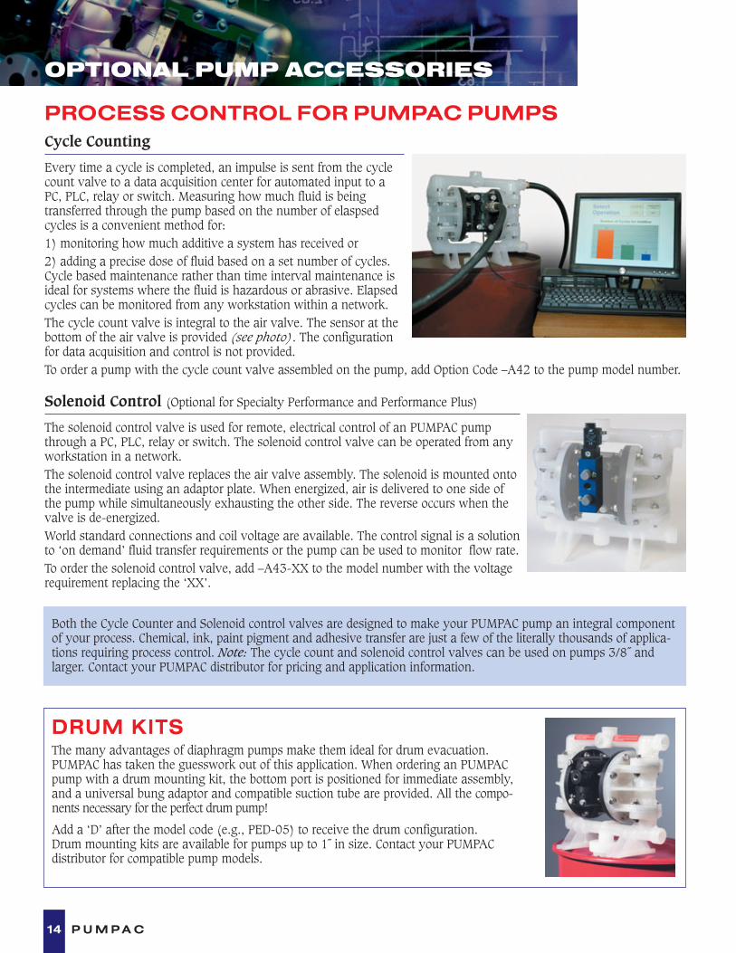
Cycle Counting
Every time a cycle is completed, an impulse is sent from the cyclecount valve to a data acquisition center for automated input to aPC, PLC, relay or switch. Measuring how much fluid is being transferred through the pump based on the number of elaspsedcycles is a convenient method for:1) monitoring how much additive a system has received or 2) adding a precise dose of fluid based on a set number of cycles.Cycle based maintenance rather than time interval maintenance isideal for systems where the fluid is hazardous or abrasive. Elapsedcycles can be monitored from any workstation within a network.The cycle count valve is integral to the air valve. The sensor at thebottom of the air valve is provided (see photo). The configurationfor data acquisition and control is not provided.To order a pump with the cycle count valve assembled on the pump, add Option Code –A42 to the pump model number.
14 P U M P A C
OPTIONAL PUMP ACCESSORIES
PROCESS CONTROL FOR PUMPAC PUMPS
Solenoid Control (Optional for Specialty Performance and Performance Plus)
The solenoid control valve is used for remote, electrical control of an PUMPAC pumpthrough a PC, PLC, relay or switch. The solenoid control valve can be operated from anyworkstation in a network.The solenoid control valve replaces the air valve assembly. The solenoid is mounted ontothe intermediate using an adaptor plate. When energized, air is delivered to one side ofthe pump while simultaneously exhausting the other side. The reverse occurs when thevalve is de-energized. World standard connections and coil voltage are available. The control signal is a solutionto ‘on demand’ fluid transfer requirements or the pump can be used to monitor flow rate.To order the solenoid control valve, add –A43-XX to the model number with the voltagerequirement replacing the ‘XX’.
DRUM KITSThe many advantages of diaphragm pumps make them ideal for drum evacuation. PUMPAC has taken the guesswork out of this application. When ordering an PUMPACpump with a drum mounting kit, the bottom port is positioned for immediate assembly,and a universal bung adaptor and compatible suction tube are provided. All the compo-nents necessary for the perfect drum pump!
Add a ‘D’ after the model code (e.g., PED-05) to receive the drum configuration. Drum mounting kits are available for pumps up to 1˝ in size. Contact your PUMPAC distributor for compatible pump models.
Both the Cycle Counter and Solenoid control valves are designed to make your PUMPAC pump an integral componentof your process. Chemical, ink, paint pigment and adhesive transfer are just a few of the literally thousands of applica-tions requiring process control. Note: The cycle count and solenoid control valves can be used on pumps 3/8˝ and larger. Contact your PUMPAC distributor for pricing and application information.

15P U M P A C
BUILT FOR THE REAL WORLD
PUMPAC pumps are providing trouble-free service on all types of industrial applications worldwide. Whatever the application, industry or operating environment, your PUMPAC distributor is ready to
help you select the right pump for your application and work with you to ensure trouble-free operation.
E A C H P U M P A C P U M P I S B A C K E D B Y A 5 - Y E A R W A R R A N T Y A N D T E S T E D B E F O R E S H I P M E N T .
Your PUMPAC Double Diaphragm Pump is warranted to the original user against defects in workmanship or materials under normal use (rentaluse excluded) for five years after purchase date. Any pump which is determined to be defective in material and workmanship and returned to PUMPAC Pump Co., shipping costs prepaid, will be repaired or replaced at PUMPAC’s option.
This warranty does not cover failure of parts or components due to normal wear or damage or failure which in thejudgment of PUMPAC arises from misuse, abrasion, corrosion, negligence, accidental damage, faulty installation ortampering. If PUMPAC inspection discloses no defect in material or workmanship, repair or replacement and return will be made at customary charges.
PUMPAC has made a diligent effort to accurately illustrate and describe its product in this literature. However, such illustrations and descriptions are not a warranty. THE ABOVE EXPRESS WARRANTY IS IN LIEU OF AND EXCLUDES ALL OTHER WARRANTIES, EXPRESS OR IMPLIED, INCLUDING, WITHOUT LIMITATION, MERCHANTABILITY OR FITNESS FOR A PARTICULAR PURPOSE.
Purchaser shall give written notice of any claim to PUMPAC within ten days after discovery of any alleged defect. PUMPAC SHALL NOT BELIABLE FOR CONSEQUENTIAL DAMAGES, LOSSES, DELAYS, LABOR COSTS OR ANY OTHER EXPENSE DIRECTLY OR INDIRECTLY ARISINGFROM USE OF THE PUMP, ITS LIABILITY BEING EXPRESSLY LIMITED TO THE REPLACEMENT OR REPAIR OF ANY DEFECTIVE PUMP ORAN ALLOWANCE OF CREDIT THEREFORE. THE REMEDY AND RECOVERY OF THE PURCHASER ON ANY CLAIM AGAINST PUMPAC,WHETHER BASED ON CONTRACT, THIS WARRANTY OR ANY ALLEGED NEGLIGENCE SHALL BE AS STATED AND LIMITED HEREIN ANDSHALL BE EXCLUSIVE.
5YEAR
WARRANTY

Made in the USA
PumpacWest Garfield, PO Box 622, Aurora, Ohio 44202 USA
Phone: 440.708.0677 Fax: 440.543.2832Business Site: www.pumpac.com E-Mail: [email protected]