air cooled condensing units - airvie · engineering data manual chiller 43.2 to 84.5 kw. 2...
TRANSCRIPT

AQC 40 to 75
Air Cooled Condensing UnitsEngineering Data Manual
Chiller
43.2 to 84.5 kW

2
Outstanding Strength Points
R410A Refrigerant.
New simpler refrigerant circuit layout.
Low sound level for BLN unit, very low sound level for ELN unit.
Great accessibility to internal components for service operations.
New display on external panel allows the complete control of the unit.
More assembling quality.
Construction easier.
Operating limit of the unit stored in the flash memory of the control logic.
Wide operating limits.
High temperature operating limits.
Less noisy compared to the unit with R407C.
Less number of screws and piece of sheet metal.
Component standardization (symmetric sheet metal, only 2 kinds of screws …).
New gauge kit can be fitted directly inside the units and not outside. This gauge kit is cheaper than R407C one and it is common for the whole range.
Fan speed control for low ambient operation in cooling mode down to -18 °C.
ModBus interface.
Phase sequence monitor supplied as standard.
User-friendly microprocessor control.
For safety during service operations, special valves dedicated to R410A are available on the refrigerant system. These valves, of 5/16” flare SAE type, are mounted on the liquid line inside and on the lateral panel of the unit. This facilitates the access to the high and low side of the refrigerant circuit in order to do pressure measurement.
Rubber pad supplied as standard.
New anti-vibration kit, easier to be installed (same spring for every corner).
Special Inverter Fan (SIF) version suitable for a widening of operating conditions, like ducted installation where high static pressure is needed or high ambient air temperature installation. Fan speed will be regulated by condensing pressure.
Smaller footprint. The units are 100 mm thinner in order to simplify the transport operation.
Extra low noise version now available.
Smart hook in the electrical panel that keeps in position the closing panel while the operator is working on the electrical box.
Refrigerant circuit completely enclosed in a separated box in order to reduce the noise, not only of the compressors but also of the whole circuit.
General
The new AQC air cooled condensing units have been designed and optimized to operate with R410A refrigerant fluid.
The AQC range consists of 6 sizes (40, 45, 50, 60, 65 & 75) and covers a nominal cooling capacity range from 43.2 to 84.5 kW.
All units are equipped two scroll compressors fitted in tandem for adapting to partial system loads.
The general operation status of the machine is continuously under the control of a microprocessor based controller.
A fan speed controller can be supplied loose as field-installed accessory to authorize the unit to operate in cooling mode at low ambient temperature.
The AQC units can be supplied in 3 versions :
Base Low Noise (BLN) : This version is equipped with delta connected fan motors.
Extra Low Noise (ELN) : This version is equipped with star connected fan motors which allow the unit to operate with a very low rpm. Compressor sound proof jackets are also supplied as standard on this version.
Special Inverter Fan (SIF) : This version is equipped with inverter fan that allows the unit to be used as ducted or high ambient temperature unit thanks to the high static pressure and the high air flow provided by inverter fan.
Specifications
Cabinet and structure
The cabinet and structure are made of heavy gauge galvanized steel. All galvanized steel components are individually painted by a special painting process before the assembly of the unit. This painting system performs a homogeneous protection to the corrosion.
The painting is a polyester powder based type, coloured in RAL 9001.
The units are suitable for outdoor installation, directly on the building roof or at the ground level.
Compressors
Each unit is equipped with two scroll compressors fitted on a rail and assembled together to form tandem compressors. The compressors are then mounted on rubber pads in order to eliminate noise and vibration transmissions.
The compressor motors have a direct start-up. Each motor is cooled by the refrigerant gas and is equipped with an overload protection.
A soft start system can be supplied as optional, whereas a phase sequence monitor is supplied as standard.
Condenser
The condenser is a finned coil constructed with seamless copper tubes mechanically expanded into aluminium fins.
The condenser coil is composed of internally smooth tubes with louvered fins to improve the heat transfer.
The air cooled condenser is supplied with a protective grille as standard.

3
Specifications (continued)
Condenser fans and motors
Each unit has one axial fan, of fixed speed type with diameter of 800 mm. According to the version, the fan is cabled in order to have high speed (700 to 900 rpm) for BLN version and low speed (530 to 680 rpm) to reduce the sound level for ELN version.
The fan motor has IP54 grade and is equipped with a thermal overload protection.
A pressure actuated fan speed controller can be supplied as field-installed accessory or factory-fitted option. It allows the unit to operate in cooling mode at ambient temperature down to -18 °C because it regulates the fan speed in order to maintain constant the condensing temperature.
On the SIF version, the fan is controlled by a 0-10 V DC signal that regulates the speed from 0 to 1110 rpm. This special fan allows the unit to be used in two applications :
- High ambient temperature : The fan provides high air flow at maximum speed in order to keep a low condensing temperature while operating at high air temperature.
- Ducted installation : The fan provides high static pressure in order to allow the unit to be ducted.
The SIF fan can also be evolved in order to avoid the use of a fan speed controller.
All types of fans are fitted with a protective grille on top.
Refrigerant circuit
All units have one refrigerant circuit consisting of scroll tandem compressors, condenser coil, as well as safety and control devices, such as : high pressure switch, high/low pressure transducers and PED safety valve.
The refrigerant circuit is also fitted with suction and liquide line shut-off valves to allow the connection of the unit to the external evaporator.
A gauge kit can be supplied as a common accessory for all sizes to be installed inside the unit in order to read the high and low pressure values.
All refrigerant components are shown in the functional diagrams illustrated in the next pages, section "Refrigerant flow diagrams".
Control panel
The units are fitted with an external control panel that displays the operating parameters and alarms. This control panel is accessible from outside without removing any parts because it is placed on an external panel. A Plexiglas cover protects the control from external agent.
The AQC units are equipped with the "CHILLER CONTROL" system that has the main features as stated below :
microprocessor control,
user-friendly keyboard,
access code to enter the Manufacturer's Level,
access code to enter the Assistance Level,
Alarm and LED,
backlighted LCD,
pump-down logic (start-stop),
rotation of the compressor operation,
oil return function,
night mode (or Low Noise) control,
counting of the pump/compressor's hours of operation,
display of discharge and suction pressure values,
display of temperature sensor,
history of stored alarms (option),
programming of different setpoints with 4 ranges of time/setpoint.
The following accessories can be also connected :
➜ serial communication RS485 card; to connect the "Chiller control" to a BMS network,
➜ remote display terminal,
➜ wire remote control.
The control system consists of a microprocessor card which is fully programmed by default for the control of a condensing unit, and a keyboard and display terminal.
The figure below shows the terminal with the front door open.
It is provided with a LCD 4 lines x 20 columns, keyboard and microprocessor-controlled LED's, so as to allow the programming of the control parameters (setpoint, differential bands, alarm thresholds) and the main operations to be carried out by the user.
Keyboard and display terminal
The terminal makes it possible to carry out the following operations :
the initial configuration of the machine,
the change of all the main operating parameters,
the display of the detected alarms,
the display of all measured quantities.
The terminal and the card are connected by a 6-way phone cable.

4
Specifications (continued)
Control and safety devices
Each unit is complete with the following safety and control devices :
Safety :
➜ Fan motor overload protection,
➜ Compressor motor overload protection,
➜ High pressure switch,
➜ High and low pressure transducers,
➜ Crankcase oil electric heater,
➜ 45 bar refrigerant safety valve,
Control :
➜ Discharge temperature sensor,
➜ Air temperature sensor,
➜ Suction and discharge pressure transducers.
Conformity with standards
All AQC units are in compliance with the following standards :
3 Machine Directive : 2006/42/EC
3 Low Voltage Directive : 2006/95/EC
3 Electromagnetic Compatibility Directive : 2004/108/EC
3 Pressure Equipment Directive : 97/23/EC
Factory-installed options
➜ Blue fin coil,
➜ Coil with "Fin Guard Silver" treatment,
➜ Coil with black epoxy treatment,
➜ Soft starter,
➜ Power supply without neutral kit,
➜ Automatic circuit breaker,
➜ Compressor overload protection,
➜ Fan speed control kit,
Field-installed accessories
➜ Antivibration kit,
➜ Fan speed control kit,
➜ Gauge kit,
➜ Remote On/Off control,
➜ ModBus protocol kit for BMS,
➜ Power factor correction capacitors,
➜ Sequencer for up to 4 unit installation,
➜ Compressor soundproof jackets (this option is standard on ELN version).
5
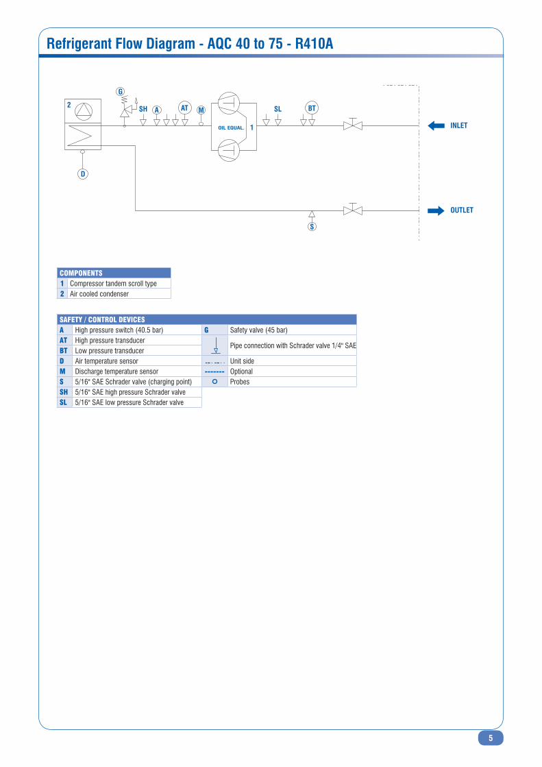
Refrigerant Flow Diagram - AQC 40 to 75 - R410A
safety / control devicesa High pressure switch (40.5 bar) G Safety valve (45 bar)at High pressure transducer
Pipe connection with Schrader valve 1/4" SAEBt Low pressure transducerd Air temperature sensor Unit sideM Discharge temperature sensor ------- Optionals 5/16" SAE Schrader valve (charging point) ProbessH 5/16" SAE high pressure Schrader valvesl 5/16" SAE low pressure Schrader valve
coMponents1 Compressor tandem scroll type2 Air cooled condenser
A
G
SH
INLET
OUTLET
SL BT
S
D
1OIL EQUAL.
2 AT M

6
Operating Limits
-25
-15 -14 -13 -12 -11 -10 -9 -8 -7 -6 -5 -4 -3 -2 -1 0 1 2 3 4 5 6 7 8 9 10 11 12 13 14 15
-20
-15
-10
-5
0
5
10
15
20
25
30
35
40
45
50
-25
-15 -14 -13 -12 -11 -10 -9 -8 -7 -6 -5 -4 -3 -2 -1 0 1 2 3 4 5 6 7 8 9 10 11 12 13 14 15
-20
-15
-10
-5
0
5
10
15
20
25
30
35
40
45
50
Operating limits - AQC 40 to 75 - R410A - BLN Version
Operating limits - AQC 40 to 75 - R410A - ELN Version
std fan operation
std fan operation
operation with fsc
operation with fsc
Air t
empe
ratu
re (°
C)Ai
r tem
pera
ture
(°C)
Evaporating temperature (°C)
Evaporating temperature (°C)
Note : Operating limits are referred to full load (2 compressors running).
Note : Operating limits are referred to full load (2 compressors running).

7
Operating Limits (continued)
Operating limits - AQC 40 to 75 - R410A - SIF Version
-25
-13 -12 -11 -10 -9 -8 -7 -6 -5 -4 -3 -2 -1 0 1 2 3 4 5 6 7 8 9 10 11 12 13 14 15
-20
-15
-10
-5
0
5
10
15
20
25
30
35
40
45
50
55
Air t
empe
ratu
re (°
C)
Evaporating temperature (°C)
Note : Operating limits are referred to full load (2 compressors running).
AQC 40 to 50
AQC 60 to 75
Altitude (m) Cooling capacity factor Power input factor
0 1.000 1.000
600 0.987 1.010
1200 0.973 1.020
1800 0.958 1.030
2400 0.943 1.040
Fouling factor (m2.°C/kW) Cooling capacity factor Power input factor
0.044 1.000 1.000
0.088 0.987 1.023
0.176 0.955 1.068
0.352 0.910 1.135
Fouling factors - Condenser
Altitude factors
Correction Factors

8
Physical Data - AQC 40 to 75 - R410A - BLN Version
AQC BLN 40 45 50 60 65 75
Cooling Capacity - (OAT 35 [°C], ET 7 [°C]) kW 43.2 48.8 56.9 67.4 73.8 84.5
Input Power (Compressor) - (OAT 35 [°C], ET 7 [°C]) kW 13.0 15.3 17.8 18.7 21.6 26.3
Number of Refrigerant Circuits 1 1 1 1 1 1
Part Load Steps % 0-50-100 0-50-100 0-50-100 0-44-56-100 0-50-100 0-50-100
Power Supply 400V/3/50Hz 400V/3/50Hz 400V/3/50Hz 400V/3/50Hz 400V/3/50Hz 400V/3/50Hz
Startup Type Direct Direct Direct Direct Direct Direct
Maximum Current (FLA) ARefer to electrical data
Startup Current (LRA) A
REFRIGERANt
Type R410A
COmPRESSOR
Number 2 2 2 2 2 2
Type Scroll Scroll Scroll Scroll Scroll Scroll
Crankcase Heater W 90 90 90 90 90 90
COIL
Number 1 1 1 1 1 1
Frontal Surface l x a 2160 x 1200 2160 x 1200 2160 x 1200 2650 x 1200 2650 x 1200 2650 x 1200
Row 2 2 3 3 3 3
FANS
Number 1 1 1 1 1 1
Air Flow Rate m³/h 14000 14000 13200 21100 21100 21100
Speed rpm 680 680 680 900 900 900
Input Power kW 0.98 0.98 0.98 2.00 2.00 2.00
REFRIGERANt CONNECtIONS
Type To be brazed
Inlet Diameter inch 5/8" 5/8" 5/8" 7/8" 7/8" 7/8"
Outlet Diameter inch 1"3/8 1"3/8 1"3/8 1"3/8 1"3/8 1"3/8
WEIGHt
Shipping Weight kg 391 399 422 456 466 469
Operating Weight kg 391 399 422 456 466 469
DImENSIONS
Length mm 1750 1750 1750 2200 2200 2200
Width mm 1100 1100 1100 1100 1100 1100
Height mm 1580 1580 1580 1580 1580 1580
ACOuStIC DAtA (NORmAL mODE)
Sound Power Level dB(A) 80.5 81.0 81.0 85.5 85.6 85.8
Sound Pressure Level (1) dB(A) 48.9 49.4 49.4 53.8 53.9 54.1
(1) Sound pressure calculated at 10 m.

9
Physical Data - AQC 40 to 75 - R410A - ELN Version
AQC ELN 40 45 50 60 65 75
Cooling Capacity - (OAT 35 [°C], ET 7 [°C]) kW 41.6 46.7 54.0 64.9 70.7 80.6
Input Power (Compressor) - (OAT 35 [°C], ET 7 [°C]) kW 13.7 16.3 19.1 19.7 22.8 28.1
Number of Refrigerant Circuits 1 1 1 1 1 1
Part Load Steps % 0-50-100 0-50-100 0-50-100 0-44-56-100 0-50-100 0-50-100
Power Supply 400V/3/50Hz 400V/3/50Hz 400V/3/50Hz 400V/3/50Hz 400V/3/50Hz 400V/3/50Hz
Startup Type Direct Direct Direct Direct Direct Direct
Maximum Current (FLA) ARefer to electrical data
Startup Current (LRA) A
REFRIGERANt
Type R410A
COmPRESSOR
Number 2 2 2 2 2 2
Type Scroll Scroll Scroll Scroll Scroll Scroll
Crankcase Heater W 90 90 90 90 90 90
COIL
Number 1 1 1 1 1 1
Frontal Surface l x a 2160 x 1200 2160 x 1200 2160 x 1200 2650 x 1200 2650 x 1200 2650 x 1200
Row 2 2 3 3 3 3
FANS
Number 1 1 1 1 1 1
Air Flow Rate m³/h 11000 11000 10300 16000 16000 16000
Speed rpm 530 530 530 720 720 720
Input Power kW 0.57 0.57 0.57 1.27 1.27 1.27
REFRIGERANt CONNECtIONS
Type To be brazed
Inlet Diameter inch 5/8" 5/8" 5/8" 7/8" 7/8" 7/8"
Outlet Diameter inch 1"3/8 1"3/8 1"3/8 1"3/8 1"3/8 1"3/8
WEIGHt
Shipping Weight kg 391 399 422 456 466 469
Operating Weight kg 391 399 422 456 466 469
DImENSIONS
Length mm 1750 1750 1750 2200 2200 2200
Width mm 1100 1100 1100 1100 1100 1100
Height mm 1580 1580 1580 1580 1580 1580
ACOuStIC DAtA (NORmAL mODE)
Sound Power Level dB(A) 74.0 75.3 75.3 78.0 78.5 79.0
Sound Pressure Level (1) dB(A) 42.4 43.7 43.7 46.3 46.8 47.3
(1) Sound pressure calculated at 10 m.

10
Physical Data - AQC 40 to 75 - R410A - SIF Version
AQC SIF 40 45 50 60 65 75
Cooling Capacity - (OAT 35 [°C], ET 7 [°C]) kW 45.8 52.1 61.3 68.4 75.2 85.9
Input Power (Compressor) - (OAT 35 [°C], ET 7 [°C]) kW 11.9 13.9 16.0 18.3 21.1 25.6
Number of Refrigerant Circuits 1 1 1 1 1 1
Part Load Steps % 0-50-100 0-50-100 0-50-100 0-44-56-100 0-50-100 0-50-100
Power Supply 400V/3/50Hz 400V/3/50Hz 400V/3/50Hz 400V/3/50Hz 400V/3/50Hz 400V/3/50Hz
Startup Type Direct Direct Direct Direct Direct Direct
Maximum Current (FLA) ARefer to electrical data
Startup Current (LRA) A
REFRIGERANt
Type R410A
COmPRESSOR
Number 2 2 2 2 2 2
Type Scroll Scroll Scroll Scroll Scroll Scroll
Crankcase Heater W 90 90 90 90 90 90
COIL
Number 1 1 1 1 1 1
Frontal Surface l x a 2160 x 1200 2160 x 1200 2160 x 1200 2650 x 1200 2650 x 1200 2650 x 1200
Row 2 2 3 3 3 3
FANS
Number 1 1 1 1 1 1
Air Flow Rate m³/h 25284 25284 24300 25284 25284 25284
Speed rpm 1110 1110 1110 1110 1110 1110
Input Power kW 2.67 2.67 2.67 2.67 2.67 2.67
REFRIGERANt CONNECtIONS
Type To be brazed
Inlet Diameter inch 5/8" 5/8" 5/8" 7/8" 7/8" 7/8"
Outlet Diameter inch 1"3/8 1"3/8 1"3/8 1"3/8 1"3/8 1"3/8
WEIGHt
Shipping Weight kg 391 399 422 456 466 469
Operating Weight kg 391 399 422 456 466 469
DImENSIONS
Length mm 1750 1750 1750 2200 2200 2200
Width mm 1100 1100 1100 1100 1100 1100
Height mm 1685 1685 1685 1685 1685 1685
ACOuStIC DAtA (NORmAL mODE)
Sound Power Level dB(A)Refer to fan data - SIF version
Sound Pressure Level (1) dB(A)
(1) Sound pressure calculated at 10 m.

11
Fan Data - AQC 40 to 75 - R410A - SIF Version
Sizes Fan static pressure (Pa) Fan RPm Sound power level - dB(A)
40
145 900 90195 1000 92220 1050 94245 1100 95
45
145 900 90195 1000 92220 1050 94245 1100 95
50
145 900 90195 1000 92220 1050 94245 1100 95
6045 1000 9368 1050 94120 1100 95
6545 1000 9368 1050 94120 1100 95
75 45 1000 9368 1050 94120 1100 95

12
Electrical Data - AQC 40 to 75 - R410A - BLN Version
Sizes Number Standard fanNominal power (kW)
Standard fanmax. running current (A)
40 1 0.98 2.4 8p - ∆45 1 0.98 2.4 8p - ∆50 1 0.98 2.4 8p - ∆60 1 2.00 4.3 6p - ∆65 1 2.00 4.3 6p - ∆75 1 2.00 4.3 6p - ∆
Power inputat nominalcond. per
comp. [kW]
Nom.Cond.current per
compressor [A]
Power inputat max
cond. percomp. [kW]
Currentat max cond.
per comp.FLA [A]
Start upcurrentLRA [A]
Powerfactor
@ nominalcondition
Powerfactor
@ maximumcondition
40 COmP 1 6.3 11.3 9.1 16 95 0.8 0.8COmP 2 6.3 11.3 9.1 16 95 0.8 0.8
45 COmP 1 7.1 12.7 10.2 21 111 0.8 0.7COmP 2 7.1 12.7 10.2 21 111 0.8 0.7
50 COmP 1 8.3 15.3 12.0 22 118 0.8 0.8COmP 2 8.3 15.3 12.0 22 118 0.8 0.8
60 COmP 1 10.5 19.1 14.8 31 140 0.8 0.7COmP 2 8.3 15.3 12.0 22 118 0.8 0.8
65 COmP 1 10.5 19.1 14.8 31 140 0.8 0.7COmP 2 10.5 19.1 14.8 31 140 0.8 0.7
75 COmP 1 12.2 23.3 17.1 40 173 0.8 0.6COmP 2 12.2 23.3 17.1 40 173 0.8 0.6
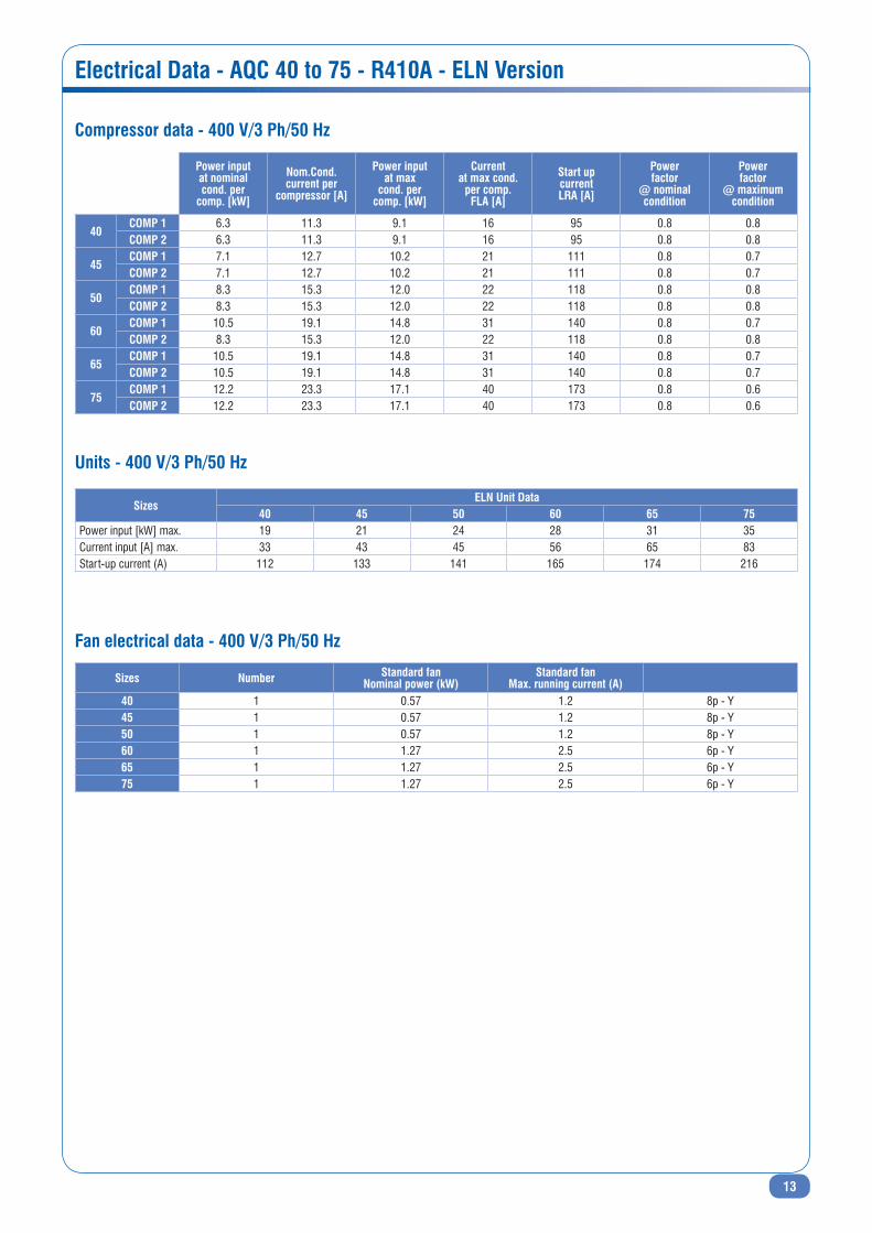
Compressor data - 400 V/3 Ph/50 Hz
units - 400 V/3 Ph/50 Hz
Fan electrical data - 400 V/3 Ph/50 Hz
SizesBLN unit Data
40 45 50 60 65 75Power input [kW] max. 19 21 25 29 32 36Current input [A] max. 34 44 46 57 66 84Start-up current (A) 113 134 142 166 175 217
13
Electrical Data - AQC 40 to 75 - R410A - ELN Version
Sizes Number Standard fanNominal power (kW)
Standard fanmax. running current (A)
40 1 0.57 1.2 8p - Y45 1 0.57 1.2 8p - Y50 1 0.57 1.2 8p - Y60 1 1.27 2.5 6p - Y65 1 1.27 2.5 6p - Y75 1 1.27 2.5 6p - Y
Power inputat nominalcond. per
comp. [kW]
Nom.Cond.current per
compressor [A]
Power inputat max
cond. percomp. [kW]
Currentat max cond.
per comp.FLA [A]
Start upcurrentLRA [A]
Powerfactor
@ nominalcondition
Powerfactor
@ maximumcondition
40 COmP 1 6.3 11.3 9.1 16 95 0.8 0.8COmP 2 6.3 11.3 9.1 16 95 0.8 0.8
45 COmP 1 7.1 12.7 10.2 21 111 0.8 0.7COmP 2 7.1 12.7 10.2 21 111 0.8 0.7
50 COmP 1 8.3 15.3 12.0 22 118 0.8 0.8COmP 2 8.3 15.3 12.0 22 118 0.8 0.8
60 COmP 1 10.5 19.1 14.8 31 140 0.8 0.7COmP 2 8.3 15.3 12.0 22 118 0.8 0.8
65 COmP 1 10.5 19.1 14.8 31 140 0.8 0.7COmP 2 10.5 19.1 14.8 31 140 0.8 0.7
75 COmP 1 12.2 23.3 17.1 40 173 0.8 0.6COmP 2 12.2 23.3 17.1 40 173 0.8 0.6
Compressor data - 400 V/3 Ph/50 Hz
units - 400 V/3 Ph/50 Hz
Fan electrical data - 400 V/3 Ph/50 Hz
SizesELN unit Data
40 45 50 60 65 75Power input [kW] max. 19 21 24 28 31 35Current input [A] max. 33 43 45 56 65 83Start-up current (A) 112 133 141 165 174 216

14
Electrical Data - AQC 40 to 75 - R410A - SIF Version
Sizes Number Standard fanNominal power (kW)
Standard fanmax. running current (A)
40 1 2.67 4.145 1 2.67 4.150 1 2.67 4.160 1 2.67 4.165 1 2.67 4.175 1 2.67 4.1
Power inputat nominalcond. per
comp. [kW]
Nom.Cond.current per
compressor [A]
Power inputat max
cond. percomp. [kW]
Currentat max cond.
per comp.FLA [A]
Start upcurrentLRA [A]
Powerfactor
@ nominalcondition
Powerfactor
@ maximumcondition
40 COmP 1 6.3 11.3 9.1 16 95 0.8 0.8COmP 2 6.3 11.3 9.1 16 95 0.8 0.8
45 COmP 1 7.1 12.7 10.2 21 111 0.8 0.7COmP 2 7.1 12.7 10.2 21 111 0.8 0.7
50 COmP 1 8.3 15.3 12.0 22 118 0.8 0.8COmP 2 8.3 15.3 12.0 22 118 0.8 0.8
60 COmP 1 10.5 19.1 14.8 31 140 0.8 0.7COmP 2 8.3 15.3 12.0 22 118 0.8 0.8
65 COmP 1 10.5 19.1 14.8 31 140 0.8 0.7COmP 2 10.5 19.1 14.8 31 140 0.8 0.7
75 COmP 1 12.2 23.3 17.1 40 173 0.8 0.6COmP 2 12.2 23.3 17.1 40 173 0.8 0.6
Compressor data - 400 V/3 Ph/50 Hz
units - 400 V/3 Ph/50 Hz
Fan electrical data - 400 V/3 Ph/50 Hz
SizesSIF unit Data
40 45 50 60 65 75Power input [kW] max. 21 23 27 29 32 37Current input [A] max. 36 46 48 57 66 84Start-up current (A) 115 136 144 166 175 217

15
Sound Data - AQC 40 to 75 - R410A
Sound power levels - Lw in dB(A) - BLN version
Sound power levels - Lw in dB(A) - ELN version
Sound power levels - Lw in dB(A) - SIF* version
SizesFrequencies (Hz) Lw(A) Global
dB63 125 250 500 1000 2000 4000 8000AQC 40 74.7 91.2 76.6 76.9 74.8 71.0 62.0 55.2 80.5AQC 45 74.9 91.5 76.7 77.5 76.0 71.1 62.1 55.4 81.0AQC 50 74.9 91.5 76.7 77.5 76.0 71.1 62.1 55.4 81.0AQC 60 77.2 94.6 80.7 82.0 81.1 76.2 66.5 59.2 85.5AQC 65 77.1 94.4 80.9 82.5 81.2 76.3 66.7 59.3 85.6AQC 75 77.5 95.0 81.0 82.7 81.1 76.4 66.9 59.5 85.8
SizesFrequencies (Hz) Lw(A) Global
dB63 125 250 500 1000 2000 4000 8000AQC 40 69.5 72.4 70.4 71.3 70.5 65.6 57.0 51.0 74.0AQC 45 73.1 76.4 74.7 73.4 70.9 65.5 58.6 48.3 75.3AQC 50 73.1 76.4 74.7 73.4 70.9 65.5 58.6 48.3 75.3AQC 60 72.3 88.5 75.1 74.0 72.8 68.5 59.1 52.1 78.0AQC 65 73.3 89.6 75.2 74.1 73.0 68.7 59.0 52.0 78.5AQC 75 73.5 89.9 75.5 75.0 73.7 69.2 60.5 53.4 79.0
SizesFrequencies (Hz) Lw(A) Global
dB63 125 250 500 1000 2000 4000 8000AQC 40 82.8 99.1 90.3 93.5 91.4 85.3 75.0 68.5 95.2AQC 45 82.8 99.1 90.3 93.5 91.4 85.3 75.0 68.5 95.2AQC 50 82.8 99.1 90.3 93.5 91.4 85.3 75.0 68.5 95.2AQC 60 83.1 99.9 90.4 93.6 91.5 85.4 75.1 68.7 95.3AQC 65 83.1 99.9 90.4 93.6 91.5 85.4 75.1 68.7 95.3AQC 75 83.1 99.9 90.4 93.6 91.5 85.4 75.1 68.7 95.3
* Sound data referred to a fan speed of 1110 rpm.Compressor jacket (standard on ELN) can be ordered as accessory. Compressor jacket impact = -2 dB(A).

16
Sound Data - AQC 40 to 75 - R410A (continued)
Sound pressure levels - Lp in dB(A) - BLN version
Sound pressure levels - Lp in dB(A) - ELN version
Sound pressure levels - Lp in dB(A) - SIF* version
SizesFrequencies (Hz) Lp(A) Global
dB63 125 250 500 1000 2000 4000 8000AQC 40 43.1 59.6 45.0 45.3 43.2 39.4 30.4 23.6 48.9AQC 45 43.3 59.9 45.1 45.9 44.4 39.5 30.5 23.8 49.4AQC 50 43.3 59.9 45.1 45.9 44.4 39.5 30.5 23.8 49.4AQC 60 45.5 62.9 49.0 50.3 49.4 44.5 34.8 27.5 53.8AQC 65 45.4 62.7 49.2 50.8 49.5 44.6 35.0 27.6 53.9AQC 75 45.8 63.3 49.3 51.0 49.4 44.7 35.2 27.8 54.1
SizesFrequencies (Hz) Lp(A) Global
dB63 125 250 500 1000 2000 4000 8000AQC 40 51.2 67.5 58.7 61.9 59.8 53.7 43.4 36.9 63.6AQC 45 51.2 67.5 58.7 61.9 59.8 53.7 43.4 36.9 63.6AQC 50 51.2 67.5 58.7 61.9 59.8 53.7 43.4 36.9 63.6AQC 60 51.4 68.2 58.7 61.9 59.8 53.7 43.4 37.0 63.6AQC 65 51.4 68.2 58.7 61.9 59.8 53.7 43.4 37.0 63.6AQC 75 51.4 68.2 58.7 61.9 59.8 53.7 43.4 37.0 63.6
SizesFrequencies (Hz) Lp(A) Global
dB63 125 250 500 1000 2000 4000 8000AQC 40 37.9 40.8 38.8 39.7 38.9 34.0 25.4 19.4 42.4AQC 45 41.5 44.8 43.1 41.8 39.3 33.9 27.0 16.7 43.7AQC 50 41.5 44.8 43.1 41.8 39.3 33.9 27.0 16.7 43.7AQC 60 40.6 56.8 43.4 42.3 41.1 36.8 27.4 20.4 46.3AQC 65 41.6 57.9 43.5 42.4 41.3 37.0 27.3 20.3 46.8AQC 75 41.8 58.2 43.8 43.3 42.0 37.5 28.8 21.7 47.3
Sound pressure level calculated at a distance of 10 metre. Sound pressure levels refer to ISO standard 3744 with parallepiped shape.* Sound data referred to a fan speed of 1110 rpm.Compressor jacket (standard on ELN) can be ordered as accessory. Compressor jacket impact = -2 dB(A).

17
Performance Data - AQC 40 to 75 - R410A - BLN Version
AQCBLNsizes
Et (°C)
Ambient air temperature (°C)25 30 32 35 40 43 46
Cool.cap.(kW)
Inputpower*
(kW)
Cool.cap.(kW)
Inputpower*
(kW)
Cool.cap.(kW)
Inputpower*
(kW)
Cool.cap.(kW)
Inputpower*
(kW)
Cool.cap.(kW)
Inputpower*
(kW)
Cool.cap.(kW)
Inputpower*
(kW)
Cool.cap.(kW)
Inputpower*
(kW)
AQC40
BLN
1 40.9 10.1 38.6 11.1 37.8 11.6 36.3 12.2 33.9 13.4 32.4 14.2 30.8 15.03 43.5 10.4 41.0 11.3 40.1 11.8 38.6 12.5 35.9 13.6 34.4 14.4 32.8 15.15 46.0 10.6 43.5 11.6 42.5 12.0 40.9 12.7 38.1 13.8 36.4 14.67 48.7 10.9 46.0 11.9 44.9 12.3 43.2 13.0 40.3 14.1 38.6 14.89 51.6 11.1 48.6 12.1 47.5 12.5 45.6 13.2 42.7 14.4 40.8 15.111 54.4 11.4 51.4 12.4 50.2 12.8 48.1 13.5 45.1 14.714 58.9 11.8 54.1 12.7 52.8 13.1 52.2 14.1 48.9 15.3
AQC45
BLN
1 46.3 12.0 43.7 13.1 42.7 13.7 41.1 14.5 38.4 15.8 36.6 16.8 34.9 17.73 49.2 12.3 46.4 13.4 45.4 14.0 43.6 14.8 40.6 16.1 38.9 17.0 37.1 17.95 52.1 12.6 49.2 13.7 48.1 14.2 46.3 15.1 43.1 16.3 41.2 17.37 55.2 12.9 52.0 14.1 50.9 14.6 48.8 15.3 45.6 16.7 43.6 17.59 58.4 13.1 55.0 14.4 53.8 14.8 51.6 15.6 48.3 17.0 46.1 17.911 61.6 13.5 58.2 14.7 56.8 15.2 54.5 16.0 51.0 17.414 66.6 14.0 61.3 15.0 59.7 15.6 59.1 16.6 55.4 18.1
AQC50
BLN
1 53.9 13.9 50.9 15.2 49.8 15.9 47.9 16.8 44.7 18.4 42.7 19.4 40.7 20.53 57.3 14.3 54.1 15.6 52.9 16.2 50.9 17.1 47.4 18.7 45.3 19.8 43.2 20.85 60.7 14.6 57.3 15.9 56.0 16.5 53.9 17.5 50.2 19.0 48.0 20.07 64.3 14.9 60.7 16.3 59.3 16.9 56.9 17.8 53.2 19.4 50.9 20.49 68.0 15.2 64.1 16.6 62.7 17.2 60.2 18.1 56.3 19.8 53.8 20.811 71.7 15.7 67.8 17.1 66.2 17.6 63.5 18.5 59.4 20.214 77.7 16.2 71.4 17.4 69.6 18.0 68.9 19.3 64.5 21.0
AQC60
BLN
1 63.9 14.7 60.3 16.0 59.0 16.7 56.7 17.7 52.9 19.3 50.5 20.5 48.1 21.63 67.9 15.0 64.1 16.4 62.6 17.1 60.2 18.0 56.1 19.7 53.7 20.8 51.2 21.95 71.9 15.4 67.9 16.7 66.4 17.4 63.9 18.4 59.5 20.0 56.9 21.17 76.1 15.7 71.8 17.2 70.2 17.8 67.4 18.7 63.0 20.4 60.2 21.49 80.6 16.0 75.9 17.5 74.2 18.1 71.3 19.1 66.7 20.8 63.7 21.9
11 85.0 16.5 80.3 18.0 78.4 18.6 75.2 19.5 70.4 21.314 92.0 17.1 84.6 18.3 82.5 19.0 81.6 20.3 76.4 22.1
AQC65
BLN
1 69.9 16.9 66.0 18.5 64.6 19.3 62.1 20.4 58.0 22.3 55.3 23.6 52.7 24.93 74.3 17.3 70.1 18.9 68.6 19.7 65.9 20.8 61.4 22.7 58.8 24.0 56.1 25.15 78.8 17.7 74.3 19.3 72.7 20.0 69.9 21.2 65.1 23.0 62.3 24.37 83.4 18.1 78.6 19.8 76.9 20.5 73.8 21.6 69.0 23.5 65.9 24.79 88.2 18.5 83.1 20.2 81.3 20.9 78.0 22.0 73.0 24.0 69.7 25.111 93.0 19.0 87.9 20.7 85.8 21.4 82.3 22.5 77.1 24.514 100.7 19.7 92.6 21.1 90.3 21.9 89.4 23.4 83.7 25.4
AQC75
BLN
1 80.0 20.6 75.6 22.5 73.9 23.5 71.0 24.8 66.3 27.2 63.3 28.7 60.3 30.33 85.1 21.1 80.2 23.0 78.4 24.0 75.4 25.3 70.3 27.6 67.3 29.2 64.1 30.75 90.1 21.5 85.1 23.5 83.1 24.4 80.0 25.8 74.5 28.0 71.2 29.67 95.4 22.0 90.0 24.1 87.9 25.0 84.5 26.3 78.9 28.6 75.4 30.19 100.9 22.5 95.0 24.6 93.0 25.4 89.3 26.8 83.5 29.2 79.8 30.711 106.4 23.1 100.5 25.2 98.1 26.1 94.2 27.4 88.2 29.814 115.2 24.0 106.0 25.7 103.3 26.7 102.2 28.5 95.7 31.0
* Compressors only.Et : Evaporating temperature.

18
Performance Data - AQC 40 to 75 - R410A - ELN Version
AQCELNsizes
Et (°C)
Ambient air temperature (°C)25 30 32 35 40 43
Cool.cap.(kW)
Inputpower*
(kW)
Cool.cap.(kW)
Inputpower*
(kW)
Cool.cap.(kW)
Inputpower*
(kW)
Cool.cap.(kW)
Inputpower*
(kW)
Cool.cap.(kW)
Inputpower*
(kW)
Cool.cap.(kW)
Inputpower*
(kW)
AQC40
ELN
1 39.4 10.7 37.3 11.7 36.4 12.2 35.0 12.9 32.7 14.1 31.2 14.93 41.9 10.9 39.6 12.0 38.7 12.5 37.2 13.2 34.6 14.4 33.2 15.25 44.4 11.2 41.9 12.2 41.0 12.7 39.4 13.4 36.7 14.57 47.0 11.4 44.4 12.5 43.4 13.0 41.6 13.7 38.9 14.99 49.8 11.7 46.9 12.8 45.8 13.2 44.0 13.9 41.2 15.211 52.5 12.0 49.6 13.1 48.4 13.5 46.4 14.214 56.8 12.5 52.2 13.3 50.9 13.9 50.4 14.8
AQC45
ELN
1 44.3 12.8 41.8 14.0 40.9 14.6 39.3 15.4 36.7 16.8 35.0 17.83 47.1 13.1 44.4 14.3 43.4 14.9 41.8 15.7 38.9 17.1 37.2 18.15 49.9 13.4 47.1 14.6 46.0 15.1 44.3 16.0 41.2 17.47 52.8 13.7 49.8 14.9 48.7 15.5 46.7 16.3 43.7 17.79 55.9 14.0 52.6 15.2 51.5 15.8 49.4 16.6 46.2 18.111 58.9 14.3 55.7 15.6 54.3 16.1 52.1 17.014 63.8 14.9 58.6 15.9 57.2 16.5 56.6 17.7
AQC50
ELN
1 51.1 15.0 48.3 16.4 47.2 17.1 45.4 18.1 42.4 19.7 40.5 20.93 54.4 15.3 51.3 16.7 50.1 17.4 48.2 18.4 44.9 20.1 43.0 21.25 57.6 15.7 54.4 17.1 53.1 17.7 51.1 18.8 47.6 20.47 61.0 16.0 57.5 17.5 56.2 18.1 54.0 19.1 50.4 20.89 64.5 16.4 60.7 17.9 59.4 18.5 57.0 19.5 53.4 21.211 68.0 16.8 64.3 18.3 62.7 18.9 60.2 19.914 73.6 17.4 67.7 18.7 66.0 19.4 65.3 20.7
AQC60
ELN
1 61.5 15.4 58.1 16.9 56.8 17.6 54.5 18.6 50.9 20.4 48.6 21.63 65.3 15.8 61.7 17.3 60.3 18.0 58.0 19.0 54.0 20.8 51.7 21.95 69.2 16.2 65.3 17.6 63.9 18.3 61.5 19.4 57.2 21.07 73.3 16.5 69.1 18.1 67.6 18.7 64.9 19.7 60.6 21.59 77.5 16.9 73.0 18.5 71.4 19.1 68.6 20.1 64.1 21.911 81.8 17.4 77.3 18.9 75.4 19.6 72.4 20.614 88.5 18.0 81.4 19.3 79.4 20.0 78.5 21.4
AQC65
ELN
1 67.0 17.8 63.3 19.5 61.9 20.3 59.5 21.5 55.5 23.5 53.0 24.93 71.2 18.2 67.2 19.9 65.7 20.8 63.2 21.9 58.9 23.9 56.3 25.35 75.5 18.6 71.2 20.3 69.6 21.1 67.0 22.3 62.4 24.27 79.9 19.1 75.4 20.9 73.7 21.6 70.7 22.8 66.1 24.89 84.5 19.5 79.6 21.3 77.9 22.0 74.8 23.2 69.9 25.311 89.1 20.0 84.2 21.8 82.2 22.5 78.9 23.714 96.5 20.8 88.7 22.2 86.5 23.1 85.6 24.6
AQC75
ELN
1 76.3 22.0 72.1 24.1 70.5 25.1 67.7 26.5 63.3 29.0 60.4 30.73 81.1 22.5 76.6 24.6 74.8 25.6 72.0 27.1 67.0 29.5 64.2 31.25 86.0 23.0 81.1 25.1 79.3 26.0 76.3 27.6 71.1 29.97 91.0 23.5 85.8 25.8 83.9 26.7 80.6 28.1 75.3 30.69 96.3 24.1 90.7 26.3 88.7 27.2 85.2 28.6 79.7 31.211 101.5 24.7 95.9 26.9 93.6 27.8 89.9 29.314 109.9 25.6 101.1 27.4 98.6 28.5 97.5 30.4
* Compressors only.Et : Evaporating temperature.
19
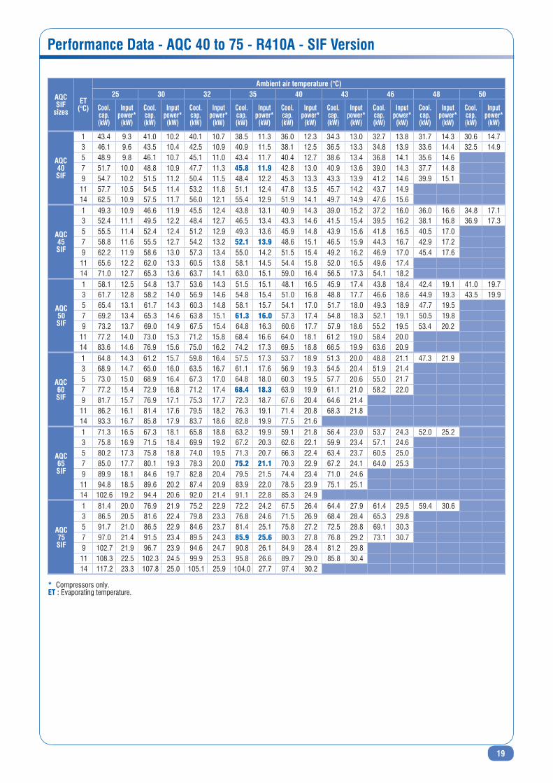
Performance Data - AQC 40 to 75 - R410A - SIF Version
AQCSIF
sizesEt
(°C)
Ambient air temperature (°C)25 30 32 35 40 43 46 48 50
Cool.cap. (kW)
Inputpower*
(kW)
Cool.cap. (kW)
Inputpower*
(kW)
Cool.cap. (kW)
Inputpower*
(kW)
Cool.cap. (kW)
Inputpower*
(kW)
Cool.cap. (kW)
Inputpower*
(kW)
Cool.cap. (kW)
Inputpower*
(kW)
Cool.cap. (kW)
Inputpower*
(kW)
Cool.cap. (kW)
Inputpower*
(kW)
Cool.cap. (kW)
Inputpower*
(kW)
AQC40SIF
1 43.4 9.3 41.0 10.2 40.1 10.7 38.5 11.3 36.0 12.3 34.3 13.0 32.7 13.8 31.7 14.3 30.6 14.73 46.1 9.6 43.5 10.4 42.5 10.9 40.9 11.5 38.1 12.5 36.5 13.3 34.8 13.9 33.6 14.4 32.5 14.95 48.9 9.8 46.1 10.7 45.1 11.0 43.4 11.7 40.4 12.7 38.6 13.4 36.8 14.1 35.6 14.67 51.7 10.0 48.8 10.9 47.7 11.3 45.8 11.9 42.8 13.0 40.9 13.6 39.0 14.3 37.7 14.89 54.7 10.2 51.5 11.2 50.4 11.5 48.4 12.2 45.3 13.3 43.3 13.9 41.2 14.6 39.9 15.111 57.7 10.5 54.5 11.4 53.2 11.8 51.1 12.4 47.8 13.5 45.7 14.2 43.7 14.914 62.5 10.9 57.5 11.7 56.0 12.1 55.4 12.9 51.9 14.1 49.7 14.9 47.6 15.6
AQC45SIF
1 49.3 10.9 46.6 11.9 45.5 12.4 43.8 13.1 40.9 14.3 39.0 15.2 37.2 16.0 36.0 16.6 34.8 17.13 52.4 11.1 49.5 12.2 48.4 12.7 46.5 13.4 43.3 14.6 41.5 15.4 39.5 16.2 38.1 16.8 36.9 17.35 55.5 11.4 52.4 12.4 51.2 12.9 49.3 13.6 45.9 14.8 43.9 15.6 41.8 16.5 40.5 17.07 58.8 11.6 55.5 12.7 54.2 13.2 52.1 13.9 48.6 15.1 46.5 15.9 44.3 16.7 42.9 17.29 62.2 11.9 58.6 13.0 57.3 13.4 55.0 14.2 51.5 15.4 49.2 16.2 46.9 17.0 45.4 17.611 65.6 12.2 62.0 13.3 60.5 13.8 58.1 14.5 54.4 15.8 52.0 16.5 49.6 17.414 71.0 12.7 65.3 13.6 63.7 14.1 63.0 15.1 59.0 16.4 56.5 17.3 54.1 18.2
AQC50SIF
1 58.1 12.5 54.8 13.7 53.6 14.3 51.5 15.1 48.1 16.5 45.9 17.4 43.8 18.4 42.4 19.1 41.0 19.73 61.7 12.8 58.2 14.0 56.9 14.6 54.8 15.4 51.0 16.8 48.8 17.7 46.6 18.6 44.9 19.3 43.5 19.95 65.4 13.1 61.7 14.3 60.3 14.8 58.1 15.7 54.1 17.0 51.7 18.0 49.3 18.9 47.7 19.57 69.2 13.4 65.3 14.6 63.8 15.1 61.3 16.0 57.3 17.4 54.8 18.3 52.1 19.1 50.5 19.89 73.2 13.7 69.0 14.9 67.5 15.4 64.8 16.3 60.6 17.7 57.9 18.6 55.2 19.5 53.4 20.2
11 77.2 14.0 73.0 15.3 71.2 15.8 68.4 16.6 64.0 18.1 61.2 19.0 58.4 20.014 83.6 14.6 76.9 15.6 75.0 16.2 74.2 17.3 69.5 18.8 66.5 19.9 63.6 20.9
AQC60SIF
1 64.8 14.3 61.2 15.7 59.8 16.4 57.5 17.3 53.7 18.9 51.3 20.0 48.8 21.1 47.3 21.93 68.9 14.7 65.0 16.0 63.5 16.7 61.1 17.6 56.9 19.3 54.5 20.4 51.9 21.45 73.0 15.0 68.9 16.4 67.3 17.0 64.8 18.0 60.3 19.5 57.7 20.6 55.0 21.77 77.2 15.4 72.9 16.8 71.2 17.4 68.4 18.3 63.9 19.9 61.1 21.0 58.2 22.09 81.7 15.7 76.9 17.1 75.3 17.7 72.3 18.7 67.6 20.4 64.6 21.411 86.2 16.1 81.4 17.6 79.5 18.2 76.3 19.1 71.4 20.8 68.3 21.814 93.3 16.7 85.8 17.9 83.7 18.6 82.8 19.9 77.5 21.6
AQC65SIF
1 71.3 16.5 67.3 18.1 65.8 18.8 63.2 19.9 59.1 21.8 56.4 23.0 53.7 24.3 52.0 25.23 75.8 16.9 71.5 18.4 69.9 19.2 67.2 20.3 62.6 22.1 59.9 23.4 57.1 24.65 80.2 17.3 75.8 18.8 74.0 19.5 71.3 20.7 66.3 22.4 63.4 23.7 60.5 25.07 85.0 17.7 80.1 19.3 78.3 20.0 75.2 21.1 70.3 22.9 67.2 24.1 64.0 25.39 89.9 18.1 84.6 19.7 82.8 20.4 79.5 21.5 74.4 23.4 71.0 24.611 94.8 18.5 89.6 20.2 87.4 20.9 83.9 22.0 78.5 23.9 75.1 25.114 102.6 19.2 94.4 20.6 92.0 21.4 91.1 22.8 85.3 24.9
AQC75SIF
1 81.4 20.0 76.9 21.9 75.2 22.9 72.2 24.2 67.5 26.4 64.4 27.9 61.4 29.5 59.4 30.63 86.5 20.5 81.6 22.4 79.8 23.3 76.8 24.6 71.5 26.9 68.4 28.4 65.3 29.85 91.7 21.0 86.5 22.9 84.6 23.7 81.4 25.1 75.8 27.2 72.5 28.8 69.1 30.37 97.0 21.4 91.5 23.4 89.5 24.3 85.9 25.6 80.3 27.8 76.8 29.2 73.1 30.79 102.7 21.9 96.7 23.9 94.6 24.7 90.8 26.1 84.9 28.4 81.2 29.811 108.3 22.5 102.3 24.5 99.9 25.3 95.8 26.6 89.7 29.0 85.8 30.414 117.2 23.3 107.8 25.0 105.1 25.9 104.0 27.7 97.4 30.2
* Compressors only.Et : Evaporating temperature.

20
Dimensions (mm) - AQC 40 to 50 - R410A
1355
1395 16
8515
80
C
D
4 x Ø22
1100
2310
5423
1750
517
112 1121527
987
987
1100
P2
P1
P3
P4
50 1000 50
25
IL
H
F
G
61275
2310
5423 112 1527 112
P3
P4
P2
P1 4 x Ø10
Q R
241
Front view
Bottom view
Side view top view
C Electrical auxiliary linesD Electrical power supplyF High pressure tapG Low pressure tapH Gauge kit (accessory)I Main switchL Control keypad/display
XXX Only for SIF fan modelP1, P2, P3, P4 AVM position
Q Liquid line Ø 5/8"R Suction line Ø 1 3/8"

21
50 1000 50
25
L I
H
F
G
69875
1355
1395 16
85
1580
C
D
4 x Ø22
112 1977 112
2323
1054
P2
P1
P3
P44 x Ø10
987
1121977
2200
698
987
2310
5423
1100
112
1100
P2
P3
P1
P4241
Q R
Front view
Bottom view
Side view top view
C Electrical auxiliary linesD Electrical power supplyF High pressure tapG Low pressure tapH Gauge kit (accessory)I Main switchL Control keypad/display
XXX Only for SIF fan modelP1, P2, P3, P4 AVM position
Q Liquid line Ø 7/8"R Suction line Ø 1 3/8"
Dimensions (mm) - AQC 60 to 75 - R410A
22
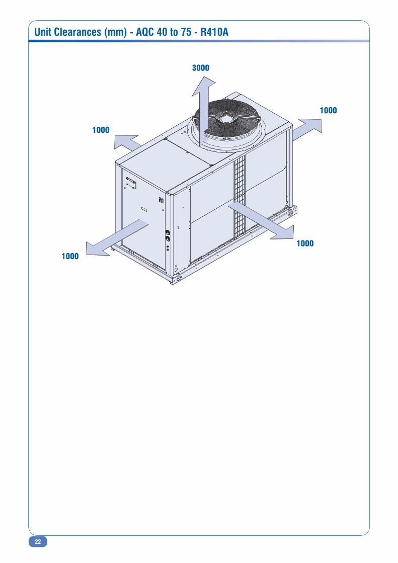
unit Clearances (mm) - AQC 40 to 75 - R410A
3000
1000
1000
1000
1000

23
Notes

Syst
emai
r AC
· Feb
ruar
y 20
12 ·
EDM
AQ
C-S.
1GB/
02.1
2As
par
t of o
ur o
ngoi
ng p
rodu
ct im
prov
emen
t pro
gram
me,
our
pro
duct
s ar
e su
bjec
t to
chan
ge w
ithou
t prio
r not
ice.
Non
con
trac
tual
pho
tos.
Systemair AC srlVia XXV Aprile, 2920825 Barlassina (MB) Italy
Tel. +39 0362 680 1Fax +39 0362 680 693