agilent valve kit g4231a/b and g4232b/c · agilent valve kit g4231a/b and g4232b/c ... drug...
TRANSCRIPT
Agilent Valve Kit G4231A/B and G4232B/C
Instructions
Agilent Valve Kit G4231A/B and G4232B/C - InstructionsTechnical Information about the Agilent Valve Kits G4231A/B and G4232B/C and the installation of the low dispersion heat- exchanger double assemblies.
Contents
Typical Applications 2
Dual column selection (2pos/6port or 2pos/10port valves) 2Sample enrichment and sample cleanup (2pos/6port or 2pos/10port valves) 3Alternating Column Regeneration (2pos/10port valves only) 4
Delivery Checklist 5
Specifications 8
Installation 9
Installation of the Valve Heads 9Connecting Valves, Heat Exchanger and Columns 13
Replacement Parts 20
Agilent Technologies

Typical Applications Dual column selection (2pos/6port or 2pos/10port valves)
Typical Applications
2
NOTE Which ports are interconnected at which valve position strongly depends on the module the valve is installed to. The software user interface will always display the correct situation. A method modification or re-plumbing of the connections is typically required if transferring methods from a G1316A/B/C to a G7116B, G1170A or G4227A.
Refer to the table below for further information on which ports are connected at which position.
Modules Valve Position 1 Position 2
G1316A/B/C 2pos/6port 1-2 1-6
G7116B, G1170A, G4227A 2pos/6port 1-6 1-2
G1316A/B/C 2pos/10port 1-2 1-10
G7116B, G1170A, G4227A 2pos/10port 1-10 1-2
Dual column selection (2pos/6port or 2pos/10port valves)
Advantages:
• Increase productivity
• Higher instrument up- time
Quickly change between two different stationary phases to check your separation selectivity, or use two identical stationary phases to have the second column immediately available after the first one loses efficiency, for example with complex matrices.
Typical ApplicationsSample enrichment and sample cleanup (2pos/6port or 2pos/10port valves)
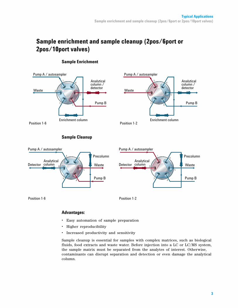
Sample enrichment and sample cleanup (2pos/6port or 2pos/10port valves)
Sample Enrichment
Sample Cleanup
Advantages:
• Easy automation of sample preparation
• Higher reproducibility
• Increased productivity and sensitivity
Sample cleanup is essential for samples with complex matrices, such as biological fluids, food extracts and waste water. Before injection into a LC or LC/MS system, the sample matrix must be separated from the analytes of interest. Otherwise, contaminants can disrupt separation and detection or even damage the analytical column.
3
4
Typical Applications Alternating Column Regeneration (2pos/10port valves only)
Enrichment methods
Enrichment methods are the technique of choice to obtain highest sensitivity and to remove the sample matrix in such applications as proteomics, drug metabolism and environmental trace analysis. The analytes are retained and concentrated onto the pre- column, while the sample matrix is passed to waste. After the valve switch, a second pump backflushes the analytes out of the pre- column onto the separation column. This allows injection of large volumes onto the pre- column, significantly expanding sensitivity in the range of ten to several thousands.
Stripping methods
Stripping methods handle analytes and matrices in the opposite way to enrichment methods. Matrix components are retained on the pre- column while the analytes pass through to the separation column. After the valve switches, an additional pump backflushes the matrix components out of the pre- column to waste, while the analytes are separated on the main column. Backflushing prepares the pre- column for the next injection.
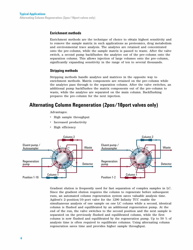
Alternating Column Regeneration (2pos/10port valves only)
Advantages:• High sample throughput
• Increased productivity
• High efficiency
Gradient elution is frequently used for fast separation of complex samples in LC. Since the gradient elution requires the column to regenerate before subsequent runs, an automated column regeneration system saves valuable analysis time. Agilent's 2- position/10- port valve for the 1290 Infinity TCC enable the simultaneous analysis of one sample on one LC column while a second, identical column is flushed and equilibrated by an additional regeneration pump. At the end of the run, the valve switches to the second position and the next sample is separated on the previously flushed and equilibrated column, while the first column is now flushed and equilibrated by the regeneration pump. Up to 50 % of analysis time is often required to equilibrate columns. Using alternating column regeneration saves time and provides higher sample throughput.
Delivery ChecklistAlternating Column Regeneration (2pos/10port valves only)
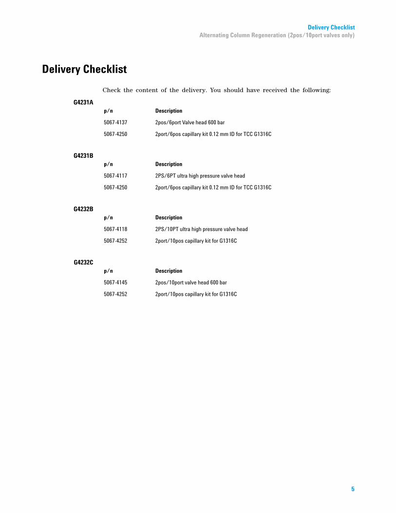
Delivery Checklist
Check the content of the delivery. You should have received the following:
G4231A
p/n Description5067-4137 2pos/6port Valve head 600 bar
5067-4250 2port/6pos capillary kit 0.12 mm ID for TCC G1316C
G4231B
p/n Description5067-4117 2PS/6PT ultra high pressure valve head
5067-4250 2port/6pos capillary kit 0.12 mm ID for TCC G1316C
G4232B
p/n Description5067-4118 2PS/10PT ultra high pressure valve head
5067-4252 2port/10pos capillary kit for G1316C
G4232C
p/n Description5067-4145 2pos/10port valve head 600 bar
5067-4252 2port/10pos capillary kit for G1316C
5
Delivery Checklist Capillary kit PN 5067-4250
Capillary kit PN 5067-4250
6
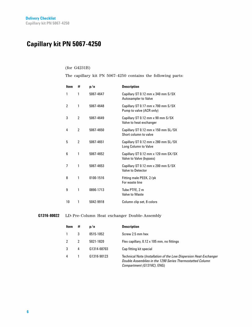
(for G4231B)
The capillary kit PN 5067- 4250 contains the following parts:
Item # p/n Description
1 1 5067-4647 Capillary ST 0.12 mm x 340 mm S/SXAutosampler to Valve
2 1 5067-4648 Capillary ST 0.17 mm x 700 mm S/SXPump to valve (ACR only)
3 2 5067-4649 Capillary ST 0.12 mm x 90 mm S/SXValve to heat exchanger
4 2 5067-4650 Capillary ST 0.12 mm x 150 mm SL/SXShort column to valve
5 2 5067-4651 Capillary ST 0.12 mm x 280 mm SL/SXLong Column to Valve
6 1 5067-4652 Capillary ST 0.12 mm x 120 mm SX/SXValve to Valve (bypass)
7 1 5067-4653 Capillary ST 0.12 mm x 200 mm S/SXValve to Detector
8 1 0100-1516 Fitting male PEEK, 2/pkFor waste line
9 1 0890-1713 Tube PTFE, 2 mValve to Waste
10 1 5042-9918 Column clip set, 8 colors
G1316-80022
LD- Pre- Column Heat exchanger Double- AssemblyItem # p/n Description
1 3 0515-1052 Screw 2.5 mm hex
2 2 5021-1820 Flex capillary, 0.12 x 105 mm, no fittings
3 4 G1314-68703 Cap fitting kit special
4 1 G1316-90123 Technical Note (Installation of the Low Dispersion Heat-Exchanger Double Assemblies in the 1290 Series Thermostatted Column Compartment (G1316C), ENG)
Delivery ChecklistCapillary kit PN 5067-4252
Capillary kit PN 5067-4252
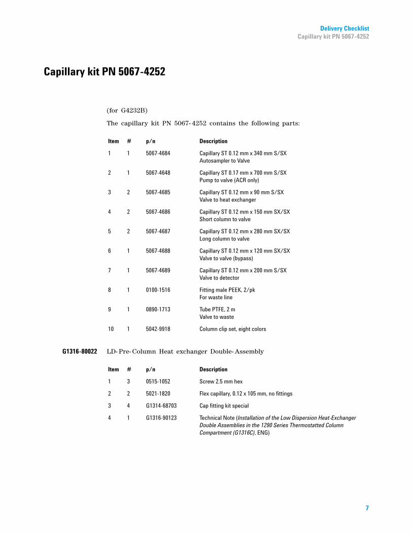
(for G4232B)
The capillary kit PN 5067- 4252 contains the following parts:
Item # p/n Description
1 1 5067-4684 Capillary ST 0.12 mm x 340 mm S/SXAutosampler to Valve
2 1 5067-4648 Capillary ST 0.17 mm x 700 mm S/SXPump to valve (ACR only)
3 2 5067-4685 Capillary ST 0.12 mm x 90 mm S/SXValve to heat exchanger
4 2 5067-4686 Capillary ST 0.12 mm x 150 mm SX/SXShort column to valve
5 2 5067-4687 Capillary ST 0.12 mm x 280 mm SX/SXLong column to valve
6 1 5067-4688 Capillary ST 0.12 mm x 120 mm SX/SXValve to valve (bypass)
7 1 5067-4689 Capillary ST 0.12 mm x 200 mm S/SXValve to detector
8 1 0100-1516 Fitting male PEEK, 2/pkFor waste line
9 1 0890-1713 Tube PTFE, 2 mValve to waste
10 1 5042-9918 Column clip set, eight colors
G1316-80022
LD- Pre- Column Heat exchanger Double- AssemblyItem # p/n Description
1 3 0515-1052 Screw 2.5 mm hex
2 2 5021-1820 Flex capillary, 0.12 x 105 mm, no fittings
3 4 G1314-68703 Cap fitting kit special
4 1 G1316-90123 Technical Note (Installation of the Low Dispersion Heat-Exchanger Double Assemblies in the 1290 Series Thermostatted Column Compartment (G1316C), ENG)
7
Specifications Capillary kit PN 5067-4252
Specifications
8
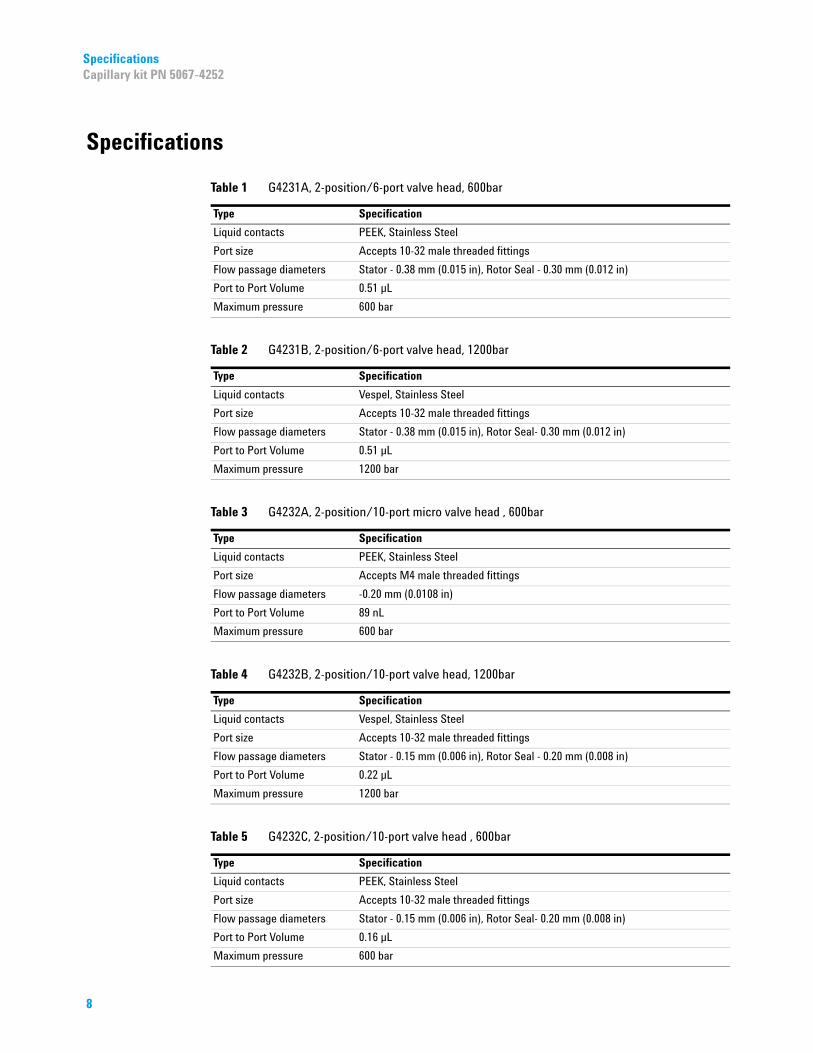
Table 1 G4231A, 2-position/6-port valve head, 600bar
Type Specification
Liquid contacts PEEK, Stainless Steel
Port size Accepts 10-32 male threaded fittings
Flow passage diameters Stator - 0.38 mm (0.015 in), Rotor Seal - 0.30 mm (0.012 in)
Port to Port Volume 0.51 µL
Maximum pressure 600 bar
Table 2 G4231B, 2-position/6-port valve head, 1200bar
Type Specification
Liquid contacts Vespel, Stainless Steel
Port size Accepts 10-32 male threaded fittings
Flow passage diameters Stator - 0.38 mm (0.015 in), Rotor Seal- 0.30 mm (0.012 in)
Port to Port Volume 0.51 µL
Maximum pressure 1200 bar
Table 3 G4232A, 2-position/10-port micro valve head , 600bar
Type Specification
Liquid contacts PEEK, Stainless Steel
Port size Accepts M4 male threaded fittings
Flow passage diameters -0.20 mm (0.0108 in)
Port to Port Volume 89 nL
Maximum pressure 600 bar
Table 4 G4232B, 2-position/10-port valve head, 1200bar
Type Specification
Liquid contacts Vespel, Stainless Steel
Port size Accepts 10-32 male threaded fittings
Flow passage diameters Stator - 0.15 mm (0.006 in), Rotor Seal - 0.20 mm (0.008 in)
Port to Port Volume 0.22 µL
Maximum pressure 1200 bar
Table 5 G4232C, 2-position/10-port valve head , 600bar
Type Specification
Liquid contacts PEEK, Stainless Steel
Port size Accepts 10-32 male threaded fittings
Flow passage diameters Stator - 0.15 mm (0.006 in), Rotor Seal- 0.20 mm (0.008 in)
Port to Port Volume 0.16 µL
Maximum pressure 600 bar
InstallationInstallation of the Valve Heads
Installation
Installation of the Valve Heads
The valve drives are factory- installed in the 1290 Infinity Thermostatted Column Compartment , in the 1290 Infinity Flexible Cube, and in the 1290 Infinity Universal Valve Drive. The valve heads are interchangeable and can be easily mounted.
At the first installation, the transportation lock (TCC only) and the dummy valve have to be removed, see “Removing the transportation lock and the valve dummy” on page 9. The valve heads can be installed by mounting the valve heads onto the valve drives and fastening the nut manually (do not use any tools).
Be sure that the guide pin snaps into the groove of the valve drive thread.
NOTE TCC only:
The valves are mounted on pull-out rails to allow easy installation of capillaries. Push the valve gently into its housing until it snaps into the inner position, push it again and it slides out.
If all capillaries are installed, push the valve back into its housing, see section Installing the Valve Head and Connecting Capillaries in the TCC-Manual.
Removing the transportation lock and the valve dummyThe following procedure demonstrates the necessary steps for installing the valve head to the valve drive of a TCC.
For the installation of a valve head to a G1170A 1290 Infinity Valve Drive or G4227A 1290 Infinity Flexible Cube you can ignore the steps that describe the TCC features of the transportation lock and spring loaded valve drive.
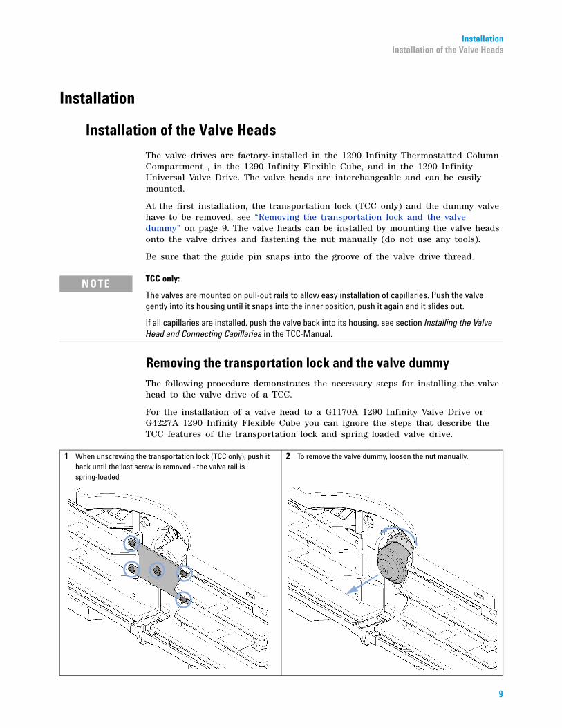
1 When unscrewing the transportation lock (TCC only), push it back until the last screw is removed - the valve rail is spring-loaded
2 To remove the valve dummy, loosen the nut manually.
9
10
Installation Installation of the Valve Heads
Installing the valve head and connecting capillaries
For bio-inert modules use bio-inert parts only!
The valve actuator contains sensitive optical parts, which need to be protected from dust and
other pollutions. Pollution of these parts can impair the accurate selection of valve ports and therefore bias measurement results.➔ Always install a valve head for operation and storage. For protecting the actuator, a dummy valve head can be used instead of a functional valve. Do not touch parts inside the actuator.
CAUTION
Column Damage or Bias Measurement Results
Switching the valve to a wrong position can damage the column or bias measurement results.
➔ Fit the lobe to the groove to make sure the valve is switched to the correct position.
CAUTION
Valve Damage
Using a low pressure valve on the high pressure side can damage the valve.
➔ When using multiple column compartments as part of a method development solution, make sure that the high pressure valve head is connected to the autosampler and the low pressure valve head is connected to the detector.
CAUTION
Sample degradation and contamination of the instrument
Metal parts in the flow path can interact with the bio-molecules in the sample leading to sample degradation and contamination.
➔ For bio-inert applications, always use dedicated bio-inert parts, which can be identified by the bio-inert symbol or other markers described in this manual.
➔ Do not mix bio-inert and non-inert modules or parts in a bio-inert system.
CAUTION
NOTE The tag reader reads the valve head properties from the valve head RFID tag during the initialization of the module. The valve properties will not be updated if the valve head is replaced while the module is on. Selection of valve port positions can fail if the instrument does not know the properties of the installed valve.
NOTE The Agilent 1290 Infinity Valve Drive recognizes the valve correctly, only if the valve drive was powered off for at least 10 s.

InstallationInstallation of the Valve Heads
NOTE For a correct installation of the valve head, the outside pin (red) must completely fit into the outside groove on the valve drive’s shaft (red). A correct installation is only possible if the two pins (green and blue) on the valve head fit into their corresponding grooves on the valve drive’s actuator axis. Their match depends on the diameter of the pin and groove.
The following procedure demonstrates the necessary steps for installing the valve head to the valve drive of a TCC. For the installation of a valve head to a 1290 Infinity Valve Drive or 1290 Infinity Flexible Cube, you can ignore the steps that describe the TCC features of the spring loaded valve drive.
1 Insert the valve head into the valve shaft.
ORIf the outside pin does not fit into the outside groove, you have to turn the valve head until you feel that the two pins snap into the grooves. Now you should feel additional resistance from the valve drive while continue turning the valve head until the pin fits into the groove.
2 When the outer pin is locked into the groove, manually screw the nut onto the valve head.
NOTEFasten the nut manually. Do not use any tools.
11
Installation Installation of the Valve Heads
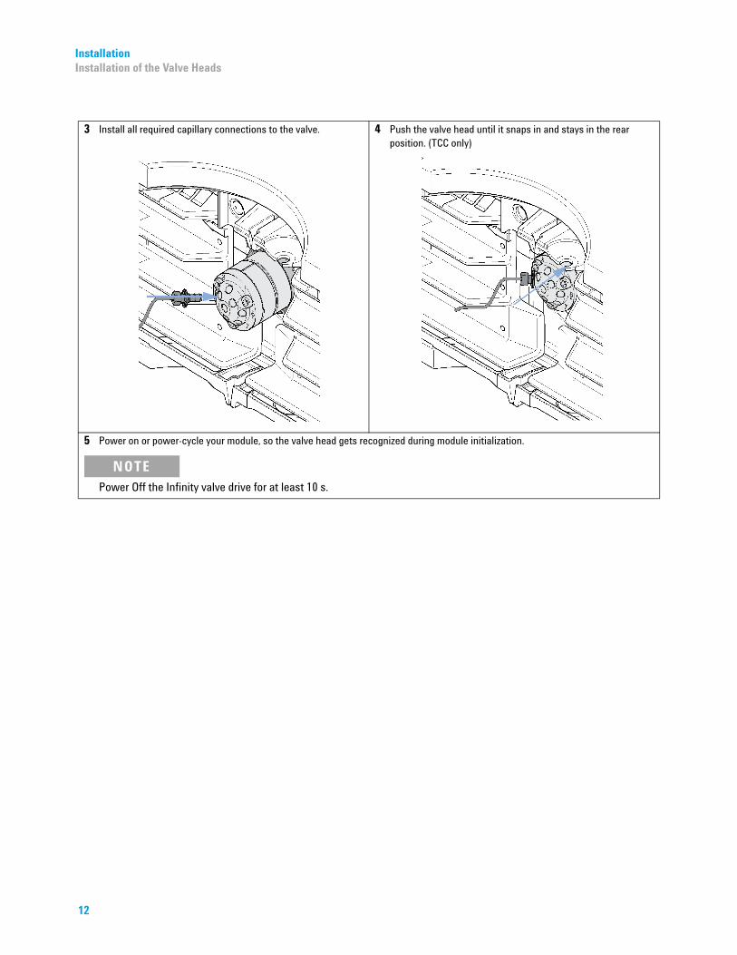
3 Install all required capillary connections to the valve. 4 Push the valve head until it snaps in and stays in the rear position. (TCC only)
5 Power on or power-cycle your module, so the valve head gets recognized during module initialization.
NOTEPower Off the Infinity valve drive for at least 10 s.
12

InstallationConnecting Valves, Heat Exchanger and Columns
Connecting Valves, Heat Exchanger and Columns
Installation of the Low Dispersion Heat-Exchanger Double Assemblies
The device is typically mounted into the center location of either the left or the right heater element where it can support two columns.
The additional heater can be arranged in the G1316C in various locations depending on the application needs. Some examples are shown in Figure 1 on page 13.
Figure 1 Arrangements of Heater and Cooling Devices (G1316C)
NOTE If the additional heater and cooling devices are used as shown in Figure 1 on page 13 (top), the column identification system cannot be used. If the column identification system is required, fix the heater and cooling devices in the upper or lower locations or fix them right/left of the current location.
NOTE The maximum flow rate to be used with the Low Dispersion Heatexchangers is 2.5 mL/min at 100 °C and 100 °C ambient.
13
Installation Connecting Valves, Heat Exchanger and Columns
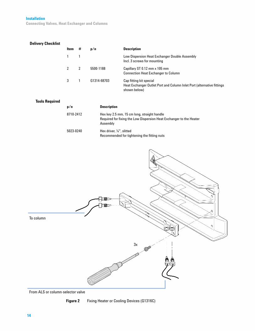
Delivery Checklist
14
Item # p/n Description
1 1 Low Dispersion Heat Exchanger Double AssemblyIncl. 3 screws for mounting
2 2 5500-1188 Capillary ST 0.12 mm x 105 mmConnection Heat Exchanger to Column
3 1 G1314-68703 Cap fitting kit specialHeat Exchanger Outlet Port and Column Inlet Port (alternative fittings shown below)
Tools Required
p/n Description8710-2412 Hex key 2.5 mm, 15 cm long, straight handleRequired for fixing the Low Dispersion Heat Exchanger to the Heater Assembly
5023-0240 Hex driver, ¼", slittedRecommended for tightening the fitting nuts
Figure 2 Fixing Heater or Cooling Devices (G1316C)
InstallationConnecting Valves, Heat Exchanger and Columns
Installing the capillaries
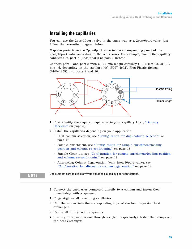
You can use the 2pos/10port valve in the same way as a 2pos/6port valve; just follow the re- routing diagram below.
Map the ports from the 2pos/6port valve to the corresponding ports of the 2pos/10port valve according to the red arrows. For example, mount the capillary connected to port 6 (2pos/6port) at port 2 instead.
Connect port 1 and port 8 with a 120 mm length capillary ( 0.12 mm i.d. or 0.17 mm i.d. depending on the capillary kit) (5067- 4652). Plug Plastic fittings (0100- 1259) into ports 9 and 10.
1 First identify the required capillaries in your capillary kits ( “Delivery Checklist” on page 5).
2 Install the capillaries depending on your application:
• Dual column selection, see “Configuration for dual- column selection” on page 17
• Sample Enrichment, see “Configuration for sample enrichment/loading position and column re- conditioning” on page 18
• Sample Clean- up, see “Configuration for sample enrichment/loading position and column re- conditioning” on page 18
• Alternating Column Regeneration (only 2pos/10port valve), see “Configuration for alternating column regeneration” on page 19
NOTE Use outmost care to avoid any void volumes caused by poor connections.
3 Connect the capillaries connected directly to a column and fasten them immediately with a spanner.
4 Finger- tighten all remaining capillaries.
5 Clip the unions into the corresponding clips of the low dispersion heat exchangers.
6 Fasten all fittings with a spanner.
7 Starting from position one through six (ten, respectively), fasten the fittings on the heat exchanger.
15
16
Installation Connecting Valves, Heat Exchanger and Columns
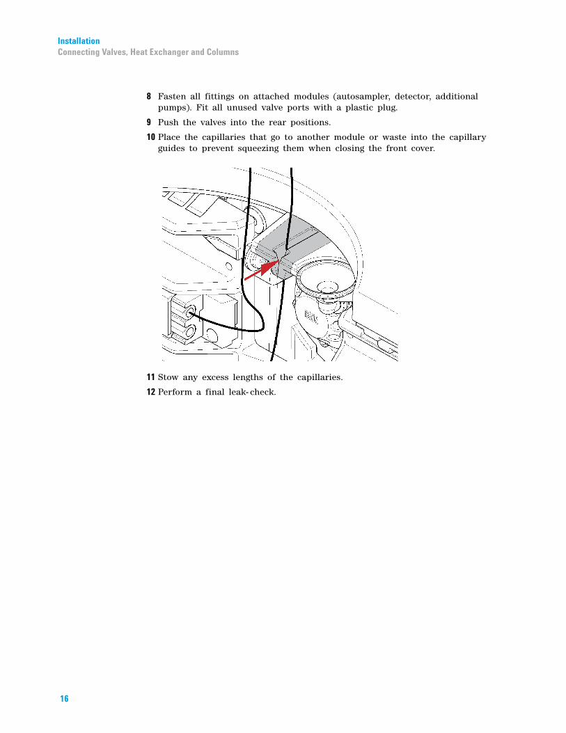
8 Fasten all fittings on attached modules (autosampler, detector, additional pumps). Fit all unused valve ports with a plastic plug.
9 Push the valves into the rear positions.
10 Place the capillaries that go to another module or waste into the capillary guides to prevent squeezing them when closing the front cover.
11 Stow any excess lengths of the capillaries.
12 Perform a final leak- check.

InstallationConnecting Valves, Heat Exchanger and Columns
Configurations and Capillary Set-up
Configuration for dual-column selection
Valve position 1-2
• Column 1 inactive• Column 2 active
Valve position 1-6
• Column 1 active• Column 2 inactive
17
18
Installation Connecting Valves, Heat Exchanger and Columns
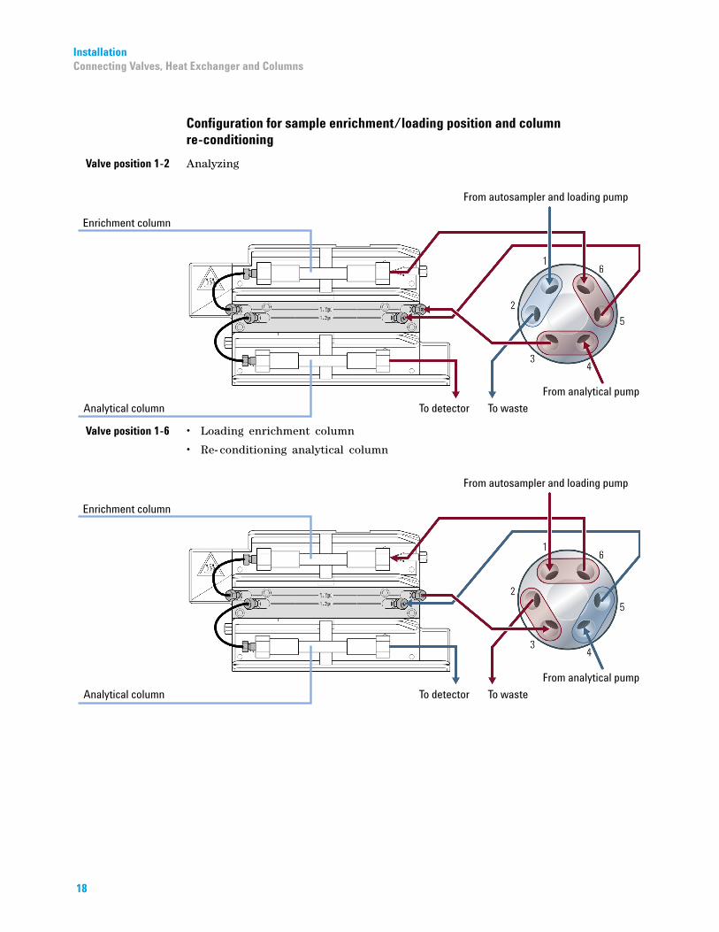
Configuration for sample enrichment/loading position and column re-conditioning
Valve position 1-2
AnalyzingValve position 1-6
• Loading enrichment column• Re- conditioning analytical column
InstallationConnecting Valves, Heat Exchanger and Columns
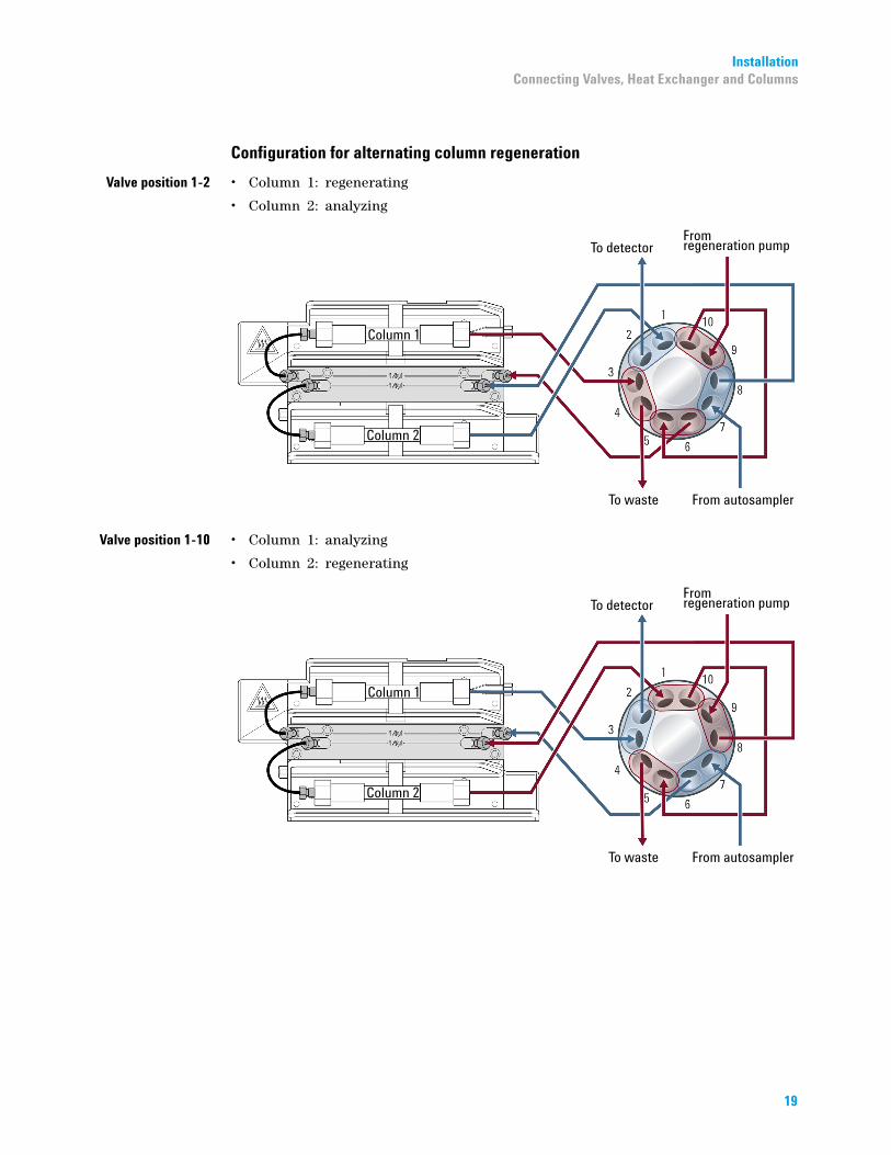
Configuration for alternating column regeneration
Valve position 1-2
• Column 1: regenerating• Column 2: analyzing
Valve position 1-10
• Column 1: analyzing• Column 2: regenerating
19

Replacement Parts Valve Head Parts
Replacement Parts
*G4232-90*G4232-90G4232-90008
nt Parts
Table 6 ReplacemeValve Rotor Seal Stator Head Bearing Ring Stator Screws(Pack of 10) Stator Ring
5067-41372 Pos/6 Port, 600 bar
0101-1409 0101-1417 1535-4045 1535-4857 5068-0120
5067-41172 Pos/6 Port, 1200 bar
5068-0008 5068-0006 1535-4045 1535-4857 5068-0120
5067-4144 2 Pos/10 Port, 600 bar micro
0101-1415 0101-1421 1535-4045 5068-0054 5068-0120
5067-41182 Pos/10 Port, 1200 bar
5068-0012 5068-0011 1534-4045 5068-0019 n.a.
5067-4145 2 Pos/10 Port, 600 bar
0101-1415 5068-0165 1535-4045 5068-0019 n.a.
Valve Head Parts
The figure below illustrates replacement parts for the valve heads, with the 12Pos/13Port SelectorFigure 3 Valve Head Parts (example)
NOTEvalve as an example. The valves can vary in their appearance and do not necessarily include all of the illustrated parts. Neither, every spare part is available for each flavor of the valve.
1 Stator screws
2 Stator head assembly
3 Stator ring screws (not available)
4 Stator ring (available for service only)
5 Rotor seal
6 Bearing ring
7 Spanner nut (available for service only)
008*008*
Part Number: G4232- 90008
Edition: 06/2015Printed in Germany
© Agilent Technologies, Inc 2015
Agilent Technologies, IncHewlett-Packard-Strasse 8
76337 WaldbronnGermany