agilent technologies n9912a fieldfox rf analyzer can connect with the agilent u2000 series usb power...
TRANSCRIPT
Agilent FieldFox RF Analyzer N9912A 4/6 GHz
Technical Overview
2
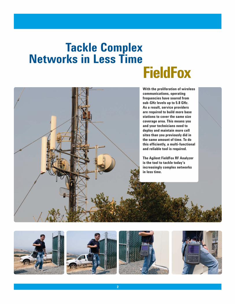
FieldFoxWith the proliferation of wireless communications, operating frequencies have soared from sub-GHz levels up to 5.8 GHz. As a result, service providers are required to build more base stations to cover the same size coverage area. This means you and your technicians need to deploy and maintain more cell sites than you previously did in the same amount of time. To do this efficiently, a multi-functional and reliable tool is required.
The Agilent FieldFox RF Analyzer is the tool to tackle today’s increasingly complex networks in less time.
Tackle Complex Networks in Less Time
2
3
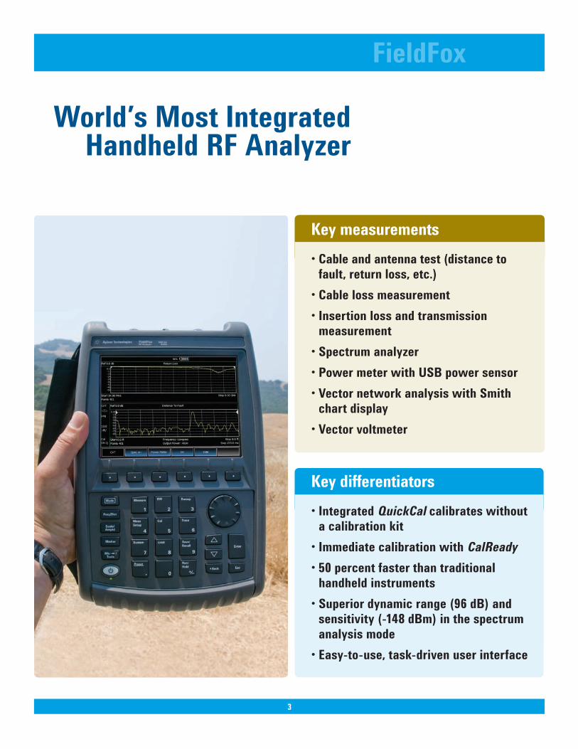
Key differentiators•IntegratedQuickCal calibrates without
a calibration kit •ImmediatecalibrationwithCalReady•50percentfasterthantraditional handheld instruments•Superiordynamicrange(96dB)andsensitivity(-148dBm)inthespectrumanalysis mode•Easy-to-use,task-drivenuserinterface
3
FieldFox
World’sMostIntegratedHandheld RF Analyzer
Key measurements•Cableandantennatest(distancetofault,returnloss,etc.)•Cablelossmeasurement•Insertionlossandtransmission measurement•Spectrumanalyzer•PowermeterwithUSBpower sensor•VectornetworkanalysiswithSmith
chart display•Vectorvoltmeter
44
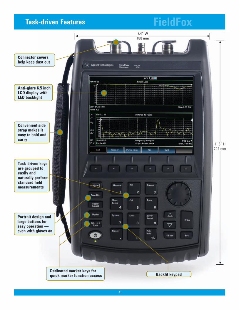
Task-driven Features FieldFox
Anti-glare 6.5 inch LCD display with LEDbacklight
BacklitkeypadDedicated marker keys for quick marker function access
11.5” H292 mm
7.4” W188 mm
Convenient sidestrap makes iteasy to hold andcarry
Connector covershelp keep dust out
Task-driven keysare grouped toeasily andnaturally performstandard fieldmeasurements
Portraitdesignandlarge buttons for easy operation — even with gloves on
55
FieldFox
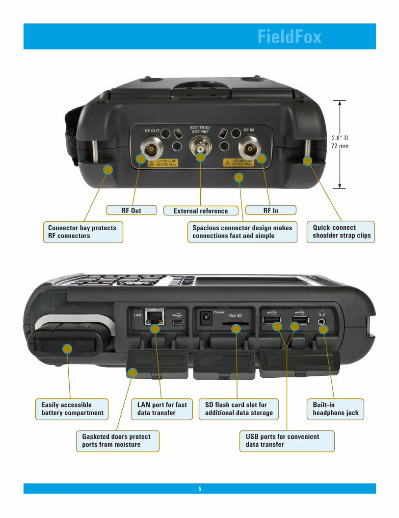
2.8” D72 mm
Externalreference
Spaciousconnectordesignmakesconnections fast and simple
Connector bay protects RF connectors
USBportsforconvenientdata transfer
Built-inheadphone jack
Easilyaccessiblebattery compartment
Gasketed doors protect ports from moisture
SDflashcardslotforadditional data storage
LAN port for fast data transfer
Quick-connectshoulder strap clips
RFInRF Out
6
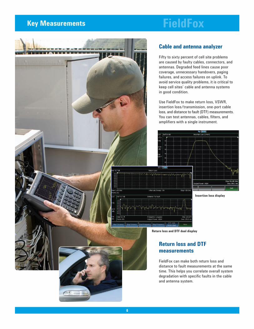
Key Measurements
Cable and antenna analyzerFifty to sixty percent of cell site problems are caused by faulty cables, connectors, and antennas. Degraded feed lines cause poor coverage, unnecessary handovers, paging failures, and access failures on uplink. To avoid service quality problems, it is critical to keep cell sites’ cable and antenna systems in good condition.
Use FieldFox to make return loss, VSWR, insertion loss/transmission, one-port cable loss, and distance to fault (DTF) measurements. You can test antennas, cables, filters, and amplifiers with a single instrument.
Return loss and DTF measurementsFieldFox can make both return loss and distance to fault measurements at the same time. This helps you correlate overall system degradation with specific faults in the cable and antenna system.
FieldFox
6
Insertionlossdisplay
Return loss and DTF dual display
7
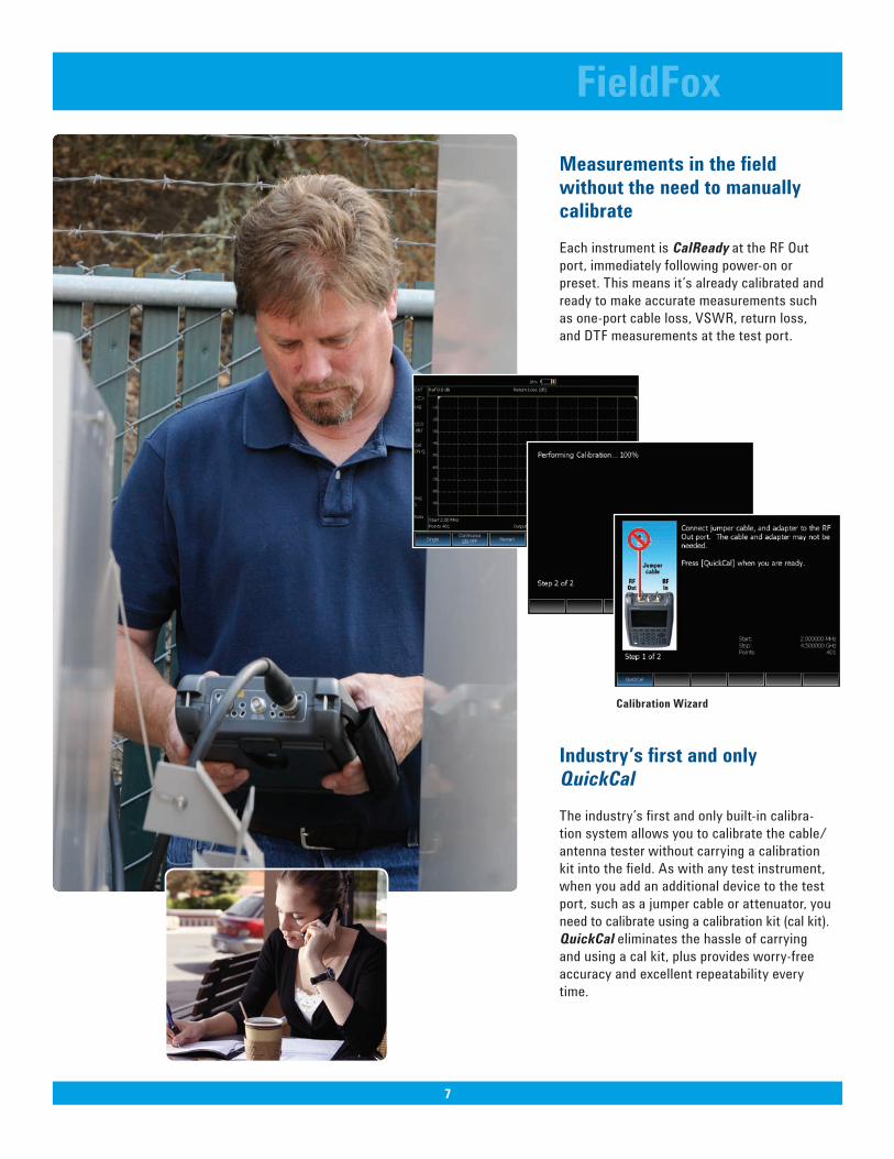
Measurements in the field without the need to manually calibrateEach instrument is CalReady at the RF Out port, immediately following power-on or preset. This means it’s already calibrated and ready to make accurate measurements such as one-port cable loss, VSWR, return loss, and DTF measurements at the test port.
Industry’sfirstandonlyQuickCalThe industry’s first and only built-in calibra-tion system allows you to calibrate the cable/antenna tester without carrying a calibration kit into the field. As with any test instrument, when you add an additional device to the test port, such as a jumper cable or attenuator, you need to calibrate using a calibration kit (cal kit). QuickCal eliminates the hassle of carrying and using a cal kit, plus provides worry-free accuracy and excellent repeatability every time.
FieldFox
7
Calibration Wizard
8
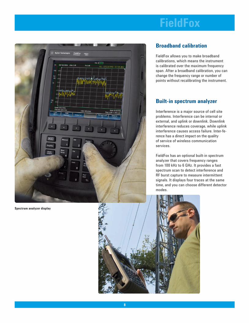
BroadbandcalibrationFieldFox allows you to make broadband calibrations, which means the instrument is calibrated over the maximum frequency span. After a broadband calibration, you can change the frequency range or number of points without recalibrating the instrument.
Built-inspectrumanalyzerInterference is a major source of cell site problems. Interference can be internal or external, and uplink or downlink. Downlink interference reduces coverage, while uplink interference causes access failure. Inter-fe-rence has a direct impact on the quality of service of wireless communication services.
FieldFox has an optional built-in spectrum analyzer that covers frequency ranges from 100 kHz to 6 GHz. It provides a fast spectrum scan to detect interference and RF burst capture to measure intermittent signals. It displays four traces at the same time, and you can choose different detector modes.
FieldFox
8
Spectrumanalyzerdisplay
9
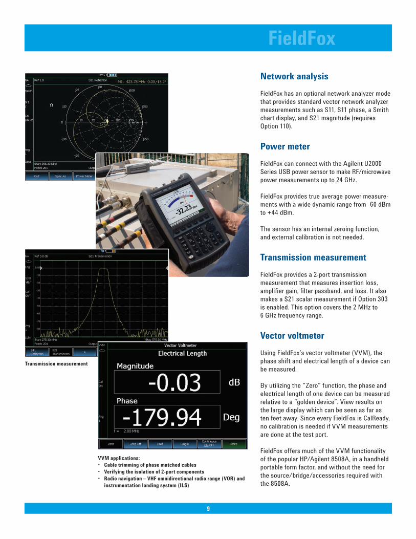
Network analysisFieldFox has an optional network analyzer mode that provides standard vector network analyzer measurements such as S11, S11 phase, a Smith chart display, and S21 magnitude (requires Option 110).
PowermeterFieldFox can connect with the Agilent U2000 Series USB power sensor to make RF/microwavepower measurements up to 24 GHz.
FieldFox provides true average power measure-ments with a wide dynamic range from -60 dBm to +44 dBm.
The sensor has an internal zeroing function, and external calibration is not needed.
Transmission measurementFieldFox provides a 2-port transmission measurement that measures insertion loss, amplifier gain, filter passband, and loss. It also makes a S21 scalar measurement if Option 303 is enabled. This option covers the 2 MHz to 6 GHz frequency range.
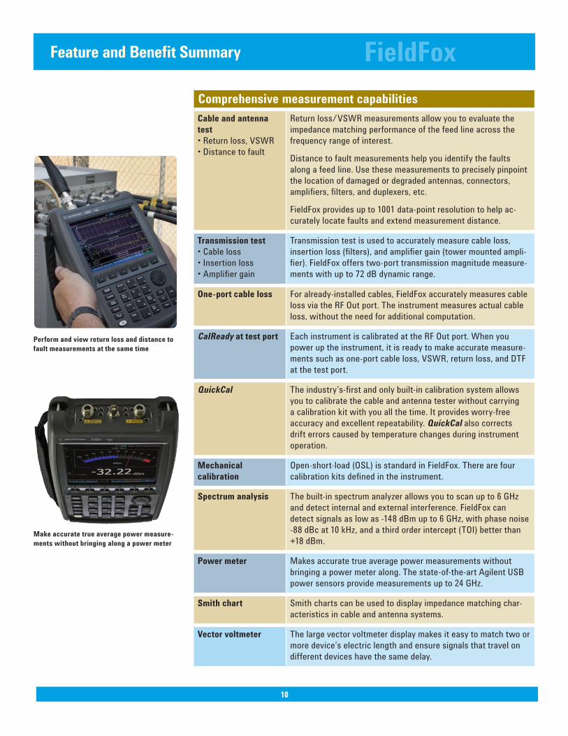
VectorvoltmeterUsing FieldFox’s vector voltmeter (VVM), the phase shift and electrical length of a device can be measured.
By utilizing the “Zero” function, the phase and electrical length of one device can be measured relative to a “golden device”. View results on the large display which can be seen as far as ten feet away. Since every FieldFox is CalReady, no calibration is needed if VVM measurements are done at the test port. FieldFox offers much of the VVM functionality of the popular HP/Agilent 8508A, in a handheld portable form factor, and without the need for the source/bridge/accessories required with the 8508A.
FieldFox
9
Transmission measurement
VVMapplications:• Cabletrimmingofphasematchedcables• Verifyingtheisolationof2-portcomponents• Radionavigation–VHFomnidirectionalradiorange(VOR)and instrumentationlandingsystem(ILS)
Comprehensive measurement capabilitiesCable and antenna test• Return loss, VSWR • Distance to fault
Return loss/VSWR measurements allow you to evaluate the impedance matching performance of the feed line across the frequency range of interest.
Distance to fault measurements help you identify the faults along a feed line. Use these measurements to precisely pinpoint the location of damaged or degraded antennas, connectors, amplifiers, filters, and duplexers, etc.
FieldFox provides up to 1001 data-point resolution to help ac-curately locate faults and extend measurement distance.
Transmission test• Cable loss • Insertion loss• Amplifier gain
Transmission test is used to accurately measure cable loss, insertion loss (filters), and amplifier gain (tower mounted ampli-fier). FieldFox offers two-port transmission magnitude measure-ments with up to 72 dB dynamic range.
One-port cable loss For already-installed cables, FieldFox accurately measures cable loss via the RF Out port. The instrument measures actual cable loss, without the need for additional computation.
CalReady at test port Each instrument is calibrated at the RF Out port. When you power up the instrument, it is ready to make accurate measure-ments such as one-port cable loss, VSWR, return loss, and DTF at the test port.
QuickCal The industry’s-first and only built-in calibration system allows you to calibrate the cable and antenna tester without carrying a calibration kit with you all the time. It provides worry-free accuracy and excellent repeatability. QuickCal also corrects drift errors caused by temperature changes during instrument operation.
Mechanical calibration
Open-short-load (OSL) is standard in FieldFox. There are four calibration kits defined in the instrument.
Spectrumanalysis The built-in spectrum analyzer allows you to scan up to 6 GHz and detect internal and external interference. FieldFox can detect signals as low as -148 dBm up to 6 GHz, with phase noise -88 dBc at 10 kHz, and a third order intercept (TOI) better than +18 dBm.
Powermeter Makes accurate true average power measurements without bringing a power meter along. The state-of-the-art Agilent USB power sensors provide measurements up to 24 GHz.
Smithchart Smith charts can be used to display impedance matching char-acteristics in cable and antenna systems.
Vectorvoltmeter The large vector voltmeter display makes it easy to match two or more device’s electric length and ensure signals that travel on different devices have the same delay.
FieldFox
10
FeatureandBenefitSummary
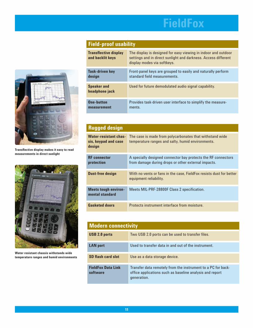
Performandviewreturnlossanddistancetofault measurements at the same time
Make accurate true average power measure-ments without bringing along a power meter
11
FieldFox
11
Field-proof usability Transflectivedisplayand backlit keys
The display is designed for easy viewing in indoor and outdoor settings and in direct sunlight and darkness. Access different display modes via softkeys.
Task-driven key design
Front-panel keys are grouped to easily and naturally perform standard field measurements.
Speakerandheadphone jack
Used for future demodulated audio signal capability.
One-button measurement
Provides task-driven user interface to simplify the measure-ments.
Modern connectivity USB2.0ports Two USB 2.0 ports can be used to transfer files.
LAN port Used to transfer data in and out of the instrument.
SDflashcardslot Use as a data storage device.
FieldFox Data Link software
Transfer data remotely from the instrument to a PC for back-office applications such as baseline analysis and report generation.
Rugged designWater-resistant chas-sis, keypad and case design
The case is made from polycarbonates that withstand wide temperature ranges and salty, humid environments.
RF connector protection
A specially designed connector bay protects the RF connectors from damage during drops or other external impacts.
Dust-free design With no vents or fans in the case, FieldFox resists dust for better equipment reliability.
Meets tough environ-mental standard
Meets MIL-PRF-28800F Class 2 specification.
Gasketed doors Protects instrument interface from moisture.
Transflectivedisplaymakesiteasytoreadmeasurements in direct sunlight
Water resistant chassis withstands wide temperature ranges and humid environments
12
FieldFoxSpecification(spec.):Warranted performance. Specifications include guardbands to account for the expected statistical performance distribution, measurement uncertainties, and changes in performance due to environmental conditions. The following conditions must be met:
• FieldFox has been turned on at least 90 minutes• FieldFox is within its calibration cycle• Storage or operation at 25 °C ±5 °C range (unless otherwise stated)
Typical(typ.):Expected performance of an average unit over a 20 °C to 30 °C temperature range, unless otherwise indicated; does not include guardbands. It is not covered by the product warranty. The FieldFox must be within its calibration cycle.
Nominal(nom.):A general, descriptive term or design parameter. It is not tested, and not covered by the product warranty.
Specifications
12
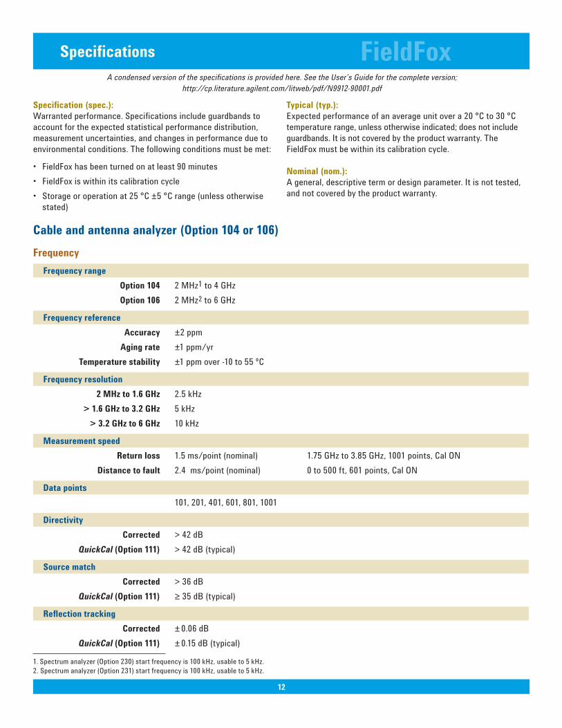
Cableandantennaanalyzer(Option104or106)Frequency Frequency range
Option104 2 MHz1 to 4 GHz Option106 2 MHz2 to 6 GHz
Frequency reference Accuracy ±2 ppm Aging rate ±1 ppm/yr Temperature stability ±1 ppm over -10 to 55 ºC Frequency resolution
2 MHz to 1.6 GHz 2.5 kHz > 1.6 GHz to 3.2 GHz 5 kHz > 3.2 GHz to 6 GHz 10 kHz
Measurement speed Return loss 1.5 ms/point (nominal) 1.75 GHz to 3.85 GHz, 1001 points, Cal ON Distance to fault 2.4 ms/point (nominal) 0 to 500 ft, 601 points, Cal ON
Data points 101, 201, 401, 601, 801, 1001
Directivity Corrected > 42 dB QuickCal(Option111) > 42 dB (typical)
Sourcematch Corrected > 36 dB QuickCal(Option111) ≥ 35 dB (typical)
Reflectiontracking Corrected ± 0.06 dB QuickCal(Option111) ± 0.15 dB (typical)
A condensed version of the specifications is provided here. See the User’s Guide for the complete version;http://cp.literature.agilent.com/litweb/pdf/N9912-90001.pdf
1. Spectrum analyzer (Option 230) start frequency is 100 kHz, usable to 5 kHz.2. Spectrum analyzer (Option 231) start frequency is 100 kHz, usable to 5 kHz.
13
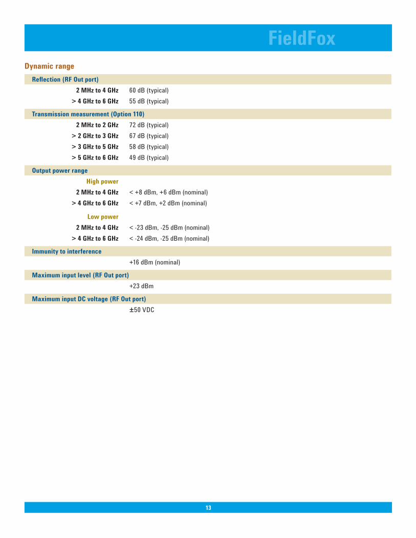
FieldFoxDynamic range Reflection(RFOutport)
2 MHz to 4 GHz 60 dB (typical) > 4 GHz to 6 GHz 55 dB (typical)
Transmissionmeasurement(Option110) 2 MHz to 2 GHz 72 dB (typical) > 2 GHz to 3 GHz 67 dB (typical) > 3 GHz to 5 GHz 58 dB (typical) > 5 GHz to 6 GHz 49 dB (typical)
Output power range High power 2 MHz to 4 GHz < +8 dBm, +6 dBm (nominal) > 4 GHz to 6 GHz < +7 dBm, +2 dBm (nominal)
Low power 2 MHz to 4 GHz < -23 dBm, -25 dBm (nominal) > 4 GHz to 6 GHz < -24 dBm, -25 dBm (nominal)
Immunitytointerference +16 dBm (nominal)
Maximuminputlevel(RFOutport) +23 dBm
Maximum input DC voltage(RFOutport) ±50 VDC
13
14
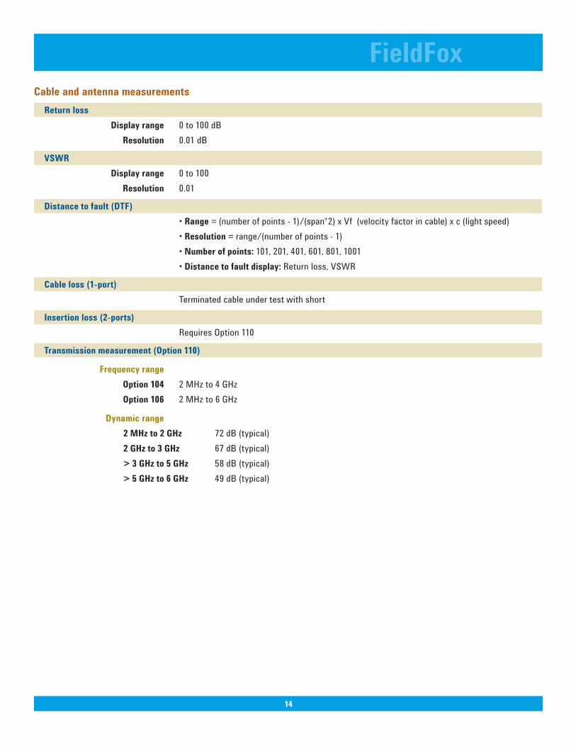
FieldFoxCable and antenna measurements Return loss
Display range 0 to 100 dB Resolution 0.01 dB
VSWR Display range 0 to 100 Resolution 0.01
Distancetofault(DTF) •Range = (number of points - 1)/(span*2) x Vf (velocity factor in cable) x c (light speed) •Resolution= range/(number of points - 1) •Numberofpoints: 101, 201, 401, 601, 801, 1001 •Distancetofaultdisplay: Return loss, VSWR
Cableloss(1-port) Terminated cable under test with short
Insertionloss(2-ports) Requires Option 110
Transmission measurement(Option110)
Frequency range Option104 2 MHz to 4 GHz Option106 2 MHz to 6 GHz
Dynamic range 2 MHz to 2 GHz 72 dB (typical) 2 GHz to 3 GHz 67 dB (typical) > 3 GHz to 5 GHz 58 dB (typical) > 5 GHz to 6 GHz 49 dB (typical)
14
15
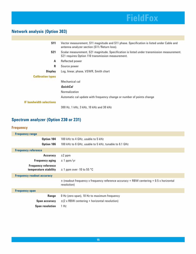
FieldFoxNetworkanalysis(Option303) S11 Vector measurement, S11 magnitude and S11 phase. Specification is listed under Cable and antenna analyzer section (S11/Return loss). S21 Scalar measurement, S21 magnitude. Specification is listed under transmission measurement. S21 requires Option 110 transmission measurement. A Reflected power R Source power Display Log, linear, phase, VSWR, Smith chart Calibration types Mechanical cal QuickCal Normalization Automatic cal update with frequency change or number of points change IFbandwidthselections 300 Hz, 1 kHz, 3 kHz, 10 kHz and 30 kHz
Spectrumanalyzer(Option230or231)Frequency Frequency range
Option104 100 kHz to 4 GHz, usable to 5 kHz Option106 100 kHz to 6 GHz, usable to 5 kHz, tunable to 6.1 GHz
Frequency reference Accuracy ±2 ppm Frequency aging ± 1 ppm/yr Frequency reference temperature stability ± 1 ppm over -10 to 55 °C
Frequency readout accuracy ± (readout frequency x frequency reference accuracy + RBW centering + 0.5 x horizontal resolution)
Frequency span Range 0 Hz (zero span), 10 Hz to maximum frequency Spanaccuracy ±(2 x RBW centering + horizontal resolution) Spanresolution 1 Hz
15
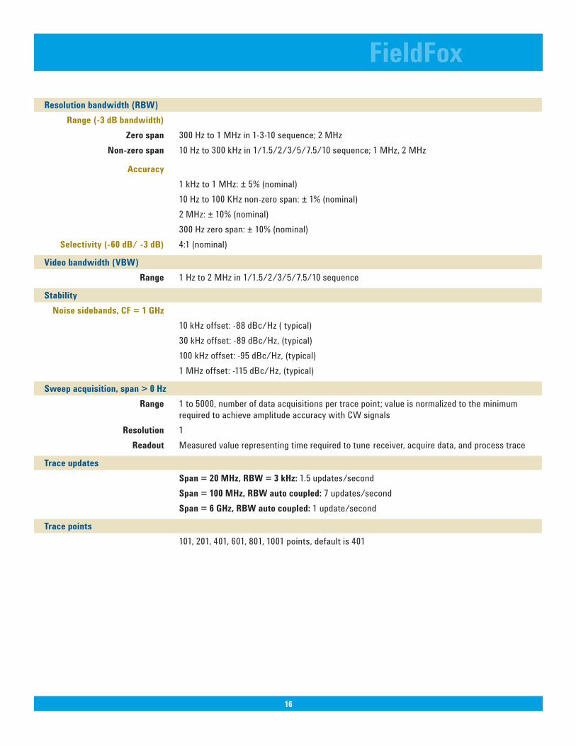
Resolutionbandwidth(RBW) Range(-3dBbandwidth) Zero span 300 Hz to 1 MHz in 1-3-10 sequence; 2 MHz Non-zero span 10 Hz to 300 kHz in 1/1.5/2/3/5/7.5/10 sequence; 1 MHz, 2 MHz Accuracy 1 kHz to 1 MHz: ± 5% (nominal) 10 Hz to 100 KHz non-zero span: ± 1% (nominal) 2 MHz: ± 10% (nominal) 300 Hz zero span: ± 10% (nominal) Selectivity(-60dB/-3dB) 4:1 (nominal)
Videobandwidth(VBW) Range 1 Hz to 2 MHz in 1/1.5/2/3/5/7.5/10 sequence
Stability Noise sidebands, CF = 1 GHz 10 kHz offset: -88 dBc/Hz ( typical) 30 kHz offset: -89 dBc/Hz, (typical) 100 kHz offset: -95 dBc/Hz, (typical) 1 MHz offset: -115 dBc/Hz, (typical)
Sweepacquisition,span>0Hz Range 1 to 5000, number of data acquisitions per trace point; value is normalized to the minimum required to achieve amplitude accuracy with CW signals Resolution 1 Readout Measured value representing time required to tune receiver, acquire data, and process trace
Trace updates Span=20MHz,RBW=3kHz: 1.5 updates/second Span=100MHz,RBWautocoupled:7 updates/second Span=6GHz,RBWautocoupled: 1 update/second
Trace points 101, 201, 401, 601, 801, 1001 points, default is 401
FieldFox
16
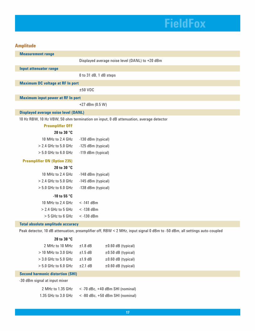
Amplitude Measurement range
Displayed average noise level (DANL) to +20 dBm
Inputattenuatorrange 0 to 31 dB, 1 dB steps
MaximumDCvoltageatRFInport ±50 VDC
MaximuminputpoweratRFInport +27 dBm (0.5 W)
Displayedaveragenoiselevel(DANL) 10 Hz RBW, 10 Hz VBW, 50 ohm termination on input, 0 dB attenuation, average detector PreamplifierOFF 20to30°C 10 MHz to 2.4 GHz -130 dBm (typical) > 2.4 GHz to 5.0 GHz -125 dBm (typical) > 5.0 GHz to 6.0 GHz -119 dBm (typical)
PreamplifierON(Option235) 20to30°C 10 MHz to 2.4 GHz -148 dBm (typical) > 2.4 GHz to 5.0 GHz -145 dBm (typical) > 5.0 GHz to 6.0 GHz -138 dBm (typical)
-10to55°C 10 MHz to 2.4 GHz < -141 dBm > 2.4 GHz to 5 GHz < -138 dBm > 5 GHz to 6 GHz < -130 dBm
Total absolute amplitude accuracy Peak detector, 10 dB attenuation, preamplifier off, RBW < 2 MHz, input signal 0 dBm to -50 dBm, all settings auto-coupled
20to30ºC 2 MHz to 10 MHz ±1.8 dB ±0.60 dB (typical) > 10 MHz to 3.0 GHz ±1.5 dB ±0.50 dB (typical) > 3.0 GHz to 5.0 GHz ±1.9 dB ±0.60 dB (typical) > 5.0 GHz to 6.0 GHz ±2.1 dB ±0.60 dB (typical)
Secondharmonicdistortion(SHI) -30 dBm signal at input mixer
2 MHz to 1.35 GHz < -70 dBc, +40 dBm SHI (nominal) 1.35 GHz to 3.0 GHz < -80 dBc, +50 dBm SHI (nominal)
FieldFox
17
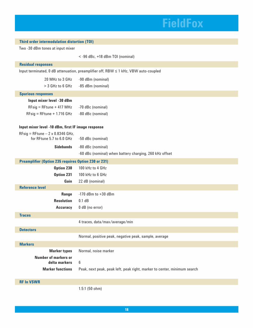
Thirdorderintermodulationdistortion(TOI) Two -30 dBm tones at input mixer
< -96 dBc, +18 dBm TOI (nominal)
Residual responses Input terminated, 0 dB attenuation, preamplifier off, RBW ≤ 1 kHz, VBW auto-coupled
20 MHz to 3 GHz -90 dBm (nominal) > 3 GHz to 6 GHz -85 dBm (nominal)
Spuriousresponses Inputmixerlevel-30dBm RFsig = RFtune + 417 MHz -70 dBc (nominal) RFsig = RFtune + 1.716 GHz -80 dBc (nominal) Inputmixerlevel-10dBm,firstIFimageresponse RFsig = RFtune – 2 x 0.8346 GHz, for RFtune 5.7 to 6.0 GHz -50 dBc (nominal) Sidebands -80 dBc (nominal) -60 dBc (nominal) when battery charging, 260 kHz offset Preamplifier(Option235requiresOption230or231)
Option230 100 kHz to 4 GHz Option 231 100 kHz to 6 GHz Gain 22 dB (nominal) Reference level
Range -170 dBm to +30 dBm Resolution 0.1 dB Accuracy 0 dB (no error)
Traces 4 traces, data/max/average/min
Detectors Normal, positive peak, negative peak, sample, average
Markers Marker types Normal, noise marker Number of markers or delta markers 6 Marker functions Peak, next peak, peak left, peak right, marker to center, minimum search RFInVSWR
1.5:1 (50 ohm)
FieldFox
18
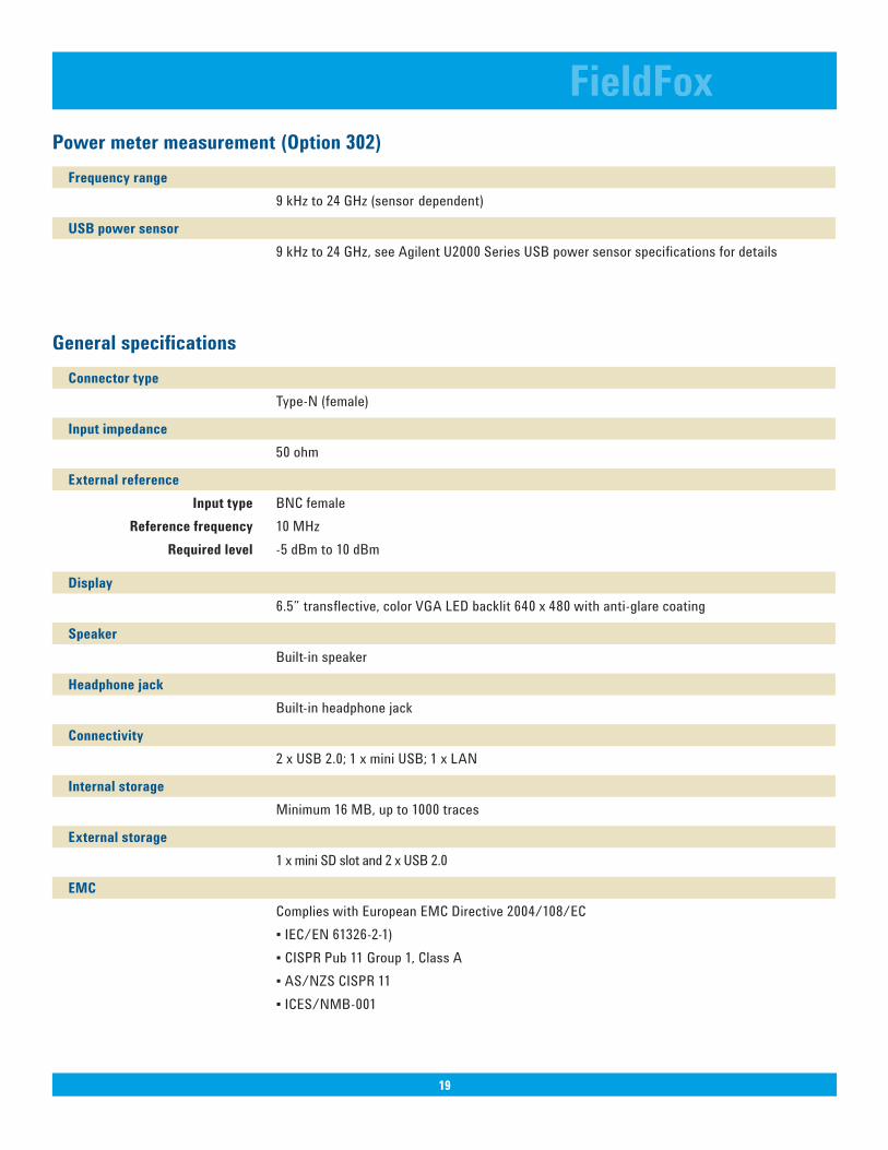
Powermetermeasurement(Option302) Frequency range
9 kHz to 24 GHz (sensor dependent)
USBpowersensor 9 kHz to 24 GHz, see Agilent U2000 Series USB power sensor specifications for details
General specifications Connector type
Type-N (female)
Inputimpedance 50 ohm
Externalreference Inputtype BNC female Reference frequency 10 MHz Required level -5 dBm to 10 dBm
Display 6.5” transflective, color VGA LED backlit 640 x 480 with anti-glare coating
Speaker Built-in speaker
Headphone jack Built-in headphone jack
Connectivity 2 x USB 2.0; 1 x mini USB; 1 x LAN
Internalstorage Minimum 16 MB, up to 1000 traces
Externalstorage 1 x mini SD slot and 2 x USB 2.0
EMC Complies with European EMC Directive 2004/108/EC ▪ IEC/EN 61326-2-1) ▪ CISPR Pub 11 Group 1, Class A ▪ AS/NZS CISPR 11 ▪ ICES/NMB-001
FieldFox
19
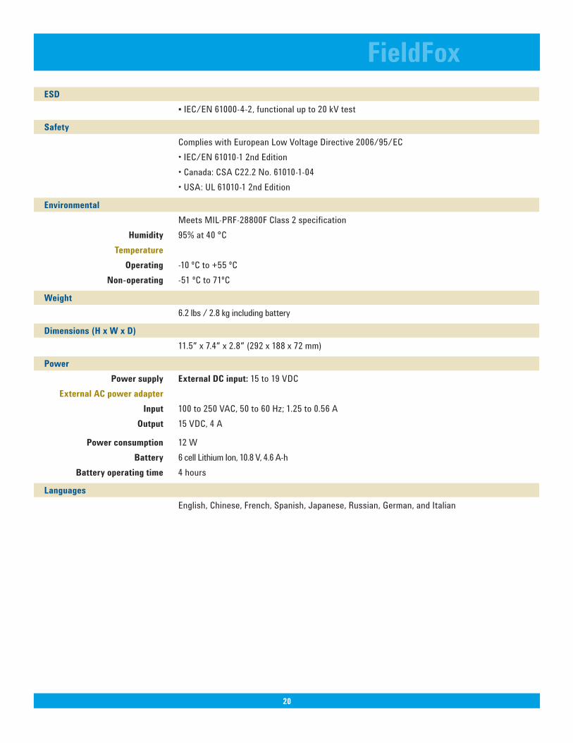
ESD ▪ IEC/EN 61000-4-2, functional up to 20 kV test
Safety Complies with European Low Voltage Directive 2006/95/EC • IEC/EN 61010-1 2nd Edition • Canada: CSA C22.2 No. 61010-1-04 • USA: UL 61010-1 2nd Edition
Environmental Meets MIL-PRF-28800F Class 2 specification Humidity 95% at 40 °C Temperature Operating -10 ºC to +55 ºC Non-operating -51 ºC to 71ºC
Weight 6.2 lbs / 2.8 kg including battery
Dimensions(HxWxD) 11.5″ x 7.4″ x 2.8″ (292 x 188 x 72 mm)
Power Powersupply ExternalDCinput:15 to 19 VDC ExternalACpoweradapter Input 100 to 250 VAC, 50 to 60 Hz; 1.25 to 0.56 A Output 15 VDC, 4 A
Powerconsumption 12 W Battery 6 cell Lithium Ion, 10.8 V, 4.6 A-h Batteryoperatingtime 4 hours
Languages English, Chinese, French, Spanish, Japanese, Russian, German, and Italian
FieldFox
20
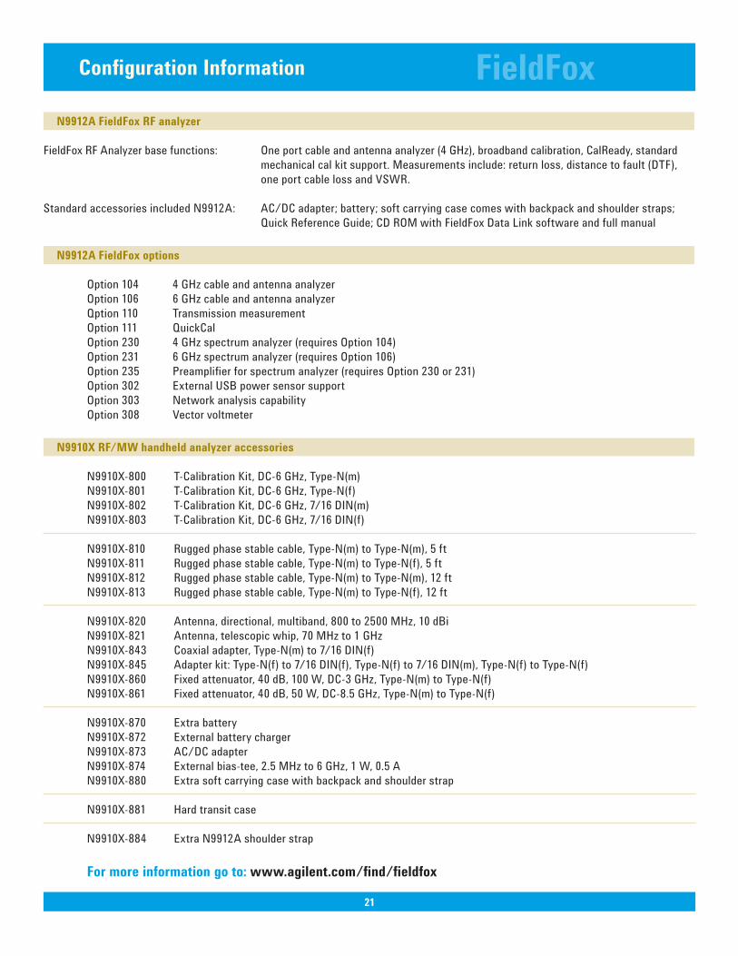
N9912A FieldFox RF analyzer
FieldFox RF Analyzer base functions: One port cable and antenna analyzer (4 GHz), broadband calibration, CalReady, standard mechanical cal kit support. Measurements include: return loss, distance to fault (DTF), one port cable loss and VSWR.
Standard accessories included N9912A: AC/DC adapter; battery; soft carrying case comes with backpack and shoulder straps; Quick Reference Guide; CD ROM with FieldFox Data Link software and full manual
N9912A FieldFox options
Option 104 4 GHz cable and antenna analyzer Option 106 6 GHz cable and antenna analyzer Qption 110 Transmission measurement Option 111 QuickCal Option 230 4 GHz spectrum analyzer (requires Option 104) Option 231 6 GHz spectrum analyzer (requires Option 106) Option 235 Preamplifier for spectrum analyzer (requires Option 230 or 231) Option 302 External USB power sensor support Option 303 Network analysis capability Option 308 Vector voltmeter
N9910XRF/MWhandheldanalyzeraccessories
N9910X-800 T-Calibration Kit, DC-6 GHz, Type-N(m) N9910X-801 T-Calibration Kit, DC-6 GHz, Type-N(f) N9910X-802 T-Calibration Kit, DC-6 GHz, 7/16 DIN(m) N9910X-803 T-Calibration Kit, DC-6 GHz, 7/16 DIN(f) N9910X-810 Rugged phase stable cable, Type-N(m) to Type-N(m), 5 ft N9910X-811 Rugged phase stable cable, Type-N(m) to Type-N(f), 5 ft N9910X-812 Rugged phase stable cable, Type-N(m) to Type-N(m), 12 ft N9910X-813 Rugged phase stable cable, Type-N(m) to Type-N(f), 12 ft N9910X-820 Antenna, directional, multiband, 800 to 2500 MHz, 10 dBi N9910X-821 Antenna, telescopic whip, 70 MHz to 1 GHz N9910X-843 Coaxial adapter, Type-N(m) to 7/16 DIN(f) N9910X-845 Adapter kit: Type-N(f) to 7/16 DIN(f), Type-N(f) to 7/16 DIN(m), Type-N(f) to Type-N(f) N9910X-860 Fixed attenuator, 40 dB, 100 W, DC-3 GHz, Type-N(m) to Type-N(f) N9910X-861 Fixed attenuator, 40 dB, 50 W, DC-8.5 GHz, Type-N(m) to Type-N(f) N9910X-870 Extra battery N9910X-872 External battery charger N9910X-873 AC/DC adapter N9910X-874 External bias-tee, 2.5 MHz to 6 GHz, 1 W, 0.5 A N9910X-880 Extra soft carrying case with backpack and shoulder strap N9910X-881 Hard transit case N9910X-884 Extra N9912A shoulder strap
Formoreinformationgoto:www.agilent.com/find/fieldfox
FieldFox
21
ConfigurationInformation
FieldFox
22
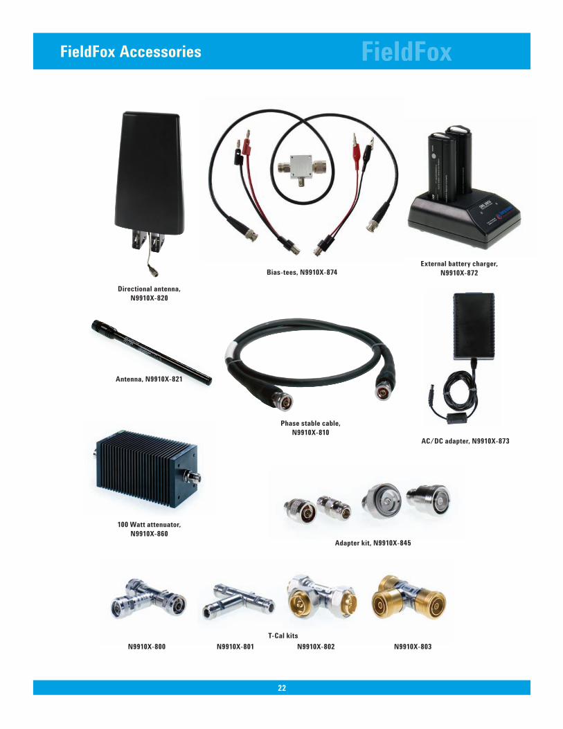
FieldFox Accessories
T-Cal kits
Phasestablecable,N9910X-810
Antenna,N9910X-821
Directional antenna, N9910X-820
100Wattattenuator,N9910X-860
Bias-tees,N9910X-874
Adapterkit,N9910X-845
Externalbatterycharger,N9910X-872
AC/DCadapter,N9910X-873
N9910X-800 N9910X-803N9910X-801 N9910X-802
FieldFox
23
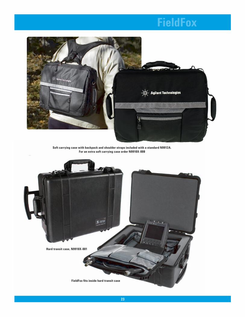
SoftcarryingcasewithbackpackandshoulderstrapsincludedwithastandardN9912A.ForanextrasoftcarryingcaseorderN9910X-880
FieldFox fits inside hard transit case
Hardtransitcase,N9910X-881
Product specifications and descriptions in this document subject to change without notice.
© Agilent Technologies, Inc. 2008, 2009Printed in USA, February 2, 20095989-8618EN