agilent technologies 10gbase-kr/40gbase-kr4 ......agilent technologies 10gbase-kr/40gbase-kr4...
TRANSCRIPT
Agilent Technologies
10GBASE-KR/40GBASE-KR4
Backplane Ethernet
Interconnect &
Transmitter/Receiver (Tx/Rx)
Tests
Test Solution Overview Using
the Agilent E5071C ENA
Option TDR
Last Update 2014/04/21
Purpose
2
• This slide will show how to make measurements of 10GBASE-
KR/40GBASE-KR4 Backplane Ethernet Interconnect &
Transmitter/Receiver (Tx/Rx) Tests by using the Agilent E5071C ENA
Option TDR.
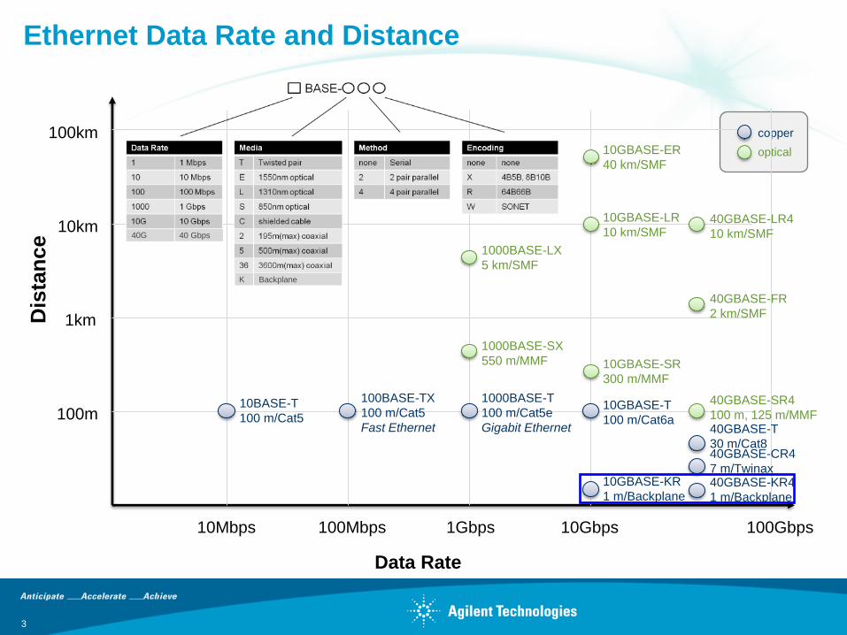
Ethernet Data Rate and Distance
3
10Mbps 100Mbps 1Gbps 10Gbps
10BASE-T
100 m/Cat5
100BASE-TX
100 m/Cat5
Fast Ethernet
1000BASE-T
100 m/Cat5e
Gigabit Ethernet
1000BASE-SX
550 m/MMF
1000BASE-LX
5 km/SMF
10GBASE-SR
300 m/MMF
10GBASE-LR
10 km/SMF
10GBASE-ER
40 km/SMF
10km
100km
1km
100m
Data Rate
Dis
tan
ce
copper
optical
10GBASE-T
100 m/Cat6a
10GBASE-KR
1 m/Backplane
40GBASE-T
30 m/Cat8
100Gbps
40GBASE-KR4
1 m/Backplane
40GBASE-SR4
100 m, 125 m/MMF
40GBASE-CR4
7 m/Twinax
40GBASE-FR
2 km/SMF
40GBASE-LR4
10 km/SMF
Backplane K
40 Gbps 40G
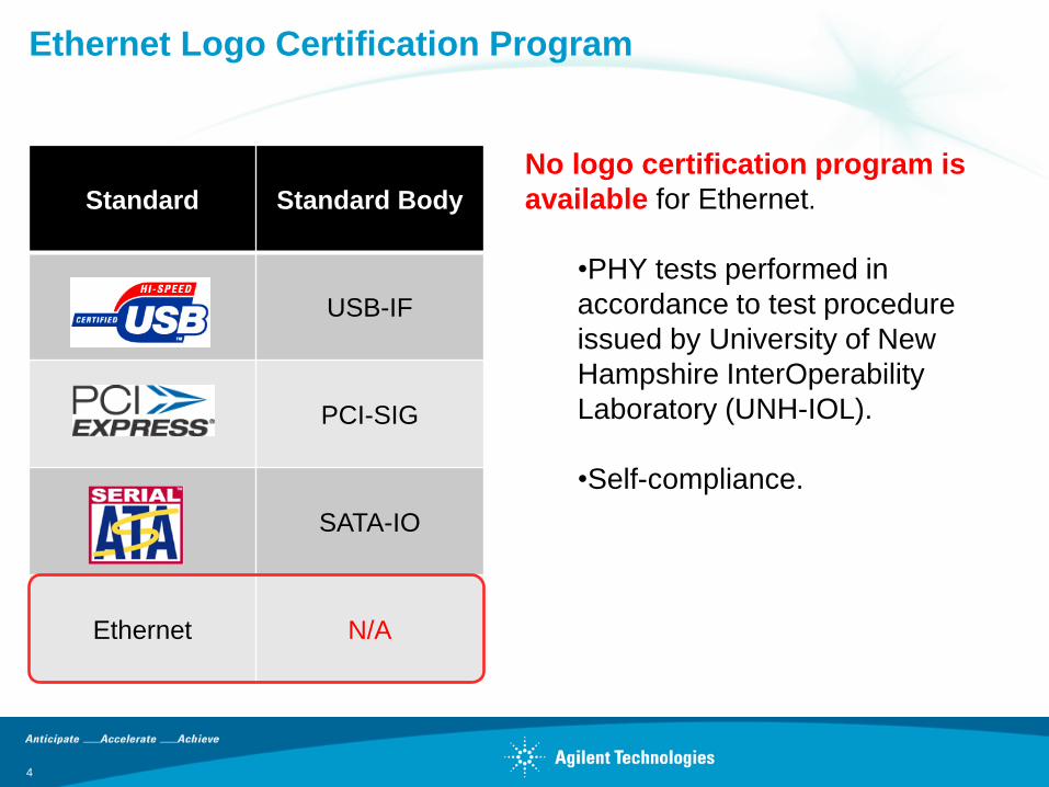
Standard Standard Body
USB-IF
PCI-SIG
SATA-IO
Ethernet N/A
No logo certification program is
available for Ethernet.
•PHY tests performed in
accordance to test procedure
issued by University of New
Hampshire InterOperability
Laboratory (UNH-IOL).
•Self-compliance.
Ethernet Logo Certification Program
4
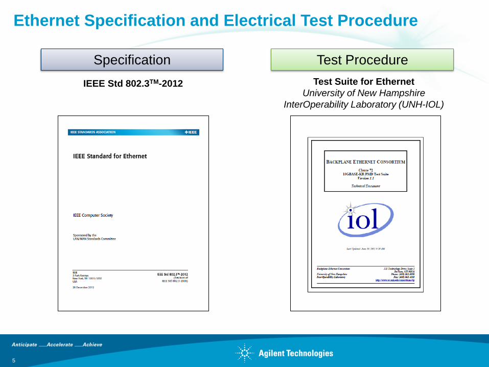
IEEE Std 802.3TM-2012 Test Suite for Ethernet
University of New Hampshire
InterOperability Laboratory (UNH-IOL)
Specification Test Procedure
Ethernet Specification and Electrical Test Procedure
5
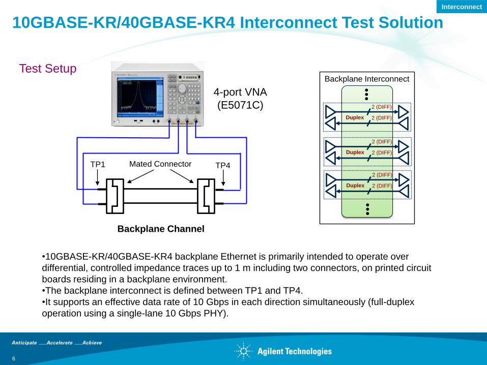
10GBASE-KR/40GBASE-KR4 Interconnect Test Solution
6
•10GBASE-KR/40GBASE-KR4 backplane Ethernet is primarily intended to operate over
differential, controlled impedance traces up to 1 m including two connectors, on printed circuit
boards residing in a backplane environment.
•The backplane interconnect is defined between TP1 and TP4.
•It supports an effective data rate of 10 Gbps in each direction simultaneously (full-duplex
operation using a single-lane 10 Gbps PHY).
Test Setup
4-port VNA
(E5071C)
TP1
Backplane Channel
TP4 Mated Connector
Backplane Interconnect
•••
•••
Duplex
2 (DIFF)
2 (DIFF)
Duplex
2 (DIFF)
2 (DIFF)
Duplex
2 (DIFF)
2 (DIFF)
Interconnect
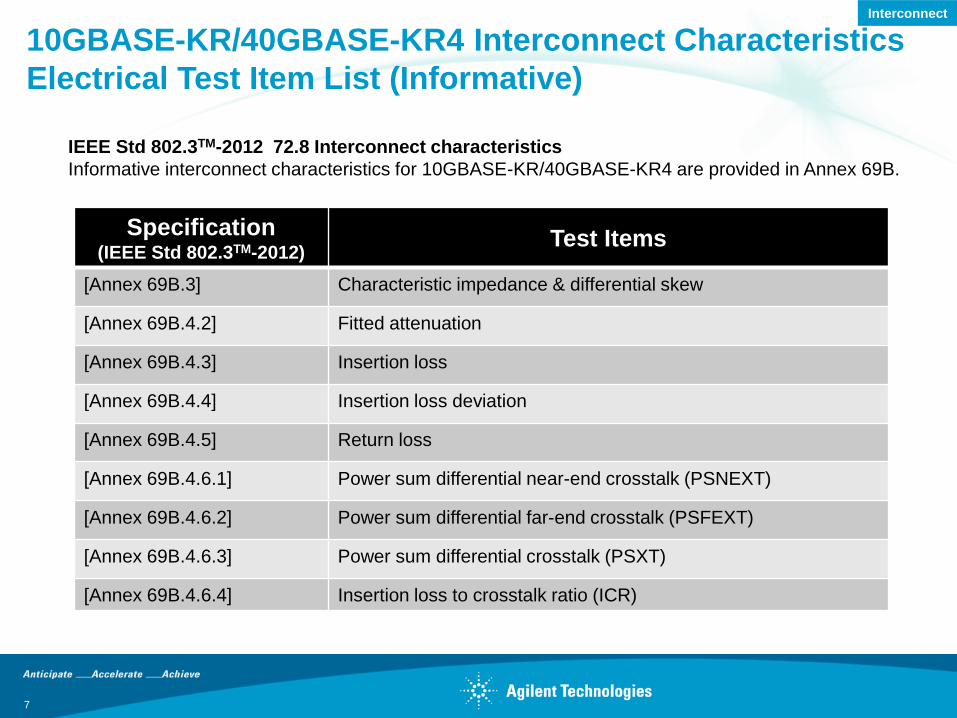
10GBASE-KR/40GBASE-KR4 Interconnect Characteristics
Electrical Test Item List (Informative)
Specification (IEEE Std 802.3TM-2012)
Test Items
[Annex 69B.3] Characteristic impedance & differential skew
[Annex 69B.4.2] Fitted attenuation
[Annex 69B.4.3] Insertion loss
[Annex 69B.4.4] Insertion loss deviation
[Annex 69B.4.5] Return loss
[Annex 69B.4.6.1] Power sum differential near-end crosstalk (PSNEXT)
[Annex 69B.4.6.2] Power sum differential far-end crosstalk (PSFEXT)
[Annex 69B.4.6.3] Power sum differential crosstalk (PSXT)
[Annex 69B.4.6.4] Insertion loss to crosstalk ratio (ICR)
7
IEEE Std 802.3TM-2012 72.8 Interconnect characteristics
Informative interconnect characteristics for 10GBASE-KR/40GBASE-KR4 are provided in Annex 69B.
Interconnect
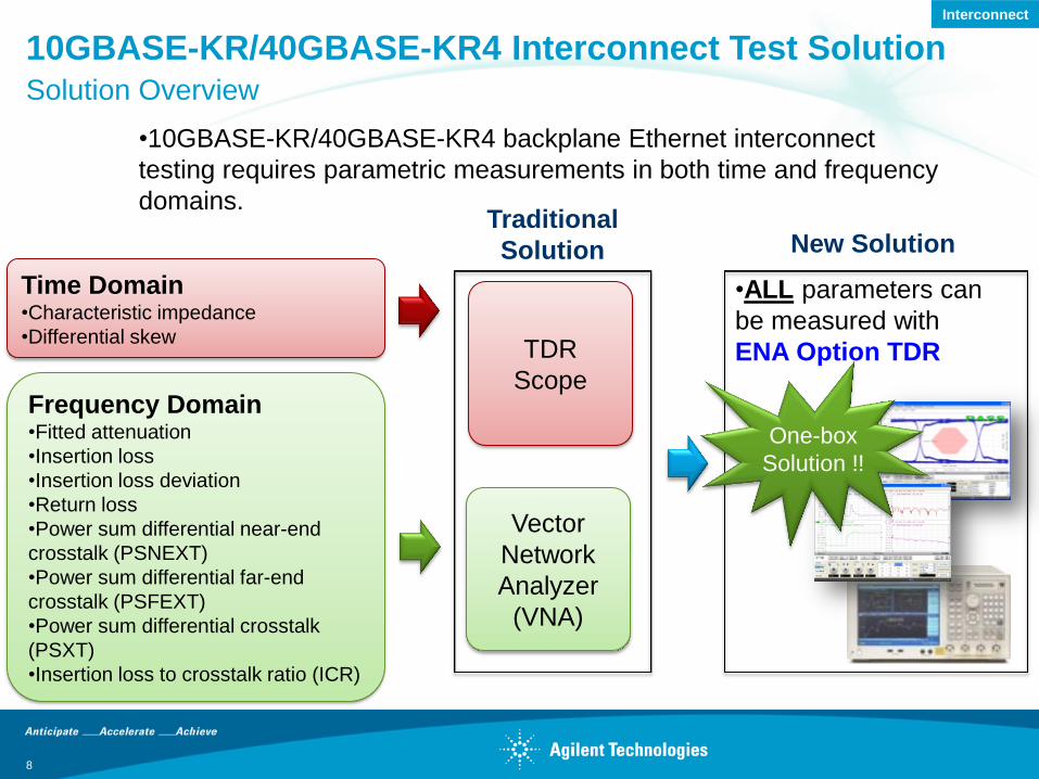
•10GBASE-KR/40GBASE-KR4 backplane Ethernet interconnect
testing requires parametric measurements in both time and frequency
domains.
Frequency Domain •Fitted attenuation
•Insertion loss
•Insertion loss deviation
•Return loss
•Power sum differential near-end
crosstalk (PSNEXT)
•Power sum differential far-end
crosstalk (PSFEXT)
•Power sum differential crosstalk
(PSXT)
•Insertion loss to crosstalk ratio (ICR)
Time Domain •Characteristic impedance
•Differential skew
Traditional
Solution New Solution
10GBASE-KR/40GBASE-KR4 Interconnect Test Solution Solution Overview
Vector
Network
Analyzer
(VNA)
TDR
Scope
•ALL parameters can
be measured with
ENA Option TDR
One-box
Solution !!
8
Interconnect
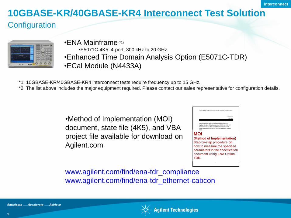
•Method of Implementation (MOI)
document, state file (4K5), and VBA
project file available for download on
Agilent.com
MOI (Method of Implementation)
Step-by-step procedure on
how to measure the specified
parameters in the specification
document using ENA Option
TDR.
•ENA Mainframe (*1)
•E5071C-4K5: 4-port, 300 kHz to 20 GHz
•Enhanced Time Domain Analysis Option (E5071C-TDR)
•ECal Module (N4433A)
www.agilent.com/find/ena-tdr_compliance
www.agilent.com/find/ena-tdr_ethernet-cabcon
10GBASE-KR/40GBASE-KR4 Interconnect Test Solution Configuration
*1: 10GBASE-KR/40GBASE-KR4 interconnect tests require frequency up to 15 GHz.
*2: The list above includes the major equipment required. Please contact our sales representative for configuration details.
9
Interconnect
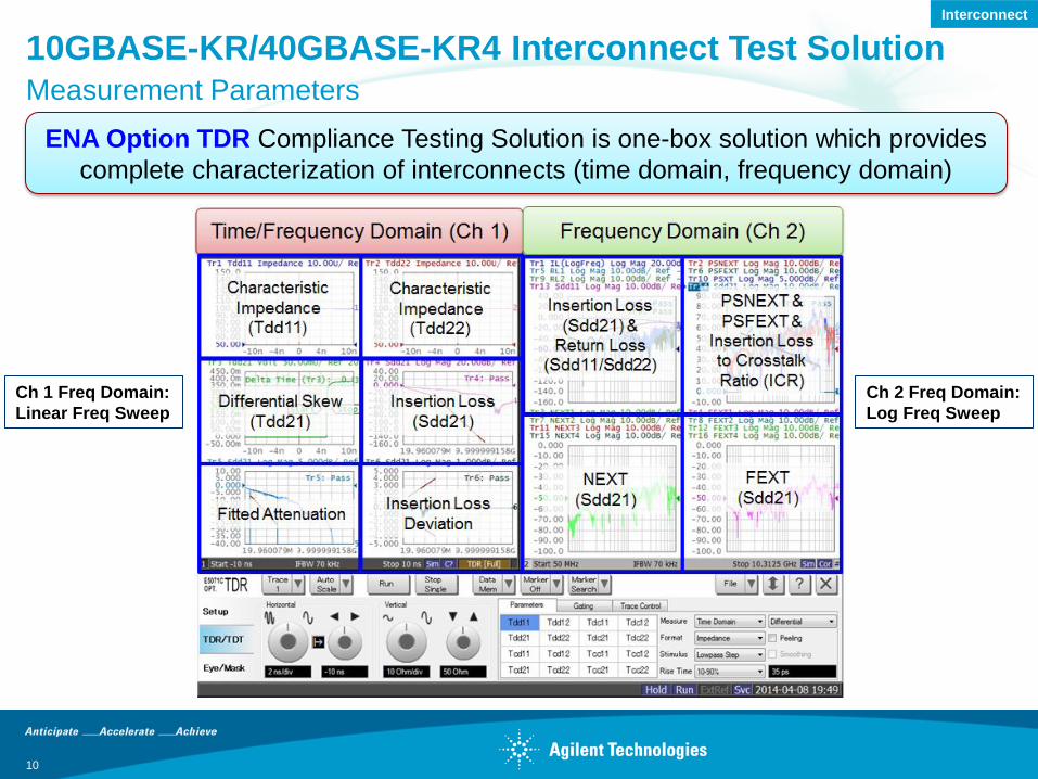
10GBASE-KR/40GBASE-KR4 Interconnect Test Solution Measurement Parameters
ENA Option TDR Compliance Testing Solution is one-box solution which provides
complete characterization of interconnects (time domain, frequency domain)
10
Ch 1 Freq Domain:
Linear Freq Sweep
Ch 2 Freq Domain:
Log Freq Sweep
Interconnect
Backplane Interconnect
•••
•••
Duplex
2 (DIFF)
2 (DIFF)
Duplex
2 (DIFF)
2 (DIFF)
Duplex
2 (DIFF)
2 (DIFF)
11
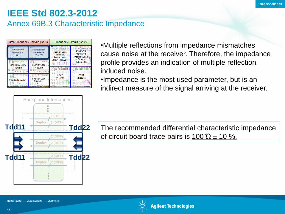
IEEE Std 802.3-2012 Annex 69B.3 Characteristic Impedance
•Multiple reflections from impedance mismatches
cause noise at the receiver. Therefore, the impedance
profile provides an indication of multiple reflection
induced noise.
•Impedance is the most used parameter, but is an
indirect measure of the signal arriving at the receiver.
The recommended differential characteristic impedance
of circuit board trace pairs is 100 Ώ ± 10 %.
Tdd11 Tdd22
Tdd11 Tdd22
Interconnect
Backplane Interconnect
•••
•••
Duplex
2 (DIFF)
2 (DIFF)
Duplex
2 (DIFF)
2 (DIFF)
Duplex
2 (DIFF)
2 (DIFF)
12
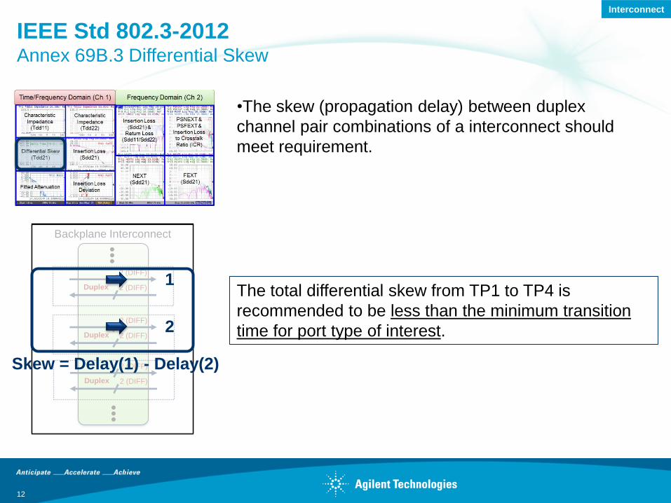
IEEE Std 802.3-2012 Annex 69B.3 Differential Skew
The total differential skew from TP1 to TP4 is
recommended to be less than the minimum transition
time for port type of interest.
•The skew (propagation delay) between duplex
channel pair combinations of a interconnect should
meet requirement.
Skew = Delay(1) - Delay(2)
1
2
Interconnect
13
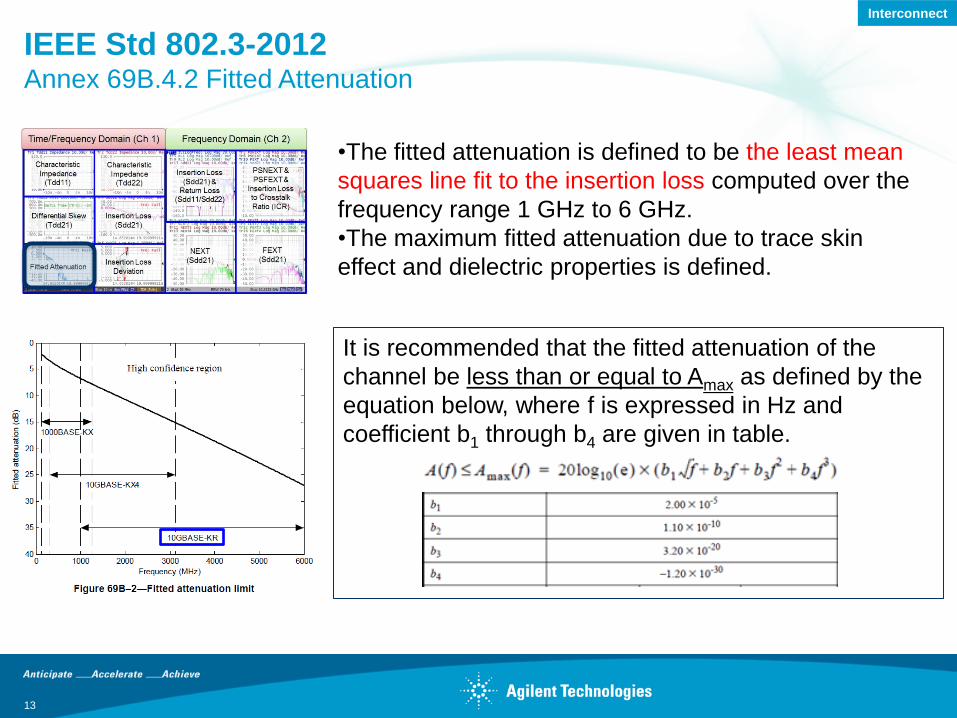
IEEE Std 802.3-2012 Annex 69B.4.2 Fitted Attenuation
It is recommended that the fitted attenuation of the
channel be less than or equal to Amax as defined by the
equation below, where f is expressed in Hz and
coefficient b1 through b4 are given in table.
•The fitted attenuation is defined to be the least mean
squares line fit to the insertion loss computed over the
frequency range 1 GHz to 6 GHz.
•The maximum fitted attenuation due to trace skin
effect and dielectric properties is defined.
Interconnect
Backplane Interconnect
•••
•••
Duplex
2 (DIFF)
2 (DIFF)
Duplex
2 (DIFF)
2 (DIFF)
Duplex
2 (DIFF)
2 (DIFF)
14
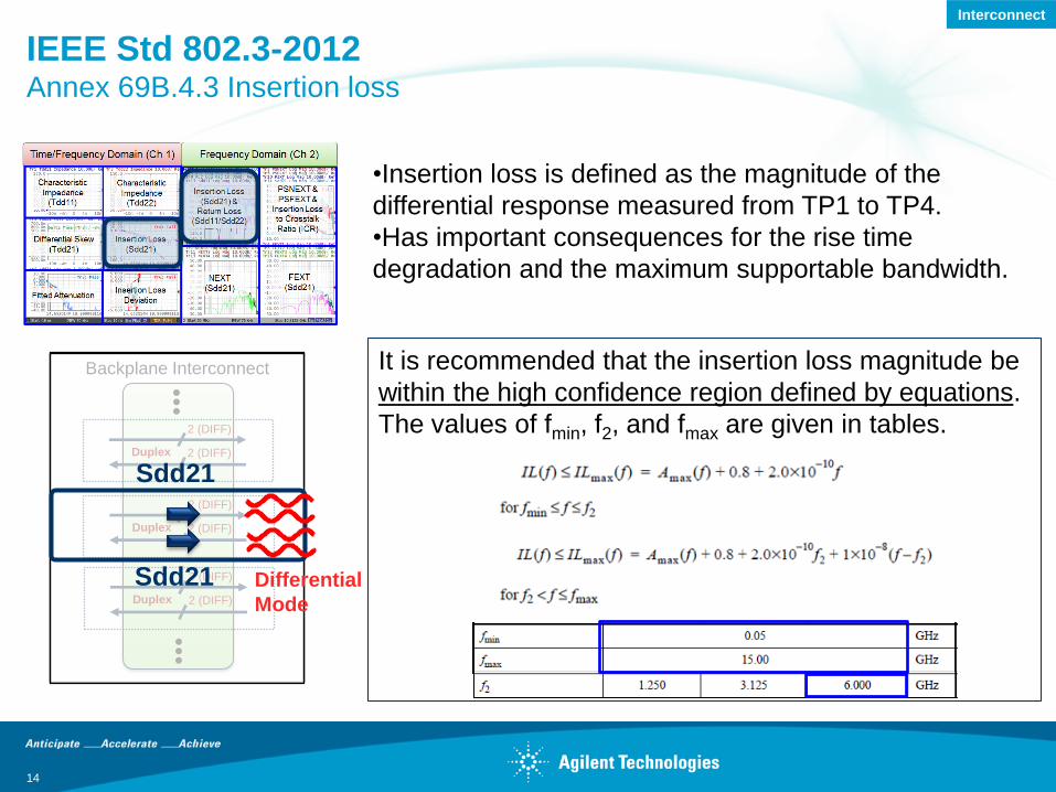
IEEE Std 802.3-2012 Annex 69B.4.3 Insertion loss
•Insertion loss is defined as the magnitude of the
differential response measured from TP1 to TP4.
•Has important consequences for the rise time
degradation and the maximum supportable bandwidth.
Sdd21 Differential
Mode
It is recommended that the insertion loss magnitude be
within the high confidence region defined by equations.
The values of fmin, f2, and fmax are given in tables.
Sdd21
Interconnect
15
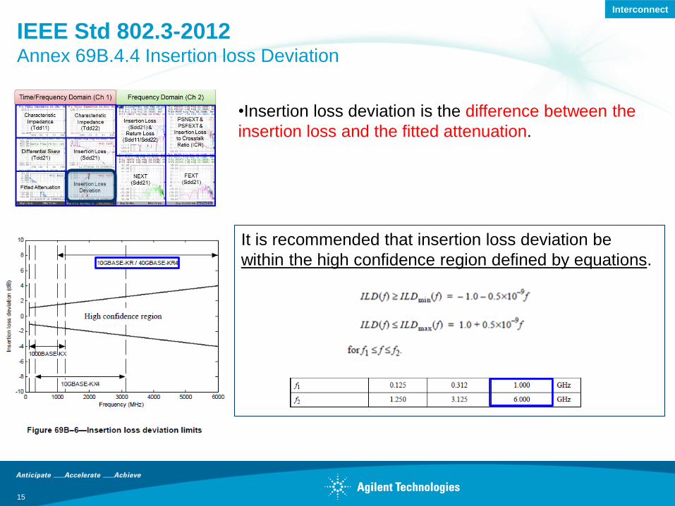
IEEE Std 802.3-2012 Annex 69B.4.4 Insertion loss Deviation
•Insertion loss deviation is the difference between the
insertion loss and the fitted attenuation.
It is recommended that insertion loss deviation be
within the high confidence region defined by equations.
Interconnect
Backplane Interconnect
•••
•••
Duplex
2 (DIFF)
2 (DIFF)
Duplex
2 (DIFF)
2 (DIFF)
Duplex
2 (DIFF)
2 (DIFF)
16
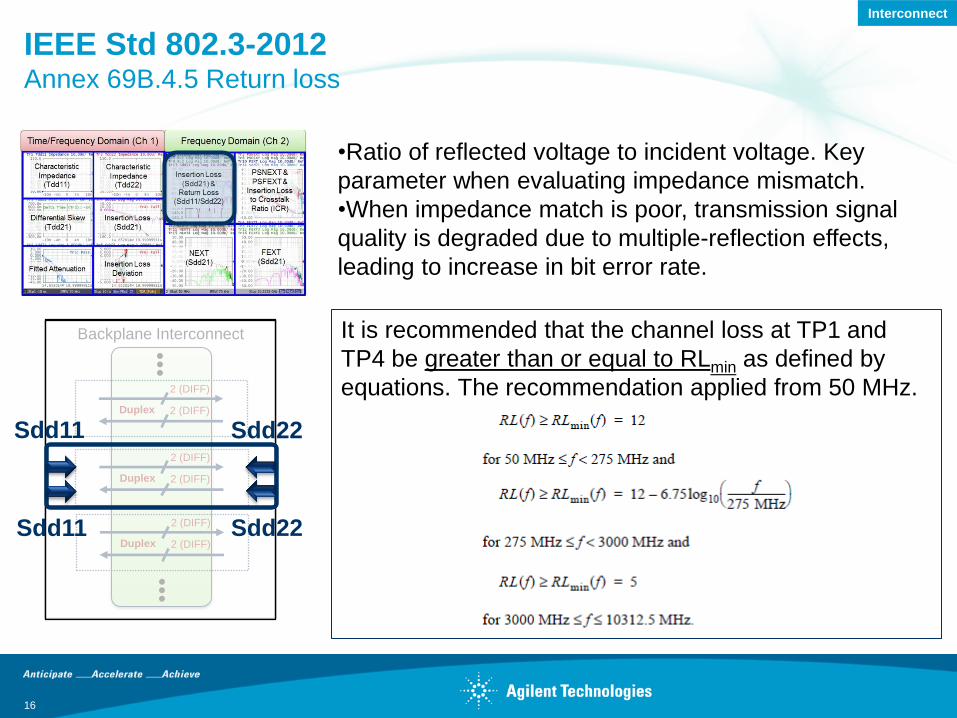
IEEE Std 802.3-2012 Annex 69B.4.5 Return loss
•Ratio of reflected voltage to incident voltage. Key
parameter when evaluating impedance mismatch.
•When impedance match is poor, transmission signal
quality is degraded due to multiple-reflection effects,
leading to increase in bit error rate.
Sdd11 Sdd22
It is recommended that the channel loss at TP1 and
TP4 be greater than or equal to RLmin as defined by
equations. The recommendation applied from 50 MHz.
Sdd11 Sdd22
Interconnect
Backplane Interconnect
•••
•••
Duplex
2 (DIFF)
2 (DIFF)
Duplex
2 (DIFF)
2 (DIFF)
Duplex
2 (DIFF)
2 (DIFF)
17
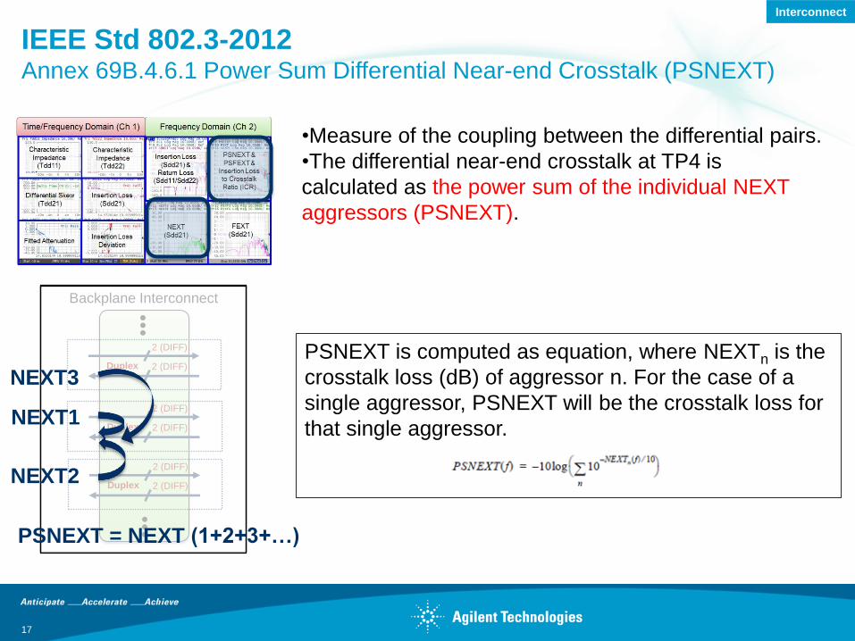
IEEE Std 802.3-2012 Annex 69B.4.6.1 Power Sum Differential Near-end Crosstalk (PSNEXT)
•Measure of the coupling between the differential pairs.
•The differential near-end crosstalk at TP4 is
calculated as the power sum of the individual NEXT
aggressors (PSNEXT).
NEXT1
NEXT2
PSNEXT is computed as equation, where NEXTn is the
crosstalk loss (dB) of aggressor n. For the case of a
single aggressor, PSNEXT will be the crosstalk loss for
that single aggressor.
PSNEXT = NEXT (1+2+3+…)
NEXT3
Interconnect
Backplane Interconnect
•••
•••
Duplex
2 (DIFF)
2 (DIFF)
Duplex
2 (DIFF)
2 (DIFF)
Duplex
2 (DIFF)
2 (DIFF)
PSFEXT = FEXT (1+2+3+…)
18
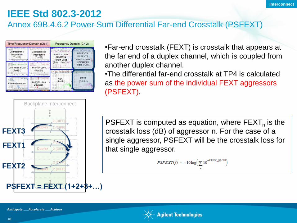
IEEE Std 802.3-2012 Annex 69B.4.6.2 Power Sum Differential Far-end Crosstalk (PSFEXT)
•Far-end crosstalk (FEXT) is crosstalk that appears at
the far end of a duplex channel, which is coupled from
another duplex channel.
•The differential far-end crosstalk at TP4 is calculated
as the power sum of the individual FEXT aggressors
(PSFEXT).
FEXT1
FEXT2
PSFEXT is computed as equation, where FEXTn is the
crosstalk loss (dB) of aggressor n. For the case of a
single aggressor, PSFEXT will be the crosstalk loss for
that single aggressor.
FEXT3
Interconnect
Backplane Interconnect
•••
•••
Duplex
2 (DIFF)
2 (DIFF)
Duplex
2 (DIFF)
2 (DIFF)
Duplex
2 (DIFF)
2 (DIFF)
19
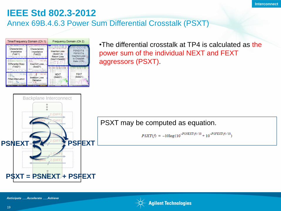
IEEE Std 802.3-2012 Annex 69B.4.6.3 Power Sum Differential Crosstalk (PSXT)
•The differential crosstalk at TP4 is calculated as the
power sum of the individual NEXT and FEXT
aggressors (PSXT).
PSXT = PSNEXT + PSFEXT
PSFEXT PSNEXT
PSXT may be computed as equation.
Interconnect
20
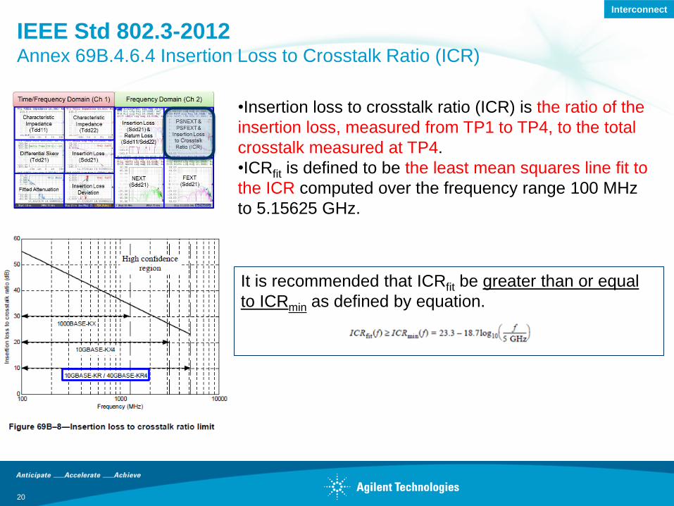
IEEE Std 802.3-2012 Annex 69B.4.6.4 Insertion Loss to Crosstalk Ratio (ICR)
•Insertion loss to crosstalk ratio (ICR) is the ratio of the
insertion loss, measured from TP1 to TP4, to the total
crosstalk measured at TP4.
•ICRfit is defined to be the least mean squares line fit to
the ICR computed over the frequency range 100 MHz
to 5.15625 GHz.
It is recommended that ICRfit be greater than or equal
to ICRmin as defined by equation.
Interconnect
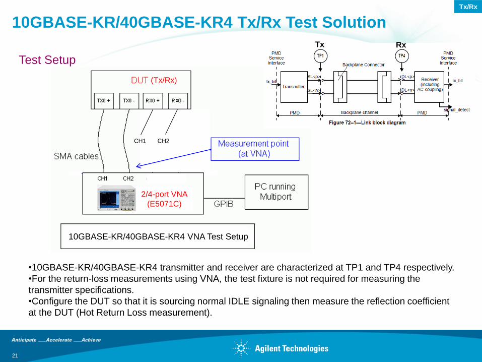
10GBASE-KR/40GBASE-KR4 Tx/Rx Test Solution
21
•10GBASE-KR/40GBASE-KR4 transmitter and receiver are characterized at TP1 and TP4 respectively.
•For the return-loss measurements using VNA, the test fixture is not required for measuring the
transmitter specifications.
•Configure the DUT so that it is sourcing normal IDLE signaling then measure the reflection coefficient
at the DUT (Hot Return Loss measurement).
Test Setup
2/4-port VNA
(E5071C)
(Tx/Rx)
Tx Rx
CH1 CH2
Tx/Rx
10GBASE-KR/40GBASE-KR4 VNA Test Setup
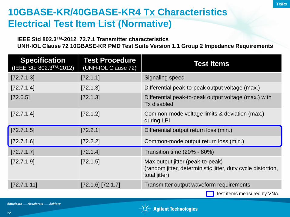
10GBASE-KR/40GBASE-KR4 Tx Characteristics
Electrical Test Item List (Normative)
Specification (IEEE Std 802.3TM-2012)
Test Procedure (UNH-IOL Clause 72)
Test Items
[72.7.1.3] [72.1.1] Signaling speed
[72.7.1.4] [72.1.3] Differential peak-to-peak output voltage (max.)
[72.6.5] [72.1.3] Differential peak-to-peak output voltage (max.) with
Tx disabled
[72.7.1.4] [72.1.2] Common-mode voltage limits & deviation (max.)
during LPI
[72.7.1.5] [72.2.1] Differential output return loss (min.)
[72.7.1.6] [72.2.2] Common-mode output return loss (min.)
[72.7.1.7] [72.1.4] Transition time (20% - 80%)
[72.7.1.9] [72.1.5] Max output jitter (peak-to-peak)
(random jitter, deterministic jitter, duty cycle distortion,
total jitter)
[72.7.1.11] [72.1.6] [72.1.7] Transmitter output waveform requirements
22
IEEE Std 802.3TM-2012 72.7.1 Transmitter characteristics
UNH-IOL Clause 72 10GBASE-KR PMD Test Suite Version 1.1 Group 2 Impedance Requirements
Test items measured by VNA
Tx/Rx
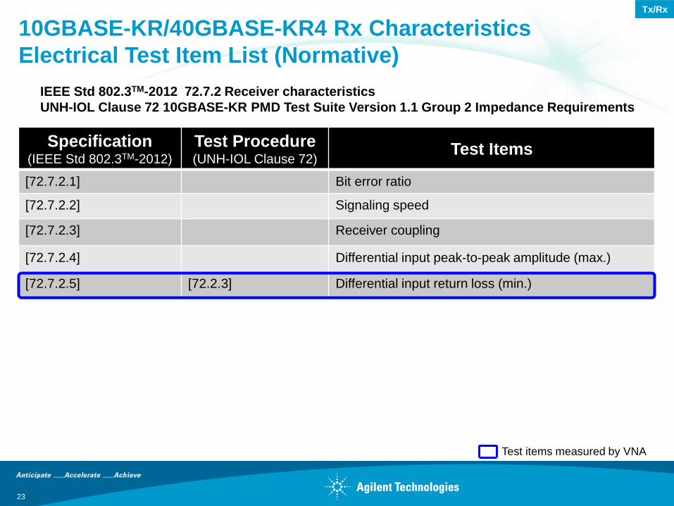
10GBASE-KR/40GBASE-KR4 Rx Characteristics
Electrical Test Item List (Normative)
Specification (IEEE Std 802.3TM-2012)
Test Procedure (UNH-IOL Clause 72)
Test Items
[72.7.2.1] Bit error ratio
[72.7.2.2] Signaling speed
[72.7.2.3] Receiver coupling
[72.7.2.4] Differential input peak-to-peak amplitude (max.)
[72.7.2.5] [72.2.3] Differential input return loss (min.)
23
IEEE Std 802.3TM-2012 72.7.2 Receiver characteristics
UNH-IOL Clause 72 10GBASE-KR PMD Test Suite Version 1.1 Group 2 Impedance Requirements
Test items measured by VNA
Tx/Rx
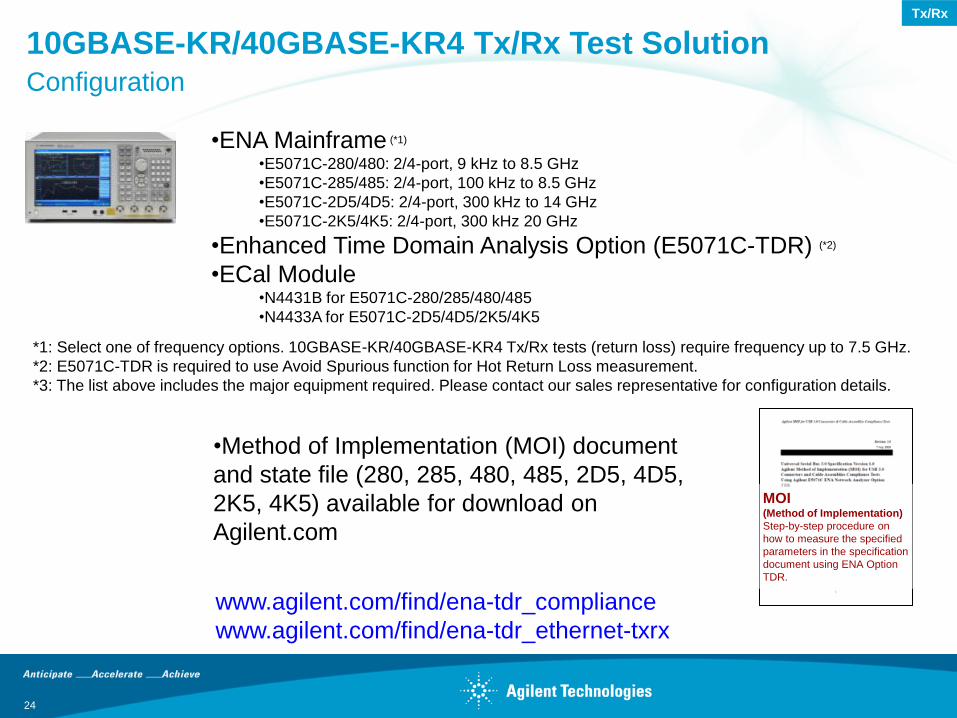
•Method of Implementation (MOI) document
and state file (280, 285, 480, 485, 2D5, 4D5,
2K5, 4K5) available for download on
Agilent.com
MOI (Method of Implementation)
Step-by-step procedure on
how to measure the specified
parameters in the specification
document using ENA Option
TDR.
•ENA Mainframe (*1)
•E5071C-280/480: 2/4-port, 9 kHz to 8.5 GHz
•E5071C-285/485: 2/4-port, 100 kHz to 8.5 GHz
•E5071C-2D5/4D5: 2/4-port, 300 kHz to 14 GHz
•E5071C-2K5/4K5: 2/4-port, 300 kHz 20 GHz
•Enhanced Time Domain Analysis Option (E5071C-TDR) (*2)
•ECal Module •N4431B for E5071C-280/285/480/485
•N4433A for E5071C-2D5/4D5/2K5/4K5
www.agilent.com/find/ena-tdr_compliance
www.agilent.com/find/ena-tdr_ethernet-txrx
10GBASE-KR/40GBASE-KR4 Tx/Rx Test Solution Configuration
*1: Select one of frequency options. 10GBASE-KR/40GBASE-KR4 Tx/Rx tests (return loss) require frequency up to 7.5 GHz.
*2: E5071C-TDR is required to use Avoid Spurious function for Hot Return Loss measurement.
*3: The list above includes the major equipment required. Please contact our sales representative for configuration details.
24
Tx/Rx
10GBASE-KR/40GBASE-KR4 Tx/Rx Test Solution Measurement Parameters
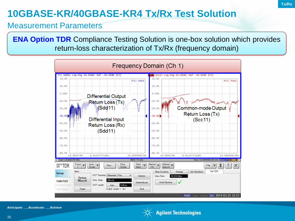
ENA Option TDR Compliance Testing Solution is one-box solution which provides
return-loss characterization of Tx/Rx (frequency domain)
25
Tx/Rx
26
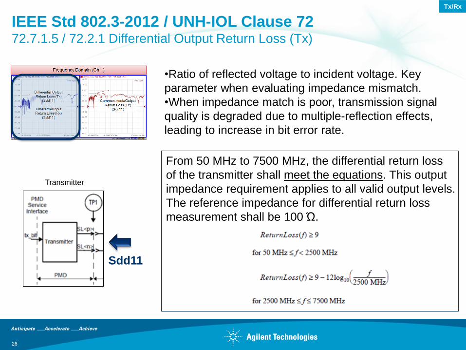
IEEE Std 802.3-2012 / UNH-IOL Clause 72 72.7.1.5 / 72.2.1 Differential Output Return Loss (Tx)
•Ratio of reflected voltage to incident voltage. Key
parameter when evaluating impedance mismatch.
•When impedance match is poor, transmission signal
quality is degraded due to multiple-reflection effects,
leading to increase in bit error rate.
Sdd11
From 50 MHz to 7500 MHz, the differential return loss
of the transmitter shall meet the equations. This output
impedance requirement applies to all valid output levels.
The reference impedance for differential return loss
measurement shall be 100 Ώ.
Transmitter
Tx/Rx
27
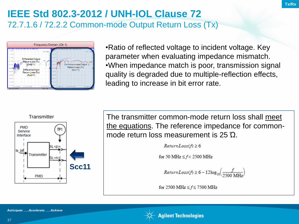
IEEE Std 802.3-2012 / UNH-IOL Clause 72 72.7.1.6 / 72.2.2 Common-mode Output Return Loss (Tx)
•Ratio of reflected voltage to incident voltage. Key
parameter when evaluating impedance mismatch.
•When impedance match is poor, transmission signal
quality is degraded due to multiple-reflection effects,
leading to increase in bit error rate.
Scc11
The transmitter common-mode return loss shall meet
the equations. The reference impedance for common-
mode return loss measurement is 25 Ώ.
Transmitter
Tx/Rx
28
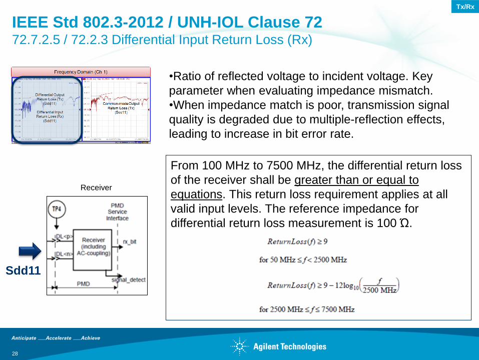
IEEE Std 802.3-2012 / UNH-IOL Clause 72 72.7.2.5 / 72.2.3 Differential Input Return Loss (Rx)
•Ratio of reflected voltage to incident voltage. Key
parameter when evaluating impedance mismatch.
•When impedance match is poor, transmission signal
quality is degraded due to multiple-reflection effects,
leading to increase in bit error rate.
Sdd11
From 100 MHz to 7500 MHz, the differential return loss
of the receiver shall be greater than or equal to
equations. This return loss requirement applies at all
valid input levels. The reference impedance for
differential return loss measurement is 100 Ώ.
Receiver
Tx/Rx
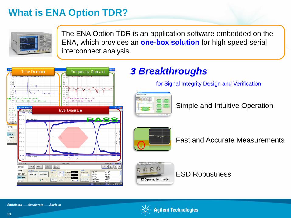
The ENA Option TDR is an application software embedded on the
ENA, which provides an one-box solution for high speed serial
interconnect analysis.
What is ENA Option TDR?
29
Frequency Domain Time Domain 3 Breakthroughs for Signal Integrity Design and Verification
Eye Diagram
ESD protection inside
Simple and Intuitive Operation
ESD Robustness
Fast and Accurate Measurements
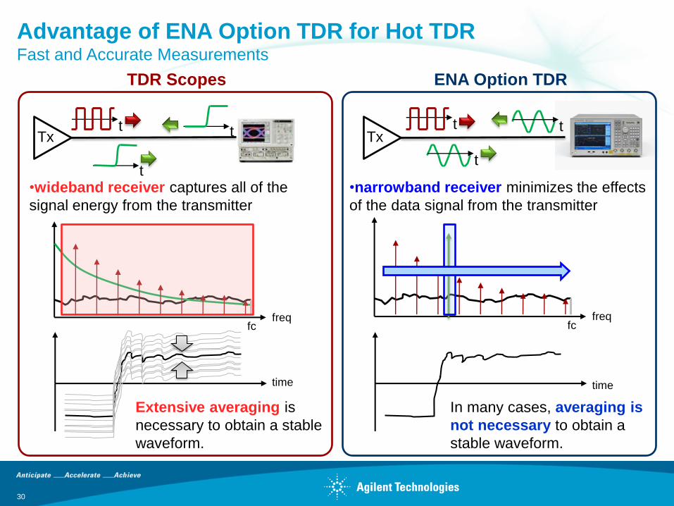
Advantage of ENA Option TDR for Hot TDR Fast and Accurate Measurements
30
t
freq fc
•wideband receiver captures all of the
signal energy from the transmitter
time
Extensive averaging is
necessary to obtain a stable
waveform.
fc
freq
•narrowband receiver minimizes the effects
of the data signal from the transmitter
time
In many cases, averaging is
not necessary to obtain a
stable waveform.
ENA Option TDR TDR Scopes
t t
t
t
t
Tx Tx
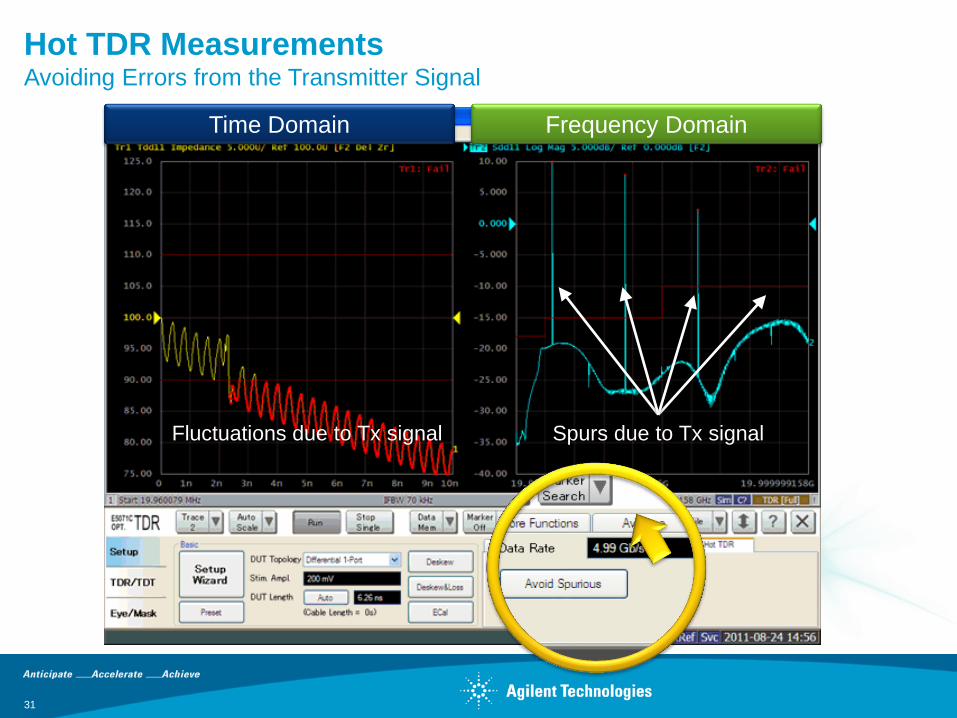
Hot TDR Measurements Avoiding Errors from the Transmitter Signal
31
Frequency Domain Time Domain
Spurs due to Tx signal Fluctuations due to Tx signal
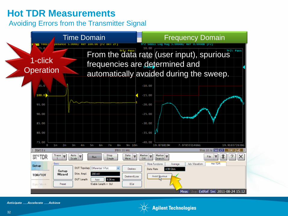
Hot TDR Measurements Avoiding Errors from the Transmitter Signal
32
Frequency Domain Time Domain
From the data rate (user input), spurious
frequencies are determined and
automatically avoided during the sweep.
1-click
Operation
Advantages of ENA Option TDR for Hot TDR Simple and Intuitive Operation
33
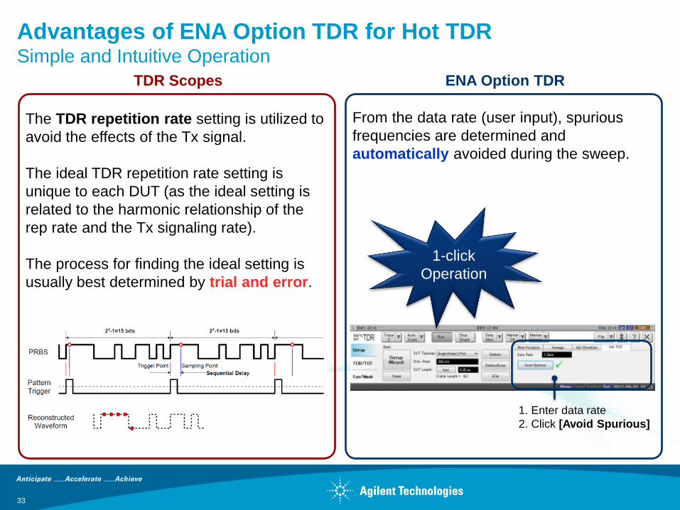
ENA Option TDR TDR Scopes
1. Enter data rate
2. Click [Avoid Spurious]
From the data rate (user input), spurious
frequencies are determined and
automatically avoided during the sweep.
The TDR repetition rate setting is utilized to
avoid the effects of the Tx signal.
The ideal TDR repetition rate setting is
unique to each DUT (as the ideal setting is
related to the harmonic relationship of the
rep rate and the Tx signaling rate).
The process for finding the ideal setting is
usually best determined by trial and error.
1-click
Operation
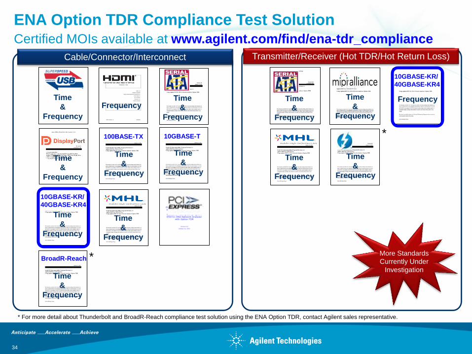
ENA Option TDR Compliance Test Solution Certified MOIs available at www.agilent.com/find/ena-tdr_compliance
34
Time
&
Frequency
Frequency Time
&
Frequency
Time
&
Frequency
Time
&
Frequency
Time
&
Frequency
Time
&
Frequency
Cable/Connector/Interconnect Transmitter/Receiver (Hot TDR/Hot Return Loss)
More Standards
Currently Under
Investigation
* For more detail about Thunderbolt and BroadR-Reach compliance test solution using the ENA Option TDR, contact Agilent sales representative.
*
Time
&
Frequency
Time
&
Frequency
100BASE-TX 10GBASE-T
Time
&
Frequency
Time
&
Frequency
10GBASE-KR/
40GBASE-KR4
Time
&
Frequency
BroadR-Reach
Time
&
Frequency
*
10GBASE-KR/
40GBASE-KR4
Frequency
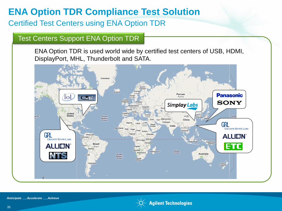
ENA Option TDR Compliance Test Solution Certified Test Centers using ENA Option TDR
35
Test Centers Support ENA Option TDR
ENA Option TDR is used world wide by certified test centers of USB, HDMI,
DisplayPort, MHL, Thunderbolt and SATA.
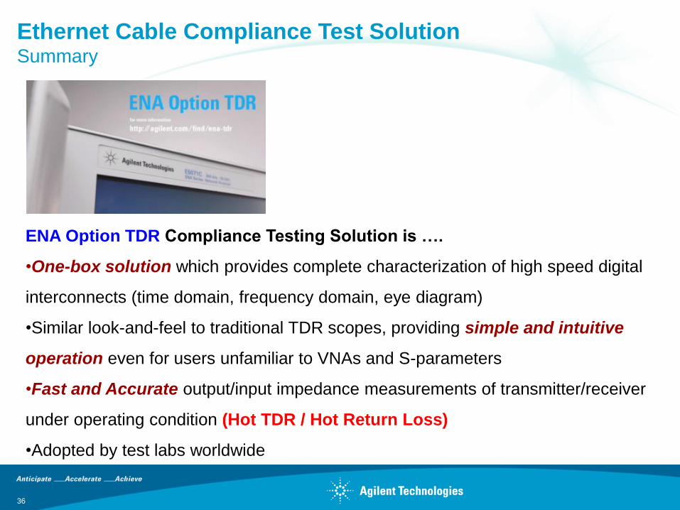
Ethernet Cable Compliance Test Solution Summary
ENA Option TDR Compliance Testing Solution is ….
•One-box solution which provides complete characterization of high speed digital
interconnects (time domain, frequency domain, eye diagram)
•Similar look-and-feel to traditional TDR scopes, providing simple and intuitive
operation even for users unfamiliar to VNAs and S-parameters
•Fast and Accurate output/input impedance measurements of transmitter/receiver
under operating condition (Hot TDR / Hot Return Loss)
•Adopted by test labs worldwide
36

Questions?
37
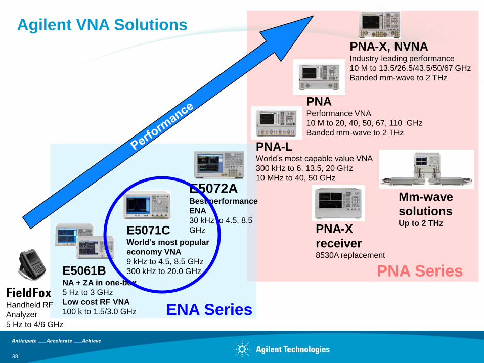
PNA-L World’s most capable value VNA
300 kHz to 6, 13.5, 20 GHz
10 MHz to 40, 50 GHz
E5071C World’s most popular
economy VNA
9 kHz to 4.5, 8.5 GHz
300 kHz to 20.0 GHz
FieldFox Handheld RF
Analyzer
5 Hz to 4/6 GHz
PNA-X, NVNA Industry-leading performance
10 M to 13.5/26.5/43.5/50/67 GHz
Banded mm-wave to 2 THz
PNA-X
receiver 8530A replacement
Mm-wave
solutions Up to 2 THz
PNA Performance VNA
10 M to 20, 40, 50, 67, 110 GHz
Banded mm-wave to 2 THz
E5072A Best performance
ENA
30 kHz to 4.5, 8.5
GHz
E5061B NA + ZA in one-box
5 Hz to 3 GHz
Low cost RF VNA
100 k to 1.5/3.0 GHz ENA Series
PNA Series
Agilent VNA Solutions
38
[Video]
Agilent ENA Option TDR
Changing the world of Time Domain Reflectometry (TDR) Measurements
What is ENA Option TDR?
39
•www.youtube.com/watch?v=hwQNlyyJ5hI&list=UUAJAjd97CfnCehC4jZAfkxQ&index=20&feature=plcp
•www.agilent.com/find/ena-tdr
Additional Resources
40
•ENA Option TDR Reference Material
www.agilent.com/find/ena-tdr
•Technical Overview (5990-5237EN)
•Application Notes
•Correlation between TDR oscilloscope and VNA generated time domain waveform (5990-5238EN)
•Comparison of Measurement Performance between Vector Network Analyzer and TDR
Oscilloscope (5990-5446EN)
•Effective Hot TDR Measurements of Active Devices Using ENA Option TDR (5990-9676EN)
•Measurement Uncertainty of VNA Based TDR/TDT Measurement (5990-8406EN)
•Accuracy Verification of Agilent’s ENA Option TDR Time Domain Measurement using a NIST
Traceable Standard (5990-5728EN)
•Method of Implementation (MOI) for High Speed Digital Standards
www.agilent.com/find/ena-tdr_compliance